

(
===========================
MITSUBISHI
1. * 1
2.
J:.
3.
it
4.
-f-
,
~
5.
T- ,~
6. }
If!
I
i.f
'IB
~
~
'IB
.ffAHft
§B
§B
§B
f
ft
~
-s-t· ·····Ar
-s-t·
-s-t
§B
-s-t
§B-s-t
§B
-s-t···
···
··Upper shaft Mechanis
···· ··Needl
·· ····Zig-Zag
······Needle vibrator crank operati
···Presser foot Mechanism ···
SEWING
Model··· ············ LZ
m bed · · · · · · · · · · · ·· · · · · · · · · · · · · · · · · · · · · · · · · · · · · · · · · · · · · · · · · · · · · · · · · · · · · · · · · · · · · · · · · · 1
e bar and take-up lever Mechani
motion Mechanism ··· · ···
::II
MACHINE
INDEX
.•
....
Jiifl
m··
=============================
PARTS
760
·····
·····
·····
··········
sm
···
· ·· · ·· · ··
ng
shaft Mechanism
···········
·················· ·· ······················ ···13
CATALOG
········ ···········
·· ·······
···
···
· ·············· ···
· ·· ·· ··· · · .. ··· · ·· ···· ·· · ·· · ·· ·· 9
······ .. ··
····
·····
···
······
···
······ ·
·····
···
5
· 7
11
7. *li§
8.
9.
10.
11.
;/JQ
~
'
*£i
)
83
1i !i
£(1
11
)~.tfi!H11
IB
~
Hm71
§B
-$t
fft
§B
-s-t
i~
£~)···
~······Acces
·
··
···
Stitch
···· ··Rotati
··· ···Oil lubrication Mechanism
··
·A
regulator Mechanism · · · · · · · · · · · · · · · · · · · · · · · · · · · · · · · · · · · · · · · · · · · · · · · · · · · · · ·15
ng
hook shaft Mechanism · · · · · · · · · · · · · · · · · · · · · · · · · · · · · · · · · · · · · · · · · · · · · · ·
ccessor
i
es
.
s
ories
box
· · ·· · · · · · · · · · · · · · · · · · · · · · · · · · · · · · · · ·· · · · · · · · · · · ·· · · · · · · · · · · ·· · · · · · · · · · · · · · ·
==================================================197603==
·······················································
···································································
MITSUBISHI ELECTRIC
CORPORATION
·17
··23
··2
7
29
==============::a.•
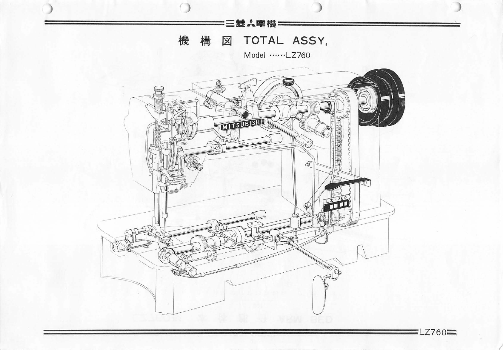
..
~fM===============
~
'M
~
TOTAL
Mode
l ....
ASSY,
.. L
Z760
==========================================================
L
Z760~
)
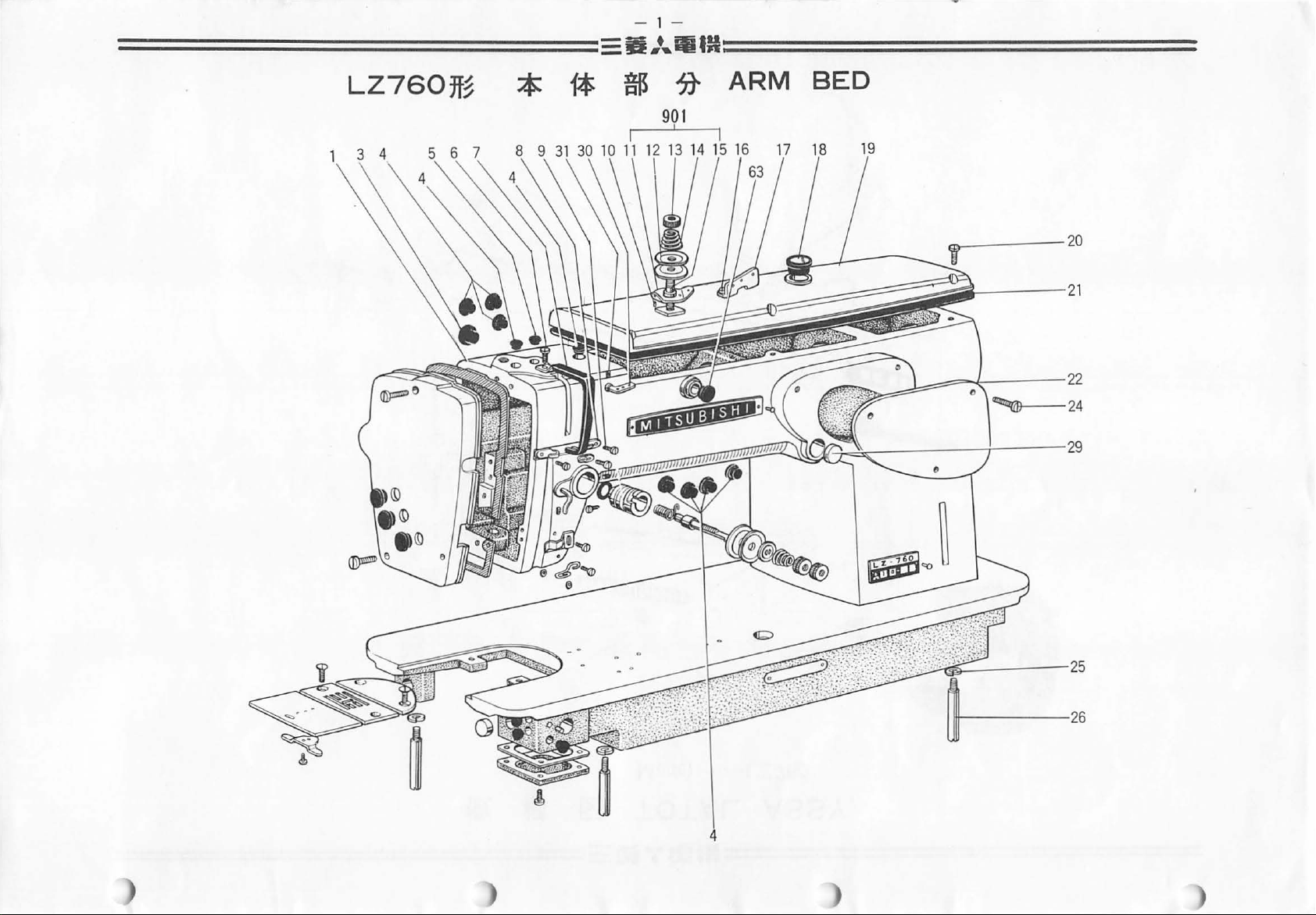
- 1 -
==============···
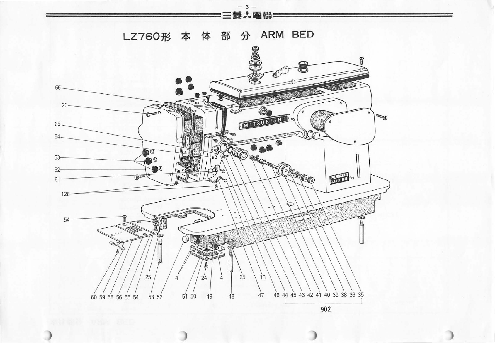
LZ760ff~
* 1* $
....
iliUI=============
90
?}-
1
I
ARM
BED
----2
0
111-----26
)
)
)
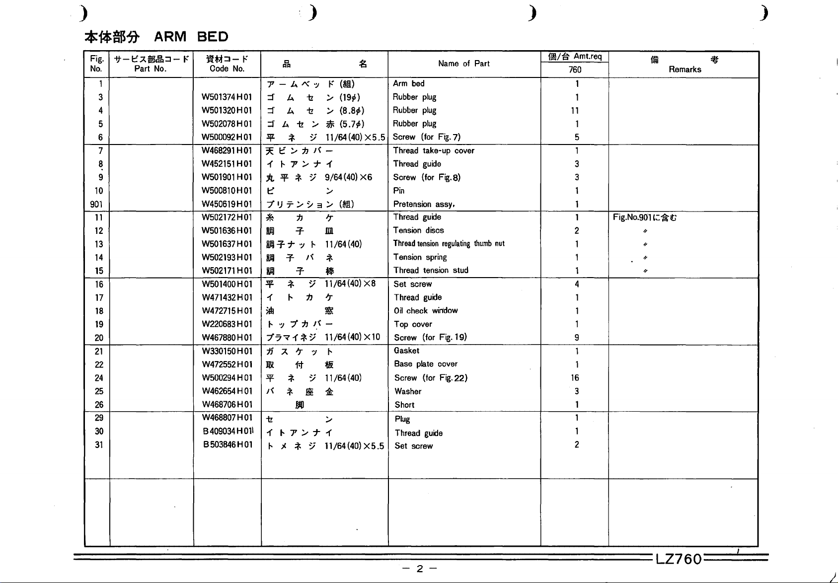
*1*$1t ARM
Fig.
-if-t:~ftfSdi.J::J-1"
No.
1
3
4
5
6
7
8
9
10
901
11
12
13
14
15
16
17
18
19
20
21
22
24
25
26
29
30
31
Part
No.
BED
-~;f::J-
Code
No.
W501374H01
W501320H01
W502078H01
W500092H01
W468291
W452151
W501901
W500810H01
W450619H01
W502172H01
W501636H01
W501637H01
W502193H01
W502171
W501400H01
W471432H01
W472715H01
W220683H01
W467880H01
W330150H01
W472552H01
W500294H01
W462654H01
W468706H01
W468807H01
8
B503846H01
409034
HOl
HOl
H01
H01
H
I"
1:1
1:11:1
7' - b.
:::f
b.
:::f
b.
:::f
b.
1z
3JZ
*
~
1::
/
J-.7'/7-1
1
:ll.lJZ*
t::
"1'
IJ
T:,..
tJ
*
DJj
lid
~
Uil
3lt
1
$
"1'7-v1-*~
:ml
3lt
I~
1z
011
1
=f
7
=r
*
"
" ':I
"1'
jj
~
*
*
J-.7'/7-1'
;1.
"
=r
=r
'r
it
JliO
*
/'\,'
•:J
1z
1z
:,..
~
tJ
I~
~
~
3:,..
·:~
I~
"
~
tJ
tJ
15
':J
~
I!!
~
~
I"
(,i)
:,..
(19,S)
/
(8.8,S)
~
(5.7,S)
11
/64 (
40)
X 5 . 5
-
9/64(40)
X6
:,..
(~.li)
'r
nn
11/64
(40)
*
•
11/64
(40)
X8
'r
~
-
11/64(40) X10
"
tli
11/64
(40)
'i:
:,..
11/64(40)
X5.5
Arm
bed
Rubber
plug
Rubber
plug
Rubber
plug
Screw
(for
Thread
take-up
Thread
guide
Screw
(for
Pin
Pretension
Thread
guide
Tension
Thread
Tension
Thread
Set
Thread
Oil
Top
Screw
Gasket
Base
Screw
Washer
Short
Plug
Thread
Set
discs
tension
spring
tension
screw
guide
check
cover
(for
plate
(for
guide
screw
Name
Fig.
7)
cover
Fig.
8)
assy.
regulating
stud
win'dow
Fig.
19)
cover
Fig.
22)
of
Part
thumb
nut
1!1/~
Amt.req
760
1
1
11
1
5
1
3
3
1
1
1
2
1
1
1
4
1
1
1
9
1
1
16
3
1
1
1
2
Fig.No.901
~
~
~
~
fiiD
Remarks
':~t;
='t
-2-
I
LZ760
- 3 -
===============--
=
LZ760ff~
*
1*
t
=D•,EI!"
~
aEifU================
;t
ARM
BED
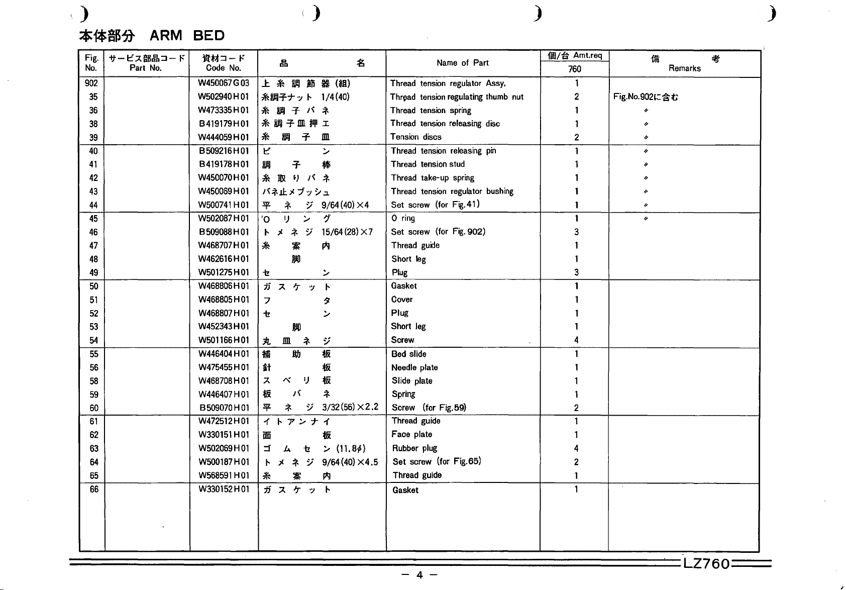
902
)
)
Fig.
No.
902
35
36
38
39
40
41
42
43
44
45
46
47
48
49
50
51
52
53
54
55
56
58
59
60
61
62
63
64
65
66
oft-
t:
.A$~
Part
No.
:J
-
I"
Jf.M:J- I"
Code
No.
W450067G03
W502940H01
W473335H01
B419179H01
W444059H01
8509216H01
B419178H01
W450070H01
W450069H01
W500741
W502087H01
B509088H01
W468707H01
W462616H01
W501275H01
W468806H01
W468805H01
W468807H01
W452343H01
W501166H01
W446404H01
W475455H01
W468708H01
W446407H01
B509070H01
W472512H01
W330151
W502069H01
W500187H01
W568591
W330152H01
H01
H01
HOl
Q
gg
J:.
*
~
iii B
* D.Ffr
*
u.J
T-
*~-TIIJ1fil3I
B.!
*
t:"
i.IJ
J&
*
I '\ *
!1:.
.)(
3JL
'*
l)
·o
.)(
t-
*
*
-tz
jj
.A
7
-tz
IIJl
:J:r.
M
it
/'\,
.A
·:~
t-
'"
.:r
.:r
~)
'"
7 ':I
~
/
~
~
DID
'r
':I
JJIO
'*
Db
l)
1/4(40)
-*
IIJl
/
•
'*
~
.:z.
9/64
~
15/64
I*J
/
t-
~
/
~
ti
ti
ti
(*11)
(40)
(28)
:g
X4
X 7
ti
3Jl.
1
ifii
=r
t-
*
jj
'"
'*
t-7/7"1
k.
.)(
'*
~
.A
'r
~
-tz
:;
':I
'*
3/32
(56)
ti
/
(11.
9/64(40)
I*J
t-
X 2
.2
8~)
X4.5
Name
of Part
Thread tension regulator Assy,
Thr~ad
tension regulating thumb nut
Thread tension spring
Thread tension releasing disc
Tension discs
Thread tension releasing
Thread tension stud
Thread take-up spring
Thread tension regulator bushing
Set screw
0 ring
Set screw
Thread
Short
Plug
Gasket
Cover
Plug
Short
Screw
Bed slide
Needle plate
Slide plate
Spring
Screw (for Fig.-59)
Thread guide
Face plate
Rubber plug
Set
Thread guide
Gasket
(for Fig.4 1 )
Fig.
(for
guide
leg
leg
screw (for Fig. 65)
pin
902)
11/a Amt.req
760
1
2 Fig.
1
1
2
1
1
1
1
1
1
3
1
1
3
1
1
1
1
4
1
1
1
1
2
1
1
4
2
1
1
No.
1a
902';:
~
~
~
~
~
~
~
~
~
Remarks
~
t;
:iff
'
========================================================~=LZ760=··===
-4-
- 5 -
==============•·•,ititH============
LZ760ff~
J:.
fib
78
79
rus
80
81
;t
83
UPPER
SHAFT
92
93
MECHANISM
94 95
96 97
98
10
10
11
111
=
8
9
0
~---
(5
1 ) L Z
B
$t.J"'.Wf.J:
---
760ff~
C:
L Z
750ff~
~)
* 9 o
-
-
95
lj:
A$
C:
)
)
)
J:.$111$~
Fig.
-tt-t:~$~:::1-l"
No.
70
71
72
73
74
75
76
UPPER
Part
No.
n
78
79
80
81
83
84
86
88
91
92
93
94
95
96
97
98
904
105
106
107
108
109
110
111
112
SHAFT
JUt::~-
Code
8503851
W468734H01
B504016H01
W502474H01
W500003H01
W501905H01
W462698H01
W500006H01
W474380H01
W502945H01
W468731
W464441
B509087H01
W470214H01
W333589H01
W472551
W461784H01
W468737H01
B503852H01
W468789H01
B508963H01
W501212H01
W468832H01
W330158H01
W445869H01
W330157H01
W500509H01
W500246H01
W500233H01
W502088H01
W461758H01
W468788H01
I"
No.
H01
H01
H01
H01
MECHANISM
g
AJ:I
~
.:r
~
7
~
*
*
IJ
IJ
':I
-1
;...
:;
::f
*
:;
:;
-
:;
:;
-"'Jll
?
:;
:;
::f
;...
9/32
/]
1/4{40)
5/16
/
;...
)I,
:;
Jj,
15/64
IJ
Jj,
15/64
-
*ill
k
Jj,
)I,
11/64(40) X10
?
15/64(28)
15/64
1--.
1--
-
'T
-
15/64(28) X12
11/32
;...
11/32
?
~--·
-~3¥*:/
/]
7
j.
1--
*
jz,.DD.*:l
•t
•
I~
i:!
:t
-(
)j, ~ -
j.
1--
j.
3Jl
*
:t
j.
j.
t-
*
11
J:.
,.
?
:t
-(
Jll ~ -
j.
j.
1--
'"
l¥
*
.$'Cjz,Sf!*:l
~·-(
~
;...
~-(
~
/-1-"'Jll
7"
:;
/]
7"
l¥
*
3Jl
*
H
':I
~il*:l
IJ
0
~-(
~
/?-"'Jll
:g
{28) X 14
X6
{28)
X7
(28)
X8
(28)
X6
XlO
(28)
(~Jl)
(28) X 17
(28)
P4
.5
Set screw
Crank
Set
screw
Screw
Paking
.Plug
Oil
seal
Set
screw
Upper
shaft
Screw
Balance
Upper
shaft
Set
screw
Upper
shaft collar
Upper
shaft
Wonn
gear
Oil
seal
Upper
shaft
Set
screw
Spring
flange
Screw
Screw
Belt
pully
Connection
Balance
Ball
bearing
Balance
screw
Set
Set
screw
Packing
Screw
0
ring
Belt
pully
Name
{for
Fig.
(for Fig.78)
bushing
weight
bushing
(for Fig.81)
bushing
(for
Fig.
(Upper}
belt
wheel
Assy
wheel
(for Fig.l 06)
(Under)
of
Part
71
(left)
(middle)
(right)
92)
111~
Amt.req
760
)
14
10
1
1
2
2
3
1
3
1
5
1
1
1
1
1
1
1
3
3
3
1
1
1
1
1
1
4
1
1
1
2
1
Fig.No.904
,
m
t~
~
Remarks
t;
:11
=============================================================LZ760===
-
6-

-7-
=============EIIJ,ififll=============
ti
• ·
IS
~
LZ760ff~
134
133
131
130
129
905-{121
122
NEEDLE
BAR AND
145
146
A
115
TAKE-UP
905
8 C D
116
LEVER
E F G
MECHANISM
77
)
) )

,)
()
) )
tf-f*$~
Fig.
if-l::!'~$~:::J-I'"
No.
905
A
115
B
NEEDLE
Part
No.
c
D
116
E
F
G
117
118
119
120
121
122
123
124
126
127
128
129
130
131
132
133
134
140
141
142
143
144
145
146
BAR AND
-~~:::J-1'"
Code
No.
W330155H01
W502076H01
W468722H01
W468721
W450060H01
W450062H01
W470229H01
W450058H01
W502077H01
W468720H01
W468724H01
W468719H01
W500231
W468723H01
W472531
W502074H01
W468259H01
W333580H01
S561121
W468718H01
W468725H01
W474386H01
W474387H01
W468839H01
W502071
W468710H01
W502350H01
W468709H01
W330154H01
W468711
W468713H01
W468710H01
H01
H01
HOl
H01
H01
H01
QQ
~
l::!'
~.lJL:?-.
ll
~l::!'/?7/?
=-I'"
=-
$&
7Cl::!'/?7/?0·:;
7C
I\
7/-J--1
tJ
~
l::
it
J:L
3JL
i:L.lJL:?-.
*
it~~;l.
tifilt.J7/t::/
r\
~~
~
-if
-if
it
-t!
~/·')~:/?
1::
tJ
if
-;·
-
7
:;
TAKE-UP
1:1
/
~
tl
~
(~I!)
:;
9/64
(40)
fl
~
)t,
0-7
j'"Jt,0-7-~71)
1-t
•
I''
l::!'
/
;1.
"
~-1
:::] "':{
?
J!
•
*
*
J!
'"
':I
:;
*
t
~
~
:;
9/64
:;
~
·:;''J 19:13
~
!!
*
!:*]
t&
jj
jj
tf
-
if
~
/"(
t:•
(40)
1/8(44)
!:*]
SKF70
:;
*
*
/
/
I
~
/
?
X4.5
::g
/IJ
X9
LEVER
Thread
connecting
left
Needle
Thread
Needle
Needle
Set
Thread
Thread
Thread
Needle
Sqt1are
Screw
Oil
Needle
Screw
.5
Needle
Thread
Needle
Thread
Spring
Screw
Base
Washer
Washer
Needle
Plug
Pin
Pin
Cover
Support
Bushing
Pin
Shaft
thread
pin
wick
plate
·
Name
take-up
crank
screw
bar
connecting
take-up
roller
roller
take-up
take-up
take-up
bar
connecting
block
bar
connecting
(for
Fig.
clamp
guide
take-up
washer
bar
MECHANISM
of
Part
lever
and
crank
crank
eyelet
link
stud
needle
rod
rod
guide
rod
(for Fig.115)
crank
beanng
lever
lever
lever
121)
screw
lever
bar
11!1/~
Amt.req
760
1
1
1
1
18
2
1
1
1
1
1
1
1
1
1
1
1
1
1
1
3
1
1
1
1
1
1
1
1
1
1
2
1
1
1rm
Fig.No.905':~t;
//
//
//
//
//
//
//
//
Fig.No.905':~t;
//
~
===============================================================LZ76o----
-
8-
-9-
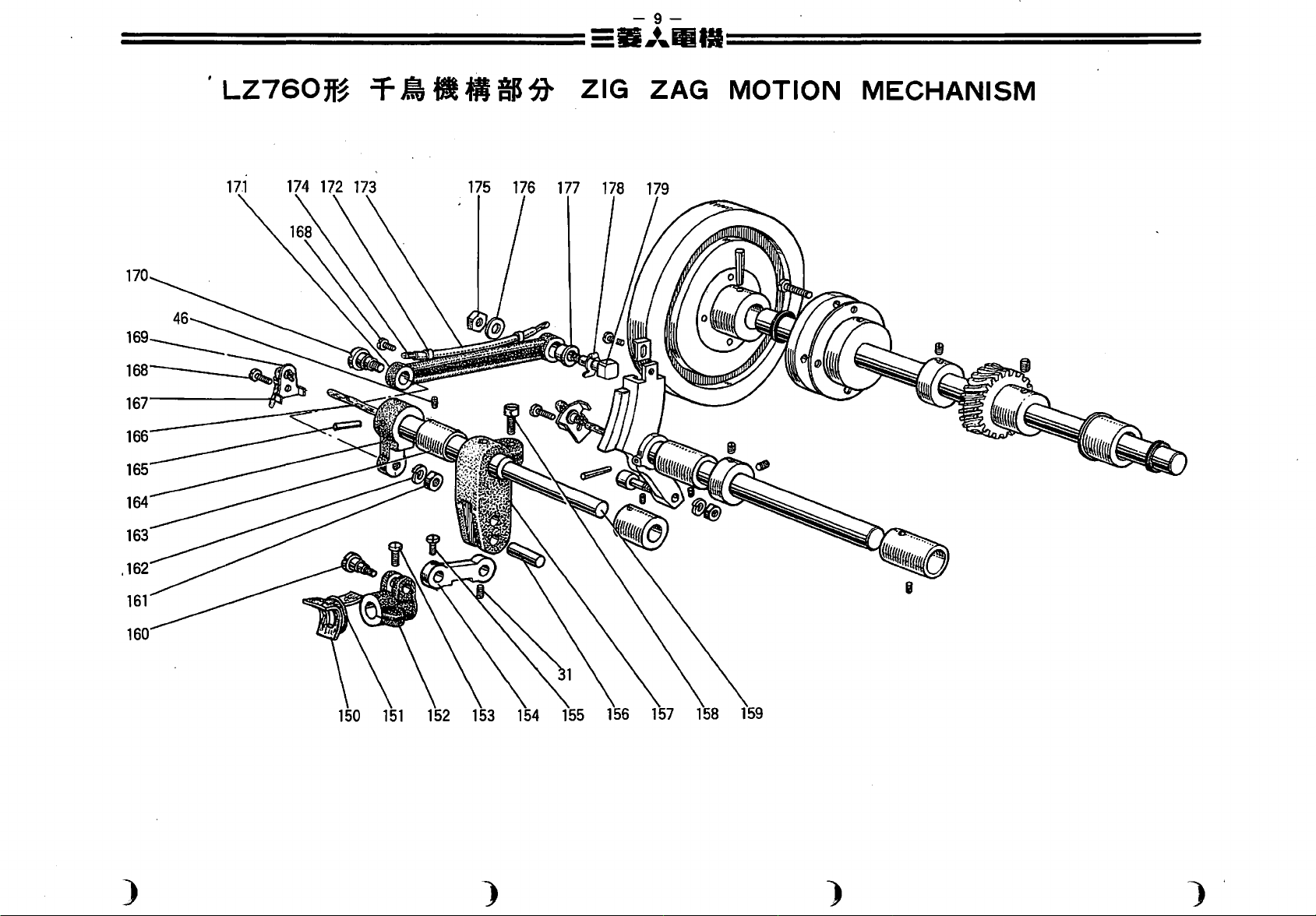
=============E:il.•
'
LZ760~~
170
166
165
T
••
a
IS~
ZIG
...
llitl=============
ZAG
MOTION
MECHANISM
164
163
161
)
) )
)'
 Loading...