

Page 1
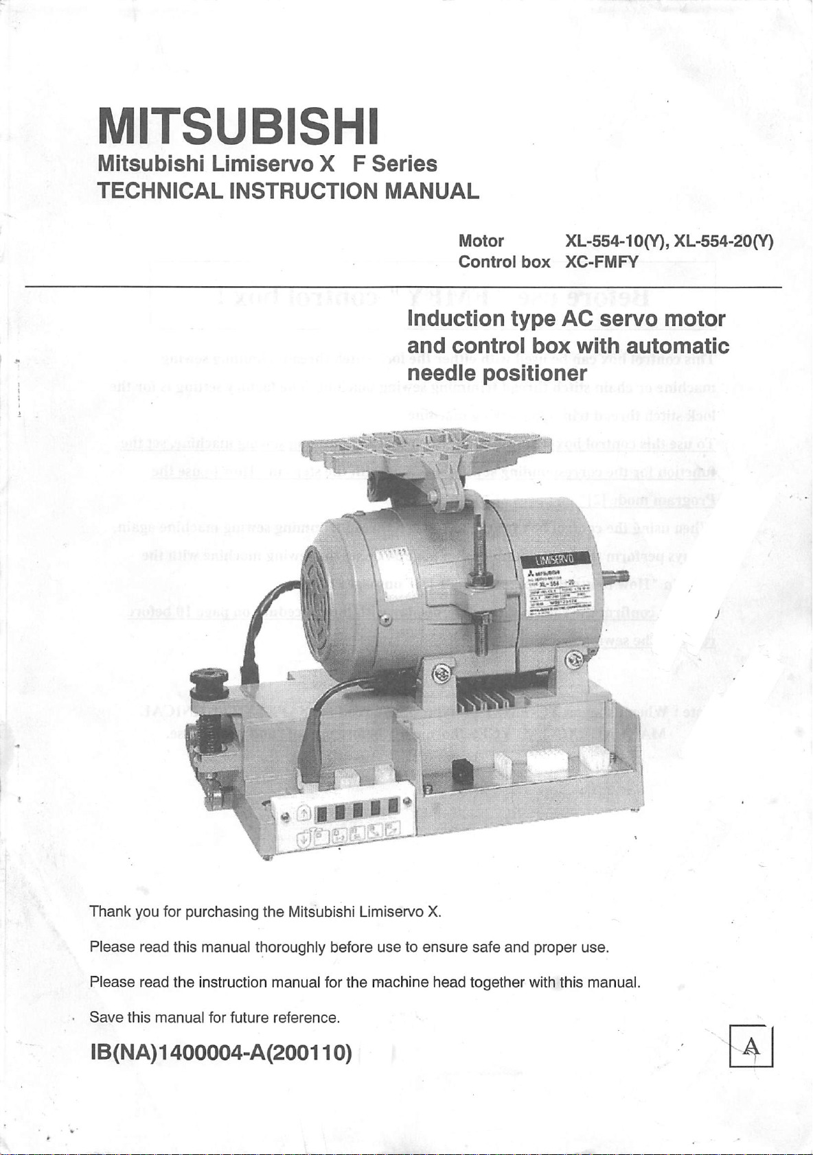
MITSUBISHI
Mitsubishi
TECHNICAL
Limiservo
iNSTRUCTiON
X F
Series
MANUAL
induction
and
needle
Motor
Control
control
positioner
box
type
box
XL-554-10{Y),XL-554-20(Y)
XC-FMFY
AC
servo
with
motor
automatic
Thank
Please
Please
Save
you for
read
read
this
purchasing
this manual thoroughly before
the
instruction manual for
manual
for
future
the
Mitsubishi Limiservo X.
reference.
usetoensure
the
machine
safe
and
proper
head
together withthis manual.
iB(NA)1400004-A(200110)
use.
Page 2

This
Before
control
box
canbeused
use
"
FMFY"
with
either
the
control
lock
stitch
thread
box
trimming
!
sewing
machineorchain
lock
stitch
To
use
function
Program
When
always
steps
(Always
running
Note :
thread
this
for
mode
using
perform
in "
Howtouse
confirm
the
When
control
the
the
sewing
using on
MANUAL
stitch
thread
trimming
box
with
corresponding
[21"
on
pages
control
the
box
reset
the
the
rotation
machine.)
XC-FMFYCE
<XC-
FMFYCE>
trimming
sewing
the
chain
sewing
21to22.
for
the
operations
program
direction
sewing
machine.
stitch
machine
lock
stitch
on
page34or
mode
[1]"
disnlav
type, please
thoroughly
thread
thread
on
with
machine.
trimming
with
the
trimming
set
the
pages
the
read
before
The
steos
sewing
16.
procedure
the
SAFETY
use
safe
factory
sewing
in
"How
sewing
machine
and
settingisfor
machine,
to
use
machine
with
on
page
10
TECHNICAL
proper
use.
set
the
again,
the
before
the
the
Page 3
n~l
Contents
Safety
[Y\
PointsofCaution
Q
NamesofEach
[~5l
Accessories
n~l
Contents
Instruction
Parts
3
4
5
5
Q
[s]
[~^
Installation
1.
Installationofthe
2.
Installationofthe
3. Installationofthe pulley 6
4. Mountingofthe belt 6
5. Installationofthe protective cover 7
6. Installationofthe position detector 8
7. Connection
Wire
and
Grounding
1. Insertion of the power connector 9
2. Connection
3. Current Capacity 9
4. Whenusingthe3-phase200~240Vclass LimiservoX with single phase 200~240V class 9
motor
control
of
the Mitsubishi sewing machine and control box 8
of
3-phase power 9
box
Confirmation
1. Before turning switches on 10
2. Turn on the power 10
Adjustments
1. Adjustment of stopping position 11
2. Adjustment of pedal toe down pressure, and healing pressure 11
3. Adjustment of operation speed 11
6
6
6
9
10
11
10 Howto changevoltageof panel connector and solenoidreturn speed 12
1. To changesolenoid voltage
2. Howto change the outputvoltage DC5V/12V and 0V/DC5V 13
3. How to setthe switch for increasingthe solenoid return speed 13
[II]
Operationofoperation
1. Display during
2.
Selectionofeach
3. Howto use programmode[1]
(Simple
Display
4.
(1)
(2)
(3)
(4)
12
How
1.
How
2. Simplesetting tableforchain
setting
and
functions
Tacking
setting
No.oftacking
Preset
stitching
Pattern
touse
Simple
touse
No.
program
panel
keys
normal
table
selection
modeand
mode* 14
for
Mitsubishi
of eachkeyinthe
mode
stitches
setting
setting
mode
function
thread
mode
of eachkey 14
trimming
tacking
sewing
machine
modeand
and
pattern
motor
pulley
outside
diameter.)
mode 18
mode
settingofProgram
mode
[2] 20
stitch
mode
sewing
[2]
(forchainstitchtrimming
machine
machine)
17
19
21
14
20
Page 4
1.Contents
13 How to use SimplesettingofProgram
1. How to useprogram mode [3] 22
2. Simple setting table for lock stitch sewing machine 23
141
Howtouse
1. To change the maximum speed 24
2. To set the standing work type 24
3. To operate Half-stitch operation with a backstitching switch 25
4. To output a puller output to spare output
5. To set the number of stitches to the needle UP position stop
after detecting thefabric end with an optical sensor, etc. 26
6. To continue presser foot lifting after trimming, and to bring down
the presser foot after the time set on timer has passed 27
7. To set needleposition higher than usual after thread trimming 27
8. To displaythe rotationalspeedof thesewing machinebe in running 28
9. To run withoutdetector
10. To adjust tacking accurately 29
11.
Down
12. To checkthe errorcode history and input/outputsignal 32
13. To returnall settings to the factorysetting 34
14. Toset the
1^
To
save
1.
How
program
counter
ON/OFF
the
setting
tousethe
mode
(exampleofmost
(When
for
bobbin
remain
operation of the thread
data
program
mode
mode [3] (for lock stitch
frequently
02
detectoris
thread
broken)
count
trimming
(10,000
using)
stitches is
protective signal 35
trimming
count
over)
machine) 22
[I ] (SAVEmode) 36
24
25
28
31
36
16 To adjust the neutral, toe down, heelingpositiondata of the pedal 37
How
1.
17 Function List 38
181
Howtouse
1. Connectorlayout
2. To useasa standing worktypesewing
191
Error
20 Specifications
21 Table ofdigital displayand Dimensions 44
tousethe
Display
the
program
option
mode
connector
[ Q ]
machine
40
41
42
-2-
Page 5
Safety Instructions
1.Toensure
-
Always
1.1 Before starting
- Read all instruction manual thoroughly before starting use of this drive unit, and follow the technical manuals.
safe
observe
use
the
following
itemstoensure
safeuseofthe
industrial
sewing
machine
drive
unit
(motor
and
control
box).
Also readthe instructionmanualsfor the installedsewingmachine.
1.2 Application and purpose
-This driveunitis designedtodrivea sewingmachineand mustnot be usedforotherapplications or purposes.
Do not usethis drive unit until it can be confirmed that safety measuresfor the installedsewing machine have been taken.
1.3
Work
environment
- Use this drive unit in dry and well-keptclean locations, e.g. in the clothing industry, and which process dry sewing material.
- Avoid using this control unit in the following typesof environments.
(1) Powervoltage - Place where voltage fluctuation
- Place where frequency fluctuation
(2) Electromagnetic noise - Place where strong electric or magnetic fields are generated such as near a
(3)
Temperature
(4) Atmosphere - Atmosphere with dust or corrosive gases.
(5) Altitude - Place where at altitudes exceeds 1,000m above mean sea level.
(6)
Storage
(7) Vibration - If excessive vibration occurs when the control box is installed on thesewing machine, install it separately.
2.
Installation
2.1
Motor
- Correctly install according to the attached technical manuals.
2.2
Accessories
- Always disconnect this control unit from the main power supply when installing any accessories listed in thetechnical manual.
(Turn the main switch OFF, and remove the plug from theoutlet (power supply line).)
2.3
Cable
and
and
control
humidity-Place
box
- Place where the specified power capacity cannot besecured.
large-output high
where
- Place subject to direct sunlight or outdoors.
-
Nearaheat
- Place where relative humidity is 30% or less and 95% or more, or where dew condensation occurs.
- Atmosphere with combustible gases or explosive atmosphere.
-
Place
where
fi-equency
atmospheric
source
suchasa
storage
temperature
exceeds±
oscillator or high frequency welding machine.
temperatureis40T^orhigher
heater.
isSSt) or
10% of the rated voltage.
exceeds±l%
of 50/60Hz.
higher
and or
and
-2^orlower.
lower.
(1) Arrange the connectioncable so that excessive force isnot applied duringuse, and do not excessivelybend the cable.
(2) Cablesnearmovingparts(e.g.,pulleyor V-belt)mustbe wiredat a
(3) Confirm that the power voltage of the power cable for supplying tothe control box meets the specificationson the motor
and control box rating nameplates before connecting it to the power line.
minimum
distanceof 25mm.
Connectit to the designatedplacesto supply the power. Performthis step with the powerON/OFFswitch turnedOFF.
2.4 Grounding
(1) Correctly connect thecontrol box groundingto the power supply grounding.
2.5 Accompanying appliances and accessories
(1) Electric accompanying appliances and accessories must only be connected to safety low voltage.
2.6
Removal
(1) Turn the main switch OFF and removethe plug from the outlet (power supply line) before removing the motor or controlbox.
(2) Do not pullon the cord when removing the plug. Always hold the plug itself.
(3) There is a high voltage applied insidethe control box, so always wait at least 10 minutes after runningthe power switch
OFF and remove the plug from theoutlet(power supply line) beforeopeningthecontrol box panel.
3. Maintenance, inspection
and
repairs
- Follow the technical manualsfor maintenanceand inspectionof this control unit.
- Repairsand maintenancemustbe done and approved by specially trained personnel.
- Do not run this control with the ventilation openings of the motor's dust-proof filter blockedor clogged with dust, loosecloth, etc.
- Always turn the main switch OFF and remove the plug from the outlet (power supply
before replacing the sewing machine needle or bobbin, etc.
line)
- Always useoriginal replacementpartsfor repairsor maintenance.
4.
Other
safety
measures
- Keep fingers away from all moving parts(especially near sewing machineneedle, V-belt,etc.).
- Do not drop this control unitor insert any object intoany opening.
- Do not operate without required protective devices.
- During power-onor forsome time afterpower-off,do nottouch thecontrol box.
The temperature of the control box surface may be high and you may get burnt.
- If any damage is observed on this control unit, if the drive does not run properly or if operator is uncertain about operation,
do not operatethe drive unit.Operatethe drive only afteradjustments,repairsand approvals have been made by qualified personnel.
- The user must avoid makingmodificationsor changes basedon user's judgment.
Observe all safety guidelines if modificationsor changes must be made.
- When system have to be stop incase of emergency, removethe powersupply plug from the power supply line.
5.
Hazard
display,
warning
display
(1) Risksthat maycause personal injury or risk to the machine
are marked with this symbol in the instruction manual.
(2) This symbol indicates electrical risks andwarnings.
(3) This symbol indicates thermal risks and warnings.
Save these technical manuals for future reference.
..
3
Page 6
Q
Please
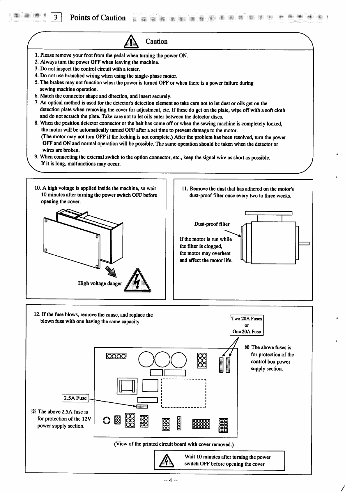
Alwaysturn the power OFFwhen leavingthe machine.
Do not inspect the control circuit with a tester.
Donot use
The
brakes
sewing machine operation.
Matchthe connectorshapeand direction,and insert securely.
An
optical
detection
and do not scratchthe plate.Take carenot to letoils enter between the detector discs.
8.
When
the
motor
(The
OFFandONand
wires
When
If it is long, malfunctions may occur.
PointsofCaution
remove
yourfootfromthe
branched
may
methodisused
plate
the
position
willbe
motor
may
are
broken.
connecting
wiring
not
function
when
removing
detector
automatically
not
turn
normal
the
external
Caution
pedal
when
turning
whenusingthe single-phase
when
the
poweristurned
forthe
the
connector
OFF
ifthe
operation
switch
detector's
cover
turned
detection
for
adjustment,
orthebelthas
OFFaftera settimeto
locking
isnot
willbe
possible.
tothe
option
thepowerON.
motor.
OFForwhen
elementsotake
etc.If
come
offor
complete.)
Thesame
connector,
these
when
prevent
After
operation
etc.,
keep
there
isa
carenotto letdustor oilsgetonthe
dogetonthe
the
sewing
damage
the
problem
shouldbetaken
the
signal
power
failure
during
plate,
wipe
off
machineiscompletely
tothe
motor.
has
been
resolved,
when
wireasshortas
with
turn
the
detector
possible.
asoft
locked,
the
cloth
power
or
10.A high voltage is applied insidethe machine,so wait
10 minutesafterturning the powerswitch OFF before
opening the cover.
High voltagedanger
12.If thefuse
blownfusewithone
blows,
remove
thecause,andreplace the
having
thesamecapacity.
IQQ^
ooo
11.
Remove
dust-proof filter onceevery twoto threeweeks.
If
the
the filter is clogged,
the motor may overheat
and
affect
the
dust
Dust-prooffilter
motorisrun
the
while
motor
that
life.
Two
One
has
20A
20A
adheredonthe
Fuses
or
Fuse
^
The
above fuses is
for protectionofthe
control box power
supply section.
motor's
2.5A
Fuse
^
The
above
2.5A
fuse is
for protectionofthe 12V
powersupply section.
(View
of the
printed
circuit
board
with
cover
removed.)
Wait10
switch OFF beforeopening the cover
-4..
minutes
afterturningthe power
/
Page 7
Q
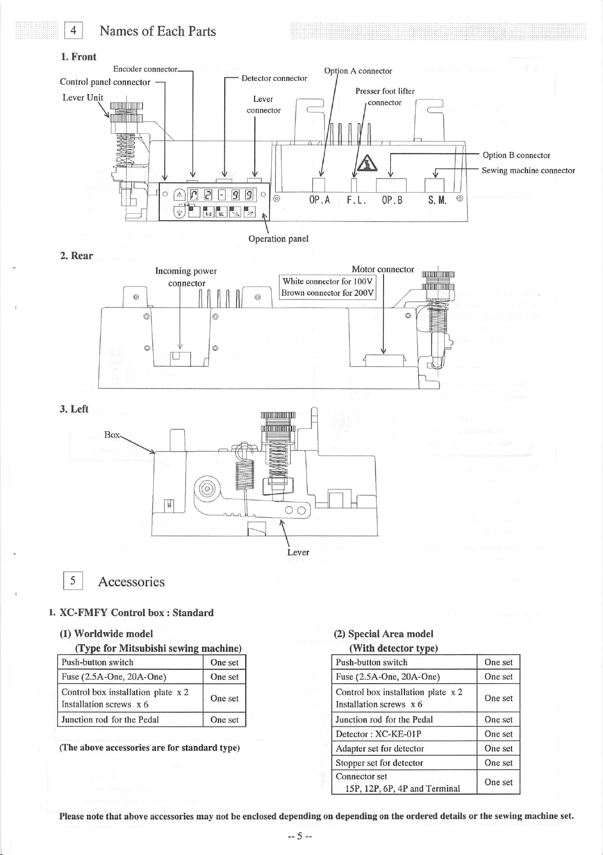
1.
NamesofEach
Front
Encoder
Control panel connector
Lever
Unh
connector-
Parts
Detector
connector
Option A connector
Presser
foot
lifter
Option B connector
Sewing machine connector
'®
OP.A
F.L.
OP.B
S.M. ®
Operation panel
2.
Rear
Motor
Incoming power
White
connector
3.
Left
Brown
connector
connector
for
for
connector
lOOV
200V
Accessories
1.
XC-FMFY
(1)
Worldwide
(Type for Mitsubishi sewing machine)
Push-button
Fuse (2.5A-One, 20A-One) One set
Control box installation plate
T .11.• One set
InstallatJon
Junction
(The
above
Control
switch
screws
rod
for
accessories
box:Standard
model
x 6
the
Pedal
are
x2
for
standard
One
^
One
One
set
set
set
type)
(2) Special
Area
model
(With detector type)
Push-button
Fuse (2.5A-One, 20A-One)
Control box installation plate x 2
Installation
Junction
Detector:
Adapter set for detector
switch
screws
rod
for
the
XC-KE-OIP
x 6
Pedal
Stopper set for detector
Connector
set
15P, 12P, 6P, 4P and
Please note
that
above accessories may not be enclosed
depending
on depending on the
ordered
One
set
One
set
One
set
One
set
One
set
One
set
One
set
One
Terminal
set
detailsorthe sewing machine set.
Page 8
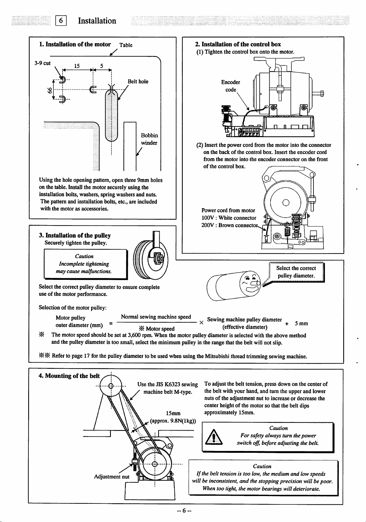
0
1.
Installationofthe
Installation
motor
Table
^
3-9
cut
\4
15 , 5
Belt
hole
Bobbin
winder
/
Using the hole opening pattern,open three 9nini holes
on the table.Install the motorsecurely usingthe
installation bolts,washers,springwashersand nuts.
The pattern and installation bolts, etc., are included
with
the
motorasaccessories.
3. Installationofthe pulley
Securely tighten the pulley.
2.
Installation
of
the
control
box
(1)Tighten the controlbox onto the motor.
Encoder
code
m
(2) Insert the power cord from the motor into the connector
on
the
from
of
Power
lOOV:
200V:
backofthe
the
the
control
cord
White
Brown
motor
box.
from
connector
connector.
into
motor
control
the
box.
encoder
Insert
the
encoder
connectoronthe
cord
front
Caution
Incomplete tightening
may cause malfunctions.
Selectthecorrectpulleydiameterto ensurecomplete
useofthe motor performance.
Selection of the motor pulley:
Normal sewing machine speed
-
besetat
3,600
Motor
rpm.
When
^
Motor pulley
outer
diameter
The
motor
speed
(mm)
should
andthepulleydiameter is toosmall,selectthe
Refer
topage17forthe
pulley
diameter
to be
4. Mounting of the belt
Use the JIS K6323 sewing
machine belt M-type.
(approx. 9.8N(lkg))
speed
the
minimum
used
when
15mm
motor
pulley
using
Select
the
pulley diameter.
Sewing machine pulley diameter
pulley
diameterisselected
(effective
diameter)
with
the
above
+ 5
method
inthe rangethatthebeltwillnotslip.
the
Mitsubishi
thread
trimming
sewing
machine.
To adjust thebelt tension,press down on the center of
the belt withyour hand,and turn the upper and lower
nuts of the adjustment nutto increase or decrease the
center heightof the motor so that the belt dips
approximately 15mm.
Caution
For
safety always turn the power
off,
switch
before adjusting thebelt.
correct
mm
Caution
Adjustment nut
If the belt tensionis too
willbeinconsistent, and thestoppingprecisionwillbepoor.
When
too tight, the motorbearings willdeteriorate.
~6
low,
the
medium
and lowspeeds
Page 9
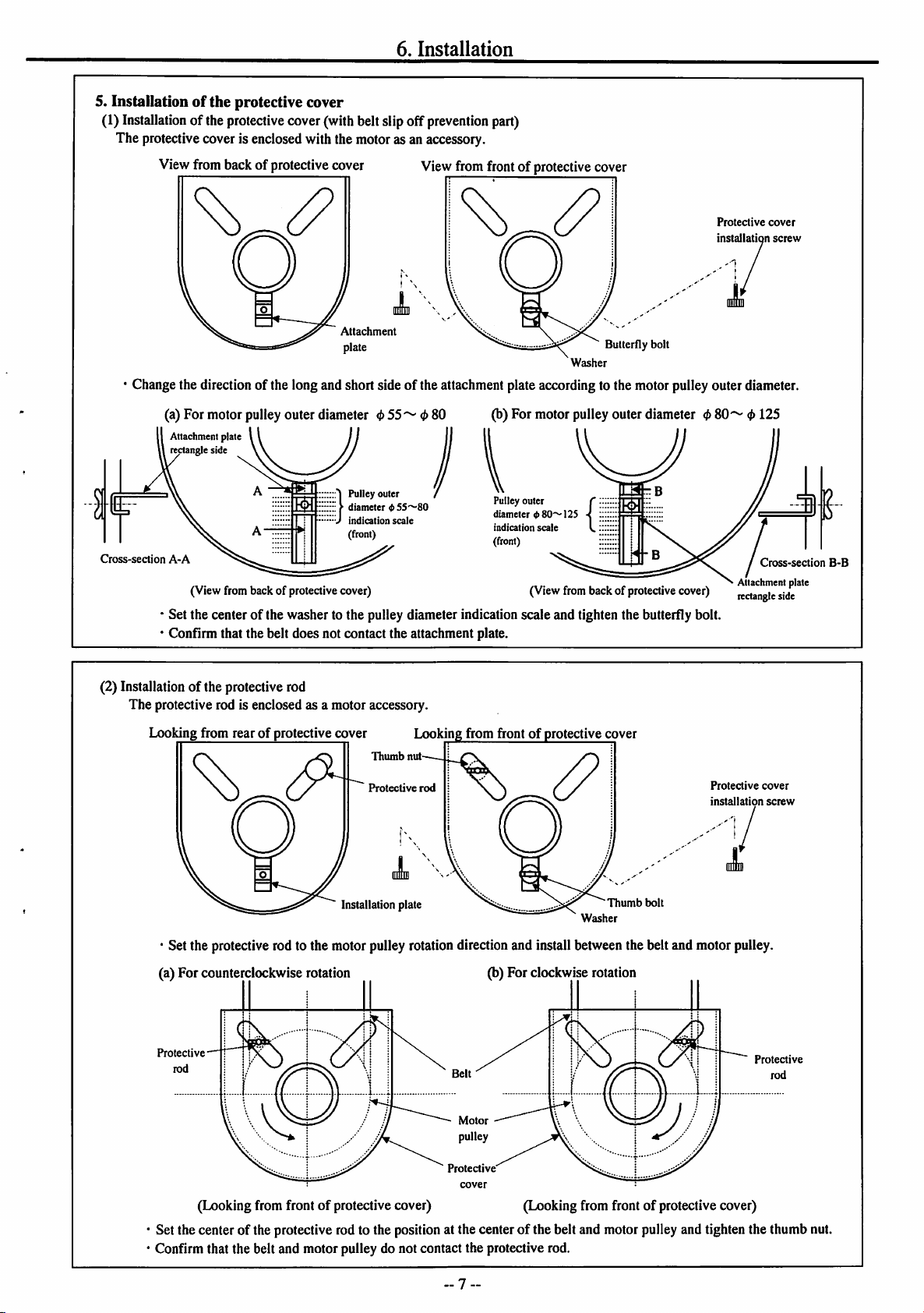
6.
Installation
5. Installationof the protective cover
(1) Installation ofthe protective cover(withbeltslipoff
The protective cover isenclosed with the motoras an accessory.
prevention
part)
View from back of protective cover
Attachment
plate
View from frontof protective cover
Butterfly
Washer
Protective
installation
bolt
' Changethe directionof thelong and short side of the attachmentplateaccordingto the motorpulley outer diameter.
Cross-section
(a) For motor pulley outer diameter
Attachment plate
rectangle side
A-A
(View from back of protective cover) (View from back of protective cover)
<t>55^<l>S0
(b) For motor pulley outer diameter 0
Pulley outer
diameter
<fr80~125
indication
scale
(front)
80'^
Attachment plate
rectangle side
*Set the center of the washer to the pulley diameter indication scale and tighten the butterfly bolt.
*Conflrm that the belt does not contact the attachment plate.
cover
screw
<f>
125
Cross-section
E
B-B
(2) Installation of the protective rod
The protective rod is enclosed as a motor accessory.
Looking from rear of protective cover Looking from frontofprotective cover
Installation plate
' Set the protectiverod to the motorpulley rotationdirectionand install betweenthe beltand motor pulley,
(a) For counterclockwise rotation (b) For clockwiserotation
Protective
Thumb
Protective
nut
rod
i—Os.
Motor
pulley
Washer
Thumb
bolt
Protective
installation
cover
screw
Protective
rod
Protective
(Looking fromfront of protectivecover) (Looking from front of protective cover)
Set the center of the protective rodto the position at the centerof the belt and motorpulley and tighten the thumb nut.
Confirm that the belt and motor pulley do not contact the protective rod.
-7
Page 10
6.
Installation
6. Installationofthe
Position
detector
This
canbeinstalled
onto the sewing machine
tableasshown
here.
position
-•
o H B S
detector
Stopper
Grounding wire
(green/yellow)
S|p
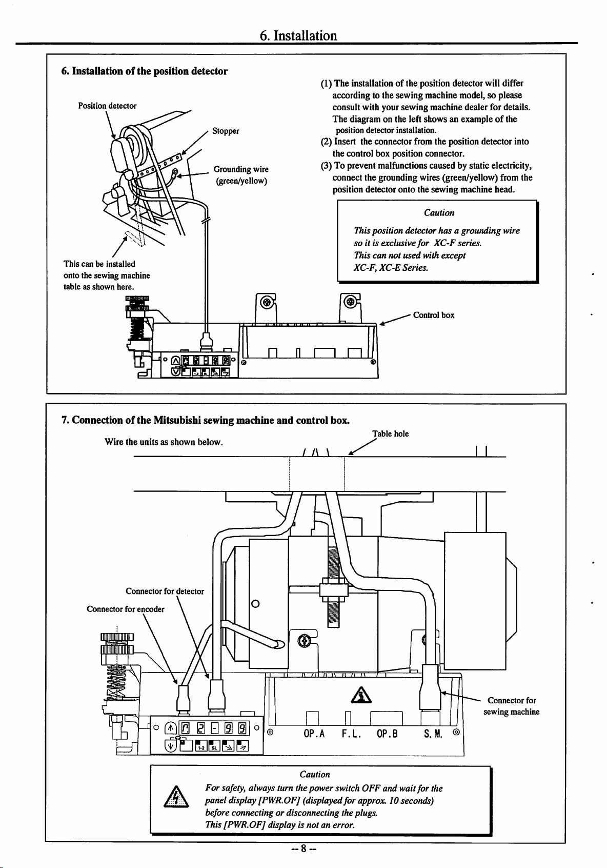
(1)The installation of the positiondetectorwilldi^er
(2) Insert the connector from the position detector into
(3) To prevent malfunctions caused by static electricity,
n n 1 1
11
11
1 . I
according to the sewing machine model, so please
consult with your sewing machine dealer for details.
The diagram on the left shows an exampleofthe
position detector installation.
the control box position connector.
connect the grounding wires (green/yellow) from the
position detector onto the sewing machine head.
Caution
Thisposition detector
so it is exclusive
for
has
a grounding wire
XC-F
series.
Thiscan not used with except
XC-F,
XC-E
Series.
Control
box
r~i
..1
1
7. Connectionofthe Mitsubishi sewing machine
Wire
the
Connector
unitsasshown
Connector
for
encoder
for
below.
detector
and
control box.
/ f\ \
" MIIn
Table
hole
il
t\
Connector
sewing machine
for
°
QIB
El
B i
@1°
Caution
For
safety,always turn the power switchOFF and waitfor the
panel display [PWR.OFJ (displayed
for
approx. 10seconds)
before connecting or disconnecting the plugs.
This[PWR.OFJ display is not an error.
-8-
Page 11
nn
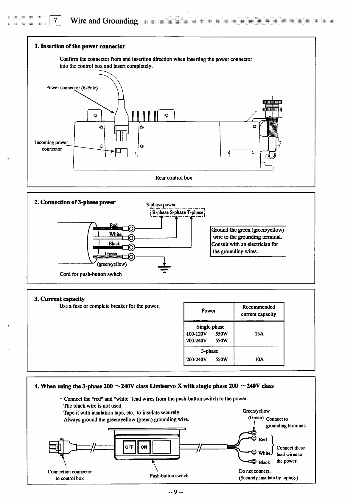
1.
Insertionofthe
Wire
Confimithe connectorfrom and insertiondirectionwheninsertingthe powerconnector
intothe control box and insert completely.
Powerconnector(6-Pole)
and
power
Grounding
connector
Incoming
pow^
connector
2. Connectionof3-phase
Cord for push-button switch
3.
Current
capacity
Use a fuse or complete breaker for the power.
power
White
Black
Green
(green/yellow)
©
Rear
control
3-phase power
j
R-phase
S-phase
box
T-phase
j
Ground the green (green/yellow)
wire to the groimding terminal.
Consult
Power
withanelectrician
the grounding wires.
Recommended
current capacity
for
Single phase
4. When using the 3-phase 200
• Connect the "red" and "white" lead wires from the push-button switch to the power.
The
black
wireisnot
Tape it with insulationtape, etc.,to insulatesecurely.
'^240V
used.
100-120V
2C0-240V
200-240V
class Limiservo X with single phase 200
550W
550W
3-phase
550W
'^240y
Green^ellow
Alwaysgroundthe green/yellow (green)groundingwire.
Connection
to
control
>=?A
connector
box
OFF11 ON
\
Push-button
switch
9-
7;
Do
not
(Securelyinsulateby taping.)
ISA
lOA
class
(Gijeen)
Connect
grounding terminal.
Red
1
I
WhiteJ
Black the power.
connect.
to
Connect
lead
wires
these
to
Page 12
8
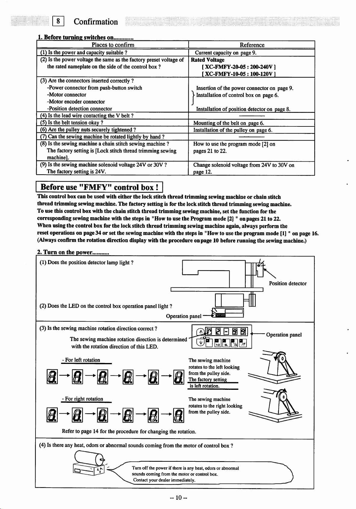
Confirmation
Placestoconfirm
(1) Is the power and capacity suitable ?
(2) Is the powervoltage thesame as thefactory preset voltageof
the rated nameplate on the sideofthe control box ?
Current capacity on page 9.
Rated
Voltage
XC-FMFY-20-05
[
[
XC-FMFY-10-05
Reference
: 200-240V ]
:100-120V1
(3) Are theconnectors inserted correctly ?
-Power connector from push-button switch
-Motor
connector
-Motor
encoder
-Position
(4) Is the lead
(S) Is the belt tension okay ?
(6) Are the pulley nuts securely tightened ?
(7) Can the sewing machine be rotated lightly by hand ?
connector
detection
wire
connector
contacting the V belt ?
(8) Is the sewing machineachain stitch sewing machine?
The factorysetting is [Lockstitch threadtrimmingsewing
machine).
(9) Is thesewing machine solenoid voltage 24V or 30V ?
The
factory setting is 24V.
Before
use
"FMFY"
control
box
!
Insertion of the power connector on page 9.
Installation of control box on page 6.
Installationofposition detector on page 8.
Mountingofthe
Installationofthe pulley on page 6.
beltonpage
6.
How to usethe programmode [2] on
pages 21 to 22.
Change solenoid voltagefrom 24V to 30V on
page
12.
This control boxcan beused witheither the lockstitch thread trimming sewingmachine or chain stitch
thread trimming sewingmachine. The factory setting is for the lock stitch thread trimming sewingmachine.
To use this control box with the chain stitch thread trimming sewingmachine, set the function for the
corresponding sewingmachine with the steps in "How to usethe Program mode [2] " onpages 21 to 22.
When using the control box for the lockstitch thread trimming sewingmachineagain, always perform the
reset operations on page34 or set the sewingmachinewith the steps in "How to use the program mode
[1]
" on page16.
(Always confirmthe rotation direction display withthe procedure onpage10 beforerunning the sewingmachine.)
2.
Turn
on
the
power.
(1) Does the position detector lamp light ?
(2)Does theLEDon the controlboxoperation panellight ?
(3) Is the sewing machine rotation direction correct ?
The sewing machine rotation direction is determined
with
the
For
left
rotation
rotation
directionofthis
LED.
i-i-i-i-l-i
For
right
rotation
Operation panel
J3EZH1
The sewing machine
rotates to the left looking
from the pulley side.
Thefactor^settin^^^
is
left
The sewing machine
rotates to the right looking
from the pulley side.
rotation.
k.
UN
Position
Operation panel
detector
Referto page 14 for the procedureforchangingthe rotation.
(4) Is there any heat,odorsor abnormalsoundscomingfrom the motorof control box ?
Turn off the power if there is any heat, odors or abnormal
sounds coming from the motor or control box.
Contact your dealer immediately.
--
10
Page 13
Adjustments
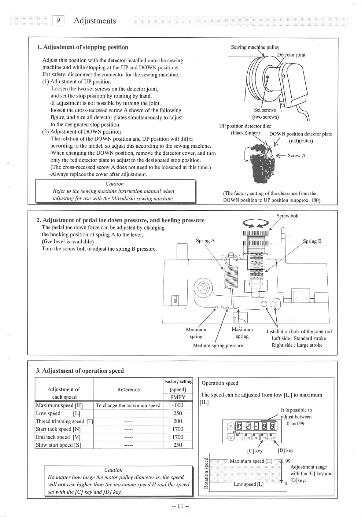
1.Adjustment of stopping position
Adjust this position with thedetector installedonto the sewing
machineand while stopping at the UP and DOWN positions.
For safety, disconnect the connector for the sewing machine.
(1) Adjustment of UP position
-Loosen the two set screws on the detector joint,
and set the stop position by rotating by hand.
-If adjustmentis not possibleby turning the joint,
loosen the cross-recessedscrew A shownof the following
figure, and turn all detectorplates simultaneously to adjust
to the designated stop position.
(2) Adjustment of DOWN position
-The relation of the DOWN position and UP position will differ
according to the model,so adjust this according to thesewing machine.
-When changing the DOWN position, remove the detector cover, and turn
only the red detector plate to adjust to the designated stop position.
(Thecross-recessed screwA does not needto be loosened at thistime.)
-Always replace the cover after adjustment.
Caution
Refer to the sewing machine instruction
adjusting
2.
Adjustmentofpedal
The pedal toe down force can be adjusted by changing
the hooking position of spring A to the lever.
(five
levelisavailable)
Turn
the
for
screw
use with the Mitsubishi sewing machine.
toe
down
pressure,
bolttoadjust
the
springBpressure.
manual
and
when
heeling
pressure
Spring
\
Sewingmachine pulley
Detectorjoint
I
Set
screws
(two screws)
UP position detector disc
(black)(mn^)
(The factory setting of the clearance from the
DOWNpositionto UP position is approx. 180)
A
DOWN
position
^
Screw
Screw
(red)(outer)
bolt
detector
A
Spring B
plate
3.
Adjustmentofoperation
Adjustment
each
Maximumspeed [H]
Low speed [L]
Thread trimming speed [T]
Start tack speed [N]
End tack speed [V]
Slow start speed [S]
No matter how
will not rise higher than the maximum speedH
set
with the
speed
of
[Cj
large
key
speed
Reference
To change the maximum speed
Caution
the motorpulley diameter is, the
and
[Dj
key.
and
FMFY
speed
the speed
oo
Minimum
Medium spring pressure
Operation speed
The speed can be adjusted from low [L.] to maximum
[H.]
Maximum
Installation hole of the joint rod
Left
side:Standard
Right side : Large stroke
It is possible to
adjust between
1 0
qEZHB
[CJkey
" Maximum speed [H]
Low speed [L]
(D) key
stroke
and
99.
Adjustment range
with the [C] key and
[Djkey.
Page 14
101
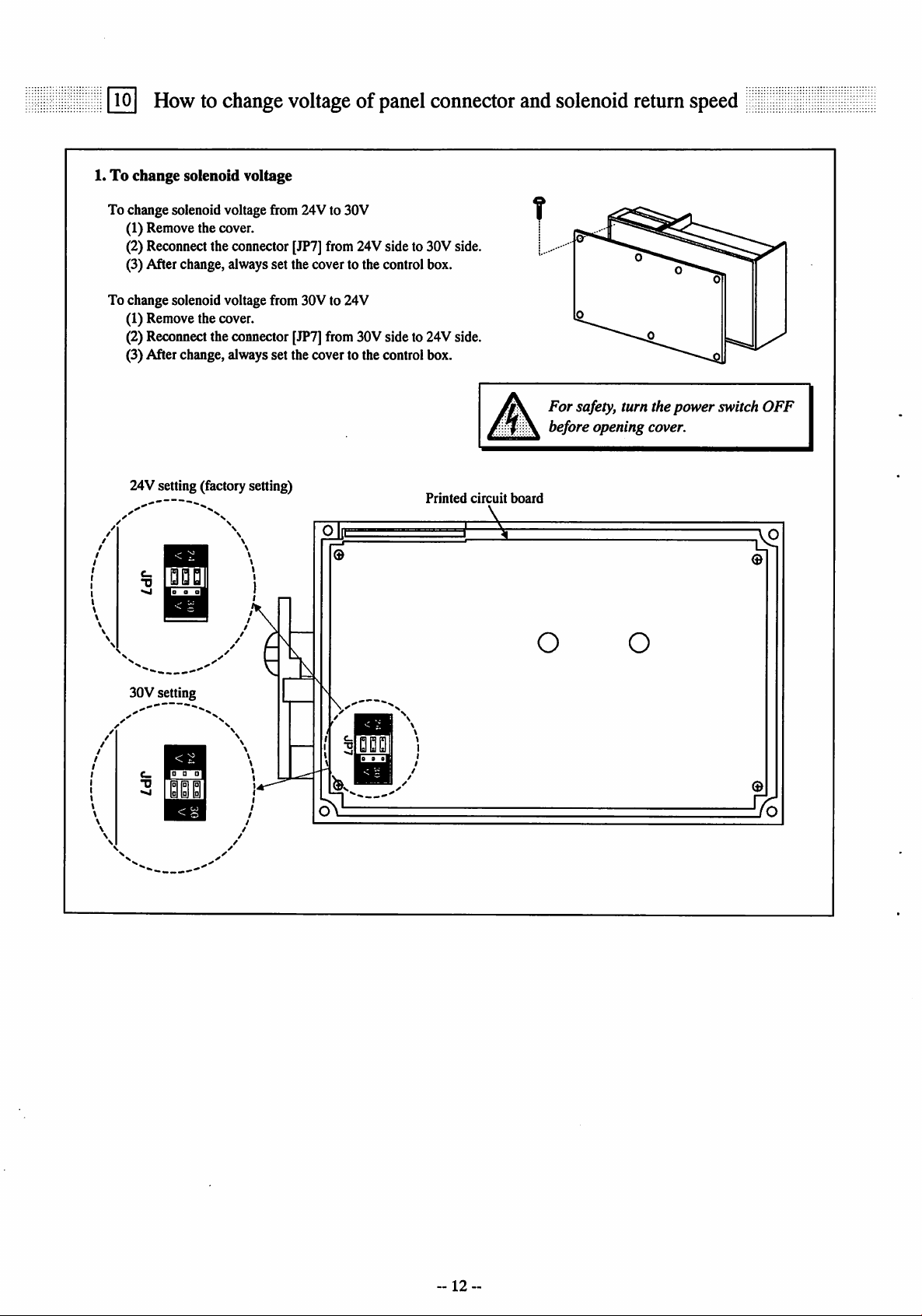
How to change voltage
1.Tochange solenoid voltage
of
panel connector and solenoid return speed
To change soienoid voltage from 24V to 30V
(1) Remove the cover.
(2) Reconnectthe connector[JP7]from 24Vside to 30V side.
(3) After change, always set the cover to the control box.
To change solenoid voltage from 30V to 24V
(1) Remove the cover.
(2) Reconnect the connector [JP7]from 30V side to 24V side.
(3) After change, always set the cover to the control box.
24V setting (factory setting)
Printed
circuit
?
For
safety, turn the
before opening cover.
board
O O
power
switch
OFF
"C
30V setting
-12--
Page 15

lO.Howtochange
voltage of
panel
connector andsolenoid return
speed
2. How to change the outputvoltage DC5V/12V
and
(1) Remove the cover of the optionconnector.
(2)The DCSV/12V can be changedwith the JP3 and JP4
connector on the printedcircuit board asshown the rightfigure.
The 0V/DC5V can be changed with theJP5 connector
on the printed circuit board as shown the right figure.
(3) To change theoutput voltage,pull out the
connector
JP3,JP4
and
reinsertitinto
the
other
side.
[IE3
>
DC
12V
setting
JP5
EE
+5V
OV
OV
setting
(4) The factory setting
Connector
(5) After change, always set the cover to the control box.
JP3
JP4
JP5
Factory setting
DC
12V
DC
5V
OV
DC5Vsetting
[m
+5V
OV
DC5Vsetting
Connector
No. 3 pin of the OptionA
No. 7 pin of the Option B
No. 10 pin of theSewing machine
(Pin
No.)
0V/DC5V
OptionA (Pin No.3)
DC5V/12Vchangeoverswitch
For
safety, turn the power switch
before opening cover.
Do
not change the
from thefactory setting.
Removethe cover of the option connector
JP3
JP4
Sewing machine(Pin No.10)
0V/DC5V changeoverswitch
Option B (Pin No.7)
DC5V/12V changeover switch
Caution
OFF
JPl
and
JP2
3. How to set the switch for increasing the solenoid
(1) Remove the cover.
/^s.
Caution:
For
safety,
turn
return
the
power
speed.
switch
OFF
before
(2) The solenoid return speed can be increased with the setting of the JP6
connector on the printed circuit board as shown on the above hgure.
(3) To change the solenoid return speed, pull out the
connector
and
reinsertitinto
the
FAST
side.
JP6
'-•i .
u.
S|o|-_-l
fT.
^ CO
Normal
settine
^
o
M
(4) Connector factory settings andsolenoid return
Connector
JP6
Cbnnector
factory setting
SLOW
Output during simple setting
Sewing machine connector 3-4 pin output.
(5) Set the connector setting from SLOW to FAST increase the solenoid return speed.
Caution
Thesolenoidreturn speedcannot be increasedifsolenoidoutput chopping duty
OACis return ON in theprogram mode [C].
Theresistance on theprintedcircuit boardwill be burnt out if the solenoid return speed is increased.
This connector must always be turnedON.
If
"UNION SPECIAL"
always
useJP6
[UNI],
[UN2]
and
[UN3]
set
at FAST (solenoid return isfast)
are
setinprogram
mode
opening
FAST
[2],
cover.
ssttine
Solenoid
return
Normal
Output
OA
13"
Page 16

TT]
Operationofthe
Operation
Panel
Keys
1. Displays
When the powersupplyswitch is turnedON, the rotationdirectionwill displayon theLED.Mshownbelow.
When
This state is called the normal mode, and the following keys can be operated.
[t ] Up
The validity of start and end tacking stitch
and
numberofstitches
And the validity and No. of stitches of preset
stitching can be set.
the
key
during
rotation
normal mode
direction
isn't
canbeset.
and
functions of each key
displayedonLED.M,
LED.M
The rotation directionofthe sewing machine is displayed.
The rotationdirection can be changed with the [ ]+[M] keys
press
the[ I ]
key
any
time.
LED.A~D
The stateof the [A] to [D] keys
function setting is shown.
a
frnpniEri
[^ ]
Down
key,
[M]
key
By operating these two keyssimultaneously,
the rotation direction of the sewing machine
can be changed. The display is shown on LED.M.
SL
[B] key
This is used to start sewing with a slow start. After the
power is turned ON and after thread trimming, thesewing
will
start
withaslow
[C]key, [D]key
The speedat which the pedal is
fully toed down is set.
start.
Note
This abovekeyscan beoperatedonly when
the rotary display is shown on the LED.M.
2.
Selectionofeach
Themodescanbe
various basic
(Foreach
(1) Types of program mode
functions
mode
changed
function,
mode
fromthe
andapplication
refer
toa
tableofprogram
Programmode[P] The setting to often use 1 *Sewingmachine, etc.
Program mode [A] The setting tooften use 2 *Servo motor,etc.
Program
normal
Program
Normal
(Therotation direction is
displayed on LED.M)
mode
Program
Programmode[E] H/W checking mode/Recorder ofrunning.
Programmode
[A] key
1 position and 2 position can be selected for the needle
position during stopping.
mode to
functions
mode[B]Thesettingtooften use3 *
mode
mode[D]Tackingsettingmode
various
program
setwiththisoperation
mode
function.)
[C]
In/Out
definition
(I
]Save modeof the setting data
modes
panel.
mode
and
Counter/Speed
(setting
in/output
display,
etc.
signaltofunction,
etc).
Program
Program
Program
Programmode [3] Simple setting modefor other lockstitchsewing machine.
Tacking
mode
mode
[1]
mode
[2]
(condensed
[R]
Reset/returningtooriginal
Simple
setting
mode
Simple
setting
mode
stitch)
mode,
preset
--14
data.(retumtofactory
for
Mitsubishi
forchainstitch
stitching
setting
thread
sewing
trimming
machine.
mode,
pattern
setting)
sewing
select
machine.
mode.
Page 17

11.Operation of the OperationPanel Keys
(2) Selectionof each programmodefrom the normal mode.
a a a
i
Mode
mane
Tacking type
setting mode
No. of tacking stitch
setting
mode
Presetstitching
setting mode
Pattern
No.
selection
Programmode [P]
Programmode [A]
Program mode [B]
Programmode [C]
Program mode [D]
Program mode [E]
Programmode [ I ]
Program mode [R]
Program mode [1]
Program mode [2]
Program mode [3]
mode
Key operation
Press
the[ T] keyonetime
from
the
normal
mode.
Press
the[ T] keytwotimes
from
the
normal
mode.
Press
the[ T]
key
three
times
from
the
normal
mode.
Press
the [ T]key
times
from
While holding down the
[1 ]
key,press
key for 2 seconds or more
from
normal
While holding down the
[ i ]
key,press
key for 2 seconds or more
from
normal
While holding down the
[1 ]
key,press
key for 2 seconds or more
from
normal
While holding down the
[ i ]
key,press
key for 2 seconds or more
from
normal
While holding down the
[ i ]
key,press
key for 2 seconds or more
from
normal
While
holding
key , press the [A] key and
the[T]
key
more
from
While
holding
press
the[t ] keyandthe[B]and
the [C] key and the for 2 seconds
or
more
from
While
holding
key,
press the [B] key and
the[ T] keyfor2
more
from
While
holding
key,
press the [A] key and
the [B] keyfor 2seconds or
more
from
While
holding
key , press the [C] key and
the [D] key for 2 seconds or
more
from
While
holding
key , press the [A] key and
the [D] key for 2 seconds or
more
from
four
the
normal
mode.
the
[T]
mode.
the
[A]
mode.
the
[B]
mode.
the
[C]
mode.
the
[D]
mode.
down
the
for2
seconds
normal
mode.
downthe[i ] key,
normal
mode.
down
the[1]
seconds
normal
mode.
down
the[i ]
normal
mode.
down
the[1]
normal
mode.
down
the[1]
normal
mode.
[i ]
or
or
0 E i 0
Note)
Skipping
about
i S 0 0 0
•
••00
Note)
Skipping
about this n
@ S 0 •
• • @ • 0
i 0 i i i
• • 0 • i
i i • • 0
• • 0 • 0
0 • • • i
• • 0 • 0
• i 0 0 i
• • 0 • 0
0 0 • • i
•
•0EB
•
•BEE
•
•0EQ
0 i 0 B •
•
•0EE
B B 0 B 0
• • 0 • 0
0 i i i •
•
•000
0 i 0 • •
•
•000
0 i i 0 •
15
Q
1-2
Digital display
*The tacking setting mode
willbeentered,
this
n
lenuatthe
*The tacking stitches setting mode
willbeentered.
*The preset stitching setting mode
willbeentered,
lenu
*The pattern No. selection mode
01
willbeentered.
*The display will flicker.
*Theprogram mode [P]will
be
*The display will flicker.
*Theprogram mode [A] will
be
*The display will flicker.
*The program mode [B] will
be
*The display will flicker.
*The program mode [C] will
be
*The display will flicker.
*The program mode [D] will
be
*The display will flicker.
*Theprogram mode [E]will
be
*The display will flicker.
*Theprogram mode [1] will
be
*The display will flicker.
*The program mode [R] will
be
*The display will flicker.
•The program mode [1] will
be
•The display will flicker.
•The program mode [2] will
be
•The display will flicker.
•The program mode [3] will
be
SL
timeofpattern
at the
timeofpattern
entered.
entered.
entered.
entered.
entered.
entered.
entered.
entered.
entered.
entered.
entered.
a
a
Returntothe
normal
mode
Press
[i ]
key any time.
No.=4.
Press
[ I ]
key any time.
Press
[ i ]
key any time.
A to H.
Press
[ i ]
key any time.
While holding
down
[4]
key,
press
[t ]
key.
While holding
down
[1 ]
key,
press
[t ]
key.
While holding
down
[i ]
key,
press[T]
While holding
down
press
While holding
down
press[T]
While holding
down
press
While holding
down
press
Press [D] key
for2seconds
or
Press [D] key
for2seconds
or
Press [D] key
for2seconds
or
Press [D] key
for2seconds
or
[T]
[T]
[T]
more.
more.
more.
more.
key.
[i ]
key,
key.
[i ]key,
key.
[4]
key,
key.
[4]
key,
key.
Page 18

11.Operationof the Operation Panel Keys
3. How to use
To set the functions for Mitsubishi thread trimming sewing machine insimple setting,
(ex.To set forthe LU2-4410-B1T) Functionsetting [410B]
the
program
mode [1]
(Tiin • 0 • •
2)
(Ti|g|
IJIEHEHB
Enter program mode [1].
([i)+[A)+(B]key)
ffllH • i 0 •
* Program mode[1] will be entered.
(TllH
[IIBBEBI5I
*Set function to [410B].
(TllEl
g| • S S
[410B]willflickerwhen [D]key is pressed.
[EIEIHEHI5I
* Press [D] key (2 seconds or more) to return
to
the
normal
mode.
i i @•
• i i •
Description
A) Select the function that conesponds the sewing machine model from "Simplesetting tablefor
Mitsubishi thread trimming sewing machine".
And to press [D] key 2 seconds or more, function will be carried out automatically for that model.
B) To
C)
D) To confirmthe set modelsetting(Simplesettingfunction name)
1)
returntothe
In this case, [410B] will not be set, and the last settings will be used.
Each
time
[280B] [630][280E][FL][N][LOAD].
All contents which were set so far are cleared and the setting speed and the function
setting which corresponds to the chosen sewing machine type are automatically done.
Function-namecorresponding to the sewing machinetype name set dependingon an undermentionedprocedurecan beconfirmed.
yilD
the[ i ]
Note
normal
mode
from
keyispressedinstep
• BHB
the
[410B]
2,the
(The
display,
function
press
the
[ i ]
key
will
changeinorder
factory setting is [280M]. )
while
holding
from
down
[ t ]
key.
[280M][280L][280H]
(310 • II • 0
©BEEEB
* Enter program mode [E].
([i|+[f]
+ [A]key)
* Program mode [E] will be entered.
3)
5)
PIB • • • •
©BBEBB
*
Press
[ t ]
key.
Set
functionto[T].
(TllEI
H
Bl
©BBEBB
* Previous selected simple setting is displayed.
(Ex.
[3750] is displayed.)
glEZHZl
®BBEBB
*
Return
tothe
normal
mode.
( [ 1 ]+ [ t ]
key
)
~16~
Page 19

»4
Function
name
280M
280H
280B
210M
230M
230L
230B
250M
250A
250B
3370
359
3310
3750
6840
6850
410B
430B
4610
4710
4730
630
280E
FL
N
LOAD
11.Operation of the Operation Panel Keys
Simple setting table for Mitsubishithread trimming sewing machine
and motor pulley outside diameter.
Simple setting table for Mitsubishi thread trimming sewing machine
S )eed setting Function setting
Digital
display
eeon
eeoH
eaob
em
eson
esoL
esob
eson
esofi
esob
B310
3SS
BBIO
Bnso
BBHO
beso
'llOb
HBOb
UIO
nnto
HnBO
6B0
eeoe
n
A
LoBd
Sewing machine
type
LS2-1280-M1T(W)
LS2-1280-H1TW
LS2-1280-B1T
LS2-2210-M1T(W)
LT2-2230-M1TW
LT2-2230-L1T
LT2-2230-B1T
LT2-2250-M1TW
LT2-2250-A1T
LT2-2250-B1T
LG2-3370-M1T
DY-359-22BZ
LY2-3310-B1T
LY2-3750-B1T
LY3-6840-B0T
LY3-6850-B0T
LU2-4410-B1T
LU2-4430-B1T
LU2-4610-B1T
LU2-4710-B1T
LU2-4730-B1T
LX2-630-M1
LS2-1280-M1T(W)
♦6
*7
♦8
High speed
(H)
4000
3000
3000
4000
3700
3700
3000
3000
3000
3000
4000
2000
2000
2000
2000
2000
2000
2000
3000
3000
2500
800
5000
5000
5000
*
Low speed
(L)
250
250
250
250
250
250
250
250
250
250
250
250
250
250
250
250
250
250
250
250
250
280
250
250
250
•
Thread
trimming
speed
(T)
200
200
200
200
175
175
175
175
175
175
200
200
225
200
120
120
175
175
175
175
175
160
200
200
200
Start
tacking
speed
(N)
1700
1200
1200
1700
1200
1200
1200
1200
1200 1200
1200
1700
700
700
700
700
700
700
700
700 700
700
700
500 500
1700
1700
1700
* * *
End
tacking
speed
(V)
1700
1200
1200
1700
1200
1200
1200
1200
1200
1700
700
700
700
700
700
700
700
700
700
1700
1700
1700
D
mode
Tack
alignment
(BM)
OFF
OFF
OFF
OFF
OFF
OFF OFF
OFF
OFF
OFF
OFF
OFF
ON
ON
ON
ON
ON
ON
ON
ON
ON
ON
ON
OFF
OFF
OFF
A
brake
mode
weak
(BK)
OFF
OFF
OFF
OFF
OFF
OFF
OFF
OFF
OFF
OFF
OFF
OFF
OFF
OFF
OFF
OFF
OFF
OFF
OFF
OFF
ON
OFF
OFF
OFF
A
mode
gain
selection
(GA)
L
L
L
L
H
H
H
H
H
H
L
L
H
L
H
L
L
L
L
L
L
L
H
L
L
*
Motor
pulley
outside
diameter
(mm)
85
85
85
65
85
65
110
♦2
♦3
*1 Factory setting is [280M].
*2 The effective diameter of the sewing machine pulley is 70 mm.
(Note
:Incaseof
LY2-3310/3750
is80
mm,
LU2-4410/4430/4610/4710/4730
is85
mm.)
*3 [280E]shows setting for theexportation.
*4Afunction
*5Afunction
nameisdisplayedinordertothe
nameisdisplayedinordertothe
directionof4^
direction
oft
every
timeitpresses
every
timeitpresses
a[1]
a[t ]
key.
key.
*6 For sewing machine with foot lifter, without threadtrimmer.
*7 For needle positioner.
*8 It is
possibletoload
(Program
(The
factory
mode
settingof
thesavedsettingdatabythe
[I]: [ i
]+[
t ]+[B] +[C] key)
[LOAD]
is thesettingdataof[280M].)
functionof[SAVE]
--17
--
inthe
program
mode
[ I ].
Page 20

11.Operationofthe Operation Panel Keys
4. Display
Normal
mode
(1)Tackingsettingmode
When
The validity and type of start and tacking can beset here.
and
functions of each key in the tacking mode
Tacking setting mode
♦
Setting of the start tacking
validity and type
* Setting of the end tacking
validity and type
Note)At the time of patternNo.=4(continuoustack),thetackingsetting modewill be skipped.
At the timeof patternNo.=Ato H (programstitching),the presetstitchingmode willbe skipped.
(At
thetime of patternNo.=4,this modewillbeskipped.)
the
[t]
keyisturned
ON,^
will
display
Factory setting
QBQBEIB
No.oftacking
stitch setting
ON
above
the
mode
[M]
key,
and
pattern
and
Setting of tacking type
< Display ex. >
mode, (for lock stitch machine)
(T )key
Preset stitching
ON
setting mode
* Setting of the
preset stitching
validity and No.
111 key
stitches
ON
the
tacking
: No tacking
setting
mode
start
( T] key
ON
Pattern
setting
of
ON
[T1keyON
willbeentered.
tacking
end
tacking
No.
Settingofstart tacking
validity
<Display ex.>
Valid
Invalid
B
Setting of start tacking type
(2) No. of tackingstitches setting mode
When
the
[t]
keyisturned
Q i 0
1-211SL
Setting ofend tacking
validity
<Display ex.>
ON
again,^will
SI
0 B
11
L i
1 i i
T '
No. of stitches A setting.
No.of stitchesB
setting.
No.of stitchesC setting.
Settingofend tacking type
:
Valid
B
:
Invalid
B
display
-Factory
M ^
No. of stitches D setting.
above
the
setting
: V tacking
0
(Once tacking)
: N tacking
(Double tacking)
: M tacking
2
(Triple tacking)
: W tacking
(4 repeattacking)
: 5 repeat tacking
5
: 6 repeat tacking
[M]
key
indicator,
1)
Stnrt
2) When the pattern No.4
Each setting value can be changed from 0 to 9 stitches,
A,B,C,D,E,F
®i'
and
stitches.
B)a
©! '
the
No.ofstitches
^0.4
D),
Ais10
Bis11
Cis12
Dis13
Eis14
Fis15
canbeset.
stitches
stitches
stitches
stitches
stitches
stitches
--18
Page 21

11.Operation of the Operation
(3) Presetstitchingsetting mode
1)
When
the
pattern
isthetimeexcept
m 0 • • a 0
pattern
No.4
- Factory setting
I
Start
©
Panel
Keys
tacking
S ) Start
tacking
will start at the position.
N
thatwasin the
tacking
mode
Settingof presetstitching
<Display ex.>
\q\:Valid
2) When the pattern is No.4
| :
Invalid
Q0D00§
Setting of continuous
tack stitching validity
<Display ex.>
0:
Valid
(4) Pattern No. selection mode
When
the
[ T]
Selectingofpreset
Invalid
keyisturnedONagain,
stitching
SettingofNo. stitches N
(0
to 9999 stitches)
•Factory setting
of
Setting
(0 to 9999stitches)
setting,
No. times N
and
the
continuous
pattern
tack
®End
End
tacking
/©I/
0
In the No.of times(N) setting is N=3,thestitchingwill be in
theorderor A,B and C. If the settingis N=5, thestitching
will be in the order of A,B,C,D,C. If the N is 6or more, the
order will be A,B,C,D,C,D
(If N=0, tacking will continue in the order ABCDCD... while
thepedal is presseddown.)
No.
selection
stitching,
program
mode
willbeentered.
stitching
tacking
that
wasinthe
will start at the position.
©1
(pattern
N
©
No.
Ato H).
tacking
mode
1)Displayof presetstitching(Pattern0 to 3)
a B
r-C2^
I I I P \M
L_—IM~2IjSL
2)
Display
ofcontinuous tackstitching (Pattern 4)
a B 0 i 0 a
3) Displayof programstitching(PatternA toH)
aBB0Ea
a. Pattern A through Hcan be set on control panel "XC-E500Y".
So when programming will be changed, use control panel "XC-E500Y".
(Referto technical manualof controlpanel in detail)
Caution
For
safety purposes, always turn off the powerswitch
whenconnecting or disconnecting the control panel.
IS
0 0 i
10
11
II I
—Display of pattern 0.
When pattern 1,2,3, display
show
1,2,3.
show
1,2,3.
_ I
When
control
the
pattern0disappears.
— Displayofpattern A
When pattern B, C, D, E, F, G, H
display show B, C, D, E, F, G, H
panelisconnected,
-
19
Page 22

12
Howtouse
1.
How
to use
No.l To set the functions for chain stitch sewing machine insimple setting
(Ex.toset for the
1)
Enter
the
Simple
program
VC2800,
program
settingofProgram
mode
[2]
VC3800
mode
[2]
class,
([ 1 ]+
"YAMATO")
[C]+[D])
Mode
Function
(Indicates key operation. Refer to Page 15.)
[2]
(for
setting
chain
[YU4]
stitch
trimming
machine)!i
2)
4)
6)
Description
ftllB
B gl
••
[gCHBDHEl
Program mode [2] will be entered.
(T||0 i 0 • •
[YU4]will flickerwhen [D] ispressed.
SinZHWE
(JIBBEBB
Press [D] to return to the normal mode.
3)
iTilB
i B
^EHEEIEI
Set function to [YU4].
5)
SFTZZH
[pEHEE!®
[CLEAR]will be displayedwhen the [D] key is
pressed for approx. two seconds.
A) Selectthe function thatcorrespondsto the sewing machinemodelfor "Simplesetting tablefor
chainstitchsewing
willbecarried
B)To
returntothe
In this case,[YU4] will not be set, andthe last settingswill be used.
C)
Each
time
the
[YU4] [JMH].
Tousethis
HO signal. Junction wiring in detail.
mode,
machine"
out
automatically
normal
[ i ]
keyispressedinstep2,the
pleaseaskyour dealeror lookat
on the page21.
forthat
mode
from
the
model.
[YU4]
Display
(Refer
display,
function
"TECHNICAL
[CLEAR]
tothe
simple
press
the
will
changeinorder
Caution
withthe[D] key,and
setting
table
for
[ T]
key
while
holding
from
[YU2], [YU3],
INFORMATION
functions
"YAMATO"onpage
down
MANUAL
21.)
[ 1].
"about simplesetting,
20-
Page 23

12.Howtouse
Function
name
YU2
YU3
YU4
YU5
NOl
N02
N03
N04
N05
N06
N07
N08
N09
NOA
NOC
NOD
NOE
NOP
PFL
KAl
KA2
KA3
KA4
UNI
UN2
UN3
U345
U346
U348
U347
U160
U16
U362
UFCW
BRl
RMl
SRBI
JMH
*1Afunction
*2 A
Note:
PN
function
Digital
display
Hue
HU3
HUH
HUS
no
no^
no3
noH
noS
no6
noH
noB
noS
noB
noC
nod
no£
nof
PFL
Pn
kPt
kfie
kB3
kPH
Un
Und
Un3
U3HS
U3H6
U3H6
U3Hn
U
160
U
16
U36e
UFCU
br
cOi
Srb
JOH
nameisdisplayedinorder
nameisdisplayed
Please
refertothe
/
t
1
1
Simple
setting of
Program
Mode
[2]
Simple setting table for chain stitchsewing machine
Simple
setting
table
for
chain
stitch
Sewing
machine
maker
YAMATO
YAMATO
YAMATO
YAMATO
PEGASUS
PEGASUS
PEGASUS
PEGASUS
PEGASUS
PEGASUS
PEGASUS
PEGASUS
PEGASUS
PEGASUS
PEGASUS
PEGASUS
PEGASUS
PEGASUS
PEGASUS
PEGASUS
KANSAI
KANSAl
KANSAI
KANSAI
UNION
SPECIAL
UNION
SPECIAL
UNION
SPECIAL
BROTHER
RIMOLDI
SIRUBA
JUKI
"TECHNICAL
VC2600,VC2700 class Solenoid-operatedunderthreadtrimmer
VC26(X),
VC384SP,2845P,2S40P class Air-operatedunderthreadtrimmerwith air
wiper
Solenoid-operatedunderthread trimmer withsolenoid wiper
W(T)series AJT device
Pneumaticunder threadtrimmerwith pneumatictopcoverthreadtrimmer
electric
W(T)series /UT device
Electric under thread trimmer with electric top cover thread trimmer
FW
W674/UTdevice Super tack
W(T)562-82/UTdevice Angled stitch
Pneumatic under thread trimmer with pneumatic top cover thread trimmer
WS62-82/UT device Angled stitch
Pneumatic under thread trimmer with electric top cover thread trimmer
W(T)600,200series /UT/MS device Condensedstitch
Pneumatic
pneumaticunder thread trimmer with pneumatic top cover thread trimmer
W(T)600 series /UT device Skipless
Pneumatic
W(T)6(K)
Pneumatic
pneumaticunder thread trimmer with pneumaticunder theread trimmer
BLSOO
Forsewing machine with foot lifter, withoutthreadtrimmer
For needle positioner
M, RX series Automatic thread trimmer with solenoid wiper
Dseries Automatic thread trimmer with air wiper
Fseries Air-operatedunder thread trimmer with air wiper
DXseries Air-operatedunder thread trimmer with air wiper
33700,34S00 class Solenoid-operatedunderthreadtrimmer
3480Qskcc
34700class PushandPullair-operatedunderthreadtrimmerwith air wiper
FD3, FD4
MH-481-4-4,
inorderto the
Model name of sewing machine and device
VC2700classAir-operatedunderthread trimmerwithairwiper
under
thread
trimmer
series
/UT
device
under
thread
trimmer
under
thread
trimmer
scries /UT device Stitch lock
under
thread
trimmer
series
class Solenoid-operated underthreadtrimmer
series
—
—
MH-484-4-4
tothe
INFORMATION
direction
direction
class
of I
every
of T
every
MANUAL" for the
timeitpresses
timeitpresses
a[i ]
a [ t ]
(for
sewing
Do
not
Do
not
Do
not
Do
not
Do
not
Do
not
Do
not
Do
not
Do
not
Do
not
Do
not
Do
not
key.
key.
Junction
chain
machine
Needle
position
use
use
use
use
use
use
use
use
use
use
use
use
wiring,
stitch
2
2
2
2
1
2
1
1
1
2
1
!!
!!
!!
1
1
!!
I
1
1
2
2
2
2
2
2
2
!!
!!
!!
!!
!!
!!
!!
!!
2
1
2
2
I/O
trimming
High
speed
[HI
6000
6000
6000
6000
6000
6000
4500
4000
6000
6000
6000
4000
6000
6000
6000
6000
6000
6000
6000
6000
4000
5500
4000
6000
6000
6000
5500
signals
Low
Trimming
speed
m
200 200
200 200
200
200
200
200 200
200 200
200 200
200
200
200
200
200
200
200 200
200 200
250
250 250
250
250
200
200
200
200 200
200
200
200
and
details.
machine)
condensed
speed
m
200
200
200
200
200
200
200
200
200
250
250
250
200
200
200
200
200
200
Start
speed
[N1
1400
1400
1400
1400
1400
1400
1400
1400
1400
1400
1400
1400
1400
1400
1400
1400
1400
1400
1400
1400
1400
1400
1400
1400
1400
1700
1700
End
condensed
speed
m
1400
1400
1400
1400
1400
1400
1400
1400
1400
1400
1400
1400
1400
1400
1400
1400
1400
1400
1400
1400
2999
2999
2999
1400
1400
1700
1900
Page 24

131
Howtouse
Simple
settingofProgram
Mode
[3]
(for
lock
stitch
trimming
machine)
I.H0W to use SimplesettingofProgram
No.l To set the functions for the DU RKOPPADLER thread trimming sewing machinein one
step(For
1)
2)
example,
Enter
program
toset for the271class,
mode
[3]
sfEZWwn
[JEIEBEIEI
Program mode [3] will be entered.
4)
iTiia g a g •
[TjEEEH®
[D271]willflicker when [D]is pressed.
6)
Mode [3] (for lock stitch trimming machine)
([1]+
"DURKOPP
[A]+[D])
ADLER")
(Indicateskeyoperation.Referto page 15.)
3)
Function
miH
©EIHEBB
Set function to [D271].
5)
iTllE]
OBBEE®
[CLEAR]
pressed for approx. two seconds.
setting
a
Fii
E E i B
willbe displayed whenthe [D]key is
[D271]
m n
Description
A)
Select
for
the
the
[D]
B)To
retumtothe
Inthis
C)
Each
[750].
To
use
HO signal.
StEZHHH
[JIBEEBB
Press [D] to retum to the normal mode.
the
model
name
that
correspondstothe
DURKOPP
key,
case,
time
the
this
mode,
Junction
ADLER
andthe
normal
[D271]
[ i ]
keyispressedinstep2,the
please
wiring in detail.
thread
setting
ofthe
mode
from
willnotbe set,andthelast
ask
your
trimming
speed
the
[D271]
dealerorlookat"TECHNICAL
and
sewing
sewing
functions
display,
settings
model
machine
machineonthe
willbecarried
name
Caution
press
willbe
will
model
the
[T]
used.
changeinorder
for
the
simple
setting
"Technical
out
key
manual".
automatically
while
holding
from
INFORMATION
MANUAL"about
values
Display
for
that
down
[D697],
[CLEAR]
model.
[i ].
[D271]
with
simple
setting,
22
--
Page 25

13.Howtouse
Simple
settingofProgram
Mode
[3]
(for
lock
stitch
trimming
machine)
Function
name
D697
D271
D273
B715
B716
B737
B740
B757
B770
B790
B830
BLT
BLZ
J500
J505
J555
JDL
JDU
JLH
JLUl
JLU2
TlOO
T157
T158
T300
U639
SLH2
457G
457F
591
211A
212A
411U
412U
591V
691A
691B
750
* 1 A
function
*2Afunction
Digital
display
d69n
dent
dens
bn
bnte
bnan
bnno
bnsn
bnno
bnso
6630
bLf
bL:
JSOO
JSOS
J5SS
JdL
JdU
JLH
JLUt
JLUe
r
too
r
ISO
r
150
r300
06
39
SLHe
Hsnc
Hsnf
991
et
e
ten
Ht
Hteu
99
69
69
990
name
name
Simple
setting tablefor
Sewing
machine
maker
DURKOPP
ADLER
dOrkopp
ADLER
dOrkopp
ADLER
BROTHER
/s
BROTHER
BROTHER
BROTHER
BROTHER
BROTHER
BROTHER
BROTHER
BROTHER
BROTHER
JUKI
JUKI
JUKI
JUKI
JUKI
JUKI
JUKI
JUKI
TOYOTA
TOYOTA
TOYOTA
TOYOTA
UNION
SPECIAL
SEIKO
SINGER
SINGER
SINGER
SINGER
to
SINGER
SINGER
to
SINGER
SINGER
tu
SINGER
to
SINGER
tb
SINGER
displayedinorder
is
displayedinordertothe
is
thread
trimming
sewing
machine
Simple setting table for thread trimming sewing machine
Model name ofsewing machine and device
697-15000
class
271-14000.272-14000
273-14000,274-14000
DB2-B705,DB2-B707.DB2-B715cla.ss
DB2-B716-?,DB2-B716-1,DB2-B716-?,DB2-B716-5 class
DB2-B737-l,DB2.B737-3,DB2-B737-5
DB2-B746-5,DB2-B746-7,DB2-B746-8,DB2-B747-5,DB2-B748-5,DB2-
B748-7
class
DB2-B757
DB2-B772,DB2-B774,DB2-B7740,DB2-B778 class
DB2.B790,DB2-B791-3,DB2-B791-5.DB2-B7910-3,DB2-B7910-5,DB2-
B792,DB2-B793-403,DB2-B795,DB2-B798 class
DB2-B837,DB2-B838
LT2-B841-1,LT2-B841-34-T2-B841-5,LT2-B842-1,LT2-B842-3,LT2-
B842-5.LT2-B845,LT2-B8450,LT2-B8480,LT2-B847,LT2-B848,LT2-
B872,LT2-B875,LT2-B8750
LZ2-B852,LZ2-B853,LZ2-B854,LZ2-B856.LZ2-B857 class
DDL-500,DMN-5420NFA-6-WB
DDL-505,DDL-505A,DDL-506,DDL-506A,DDL-506E,DDL-560-5,DDL5600,DLU-5494NBB-6-WB,PLW-1245-6,PLW-1246-6,PLW-1257-
6,PLW-1264-6,PLW-1266-6
DDL-555-2-2B,DDL-555-2-4B,DDL-555ON.DDL-5570,DDL-5571,DDL-
5580
class
DLD-432-5,DLD-436-5,DLM-5400N-6,DLM-5400-6,DLN-415-5,DLN5410N-6,DLN-5410-6,DLU-450,DLU-490-5,DLU-491-5,DLU-5490BB-6OB,DLU-5490BB-6-WB,DLU-5490N-6,DMN-530-5,DMN-531-5 class
DNU.241H-5,DNU-241H-6,DSC-244-6,DSC-244V-6,DSC-245-5,DSC245-6,DSC-246-6,DSC-246V-6,DSU-142-6,DSU-144-6,DSU-145-5,DSU-
145-6,DU-141H-4,DU-141H-5,DU-141 H-6,DU-161H-6 class
LH-1172,LH-1180-5,LH-1182-5,LH-1150,LH-1152,LH-11604JI-1162
class
DDL-5560NL-6,LU-1114-5,LU-1114-6,LZH-1290-6 class
LU-2210-6-0B
AD1012AD1012BAD1012G,AD1013,AD1013AAD1013G,AD1020,AD
1102AD1102B,AD1102G,AD1103AD1
S,AD1205,AD1205S,AD1212G,AD1213AD2200,AD5010S
AD157AD157G
AD158,AD158-2.AD158-22AD158A-3AD158A-32w«J)158B-2AD158B-
22>VD158G-2,AD158G-22,AD158-3AD158-32 class
AD3110,AD3110P,AD320-2,AD320-22,AD320-
202AD331AD3310,AD3310P,AD332AD340-2AD340-22,AD340202AD340B-2,AD340B.22,AD340B-202,AD341-2,AD341-22AD341-
202AD345-2AD345-22,AD345-202AD352
Class 63900 Solenoid-operatedneedle feed under trimmer
SLH-2B
457 Wiper
457 Thread pull
591,
1591
211A
212A
411U
412U
591V
1691D250
1691D210,1691D200
750
tothe
class
class
class
direction
direction
class
class
class
of I
of t
class
class
class
every
every
class
103AAD1202AD1203,AD1204
class
timeitpresses
timeitpresses
a[i ]
a[T]
class
key.
key.
Needle
position
2
2
2
2
2
2
2
2
2
2
2
2
2
2
2
2
2
2
1
2
2
2
2
2
2
2
2
2
2
2
2
2
2
2
2
2
2
2
High
speed
[H]
1500
3000
3000
4300
3500
4000
2000
5000
4500
3500
3000
3000
3000
5000
4000
4000
4200
2000
2300
2800
3500
3500
4000
3500
1900
4000
570
4000
4000
4000
2300
3500
4000
4500
4000
4000
4000
4500
Low
Trimmin
speed
g speed
[L]
250
170
170
215
215
215 215
215
215 215
215
215
215 215
185
185
200 200
200
200
200 200
200
200
200
200
200
200
200
200
250
100
250
250
250
200
200
250
250
250
250
250
250
150
250
250
215
215
215
215
215
185
185
200
200
200
200
200
200
200
200
200
200
180
100
160
160
200
180
180
180
180
200
200
200
215
Start
tacking
m
speed
[N1
700
1500
1500
1800
1800
1800
1800
1800
1800
1800
1800
1000
1800
1700
1700
1700 1900
1700
1700
1700
1700
1700
1700
1700
1700 1700
1700
1700
1700
1500 1500
1500
1500 1500
1000
1000
1500
1500
1500
1500
1500 1500
1500
End
tacking
speed
fvi
700
1500
1500
1800
1800
1800
1800
1800
1800
1800
1800
1000
1800
1900
1900
1900
1900
1900
1900
1900
1700
1700
1700
1700
1700
1500
1000
1000
1500
1500
1500
1500
1500
Note:
Please refer to the
"TECHNICAL
INFORMATION MANUAL" for the
Junction
wiring,
I/O
signals
--23--
and
details.
Page 26

1.To
1)
14
Howto usethe
change
the
maximum
Enter
program
program
speed
mode
[P]
mode
(Ex.tochangeto4500
([ i ]+[ t ])
(example of
most
rotations) Function setting
frequently
using)
[H.4500]
2)
iTiia a i i i
[SID 0 • • •
[TjEEEBIS
* Program mode [P] will be entered.
ftllD • i • •
* Set to [5].
(TlID
*Setto[0].
8)
Description
A. The setting rangeofthe maximum speed is 0 to 8999 rotations.
B. By pressingeach of the [A],[B],[C] and [D] keys, thesetting value will change between0 to 9.
(However, the [A] key isonly between1 to 8.)
C.The factory setting is [4000rotations].
D. Low speed, thread trimming speed, start tacking speed, end tacking speed, medium speed and slow start speed can be
setinthe
same
• • • i
Return
tothe
manner.
normal
mode([i ]+ [ t
^
])
* Set to [4].
(TlID
♦
Set to [0].
ftiia
Complete the [H] function setting.
• • a •
anal
ooooooooooooooooooooooooooooooooooooooooooooooooooooooooocoooooooooooooooooooooooooooooooooooooooooooooooooooooooco
2. To set
1)
2)
6)
A. This is used for highspeedoperationduringstandingoperations.
B.Thissettingisfirst priority to the keyswitch
C.
the
standing
Enter
work
program
type function setting [AT.ON]
mode
[P]
QFZZZH
IJIBBEBE
* Program mode [P] will be entered.
D D B B
©BBEBIS
* Set to [ON].
Return
tothe
normal
mode([i ]+ [ t
Description
To
turned
ON,it
operates
regardlessofthe pedal stepping quantity.
The
setting
value
will
atthe
alternate
speed
between
([ 1 ] +[ t ])
with
therate
[AUTO]
[OF]
and
[ON]
])
which
wasset
ofoperation
with
--24--
each
diia
B • • •
IJJBEEBE
* Set function to [AT].
iTlia B • B H
©BBEBE
*Completethe [AT] functionsetting.
with
the[C]andthe[D]
panel.
pressofthe
[D]
keyinstep
keyinnormal
5).
(Factory
mode
settingis[OF])
Page 27

14.How to use program mode (example of most frequently using)
3. To operate Half-stitch operation with a backstitching switch .......... function setting [lE.UDS]
Enter
1)
program
mode
[C]([i ]+
[C]
)
2)
[Ei[qWHZH
SEZHZH
DEIEIIDBB
* Program mode[C] willbe entered.
4)
6)
Description
A. Turning ON the backstitching switch connected No.9 pin in sewing machine connector,
if input UDS is turned ON while the sewing machine is running,backstitching (reverse feed) will start.
Half-stitch operation will start if input UDS is tumed ON while the sewing machine is stopped.
B.The setting valuewill be changedwith eachpress of the [D] key in step 4). (Factorysetting is [S7])
Note)
Whenusingthis
ooooooooooooooooooooooooooooooooooooooooooooooooooooooooooooooooooooooooooooooooooooooooooooocoooooooooooooooooo
4. To outputa pulleroutput to spare output
iTiin n H
* Set to [UDSj.
Return
tothe
function,
always
air
normal
mode([i ]+[ T
return
to the
])
normal
modebeforestarting operations.
02
.......... function setting [02.PUL]+[02C.0N] (To set 50% duty)
* Set function to [IE].
©EBBBB
* Complete the
[BE]
function setting.
sewing machine
©©CD
UDS
0—1
OV
Enter
1)
2)
program
QIHTZWH
mode
[C]([i ]+ [C])
ftiiH
g| • • •
-o
©EEEBB
* Program mode [C] will be entered.
4)
fSlD • @i B
5)
©EEEglH
* Set to [PUL].
QIS
S B • •
^ QID • • S 0
®BBEBB
* Set function to [02C].
8)
fTl
0 ^ B 0 0
9)
* Set function to [02].
r?il0 g 0 i •
©BBEB^
* Complete the [02] function setting.
OEEEB®
* Set to [ON].
Returntothe
normal
mode
([ i ] +[ t ])
[gEEEBS
* Complete the [02C] function setting.
Description
A. Select the setting to connect [02] and [PUL].
B.
Spare
output
solenoid
[02] willbe
turned
on,
while
presser
footlifteris
25-
Option B
operated.
®®®
®®®
®(g^®
<S)®®
02
Page 28

14.H0W
5.To set numberof stitches to the needle UP position stop after detecting the fabric end with an optical sensor, etc.
(Ex.
to set to 10 stitches) function setting [C] mode [IA.PSU]+ [P]mode
1)
Enter
to use programmode(example of mostfrequently using)
[PSU.IO]
program
mode
[C]([t ]+ [C])
I 4)
6)
7)
'
SEZZZI
(JIEEEEB
* Program mode [C] will be entered.
SEZZZH
Completethe [lA] functionsetting.
Enter
program
mode
[P]
( [ I ]+[ t ])
SfEWZWE
(JIEBEBB
* Programmode [P]will beentered.
ftiiD
• • m n
(JinEllEISIB
*Set to [1].
fSlD • @
il
i
(JIBEEB®
» Set to [PSU].
5)
Returntothe
normal
mode
([ i ] +[ T])
V
ftllB
g]
Factory
i • •
setting
[IA.PSIJI
®BBEBB
Set function to [PSU].
minnnni
©BBEB®
* Set to [0].
11)
ftiiB i i g 1
(JIBEEHH
* Complete the [PSU]function setting.
Description
A.Setboth[C]
B.
Connect
andphotoelectric sensoris
UP position after 10 stitches and then the thread will be trimmed.
C.
Each
D. The setting range of the number of stitches in 0 to 99 stitches.
E.
Each
I
Connection
example,
( *For
OptionAconnector
(*Please
mode
[IC]
and[P]mode[
photoelectric sensorto No.2pin inoptionAconnector,
turned
time
the
[D]
keyispressedinstep
time
the
[C]
Power
example
lA
supply
read
keyinstep
use
the
Signal
+12V
the
instruction
|
optical
wire
Brown&Pink
9)or
sensor
Black
manual
PSU]
function.
ON,theneedlewillstopat the
3),
the
set
value
[D]
keyinstep
madeinOMRON
(Optical
ofthe
When into
sensor:
optical
10)is
sensor
willbechanged,
pressed,
E3V3-D62.)
light:
E3V3-D62)
for
handling.)
12)
theset
ON
red
green
Needle
(factory
value
Return
tothe
sto
settingis[PSU])
will
change
SENSOR
1) With a
2) Slowly
3) Put a white
(under
The
The
The
The
SENSITIVITY
small
clock
green
red
Increase
red
red
normal
mode([i ] + [ T
Setting of No. of stitches
between
0 to9.
screw
driver,
wise).
LEDisON.
LEDIsOFF.
the
LEDisON.
paper
or material
LED
mustgoOFF.
SETTING
sensitivity.
])
Sensor detection point
set
the
minimum sensitivity,
piece
under
the
sensor.
--
26
Page 29

14.Howtouse
6.To continue presser footlifting after the thread trimming,and to bring down the presser foot
after the time seton the timer has passed function setting [FUM.ON] + [FU.C]
Enter
1)
program
program
mode
[P]
mode
( [ i ]+[ t
(exampleofmost
])
frequently
using)
2)
QfEHZWE
©EHEHB
* Program mode [P] will be entered.
(TlID
♦
Set to [ON].
(Tub i • • •
*
Press
" (TIB 0 • • 0
©EHEHB
* Complete the [FU] function setting.
• • B
[ i ]
key
and
set
function
B"
[FXJj.
(TlBEiPDI
®BBEBB
*Set functionto [FUMj.
ITIB E i 0 0
©BEES®
* Complete the [FUM]function setting.
(TIP • • • B
IJIBEEB®
♦
Set to [Cj.
9)
Returntothe
normal
mode
([ i ]+[ T])
Description
A. Set both [FUM] and [FU] functions.
B. Each timeof the[D] keyis pressedin step 4), the set value will alternatebetween[OF]and [ON],(factorysettingis [OF])
C.Eachtimethe [D]key ispressed instep 7),the setvaluewill
D. the timer time can be adjusted with the FUM timer setting [FCT]in the [C] mode,(factory setting is 12 sec )
oooooooooooooooooooooooooooooooooooooooooooooooooooooooooooooocoooooooooooooooooooooooooooooooooooooooooooooooooo
7. To set needle position higher
Enter
1)
2)
(Tli
program
0 i i i
than
mode
usual
[P]
([ i ]+[ t
after
[JIEEEBB
* Program mode[P] will be entered.
(TIP P P B B
©•EEB^
*
SettoON.
thread
])
change
inorderof
trimming function setting [RU.ON]
[M][C][A][T].
(factory settingis [M])
ITIB E P P P
®BEEBB
* Set function to [RU].
(T
B E P @ B
(^BEEBE
* Complete the [RU]function setting.
6)
Description
A. The motor is reverse runafter thread trimming, and the needle will stop near the needle bar top dead point.
The reverserunanglecan be set in [R8]and the setting range is 0 to 360, and it is2-degree interval.
(factory setting is [30 degree]) [RU] can be set in [P]mode.
B.Thesettingvaluewillalternate
Returntothe
normal
between
mode
([ i ]+[ t ])
[OF]
and
[ON]
witheachpressof [D] keyin 4).(
--27-
factory
settingis[OF])
Page 30

14.How
to use
program
mode
(exampleofmost
frequently
using)
8.To display the rotational speed ofthe sewingmachine be in running function setting
1)
Enter
program
2)
fillil • • • 1
mode
[B]
([i
]+[B])
* Programmode [B]will be entered.
The first function of B mode is a speed display function
of
the sewing machine speed.
[pEEEEIEI
3)
4)
5)
Run the sewingmachine by the pedal toe down.
dili
0 i i i
* For instance, if the maximum speed setting is 4000 rotations,
gCBEBB
When
the
confirmation
Return
tothe
ends,
normal
mode([1]+ [ T
the speed when the pedal is fully toe down
displays [S.4000] as shown in a left chart.
])
[S."*"*"""]
Description
A. The rotational speed of the sewing machine be in running isdisplayed.
B.Whendiffering
oooooooooooooooooooooooocoooooooooooooooooooooooooooooooooooooooooooooooooooooooooooooooooooooooooooooooooooooooo
9.To run without the detector (when the detectoris broken) ........... function setting [NOS.ON]
1)
2)
•>
6)
from
forecast speed,please
Enter
program
mode
[A]
([ i ]+[A])
ftllEI i • • E
1-2 II SL
* Program mode [A] will be entered.
miD
n n a H
ll^ll>y|
IJIEBEBE
•Set
to [ON].
Return
tothe
normal
mode
([ i ]+[ t
confirm
the
maximum
])
speedsetting[H.] of P modeor thespeed
3)
B in D D
©HEEBE
*Set functionto [NOS].
^
(2)
H B
HI
B H
(JIBBBBB
* Complete the[NOS] function setting.
adjustment
of the
normal
mode.
Description
A.
Only
B.
variable-speed
Each
time
the
operation
[D]
keyispressed,
willbepossible.
the
setting
will
Set
position
alternate
stopping
between
[OF]
28
and
~
thread
and
trimming
[ON]
will
notbepossible
Page 31

14.Howtouse
10.To adjusttacking accurately
(1)Toadjust
1)
|_^nter^rogramjT^
"
mia
5)
iTiiei
tacking
(Tosetthestoptimeat each
g • •
*
Program
mode[D] will be entered
0 • •
program
surely
ii
•'
[Dl.
tacking
mode
(exampleofmost
CST]
+ [CT.10]
comerto 100
"
frequently
milliseconds)
|[
miD
Set to [CST]
• B i oi
f^iD • • a B
using)
4)
SEnZZH
*Completethe [Dl] functionsetting
7)
[BIB
B • • i
t-2 II SL
*Set functionto [CT]
Retum
tothe
normal
mode
8)
1
Description
A.Set the type of start/endtackingand the no.of stitchesbefore makingthe abovesetting.
B. For example, to carry out Wtacking, the unitwill stop at each comer for 100 milliseconds
C. Eachtimethe [D] key is pressedinstep3), thesettingwillchangeintheorderof
[M],[D], [CST], [CSU]and [CSD].( factorysettingis [M])
D.Thesetting range of thestop time is 0 to 990 millisecondsin 10-millisecond intervals
The setting display 10 refers to 100 milliseconds, and 20 to 200 milliseconds.
(factory setting isSOmilliseconds)
E. Each time the [C] keyis pressed in the step6), the set valuewill changefrom0 to 9,
andeach time the [D] key is pressed, will change from 0 to 9.
<X><)<X>(X)<X>00<X><X)<XKX><X>0000000<>0<X)0000<X>000<X><X>0<X>0<X><X>00<X)<X>0<>C<KX>0000^^
(2)To aligntackingwhenstart/endtackingspeed is less than 1000 rpm functionsetting[BM.ON]
1)IEnter
program
mode
( [ i ]+ [ T])
[D]
([i]+
[D])"
[BI0 • • • i
Set to [10]
3)
[Bin
©CEBBB
* Program mode [D]will be entered.
[BID
• • 0 0
5)
* Set function to [BM]
ftl E
IqI
D B H
(BEEEHB
*Complete the [CT] function setting
(
Stop
J
.LiIISL
Set to [ON]
Retum
tothe
Description
A.Set
function
B.Setfunction[BM]to [OF]when start/endtackingspeedis
This BMfunction can be used for a rough tacking alignmentof thestart andend tacking.
C. Eachtimethe [D] key is pressed,the settingwill alternatebetween [OF]and [ON].(Thefactorysettingis [OF].)
Note)This function can be used when a stop is not made at each comer when tacking.
Whenthe function setting [Dl. CST] is set, this function setting [BM. ON] will be invalidated.
D. Set to the tack alignment
When "BM" is OFF, the timing of backstitch solenoid tuming ON is one stitch before the setting numberstitches, (as shown below.)
When "BM" is ON, the timing of backstitch solenoid turning ON is the setting numberstitches.
UP
DN
The
[BM]to[ON]whenstart/endtackingspeedis lessthan
N-2
backstitch solenoid operation timing BM
OFF
ON
ll^iLl
normal
mode([i ] +[ T
])
N-1
ON^"
gnBEEB
*Complete the [BM]functionsetting
lOOOrpm
lOOOrpm
J \ ^
or higher.
N
ON
29-
Page 32

14.How
to use
program
mode
(exampleofmost
(3)To set the no. of stitch compensation forstart tackingalignmentBTl
(To
correct
theno.of
advance
stitches
during
start
tacking)
Function
setting
frequently
[BTl.4]
using)
(Ex.)No.of start tackingsetstitches Actualno.of stitches
• A
3
stitches'
3
stitches
Enter
1)
program
mode
[D]
([ i ]+[D])
4
stitches
' I
✓
I
2
stitches
(Note)This no.ofstitchcorrectioncan
be used when a stop is not made
at each corner when tacking.
BT2
.A
2)
4)
[tiia
[J)
* Program mode [D] will be entered.
ao
• • • @
nEEBS
• • • B
5)
©BBBB®
♦
Set to [4]
(TllE
0 • • •
©EBBBB
* Set function to [BTl]
©IB
0 • • 0
©BEBBB
* Complete the [BTl] function setting
14'-
V
BTl
BT3
A
I
'
Vv
I N ^ ^
I
6)
Returntothe
normal
mode
([ i ]+[ T
])
BT4
Description
A. In the above example, the four stitches are used for the start tack advance. This isone stitch more than the no.of stitches
set in the start tacksetting, so reset it so that it is shorter. Set the no. of correction stitches to -1.
The
relation
ofthe no.of
B. With this setting, the advance section will be one stitch shorter, and the retract section will be
increased by one stitch to three stitches. The no. of stitches will be as set.
C. Each time the [D] key is pressed,thesettingwill change in order from0 to 9, A, B, C, D,E, and F.
Setting
value
No.
correction
stitches
E. The no. of correction stitches set in
9
8
of
1
-2
-2
4
F.The no.ofstitchescanbecorrected
Note:
l.When
2.The settingof"BT2" "BT3" and "BT4" is as same as
the
function
7 6
3
-1 —
4
setting
correction
2 1
-1 -1 —
4 4
[Dl.CST]
stitches
BTl
easily
and
setting
valueis
5
4 3 2 1 0
-
-1
is common for the start tack, V tack, Ntack, M tack, and W tack.
by usingthis
isto
adjust
function
tacking
shown
3 2
4
4 4
andthestarttackspeed
surely,
this
"BTl".
below.
1
function
Setthe
+ — + +
0
setting
setting
A
1 2
4
change.
[BTl.*]
value
to[4].
B
c D E F
3 1
4 4 4 4
1
willbeinvalidated.
2
+1
+1
—
30
-
Page 33

14.Howtouse
11. Down counter for bobbin remain thread count (10,000stitches is count over)
[1] Down counter "D" issubtracted at each ten stitches.
[2] When downcounteramount"D" becomezero,sewingwill be prohibited.
[3]
When
the
input
"
ftllD
• @B
program
signal
mode
"11"isturned
Bl
(exampleofmost
on,
down
counter
amount
QEZZZH
frequently
become
"N"
stitch
using)
and
sewing
become
possible.
gJPDEEJlB
*Enter
program
mid5• •
mode
[Cl. ([i ]+[Cl) *
Di
gJEEEHE
*Set to "II" (Input signal) *Set to 'CCD" (Input function)
6)[|Returntothe
"
miD
normahT[iode([
• E
b¥1
i
]+[T])
[IJCEIEEE
Program
mode
"C"willbe
minuihhi
©EBEE^
^1|
"
mim
• • • b
mBBEBB
Enterprogrammode [B]. ([i l+fB])
miH
• • • Di "^miD • i
(^•EEBB
♦
Setto"N"
'^'mia
• • • •
Program mode "B" will be entered
mBOTTO
♦
Setto"1000"
">miD
B i
^EBEHB
•
Setto"D"
Setto"1000"
i¥i
ni
entered.
miQ • E B 0
©EBEHB
* Complete the "H" function setting.
"^miH • i n
mEEEEB
Complete
"imEETWi
[DEBEEB
*
Complete
the
the
"N"
"N"
function
function
setting.
setting,
''>miB 0 0 • •
5JEBEEB
»Setto"CDN"
'^'mEWEnn
5JEBEEB
♦
Setto"DNC"
^'>miEi
0 a
DO
[JjEBEEB
♦
Setto"CNU"
24)
Selection the function on program mode "C".
Selection the function on program mode "B".
Return
tothe
normal
mode([
Description
[Il.CCD]: Inputsignal
[N.1000]: Setthesetting
[D. 1000]: Current Down counteramount
[CDN.ST]:
♦[DSC.
[DNC.ON]: Set "DNC" to "ON"to use down counter.
[CNU.
When
("CNU"
STj:
When
Input
10]:
Ten stitches subtractone count amount.
"11"
amount
stitch
amount
isset
"10",
the
amountofcurrent
signal
"11"
isset to downcounterclear
of up
become
so down
issetto the
"^>miD• •
©EBEE^
♦
">miD
(mEBEE^
»
^^'miD • •
©EBE^^
♦
i ]+[T])
counter
"N".This
"10(K)"
the
amount
counter
down
counter
following
iBi
Setto"ST"
• • a"Bi ^>mi0 a e a a
Setto"ON"
•¥]
Setto"10"
Note) [P] key function selection
[C]mode[IP]=[CCD]:Cleardowncounter
function.
amount
isstart
setby
"CNU",
down
issubtracted ateachtenstitchesinthis
become
zero,
function.
When
--31-
it is
(counterwithcontrolpanel [P] key clearness)
amount
ofdowncount.
counter"D"is subtracted one.
sewing
willbeprohibited.
turned
on,
sewing
'^miB00SB
(T]EBEEB
Complete
©EBEEB
*
Complete
^>miE
[TJEBEEB
* Complete the "CNU" function setting.
example
(Mark
become
)
possible.
the
"CDN"
the
"DNC"
0000
is
factory
function
function
setting.)
setting.
setting.
Page 34

(t)
'Zl
ox
moh
jsoui
jo
3ui|ias uoipuiy
ajduiBxo)
leuSis
'[-37]
'[-31]
uibjSojcI
pae
yCjo)sni
joxia
JOJja
ssn oj
apoa
apoa
Xjojsiq
pi
/Aon
aq) qaaqa
aqj
MaiA
oj
apoui
|nd|no/|ndin
Xpuonb9Jj
[--3>] '[--3'el
(Suisn
(T
(z
(t
*3
aqx
aqx
*
'X3)
aqx
*
'X3)
XBidsip
jaiu3
Elu]
isb]
JOJja
Eim
joua
01
ujniaa
uiBj3ojd
JOJja
X3
3poa
isb]o) pjiqj
g3 apoa
3m
sp®!®
s; apoa
SI
JOJja
SI
ajnSij iq3u aqj uisb si
E B a B
r^nr^n^r^
'paXBfdsfp
('paXBidsip
a B a B
aaaaaffi
SI
apoa
(-paXBidsip
^P®"*
l®^®o
+[I ] +[ t ]) [h]
paXBidsip
([ I ]+[ t ])
aqx
([v]
(e
fe
pjoaaj
*
«
jo
jaquinu
aqx
'X3)
aqx
sauii)
aiuj
JOJja
Bi[T]
apoajojja 'X3)
JOJJ3
£3 apoa
jsbi 01qjjnoj
33
El • a B
SI
SI
JOJja
apoa
El
B a B
SI
apoa joiia jsb] o) puoaas
('paXB[ds!p
Ban
aaai'iyaf^
SIapoa
('paXBjdsip
jaquinu
'paXB|ds!p
'paXBfdsfp
000000000000000000000000000000000000000000000000000000000000000000000000000000000000000000000000000000000^
'[dl] - [vi]
( M +[ I ]+[ t ]) [3]
(I
(Z
Suiwas
^pova
B a •
uopaunj
IB
sibuSis
jndm
qaaqa
ox (z)
jajug
uiBjSojd
Ei[T]
'[NQ]
'[dnl
'[a]
-
[11]
aaaaaffi
'paja}uaaq him[3] apoiuuibj3ojj «
i"®JJ
Suiqoaqo
J®
sibuS}s
P
dtfi
yDitfM
{EE)n
oj
[jq]
IBuSis
jndui
'[dnl
[333]
'[VDH]
8wM3S
9Ultf3DW
8uim9S
[nq]
[nq]
uojjnvj
aoijdo
uaqM
([Vl]
oibjoj
oiBjoj
UOJ)VJ9dO
([ I ]+[ t 1)
i
Dim
XBidsip
aqi
ji
^
siqjj
oj
uaqyw
qoaqo
01
pire
3g
saSuBqo
s| uoiiBjadoaqi
si
aidiUBxa
aqj
qoaqo
aqj
jnf9UV3
'IBuiJOu
IBoSis
oj
jvuSjsai/;
(s
oi
ujnioa
aqi
I^uuou
«
Suimos
joioui
paiag
•IjBqs
U9t{M
sm{
uoijvjsdo^wyjvw
SI
|bu3ispiduiaqi
IjBqs
auiqoBui
J\JO
P^uuni
uoijvpJ
[333] '[V33]
EZnZEJ®
HOaSEl®
aas 01uopounj indui
'NOpsujnj
jaisajj
jassajj
(i'i)
^POON
9P»N
ON
ON
j'nJ
s|qeu^
IOOJ
looj
jf)
lEuSsdois
piSpindoi
Suitiw
^BtSis
jopapQ
nmog)
uojisod
am Xeidsia
iiisd)
ibuSb
uupaads
Vzs)
Smiuiuijjpiwjqx
(is)
JoiJIl
iBUSjs
iaijii
laauBaiaiuuiui pBaiqx
its)
IBuSisSinqaijisjiaBa
(OSd)
(CS) [BuSjsuiu paads moq
(ioi)
(n)
|bu8k u!iapaaN
(on) Suinas
(ON)
XeidsippmSisiapoaug
XBidsip
|bu8b JoiaaiaQ
XE[dsp|bu8!s
(PuSB
OAJO
aSciiOA
OA
JOsSbijoa at]I Xeidsja
JOsSctiOAaqi Xcidsja
(is)
(j)
IBuSts
unop oiojj a|8uc a^i Xeidsia
(Sinuas XjotaBj) (buSb indu|
do|5 Xjuoud uoiiBod
Xiuoud uoi»isodNMOO
(aseqdv)
(as8i(ds) Xeidsip{buSbjspoaua
01
HI
II
dl
01
ai
VI
ai
ai
11
Zl
N
SI
dn
NO
HQ
Qd
lA
ZA
Xe|ds!0
voa
aaa
uopduossQ
•jqSu
psjiM
SI
fBuSis
uaAa
jiji
jndaijoujo
b
nq
pauini
aqjjo
uoijBUBidxa
qoaqo
'jbuSis
indjno/indui
"
Z£
"
3uu|m
•jBuSis
xoq
|0Jiu03
boi
qooqo
oj
aqi
uaqyv;
jnduj
oiqissod
XBjdsip
feuiuud)
si ij -y
aqx
'a
j3q)3qM
[mq]
l,us30p
aqiojjajaj
uioj^
gqi
*jbu3is
Page 35

14.Howtouse
program
mode
(exampleofmost
frequently
using)
(3)Tocheck
1)
2)
4)
5)
output
signal(checkinoperation
Enter
program
mia
* Program mode [E] will be entered.
(T)
BB
mode
[E]
n gi n R
1-2 M SL
ll^ll>y|
5I(B~B1>
)
function
([ i ]+[ t ] +[A])
3)
[pEBEHE
^operatethatthe
Be careful to sewing machine operation when turned ON
the signal which the sewing machine operation has relation
Return
tothe
output
normal
terminal
turned
Caution
mode([1] + [ t
ONandcheck
])
setting
[OAD]-[OFD],
ftl B B
[OlD]-[07D]
51
B B
(JEBEEB
* Select output function to check.
displayisturned
[ON].
Output signal (Factory setting)
Threadtrimming output (T)
Wiper output (W)
Backstitch
Thread release output (L)
Presser foot lifter output (FU)
Virtual output 1
Output for needle cooler (NCL)
TF
output
output
(TF)
(B)
(OTl)
Display
OAD
OBD
CCD
ODD
OFD
OlD
02D
03D
Description
A. It is useful function for check a operation before wiring solenoid.
B. The input terminal refer to the explanationofthe input/output signal.
0000000000000000000000000000000000000000000000000000000000000000000000000000000000000000000000000000000000000000
(4)To checkan output terminal functionsetting[OAO]- [OFO],
(It isturned ON a output terminalwithout sewing machineoperation.)
Enter
1)
2)
fflia
program
mode
[E]
• B 0 0
([ i ]+[ T]+[A])
3)
©ElEEBB
* Program mode[E] will be entered.
4)
ffllH
BHHHI
[010]-[070]
ftl B B B B B
IJjBEEBB
* Select output function to check.
(pEIIEllDEI^
* Output signal is turned ON while pressing the [D] key.
Note) While displaying this function, sewing machinecan not operate.
Return
tothe
normal
mode
5)
( [ I ]+[ t ])
Output signal (Factory setting)
Threadtrimming output
Wiper output
Backstitch output (B)
Thread
Presser
Virtual output 1
Output for needle cooler (NCL)
TF
output (TF)
(W)
release
output
foot
lifter output (FU)
(T)
(L)
(OTl)
Diq>lay
OAO
OBO
OCO
ODO
OPO
OlO
020
030
Description
A. It is useful function for check a wiring.
B. The inputterminal referto the explanationof the input/outputsignal.
~
33
Page 36

13.To
1)
return
14.H0W
all settings to the factory settings ......— function setting [RESET]
to useprogram
Enter
program
mode
[R]
mode
([ i ]+
(example of mostfrequently using)
[B]
+[C])
2)
4)
Description
3)
[T]
EHEEBB
* Program mode [R] will be entered.
sfwhwh
(JIEEESI^
*When the [D] key is held down (for two seconds),
all settings will be returnedto the factory settings.
[RESET]will flicker when the [D] key is pressed.
A.
When
the
normal
mode
willbe
entered
pressing
all settings will be returned to the factory settings.
B.Toreturn
In this case,the settingswill notbe retumedto the factorysetting.
the
normal
mode
from
the
[RESET],
When
thisfunction is set, thecontentsofall settings to thispoint willbecleared,
and willreturnto thefactorysettings. Please takecare
the[D]key
press
Caution
the
[ i ]
when
key
displayed
while
when
[RESET],
holding
usingthis
down
function.
the
[ t ]
key.
-
34
Page 37

14.Howto use program mode(example of mostfrequently using)
14.To set the ON/OFFoperationofthe
(Ex.To stopthe machineby shortcircuiting(ON)the threadtrimmingprotectivesignal(S6).)
Enter
1)
2)
rsiii
program
i • 0 •
mode
[P]
[JCEEBE
* Program mode [P] will be entered.
fSO
• • D 0
thread
([ 1 ]+[ T
trimming protective signal (86) .......... Function setting [S6L.LO]
])
(T||g| i 0 • •
®BBEBB
* Set function to [S6L].
5)
(21111ii• D 0
©CBEBIS
* Set to [LO].
6)
Returntothe
normal
mode
([ I ]+[ t ])
The [S6L]functionsetting has been
completed.
Description
A.The setting valuewill alternatebetween[HI] and [LO] with each pressof the [D] key.
B.Ifthe
C.Ifthe
D. Connection example
E.
logic
changeover
machine
(The
machinewill stop whenthe signal(S6) is shortcircuited(S6turnson).This includestheconstant
shortcircuitstate.(Thespeeddisplay on theoperation
machine stops.)
The
Duringtheother
[NOA]~[NOD],
willstopwhenthesignal(S6)opens(S6turnsoff).Thisincludes theconstant openstate.
speed
display
logic
changeover
simple
setting
[S6L]
on the
operation
[S6L]
valueis[LO]
function
setting
[KAl] ~
ofthe
thread
panel
ofthe
thread
©©©
©(£)©
©®®
Sewing machine
during
function
[YU2]-[YU5],
[KA4],
[UNI],
trimming
willalsostop
trimming
[UN2],
protective
protective
panel
ID(ThreadtrimmingprotectivesignalS6)
settings
[NOl] ~[N09],
and
[UN3]is[HI].
signal
[S6]
when
the
sewing
signal
[S6]
willalsowhenthesewing
1
[NOE],
[HI]setting Stopswhen86 is open.
[LO]
[NOP],
issetto
machine
issetto
setting
[PEL],
[HI],
stops.)
[HI],
[PN],
the
the
Stops
[BRl],
sewing
sewing
when
[RMl],
S6is
short
[SRBl]
circuited.
and
[JMH].
--
35
Page 38

15| To save the setting data
1.
Howtouse
the
program
mode
[ I ]
(SAVE
mode)
To save
1)
3)
A. It is possibleto save thepresentdata intothe
When
B. To
In this case, the settingdata will not be saved.
C.
When
Itis
(The
the
setting
iglID
*Enter programmode [ I
([Jl+[t]+(B]
ftlli
* [SAVE] willflicker when[D] keyis pressed.
Description
the
normal
returntothe
this
[SAVE]
possibletoload
factory
data
• @
J-2
+[C)key)
i B i •
mode
willbe
normal
mode
functionisset,
the
saved
settingof[LOAD]
B'U
entered
from
data
isthe
the
the
bythe
setting
[SAVE]
setting
pressing
function setting [SAVE]
2)
4)
"Simple
selectionof[LOAD]
settingtable".
the[D]
key
when
display,
data
dataof [280M].)
press
willbesaved
the
into
inthe
displayed
[ I ]
©IS
©•BEHE
miB
(TJEBEESI
[SAVE],
key
while
the
[LOAD]onthe
program
i Q B •
*Programmode [ I ] will beentered.
B B i
* Press [D] key (2 secondsor more) to return
to
the
normal
mode.
all
setting
data
willbesaved.
holding
mode
program
[1 ].
down
[ T]
mode
key.
[1].
D.
When
andwillsaveintothe
To
load
the
saved
data
1)
(Din
*Enter programmode[ 1
([iHAMBJkey)
3)
• @•
B @ B D
[TEEEBE
*Set
functionto[LOAD].
5)
iTilE g| B H
this
[SA
VE]
function
[LOAD]
01
il
NOTE
isset,the
newly.
setting
dataof
Pleasetakecare
2)
4)
[LOAD]
when
tothispoint
usingthis
wiltbecleared,
function.
(T||g| @ B
IJIEEEEfS
*Program mode[ 1 ] will beentered.
(T||E @@
*
[LOAD]
willflickerwhen[D] keyis
Bl
bi
•
•
pressed.
*Press[D]key(2 secondsor
to
the
normal
mode.
more)toreturn
--
36
Page 39

To
adjust
the
neutral,
toe
down,
1. How to use the program mode [Q ]
heeling
position
dataofthe
pedal
Toadjusttheneutral, toe
(When the
3)
error
code is
The pedal is neutralized.
Neutral
(Tiib b m
* Program mode [ Q ] will be entered.
5)
fT|[H
* [VCSET] will flickerwhen [D]key is pressed.
down,
"MA".)
s
heeling
B"¥
E
position
dataofthe
2)
4)
6)
pedal
function
setting
[VCSET]
(TilP • E
* Enter programmode [ Q ]
([il+[A]
gPlIB
*Set functionto [VCSET].
rEum
+[C)key)
Bm
0
@i
ETB
0 B
[TjEBBBB
*The display changesinto [START].
(At this point,the neutralposition is memorized.)
7)
9)
B.
Toe down the pedal in the maximum.
(The maximum toe down position is memorized.)
Neutral—*Toe
fflIB
*
Return
tothe
Complete the adjustment
Description
The
neutralofthe internal lever unit, toe down, and the heeling position can be adjusted.
Ifthe
pedal
keepsneutralizing andthe [D]keybe
(At this point,a neutralposition is memorized.)
Afterwards, it is done to toe down and to operate the heeling aboutthe pedal.
(At this time, the maximumtoedown positionand the maximumheelingpositionare memorized.)
It can be done to toe down and to operate the heelingabout the pedal times how many.
Finally,
return
tothe
To
returntothe
In this case, it will not adjust the neutral,toe down, heelingpositiondata of the internallever unit.
normal
gl
normal
normal
downinthe
H
mode
mode
mode
from
maximum
([ i ] +[ T]
pushing
the
[VCSET]
[ i ]
key
)
pushed
key
atthe
display,
8)
inthe state,itchangesintothe
same
time
press
the
Full heeling the pedal in the maximum.
(The maximum heeling position is memorized.)
Neutral—^Full
pushing
[ 1]
key
[ T]
while
key.
holding
heelinginthe
displayof[START]
down
[ f ]
key.
maximum
afterthe
display
blinks.
NOTE
Whenthe position data of the internallever unit isdefective,error "MA"is displayed.
Pleasedo again, the
operating the above-mentionedafter confirming a neutral position of the pedal (lever unit).
memory
of the positiondata of the neutral,toedown and heelingby
37
Page 40

17
Function
Function
name
H.
L
T.
N.
V.
M.
S.
SLN.
h'
SLM.
+
SLP.
SH.
SHM.
e
PSU.
2
u
n
PSD.
S
PS1.
g"
1.
1
PS2.
2.
£
o
PSN.
•g
SEN.
a
pk
SE.
FUM.
FU.
FCT.
FD.
FO.
S3D.
FUD.
PFU.
FL.
Maximum
Low
speed
Thread trimming speed
Start
tacking
End
tacking
Medium
Slow
start
No.ofslow
Slow
start operation mode
Slow
start
One
shot
One
shot
No.ofstitches
No.ofstitches
Sensor
No. of stitches after PSl input
Sensor
No. of stitches after PS2
Restart
Input sensor function
valid/invalid
Setting stitch amount
to
stop
by "SEN"
Presser
FUM operation
Time setting for
Time to motor drive after presser foot
lifter
bring
Full wave time of presser foot lifter output
Delay
time of
Presser foot lifting output chopping duty
Presserfoot liftingoutput when power
is
turned
Cancel the presser foot lifting with full
Function
speed
speed
speed
speed
speed
start
stitches
when
power
operation mode
after
after
input
signal
input
signal
after
PSD.PSU
foot lift
momentary
mode
FUM
down
presser
ON
is turned ON
PSU input
PSD input
PSl
operation
PS2
operation
input
input
PSN
operation mode
foot
signal
mode
mode
S3 input
heeling
SSL.
S2L.
S6L
Cancel presser foot lifting with light heeling
Cancelofthread trimming operation
Threadtriiruningprotectionsignal(S6)
logicalchangeover
AT.
TL.
TLS.
RU.
RB.
IB.
TBJ.
S2R.
IL
TR.
PCS.
PIP.
P2P.
08.
D8.
U8.
KB.
EB.
SB.
SNM.
KD.
KDU.
PSJ.
Automatic
Thread
operation
trimmer
cancel
Auto-stopofpresetstitch sewing before
trim
Reverse run needle lifting after thread
trimming
RU
reverse
run
trimming
angle
with
reverse
feed
mode
Thread
Not
used.
Full heeling, S2 signal operation
Cancel of interlockafter full pedalheeling
Thread
trimming
mode
Thread trimming validity at neutral pedal
Operationwhenpoweris turnedON
during 1position setting
Operationwhenpower is turned ON
during 2 position setting
Needle
stop
position
before
fabric
Needle DOWN position stop angle
Needle UP position stop angle
Reverserun angle from DOWNposition
to UP position
ON
angleofvirtual
ON start
angleofvirtual
"TM"
"TM"
Setting sensor "SEN" input function
Virtual down Setting
Virtualwidthof up and down signal
Not
used.
Mo<)c
P01
P02
P03
PO'4
POS
P06
P07
POS
P09
P10
P11
P12
P13
P14
P15
P16
P17
PIS
P19
P20
P21
P22
P23
P24
P25
P26
P2y
P2a
P29
P30
P31
P32
P33
P35
P38
P37
P38
P39
P40
P41
P42
P43
P44
P45
P46
P47
P48
P49
P50
P51
P52
P53
P54
P55
P56
List
i'
2
—
!•
"S
8
p
E
8
§
4*
•S
B
•«<
s?
K
+
a,
5
1,
45
G
s
G
8
k
t2
•8
a
n
Program
:Illt
Program
Program
Function
name
GA.
PDC.
AC.
ACT.
DC.
OCT.
SC.
SCT.
S2M.
PL
MR.
SR.
NOS.
MSP.
STM.
BKT.
BB.
BNR.
BKS.
BKM.
BK.
S.
N.
D.
P.
U.
CUP.
use.
UCM.
UPC.
NXU.
CON.
DSC.
DCM.
DNC.
NXD.
PCM.
PRN.
CNU.
CCI.
PMD.
mode
lilt
[T]+[B]+[Clkey
Function
name
SAVE.
mode [R]
Function
RESET.
mode
Function
280M.
(Reset):[i1-flBl+ICI key
name
[1]
(Mitsubishi
name
LOAD.
Gain high/lowselection
Function
Pedal
curve
Acceleration
Acceleration
Deceleration time simple
Deceleration
S-character
S-character cushion time
time
time
time
cushion
simple
setting
setting
setting
FullheelingS2 signal operation modewhen
power is turned on or after thread trimming
Sewing machine shaft/motor shaft speed
setting selection
Setting motor pulley diameter
Setting sewing machine pulley diameter
No
detector
Motor
First priority
Brake
Weak
Reductionofweak
Weak
Weak
Weak
Display
mode
maximum
time
brake
angle
brake
force
brake
mode
brake
sewing
speed
stop=>speed
brake
speed
control
sound
Down counter setting count amount
Down
counter
display
count
Up
Up
Up
counter
setting
counter
display
counter
the selectionofsetting
count
count
amount
amount
amount
Up counter the selection of counter
operation
Upcounterchangingsewing pattern
Up
counter
valid
/ invalid
Upcounter operation after counting over
Down counterthe selection of setting mode
Down
counter
the
selectionofcounter
operation
Downcounter changingsewing pattern
Down
counter
valid/invalid
Down counter operation after counting
over
Counterconditionturningon power switch
Setting Thread trimming times "N"
Setting
Number
of stitches "N"
Countmodification (to use101,102)
Display condition turning on
Save
modeofthe
Save
Reset
setting
Function
modeofthe setting data
Function
sewing
machine1:li
Function
LS2-1280-M1T(W)
♦
1
Load of the saved setting data
power
data)
l+rAl+IBI kev
mode
switch
Mode
A01
A02
A03
A04
AOS
A06
A07
A08
A09
AID
All
A12
A13
A14
A15
Aie
A17
A18
A19
A20
A21
B01
B02
B03
B04
BOS
B06
B07
BOB
BOO
BIO
B11
B12
B13
B14
BIS
B16
B17
B18
bTs
B20
Mode
Mode
R01
Mode
1-01
1-24
Ml
.
Program mode [2]
Function
YU2.
JMH.
Pj]ogra2.222£J2LL2l££L!2£!i£i!i£!Li£2!iS&S2££!S£2iJtJlI;2JiI21i£L.
Function
D697.
750.
name
name
(Chain
stitch sewing
YAMATO
JUKI
DURKOPP
SINGER
machine):(i]-i-[C]-i-(D]
Function
VC26000,
Function
ADLER
-38--
VC2700
697-45000
class
class
key
Mode
2-01
:
2-34
3-01
3-38
Page 41

Function
name
1# Selection of inputsignal function
IA.~1P.
l#L
IAL.~IPL.
Inputsignal logical changeover function
Function
nL.,I2L.,14l.~I7l.
I#A
IAA.~1EA.,1GA.~IPA.
u
+
14A.~I7A.
-
I#M
o
R#S
e
RFS.,R1S.,B2S.
«2
R#R
o
RFa..BlR.,E2S.
2
R#N
.1
RFN..R1N..B2N.
no.
t
:§
IIP.
3.
I#C
00
e
I1C.,IZC.
s
s
#CT
1CT.,ZCT.
(2
V
PIP.
"S
PIC.
g
PIS.
U
Off
Input signal alternating operation
Setting the function for IF, 11and 12
Set
conditionofRS
Reset conditionofRS F/F for IF, 11 and 12
RS F/F reset stitchamount for IF, 11 and 12
Specialsettingfor inputsignal "11"
(Neglectingof signal)
Special
setting
for
input
RS F/F clear setting
RS F/F delay time setting
Input
signal
11virtual F/F circuit operation 1
Input signal 11 virtual F/F circuit operation 2
Input signal 11 virtual F/F circuit
Selection of outputsignal function
OA.~OD..OF.
01.~07.,0M.~0P.
0#L
Output signal logical changeover function
OAL.~CDL.,OFL.
OiL.~O7L.,0«L.~0PL.
OffC
OAC.~ODC.
01C.~03C.
CWT
OAT.-ODT.
Outputchoppingfunction
,06C.,07C.
Output signal forced OFF function
0IT.~07T.,(»n.~(K>T.
D#
DA.~DD.,DF.
Output signal delay time setting function
D1.-D7.,DM.~DP.
PUD.
PC.
PU.
PC.
POD.
OTT.
POT.
A#.
A1.~A3.
A#L
A1L.~A3L.
A#A.
A1A.~A3A.
N#
N1.~K6.
N#L
N1L.~N6L.
OR.
ORL
ORA.
Rff
R1..B2.
R#L
Presser foot lifter
output
Presser foot lifter FU full
Presser foot lifter FU momentary
Full
wave
output time for
Output chopping duty exceptofFU output
Forced OFF timer setting function for
each
output
FUM operation mode timer setting function
Logic [AND] module
input function selection
Logic[AND]module
setting of Hi
/Low
Logic [AND] module
Alternate
Logic[AND]module
output function selection
Logic [AND] module
settingofHi
Logic
/Low
[OR]
module input function selection
Logic [OR] module setting of Hi
Logic
[OR]
module
Logic [OR] module
output function selection
Logic [OR] module
R1L.,RZL. setting of Hi /Low logic
Variable
speed
CSP.
CSG.
LB.
T#C
T1C.~T3C.
T#T
T1T.-T3T.
D11.
D12.
Variablespeedcommandfor digital input
(Gray
Thread
Virtualoutput (OTl -
function
Forced OFF timer setting function for virtual
outputs
ON delay time setting function forvirtual
output
OFF delay limesetting function for virtual
output
command
code)
release+backstitch
(OTl-OT3)
OTl
OTl
F/F
logic
logic
Alternate
0T3)
for IF, 11
signal"
name
and
11" is ON
operation
chopping
duty
wave
output
mode
each
output
/Low
for digital input
output
forcedOFF
12
time
logic
Mode
C01
:
C02
COS
:
018
:
019
:
020
:
021
059
056
057
:
058
:
059
060
061
3
085
:
088
087
088
:
089
:
0107
0108
0109
0158
0159
0160
Function
name
D21.
D22.
D31.
D32.
CPK.
CP.
•»
CPC.
a
PSW.
u
CKB.
CPB.
C.
D.
E.
CNF.
D1.
D2.
CT.
BM.
BT1.
i!
BT2.
—♦
BT3.
BT4.
"8
BTP.
a
BTO.
as
BTT.
c
CSJ.
2
w
SPN.
43
k
o
fc.
BTM.
S7M.
"8
a
S7U.
o
S7D.
7BD.
ON delay lime setting function for virtual output
OFF
delay time setting function for virtual output
ON delay time setting function for virtual output
OFF delay time setting function for virtual output
Feed pulse output
Setting CP pulse amount
Prohibited angleofoutput
Panel switch operation prohibit
04,
OS output cancel duringbacktack term
CP
output
Speed
setting
Speed setting for the [SPD]
Speed setting for the [SPE] output
F key
functiononcontrol
Operation mode
Operation mode duringstart tack completion
Stop
time
Tack
alignment
No. of stitchcompensation for start tacking alignment
No. of stitchcompensation for start tacking alignment
No.ofstitch compensation for end tacking alignment
No.ofstitch
No.oflacking stitches (+) IS
No.oflacking stitches
Full heeling function immediately after start
tacking
stop
Not
used.
The speed operationmodewhenboth the medium
speed
signal and SSV
Set table typesoftacking
Input signal S7 operation mode during preset stitching
Manual backstitch ON timing 1
Manual backstitch ON timing 2
The OFF timing setting of output B when the
backstitchingsignal
BIN.
The maximum tacking stitches
(maximum
BOO.
TLS.
No. of end tacking stitches
Operationmodeduringthreadtrimmercancel
(CP)
cancel
during
for the
during
at each
comer
compensation
stitches is 99
Function
cancel function
CP pulse
backtack
[SPC]
output
output
panel
tacking
during
for
addition
signal
(87)isOFF
stitches)
during
name
term
start and backtacking
end
tacking
stitches
alignment
function
stitches function
is ON
setting.
direct heeling
signal [TL] setting
BTS.
BS.
BTD.
BD.
PNE.
BZ.
1.-4.
Input signal BTL quick pressing operation
Input signal SB and EB quick pressing operation
Operation when input signal
BTL
is ON
Operation when input signal SB and EB
tacking
OFF
are
set
End tacking cancel mode with input signal PSU
The
buzzerofcontrol
Enor
code
panel
validity
0T2
0T2
0T3
0T3
Mode
C201
C202
C203
C204
C205
C206
C207
C208
C209
C210
C211
C212
C213
C214
D01
D02
D03
004
D05
006
D07
008
D09
DIG
Oil
D12
013
D14
D15
D16
D17
D18
D19
D20
D21
D22
D23
D24
D25
D26
D27
E01
(The last error code)(Tbe fourth to last code)
0161
0162
0163
0164
0165
0166
0183
0184
0185
0166
0187
0190
0191
0192
0193
0194
0199
0200
P.
M.
a
1#
1A.~1L.,IP.
:
11.,1Z.
Total integration time of
Total
integration
Input display
power
timeofmotor
on
run
14.,15.
:
:
:
ECA.
ECB.
•8
UP. i
a
g)
DN.
3
DR.
ss
J3
PD.
VI.
s
VZ
k
OffD
s
OAD.-ODD.
•8
m.
a
01D.~03D.
Encoder
signal
display
(A
phase)
Encodersignal display (B phase)
Detectorsignal display (UP signal)
Detectorsignal display
(DOWN
Display the angle from down position
Display the voltageofVC
Display the voltage of
VCl
Display the voltage of VC2
Outputsignaldisplay
signal)
06D.,07D.,0PD.
o#o
OAO.-ODO.
OFO.
010.-030.
:
060..070..0PO.
WT.
VL
TP.
DV.
RV.
T.
Solenoid output
Rated
output
display
Voltage display
Model
display
Data
version
Software
No.
version
Display previous
No.
simple
setting
selected.
E05
E06
E07
E23
E24
E25
E26
E27
E28
E29
E30
E31
E32
E42
E43
:
E53
E54
E55
E56
E57
E58
E59
-39"
Page 42

18
How to Use the Option Connector
Variable operation are possible by adding externalsignals to the option connector.
A current of approximately 1.5 mA flows through the switches used forthe input signal, so please use switch for minutecurrent.
1. Connector Layout
XC-FMFY
Control
Lever(White)
Signal
name
ov
IG
m
II
VCl
+12V/f5V)
Presser
foot
lifter
OV
IF
OF
Sewing
machine
Ground
OB
+24V/+30V
OA
OV
ID
OD
+24V/+30V
m
0V/f+5\O
v/+^uv
oc
OptionA(Black)
OV
lA
+12V/f+5V)
IB
04
IC
Encoder
Detector
SI:
S2:
S3:Presser
VCl:
F;
FU+:presser
FU-:
presser
T:
Thread
TL:
Thread
L:
S7:
B:
PSU:Up
PSD:Down
UPW:
NeedleUpposition
SO:
r|^@®
Factory
Run
(Variable
Thread
Variable
presser
Ground
W:
Wiper
trimmer
Thread
Backstitch
Backstitch
position
Low
IS'
Lever
setting
OV
trimming
foot
speed
+12V
OV
foot
foot
lifter
foot
lifter
output
+24V
trimming
OV
release
+24V
OV
+Z4V
OV
+12V
position
speed
_
speed)
lifter
command
input
output
output
output
cancel
output
input
output
stop
input
stop
input
mm
"
(D®
spli^
r®i
(iJgL®
OptionA Footlifter OptionB Sewingmachine
Communication
Control panel
input
input
output
1
2
3
4
_vg
5
6
1
2
+
-
3
4
1
2
3
4
5
6
7
—©——
8
9
10
11
12
—©
1
2
3
4
5
6
Sewing
©
+12V
UPW
0^
®
machine
unit
—ffih
0^"^ 1
§2—
0-^
PSU
max.
40inA
cT D—
PSD
o'-'-D
SI
External
variable
resister
10k
\-y
,
RXDl
RXDO
TXDl
+12V
TDXO
Q
Encoder
EA
EB
+12V
Ground
Detector
OV
Ground
UP
DN
+12V
Lever
VC
+12V
OV
OV
OV
—
—
(internal)
@
/
1
2
3
4
5
6
1
2
3
4
5
6
1
2
3
4
5
6
1
2
3
Note
OV
14
01
VC2
15
11
+5V/(+12V)
+24V/+30V
12
OV
+24V/+30V
02
07
06/CP
03
3 :
Pin
number
13,14
OTl:
VC2:
U :
NCL:
arefortheair
No
Virtual
Variable
No
101:
Virtual
Needle
Needle
No
No
TF:
"TF"
valve
OV
setting
speed
setting
+5V
+24V
lift
OV
+24V
cooler
setting
setting
output,
output
input
signal
output
command
output
(not
forthe
—40—
solenoid
1
2
3
4
5
6
7
8
9
10
11
12
13
14
15
output)
—
VC2
—cm>—
CS5
—
©—
External
variable
->
resister
10k
Q
Page 43

IS.How to Use the Option Connector
2. To use as a standing work type sewingmachine.
Thesewing
machine
canbe usedas astandingworktypesewing
machine
withthefourconnections
belowusing the lever connector.However,take specialcare to theintrusionof noise,and usethe
shortest wiring possible.
(1) When operating with an external variable resistor
(Control
panel
[auto]
andATin[P]
modeisOFF)
Lever(whiteconnector)
OV
Operation
Thread
trimmer
Presser
foot
Variable speed
command
+12V
lifter
1
2
3
4
VCl
5
6
S3
resistor
10k
a
J
•l
h
?
(2) Foroperating witha highspeed
(Control
panel[auto]andAT in [P] modeis ON)
Lever(white connector)
OV
Operation
Thread
trimmer
Presser
foot
lifter
Variable speed
command
+12V
(3) When operation with highspeed and inching
(Controlpanel[auto] and AT in [P] modeis OFF)
(a) When using the lever connector
(b) When using the leverconnector and option connector
1
7
3
4
5
6
S3
Run
(High speed)
Lever(whiteconnector)
OV
Operation
Thread
trimmer
Presser
foot
Variable speed
command
+12V
lifter
1
2
3
4
5
6
D
JL
D: Equivalent to 1S953(NEC)(VR ^30V. IF^ 30mA)
R:
IkQ
1/2Wor higher
Lever (white connector)
OV
Operation
Thread
trimmer
Presser
foot
lifter
Variable speed
command
+12V
OptionA (black connector)
OV
—
—
—
Operation
(low
speed)
1
2
3
4
5
6
1
2
3
4
5
6
S1
SO
Run
(High speed)
Inching
--41-
Page 44

19 Error Display
When the control box detects an error, the error code is flickered on the operation panel display.
Confirm the error code, and investigate with the following table.
Error
PUr.oP
El
E2
E3
E4
E6
E8
E9
M5
MA
code
Probable
cause
Is the power voltage too low?
Is the power supply capacity too small?
Note : Itdoes this display when power supply is turned OFF, but this is not an error.
Is
the
wiretothe
motor
short-circuited?
Is the sewing machine load torque too high?
Is the power voltage too high?
Is the sewing machine inertia too high?
Is
the
connectortothe
motor
encoder
securely inserted?
Are the signals from the motor encoder correct?
Is the sewing machine locked?
Is
the
motor
locked?
Is the motor connector securely inserted?
Are the signals from the motor connector correct?
Is an extraordinary signal inputted? (The signal as it
repeats ON/OFF at the highfrequency.)
Does the noise from outside enter an input signal.
Is theposition detector connector securely inserted?
Are the signals from the detector correct?
(UP/DOWN signal interruption)
Is the solenoid wiring short-circuited?
Solenoid defect (coil defect)
A error of the copy mode using the control panel.
Is the control panel connector securely inserted?
The voltage or the typeof control panel is difference.
The position data of the internal lever unit is defective.
When power supply is turned ON,
the pedal is not neutral position.
Inspectioo
Check the power voltage.
Check the power supply capacity.
Check the motor wiring.
Check the sewing machine.
Check the power voltage.
Lengthen the decelerationtime.
(Refer to DC in [A] mode.)
Check
the
connector
insertion.
Check the encoder signals.
(Refer to [E] mode.)
Check the sewing machine.
Check
the
motor.
Check
the
motor
Check
the
motor
connector
connector.
insertion.
Check the input signal.
Removesanoise
Check
the
Check
the
detector
detector
source.
connector
UP/DOWN
insertion.
signals. (Refer to [E] mode.)
Check the solenoid wiring.
Replace the solenoid.
Check
the
connector
insertion.
Check the voltage and the type are right.
The pedal is neutralized.
(It returns automatically 1 second later.)
Others
The
sewing does
not
run
when
pedal pressed.
the
Are the operation signals from the lever
unit
broken?
Is the fuse for +12V power supply broken?
Probable
cause
Check the lever unit signal.
(Refer to [E] mode.)
Replace the fuse, when the position
detector lamp does not light.
(Refer to item 3.12.)
The sewing
machine
not
does
runatthe
high speed.
It does not displayed 99 in normal mode.
Is the variable speed voltagewith the pedaltoed
down
low?
Is the motor pulley diameter too small?
Change 99 using control box [D]key.
Check the variable speed voltage.
(Refer to [E] mode.)
Check the motor pulley diameter.
(Refer item 9.3.)
The
threadisnot
trimmed
even
with heeling.
The presser foot
lifter output does
not
operate.
Is the thread trimmingsignal(82) from
the
lever
unit
broken?
Is the cancel thread trimmer operation S2L ON?
Is thetrimkey ^ of the
control
switch
panel
Is the light heelingsignal(S3) or the thread
trimmingsignal (S2)from the lever unit broken?
Is the presserfoot lift signal (F) broken?
Is the presser foot output (FU) broken?
42
OFF?
Check the signal S2. (Refer [E]mode.)
Set S2L to OFF. (Refer [P] mode.)
Set the trim key to ON.
Check signals S2 and S3.
(Refer [E] mode.)
Checksignal F. (Refer[E]mode.)
Check FU output. (Refer [E] mode.)
Inspection
Page 45

201
Specifications
Motor
Control
box
-__Vol^e
and
Specincations
Model
name
Voltage
Rated output (W)
Rated torque (N-m)
Rated speed
Maximum speed (rpm)
Weight
Model
mane
Voltage (V)
Speed
control
range
Solenoic
Range of rating Voltage
Ambient
temperature
Ambient humidity
Storage
Position
temperature
Altitude
Weight
detector
Frequency
~—
(V)
(rpm)
(kg)
General purpose
automatic
thread
trimmer
With
sewing
machine
(rpm)
With
motor
shaft (rpm)
voltage
(kg)
shaft
llOV
single phase
50/60
Hz
XL-554-10(Y)
100to120V
XC-FMFY-10-05
100-120V
XC-KE-OIP
230V single phase,
3-phase 50/60 Hz
550W
1.76Nm(0.18Kgm)
3,000rpm
3,600rpm
8.7
kg
XC-FMFY-20-05
70 to4,000 (MAX 8,999) rpm
50 to 3,600 rpm
DC
24V/30V
±10%
5®C ~
30%~95%
-25'C
Under
(XC-FMFY
~
1000m
3.6
for
Mitsubishi
40®C
55^0
kg
above
mean
sewing
XL-554-20(Y)
200to240V
200-240V
sea
level
machineisoption)
(DC
24V
Setting)
Solenoid
Specifications'"^^^^
Impedance
(Q)
Solenoid
Specifications\.,^^
Impedance
(Q)
Solenoid
Specificalions\.,^^
Impedance
(Q)
Solenoid
Specificatioiis~\,^^
Impedance
(Q)
OF
(Presser foot lifteroutput FU)
8ormore
(continuous
(Thread
(short
(Presser foot lifter output FU)
time
OD
release L)
4ormore
time rating)
OF
10ormore
rating)
(continuous time rating)
OD
(Thread
release L)
5ormore
(short time rating)
OA
(Thread trimming output T)
4ormore
(short time rating)
01
(Virtual
outputl)
4ormore
(short time rating)
(Wiper
(short
(needle
(short
5ormore
time
cooler
5ormore
time
Note 1) Inthe brackets, it is a factory setting.
Note2)The
continuous
time
ratingof"OF"
Note3) Total maximumcurrentis 3.0A.
OA
(Thread trimming output T)
5ormore
(short time rating)
01
(Virtual
outputl)
5ormore
(short time rating)
(Wiper
(short
(needle
(short
5ormore
time
cooler
5ormore
time
Note1) Inthe brackets,it isa factorysetting.
Note
2)The
Note3)Total
continuous
maximum
time
ratingof"OF"
currentis 2.4A.
OB
output
02
output
OB
output
02
output
W)
rating)
output)
rating)
is50
percentageofchopping
W)
rating)
output)
rating)
is50
percentageofchopping
(back
(short
(TP
(short
(back
(short
(TP
(short
OC
stitch
output
4ormore
time
03
output
4ormore
time
OC
stitch
output
5ormore
time
03
output
5ormore
time
B)
rating)
TP)
rating)
duty.
B)
rating)
TP)
rating)
duty.
(Rated
output
currentofvalve
Rated maximum output current
output)
43"
06,
07:
Total maximum current is 0.3A.
Page 46

21
Tableofdigital display and Dimensions
Tableofdigital display
Numeral
Digital display
Character
Digital display
Character
Digital display
Character
Digital display
Dimensions
I
MOTOR
and
0 1 2 3
1
t
0
R
t
U U
CONTROL
B 3
A B C D E F G
c d E
b
K L M N 0 P
1
n n
L
U V w X
II
ti
BOX
_1M
4
H
O
Y
H
5 6
5 5
F
c
0
P 9 r
Z
8 9
7
9
B 9
H
H
t
R S T
5
J
r
MIO
Lever
Unil
Pullev
center
PuDev
cover
A
n n
I—^
n
A MITSUBISHI ELECTRIC CORPORATION
FACTORY
OFFICE
Phone:
AUTOMATION
TOWER
"Z" 14F 9-12
<>81-3-6221-6060
Ichome,
Fax:«ei-3-6221-6076
HaiumI CHUO-KU, TOKYO
SYSTEM
104-6212,
JAPAN
IB<NA)1400004- A(200110)
44
Specifications subject to change withoutnotice.
PrintedinJapan
 Loading...