

Page 1
MITSUBISHI
Mitsubishi
TECHNiCAL
Limiservo
X E
iNSTRUCTION
Series
MANUAL
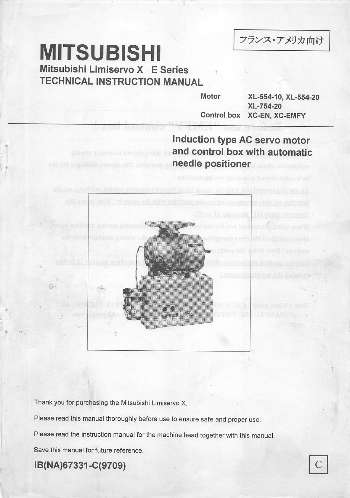
Induction
and
needle
Motor XL-554-10, XL-554-20
XL-754-20
Control
control
box
type
box
XC-EN,
AC
with
XC-EMF=Y
servo
automatic
motor
positioner
Thank
Please read
Please read the instruction manual forthe machine head together
Save
you for purchasing
this
manual
this
manual
for
future
the
Mitsubishi Limiservo X.
thoroughly
reference.
before
use toensure safe and properuse.
with
this manual.
IB(NA)67331-C(9709)
Page 2
Before
use
"EMFY"
control
box!
This control box
can
be used
with
either
the
lockstitch
thread
trimming sewing
machine or chain stitch thread trimming sewing machine. The factory setting is for the
lock stitch
To
use
function
Program
When
always
this
for
mode
using
thread
control
trimming sewing machine.
box
with
the
the
corresponding
121"onpaces
chain
sewing
31to57.
stitch
machine
thread
with
trimming
the
the controlboxfor the lockstitchthread trimming
performthe reset operationson page90or setthe
sewing
stepsin"Howtouse
sewing
machine,
sewing
machine again,
machine with the
set
the
the
steps in "How to use the program mode [1]" on pages 24.
(Always
running
confirm
the
sewing
the
machine.)
rotation
direction
display
with
the
procedure
on
pace
22
before
Note; When using on XC-EMFYCE type, pleaseread the SAFETYTECHNICAL
MANUAL <XC-EMFYCE> thoroughly before use safe
and
proper
use.
/ I
Page 3
nn
Contents
fT]
Safety
[Tl
PointsofCaution'
0
NamesofEach
0
Accessories'
Installation
1.
Installationofthe
2.
Installationofthe
3. Installationofthe
4. Mountingofthe belt
5. Installationoftheprotectivecover
6. Installationoftheposition detector
7.
Connectionoflever
8.
Connection
Wire and Grounding
0
1. Insertionofthepowerconnector
2. Connection
3. CurrentCapacity
4.
When
phase 200~220V class
5.
When
or3-phase200~220VLimiservo Xwith 3-phase220~240V
6. To
Contents
Instruction
ofthe
of
using
die
using
die
change
solenoid outputvoltage
Parts•
motor
control
pull^
unit
connector
Mitsubishi
3-phasepower
3-phase
single
200V
phase
box
sewing
class
100~1
machine
Limiservo
lOV
LimiservoXwith
and
control
Xwidi
box*
single
single
phase
110~'120V
9
•9
9
10
10
12
•12
13
14
14
14
14
15
15
16
0
Confirmation
1. Beforeturningswitc^s
2. Tum on the power
Adjustments
0
1. Adjustment of stoppingposition
2.
Adjustment
ofpedaltoe
3. Adjustmentofoperationspeed
0
Pedal
operation*
Operation ofoperation panel keys
0
1. Display duringnormalmodeand
2.
Selectionofeach
3. Howtouse
4.
Howtouse
5.
Display
and
program
the
normal
functions
(1) Tacking setting mode
(2) No.
of
tacking stitches settingmode
(3) Presetstitchingsetting mode
(4) PattemNo. selection mode
mode
on*
down
mode
mode
ofeach
[1]
key
pressure,
(Simple
function
and
healing
ofeachkey
setting
values
forthe Mitsubishi thread
inthe
tacking
mode
pressure*
andmotor
andpattem
pull^
trimming
mode
diameter
sewing
17
17
18
19
19
19
20
21
22
22
22
•24
machine.)
26
27
27
28
29
30
12
Howto useSimple setting of Program mode
[2]
(forchain stitch trimming machine)*
1. Howto use program mode [2]
2. Simple settingtablefor chain stitchsewingmachine
-1
31
31
'32
Page 4
1.Contents
3. I/O
signalofconnectors
4. Junction wiring 50
5.
Displays
13
How
1. Howtouse
2.
Simple
3. I/O
4. Junction wiring 67
14
Howtochange
1. To
2. Howto
3. How to set the switchfor increasingthe solenoidreturn speed 73
15]
Howtouse
1. To changethemaximumspeed 74
2. To changethe number
3. To applya weekbrakeduringstopping 75
4. To set the standing worktype 75
5. To changeinput/outputport function 76
6. To set external one shot signal 80
7. To set the numberofstitches to the needle UP position stop 81
after detectingthefabric end with an optical sensor, etc.
8. To continuepresserfootlifting aftertrimming,andto bring down 82
the presserfootafterdie time set on timerhas passed
9. Toset
10. To adjustthe correlation betweentoe downangleandspeed 83
11.
To run without detector (When detector is broken) 83
12. To adjust tacking accurately 84
13.
To
14. To checkthe error codehistory and input/output signal 88
15. To retum all settings to the factorysetting 90
16. To set the ON/OFF operationofthe thread trimming protectivesignal 91
and
function
touse
Simple
setting
signalofconnectors
setting
program
tableforlockstitch
voltage
change
solenoid voltagefrom30Vto 24V
change
theoutputvoltageDC5V/12V
program
needle
position
use
the
connector
ofeachkeyin
ofProgram
mode
[3] 58
ofpanel
mode
(exampleofmost
of
stitchesin slow start 74
higher
function
condensed
sewing
connector
than
usual
mode
ai^
stitch
[3]
(for
machine
and
solenoid
frequently
diread
mode
lock
stitch
return
using)
trimming
trimming
speed
machine)
34
57
58
59
61
71
71
71
74
82
86
16 Table ofprogram modefunction 92
17 Table of input/outputfunction for signal on C mode 127
18]
Thecomposition figureofinput and output customization
1. Input and output customization 133
2. Coupling output signal with input inside control unit 134
3. Connector input/output common port 135
19]
Howto usethe option connector 136
1. Connector layout 136
2. The explanation
3. To use as a standing work type sewing machine 139
20
Error
Display 140
21 Specifications 141
22]
Table of digital display and Dimensions 142
of
the input/output signal 137
-2
133
Page 5
0
Safety
Instructions
1.Toensure
•
Always
machine
1.1Beforestarting
-
Read
and
sewingmachine.
1.2Application andpurpose
-
Tbis
applicationsorpurposes.Donot
measures for the installedsewingmachinehavebeentaken.
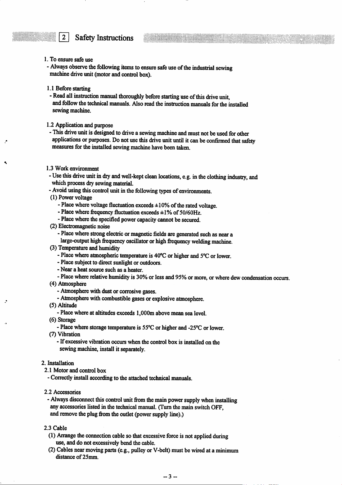
1.3
Work
-
Use
which
-
Avoid
(1) Power voltage
(2) Electromagnetic noise
(3)
(4) Atmosphere
(5) Altitude
(6) Storage
(7) Vibration
safe
use
observe
drive
all
follow
drive
envirorunent
this
process
using
-
Place
- Placewhere
-
Place
-
Place
large-output
Temperature
-
Place
- Placesubjecttodirectsunlightor outdoors.
-
Nearaheat
-
Place
-
Atmosphere
-
Atmosphere
- Placewhereat altitudes
- Place
-
If
excessive vibration occurs when the control
sewing
the
unit
(motor
instruction
the
technical
following
manual
itemstoensure
and
control
thoroughly
manuals.
box).
Alsoreadtheinstruction
imitisdesignedtodriveasewing
use
this
drive
unitindry
dry
this
control
where
voltage
frequency
where
the
where
strong
high
and
where
atmospheric
source
where
relative
withdustor
with
where
storage temperature is
machine,
and
well-kept
sewing
material.
unitinthe
fluctuation
fluctuation
specified
power
electricormagnetic
fi-equency
humidity
temperatureis40°Corhigher
suchasa
humidity
corrosive
combustible
exceeds
install it
separately.
following
exceeds
exceeds
capacity
oscillatororhigh
heater.
is 30%orlessand95%or
gases.
gasesorexplosive
1,000mabovemeansealevel.
55®C
before
drive
clean
±10%ofthe
fields
orhigherand
safe
useofthe
starting
machine
unit
locations,
typesofenvironments.
±1%of50/60Hz.
carmotbesecured.
are
fi^quency
box
industrial
useofdiis
manuals
and
must
sewing
drive
unit,
forthe installed
notbe
used
for
untilitcanbeconfirmed
e.g.inthe
rated
generated
atmosphere.
-25®Corlower.
is installed on the
clothing
voltage.
suchasneara
welding
and
machine.
5°Corlower.
more,orwhere
industry,
other
that
safety
dew
condensation
and
occurs.
2.
Installation
2.1
Motor
and
control
-
Correctly
2.2
Accessories
-
Always
anyaccessories listedin the
and
2.3
Cable
(1)
use, and do not excessivelybendthe cable.
(2)Cablesnear
distanceof25mm.
disconnect
remove
Arrange
install
theplug
the
box
according
this
control
fi^om
connection
moving
parts
to theattached technical
unit
fi-om
the
main
technical
theoutlet
cable
(e.g.,
manual.
Qjower
sothat
pulleyor V-belt) mustbewiredat a
(TurnthemainswitchOFF,
supply
excessive
power
line).)
force
-3
manuals.
supply
isnot
~
when
applied
installing
during
minimum
Page 6
(3)
Confinn
control
box
nameplates
designated
ON/OFF
2.4 Grounding
(1)
Correcdy
2.5
Accompanying
(1)
Electric
safetylow voltage.
2.6
Removal
(1)
Turn
the
line)
before
(2)Donot
(3)
There
isa
at least10
fixim
the
that
the
power
meets
the
specifications
before
connecting
placestosupply
switch
turned
connect
die
appliances
accompanying
main
switch
removing
pullonthe
high
minutes
oudet
cord
voltage
after
(power
2.Safety Instructions
voltageofthe
itto
the
power.
OFF.
control
diemotoror
box
and
accessories
appliances
OFF
and
when
removing
applied
running
supply
remove
inside
line)before
power
cable
ondie
motor
the
power
line.
Perform
this
groundingtothe
and
accessories
the
plug
control
die
the
the
power
box.
plug.
control
switch
opening
for
supplyingtothe
and
control
Connect
power
must
fi"om
Always
itto
step
with
supply
onlybeconnected
the
oudet
hold
box,soalways
OFFand
the
control
box
rating
die
the
power
grounding.
(power
the
plug
wait
remove
box
to
supply
itself.
theplug
panel.
3. Maintenance,inspection and repairs
- Follow the technical manuals for maintenance and inspection
of
this
control
-
Repairs
- Donotrunthis
filterblockedorcloggedwithdust,loosecloth,etc.
-
Always
before
replacing
-
Always
4. Other safety measures
Keep
fingers
V-belt, etc.).
- Donotdropthis
- Donot
-If
-Theuser
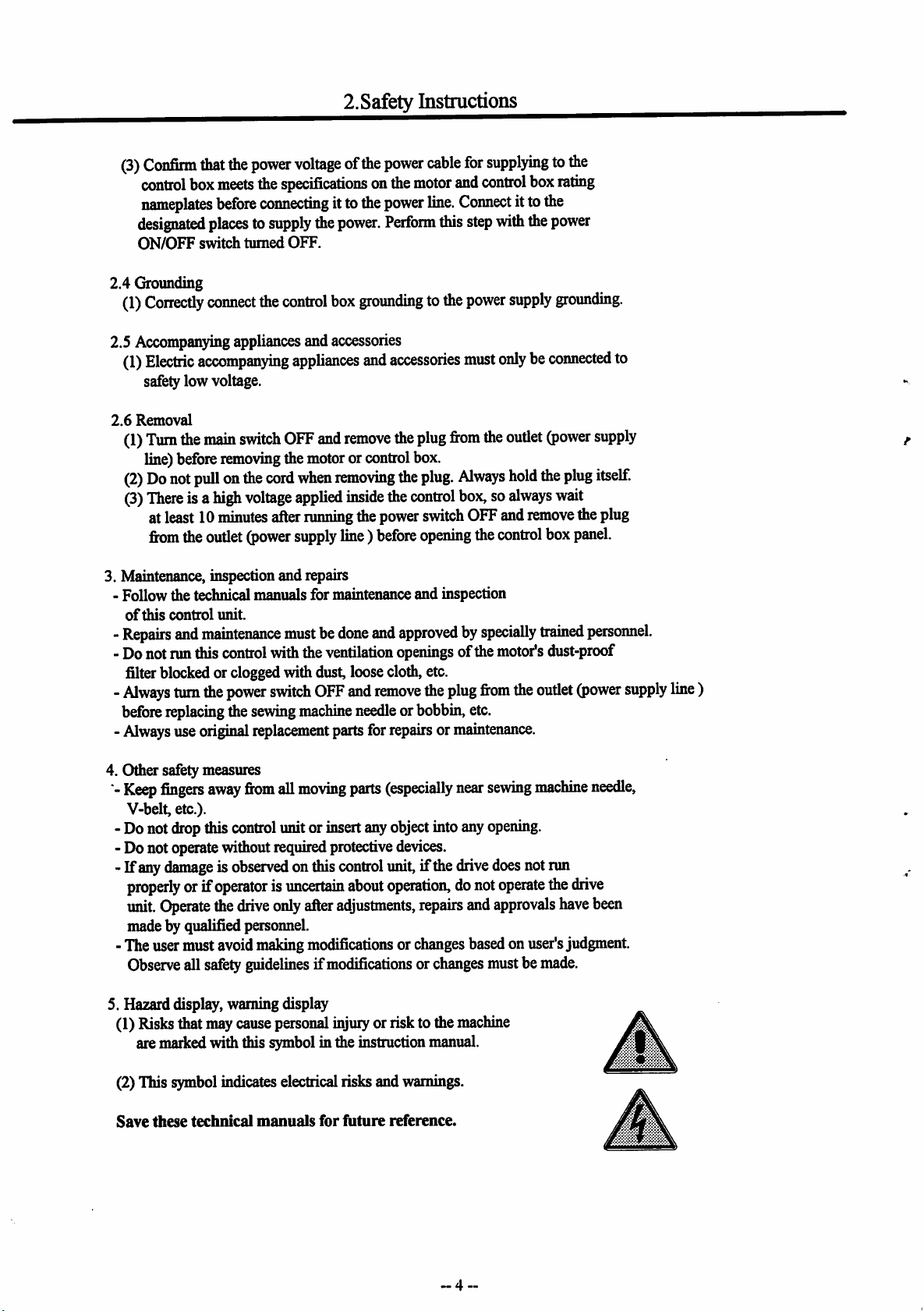
5. Hazarddisplay, warning display
(1)
operate
any
damageisobserved
properly
unit.
Operate
made by qualified personnel.
Observe
Risks
are
marked
unit.
and
maintenance
control
turn
the
power
die
sewing
use
orif
must
all
that
original
safety
replacement
away
fixim
control
without
operatorisuncertain
the
drive
avoid
making
guidelinesifmodificationsorchanges
may
cause
with
tiiis
mustbedone
withtheventilation
switch
OFF
machine
all
moving
unitor
required
onthis
only
after
modificationsorchanges
person^
symbolinthe
and
and
remove
needle
parts
for
parts
insert
any
protective
control
about
adjustments,
injuiyorrisktothe
instruction
approvedbyspecially
openings
orbobbin,
repairsormaintenance.
(especially
object
devices.
unit,
operation,donot
the
plug
intoany
ifthe
repairs
ofthe
etc.
near
drive
and
basedonuser's
machine
manual.
trained
motor's
firom
sewing
opening.
does
operate
approvals
mustbemade.
the
oudet
machine
notrun
dust-proof
the
personnel.
(power
needle,
drive
have
been
judgment.
iT
supply
line
)
(2)This
Save
symbol
these
indicates electrical risksand
technical
manuals
for
future
warnings.
reference.
-4-.
ifSlk
Page 7
1.
Q
Please
Mdien
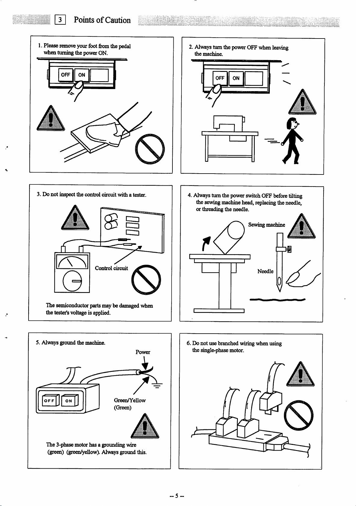
PointsofCaution
remove
turning the powerON.
your
foot
from
the
pedal
2.
Always
the
turnthe
machine.
power
OFFwhen
leaving
OFF
1 I
I
3. Do not inspect the control circuit with a tester.
OFF
ON
M"
1 r
4.
Always
turnthepower
the sewingmachinehead,replacing theneedle,
or threading the needle.
switch
OFF
before
Sewing machine
f
tilting
Control
The semiconductor partsmaybedamagedwhen
the tester'svoltageis applied.
5. Always ground the machine.
OFF
ON
circuit
GreenA''ellow
(Green)
Power
Needle
6. Do not use branchedwiringwhen using
the single-phasemotor.
The 3-phasemotor has a groimding wire
(green) (green/yellow).Always ground this.
Page 8
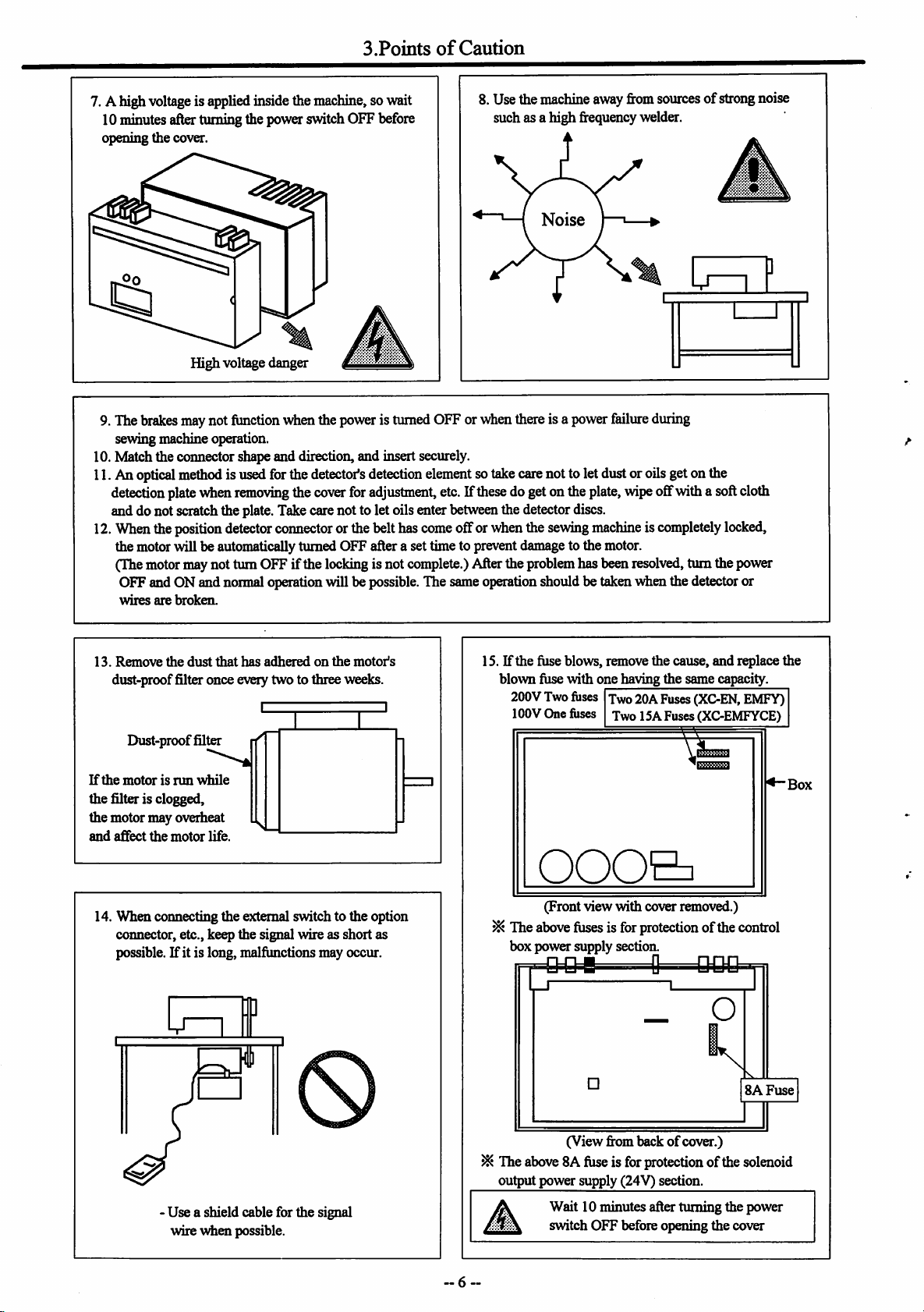
3.Points
of
Caution
7. A highvoltage is appliedinsidethemachine, sowait
10minutesafterturningthe power switch OFF before
opening the cover.
8. Usethemachineawayfromsourcesofstrongnoise
such as a high frequencywelder.
Noise
Lrf
High voltage danger
9.The
brakes
may
not
function
sewingmachineoperation.
10. Match the connector shape and direction, and insert securely.
11.An
optical
method
detection
platevdien
and do not scratchthe plate.Takecarenotto let oilsenterbetweenthedetectordiscs.
12.
When
theposition
the motorwillbe automaticallyturned OFFafter a settimeto preventdamagetothe motor.
(Themotormaynot turnOFF ifthe lockingis not complete.)Aftertheproblemhasbeenresolved, turn the power
OFFand ONand normaloperationwillbe possible. The sameoperationshouldbe taken
wires
are
broken.
isusedforthe
removing
detector
when
the
detector's
the
cover
connector
poweristurned
detection
for
adjustment,
orthebelthas
OFFor
when
there
element
sotakecarenottoletdustoroilsgetonthe
etc.Ifthesedogetonthe
come
offor whenthe
isa
power
failure
plate,
sewing
machineiscompletely
during
wipeoffwitha softcloth
wfren
the detectoror
izzr
locked,
13.
Remove
dust-proof filter once every two to three weeks.
If
the
the filter is clogged,
the motor may overheat
and
affect
14. When coimecting the external switch to the option
coimector, etc., keep the signal wire as short as
possible.Ifit is long, malfunctions may occur.
the
dust
Dust-proof filter
motorisrun
the
vhile
motor
that
life.
has
adheredonthe
motor's
¥
15. Ifthe fuse blows, remove the cause, and replace the
blown fuse with one having the same capacity.
200V
Two
fuses
lOOV
One
Two 20A Fuses (XC-EN, EMFY)
fiises
Two
ISA
Fuses(XC-EMFYCE)
000&
(Frontview
^ Theabovefusesis forprotectionof thecontrol
box power supply section.
•
•B
c
with
cover removed.)
D
•••
_ o
•
SAFuse
Box
(View from backofcover.)
^ The
above
8Afuseisforprotection of the solenoid
output power supply (24V) section.
Use a shield cable for the signal
wire
when
possible.
Wait 10 minutes after turning the power
switch OFF before opening the cover
Page 9
0 0 B a ®
White
Brown
connector
connector
m
voltage
ig plate
for
for
lOOV
200V
Page 10
Q
1.
XC-EMFY
(1)
Worldwide
Accessories
Control
box:
model
Standard
(Type for Mitsubishi sewing machine)
Push-button
Fuse (8A-0ne, 20A-Two)
Control box installation panel,
installation
Junction
Pleasenotethat above
the ordered details or the sewingmachine
wire
switch
screws
accessories
maynot be
set
One
set
One
set
One
set
One
set
enclosed
(The aboveaccessories are for standard type)
(2)SpecialArea model (With detectortype)
Push-button
Detector:
Adapter set for detector
Stopper set for detector
Connector
15P, 12P, 6P,
Fuse (8A-One,20A-Two)
Controlbox installationpanel,
installation
Junction
switch
XC-KE-OIP
set
screws
wire
4P
One
One
One
One
One
One
One
One
set
set
set
set
set
set
set
set
Caution
Always
short circuitthesewingmachine
connector
No.5to6when
the
thread
protection signalS6is not being connected.
(ExcludingJunction settings
[N01J-[N08J,
[NOB],
[YU2]-[YU5],
[NOG],
[KA1J-[KA4],
dependingon
Caution
Alwaysshort circuit thesewingmachine
connector
protection signalS6is
(Excludingfunction settings
[N01]-[N08],
No.5to6when
not
[NOB],
the
thread
being connected.
[YU2]-[YU5],
[NOC],
[KAl]-[KA4],
trimmer
trimmer
[YVIO],
[YVllJ,
[UN1J-[UN3J.)
[YVIO],
[YVll],
[UN1]-[UN3].)
Please
notethat
above
accessories
maynotbe
the ordered details or the sewingmachine
2.
XC-EN
Push-button
Detector:
Control
switch
XC-KE-OIP
box
Adapterset for detector
StoH)er set for detector
Coimectorset
6P
Fuse (8A-0ne, 20A-Two)
Controlboxinstallation panel,
installation
Please
the ordered detailsor the
(Theabove
note
screws
that
above
accessories
accessories
sewing
maynotbe
machine
are forstandard type)
set
One
One
One
One
One
One
One
set
enclosed
set
set
set
set
set
set
set
enclosed
depending on
depending
on
Page 11
3-9
1.
cut
0
Installation
hole
Installation
of
the
motor
159
57
< •:
Table
Belt
hole
2.
Installation
of
the
control
box
(1) Install the two enclosed installation plates
on
the
control
box.
Installation
plate
Bobbin
winder
/
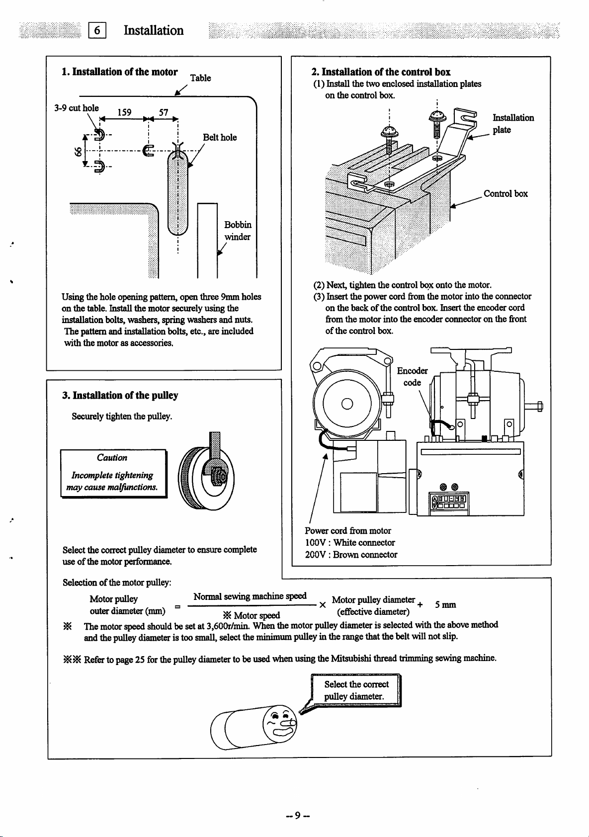
Using the hole opening pattern, open three 9mm holes
on the table, histall the motor securely using the
installation bolts,washers, spring washers and nuts.
The pattern and installation bolts, etc., are included
with
the
motorasaccessories.
3.
Installationofthe
Securely tighten the pulley.
Caution
Incomplete tightening
may cause malfunctions.
pulley
Control
(2) Next, tighten the control box onto the motor.
box
(3) hisertthe power cord fromthe motor into the connector
on
the
from
of
backofthe
the
the
control
motor
into
box.
control
the
Encoder
code
box.
encoder
J
Insert
the
connectoronthe
oimiiaiiu
encoder
cord
front
Power
cord
from
motor
lOOV:
White
Selectthe correctpulleydiameterto ensure complete
useofthe motor performance.
200V:
Brown
connector
connector
Selection of the motor pulley:
Motm:
outer diameter (mm)
^
The
motor
flnH
the
Refertopage25for
pull^
speed
pulley
should
diameter
the
Noimal
besetat
istoo
pulley
3,600r/min.
small,
select
diameter
sewing
machine
^ Motorspeed
When
the
minimum
tobe
used
vdien
the
speed
motor
pulley
using
Motor
puUev
diameter
X „ . . + 0
(enective diameter)
pulley
diameterisselected
inthe
range
the
Mitsubishi
Select
thatthebelt
the
correct
thread
will
trimming
pulley diameter.
~9
. ,
with
mm
the
not
sewing
above
slip.
method
machine.
Page 12
6.
Installation
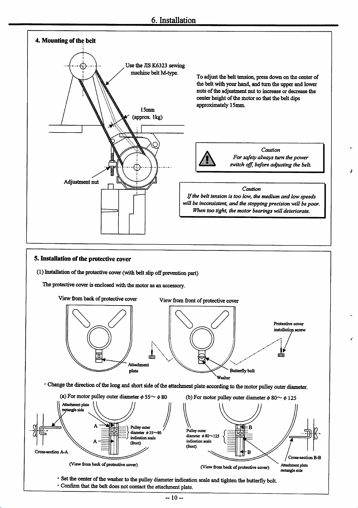
4. Mounting of
Adjustment nut
the
belt
Use the JIS K6323 sewing
machinebelt M-type.
15mm
(approx. 1kg)
To adjust the belt tension, press down on the center of
the belt withyourhand, andturn the upperandlower
nutsofthe adjustment nut to increase or decrease the
centerheightofthe motorsothat the belt dips
approximately 15mm.
Caution
For
safetyalways turn thepower
switch off, before adjusting the belt.
Caution
If
thebelt
tension
is too
low,
the
willbe
When
medium
inconsistent,
too tight, themotorbearingswilldeteriorate.
and thestoppingprecisionwillbepoor.
and lowspeeds
5. Installation of the protective cover
(1)
histallation
The
protective
Change
ofthe
protective
coverisenclosed
Viewfrombackof protective cover
the
duectionofthe
(a) For motorpulley outer diameter0
Attachmentplate
rectangleside
cover
with
long
(with
and
}
Cross-section
A-A
(View
•
Set
the
•
Confirm
from
backof
centerofthe
that
the
belt
protective
cover)
washertothe
does
not
belt
slip
off
prevention
the
motor
asan
accessory.
Viewfromfrontof protectivecover
Attachment
plate Butterfly bolt
short
sideofthe
55~
Pulley
outer
diameter 055'<-'8O
indication
scale
(front)
pulley
contact
the
attachment
0 80
diameter
attachment
part)
Washer
plate
accordingtothe
(b)For motorpulleyouter diameter 0
Pulley outer
diameter
08O~125
indication
scale
(front)
(View
from
backofprotective
indication
scale
and
tighten
the
plate.
motor
pulley
cover)
butterfly
Protective
installation
outer
80~
bolt.
cover
screw
diameter.
0 125
1
Cross-section
Attachrncnt
rectangleside
plate
B-B
-10--
Page 13
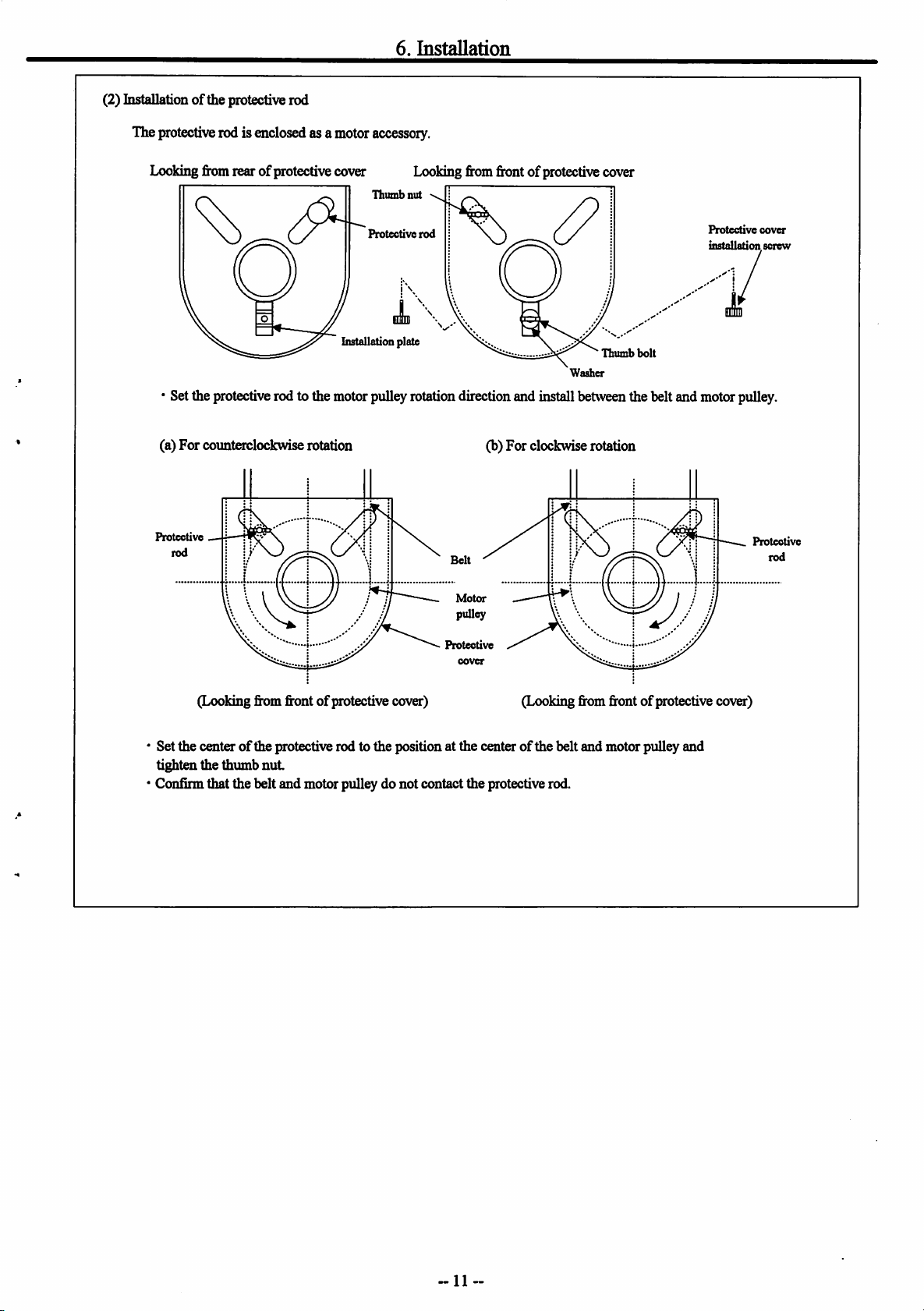
(2) L[istallation of the protective rod
The protectiverod is enclosedas a motoraccessory.
6.
Installation
Looking
fromrearofprotective cover
Installation
Thumb
Protective
Looking
nut
rod
fromfrontof
plate ^ ^ ^ ^
protective
Washer
cover
Protective
installation,
"Thumbbolt
*Settheprotectiverod to the motorpulleyrotationdirectionandinstallbetweenthebelt and motorpulley.
(a)
For
counterclockwiserotation
Protective
rod
(b) For clockwise rotation
Motor
pulley
cover
screw
Protective
rod
Protective
cover
(Looking from frontofprotective cover) (Looking from front
of
protective cover)
Set the centerofthe protective rod to the position at the centerofthe belt and motor pulley and
tighten the thumb
nut
Confirm that the belt and motor pulley do not contact the protective rod.
-11
Page 14
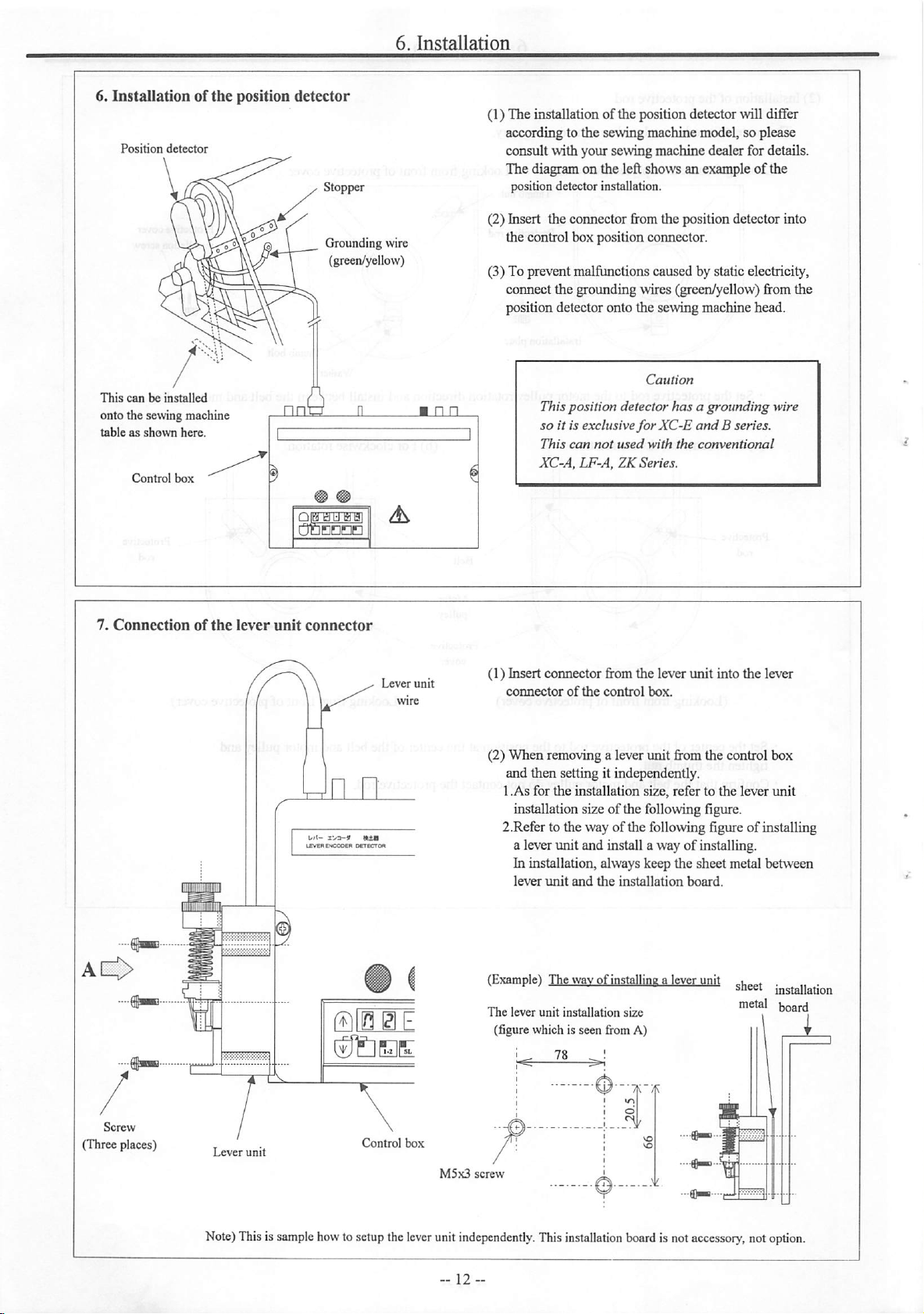
6.
Installationofthe
Position
This
detector
canbeinstalled
onto the sewing machine
tableasshown
Control
here.
box
position
detector
Stopper
Grounding wire
(green/yellow)
(1) The installation of the position detector will differ
according to the sewing machine model, so please
consult with your sewingmachine dealerfor details.
The diagram on the left shows an example of the
position detector installation.
(2) Insert the connector from the position detector into
the control box position connector.
(3) To prevent malfunctions caused by static electricity,
connect the grounding wires (green/yellow) from the
position detector onto the sewing machine head.
Caution
Thisposition detector
so it is exclusive
This
can
not
used
XC-A.LF-A.ZK
has
forXC-E
with
the
Series.
a grounding wire
and
B series.
conventional
7.
Connection
of
the
11
lever
unit
connector
Lever
unit
(1) Insert connector from the lever
connectorofthe
(2)
When
removing a lever
control
unit
into the lever
box.
unit
from the control box
and then setting it independently.
1.As for
the
installation size, refer to
the
lever
unit
installation size of the following figure.
2.Refer to the way of the following figure of installing
a lever unit and install a way of installing.
In installation, always keep the sheet metal between
lever
unit
and
the
installation
(Example) The wav of installing a lever unit „ .
Ti,-
The
u,,-,.
lever
unit
installation
c.;,^
size
(figure which is seen fromA)
board.
sneer
mstallatioo
board
Control
Lever
Note)
unit
Thisissample
how
tosetupthe
box
lever
M5x3
screw
unit
independently.
This
installation
board
is not
accessory,
not
option.
Page 15
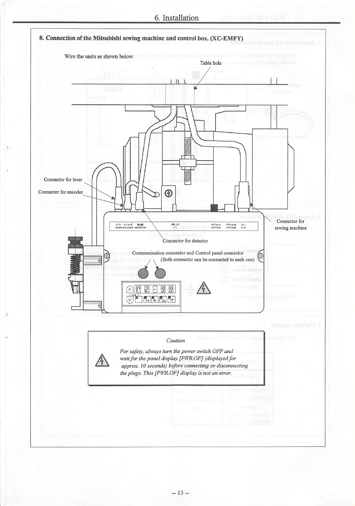
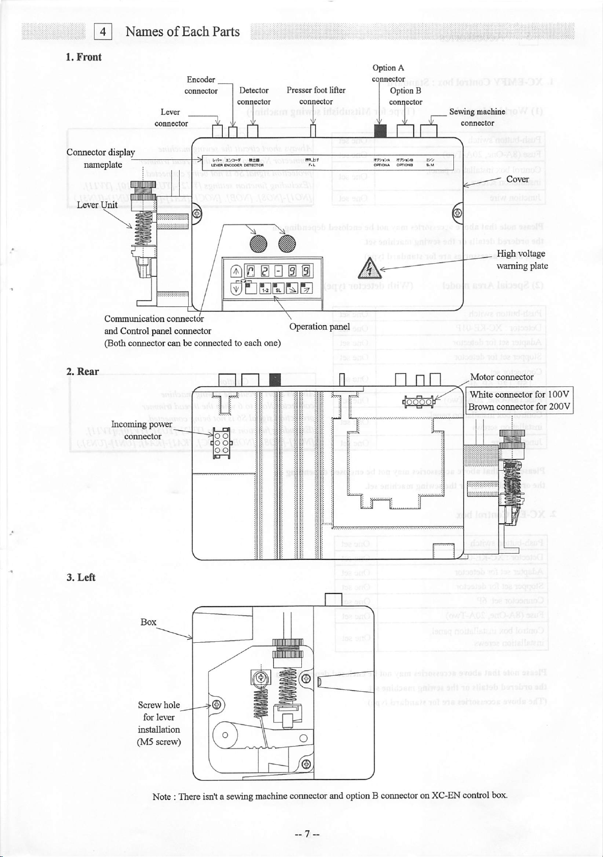
8. Connection ofthe Mitsubishi sewingmachine and control box. (XC-EMFY)
Wire
the
unitsasshown
below.
Table
hole
Connector
Connector
for
for
lever
encoder
Connector
Communication connector and Control panel connector
for
detector
/ \ (Both connectorcan be connected to each one)
WIB @ B i Bl
SJ&SBOE
Caution
For
safety, always turn the powerswitch
wait
for
the
panel
display[PWR.OF] (displayedfor
approx. 10 seconds) before connecting or disconnecting
theplugs. This [PWR.OF] display is not
OFF
an
and
error.
Connector
sewing machine
for
Page 16
pri
Wire
and
Grounding
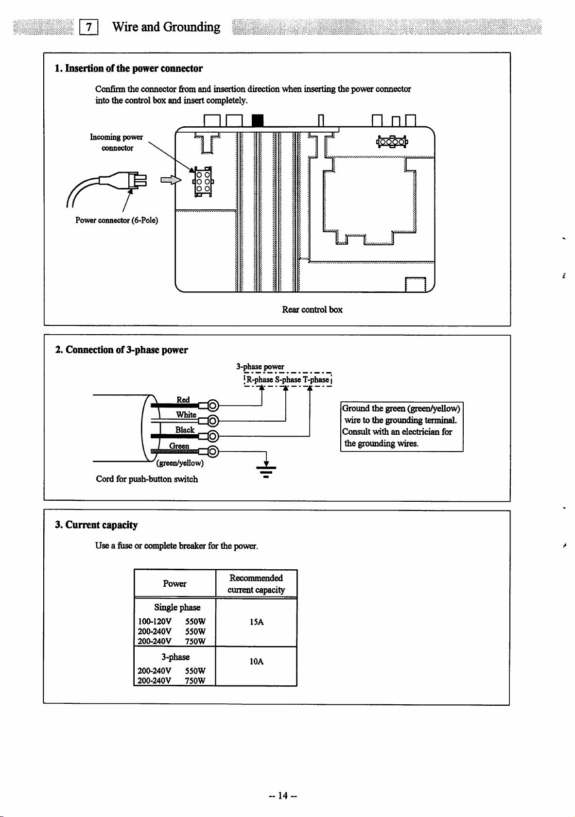
1. Insertion of
the
power
connector
Confinn the connector from and insertion directionwhen inserting the power connector
into the control box and insert completely.
Incomingpower
connector
%
Power connector (6-Pole)
2. Connection of 3-phase power
kr
O O
o o
o o
3-phase power
I
R-phase
S-phase
Rear
JL
control
T-phase
box
j
n
nn
3.
Current
White
Black
Green
'(green/yellow)
Cord for push-button switch
capacity
Usea fuse or completebreakerforthe power.
Power
Single phase
100-120V
200-240V
200-240V
3-phase
200-240V
200-240V
550W
550W
750W
55bW
750W
Recommended
current capacity
15A
lOA
Ground the green (green^ellow)
wire to the grounding terminal.
Consult
withanelectrician
for
the grounding wires.
--14
-
Page 17
7.Wire
and
Groundin
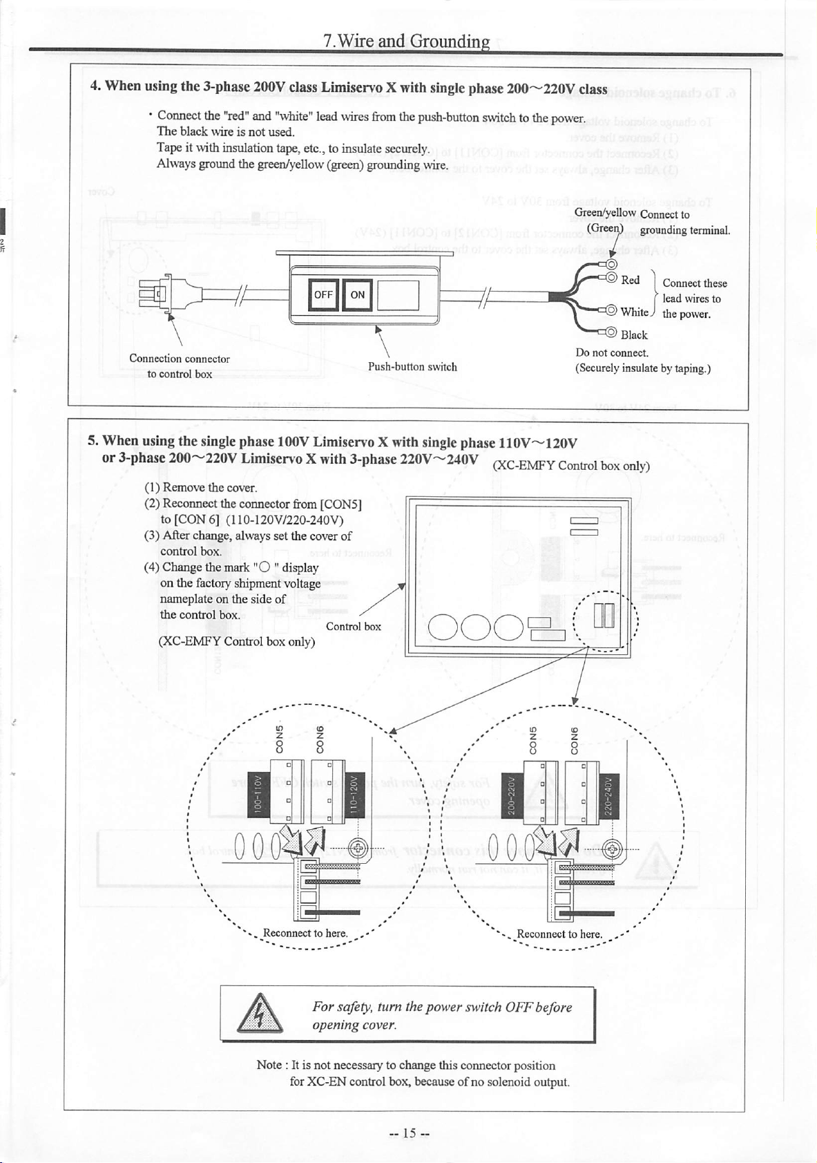
4.When usingthe3-phase
*
Connect
The
Tapeitwith
Alwaysgroundthe green/yellow (green)groundingwire.
black
the
"red"
wireisnot
insulation
200V
classLimiservo Xwith
and
"white"
lead
wires
used.
tape,
etc.,to
insulate
from
securely.
single
the
push-button
phase200'^220Vclass
switch
tothe
power.
Green/yellow Connect to
(GreeiO
*-©
Do
not
(Securelyinsulate by taping.)
grounding
Red1Connect
j
lead
Whitejthe
Black
connect.
terminal.
these
wires
to
power.
Page 18
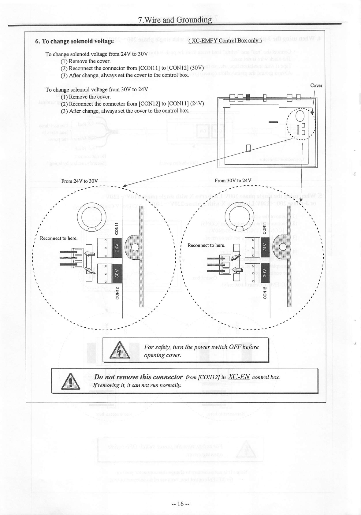
6. To change solenoid voltage
To change solenoid voltage from 24V to 30V
(1) Remove the cover.
(2)Reconnecttheconnector
(3)After change,alwayssetthe coverto thecontrolbox.
To change solenoid voltagefrom 30V to 24V
(1) Remove the cover.
(2)
Reconnect
the
connector
(3)After change,alwayssetthecoverto thecontrolbox.
7.Wire
from
[CONl1] to [CONl2](30V)
from
[CONl2]to [CONl1](24V)
and
Groundin
From
Reconnecttohere.
24Vto30V
^ t
. I
Reconnecttohere.
For
safety, turn thepower switch
opening
cover.
From30Vto24V
OFF
before
Do
not
remove
If
removing it, it can
this
connector
not
run normally.
from
[CONl
2]in
control
box.
Page 19
liiiii
H
Confirmation
1. Before turningswitches on...
Placestoconfirm
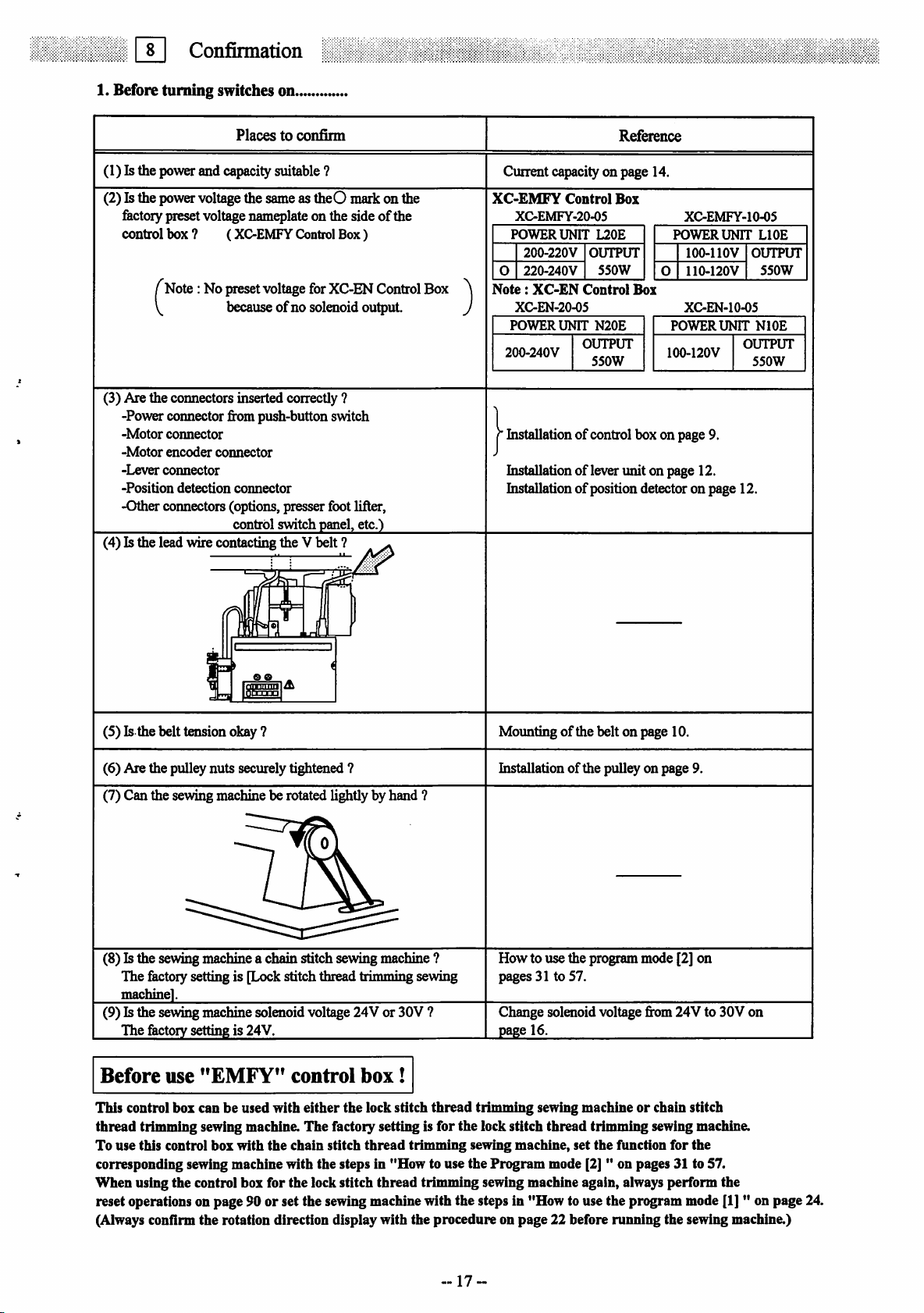
(1) Is the power and capacity suitable ?
(2)Isthe
power
voltage
thesameas theO markonthe
fectorypresetvoltage nameplateon the sideofthe
control box ? (XC-EMFY Control
f
Note:No
preset
voltage
for
XC-EN
Box)
becauseofno solenoid output.
(3) Are the connectors inserted correctly ?
-Power connector from push-button switch
-Motor
connector
-Motor
-Lever
-Position
encoder
connector
detection
connector
connector
-Other connectors (options, presser foot lifter,
control
switchpanel,etc.)
(4) Is the lead wire contacting the V belt ?
Control
Box
Reference
Current capacityon page 14.
XC-EMFY
XC-EMFY-20-05
POWER
0
Note:
XC-EN-20-05
POWER
200-240V
200-220V
220-240V
XC-EN
Control
UNIT
UNIT
L20E
OUTPUT
550W
Control
N20E
OUTPUT
550W
Box
Box
XC-EMFY-10-05
POWER
lOO-llOV
0
110-120V
XC-EN-10-05
POWER
100-120V
histallation of control box on page 9.
histallation of lever unit on page 12.
Installation of position detector on page 12.
UNIT
UNIT
LIOE
OUTPUT
550W
NlOE
OUTPUT
550W
(5) Is the belt tension okay ?
(6) Are the pulley nuts securely tightened 7
Mounting of the belt on page 10.
Installation of the pulley on page 9.
(7) Can the sewing machine be rotated lightly by hand ?
(8) Is the sewing machine a chain stitch sewing machine ?
The factory setting is [Lock stitch thread trimming sewing
How to use the program mode [2] on
pages 31 to 57.
machine].
(9) Is the sewing machine solenoid voltage 24V or 30V ?
The
factory
settingis 24V.
Before
This control box can be used with
thread
To use this control box with
use
"EMFY"
control
either
box!
the lock stitch
thread
trimming sewing machine. The factory settingis for the lock stitch thread trimming sewing machine.
the
chain stitch
thread
trimming
corresponding sewing machine with the steps in "How to use the Program mode [2] " on pages 31 to 57.
When using the control box for the lock stitch thread trimming sewing machine again, always perform the
Change solenoid voltage from 24V to 30V on
page16.
trimming sewing machineorchain stitch
sewing machine, set
the
function
for
the
reset operations on page 90 or set the sewing machine with the steps in "How to use the program mode [1] " on page 24.
(Always confirm
the
rotation direction displaywith the
procedureonpage
22 before
running
the sewing machine.)
17
Page 20
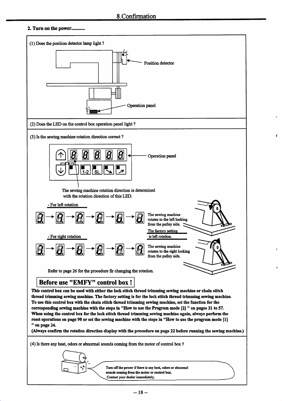
2.
Turnonthe
(1) Does the position detector lamp light ?
power.
S.Confirmation
4
U
Operation panel
(2) Does the LED on the control box operation panel light ?
(3) Is the sewing machine rotation direction correct ?
01
The sewing machine rotation direction is determined
with
i i i i
the
rotation
directionofthis
LED.
Position
detector
Operation panel
-
For
left
rotation
The sewing machine
rotates to the left looking
fromthe pulleyside.
^^fector^ettin^
is
left
For
right
rotation
Refer to page 26 for the procedure fir changing the rotation.
Before
This control box can be used with either the lock stitch
thread
To use this control box with
corresponding sewing machine with the steps in
When
using the control box for the lock stitch
reset operations on
" on
page
(Always confirm the rotation direction displaywith the procedure on page 22 before running the sewing machine.)
use
"EMFY"
trimming sewing machine.
the
page90or
24.
set
control
The
factory settingis for the lock stitch
chain stitch
the
sewing machine with
box
thread
"How
thread
!
thread
trimming
to use
trimming sewing machine again, always perform the
the
rotation.
The sewing machine
rotates to the right looking
ftom the pulley side.
trimming sewing machineorchain stitch
thread
trimming sewing machine.
sewing machine,
the
Program
steps in
set
the
function for
mode [2] " on pages 31 to 57.
"How
to use
the
pn^ram
the
mode [1]
(4) Is there any heat, odors or abnormal sounds coming fi'omthe motor of control box ?
Turnoffthe power ifthere is any heat, odors or abnormal
soundscomingfromthe motor or control box.
Contact your dealer immediately.
18-
Page 21
Q
Adjustments
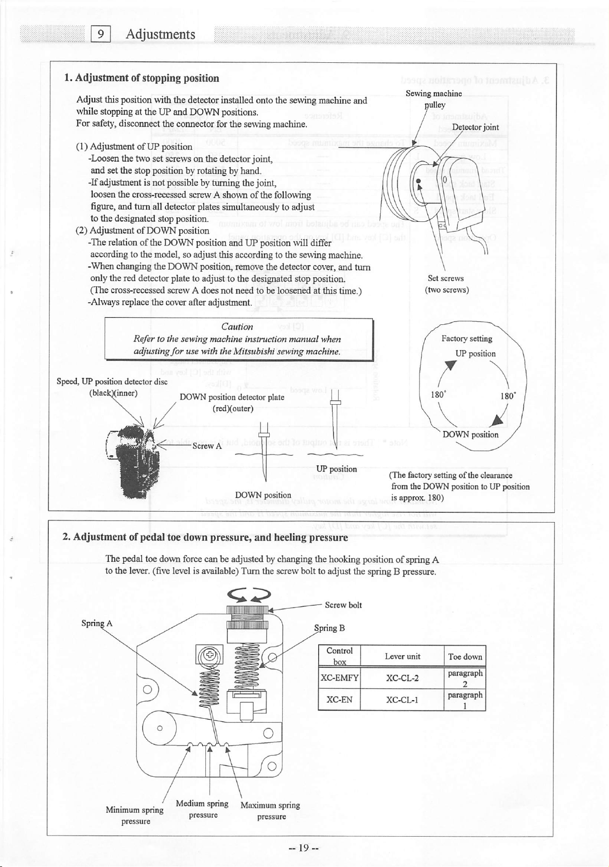
1. Adjustment of stopping position
Adjust this positionwiththe detectorinstalledontothe sewingmachineand
^\1lile
stopping at the UPand DOWNpositions.
For safety,disconnect the connector forthe sewing machine.
(1) AdjustmentofUP position
-Loosen the two set screws on the detector joint,
and set the stop position by rotating by hand.
-Ifadjustmentis notpossiblebyturningthejoint,
loosen the cross-recessed screw A shown of the following
figure,andturn alldetectorplatessimultaneously toadjust
to the designated stop position.
(2) Adjustment of DOWN position
-Therelationofthe DOWNpositionand UP position\villdiffer
according to the model, so adjust this according to the sewing machine.
-When changing the DOWN position, remove the detector cover, and turn
only the red detector plate to adjust to the designated stop position.
(The cross-recessed screwAdoesnot need to be loosenedat this time.)
-Alwaysreplace the cover afteradjustment.
Caution
Refer to the sewingmachine instruction
adjusting
for
use with the Mitsubishi sewing machine.
manual
when
Sewing machine
pulley
Detectorjoint
Set
screws
(two
screws)
Factory setting
UP position
Speed, UP position detector disc
(blackQ^ner)
DOWN
/
•
Screw
position
detector
(redXouter)
A
DOWN position
plate
UP position
DOWN position
(The &ctory setting of the clearance
from the DOWNposition to UP position
isapprox. 180)
Page 22
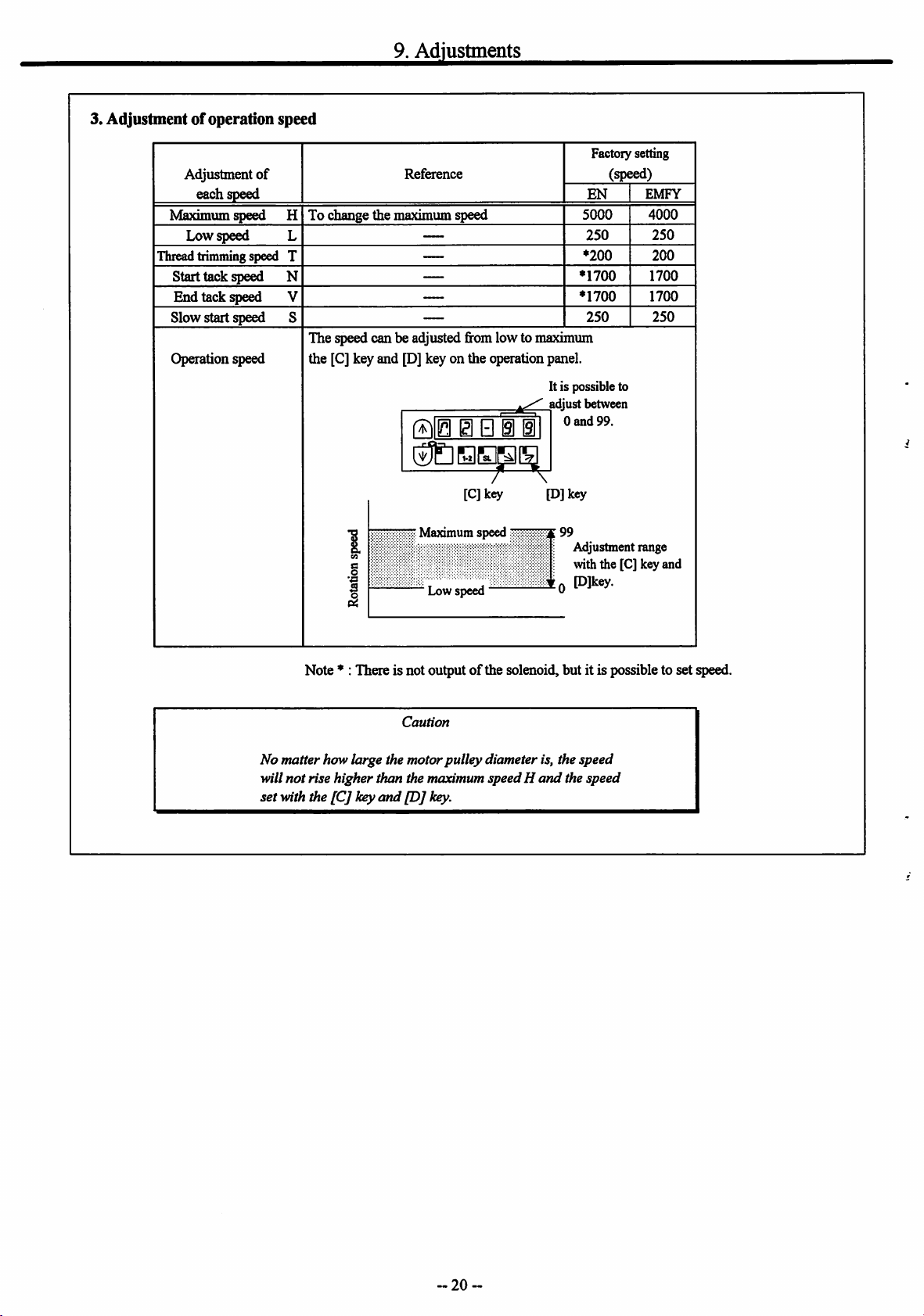
3. Adjustment of operation speed
Adjustment
each
Maximum speed H
Low speed
Thread trimming speed T
Start tack speed N
End tack speed V
Slow start speed 8
Operation speed
of
speed
9.
Adjustments
Reference
To change the maximum speed
The speed can be adjusted fromlow to maximum
the [C] key and [D] key on the operation panel.
It is possible to
adjust between
0
ffllEI gl B i i
and
liULlElBSCS
7^^
[Cjkey
[D] key
Factory setting
(speed)
EN
5000
250
♦200
'1700
♦1700
250
99.
EMFY
4000
250
200
1700
1700
250
:f99
Adjustment range
with the [C] key and
0
Plkey.
1
Maximumspeed
§
Lowspeed
Note♦: There is not outputofthe solenoid, but it is possible to set speed.
Caution
No matter how large the motorpulleydiameter is, the speed
will
not
rise higher than the maximum speedH
set with the
[C]
key
and
[D]
key.
and
the
speed
20
Page 23
[Tol
Pedal
Operation
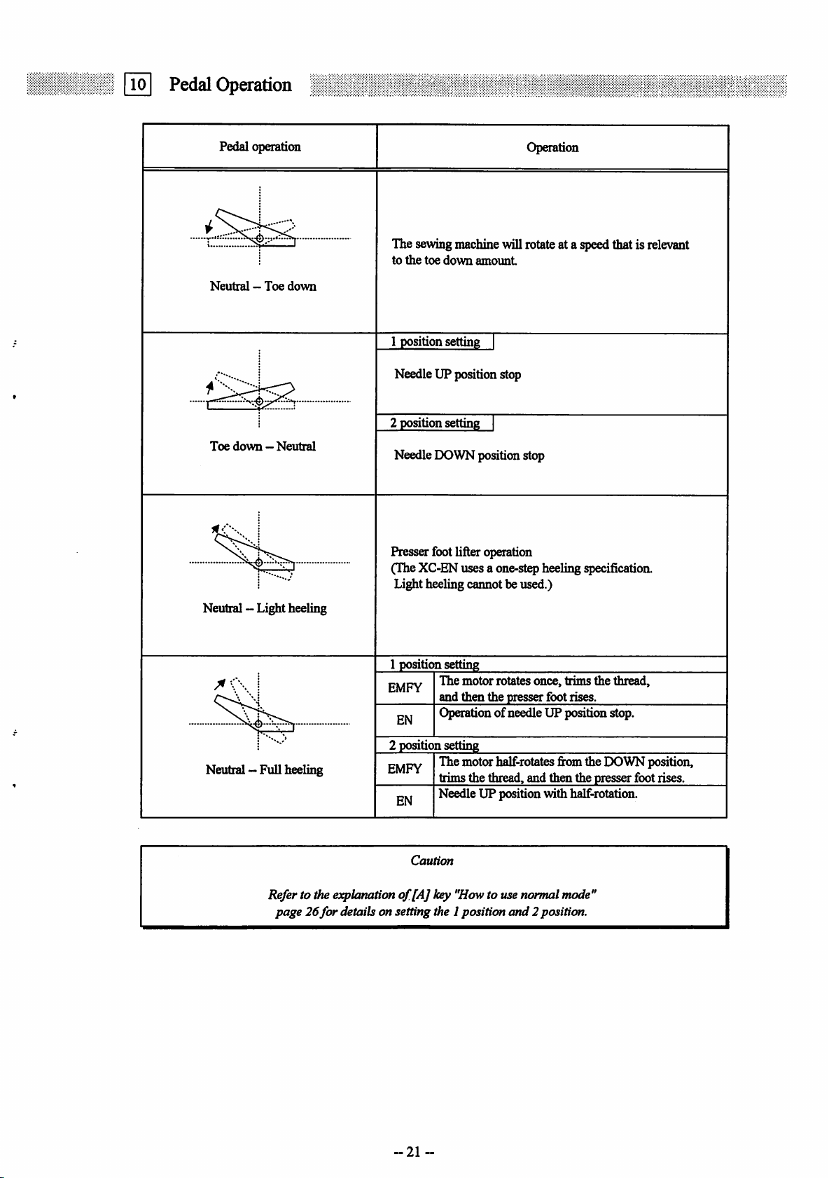
Pedal operation
Neutral—Toe
Toe
down-Neutral
down
Operation
The sewingmachinewill rotateat a speedthat isrelevant
to
the
toe
down
amount
1 position setting
NeedleUP positionstop
2
position
setting
Needle DOWN position stop
Presser footlifter operation
(The XC-ENuses a one-stepheeling specification.
Light heeling caimot be used.)
Neutral —Light heeling
Neutral —Fullheeling
Refer to the explanationof[A] key "Howto usenormal mode"
page26for
1 positionsetting
The
EMFY
EN
2 position setting
EMFY
EN
Caution
motor
andthenthe presserfootrises.
Operation of needle UP positicmstop.
The motor half-rotates
trims
the
thread,
Needle UP position with half-rotaticm.
details on setting the 1position
rotates
and
once,
fix>m
and
then
2position.
trims
the
thread,
the DOWN position,
the
presser
foot rises.
21
Page 24
[u]
Operationofthe
Operation
Panel
Keys
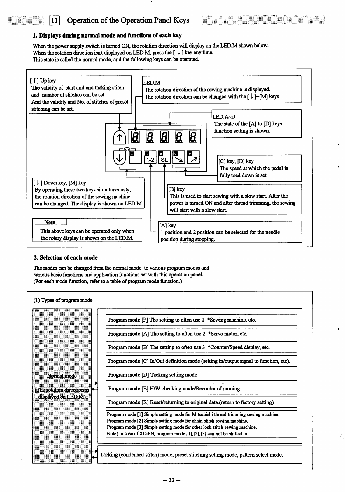
1. Displays during normal mode
When
the
power
supply
switchisturned
When
the
rotation
This state is called the normal mode, and the following keys can be operated.
direction
isnt
[T]Upkey
The validityofstart and end tacking stitch
and
numberofstitches
And the validityand No.ofstitches of preset
stitching can be
canbeset.
set
and
fimctions of each key
ON,
the
rotation
displayedonLED.M,
LED.M
The rotation direction of the sewing machine is displayed.
The
direction
press
rotation
will
the[ i ]
direction
display
key
miBi a a a B
r—
0
[I ]
Down
key,
[M]
key
By operating these two keys simultaneously,
the rotation direction
can
be changed.
of
the sewing machine
The
display is shownon LED.M.
Q
1-2
[B]key
This is used to start sewing with a slow start. After the
power is turned ON and after thread trimming, the sewing
will
start
onthe
any
time.
canbe
changed
withaslow
LED.M
LED.A~D
The stateofthe [A] to [D] keys
function setting is shown.
[C] key, [D] key
The speedat which the pedal is
fiillytoed down is set.
start.
with
shown
the[ i
below.
]+[M]
keys
Note
This above keys can be operated only when
the rotary display is shown on the LED.M.
2.
Selectionofeach
The modes can be changed from the normal mode to various program modes and
various basic functions and application functions set with this operation panel.
(For each mode function, refer to a table of program mode function.)
(1) Typesofprogram mode
Normal
(The rotation direction is
mode
dl^layed on
mode
Program mode [P] The setting to often use 1 *Sewing machine,etc.
Program mode [A] The setting to often use 2 *Servo motor, etc.
Program mode [B] The setting to often use 3 •Counter/Speed display, etc.
Program mode [C] In/Out definition mode (setting in/output signal to function, etc).
Program mode [D] Tacking setting mode
Program mode [E] H/W checking
LEDJM)
Program mode [R] Reset/returning to original data.(retum to factory setting)
[A] key
1 position and 2 positioncan be selected forthe needle
positionduring
stopping.
mode^ecorderofrunning.
Program mode [1] Simple setting mode for Mitsubishi thread trimming sewing machine.
Program mode [2] Simplesetting mode forchain stitch sewing machine.
Program mode [3] Simple setting mode for other lock stitch sewing machine.
Note) In caseof XC-EN,programmode[1],[2],[3]can not be shifted to.
Tacking (condensed stitch) mode, preset stitching setting mode, pattern select mode.
22
Page 25
11.Operationofthe Operation Panel Keys
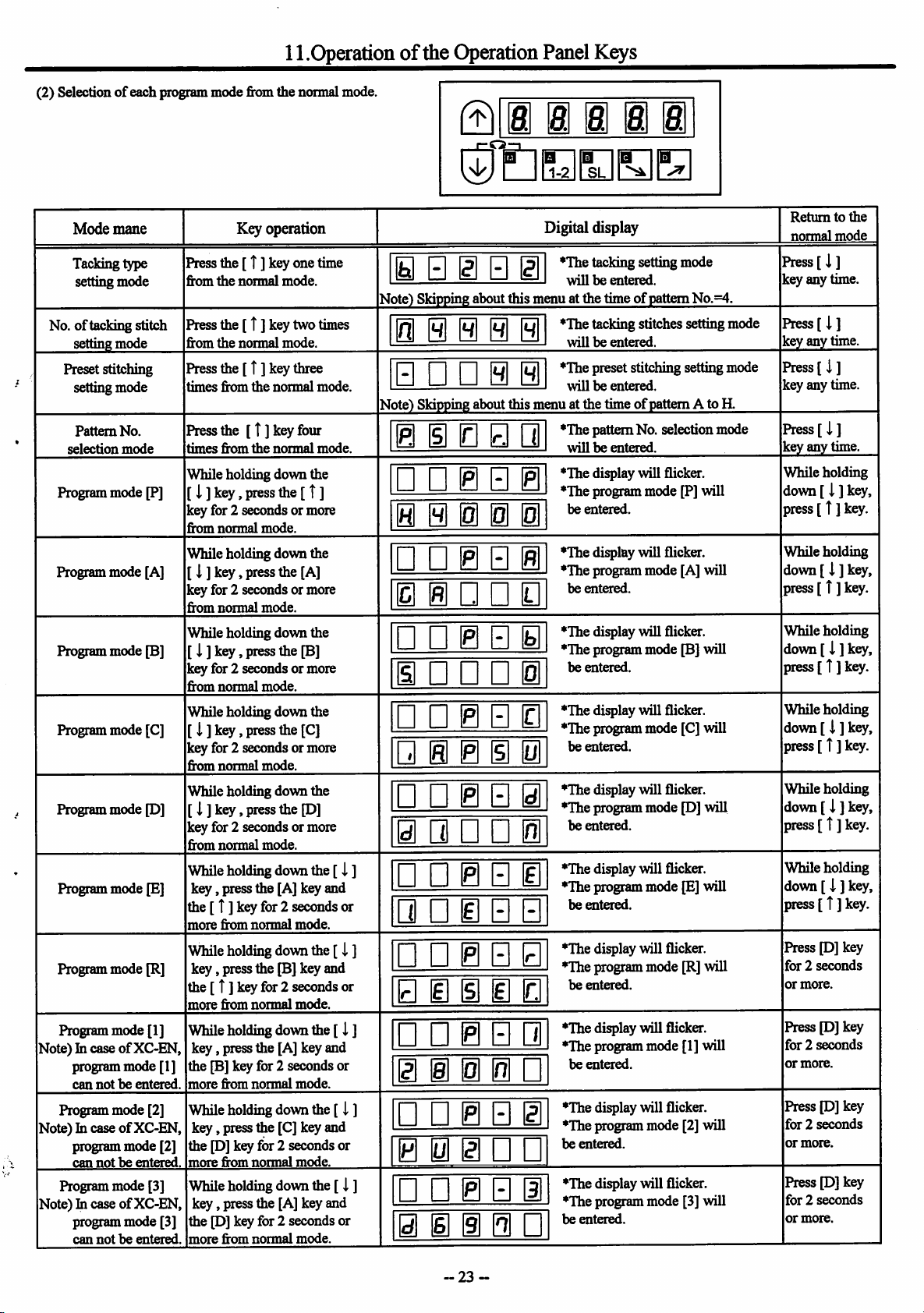
(2) Selectionofeach program mode from the normal mode.
©
8. 8 8 8
i
B
1-2
mSLB a
Mode
mane
Tacking type
setting mode
No.oftacking stitch
setting
mode
Preset stitching
setting mode
Pattern
No.
selection
Program mode [P]
Program mode [A]
Programmode [B]
Program mode [C]
Programmode [D]
Program mode [E]
Program mode [R]
Program mode [1]
Note) In case
programmode [1]
can
Programmode [2]
Note) In caseofXC-EN,
program mode [2]
cannot be
Program mode [3]
Note) In caseofXC-EN,
program mode [3]
can
mode
of
XC-EN,
notheentered.
entei^.
notbeentered.
Keyoperation
Pressthe[ t ]keyone
from
the
normal
Press
the[T] keytwo
from
the
normal
Press
the[ t ] key
times
from
the
Press
the
[t]keyfour
times
from
the
While holding down the
[ i ]key,
key for 2 seconds or more
from
While holding down the
[ i ] key,
key for 2 seconds or more
from
While holding down the
[ i ] key,
key for 2 seconds or more
from
While holdingdown the
[ I ] key,
key for 2 seconds or more
from
While holding down the
[ i ]key,
key for 2 seconds or more
from
While
key,
the[ t ]
more
While
key,
press
normal
mode.
press
normal
mode.
press
normal
mode.
press
normal
mode.
press
normal
mode.
holding
press the [A] key and
key
for2
from
normal
holding
pressthe [B] key and
the[ T] keyfor2
more
from
normal
While
holding
key,
pressthe [A] key and
mode.
mode.
three
normal
normal
the[ t ]
the
[A]
the
[B]
the
[C]
the
[D]
down
seconds
mode.
down
seconds
mode.
down
time
times
mode.
mode.
the[ i ]
the[i ]
the[ i ]
the [B]key for 2 secondsor
more
from
normal
mode.
While
holding
key,
press the [C] key and
down
the[ i ]
thep]keyfor 2 seconds or
more
from
normal
mode.
While
holding
key,
press the [A] key and
p]
the
more
from
down
the[J.]
keyfor 2 seconds or
normal
mode.
or
or
0 S g S gl
N
ote)
N
10
•
ote)
Skipping
Skipping
about
0 0 0
••00
about
0 0 0 • •
• • 0 E 0
0 0 0 0 1
•
•0Si
0 i • • D
• • 0 E 0
0 • E • 1
• • 0 E 0
•
0000
• • 0 E 0
0 • • • 1
• • 0 E 0
•
•0EE
•
•0EB
E 0 0 0 0
• • 0 E 0
0 i
11
• • 0 E 0
0 0 0 • •
• • 0 E 0
0 0 0 0 •
Digital display
jnuatthe
this
m(
muatthe
this
m(
•
*Thetacking setting mode
willbeentered,
timeofpattern
*Thetacking stitches setting mode
willbeentered.
*Thepreset stitching setting mode
willbeentered,
timeofpattern
♦The
pattern No. selection mode
willbeentered.
♦The
display will flicker.
♦The
program mode [P] will
be
entered.
♦The
display will flicker.
♦The
program mode [A] will
be
entered.
♦The
display will flicker.
♦The
program modeP]will
be
entered.
♦The
display will flicker.
♦The
programmode [C] will
be
entered.
♦The
display will flicker.
♦The
program modep]will
be
entered.
♦The
display will flicker.
♦The
programmodep]will
be
entered.
♦The
display will flicker.
♦The
programmode[R] will
be
entered.
♦The
display will flicker.
♦The
programmode[I] will
be
entered.
♦The
display will flicker.
♦The
programmode [2] will
be
entered.
♦The
display will flicker.
♦The
programmode [3] will
be
entered.
No.=4.
A to H.
Returntothe
normal
mode
Press[J,
key any time.
]
Press[ i ]
key
any
time.
Press[
i]
key any time.
Press[i]
key
any
time.
While holding
down
[ i ]
key,
press
[ T]
key.
While holding
down[ i ] key,
press[ T]
While holding
down
press[ T]
Whileholding
down
press
While holding
down[ \ ]
press
Whileholding
down[i ]
press
Pressp]key
for2seconds
or
Pressp]key
for2seconds
or
PressP]key
for2seconds
or
PressP]key
for2seconds
or
more.
more.
more.
more.
[ i ]
[ i ]
[ t ]
[ T]
[ T]
key.
key,
key.
key,
key.
key,
key.
key,
key.
-23
Page 26
11.Operationofthe Operation Panel Keys
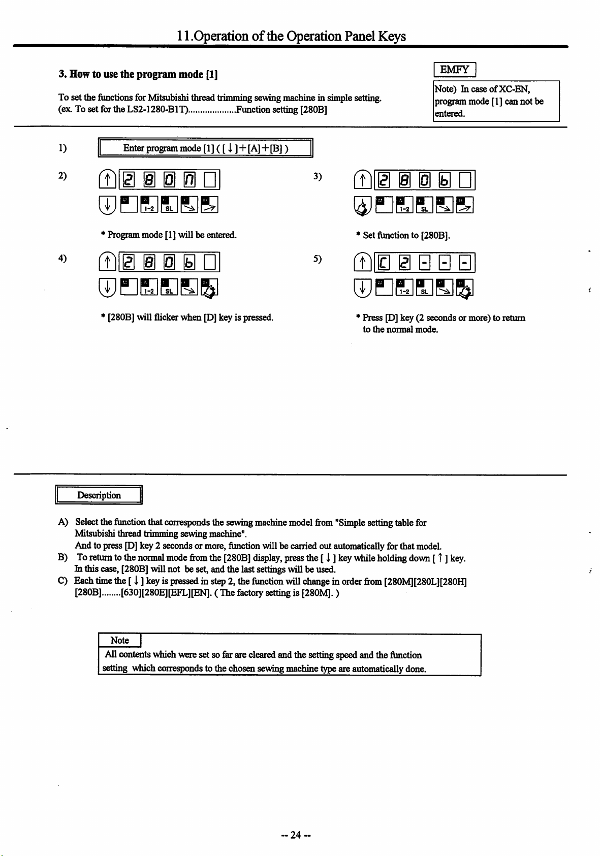
3. How to use the
Toset the functions forMitsubishithreadtrimmingsewingmachinein simplesetting,
(ex.To setfortheLS2-1280-BIT) Functionsetting[280B]
1)
2)
4)
ftllB i i
* Program mode [1] will be entered.
fB
program
Enter
program
i 0 •
mode [1]
mode
[1]([i ]+ [A]+[B])
ED
fBig i i 0 •
♦
Set function to [280B].
[Bib 0 • • 0
©EBEE^
♦
[280B] will flicker
wdien
[D]key is pressed.
* Press [D] key (2 seconds or more) to return
to
the
normal
EMFY
Note) hi caseofXC-EN,
program mode [1] can not be
entered.
mode.
Description
A) Selectthe function thatcorresponds the sewing
Mitsubishithread trimming sewingmachine".
And topress[D]key2 secondsormore,functionwillbecarriedout automatically forthatmodel.
B)
To
return
tothe
normal
mode
from
the
[280B]
In
this
case,
[280B]
will
notbeset,
C)
Each
time
the
[i ]
keyispressedinstep2,the
[280B] [630][280E][EFL][EN]. ( The factorysettingis [280M]. )
Note
Allcontentswhichweresetsofarareclearedand the settingspeedand thefunction
setting
which
corresponds
and
to thechosen
the
machine
display,
last
settings
function
sewing
modelfrom
press
the[I ]
willbeu^.
will
changeinorder
machine
"Simple
key
typeare
settingtablefor
Mhile
holding
from
[280M][280L][280H]
automatically
down
done.
[t ]
key.
24
~
Page 27
♦5
Function
name
280M
280H
280B
210M
230M
230L
^
230B
2S0M
2S0A
2S0B
3370
359
3310
3750
410B
430B
4710
4730
630
280E
EFL
EN
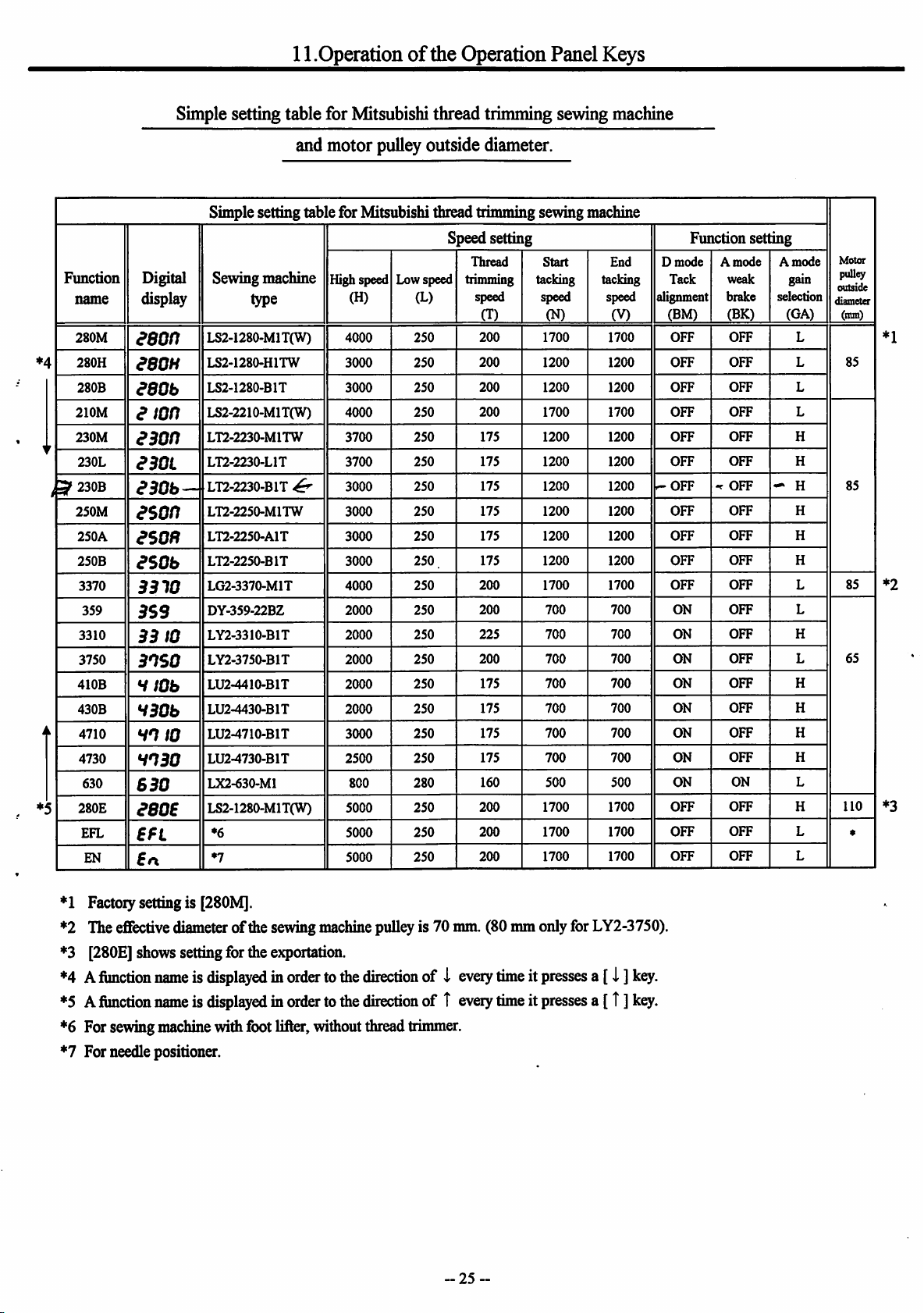
11.Operationofthe Operation Panel Keys
Simplesetting table for Mitsubishithread trimming sewingmachine
and motor pulleyoutside diameter.
Simplesetting table for Mitsubishi thread trimming sewingmachine
peedsetting Function setting
s
Digital
display
aeon
eeoH
asob
a
ton
aaon
asoL
ason
ason
asob
B310
BSS
BB
Bnso
HtOb
HBOb
HO
HOBO
6B0
aeoe
£n
£n
Sewingmachine
LS2-1280-M1T(W)
LS2-1280-H1TW
LS2-1280.B1T
LS2-2210-M1T(W)
LT2-2230-M1TW
LT2-2230-L1T
LT2-2230-B1T
LT2-2250-M1TW
LT2-2250-A1T
LT2-2250-B1T
LG2-3370-M1T
DY-359-22BZ
LY2-3310-B1T
to
LY2-3750-B1T
LU2-4410-B1T
LU2-4430-B1T
LU2^710-B1T
to
LU2-4730-B1T
LX2-630-M1
LS2-1280-M1T(W)
•6
•7
type
^
High speed
(H)
4000
3000
3000
4000
3700
3700
3000
3000
3000
3000
4000
2000
2000
2000
2000
2000
3000
2500
800
5000
5000
5000
Lowspeed
(L)
250
250
250 200
250 200
250
250
250
250
250
250
250
250
250
250
250
250
250
250
280
250
250
250
Thread
trimming
speed
(T)
200
200
175
175
175
175
175
175
200
200
225
200
175
175
175
175
160
200
200
200
Start
tacking
speed
(N)
1700
1200
1200
1700
1200
1200
1200
1200
1200
1200
1700
700
700
700
700
700
700
700
500 500
1700
1700
1700
End
tacking
speed
(V)
1700
1200
1200
1700
1200
1200
1200
1200
1200
1200
1700
700
700
700
700
700
700
700
1700
1700
1700
D
mode
Tack
alignment
(BM)
OFF
OFF
OFF
OFF
OFF
OFF
^OFF
OFF
OFF
OFF
OFF
ON
ON
ON
ON
ON
ON
ON
ON
OFF
OFF
OFF
•r
A
brake
mode
weak
(BK)
OFF
OFF
OFF
OFF
OFF
OFF
Off
OFF
OFF
OFF
OFF
OFF
OFF
OFF
OFF
OFF
OFF
OFF
ON
OFF
OFF
OFF
A
mode
gain
selection
(GA)
L
L
L
L
H
H
H
H
H
H
L
L
H
L
H
H
H
H
L
H
L
L
Motor
puU^
outside
diameter
(mm)
85
85
85
65
110
*
*1
*2
*3
*1 Factoiy setting is [280M].
*2 Theeffective diameterofthesewing
machine
pulleyis 70mm. (80mm onlyforLY2-3750).
"'3 [280E]showssettingfortheexportation.
'''4Afunction
*5Afunction
*6 For sewing
nameisdisplayedinordertothe
nameisdisplayedinordertothe
machine
withfootlifter, widiout thread
direction
direction
trimmer.
of i
of T
eveiy
timeitpresses
every
timeitpresses
a[i ]
a [T]
key.
key.
*7 For needlepositioner.
25
Page 28
11.Operationofthe Operation Panel Keys
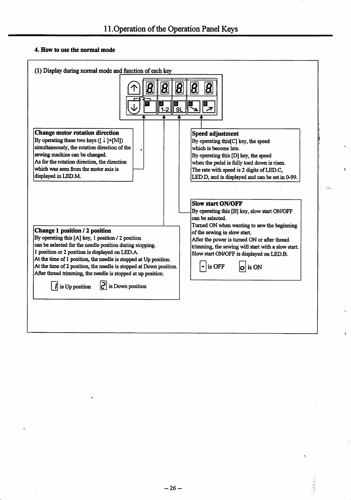
4.
Howtouse
(1) Display during normal mode and functionofeach key
the
normal
mode
la|
e. a a
j*"!
Change motorrotation direction
By
operating
simultaneously,the rotation directionofthe
sewingmachinecan be changed.
As for the rotation direction, the direction
which
displayed in
Change
By operatingthis [A] key, 1 position / 2 position
can be selectedfor the needle positionduring stopping.
1 position or 2 position is displayedon LED.A.
At the timeof 1position,theneedleis stoppedat Up position.
At thetimeof 2 position,the needle is stoppedatDownposition.
Afterthreadtrimming, the needleis stopped at upposition.
these
two
keys
was
seen
from
the
motor
LED.M
1 position / 2 position
([i
]+[M])
axis
is
|Q3|
•
B B
SL
Speed
adjustment
By operatingthis[C] key, the speed
whichisbecome
By operatingthis [D] key, the speed
when the pedal is fully toed down is risen.
The rate with speed is 2 digits ofLED.C,
LED.D, and is displayed and can be set in 0-99.
Slow
start
By operating this [B] key, slow start ON/OFF
canbeselected.
Tumed ON when wantingto sew the beginning
of
the sewing in slow start.
After the power is tumed ON or after thread
trimming, the sewing will start with a slow start.
Slow start ON/OFF is displayed on LED.B.
-is
0
ON/OFF
OFF
late.
is
ON
[7|isUp
position0is
Down
position
-
26
Page 29
11.Operationofthe Operation Panel Keys
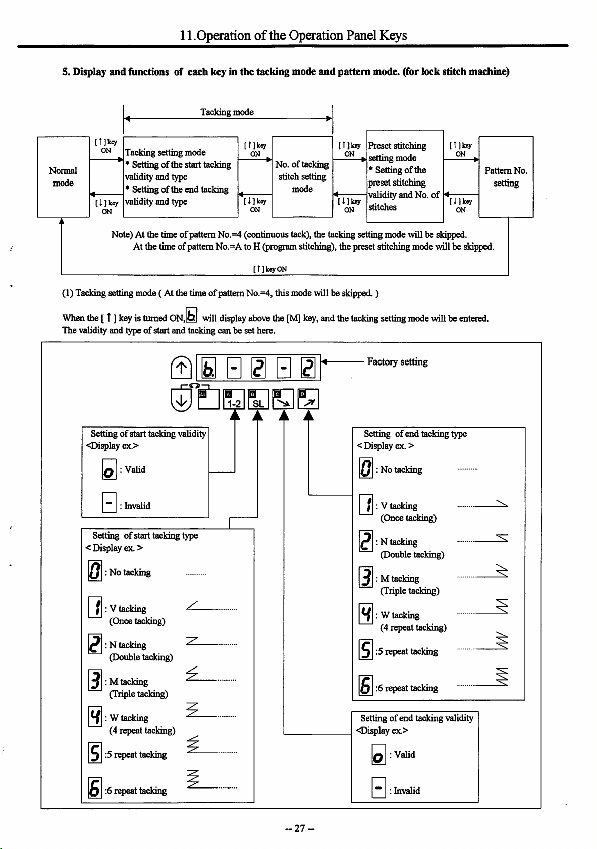
5. Display
Normal
mode
(1) Tackingsettingmode( At the time ofpatternNo.=4, this mode will be skipped.)
When
The validity and typeofstart and tacking can be set here.
and
functions of each key in
Tacking mode
Tacking setting mode
* Settingofthe start tacking
validity and type
* Setting of the end tacking
validity and type
Note) At the timeofpattern No.=4 (continuous tack), the tacking setting mode will be skipped.
At the time ofpattern No.=A to H (programstitching), the preset stitching modewill be skipped.
the
[T]
keyisturned
ON.I^
will
the
[T]keyON
display
above
tacking mode
No. of tacking
stitch setting
mode
the
[M]
key,
and
and
pattern
the
mode, (for lock stitch machine)
Preset stitching
setting mode
* Setting
preset stitching
validity and No. of
stitches
tacking
setting
Factory setting
of
the
mode
[T]key
ON
willbeentered.
Pattern
setting
No.
[3^
Settingofstart tacking validity
<Di^lay
< Display ex. >
0
[~^:Vtacking
ex.>
VaUd
0:
Invalid
0:
Setting of start tacking type
:No tacking
(Once tacking)
:N tacking
(Double tacking)
: M tacking
(Triple tacking)
B
B
SL
^ A A A
Setting of end tacking type
< Display ex. >
: No tacking
0
|~^:Vtacking
(Once tacking)
:N tacking
(Double tacking)
: M tacking
(Triple tacking)
: W tacking
(4 repeat tacking)
:Srepeat tacking
:6 repeat tacking
: W tacking
(4 repeat tacking)
:5 repeat tacking
:6 repeat tacking
27
Setting
of
end tacking validity
<Display ex.>
Valid
0
Invahd
0
Page 30
11.Operationofthe Operation Panel Keys
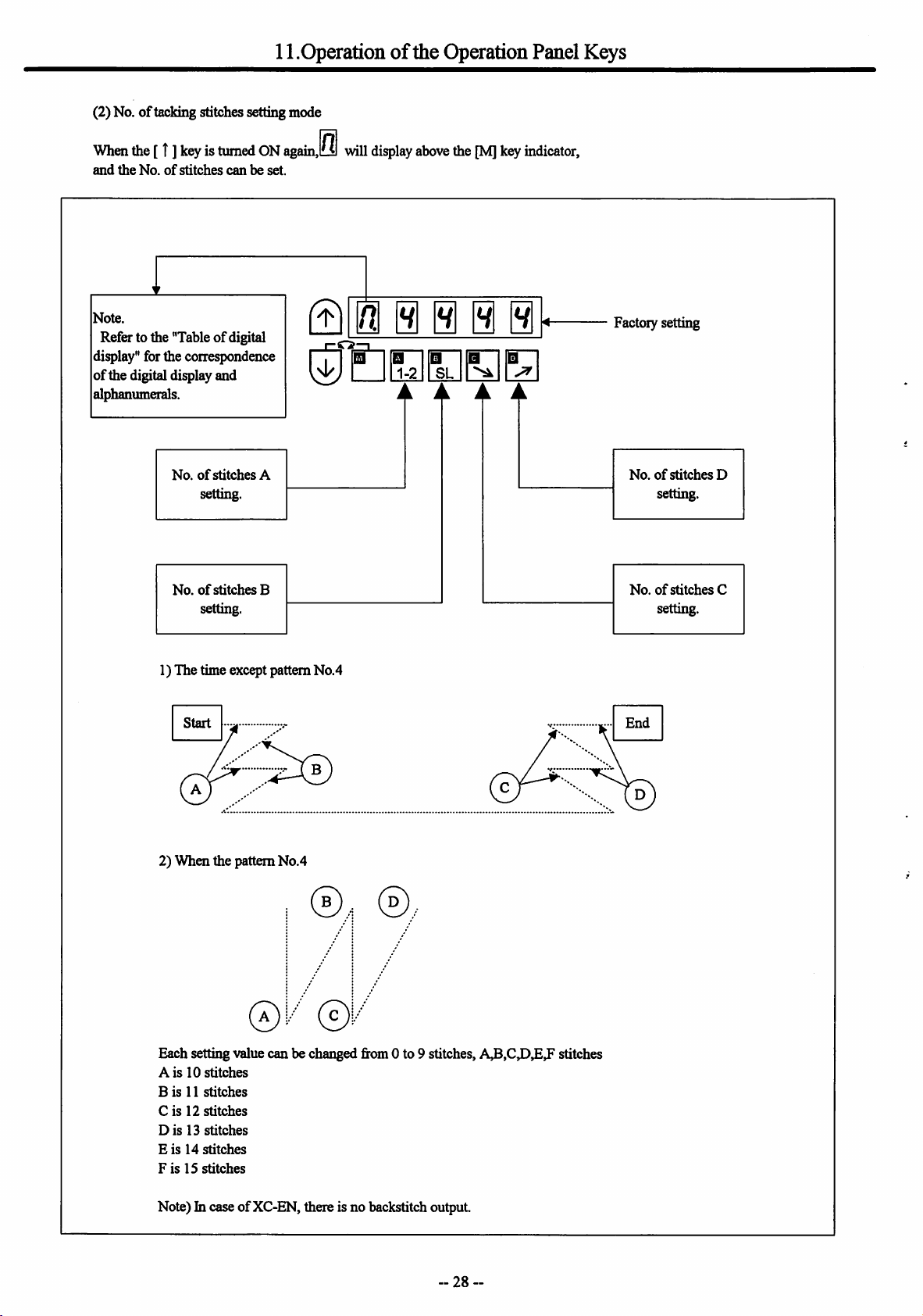
(2) No.oftacking stitches setting mode
When
the
[t]
and
the
No.ofstitches
keyisturned
ON
canbeset.
again,l0l
will
display
above
the
[M]
key
indicator,
Note.
Refer to the "Tableofdigital
display"forthecorrespondence
of
the digital display and
alphanumerals.
No.ofstitches
settmg.
No.ofstitches
settmg
1) The time except pattern No.4
Start
A
B
© i @@@s
B
m
1-2
©
SL
A A A
Factory setting
No.ofstitches
settmg.
No.ofstitches
settmg.
End
D
C
2)
When
the pattern
Each setting value can be changed from 0 to 9 stitches, stitches
Ais10
stitches
Bis11
stitches
Cis12
stitches
Dis13stitches
Eis14
stitches
FisIS
stitches
Note) In case ofXC-EN, there is no backstitch output.
No.4
©,.i
®.
~
28
Page 31

11.Operationofthe Operation Panel Keys
(3) Preset stitching settingmode
1) When the pattern is the time except patternNo.4
Q • • • 0 B
Factory setting
of
0:
0:
preset stitching
VaUd
hivalid
Setting
<Display ex.>
Start tacking
0
End
tacking
2) When the pattern is No.4
|
Start
tacking
that
was
N
End
tacking
thatwasinthe
QEnnnir
1-2MSLN>^I
inthe
an
tacking
tacking
H I
mode
mode
will
will
Setting of No. stitches N
( 0 to 9999 stitches )
start
start
atthe (D
atthe d)
position.
positioiL
-Factory setting
Settingofcontmuons
tack stitching validity
Oisplay
0:
®4
0""
©'"
ex.>
Valid
hivalid
N
@/
In the No. of times(N) setting is N=3, the stitching will be
in the order or
will be in the orderofA3.C3.C.If
orderwill be
(IfN=0, tackingwill continue in the order ABCDCD... while
the pedal is pressed down.)
Note) hi case of XC-EN, there is no backstitch output.
29-
A3
snd C. If the setting is N=5, the stitching
A,B,C3,C3
Setting of No. times N
(0 to 9999 stitches)
the N is 6 or more, the
Page 32

11.Operationofthe Operation Panel Keys
(4) Pattern No. selection mode
When
the[ t ] keyis
Selectingof preset stitching setting, continuous tack stitching, program stitching(pattern No. A to H).
1) Display of preset stitching (Pattern 0 to 3)
turnedONagain,
andthe
pattern
No.
selection
mode
willbe
entered.
Q 0 S 0 0 B
©•BaSB
2) Displayof continuous tack stitching (Pattern 4)
© 0 E i 0 S
1-2MSL
3) Displayofprogram stitching (Pattern A to H)
g)0@0Si
M^ M ^
w
Display of pattern 0.
When pattern 1,2,3, display show 1,2,3.
When control panel is connected,
the pattern 0 disappears.
Display of pattern A
When pattern B, C, D, E, F, G, H display
showB,C,D,E,F,G,H
a.Pattern A throughH can be set on controlpanel "XC-E500Y".
Sov4ien programming will be changed, use control panel "XC-E500Y".
(Referto technicalmanualof controlpanelin detail)
Caution
For
safetypurposes, always turn
whenconnectingor disconnecting the controlpanel.
off
thepowerswitch
-30
~
Page 33

Howto use SimplesettingofProgramMode [2] (for chain stitchtrimmingmachine)
1. How to use
the
program
No.1 Tosetthe functionsforchain stitchsewingmachinein simplesetting
(Ex.to set forthe VC2600class,
1)
2)
4)
mode [2]
"YAMATO")
Enter
program
mode
[2]
([ i ] +
i • • •
Program mode [2] will be entered.
[C]+[D])
Functionsetting
^dicates
3)
ftllB i B • •
5)
ftllB i a • PI
[^•EEB®
[YU2] will flickerwiien [D] is pressed.
6)
[YU2]
keyoperation.Referto Page23.)
CEEBB
Set function to [YU2].
D E B B
[CLEAR]will be displayedwhenthe [D] key is
pressed for approx. two seconds.
[T]ID
[Tj
PressP]to return to the normal mode.
Description
A)
Select
the
function
chainstitch
willbe
carried
B)To
return
tothe
hi thiscase, [YU2]willnot be set, and the lastsettingswillbe used.
C)
Each
time
the
[YU4] [JMH].
D)RefertoFig.1(page34)fortheconnectorinput/output signals.
E) RefertoFig.50
F) Setthesolenoidvoltage to 30V.Refertopage16.(The
G) Set the optionA
H) The thread trimmingprotectionsignal S6will stopthe sewingmachinewhen the switchis turned OFF.
i B
B~EI
BEEEB
that
corresponds
sewing
machine"
out
automatically
normal
[ i
]keyispressedinstep2,the
^age
cormector
onthe page32.
mode
from
50)forthejunction
5/12Vsettingto
tothe
forthat
the
sewing
Display
model.(Refer
[YU2]
display,
function
wiring.
12V.
Refertopage71.(The
machine
[CLEAR]
tothe
press
will
factory
model
for
"Simple
withtheP]key,and
simple
setting
the[ T]
key
while
changeinorder
settingis 24V.)
factory
setting
table
for
holding
from
[YU2], [YU3],
settingis 12V.)
table
for
fimctions
"YAMATO"onpage
down
[ 1].
32.)
31-
Page 34

(/>
§'
•o
Note
Note
Note
Sewing
Function
YU2
YU3
YU4
YU5
YCl
YC2
YC3
YC4
YVIO
lo
YVll
NOl
N02
machine
maker
YAMATO
YAMATO
YAMATO
YAMATO
YAMATO
YAMATO
YAMATO
YAMATO
YAMATO
YAMATO
PEGASUS
PEGASUS
Modelname of sewing machine and device
VC2600, VC2700
trimmer
VC2600, VC2700 class Air-operated under thread triinmer
with air wiper
VC384SP,2845P,2840PclassAir-operated under thread
trimmerwithairwq>er
Solenoid-operated under thread trimmerwithsolenoid wiper
CM3S7, CM400class for manual feed rollerdevice
condensed
CM400
stitch
invalid
CM3S7,
condensed
CM400
stitch
valid
VXseriesThe sewingmaehtnowiththe UT-A device
VXseriesThesewingmachinewith the UT-A/ST-Adevice Fig.3
W500,600,700
threadtrimmerwithsolenoidwqier withouttop coverthread
trimmer
WSOO,
thread trimmerwith solenoid wq>erandtop cover thread
trimmer
clan
Solenoid-opoiated under thread
stitch
invalid
class
for
automatic
feed
roller
CM400
class for manual feed
stitch
valid
class
for
automatic
feed
roller
/ UT207,171434 Solenoid-operatedunder
600,700
/ Ur207, UT434 Solenoid-operated under
device
roller
device
condensed
device
condensed
I/O signals
of
connectors
Fig.1
Fig.1 Fig.50
Fig.1
Fig.1
Fig.2
Fig.2
Fig.2
Fig.2
Fig.3
Fig.4
Fig.4
Jimction
wiring
Fig.50
Fig.50
Fig.50
Fig.51
Fig.51
Fig.51
Fig.51
—
_
Fig.52
Fig.52
Note
solenoid
voltage
30V
30V
30V
30V
30V
30V
30V
30V
30V
30V
24V
24V
1
2
DCSVor
12V setting
In option A
connector
12V
12V
12V
12V
5V
5V
5V
5V
5V
5V
5V
5V
3
Lo^coftiiread
trimniing
protection
signal S6
Sewingroaehine
stops \riien
switcfaropen
Sewingmachine
stops when
switch»hort
4
Settingofswitch
to
increase
solentrid
return
speed
•Noted
1/2 pos
2
2
2
2
1
1
1
1
1
1
2
2
High
speed
H
6000
6000
6000
6000
2000
2000
2000
2000
4200
4200
6000
6000
Low
speed
L
200
200
200
200
200
200
200
200
200
200
200
200
Trimniing
speed
T
200
200
200
200
200
200
200
200 200
200
200
200
200
•Start
condensed
speed
N
1400
1400
1400
1400
200
200
200
1400
1400 1400
1400
1400
End
condensed
speed
V
1400
1400
1400
1400
200
200
200
200
1400
1400
1400
n
U)
f5
m
g
n
•t
n
er
A
I
CA
ts)
ffi
i
S"
g
(D
00
cT
CO
n>
i.
ere
5
g*
S*
rt
OQ
I—I
o
s
a
o
K)
S*
•1
&
N03
N04
N05
N06
N07
PEGASUS
PEGASUS
PEGASUS
PEGASUS
PEGASUS
WSOO,600,700/Uri03,104,109,
under thread trimmerwith solenoid wiperwithout top cover
thread
trimmer
UT335 Super tack solenoid-operated under thread trimmer
with air wqier
WS62-82Ur Angledstitch Fig.5 Fig.52
W600 / UT/ MS Solenoid-i^rerated under thread trimmer
with solenoid wqier and condensed stitdi, without top cover
thread
trimmer
111 Solenoid-operated
—
Fig.4
Fig.52
Fig.4 Fig.53
Fig.5
Fig.6
—
Fig.52
24V
24V
24V
24V
24V
5V
5V
5V
5V
5V
W600 / UT/ MS Solenoid-operated under thread trimmer
N08
PEGASUS
withsolenoidwiperand condensedstitchand tq>cover
thread
trimmer
Fig.6
—
24V
5V
Sewingmachine
stops sriien
switdropcn
4500
2
4000
2
6000
2
6000
2
200
200
200
200
200
200
200
200
1400
1400
1400
1400
1400
1400
1400
1400
I
OQ
B
6000
2
6000
2
200
200
200
200
1400
1400
1400
o
1400
Page 35

Function
NOB
NOC
KAl
KA2
KA3
KA4
UNI
UN2
UN3
U345
Sewing
machine
maker
PEGASUS
PEGASUS
KANSAI
KANSAI
KANSAI
KANSAI
UNION
SPECIAL
UNION
SPECIAL
UNION
SPECIAL
Model nameofsewing machine and device
—
—
MRXsciies
D series Automatic thread trimmerwith airwqier
Fseries
DX series Air-operated under threadtrimmerwithairwqier
33700,34500class Solenoid-cperatcd under thread trimmer
34800s]»c class Solenoid-operated under thread trimmer
34700 class Push and Pull air-operated under thread trimmer
with air wqrer
AuttHiiatic
Air-(q)erBtod
threadtrimmerwithsolenoid
wrqier
under thread trimmer with air wq>er
I/O signals
connectors
Junction
of
Fig.7
Fig.8
Fig.9 Fig.54
Fig.9 Fig.54
Fig.10
Fig.9
Fig.ll
Fig.12 Fig.55
Fig.12
wiring
—
_
Fig.54
Fig.54
Fig.55
Fig.56
Note
solenoid
voltage
24V
24V
24V
24V
24V
24V
30V
30V
30V
1
Do
Note
2
DCSVor
12V setting
In option A
connector
5V
5V
I2V
12V
12V
12V
12V
12V
12V
not
use
Note
Logicofthread
trimrmng
protection
signalS6
Sowingmachme
stops triten
switchopen
I!
3
Note
4
Settingofswitdt
toinciease
solenoid
ictum
speed
"Noted
Alwaysset
n
:SLOW
15:
FAST
18:
SLOW
1/2 pos
2
2
2
2
2
2
2
2
2
High
speed
H
8000
4000
6000
6000
6000
6000
4000
5500
4000
Low
Trimming
speed
200
200
250 250
250
250
250
200
200
200
speed
L
200
200
250
250
250
200
200
200
♦Start
condensed
T
speed
N
End
condensed
speed
V
K)
X
i
1400
1400
1400
1400
1400
1400
1400
1400
1400
1400
1400
1400
1400
1400
1400
2999
2999
2999
o
c:
a
00
CO
n>
CFQ
o
2
U346
U348
U347
BRl
RMl
SRBl
JMH
BROTHER
RIMOLDI
SIRUBA
JUKI
Note: The
Note:XC-EMFY
The
function
function
FD3,
FD4
MH-48I-4-4.
namewill
namewill
series
MH-484-4-4
display
display
—
—
class
intheorderof
intheorderof
[YU2],
[YU2],
[YU3],
[JMH]
Fig.13
Fig.14
Fig.15
Fig.16
[YU4]
—
—-
—
—
[YCl] [NOl] [KAl] [UNI]
[UNI] [KAl] [NOl] [YCl]
24V
24V
24V
30V
Do
Do
Do
not
not
not
use
use
use
5V
5V
5V
5V
1.Referto page 16 for how to diange the solenoidvoltage.Thefactorysettingis 24V.
2. Refertopage71 forhowtochangetheoptionAconnectorDCSV/12V.Thefactorysettingis 12V.
3. Referto page 91 forhowto diange the logicofthethreadtrimmingprotectionsignalS6.
The fectory setting is sewingmachinestop at switch: short
(Theoperation ofthethreadtrimmingprotection deviceandthreadtrimming
increase
4. Refertopage73forhowtosettheswitchto
Thefactorysettingsare
5.Thechainstitchsewingmachii^
6. Iftheelectromagnetic solenoidis
J1:
FAST,35: SLOW,18: SLOW.
specifications
coimected
thesolenoidreturn
maybediangesin part bythesewing
tothetrimmingoutput,theJSswhdiis
speed.
protection
Always
recmnmended
sensorswitchONandOFFwillnotalways Consultwithyourdealeron anyunclearpoints.)
setJ1andJ8SLOW,JSFASTidien [UNI], [UN2]and[UN3]areset
machine
maker.
Consultwithyourdealerbeforeselectingthe
to setfor
"FAST*.
!!
!!
!!
Sewingmachine
stops when
switehshoit
[JMH],
[YU2]
[YU2]
witheachpressofthe [D]key.
2
6000
1
•Noted
6000
6000
2
5500
2
witheachpressofthe[C]key.
functions
fitimtheabovetable.
200
200 200
200
200
200
200
200
1400
1400
1700
1700
1400
1400
1700
1900
p—1
(JQ
i
n>
NJ
S-
I-
s-
<1>
Page 36

12.How
touse
3. I/O signals of connectors
Simple
settingofProgram
Mode
[2](for
chain
stitch
trimming
machine)
Fig.l "YAMATO"
Function setting IYU2],[YU31,[YU4]
Presserfoot
IF
OF
lA
IB
IC
Sewingmachine
OB
OA
ID
OD
IB
00
lifter
OV
Presserfoot lifting signal
Presser foot lifting output+
Presser
foot lifting
OV
Emergency stop signal
Power
+I2V
(Change J7 connector)
NeedleDOWNpositionprioritystopsignal
NeedleUPposition output 5
One
shot signal 6
Ground
Wiper output 2
+30V
Thread trimming output 4
OV
Thread trimming protection signal 6
Operation/thread trimming
+30V
Needle lifting/presser foot lifting signal 9
OV
+30V
Operation output
output
-
output
and
[YU5]
I
2
3
4
I
?
3
4
I
3
5
7
8
10
II
12
®
@
®
Presser foot Option A
lifter
d
^3-^
connector
@ 1
+12Vmn40n>A
CKUUVmnlOmA
Option B
connector
Refer to page 71
®®®
®®®
Sewingmachine
Caution:
The
rotation
displayoftfie
panelwill
sewingmachine stops.
Sewing machinebody
Sewingmachine
when
S6:
Open
Caution:
Always
short
circuit No.5
die
to 6 when
not
beingconnected.
86 signalis
direction
stop
stops
operation
when die
Option
B
OV
I4/04
01
VC2
I5/05
II
12 Thread triimning signal
02
I7/07
I6/06
03
Note)
The
so select
Condensed stitch output 3
Variable speed command 4
Solenoid output No.2
NeedleUP positionprioritystopsignal
Thread tension output
thread
trimming (operation)will differ with the [YU2] to [YUS]simple settings,
the
setting value according to
—
—
Operation signal
+5V
+30V
OV
+30V
S6
I
2
5
6
7
8
9
10
II
12
34
-cT"^
-d
o
13
14
15
the
sewing machine being used.
SI
S2
PSU
S6
Extenul
1
vanable
resistor
lOkOHM
This will be
start/end
setting
is ON in condensed
sdtch
mode.
Note:
Nothingis
outputifdie
condensed
output
stitch
Page 37

12.H0Wtouse
Fig.2
"YAMATO"
Functionsetting
Simple
settingofProgram
[YC1],IYC2],[YC3]
and
[YC4]
Mode
(D
®
®
Presser
lifter
[2]
foot
(for
OptionA
connector
chain
stitch
Option B
connector
trimming
Sewing machine
machine)
Presserfoot
IF
OF
OptionA
lA
IB
IC
Sewing
OB
OA
ID
OD
IE
OC
OptionB
14/04
01
VC2
I5/05
11
12
02
n/07
16/06
OS
lifter
OV
Presserfoot lifting signal
Presserfoot lifting output +
Presser foot lifting output -
miack
connector)
OV
Emergency stop signal
Power +5V (Change J7 connector)
NeedleDOWNpositionprioritystopsignal
CKU
NeedleUPoutput
One
shot
signal
machine
Ground
Thread tension output
+30V
Threadtrimming output
OV
Thread trimming protection signal
Solenoid output
+30V
Solenoid input No. 1
OV
+30V
Condensed stitch sewing output
OV
TB
output
Variable speed command
Operation signal 6
+12V (Change J6 connector)
+30V
Thread trimming signal
OV
+30V
Solenoid
output
Solenoid output to virtual output2
End
taddng
cancel signal
Thread
tension
output
No.l
No.2
1
2
3
4
1
?,
3
4
5
6
1
2
3
4
5
6
7
8
9
10
11
12
1
2
3
4
5
7
8
9
10
11 -
12
13
14
15
@
'
ES-*-
PSD
-6
o
SH
'CKUJVmscIOniA
Refer to page 71.
Caution:
The
rotation
displayofdie operation
panelwlD
sewing machine stops.
Sewingmachinebody
stop
direction
when tiie
Sewing machine stops
when
S6:
Short
If
input
lOlisturned
output
on
will always be
turned
ON.
<]
External
vanable
tesisbff
KUcOHM
SI
-
-
-
-
If
input
102isturned
output
OT2 will always be
turned
ON.
ON,
ON,
Note)
The thread trimming(operation) willdifferwiththe [YCl] to
[YC4]
simple
settings,
so select the setting value according to the sewingmachine being used.
35
Page 38

12.H0Wtouse
Simple
settingofProgram
Mode
[2]
(for
chain
stitch
trimming
machine)
Fig.3 "YAMATO"
Function setting [YVIO],
Presser
foot
lifter
IF
OF
Option
A (Black connector)
lA
IB
IC
Sewing
machine
OB
OA
ID
OD
IE
OC
Presser
Presserfoot lifting output +
Presser
Emergency stop signal
Power
+12V
NeedleDOWNpositionpriorityatopsignal
NeedleUPpositionoutput
Needle
lifting/presser foot lifting signal
Thread trimming output
Thread trimming protection signal
Thread
Needle lifting/presser foot lifting signal
Operation output
[YVll]
OV
foot lifting signal
foot lifting
(Change J7 connector)
Ground
Wiperoutput
+30V
release
+30V
+30V
output
OV
OV
output
OV
®
®
@
®
foot
Option A
connector
"+12VmK40mA
CKU12VranlO(nA
Presser
lifter
1
2
3
-
4
1
?,
3
4
5
6
@ 1
o~^reD_,
Option B
connector
Refer to page 71
Sewingmachine
Caution:
The
rotation
display of the operation
panelwillstop
sewingmachinestops.
Sewingmachinebody
Sewing machine
when
S6:
Open
Caution:
Always
short
circuitNo.5
to 6 wdien
not
die
S6 signal is
beingconnected.
direction
stops
^en
die
[YVll]
1
1
Extant
External
1
(
»
(
»
,
—(
simple settings,
1
variable
I4/04
oi
VC2
15/05
11 Operation signal
12
02
n/o7
16/06
03
Note)
The
thread
so select
Condensed stitch output 3
Variable speed command 4
Thread trimming signal 9
Solenoid
NeedleUP positionprioritystopsignal
Thread
trimming (operation) will differ with the [YVIO],
the
setting value according to the sewing machine being used.
—
+5V
+30V
+30V
tension
OV
OV
output
86
No.2
output
1
2
5
6
7
8
d-o
10
11
12
13
14
15
d-^S6
-36
resistor
lOkOHM
This win be
start/end
outputifdie
condensed
settingis ONin condensed
stitch
mode.
Note:
Notiiing is
stitch
output
Page 39

12.H0W
touse
Simple
settingofProgram Mode[2] (for
chain
stitch
trimming
machine)
Fig.4 "PEGASUS"
Function setting [NOl], [N02], [N03]
Presser
foot
lifter
OV
F
OF
lA
IB
IC
Sewing machine
OB
OA
ID
OD
IE
OC
Presser foot lifting signal
Presserfoot lifting output +
Presserfoot lifting output -
ov
Needle UP position priority stop signal
Power
+5V
(Change
NeedleDOWN positionpriority stopsignal
J7 connector)
NeedleUPposition output
Run
signal
(Low
speed)
Ground
Wiper output 2
+24V
Threadtrimming output
OV
Thread trimming protection signal
Thread release output 7
+24V
Backstitching signal 9
OV
+24V
Needle
cooler
output
and
|N04]
I
2
3
4
I
7
3
4
5
6
I
3
4
5
6
8
10
II
12
Presser
lifter
d-^P
®
®
®
@)
fisot
PSU
PSD
OptionA
connector
"+5Vnax40mA
•GXUSVmnlOtaA
®
@@
Option B
connector
'
Referto page 71.
Sewing machine
Caution:
The
rotation
displayofdie
panel
will
sewing machinestops.
Sewingmachinebody
Sewing machine
wdioi
S6:
Open
Caudon:
Always
short
circuit
to 6 when
not
being
dte
S6 signalis
connected.
direction
stop
stops
operation
when
die
No.5
Option
B
OV
I4/04
01
VC2
I5/05
II
12 Threadtrimming signal
02
n/07
16/06
03
Note)
The
thread
simple settings, so select
sewing
Threadtrimming output
Variable speed command 4
—
Operation signal
+I2V
(Change J6 connector) 7
+24V
OV
+24V
Needle
cooler
Emergency stopsignal
AlwaysONoutput
trimming (operation) will differwith the [NOl] to
the
machine
being
used.
output
setting value according to the
I
2
3
Extonal
variable
5
6
8
9
10
II
12
13
14
15
SI
S2
ES
[N04]
37
lesutoi
IQkOHM
Please
refertopage
How to change 24/30V
of
solenoid
power
16.
source.
Page 40

12.Howto use Simple settingofProgramMode [2] (for chainstitchtriniming machine)
Fig.5
"PEGASUS"
Function setting [N05], [N06]
Presser
foot
lifter
OV
IF
OF
lA
IB
IC
Sewing
OB
OA
JD
OD
IE
OC
I4/04
oi
VC2
15/05
11
12
02
17/07
I6/06
03
machine
Needle lift, presser foot signal
Presser foot lifting ouQ)ut + 3
Presser
foot lifting output- 4
OV
NeedleUP
Power
NeedleDOWN positionprioritystopsignal
poBition
+5V (Change J7 connector)
NeedleUPposition output 5
Run
signal
Ground
Wiper output
+24V
Thread trimniing output
Thread trimming protectionsignal
Thread release output
+24V
Backstitching signal
+24V
Output for
Thread tiinuning output
Variable speed command
—
Operation signal
+12V
(Change J6 connector)
+24V
Thread trinuning signal
OV
+24V
Needle cooler output
Emergency stop signal
AlwaysONoutput
prioritystopsignal 2
(Low
speed) 6
OV
OV
slow
start
OV
©
(D
®
®
Presser
lifter
1
2
@)
1
3
4
1
2
3
4
5
6
7
8
9
10
11
12
13
14
15
foot
PSD 1,
Miisii
OptionA
connector
+3VnaDC«niA
CXUJVmnlOmA
Option B
connector
'
Refer to page 71
External
vonalw
Sewing machine
Caution:
The
rotation
displayofdie
panelwill
sewing
Sewingmachine
Sewingmachine
when
86:
Open
Caution:
Always
short
to 6 when
not
SL
for
being
connected.
output
die
No.ofstitches
the
[P] mode SLN function.
tesistor
lOkOHM
Please
refer
How to change24/30V
of
solenoid powersource.
direction
operation
stop
when
die
machine
stops.
bo<fy
stops
circuit
NaS
S6 signalis
will be honed ON only
setindie
to page 16.
Note)The thread trimming (operation) will differ with the [NOS],[N06] simple settings,
so select
the
settingvalue according to the sewing machine being used.
--
38
Page 41

12.H0W
to use Simple settingofProgram Mode [2] (for chain stitch trimming machine)
Fig.6 "PEGASUS"
Function setting [NOT],[N08]
Presser
foot
lifter
OV
IF
OF
lA
IB
IC
Sewingmachine
OB
OA
ID
OD
IE
OC
I4/04
OI
VC2
15/05
II
12
02
IT/OT
16/06
03
Presser foot lifting signal
Presser foot lifting output + 3
Presser foot lifting output - 4
OV
NeedleUP position
Power
+5V
(Change
NeedleDOWNpositionfnioritystopsignal 4
NeedleUPportion
Run
signal
Ground
Wiper
+24V
Thread trimming output
OV
Thread trimming protection signal
Thread release output
+24V
Backstitching signal
OV
+24V
Condensed stitch output
OV
Thread
trimming
Variable speed command
—
Operation signal
+I2V
(Change J6 connector) 7
+24V
Thread trimming signal
OV
+24V
Needle
cooler
Emergency stop signal
AlwaysONoutput
prinity
stopsignal 2
J7 coimector) 3
output
(Low
speed)
output
output
output
®
®
foot
Option A
connector
Presser
lifter
I
2
Option B
connector
Sewingmachine
@
I
+SVmn40mA
5
6
I
2
3
4
5
6
8
9
10
II
12
13
14
15
SI
S2
ES
aCUSVmnlOmA
'
Refer to page 71
Extenul
variable
(t)
Sewing machine
Sewingmachine
when
Caution:
Always
to 6 udien
not
This
start/end
setting
stitch
lesistoT
IQkOHM
Please
Howtochange
of
solenoid
Caution:
The
rotation
displayofdie
panelwiD
direction
stop
operation
when die
sewing machinestops.
bo<fy
stops
S6:
Open
short
circuit
No.5
dieS6dgnal
beingconnected.
will be
outputifthe
condensed
stitch
is ON in condensed
mode.
refertopage
16.
24/30V
power
source.
is
Note)The thread trimming (operation) wili differwith the [NOT], [N08]
simple settings, soselect the setting value according to the
sewing machine being used.
-39
Page 42

12.H0W
to use Simple settingofProgramMode [2] (for chainstitch trimniingmachine)
Fig.7 "PEGASUS"
Function setting [NOB]
Presser
foot
lifter
IF
OF
Option A
lA
IB
IC
Sewing
OB
OA
ID
OD
IE
OC
miack
machine
Presser foot lifting signal 2
Presser foot lifting output + 3
Presserfoot lifting output -
connector)
NeedleUP position priority stop signal
Power
+5V (Change J7 connector)
NeedleDOWNposition priority stop signal
NeedleUPposition
Run
Signal outputto virtual output 3
Backstitching signal 9
OV
OV
signal
(Low
speed) 6
Ground
[KS3]
output
+24V
Virtual output 3
OV
Virtual output 1
+24V
OV
+24V
SL
output
®
Presser foot Option A
liftftr
1
4
1
2
3
4
5
1
2
3
4
5
6
7
8
10
11
12
@
o-oPSU
@
>
✓
^on)
(SL)
connector
,
~+3Vnm40mA
-CK
•CKUSVnagcIOmA
(KS3)
Option B
connector
Refer to page 71.
Sewing machine
Sewing machine body
If
input
I03isturned
output
OT3
will always be
turned
ON.
ON,
OV
14/04
oi
VC2
I5/05
11
Signaloutputto virtual
[KSl]
output
Variable speed command
Threadtrimming signal
ou^ut
3duringoperation
+12V (Change J6 connector)
+24V
12
02
n/o7
16/06
03
Signal
ou^ut
to virtual output 1
OV
+24V
[KS2]
output
NeedleUP positionpriority stop signal
Virtual
output
2
Note)The thread trimming (operation)willdiffer withthe
1
2
3
External
4
5
6
7
8
9
10
11
12
13
14
15
[NOB]
simplesetting,
vanaUe
soselect the setting value according to the sewingmachine being used.
--
40
If
output
when
resistor
lOkOHM
If
output
turned
Please
How to change
of
input
0T2
die
running.
input
OTl
ON.
refer
solenoid
IR2isturned
turned
ON only
sewingmachine
lOlisturned
will always be
to page 16.
24A30V
power
source.
ON,
ON,
Page 43

12.Howto use Simple settingofProgram Mode [2] (for chain stitch trimmingmachine)
Fig.8 "PEGASUS"
Function setting [NOC]
Presserfoot
IF
OF
lA
IB
IC
Sewing
OB
OA
ID
OD
IE
OC
lifter
Presserfoot lifting signal 2
Presser foot lifting output + 3
Presser
Needle UP position priority stop signal 7.
Power
+5V (ChangeJ7 connector) 3
Needle DOWNpositionprioritystopsignal 4
NeedleUPposition
Run
machine
Thread trimming output
Thread trimming protection signal
Thread release output
Backstitching signal
Output
OV
foot lifting output- 4
OV
output
signal
(Low
speed)
Ground
Wiperoutput
+24V
OV
+24V
OV
+24V
for needle cooler
®
®
w.
®
Presser foot OptionA
lifter
1
connector
Option B
connector
Sewingmachine
@
1
o-oPSU
0*^^*0
5
6
d-O^O
PSP ^
,
-CK
CKUSVimx
'•'}Vinsi40niA
'
10mA
Refer to page 71.
Caution:
The
rotation
displayofdie
panelwill
sewing
machine
Sewingmachinebody
Sewing machine
wlien
86:
Open
Caution:
Always
short
circuitNo.5
to 6
when
die86signalis
not
beingconnected.
direction
stop
stops
operation
when
the
stops.
1
2
3
->1
External
4
5
6
7
8
9
10
11
12
13
14
15
SI
-6
x>
S2
-o
o
vanableRsistoTlOkOHM
T
s
14/04
01
VC2
15/05
11
12
02
17/07
16/06
03
OV
—
Thread trimming output
Variable speed command
—
Operation signal
+12V
(ChangeJ6connector)
+24V
Thread trimming signal
OV
+24V
Virtual
output
1
—
NeedleDOWNpositionprioritystopsignal
AlwaysONoutput
Note)The thread trimming (operation) will differwith the [NOC] simple setting,
soselect the setting value according to the sewing machine being used.
41
-
Please
refertopage
How to change 24/30V
of
solenoid
power
source.
16.
Page 44

12.Howto use Simple settingofProgram Mode [2] (for chain stitch trimmingmachine)
Fig.9
"KANSAI"
Function setting [KAl], [KA2]
Presserfoot
IF
OF
lA
IB
IC
Sewingmachine
OB
OA
ID
OD
IE
OC
Option
14/04
01
VC2
I5/05
11 Signal
12
02
I7/07
16/06
03
lifter
Presser foot lifting signal
Pulleroutput + 3
Puller
NeedleUP positionprioritystopsignal
Power
+12V
(Change J7 connector) 3
NeedleDOWNpositionpriority stopsignal
Needle
UP position
One
shot
Groimd
Wiper
+24V
Thread trimming output
Thread trimmingprotection signal
Operation output
+24V
Emergency stop signal
+24V
Condensed
B
—
Virtual output2
Variable speed command
—
ou^ut
to virtualoutput3 vdtenstopped
+5V
+24V
Needle lifting signal
+24V
Presser foot lifting output
—
—
Thread tension
OV
output
OV
signal
output
OV
OV
stitch
OV
OV
and
[KA4]
- 4
output
output
output
®
®
Presser foot Option A
lifter
1
2
(PUL)
>—y
1
2
4
5
6
1
2
3
4
5
6
7
8
9
10
11
12
1
2
3
4
5
6
7
8
9
10
11
17
13
14
15
Sewing
machine
connector
•fl2Vmn40niA
CKU12V
body
Option B
connector
mac
10mA
Refer to page 71
External
vaiiable
Sewing machine
Caution:
The
rotation
displayofdie
pane! wiD
sewingmachine stops.
Sewing machine
when
S6:
Caution:
Always
short
to 6 when
not
beingconnected.
This
win be
start/end
setting
is ON in condensed
stitch
mode.
lesistw
lOkOHM
direction
operation
stop
ndten
stops
Open
circuit
die
S6 signalis
outputifthe
condensed
die
No.5
stitch
Note)
The thread trimmiiig (operation) willdifferwiththe [KAl],
[KA2]
and
[KA4]
simplesettings,
so select the setting value according to the sewing machine being used.
-42
Page 45

12.Howto use Simple settingofProgramMode [2] (for chainstitchtrimming machine)
Fig.lO
"KANSAI"
Function setting [KA3]
Presserfoot
IF
OF
lA
IB
IC
Sewingmachine
OB
OA
ID
OD
IE
OC
Option
14/04
01
VC2
I5/05
11 Signaloutputto virtual
12
02
n/07
16/06
03
lifter
Presserfoot lifting signal
NeedleUP positionprioritystopsignal ?,
Power
+12V
NeedleDOWNpositioniniority stop signal 4
NeedleUPposition output
Thread trimming output 4
Thread trimming protection signal 6
Thread release
Emergency stop signal
Condensed stitch output
B
Variable speed command 4
Presser foot lifting output
Thread
OV
Puller
ou^ut
+ 3
Puller
output
- 4
OV
(Change J7 connector)
One
shot
signal 6
Ground
Wiperoutput 2
+24V
OV
ou^ut
+24V
OV
+24V
OV
—
Virtual
ou^ut
2 3
—
ou^ut
3 >^en stopped 6
+5V
+24V
Needle
lifting signal
OV
+24V
tension
output
®
®
foot
OptionA
connector
Presser
lifter
1
2
d-o.F
(PUL)
1
3
-a
5
Sewing
1
3
5
7
8
9
10
11
12
1
2
5
7
8
9
10
11
12
13
14
15
machine
aillZVnaxlOmA
body
OptionB
connector
Refer to page 71
Sewingmachine
Caution:
The
rotation
displayofftie
panelwiD
stop
direction
operation
when the
sewingmachinestops.
Sewingmachine
when
S6:
Caution:
Always
short
to 6 udten
not
beingconnected.
This
will be
start/end
setting
is ON in condensed
stitch
mode.
lOkOHM
stops
Open
circuit
theS6signal
outputiftfie
condensed
No.S
is
stitch
Note)
The
thread
trimming (operation) will differ with
the
[KA3] simple settings,
so select the setting value according to the sewing machine being used.
43
Page 46

12.How
to use
Simple
settingofProgram Mode [2] (forchainstitchtrimming machine)
Fig.ll
"UNION
SPECIAL"
Function setting [UNI]
Presser
foot
lifter
OV
W
OF
lA
IB
IC
OB
OA
ID
OD
IE
OC
14/04
oi
VC2
15/05
11 End tacking cancel signal
12 Solenoid input signal
02
17/07
16/06
03
Presserfoot lifting signal
Presser foot lifting output +
Presserfoot lifting output -
OV
NeedleUP positionpriority stop signal
Power
+12V
(Change J7 connector)
NeedleDOWNpositionprioritystopsignal 4
NeedleUPposition output 5
Thread
trimming protection signal 6
Ground
Wiper output 2
+30V
Thread trimming output 4
OV
Thread
trimming protection signal 6
Thread trimming output
+30V
Thread trimmer release signal
OV
+30V
Needle
cooler
OV
Needlecooler
ou^
dumigrotation forced[OFF]
Solenoid outputNo.1
Variable speed command
Solenoidou^nit
synchronized
+12V
(Change J6 connector)
+30V
OV
+30V
Output for signal during tacking
Thread trimmer output confirmationsignal
Non-stitching feed input
Solenoid output No.3
output
withthread
No.l
signBl
trimming
foot
ViiWlYii
OptionA
connector
'-•'12Vn]Oc40inA
Option B
connector
Sewingmachine
®
Presser
lifter
1
2
3
4
1
2
3
@
o-^.PS^
-at
-CKUnVrosclOniA
Sewins
machine
1
3
5
©
bodv
®
SO'
V
7
a
...
9
10
11
12
1
2
3
4
5
6
7
8
9
10
11
12
n
14
15
TON
FWD.
(t)
^cl)
—KS3
d"—o-
NCL
EB
lOl
<
I
Extenul
van^le
<-
Caution:
The
rotation
displayofthe
panel
wfll
sewing
machine
sewingmachine
when
86:
Caution:
Always
short
to 6 w4ien
not
beingconnected.
Connectiontothe30V
is
not
possible as this is
small signal
resistor
solenoid
lOkOHM
If
output
turned
input
on
ON.
output
lOlisturned
direction
operation
stop
when
stops.
stops
Open
circuitNo.S
die
S6 signal is
output
will always be
die
and
terminal
for
not
ON,
die
the
Note) The thread trimming (operation) will differ with the [UNI] simple settings,
so select the setting value according to the sewing machine being used.
-
44
-
Page 47

12.Howto use SimplesettingofProgramMode [2] (for chainstitch trimmingmachine)
Fig.l2
"UNION
SPECIAL"
Function setting [UN2], [UN3]
Presserfoot
IF
OF
lA
IB
IC
Sewing machine
OB
OA
ID
OD
IE
OC
OptionB
14/04
oi
VC2
I5/05
11
12
02
n/07
16/06
03
lifter
Presser foot lifting signal 2
Presser foot lifting output +
Presserfoot lifting output - 4
NeedleUP positionprioritystop signal
Power
+12V
(Change J7 connector)
NeedleDOWNpositionprioritystopsignal 4
NeedleUPposition output 5
Thread trimming protection signal
Ground
Wiper output 2
+30V
Thread trimming output
Thread trimming protection signal 6
Thread trimming output
+30V
Thread trimmer release signal 9
+30V
Needle
cooler
Needlecooler ou^nit donng rotation forced[OFF]signal 2
Solenoid
Variable speed command
Solenoidoutput synchronized withthreadtrinmung
End
tacking cancel signal
+12V
(Change J6 connector) 7
+30V
Solenoid input signalNo.1
+30V
Roller
lifting output
Thread trimmer output confirmation signal
Non-stitching feed input
Solenoid
OV
OV
OV
OV
OV
ou^ut
OV
output
output
No.l
No.3
®®®
@®®
@(n)@
®
®
foot
machine
Option A
connector
+I2Vmn40niA
CKUlIVinnlOinA
Refer to page 71
body
Exteiralvanabkieststar
Presser
lifter
1
3
1
7,
3
6
1
3
4
5
7
8
10
11
12
1
3
4
5
6
8
9
10
11
12
13
14
15
0
@
Sewmg
@®
Option B
connector
Sewingmachine
Caution:
The
rotation
displayofdie
panel will
direction
stop
operation
when
sewing machine stops.
sewingmachine
when
S6:
Caution:
Always
to 6 when
not
being connected.
Connectiontodie
is
not
possible as
smallsignal
solenoid
IQkOHM
If
input
output
OTl
turned
ON.
ROL
output
when
die
FU,
bachsdtch
102
signal is ON.
Open
short
circuit
die
S6 signalis
output
output
101 is
will always be
will be
presser
stops
30V
thisisfor
turned
foot lift
outputBor
the
No.5
and
ON,
turned
terminal
die
not
die
ON
output
input
Note)
The
thread trimming (operation) will differwith the [UN2], [UN3]simple settings,
so select the settingvalue according to the sewing machine being used.
-45-
Page 48

12.H0W
touse
Simple
settingofProgram Mode[2](for
chain
stitch
trimming
machine)
Fig.l3
"BROTHER"
Function setting [BRl]
Presser
foot
lifter
IF
OF
lA
IB
IC
OB
OA
ID
OD
IE
OC
Presserfoot lifting signal
Presserfoot lifting output +
Presser
NeedleUP positionprioritystopsignal
Power
NeedleDOWNpositionpriority stop signal 4
NeedleUPposition
Thread trimming output
Thread trinuning protection signal 6
Thread release output 7
Emergencystop signal 9
OV
+5V
foot lifting
(Change
OV
J7 connector)
output
- 4
output
One shot signal 6
Ground
Wiperoutput 2
+24V
OV
+24V
OV
+24V
Needle
cooler
output
®
©
©
©
Presser
lifter
1
2
3
1
?,
3
———o•oPSD
5
1
3
4
5
8
10
11
12
Sewtns
d-o^S
@
@
(l)
(^cl)
foot
machine
— ®
ir
OptionA
connector
'•••SVnax40inA
1
-CK
CKUnVmnlOniA
bodv
Option B
connector
'
Refer to page 71.
<
Sewingmachine
Caution:
The
rotation
direction
displayofdie
panel
will
stop
sewing
machine
Sewingmachine
when
S6:
Short
operation
when
die
stops.
stops
14/04
oi
VC2
I5/05
11
12
02
17/07
16/06
03
OV
—
Solenoid
output
No. 1
Variable speed command
—
Solenoid inputsignal
+12V
+24V
No.l
Needle lifting signal
OV
+24V
Operation output
Condensed
stitch
output
1
2
3
Extenial
4
5
6
7
8
9
10
11
12
13
14
15
vaiiable
Note)The thread trimmiiig (operation) will differwith the [BRl] simple setting,
so select the settingvalue according to
the
sewing machine being used.
46
resistor
lOkOHM
If
input
101isturned
output
OTl
turned
ON.
This will be
start/end
setting
stitch
condensed
is ON in condensed
mode.
ON,
wiDalways be
outputifdie
stitch
Page 49

12.H0Wtouse
Simple
settingofProgram
Mode
[2]
(for
chain
stitch
trinmiing
machine)
Fig.l4
"RIMOLDI"
Function setting [RMl]
Presserfoot
IF
OF
Option A (Black connector)
lA
IB
IC
OB
OA
ID
OD
IE
OC
lifter
Presser foot lifting signal
Presser foot lifting output +
Presser
NeedleUPpositionprioritystopsignal
Power +5V (ChangeJ7 connector)
Needle
DOWN
Needle UP position output
One
Wiper output
Thread trimming output
Thread trimming protection signal
Thread release output
Emergency stop signal
Needle
OV
foot lifting
OV
position
prioritystop
shot
signal
Ground
,
+24V
OV
+24V
OV
+24V
cooler output
output
-
signal
®
foot
machine
Option A
connector
,
"+JVnBx40inA
,
-c*
-CKU12Vinnl(ImA
body
Option B
connector
'
Refer to page 71
Sewingmachine
Caution:
The
rotation
direction
displayofdie
panelwill
stop
operation
when the
sewing machine stops.
Sewingmachine stops
wdien
S6:
Short
Presser
lifter
1
2
3
4
1
2
3
4
5
6
I
2
3
4
5
6
7
8
9
10
11
12
d-oPSU
d-^PSD
d--oSH
Sewing
Option
B
OV
14/04
01
VC2
15/05
II
12
02
17/07
16/06
03
Note)
The thread trimming(operation) wiiidiffer withthe [RMl]
Solenoid output No.1
Variable speed command
Solenoid input signal
Needle lifting signal
Condensed stitch output
—
—
No.l
+12V
+24V
OV
+24V
Operation output
—
1
2
3
4
5
6
7
8
9
10
11
12
13
14
15
simple
setting,
External
vasabk
so select the setting value according to the sewing machine being used.
-47
-
resistor
KttOHM
If
input101 is
output
OTl
turned
ON.
This win be
start/end
setting
is ON in condensed
stitch
mode.
turned
win always be
outputiftiie
condensed
ON,
stitch
Page 50

12.H0Wtouse
Simple
Fig.l5 "SIRUBA"
Function setting [SRBl]
Presser
foot
lifter
IF
OF
Option A (Black connector)
lA
IB
IC
Presser foot lifting signal
Presserfoot lifting output +
Presser
Needle UP position priority stop signal
Power
+5V (Change J7 connector)
NeedleDOWNposition{nioritystopsignal
NeedleUPposition output
Low
settingofProgram
OV
foot lifting
speed
OV
run
output
signal
-
1
2
3
4
1
2
3
4
5
6
Mode
r®i
®
[
@
®
Presser
lifter
d^-0—
@
[2]
1
foot
psp
(for
II
OptionA
connector
chain
^
CKUlJVmBlOmA
stitch
trimming
©08
®®®
[
®®®
©(fi)®
®®®
Option B
connector
Refer to page 71.
machine)
®®®
1
®®®
[
@®®
®®®
Sewingmachine
]
OB
OA
ID
OD
m
oc
I4/04
01
VC2
15/05
11
12
02
n/07
16/06
03
Ground
Wiperoutput
+24V
Thread
trimming
Thread trimmer cancel signal
Thread
release
+24V
output
OV
output
Backstitching during run signal
OV
+24V
Condensed
Solenoid output
Variable speedcommand
Solenoid input signal
stitch
OV
—
+12V
+24V
output
No.l
No.l
Needle lifting signal
OV
+24V
Needle
cooler
output
—
[IT'J
output
Sewina
machine
1
2
3
4
5
6
7
8
9
10
11
12
1
2
3
4
5
6
7
8
9
10
11
12
13
14
15
® '
_ XT
(l;
^
®i=—'
body
—iw;—
•
S7
External vaiiable
This win be
start/end
settingis ONin condensed
stitch
resistor
lOkOHM
If input 101 is turned ON,
output DTI win always be
turned
condensed
mode.
ON.
output
If the
stitch
Note)The thread trimming (operation) will differwith the [SRBl] simple setting,
so select the setting value according to the sewing machine being used.
-48-
Page 51

12.How
touse
Simple
settingofProgram
Mode
[2]
(for
chain
stitch
trimming
machine)
Fig.l6
"JUKI"
Function setting [JMH]
Presser
foot
lifter
IF
OF
lA
IB
IC
Sewing
OB
OA
ID
OD
IE
OC
machine
Presserfoot lifting signal
Presser foot lifting output +
Presserfoot lifting
Needle UP position priority stop signal
Power
+5V (Change J7 connector)
NeedleDOWNpositionpriority stopsignal
Needle UP positionoutput
Low
Thread trimming
Thread trimmer cancel signal
Threadrelease output
Backstitching during
Condensed
speed
Ground
WipCT
+24V
+24V
+24V
OV
OV
output
OV
OV
stitch
run
output
signal
ou^ut
run
output
-
signal
®
®®®
®
foot
machine
S7
Option A
connector
'+3Vinn40mA
-CK
CKUUVffitxlOmA
bodv
Refer to page 71.
Presser
lifter
1
2
3
4
1
2
3
4
5
6
1
2
3
4
5
6
7
8
9
10
11
12
0-^
@)
d-^>so
Sewine
®
o--o-T^
(l)
0-^
®
—'
OptionB
connector
'
Sewingmachine
14/04
01
VC2
15/05
11 Solenoid
12
02
n/07
16/06
03
Note)
The
thread
so select
the
OV
—
Solenoid
ou^ut
No.1
Variable speed command
—
input
signal No. 1
+12V
+24V
Needle lifting signal
OV
+24V
Needle
cooler output
—
—
[TF]
output
trimming (operation) will differ with
settingvalue according to the sewing machine being used.
1
2
3
Extents]
4
5
6
7
8
9
10
11
12
13
14
15
the
[JMH]
simple setting,
49
vstiabletestitor
lOkOHM
If
input
lOlisturned
ON,
outputonwin always be
turned
ON.
Page 52

Note:
Terminal
"O"
indicates
(PinNo.l380TL)
"O"
indicates
model
themalepin.
the
(PinNo.l381ATL)
"0"
indicates
(PinNo.5006T)
O
the
Option A
connector
Plug 1261P1
(Black)
Ground
Part
Part
XC-EMFYside
pin.
(D
female
®
male
pin.
0
Piesser
lifier
connector
Plug 1490P1
PSD
®(i>
®(!>
6^ i'3)
+30V
W
®@®
®®®
OP2
®®®
+30V
ov
Sewing machine connector
Plug
1360P
Name
XC-CBL-YU-1
No.
K11M71928530
foot
ov
FU+
FU-
Rg^O"YAMAYO",
OV
ES
SH
Function setting [YU2I,[YU31,(YU41
and
[YUS]
Sewing machine side
ov
T
Presser
j
Receptacle
T
UP
3
FU+
FU-
OV
+30V
OP2
+30V
OPl
OV
56
Presser
Receptacle 1S4SR1
]
1
Thread trimming
j
protection
(2
Receptacle 1396R1
foot
lifter
connector
1396R1
foot
lifter
connector
Option 1 connector
Receptacle
S02S-06P1
connector
(Blue)
to
I
X
3.
%
i-
crq
a
CO
O
00
CO
<5
CJQ
O
O
Pu
o
T3
Sewing machine
connector
s-
] Receptacle 1490R1
ov
S6
UF
OPl
Option 2 connector
Receptacle 1360R3
Note:
+30V
The
connector
diagram
Ground
is looking from tfie pin insertionside.
(9U8:(7
12)(11)
:
10
I
8-
3
3
Hd
d
OQ
B
.CO.
•
Page 53

Note:
Tennmal
"O"
indicates
(PinNo.iaSOTL)
"O"
indicates
(PinNo.l381ATL)
model
the
the
XC-EMFYside
male
pin.
female
pin.
1
®
Presser
foot
lifter
connector
Plug 1490P1
Fm-
FU-
Fig.51 "YAMAYO", Function setting
[YC11,[YC2],[YC31
and
[YC4]
Sewing machine side
OV
lOl
FU-
FU+
T
Thread trimming
j
protection
Receptacle 1396R1
Piesser
Receptacle 1S4SR1
connector
foot
lifter
connector
lO
X
Ui
a
c/i
CO
TF
+30V
®@®
OTl
OV
+30V
Sewing machine connector
Plug 1360P
OV
S6
+30V
lOl
TB
+30V
TF
OTl
+30V
OV
86
+30V
TB
#1
Option connector
Receptacle 1490R1 (Black)
I
4
I
Sewing machine
connector
] Receptacle 1490R1
4
fl")
Thread trimming
j
protection
Receptacle 1396R1 (Blue)
3
connector
OQ
T3
s-
%
a
i
(W
O
•-b
CD
=t
Part
Name
Part
No.
XC-CBL-YU-2
K11M71928630
Note: The coimector diagramis looking from die pin insertion side.
I
CD
Page 54

Note:
"O"
Terminal
indicates
model
the
(PinNo.l380TL)
"O"
indicates
the
(PinNo.l381ATL)
K)
Option A
connector
Plug 1261PI
(Black)
XC-EMFYside
male
pin.
female
®
pin.
®
@
Presser
lifter
connector
Plug 1490P1
:'6)
(3)—
foot
FU+
FU-
Fig^2
"PEGASUS",
Function setting [N01],[N02],[N03],[N06]
X
and
[NOT]
•NCL[N01.23]
Sewing machine side
ov
FU+
FU-
+5V
S6
OV
B[N07]
SL[N06]
Presser
foot
Receptacle 1S4SR1 (Orange)
Presser
®
®
foot
Receptacle 1S4SR1
Thread trimming
protection connector
Receptacle MLP-03 (JST)
(Pin No. SLF-OlT-1.3)
Receptacle
1545R1 (Blue)
lifter
lifter
connector
connector
OQ
t—I
hJ
X
CO
a>
O
i-b
•Td
3
o
P'
Cb
to
Ground
(D®®
®®®
+24V
+24v
•NCL
Sewing machine connector
Note:
l.The
Part
Part
Name
No.
Plug 1360P
XC-CBL-PP-1
K11M71928730
connector
2."*"
OPl
The
CHI
TheSLoutput
diagram
output
output
is lookingfrom ftie pin insertionside.
win be applied for fimction settings [NOl], [N02]
wfllbe applied for function settings
wfllbe applied
for
fimction settings [N06].
[N07].
and
[N03].
Ground
Sewing machine
connector
Receptacle 1292R3
s-
CO
s-
s-
OQ
5
8
a
Page 55

XC-EMFYside
Fig^3
"PEGASUS",
Function setting
[N04]
Is)
Sewing machine side
Note:
Terminal
"O"
mdicates
(PinNo.l380TL)
"O"
indicates
(PinNo. 1381
AIL)
Option A
connector
Plug 1261P1
(Black)
model
the
the
male
female
Ground
pin.
pin.
Presser
lifter
Plug 1490P1
0®
(5) (2)
i'6)@-H
•....*
Ground
®©®
T
000
®®®
@@0
©
©
©
foot
connector
OV
W
OV
FU+
FU-
4.«
+5V
S6
+24V
+24V
+24v
OPl
+24V'
Ground
OV
FU+
FU-
+5V
S6
OV
+24V
[(6)
Presser
foot
Receptacle IS4SR1 (Orange)
Presser
®
Receptacle 1S4SR1
<D
(is)
(4)
foot
Thread trimming
protection connector
Receptacle MLP-03 (JST)
(Pin No. SLF-OlT-1.3)
Sewing machine
connector
Receptacle 1292R3
Option connector
Receptacle
5025-06R1
(PinNo.5005TL)
lifter
lifter
connector
connector
I
O
03
o
n>
CTQ
o
<a
o
o
To
B-
I
a
i
OQ
3
Sewing machine connector
Plug
Part
Part
Name
No.
1360P
XC-CBL-PP-2
K11M71928830
Note:
The
connector
diagram
Islooking from
the
pin insertionside.
i
Page 56

Fig^4
"KANSAI",
Function setting [KA1],[KA2],[KA3]
and
[KA4]
Note:
Terminal
"O"
indicates
(PinNo.l380TL)
"©"
indicates
the
the
(PinNo.1381ATL)
4^
Option A
connector
Plug 1261 PI
(Black)
model
male
female
pin.
pin.
XC-EMFY
PSD
b:
©Cl)
©f©
^
('3
side
Sewing machine side
+24V
S6
OV
L/OPl
Thread trimming
®
j
protection
Receptacle 1396R1
+24V
connector
Sewing machine
connector
Receptacle
1261R3 (Black)
OQ
ii;
o
B
g
<0
W3
a
CO
<5
O
3
Function setting [KA1],[KA2]
and
[KA4] are set to
Function setting [KA3] is set to
PSU
L output.
;
SH
DPI
output
o
O'
fl>
(—1
to
W
Ground
UOPl
0©©
©0©
1^6^iii)
ov
+24V
S6
OV
J5S.
+24V
+24V
Sewing machine
connector
Plug
1360P
Part
Name
Part
No.
XC-CBL-KA-1
K11M71928931
Note: The connectordiagram b looking from the pin insertionside.
Ground
(9)(8:;7
12
8-
CO
a.
%
PSU
Option connector
11
Receptacle
10
1360R3
OQ
B
a
Page 57

Note:
Tenninal
"O"
indicates
(PinNo.l380TL)
model
tbe
indicatesthe femalepin.
(PinNo.l38IATL)
Ui
Ul
male
XC-EMFY
pin.
Option A
connector
Plug
(Black)
PSD
rf00
®
126IP1
0©
® 0
side
ov
FU+
FU-
Presser
foot
lifter
connector
Plug 1490P1
PSU
+12V
°CKU
Fig.55 "UNION", Function setting [UNI]
and
[UN2]
Sewing machine side
FUf
FU-
Presser
]
Receptacle
©00
+30V
foot
lifter
connector
1S4SR1
Sewing machine
connector
Receptacle 1292R3
W
CO
(re
o
»-b
o
a*
CD
'to
N)
be
%
B
g
CD
CD
Part
Part
Name
No.
©00
000
('7)(8
•id; di';
Sewing machine
connector
Plug 1360P
XCXJBL-UN-l
K11M71925030
d^
+30V
S6
OV
TL
NCL
+30V
Note: The connector diagram is looking from ftie pin insertionside.
0©O
12K11
1^(14/(13)
s-
I-
OQ
s-
a
1
0
B
CD
Option connector
Receptacle
1375R6-1
10
Page 58

Note:
"O"
Terminal
indicates
model
the
(PinNo.l380TL)
"O"
indicates
the
(PinNo.l381ATL)
<7\
male
female
CKU-
XC-EMFYside
pin.
pin.
Option A
connector
Plug 1261PI
(Black)
P"'
PSD
0®
rl-®®
6)0
m
®
i-H
ov
FU+
FU-
Presser
foot
lifter
connector
Plug 1490P1
PSU
+12V
86
Fig.56
"UNION",
Function setting [UN3]
+30V
Sewing machine side
FU+
FU- [
+30V
Presser
]
Receptacle
D®(3
+12V
foot
lifter
connector
1S4SR1
Sewing machine
connector
Receptacle 1292R3
W
to
X
o
a
CO
a
c/a
"E.
C6
CO
<5
(TQ
O
1?
O
Cu
W
TPL
©00
000
000
©@0
86
+30V
OV
XL
+30V
NCL
+30V
Sewing machine connector
Plug 1360P
Part
Name
Part
No.
XC-CBL-UN-2
K11M71925130
Note:
The
connector
diagram
b looking from
the
pin insertionside.
+30V
12
111;•10
ISBlM)
(13
Option connector
Receptacle
1375R6-1
s-
CO
a.
%
09
B
a
Page 59

12.Howitouse
Simple
settingofProgram
Mode
[2]
(for
chain
stitch
trimming
machine)
5. Displays
and
function of each key in
[t]
key
ON
Nonnal
made
key ON
When
the
[t]
keyisturned
stitchmodewillbeentered.Thevalidityand No. of stitchesofstart and end condensedstitchcan
be
set
here.
ON,
the
condensed stitch mode
Condensed
Condensed
* Settingofthe start condensedstitch
validityand No. of stitches.
* Settingofthe end condensedstitch
validityand No.ofstitches.
r
willdisplay above the [M] key, and the condensed
L.
stitch
stitch
mode
mode
[t]
key
^
[t]
ON
key
ON
key ON
Settingofpreset
stitching
*Preset stitching
validityand type.
* Referto pages 29 to 30 for details
on the pattern mode.
©BBS
mode
[t]
key
ON
key ON
Pattern
No.
select
J(onlyEMFY)
Settingofstart condensed
stitchvalidity
<Display ex.>
l^lVdid
I~I:Invalid
No.ofstart
Each setting value can be changed
firom0 to 9 stitches. A, B, C, D, E, F
stitches.
Ais10
B is 11
Cis12
D is 13
Eis14
F is 15
condensed
stitches
stitches
stitches
stitches
stitches
stitches
stitches
1~
No.ofend
Each setting value can be changed
firom
0 to 9 stitches, A, B, C, D, E, F
stitches.
Settingofend condensed
stitch validity
<Displayex.>
0:
condensed
A is10stitches
B is 11
stitches
Cis12
stitches
D is13stitches
E is14stitches
Fis15stitches
Valid
II:Invalid
stitches
-57
Page 60

13
Howto use SimplesettingofProgramMode [3] (for lock stitchtrimmingmachine)
I.H0Wto use Simple setting ofProgram Mode [3] (for lock stitch trimming machine)
No.1 To setthe functionsfortheDORKOPPADLERthread trinuningsewingmachinein one
step(For
1)
example,
Enter
program
tosetforthe
mode
[3]
271
([ i ]+
class,
"DORKOPP
[A]+[D])
ADLER")
(Indicates key operation.Refer to page 23.)
Function
setting
P271]
2)
4)
6)
Description
ftllH E @
Program mode [3] will be entered.
[t]|i
@0 • •
B'U
[TjEHEB®
P271]
will flicker A^enp]is pressed.
[t)|B
©
PressP]to return to the normal mode.
@ E 0 •
3)
Set function to
5)
P271].
[tllB E E i 0
[CLEAR] will be displayed \\iientheP]key is
pressed for approx. two seconds.
A) Selectthe model name that correspondsto the sewing machine model for the simplesetting values
forthe
DORKOPP
theP]key,and the settingof the speed and functions will be carriedout automatically forthat model.
B)To
return
tothe
In this case,
C)
Each
time
the[i ]
[691B].
Tousethis
I/O signal. Junction wiring in detail.
ADLER
normal
p271]
will not be set, and the last settings will be used.
keyispressedinstep2,the
mode,
thread
mode
from
trimming
thep271]
sewing
display,
model
please askyour dealer or lookat"Technical manual"aboutsimplesetting,
machine
press
name
Caution
onthe
"Technical
the[ T]
will
changeinorder
key
while
manual".
holding
from
[D697],
Display
down
[ i ].
p271]
[CLEAR]
with
-58
Page 61

Function
D697
D271
D273
B715
B716
B737
B740
B757
B770
B790
B830
BLT
BLZ
J500
J505
J555
JDL
Digital
display
d&sn
den
dene
bn
bn
bnan
bnno
bnsn
bnno
bnso
b830
bif
bLz
JSOO
JSOS
JSSS
JdL
ts
16
/
Sewing
machine
maker
dOrkopp
ABLER
dOrkopp
ABLER
bOrkopp
ABLER
BROTHER
BROTHER
BROTHER
BROTHER
BROTHER
BROTHER
BROTHER
BROTHER
BROTHER
BROTHER
JUKI
JUKI
JUKI
JUKI
Model nameofsewing machine and device
697.]
5000
clan
271
-14000.272-14000
273-14000,274-14000
DB2-B705BB2-B707BB2-B715
DB2-B716-7BB2-B716-1
DB2-B737-1
DB2-B746-5J>B2-B746-7J)B2-B746-8J>B2-B747-5J)B2-B748-5J)B2-
B748-7
class
DB2-B757
B872LT2-B875LT2-B8750
LZ2-B852LZ2-B853LZ2-B854LZ2-B856LZ2-B857
DDL-500BMN-5420NFA-6-WB class
DDL-505BDL-505ABDL-506,DDL-506ABDL-506EJ)DL-560-5BDL-
DDL-555-2-2BJDDL-555-2-4BJ)DL-555ONBDL-557045DL-5571J3DL-
DLD-432-5J>LD-436-5BLM-S400N-6J}LM-5400-6BLN-415-5BLN-
class
DB2-B772BB2-B774BB2-B774033B2-B778
DB2-B790BB2-B791-3BB2-B791-5BB2-B7910-3BB2-B7910-5
B792J3B2-B793-403BB2-B795BB2-B798
DB2-B837BB2-B838
LT2-B841-1LT2-B841-3LT2-B841-5,LT2-B842-1
B842-5LT2-B845LT2-B8450LT2-B8480LT2-B847LT2-B848LT2-
5d00BLU-5494NBB.6-WBJPLW-l
6J>LW-1264-€.PLW-1266-6
5580
class
5410N-6BLN-5410.6J)LU-450BLU-490-5J)LU-491
OBBLU-5490BB-6-WBJ)LU-5490N-6JDMN-530-5J)MN-531
clas*
class
class
BB2-B716-?BB2-B716-5
JDB2-B737-3J>B2-B737-5
class
class
245-6J»LW-l
class
class
class
class
class
LT2-B842-3LT2-
class
246-6J»LW-l
-5J)LU.5490BB^
J3B2-
257-
-5 class
I/O signals
connectors
Junction
of
rig.20
Fig.21 Fig.58
Fig.22 Fig:59
s
GO
Pi
S
2
oi
s
1
u
B
g
o
o
4> 4>
Pi Pi
wiring
Fig.57
&
s
1
CO
Pi
Pi
d)
S
g
i
Note!
solcndd
vohage
24V
24V
24V
30V
30V
30V
30V
30V
30V
30V
30V
30V
30V
30V
30V
30V
30V
Note
2
BCSVor
12V setting
In option A
connector
I2V
12V
I2V
5V
5V
5V
5V
5V
5V
5V
5V
5V
5V
5V
5V
5V
5V
1/2 pos
2
2
2
2
2
2
2
2
2
2
2
2
2
2
2
2
2
High
speed
H
ISOO
3000
3000
4300
3500
4000
2000
5000
4500
3500
3000
3000
3000
5000
4000
4000
4200
Low
Trimming
speed
L
250
170
170
215 215
215 215
215
215
215
215
215
215
185
185
200
200
200 200
200
speed
T
150
250
250
215
215
215
215
215
215
185
185
200
200
200
♦Start
condensed
speed
N
700
1500
1500
1800
1800
1800 1800
1800
1800
1800
1800
1800
1000
1800
1700
1700
1700
1700
End
condensed
speed
V
700
1500
1500
1800
1800
1800
1800
1800
1800
1800
1000
1800
1900
1900
1900
1900
f
H.
(K
S
B
CO
n
B.
a
n
c/>
§'
fT
B*
fi4>
ta
2
fT
S*
n
I"
9T
M
S-.
n
sr
M
I
OQ
<w
GO
<r
GO
H)
O
•-b
2
CP
•-t
o*
9r
(/>
cr.
$
5
S.
JDU
JdU
JUKI
DNU.241H-5J3NU-241H.6BSC-244-6BSC-244V-6BSC-245-5J)SC-
245-6JDSC-246-6J)SC-246V-6BSU-142-6J)SU-144-6J)SU-145-5J3SU-
145-6J}U-141H-4BU-I41H-5BU-141H-6J>U-161H-6c]ass
30V
5V
2
2000
200
200
1700
1900
Page 62

Function
Digital
diqilay
Sewing
madiine
maker
Modelnameofsewingmachineand device
I/O signals
of
connectors
Junction
wiring
Notel
solenoid
voltage
Note
2
DCSVor
12V setting
In option A
connector
1/2 pos
High
speed
H
Low
speed
L
Trimming
qreed
T
♦Start
condensed
speed
N
End
condensed
speed
V
JLH
JLUl
JLU2
TlOO
T157
T158
T300
U639
SLH2
457G
457F
591
JLH
JLU
JLUe
r
too
r
tsn
r
tse
r300
U&3S
Sine
Hsnc
Hsnf
S9t
JUKI
JUKI
/
JUKI
TOYOTA
TOYOTA
TOYOTA
TOYOTA
UNION
SPECIAL
SEIKO
SINGER
SINGER
SINGER
LH-n72JJI-n8a-5JJl-n82-5LH-l
class
DDL-SS6(»4L-6LU-1114-SXU-l
LU-2210-64B
ADI012^1012BAD1012a.ADl
102AD1102BAD1102OAD1103AD1103AAD1202AD1203AD1204S.
AD120SAD120SSAD12120AD1213AD2200ADS010S
AD1S7AD1S70
ADI
22AD1S80-2AD1S80-22AD1S8-3AD1S8-32
AD3110AD3110PAD320-2AD320-22AD320-
202AD331AD3310AD3310PAD332AD340.2AD340-22AD340.
202AD340B-2AD340B-22AD340B-202AD341-2AD341-22AD341
202,AD345-2AD345-22AD345-202AD352
Cla»
SLH-2B
class
class
58AD158-2AD158-22AD158A-3AD158A-32AD158B-2AD158B-
63900 Solenoid-opciBtedneedle feed under trimmer Fig.23
457 Wiper
457 Thread pull
591,1591
ISOLH-l
IS2LH-1160LH-1162
114^.LZH-12904
013
ADI013AAD10130AD1020AD1
clfiss
class
class
class
cd
O^ O^
P1
U CO
B g
Pi
-
—
Fig.24
Fig.24
Fig.24
Bd
i 1
U
00
B g
g Q
Pi
oS
—
—
Fig.60
Fig.60
Fig.60
30V
30V
30V
30V
30V
30V
30V
30V
24V
24V
24V
24V
5V
5V
5V
12V
12V
12V
12V
12V
12V
12V
12V
12V
200
200
200
200
200
180
100
160
160
200
570
200
200 200
200
200
200
200
200 200
250
100
250
250
250
2300
1
2800
2
3500
2
3500
2
4000
2
3500
2
1900
2
4000
2
2
4000
2
4000
2
4000
2
1700
1700
1700
1700
1700
1700
1700
1700
1700
1500
1500
1500
1900
1900
1900
1700
1700
1700
1700
1700
1700
1500
1500
1500
OQ
r—^
GO
cT
CZl
H)
O
»-b
•nd
•-t
o
2
a
a
UJ
S"
•-»
o*
5r
I-
&
211A
212A
41
412U
591V
691A
691B
to
tit
to
tb
SINGER
SINGER
SINGER
SINGER
SINGER
SINGER
SINGER
^ /
eteft
lU
H t
H
teu
S9tu
69
69
211A
212A
41
lU
412U
591V
1691D250
1691D210.1691D200
Fig.24
Fig.24
Fig.24
Fig.24 Fig.60
Fig.24 Fig.60
Fig.24
Fig.24 Fig.60
Note: 1.Reforto page 16 for howto changethesolenoidvoltage.The factorysettingis 24V.
2. Refo-to page 71 for how to change the option A connector DCSV/12V. The factory setting is 12V.
Fig.60
Fig.60
Fig.60
Fig.60
24V
24V
24V
24V
24V
24V
24V
12V
12V
12V
12V
12V
12V
12V
2
2300
3500
2
4000
2
2
4500
4000
2
4000
2
4000
2
200
200
250
250
250
250
250
180
180
180
180
200
200
200
1000
1000
1500
1500
1500
1500
1500
1000
1000
1500
1500
1500
1500
1500
OQ
B
o.
a
Page 63

3.
I/O
signals of connectors
13.Simple SettingofProgram Mode [3] (for lock stitch trimmingmachine)
Fig.20
"DteKOPPADLER"
Function setting [D697]
Presserfoot
ff
OF
lA
IB
IC
OB
OA
ID
OD
m Backstitching signal
oc
lifter
ov
Presser foot lifting signal
Presser foot lifting output +
Presser foot lifting output - 4
OV
Needle UP position priority stop signal 2
Power
+12V
(Change J7 connector) 3
Needle DOWN position priority stop signal 4
NeedleUPposition output
Low
speed
Ground
Wiper output
'+24V
Thread trimming output
OV
Thread trimmer protection signal
Thread release output
+24V
OV
+24V
Backstitchoutput (Condensed stitch)
run
signal 6
tw
1®]
(D
[ 1
®
®
foot
Option A
connector
„
+12Vmsc«)mA
CKUlIVnaiclOinA
Presser
lifter
1
2
3
1
@
d^PSU
5
1
2
3
4
5
6
7
8
9
10
11
12
O--0SOI
®®®
[
®®®
®(ni®
Option B
connector
Refer to page 71.
®®®
]
®®®,
[
@®0
®®®
Sewing machine
Caution:
The
rotation
S6:
direction
Short
output
stitch
stops
if the start/end
mode.
display of the operation
panel willstop when the
sewing machine stops.
Sewingmachinebody
Sewing machine
when
This wiil be
condensed stitchsettingis ON in
condensed
Option
B
OV
I4/04
01
VC2
I5/05
II
12
02
I7/07
I6/06
03
Solenoid
Signal output to virtual output I
Vitual output 1
Variable speed command
ou^ut
^chnmized
withthreadtrimming
+I2V
+24V
Tacking cancel signal
OV
+24V
Needle
cooler output
Low
speed
run
signal
Backstitching signal
TF
output
Note)The thread trimming (operation)will differ withthe
1
2
3
4
5
6
7
8
9
10
11
12
13
14
15
[D697]
soselect the setting value according to the sewingmachine being used.
simplesetting,
ExtemalvBiuUe
Connectiontothe
Isnot possible as
small signal
signal
resistor
KHeOHM
TF
the
will be
condensed stitch settingis ON In
condensed
output
output
andTBoutputs
end
condensed
output
if the end
stitch
24V
this
stitch.
mode.
terminal
is for the
and
are
not the
special for
These
-61-
Page 64

13.Simple SettingofProgram Mode [3] (for lock stitch trimmingmachine)
Fig.21
"DCRKOPPADLER"
Function setting [D271]
®
®
Presser
lifter
foot
OptionA
connector
Option B
connector
iaaai
®®®
®®®
@®®
Sewing machine
Presserfoot
IF
OF
lifter
OV
Presser foot lifting signal
Presser foot lifting output + 3
Presser
foot lifting output - 4
1
2
Option A (Blackconnector)
lA
Power
IB
IC
OB
OA
ID
OD
IE
OC
Option
I4/04
01
VC2
I5/05
11
12
02
17/07
16/06
03
Note)
Backstitchoutput (Condensed stitch)
B
Solenoid
Condensed stitching prohibit signal
Thethreadtrimming
OV
NeedleUP position priority stop signal
+12V
(Change J7 connector)
NeedleDOWN positionprioritystopsignal
Needle UP position output
One
stitch signal
Ground
Wiper
output
+24V
Thread trimming outimt
OV
Half-stitch signal
Thread release output
+24V
Backstitching signal
OV
+24V
OV
—
Presser foot lifting output +
Variable speed command
ou^ut
synchronized
withthread
trimming
Operation signal 6
+12V
+24V
OV
+24V
Needle
cooler output
Needle
DOWN
position output
—
TF
output
(operation)
willdifferwiththe
1
7
3
4
5
6
1
2
3
4
5
6
7
8
9
10
11
12
1
2
3
4
S
7
8
9
10
11
1?
13
14
15
o ^ PSD ^^
O--^S01
[D271]
soselectthe setting valueaccordingtothe sewingmachinebeing used.
BTL"^
DNW
simple
-+12Vniix40inA
'CKUIlVmnlOraA
setting,
'
'
Refer to page 71.
External vaiiable
lesistor
Sewingmachinebody
IT
Input
in> is
turned
stitch.
if the
mode.
24V
turned
stitch.
if the end
mode.
ON,
These
end
terminal
ON,
These
half-stitcb sewing wili start.
TF and TB outputs are special for
the
end
condensed
wiii be
ou^ut
condensed stitch setting is ON in
condensed
Connectiontothe
is not possible as this is for the
small signal output and not the
signal
lOkOHM
If
start
be prohibited.
TF and TBoutputs are spedai for
the
will be
condensed stitch settingis ON in
condensed
stitch
output
input
BTL is
and end tacking will
end
condensed
output
stitch
62
-
Page 65

13.
Simple
Fig.22
"DORKOPPADLER"
Function setting [D273]
SettingofProgram
Mode
[3]
o
®
(for
lock
stitch
trimming
®®®
machine)
®®®
foot
OptionA
connector
'••'I2VISK40D1A
-en
OCU
Presser
IF
OF
lA
IB
IC
OB
OA
ID
OD
IB
OC
14/04
oi
VC2
15/05
11
12
02
17/07
16/06
03
foot
lifter
OV
Presser foot lifting signal
Presser foot lifting output +
Presserfoot lifting output -
OV
Needle UP position priority stop signal
Power +12V (Change J7 connector)
NeedleDOWN
Needle
p<»ition
UP positionoutput
One
stitch signal
Ground
Wiper
+24V
Thread
trimming
prioritystopsignal
outout
output
OV
Condensed stitching i»ohibit signal
Roller
lifting
output
+24V
Backstitching during run signal
OV
+24V
Backstitch output (Condensed stitch)
OV
Virtual
ou^ut
Presser foot lifting output+
Variable speed command
Solenoidou^ut ^nchnmizedwiththread
Signal output to virtual
+12V
+24V
One
stitch signal
OV
+24V
Needle cooler output
Needle
DOWN
Thread tension
position output
output
2
ou^ut
trinuning
2
Presser
lifter
1
2
3
4
1
?.
3
4
5
6
1
2
3
4
5
6
7
8 TF
9
10
11
12
—(iy
1
2
3
4
5
6
7
8
9
10
11
12
n
14
15
(t)
^OL)
0 o
DNW
Note) The thread trimming (operation) willdiffer with the [D273] simple setting,
so select the settingvalue according to the sewing machine being used.
'
IZVosc
tOmA
Referto page 71.
(
Extenul
variable
OptionB
connector
resistor
Sewingmachine
Sewingmachinebody
If
input
BTLbturned
start
and
end tackingwill
he prohibited.
andTBoutpub
the
end
condensed
will he
output
condensed stitch setting b ON in
condensed
Connectiontothe
b not possible as
small signal
signal
lOkOHM
TF
the
will he
condensed stitch setting b ON in
condensed
stitch
output
output
andTBoutpub
end
condensed
output
stitch
are special for
stitch.
if the end
mode.
24V
thb
and not the
are special for
stitch.
if the end
mode.
ON,
These
terminal
b for the
These
-63--
Page 66

13.Simple SettingofProgram Mode [3] (forlockstitchtrimming machine)
Fig.23
"UNION
SPECIAL"
Function setting [U639]
Presser
foot
lifter
OV
IF
OF
lA
IB
IC
Sewing
machine
OB
OA
E)
OD
IE
OC
Option
B
I4/04
oi
VC2
15/05
11
12 Signal output to virtual output 1
02
n/07
I6/06
03
Presserfoot lifting signal 2
Presser foot lifting output+
Presser
foot lifting
OV
Needle UP position priority stop signal 2
Power
+12V
(Change J7 connector)
NeedleDOWNpositionprioritystop signal 4
NeedleUPposition
Thread trimmer protection signal 6
Ground
Wiper
output
+30V
Thread trimming
OV
Thread trimmer protection signal
Thread release output 7
+30V
Backstitching duringnmsignal 9
OV
+30V
Needle
cooler
output
OV
Needle
coder
outputdiningrotation forced[OFF]signal 2
Vitual output 1
Variable speed command
[KS3]
output
End
tacking cancel signal 6
+12V
+30V
OV
+30V
Roller lift output 17,
Thread trimmer
ou^ut
confirmation signal
Non-Stitching feed input
Vitual
output
output
output
output
3
o
®
@
®
foot
-o-^^
iin*
Option A
connector
•^12Vmn40mA
CKUlZVnnclOBiA
®
Presser
lifter
1
0
3
-
4
1
3
5
1
2
3
4
5
6
8
10
11
12
1
3
4
5
7
8
9
10
11
13
14
15
@ 1
®®®
@®®
OptionB
connector
Refer to page
External
variable
on^
®®®
]
®®®,
[
@®®
®
Sewingmachine
Sewing machine
when
S6:
Sewingmachinebody
Caution:
The
rotation
displayofdie
panelwill
sewingmachinestops.
Sewing machine
when
S6:
Connectiontothe
If not possible as
small signal
signal
output
resistor
IQkOHM
If
input
lOlisturned
output
OTl
turned
ON.
®®
stops
Short
direction
operation
stop
when
stops
Short
30V
terminal
thb
Is for the
output
and
win always be
tiie
not the
ON,
Note) The thread trimming (operation) will differ with the [U639]simple setting,
so select the setting value according to
the
sewing machine being used.
64
-
Page 67

13.Simple
SettingofProgram
Mode
[3](forlockstitch
trimming
machine)
Fig.24
"SINGER"
Function setting [4570], [457F], [591J,[211A],
I212A],[411U],[412U],[591V1,
Presserfoot
IF
OF
Option A
lA
m
IC
[691A]
lifter
Presser
foot
lifting
Presserfoot lifting output+ 3
Presser
foot
lifting
miack
connector)
starttacking cancel signal
Power +12V (Change J7
connector)
End tacking cancel signal
Needle UP position output
Thread trimmer cancel signal
OV
OV
and
signal
output
[691B]
1
-
—
—
—
—
—
—
©
©
©
©
foot
Option A
connector
Presser
lifter
1
2
^
4
1
Ifthis inputisturnedON,starttackingwill beinhibitedwhilethe
2
signalisON.
DC12V (max 40mA) is ou^ut.
3
Ifthis input is turnedON,endtackingwillbeinhibitedwhilethe
4
signalisON.
The needle UP position signalis output.
5
The
output
voltageisDC12V.
Ifpedal ftillheelingis turned ONwhile this input is ON, the
6
thread
will
not
time
passes,
trimmed.
the
presser
After
foot
lifting
OptionB
connector
Caution:
The chopping output duly of the
presser foot lifting
100%
duty
OV
the
thread
operation
(full wave).
trimmer
will
output
interlock
start.
Sewing machine
FU is
Sewing
OB
OA
ID
OD
IE
OC
machine
Ground
—
Thread
pull
solenoid
Option solenoid
Thread
release
output
Thread
trimming
ou^ut
solenoid
+24V
OV
Needleupinput
Thread'release
solenoid
Wiper solenoid output
+24V
Manual
Backstitch
backtacking
OV
+24V
output
output
output
signal
—
457G
457F
411U,412U,
591,211
212A.
591V
691A,
691B
—
—
—
—
457G,
Excq)t
457G.
457F
—
—
—
—
—
Ground
1
Not
output
It
will
be for thread pull solenoid output.
Thisoutput is alwaysturnedONw^en optionsolenoidinputsignal
2
A,
is
ON.
Itwill be for thread releasesolenoidoutput.
3
4
It will be for thread trimming solenoid output.
5
6
If
this inputis
turned
ON,
It will be for thread release solenoid output.
7
It will be for wiper solenoidoutput.
8
9
If
this
input
is turned ON,
10
11
12
It
willbefor
Backstitch
+24V
OV
the
needle up
+24V
the
backtacking operation will start.
OV
+24V
solenoid
output
input
will function.
-65
Page 68

13.
Simple
SettingofProgram Mode[3] (forlockstitch
trimming
machine)
14/04
01
VC2
15/05
11
12
17/07
16/06
03
OV
—
ADD.BT
solenoid
output
Variable speed command
__
Needle UP position priority
stop signal
+12V
+24V
Emergency stop signal
Option solenoid input signal
OV
+24V
—
Air
blow
output
—
—
—
Thread
pull
output
—
—
Excq>t
691A.691B
691A,691B
—
457G, 457F,
691A,
691B
591,211A,
212A,
591V,
411U.412U
Excqjt
691A
691A
—
—
Except 691A
691A
will
vriiile
OV
—
output
command.
start.)
—
the
sewing
+24V
(Ifvoltageis applied to
machine
1
2
Not
3
4
5
ou^ut
It
willbefor
ADD.BT
solenoid
This input is for external speed
this
input
sewing
machine
IfinputPSUis turnedON
6
the needlewill stopat the UP position after swingPSU stitches
and
thread
trimming.
7
8
DC12V
(max
40mA)
is output.
Ifthis input is turned ON whilethe sewingmachineis running,
all running states will be canceled, and the sewing machine will
stop
with
the
9
brakes.
Ifthis input is turnedON, the optionsolenoidoutput will start.
10
11
12
13
14
15
Not
output.
It
willbefor
Not
output.
It
willbefor
the
the
air
blow
thread
pull
OV
+24V
output.
—
—
output.
isrunning,
Note)
The
thread
trimming (operation)will differwith the [4S7G], [457F], [591], [211A], [212A],
[411U], [412U], [S91V], [691A]
according to the sewing machine being used.
and
[691B] simple setting, so select
the
setting value
66
--
Page 69

Fig^7 "Dt)RKOPPADLER",Functionsetting
[D697]
I
U>
XC-EMFY
Note:
Terminal
"O"
indicates
(PinNo.l380TL)
"©"
indicates
(Pin No. 1381ATL)
model
the
the
male
pin.
female
pin.
J)©©
®©^
0
Sewing machine
connector
Plug
1360P
OS
o
10)
(®)
(i"i)
side
+24V
®
a
Sewing machine
+24V
®@®
side
Sewing machine
connector
Receptacle
Hirschmann
MekOOBZ
Sewing machine
cotmector
Receptacle
DlNMakVlOOS
®®®
00®
1^
(11)
(li^
@@@
Part
Part
Name
No.
Option B
connector
Plug 1375P
XC-CBL-DA-1
K11M71924730
Note:
The
sewingmachine
are
looking
from
connector
the
pin
and
insertion
option B
mde.
connector
diagrams
Sewing machine
connector
Receptacle
DlNMak3100S
OQ
C/1
c/a
<5
OQ
O
o
eu
o
713
0
R'
C/9
1
a
B
3
OQ
B
S.
CD
Page 70

Fig.58
"DtRKOPPADLER",Functioii setting
[D271]
XC-EMFYside
Note:
Terminal
"O"
indicates
(PinNo.l380TL)
"©"
indicates
(PinNo.l381ATL)
o\
00
model
the
the
male
female
pin.
pin.
FFl
Sewing machine
connector
Plug 1360P
W
©®©
©CD®
®®(£>
@®(g
ov
UD
57
+24V
FU
Sewing machine side
+24V
NCL
Sewing machine
connector
Receptacle
Hirschmann
Mek
100
®®®
(4)(5)0
CO
Part
Part
Name
No.
Option B
connector
Plug 1375P
XCM3BL-DA-2
K11M71924830
(1^
(13)
® ®
(11)
(1^
(g>
(B>
Note:
NCL
IF
The
sewing machine
are
looking
from
connector
die
pin
and
insertion
option B
side.
connector
diagrams
Sewing machine
UD
connector
Receptacle
Hirschmann
DINMak3100S
U>
00
CD
CD
CTQ
O
o
a*
CD
713
!
o*
CO
I
a
B
OQ
5
CD
Page 71

Fig.59
"DOrKOPP
ADLER",
Function setting
[D273]
TO
f—1
09
U>
cT
C/3
C5
o
•-b
o
Cu
a
S'
•-t
o*
R-
CO
I
B
XC-EMFY
Note:
Terminal
"O"
indicates
(PinNo.l380TL)
"O"
indicates
(PmNo.l381ATL)
o\
VO
model
the
the
male
female
pin.
pin.
Sewing machine
connector
Plug
1360P
©@®
FFl
10^
^1?)
side
^12
Sewing machine
side
Sewing machine
connector
Receptacle
Hirschmann
Mek
DNW
100
Sewing machine
connector
Receptacle
DINMak7100S
®®®
1^(ii)
@
@@@
Option B
connector
Plug 1375P
DNW
BTL
Sewing machine
connector
Receptacle
DINMak3100S
S
Part
Name
Part
No.
XC-CBL-DA-3
KI1M71924930
Note: The sewing
are
lookingfrom tfie pin insertion side.
madime
connector and option B connectordiagrams
a
Page 72

o
NO
V)
w
JS
0\
ON
so
e\
70-
o M
13. Simple Setting
eo
of
{?.)©
@©
2 8
cs
(N
Program Mode [3] (for lock stitch trimmingmachine)
•a
cu
000
000
o>
ts
ts
Page 73

Howto changevoltageofpanelconnector andsolenoid returnspeed
1. To change Solenoid voltage 24V/30V. (Refer to page 16.)
2. How to change the outputvoltage DC5V/12V
(1) Remove the cover.
(2)The
DC5V/12V
canbe
Caution:
changed
Wait
over10minutesafter turningthepowerswitchOFF beforeopening
withtheJ2,J6,J7, JIOand
J11
connector
ontheprinted
circuitboardonthe coversideas shownnextpage.
(3)Thisis setto 12Vwlienshippedfromthe
connector
and
reinsertitinto
theSVside.
+
This is set to SV when shipped fromthe
coimector
and
reinsertitinto
J6
the12V
<2
+
factory.
side.
factory.
> ^
? 2
Tochangefrom5Vto 12V,pull out the
Tl
J2J7,J10,J11
To change from 12Vto 5V,pull out the
J6
> >.
+ +
(4) The power supply (+12V) voltage will change form 12V to 5V by changing the J10 connector from 12V to 5V.
Position
detector
ov
—
Groimd
UP
DOWN
+12V/(+5V)
1
2
3
4
5
6
cover.
(5) The power supply (+12V) voltage will change form 12V to 5V by changing the J11 connector from 12V to 5V.
(When wanting to make change gears ofthe sewing machine possibly at variable speed command of S V,
set the setting value
SI :
VC : Variable speed command
pedal curve function setting
OV
Rim
(Variable speed)
82:
Tread
trimming 3
S3:Presser
+12V
foot
lifter
<PIX>
by the A mode.)
1
2
4
5
6
...12V=>5V
of
(6) The power supply(+12V) voltage will change form 12V to 5V bychanging the J7 connector from 12V to 5V.
OV
PSU:Upposition stop
+12V
PSD:
Down
position stop input
CKU : Up position output
SO:
Low
speed input
input
1
2
3
4
5
6
...12V=>5V
...12V=>5V
71-
Page 74

14.Howtochange
voltageofpanel
connector
and
solenoid
return
speed
(7) The
connector
change
output
form
ofpin
number
from
12Vto5V,alsothe
5Vto12Vby
VC2 : Variable speed command
NCL:Needle
2,5,13,14
changing
ov
No setting
OTl
: Virtual output
No setting
101-.Virtualinput
+5V
+30V
U:
Needle
lift signal
OV
+30V
cooler
No setting
No
setting
IF:
"IF"
output
power
n n
will
theJ6
output
change
supply
connector
from
12V
(+5V :Pin
from
1
2
3
4
5
6
7
8
9
10
11
12
13
14
15
to5Vby
changing
number7)voltage
5Vto
12V.
.12V=>5V
.12V=>5V
.5V=>12V
.12V=>5V
.12V=>5V
theJ2
will
Option A
DC5V/12V
changeoverswitch
Option B
DC5V/12V
changeover switch
(Pm No.7)
Options
DC5V/12V
changeover switch
(PuiNo.2,5,13,14
Pull up Voltage)
!-iiliHWWWW
ISESI
J6 J7
I
11
^ 1 ' r
Position
detector
DC5V/12V
changeover switch
Lever
connector
DC5V/12V
changeoverswitch
72-
Page 75

14.Howto changevoltageofpanelconnectorand solenoidreturnspeed
3. How to set
(1) Remove the cover,
the
switch for increasing the solenoid
Caution:
Wait
over10minutesafter turningthepower switchOFF beforeopening
return
speed.
(2) The solenoidreturn speed can be increased with the settingofthe J1, JS, J8
connectoron the printed circuitboard on the coversideas shownon the lastpage.
(3) Connector factory settings and solenoid return
Coimector
Coimector
factory
Output during simplesetting
setting
Jl
J5
J8
FAST
SLOW
SLOW
Sewing machine coimector 11-12 pin output.
Sewing machine coimector3-4 pin output.
Sewing machine connector 7-8
pin
ou^ut
Solenoid
return
Fast
Normal
Normal
cover.
Output
OC
OA
OD
(4) Set the connectorsetting
Thesolenoidreturn speed cannot be increasedifsolenoid output chopping duty
OAC,
ODC
and
Theresistance on theprintedcircuit board will be burntout
This connector must always be turned ON.
If
"UNIONSPECIAL"[UNI], [UN2]
setatSLOW(solenoidreturn is normal),J5setatFAST (solenoid return isfast).
fix)m
SLOW to FAST iiicreasethe solenoid return speed.
Caution
03C
is return ON in theprogram mode [C].
and
[UN3]
are
set inprogram mode [2], always useJIandJ8
if
the solenoid return speed is increased.
-73-
Page 76

1.To
1)
15
How
change
to usethe
the
maximum
Enter
program
program
speed
mode
[P]
mode
(example
(Ex.tochangeto4500
( [i ] +[t ] )
ofmost
frequently
rotations)............
Function
using)
setting
[H.4500]
2)
8)
A. The settingrange of the maximum speed is 0 to 8999 rotations.
B. Bypressingeach of the [A],[B],[C] andP]keys,the settingvaluewill change between0 to 9.
C. Thefactorysettingis [4000 rotations].( ThefactorysettingofXC-ENis [5000 rotations].)
D.Lowspeed,thread
oooooooooooooooooooooooooooooooooooooooooooooooooooooooooocoooooooooooooooooooooooooooooooooooooooooooooooooooooooo
ftlli
* Program mode [P] will be entered.
H M i i
ftllD • i • •
♦Set
to [5].
ftllD • •
♦
Set to [0].
Return
tothe
Description
(However,the [A] key is only between 1 to 8.)
trimming
setinthe
same
manner.
Pi
normal
mode
([i
speed,starttacking
]+ [t
])
speed,
end
tacking
ftllD a • • •
Set to [4].
ftllD
♦
Set to [0].
ftlli
Complete the [H]
speed,
• • i •
a B i i
1-2 11 SL
medium
speedandslowstartspeedcan be
||--:^||^|
fVmction
setting.
2. To change the number ofstitches in slowstart
Enter
1)
2)
ftllB a i
program
mode
[P]
([i
]+ [T
^E^x.
])
(DBBEBH
♦
Programmode [P] will be entered.
ftiiD • • • i
[IJBBEB^
♦Set
to [3].
Return
tothe
normal
mode
6)
Description
A. This is valid
B. The setting rangeofthe numberofstitches is 1 to 5 stitches.
C. By pressing
D. The factory setting is [2 stitches].
>^en
theP]key in the normal mode is turned ON.
p]
key, the setting value will change between 1 to S stitches.
([!]+[!])
to change three stitches) .............. Function setting
ftlli
♦
Set function to [SLN].
ftlli
B H • •
E B • i
[IlEEEBB
♦
Complete the [SLN] function setting.
[SLN.3]
74-
Page 77

15.Howto use program mode (exampleofmost frequentlyusing)
3. To apply a weak
1)
2)
4)
fSiS i • • •
filin D D 0 0
6)
Description
A. Use this w^en the sewing machine needle is completely down when stopped.
To set ON, motor is applied a weak brake during stopping.
B. The settingvaluewill alternatebetween[OF] and [ON]with each pressof [D]key in step 4).
brake
during
Enter
program
• Program mode [A] will be entered.
♦
Set to [ON].
Return
tothe
stopping .......... function setting piK.ON]
mode
[A]
( [i ]+
normal
mode
([i
[A]
)
]+ [T] )
[SIB B • • •
* Set function to [BK].
5)
[Sib
* Complete the [BK] function setting.
b d b 0
oooooooooooc>oo<)oooooooooooooooooooooooooooooocKX>oooooooooooooc>oooooooooooooooooooooooooooooooooooc)00oooooo
4. To set
1)
2)
the
standing
[S|0
* Program mode [P] will be entered.
[SID.
work
type
Enter
program
0 0 i i
D D B 0
.......... function setting [AT.ON]
mode
[P]
([i
]+ [ T])
[Sli
• Set function to [AT].
[SIB B •
[SIEEIEE^
* Set to [ON].
Return
tothe
normal
mode
([i
6)
Description
A. This is used forhigh speed operationduring standing operations.
To turned ON, it operatesat the speedwith the rate
regardlessofthe pedal stepping quantity.
B. This settingis fnst prioritytothe keyswitch [AUTO]ofoperationpanel.
C. The settingvalue will alternatebetween[OF] and [ON] with each pressof the [D] key in step5).
]+ [t ] )
A^ch
was set with the [C] and the [D]key in normalmode
* Complete the [AT] function setting.
(factory setting is [OF])
B • • •
B^
75-
Page 78

15.Howto use program mode (exampleofmost frequently using)
S. To
change
(1)To operateone stitch operationwith a externalswitch functionsetting[IC.SOl]
1)
input/output
Enter
program
port
function.
mode
[C]
([i]+[C]
)
2)
QEZZZH
ftllQ B • • •
5)BEBEB
* Program mode [C] will be entered.
ftiin
♦Setto[S01].
6)
Description
A. Using the external switch cormectedNo.6 pin in the option A connector,
one stitch operation will be operated.
B. The setting value will be changed with each pressofthe [D] key in step 4). (factory setting is [SO])
Note) When usingthis function, always return to the normal mode before starting operations.
oooooooooooooc>oooooocKX>oo<x>ooooooooooooooooooooooooo<x><x><x>ooooooooooooooo<x>CKx><x>CKXxx><xx>oooooo<x>ooooooooooooooo<>
(2) To confirm the position where the needle passed through the fabricated to raise the penetration
strengthofthe first stitch with the external switch function setting [IC.BCR]
Return
•
tothe
El
normal
i •
mode
( [i ] + [T
])
* Set fimction to [IC].
flllQ B S i •
* Complete the [IC] function setting.
Option A
®(d1
Enter
1)
2)
*Program mode [C] will be entered.
program
liLlLskJL^Li^J
ftllD • B EfEl
•Setto[BCR].
Return
6)
Description
A. This is used to increase the penetration strength of the first stitch when the fabric is thick.
Each time the switch [BCR] cormected to the No.6 pin in the option A coimectoris
turned ON,the (forward)-(reverse) operationwillbe repeated,and theneedle will stop right
with forwardoperation,abovethe
and the needle is stoppedthe sewingmachinewilloperateforwardafterreversingonce.
When stoppedwith reverseoperation,forwardoperationwill start
*Theneedleposition stopangle is set with the needlepositionstop angle[C8]
in the program mode [P]
B. Eachtime the [D] key is pressedin step 4), the setvalue will be changed.
(fectory setting is [SO])
Note) When using this fimction, always return to the normal mode before
starting operations.
tothe
mode
normal
fabric.
[C]
mode
However,
([i
] +
[C]
)
ftllQ B • • •
5JEEBEE
fSlQ B 0 B 0
([!]+[?])
whenthe operationsignalis turnedON
fi"om
that position.
-
76
-
* Set function to [IC].
* Complete the [IC] function setting.
U
OptionA
U
forward
OV
BCR
Page 79

15.How to use program mode (exampleofmost frequently using)
(3) To emergencystop during sewingmachine operation function setting [IA.ES]
1)
2)
[|
ftlO
♦
Program mode [C] will be entered.
[BID
i E
••El]
mode
B]¥
ftlO
• Set function to [lA].
i •
sEznz
gCIDBE®
»Setto[ES].
Return
tothe
normal
mode
([i
]+ [T
6)
Description
A. The switch coimected No.2 pin in the option A connectoris emergencystop signal.
B. The setting value will be changed with each press of the [D] key in step 4).
(factory setting is [PSU])
C. Setting function [ID.ES], It becomesthe functionofemergencystop signal too.
( Coimect the external switch No.S-No.6 pin in the sewing machine cormector.)
Note) When using this function, always return to the normal mode before starting operations.
])
*Complete the [lA] function setting.
0(2Y[_Q}(r-'oES
®©1
(lA)
option A
oooooooooooc>ooooc>oooooooooooooooooooc)00oooocKxxxxx>ooooooooooc>ooooooooooc>oooooooooooooooooooooooo<x>oooc>ooooo
(4) To operate backstitching signal during sewing machine is stopped function setting [IE.BSL]
Enter
1)
2)
program
ftinWWZH
1-211 SL
Program mode [C] will be entered.
(SID
• B n
[UEBEE®
»Setto[BSL].
Return
(6)
Description
A. TurningON the external switchconnectedNo.9pin in sewingmachine connector,
backtacking
When beginning to sew by backstitching, the operation becomes smooth.
B. The settingvaluewill bechanged with each press ofP]key in step 4).
(factory setting is [S7])
C. XC-EN typehas no sewing machineconnector,do not use function setting[IE].
Note) When using this function, alwaysreturn to the normalmode before starting
operations.
ou^ut
tothe
will be operatewhen sewing machine is stopped.
mode
normal
[C]
mode
([i]+[C]
([i
] +[T
)
(SO
w
* Set function to [IE].
gEBBEB
* Complete the [IE]function setting.
])
i • • •
sewing machine
©0®
000-cr^
OV
BSL
c
77-
Page 80

15.How to use program mode (exampleofmost frequently using)
(5) Tooutputaneedle cooleroutputto spare
Enter
1)
2)
[tllQ i @i i
* Program mode [C] will be entered.
program
mode
ftllD • B
[J)
♦Set
to [NCL].
Return
tothe
6)
Description
A. Select the needle cooler output [NCL] fromthe setting table on page 131.
Selectthe
B. Spare output [SOLI] will be turned ON wiiile the sewing machine is running (including needle lifting).
C.
XC-^
settingtoconnect
typehas no outyut tenninal.
normal
[01] and
ou^ut
[C]
mode
[NCL].
SOLI functionsetting[01.NCL]
([i
] +
[C]
)
ftllB • • •
®
♦
« (?1|0 • 0 B E
[Tj
♦
([i
] + [t ] )
EEEES
Set function to [Ol].
EBEBI^
Completethe [Ol] function setting.
Option B
•"
©®®
OsOLl
ooooc>ooooooooooooooooooocKX>ooooooooc>ooooooo<xxxxx>oooooc>oc>ooooooooooooooooooooooooooooooooooooooooooooooo<>oooooooooo
(6) To
ou^ut
a pulleroutputto spareoutput S0L2 function setting[02.PTJL]+[02C.0N] (To set50% duty)
Enter
1)
2)
E
ftlO
♦
Program mode [C] will be entered.
program
i @
" ©ID • @i •
[T]
EBB^E
♦
Set to [PUL].
"
ffllH
®
♦
Set function to [02C].
0 B • •
BEEBB
mode
TO
[C]
([i
] +
[C]
)
®
BEEBB
♦
Set function to [02].
g @ i E
[T]
EEBB®
♦
"
Complete the
fflID
[JJ
BEBB^
♦
Set to [ON].
[02]
• • B 0
frmctionsetting.
Return
tothe
8)
(t]l0
g B 0 0
9)
normal
[5BBBBB
♦
Complete the
Description
A. Selectthepulleroutyut
Select the setting to connect
B. Spare
C. XC-EN type has no output terminal.
ou^ut
solenoid[S0L2] will be turned on, whilepresser foot lifteris operated
[02]
function setting.
[PUL]
fromthesettingtableon page 132.
[02]
and [PUL].
Option B
-78-
®®®
®®®
®®^®
®®®
®®®
mode
([I
J
]+ [T] )
SOL2
Page 81

(7)To
1)
operate
15.Howto use programmode(exampleofmostfrequently using)
spare
output
Enter
S0L2only
program
during
mode
[C]
sewing
([i
] +
machine
[C]
)
operation
using
the
spare
input
switch
functionsetting[Il.IRl] + [02.0T1]
INl.
INl
2)
QfEHWZH
1-2 11 SL
*Programmode [C] will be entered.
4)
ftllQ H • H •
©EiaEEIISl
♦
Completethe [II] function setting.
ftllD • B
©BBBBB
♦Set
to
[Oil].
Return
tothe
Description
A.
Select
thesetvalue[]Rl],
When
[IRl]is
selected,
When
[IR2]isselected,
When
[IR3]isselected,
The exampleis when [IRl] is selected.
B.The
optionBconnector
Settingiin
Option B
Spare
input 1
OV
[IR2]or[IR3]
[11]
and[IRl] are
[II] and
[II] and
spare
input
step4) /
M^M^I
normal
mode
from
[IR2]
are
[IR3]
are
switch
Digital display
([J-] +[ t ] )
the
setting
coimected,
connected,
connected,
INl and
»
tableon
and[02] and[OTl] are
and[02] and[0T2] are
and[02] and
spare
output
pages
[OT3]
S0L2are
Setting
129.
instep 7)
rtiiDDHBa
IJIH
* Set to [IRl].
miH
5lI
B E ^
@ n n n
©BBBBB
♦
Set function to [02].
SHZHZn
[gBBBBB
♦
Completethe [02] function setting.
connected.
connected.
are
connected.
connected
inthe
Option B
Spare
output 2
24V
following
manner.
OV
©(D®
©®(D|-o^c>-i
®®®
jg®©—o—1
®®®|+2>1V
Option B
SOL2
IN1(IR1)
OUT2(SOL2)
C. The following setting will appear when
4)'
[5BBBBB
♦
Connect [II] to [IR2].
D. The following setting
Avill
appear when [IR3] is selected
SEKEHE
IR2] is selected.
V
[TJBEBBB
♦
Connect
[02]
to [0T2].
SFEZZl
[TJBBEBB
♦
Connect [II] to [IR3].
E. XC-EN type has no output terminal.
-79-
♦
Connect
[02]
to [OT3].
Page 82

15.How to use program mode(exampleofmostfrequently using)
6. Toset externaloneshotsignal .......... function setting
Enter
1)
2)
ftlO
♦
Program mode [C] will be entered.
[Sin
•Setto[SH].
6)
7)
8)
ftiii
program
i E i i
• • u 0
Return
tothe
Enter
program
a @ i @
mode
normal
mode
[C]
mode
[P]
([i]+[C]
([i
] + [t ] )
([i
] +[T] )
)
[C]
mode
[IC.SH]
+ [P]mode
ftllQ B • • •
♦
Set function to [IC].
sEwnzs
[5EEEBE
♦
Completethe [IC] function setting.
ftllg] i B • •
[SHM.SH]
♦
Program mode [P] will be entered.
ftllD
••Hi
Set function to [SHM].
H i i B
[^BBEBB
♦
»Setto[SH].
Return
tothe
normal
mode
([i
] +[ t
12)
Description
A. Set both [C] mode [IC]and [P] mode[SHM]function.
B. Whenexternalone shot signal [SH](cormected No.6pin in optioncormectorA) is turned ON,
automatic
*Whenoneshot
willbe
at the speed set by [C],[D] key.
( When[P]
C. Each timethe [D] keyispressedin step 4), the setvaluewill bechanged.
D.Eachtimethe [D]keyis
*Set [SS] setting, the operation will be become same as No.l3.
sewingisoperated.
signal
operate
ateachorder
mode
[AT]=ONorcontrol
Andwhen
ONandtheneitherof
speed.
pressed
in step10),the setvaluewillbe
And
[SH]
external
panel
signal
external
operation
[auto]
])
isturnedOFF,
operation
signalisturned
key
isON,
manual
signals
operation
changed,
Completethe [SHM]functionsetting.
sewing
canbe
operated.
(S0,S1,S4)
canbe
isturnedON,the
OFF,
sewing
machine
stoppedbyPSUJ*SD
(factory
settingis
[SHj
sewing
willbe
orES
)
machine
operate
signals.
)
Note) When using this function, alwaysreturntothe normalmodebeforestarting
operations.
80-
Option A
Page 83

15.Howto use program mode(exampleofmostfrequently using)
7.To set number ofstitchestothe needleUPposition stopafter detectingthe fabric endwith an opticalsensor,etc.
( Ex.to set to 10 stitches) .......... functionsetting [C] mode
Enter
1)
program
mode
[C]
([i
] +[C])
[1A.PSU]
+ [P]mode
[PSU.10]
2)
4)
6)
7)
8)
10)
ftllQ i @ H i
©
*Programmode [C]will be entered.
(i]\nn
•
Setto[PSU].
Return
Enter
ftiii
[TJEEBBE
*Programmode [P] will be entered.
mo••a
@i i
tothe
normal
mode
program
a i i i
mode
[P]
•
([i
([I
]+ [T
] +[T] )
])
EEBEE
* Set function to [lA].
ftlO
*Completethe [lA] function setting.
i @
g]
1
SfEZZUT
EEEEE
♦
Set function to [PSU].
rtiiDpan0
[TjEEEE®
♦Set
to [0].
Return
tothe
12)
©eieeeih
• Set to [1].
ftllB E B
13)
[gBEEBE
♦
Completethe [PSU] functionsetting.
Description
A. Set both [C] mode [IC]and [P] mode [SHM]function.
B.
Cormect
and photoelectric sensor is turnedON, theneedle will stopat the
UP position after 10 stitches and then the thread will be trimmed.
XC-ENtypehasnothread trimming output,so it operateonlyneedlelift operate.
C.
Each
D. The setting rangeofthe numberofstitches in 0 to 99 stitches.
E. Eachtimethe[C]keyin step10)or[D]keyin step11)ispressed, the setvaluewillchange
F. Set
(♦For example,use the optical sensor made in OMRON E3V3-D62.)
photoelectric sensortoNo.Apin inoptionA
time
the
[D]
keyis
pressed
instep4),theset
function
[IB.
PSU]+[PSU.
(Connect optical sensor output to No.4 pin in option cormector A.) i i
10],it is
possible
cormector,
value
willbe
toset
numberofstitches
changed,
(factory
after
detecting
Optical sensor
setting
is[PSU])
the
fWl
normal
Signal wire
between
fabric
mode
([i
Power supply
+12V
0 to9.
endwithan
]+ [t ] )
OV
1
Option A
optical
sensor.
Ne<^e:
SettingofNo, of stitches
81
Sensor detection point
Page 84

15.How to use program mode(exampleofmostfrequently using)
8. Tocontinuepresser footliftingafter the thread trinuning, and tobring downthe presser foot
after
the
time
setonthe
1)
Enter
timer
program
has
mode
passed
[P]
([i
]+ [T])
function
setting
[FUM.ON]+p^.C]
2)
ftiia
a i i i
ftiiB i a • •
©
Program mode [P] will be entered.
[tiin
♦
Set to [ON].
ftiigi a • • •
♦
Press[ i ] keyandset
ftllB
* Completethe [FU] function setting.
Description
A. Set both [FUM] and [FU] functions.
B.
Each
time
ofthe
C.
Each
time
the
[D]
D. the timertimecanbe adjustedwiththe FUMtimersetting
Note) XC-ENtype has no presserfoot lifter output
<xxxx>oooooooooooc>ooocxx>ooooooooooc>ooooooooooc>ooooc>ooooooooooooocKXK>oooooooooooocoooooooooocKxxxx>ooooocxxxx>ooooooo
0 0 0 0
i • • B
[D]
keyispressedinstep
keyis
pressedinstep
function
4),theset
7),theset
[FU].
value
value
^
9)
will
alternate
will
changeinorderof[M][C][A][T].
[FCT]
inthe [C]
Set function to [FUM].
ftllB
♦
Completethe [FUM]functionsetting.
ftllD
♦Set
between
mode,
P i B B
•DDE
to [C].
Return
tothe
normal
mode
[OF]
and
[ON],
(factory
(factory
(factory settingis 12sec)
settingis[M])
( [i ]+ [T] )
settingis[OF])
9.To set
1)
2)
needle
position higher than usual after thread trimming ........... functionsetting
Enter
program
ftiii
♦
Program mode [P] will be entered.
[tiin
a i i i
• • 0 0
mode
[P]
([i
]+ [T] )
ftllB
Set function to [RU].
ftllB
i • • •
i • 0 0
[UEBSEB
♦
SettoON.
Return
tothe
normal
mode
([i
6)
Description
A. Themotoris reverserun afterthread trimming, and theneedlewill stopneartheneedle bar topdead point
Thereverserun angle canbe setin [R8]and the settingrange is0 to 360,and it is 2-degreeinterval.
( factorysettingis [30 degree]) [RU]can be set in [P]mode.
B. Thesettingvaluewillalternate between [OF]and
Note)At timeof
XC-EN
type,
the
motor
isre\'erse runafterneedle
] +[t ] )
[ON]
witheachpressof [D]keyin 4). (factory settingis
lifting,
~82-
Completethe [RU]function setting.
andthe
needle
willstopnearthe
[RU.ON]
[OF]
needle
)
bartopdead
point.
Page 85

15.Howto use program mode (exampleofmost frequently using)
10.Toadjust the correlationbetween toedownangleand speed ........... function setting
(Ex. to set value 55 to sew quickly at a high speed)
Enter
1)
2)
ftllB i • • D
* Program mode [A] will be entered.
fflID
•Set
(Tii@
program
• • i •
to [5].
a B
mode
[A]
([i
] +
[A]
)
ftllB a B • •
♦
Set fimctionto [PDC].
ftllDDDDg]
♦Set
to [5].
Return
tothe
7)
normal
[TjEBEBB
• Completethe [PDC] function setting.
[PDC.55]
mode
([i
]+ [t ] )
Set
Description
A. The curveamountofthe speedchange for the amoimtthat
Thecurveamountof the speed change forthe size of the setvalue
canbe
set
Thepedalis pressedcan be set.To sew quicklyat a high
speed,increasethe setvalue.Tofinelyadjustthe mediumspeed
region,decreasethe setting. Thesettingrangeis 10 to 99.
(factorysetting is [30])
B. Eachtimethe[C]keyin step4) or[D]keyin step5)is pressed,
the setvaluewill changebetween0 to 9.
( However,the [C] key is between 1to 9)
<x>c<>oooc>oooooooooooc>oooooc>oooooooooo<xxx>oooooooooooooooc>ooooooooooooooooooooooooooc<>ooooooooooooooc>oooooooooooooo
11. Torun withoutthe detector(whenthe detectoris broken) ........... functionsetting
Enter
1)
2)
program
mode
[A]
([i]+[A]
)
(J]m i • • B
izULJkJLr^LrE
• Program mode [A] will be entered.
Speed
1
ftllB B H
®EBEEE
♦
Set function to [NOS].
^^ue-Large
Factory
[NOS.ON]
setting
Set
-•Pedal
[30]
value-Small
toe
down
fTl
®
mo••0
0
H B m B B
[TjEEEBB
♦
Set to [ON].
Return
tothe
normal
mode
([i
6)
Description
A. Onlyvariable-speed operationwillbepossible.Setpositionstoppingand threadtrimmingwill notbe possible
B. Eachtime the [D] key is pressed,the setting will alternatebetween [OF] and [ON]
]+ [t ] )
~83-
• Completethe [NOS] functionsetting.
Page 86

15.How
12. To adjust tacking accurately
(1) To adjust tackingsurely
(Tosetthestoptimeat eachtackingcomerto 100
1)
2)
Enter
to use
program
program
pi.
CST]+ [CT.10]
mode
P](
©10 • • • i 1
[IjGEBEE
♦
ProgrammodeP]willbeentered.
4)
©EHZZB
• Complete the
6)
©!••••
(J)
♦
Set to [10]
pi]
function
setting
ii
mode
[1]+
(example
milliseconds)
P])
3)
5)
7)
ofmost
frequently
©nnsMH
•Set
to [CST]
miE B • • •
♦
Set functionto [CT]
©IB
[J]
♦
Complete
B • H i
EEEBS]
the [CT]function setting
using)
8)
Description
B.For
C.EachtimetheP]keyis
[M],
D.The
The
E.
Each
pressed,willchangefrom0 to 9.
^0OOOOOOOOOO<X>O<X>OOOOOOO<X>O<>X>CXX<><X>O<X>O<X)<X)O<X>C><>X»OOO<X>OO<X>O<X>C>OO<X>O<X><XXXX5OOOO<X>OOO<X>O^^
(2)To
1)
2)
||
Retumtothe
J
example,
align
tocanyoutW
pressed
P],
[CST],
[CSU]
and
setting
rangeofthestoptimeis0 to 990
setting
display10refersto100
time
the
[C]
keyispressed
tacking
when
start/end
Enter
program
©10 • • • i
normal
mode
tacking,
theunit
instep3),the
[CSD].
(factory settingis [M])
milliseconds,
inthe
step
tacking
speed
modeP]([-i]+
([i]+
[T])
will
stopat
each
comer
for100
setting
will
change
intheorderof
millisecondsin10-millisecond
and20to200
6),theset
islessthan
value
P])
milliseconds.
will
change
1000
rpm
3)
milliseconds.
intervals.
from
(factory
0to9,and
function
settingisSO
each
time
setting
PM.
©IE i • • •
milliseconds)
the
[D]
key
ON]
is
[TIP
• Program modeP]willbeentered.
4)
©•••00
•Setto
6)
IffilBBB
[ON]
Retum
tothe
normal
mode([i ]+ [T
®EBEBB
* Set function to
5)
© E
• Completethe [BM]functionsetting
])
PM]
ISI
• 0 0
Descriptio^
A. Setfunction
B.Set
function
ThisBM functioncan beused for a roughtackingalignmentof the start and end tacking.
C.
Each
D. XC-EN type has no tacking
Note)Thisfunctioncan be usedwhena stop is not madeat eachcomerwhentacking.
Whenthe
timethe
pM]
to [ON]whenstart/endtackingspeedislessthan
pM]to[OF]
[D]
function
when
keyis
pressed,
output
setting[Dl. CST]is
start/end
the
setting
tacking
will
set
this
speedis
altemate
function
lOOOrpm
lOOOrpmorhigher.
between
[OF]
and
[ON].
(The
setting[BM.ON] willbe invalidated.
84
--
fectory
settingis[OF].)
Page 87

15.How to use program mode (exampleofmost frequently using)
E. Set to the tack alignment
When"BM"isOFF, the timingofbackstitchsolenoidturning ONis one stitchbeforethesettingnumberstitches, (as shownbelow.)
When "BM"is ON, the timingofbackstitch solenoid turning ON is the setting number stitches.
UP
N-2
\ I \ I 1 I
N-1
N
DN
The
backstitch
OFF
ON
0000000000000000000000000000000000000000000000000000000000000000000000000000000000000000000000000000000000000000000
solenoid
operation
timing
BM
ONt
1.
(3) To setthe no.ofstitch compensationfor start tacking alignment BTl
(To correctthe no.
(Ex.) No.ofstart tacking set stitches
3
stitches
1)
2)
[Sia
of
advance stitches during start tacking) Function setting [BTl .4]
•'
Enter
program
• • • i
3
stitches
mode
[D]
([I
4
stitches
]+ [D])
Actual
no.ofstitches
"
2
stitches
[t]i0
(Note) This no.ofstitch correction can
0 • • •
be used when a stop is not made
at each comer w^en tacking.
BT2
A
i.r-'
©HSHEIE
*Program modeP]will be entered.
4)
fflin • • • a
• Set function to
[SiH
©EEBBB
♦
♦Set
to [4]
Return
tothe
normal
mode
6)
( [i ] + [T
])
Description
A. Inthe aboveexample, the four stitchesareused for thestart tack
set in the start tack setting,so resetit so that it is shorter.Set the no. of correction stitches to -1.
The relationofthe no.ofcorrection stitches and setting value is shown below. Set the setting value to [4].
B. With this setting, the advancesection will be one stitch shorter,and the retract sectionwill be
increasedby one stitchto three stitches.Theno. ofstitcheswillbe as set.
C. EachtimetheP]keyis pressed,the settingwill changein order from0 to 9, A, B, C,D, E, and F.
D. The relationofthe no. of correction stitches and setting value is as shown below.
Setting
value
No.
of
correction
stitches
9 8 7
I
-2
-2
4
-1 —
3
4
6 5
2
4
1
4
4 3
-1
2
3
4
Complete the [BTl] function setting
advance.
2
4
This is onestitch morethan the no. of stitches
1 0 A
1
0
4
[BTl]
BHDS
1
4
"V
BTl
BT3
A
T
BT4
c D E
B
3
2
+
+
4
4
+1
1
F
2
1
—
+1
4
4
E. The no.ofcorrection stitches set in
BTl
is common for the start tack, V tack, N tack, M tack, and W tack.
F. The no. of stitches can be corrected easily by using this function and the start tack speed change.
Note: 1.Whenthe functionsettingpi.CST]is to adjust tacking surely,this functionsetting
PTI
2.The settingof"BT2" ''BT3" and "BT4" is as same as "BTl".
85
.♦]
will be invalidated.
Page 88

15.How to use program mode (exampleofmost frequently using)
13.Touse
(1) The outlineofthe counter function
By setting a counter function wiiich is shown in the followingfigure, it is possible to do the operation to want.
Count by
* Threadtrimming(CU,PR) ^
* Numberofstitch (ST)
External input signal (IN)
* External
Countervaluesetting
UP counter value: [?]=[****]
DOWN counter value: [N]"!****]
Example
:Up counter
for production counter
:Down
counter
for
remain
counter.
(Please refer the example
on pages 86 and 87.)
ou^ut
the
counter
signal
bobbin
thread
(OU).
function
Selection
\ Selection^
I ^
over
after
The
action
coimt
I
Counting
condition
Counter
J
Counter
UP counter valid : [UPC]=[ON]
DOWN
countervalid : [DNC]=[ON]
Adjustmentofcounter amount
to use input signal
function
Setofthe[USE].pSC]
Buzzer
No buzzer sound and sewing is available (OF)
condition
sound
clear
>-H
and
sewing
willbeprohibited
/uiecasei
Changing sewing pattern.
,Turningon power switch.
[UCM],PCM],[PCM]
To
control panel
(XC-E500Y)
[C]mode[CNF]setting([F]keydisplay)
[CNF]=[DN]: DOWNcounter display
[CNF]=[UP]: UP coimterdisplay
([CNF]=[SP]: Speeddisplay)
([CNF]=[SE]: Sensorneedlenumericdisplay)
[P] key function selection
[CJmode [IP]=[CCL]: Clear counter
(counter with control panel
[P] key clearness)
use
(ST)
die
(2) Example for coimter function.
* The counting product amount and bobbinthread are enabled with up and down counter.
1 UP counter for product amount ( one himdred
(1) Up counter amount "U" is add at each thread tximming.
(2) When up counter amount "U"become the setting amount "P", sewing will be prohibited.
(3) When the input signal "II" is turned on.
Up counter amoimt become zero and sewing become possible.
Enter
1)
2)
ftio
♦
Program mode [C] will be entered.
QO
»Setto[CCL].
program
§ @D i
• B B E
mode
[C]
([i
times)
]+[C])
aiQaDDD
* Set function to [II].
[tllQ
* Complete the [II] function setting.
•BEE
Retum
tothe
normal
mode([
6)
i ]+[t ])
86-
Page 89

15.How to use program mode (exampleofmost frequently using)
Enter
7)
program
mode
[B]
([i
]+[B])
8)
16)
(DB
*Program mode [B] will be entered.
• • • 0
1-2 11 SL
©ID • • i 0
Set to [ICQ].
[tllB i @ •
• Set function to [CUP].
QIB
i S 0 B
[5CEBBE
* Complete the [CUP] function setting.
ftiinnnHHl
(Dm • • • •
♦
Set function to [P].
ftiiB • a i i
* Completethe [P] fimctionsetting.
(D\n
♦Set
ftllB E B
♦
Set function to [UPC].
ftlli
to [PR].
••00
E
El
DB
B H
(JEIEIIEEI^I
• Set to [ON].
[BIH
^
♦
Set function to [PRN].
20)
skhhtq"
♦
Completethe [PRN] function setting.
21)
Description
Selection the function on program mode [C].
[I1,CCL]:
Selection the function on program mode [B].
[P.
♦[U.
[
CUP.PR]:
♦[USC.
Input
[UPC.ON] Set "UPC"to "ON"to use up counter.
[PRN. 1] one trimming time add one count amoimt.
Mark
Inputsignal
100]
Setthe
0] Current up counter amount "0"
"PRN"
("PRN"
is set "1",upcounterisaddedeach
ST]:
When
signal
"II"issettothe
"♦"
is factory setting.
0 0 • •
BBBBB
Return
tothe
normal
"11"
is set tocounterclear
setting
amount
function
the
amountofcurrentupcounter
ofup
counter
isthatup counteris
following
mode([
function.
i ]+[T])
function.
"P".
This
added
trimming
When
"U"
amount
ateach
become
'»
become
trimming
timeinthis
setting
itis
turned
gEEEBB
♦
Completethe [UPC]functionsetting.
ftiin
[pEIEHEISl
♦
Set to [1].
thetarget
time.
example
amount
on,
sewing
n n n g
amount
)
"P",
sewing
become
forup
counter.
willbeprohibited
possible.
-87~
Page 90

15.How to use program mode (exampleofmost frequently using)
14. To check
(1) How to view the error code history function setting [1
1)
2)
the
error
Enter
code history
program
mode
and
[E]
[TIP • E • •
input/output signal
([i
]+ [T]+
[A]
)
©EBEBB
♦
The last error code is displayed.
( Ex. error codeElis displayed. )
aFnwn
* The third to last error code is displayed.
( Ex. error code E8 is displayed. )
Return
tothe
normal
mode
([1 ] + [T] )
Description
A.
The
lasttofourthtolast
A.
The
lasttofourthtolast
B. Refer to page 140 for the error code
B. Refer to page 140 for the error code.
C. The display is as in the right figure.
errors
errors
canbeviewed
canbeviewed.
The
record
.E-],
[2.E-],
(DM
* The second to last error code is displayed.
( Ex. error code E3 is displayed.)
QFnwu
* The fourth to last error code is displayed.
( Ex. error code E2 is displayed.)
numberoftimes
[3.E-],
[4.E--]
• E •
Error
code
11
number
oooooooooo<x>ooocKXKX>ooooooooooooooooooooooooooooooooooooooooooooooooooc>ooooooooooooooooooooooooooooooooooo
(2) To check input signals function setting [lA] - [IP], [II] -
Enter
1)
2)
mEnwwQ
[J]
* Programmode [E] will be entered.
program
BBBBB
QP10
mode
[E]
([i
0 0
] + [T] +
[A]
Option A
[17],
[UP], [DN], [EGA], [ECB]
)
[tip
* Select input function to see
®(IH——I
*If the displaychangesfrom[OF] to [ON] when the input signalis turned ON,the operationis normal.
(This exampleis checking input signal [lA])
When to check the signalsof[UP], [DN] rotate sewing machine shaft
and to check the signal of [EGA], [EGB]rotate motorshaft.
Caution
Be careful to sewing machine operation when turnedON
the signal which the sewing machine operation
has
relation
i • B E
Return
tothe
normal
mode
([i
] +[ T])
Description
A. It is possibleto checkwhetheror not input signal is wired right.
Whenthe displaydoesnt [ON]evenif it turned ONa signal,checkwiringtoa controlboxfromthe signal.
B. The input terminalreferto the explanationof the input/output signaland input functionnamereferto a
G mode input signal setting table.
-88
Page 91

15.How to useprogram mode(exampleofmostfrequently using)
(3) To check
1)
2)
4)
Description
A. It is usefulfunction for checka operationbeforewiringsolenoid.
B. The inputterminalreferto the explanationofthe input/outputsignaland input functionnamereferto a
[C] mode input signal setting table.
C. XC-EN has no output terminal.
ooocKxx)oooooooooo<>oooooooooooooooooooooooooooooooooooooooooooo<>ooooc>ooooc>oocxx>oooooooooooooooooooooooooc>oo<x>oooo
ou^ut
signal( check in operation) functionsetting [GAD]- [OFD],[DID] - [07D]
Enter
program
min
*Programmode [E] will be entered.
ft] 0 0 0 0 0
♦Operate
that the output terminalturnedON and checkdisplayis turned [ON].
thesignal which thesewingmachine operation has relation
mode
[E]
([i
] +[t ]+
n ei n n
1-211SL
Be careful to sewing machine operation when turnedON
Caution
[A]
)
»
5)
mBZZZl
Select
outi>ut
Return
1-211SL
function to check.
tothe
normal
mode
([i
]+ [T
])
(4) To check an output terminal function setting [OAO] - [OFO], [OlO] -
(It is turned ON a outputterminalwithout sewingmachineoperation.)
Enter
1)
2)
program
mode
[E]
([i
]+ [T] +
[A]
)
ffiEnZHH
[^CBBBB
♦
Programmode [E] willbe entered.
signal
5)
andinput
ft) B B H B H
♦
Output signal is turned ON>^Mepressingthe [D]key.
Note)Whiledisplayingthis function,sewingmachinecannot
Description
A. It is useful function for check a wiring.
B. Theinput
C mode input signal setting table.
C. XC-EN type has no output terminal.
terminal
referto the
explanation
ofthe
input/outi>ut
[070]
ft) B
IB
B B B
®BBBBB
♦
Select output function to check.
Return
tothe
normal
operate.
function
namerefertoa
mode
([J-
]+ [T
])
-89-
Page 92

15.How to use program mode (exampleofmost frequently using)
15. To return all settings to the factory settings .......... function setting [RESET]
Enter
1)
program
mode
[R]
([i]+[B]+[C]
)
2)
4)
Description
[SIB B
*Program mode [R] will be entered.
[S
B
01
[SIB • • •
♦When
the [D] key is held down (for two seconds),
all settings will be returned to the factory settings.
flllB i i i
♦
[RESET] will flicker when the [D] key is pressed.
A. Whenthe normalmodewill be enteredpressingthe [D]keywhen displayed[RESET],
all settings will be returned to the factory settings.
B.To
return
the
normal
mode
fix>m
the
[RESET],
In this case, the settings will not be returned to the factorysetting.
When
thisfunction is set, the contents
and
will return to thefactorysettings. Please take care when using thisfunction.
press
Caution
ofall
the^ ] key
settings to this
while
holding
point
will be cleared,
down
the[t ]
key.
90
Page 93

15.Howto use program mode (exampleofmost frequently using)
16. To set
(Ex.Tostop
1)
2)
6)
the
ON/OFF
the
Enter
[Jj
EEBEB
*Program mode [P] will be entered.
[Sin
»Setto[LO].
Retumto the
operation of
machinebyshort
program
mode
[P]
• • D 0
normal
mode
the
circuiting
([i
thread
]+ [T] )
([1 ] + [T
trimming
(ON)
the
])
protective signal (86) .... Function setting
thr^d
trimming
protective
signal
(86).)
[till] i Q • •
♦
Set function to [S6L].
[T1I0
0 0 0 0
(JjEEBEE
* The [S6L] function setting has been
completed.
[S6L.L0]
Description
A. The settingvalue will alternate between
B. Ifthe logicchangeover[S6L]ofthe thread trimmingprotectivesignal[S6] is set to [HI],the sewing
machinewill stop when the signal (S6) opens(S6 turns
(The speeddisplayon the operation panel will also stop
C. Ifthe logicchangeover[S6L]of the thread trimmingprotectivesignal[S6] is setto [HI],the sewing
machinewill stop when the signal (S6) is short circuited(S6 turns on). This includesthe constant
short circuit state. (The speed display onthe operationpanel will alsowhen the sewing
machine stops.)
D. Coimectionexample
©@@
®(l)®
Sewingmachine
E. The simplesetting value is [LO] duringfunction settings[YCl] ~ [YC4],[BRl], [RMl],
[SRBl] and [JMH].
During the otherfunction setting [YU2]~ [YU5], [YVIO],[YVl1], [NOl] ~ [N08], [NOB],
[NOC],[KAl] ~ [KA4],[UNI], [UN2],and [UN3]is [HI].
[HT]
and [LO]with each press of the [D]key.
off)-
This includes the constantopenstate.
>\dien
the sewingmachinestops.)
ID(ThreadtrimmingprotectivesignalS6)
1
[HI]setting Stopswhen 86 is open.
[LO]setting Stops when S6 is shortcircuited.
-91
-
Page 94

16
Mode
name
TableofProgram Mode Functions
Function
Maximum speed
Low
speed
Thread trimming speed
Start tacking speed
End tacking speed
Medium speed
P
mode
Slow start speed
©
No.ofslow
stitches
start
Slow start operation
mode
Slow start when power SLP.
is
tumed
ON
name
SLN.
SLM.
M.
Note: For the
range
0~
8999
0~
499
0~
2999
0-
2999
0~
8999
0-
2999
1-5
Function
name
H.
n.
S.
L
s L n
Digital
display
Setting
The maximum speed can be set.
The
low
Thethreadtrimmingspeedtoreachthe needleUP positionstopfromtheneedle
DOWNposition duringfullheelingor when threadtrimmersignal(S2) is
tumed
The speedofstart tacking can be set.
The speedofend tacking can be set.
The medium speedcan be set.
The slow start speed can be set.
The
No.ofslow
This
is valid
The slow startoperationmodeis selected.This isvalidwhen the [B,SL] keyis
ONinthe
Factory
Opcr
abQity
H.
N.
setting
EN
BMP
O
5000
4000
O
250
250
O
(200)
200
O
(1700)
1700
(1700)
O
O
O
O
O
1700
250
1700
1700
250
Unit
r/min
r/min
r/min
r/min
r/min
r/min
r/min
Stitches
Setting
0-499
speed
ON
EN,
please read the "thread trimming" expression as "needle lifting"
Specification
can
be set.
canbeset.
start
stitches
canbeset.
when
the
fB,
SLl
normal
keyisONinthe
mode.
normal
mode.
Ref
page
74
74
Slowstartoperationwillbeginwhen the poweris tumed ON orwhen the first
toe down afterthread trimming,or the first externalmn signal(SO,
tumed
ON.
R
O
OF
OF
S L P.
Slowstartoperationwillbeginwhen the pedalistoeddown orwhen the
extemalmnsignal
Slowstartoperationwillbeginwhen the pedalistoeddown forthe firsttime
ON
afterturningthepowerON,or when the first extemalmn signal
OF
(SO,
SI)
istumedON.
(SO,
SI)
SI)
is
is
tumed ON even if the [B, SL] key istumed OFF in the normal mode.
One
shot
One shot operation
mode
SH.
SHM.
O
O
±
Caution
OF
SH
SH
OF
'=.
s H
H.
n.
ON
OF
SH
Operation validity
O mark: The sewingmachinecan beoperatedin the functionsettingstate.
X mark; The sewingmachinecannotbeoperated inthe
function
setting state.
Operatethesewingmachineafter retuming to thenormalmode.
The one shot functioncan be selected.One shot operation (automatic
operation)willbeginwhen the extemal mn signals (SO,
SI,
S4) is tumed ON.
The one shot SH operationmode isselected.
Thisisy^id whenoneshotSHis
\^en
one
ofAe
extemalmnsignals
[O^.
(SO,
SI,
S4)istumedONthe
sewing
machine will rotate at the conunanded speed while ON, and will continue
operating even when the signal istumed OFF.
However, the speedwill bethat commanded with the speed setting key
([C, <==], [D, ==>] key) while OFF. (When the automatic operationfunctionis
tumed ON inthe normal mode.) Stops with PSD, PSU, ES or SEN signal.
80
Page 95

Note: For the EN, please read the "thread trimming" expression as "needle lifting".
Function
name
'=. H a
Digital
display
Zt
1"
I*
Setting
d :
••
!•!
1
Specification
Ref.
page
j
:
Whenoneoftheexternal run signals
SS
(SO,
SI,
S4)is turnedON,thesewing
machinewillrotateat thespeed commandedwith eachsignal even if the
:
signalisturned
SA
:
Thesameoperationaswhen[SS] isset is included. Whenone of theexternal
runsignals
(SO,
OFF.
SI,
S4) is turned(l)OFF=>ON=> (2)0FF=^0N, the sewing
Mode
name
Fimction
One shot operation SHM.
mode
name
Oper
abilh
y
O
Factory
setting
EN
SH
BMP
SH
Unit
Setting
range
machinewill stop at (1) and will restart at (2). (Alternate operation).
... i RV Ifthe automatic operationfunction is OFFandthe one shotsignal(SH) is
turned ON, the %wingmachinewill run at the low speed.
If the lever coimectorvariable speed command [VC] is input in this state,
thesewingmachinespeedwillbe approximately in proportionwiththe voltage.
Thesewingmachinewillcontinuetorun at the speedproportionalto the variable
speedcommand[VC]even ifthe one shot signal(SH) is turned OFF in the normal
mode.
VO
P
mode
©
+
W i
(h
' j
L i
iZi
• 1
:
i-i
:
1
Ifthe automatic operationfunction is ON andthe oneshot signal (SH)is turnedon,
the sewingmachinewillrun at thespeed set withthe speed setting key ([C], [D]
key).
The sewing machinewill continueto run at the set speed even ifthe one shot
signal
(SH)isturned
Thesewingmachinewillrun atthe maximumspeed [H]when the one shot
RH
OFF.
signal(SH) is turned ON.The sewingmachinewillcontinueto run atthat
speed
even
ifthe
signalisturned
RM
The sewingmachine will run at the mediumspeed [M] whenthe one shot
OFF.
signal(SH) is turned ON. The sewing machine will continueto run at that
speed even if the signal is turned OFF.
RL
The sewing machine will run at the low speed [L] when the one shot signal
(SH) is turned ON. The sewing machinewill continue to run at that speed
even
ifthe
signalisturned
AV
When the one shot signal (SH) is turned OFF=>
(2)0N=^0FF=>(3)0N
OFF.
(1)0N
=>OFF^
=>OFF, the same operation as the sewing machine
speed is set to [RV] above is executed at (1).
The sewingmachine will stop at (2) and will run at the same conditionsas [RV]
at (3).
(Thisoperation is referred to as alternateoperation hereafter.)
R H i
R n \
R L i
AH
The
alternate
The
AM
AL
alternate
The alternate operationof[RL] is executed.
operationof[RH]isexecuted.
operation
of is
executed.
Page 96

Mode
name
Function
No.ofstitches
PSUinput
No.ofstitches
PSDinput
Restart
after
input PSN
after
after
PSD
name
J'SU
PSU.
PSD.
PSN.
Opera
bility
O
O
O
Factory
setting
EN
OF
BMP
OF
Unit
Stitches
Stitches
Settmg
range
0-99
0-99
Function
name
PSU
Digital
display
^
Note:
For
the
EN.
please
read
the "threadtrimming" e?cpressionas "needle liftmg".
Setting
Theno. of stitchesuntil stopping afterthe UP position prioritystop signal
PSU is input is
**
Theno. of stitchesuntil stopping afterthe DOWN position prioritystop
set
signalPSD isinputis
ON
"I.
After detecting the endofthe fiibric a sensor with the PSU, PSD and SEN
OF
signals and stopping, restarting is possible with the pedal toe down or external
(SO,
run signal
SI)
Specification
Note:Itis
not
abletouse
for
"XC-EN"
set
evenifthe sensor does not detect the &bric
Ref.
page
81
Input sensor fimction
valid/invalid
Setting stitch amount
to
stopby"SEN"
P
mode
Presser
momentary
©
FUM operation mode
Time setting forFUM
operation mode
(FUissetto[C],
Timetomotor
after presser foot lifter
bringdown
foot
lift
drive
[T])
SEN.
SE.
FUM.
FU.
FCT.
FD.
O
O
O
O
O
O
OF
OF
Notcl
M M
Notel
12 12
Notel
176
Notcl
OF
OF
176
Stitches
sec
msec
0-99
1-99
0-
998
(evenifPSU,
iZi
D
!=
1-1
i~i.
O
I-
Sensor input function
ON
(as sameasthe
OF
The
number of stitch to
('SEN'
1=
!j
a
o
i-i
o
I-
ON
This is the momentaryfunctionofthe presser foot lifting.
OF
The operationmode
selected.This is valid when the presser foot lift momentary
PSD
sensor
havetobe
signals
are
ON).
'SEN'
is valid. [SEN] have to be
key on
set
'ON')
of
the presser foot lift momentary mode is
stop,
control
after
panel)
the
input function
set
on C mode,
'SEN'
FUM
ON.
82
is
setto [O]^.
n
M
After thread trimming with fiill heeling or the external thread
trimmer
sig[^
S2,
Aep^
foot
liffi^
op^tion
After thread trimming with full heeling or the external thread
82
trimmer signal S2, the presser foot lifting operation is continued
while the timer is on,
^e
is setwi|^ fce settingFCT.
R
Thepresser footlifting operation is activatedwith full heeling, light
and
then the presser foot will lower. The
heeling, or the external control signal (S2, F) ON.
Then, when the full heeling, light heeling or external control signal (S2, F) is
tumed ON, the presser foot will bring down,
and
when turned ON again,
the presser footwill lift. (Alternate operation.)
Thetimer operatesin the same marmeras the [C] setting.
However, after the presser foot bring down, the same alternate
operationas
the
[A] setting
will
occur.
The timer time for the presser footoutyut to turn ON and then turn
OFFwhen themodeP FUM operationmode FU is setto [C], [T]
canbeset
The time for the motor to start driving after the presser foot output
FU is tumed OFF when pedal toe down or external run signal
81)ONduring
presser
foot lifting
canbesetin2
millisecond
(SO,
units.
Page 97

Function
name
o.
3 id.
I-' 1= U,
L.
3 L
'3
•? L
S S L
Digital
display
.?
a
3 0 j
H
'3
i3
8 ID i
o,
n
n 1=
H i
F L
I-
o
o
O
o
O
O
o
o F
Setting
13 i
'3
ID
ID 1
ID
I O
1=1
i~«
I-
11
I-
i~i
I-
1
] '40
I 60
Oi
Mode
name
Full
wave
presser foot lifter output
Delay time of presser
foot signal S3 input
P
Presser foot Ufting
mode
output chopping duty
©
Presser foot Ufting
output when power is
turned
ON
Cancel the presser foot
Uftingwith full heeling
Cancel presser foot
Uftingwith Ughtheeling
Cancelofthread
trimming operation
Thread trimming
protection signal (S6)
Function
time
Factory
S3D
FUD
PFU,
S3L.
S2L.
S6L.
Opera
bility
FO
FL,
X
name
of
setting
EN
BMP
O
50
Notel
O
10
Notel
O
MF
Notel
O
ON
Notel
O
ON
Notel
O
ON
Notel
O
OF
LO
Notel
50
10
MF
ON
OF
OF
OF
LO
Unit
XIO
msec
xio
msec
Setting
range
1-99
logical changeover
H .
L o
Note:
FortheEN,pleaseread the "thread
trimming"
expression as
Specification
Note:Itis
not
abletouse
for
Thefullwavetimeofthe presserfootlifteroutputduring [FU]
operation can
20
[20]: FuU wave time
25
[25]: FuU wave time 250mS
30
[30]:FuUwavetime300mS
[40]:
FuU
50
[50]:
FuU
[60]:
FuU
80
[80]: FuU wave time
100
f
100]:
l>e
set
wavetime400mS
wavetime500mS
wavetime600mS
Full
wave
time1sec.
200mS
800mS
The delaytimefor the presserfoot output FU to turn ON wlien the
lightheeling(leversignalpresserfootliftingsignalS3)is input
before
thread
trimming
canbe
set.
Thechopping outputdutyduring holdingafterthe presserfoot
output FU presser foot lifting operation can be set.
MS
Setto
[MS]:
4ms
'mp
Setto
[MF]:
2ms
ON/OFF,
"'ffl
Setto[^:
4ms
ONjfms
"fl
LO
s'erto'[LDlT'2m^^^
ON
ON/OFF,
Thepresserfoot
OF
Thisisvalidwhenthe FUMfunctionis set to [ON].WhenFU is
set
to [C] or [T],
ON
Thepresserfoot
OF
heelingortheexternalthreadtrimmersignalS2 is prohibited.
However,
Ufting
signal
ON
Thepresserfoot
Thepresserfootoperationis carriedoutwith
OF
presser
foot
ON
Thethread
OF
operation withfullheelingor externalthread trimmersignalS2 is
Ufting
the
Ufting
the presserfoot
For
light
Ufting
Ufting
signal
trimming
50%
du^
50%
du^
6fF,66%
duty
wave)
operationbeginswhen power is turned ON.
presser
foot
will
Uft
only
^diile
the
operationafterthread trimming with
Ufting
is carriedoutwiththe presserfoot
heeling.
operationwith
F.
operation andsubsequent presserfoot
Ught
heelingis prohibited.
fuU
heelingor the
prohibited.
Theoperation canbechangedwhenthe threadtrimming
protection signal (S6) is turned Short/Open.
HI
LO
The sewing machine will stop when the input signal (S6) is Short.
"XC-EN"
Ufting
timerisON.
fuU
Ufting
"needle
lifting"
Re£
page
91
Page 98

Mode
name
Function
name
Oper
abilit
Factory
setting
EN
EMF
Unit
Setting
range
Function
name
Digital
display
Setting
Note:FortheEN. pleasereadthe "threadtrimming" expressionas
Specification
Note:ItIs
NoteZ:
not
abletouse
It is possibleto set for "XC-EN", but no output signaL
So only use the function of sewingmachine rotation.
for
"XC-EN"
"needle
lifting".
Automatic operation
Thread
trimmer
cancel
AT.
TL.
O
OF
OF
O
OF
OF
II
F
•"i
F
ON
OF
ON
OF
Automatic
The
thread
the
thread
operation
trimming
trimming
(standing
operation
signal
S2isnot
operation) canbe set.
with
fiill
heeling
performed,
ofthe
and
pedalorwith
mstead
needle
UP
position stop will occur.
Auto-stopofpreset
stitch
sewing
before
Reverse
run
needle
lifting after thread
trim
TLS.
RU.
O
O
OF OF
Note2
OF
Note2
OF
l"l
F
l~l
F
Auto-stopofpreset stitch sewing before thread trimming
ON
And
OF
ON
OF
thenitis .free sewing till
Themotorisreverserun afterthreadtrimming,andthe needlewill
stopneartheneedlebar topdeadpoint.
thread
trimming.
trimming
R8.
O
RU reverse run angle
P
mode
VO
0\
©
Threadtrimming with
reverse
Full heeling, S2 signal
TB.
feed
S2R.
operation mode
30
Note2
OF
O
Notel
O
OF
Notel
30
OF
ON
Degree
0-360
***
Thereverse run
angle
from
theUPposition afterthread
trimming
can be set for when the reverse run needle lifting afterthread
trimming RU is setto ON.The settingangleisin twodegree
intervals.
Thethread istrimmedwithreverse feed bydriving the backstitch
ON
ci
F
solenoid simultaneously with the thread trimmer solenoid.
OF
Theoperationmodeoffull
signal
S2is
selected.
ON
operation
With
S2Lis^tto[OF]
fiill
heeling
needleUPposition
orthe
heeling
Thisisvalid
.
external
stop,
the
or external threadtrimmer
when
cancelofthread
threadtrimmersignalS2afterthe
motor
will
rotate
onceto trimthe
trimming
thread.Thenthe presserfoot will lift.
When
stopped
a
half-rotation
TheneedlewillremainattheUP positionevenwhenfullheelingor
OF
atthe
and
needle
then
DOWN
thepresser
position,
foot
y^l
lift.
the
motor
will
make
externalthreadtrimmersignalS2 is turned ON after stoppingat
theUP
after
When
input
position.
this.
fiill
after
Only
thepresserfoot
lifting
operation willoperate
heelingor external threadtrimming signalS2is
the
needle
DOWN
position
stop,
motor
will
makeahalf-
rotationandtrimthethread. Onlythepresser footliftingoperation
willoperate after
this.
Page 99

Mode
name
Cancelofinterlock
full pedal heeling
Thread trimming mode
Function
name
after
TR.
IL.
—L
Caution
Factory
setting
EN
ON
Notel
NO
Notel
BMP
OF
Ml
Unit
Setting
range
Function
name
Digital
display
Setting
Note: For the EN, please read the "thread trinuning" expression as "needle lifting".
Specification
Note:Itb
Thisreleasestherestartoperation prohibit
not
command
abletouse
during
for
"XC-EN'
thread
trimming.
ON
Restartis possiblefora designatedtimeafter the pedal toe down
or
external
fullpedal
not
have
OF
Restartisnot
externalrunsignal
Thethread
sewing
Ml
Mitsubishi,
operation
heeling.
thread
trimming
machine
Toyota,
signal
Thisisusedwitha
trimming.
possible.
Restartispossible
(SO,
SI)
timing
canbeset.
Seiko,
(SO,
SI) is
turnedONimmediately
sewing
machine
ifthe
pedal
thatdoes
toe
down
after
or
is tumed ON againafter a set time is pas
foreach
Yalcumo,
manufacturer's
Broker
(excluding
thread
those
trimming
noted
below)
Ref.
page
Whensettingfor theEl(Brother) or T2(Toyota) machines,referto the
following
thread
trimming
timing.
Follow
the
sewing
machine
adjustment
procedures,andadjustthe setting.
Needle
DOWN
position ON
mode
vo
Needle
UP
position UP
Thread trimming
position
TM
Thread trimming T
Thread
setting
T2
setting
Adjust
release
Wiper W
Thread trimming T
Thread
release
Wiper W
the
thread
k— ThreadtrimmersignalS2
S8
L
L
trimming
positionTMsignal'sONstarting
angle
S8,and
ON angle E8.
(The factory setting is 50 for S8, and90 for E8.)
Caution
Thethread
setinthe
must
beset
trimming
thread
separately.
timing
trimmmg
When
foreachthread
mode
TR,butthe
setto[Dl],setthe
trimming
speed,
lifting
sewing
etc.,
cannot
output
machine
canbe
beset These
chopping
duty
FUDinthe B modeto[LO]33% duty.
PRO For free settingofthe thread trimming.
NO Not thread trimming sewing machine
Not
KAl
Not
KA2
Not
KA3
KA4
Not
Not
KA5
Not
KA6
Not
KA7
Not
KA8
Not
KBl
KB2
Not
KB3
Not
KB4
Not
Brother, Models:
D1 (Durkopp Adler, Model 270)
JUKI (Lockstitch type)
JUK
N1
Not
Puff, Models:
Not
Not
Not
T1 Toyota, Model:
T2 Toyota, Model:
Chain
RK
The
the
Thesetanglecanbe
the DOWNpositionto the UP
This
used
used
used
used
used
used
used
used
used
used
used
used
705,715,716
i(MH
used
used
used
used
stitch
471/474type)
463,900
AD1S8
AD3110
sewing machine Note: Please
Note:
threadistrimmedbyreverse
DOWN
position
canbeused
for
withfull
adjusted
blind
heeling
withthereversenmangleK8
stitch
Please
rtinning
position.
sewing
check
machine
check
the
motoratthe
orthethread
machine.
rotation
direction!
machine rotation direction!
setan^e
trimmer
signal
from
S2.
fix)m
Page 100

Mode
name
Thread trimming
vaUdityatneutral pedal
Operationwhen power
is turned ON during 1
position setting
Function
name
POS.
PIP.
Oper
abilh
Factory
setting
EN
OF
Notel
OF
EMF
OF
OF
Unit
Setting
range
Function
name
Digital
display
i-i
Setting
1-
Note:For the EN. pleaseread the "threadtrimming" expression as "needlelifting".
Specification
Note:Itis
The
needle
ON
during
OF
(SO,
When1position
ON
needlewilllefttotheUP positionifnotin theUP positionwhenthe
OF
willstopintheUPposition afterthread
neutral
SI) is
afterpedaltoe
turned
OFF.
isset
with
the
downorwhen
[A,
1-2]
not
abletouse
external
inthe
for
trimming,
run
signal
normal
"XC-EN"
mode,
the
power is turned ON.
Ref.
page
Operationwhen power
is turned ON during 2
position setting
Needle stop position
before
fabric
mode
Needle DOWN position D8.
stop
angle
Needle UP position stop U8.
angle
Reverse run angle
DOWN position to UP
fix)m
position
ON angleofvirtual
TM
ON start angleofvirtual
TM
Setting
'SEN'
Virtual
Setting
Virtual
and
sensor
input function
down
widthofup
down
signal
P2P.
C8.
K8.
E8.
88.
SNM.
KD.
KDU.
OF
180
Notel
Notel
ON
OF
OF
OF
180
ON
OF
OF
Degree
Degree
Degree
Degree
Degree
Degree
0~
360
10-
180
10-
180
0-
360
0-
360
0-
360
When2position
ON
needlewillliftto theUP positionif not in the UP positionwhenthe
OF
issetwiththe[A,1-2]kqrinthe
normal
mode,
the
power is turned ON.
***
i"i
***
The
needle
looking
stopposition
fi*om
theUP
angle
position
canbesetjust abovethe
when
theinput
signal
fabric
is setthe
[BC]or[BCR].
(The setting angle is in 2 degree intervals.)
**
Thecoastingangleat theneedleDOWNpositionstopcan be set.
(The
setting
angle
isin2
degree
intervals.)
Thecoastingangleat theneedleUP positionstopcanbe set.
(The
setting
angle
isin2
degree
intervals.)
**♦
***
Thereverserun
angle
fi'om
theDOWNposition to theUPposition
canbe setwhentheSOoperationmode [USR]or reversethread
trimming
The
When [TR] =
The
When [TR] = [81]or[T2], it is possible to use this function.
Input
ON
Input
OF
Sewingmachine run without down signal. The angle between
ON
up and
OF
The
I~l
ON
OF
It
mode
operation
width of virtual signed
[Bl]
start
angle of virtuedsignal
'SEN'
is always
'SEN'
is only valid, when setting pattern is free sewing
down
position is set to
width
is set at 60 degree automatically.
set
the up and down signal width to 60 degree automatically.
mode
TR[RK]
'TM'.
:
issetin
mode
P.
or [T2], it is possible to use this function.
'TM'.
:
vedid
'KB'.
 Loading...