

Page 1
«v.«E0«0Evefl.0VA«:«0
MITSUBISHI
ELECTRIC
MITSUBISHI
Mitsubishi
INSTRUCTION
Limiservo
MANUAL
Induction
needle
X B
Motor
Control
type
positioner
AC
Series
box
servo
BMBL
XL-554-10,
XC-BMBL
motor
with
XL-554-20
automatic
Thank you for
thoroughly
Please
read
before
the
purchasing
usetoensure
instruction
the Mitsubishi Limiservo X.
safe
and
proper
use.
manual
for
the
machine
head
Please
together
read
this manual
with this manual.
Page 2
Contents
1.
PointsofCaution
2.
NamesofEach
3.
Accessories
4.
Installation
1.
installationofthe
2.
Installationofthe
Part
motor
control
box
3. Installationof the pulley 6
4. Mounting of the belt 7
5. Installation of
the
protective cover 7
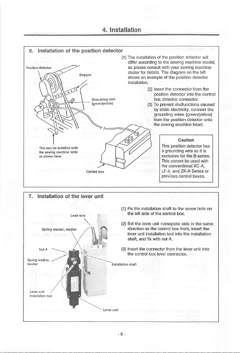
6. Installation of the position detector 8
7.
Installationofthe
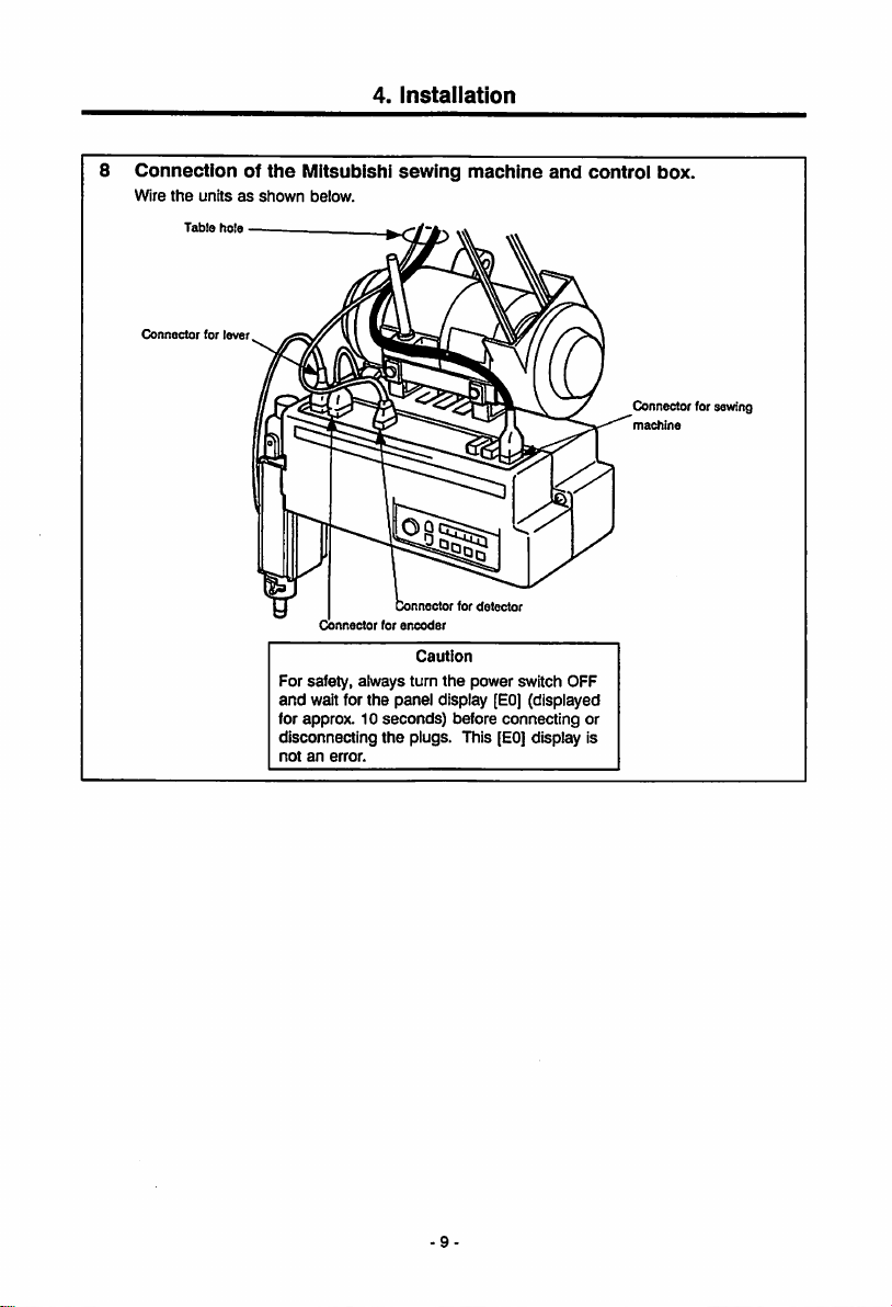
8. Connection of the Mitsubishi sewing machine
lever
unit
and
control box 9
1
3
5
6
6
6
8
5. Wire
and
Grounding
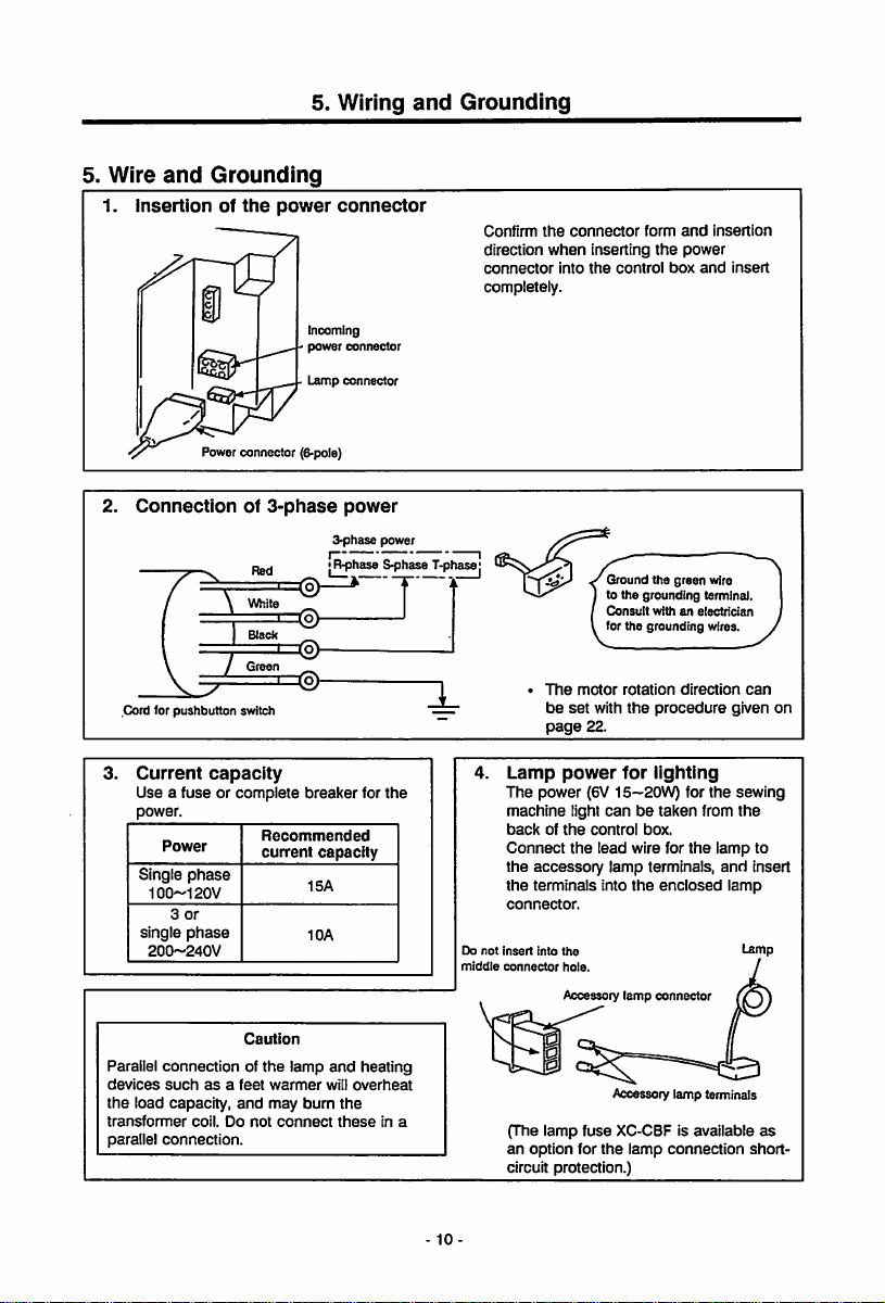
1. Insertion of the power connector 10
2. Connection of
3-phase
power 10
3. Current capacity 10
4. Lamp power for lighting 10
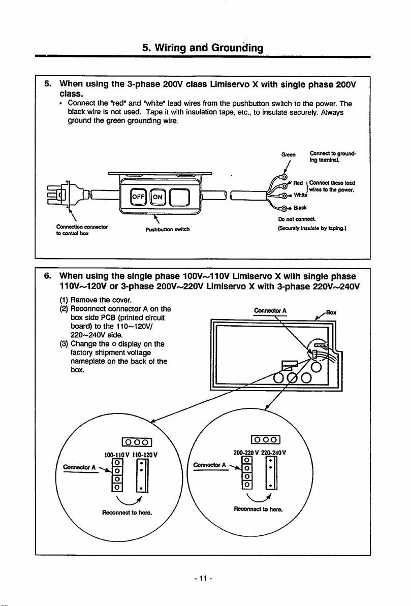
5. When using the
phase
200V
6. When using the single
single
phase
with
3-phase
6.
Confirmation
3-phase
200V
class
Limiservo X with single
class
phase
100V~110V Limiservo Xwith
110V~120V or 3-phase 200V'-220V Limiservo X
220V~240V 11
1. Before turning switches on 12
2. Turn on the power 13
7.
Adjustments
1. Adjustment of
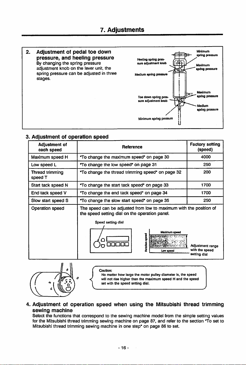
2. Adjustment of pedal
3. Adjustment of operation
4. Adjustment of operation
stopping
toe
position 15
down pressure,
and
heeling
pressure
speed
speed
when using the Mitsubishi thread
trimming sewing machine 16
10
11
12
15
16
16
Page 3
8.
Pedal
Operation
9.
Operationofthe
Operation
1. Displays during normal
2.
Selectionofeach
3.
Howtouse
No.1 To
No.2 To
No.3 To
No.4 To
the
change
change
start
sewing with a siow start 23
useasa
(to
use
an external switch) 23
No.5 To apply a
4. Displays
and
functions of
5. Before operating
6. How to
No.1 To
7. How to
No.1 To
use
the
set
the no. of stitches for the start/end V tacking
start
tacking
tacking
retract
use
the
change
(Ex. to
changeto4500 rotations) 30
No.2Tochange
No.3 To
No.4 To
No.5
change
(Ex. to
change
change
(Ex.tochangeto1200
To
change
(Ex.tochangeto1500
No.6
To
change
(Ex.tochangeto300
No.7 To
No.8
No.9
change
(Ex.tochangetothree
To
carry
out
switch
To
stitch
SOH
with
Panel
Keys
mode
and
functions of
mode
normal
mode
the
rotation direction 22
the
needle position during
standing
weak
the
tacking
work
type
sewing machine
brake during stopping 24
each
key in
the
keys for the program
mode
each
stop
tacking
mode
key 18
mode
and
retractto4
program
the
maximum
the
low
the
needle
stitches,
mode
speed
speed
(Ex.tochangeto200
lifting
speed
and3stitches
for
the
end
rotations)[p..
to 180 rotations) 32
the
start
tacking
speed
rotations) 33
the
end
tacking
the
slow
the
numberofstitchesinslow
low
speed
+
SO
one
needle
speed
rotations)
start
speed
rotations) S
stitches) SLN
operation
with
the
[v]
with
external
start
external
switch
SOH
+ SO .
17
18
19
22
22
25
23
28
28
30
31
34
35
36
37
38
Page 4
No.10Toconfirm
the position where the needle passed through
the fabric and to raise the penetration strength of the first
+
stitch
with
the
external
switch
SOH
No.11 To stop tacking withexternal switch
SO
SOH
+ SO
No.12 To bring the one shot function outside and use as the
manual/automatic sewing selection switch for test stitching,
etc.
SOH
SHM
No.13 To carry out automatic operation
(one shot operation) SH + SHM
No.14Toset
No.15 To
No.
16 To delayset
No.17 To execute emergency
No.18 To continue presser foot
No.19 To continue presser foot
No.20
No.21 To not
No.22Toprotect
No.23
No.24 To
No.25
No.26
the
numberofstitchestothe
after detecting the fabric
(Ex. to
set
to 10 stitches) UES + PSU
set
the
numberofstitchestothe
after
the
fabric
endisdetected
(Ex.
set
to 10 stitches) PS + PSD
position
sensor,
operates
etc.,
PS
and
+
detection
restart
PSN
end
even
stop
lifting
lifted
FUM
lifting
and to lowerthe presser foot after the time
has passed
To stop presser foot
heeling,
foot
lifting
To make a
lift
FUM|
+ |FU| 48
lifting
needle
lift
signal
use
automatic
with light heeding) S3L
when
half-stitch
the
needle
the
with
presser
thread
with
the
after
(S2)|FL
trimming
the backstitchswitch| S7 | 52
backstitch switch
needleUPposition
with an optical sensor, etc.
DOWN position
with
the
optical
sensor,
(DOWN
when optical
stop)
with
sensor,
optical
etc.,
during sewing UES
after the needle is
after the needle is
lifting
needle
lifted,
set
on the timer
with
the
[
foot
lifting
(to
stop
presser
knife
does not
S7
When the tip of the needle is stuck in the thick fabric after
thread
Tooperate the backstitch solenoidsimultaneously
trimming
ITBI 55
with
39
40
41
42
stop
43
stop
etc.
44
45
46
47
full
49
return|6TL|51
trimming
RU
thread
50
53
54
Page 5
No.27 To
No.28 To set for a different manufacturer's thread
No.29
No.30
No.31 To
No.32 To
8. How to
No.1
No.2 To
use
a sewing machine that
thread trimming S2R
(Ex.
to set to
Brother
Model
To reverse runto the settingangle
with
full
heeling
and needle
-i-nn
does
8716)|TR
from
lift
signal
not have automatic
trimming
sewing machine
| 57
the
DOWN
position
(S2)|TR
| 58
To drivethe backstitchsolenoid duringstopping IS7 59
stop
start
tacking with the external switch
stop
end
tacking with the external switch PS 61
use
the program mode 62
To adjust the pedal toe down amount
to
sew
high
change
speed
quickly at a high
the time for the sewing machine to reach the
(Ex.
to set to
speed)
100ms
ROC 62
with
simple
LIES
(Ex.
to set value 55
setting
[h])
No.3 To change the timefor the sewing machineto stop
(Ex.to
set
to 230ms withsimple setting
No.4 When using a sewing machine
with
[L].)
a large
DC
inertia
GA 65
No.5 To operate the sewing machine withoutthe detector when the
detectorisbroken
9. How to
No.1
No.2 To
use
the program mode 67
To change the presser foot holdingstrength
(Ex. to
set
to 33% duty [LO]) FUD
set
the needle position stop angle just before the fabric
looking from the UP position (Ex.to
10. How to
No.1
No.2 To
11. How to
No.1
use
the
program
To output a needle cooler output to the sewing machine
connectorLoutput
fix
the operation panel settings during normal mode
and
tacking
use
the
mode
program
To accurately align tacking (To
tacking
corner
No.2 To carry out continuous tack stitch (To
reverse
to 10
No.3 To aligntacking when start/end tacking
1000
rpm BM
NOS
setto[70°].)
mode
0
NCL 69
PSW
mode
set
the stop time at each
to 100
milliseconds)[D1
| + jCT|
set
stitches)
D2
B
M
speed
08
the W tacking forward and
is less than
[AC
56
60
63
64
66
67
68
69
70
71
71
72
74
Page 6
No.4
Tocorrectthe no. of
No.5
To correctthe no. of reversestitches duringstart tacking|
No.6
To correct the no. of reverse stitches during end tacking|
No.7
To correct the no. of
12. How to
No.1
Howtoview
No.2 To
operation
No.3 To
use
check
check
the
program
the
the
signal
the
forward
forward
mode
error
code
pedal
operation
| Si |,| S2 |,| S3 |,|
motor
and
encoder
stitches
during
stitches during end tacking |
history
pT],
signal or external
PD
signals
No.4 To check the positiondetector signal| UP|, |
No.5
Tocheck each
No.6 To check the presser foot
and
thread
13. How to
No.1 To return ail
14.
Howtouse
No.1 To
15.
Tableofprogram
* Mitsubishi
motor
use
the
the
set
the
machine in
180B
thread
pulley
signal
release
program
settingstothe
program
functions for
one
mode
trimming
diameters
output
mode
mode
the
step
(For example, to
functions
machines
|
6TL
1.1S71.1VR
lifter,
thread trimmer,wiper, backstitch
FUO
TO,WO.
R
factory
settings
[T]
Mitsubishi
simple setting values
start
tacking|BT1
[2],
EGA
Ieca
M.1DN
DN
[T]
.
.
EGB
PG
|
BO
. LO
RESET
thread
trimming
set
for the LSI-1180-BIT)
and
BT2
BT3
BT4
sewing
75
76
77
|
78
79
79
80
81
82
83
84
85
85
86
86
88
107
10. HowtoUse
1. Connector layout 108
2. Description of input/output signals 109
3. List of input signal functions
4. To
11. Error Display
12.
Specifications
Table
of digital
the
Option
Connector
useasa standing work type sewing machine 112
display
108
Ill
113
115
116
Page 7

1.
Points
1.
Please
when
of
remove
turning
Caution
your
the
power
foot from
ON.
the
1.
Points
pedal
of
Caution
2. Alwaysturn
the
machine.
the
power OFF
when
leaving
3. Do not
5. Always
7. A high
inspect
the
tester.
The
semiconductor
when
the
tester's
ground
The
S-phase
(green). Always
control circuit with a
parts
voltageIsapplied.
tfie machine.
motor
hasagrounding
ground
voltageIsapplied
machine,sowait10minutes
the
power switch OFF before
cover.
Control
etfcuit
maybedamaged
this.
inside
tfte
after
turning
opening
wire
the
4. Alwaystum
tilting
the
the
needle,orthreading
I]
6. Do not
8. Use
the
single-phase
the
strong
welder.
use
noise
machine away from
the
power switch OFF before
sewing machine
the
Sewing
machine
branched
wiring
motor.
suchasa high
head,
needie.
when
sources
frequency
replacing
using
of
High
voltage
Notso
danger
1 -
Page 8
1.
Points
of
Caution
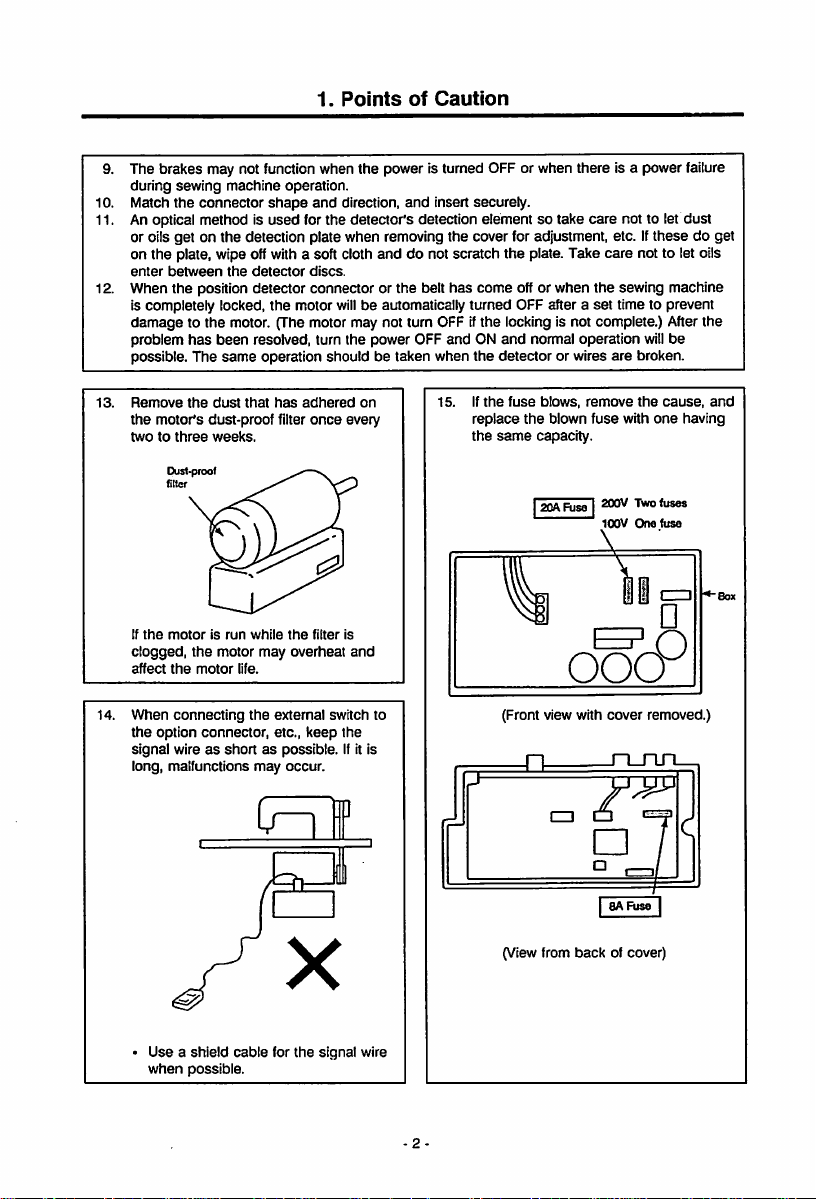
The brakes may not functionwhen the power is turned OFF or when there is a power failure
during
sewing
machine
10.
Match
the
An optical method is
11.
or oils
get
connector
on the detection plate when removing
operation.
shape
used
and
for the
direction,
detector's
and
insert securely.
detection element so
the
cover for adjustment, etc. If
take
care
not to let
on the plate, wipe offwitha soft cloth and do not scratch the plate. Take care not to let oils
enter
between
the
detector
When
12.
the
is completely locked,
position detector connector or
the
discs.
motor
the
belt
has
come
will
be automatically turned OFF after a
off or
when
the
sewing machine
set
time to prevent
damage to the motor. (The motor may not turn OFF ifthe locking is not complete.) Afterthe
problem
has
been
13.
possible.
Remove
the
twotothree
If
clogged,
affect
The
same
the
dust
motor's
dust-proof
weeks.
Dust-proof —N.
filler
the
motorisrun
the
motor may
the
motor
resolved, turn the power OFF
operation should be taken when
that
has
adhered
once
filter
on
every
is
and
life.
while
filter
the
overheat
andONand
the
If
the
15.
replace
the
normal operation will
detector
or wires
fuse
blows,
the
blown
same
capacity.
|20ARjse|
ooo
are
remove
fuse
200V
100V
broken.
the
with
TWofuses
One
these
be
cause,
one
fuse
dust
do get
and
having
14.
When
the
option
signal
long, malfunctions
Useashield
when
connecting
the
connector,
external
etc.,
keep
wireasshortaspossible.
may
occur.
cable
for
the
signal
possible.
switch to
the
Ifit is
wire
(Front view with
n
(View from
back
cover
n_rui
P8AFuse
of cover)
removed.)
I
Page 9
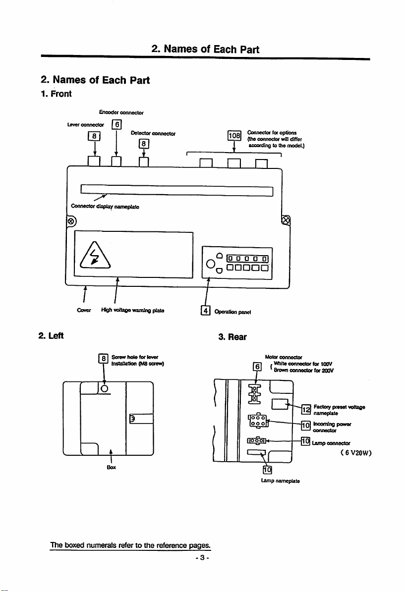
2.
1.
Names
Front
Lever
of
connector
A
Each
Encodcf
Part
connector
2.
Names
of
Each
Part
Connector tor options
(the ccnnecior willrfiffer
according to the model.)
"ID• 0 O
D
Cover Kgh voltaoe warningplate
2.
Left
I 31
Screw
holefor
l"'
installation
o
lever
(M8screw)
41
OperaSoopand
3.
Rear
t5
The
boxed
numerals
refer to
the
reference
pages.
-3-
D1
Motor
connector
WhKe
Brown
I r
»-i
Lamp namepiate
connector
connector
La
I-—'connector
t^0|
(or 100V
(or 200V
Rectory
preset
namepiate
bioocningpower
Lamp
connector
<6 V20W)
voitage
Page 10
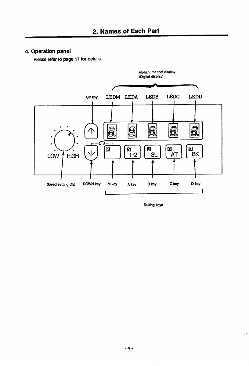
4.
Operation
Please refer to
panel
page
2.
17 for details.
Names
of
Each
Part
LOW HIGH
settSng
dial
Alphanumerical
pgltal
UP
key
LEDM
DOWN
key Mkey Akey Bkey Ckey Dkey
LEDA
•
1-2
LEDB
Setting keys
display)
m
SL
display
LEDC
Q
AT
LEDD
BK
-4
Page 11
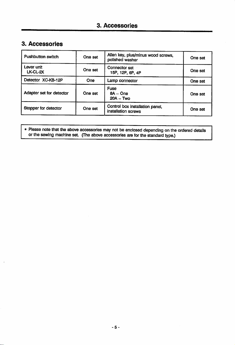
3.
Accessories
3.
Accessories
Pushbutton
Lever
unit
LK-CL-2X
Detector
Adapter
Stopper
switch
XC-KB-12P
set
for
for
detector
detector
One
One
One
One
One
Allen key, plus/minus
set
polished
washer
Connector
set
set
set
15P,
12P,
Lamp
connector
Fuse
8A-One
20A
•••
Two
Control box installation panel,
installation
set
6P,
screws
wood
screws,
4P
* Please notethat the above accessories may notbe enclosed dependingon the ordered
orthe
sewing
machine
set.
(The
aboveaccessoriesareforthestandard
type.)
One
One
One
One
One
dptajlg
set
set
set
set
set
Page 12
4.
Installation
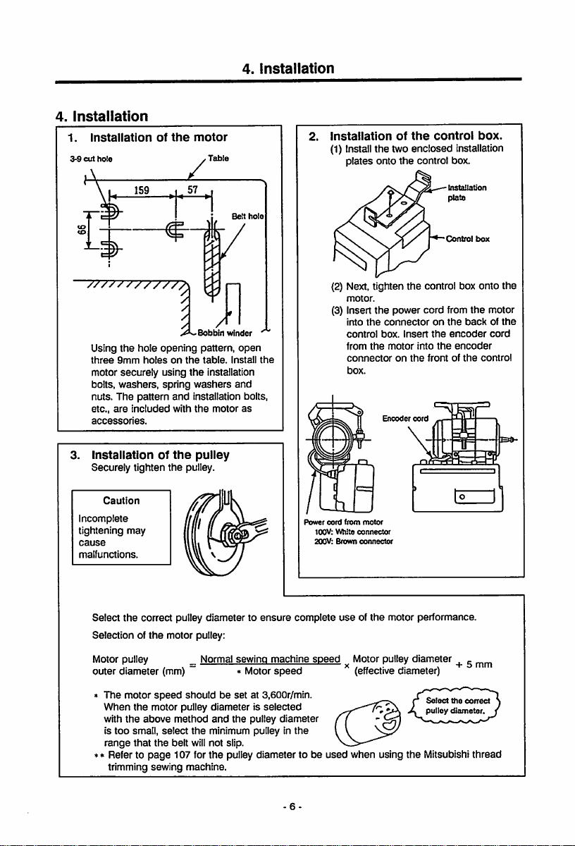
1.
3-9
Installation
cut
hole
4.
Installation
of
the
motor
Table
Belt
hole
instaiiation
(1) Install the two enclosed installation
plates
onto
of
the
the
controi
control box.
Corttrol
box.
box
Bobbin
winder
Using
the
hole
opening
pattern,
three
9mm
motor securely using
bolts,
washers,
nuts.
The
etc.,
are
included
accessories.
3.
Installationofthe
Securely tighten
Caution
holesonthe
spring
pattern
and
with
the
the
washers
installation bolts,
the
puiiey
pulley.
table.
Install
installation
motor
open
and
as
Incomplete
tightening
cause
malfunctions.
may
Select
the
Selection of
correct pulley diameter to
the
motor pulley:
k/lotorpulley _ Normal sewing machine
outer diameter (mm) ~ • Motor
The
motor
speed
When
with
the
is
too
range
* Refer to
trimming
the
above
small,
that
page
sewing
shouldbeset
motor
pulley
method
select
the
the
belt will not slip.
107 for
machine.
at 3,600r/min.
diameterisselected
and
the
pulley
minimum puiiey in
the
pulley diameter to be
the
ensure
speed
Power
complete
diameter
the
(2) Next, tighten
motor.
(3) Insert
into
control
from
connector
box.
cord
from
100V:
White
Brown
connector
connector
200V:
useofthe
speed
Motor pulley diameter
(effectivediameter)
used
when
the
the
power cord from
the
connectoronthe
box.
Insert
the
motor
on
the
Encoder
motor
motor performance.
using
the
control box
the
into
the
frontofthe
cord
Select
pulley
Mitsubishi
the
backofthe
encoder
encoder
+ 5
the
correct
diameter
onto
motor
cord
control
mm
thread
the
6-
Page 13
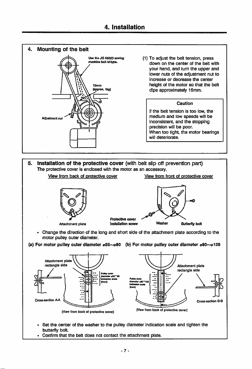
4.
Mountingofthe
Adjustment
4.
Installation
belt
Use the JIS K6323 sewing
ntacMne lielt M-type.
ISmm
^pfox.
1kg)
nut
(1) To adjust
downonthe
your
hand,
lower
nutsofthe
increaseordecrease
heightofthe
dips
approximately
If
the
belt
medium
and
inconsistent,
precision
When
too
will
deteriorate.
the
belt tension,
centerofthe
and
turn
the
adjustment
motorsothat
1Smm.
Caution
tensionistoo
low
speeds
and
the
willbepoor.
tight,
the
motor
press
belt
upper
the
center
the
low,
will
stopping
bearings
with
and
nut to
belt
the
be
5. Installation of
The protective cover is
View
from
Attachment
•
Change
the
motor
pulley
(a)
For
motor
pulley
Attachment
rectangle
Cross^section AA
Set
butterfly bolt.
Confirm
plate
side
(Viewfrom back of protective cover)
the
centerofthe
that
the
protective
enclosed
backofprotective
plate
direction of
outer
outer
the
diameter.
diameter
washertothe
the
belt
does
cover
with
the
motorasan accessory.
cover
Protective
tnstallafion
long
and
short
055~08O (b) For
PuNay
outer
diameler
•SS'^60
irrdiettioA
•e«l«
(Irertt)
pulley
not
contact
the
(with belt slip off prevention part)
View
from
frontofprotective
—caQ
cover
screw
sideofthe
PuBeyOuter
tfARMter
Indlcetioo
^ronl)
(View
diameter
attachment
motor
eflO^ISS
tcele
trom
indication
Vlfesher
attachment
pulley
outer
l>ackofprotective
scale
plate.
Butterfly bolt
plate
accordingtothe
diameter
Attachment
rectangle
cover)
and
tighten
plate
side
Cross-secUon
cover
08O~0l25
B-B
the
-7
Page 14
7.
Installation
spring
Spring washer,
washer
Lever
unit
Installation
tool
wssher,
/
of
washer
the
lever
unit
•
(1) Fix
the
(2)
Set
directionasthe
lever
shaft,
(3) insert the
the
7nstallation shaft
the
Installation shaft to
left
sideofthe
the
lever unit
unit
installation
and
fix
with
connector
control
box
This position
a
grounding
exclusive
This
cannotbeused
the
conventional
LF-A
and
previous control
the
control
box.
n^eplate
control
t>ox
tool
into
nut
A.
from
lever
the
connector.
Caution
detector
wiresoit is
for
the
B-series.
XC-A,
ZK-A
Series
boxes.
screw
sideInthe
front,
insert
the
installation
lever unit into
hole
has
with
or
on
same
the
Page 15
8
Connectionofthe
Wire
the
unitsasshown
Table
Connector
for
hole
lever
For safety, always turn
and
for approx. 10
disconnecting
notanerror.
4.
Installation
Mitsubishi
below.
Connector
sewing
for
encoder
onnector
Caution
the
wait for the panel display
seconds)
the
before connecting or
plugs. This
machine
for
detector
and
power switch OFF
[EO]
(displayed
[EO]
display is
controi
Connector for sewing
machine
box.
-9
Page 16
5. Wiring
and
Grounding
5. Wire
and
1.
Insertionofthe
Power connector (6*pole)
2.
Connectionof3-phase
.Cord for
pushbutton
3.
Current
Useafuseorcompiete
power.
Power
Single
phase
1G0~120V
3
or
single
phase
2G0~240V
Grounding
power
rted
White
Green
switch
capacity
Recommended
current
connector
Incoming
power
Lamp
Sybase
jR-phase
breaker
capacity
ISA
1GA
connector
connector
power
for
power
Sybase
the
T-phase;
X
Confirm
direction
connector
completeiy.
[3o
not
middle
the
when
The
be
page
Lamp
The
power
machine
backofthe
Connect
the
accessory
the
terminals
connector.
insert
Into
connector
connector
inserting
into
the
control
Ground the green wire
to the grounding terminaJ.
Consult
for the grounding wires.
motor
rotation
set
with
the
22.
power
for
(ev
15—20W) for
light
canbetaken
controi
the
lead wire for
lamp terminals,
into
the
the
hole.
Accessory
lamp
form
and
insertion
the
power
box
and
withanelectrician
direction
procedure
iighting
the
from
box.
the
iamp to
enclosed
connector
insert
given
and
iamp
can
on
sewing
the
insert
Lamp
Parailei
devices
the
load
transformer
parallel
Caution
connectionofthe
suchasa
capacity,
feet
and
coil.Donot
connection.
lamp
warmer
may
connect
burn
and
will
overheat
the
these
heating
in a
-10-
Accessory lamp terminals
(The
lamp
option
fuse
for
the
an
circuit protection.)
XC-CBF is available
iamp
connection
as
short-
Page 17
5.
When
using
class.
• Connect the "red*and
the
5. Wiring
3-phase
"white"
and
Grounding
200V
class
LImlservo X with
single
lead wires from the pushbutton switch to the power. The
black wire is not used. Tape itwith insulation tape, etc., to insulate securely. Always
ground
the
green
grounding wire.
phase
200V
Connect to ground-
Ing temtlncl.
Connection
comwctor
to
control
liox
6.
When
using
the
110V'-'120Vor3-phase
(1)
Remove
the
(2)
Reconnect
box
board)tothe
220~240V
(3) Change the o display on the
factory shipment voltage
nameplateonthe
box.
cover.
connector
side
PCB (printed circuit
110—120V/
side.
lOOOi
lOO-UOV
o
\
Pushbutton
switch
single
phase
100V~110V Limiservo X with
200V~220V Limiservo X with
A on the
backofthe
110-120
V
Connector
RedIConnect
Whte
Do
not
oonnecL
(Securely Insulate by taping.)
3-phase
these
(wirestothe
single
phase
220V~240V
lead
power.
Reconnecttohere
Reconnecttohere
11
-
Page 18
6.
Confirmation
6.
Confirmation
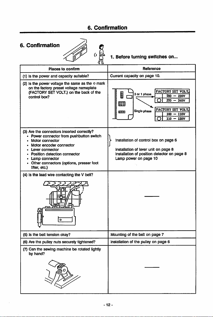
1.
Before
turning
switches
on.
Placestoconfirm
(1) Is the power
(2) Is the power voltage
on
the
(FACTORY
control
(3) Are
• Power
•
Motor
•
Motor
•
Lever
•
Position
•
Lamp
•
Other
lifter,
and
capacity suitable?
the
factory
preset
SET
box?
the
connectors inserted correctly?
connector
connector
encoder
connector
detection
connector
connectors
etc.)
voltage nameplate
VOLT.)onthe
from
connector
connector
(options,
(4) Is the lead wire contacting
sameasthe o mark
back of the
pushbutton
presser
the
switch
foot
V belt?
Current
capacityonpage
lOOOl
n
Installation of
}
Installation of
Installation of position
poweronpage
Lamp
Reference
3 or 1
phase
Single phase
control
lever
10.
FACTORY
700-220V
220-240V
0
FACTORY
100-llOV
110-120V
0
boxonpage
unitonpage
detectoronpage
10
SET
SET
8
VOLT.
VOLT.
6
8
(5) Is the belt tension okay?
(6) Are
the
pulley
nuts
securely
(7) Can
the
sewing machineberotated lightly
by
hand?
tightened?
Mounting of
Installation of
-12-
the
the
belt on
pulley on
page
7
page
6
Page 19
6.
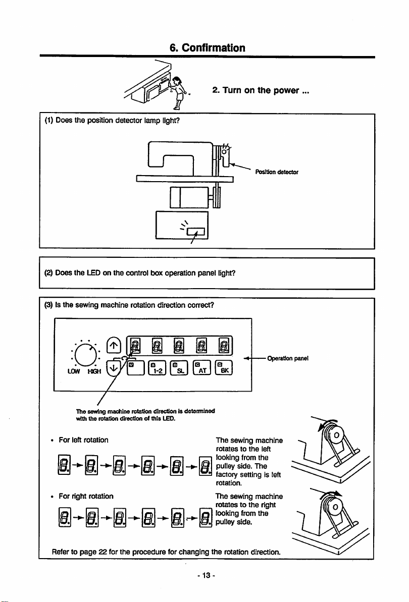
(1) Does the positiondetector lamp light?
Confirmation
2.
Turnonthe
power
Lr
m
I
(2) Does the LEDon the control box operation panel light?
(3) Is the sewing machine rotation direction correct?
0
IB
@ B §
B
B
LOW H3GH
The sewing machine rotationdirecdon is determined
with
the
rotadon
For
left
rotation
For right rotation
dfrectionofthis
LEO.
Cl
SL
BK
AT
The sewing machine
rotatestothe
looking from
pulley
factory setting is left
rotation.
The
rotatestothe
looking from
pulley
Position
-Operation panel
left
the
side.
The
sewing machine
right
the
side.
detector
Refer to
page
22 for the
procedure
for
changing
the
rotation direction.
13
Page 20
6.
Confirmation
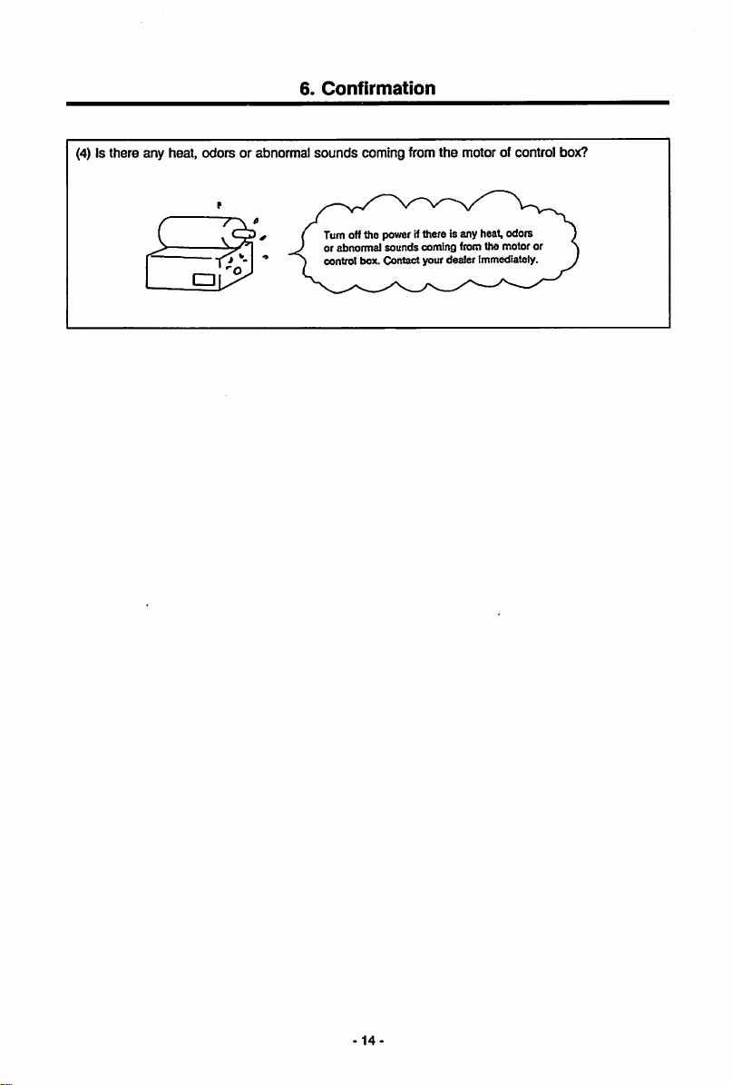
(4) Is there any heat, odors or abnormal
sounds
coming from the motor of control box?
Turnofftfie powerifttiere is any tieat,odors
or
abnormal
sounds
coming
control box. Contact your dealer Immediately.
from the motor or
14
Page 21
7.
Adjustments
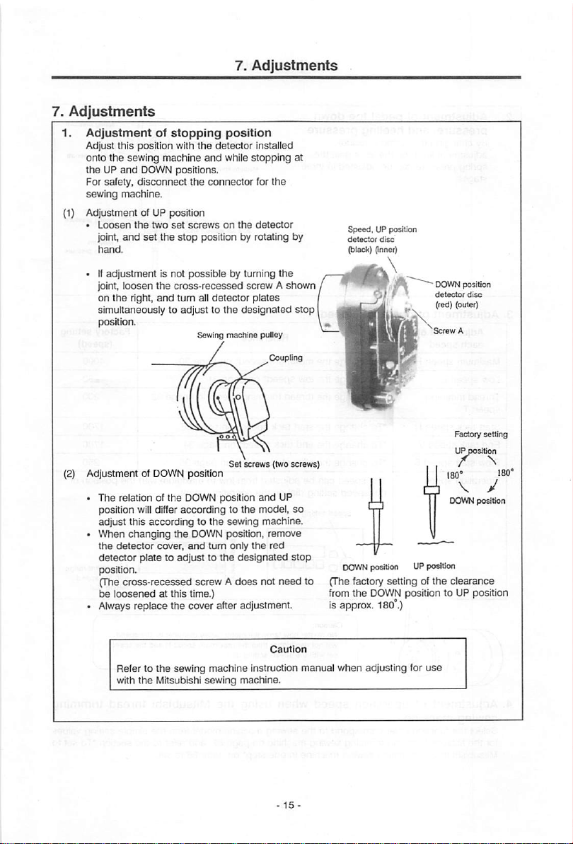
1.
Adjustmentofstopping
Adjust this position with
onto
the
sewing
theUPand
For
safety,
machine
DOWN
disconnect
sewing machine.
(1) Adjustment of UP position
•
Loosen
the
two
right,
set
DOWN
set
the
is not
the
and
joint,
and
hand.
• If
adjustment
joint,
loosen
on
the
simultaneouslytoadjusttothe
position.
Adjustment of
•
The
relation of the DOWN position
position willdifferaccording to the model,
adjust
this
changing
detector
plate to
accordingtothe
cover,
•
When
the
detector
position.
(The
cross-recessed
loosened
be
• Always
replace
at this time.)
the
position
the
detector
and
positions.
stop
cross-recessed
turn
the
adjusttothe
while
the
connector
screwsonthe
position by rotating by
possible
by turning the
all
detector
Sewing
machine
Set
position
sewing machine.
DOWN position,
and
turn
only
screwAdoes
cover
after adjustment.
installed
stopping
for
the
detector
screwAshown
plates
designated
pulley
screws
(two
and
UP
remove
the
red
designated
not
need
at
stop
screws]
so
stop
(The factory setting of
to
from
is
approx.
Speed.
UP position
detector
disc
(black) (Inner)
• DOWN position
detector
(red) (outer)
DOWN
position UPposition
the
the
DOWN position to UP position
180°.)
disc
Factory
clearance
setting
Refer to
with
the
the
sewing
Mitsubishi
machine
sewing
instruction
machine.
manual
when
adjusting for
use
Page 22
7.
Adjustments
2.
Adjustmentofpedal
pressure,
By
changing
adjustment
spring
stages.
3.
Adjustmentofoperation
Adjustment
each
Maximum
Low
speed
Thread
speed
Start
tack
End
tack
Slow start
Operation
pressure
speed
speed
L
trimming
T
speed
speed
speed
speed
and
heeling
the
spring
knobonthe
canbeadjustedinthree
of
H "To
N
V
S
toe
pressure
lever unit,
change
To
change
To
change
To
change
To
change
To
change
The
the
speed
down
pressure
speed
speed
Speed
Oo
Heeling
tpring
tura
pfes-
ttdjuxtment knob
the
Medium spring
Too down spring pressuto adjustment
Reference
the
maximum
the
low
the
thread
the
start tack
the
end
the slow start
can
be adjusted from low to maximum with the position of
setting dial on
salting dial
/
speed"onpage
speed"onpage
trimming
speed"onpage
tack
speed'onpage
speed'onpage
the
operation panel.
/
pretsjte
Imb
Minimum spring pressure
/
30
31
speed"onpage
33
34
35
Maximum
32
tpeed
I
•••••
1
£
Lowtpeod
Minimum
spring
pressuro
Maximum
tpring prossuro
Maximum
spring pressure
Medium
spring pressure
Factory
setting
(speed)
4000
250
200
1700
1700
250
Adjustmentrange
with the
speed
setting
dial
4.
Adjustmentofoperation
sewing
Select
for
Mitsubishi
machine
the
functions that correspond to the sewing machine model from the simple setting values
the
Mitsubishi thread trimming sewing machine on
thread
trimming sewing machine in
Caution;
No
will not rise
set
speed
matter
with
how large the
higher
the
speed
when
one
16
than
setting
using
step* on
motor
the
dial.
page
pulley
maximum
the
Mitsubishi
87,
page
diameter
speedHand
and
refer to
86 to set.
Is,
the
speed
the
speed
thread
the
section "To
trimming
set
to
Page 23
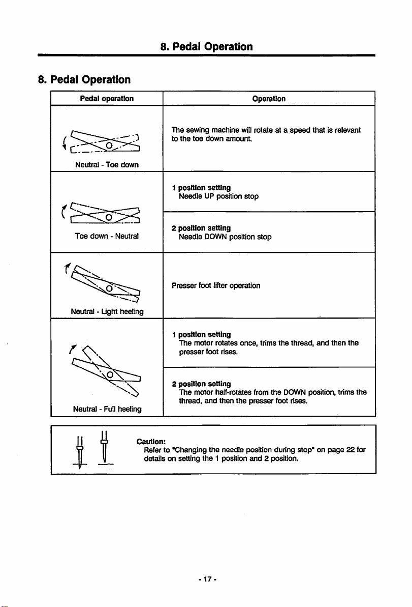
8.
Pedal
Operation
Pedal
operation
8.
Pedal
Operation
Operation
Neutral-Toe
Toe
down-Neutral
Neutral - Light heeling
down
/'O.
Neutral - Full heeling
The sewing machine willrotate at a
to
the toe
down
amount.
1
position
setting
Needle UP position
2 position
setting
Needle DOWN position
Presser
foot lifteroperation
position
1
2
setting
The
motor
presser
foot rises.
position
setting
The
motor half-rotates from
thread,
and
rotates
then
once,
the
stop
presser
stop
trims
the
foot rises.
speed
that is relevant
the
thread,
and
then
DOWN position, trims
the
the
1
1
Caution:
Refer to
'Changing
detailsonsetting
the
-17-
the
needle
1 position
position during stop* on
and
2 position.
page
22 for
Page 24
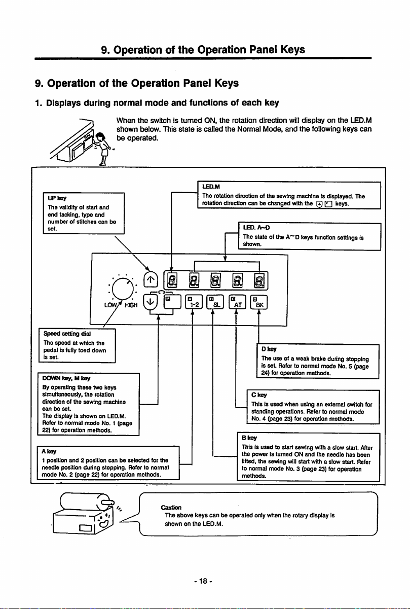
9.
9.
Operationofthe
1.
Displays
UP key
The validity of
end
numberofstitches
Speed
The
pedal
Is
set.
DOWN key, M key
By operating
simultaneously,
direction of the sewing machine
canbeset.
The
Refer to normal
22) for operation
Akey
1 position
needle
mode
during
start
tacking, type
setting dial
speed
is fully
displayisshown
and
position during
No. 2 (page 22) for operation methods.
and
at which the
toed
down
these
two keys
the
rotation
mode
methods.
2 position
and
can
LOWT* HIGH
on LED.M.
No. 1 (page
stopping.
Operationofthe
Operation
normal
be
canbeselected
When
the
shown
be
operated.
Refer to normal
mode
switch is
below. This
•
for the
and
Operation
Panel
turned
state
Keys
functionsofeach
ON,
the
is called
LED.M
The rotationdirection of the sewing machine is displayed. The
rotation
• (D Q
1-2
SL
Panel
Keys
key
rotation direction will
the
Normal Mode,
direction
canbechanged
LED.
A-O
Thestate ofthe A~D keys
shown.
R
AT
BK
Dkey
The use of a weak brake duringstopping
set
is
24) for operation methods.
Ckey
This Is
used
standing
No. 4 (page 23) for operation
Bkey
This is used to start sewing with a slow start. After
the
poweristurnedONand
lifted, the sewing willstart with a slow start. Refer
to normal mode No. 3 (page 23) foroperation
methods.
displayonthe
and
the
with
the0P~|
Referto normalmode No. 5 (page
when using an extemal switch for
operations.
Refer to
following keys
keys.
function
settingsis
normal
methods.
the
needle
has
LED.M
can
mode
been
Cautkm
The
above
shownonthe
keys
canbeoperated
LED.M.
18
only when the rotary display is
Page 25
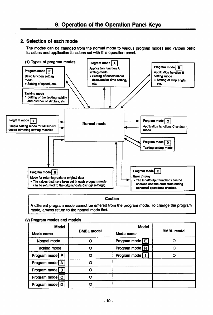
2.
Selection
The
modes
functions
(1)
Typesofprogram
Program
Basic (unction setting
mode
• Setting of
Tacking
* Settingof the tacking
and
numberofstitches,
Program
mode
| i |
Simple setting
thread trimming sewing
mode
Program
Mode for returning
• The values
can be returned to the ortginaldata (factoiysettings).
of
canbechanged
and
application functions
mode
I p |
speed,
etc.
mode
for Mitsubishi
machine
mode
that
9.
Operationofthe
each
mode
from
modes
validity
etc.
Normal
data
to original
have been set In
data
each
Operation
the
normal
set
Program
Applicationfuncfion A
setting
« Setting of acceleration/
program
mode
with this operation panel.
mode
| A|
mode
deceteration tinne setting
eta
mode
mode
Panei
to various program
Program
Appiication
mode
Program
Tacking setting
Program
mode}
Error display
• The input/output functions can tie
checked
abnormal operationschecked.
Keys
modes
and
Program
mode
Application function B
setting
mode
• Setting of stop angle,
eta
mode
[c |
functions C setting
mode
| p |
mode
E|
and
the
error
state
various
| b j
during
basic
A different program
mode, always return to
(2)
Program
Mode
modes
name
Normal
Tacking
mode
mode
Model
and
mode
the
models
Programmode| P | O
Programmode| A | O
Program
mode| B | O
Program
mode
Program
mode
cannotbeentered
normal mode first
BMBL
model
O
O
O
O
Caution
from
the
program mode. To
Model
Mode
name
Program
mode
fil
Programmode|°R| O
Program
mode
fTl
-19
change
BMBL
the
0
O
program
model
Page 26
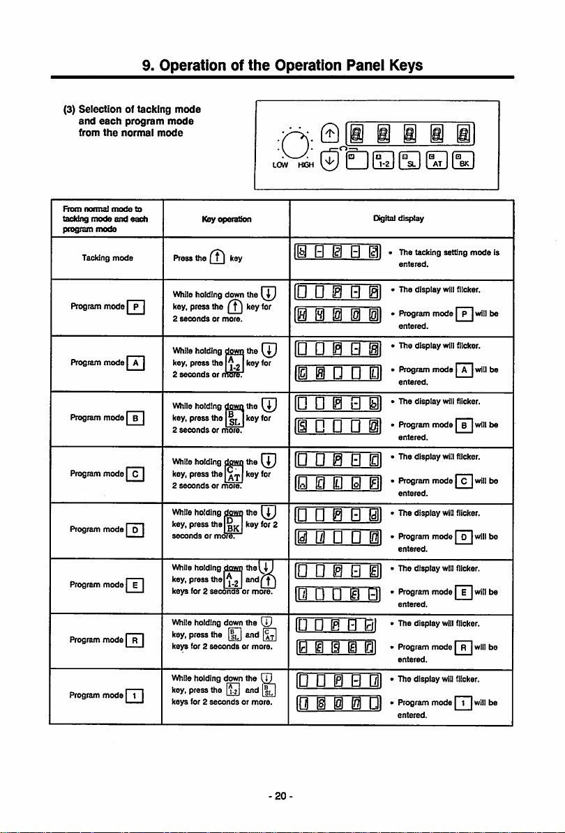
(3)
Selectionoftacking
and
each
notmal
mode
the
mode
normal
modeto
and
mode
program
from
From
taddng
program
Tacking
9.
Operationofthe
mode
mode
mode
each
Press
the key
Key
operation
Operation
011
11^
El
Panei
Q
@1•The
Keys
i
Digital
IBS
ID Q 0
SL AT BK
display
tacking
entered.
setting
mode
is
Program
Program
Program
Program
Program
Program
Program
Program
mode
mode
mode
mode
mode
mode
mode
mode
| p |
[ A|
| B |
| C |
| p [
| E |
[ R |
| i |
While holding down the
key,
press
the key for
2
secondsormore.
Whileholding dowri the
key,
press
f'lo1^j
2
secondsorrmSrST
While
holding
press
the |
holding
press
fitol
press
f>te key for 2
holding
press
the
for 2
secondiormore.
holding
press
the
secondsormore.
holding
press
the
for 2
secondsormore.
dowri
dowij
^tI
down
down
[|2
down
key,
2
secondsormore.
While
key,
2
secondsormore.
While holding dowri the
key,
secondsormof^.
While
key,
keys
While
key,
keys for 2
While
key,
keys
the
Ijrj
key
for
the
the^J
(i)
the
[p
and
[|3
the
Q]
and
l|n
fill
D ® 0
10 0
10 D 0
IIS
0 • n Bl '
' '
IE)
0 @ 0 0] *
@1*tl'spiay
IS
0 01 •
El
0l *
10 0 0 0 0l *
10 0 @ 0 0! *
10 0 0 0
@1•P'«>sram
r0 0 @ 0 0] *
10 0 0 0 01 *
rO 0 0 0 0] *
0 0 0 0
ID 0 E 0 01 *
10 E @HI01 »
0l*Program
r0 0 0 0 Ql *
[Q H 0 0 01 *
Program
mode
entered.
display
Pwgiam
mode
entered.
display
PfogtaAT
mode1B[will
entered.
mode
entered.
display
Program
mode
entered.
'"®P'®y
mode
entered.
display
Program
mode
entered.
display
Program
mode]t[will
entered.
will
will
will
will
^"1
will
will
| p
fT)
| D
| E|
Er~|
flicker.
flicker.
[will
flicker.
will
flicker.
will
flicker.
[will
flicker.
will
flicker.
will
be
be
be
bo
be
be
bo
be
20-
Page 27
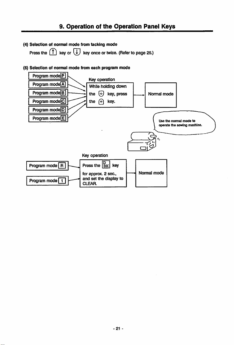
(4)
Selectionofnormal
Press
the
(Tl
(5)
Seiectionofnormal
Program
Program
modeQ
Program
mode[B]
Program model
Program
modefol
Program
Program
mode
Program
mode
9.
Operationofthe
mode
keyor[5
mode
modeE
modefll
[r^
[T]
from tacking
key
onceortwice.
from
each
Key
operation
While holding
the
0
the
Q
Key
operation
Press
the
for
approx.2sec.,
and
set
the
CLEAR.
mode
program
key,
key.
D
key
BK
display
Operation
(Refertopage
mode
down
press
to
Panel
Normal
25.)
Normal
mode
Keys
mode
Use
the
operate
normal
the
mode
sewfng
to
machine
-21
-
Page 28
3.
Howtouse
9. Operation of
the
normal
mode
the
Operation Panel Keys
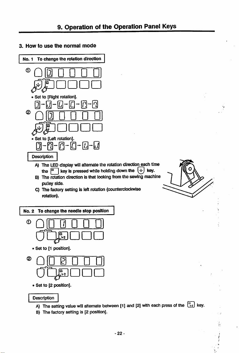
No. 1 To
change
the
OB
•
'Q
Set
0-
Set
D U U 0
to [Right rotation].
3~0~[3 lcl~0
0 • • • •!
to [Leftrotation].
rotation
direction
0-@-0-0-0-y
Description
The
LED
display
wili
alternatethe
the1°I
B)
The
pulley side.
C) Thefactorysetting is leftrotation(counterclockwise
rotation).
No. 2 To
®
Qin
keyispressed
rotation
change
the
0 • • •!
direction
needle
isthat
stop
while
looking
position
rotation
holding
down
from
direction
the
the
sewing
each time
key.
machine
*
Set
to [1 position].
®Qjg 0 • •
0
CjpZI
*
Set
to [2 position].
Description
A)
The
setting
B) The factory setting is [2 position].
Dn
value
will
ni
CD
alternate
between
22-
[1]
and
[2]
with
eachpressofthe
fin
Li±J
key.
Page 29
9. Operation of
the
Operation Panel Keys
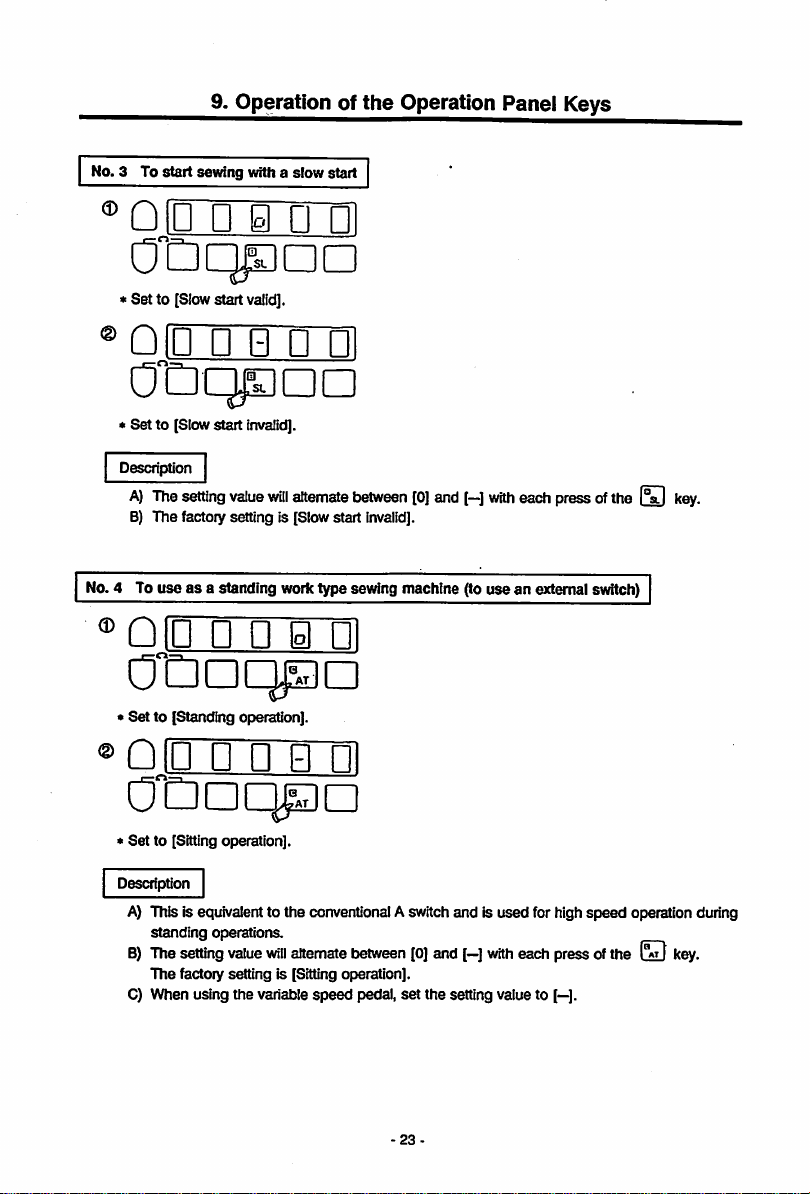
No. 3 To
start
sewing with a slow start
"^QlU • H n p]
* Set to [Slow start valid].
®QIU • B • PI
OtDqpoD
• Set to [Slowstart invalid).
Description
A)
Thesettingvalue
B) The factory setting is [Slowstart
No.4 To use as a standing worktype sewing machine (to use an externalswitch)
will
alternatebetween[0]and
invalid].
[—]
with
each press ofthe
Q IP P P H PI
OtlDC^D
• Set to [Standing operation].
key.
®
Qip
p p n PI
Otiaqpn
*
Set
to [Sitting operation].
Description
A) This is equivalentto the conventionalAswitch and Is used for high
standing
8)
The
The factory setting is [Sitting operation].
C) When using the variable
operations.
setting
value
vrill
alternate
tjetween
[0]
and
speed
pedal, set the setting valueto
-23
[—]
with
speed
each
pressoftheQkey.
[—].
operation during
Page 30
9. Operation ofthe Operation Panel Keys
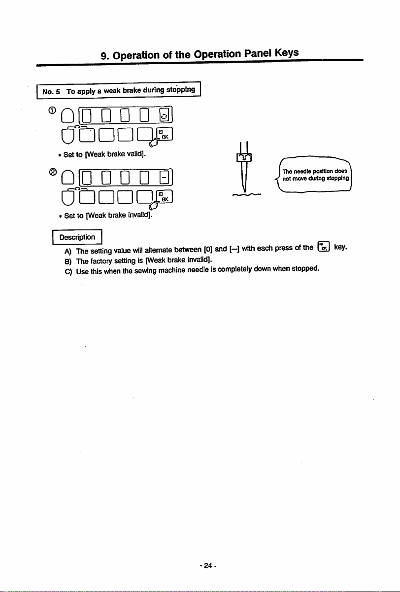
No.5 To applya weakbrakeduringstopping
®nin
«Set to [Weakbrake valid].
®Qin
• Set to [Weak brake
Description
A)
B)
C)
The
The
Use
n • u
n • •
setting
value
factory
settingIs[Weak
this
when
invalid].
will
the
sewing
B1
alternate
between
brake
machine
[0]
and
[—]
with
invalid].
needleiscompletely
down
The needle position
not move during stopping
each
pressofthe
when
does
L®eJ
stopped.
24
Page 31

9. Operation of
the
Operation Panel Keys
4. Displays
(1) Types of tacking modes and key operations
Normal
and
functions of
mode
Qkey
key ON
each
key in
ON
Tacking
setting
• Setting of the start tacking
validity
Setting of the end tacking
validity
t
(2) Tacking
When
the
mode
will
setting
mode
(T)
keyisturned
be entered. The
ON,
validity
and type of start and end tacking can be
Qli
Sstting of ttftft tscldng validity
<0i8ptay
ox,>
0 :
Valid
Q :
Invalid
Setting of start tackingtype
< Display ex. >
: No
tacking
1/]:V
tacking
LU
:
Ntacking
: M
tacking
:
Wtaddng
^
the
tacking
mode
and
type
and
type
will
display
above
B g B B
mode
Tacking
mode
Qkey
ON
No. of tacking stitch setting
mode
• Setting of the no. of
0
key
ON
Qkey
ON
the
jkey,
Factory setting
Setting of end tacking type
< Display
ex.>
: No tacking
:V
tacking
: Ntacking
: Mtacking
: W tacking
Setting ot
validity
< Display ex. >
stitches
tacking.
and
0^
0
the
set
end
for
tacking
startorend
tacking
here.
s
^
^
:
Valid
:
Invalid
setting
-25-
Page 32

9. Operation of
(3) No.Oftacking stitches setting mode
When
the@keyIsturnedONagain,
of
stitches
canbeset
the
Operation Panel Keys
will
displayontheQkey
indicator,
and
the
no.
Caution
Refertothe
display"onpage
the
correspondenceofthe
digital display
alphanumerals.
No.ofstitctres
A
setting
No.ofstitcfies
B
setting
Each setting value
0 to 9
stitches.
Ais10
stitches
8 Is11stitches
CIS12stitches
D is13stitches
Eis14
stitches
Fis15
stitches
_
116
for
and
canbechanged
A, B,0,D, E, F
^
from
stitches
PH
SrSf
•Factory setting
No.ofst
tones
0 setting
No.ofstitctres
C
setting
26
Page 33

9. Operation of
the
Operation
Panel
Keys
5. Before operating
• Following
Program-
* * *
♦
Normal
Description of
A)
Purpose
• This
B)
Set
names
select
function
the
keys for
the
next section,
£
what kind of operation
name
the
program mode
the
following description method
]
k'mction^-
the
sewing machine makes.
will
be used.
@
Purpose
^
Set
function
© Settingorder
Digital display
Display
descnption—
Mode
trartsition
(g)
Outline
description —
—
name
• The •« displayin | )| Isthefunctionname, and the ••display in | ningi|
value in
the
function.
The
function
name
and
set
value
are
separated
(Whenone functionis used | ( )| , when twoare used | ( Ij+1 (
C) Mode transition
• This Is
D) Setting
•
E) Digitaldisplay
• Press
• The function
• When setting the functionsetting withthe
• When settingtwo or more functions (purposes) in the
•
F) Display description
• This is a description of
G) Outline description
• This is an outline
the
LED d'splay
entered.
order
Setintfie
displayedonthe
mark.
be
orderofnumtiers.
the
key marked with
set
are
name
the
same,
and
LED.
and
setting value will
the
display description displayed first when
the
key
does
mark until
not
the
change
-^key,
needtobe
function
with
ifthe
pressed
(purpose)can be set consecutivelyaftersettingthe first
for
consecutive
The
function
setting.
will
advance
guideofeach
with
each
press
ofthe(J)
the
LEDdisplay contents of the functions set with
condition
when
setting
name
or setting value to t)e
each
pressofthe
LED
displayand the functionsetting to
(reset).
same
program mode,
function
(purpose).Press the key
key
and
will
return
the
functions.
—
Name
with a period (.).
1|
each
program mode is
key marked with
the
second
with
the
the
-e
istheset
.)
used
the
function
key.
mark key.
is
27-
Page 34

6.
Howtouse
9. Operation of the Operation Panel Keys
the
tacking
mode
No.1 To
set
the
tacking retract to 4 stRches, and 3 stRches forthe end tacking
retract
no.ofstRches
Function
iStartl4stitches
for
the
start/endVtacking
setting|blOIOIII+1 M I
3
stitches
•11-
"(Thisindicates the key operation. Referto
QIB
QIB
Enter
the
tacking
B H B Bl
mode
((D)-
OtDDDDa
*
Set
•The tacking
QIB
mode
• B • 01
OtDqpan
*
Set
the
start
[Vtacking].
QIB
Otiaaa^
*
Set
[Vtacking].
tacking seRing to
B B B Bl
the
end
tacking seUing to
willbeentered.
to [Start
Q IB B B H Bl
01
.
Set
to [End tacking valid].
QIB
OtiDDnD
* Complete
and
start
043011
lEndl
B B •
tacking
II
II
B a H Bl
the
tacking setting.
•!
valid].
^
page
20.)
^10
El ElBlEll
CCDDDDD
*
The
no. of tacking
willbeentered.
QjBB H B
*
Set
the
no. of
stitches
start
to [4].
stitches
Bl
tacking
setting
retract
QIB
H B B Bl
cTQpaaD
*
Set
the
no. of start tacking
0
QIB
B B i Bl
*
Set
the
no. of
-28-
end
tacking
advance
advance
stRches to [0].
stRches
to [0].
Page 35

9. Operation of
the
Operation Panel Keys
0 ©
QID • • •
Otianap
»Setthe no.ofend
stitches to [3]. completed.
il
tacking
retract
QlioliigHIil
cJDdddd
»Theno.of
tacking
stitches
setting
has been
©
Description
A)
B) In the tacking setting mode, the
C) Inthe no. oftacking stitches setting mode, the
Return
to the
normal
mode.
( (T))-
Refer
to section
•
Selectionofstart
•
Selectionofend
The setting value
Co];
[-]:
(Both keys are set to [-]:
•
The
The
For both keys: (o): No tacking
(Both keys are
Selection
Selectionofthe
Selectionofthe
Selection
Wheneach ofthe four keys are pressed, the setting value
B,C, D, E, F stitches. A refers to 10 stitches, Bto 11 stitches, C to 12 stitches, Dto 13 stitches, E
to 14 stitches, and F to 15 stitches. (Theno. of all stitches isset to [4] at shipment.)
"Displays
tacking
Start
tackingorend
Start
tacking
patterntostart
patterntoend
ofthe
no.ofstart
no.ofstart
no.ofend
ofthe
no.ofend
and
functions
tacking
validity
validity
will
alternatebetween[0] and (-)
tacking
orend
tacking
invalid
tackingisselected
tackingisselected
(1): V tacking
UK N tacking
C3]:M tacking
(4): W tacking
set
to (Ntacking] at shipment.)
tacking
tacking
tacking
tacking
ofeach keyinthe
following
will
with
I".;!
withEDkey.
valid
invalid
at shipment.)
with
with
forward
reverse
reverse
forward
-(This indicates the key operation. Refer to
page
21.)
tacking
mode"
on pages 25 and 26.
occur.
key.
with
each press of the
the j
the |
following
stitches
stitches
stitches
stitches
with
with
with
with
key.
key.
occur.
the |°.g|
the
the
the
key.
["a.Ikey.
)
key.
[*%;|key.
will
change between 0 to 9 stitches, A.
key.
-29
Page 36

9. Operation of
the
Operation
Panel
Keys
7. Howtouse
No.1 To change the maximum speed (Ex. to change to 4500 rotations)
Enter
the
program
program
mode
mode
Function
( (J) + 0 )-
(Refer
totheTableof
88 to 96.)
setting [ h I
•
(This
Program
4500
fl
indicatesthe keyoperation. Refertopage 20.)
•>
oezzb
OtDDDDO
♦
Program mode | P |
QiD
n
Bi
n 01
OtDqpan
•
Set
to [5].
QID
0 • n
CDaacp)
>
Set
to [0].
Return
tothe
will
be entered. • Set to [4].
ffll
normal
mode.
( + 0 )
qjli
OQpDDD
QID
OtDoqpo
»Set
to [0].
QiB
OtDanoD
• The [H] function setting
completed.
t
(This
indicates
the
key
operation.
Refer to
page
mu u ui
• • @ PI
H a
21.)
a~ii
(The
functions
f
Mode
has
page
Functions
been
Page
88
for
referenceinthe
tableisshown.)
on pages
Description
A) The
setting
B) By pressing
(However,
C)
The
factory
rangeofthe
eachofthe
the
key is only
settingis(4000
maximum
rotations).
speed
between
is 0 ~ 8999 rotations.
keys,
the
setting value will
1 ~ 8.)
30
change
between 0 ~ 9.
Page 37

9.
Operationofthe
Operation
Panel
Keys
No.2 To
®
Description
A)
B) By pressing each of the keys, the setting value
C) The factoiy setting Is [250 s/min].
change
the
low
Enter
program
mode
QiM
H 0 a 01
Ot:nann
Program
mode
Qiu
• H n ni
ODc
>
Set
to [2].
Qin
(1 n
nioii
0
Qooci^^
•
Set
to [0].
Returntothe
The settingrange ofthe
(However,
nomial
the
speed
(Ex. to
change
to 200 s/mln)
Function
(®
setting
+
ffl)
Qia
jStDDDOa
will
be entered. *
Set
QliJ
Ollinqpa
*
Set
QEnm
OtDDDan
>Complete
mod&(CD+(T))
maximum
key is only between 0 ~ 4.)
speed is 0 ~ 499
I L I
200
• n n
function to (L].
• •
to [0].
the
rotations.
H
[L]function setting.
151
ni
ni
Page
win
change between 0 ~ 9.
88
-31
Page 38

9. Operation of
the
Operation Panel Keys
No.3 Tochange the thread trimmingspeed (Ex.to change to 180 rotations)
Enter program
Qi
mode
ElH01
OtiaaDa
♦
Programmode
D ®
Qi'u •
PI
n m
OtDqpna
*
Set
to [1].
D
Qiu
• n
nil
*
Set
to [0].
®
Returntothe
Description
A) The setting range of
B)
Bypressing each ofthe keys,the settingvalue
(However,
C)
The
factory
normal
the (°a.|
setting
Function
(
ai
wiil
be entered. *Set
mode.(CD
the
thread trimming
keyisonly
is [200 s/min].
between0~4.)
setting
It I
IBoTI
QiH
• • n (1
jStDaODD
function
to [T].
oru
• n
O'dnqpa
*
Set
to [8].
QJEOm
ODDDDa
Complete the (I] fitnction setting.
+ 0 )
speed
is 0 ~ 499 rotations.
Bi
ni
(Refertothe Table of
display* on
alphanumerals.)
Page
will
digital
page
116
for
88
change between0 ~ 9.
-32
Page 39

9. Operation of
No.4 Tochange the start tacking speed (Ex.to change to 1200 rotations)
Enter
program
mode (CD+ (T))
Qli
B i i Bl
the
Operation Panel Keys
Function setting n 11200
Qiy
• n n a
OtDDDDO
* Program
QID B • n PI
0 (HID
♦
Set
to (1].
mode
willbeentered.
•
Set
function to [N].
i)
QID
• a n PI
OtiqpDD
•
Set
to [2].
D
QIU
• • i
CT
0"C3DqpD
Set
to [1].
QIB
Q ^ i
ODDDDG
:The [N] function setting
completed.
Description
A) The setting range of the start tacking
B)Bypressing
(However,
C) The factory setting is [1700 rotations],
D) This is effective
eachofthe
the
(D
when
il
has
been
(DOIDIS
keyisonly
aligning
the
§)
Q!•D • D
0
•
Set
speed
is 0 ~ 2999 rotations.
between0~2.)
start tacking.
i1
CDDDIHJi^]
to [2].
Return
tothe
normal
keys,
the
setting
value
moda(
Page
will
change
CD
^ )
88
between0~9.
-33-
Page 40

9. Operation of
the
Operation
Panel
Keys
No.5 To change the end tacking speed (Ex.to change to 1500 rotations)
Enter
program
niH
mode
B i i
ii
(
(J?
Function
+ (2 )
setting
v
nia
11500
• • • PI
•"••••a
♦
Program mode
D @
QJD
H• •
01lIi|3DnD
•
Set
to [1].
QID
• n
will
be entered. * Set function to
ni
»
IS!
PI
[V].
Qin
n gi •
OtiQPDD
Set
to [5],
•
!••••
ni
a
OtDDcpa
*
Set
*
Set
to [0].
nin
Rig]loi
0"Daaaa
m
to [0].
Return
tothe
normal
moda( (J) +
(T)
)
* The [V]function setting
completed.
Description
A) The setting
B)Bypressing
(However,
C) The factory setting is [1700 rotations].
D) This is effective
rangeofthe
eachofthe
the01keyisonly
when
has
end
aligning
been
tacking
(3
the
speed
is 0 ~ 2999 rotations.
S 0
betweeno~2.)
end
tacking.
-34
the
setting
value
will
Page
88
change
between0~9.
Page 41

9.
Operationofthe
Operation
Panel
Keys
No.6 To
Enter
Qii
Program
nn
change
program
a i i
mode
n a
OtDc^aa
*
Set
to [3].
QID
• • •
OtDDDQP
*
Set
to [0].
®
Returntothe
the
slow start
mode
fpl(CD
willbeentered.
rrpi
normal
speed
........
Function
ii
il
mode.(CD
(Ex. to
setting
+ )
change
to 300 rotations)
300
QIH
U • • PI
*
Set
function to [S].
Q iu u n p ni
OTzudd^d
•
Set
to [0].
QiB
• a 0 11
OtDDDDD
* The [S] function setting
completed.
+ (B )
has
been
Page
88
Description
A)
Thisisvalid
B) The setting range of
0)Bypressing
(However,
D)
The
when
eachofthe
the
factory setting is [250 rotations].
the
FsTl
the
speed
(31
keyisonlyo~2.)
keyinthe
normal
is 0 ~ 2999 rotations.
(5i]
(3
-35-
modeisturned
keys,
the
setting
ON.
value
will
change
between0^9.
Page 42

9.
Operationofthe
No.7 To change the number of stitches in siow start (Ex.to change to three stitches)
Enter
program
niH
mode
w isi a HI
(
(XI
+ (2) )
OtDDDDD
*
Program
Qin
mode| P |
n n n H
will
be entered. *Set
O'Daaqp
«
Set
to [3].
Returntothe
Description
A)
Thisisvalid
B) The setting
C)Bypressing
D) The factory setting is [2 stitches].
normai
mode.(CD+(T)
when
theOkeyinthe
range
of the number of stitches is 1 ~ 5 stitches.
PbkI
key,
the
setting
Function
normal
value
will
Operation
setting[SLN
Qiia
gi H n •!
C]eno imiiij
functionto[SLN].
QiB
OtnoDDp
»
The
[SLN] function setting
compieted.
) |
modeisturned
change
between
Panel
1"^]
H n
1~ 5
ON.
Keys
ii
stitches.
has
been
Page
88
36-
Page 43

9.
Operationofthe
Operation
Panel
Keys
No.8Tocarry
Function
Enter
program
niH
pa
OtDDDDD
♦
Program mode
QID
• •
*
Set
to [SO].
QiB
a • • PI
^tDDoaa
*
Press
the[pkey
function to [SO].
QIB
a • •
OtDDDDn
out
low
speed
setting|SOH
mode| P | (CD+
i i
ii
will
be entered. • Set function to
Bl
il
once,
and
il
operation
set
with
["S^+l
(T)
)
the
external
switch
SO
I Oil
Q
IBI
i 0 •
^tlDDOD
[SOH].
Qli
a HB)El
OtlDDDD
* Complete
•!••••
OtDoaq^
*
Set
to [0].
Return
the
tothe
[SOH]
function setting.
ai
normal
mode.(CD
+ 0 )
• The
[SO]
completed.
Description
A)
Set
B) The low
the
C)
Each
t}etween
D)
Each
Inorderof [0],[1],
Note) When using this function, always return to the normal mode before starting operations.
function setting has
both
the
[SOH]
speed
No. 6 pin in
time
the IVI
[SO]
and
time
the
and
operation
the
option 2 connector.
keyIspressedInstep3, theset
[SH].
I°bkIkeyispressedInstep6,the
[RND],
been
[SO]functions.
will
be valid withthe switch
(Thefactorysetting Is
[SO],
[SCR],
[USR],
37
[SO].)
set
[UO],
[SO]
connected to
value
will
alternate
value
will
change
[BTL].
(Thefactoiysetting Is
Page
88
Option 2
[0].)
Page 44

9.
Operationofthe
Operation
Panel
Keys
No.9Tostitch
with
one
Function
Enterprogrammode | P | (
QIH
a B i Bl
OtDanoa
Program
mode
Qlu
• n H
OCdddc^^]
*
Set
to [SO].
Qia
B n n
^tDDDDO
*
Press
the
key
function to [SO].
Qia
B n n m
OtDDDaa
needle
with
the
setting|SOHISO
willbe entered. »
loll
ni
once,
and
set
the
external
switch
il+l
SO
I 1
QiB
^tDDDna
Set
function to [SOH].
@
QiB
♦
Complete
Qin
OtDoaqp
♦
Set
to [1].
Return
11
H a n
H a
the
• • n Bl
tothe
ni
isi
il
[SOH]function setting.
normal
mode.
( © + © )
•The
[SO]
completed.
Description
A) Set both the
B) The one needle stitching
to
0) Each time the key is pressed in
between
D)
Each
order of [0], [1],
Note)
function setting has been
[SOH]
and
[SO]
functions.
will
be valid with the switch
the
No. 6 pin in
[SO]
time
Whenusingthis
the
option 2
and [SH]. (The factory setting is
the(3keyIspressedInstep6,the
[RND],
[BC],
[BCR],
function,
alwaysretumto the
connector.
step
[USR], [UO],
3, the
-38
set
[SO].)
set
Page
[SO]
connected
value
will
alternate
value
will
change
in
[BTL].
(The factory setting is [0].)
normal
mode beforestarting operations.
88
Options
Page 45

9. Operation of
the
Operation Panel Keys
No.10 To confirm
penetration
Enter
program
QtFWHSl
the
position where the needle
strength
ofthe
first
stitch
mode (CD+ (U )
passed
with
the
Function
QjEnnini
through
extemai
switch
setting|SOH
OtDaODD
Program
QID
OtDDoq^
*
Set
QIB
mode
• • B M
to [SO].
a • • •!
willbeentered. *
Set
function to [SOH].
Q|g|
a w B
OtDaDDD
* Complete
i)
QID
the
• B B Bl
[SOH]
OtDDOq^
«
Press
theCDkey
function to [SO].
QID
i B B Bl
O^DDDDD
The
[SO]function setting
completed.
Description
A)
Set
both
B) This is
C)
D) Each time
Note) When using this function, always return to
the
usedtoincrease
fabric is thick. Each time the switch
option 2 connector Is turned ON, the (fonvard) • (reverse) operation willbe
repeated,
However,
with
forward after reversing once. When
operation, forward operation willstartfrom
* The
Each
alternate
changeinorder
(The factory setting is [0].)
forward
needle
position
(page
time
before
when
68).
between
once,
andsetthe
has
been
[SOH]
and
[SO]functions.
the
penetration
and
the
needle
will
the
operation
operation,the sewing machine
position
stop
angle
(The
factory
the
[SO]
the
of [0], [1], [RND], [BC], [BCR], [USR], [UO],
starting
operations.
stop
signalistumedONand
stop
angleisset
[OS] in
the
program
settingis[60**].)
key is
pressedinstep3,the
and
[SH]. (The factory setting is [SO].)
key is
pressedinstep6,the
strengthofthe
[SO]
connected
right
above
stopped
with
*
Set
will
with reverse
that
the
mode
to [BCR].
Return
tothe
first stitch
to the No. 6 pin In
the
fabric.
the
operate
position.
needle
B
set
value will
set
value will
the
normal
needleisstopped
mode
the
fabric and to raise
r^"|+|SOFbc^I
il
function setting.
normal
mode.(CD+ 0 )
Page
89
when
the
the
Reverse
[BTL]
the
Option 2
Forward
39
Page 46

No.l
1 To
stop
Function
Enter
program
(D
Qia
H B i Bl
OtDDDDD
•
Program
9.
Operationofthe
tacking
with
setting
mode
fpl(CD
mode
[F]
willbeentered.
external
|.SOH
switch
rS0l|+|S0
+ (2 )
Operation
Panei
rBTCTI
Qigi
a w n PI
^"Daaan
Set
function to
Keys
[SOH].
^nin n n
Ot:Daqp)
•
Set
to [SO].
niisi i • • 01
•
Press
theCP
function to [SO].
Qli
isi
ion
once,
B B H PI
and
setthe
QiEi B a a
OtDDDDa
Complete
QID
Setto[BTL].
Retum
the
[SOH]
• B B
tothe
@1
function setting.
B1
nomnal
mode.(CD+(E)
OtDDDDD
* The [SO]function setting
completed.
Description
A) Set both the
B) Tacking willbeprohibited with
[SO]
option 2
C) Each time
between
D) Each time
in
order
E) This can be used to prohibit thread trimming or backtacking during operation, or to prevent
start/end tacking according to the fabric.(Thenextend tack can be prohibited by turning the switch
ON-OFF once.)
[SOH]
connectedtothe
connector.
the
[SO]
and [SH]. (The factory setting is
the
of [0], [1], [RND],[80], [BOR],[USR], [UO],
has
been
and
[SO]
functions.
the
No. 6 pin in
key is
pressedinstep3,the
key is
pressedinstep6,the
switch
the
set
value willalternate
[SO].)
set
value will
[BTL],
[UO],
Option
change
[BTL].
Page
89
2
(The factory setting is [0].)
)
Note) When using this function, always return to the normal mode before starting operations.
40-
Page 47

9.
Operationofthe
Operation
Panei
Keys
No.12 To bring
selection
Enter
Qli
program
§ i i
the
switch
mode
one
shot
for
il
function
test
stitching,
( (11+
outside
©)
OtDDDDD
* Program mode
D ®
Qin
• •
will
be entered. * Set function to
51
il
OtDonqp
»
Set
to [SHj.
QI51 H B
♦
Press
the(pkey
set
the
Qi@ a a i
OtDoaaa
no
three
function to [SHM].
ii
times,
and
and
etc.
Function
Qjg)
QIEI i i
Otinaaa
*Complete
Qip n n
0
♦
Set to [SH].
useasthe
settingISOH
manual/automatic
i e •
f^l+ISHM
Dl
ClIDQDD
[SOH].
51
E\
the
[SOH]
function setting.
51131
CDDDC^;^
Return
tothe
normal
sewing
fsRll
mode.(CD
+ tD )
* The [SHM] function setting
compieted.
Description
Set
both
the
A)
B) Automatic sewing
connected to the No. 6 pin in the option 2 connector is tumed
ON,
* Ifeither of
ON
rotate at
When
at
The operation
0)
Each
(The factory
D)
Each
(The factory setting is [SH].)
*
The
Note)
When
[SOH]
wtiibevaiid when
and
manual sewing when
the
when
the
time
time
same
external operation signals
the
one
each
commanded
the
extemai operation signai is turned OFF,
speed
set
with
canbestopped
the
setting
the(3keyispressedinstep6,the
operationaswith No. 13 will
using
this
has
and
[SHM] functions.
the
shot
signal
speed
the
speed
key is
pressedinstep3,the
is [SO].)
function,
always
been
the
one
shot
signal is
tumed
(SI,
SH is ON,
while ON.
setting knob. (When the key is ON in
with
the
SO, S4) is turned
the
sewing
PSD, PSU or ES signal.
set
occur
returntothe
when
41
-
Option
signai [SH]
OFF.
machine
will
the
sewing machine willcontinue to
set
value willalternate
value
will
changeinorderof[SH],
set
to [SS]
normal
mode
before
starting
Page
2
the
between
89
normal mode.)
[SO]
and
[SB],
operations.
operate
[SH].
[SA].
Page 48

9.
Operationofthe
Operation
Panel
Keys
No.13 To
Enter
QIH
carry
out
program
mode
H i i HI
automatic
Function
operation
setting]
( ® +
SH
ffl)
(one
lONi
shot
l+|
QiB
operation)
SHM
[SS
H • • a
CDdddd
Program mode
• !• • • a Bi
OtDDDCp)
•
Setto[0N|.
D
QllSl B a • •!
<30CIICDDQO
»
Press
the
[T)
function to [SHM].
QIH
H H
key
Isl
wiil
be entered. * Set functionto [SH].
QIBI H • B Hi
CDaaaa
* Complete the [SH]function setting.
D
QIQ
Otiaaqp
once,
andsetthe
Bii
* Set to [SS].
Return
Q n
tothe
gill
normal
OtDoaaa
' The
[SHM]
completed.
Description
A) Set both the [SH]and
B)
When
speed. Evenwhenthe external operationsignalis turned OFF,the operation
(When
the
[SHMHunction
(Refer
0)
fech
D)
»Thesame operationas No.12
E)
Connection
When
forthe externaloperationsignal. ' ^
i®
Option 2
function setting
eitherofthe
theIlioy's
to SHoperation mode in the P mode on page 89.)
time
the
using
[SHM]
external
ONf^e
issetto
|°eKIkeyispressedinstep3,the
["bkI
example
the
high
speed
UES
(Highspeed signal S4)
Function setting
d)
has
been
(unctions.
operation
signals
(SO.
normal
[SA],
pressedinstep6.the
mode.)
the
operation
will
occurwhenset to [SH].
signal
(S4)
UES
fen I
Si. S4)isturned
The
operation
value
value
canbestopped
will
will
can tjestoppedby
set
set
ON,
the
sewing
machine
will
continuewitheach commanded speed.
with
turning
alternate
changeinorderof[SH],
PSD,
eitheroftheexternaloperationsignalsONagain.
between
(OF)
mode.((p+(2
Page
89
will
rotateateachcommanded
PSUorES
signal.
However,
and
(ON).
(The
factory
[SS],
(SA).
(The
factory
,
Wq
)
when
setting
setting
is
is
42-
Page 49

9.
Operationofthe
Operation
Panel
Keys
No.14 To
set
end withanoptical
Enter
program
cTDdddd
♦
Program mode
Qin
cJDaaqp
Set
to [PU].
QIB
*
Press
the
function to [PSU].
• ID • •
the
numberofstitchestothe
sensor,
mode
i i
n n H
( © + a )
il
will
be entered. * Set function to [UES].
Ml
B i •
(J)
key
once,
and
Di
set
etc.
(Ex. to
Function
the
needleUPposition
set
to 10 stitches)
setting
| ues l+fpSU IIFII
QjrrrnzDi
^ CDDOOD
Qie
i B B
OtDaaoD
* Complete
QiD
the
[UES] function setting.
n n PI •!
0 Cddc^^dd
«
Set
to [1).
QEZZEE
OtDaaoD
stop
after
il
detecting
the
fabric
*
Set
to [Oj.
Return
tothe
Description
Set both the [UES]
When the
option 2
sensor
turns
made
and
C)
Each
time
of
[PU1[PD]IES][VDJIV1IS4][SBIIEB].
D)
The
setting
Each
time
will
change
The
number
be set even whenthe
However, the signal wire
the
option2connector.
and
needle
UP position priority signal PSU
connectoriscontacted
ON, the needle UP position stop will occur after 10 stitches are
the
threadistrimmed.
the[keyispressedinstep3,the
range
ofthe
the|keyinstep
between
of stitches before the needle UP position
normal
mode.((p+(T)
[PSU] functions.
against
numberofstitches
6or
0 ~ 9.
function
settingIsI ps IpuiI+Ipsu
mustbeconnected
the optical
(The
factory
in0 ~ 99
keyinstep
to the No. 4 pin in
>The [PSU] function setting
completed.
)
connected
to the No. 2 pin in the
sensor,
etc.,
and
the optical
set
value
will
stitches.
7is
pressed,
stop
is executed can
-43-
changeinorder
(PU}.|
the
set
settingis
value
•M
has
(Ptwtoetectriei
switch)
Setting of
No. of
stitcfies
been
Page
90,
92
Signal
wiro
Powersupply
Sensordetectionpoint
Q
Option 2
Page 50

9. Operation of
the
Operation Panel Keys
No.15 To set the number of stitches to the
with
the
optical
sensor,
etc.
(Ex.
setto 10
Enter
program
QIH
mode
H B i
(CD+ ffl )
il
CDdddd
» Program
Qin
*
QIH
Set
to [PD].
mode
• • B
willbeentered. *
fl
B a • Ul
jStDDDDD
« Press the ^ key
the
[PSD] function.
Qin
• • •
OtDoaqp
twice,
ai
and enter
DOWN
position stop after the fabric end is detected
stitches)
Function
settingIPS
QIB
Set
function to [PS].
®
QIB
O'Doaaa
•
The
completed.
Qin
OtPDqpa
»Set
to [1].
niH
O'DDDon
("P^+l
H n • PI
a • B
[PS] function setting
ai
• • g Ul
ID
a g Bi
PSDMO11
has
been
»Set
to [0].
Return
tothe
normal
mode.(CD+(2
Description
A) Set both the [PS]
B) Whenthe needle
2 connector is connected to the optical senscr, etc., and the opticalsensor turns
ON, the
0)
Each
time
[PU], [PD],
D) Thesetting range of the number of stitches is 0 ~ 99stitches.
E)
Each
time
F) The
numberofstitches
I
UES
and
[PSO] functions.
DOWN
position prioritysignal PSDof the No. 4 pin in the option
needle
DOWNposition will
the
key
[USR],
instep3is
[S70],
[BCR],
theakeyinstep6,and
rp^+fpsb
floll
before
stop
after 10 stitches.
pressed,
[BUI,
[SB],
the©keyinstep7is
the
needle
DOWN
However,
the
theset
and
signal
value
[EB].(The
position
wire
44
The
[PSD] function
completed.
)
will
change
factory
stopisexecuted
mustbe
between
settingis[PD].)
pressed,
the
connected
setting
set
value
canbeset
tothe
has
(Photodectrle
switch)
will
change
even
when
No.
2pininthe
been
Page
90,
Power
tu
+iav
betv/een0~9.
the
function
option2connector.
92
Option 2
setting
is
Page 51

9. Operation of
No.16
Torestart even ifthe opticalsensor, etc., is activatedafterthe set positionis detected
(DOWN
stop) by
the
optical sensor, etc.
Enter
program
QIH
mode
H B B Bl
(CD+d))
the
Operation Panel Keys
Function
settingIPS
Qia
i • •
rPDl|+|
ni
PSN
OtDDOnD
» Program mode
QE
• • B
0CDdo
*
Set
to [PDj.
QiB
B a •
will
be entered. *Set functionto [PS].
@
@1
Qiigi y u R
0"ODDna
The [PS] function setting
completed.
QiQ
ni
n n fl Bl
ai
has
been
CDaoqia
lo^
* Press the ^ keythree times, and enter »Set to
the
[PSN] function.
Return
Qia
B a B Bl
OtDDDaa
♦
The [PSN] function setting
Description
M Set both the [PS]
B) Operation can be restarted by toeing down the pedal or withthe external
operation signal
PSD connected to the No. 4 pin in the option 2 connector is connected to the
optical sensor, etc.,
C)
Each
time
PU], [PO],[BCR],rUSR],[S70),
0) The setting rttnge of the number of stitches is 0 ~ 99 stitches.
E) Eachtimethe keyInstep 6 is pressed,theset value
F)
Restartingispossible
connectedtothe
and
(SO,
Si) even when the needle
and
the
pacIkeyinstep
No. 2 pin in
[PSN1(unctions.
even
the optical
when
the
has
been
completed.
DOWN
position prioritysignal
sensor
turns ON.
3is
pressed,
the
set
value
will
is I
will
UES
45
change
alternatebetweenOF~
fp^l+fpSN
[BTL],
[SB],and [EB]. (ThefactorysetUngis [PD].)
the
function
option2connector.
setting
[ON],
tothe
normal
between
IOnT]
mode.(CD
Page
(Phofoelectrie"^""PP
ON.
(The
However,
90, 92
+
factory
the
+ 0 )
12V
settingIs
signal
Option 2
wire
[OF].)
must
be
Page 52

9. Operation of
the
Operation Panel Keys
No.17 To
execute
Function
Enter
program
mode (CP+
GIH
H i B HI
OtDDaaa
* Program mode
Qn
n n gi ial
OtDDoq^
>
Set
to [ES].
Return
tothe
Description
A)
Connect
the
option2connector.
B) Each time
in
order
(The factory setting is [PU].)
C) The
setting is 6TLES. However,
No. 5
Note)
When
emergency
the
of [PU][PD][ES][UD][V][S4][SB][EB].
emergency
and6pinsinthe
using
emergency
stop
during sewing
setting|UES
(T)
)
will
be entered. » Set function to [UES].
normal
mode.(CD+(2
stop
signal ES to
key is
pressed,
the
set
stop
function
canbeused
the
switch mustbeconnectedtothe
machine
connecter.
this function, always return to
QiH
ei gi n
di
QEZZZEB
OtDDnaa
* The [UES] function setting
completed.
)
the
No. 2 pin in
value will
even
when
the
change
normal
the
the
function
mode
before starting operation.
has
OpthMiZ
been
Page
90
-46-
Page 53

9.
Operationofthe
Operation
Panei
Keys
No.18 To continue
Enter
program
©
QiH
a i B
CTCiaaaa
• Program
*
QIO
Set
to [ON].
QJB
mode
• • B 01
B • •
J^tlDDDO
♦
Press
the CP
function to [FU].
QIB
B n n
OtDDDna
presser
Function
mode
fpl(CD+(T|
ai
willbe entered.
PI
key
once,
ai
foot lifting after
settingIFUM
andsetthe
the
thread trimming
l+|
FU
rdTI
)
Qia
B a • PI
^^tlCDDCZID
• Set function to
QIB
B a B HI
OtDDDDa
'
The
[FUM]
completed.
QID
function setting
• • • HI
OtDoaqp
*
Set
to [M].
Retum
to the
[FUM].
normal
has
been
mode.(CD
+ 0 )
* The [FU] function setting
completed.
Description
A) Set both the
B) Each time
between
0) Each time the key is
order
[FUM]
and [FU]functions.
the
[OF]
and
[ON]. (The factory setting is [OF].)
of [M], [0], [A], [T]. (The factory setting is [M].)
has
been
key is
pressedinstep3,the
pressedinstep
6, the
47-
set
value wiiialtemate
set
value
wiii
change
Page
92
in
Page 54

9. Operation of
the
Operation
Panel
Keys
No.19 To continue presser foot
afterthe timeset onthe
Enter
program
mode
lifting
timer
| P | (CD+
after the thread trimming,and to lowerthe presser foot
has passed
(T)
OEZZZll
OtDDDDD
* Program mode
D ®
nin
n • B
will
be entered. * Set function to
ai
OtDoaqja
•
Set
to [ON].
niifi
a II
uTO
»
Press
the
CJ)
key
once,
andsetthe
function to [FU].
QIH
B • • Bl
OtDaaaa
Function
setting|FUM
)
nm
H H n m
niH
H n B
* The
[FUM]
completed.
nin
0 CuDPr"]^
•
Set
to [C].
Return
[Ml|+|
[FUM].
ai
function setting
n • • fll
tothe
normal
FU
fcTI
has
been
mode.(CD
+ (D )
» The [FU]function setting
completed.
Description
A)
Set
both
the
[FUM]
B)
Each
time
the
a
(The factory setting is [OF].)
0) Eachtimethe keyis pressed in step 6, the set value
(Thefactory setting is
D) The factory setting of
The timertimecan be adjusted
has
been
and
[FU] functions.
keyispressedinstep3,the
[M].)
the
timer is 12
with
seconds.
the
FUM
timersetting
48-
set
value
will
will
[FCT]
Page
92
altemate
change in order of
between
[OF]
[M],
inthe B modeon page 99.
[0],
and
[ON].
[A],
[T].
Page 55

9.
Operationofthe
Operation
Panei
Keys
No.20 To
Stop
signai
Enter
program
niH
OtDODQD
• Program
Qin
Otnaaqp
*
Set
to [ON].
Return
Description
A) The
presser
heeling.
B)
Each
time
setting is [OF].)
presser
foot
lifting
after
thread
(S2)
a i i
mode
mode
Function
setting
(CD+ Q )
ii
willbe entered.
| fl
• • B Bl
tothe
ncmiai
mode.(CD+(T)
foot liftingoperation Is carried out with
the
key is
pressed,
the
set
value willalternate between [OF]
trimming
with
the
fuil
[o^
nis
gi n n
♦
Set
function to [FL].
QIH
g| n B Bl
OtlDDDD
♦
The [FL]function setting
completed.
)
the
presser
heeling,
thread
trimming
PI
has
been
Page
92
foot liftingsignal F or with light
and
[ON]. (The factory
49-
Page 56

9. Operation of
No.21
Tonot use automaticpresserfoot
Enter
program
mode
fFI (CD+ Q) )
QIH
B i i Bl
Otiaaaa
the
Operation Panel Keys
lifting
(tostop presser foot
Function setting I S3L
niH
H p • m
lifting
with
light
heeling)
* Programmode
Qin
n Q a
will
be entered.
ai
Otriaaqis
*
Set
to (ONJ.
Retum
tothe
nornial
moda (CD+ © )
Description
A)
Thepresser foot
heeling.
B) Each timethe key is pressed, the set value
setting is [OF].)
lifting
operationiscarried
♦
Set
functionto[S3L].
niH
3 D a HI
* The [SSL] function setting
completed.
out
with
the presser foot
will
alternate between [OF]and
has
lifting
been
Page
93
signalF or
[ON].
with
full
(Thefactory
-50
Page 57

9.
Operationofthe
Operation
Panei
Keys
No.22 To
Enter
niH
protect
program
H i B
when
the
thread
mode
| P | (CD+ 0 )
ai
trimming
knife
does
Function
setting
niisi
OtDDDDa
* Program mode
D @
QID
• • i Bl
OtDDDqp
*
Set
to [SB].
Return
tothe
Description
A)
The thread
[SB]connected to the sewing machine connector No. 6 pin.
B) Each time the keyis pressed in step 3, the setting
will
(The factory setting is [TL].)
^ ' » I
Note)
trimming
change inorder ofn'l-][S6][ES][UD][U][BC][I][LBl.
Whenusing this
will
be entered. • Set function to
Qli
OtDDnan
♦
The
completed.
nonmai
moda (CD+ 0 )
protectionis validatedwiththe switch
j/
function,
alwaysreturnto the
not
return
STL
f^T]
n D • g
[6TL].
H fl i
[STL]
function setting
normal
mode beforestartingoperation.
il
® @ (D
® (5) (D
® (D (D
® ® ®
Sewing
machine
has
been
Page
—cr
93
S8
o—j
-51
Page 58

9.
Operationofthe
Operation
Panel
Keys
No.23Tomakeahalf-stitch
Function setting
Enter
program
mode
QIH
a B B Bl
with
the
IS7I
| p | ((P+
backstitch
UPS
(T)
)
OtDDDDa
♦
Program
mode
D @
nin
n 0 a ini
*
Set
to [UPS].
Return
tothe
Pescription
A) The half-stitch Is validated with the switch [S7]
the
sewing machine
B) Each time
changeinthe
(The factory setting is [0].)
Note) Always return to
the
sewing machine
willbe entered.
normal
mode.(CD
connector
key is
pressedinstep3,the
order
of [0], [UPS], [US], [BSL], [UCR],
the
normal
when
using this function.
+ 0 )
No. 10 pin.
mode
before operating
switch.
I
Qli
jrODDDD
♦
Set
function to [S7].
QIB
OtDoaaa
•
The
[ST] function setting
completed.
connected
setting will
B • Q
•!
B H H Bl
to
and
[UBR].
the
has
been
Page
94
®<D(D
® (D ©
® © ©-«^>1
(jS)
© ®
Sewing
machine
52
Page 59

9.
Operationofthe
Operation
Panel
Keys
No.24Tolift
the
needle
Function
Enter
program
mode
nw
H i i
OtDDDDD
Program mode
QID
• • i
OtDDDqp
>
Set
to [US].
Return
tothe
Description
A) The needle
when stopped at the needle
[S7n
B)
Each
will
and
Note)
Always
will
connected to the sewing machine connector No. 10 pin.
time
theISkeyispressedinstep3,the
changeinthe
[UBR].
(The factory setting is [0].)
returntothe normalmodebeforeoperatingthesewingmachinewhenusingthis
wRh
the
backstitch
setting|S7
switch
rpffl
| P | ((P+ 0 )
ii
will
be entered. • Set function to [87].
Ell
niEi
QiB
OtDaaoD
*
The
completed.
normal
moda ( CP + 0 )
stop
at the UP position by the [S7] signal ON
DOWN
positionwiththe switch
order of [0], [UDS],[US], [BSL],
a • • 01
a • i m
[S7] function setting
® (D (D
® ® ©
setting
[UCR],
Sewing
has
machine
been
Page
94
37
function.
53
Page 60

9.
No.25
When
Operationofthe
the
tip of
the
needleisstuckinthe
Operation
thick
Function
Enter
program
Qli
OlDDDDD
•
Program
n
in
mode
B i i
mode
il
[p]
willbeentered.
• • B Bi
(CD+
(T)
)
QIB
SitDDDnn
♦
Set
QIB
0 CUDDD^
Set
to [ON].
Retum
tothe
normal
moda (CD+ Q )
Description
A) Aftertrimmingthe thread, the motor is reverse run, and
dead
center.
The
reverse
degree
intervals.
completing
the
[RU]function setting in
runanglecan beset
(The
factory
settingis
[30°].)
step
i
The
completed.
with
4.
Panei
fabric
after
settingIRU
thread
fOi^
Keys
trimming
i • • •!
functionto[RU].
i • B BI
[RU] function setting
the
needle
[R8],
andthe
[R8]
can be set by pressingthe keyafter
has
will
stop
near the needle bar top
setting
rangeis 0to
been
Page
94
360°intwo-
B) Each time the key is pressed in
(The factory setting is [OF].)
step
3, the setting
-54-
will
alternate between [OF] and [ON].
Page 61

9. Operation of
the
Operation
Panei
Keys
No.26 To operate
Enter
program
niH
the
mode
a i p Bi
OtDaDDD
♦
Programmode | P |
nin
n • a
0"DDaqp
*
Set
to [ON].
Return
tothe
Description
A)
Thisis
effective
trimming.
B)
Each
time
the
[The factory setting is [OF].)
backstitch solenoid simultaneously with thread trimming
[F] (CD+
Function
(T)
)
setting
QIH
tb
i • • PI
JitDnaao
will
be entered.
hi
normal
mode.(CD
for
performing
,—,
1^
end
keyispressedinstep3,the
+ 0 )
tacking
♦
Set
function
to [IB].
QIB
B • a HI
>The [TB]function setting
completed.
withVtacking
setting
orW
will
tacking
alternate
has
been
Page
andthen
between
94
performing
[OF]
and
thread
[ON].
-55
Page 62

9.
Operationofthe
Operation
Panel
Keys
No.27 To
Enter
QIH
Program
nin
•
Set
Qia
useasewing
program
B1
mode
n • B
to [OF].
B • • •!
* Press theCDkey
function to [ILj.
Q O 0 D B Bl
•"••••a
machine
mode
jP j(CD+ (7) )
B i Bl
will
ei
once,and set the
that
does
not
Function
be entered. *
setting!
have
automatic
S2R
QJB
Set
function to [S2R].
Q li]ElH B
» The [S2R] function setting
completed.
nin
«
Set
to [ON].
Return
thread
tOFll+|lL
B B B
Bl
lEll
• • B HI
tothe
normal
trimming
lONi]
has
been
moda (CD+ (D )
The
[IL]
function setting
completed.
Description
A) Set both
B) When [S2R] is
signal
0) When
down right after full
D) Each time
E) Each time
the
[S2R]
set
S2ONwhen
[IL]isset
the
(The factory setting is [ON].)
the
(The factory setting is [OF].)
has
been
and
[IL]
functions.
to [OF],
the
the
to [ON], restarting operation willbe possiblein a moment
pedal
key is
key is
motor willnot rotate
needleisstoppedatthe
heeling.
pressedinstep3,the
pressedinstep6,the
-56
even
with full heeling or
UP position. Only
setting willalternate between [OF]
setting willalternate
the
Page
presser
evenifthe
between
95
the
thread
trimming
foot willbelifted.
pedalistoed
and
[OF]
and
[ON].
[ON].
Page 63

9. Operation of
the
Operation Panei Keys
No.28 To set for a differentmanufacturer'sthread
(Ex.
tosetto
Brother
Model
8716)
Enter
program
mode (CD + CD)
qehzbi
• Program mode
Qin
n n H rai
will
be entered. «Set functionto
O'OnnqjH
Set
to [81],
Return to the normal mode. ( CD + CD )
Description
A)
Eachtimetheg]keyispressedinstepS.thesettingwillchangeintheorderof
[J1],
[N1],
[PI],
[P2], [P3], [P4],
[Ml].)
Refer
8)
When
Mitsubishi,make sure that the sewing machine side solenoids or solenoid value terminals and the
solenoid
tothe mode thread
connecting
output
this
terminals
control
[SI],
boxto a thread
onthe
sewing
[S2].
trimming
trimming
Function
nin
Olid B n H
sewing machine
setting
pfR
R n n
[TR].
pefj]
pi
mi
OToaana
• The [TR] function setting has
completed.
[Tl],
[T2],
[PRG],
and
[RK],
modeTRon page 95~96forthesetting
trimming
machine
connector
sewing
(refer
machine
to page
been
Page
(The
not
108)
match
95
[Ml],
factory
manufactured
[81],
[01],
settingis
values.
accurately.
by
Inthisthread
trimming
trimming
sewing
machines
Whensetting forthe 81
trimming
timing.
Follow
Ne«di* UP position
Th/«sd Irfmniingposition TM -
B1sotting
12 setting
UP-
Thread
trtmmtngti
Threod
relooseij
VWpf
Threadtrimming^
Thread
release
Wipery
w;
li
mode
TR,
the thread
can be set butthespeed,
(Brother),
the sewing machine adjustment procedures, and adjust the setting.
r» .
"Thread
&
or T2
trimmer signal S2
Note
trimming
(Toyota)
Adjust the thread trimming position TM signal's ON
starting
explained on
SB, and 90° for
-57-
timing
forother manufactures'thread
etc.,
cannotbe set. Set these
Note
machines, refer to the
angle
SB,
and
page
100. (The factory setting is 50°for
EB.)
separately.
following
ON angle EB with the 8
thread
mode
Page 64

9. Operation of
No.29
Toreverse run to the set angle fromthe
trimming
Enter
nw
program
H H
signai
mode
!cl~P]
(S2)
| P | (CU+
OtDoaan
«
Program
nin
mode| R|
n • B m
will
be entered. »Set
(JDnaQP
'
Set
to [RK].
Return
tothe
nomnal
mod&(CD+2)
Description
A)
Each
time
the
[J1].
[Nl],
B)
The
set
angle
position in
Consult
with
is
[76°].)
0) This can be used inthe blindstitchsewing machine.
[PI],
mode
your
key
ispressedinstep3,the
[P2],
[PS],
canbe
adjusted
B.
sewing
machine
[P4],
the
Function
(T)
[S1],
with
the
dealer
Operation Panel Keys
DOWN
setting|TR
)
Qin
StiiODnD
nin
O-Qaaaa
i
The
completed.
[T1],
[72],
reverse
for
the
positionwith
H •
functionto[TR].
H • B Bi
[TR]function setting
)
setting
will
changeintheorderof
[PRG],
and
run
angleK8from
adjustment
ofthe set
nni
[RK].
full
heelingor thread
has
been
Page
(Thefactoiy
the
DOWN
angle.
96
[Ml],[B1].[D1
settingis[M1].)
position
tothe
(The
factory
setting
],
UP
58
Page 65

9. Operation of
the
Operation Panel Keys
No.30 To drive
Enter
Qte
OlUDDna
« Program mode
QID
OtiDDap
Setto(BSL}.
Description
A)
The backstitchsolenoidcan be
machine is
to the sewing machine connector No.9 pin. The operation
will
8) Each time the key is pressed in step 3, the setting
change in the order of [0],
(The factoiy setting is [0].)
Note)
the
backstitch solenoid during stopping
Function
program
M
mode
iPl
H 01
will
(
(D+
be entered.
(B)
• B E M
Retum
tothe
normal
mode.
( [7] +
driven
stopped
by turning ON the switch [87] connected
be smooth when starting backstitching.
[UDS],
Always
retum to the normal mode beforestarting the
sewing
machine
in this
mode.
while
[US],
setting|S7
Qjl! a • • ni
^•••DD
♦
Set functionto 187].
QIB
Otiaaaa
* The (87) function setting
completed.
|T))
the sewing
[BSL],
[UCR]
a H
will
and
!sl
[UBR].
FbslTI
a
® ® (D
® ® ®
(10)
Sewing machine
has
been
Page
® ©
94
S7
59
Page 66

9. Operation of the Operation Panel Keys
No.31 To Stop Start tacking with the external switch
Enter
program
fllH
mode
H i i Ml
( tj) + (D )
Function
Qjg a i •
setting
OtDDDDa
♦
Program
mode| P |
D ®
nin
n • B a
OtDonqp
*
Set
to [SB].
Return
Description
A)
The
validity
[UES]
connected to the option connector No.2pin.
B)
Referto"Howtouse
to [Start tacking]. When the
tacking
willbevalid,
Usethis to
being stitched.
C)
Each
time
the
[ES],
[UD],
D)
Start
tacking
Connect the switch to the option 2 connector No.4 pin in this case.
will
be entered. • Set
tothe
normal
mode.((p
ofstart
tacking
can be selected
the
tacking
[UES]
and when ON, it
prohibit
start tackingaccordingto the
keyispressed
[U],
[S4],
[SB]
and
can be
prohibited
+ 0 )
with
mode"onpage
switchis OFF,start
willbeinvalid.
instep3, the
[EB].
(The
factory
inthe same
functionto[UES].
niH
a H B a]
0"aaDDD
The [UES]function setting
completed.
the
switch
28,
and
material
setting
settingis[PU].)
manner
UES
set
t=C>
will
change
bysettingthe
has
been
Page
90
OV
tp
Option 2
intheorderof
function
to
UES
[PU],
PS
[PD],
Note)
Always
return
tothe
normal
mode
before
starting
-60-
the
sewing
machine
Option 2
inthis
OV
mode.
PSj
Page 67

9.
Operationofthe
Operation
Panei
Keys
No.32 To Stop
Enter
Qli
end
program
H i i
tacking
mode
with
the
external switch
(ffi)
il
Oinaana
• Program
Qi_n
Description
A) The validityof
[PS]
8) Refer to 'How to
to [End tacking]. When the [PS] switch is OFF,
tacking willbevalid,
Use this to prohibit
being stitched.
C)
Each
[BCR], [USR], [S70],
• • a
0
CDCZKID
Set
to [EB].
Return
connected
time
mode
willbeentered. •
HI
tothe
normal
mode.
( Cp+
end
tacking
can
to the option
use
the tacking mode* on
and
end
the©keyispressedinstep3,the
[BTL],
be selected with
connector
when
ON, it willbeinvalid.
tacking
accordingtothe
[SB]
and
Function setting I
Qia
ps
a • • •!
!•••••
Set
function to (PS}.
QI0
i • i
1511
•"••••a
The
[PS] function setting
completed.
(T)
)
the
page
switch
28, and set
end
material
setting
will
changeinthe
No.4 pin.
[EB]. (The factory setting is [PD].)
has
been
Page
91
Option 2
orderof[PU], [PD],
D)
End
tacking
can be
prohibited
Connect
the
switch to
Note) Always return to the normal
the
option 2 connector No.2 pin in this
inthe same
mode
mannerbysetting
before starting the sewing machine in this mode.
-61
case.
the
Option 2
function
I OV
'n
to | ues
UES
Page 68

9. Operation of
8.
How
to use the programmode| A
No.1
To adjust the pedal toe down amount (Ex.to set value 55 to sew quicklyat a high speed
Enter
program
mode
fX]( (J) + O )
the
Operation
[(Refertothe
96 to 98.)
Function
Panei
TableofProgram
setting|ppc
Keys
Mode
f^"]
Functionsonpages
©
niH
isi
n n m
•Programmode
nin
n • a ul
will
lie entered.
«Set
OtDaqpa
Set
to [Sj.
nm
a s
iini
Completethe
Description
A)
The curve amount ofthe
pedalispressed
The curve amount of the
value
To
sew
To finelyadjust the medium
B) Thesetting range is 10 ~ 99. (Thefactorysetting is
C)
Each
pressed, the set value
(However,
[PDC]
canbeset
canbeset.
quickly at a high
time
the
the O
function
setting.
speed
change forthe amount that the
speed
change
for the size of the
speed,
increase
speed
region,
keyinstep
3or
the
will
change between 0 ~ 9.
keyisbetween1~9.)
the
decrease
O
nw
H B •
function to [PDCJ.
QID
• • • Bl
OtDanc:^
Sato
IS).
Return
tothe
normal
set
set
value.
the
setting.
[30].)
keyinstep
4is
ui
mode.
Page
e,vMH Sat value •
( CP +
97
Ltrao
Factofyscftiog
Sot
Pe<l3l
(T)
(30)
value-Small
toe
down
)
-62
Page 69

9.
Operationofthe
Operation
Panei
Keys
No.2 To
Enter
niEi
change
(Ex.
to set to
program
^ n n nJ
the
time
for
100ms
with
mode
jXl (CD+ O )
the
simple
sewing
setting
machinetoreach
[H])
Qp
a u • ni
the
high
Function
speed
settingIAC
dPI
Otiaaaa
Programmode| A|
QID • • D a
0
Dddd^
♦
Set
to [H].
Return
Description
A) Thetimeforthe sewingmachineto reachthe highspeedafter pedal toe down orexternaloperation
signal is input
B) Each time the key is pressed, the set value
Set value [H]is 100ms,
acceleration time
C) Ifthe
flickering
will
be entered. • Set
@
QIBI gl • • Ml
OtnaaoD
Complete the [AC]function setting.
tothe
normal
mode.(CD
canbeset
ofthe fluorescentlightis annoying,set to
easily.
[M]
is 140ms,
ACT
in mode| A| on page 97.) (Thefactorysetting is
+ 0 )
[L]
is 240ms,and
functionto[AC].
will
change inthe order of
[—]
is the timeset in
[L],
and the
Page
[M].)
flickering
97
[H],
[M],
[L],
[ACT].
(Referto the
willbeimproved.
[—].
63-
Page 70

9. Operation of
the
Operation
Panei
Keys
No.3Tochange
(Ex.to
Enter
program
Qia
the
time
for
the
set
to 230ms with simple setting [L].)
mode
sewing
(
(p
El )
B n n o
machinetostop
Qii
D • •
OtDanoa
♦
Program
QID
mode| A|
• • • El
wiii
be entered. * Set
functionto[DC].
niBi
gi n n m
Ot:DDaa
*
Set
to [L].
Return
tothe
normal
mode.(CD
Description
A)
The deceierationtimeforthe sewing machineto stop afterentering neutral
or extemai operation signal is turned OFF
B)
Each
time
[-].
Set value
(Refer
to the deceleration
the(3keyinstep
[H]
is 90ms,
[M]
time
3is
is 160ms,
DCT
• Complete the [DC]function setting.
(D )
canbeset
pressed,
[L]
is 230ms, and
inmodeAon page
the
set
easily.
value
[—]
97.)
will
changeinthe
is the timeset in
(The
Function
ni
factory
setting
IDC
Page
97, 98
from
pedaltoe down
orderof[H],
[DCT].
settingis[M].)
f~L~l1
[M],
[L],
64
Page 71

9.
Operationofthe
Operation
Panei
Keys
No.4 When using a sewing machine with a large inertia Function setting IGA
Enter
program
mode
EC
IJ)
+ 13)
QiD
QEZKEB
OtDDDDD
Program
mode| A|
QIB
i • •
wiii
be entered. *Set
@1
• n n Bi
O'Daoqp
functionto[H].
Return
to the
normal
mode.((p+ 0 )
OtDDDDD
Completethe
Description
A) For a sewing machine with a relatively large inertia,
small inertia,
is
set
B) Each time the key is pressed, the
setting is [L].)
to [L],
[GA]
functionsetting.
set
the
gain to high [H], and for a relatively
set
the gain to low [Lj.Ifthe sewing machine vibrates when stopping even ifthe gain
set
the gain to
[LL].
set
value
will
change
in order of [H],
Page
[L],
96
[LL].
riTii
(Thefactory
-65-
Page 72

9.
Operationofthe
Operation
Panei
Keys
No.5 To
Enter
niici
operate
program
a n • lai
the
sewing machine without
mode
(0+0)
Otjoaaa
Program
nin
mode
n n B
willbe entered. •
ai
OtDDoqp
>
Set
to [ON].
Retum
tothe
normal
mode.(CD
Description
A) Only variable operation
possible.
B) Each time the key is pressed, the setting
setting Is [OF].)
will
be possible.
+ £ll )
the
detector when
Function
QIH
setting
B i • a
nOS
jStDDDDD
Set
function to [NOS].
QIB
i B
*
The
[NOS] function
completed.
Set
position stopping
will
alternate between [OF]
the
detector Is broken
(i
HI
setting
has
and
thread
and
been
Page
98
trimming will not be
[ON]. (Thefactory
-66-
Page 73

9.
Operationofthe
Operation
Panei
Keys
9. Howtouse
No.1 To
Enter
QiB
OtDDDDa
Program
•
Set
Description
A) The presserfoot output voltage (semi-waveoutput duty) during the holding after the presser foot
liftis
B) Each timethe key in step 3 is pressed, the set value
(FL), (LO).
Set value [Ml] is 4ms ON/OFF 50% duty: [M2] is 2ms ON/OFF 50% duty;
wave);
the
program
change
the
presser
program
mode ( CD+
• n n 01
mode
willbeentered.
Q D • n m SI
0
CDDDC^j^]
to [LO].
Return
tothe
normal
output
for 0.5
second
and
[LO] is 2msON, 4msOFF 33% duty. (Thefactory setting is [Ml].)
mode
foot holding strength (Ex. to
(Refer
totheTableof
99 to 100.)
Functionsetting
B)
Qm
^"Oaaao
*
Set
function to [FUO].
QKnH)
OtDDDDD
* Complete
mode.
( (D + (T| )
is adjusted.
Program
Mode
set
to 33% duty [LO])
pyp
H H n
the
will
ni
[FUD]function setting.
Page
change inthe order of [Ml],
[FL]
Functions
99
is 100% duty
on pages
[M2],
(full
67
Page 74

9.
Operationofthe
Operation
Panel
Keys
No.2 To
set
the needle position stop angle just before the fabric looking from the UP position
(Ex.tosettopo*^.)
Enter
program
mode
QIEI • • •
OtDDDDD
Programmode| B|
Qjnmni
0Cdo
Set
to [7].
Function
[j]
( (p +ED)
il
will
be entered. *Set
(m
settingIC8
QiFi
PtoT)
H n n
jStlDDDD
functionto[C8].
Qin
• • •
••••qp
*
Set
to [0].
Retum
tothe
ni
normal
mode.([p+CD
QEZKEB
0"QDDaD
* Complete
Description
A) When sewing thick fabrics, the set angle from the needle UP position Is small, and when sewing
thin fabrics,
B) As indicated in No. 10 for the program mode P, No.10 (page 39), this is valid onlywhen the
function Is
0)
The
D)
Each
between
Each
range
time
time
the
[08] function setting.
the
set
angle
set
to [BCR]
ofthe
setting
the
C3
keyinstep3or
0~ 9.
(However,
the
('Vl
keyispressed,
is large.
and
angle
the
[80].
is0~
l"er-l
360°in2°
keyisonly
the
set
value
increments.
keyinstep4is
between
0~ 8
will
change
(The
factory
pressed,
for
every
between
Page
100
settingis[60°].)
the
set
value
two
settings.)
0~3.
will
change
)
[SO]
68
Page 75

9.
Operationofthe
Operation
Panei
Keys
10. How to
No.1 To output a needle cooler output to
(3)
Enter
QIH
use
the
program
program
mode[^ (CD+ O )
B B B Bl
mode
OTDaana
♦
Program mode
QIB
B15B Bl
will
be entered.
OtDDDDD
The
[NCL] function
completed.
@
Return
Description
A) The needle cooler output
machine is operating (also during
Each
time
B)
order of [OF][ON][SL]. (The factory setting is [OF].)
0)
Ifthe SO operation
the
the
[LIO]
settingasa priority.
tothe
setting
has
been
normal
mode.(CD+(Tl
will
turn ONwhile the sewing
thread
key is
pressed,
the setting will
mode
[LIO]inthePmodeonpage
(Refer
tothe
TableofProgram
100
to 101.)
the
sewing machine connector NCLoutput
Function
settingINCL
Qig • • B
Mode
[onT]
Bl
0 DODCH^]
♦
Set function to [ON].
)
trimming).
change
89 is
in
set,
Page
Needle
cooler
output
+30V
the
solenoid output NCLwill
Functions
100
® ® (3)
® (D (D
Sewing machine
connector
onpages
use
69
Page 76

9. Operation of
the
Operation Panel Keys
No.2Tofix
Enter
program
QIB
Otinaao
Program
Qjn n • a
.
Set
function to [ON].
Return to the normal mode. ( CD + [Tl )
Description
A)
The
operation
However,
the
operation
B B a
mode| C|
the
modefcl
will
HI
panel
other
program
pane!
settings
during
Function
( (J) +
Q)
Ell
be entered. • Set
settings
during
the
modes
can
be set.
normal
mode
isi
and
fpsw
H n
setting
niw
functionto[PSW].
Qinma
O^Qdddd
The [PSW]function setting
completed.
normal
mode
and
tacking
tacking
0]
mode
has
been
Page
101
mode
cannotbechanged.
-70
Page 77

9. Operation of
11.
How
to use the programmode|D|
No.l To accurately align tacking
(Toset the stop timeat each tacking corner to 100milliseconds)
the
Operation Panel Keys
(Refertothe
101 to 103.)
Function
Enter
program
mode
QIB
B • n
OtDDDDa
• Programmode
D @
QIB
B B B HI
(®
+13)
HI
will
be entered. * Set to
QID• B
0
Q IB B • • •!
OtlDDaD
• The [01] function setting
completed.
QID
• • Q
0
Cddczi
*
Set
to [10].
HI
has
been
* Set function to [CT].
Q|g)
O^QaDDD
•The [CT] function setting
completed.
TableofProgram
setting
| Pi
LPSTj|+|CT
111
DCDCZ)
(CST).
CI)^)
B • B
il
Bl
Mode
Functionsonpages
has
been
Return to the normal mode. ( (T) + (Ti )
Description
A)
Setthe typeofstart/end
page
25, 26.)
B) For example,to cany out Wtacking,the unit
0)
Each
time
[D]. (The factory setting is [M].)
D)The setting range of the stop timeis0 to 990milliseconds in
display 10 refers to 100
milliseconds.)
E) Eachtimethe keyis pressed inthe step 6, the set value
time the key is pressed,
the(Qkeyispressedinstep3,the
tacking
andthe no.ofstitches
I
start
I —
milliseconds,
will
change from 0 to 9.
before
will
stop at each comer for100 milliseconds.
setting
will
and 20 to 200
-71
-
making
changeinthe
10-miIlisecond
milliseconds.
will
the above
(The
change
Page
101,
setting.
orderof[M],
intervals.
factory
setting is 50
from
0 to 9, and each
102
(Refer
[CST],
The setting
to
and
Page 78

9. Operation of
No.2 To carry out continuous tack stitch {Toset the Wtacking forwardand reverse to 10
stitches)
Enter
program
Function
mode| D | (
(p
the
settingI02
Operation
HWll+
Tacking
Panei
modeI
Keys
Bro4*vil
+ I
mIaa**iI
©
QIH
niH
[(I
• • Bi
B • • a
Otiaann
» Program mode
will
be entered.
♦
Set functionto
[D2J.
(D
QID • B B
Otianqp
•
Sel
to [TRM|.
(5)
Return
to the
51
H B B
•OtDDDDD
The tacking setting mode
®
nin
n B • Di
Set
to [W tacking].
^10
«The no. of tacking
mode
B B H
willbeentered.
il
normal
111
stitches
©
QIH
B B B HI
Ot:DDaa
* The [D2] function setting
completed.
mode.(CD
will
+ fTl )
nin
H •
be entered.♦Set to [Start tacking valid).
®
nigf
y'H
cTaaaan
The
tacking
completed.
©
BI
QID H • • a
OTQjEIDCiia
•
Set
setting
the no. of
•'•1
H i
setting
start
has
been
mode
has
been
tacking forward
stitches
to [Aj.
©
QEDJl'DZD
«
Set
the
no. of
stitches
to [Aj.
start
tacking
reverse
©
QEnzii
*
Complete
-72
the
no. of tacking
stitches
setting
mode.
Page 79

9. Operation of
the
Operation
Panei
Keys
O
Description
A)
B)
Return
tothe
normal
mode.
{^ )
The Vtack, N tack, Mtack and W tack types of tacking are availableforcontinuous tackstitch. A
maximumof15
Thetypesofcontinuous tackstitchand no.ofstitchesis set
Therefore,
(Ex.)
stitches
canbeset.
with
evenIfthe end tackingdata is set in steps 9 or 13, the setting
0
Invalid
Page
102
the settingforthe start
willbeinvalid.
OQaaaa
C) Referto
pages
25 and 26 for setting the tacking in steps 6 to 13.
tacking.
73-
Page 80

9.
Operationofthe
Operation
Panel
Keys
No.3 To align tacking
when
start/end
tacking
Function
Enter
program
mode
Qii
B • • m
Program
mode
QID
• • B HI
*
Set
to [ON].
Return
tothe
Description
A)
Set
function BM to [ON]
Set
function BM to [OF]
B) This BMfunction can be
Refer to No.4 to No.7 on
required.
0) Each time the key is pressed, the setting
setting is [OF].)
( © +
willbeentered.
normal
mode.(CD
when
when
used
S'
+ (Ti )
start/end
start/end tacking
for a rough tacking alignment of the start and
the
following
speedisless
QIB
:
Set
Q
than
1000 rpm.
setting|bm
fONfj
B • • •
function to [BMj.
IIEjElD lil Bl
OtDDDDD
'
The
[BM]function setting
completed.
tacking
speedisless
speedis1000
pages
when finer adjustment of the no. of stitches is
will
alternate between [OF] and [ON].(Thefactory
than
has
1000 rpm.
rpm or higher.
been
Page
end
102
tacking.
Note; This function
Note:
Whenthe
each comer, this functionsetting | bvi [qnII
canbeused
function
whenastop
setting | pi
[^f
is not
madeateach
comer
when
tacking.
j] is set to stop the tacking set in No.1 on page 71 at
will
be invalidated.
74
-
Page 81

9. Operation of
the
Operation
No.4 To correct the no. of forward stitches during start tacking
Function
setting
| btI
Panel
Keys
I~ln1
(Ex.) No. of
3
Enter
DM
OtDnaoD
.
Program
start
set
stitches-
program
tacking Actual no. of
stitches
-3 stitches 4 stitches^^Hji
mode (fp+
H • •
mode^1willbeentered.
ai
ivi)
stitches
(Note)
-2 stitches
niH
B g • g
jStDDDaa
.
Set
functionto[BTI
This
no. of
be
used
whenastop
madeateach
tacking.
].
stitch
correction
corner
is not
when
S ®
QiD
• • •
OtDoaqp
*
Set
to [4].
Returnto the normalmode. ( CD + (T^)
Description
A) inthe above example, the four stitches are
than the no. of stitches
correction
The relationofthe no. of correctionstitches and setting value isshown below.Set the setting value
to [4].
B) With this setting, the forward section
increasedbyone
C)
Each
stitchesto-1.
time
theOkeyispressed,
ai
stitch to
QIH
B g • HI
Ottaoaa
* The [BT1]function setting
completed.
used
set
in the start tack setting, so reset it so that it is shorter. Set the no. of
three
will
stitches. The no. of
the
for the start forward tack. This is one stitch more
be one stitch shorter, and the reverse section
setting
stitches
will
changeinorder
willbeas
has
been
Page
102
set.
from0to9,A,B,C,D,E,
D) The relation of the no. of correction stitches and setting value is as shown below.
Relation of no. of correction
Setting
value
No.
correction
stitcltes
E) The no. of correction
F) The no. of stitches can be corrected easily by using this functionand the start tack speed change
Note:
of
W
tack.
(refer to
When
each
9
-2H
page
the
corner,
7
8
-IM
-2
33).
function
this
6 5
-6V4
stitches
settingIO'
function
-1V4
set
setting
4
-1
in BTI is
LQstjI
| bti r*T]
stitches
3 2 1
-y.
-'A
common
issetto
and
setting
value
A
0
-</4
0
for
the
start tack, V tack, N tack, M tack,
stop
the
invalidated.
+ '/4
tacking
B
+ VS
setinNo.
c D E
+y4
+ 1
1on
page71at
+
iy4
will
can
be
and
F
+ 1V4
and
75-
Page 82

9. Operation of
the
Operation Panei Keys
No.5 To
(Ex.)
correct
the
no. of
reverse
No.ofstart tacking
set
stitches
3 stitches—•! /1-4—3 stitches 3 stitches
Enter
program
mode (
ni0
B • • Bi
Actual
(p
stitches
no. of stitches
cTOdddd
*
Program
mode| p |
will
be entered.
D @
nin
n • • al
Otioaqp
*
Set
to [2].
®
Returntothe
normal
mode.((p+fT)
during
start
-3.5
tacking
(Note) This no. of stitch correction can
stitches
Function setting |
qeezhe
♦
Set
functionto[BT2].
niia
Fi B • HI
OtDDDDD
The (BT2Jfunction setting
completed.
)
bt2
be
madeateach
tacking.
used
whenastop
corner
has
been
Page
102
is not
when
Description
A)
Inthe above example,the 3.5 stitches are used for the start reversetack. This is 0.5 stitch more
than the no. of stitches set in the start tack setting, so reset itso that it is shorter. Set the no. of
page
corrected stitches to -0.5. Set the setting value to (2). (Refer to section D on
B)
With
thissetting,the reversesection
C) Eachtimethe keyis pressed, the setting
F.
D)
Refer
to the table insection D on page 75 forthe
setting
value
E)
Theno.ofcorrected stitchesset in
W
tack.
F) The no. ofstitches can be corrected easilyby usingthis functionand the start tack speed change
(refer to
page
33).
Note: When the function setting | pi
each comer, this
function
will
be 0.5stitch
BT2iscommon
[csI]|isset
setting | Bt2
shorter,
and
will
bethe correctno.ofstitches.
will
change inorder
relation
for
thestart
to stop the tacking set in No. 1 on
nnl
willbeinvalidated.
76
-
from
of the no. of correction stitches and
tack,
Vtack,N
0 to 9,A,B,C,D,E,and
75.)
tack,
Mtack,and
page
71 at
Page 83

9. Operation of
No.6 Tocorrect the no. of reverse stitches during end tacking
the
Operation Panel Keys
Function
setting|BT3
FTj]
(Ex.) No. of
Enter
®
Qiy
stitches
3
stitches
program
end
tacking set Actual no. of stitches
11
N | 3
stitches
2stitches^^i^4
1\
mode
g • n a
( ®
+IS)
K U whena stopis
(Note) This no. of correction stitching
stitches
not
madeateach
corner
when
tacking.
QIB
H i • ni
OlDaana
* Programmode
QiD
• • •
(TQaaap
*
Set
to [4].
(D
Return
tothe
Description
A) In the above example, the four stitches are used for the end reverse tack. This is one stitch more
than
the no. of stitches
corrected stitches to -1. Set the setting value to [4). (Referto section Don
B) With this setting,
stitches.
C) Each time the key is pressed, the setting
F.
D) Referto the table in section Don page 75 forthe relationof the no. of correction stitches and
setting
(refer to
value.
page
E) The no. of corrected stitches set in BT3is common for the end tack, Ntack, Mtack, and W tack.
F) The no. of stitchescan be corrected
will
be entered. * Set
ai
normal
mode.
set
the
reverse section will tie
34).
( ® + 0 )
in the
end
functionto(BT3].
QIIB riBlQ HI
OtDDDDn
The
[BT3]
completed.
tack setting,soreset itsothat it is shorter.
one
will
easily
by using this
function setting
stitch shorter,
change inorder from0 to 9, A,B,C,D,E, and
function
has
Page
and
an the end tack speed change
page
willbethe
been
102
Set
75.)
correct no. of
the no. of
Note:Whenthe functionsetting jpi [csfli is set to stop the tacking set in No. 1 on page 71 at
each
corner, this function setting Ibt3 wllibe invalidated.
-77
Page 84

9. Operation of
the
Operation Panei Keys
No.7 To
(Ex.)
correct
No.ofend tackingset
stitches
3
3
stitches
Enter
program
niH
11
OtDaaoD
« Program mode
Qin
• • • Bi
OtlDDC^
*
Set
to [2].
Return
the
no. of forward
stitches
u.
\\a
l3i«teh«s
^ \
mode
• • HI
tothe
normal
Actual
2.5
stltches-^^
| D| ( fp +
will
be entered.
mode.(CDh-(T)
stitches
during
Function
no. of stitches
3.Sstitches 1 I
IIl]
)
end
tacking
setting[bt4
(Note)
This no. of correctionstitching
canbeused
not
*
niH
tacking.
H a • g
^^DDDD
♦
Set functionto
Qiia
OtDODDD
•The (BT4] function setting
completed.
)
g-B
[BT4].
•
rTTj
madeateach
ii
whenastop
has
been
Page
103
comer
is
when
Description
A)
Inthe above
than the no. of stitches
corrected stitches to -0.5. Set the setting value to [2]. (Refer to section D on
B)
With
by 0.5 to three stitches. This
C) Each time the key is pressed, the setting
F.
D)
Referto the table in section Don page 75 for the
setting
E) The no. of corrected stitches set in
F) The no. ofstitches can be corrected easilyby usingthis
(refer to
Note:
Whenthe
each
example,
thissetting,the
value.
page
34).
function
corner,
this
the 3.5stitchesare used forthe end
set
in the end tack setting,soreset it so that it is shorter. Set the no. of
forward
section
will
be 0.5 stitchshorter,and the reversesection
will
be the correct no. of stitches.
will
BT4
is commonfor the end tack, Mtack, and Wtack.
setting Ipi I
function
setting
cst
i] is set to stop the tackingset in No.1 on page 71 at
1bt4 nrf]
-78-
fonward
change in order
relation
of the no. of corrected stitches and
function
willbeinvalidated.
tack.Thisis0.5stitches more
page
75.)
will
increase
from
0 to9, A,B,C, D, E, and
an the end tack speed change
Page 85

12.
How
to use the
No.1 How to view
Enter
program
Qia
OtDannn
*The last error
(Ex. error
QIH
9.
Operationofthe
program
the
error
Function
setting
mode
[1]
No. of error histoiy
Error
jT
n n B nii
code
code
• •
is displayed.
El is displayed.)
mode
code
history
li.n:^!
(CD+(B+0
code
No.
Operation
[e1
(Refertothe
103 to 105.)
,|T^3].|3.
)
Qia
<0'C]DDan
*The
second
(Ex. error
QiBi n n H a
Panel
Keys
TableofProgram
[1^=11
,[T^3]
u n a ai
to last error
code
code
E3 is displayed.)
Mode
Functionsonpages
is displayed.
*The third to last error
(Ex. error
Return
tothe
Description
A)
The
iast to fourth to iast errors
B) Refer to
page
code
code
E8 is displayed.) (Ex. error
normal
113
and
is dispiayed. « The fourth to iast error
mode.
114 for
( CD+
can
the
£D)
be viewed.
error
code.
code
code
E2 is displayed.)
79
is dispiayed.
Page
103
Page 86

9. Operation of
No.2 To check the pedal operation signal or external operation signal
Enter
(D
program
Qia
Function
n •
setting
modefEl
i~Bl
(Cp+(D +Q )
the
Operation
SI
82
Panel
S3
PD
CDDDDa
*
Program
mode
(f) Check the pedal toe down or operation signal (S1).
QIB
n • B
*
Set
function to [81].
® Checkthe pedal
nigl
H • B Bl
«
Press
the
function to [S2].
I Check
the
niB
B • a Bl
*
Press
the [Jj
function to [S3].
) Check the variable voltage with the pedal toe down.
Qigl
i 0 i
r^'r*-|
I—11—I
^
'—'"—''—''—''—'
Press
the
*
function to [PD].
full
(J)
key
pedal
light heeling (S3).
key
j—11—I
r—,
key
willbeentered.
B1
heelingor thread
once
and
set
once
and
setthe
Gil
once
and
set
trimming
the
the
I
Description]
If
the
display
pedal toe down or operation signal (Si) Is turned
ON,
signal (S2).
changes
the
operation is normal.
iDescripti^
If
the
display
pedal fullheeling or thread trimming signal (S2) is
turned ON,
changes
the
operation is normal.
iDescripti^
If
the
display
I
numerical
amount
is normal.
changes
value
changes
pedal light heeling (S3) is turned ON,
is
normal.
I
Description
If
the
toe
down
operation
Keys
from [OF] to [ON]
from [OF] to [ON]
from [OF] to [ON]
thatIs
equivalent
from
[000]to[3FF],
the
tothe
when
the
when
the
when
the
operation
pedal
the
Return
tothe
normal
mode.(CD+(T)
80-
Page
)
103
Page 87

9.
Operationofthe
Operation
Panei
Keys
No.3 To
Enter
Qia
check
program
• • 0
the
mode
motor
[F)
and
ni
OtDDDan
•
Program
Check
mode
the
encoder'sAphase.
willbeentered.
QEHED
«0t:DDDD
*
Set
function to [EGA].
[ON] or [OF] will
[EGA].
) Checkthe encoder's Bphase.
QIB
B B a
*
Press
the
CD
function to [ECB].
[ON] or [OF] will
[ECB].
be
be
encoder
signals
(CD+(3)+El)
displayed on
displayed on
Function
iDescripti^
If
repeatedly
the
I
Description
if the display
repeatedly
the
setting
the
display
operation
operation
eca
changes
when
is normal.
changes
when
is normal.
ECB
from [OF] - [ON] - [OF]
the
motor shaftIsgradually rotated,
from [OF] - [ON] - [OF]
the
motor
shaftisgradually
rotated,
@
Returntothe
normal
mode.{CD+0)
Page
103
-81
-
Page 88

9. Operation of
the
Operation Panel Keys
No.4 To
Enter
check
program
Qia
the
position
mode
n n ifi
detector
ni
OtDoanD
*
Program
mode[Hwillbeentered.
(D Check the UP position signal.
Qii
H • ia HI
•
Set
the
function to [UP]. [ON]or [OFF]
willbedisplayedon[UP].
® Check the
Qia
•
Press
function to [DN].
[ON] or [OFF] willbedisplayed
[DN].
H •
the ^
DOWN
position signal.
BUI
key
onceand set the
signal
+E) )
on
Function
setting
I
Description
If
the
repeatedly when the detector shaft is gradually
rotated,
up
display
changes
the
operation is nomnal.
DN
from [OF] - [ON] - [OF]
PG
iDescriptionI
If the display
repeatedly when the detector shaft Is gradually
rotated,
changes
the
operation is normal.
from [OF] - [ON] - [OF]
@ Check the pulse
niFi
•
Press
the(pkey
function to [PG].
[ON] or [OFF] willbedisplayed on
[PG].
Return to
(PG)
signal.
a n
Era
once
and
the
normal mode, f CD 4- fT) )
set the
|Descripti«3n1
If
the
display
repeatedly
rotated,
the
-
82
changes
when
the
operation
from [OF] - [ON] - [OF]
detector
is normal.
Page
shaft
104
is gradually
Page 89

9.
Operationofthe
Operation
Panel
Keys
No.5 To
Enter
QM
check
each
program
• • i Bl
mode
signal
Function
[|]
(Q)
setting
+CD
OtiaDDn
*
Program
mode
[e]
willbeentered.
D Check the presser foot
QB
• • a Bl
lifting
signal (F).
ptDDDDD
»Set
the
function to [F].
[) Check the input signal
QJEI
H B B
^
CDDDCDCII
»
Press
the
function to [6TL).
@ Check the backstitchingsignal (87).
nils)
11
• H Bl
»
Press
the
function to [87].
key
key
Bl
once
once
(6TL).
and
and
set
| p |. |
+O )
the
set
the
STL
|. |
S7
|. |
IDescripti^
If
the
display
changes
presser
foot lifting signal (F) is turned ON, the
operation
is normal.
from [OF] to [ON]
[Descripti^
If
the
display
input signal (6TL) is turned ON,
changes
normal.
from [OF] to [ON]
iDescrlpti^
If
the
display
backstitching
is
hormal.
changes
signal
(87) is
from [OF] to [ON]
turned
VR
|
the
ON,
when
when
operation is
when
the
operation
the
the
the
) Check the variable voltage with the
QIBB
*
Press
function to [VR].
Return
the
tothe
[0|1^[31
key
once
normal
and
mode.
set
(CD +
speed
the
setting dial.
I
Description]
If
the
numerical
change
panel
changes
normal.
a)
-83
amountofthe
value
from [000] to [3FF],
thatIsequivalenttothe
speed
adjusting
Page
104
the
dialonthe
operation
is
Page 90

9.
Operationofthe
Operation
Panel
Keys
No.6 To
output
Enter
QO
check
program
• • B Bl
the
presser
Function setting I
mode
[J]
foot lifter,
((J)+
OtDDaaa
_ ^
«
Program
^
) Check the presser foot lifteroutput
Q
IIE)
♦
Set
the
(§) Check the thread trimmer output
QIB
♦
Press
the function to [TO].
@ Check the wiper output
niH
♦
Press
the
function to [WOj.
<g)
Checkthe backstitching output
QiB
rrn
mode
E wibeentered.
I—I
y B B Bl
Q Q Q Q
function to [FUO].
B • H Bl
the
[JJ
key
once
H • B Bl
the
(T)
key
once
B n a Bl
and
(W).
and
^tiaaaD
♦
Press
the
(J)
key
once
@1
once
and
and
the
function to [BO].
© Check the solenoid output,
Qiia
B • a
♦
Press
the[pkey
the function to [LO],
(T)
set
set
set
(NCL).
set
thread
trimmer, wiper,
pyo
TO
+O )
^
Note)
(FU).
IDescriptioni
The
display
willturn ON while
(T).
I
Descriptic^
The display willturn ON,
willturn ON while
I
PescriptiolT]
The display willturn ON,
ON while the key is
(B).
I
Description]
The
display willturn ON,
turn ON while
IDescripti^
The display willturn ON,
willturn ON while
The
sewing
this
functionisset.
will
turn
the
backstitch
WO
machine
ON,
the
the
the
and
thread
BO
cannotbeoperated
and
the
presser
key is
pressed.
and
the
thread
key is
pressed.
and
the
wiper output will turn
pressed.
and
the
backstitching output will
key is
pressed.
and
the
solenoid output (NCL)
key is
pressed.
release
LO
foot
trimmer
lifter
when
output
output
Return
tothe
normal
mode.
( + (Ti )
-84-
Page
105
Page 91

13.
Howtouse
9.
Operationofthe
the
program
mode
Operation
Panei
Keys
No.1 To return all settings to the factory settings........ Function setting |
Enter
program
mode
qezzzb
Programmode
QIEI B in i Bl
((9+O+Q)
will
be entered. *
Q IH gl la El Bl
0
Cd
(mim
[RESET]
will
flicker
€>
nia
a B B bi
whenthe keyIspressed.
CTODDDa
*
When
* When
the
(fortwo
changeto[CLEAR].
Description
A) When
the
B)Toenter
(J)
key.Inthis
When
this function is set,
to the factory settings. Please take care when using this.
key is held down
seconds),
display
changesto[CLEAR]
the
normal
case,
the
display will
mode
the
the
from
the
settings
contents
all settings
[RESET]
will
notbereturnedtothe
Caution
of all
settings
the@keyisreleased,
willbeentered.
will
be returned to the factory settings.
display,
press
the
factory
to this point willbecleared,
2)
RESET
settings.
the
Page
holding
and
normal
105
down
willretum
mode
the
-85-
Page 92

14.
Howtouse
9.
Operationofthe
the
program
mode
Operation
Q
Panel
Keys
No.lToset
Enter
(For
example,
program
the
QO
OlHaaaa
«
Program
QIDl i B B •!
OtDDDqp
•
[IBOB]
willflicker
pressed.
Qm
OtlDDDD
♦
Press
O to
Description
A) Select
B)Toretumtothe
C)
the
the
Mitsubishi thread trimming sewing machine on
for
1*6x1
key,
In this
case,
Each
time
[180L],
[180H],
functions
mode
toset
for
the
Mitsubishi
for
the
LS2-1180-BIT)
(0
+|^+(3
thread
^
i i i •
mode
[T]
willbeentered.
when
is
»
»
H B B BI
returntothe
model
name
andthe
setting
normal
[180B] willnotbeset,
normal
that
correspondstothe
ofthespeed and
mode
from
the
mode.
and
functions
[180B]
the
last
the(pkeyispressedinstep2,the
[180B]... [630] and
[180ME].
trimming
Qia
sewing
Function
setting|180B
i e a a
^tDDDDD
Set
functionto[180B].
Qiei
B E a Bi
OtDDDqp
[CLEAR]
pressed
sewing machine model for
display,
(Thefactorysetting is
wiiibedisplayed
for approx. two
the
willbecarried
press
settings
model
next page. Display
out
the
willbeused.
name
will
changeinorder
machineinone
when
the
seconds.
the
simple settingvalues
[CLEAR]
automatically
key
while
holding
[180M].)
1
forthat
from
step
vrith
dovm
key is
the
model.
(p.
[180M],
Caution
Alwaysperformthe resetting procedure shown on the last
thread
trimming sewing machine in
one
step.
-86-
page
before setting the Mitsubishi
Page 93

Factory
setting
Each
time
pressed,
willdisplay in
time
pressed,
will
the Q]
the
function
the2)key
the
function
displayinthe
is
names
orderofthe1arrow.
Each
is
names
orderoftheiarrow.
9.
Operationofthe
Operation
Panel
Keys
Simple setting values for Mitsubishi thread trimming sevring machine
key
the
Model
180M
180L
180H
180B
180SR
21OM
230M
230L
230B
250M
250A
250B
3370
359
3750
41 OB
430B
630
180ME
name
7-segment
lEion.
ISOL.
ISCIH.
180b.
ISOSr.
8
ion.
8B0n.
830L.
830b.
8500.
850R.
850b.
3310.
358.
3150.
U
ini
1
lUO.
OUO.
630.
ISOOE.
display
Sewing
LS2-1180-M1T(W)
LS2-1180-L1T
LS2-1180-H1T
LS2-1180-BIT
LS2-1180-M1T-SR
LS2-2210-M1T(W)
LT2-2230-M1TW
LT2-2230-L1T
LT2-2230-B1T
LT2-2250-MnW
LT2-2250-A1T
LT2-2250-B1T
LG2-3370-M1T
DY-359-22BZ
LY2-3750-B1T
LU2-4410-BIT
LU2-4430-B1T
LX2-630-M1
LS2-1180-M1T(W)
machine
model
87
Page 94

15.
TableofProgram
Mode
name
Maximum
Low
speed
Function
speed
name
Mode
Functions
Function
validity
Oper-
ability
XOBMBL
H O O
L
O
O
Thread trimming T O O
P
mode
Start tacking
End tacking
Slow start
No.ofslow
speed
speed
start
speed
stitches
N O O
V
O
S O O
SLN
O O
C
a
SO/SH input function setting SOH X O SO
+
w
SO
operation
mods jff
SO
O
\V
Operation vaiidlty
O mark: The
the
function
(H, L, T ...)
the function
X
/
Each
time
the key is
displayed
in the
Each time the key is
order
ol this
Caution
pressed,
table
pressed,
displayed in the reverse order of this table (SON,SLN,... H,TR...)
In the function setting
mark;
The
operated In the fund
Operate the sewing
returning to the
name
will l>e
name
willbo
sewing
sewfna
F^ictoty
setting
XOSMBL
4000
250
200
1700
1700
250
Caution
machine
machine
2
Stitches
0
canbeoperated
state.
cannot
ion setting
Ttaehlne
nonr
lal
Unit
s/min
s/hnln
s/min
s/min
s/min
s/mIn
-
-
mode.
Function
Digital
Setting
0-8999
0-499
0-499
0 -
2999
0 -
2999
0 -
2999
1
-5
be
State,
aft
sr
Function
name
H.
L
r
i ,
n.
Ue
s.
SLn.
SOH
50.
display
Setting
....
The
maximum
...
The low
speed
...
The thread trimming
from the needle DOWNposition during full heeling or when thread
trimmer signal (S2) is turned ONcan be set.
....
The
speed
ef start tacking
....
The
speed
of end tacking can be sat.
....
The slow start
The
•
This is valid when the key is ON in the nermal
The option 2 connecter Ne.6 pin's lowspeed operation signal SO
50
or one
The low
This is valid when the Input function setting SOH(SO]is set.
The motor runs at the q>eed set in the low
0
The one stitch operation is carried out.
1
The motor rotates at the
rnd
stop at random regardless of the needle position when stopped.
The needle Is stopped just before the fabric to confirm the needle
bC
puncture position on the fabric.Eachtimethe low speed operation
signal SOis turned ON,the forwardrun- reverserun operation
be repeated. Normal operation willstart after the pedal is toed
down or when the external operation signal (St) is turned ON. The
needle position stop angle can be adjusted with the needle
posltlen
No. of
shot
speed
stop
speed
slow
signal SH
angle
Spedficalion
speed
canbeset
can be seL
speedtoreadt
the needle UP position stop
can
be set.
can be set.
start
stitches
canbeset.
mode.
can
be selected.
run signal SO'soperahon mode is selected.
speed
setting L
speed
C8 in
mode
set in the low
B on
page
100.
speed
L,and will
will
ting
reference
page
37-41
example
30
31
32
33
34
35
36
37
38
-
set
(O
O
•o
(D
s.
o
3
3-
<P
o
•o
o
a
o
3
TJ
fi>
3
2.
•g
Page 95

Mode
name
p
mode
a
w
+
Function
One
shot
SH operation
mode
name
Operabllity
Function
validity
Foctoiy
sotting
Setting
range
Digital
Function
name
5H.
5Hn
display
Sotting
TillsIsused to raise the penetration strength of the firststitch when
bCr
the fabric is thick after confirming the puncture position. The SO
operation mode Is the
the external run signal
withfonvard operation, the sewing machine will operate forward
after reversing once. When
operation willstart from that position. The needle position stop
angle Is set with the needle position stop angle C8 in mode B.
The needle is lifted with reverse operation to the set angle. The set
USr
angle can be adjusted with the reverse run angle K8from the
DOWN
position to the UPposition in mode B. This Is used in blind
stitch
sewing.
The followingoutput can be obtained instead of the sewing
Lio
marine
connector No. 7 pin's thread release output L During
sewing machine operation or
2
No.6
pin
turns
pin's output turns ON.
The option connector 2 No. 6 pin SOis turned ON, and start/end
brL
tacking is prohibited. This is
threadIstdmmed
-on-
The
one
shot
-oF-
The one shot SH operation
one shot SH Is (ON).
When one of the extemal run signals (SO,
5H
sewing machine will rotate at the
and willcontinue operating even when the signal is turned OFF.
However,the
dial
mode.)
When one of the external run signals (SO,
55
sewing
signal even Ifthe signal Is turned OFF.
The
5R
the
OFF - ON - OFF - ON - OFF, the sawing machine will
0 and willrestart at0.(Alternateoperation).
function
speed
while
OFF.
Stops
machine'
same
operation as when [SS] is set is included. When one of
extemal
run
|-®—I
Specificaiion
same
as the [BC] setting. However, when
(Si)
Is turned ON and the needle Is
stopped
with reverse operation, forward
stop,
ON,
andthese^ng
during
willt>ethat
(When
with PSD, PSU, or ES signal.
will
rotateatthespeed commandedwitheach
signals
r®~l
the SOof the option connector
machine
used
to prevent tacking when the
stitching.
canbeselected.
mode
Is selected. This is valid when
commanded
commanded
the^keyIsturnedONIn
(SO,
Si,^)is
turned
connector
SI,
S4) Is turned ON the
speed
while ON,
with the
speed
the
SI,
S4) isturned ON, the
stopped
No.
7
setting
normal
stop
at
Function
b'ng
reference
page
set-
example
o
•o
(D
•t
a
o
3
3-
<0
O
•a
(0
0)
0
3
u
01
3
<D
71
(D
«<
0)
Page 96

Mode
mode
Function
Operation
mode
input signals UES
Operation
mode
signals
Input
PS
name
of
<s>
a>-
Option 2
of
Fnctoty
Operability
UES
UES
The
functionsofthe
No. 1
selected with the settings.
(Ex.) If set to (SB), this UES switch will
switch that prohibits start tacking.
selling
X&8MBL
PU
and2pinsinthe
PD
UES
Unit
Caution
switch
connectedtothe
option2connector
Setting
become
can
range
be
a
O^Hal display
Function
UES.
Setting
Tlte input functions of tlte No.2 pin in the option 2 connector can
be selected with the following settings.
The needle UP position priority stop signal PSU is activated. If the
PU
PSUsignalis Input during operation,the needle UPpositionstop
wrill
occur
after
the
threadIstrimmed.
The needle
DOWN
the PSD signal IsInput during operation, the needle DOWN
position
The
emergency
signal is input during operation, all operation states will t>e
released, and the sewing machine willstop immediately with the
brake.
A haif-stitch operation is executed.
Ud
The needle liftingoperation is activated. Ifthe needle is at the UP
position,
The sewing machine will run at the maximum
CM
88
regardlessofthe
Start tacking is prohibited.This can be used whenyoudo not want
to carry out start tacking according to the fabric, even when start
taddng
End tacking is prohibited. This can be used when you do not want
to carry
taddng
The Input functions of the No.4 pin in the option 2 connector can
be selected with the following settings.
The needle UP position priority stop signal PSU is activated, ifthe
PU
PSUsignalis input during operation, the needle UPpositionstop
will
occur
The needle DOWNposition priority stop signal PSD is activated. If
PD
the PSD signal is input during operation, the needle
position
position prioritystop signal PSDis activated. If
stop
willoccur.
stop
signal
ES function is activated. If the ES
the
needle
will not move.
speed
is set
virith
the tacking mode.
out
end
lacking according to the fabric even when
Is set with the tacking
after
the
threadistrimmed.
stop
wdii
occur.
dial.
mode.
H set in
DOWN
end
page
Function
ting
refetenoe
page
44,
example
45
sot
P
o
"S
g
5'
3
O
o
O
o
3
•u
0>
3
<0
•g
Page 97

Modo
namo
p
mode
m
(D
Function
Factoiy
validity
Function
name
Option
2
+
Operability
The
functionsofthePSswitch
No. 1 and 4 pins in the option 2 connector can be
selected with the settings.
(Ex.)Ifset to [S70], this PS switchwillliecome the
back stitch signal S7 switch.
sotting
Caution
Setting
connectedtothe
range
Digital
display
Setting
This Is the same as the BCFtspecificationson
bC>
The nsedle Is stopped Just before the fabric to confirm the needle
puncture position on the fabric. Each time the PS switch is turned
ON, the forward run reverse run operation willbe repeated.
Forward operation willstart alter the
the external operation signal (St) Is turned ON. The needle
position stop angle can be adjusted with the needle position stop
angle08In
mode
This Is the
U5r
510
bn
5b
Eb
same
The needle Is llftadwithreverse operationof the set angle. Theset
angle can be adjusted with the ravetaa angle K8from the DOWN
position to the UP position In
sewing.
Thisis the same as the back stitch
connector No. 9 and 10 pins) on
IIthe S7 signalturns
Nooperation v^l be made when the sawingmachine is stopped.
This is the same as the BTLfunctionson page 89.
Both start and end tacking are prohibited. This Is used to prevent
the next tacking when trimming the thread during stitching.
Start tacking Is prohibited.Thiscan be used whenyou do notwant
to carry out start taoking according to the fabric, even when start
tacking is set with the tacking mode.
End tacking Is prohibited. This can be used when you do not want
to carry out end tacking according to the fabric even when end
tacking is set with the tacking mode.
Specification
pedal
B.
as the USRspedfieations on
mode
B. This is
s^nal
page
CMi|
during operation, back stitching win
94.
page
89.
is toed down or when
page
89.
used
in blind stitch
S7 (sewing madtine
start
Function
ting
rafoninoe
page
sot
example
o
•o
(D
-f
fi)
o"
3
(D
o
T3
(D
S
O
3
13
0)
3
2.
Page 98

Mode
name
P
mode
m
Function
No. of
stitches
after
No. of stitcties
Restart after PSD, PSU input PSN
Presser
FUMoperation mode FU
Cancel the presser foot lifting
with full heeling FL
foot lift
after
momentary
name
PSU
PSO
input
input
PSU
PSD
FUM
Operability
O
O O
O
O
O
O O
Function
validity
XOBMBL
O
O
O
O
Factory
sotting
XC-BMBL
0
0
OF
OF
M
OF
Unit
Stitches
Stitches
-
-
•
Setting
0-99
0-99
Function
Digital display
range
Function
Sotting
name
The no. of stitches until stopping after the UP position prioritystop
PSU.
PSd
PSr,
-
pun.
-
FU
PL
••
signal PSU is
Theno. ofstitches untilstopping after the
••
stop signal PSD is input is sot.
After
signalsand stopping,
down or external run signal (SO,SI) ovon ifthe sensor does not
detect the fabrie(evenif PSU,PSOsignals are ON).
Ull
ThisIsthe momentary(unctionof the presserfoot
nP
The
selected. Thisisvalidwhen the presser foot liftmomentary
set to (ON).
Afterthreadtrimmingwithlullheeling or the extemal thread
n
trimmer
After
c
trimmer
whilethe timer is on, and then the presser foot willlower. The
timer time Is set with the FUMtimer setting FCT in
Thepresserfoot
R
heeling,
fullheeling,lightheelingor externalcontrolsignal (S2,F)is turned
CU.
'
o01
ON,thepresserfoot
the presserfoot
Thetimeroperates in the same manner as the (C)setting.
r
However,
operation as the (A)setting willoccur.
The
heeling
oF
However,
liftingsignal For light hoeiirtg.
input
detectingthe end ofthefattricbya sensorwiththe
operation
signalS2, the presserfoot
thread
trimming
dgnal S2,the presserfoot
or the
afterthe prassorfoot bringdown,thesame altemate
presser
foot
ortheextemalthread
the presserfoot
specification
Is set.
DOWN
positionpriority
restarting
is possiblewiththe pedal too
PSU,
lifting.
modeofthepresserfootliftmomentarymodeis
lifting
operationis
with
full
heelingor the externalthread
lifting
operationis continued
lifting
operationisactivated
external
control
will
l>ring
will
lift.
(Alternate
lifting
operation
signal
down,and whenturnedONagain,
trimmer
liftingiscarried
with
((S2,
F)ON.Then,whenthe
operation.)
afterthread
trimming
signal82 is
outwiththe presserfoot
continued.
mode
fuU
heeling,
with
prohibited.
FUM
B.
PSD
is
light
full
ting
pago
set
example
43
44
45
47,
48
47
48
43
o
t3
(D
fi>
9^
o
3
3-
O
O
•o
(D
o*
3
TJ
0)
3
<D
7s
(D
*<
0)
Page 99

Modo
name
Cancel
pressor
tight heeling S3L
Cancelofthread
operation S2L
(^ration
input signal STL
p
mode
foot lifting with
mode
® (D <D
®
Sewing
(f®
® ® ®
® ® ®
machine
+
©
trimmer
of
Foclixy
Fiinction
vandity
STL
with
stop
setting
Caution
switch
the
settings.
signal switch.
connectedtothe
Oper-
The
functionsofthe
No. S and 6 pins in the sowing machine connector
canbeselected
(Ex.)
Ifsol to (ES),this STLswitchwillbecome the
emergency
Setting
range
•nita]
SSL
SSL
SFL.
display
The presser foot liftingoperation with light heeling Is prohibited.
on
The presser foot operation is carried out with fullheeling or the
oF
presser
foot lifting signal F.
The thread trimming operation and subsequent presser foot lifting
on
operation with fun heeling or external thread trimmer signal S2 is
oF
prohibited.
The input functions of the No. 6 pin inthe sewing machine
connector can be selected with the following settings.
The thread release signal TLfunctions are activated. The thread
FL
trimmingoperation with full heeling of the pedal or withthe thread
trimmingsignal S2 is not performed, and instead needle UP
position
stop
wUI
The thread trimmer protection signal S6 functions are activated. If
SS
SS
tums
ON during thread trimming, operation wlii not be possible
until SS
tums
OFF after thread trimming.
The emergency stop signal ESfunctions era activated. Ifthe ES
ES
signal tums ONduring operation, all operation states willbe
released, and the sawing machine wliistop Immediately with the
brake.
Half-stitch operation.
Ud
bC
needle
lift
The
UP positien, the
This is the
same
The needle is
puncture position on the fabric. Each time the STL switch Is turned
ON, the forward run
operation willstart after the pedal is toed down or when the
external operation signal (Si) Is turned ON.The needle position
stop angle can be adjusted with the needle position stop angle 08
In
One-stitch operation.
The motor runs at the
mode
stopped
B.
Specification
occur.
operation
wlii occur. If
run
operation
set in the lew
the
needle
willnot move.
as the BC specifications on
Just before the fabric to confirm the
reverse
speed
needle
will bo
speed
page
is at the
88.
repeated.
setting L
needle
needle
Normal
Function
ting
rafeience
page
set
example
<o
O
T»
O
S
o
3
O
3-
O
O
T3
(D
D>
O
3
•0
fi}
3
O
7s
o
•<
(0
Page 100

Modo
name
Function
S7 opetation mode S7
P
mode
m
+
Reverse run
needle
thread
trimming RU
RU
reverse
run
Thread trimming with reverse
feed
angle
name
lifting after
R8
TB
Oper-
ability
*
O
o O
o O
Function
validity
X&BMBL
O
O
Fatdory
sotting
XC-BM8L
0
OF
30
OF
Unit
"
-
Degree
-
Setting
0~360
-
-
tango
Digital
Function
name
sn.
rU.
r8.'
rb.
display
Specification
Setting
The operation mode of
madtine
connector
occur
when
will
setting.
No operation.
0
Half-stitch
UdS
us
bSL
UCr
Ubr
on
oF
...
on
oF
operation
Afterstopping at the needle DOWNposition, the needle willstop at
the needle UP positionwiththe back stitch signalS7ON.
The backstitch adenoid willoperate withthe backstitchsignalS7
ON even when
One-stitch operation
One-stitch operation whilecarrying out backstitch
The motor Is reverse run after thread trimming, and the needle will
stop near the needle tiar top dead point.
The reverse run angle from the UP position after thread trimming
canbeset
trimming RUis set to ON. The setting angle is Intwodegree
intervals.
The thread Is trimmed with reverse feed by driving the backstitch
solenoid simultaneously with the thread trimmer solenoid.
for
the
stopped.
when
t>ac)(
stitch signal S7 for the sewing
No. 10 is
determined.
sewing
machineIsstopped
the
reverse
run
needle
The following operations
according to the
lifting after thread
Function
ling
reference
page
set-
example
-
-
-
59
-
-
54
55
(O
O
•o
(D
•n
a
5"
3
(D
o
T3
CD
-r
0)
o
3
U
D)
3
O
(D
»<
0)
 Loading...