

Page 1

TECHNICAL MANUAL
Page 2

i
CONTENTS
CHAPTER 1 Ventilation for Healthy Living
1. Necessity of Ventilation ...................................................................................................................................... 2
2. Ventilation Standards .......................................................................................................................................... 4
3. Ventilation Method .............................................................................................................................................. 5
4. Ventilation Performance ...................................................................................................................................... 8
5. Outdoor Air (ventilation) Load .............................................................................................................................. 10
CHAPTER 2 Lossnay Construction and Principle
1. Construction and Features of Lossnay .............................................................................................................. 16
2. Construction and Principle of Core ...................................................................................................................... 16
3. Calculation of the Total Heat Recovery Efficiency .............................................................................................. 18
4. What is a Psychrometric Chart? ........................................................................................................................ 19
5. Calculation of Lossnay Heat Recovery .............................................................................................................. 20
CHAPTER 3 General Technical Considerations
1. Lossnay Heat Recovery Effect ............................................................................................................................ 22
2. Example Heat Recovery Calculation .................................................................................................................. 24
3. Calculation of Lossnay Economical Effects ........................................................................................................ 26
4. Psychrometric Chart .......................................................................................................................................... 28
5. The Result of No Bacerial Cross Contamination for the Lossnay Core and Determining
Resistance of the Lossnay Core to Molds .......................................................................................................... 29
6. Flame-proofing Properties of Lossnay Core ...................................................................................................... 31
7. Lossnay Core’s Soundproofing Properties Test .................................................................................................. 33
8. Change in Lossnay Core Over Time .................................................................................................................. 34
9. Comparison of Heat Recovery Techniques ........................................................................................................ 36
CHAPTER 4 Characteristics
1. How to Read the LGH Series Lossnay Characteristic Curves ............................................................................ 40
2. Obtaining the Static Pressure Loss .................................................................................................................... 40
3. How to Obtain Efficiency from Characteristic Curves ........................................................................................ 44
4. Sound .................................................................................................................................................................. 45
5. NC Curves (LGH-RX
3 Series) ............................................................................................................................ 51
6. List of Models ...................................................................................................................................................... 55
CHAPTER 5 System Design Recommendations
1. Lossnay Usage Conditions ................................................................................................................................ 60
2. Noise Value of Lossnay with Built-in Fans .......................................................................................................... 61
3. Attachment of Air Filter ...................................................................................................................................... 61
4. Duct Construction .............................................................................................................................................. 61
5. By-pass Ventilation ............................................................................................................................................ 61
6. Transmission Rate of Various Gases and Related Maximum Workplace Concentration .................................. 62
7. Solubility of Odors and Toxic Gases, etc., in Water and Effect on Lossnay Core .............................................. 63
8. Positioning of the Supply/Exhaust Fans and the Air Transmission Rate
(excluding moisture resistant total heat recovery units) ...................................................................................... 64
9. Combined Operation with other Air Conditioners ................................................................................................ 65
10. Automatic Ventilation Switching .......................................................................................................................... 66
11. Vertical Installation of LGH Series ...................................................................................................................... 67
12. Installation of Supplementary Fan Devices After Lossnay Unit .......................................................................... 68
Page 3

ii
CHAPTER 6 Examples of Lossnay Applications
1. Large Office Building .......................................................................................................................................... 70
2. Medium Size Office Building .............................................................................................................................. 73
3. Multipurpose Tenant Building .............................................................................................................................. 76
4. Urban Small-Scale Building ................................................................................................................................ 79
5. Hospitals ............................................................................................................................................................ 80
6. Schools .............................................................................................................................................................. 82
7. Hotels (convention halls, wedding halls) ............................................................................................................ 84
8. Public Halls (combination facilities such as day-care centres) ............................................................................ 85
CHAPTER 7 Installation Considerations
1. LGH-Series Lossnay Ceiling Embedded-Type (LGH-RX3 Series) ...................................................................... 88
2. Business Lossnay Suspended Exposed-Type .................................................................................................... 91
3. Building Lossnay Pack-type (LP-200B, 350B · 500B · 750B · 1000B) ................................................................ 92
4. Building Lossnay Unit Vertical-type (LUT-2302 · 2303 · 3002 · 3003) ................................................................ 95
5. Building Lossnay Unit Horizontal-type (LU-80 · 160 · 500) ................................................................................ 97
6. Industrial Moisture Resistant Lossnay (LUP-80 · 160 · 500) .............................................................................. 100
CHAPTER 8 Filtering for Freshness
1. Necessity of Filters .............................................................................................................................................. 104
2. Data Regarding Dust .......................................................................................................................................... 104
3. Calculation Table for Dust Collection Efficiency of Each Lossnay Filter ............................................................ 105
4. Comparison of Dust Collection Efficiency Measurement Methods .................................................................... 107
5. Calculation of Dust Concentration ...................................................................................................................... 109
CHAPTER 9 Service Life and Maintenance
1. Service Life ........................................................................................................................................................ 112
2. Cleaning the Lossnay Core and Pre-filter .......................................................................................................... 112
CHAPTER 10 Ventilation Standards in Each Country
1. Ventilation Standards in Each Country ................................................................................................................ 114
2. U.S. ...................................................................................................................................................................... 125
3. U.K. ...................................................................................................................................................................... 125
CHAPTER 11 Lossnay Q and A
Page 4

CHAPTER 1
Ventilation for Healthy Living
Page 5
2
CHAPTER 1 ● Ventilation for Healthy Living
Fresh outdoor air must be introduced constantly at a set ratio in an air conditioning system. This fresh air is introduced to be
mixed with the return air from the room, to adjust the temperature and humidity, supply oxygen, reduce body and other odors,
remove tobacco smoke and to increase the cleanness of the air.
The standard ventilation (outdoor air intake) volume is determined according to the type of application, estimated number of
persons in the room, room area, and relevant regulations. Systems which accurately facilitate these requirements are
increasingly being required to be installed in buildings.
1. Necessity of Ventilation
The purpose of ventilation is basically divided into “oxygen supply”, “cleaning of air”, “temperature control” and “humidity
control”. Cleaning of the air includes the elimination of “odors”, “gases”, “dust” and “bacteria”. The needs of ventilation are
divided into “personal comfort”, “assurance of environment for animals and plants”, and “assurance of environments for
machinery and constructed materials”.
In Japan legal regulations regarding ventilation are set in the Building Srandard Law Enforcement Ordinance and the “Building
Management Law” for securing a sanitary environment in buildings. These are in general agreeance with similar regulations in
other countries.
1.1 Room air environment in buildings
In Japan, the Building Management Law, a law concerning the sanitary environment of buildings, designates eleven
applications including offices, shops, and schools with a total floor area of 3,000 m
2
or more, as buildings. According to this
law maintenance and management of the ventilation and water supply and discharge according to the Environmental
Sanitation Management Standards is obligatory.
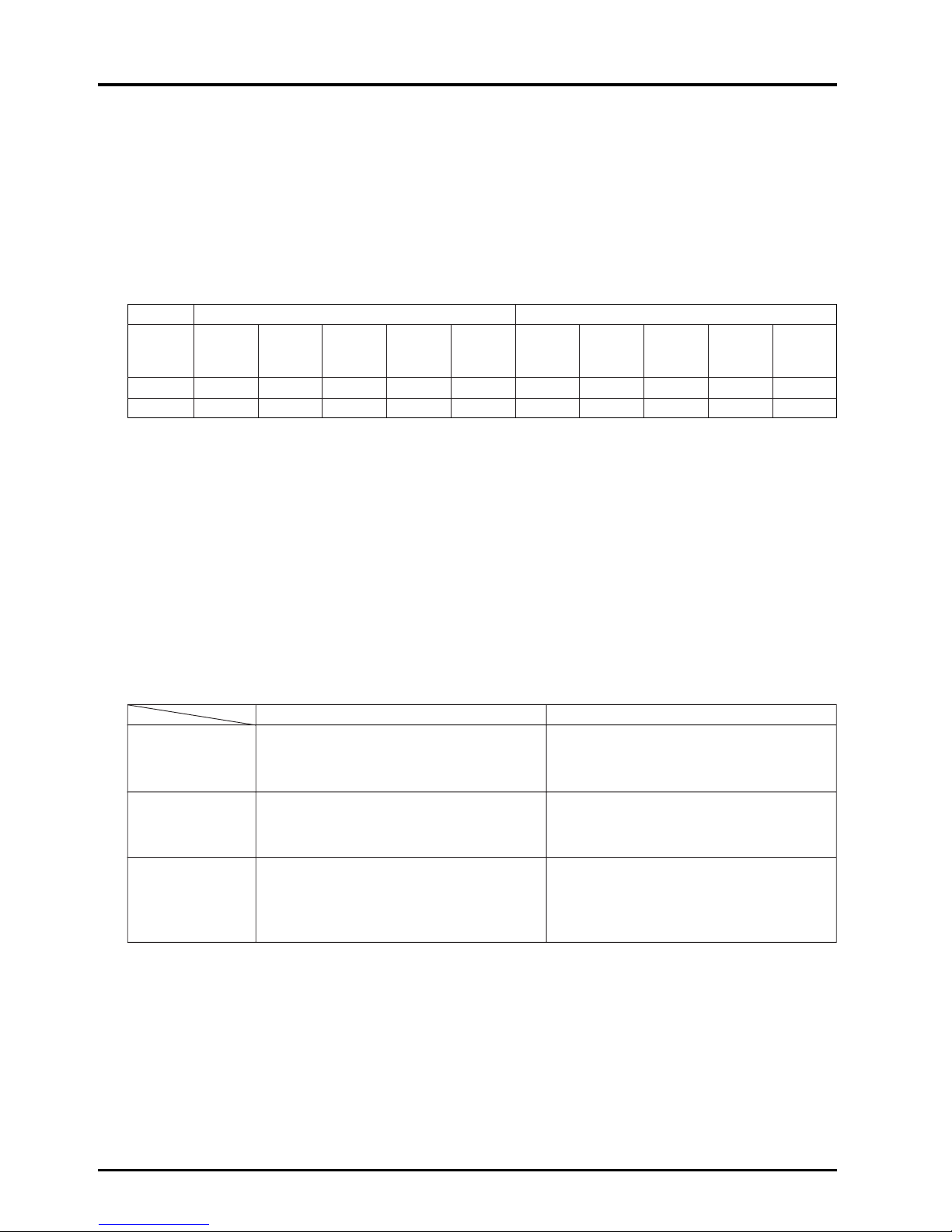
The following table gives a specific account of buildings in Tokyo.
(Tokyo Food and Environment Guidance Center Report)
Specific Account of Buildings in Tokyo (March, 1993)
Number of buildings %
Offices 2,346 65.4
Shops 344 9.6
Department Stores 73 2.0
Schools 388 10.8
Inns 164 4.6
Theaters 84 2.3
Libraries 30 0.8
Museums 15 0.4
Assembly Halls 95 2.6
Art Museums 7 0.2
Amusement Centers 42 1.2
Total 3,588 100.0
Note: Excludes buildings with an expanded floor space of 3,000 to 5,000 m2in particular areas.
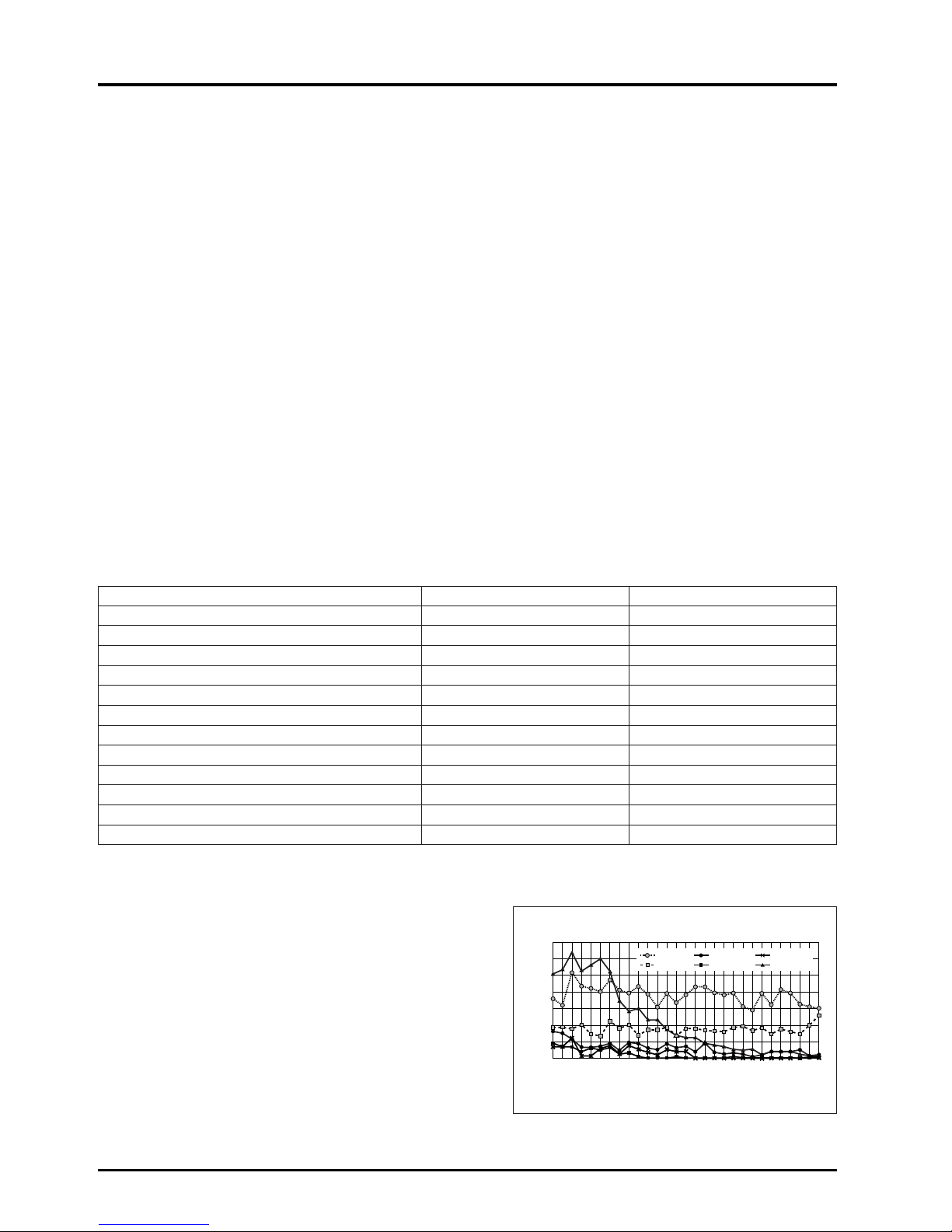
The ratio of results of the air quality measurement public
inspection and the standard values that were not met (percentage
of unsuitability) for the approximately 500 buildings examined in
1980 is shown in the chart at the right.
There was a large decrease in unsuitable percentages of floating
particles, but there was almost no change in temperature and
carbon dioxide. Values for temperature, ventilation, and carbon
monoxide almost entirely cleared the standard values, and are
excluded. The study from 1989 shows the item with the highest
percentage of unsuitability as temperature with 37%, followed by
carbon dioxide at 15%.
76 77 78 79 80 8171 72 73 74 75
82
83 84
85
86
87
88
899091 92 93 94 95 96 97 98 99
70
60
50
40
30
20
10
0
relative humidity
carbon dioxide
temperature
carbon monoxide
ventilation
floating particles
Percentage of unsuitability (%)
Percentage of unsiutability of air quality by year
(according to the Tokyo Food and Environment Guidance Center)
Page 6
3
CHAPTER 1 ● Ventilation for Healthy Living
Effect of carbon monoxide (CO) 10,000 ppm = 1%
Concentration (ppm)
Effect of concentration changes
0.01 - 0.2 Standard atmosphere.
5 Considered to be the long-term tolerable value.
10
The Building Standard Law of Japan, Law for Maintenance of Sanitation in Buildings.
Environmental standard 24-hour average.
20
Considered to be the short-term tolerable value.
Environmental standard 8-hour average.
50
Tolerable concentration for labor environment.
(Japan Industrial Sanitation Association)
100
No effect for 3 hours. Effect noticed after 6 hours.
Headache, illness after 9 hours; harmful for long-term but not fatal.
200 Light headache in the forehead in 2 to 3 hours.
400 Headache in the forehead, nausea in 1 to 2 hours; headache in the back of head in 2.5 to 3 hours.
800 Headache, dizziness, nausea, convulsions in 45 minutes. Comatose in 2 hours.
1,600 Headache, dizziness in 20 minutes. Death in 2 hours.
3,200 Headache, dizziness in 5 to 10 minutes. Death in 30 minutes.
6,400 Death in 10 to 15 minutes.
12,800 Death in 1 to 3 minutes.
Several 10,000 ppm
This level may be found in automobile exhaust.
(Several %)
Apprpx. 5 ppm is
an annual
average value in
city areas.
This value may
exceed 100 ppm
near roads, in
tunnels and
parking areas.
Concentration (%) Standards and effect of concentration changes
Approx. 21 Standard atmosphere.
20.5
Ventilation air volume standard will be a guideline where concentration does not decrease more than 0.5%
from normal value. (The Building Standard Law of Japan)
20 - 19
An oxygen deficiency of this amount does not directly endanger life in a normal air pressure, but if there is a
combustion device in the area, the generation of CO will increase rapidly due to incomplete combustion.
18 Industrial Safety and Health Act. (Hypoxia prevention regulations.)
16 Normal concentration in exhaled air.
16 - 12 Increase in pulse and breathing resulting in dizziness and headaches.
15 Flame in combustion devices will extinguish.
12 Threat to life in short term.
7 Fatal
In the case of Japan, an Instruction Guideline based on these regulations has been issued, and unified guidance is carried out.
Part of the Instruction Guideline regarding ventilation is shown below.
●
The fresh outdoor air intake must be 10 m or higher from ground level, and be distanced appropriately from the exhaust air
outlet. (Neighbouring buildings must also be considered.)
●
The fresh outdoor air intake volume must be 25 to 30 m3/h·person in design.
●
An air volume measurement hole must be installed at an effective position to measure the treated air volume of the
ventilating device.
●
The position and shape of the supply diffuser and return grille must be selected so the air environment in the room is
distributed evenly.
1.2 Effect of air contamination on human bodies
Effect of oxygen (O
2) concentration
Page 7

4
CHAPTER 1 ● Ventilation for Healthy Living
Effect of carbon dioxide (CO2)
Note: According to Facility Check List published by Kagekuni-sha.
1.3 Effect of air contamination in buildings
●
Dirtiness of interior
New ceilings, walls and ornaments will turn yellow in one to two years. This is caused by dust and the tar in tobacco smoke.
2. Ventilation Standards
The legal standards for ventilation differ according to each country. Please follow the standards set by the country. In the US,
Ashrae revised their standards in 1989 becoming more strict.
In Japan, regulations are set in the The Building Standard Law of Japan Enforcement Ordinance, the so-called “Building
Management Law” for securing a sanitary environment in buildings. According to the Building Standards Law, a minimum of
20 m
3
/h per person of ventilation air is required.
Concentration (%) Effect of concentration changes
0.03 (0.04) Standard atmosphere.
0.04 - 0.06 City air.
0.07 Tolerable concentration when many people stay for long time.
0.10
General tolerable concentration.
The Building Standard Law of Japan, Law for Maintenance of Sanitation in Buildings.
0.15 Tolerable concentration used for ventilation calculations.
0.2 - 0.5 Observed as relatively poor.
0.5 or more Observed as the poorest.
0.5 Long-term safety limits (U.S. Labor Sanitation) ACGIH, regulation of laborer offices.
2 Depth of breathing and inhalation volume increases 30%.
3 Work and physical functions deteriorate, breathing doubles.
4 Normal exhalation concentration.
4 - 5
The respiratory center is stimulated; depth and times of breathing increases. Dangerous if breathed in for a
long period. If an O
2 deficiency also occurs, trouble will occur sooner and be more dangerous.
8
When breathed in for 10 minutes, breathing difficulties, redness in the face and headaches will occur.
The trouble will worsen when there is also a deficiency of O
2.
18 or more Fatal
There is no toxic level in
CO2 alone.
However, these tolerable
concentrations are a
guideline of the
contamination estimated
when the physical and
chemical properties of
the air deteriorate in
proportion to the
increase of CO2
.
Page 8
5
CHAPTER 1 ● Ventilation for Healthy Living
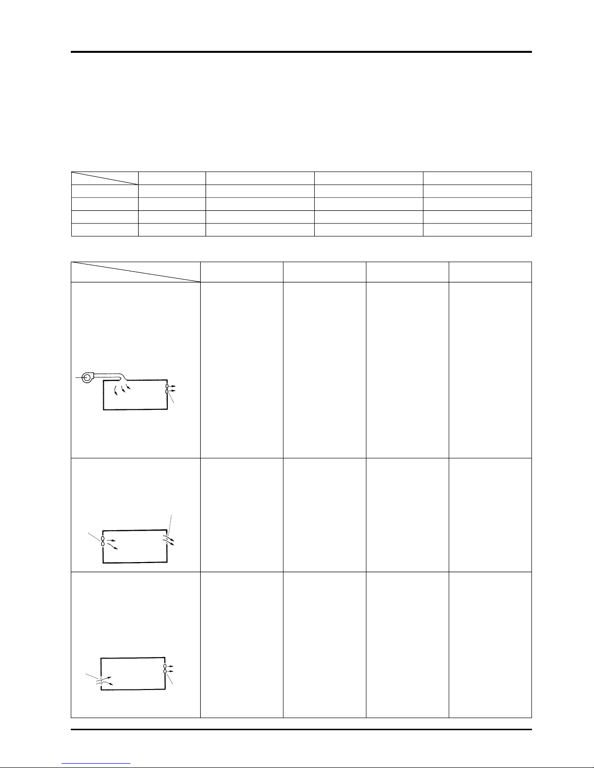
3. Ventilation Method
3.1 Ventilation class and selection points
An appropriate ventilation method must be selected according to the purpose.
Ventilation is composed of “Supply air” and “Exhaust air” functions. These functions are classified according to natural flow or
mechanical ventilation using a fan (forced ventilation).
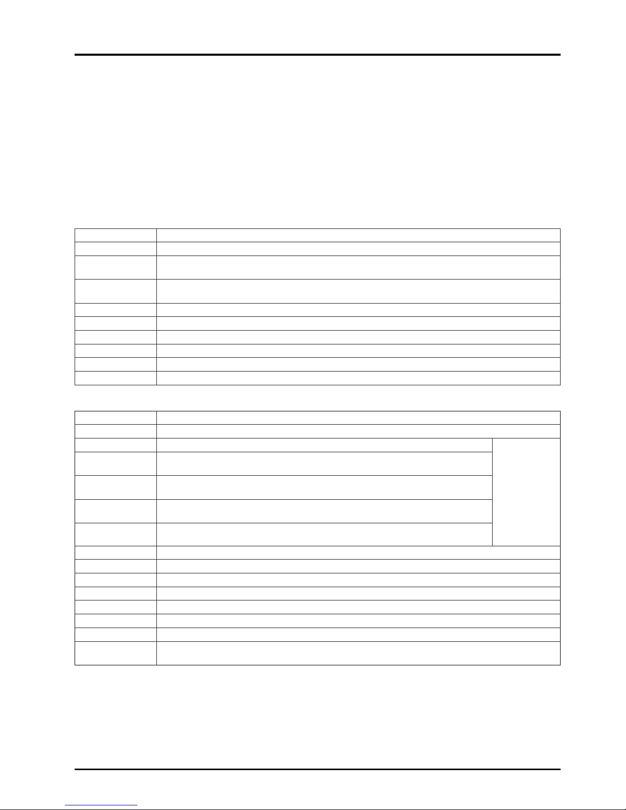
Classification of mechanical ventilation
Classification of ventilation (according to Building Standards Law)
1. Class 1 ventilation
Fresh outdoor air is mechanically
brought in and simultaneously the
stale air in the room is mechanically
discharged.
2. Class 2 ventilation
Fresh outdoor air is mechanically
brought in and the exhaust air is
discharged from the exhaust air
outlet (natural).
3. Class 3 ventilation
The stale air in the room is
mechanically discharged and
simultaneously fresh outdoor air is
mechanically introduced from the
supply air diffuser (natural).
Ex. of application
• Ventilation of air
conditioned rooms.
(buildings, hospitals,
etc.)
• Ventilation of room
not facing an outer
wall. (basement,
etc.)
• Ventilation of large
room. (office, large
conference room,
hall, etc.)
• Surgery theatre.
• Clean rooms.
• Foodstuff processing
factories.
• Local ventilation in
kitchens.
• Ventilation of hot
exhaust air from
machine room, etc.
• Ventilation of humid
exhaust air from
indoor pools, bathrooms, etc.
• General simple
ventilation.
System effect
By changing the
balance of the supply
fan and exhaust fan’s
air volumes, the
pressure in the room
can be balanced
freely, and the
interrelation with
neighboring spaces
can be set freely.
As the room is
pressurized, the flow
of odors and dust,
etc., from neighboring
areas can be
prevented.
The exhaust air is
removed from a local
position in the room,
and dispersion of the
stale air can be
prevented by applying
an entire negative
pressure.
Design and construction
properties
•
An ideal design in which
the supply air diffuser
and exhaust air outlet
position relation and air
volume, etc., can be set
freely is possible.
• A system which adjusts
the temperature and
humidity of the supply
air diffuser flow to the
room environment can
be incorporated.
•
The supply and
exhaust volume can be
set freely according to
the changes in
conditions.
• The position and
shape of the supply
air diffuser can be
set.
• The temperature and
humidity of the
supply air diffuser
flow can be set
accordingly, and
dust can be removed
as required.
• Effective exhausting
of dispersed stale air
generation sites is
possible from a local
exhaust air outlet.
• Ventilation in which
the air flow is not felt
is possible with the
supply air diffuser
setting method.
Selection points
• Accurate supply air
diffuser can be
maintained.
• The room pressure
balance can be
maintained.
• The supply air
diffuser temperature
and humidity can be
adjusted and dust
treatment is
possible.
• The pressure is
positive.
•
The supply air diffuser
temperature and
humidity can be
adjusted, and dust
treatment is possible.
•
The positional relation
of the exhaust air
outlet to the supply air
diffuser is important.
• The room pressure
is negative.
• Local exhaust is
possible.
• Ventilation without
dispersing stale air is
possible.
• Ventilation with
reduced air flow is
possible.
•
The positional relation
of the exhaust air
outlet to the supply air
diffuser is important.
Supply
air
diffuser
Exhaust
fan
Exhaust
air
outlet
Exhaust
fan
Exhaust
fan
Stale
air
Fresh
outdoor
air
Supply Exhaust Ventilation volume Room pressure
Class 1 Mechanical Mechanical Random (constant) Random
Class 2 Mechanical Natural Random (constant) Positive pressure
Class 3 Natural Mechanical Random (constant) Negative pressure
Class 4 Natural Mechanical & natural Limited (inconstant) Negative pressure
Page 9
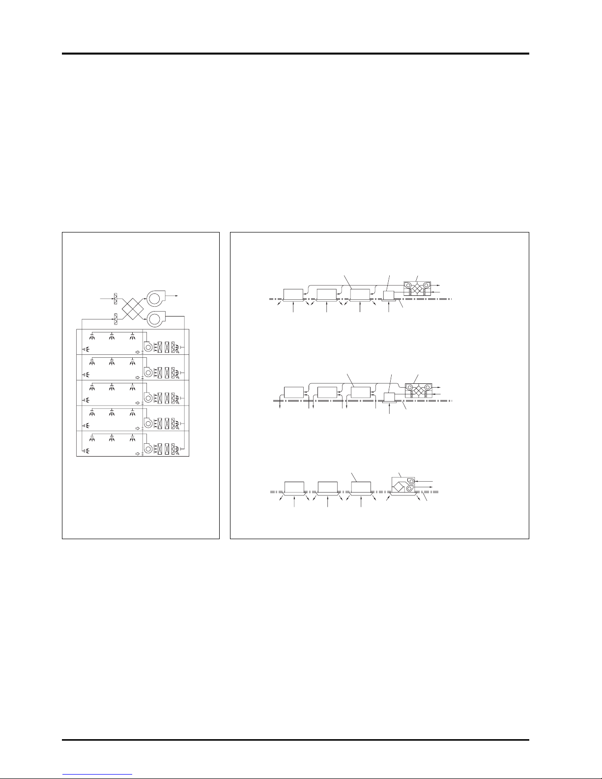
1) System operation with cassette-type air conditioner
2) System operation with ceiling embedded-type air conditioner
3) Independent operation with ceiling suspended-type air conditioner
6
CHAPTER 1 ● Ventilation for Healthy Living
3.2 Comparison of ventilation methods
There are two main types of ventilation methods.
Centralized ventilation method
This is mainly used in large buildings, with the fresh outdoor air intake being installed in one machine room. For this method,
primary treatment of the fresh outdoor air, such as heat recovery to the intake air and dust removal is performed being
distribution to the building by ducts.
Independent zoned ventilation method
This is mainly used in small to medium sized buildings, with areas being ventilated using fresh outdoor air intakes formed of
independent ventilation devices. The rate of use of this method has recently increased as independent control is becoming
ever more feasible.
Centralised ventilation method Independent zoned ventilation method
Air intake
(fresh out-
door air)
Filters
Air exhaust
(stale air)
Cassette-type package air
conditioner or fan coil unit
Cassette-type or ceiling suspended-type
package air conditioner or fan coil unit
Ceiling-mounted type Lossnay or
ceiling embedded-type Lossnay
Exhaust grill
Ceiling recessedtype Lossnay
Exhaust air
Fresh outdoor air
Finished ceiling
Fresh outdoor air
Exhaust air
Finished ceiling
Lossnay
Supply fan
Exhaust
Each unit
Ceiling embedded-type package
air conditioner or fan coil unit
Ceiling recessedtype Lossnay
Exhaust grill
Exhaust air
Fresh outdoor air
Finished ceiling
Page 10

7
CHAPTER 1 ● Ventilation for Healthy Living
Comparison of centralised ventilation method and independent zoned ventilation method
Centralized ventilation method
The air transfer distance is long thus requiring
much fan power.
• Independent equipment room is required.
• Duct space is required.
• Penetration of floors with vertical shaft is not
desired in terms of fire prevention.
Generalized per system.
• Design of outer wall is not lost.
• The indoor supply air diffuser and return grille
can be selected freely for an appropriate design.
As there are many common-use areas, if the
building is a tenant building, an accurate
assessment of operating cost is difficult.
• As the usage time setting and ventilation volume
control, etc., is performed in a central monitoring
room, the user’s needs may not be met
appropriately.
• A large amount of ventilation is required even for
a few persons.
• An ideal supply air diffuser and return grille
position can be selected as the supply air
diffuser and return grilles can be laid out freely.
• The only noise in the room is the aerodynamic
sound.
• Anti-vibration measures must be taken as the
fan in the equipment room is large.
• Centralized management is easy as it can be
performed in the equipment room.
• The equipment can be inspected at any time.
• Large as the entire system is affected.
• Immediate inspection can be performed in the
equipment room.
Fan power
Installation space
Zoning
Designability
Clarification of costs
Controllability
Comfort
Maintenance and
management
Trouble correspondence
Independent zoned ventilation method
As the air transfer distance is short, the fan power
is small.
• Independent equipment room is not required.
• Piping space is required only above the ceiling.
Can be utilised for any one area.
• The number of intakes and exhaust air outlets
on the outer wall will increase; design must be
considered.
• The design will be fixed due to the installation
fittings, so the design of the intakes and exhaust
air outlets must be considered.
Invoicing for each zone separately is possible,
even in a tenant building.
• The user in each zone can operate the ventilator
freely.
• The ventilator can be operated even during offpeak hours.
• Consideration must be made of the noise from
the main unit.
• Anti-vibration measures are often not required
as the unit is compact and the vibration
generated can be dispersed.
• Work efficiency is poor as the equipment is not
centrally located.
• An individual unit can be inspected only when
the room it serves is vacant.
• Limited as only independent units are affected.
• Consultation with the tenant is required prior to
inspection of an individual unit.
Page 11

8
CHAPTER 1 ● Ventilation for Healthy Living
4. Ventilation Performance
The ventilation performance is largely affected by the installation conditions. Ample performance may not be achieved unless
the model and usage methods are selected according to the conditions.
Generally, the ventilation performance is expressed by “Air volume” and “wind pressure (static pressure)”, and these are
necessary when considering ventilation.
4.1 Air volume
Air volume expresses the volume of air exhausted (or supplied) by the unit in a given period. Generally, this is expressed as
m
3
/hr (hour).
4.2 Wind pressure
When a piece of paper is placed in front of a fan and let go, the piece of paper will be blown away. The force that blows the
paper away is called the wind pressure, and this is normally expressed in units of mmH2O or mmAq {Pa (Pascal) in SI unit
system: 1 mmH2O = approx. 9.8Pa}. The wind pressure is divided into the following three types:
4.2.1 Static pressure
This is the force that presses the surroundings when the air is still such as in an automobile tyre or rubber balloon. For
example, in a water gun, the hydraulic pressure increases when pressed by a piston, and if there is a small hole, the water
sprays out with force. The pressure of this water is equivalent to the static pressure for air. The higher the pressure is, the
further the water (air) can be sprayed.
4.2.2 Dynamic pressure
This expresses the speed at which air flows, and can be thought of as the force at which a typhoon presses against a building.
4.2.3 Total pressure
This is the total force that wind has, and is the sum of the static pressure and dynamic pressure.
Page 12
9
CHAPTER 1 ● Ventilation for Healthy Living
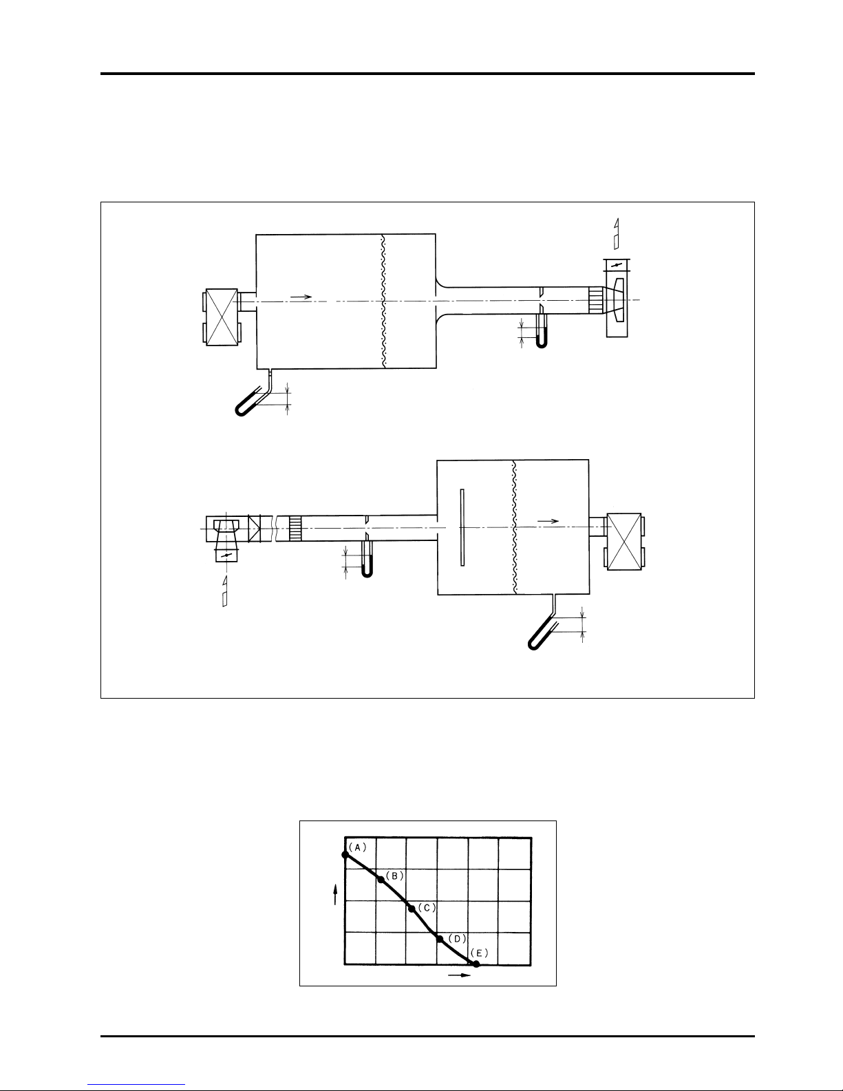
4.3 Measurement of the air volume and wind pressure
Mitsubishi measures the machine’s air volume and wind pressure with a device as shown below according to the Japan
Industrial Standards (JIS B 8628).
Measuring device using orifice (JIS B 8628 standards)
Static pressure (
H
)
Air volume (Q)
Measurement method
The unit is operated with the throttle device fully closed. There is no air flow at this time, and the air volume is 0. The maximum
point of the static pressure (A point, the static pressure at this point is called the totally closed pressure) can be obtained. Next,
the throttle device is gradually opened, the auxiliary fan is operated, and the middle points (points B, C and D) are obtained.
Finally, the throttle device is completely opened, and the auxiliary fan is operated until the static pressure in the chamber
reaches 0. The maximum point of the air volume (point E, the air volume at this point is called the fully opened air volume) is
obtained. The points are connected as shown below, and are expressed as air volume, static pressure curves (Q-H curve).
Connection
Wind dispersing place
Connection
Rectifying
grid
Rectifying
grid
Supply
Air
(SA)
Chamber
Return
Air
(RA)
Rectifying
net
Rectifying
net
Wind gauge
duct path
Orifice
Wind gauge
duct path
Orifice
Damper
Blower
Blower
Test unit
Test unit
Static pressure in chamber
(Static pressure measurement)
Static pressure in chamber
(Static pressure measurement)
Pressure
difference before
and after orifice
(Air volume
measurement)
A) When measuring the supply air volume (with the orifice plate)
B) When measuring the return air volume (with the orifice plate)
Page 13
10
CHAPTER 1 ● Ventilation for Healthy Living
5. Outdoor Air (ventilation) Load
5.1 How to calculate each approximate load
The outdoor air load can be calculated with the following formula if the required outside air intake volume Q m3/h to be
introduced is known:
(Outdoor air load) = γ · QF · (iO - iR)
= γ [kg/m
3
] × S[m2] × k × n [person/m2] × Vf [m3/h·person] × (iO
- iR): ∆i [kJ/kg (kcal/kg)]
γ : Specific gravity of air - 1.2 kg/m
3
S : Building’s airconditioned area
k : Thermal coefficient; generally 0.7 - 0.8.
n : The average population concentration is the inverse of the occupancy area per person. If the number of persons in the
room is unclear, refer to the Floor space per person table below.
Vf : Outdoor air intake volume per person
Refer to the Required outdoor air intake volume per person table below.
iO : Outdoor air enthalpy - kJ/kg (kcal/kg’)
iR : Indoor enthalpy - kJ/kg (kcal/kg’)
Floor space per person table (m
2
)
(According to the Japan Federation of Architects and Building Engineers Associations)
Required outdoor air intake volume per person table (m
3
/h·person)
Caution
The application of this table to each type of room should be carefully considered in relation to the degree of smoking in
the room.
Office building
Department store, shop
Restaurant
Teatre or
Average Crowded Empty
cinema hall
General design 4 - 7 0.5 - 2 0.5 - 2 5 - 8 1 - 2 0.4 - 0.6
value
5 3.0 1.0 6.0 1.5 0.5
Application example
Required ventilation volume
Degree of smoking
Recommended value Minimum value
Broker’s office
Extremely heavy Newspaper editing room 85 51
Conference room
Quite heavy
Bar
51 42.5
Cabaret
Heavy
Office
25.5
17
Restaurant 20
Light
Shop
25.5 17
Department store
None
Theatre 25.5 17
Hospital room 34 25.5
Page 14
Cooling load per unit area
When the volume of outdoor air per person is 25 m
3
/h, and the number of persons per 1 m2is 0.2, the cooling load will be
approximately 157.0 W/m
2
(135 kcal/h·m2).
How these values are determined can be seen as follows:
● Outdoor air load
Air conditions <Standard design air conditions in Tokyo>
11
CHAPTER 1 ● Ventilation for Healthy Living
Example calculations of determining ventilation load during both cooling and heating are given as follows:
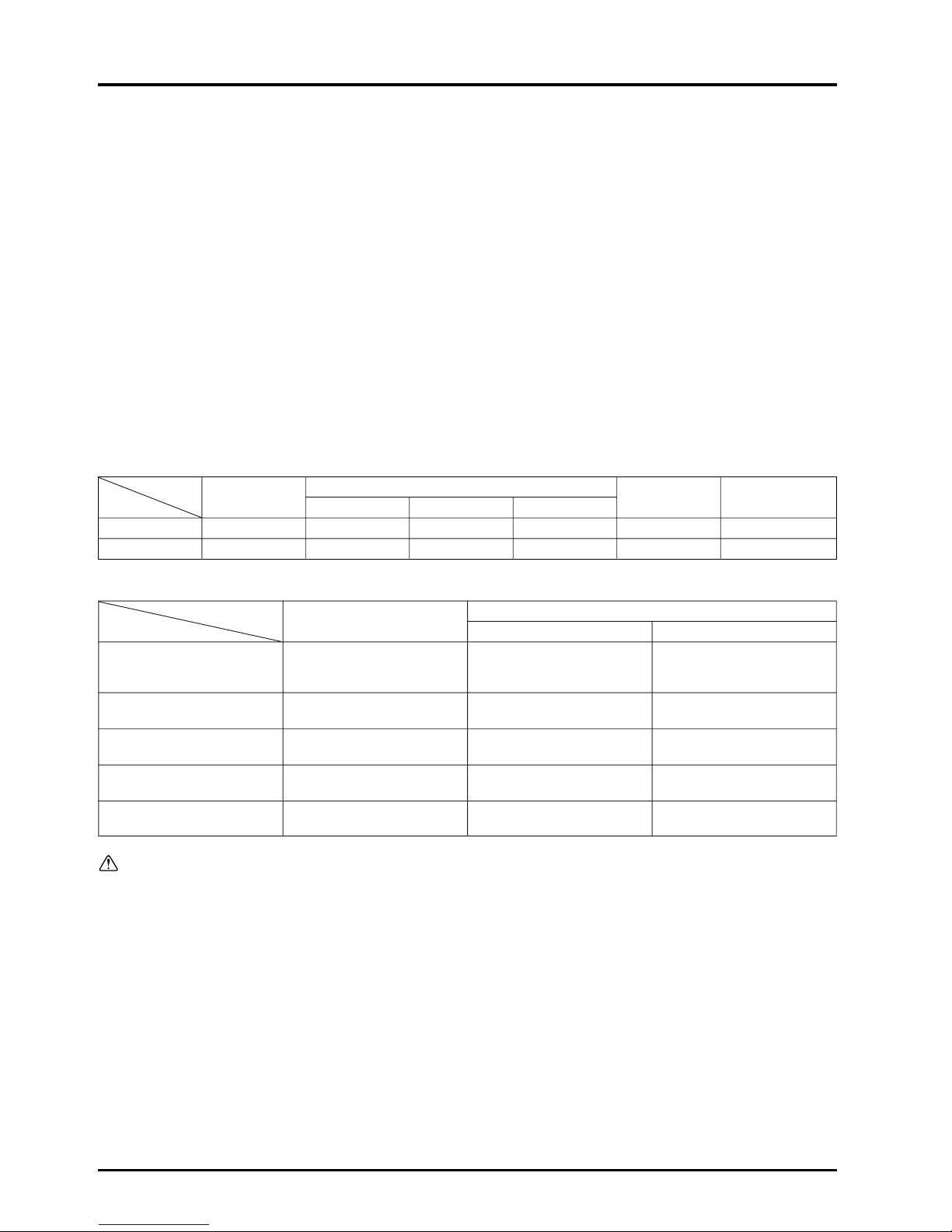
5.2 Ventilation load during cooling (in general office building)
● Classification of cooling load
(a) is the heat infiltrating the room, and often is 30 to 40% of the entire cooling load.
(b) is the heat generated in the room.
(c) is applies only when reheating is necessary.
(d) is the heat generated when outdoor air is mixed into part of the supply air diffuser volume and introduced into the room.
The outdoor air is introduced to provide ventilation for the people in the room, and is referred to as the ventilating load.
Typical load values (during cooling)
Type of load Load
Outdoor air load 53.0 W/m
2
(45.6 kcal/h·m2)
Indoor
People 26.4 W/m
2
(22.7 kcal/h·m2)
generated heat
Lighting equipment 30.0 W/m
2
(25.8 kcal/h·m2)
Indoor infiltration heat 47.6 W/m
2
(40.9 kcal/h·m2)
Total 157.0 W/m
2
(135.0 kcal/h·m2)
Conditions: Middle floor of a general office building facing south.
Class
Heat from walls (q
WS)
(a) Indoor infiltration heat Heat from glass
from direct sunlight (qGS)
from conduction & convection (q
GS)
Accumulated heat load in walls (q
SS
)
Generated heat from people
Sensible heat (q
HS)
(b) Indoor generated heat
Latent heat (q
HL)
Genarated heat from electrical equipment Sensible heat (q
ES)
Latent heat (q
EL)
(c) Reheating load (q
RL)
(d) Outdoor air load
Sensible heat (q
FS)
Latent heat (qFL)
}
}
}
}
Dry bulb temp.
Relative humidity
Wet bulb temp. Enthalpy Enthalpy difference
Cooling
Outdoor air 33 °C 63% 27 °C 85 kJ/kg (20.3 kcal/kg’)
31.8 kJ/kg
Indoors 26 °C 50% 18.7 °C 53.2 kJ/kg (12.7 kcal/kg’)
(7.6 kcal/kg’)
When the load per floor area of 1 m2with a ventilation volume of 25 m3/h·person is calculated with the above air conditions, the
following is obtained:
Outdoor air (ventilation) load = 1.2 kg/m
3
(Specific gravity of air) × 0.2 persons/m2(no. of persons per 1 m2)
× 25 m
3
/h·person (outdoor air volume) × 31.8 kJ/kg (7.6 kcal/kg’) (air enthalpy difference indoors/outdoors)
= 190.8 kJ/h·m
2
(530 W/m2)
The Lossnay recuperates approximately 70% of the exhaust air load and saves on approximately 20% of the total load.
Outdoor air
load 33.8%
53.0 W/m
2
(45.6 kcal/h·m2)
Indoor
infiltration
heat 30.3%
47.6 W/m
2
(41.8 kcal/h·m2)
Indoor
generated heat
(people, lighting
equipment) 35.9%
56.4 W/m
2
156.5 W/m
2
(135.0 kcal/h·m2)
Page 15

12
CHAPTER 1 ● Ventilation for Healthy Living
● Determining internal heat gain
When classifying loads, the internal heat gain (indoor generated heat + indoor infiltration heat) will be the value of the outdoor
air load subtracted from the approximate cooling load when it is assumed that there is no reheating load.
(Internal heat gain)
= 157.0 W/m
2
(135 kcal/h·m2) – 53.0 W/m2(45.6 kcal/h·m2) = 104.0 W/m2(89.4 kcal/h·m2)
●
This value of internal heat gain is based on assumptions for typical loads. To determine individual levels of internal heat
gain, the following is suggested:
● Indoor generated heat
(1) Heat generated from people
Heat generation design value per person in office
Sensible heat (SH)= 63.0 W·person (54 kcal/h·person)
Latent heat (LH) = 69.0 W·person (59 kcal/h·person)
Total heat (TH) = 132.0 W·person (113 kcal/h·person)
The heat generated per 1 m
2
of floor space is
(heat generated from people)
= 132.0 W·person (113 kcal/h·person) × 0.2 person/m
2
= 26.4 W/m2(22.6 kcal/h·m2)
(2) Heat generated from electrical equipment (lighting)
The approximate value of the room illuminance and power for lighting for a general office with illuminance of 300 350 Lux, is 20 - 30 W/m
2
.
● Indoor infiltration heat
This is the heat that infiltrates into the building from outside. This can be determined by subtracting the amount of heat
generated by people and lighting from the internal heat gain.
(Indoor infiltration heat)
= 104.0 – (26.4 + 30.0) = 47.6 W/m
2
(40.9 kcal/h·m2)
The Lossnay recuperates approximately 70% of the outdoor air load and saves on approximately 20% of the total load.
Page 16
13
CHAPTER 1 ● Ventilation for Healthy Living
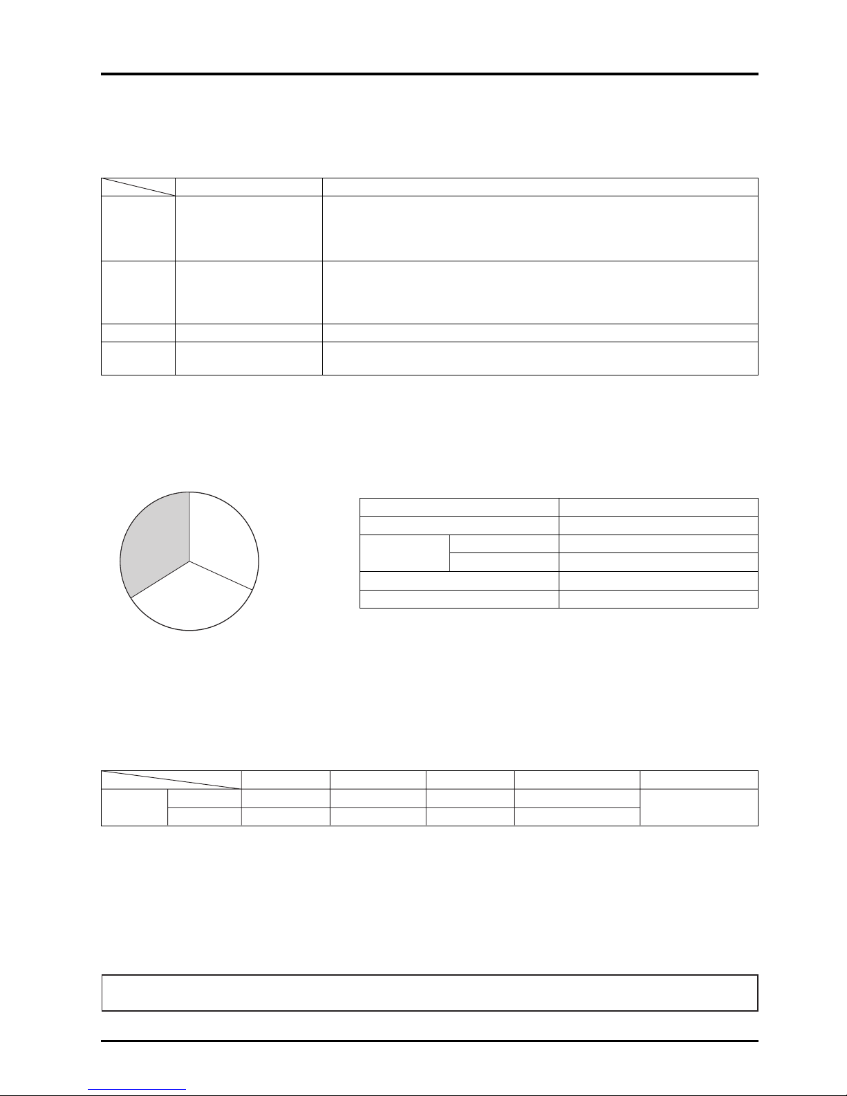
5.3 Ventilation load during heating
●
Classification of heating load
Class
Heat lost from walls (q
WS)
(a)
Indoor heat
Heat lost from glass (q
GS)
loss
Heat loss from conduction & convection (q
GS)
Accumulated heat load in walls (q
SS)
(b)
Outdoor air
Sensible heat (q
FS)
load
Latent heat (q
FL)
During heating, the heat generated by people and electrical equipment in the room can be subtracted from the heating load.
However, as the warming up time at the start of heating is short, this generated heat may be ignored in some cases.
Percentage of load
Internal heat loss
In terms of load classification, the internal heat loss is the value of the outdoor air load subtracted from the approximate
heating load.
Internal heat loss = 133.7 W/m
2
(115.0 kcal/h·m2) – 56.0 W/m2(48.2 kcal/h·m2) = 77.7 W/m2(66.8 kcal/h·m2)
Heating load per unit area
When the outdoor air volume per person is 25 m
3
/h, and the number of persons per 1 m2is 0.2 persons, the approximate
heating load will be approximately 133.7 W/m
2
(115 kcal/h·m2).
●
Outdoor air load
Air conditions <Standard design air conditions in Tokyo>
Type of load Load
Outdoor air load 56.0 W/m
2
(48.2 kcal/h·m2)
Internal heat 77.7 W/m
2
(66.8 kcal/h·m2)
Total 133.7 W/m
2
(115.0 kcal/h·m2)
Conditions: Middle floor of a general office building facing south.
Dry bulb temp.
Relative humidity
Wet bulb temp. Enthalpy Enthalpy difference
Heating
Outdoor air 0 °C 50% –3 °C 5.0 kJ/kg (1.2 kcal/kg’)
33.5 kJ/kg
Indoors 20 °C 50% 13.7 °C 38.5 kJ/kg (9.2 kcal/kg’)
(8.0 kcal/kg’)
When the load per 1 m2of floor area with a ventilation volume of 25 m3/h·person is calculated with the above air conditions, the
following is obtained:
Outdoor air (ventilation) load = 1.2 kg/m
3
× 0.2 persons/m2× 25 m3/h·person × 33.5 kJ/kg (8.0 kcal/kg’)
= 201.0 kJ/h·m
2
(56 W/m2)
The Lossnay recuperates approximately 70% of the outdoor air load and saves on approximately 30% of the total load.
Outdoor
air load 41.9%
56.0 W/m
2
(48.0 kcal/h·m2)
Indoor heat
loss 58.1%
77.7 W/m
2
(67.0 kcal/h·m2)
133.7 W/m
2
(115.0 kcal/h·m2)
Page 17

Page 18

CHAPTER 2
Lossnay Construction and Principle
Page 19
16
CHAPTER 2 ● Lossnay Construction and Principle
1. Construction and Features of Lossnay
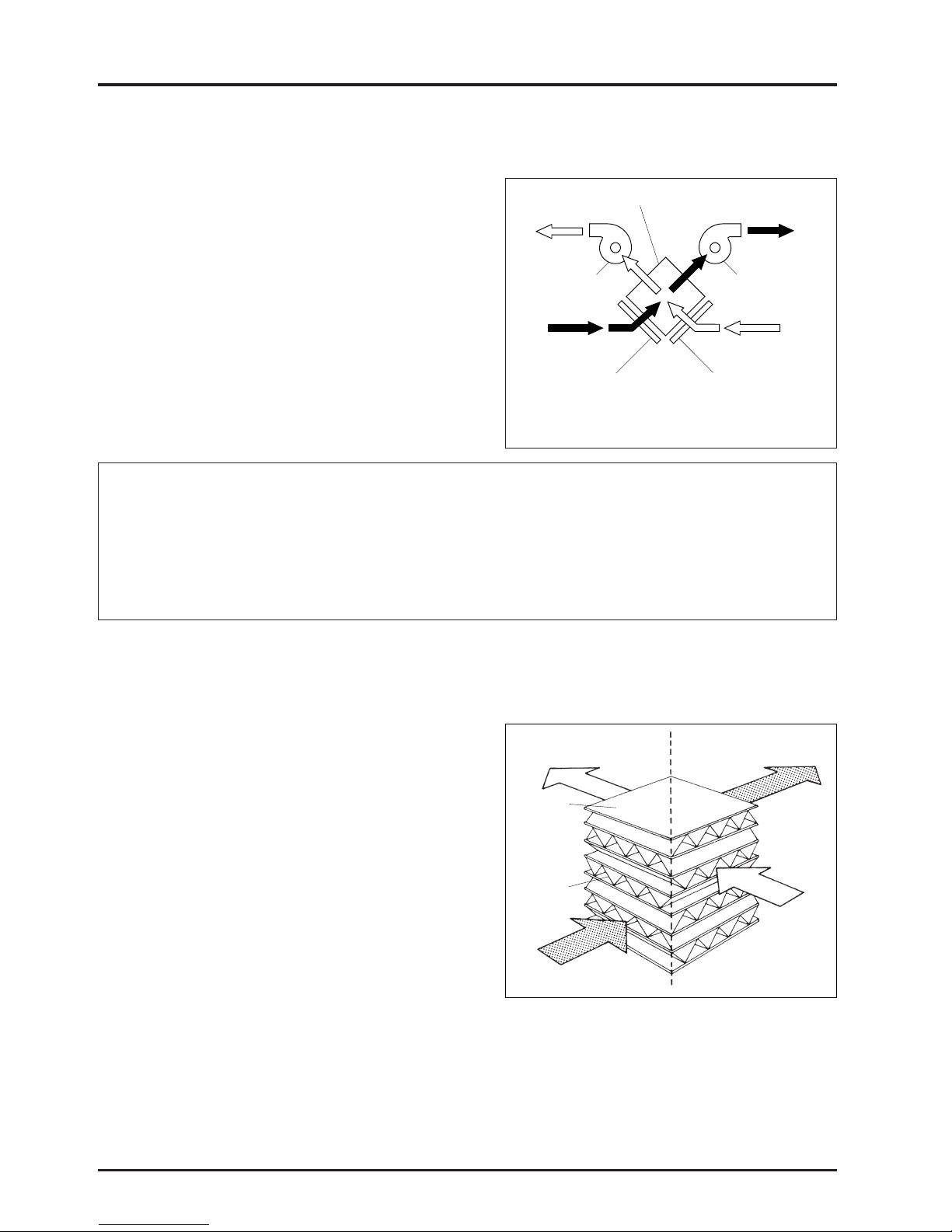
● Lossnay construction
The Lossnay is constructed so that the exhaust air passage from
the indoor side to the outdoor side (RA → EA) and the fresh air
passage from the outdoor side to the indoor side (OA → SA)
cross. The Lossnay heat recovery unit (Lossnay Core) is installed
at this cross point, and recovers the heat by conduction through
the separating medium between these airflows. This enables the
heat loss during exhaust to be greatly reduced.
* RA : Return Air
EA : Exhaust Air
OA : Outdoor Air
SA : Supply Air
SA
(Supply air diffuser)
Supply fan
RA
(Return air)
Exhaust side filter
Lossnay Core
Intake side filter
OA
(Outdoor air)
Exhaust fan
EA
(Exhaust air)
Main Features of Lossnay
(1) Cooling and heating maintenance fees are saved while ventilating.
(2) The capacity and performance of the air conditioner can be reduced.
(3) Dehumidifying during summer, and humidifying during winter is possible.
(4) Comfortable ventilation is possible, (the outdoor air being adjusted to the room temperature.)
(5) Effective sound-proofing.
Note: The dust inlet and outlet are linear in the
actual product.
2. Construction and Principle of Core
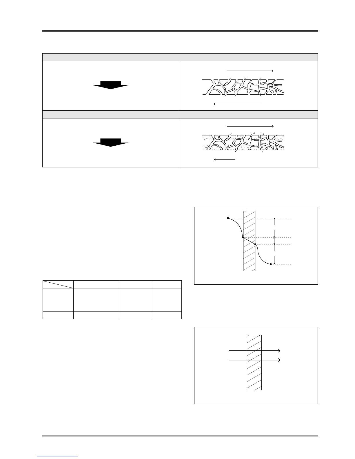
● Simple construction
The Lossnay Core is a cross-flow total heat recovery unit
constructed of plates and fins made of treated paper.
The fresh air and exhaust air passages are totally separated
allowing the fresh air to be introduced without mixing with the
exhaust air.
●
Principle
The Lossnay Core uses the heat transfer properties and moisture
permeability of the treated paper. Total heat (sensible heat plus
latent heat) is transferred from the stale exhaust air to the fresh air
being introduced into the system when they pass through the
Lossnay. Try this simple experiment. Roll a piece of paper into a
tube and blow through it. Your hand holding the paper will
immediately feel warm. If cold air is blown through the tube, your
hand will immediately feel cool. Lossnay is a total heat exchanger
that utilizes these special properties of paper.
●
Treated paper
The paper partition plates are treated with special chemicals so that the Lossnay Core is an appropriate heat recovery unit for
the ventilator. This paper differs from ordinary paper, and has the following unique properties.
(1) The paper is incombustible and is strong.
(2) The paper has selective hydroscopicity and moisture permeability that permits the passage of water vapor only (including
some water-soluble gases).
(3) The paper has gas barrier properties that does not pass gases such as CO
2.
SA
Supply air diffuser
(Fresh cold or warm air)
Partition
plate
(Treated
paper)
Spacer plate
(Treated paper)
RA
Return air
(Stale cold or warm air)
Indoors Outdoors
EA
Exhaust air
(Stale air)
OA
Outdoor air
(Fresh air)
Page 20
17
CHAPTER 2 ● Lossnay Construction and Principle
A comparison of the ordinary paper and the Lossnay Core plates is as shown in the table.
Ordinary paper
Water vapor is transferred, but gas elements that are easily
dissolved in water such as CO
2, NO2 are also transferred.
The contaminated air passes through the plates during
ventilation and returns to the room.
Treated paper
Water vapor is transferred, but gas elements such as CO
2,
NO
2 are not transferred.
The contaminated air does not return to the room when
ventilated.
Highly humid air
Water vapor
Water vapor
CO2 NO2
CO2 NO2
CO2 NO2Water vapor
Water vapor
Treatment
(Selective permeable film)
(Incombustible specifications)
Low humid air
Highly humid air
Cellulose
fibers
Low humid air
● Total heat recovery mechanism
Sensible heat and latent heat
The heat that enters and leaves in accordance with changing temperature (rise or drop) is called sensible heat. The heat that
enters and leaves due to the changes in a matter’s physical properties (evaporation, condensation) is called latent heat.
(1) Temperature (sensible heat) recovery
1) Heat conduction and heat passage is performed through a
partition plate from the high temperature to low temperature
side.
2) As shown on the right, the heat recovery efficiency is affected
by the resistance of the boundary layer, and for the Lossnay
there is little difference when compared to materials such as
copper or aluminium which also have high thermal
conductivity.
Heat resistance coefficients
t1
t2
Ra1
Ra2
Rp
Partition plate
Ra1+Ra2
»Rp
Treated paper Cu Al
Ra
1 10 10 10
Rp 1 0.00036 0.0006
Ra
2 10 10 10
Total 21 20.00036 20.0006
(2) Humidity (latent heat) recovery
●
Water vapor is moved through the partition plate from the
high humidity to low humidity side by means of the
differential pressure in the vapor.
High humidity side
Low humidity side
Partition plate
Page 21
18
CHAPTER 2 ● Lossnay Construction and Principle
3. Calculation of the Total Heat Recovery Efficiency
The Lossnay Core’s heat recovery efficiency can be considered
using the following three transfer rates:
(1) Temperature (sensible heat) recovery efficiency
(2) Humidity (latent heat) recovery efficiency
(3) Enthalpy (total heat) recovery efficiency
The heat recovery effect can be calculated if two of the above
efficiencies is known. (The temperature and enthalpy efficiencies
are indicated in the applicable catalogue.)
●
Each recovery efficiency can be calculated with the formulas
given below.
●
When the supply air volume and exhaust air volume are equal,
the heat recovery efficiencies on the supply and exhaust sides
are the same.
●
When the supply air volume and exhaust air volume are not
equal, the total heat recovery efficiency is low if the exhaust
volume is lower, and high if the exhaust volume is higher.
Refer to the Heat Recovery Efficiency Correction Curve in the
applicable catalogue for more details.
SA
Supply air
(Fresh cold or warm air)
RA
Return air
(Stale cold or warm air)
Indoors Outdoors
EA
Exhaust air
(Stale air)
OA
Outdoor air
(Fresh air)
Item Formula
Temperature recovery
efficiency (%)
ηt =
t (
OA) - t (SA)
× 100
t (
OA) - t (RA)
Enthalpy recovery
efficiency (%)
ηi =
i (
OA) - i (SA
)
× 100
i (
OA) - i (
RA)
η: Efficiency (%)
t : Dry bulb temperature (°C)
i : Enthalpy (kJ/kg) (kcal/kg’)
Calculation of air conditions after passing through Lossnay
If the Lossnay heat recovery efficiency and the conditions of the room and outdoor air are known, the conditions of the air
entering the room and the air exhausted outdoors can be determined with the following formulas.
Supply side Exhaust side
Temperature t
SA = tOA - (tOA - tRA) · ηttEA = tRA + (tOA - tRA) · ηt
Enthalpy i
SA = iOA - (iOA - iRA) · ηiiEA = iRA + (iOA - iRA) · ηi
Page 22
19
CHAPTER 2 ● Lossnay Construction and Principle
4. What is a Psychrometric Chart?
The chart which shows the properties of humid air is called a psychrometric chart. The psychrometric chart can be used to
find the (1) Dry bulb temperature, (2) Wet bulb temperature, (3) Absolute humidity, (4) Relative humidity, (5) Dew point and (6)
Enthalpy (total heat) of a certain air condition. If two of these values are known beforehand, the other values can be found with
this chart. The way that the air will change when it is heated, cooled, humidified or dehumidified can also be seen easily on
the chart.
(1) Dry bulb temperature t (°C)
Generally referred to as standard temperature this is
measured with a dry bulb thermometer (conventional
thermometer). The obtained value is the dry bulb
temperature.
(2) Wet bulb temperature t’ (°C)
When a dry bulb thermometer’s heat sensing section is
wrapped in a piece of wet gauze and an ample air flow
(3 m/s or more) is applied, the heat applied to the wet bulb by
the air and the heat of the water vapor that evaporates from
the wet bulb will balance at an equal state. The temperature
indicated at this time is called the wet bulb temperature.
(3) Absolute humidity x (kg/kg’)
The weight (kg) of the water vapor that corresponds to the
weight (kg’) of the dry air in the humid air is called the
absolute humidity.
(4) Relative humidity ϕ (%)
The ratio of the water vapor pressure Pw in the humid air and
the water vapor pressure Pws in the saturated air at the same
temperature is called the relative humidity. This is obtained
with the following formula:
ϕR = PW/PWS × 100
(5) Dew point t” (°C)
The water content in the air will start to condense when air is
cooled.
The dry bulb temperature at this time is called the dew point.
(6) Enthalpy i (kJ/kg) (kcal/kg’)
Physical matter has a set heat when it is at a certain
temperature and state. This retained heat is called the
enthalpy, with dry air at 0 °C being set at 0.
Temperature (°C)
Absolute humidity x (kg/kg’)
Wet bulb temperature
(dew point) t’ (°C)
Relative humidity ϕ (%)
The dew point t” of the air at point A is the
temperature of the point at the same absolute humidity
as point A on the saturation curve.
t” °C dew point
(kJ/kg)
Enthalpy i (kcal/kg’)
A
t”
Parallel to absolute
temperature scale line
Page 23
20
CHAPTER 2 ● Lossnay Construction and Principle
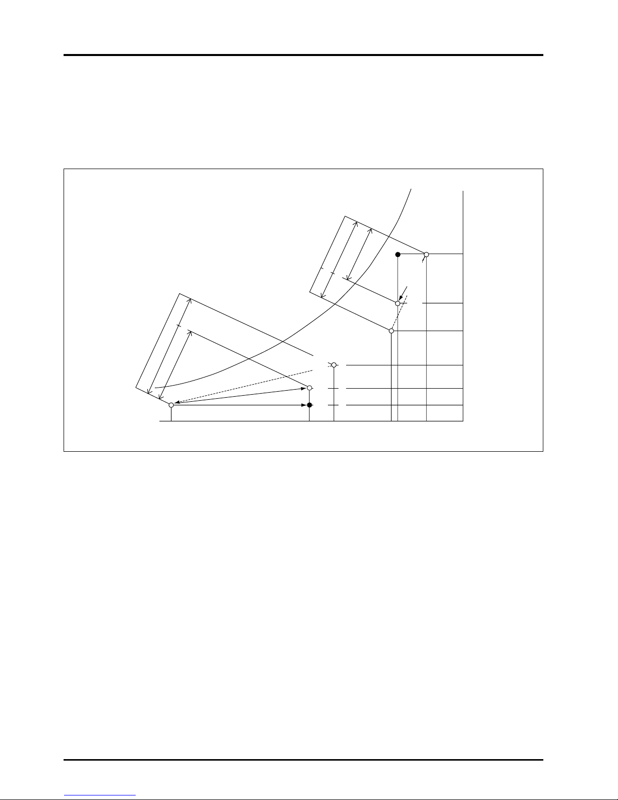
5. Calculation of Lossnay Heat Recovery
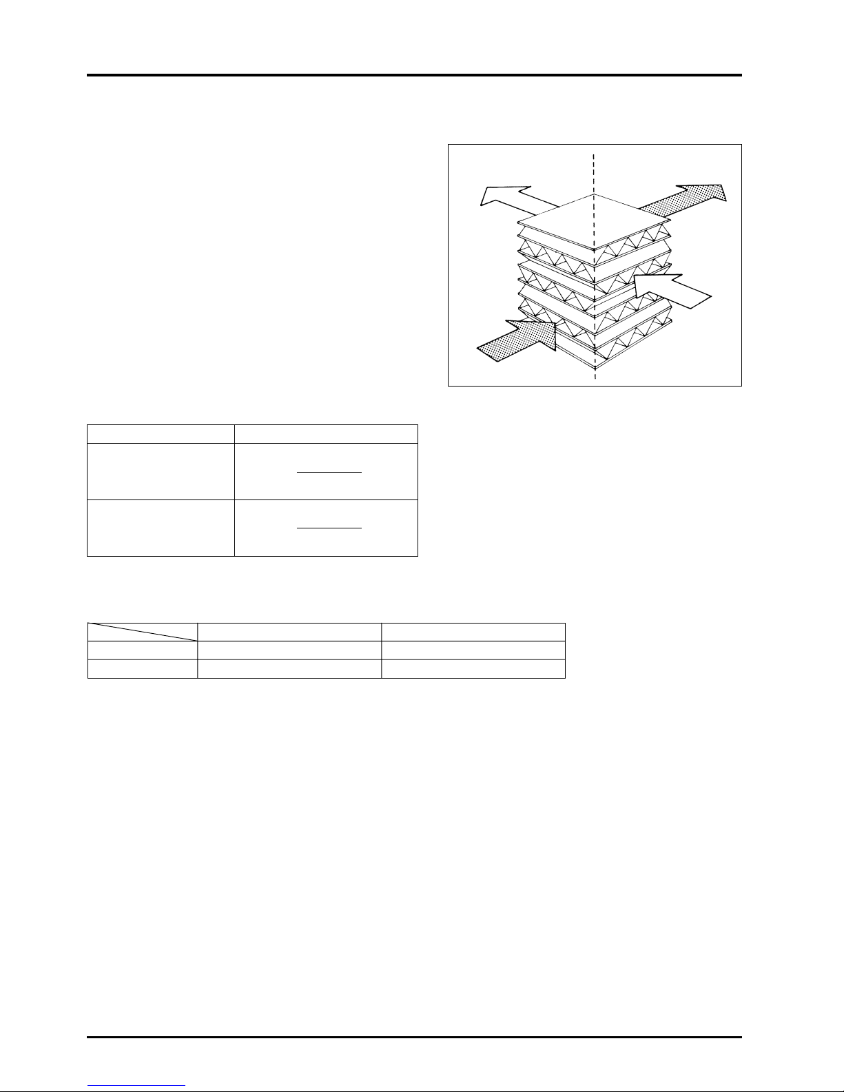
The following figure shows the conditions of various air states when fresh air is introduced through the Lossnay Core. If a
conventional sensible heat recovery unit is used alone and is assumed to have the same heat recovery efficiency as Lossnay,
the condition of the air supplied to the room is expressed by point A in the figure. This point shows that the air is very humid in
summer and very dry in winter.
The air supplied to the room with Lossnay is indicated by point S in the figure. The air is precooled and dehumidified in the
summer and preheated and humidified in the winter before it is introduced to the room.
iSA
iOA
tOA tSA
A
S
O
R
i
RA
iSA
iOA
tRA tRA
S
R
AO
t
SA tOA
XOA
XSA
XRA
XRA
XSA
XOA
iRA
The quantity of heat recovered by using the Lossnay Core can be calculated with the following formula.
Total heat recovered: q
T = γ · Q · (iOA - iSA) [W (kcal/h)]
= γ · Q · (i
OA
- i
RA) ×ηi
Where γ = Specific weight of air under standard conditions 1.2 (kg/m
3
)
Q = Treated air volume (m
3
/h)
t = Temperature (°C)
x = Absolute humidity (kg/kg’)
i = Enthalpy (kJ/kg) (kcal/kg’)
η = Heat recovery efficiency (%)
●
Suffix meanings
OA : Outdoor air
RA : Return air
SA : Supply air
Enthalpy
(kJ/kg) (kcal/kg
’)
Outdoor air load
Lossnay Core heat recovery
Enthalpy
(kJ/kg) (kcal/kg
’)
Outdoor air load
Lossnay Core heat recovery
Outdoor air
condition in
winter
Supply air condition of
the Lossnay
Supply air condition of
the Lossnay
Room air
condition
in summer
Outdoor air condition
in summer
Absolute
humidity (kg/kg’)
Room air condition in winter
Dry bulb temperature (°C)
Page 24

CHAPTER 3
General Technical Considerations
Page 25
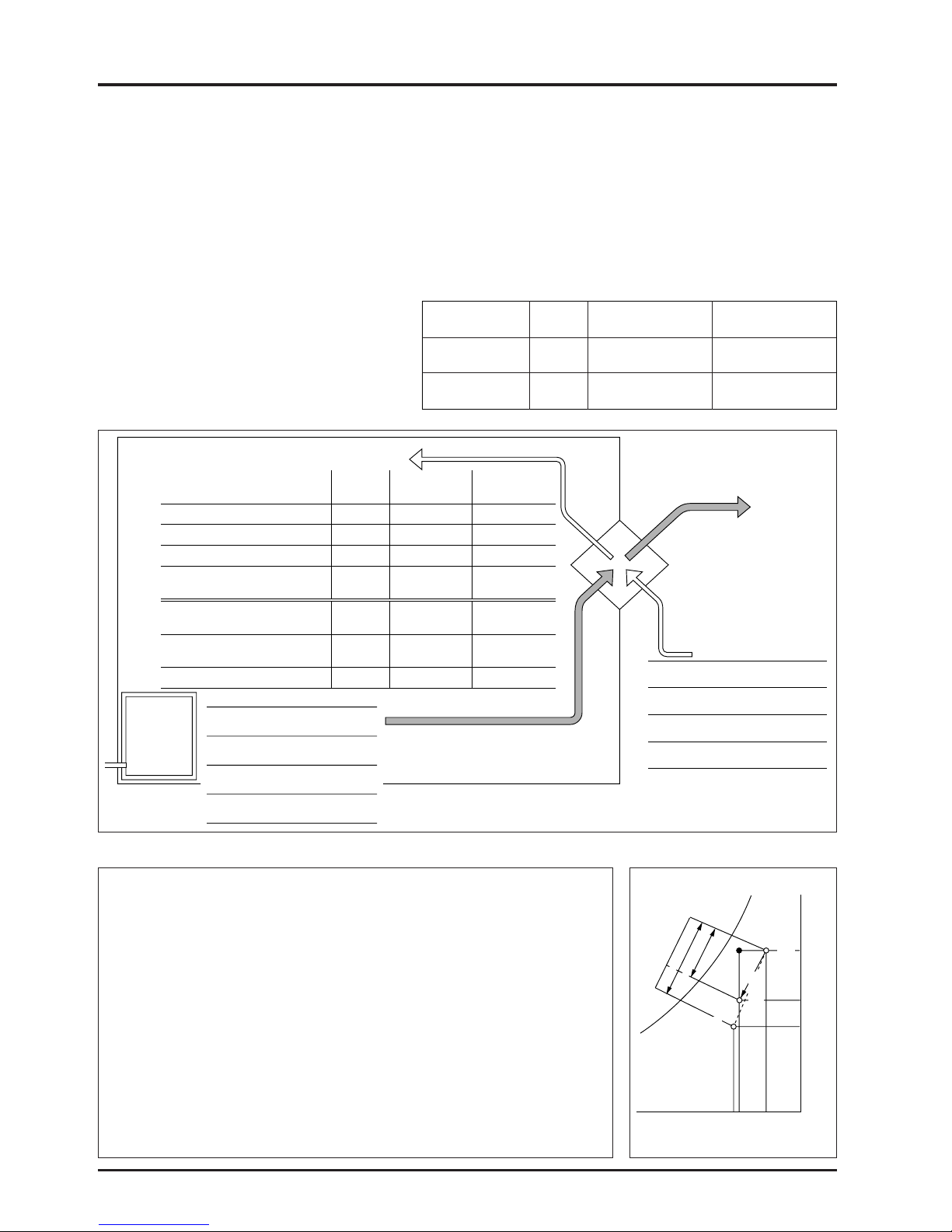
1. Lossnay Heat Recovery Effect
1.1 Comparison of outdoor air load of various ventilators
Examples of formulas to compare the heat recovered and outdoor air load when ventilating with the Lossnay (total heat
recovery unit), sensible heat recovery ventilation (sensible HRV) and conventional ventilators are shown below.
(1) Cooling during summer
Conditions
●
Model LGH-50R type
●
Heat recovery efficiency table (%)
(at 50Hz, high speed) (For summer)
●
Ventilation rate: 500 m3/h
(specific gravity of air
ρ
= 1.2 kg/m3)
22
CHAPTER 3 ● General Technical Considerations
Lossnay Sensible HRV
Conventional
ventilator
Temperature
77 77 –
(sensible heat)
Enthalpy
61.5 18.2* –
(total heat)
hOA
hSA
hRA
85.0
65.4
53.2
tOA
33
tSA
27.6
tRA
26
R
S
AO
X
OA
0.0203
XSA
0.0148
XRA
0.0105
●
Lossnay
(Supply air diffuser temperature)
tSA = 33°C – (33°C – 26°C) × 0.77 = 27.6°C
(Supply air diffuser enthalpy)
hSA = 85.0 – (85.0 – 53.2) × 0.615 = 65.4 kJ/kg
Heat recovered
(85.0 – 65.4) × 1.2 × 500 = 11,760 kJ/h = 3.3 kW (2,809 kcal/h)
Outdoor air load
(65.4 – 53.2) × 1.2 × 500 = 7,320 kJ/h = 2.0 kW (1,749 kcal/h)
●
Sensible HRV
(Supply air diffuser temperature)
tSA = 33°C – (33°C – 26°C) × 0.77 = 27.6°C
(Supply air diffuser enthalpy)
hSA
= 79.2 kJ/kg (18.9 kcal/kg) (from psychrometric chart)
Heat recovered
(85.0 – 79.2) × 1.2 × 500 = 3,480 kJ/kg = 1.0kW (831 kcal/h)
Outdoor air load
(79.2 – 53.2) × 1.2 × 500 = 15,600 kJ/H = 4.3 kW (3,727 kcal/h)
[Calculated enthulpy recovery efficiency 3,480 ÷ (3,480 + 15,600) × 100 = 18.2]
●
Conventional ventilator
If a conventional ventilator is used, the heat recovered will be 0 as the supply air
diffuser is equal to the outdoor air.
The outdoor air load is:
(85.0 – 53.2)
×
1.2 ×500 = 19,080 kJ/h = 5.3 kW (4558 kcal/h)
Calculation example Summer conditions
Absolute humidity (kg/kg’)
Room air condition in summer
Outdoor air condition
in summer
Supply air condition
of the Lossnay
Dry bulb temperature (°C)
L
o
s
sn
a
y h
e
a
t re
c
o
ve
ry
Outdoor air load
Enthalpy
kJ/kg
Supply air
Room air
Air
conditioner
Lossnay Sensible HRV
Conventional
ventilator
Dry bulb
temperature
Absolute
humidity
Relative
humidity
Enthalpy
26°C
27.6 27.6 33
14.8 20.3 20.3
63 86 63
65.4 79.2 85.0
(15.6) (18.9) (20.3)
3.3 1.0
0
(2,809) (831)
2.0 4.3 5.3
(1,749) (3,727) (4,558)
38.5 82 100
10.5 g/kg’
50%
53.2 kJ/kg
(12.7 kcal/kg’)
Outdoor air
Exhaust air
Dry bulb
temperature
Absolute
humidity
Relative
humidity
Enthalpy
33°C
20.3 g/kg’
63%
85.0 kJ/kg
(20.3 kcal/kg’)
Dry bulb temperature (°C)
Absolute humidity (g/kg’)
Relative humidity (%)
Enthalpy
(kJ/kg)
(kcal/kg’)
Outdoor air load
(kW)
(kcal/h)
Outdoor air load ratio (%)
Total heat recovered
(kW)
(kcal/h)
* Calculated volume under below conditions.
Page 26
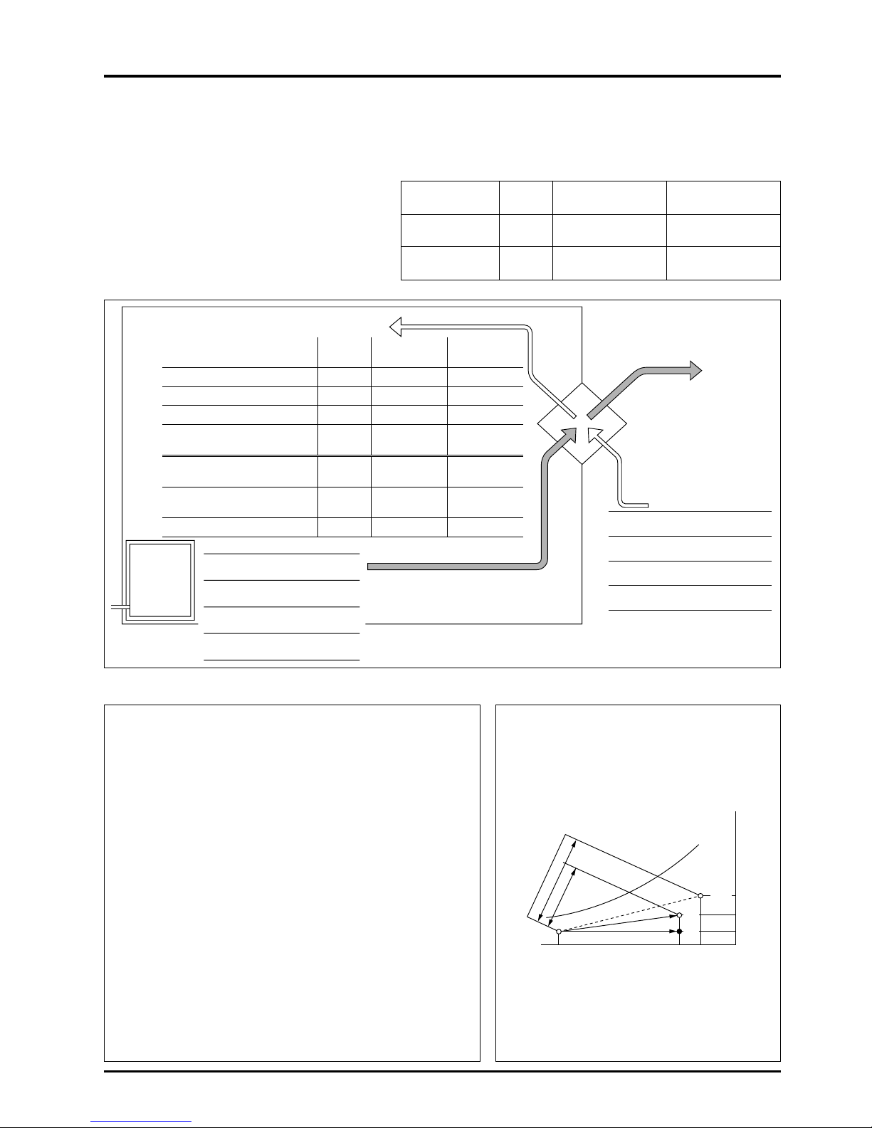
(2) Heating during winter
Conditions:
●
Model LGH-50R type
●
Heat recovery efficiency table (%)
(at 50Hz, high speed) (For winter)
●
Ventilation rate: 500 m3/h
(Specific gravity of air
ρ
= 1.2 kg/m3)
23
CHAPTER 3 ● General Technical Considerations
Lossnay Sensible HRV
Conventional
ventilator
Temperature
77 77 –
(sensible heat)
Enthalpy
67 44.2* –
(total heat)
Supply air
Room air
Air
conditioner
Lossnay Sensible HRV
Conventional
ventilator
Dry bulb
temperature
Absolute
humidity
Relative
humidity
Enthalpy
20°C
15.4 15.4 0
4.6 1.8 1.8
43 17 50
27.4 19.8 5.0
(6.5) (4.7) (1.2)
3.7 2.4
0
(3,211) (2,121)
1.9 3.2 5.6
(1,591) (2,680) (4,802)
33 57 100
7.2 g/kg’
50%
38.5 kJ/kg
(9.2 kcal/kg’)
Outdoor air
Exhaust air
Dry bulb
temperature
Absolute
humidity
Relative
humidity
Enthalpy
0°C
1.8 g/kg’
50%
5.0 kJ/kg
(1.2 kcal/kg’)
Dry bulb temperature (°C)
Absolute humidity (g/kg’)
Relative humidity (%)
Enthalpy
(kJ/kg)
(kcal/kg’)
Outdoor air load
(kW)
(kcal/h)
Outdoor air load ratio (%)
Total heat recovered
(kW)
(kcal/h)
●
Lossnay
(Supply air diffuser temperature) tSA=
(20°C – 0°C) × 0.77 + 0°C = 15.4°C
(Supply air diffuser
enthalpy)
hSA=
(38.5 – 5.0) × 0.67 + 5.0
=
27.4 kJ/kg
Heat recovered (27.4 – 5.0) × 1.2 × 500
= 13,440 kJ/h = 3.7 kW (3,211 kcal/h)
Outdoor air load (38.5 – 27.4) × 1.2 × 500
=
6,660 kJ/h = 1.9 kW (1,591 kcal/h)
●
Sensible HRV
(Supply air diffuser temperature) tSA=
(20°C – 0°C) × 0.77 + 0°C = 15.4°C
(Supply air diffuser
enthalpy)
hSA=
19.8 kJ/kg (4.7 kcal/kg’)
(from psychrometric chart)
Heat recovered (19.8 – 5.0) × 1.2 × 500
= 8,880 kJ/h = 2.5 kW (2,121kcal/h)
Outdoor air load (38.5 – 19.8) × 1.2 × 500
= 11,200 kJ/h = 3.1 kW (2,681 kcal/h)
[Calculated enthulpy recovery efficiency 8,880 ÷ (8,880 + 11,200) × 100 = 44.2]
●
Conventional ventilator
If a conventional ventilator is used, the supply air diffuser is the same
as the outdoor air and the exhaust is the same as the room air.
Thus the heat recovered is 0 kcal and the outdoor air load is
(38.5 – 5.0) × 1.2 × 500 = 20,100 kJ/h = 5.6 kW (4,802 kcal/h)
Calculation example Winter conditions
hRA
iOA
tOA
0
tSA
15.4
tRA
20
R
S
O
A
X
RA 0.0072
XSA 0.0046
XOA 0.0018
hSA
38.5
5.6
27.4
Absolute humidity (kg/kg’)
Outdoor air
condition in
winter
Room air condition
in winter
Supply air condition
of the Lossnay
Dry bulb temperature (°C)
Lossnay
heat recovery
Outdoor air load
Enthalpy
kJ/kg
* Calculated volume under below conditions.
Page 27
24
CHAPTER 3 ● General Technical Considerations
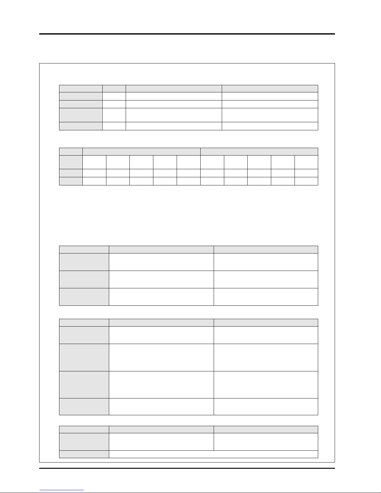
2. Example Heat Recovery Calculation
(1) Setting of conditions
(Note: Tokyo Power, industrial power 6 kV supply)
●
Return air volume (RA) = 7,200 m3/Hr
●
Outdoor air volume (OA) = 8,000 m3/Hr
●
Air volume ratio (RA/OA) = 0.9
●
Air conditions
(2) Selection of Lossnay model (select from treatment air volume catalogue)
●
Model name: LU-160 with combination of LU-1605 × 1 unit
●
Processing air volume per unit RA = 7,200 m3/Hr, OA = 8,000 m3Air volume ratio (RA/OA) = 0.9
●
Heat recovery efficiency : Heat recovery efficiency = 73%, Enthalpy recovery efficiency (cooling) = 62%,
Enthalpy recovery efficiency (heating) = 67%
●
S
tatic pressure loss (unit-type) RA = 156.9 Pa, OA = 186.3 Pa (Note: Each with filters)
●
Power consumption (pack-type) = none because of unit type
(3) State of indoor supply air
(4) Outdoor air load and heat recovered
(5) Recovered money (power rates)
Units When Heating When Cooling
Operation time (h/yr)
10h/day × 26 days/mo. × 5 mo./yr. = 1,300 h/yr 10h/day × 26 days/mo. × 4 mo./yr. = 1,040 h/yr
Electricity fee
(yen/kWh)
16.22 17.84
Capacity per
(kW/kW) 3.1 2.6
1 kW of electricity
Energy unit cost
(yen/kWh)
16.22/3.1 = 5.23 17.84/2.6 = 6.86
Season Winter heating Summer cooling
Item
Dry bulb temp. Wet bulb temp.
Relative humidity Absolute humidity
Enthalpy h Dry bulb temp. Wet bulb temp.
Relative humidity Absolute humidity
Enthalpy h
DB [°C] WB [°C] RH [%] × [kg/kg (DA)] [kJ/kg (DA)] DB [°C] WB [°C] RH [%] × [kg/kg (DA)] [kJ/kg (DA)]
Outdoors 0 –2.7 50 0.0018 5.0 (1.2) 33 27.1 63 0.0202
85.0 (20.3)
Indoors 20 13.8 50 0.0072 38.5 (9.2) 26 18.7 50 0.0105
53.0 (12.7)
Heating Cooling
= { 20 (Indoor temperature) – 0 (outdoor air temperature)} × = 33
(Outdoor air temperature) – { 33 (outdoor air temperature) –
Temperature [°C] 0.73 (heat recovery efficiency) + 0 (outdoor air temperature) 26 (indoor temperature)} × 0.73 (heat recovery efficiency)
= 14.6 = 27.89
Enthalpy
= {38.5 (Indoor enthalpy) – 5.0 (outdoor air enthalpy)} × = 85 (Outdoor air enthalpy) – { 85 (outdoor air enthalpy) –
[kJ/kg (DA)]
0.67 (enthalpy recovery efficiency) + 5.0(outdoor air enthalpy)
53.2
(indoor enthalpy)} × 0.62 (enthalpy recovery efficiency)
= 27.4 = 65.3
Numerical value obtained •Dry-bulb temperature = 14.6 °C •Wet-bulb temperature = 9.2 °C•Dry-bulb temperature = 27.89 °C •Wet-bulb temperature = 22.4 °C
from above equation and •Relative humidity = 49% •Absolute humidity = 0.005 kg/kg (DA)•Relative humidity = 62% •Absolute humidity = 0.0146 kg/kg (DA)
psychometric chart
•
Enthalpy = 27.4 kJ/kg (DA)
•
Enthalpy = 65.3 kJ/kg (DA)
Heating Cooling
Fresh air load without
= 1.2 (Air specific gravity) × 8,000 (outdoor air volume) × = 1.2 (Air specific gravity) × 8,000 (outdoor air volume) ×
Lossnay (q
1)
{ 38.5 (indoor enthalpy) – 5.0 (outdoor air enthalpy) } { 85.0 (outdoor air enthalpy) – 53.2 (indoor enthalpy) }
= 321,600 kJ/h = 89.3 kW = 305,280 kJ/h = 84.8 kW
= 89.3 (Outdoor air load) (q
1) × = 84.8 (Outdoor air load) (q1) ×
Outdoor air load with
{ 1 – 0.67 (enthalpy recovery efficiency)} { 1 – 0.62 (enthalpy recovery efficiency) }
Lossnay (q
2)
= 29.5kW = 32.2 kW
or or
=
Air specific gravity × outdoor air volume × (indoor enthalpy – indoor blow enthalpy)= Air specific gravity × outdoor air volume × (indoor enthalpy – indoor blow enthalpy)
= q
1
– q2 = q1 – q2
= 89.3 – 29.5 = 84.8 – 32.2
Heat recovered (q
3)
= 59.8 = 56.2 kW
or or
= Outdoor air load (q1) × enthalpy recovery efficiency = Outdoor air load (q1) × enthalpy recovery efficiency
•
Outdoor air load = 89.3 kW = 100%
•
Outdoor air load =84.8 kW = 100%
(%) outdoor air load•Outdoor air load with Lossnay = 29.5 kW = 33%
•
Outdoor air load with Lossnay = 32.2 kW = 38%
•
Heat recovered = 59.8 kW = 67%
•
Heat recovered = 52.6 kW = 62%
Heating Cooling
=
Heat recovered: kW ×Unit price yen/W ×operation time Hr/year = Heat recovered: kW × Unit price yen/W × operation time Hr/year
Yearly saved money = 59.8 kW × 5.232 yen/kWh × (1,300hr/year) = 52.6 kW × 6.86 yen × (1,040hr/year)
= 406,580 yen = 375,269 yen
Remarks If recovered heat is converted to electricity : heating = 59.8 kW/3.1 = 19.3 kW/h cooling = 52.6 kW/2.6 = 20.2 kW/h
Caution: See the psychrometric chart on the next page.
Page 28

25
CHAPTER 3 ● General Technical Considerations
●
Psychrometric chart for calculating Lossnay economical effect
The following can be determined from the above calculation results:
●
Saving of 59.8 kW of the heating load, and 52.6 kW of the cooling load is possible.
The heat source equipment and related ventilator capacity that is equivalent to this saved amount can be reduced, thus the
operation and maintenance costs can also be saved.
●
Approximately 400,000 yen can be saved in operation and maintenance costs during heating and 370,000 yen during
cooling, for a total savings of approximately 770,000 yen. Furthermore, as 20.2 kW can be saved from the basic power rates
during cooling, approximately 370,000 yen (20.2 × 1,560 yen/month × 12 months) can be saved annually.
27.4
38.5
53.2
65.3
85.0
5.0
0 14.6 20 26 33
0.0018
0.005
0.0072
0.0105
0.0146
0.0203
27.89
0.00.000
0.001
0.002
0.003
0.004
0.005
0.006
0.007
0.008
0.009
0.010
0.011
0.012
0.013
0.014
0.015
0.016
0.017
0.018
0.019
0.020
0.021
0.022
0.023
0.024
0.025
0.026
0.027
0.028
0.029
0.030
0.031
0.032
0.033
0.034
0.035
0.036
0.037
0.1
0.5
1.0
1.5
2.0
2.5
3.0
3.5
4.0
4.5
5.0
5.5
T.FUJITA
1987
VaporpressurePw[kPa]
Absolutehumidity x [kg/kg(DA)]
50494847464544434240 41393837363534333230 31292827262524232220 21191817161514131210 11987654320–1–2–3–4–9–10
0.75 0.76 0.77 0.78 0.79 0.80 0.81 0.82 0.83 0.84 0.85 0.86 0.87 0.88 0.89 0.90 0.91
–7–8 –5–6 1
1
8
1
9
2
0
5
5
6
0
6
5
7
0
2
2
2
1
2
3
2
4
2
5
7
5
8
0
2
6
2
7
8
5
9
0
2
8
2
9
9
5
1
0
0
1
0
5
1
1
0
3
1
1
1
5
1
2
0
3
3
3
2
3
4
3
5
1
2
5
3
0
5
0
4
5
4
0
3
5
1
1
1
0
9
8
7
6
4
5
3
2
1
0
–
1
–
2
–
4
–
5
–5
0
5
10
90
80
70
60
50
40
30
25
6
0
5
5
6
5
7
0
7
5
8
0
8
5
9
5
9
0
8
5
8
0
7
5
7
0
6
5
60
5
5
ψ
5
0
ψ
50
45
4
0
4
0
4
5
3
5
3
0
25
20
15
10
5
35
30
2
5
20
15
20
10
5
15
15
25
30
2
0
–
8
1
0
5
0
1
5
2
0
2
5
3
0
1
2
1
3
1
4
1
5
1
6
1
7
±
∞
–
400
00
40000
20000
15000
10000
7
00
0
6
0
0
0
50
00
4500
4
2
0
0
4
0
0
0
3800
–20000
–10000
–
5000
–2000
–
1
0
0
0
–500
0
500
1000
1200
1400
1
60
0
1800
2000
2200
2400
2600
2
8
0
0
3000
3200
3
4
0
0
3600
3
8
0
0
1.0
0
.9
0.8
0.7
0
.6
0.5
0.4
0
.3
Comparativeenthalpy
h[kJ/kg(DA)]
Humid air psychrometric chart
(-10 to +50°C, atmospheric pressure 101.325 kPa)
H
eatw
aterra
tio
u = ––
[kJ/kg]
dh
dx
Sensibleheatratio
SFH
S
a
tu
ra
tio
n
[%
]
0.94
0.92
0.93
0.96
0.95
Wetbulbtemperaturet'[°C]
Drybulbtemperaturet[°C]
Relativehum
idity
[%
]
C
h
ille
d
Water
Specificcapacityv [m
3
/kg(DA)]
Page 29
26
CHAPTER 3 ● General Technical Considerations
3. Calculation of Lossnay Economical Effects
The following is a sample questionnaire from which it is possible to assess the economical benefits of using the Lossnay in
particular applications.
(1) Setting of conditions
●
Return air volume (RA) = m3/Hr
●
Outdoor air volume (OA) = m3/Hr
●
Air volume ratio (RA/OA) =
●
Air conditions
●
Operation time: Heating = hours/day × days/month × months/year = hours/year
Cooling = hours/day × days/month × months/year = hours/year
●
Energy: Heating = Type: Electricity Cost: ¥ /kWh
Cooling = Type: Electricity Cost: ¥ /kWh
Power rates: Winter: ¥/kWh Summer: ¥ /kWh
(2) Selection of Lossnay model (select from treatment air volume catalog)
●
Model name:
●
Processing air volume per unit RA = m3/Hr, OA = m3, Air volume ratio (RA/OA) =
●
Heat recovery efficiency :
Heat recovery efficiency = %,
Enthalpy recovery efficiency (cooling) = %,
Enthalpy recovery efficiency (heating) = %
●
Static pressure loss (unit-type) RA= mm H
2O OA = mm H
2O (Note: Each with filters)
●
Power consumption (pack-type) = none because of unit type
(3) State of indoor blow air
Season Winter heating Summer cooling
Dry bulb Wet bulb Relative Absolute Enthalpy Dry bulb Wet bulb Relative Absolute Enthalpy
Item temp. temp. humidity humidity i kJ/kg temp. temp. humidity humidity i kJ/kg
DB [°C] WB [°C] RH [%] × [kg/kg’] (kcal/kg’) DB [°C] WB [°C] RH [%] × [kg/kg’] (kcal/kg’)
Outdoors
Indoors
Heating Cooling
= (Indoor temperature – outdoor air temperature) × = Outdoor air temperature – (outdoor air
Temperature [°C]
heat recovery efficiency + outdoor air temperature – indoor temperature) ×
temperature heat recovery efficiency
==
= (Indoor enthalpy – outdoor air enthalpy) × = Outdoor air enthalpy – (outdoor air
Enthalpy enthalpy recovery efficiency + outdoor air enthalpy – indoor enthalpy) ×
[kJ/kg(kcal/kg)] enthalpy enthalpy recovery efficiency
==
Numerical value
●
Dry-bulb temperature = °C
●
Dry-bulb temperature = °C
obtained from above
●
Wet-bulb temperature = °C
●
Wet-bulb temperature = °C
equation and
●
Relative humidity = %
●
Relative humidity = %
psychometric chart
●
Absolute humidity = kg/kg’
●
Absolute humidity = kg/kg’
●
Enthalpy = kg/kg
(kcal/kg)●Enthalpy = kg/kg
(kcal/kg)
Page 30

27
CHAPTER 3 ● General Technical Considerations
(4) Outdoor air load and heat recovery
Heating Cooling
Fresh air load without
= Air specific gravity × outdoor air volume = Air specific gravity × outdoor air volume
Lossnay (q
1)
× (indoor enthalpy
–
outdoor air enthalpy) × (outdoor air enthalpy – indoor enthalpy)
==
= Outdoor air load (q
1) = Outdoor air load (q1)
× ( 1 – enthalpy recovery efficiency) × ( 1 – enthalpy recovery efficiency)
Outdoor air load with = =
Lossnay (q
2
)or or
= Air specific gravity × outdoor air volume = Air specific gravity × fresh air volume
× (indoor enthalpy
–
indoor blow enthalpy) × (indoor blow enthalpy – indoor enthalpy)
=q
1
–
q2 =q1
–
q2
=
–
=
–
Heat recovery (q3)
==
or or
= Outdoor air load (q
1) = Outdoor air load (q1)
× enthalpy recovery efficiency × enthalpy recovery efficiency
● Outdoor air load = W = % ● Outdoor air load = W = %
(%) to outdoor air
● Outdoor air load with Lossnay ● Outdoor air load with Lossnay
load = W = % = W = %
● Heat recovered = W = % ● Heat recovered = W = %
(5) Recovered money (power rates)
Heating Cooling
=
Heat recovered: kW × Unit price ¥/kWh ×
=
Heat recovered: kW × Unit price ¥/kWh ×
Yearly saved money
operation
time Hr/year = kW ×¥/
kWh
×
operation
time Hr/year = kW ×¥/
kWh
×
¥
= Hr/year = Hr/year
==
Page 31

28
CHAPTER 3 ● General Technical Considerations
4. Psychrometric Chart
0.00.000
0.001
0.002
0.003
0.004
0.005
0.006
0.007
0.008
0.009
0.010
0.011
0.012
0.013
0.014
0.015
0.016
0.017
0.018
0.019
0.020
0.021
0.022
0.023
0.024
0.025
0.026
0.027
0.028
0.029
0.030
0.031
0.032
0.033
0.034
0.035
0.036
0.037
0.1
0.5
1.0
1.5
2.0
2.5
3.0
3.5
4.0
4.5
5.0
5.5
Vapor pressure Pw [kPa]
Absolute humidity x [kg/kg(DA)]
50494847464544434240 41393837363534333230 31292827262524232220 21191817161514131210 11987654320–1–2–3–4–9–10
0.75 0.76 0.77 0.78 0.79 0.80 0.81 0.82 0.83 0.84 0.85 0.86 0.87 0.88 0.89 0.90 0.91
–7–8 –5–61
18
19
20
55
60
65
70
22
21
23
24
25
75
80
26
27
85
90
28
29
95
100
105
110
31
115
120
33
32
34
35
125
30
50
45
40
35
11
10
9
8
7
6
4
5
3
2
1
0
–1
–2
–4
–5
–5
0
5
10
90
80
70
60
50
40
30
25
60
55
65
70
75
80
85
95
90
85
80
75
70
65
60
55
50
50
45
40
40
45
35
30
25
20
15
10
5
35
30
25
20
15
20
10
5
15
15
25
30
20
–8
10
5
0
15
20
25
30
12
13
14
15
16
17
–40000
40000
20000
15000
10000
7000
6000
5000
4500
4200
4000
3800
–20000
–10000
–5000
–2000
–1000
–500
0
500
1000
120
0
1400
1600
1800
2000
2200
2400
2600
2800
3000
3200
3400
3600
3800
1.0
0.9
0.8
0.7
0.6
0.5
0.4
0.3
Comparative enthalpy
h [kJ/kg(DA)]
Humid air psychrometric chart
(-10 to +50°C, atmospheric pressure 101.325 kPa)
Heat water ratio
u = –– [kJ/kga]
dh
dx
Sensible heat ratio
SHF
Saturation [%]
0.94
0.92
0.93
0.96
0.95
Wet bulb temperature
t' [°C]
Relative humidity [%]
Specific capacity
v [m
3
/kg(DA)]
Dry bulb temperature t [°C]
W
ater
Chilled
Page 32
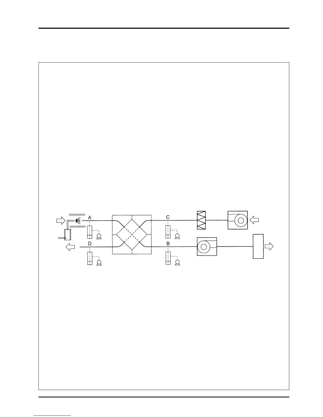
29
CHAPTER 3 ● General Technical Considerations
5. The Result of No Bacterial Cross Contamination for the Lossnay
Core and Determining Resistance of the Lossnay Core to Molds
Test report
This document reports the result that there is no bacterial cross contamination for the Lossnay Core.
(1) Object
The object of this test is to verify that there is no bacterial cross contamination from the outlet air to the inlet air of
the Lossnay Core in the heat recovery process.
(2) Client
MITSUBISHI ELECTRIC CO. NAKATSUGAWA WORKS.
(3) Test period
April 26, 1999 - May 28, 1999
(4) Test method
The configuration of the test equipment is shown below. The test bacteria suspension is sprayed in the outlet duct
at a pressure of 1.5 kg/cm
2
with a sprayer whose dominant particle size is 0.3 - 0.5 µm. The air sampling tubes
are installed at the each center of the locations of A, B, C, D, in the Lossnay inlet/outlet ducts so that their openings
are directly against the air flow, and then connected to the impinger outside the duct. The impinger is filled with
100 mL physiological salt solution. The airborne bacteria in the duct air are sampled at the rate of 10L air/minute
for three minutes.
(5) Test bacteria
The bacteria used in this test are as followed;
Bacillus subtilis IFO 3134
Pseudomonas diminuta IFO14213 (JIS K 3835 Method of testing bacteria trapping capability of precision
filtration film elements and modules; applicable to precision filtration film, etc. applied to air or liquid)
(6) Test result
The result of the test with Bacillus subtilis is shown in Table 1.
The result of the test with Pseudomonas diminuita is shown in Table 2.
Sprayer
Impinger
Impinger
Impinger
Fan
Fan
Safety cabinet
Impinger
LOSSNAY Core
HEPA filter
Page 33
30
CHAPTER 3 ● General Technical Considerations
Table 1 Test result with bacillus subtilis (CFU/30L air)
No. A B C D
1 5.4 × 10
4
5.6 × 10
4
< 10
3
< 10
3
2 8.5 × 10
3
7.5 × 10
3
< 10
3
< 10
3
3 7.5 × 10
3
< 10
3
< 10
3
< 10
3
4 1.2 × 10
4
1.2 × 10
4
< 10
3
< 10
3
5 1.8 × 10
4
1.5 × 10
3
< 10
3
< 10
3
Average 2.0 × 10
4
1.5 × 10
4
< 10
3
< 10
3
Table 2 Test result with pseudomonas diminuita (CFU/30L air)
No. A B C D
1 3.6 × 10
5
2.9 × 10
5
< 10
3
< 10
3
2 2.5 × 10
5
1.2 × 10
5
< 10
3
< 10
3
3 2.4 × 10
5
7.2 × 10
5
< 10
3
< 10
3
4 3.4 × 10
5
8.4 × 10
5
< 10
3
< 10
3
5 1.7 × 10
5
3.8 × 10
5
< 10
3
< 10
3
Average 2.7 × 10
5
4.7 × 10
5
< 10
3
< 10
3
(7) Considerations
Bacillus subtilis is commonly detected in the air and resistant to dry. Pseudomonas diminuita is susceptible to dry
and only a few exists in the air. However, it is used in the performance verification of the bacteria trapping filter
since the particle size is small (Cell diameter; 0.5 µm: Cell length 1.0 to 4.0 µm).
Both Bacillus subtilis and Pseudomonas diminuta are detected at the location A and B in the outlet side duct where
they are sprayed, but neither them are detected at location C (in the air filtered by the HEPA filter) and the location
D (in the air crossed in the Lossnay Core) on the inlet side.
Since the number of bacteria in the location A is substantially equal to one in the location B, it is estimated that
only a few bacteria are attached to the Lossnay Core on the outlet side. Also, no test bacteria is detected at the
location D where the air is crossed in the Lossnay Core. Therefore, it can be concluded that the bacteria attached
to the outlet side will not pass through the inlet side even after the heat is exchanged.
Shunji Okada
Manager, Biological Section
Kitasato Reseaarch Center of Enviromental Seiences
Page 34
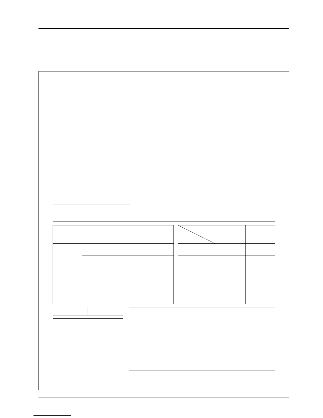
31
CHAPTER 3 ● General Technical Considerations
Material,
Mixture ratio,
Organization,
Fan number,
Density,
Weight (g/m
2
)
6. Flame-proofing Properties of Lossnay Core
The Lossnay Core satisfied all requirements of Paragraph 4-3 of the Fire Prevention Law Enforcement Rules.
Details of the tests carried out are as seen below.
Notation format 2 - (3)
Notification of flame-proofing property test
(For flame-proof materials and related items)
Flame-proofing committee test No., B-80028
April 17, 1980
Messrs.: Mitsubishi Electrical Corporation
Japan Flame-proofing committee
The results of the test, requested on April 8, 1980, are as follows.
Whereas
Part name
Product name
(Brand)
Air filter
Total heat recovery
unit
Lossnay
(ventilation fan) B
Specially treated paper:
(Partition (white) : Thickness 0.2 mm)
(Filler block (blue) : Thickness 0.2 mm)
Adhesive agent:
Vinyl acetate (Specific gravity ratio 2.6%)
600 g/m
2
Residual Residual
Carbonized
Test No. Test item flame dust area
(sec.) (sec.) (cm
2
)
1
0. 4.1 35.4
(Vertical)
2-min. 2
0. 7.7 38.2
heating (Vertical)
3
0. 1.4 35.9
(Horizontal)
6-sec.
1
0. 0. 26.3
heating after
(Vertical)
igniting
2
0. 0. 20.3
(Horizontal)
Test item Carbonization No. of flame
length
contact times
Test No. (cm) (times)
1
2
3
4
5
Evaluation Passing
Remarks
Test method
Application of Paragraph 4-3 Standards of Fire Prevention Laws
Enforcement Rules (Ministry of Home Affairs Ordinance No. 6, 1961)
(Thick cloth test)
Passing standards
Residual flame : 5 sec. or less
Residual dust : 20 sec. or less
Carburized area : 40 cm
2
or less
Washing test
Page 35
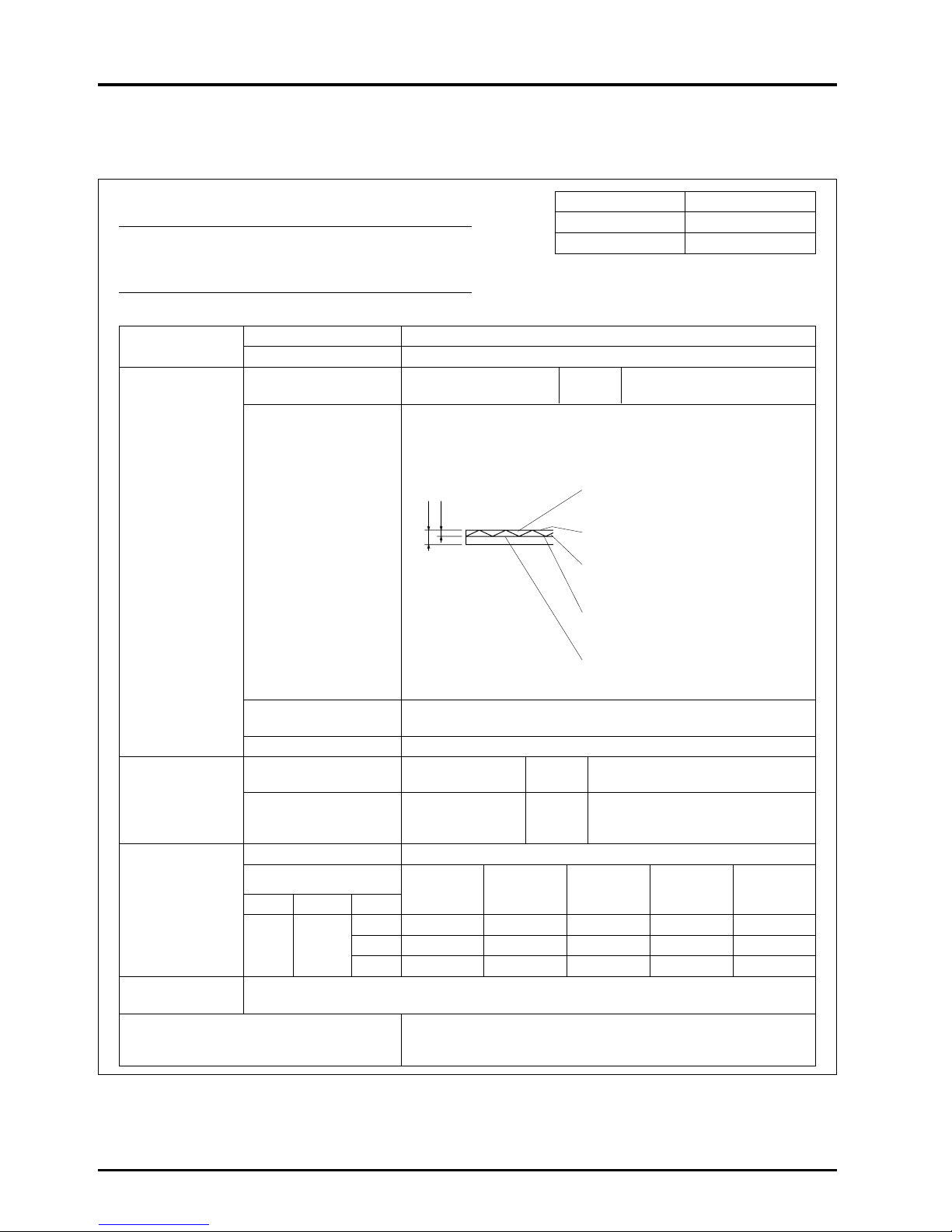
32
CHAPTER 3 ● General Technical Considerations
Applicant
Company name Mitsubishi Electric Corp., Nakatsugawa Works
Address 1-3 Komanba-cho, Nakatsugawa, Gifu
Specimen type
Single-face laminated Product Lossnay Core
corrugated board name (Total heat recovery unit)
Single-face laminated corrugated board
... Thickness: 4 mm
(Single-face corrugated board with
2 mm cell size laminated alternately at
right angle)
Partition (Liner paper) Flame-proof
treated paper
...
Thickness: 0.085 mm, Weight: 70 g/m
2
Material structure and Adhesive agent ... Vinyl acetate resin
Specimen cross-sectional ... Weight: 30 g/m
2
(Solid)
and test body
diagram, etc.
Filler (Flute paper)
... Colored wood free paper
...
Thickness: 0.093 mm, Weight: 79 g/m
2
Adhesive agent
... Vinyl acetate resin
... Weight: 30 g/m
2
(Solid)
Partition (Liner paper) Flame-proof
treated paper
...
Thickness: 0.085 mm, Weight: 70 g/m
2
Test body size and
300 (Long side) × 200 (Short side) × 4 (Thickness)
thickness (mm)
Test body direction The longer side is the vertical side.
Testing standards
Pre-treatment of Heating
Heating surface class and direction
Testing
test body time
method
JIS A 1322
Method A
The direction of which the corrugated
(45° Meckelian burner
(drying method)
3 min. board fold was vertical was set as the
method) front of the heating surface.
Test date October 5, 1993
Test position
Residual Residual
Carbonized Discoloration
frame dust
length (Vertical × length (Vertical ×
Remarks
Test results
Class Direction No. (sec.) (sec.)
Horizontal) (cm) Horizontal) (cm)
1 0 0 8.2 × 4.7 18.7 × 7.3
Front Vertical 2 0 0 8.4 × 4.9 24.3 × 7.8 *1
3 0 0 7.4 × 5.0 22.0 × 8.4
Evaluation
The specimen conforms to Class 2 flame-proofing (heating time: 3 min.) according to the “Fire
retardancy test methods of thin materials for construction” as set forth by JIS A 1322.
Material Testing Laboratory
Persons in charge of testing Laboratory chief: Hiroshi Tamura, Technicians: Shigeru
Fujikawa, Nobuaki Oohiro, Tetsuya Ogawa
The Lossnay Core was also tested at the Japan Construction General Laboratories according to the fire retardancy test
methods of thin materials for construction as set forth by JIS A 1322. The material was evaluated as Class 2 flame retardant.
Details of the tests carried out are shown below.
Flame-proofing property test report
Messrs. Mitsubishi Electric Corp.,
Nakatsugawa Works
Acceptance No. VF-93-11-(2)
Data of acceptance September 7, 1993
Data of report October 12, 1993
Japan Construction General Laboratories
5-8-1 Fujishirodai, Suita City 565
Tel: 06-872-0391
Hiorshi Wakabayashi Dr. of Engineering, Director
Note: Immediately after starting heating, the flame was ignited simultaneously with the generation of smoke. Penetration was
observed approx. 2 min. 30 sec., after heating was started. There were no further changes.
The Lossnay core was tested at the Underwriters Laboratories Inc. according to the standard of UL94, Test for
Flammability of Plastic Materials for Parts in Devices and Appliances, 1998.
The material was evaluated as per 5VA classified of flammability.
4mm
2mm
Page 36
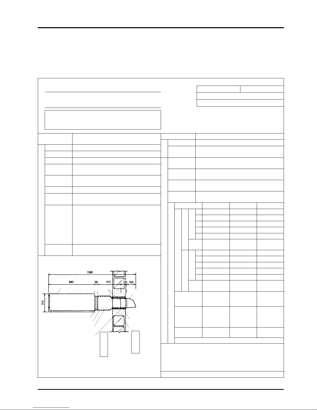
33
CHAPTER 3 ● General Technical Considerations
Testing facility General Building Research Corporation
Address 1-3 Komanba-cho, Nakatsugawa, Gifu
Company Mitsubishi Electric Corporation
name Nakatsugawa Works
Testing According to “soundproofing effect test” in
method Ministry of Construction No. 108
Measurement
March 9, 1979
date
Measurement
Temperature: 12.5°C, humidity: 77%
conditions
Soundproof area
W 580 × H 190
dimensions
Centre frequency
125 Hz 500 Hz 2,000 Hz
1 101.5 96.5 98.5
2 99.0 ——
3 100.0 97.5 98.5
4 102.0 ——
5 101.5 96.5 98.5
Average
100.9 96.9 98.5
level
1 81.5 63.5 53.0
2 79.5 ——
3 79.5 63.0 43.0
4 82.5 ——
5 81.5 62.5 43.5
Average
81.1 63.0 43.2
level
Average sound
pressure level
19.8 33.9 55.3
difference (dB)
Sound absorbed
by reverberation
chamber on
2.79 3.90 7.22
reception side (m2)
Sound transmis-
5.8 18.4 37.1
sion loss (dB)
Refer to page 35 for details of test results
Remarks
The soundproofed area of the specimen is small in this test, and as
the transmission of sound though the surrounding concrete block wall
cannot be ignored, the concrete block wall was measured after the
main test, and the main test measurement results were corrected.
Persons in charge of testing: Mitsuo Morimoto, Toshifumi Murakami
Measurement results
Each measured sound pressure level (dB)
Certificate
IVA-78-122
number
Product name
LGH-50E
Item name Heat exchange-type ventilator
Application Ventilation
Date of
October 1978
manufacture
Place of
General Building Research Corporation
assembly
Dimensions W 1250 × H 310 × D 1589
Area ———
concentration
Remarks An existing hole (4000 mm × 3000 mm) was
covered with a hollow concrete block with
Cultures, double-faced mortar (thickness 20 mm each),
specimen with a wood frame with inner dimension of
installation 580 mm × 190 mm × 230 mm being installed.
method at The supply/exhaust box and duct was
test facility mounted in this, and the main unit and
weather cover was mounted.
Peripheral
Oil clay was filled around the sound source
sections
Specimen configuration (dimensions mm)
Refer to appendix 1, 2 for details. S: 1/20
7. Lossnay Core’s Soundproofing Properties Test
As the Lossnay Core is made of paper and the permeable holes are extremely small, the Core has outstanding soundproofing
properties and is appropriate for ventilation in soundproof rooms.
For example, the exposed ceiling-type LGH-50E has soundproofing characteristics of 33.9 dB with a center frequency of 400
Hz. This means that a sound source of 96.9 dB can be shielded to 63 dB.
Soundproofing effect test results
For Mitsubishi Electric Corporation
Nakatsugawa Works
Test number IVA-78-122
Acceptance data : February 22, 1979
Report : May 24, 1979
General Building Reseach Corporation
Fujishirodai 5-125, Suita-shi, Osaka-Fu, Japan
Person in charge of testing: Takeshi Tokura
No. 122-1
The results of the tests are as noted below.
General Building Research Corporation
General Manager, S. Okushima
Remarks
Urethane foam (15 mm thick) was stuck onto the inside of the duct
and feed/exhaust box.
Specimen
Client
Sound source side
Reception side
Measurement point
Measurement point
Sound transmission loss test
Steel plate
thickness: 0.8
Internal flange hole
with fixing screw
Weather cover
Steel plate thickness: 0.6
Wood frame
thickness: 20
Flange steel plate thickness: 1.6
Duct steel plate thickness: 1.6
Urethane foam thickness: 15 0.072 m
2
Feed/exhaust box
Steel plate thickness: 1.0
Sound
reception side
Sound
source side
Mortar
Page 37
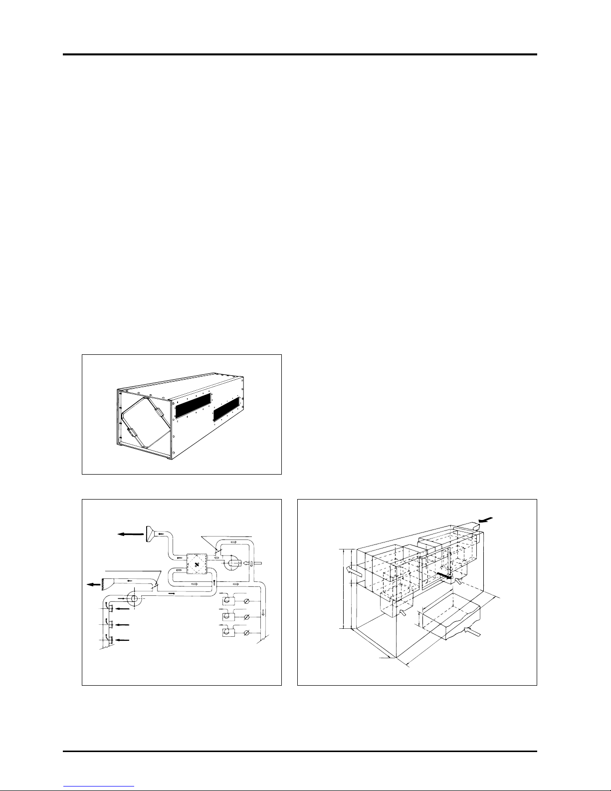
34
CHAPTER 3 ● General Technical Considerations
8. Change in Lossnay Core Over Time
The following details show an example of a building that has installed the Lossnay units, from which it is possible to assess the
change in the units over time.
8.1 Outline of building where Lossnay is installed
(1) Building name : Meiji Seimei, Nagoya Office/shop building
1-1 Shinsakae-machi Naka-ku, Nagoya
(2) No. of floors : 16 above ground, 2-storey penthouse, 4 basement floors
(3) Total floor space : 38,893 m
2
(4) Reference floor space : 1,388 m
2
8.2 Outline of installed ventilation equipment
(1) Air handling method : 4 fan coil units (perimeter zone) per floor
Chilling unit : Absorption-type 250 kT × 1 unit, turbo 250 kT × 2 units
Gas direct heating/cooling boiler : 340 kT, heating 1400 × 10
3
kcal/h
(2) Ventilation method : Air - air total heat recovery unit “Lossnay
”
LS-200 × 18 units installed in penthouse.
Outdoor air treatment volume 46,231 CMH,
Exhaust air treatment volume 54,335 CMH.
(3) Lossnay outline diagram : LS-200 (with four Lossnay Cores)
AC
AC
AC
4080
4300
10040
2000
3200
700
1300 1300
Lossnay
Lossnay
L
ossna
y
Lo
ssnay
S
A
E
A
O A
R
A
Lossnay duct system diagram General diagram of penthouse Lossnay chamber
Unit (mm)
Exhaust air
OA side by-pass damper
Lossnay
RA fan
(for exhaust)
Outdoor
air
OA fan
(for intake)
RA side
by-pass damper
Page 38
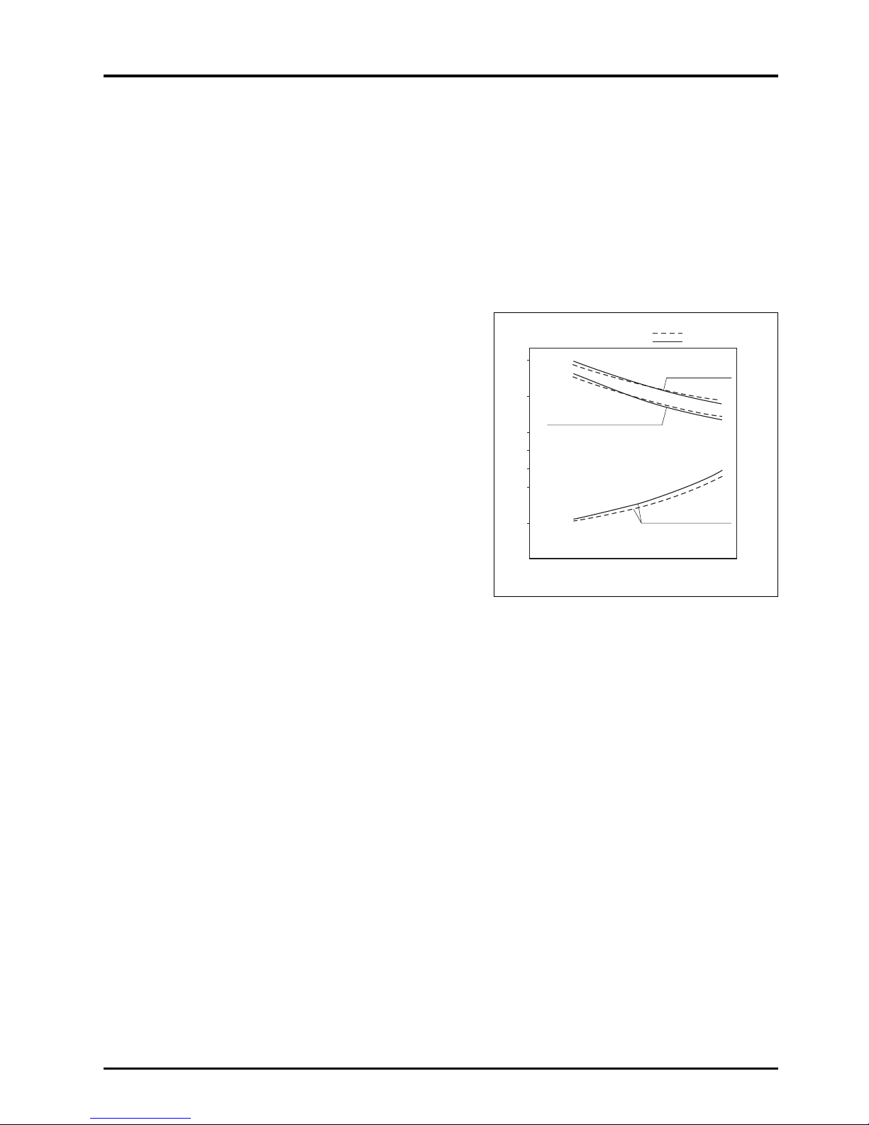
35
CHAPTER 3 ● General Technical Considerations
8.3 Outline of Lossnay operation
(1) Start of operation : September 1972
Start of daily operation : 7:00
Average daily operation 11 hours
End of daily operation : 18:00
(2) Inspection after usage : November 1983
(3) Bypass operation month : Three months of April, May, June
(4) Total operation time : (134 – 33) months × 25 days/month × 11 hours/day = 27,775 hours
8.4 Characteristics in change of Lossnay Core over time
Two Lossnay Cores were removed from the 18 Lossnay LS-200
installed in the Meiji Seimei Building, and the static pressure loss
and exchange efficiencies were measured. The comparison with
the initial value is shown on the right. The appropriate air volume
for one Lossnay Core is 500 m
3
/hr, and the measurement point
was ±200 m
3
/hr of this value.
300
0
10
20
60
30
70
80
90
500 700
Characteristics in change of Lossnay Core over time
8.5 Conclusion
(1) Changes in the characteristics of the Lossnay Core after approximately eleven years of use and an estimated 28,000
operation hours were not found.
In numerical values, the static pressure loss was 15 to 16 mmH
2O at 500 m
3
/hr which was a 1 mmH2O increase, and the
exchange efficiencies had decreased slightly at above 500 m
3
/hr. However, this is considered to be insignificant and
remained in the measurement error range.
(2) Looking at the appearance, the Core surface was black with dust, but there were no gaps, deformation or mold that would
pose problems during practical use.
}
Data from delivery (1974)
Data from 1983
Treated air volume (m3/h)
Heat recovery
efficiency
Enthalpy recovery
efficiency during heating
Static pressure Loss
Static pressure loss (mmH2O) Recovery efficiencies (%)
Page 39
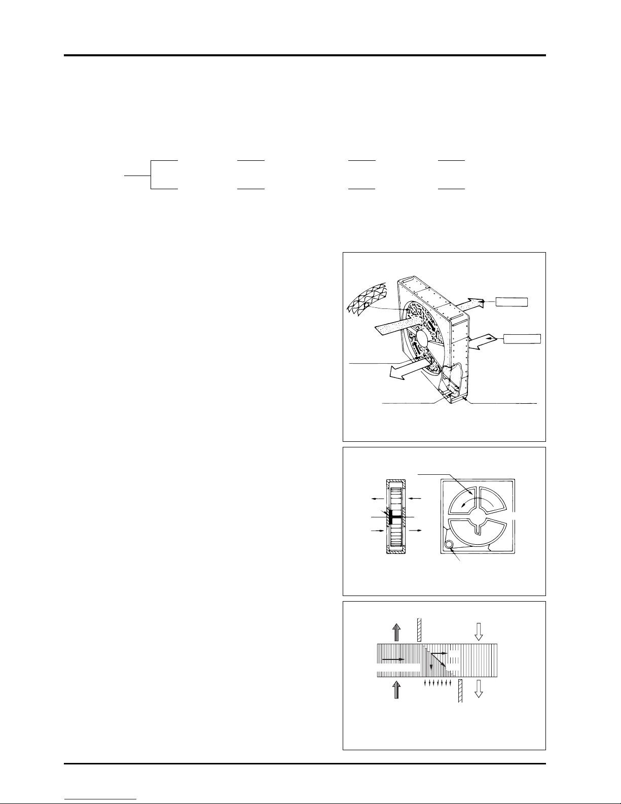
36
CHAPTER 3 ● General Technical Considerations
9. Comparison of Heat Recovery Techniques
The methods by which heat recovery devices can be categorised may be considered as follows:
Basic methods of total heat exchangersa
9.1 Principle construction of rotary-type
●
The rotary-type heat recovery unit is composed of a rotor that
has a layered honeycomb structure made of kraft paper, drive
motor and housing.
A large quantity of moisture absorbent material (lithium chloride,
etc.) is applied onto the rotor, and humidity is transferred.
The rotor is rotated eight times a minute by the drive motor.
●
The principle of this rotary-type is for example when cooling, the
high temperature and high humidity fresh air passes through the
rotor, with the heat and humidity being absorbed by the rotor.
As the rotor is rotating, it moves into the exhaust air passage,
and the heat and humidity is discharged to outdoors because
the exhaust is cool and has a low humidity.
The rotor rotates and returns to the fresh air passage to absorb
the heat and humidity again.
●
Function of purge sector
There are two separation plates (purge sector) in the front and
back of the rotor to separate the flow of the air. As one of the
plates is slightly shifted, part of the fresh air always flows into the
exhaust air passage to prevent the exhaust air and fresh air from
mixing. (A balanced pressure difference is required.)
Type Method Air flow Country of
Static Conductive Cross-flow
development
Heat recovery
(Mitsubishi Lossnay) transmission type Japan
principle
Rotary type Heat accumulation/ Counterflow Sweden
humidity accumulation
type
A
Vs
B
Vr
When a purge sector is mounted, the introduction of the exhaust
air in the rotor to the air on the supply side can be prevented.
Vr: Rotor speed, Vs: Air speed in relief section
Approx. 1.5 ø
Purge sector
Exhaust
Fresh air
Drive motor
Power supply
AC 200 V 50/60 Hz
Rotor
Bearing
Supply air Fresh air
Return air Exhaust
Drive motor
Room side
Purge sector
Fresh sir
Return air
Rotor rotation direction
Page 40
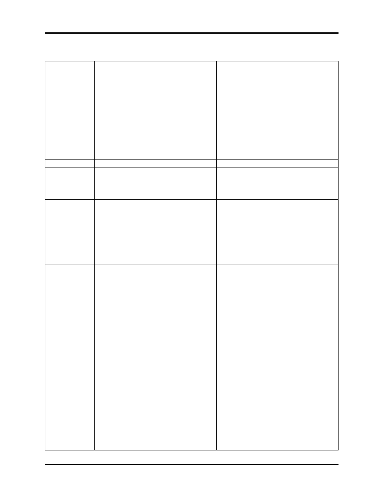
37
CHAPTER 3 ● General Technical Considerations
9.2 Comparison of static-type and rotary-type heat recovery units
Item
Construction/
principle
Moving parts
Material quality
Mounting of prefilter
Element clogging
Air leakage
Gas transmission
rate
Bacteria
transmission rate
Operation during
off-seasons
Maintenance
Life
Model system and
comparison
Standard treatment
air volume
Enthalpy recovery
efficiency
Pressure loss
Installation space
(W × D × H)
Static-type
<Conductive transmission-type: cross-flow>
Static-type transmission total heat recovery unit
with orthogonally layered honeycomb shaped
treated paper formed into multiple layers.
● As the supply air and exhaust air pass through
different passages (sequentially layered), the air
passages are completely separated.
● None
Fixed core
Treated paper
Required (periodic cleaning required)
● Occurs (state where dirt adheres onto element air
passage surface. However, this is easily removed
with a vacuum cleaner.)
Approximately 2.5% air leak at standard fan
position.
Leaks on the air supply side can be reduced to 0 by
leaking the loss air volume (approx. 10%) on the
exhaust side with the fan position to the core.
● Gas transmission ( Ammonia : 28%,
hydrogen sulfide : approx. 6.7%)
● Low (As air intake/exhaust are separate,
transmission is low.)
Bypass circuit required (OK on one side of air
intake and exhaust air outlet passage)
Core cleaning: More than once a year
The core surface will clog with lint and dirt, but
cleaning is easy with a vacuum cleaner.
Only the two core air passage intakes need to be
cleaned.
Core: Semi-permanent (10 years or more)
(The static-type does not break.)
o
Available from small to large. Example
o
Characteristic design of small LU-1605
and medium models possible.
Large models are easy to
match to machine room layout.
40 to 25,000 m
3
/h 8,000 m3/h
Temperature:77%
Enthalpy
Heating : 71%
Cooling : 66%
17 mmAg
Effective for small to medium capacity
600 × 2100 × 2540
(Layout is free according to combination.)
Rotary-type
<Heat accumulation/humidity accumulationtype: counterflow>
The rotor core is composed of honeycomb-shaped
kraft paper, etc., to which a moisture absorbent is
applied (lithium chloride, etc.). This rotor is rotated,
and heat accumulation/humidity accumulation heat discharge/humidity discharge of total heat
exchange is performed by passing the exhaust and
intake airs into a honeycomb passage.
× Supply air and exhaust airs flow into the same air
passage because of the rotary-type construction.
× Used (rotor driven with belt by gear motor)
Rotor core (8RPM)
Treated paper, aluminum plates, etc.
Required (periodic cleaning required)
×
Occurs (Dust is smeared into element air passage filter.)
(The dust adhered onto the core surface is smeared
into the air passage by the purge sector packing.
Thus, it cannot be removed easily and the air
volume decreases.)
× Purged air volume occurs
To prevent leakage of exhaust to the air intake side, a
purge air volume (6 to 14%) leak is created to the
exhaust side. Thus, there are problems in the purge
sector operation conditions (pressure difference,
speed), and the air volume balance must be balanced.
×
Gas transmission (Ammonia : 45-57%,
hydrogen sulfide : approx. 3.2-4%)
× High (As air intake/exhaust are the same,
transmission is high.)
Bypass circuit required (Required on both air intake
and exhaust air outlet sides)
(In theory, operation is possible by stopping the rotation,
but the core will over-absorb, causing drainage.)
Core
cleaning: Once every one to two years
Cleaning is difficult as dust is smeared into core
with the packing.
× Gear motor for rotor drive : Periodic inspection
× Rotor bearing, rotor drive belt : Periodic inspection
Core: Semi-permanent (10 years or more)
(Periodic replacement is required according to the
rotor bearings and core clogging.)
× Rotor drive belt : Periodic replacement
× Drive motor, rotor bearing : Periodic replacement
Large type only Example
× Small models are difficult to EV-1500
design because of the rotor
magnitude.
o
100 to 63,000 m3/h 8,000 m3/h
74%
18 mmAg
Large capacity models are 320 × 1700 × 1700
effective
Measure of useability
●
High
o
Average × Poor
Page 41

Page 42

CHAPTER 4
Characteristics
Page 43

40
CHAPTER 4 ● Characteristics
1. How to Read the LGH Series Lossnay Characteristic Curves
1.1 Obtaining characteristics from static pressure loss
(1) Static pressure loss from straight pipe duct length (at required air volume)
(2) Static pressure loss at curved section (at required air volume)
(3) Static pressure loss of related parts (at required air volume)
Total static pressure loss
Estimated static pressure loss curve
obtained from 1 and 2
3
Air volume
Static
pressure
4 Intersection with air volume static
pressure characteristic curve
5 Air volume at application point
2 Total static
pressure loss
6 Static pressure loss at
application point
1 Required air
volume
2. Obtaining the Static Pressure Loss
2.1 How to read the air volume - static pressure curve
It is important to know the amount of static pressure loss applied
onto the Lossnay when using parts such as ducts for the air
distribution. If the static pressure increases, the air volume will
decrease. The air volume - static pressure curve (Q-H curve)
shows this percentage. A static pressure of 19.6 Pa (2 mmH
2
O) is
applied on to point A, and the air volume is 500 m
3
/h. The duct
resistivity curve shows how the static pressure is applied when a
duct is connected to the Lossnay. Thus, the L = 9.97 m duct
resistivity curve in the diagram is the curve that shows how the
static pressure is applied when a 10 m duct is connected. The
intersecting point A with the Lossnay Q-H curve is the operation
point.
Duct resistivity curve
The duct resistivity curve shows how much static pressure a duct will apply on the Lossnay, as explained above.
In general, the interrelation between the duct and static pressure is as follows:
500m3/h
19.6 Pa
(2 mmH
2O)
L = 10m
A
20 m
15 m
10 m
5 m
Duct Static pressure
When duct is long Increases
If length is the same but the air volume
Increases
increases
If the duct diameter is narrow Increases
If the duct inner surface is rough
Increases
(such as a spiral)
Q-H curve
Static pressure
Duct resistivity curve
Air volume
Air volume
Static pressure
(Duct length)
Page 44

How to read Table 3
Select the unit as per each duct. In the
above example, the 520 rectangular pipe
only goes as far as 17. Thus, the long side,
short side and converted circular pipe
values are all multiplied by 100. The point
560 where the two lines cross is hence the
value where the rectangular pipe equates to
the circular pipe.
41
CHAPTER 4 ● Characteristics
Reference
●
The pressure loss caused by the outdoor air is as follows:
Pressure loss caused by outdoor air (Pa)
=
r
× V2=
1.2
× (velocity)
2
22
r : Air weight 1.2 kg/m
3
v : Velocity (m/s)
2.2 Calculation of duct pressure loss
When selecting a model that is to be used with a duct, calculate the volumes according to Tables 3, 4, 5 and 6, and then select
the unit according to the air volume and static pressure curve.
{
(2) How to obtain the duct resistivity
Table 4 Circular duct friction loss
(steel plate duct, inner roughness ε = 0.18 mm)
(1)
Calculation of a rectangular pipe
Table 3 Conversion table from
rectangular pipe to circular pipe
1
1234567891011121314151617
2
3
4
5
6
7
8
9
10
11
12
13
14
15
16
17
18
19
20
21
21
20
19
18
17
16
15
14
13
12
1
1
10
9
8
7
6
22
23
24
25
5
4
3
2
1
100
200
400
600
800
1,000
2,000
4,000
6,000
8,000
10,000
20,000
40,000
60,000
80,000
100,000
200,000
400,000
600,000
800,000
1,000,000
9
8
7
6
5
18
16
14
12
10
25
20
35
30
45
40
250
200
350
300
90
80
70
60
50
180
160
140
120
d=100cm
d=400cm
d=500cm
3
10
20
30
40
50
100
200
4
5
6
7
8
9
10
15
20
25
30
40
6
7
8
9
10
1
5
2
0
2
5
3
0
4
0
V=50m/s
V=50
How to read Table 4
The point where the line of the circular duct
diameter (leftward slanting line) and of the
required air velocity (horizontal line)
intersect is the pressure loss per 1 m of
duct.
The value of the slanted line to the lower
right of the intersecting point is the average
velocity.
(Outline of Table 4)
Long side of
rectangular pipe
Circular pipe diameter
The circular pipe diameter having equal hydraulic radius
Short side of
rectangular pipe
Air volume (m
3
/h)
Friction loss (Pa/m)
0.1 0.2 0.4 0.6 0.8 1.0 2.0 4.0 6.0 8.0 10 20 30 40 50 60 80 100
Friction loss (mmH2O/m)
0.1 0.2 0.4 0.6 0.8 1.0 2.0 4.0 6.0 8.0 10 20 30 40 50 60 80 100
2.0
5.2
5.2
2
6
8
10
12
14
16
18
4
2 4 6 8 10 12 14 16 18
560mm
Air volume: 7000 m
3
/h
Duct diameter
Avera ge
velocity
8 m/s
Resistance
0.12 mm H
2O/m (1.17Pa/m)
Outdoor air pressure (mmH2O)
Outdoor air (m/s)
Page 45

42
CHAPTER 4 ● Characteristics
The figure obtained from Table 4 must then be corrected for duct type at various velocities. This can be done using Table 5
below.
Table 5 Friction coefficient compensation table
An alternative, more detailed method for determining the pressure loss in duct work is as shown using the following formula:
Duct inner surface Example
Average velocity (m/sec)
5101520
Very rough surface Concrete finish 1.7 1.8 1.85 1.9
Rough Mortar finish 1.3 1.35 1.35 1.37
Very smooth Drawn steel pipe Vinyl pipe 0.92 0.85 0.82 0.8
Circular pipe section pressure loss
∆p = λ
·· ·
v
2
(Pa)
∆p = C
··
v
2
(Pa)
= 0.6 C ·v
2
λ : Friction resistance coefficient (smooth pipe 0.025)
C : Local loss coefficient (refer to Table 6)
d : Duct diameter (m)
: Duct length (m)
ρ
: Air weight (1.2 kg/m2)
v : Wind velocity (m/s)
R
d
ρ
2
ρ
2
R
Page 46

Duct
No.
section
Outline diagram
Conditions
C
value
12 Transformer 0.15 9D
Abrupt
13
Entrance
0.50 30D
Abrupt
14
Exit
1.0 60D
Bellmouth
15
Entrance
0.03 2D
Bellmouth
16
Exit
1.0 60D
Re-entrant
17
inlet
0.85 51D
V
1/V2 = 0 2.8 170D
0.25 2.4 140D
Sharp edge
0.50 1.9 110D
18
round orifice
0.75 1.5 90D
1 1.0 60D
Loss is for
V
2
20° 0.02
Pipe inlet
40° 0.03
19
(with
β 60° 0.05
circular
90° 0.11
hood)
120° 0.20
20° 0.03
Pipe inlet
40° 0.08
20
(with
β 50° 0.12
rectangular
90° 0.19
hood)
120° 0.27
V
1/V2 = 0 0.5 30D
0.25 0.45 27D
Abrupt
0.50 0.32 19D
21
contraction
0.75 0.18 11D
Loss is for
V
2
V1/V2 = 0 1.0 60D
0.20 0.64 39D
Abrupt
0.40 0.36 22D
22
expansion
0.60 0.16 9D
0.80 0.04 2D
Loss is for
V
1
Suction
inlet
0.2 35
23 (punched
0.4 7.6
narrow
0.6 3.0
plate)
0.8 1.2
43
CHAPTER 4 ● Characteristics
(3) How to calculate curved sections
Table 6 List of pressure losses in each duct section
Length of
equivalent
circular
pipe
No. of
vanes
With or without
vanes,
rectangular or
circular
1/2 times value
for similar 90°
Length of
equivalent
circular
pipe
Free are ratio
14° or less
D
Duct
No.
section
Outline diagram
Conditions
C
value
R/D = 0.5 0.73 43D
90° =
0.75
0.38 23D
1 Smooth = 1.0 0.26 15D
Elbow = 1.5 0.17 10D
= 2.0 0.15 9D
W/D R/D
0.5 1.30 79D
0.5
0.75 0.47 29D
Rectangular 1.0 0.28 17D
2 Radius 1.5 0.18 11D
Elbow 0.5 0.95 57D
1-3
0.75 0.33 20D
1.0 0.20 12D
1.5 0.13 8D
R/D
0.5 0.70 42D
Rectangular 1
0.75 0.16 10D
Vaned
1.0 0.13 8D
3
Radius
1.5 0.12 7D
Elbow
0.5 0.45 27D
2
0.75 0.12 7D
1.0 0.10 6D
1.5 0.15 9D
90°
4 Miter 0.87 53D
Elbow
Rectangular
5
Square
1.25 76D
Square
Elbow
Rectangular
6
Vaned
0.35 21D
Square
Elbow
Rectangular
7
Vaned
Square
Junction
Same loss as circular duct.
Rectangular
Velocity is based on inlet.
8
Vaned
Radius
Junction
45°
9 Smooth
Elbow
a = 5° 0.17 10D
10° 0.28 17D
20° 0.45 27D
10 Expansion 30° 0.59 36D
40° 0.73 43D
Loss is for
hV
1 - hV2
a = 30° 0.02 1D
45° 0.04 2D
11 Contraction 60° 0.07 4D
Loss is for
V
2
Page 47

High notch air volume at 60 Hz
44
CHAPTER 4 ● Characteristics
3. How to Obtain Efficiency from Characteristic Curves
3.1 Commercial-use Lossnay
How to read Commercial-use Lossnay characteristic curve
●
Obtaining the efficiency when supply air and exhaust air volumes differ
The efficiency obtained from the intake side air value in each characteristic curve can be corrected with the air volume ratio
in the chart on the right.
If the intake side and exhaust side duct lengths differ greatly or if a differential air volume is required, obtain the intake side
efficiency from the chart on the right.
3.2 Building-use Lossnay
How to read LP type Lossnay characteristic curve
How to read LU, LUT, and LUP type Lossnay characteristic curves
90
0.5 0.6 0.7
50 60 70 80 90 100
0.8 0.9 1.0 1.1 1.4
1.2 1.3
80
70
60
50
40
Efficiencyobtainedfromsupplysideairvolume(%)
Heatrecovery
efficiency
(%)
Airvolumeratio=
Exhaustairvolume
Supplyairvolume
Correctedheatrecoveryefficiency(%)
Heatrecovery
efficiency
whenexhaust
airvolumeand
supplyairvolume
arethesame
Requiredstatic
pressureon
supplyside
Requiredairvolumeonexhaustside
Requiredairvolumeonsupplyside
Airvolumeratio=
Exhaustairvolume
Supplyairvolume
Efficiencycorrectioncurve
6
5
3
Requiredstatic
pressureon
exhaustside
4
Enthalpyrecoveryefficiency(heating)
(cooling)
Enthalpy
recovery
efficiency
Heatrecoveryefficiency
onsupplysidewhen
exhaustairvolumeand
supplyairvolumediffer
6
1
2
T
e
m
p
e
ra
tu
re
re
c
o
v
e
ry
e
ffic
ie
n
c
y
Heatrecovery
efficiency
whenexhaust
airvolumeand
supplyairvolume
arethesame
7
1
Staticpressure
lossonsupply
side
4
Staticpressure
losson
exhaustside
5
Airvolumeratio=
Exhaustairvolume
Supplyairvolume
Efficiencycorrectioncurve
6
Requiredairvolumeonexhaustside
Requiredairvolumeonsupplyside
Heatrecoveryefficiency
onsupplysidewhen
exhaustairvolumeand
supplyairvolumediffer
7
2
3
Staticpressureinsideunit
Tem
peraturerecoveryefficiency
Enthalpy
recovery
efficiency(heating)
Enthalpy
recovery
efficiency(cooling)
Recovery
efficiency
Static pressure
outside unit
Temperature
recovery efficiency
Enthalpy recovery efficiency
(heating)
Enthalpy recovery efficiency
(cooling)
Static pressure loss related parts
(straight pipe equivalent length total)
Pipe length
1
2
3
Recovery efficiency
Low notch air volume at 60 Hz
Total static pressure loss (or total straight pipe equivalent length)
Static pressure outside unit
At 50 Hz, equivalent to 60 Hz at dotted line
Efficiency obtained
with air volume on
supply side from
characteristic curve
Air volume ratio =
Exhaust air volume
Supply air volume
Supply side efficiency
after correction
5
4
Heat recovery efficiency correction curve
Page 48
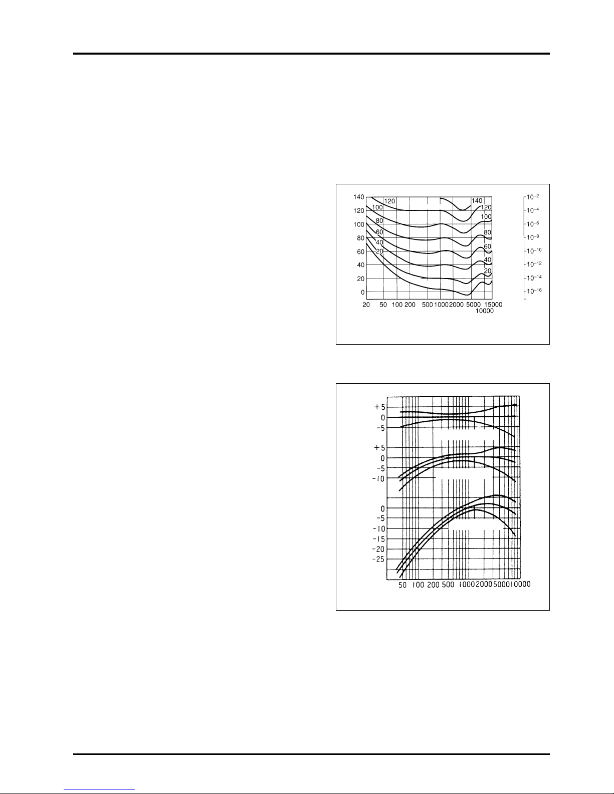
45
CHAPTER 4 ● Characteristics
4. Sound
Sound is emitted when any object is excited causing it to vibrate. The object that vibrates is called the sound source, and the
energy that is generated at the source is transmitted through the air to the human ear. Humans can hear the sound only when
the ear drum vibrates.
4.1 Sound level and auditory perception
Sound level is the sound wave energy that passes through a unit
area in a unit time, and is expressed in dB (decibel) units.
The sound heard by the human ear differs according to the
strength of the sound and the frequency, and the relation to the
pure tone sound is as shown on the right. The vertical line shows
the strength of the sound and the horizontal line shows the
frequency. For frequencies between 20 Hz to 15,000 Hz which
can be felt by the human ear, the strength of sound that can be felt
that is equivalent to a 1,000 Hz sound is obtained for each
frequency. The point where these points cross is the sound level
curve, and a sound pressure level numerical value of 1,000 Hz is
expressed. These are called units of phons. For example, the
point on the 60 curve is perceived as 60 phons.
●
On average, the human senses a sound that is less than 1,000
Hz as rather weak, and a sound between 2,000 to 5,000 Hz as
strong.
4.2 How to measure sound levels
A sound level meter (JIS C1502) is used to measure sound levels.
This sound level meter has three characteristics (A, B and C
characteristics) as shown on the right. These represent various
sound wave characteristics.
Generally, the A characteristic, which is the most similar to the
human ear, is used.
Sound level (dB)
Frequency (Hz)
M
in
im
um
a
u
dible
va
lve
120 dB
100
–200
–20
–2
–0.2
–0.02
–0.002
–0.0002
80
60
40
20
4.2
Response (dB)
Frequency (Hz)
C characteristic
B characteristic
A characteristic
Sound
presure
(Microbar)
Sound
strength
(W / cm
2
)
ISO audio perception curve
Page 49
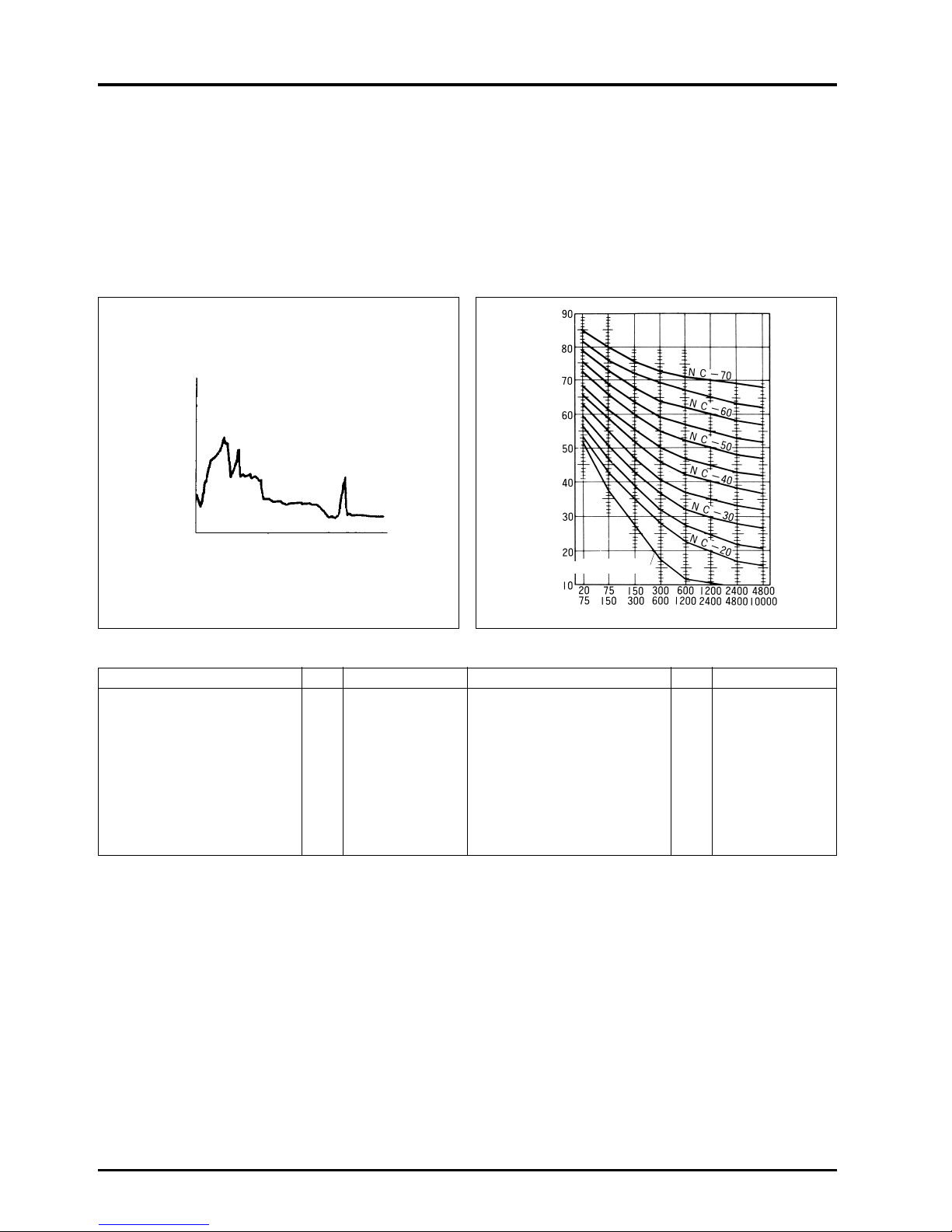
46
CHAPTER 4 ● Characteristics
Room application
dB
NC value Room application
dB
NC value
Broadcasting studio 25 15 - 20 Cinema 40 30
Music hall 30 20 Hospital 35 30
Theatre (approx. 500 seats) 35 20 - 25 Library 40 30
Classroom 40 25 Small office 45 30 - 35
Conference room 40 25 Restaurant 50 45
Apartment 40 25 - 30 Gymnasium 55 50
Hotel 40 25 - 30 Large conference room 50 45
Housing (room) 40 25 - 30 Factory 70 50 or more
4.3 Frequency analysis of sound
It is said that the human ear senses differently according to the frequency. However, the sound generated from a vibration is
not limited to one frequency, but instead, various frequencies are generated at differing levels. This is expressed by the NC
curve, which is determined according to the difficulty of hearing a conversation.
●
Even if the sound is a very low level, it is annoying if a specific frequency is emitted very loudly.
These sounds are suppressed to a minimum during product design stages, but, the sound may become very disturbing with
resonance of the ceiling, wall, etc.
Example Continuous frequency analysis NC curve
●
Tolerable noise levels and NC values according to room application
Frequency band (Hz)
Level (dB)
Frequency (Hz)
SPL (dB)
Min. audible limit
Page 50
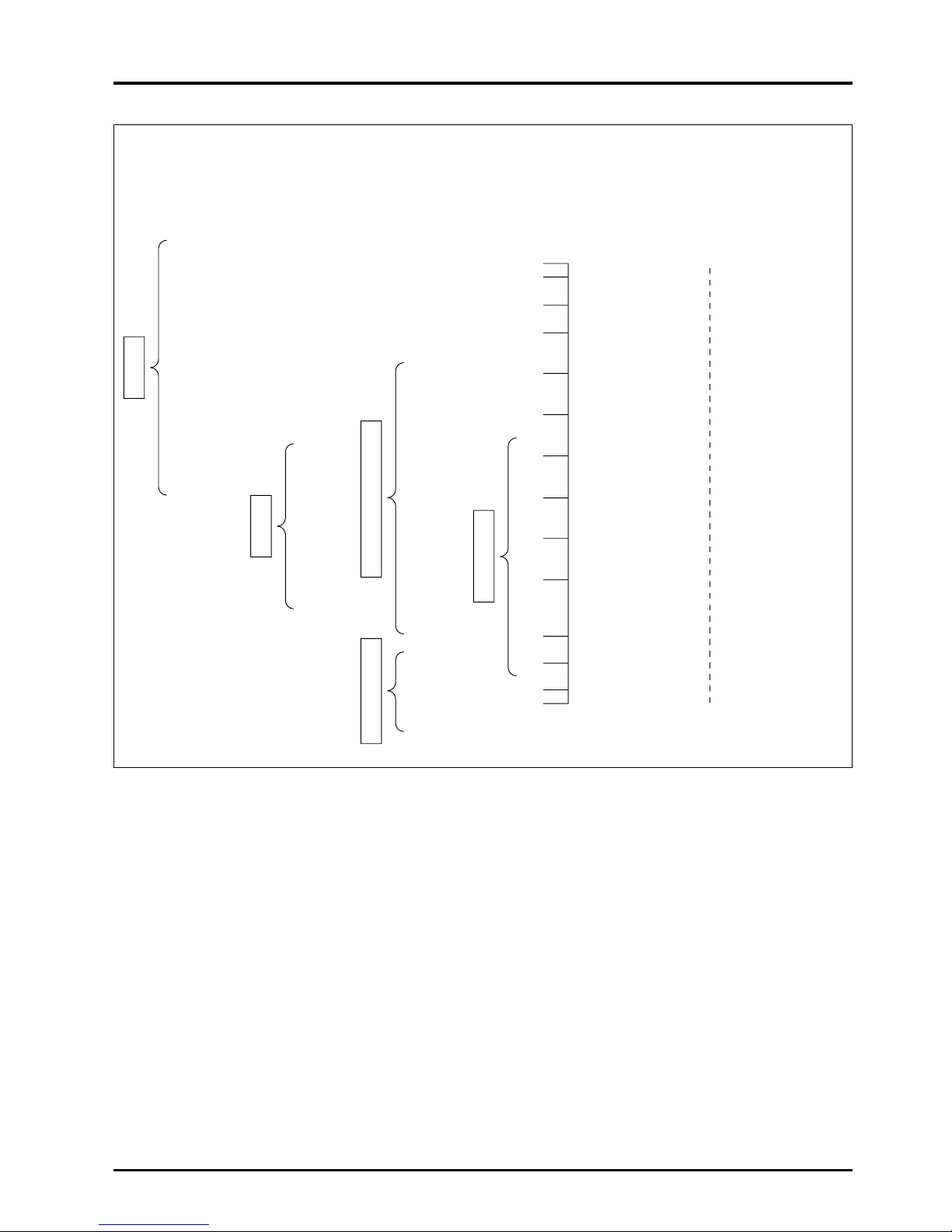
47
CHAPTER 4 ● Characteristics
* Approximate values of noise levels using practical examples
The following diagram shows noises found near us.
Approximate degree of noise levels can be seen with these examples.
* Noise levels and perception
Boiler making
Forginb, rivetting,
rock drilling
Crusher
Engine, large
motor
Noisy factory
Normal
machine
factory
(dB) (Perception at site)
130 Painful to ear
120 Near airplane engine
110 Slight pain to ear Automobile horn
(2 m away)
100 Want to cover ear Train with open
window in tunnel
90 Conversation with Train passing on
person in front of you overhead tracks
is not possible
80 Conversation is not Train passing through
possible unless voice is shopping district
raised
70 Voice is raised Shopping district with
intentionally to converse heavy traffic
60 Loud, but normal In busy office
conversation is possible
50 Sound is always audible Among quiet group
and is disturbing of pedestrians
40 Quiet but not relaxing In quiet group of
persons
30 Relaxing In broadcasting studio
20 Dead quiet Sound of leaves
brushing against
10 each other
0
Source: “Heibon Sha, industrial Encyclopedia”
Computer
room
Typing
room
Many
people
Few
people
Subway
Overhead
train
Passenger
car
Business
and
industrial
district
Suburb
Quiet
night
Factory
Transportation facilities
Conversation
Housing district
Office
Page 51

4.4 Indoor noise
(1) Principle of indoor noise
1) Power levels
The Power level (PWL) of the sound source must be
understood when considering noise effects.
The following formula is used to obtain PWL from the
measured sound pressure data (values noted in catalog) in
an anechoic chamber.
PWL = SPLo + 20 logro + 11 [dB] . . . . . . . . . . . . . . . . . . . . (I)
PWL : Sound source power level (dB)
SPLo : Measured sound pressure in anechoic
chamber (dB)
ro : Measurement distance (m)
2) Principal model
Consider the room shown in Figs. 1 and 2.
●
Fig. 1 shows an example of the integrated main unit and
supply air diffuser (and return grille). This is equivalent to
the cassette-type Lossnay.
Fig. 2 shows an example of a separated main unit and
supply air diffuser (and return grille). This is equivalent to
the ceiling embedded-type Lossnay.
●
is the direct sound from the supply air diffuser (return
grille) and is the echo sound. ( to ) is the direct
sound that is emitted from the main unit and duct and
passes through the finished ceiling and leaks. is the
echo sound of .
3) Setting of noise
●
The following formula is used to obtain the noise value at a
position in the room.
SPL [dB] = PWL + 10 log + ........................(II)
(i) (ii)
SPL :
Sound pressure level at reception point [dB]
PWL : Sound source power level [dB]
Q : Directivity factor (Refer to Fig. 3)
r : Distance from sound source [m]
R : Room constant [R = αS/(1 – α)]
α : Average sound absorption ratio in room
(Normally, 0.1 to 0.2)
S : Total surface area in room [m2]
48
CHAPTER 4 ● Characteristics
Sound source position
Centre of room
Centre of ceiling
Edge
Corner
a
b
c
d
Q
1
2
4
8
Fig. 1
Fig. 2
Fig. 3
(Sound source position and directivity factor Q)
3
1
Q
4πr
2
4
R
{}
Main unit
r
o
Supply air diffuser
(return grille)
Supply air diffuser
(return grille)
c
b
a
d
Main unit
Page 52
49
CHAPTER 4 ● Characteristics
●
For the supply air diffuser (and return grille) in Fig. 2, PWL
must be corrected for the noise alternation provided by the
duct work (TL) such that:
PWL’ = PWL – TL
●
Item i in formula (II) is the direct sound ( , ), and ii is
the echo sound ( , ).
●
The number of sound sources in the room (main unit,
supply air diffuser, return grille etc.) is obtained by
calculating formula (II), and combining the number with
formula (III).
SPL = 10 log (10
SPL1/10
+ 10
SPL2/10
)
............................
(III)
●
The average sound absorption rate in the room and the
ceiling transmission loss differ according to the frequency,
so formula (II) is calculated for each frequwncy band, and is
combined with formula (III) for an accurate value.
(2) Avoiding noise disturbance from
Lossnay unit
1) When unit air passage behind ceiling is sound source
(Fig. 1 , , Fig. 2 to , )
(A) Avoid the following types of construction when disturbing
noise may be emitted from large units. (Refer to Fig. 4)
a) Sudden contraction of duct diameter
(Ex. ø 250 → ø 150, ø 200 → ø 100)
b) Sudden curves in aluminum flexible ducts, etc.
(Especially right after unit outlet)
c) Opening in ceiling plates
d) Suspension on weak material
(B) The following countermeasures should be taken.
(Refer to Fig. 5)
a) Use ceiling material with high soundproofing
properties (high transmission loss). (Care is required
for low frequency components as the difference in
material is great).
b) Addition of soundproofing material to areas below
sound source.
(The entire surface must be covered when using
soundproofing sheets. Note, that in some cases,
covering of the area around the unit may not be
possible due to the heat generated from the unit.)
125
250
500
1,000
2,000
4,000
Material ( )
indicates
thickness (mm)
Lauan
plywood (12)
23
20
21
23
26
24
—
Fig. 4
Fig. 5
Transmission loss in ceiling material (dB) Example
Average
20
10
11
19
26
34
42
22
12
15
21
28
35
39
Plaster
board (7)
Plaster
board (9)
Frequency band (Hz)
1
3
a) d)
a) b)
c) b)
Page 53

50
CHAPTER 4 ● Characteristics
2)
When supply air diffuser (and return grille) is sound source
..... part 1
(A) If the main unit is separated from the supply air diffuser
(and return grille) as shown in Fig. 6, the use of a
silencer box a), silence duct b) or silence grille c) is
recommended.
(B) If a draft sound is being emitted from the supply air
diffuser (and return grille), branch the flow as shown in
Fig. 7 a), lower the flow velocity with a grille, and add a
silencer duct to section b).
(If the length is the same, a silencer duct with the small
diameter is more effective.)
3)
When supply air diffuser (and return grille) is sound source
..... part 2
(A) If the main unit and supply air diffuser (and return grille)
are integrated as shown in Fig. 8, or if the measures
taken in 2) a) and b) are inadequate, the interior material
in the room can be changed to that having a high sound
absorbency as shown in Fig. 8 a).
This is not, however, very effective towards direct
sounds.
(B) Installing the sound source in the corner of the room as
shown in Fig. 8 b) is effective towards the center of the
room, but will be inadequate towards people in the
corner of the room.
Fig. 6
Fig. 7
Fig. 8
a) b) c)
a) b)
a) b)
Page 54
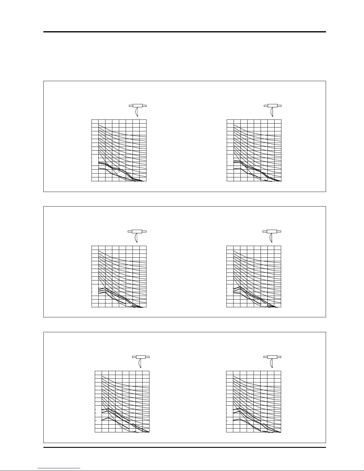
51
CHAPTER 4 ● Characteristics
5. NC Curves (LGH-RX3 Series)
● Ceiling embedded-type
LGH-15RX3
Background noise : 25 dB or less (A range) Background noise : 25 dB or less (A range)
Measurement site : Anechoic chamber Measurement site : Anechoic chamber
Operation conditions : Lossnay ventilation Operation conditions : Lossnay ventilation
90
85
80
75
70
65
60
55
50
45
40
35
30
25
20
15
10
62.5 125 500250 1000 2000 4000 8000
Overall
Octave band frequency near center (Hz)
Octave band sound pressure level (dB)
NC-70
NC-60
NC-50
NC-40
NC-30
Low
High
Extra
high
Low
90
85
80
75
70
65
60
55
50
45
40
35
30
25
20
15
10
62.5 125 250 500 1000 2000 4000 8000
Overall
Octave band frequency near center (Hz)
Octave band sound pressure level (dB)
NC-70
NC-10
NC-60
NC-50
NC-40
NC-30
1.5 m below
Measurement point
1.5 m below
Measurement point
NC-10
NC-20NC-20
High
Extra
high
LGH-20RX3
Background noise : 25 dB or less (A range) Background noise : 25 dB or less (A range)
Measurement site : Anechoic chamber Measurement site : Anechoic chamber
Operation conditions : Lossnay ventilation Operation conditions : Lossnay ventilation
LGH-35RX3
Background noise : 25 dB or less (A range) Background noise : 25 dB or less (A range)
Measurement site : Anechoic chamber Measurement site : Anechoic chamber
Operation conditions : Lossnay ventilation Operation conditions : Lossnay ventilation
90
85
80
75
70
65
60
55
50
45
40
35
30
25
20
15
10
62.5 125 250 500 1000 2000 4000 8000
NC-20
Overall
Octave band frequency near center (Hz)
Octave band sound pressure level (dB)
NC-70
NC-60
NC-50
NC-40
NC-30
90
85
80
75
70
65
60
55
50
45
40
35
30
25
20
15
10
62.5 125 250 500 1000 2000 4000 8000
Overall
Octave band frequency near center (Hz)
Octave band sound pressure level (dB)
NC-70
NC-60
NC-50
NC-40
NC-30
NC-10 NC-10
NC-20
1.5 m below
Measurement point
1.5 m below
Measurement point
Low
High
Extra
high
Low
High
Extra
high
90
85
80
75
70
65
60
55
50
45
40
35
30
25
20
15
10
62.5 125 250 500 1000 2000 4000 8000
Overall
Octave band frequency near center (Hz)
Octave band sound pressure level (dB)
NC-70
NC-10
NC-60
NC-50
NC-40
NC-30
90
85
80
75
70
65
60
55
50
45
40
35
30
25
20
15
10
62.5 125 250 500 1000 2000 4000 8000
NC-20
Overall
Octave band frequency near center (Hz)
Octave band sound pressure level (dB)
NC-70
NC-10
NC-60
NC-50
NC-40
NC-30
NC-20
1.5 m below
Measurement point
1.5 m below
Measurement point
Low
High
Extra
high
Low
High
Extra
high
Page 55
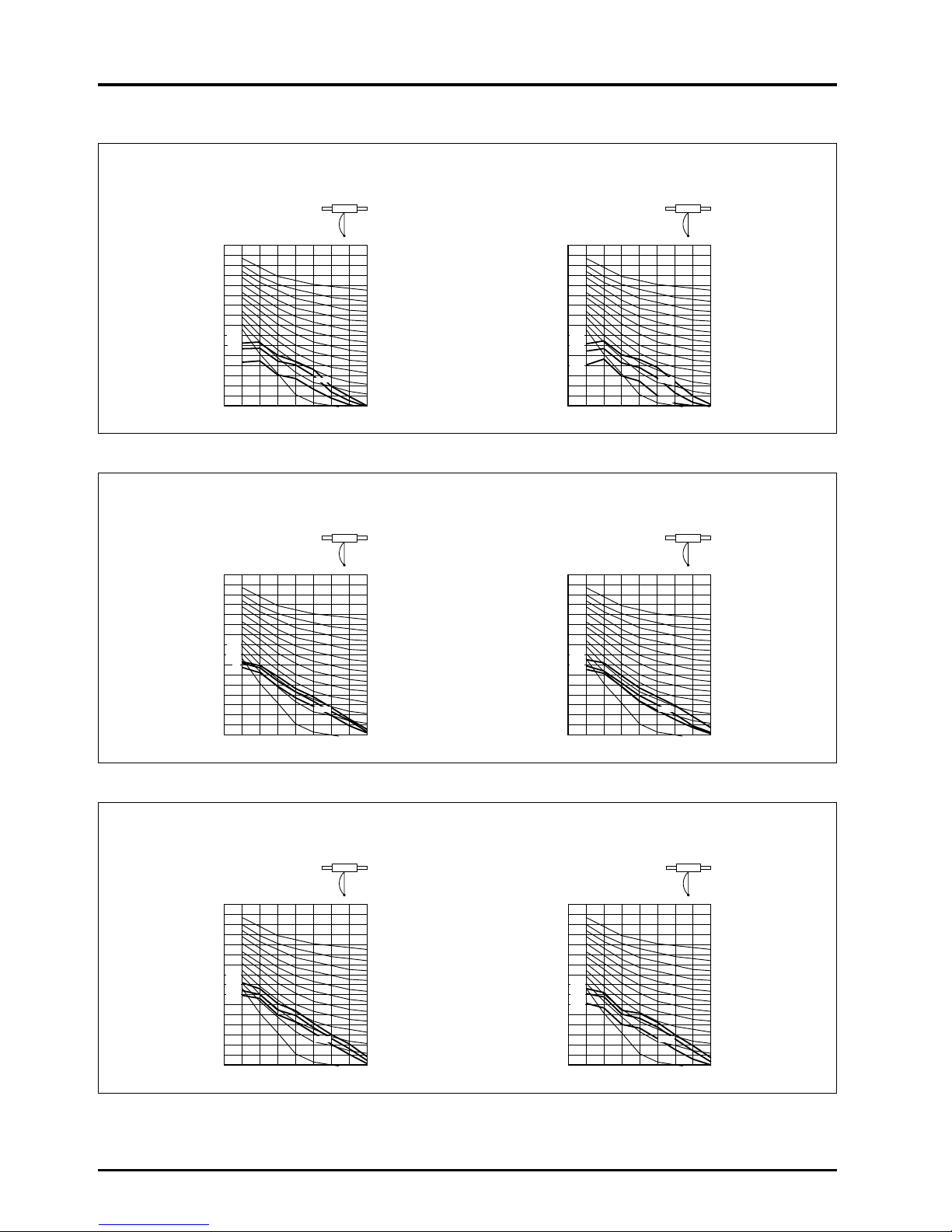
52
CHAPTER 4 ● Characteristics
90
85
80
75
70
65
60
55
50
45
40
35
30
25
20
15
10
62.5 125 250 500 1000 2000 4000 8000
Overall
Octave band frequency near center (Hz)
Octave band sound pressure level (dB)
NC-70
NC-10
NC-60
NC-50
NC-40
NC-30
90
85
80
75
70
65
60
55
50
45
40
35
30
25
20
15
10
62.5 125 250 500 1000 2000 4000 8000
NC-20
Overall
Octave band frequency near center (Hz)
Octave band sound pressure level (dB)
NC-70
NC-10
NC-60
NC-50
NC-40
NC-30
NC-20
1.5 m below
Measurement point
1.5 m below
Measurement point
Low
High
Extra
high
Low
High
Extra
high
90
NC-20
NC-70
NC-10
NC-60
NC-50
NC-40
NC-30
NC-20
NC-70
NC-10
NC-60
NC-50
NC-40
NC-30
85
80
75
70
65
60
55
50
45
40
35
30
25
20
15
10
62.5 125 250 500 1000 2000 4000 8000
Overall
Octave band frequency near center (Hz)
Octave band sound pressure level (dB)
90
85
80
75
70
65
60
55
50
45
40
35
30
25
20
15
10
62.5 125 250 500 1000 2000 4000 8000
Octave band frequency near center (Hz)
Octave band sound pressure level (dB)
1.5 m below
Measurement point
1.5 m below
Measurement point
Low
High
Extra
high
Low
High
Extra
high
90
NC-20
NC-70
NC-10
NC-60
NC-50
NC-40
NC-30
NC-20
NC-70
NC-10
NC-60
NC-50
NC-40
NC-30
85
80
75
70
65
60
55
50
45
40
35
30
25
20
15
10
62.5 125 250 500 1000 2000 4000 8000
Overall
Octave band frequency near center (Hz)
Octave band sound pressure level (dB)
90
85
80
75
70
65
60
55
50
45
40
35
30
25
20
15
10
62.5 125 250 500 1000 2000 4000 8000
Overall
Octave band frequency near center (Hz)
Octave band sound pressure level (dB)
1.5 m below 1.5 m below
Measurement point
Low
High
Extra
high
Low
High
Extra
high
LGH-50RX3
Background noise : 25 dB or less (A range) Background noise : 25 dB or less (A range)
Measurement site : Anechoic chamber Measurement site : Anechoic chamber
Operation conditions : Lossnay ventilation Operation conditions : Lossnay ventilation
LGH-80RX3
Background noise : 25 dB or less (A range) Background noise : 25 dB or less (A range)
Measurement site : Anechoic chamber Measurement site : Anechoic chamber
Operation conditions : Lossnay ventilation Operation conditions : Lossnay ventilation
LGH-100RX3
Background noise : 25 dB or less (A range) Background noise : 25 dB or less (A range)
Measurement site : Anechoic chamber Measurement site : Anechoic chamber
Operation conditions : Lossnay ventilation Operation conditions : Lossnay ventilation
Page 56
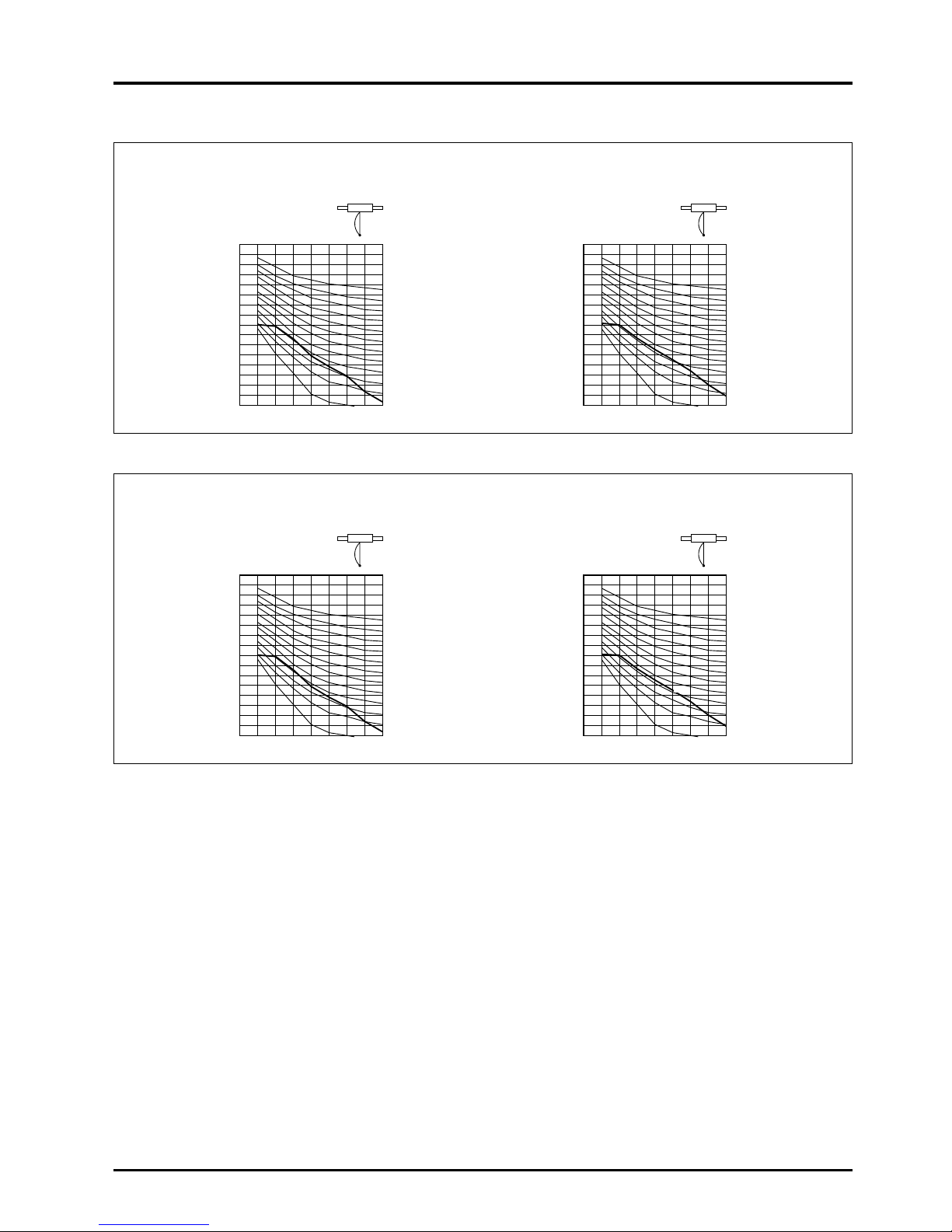
53
CHAPTER 4 ● Characteristics
90
85
80
75
70
65
60
55
50
45
40
35
30
25
20
15
10
62.5 125 250 500 1000 2000 4000 8000
NC-20
Overall
Octave band frequency near center (Hz)
Octave band sound pressure level (dB)
NC-70
NC-10
NC-60
NC-50
NC-40
NC-30
90
85
80
75
70
65
60
55
50
45
40
35
30
25
20
15
10
62.5 125 250 500 1000 2000 4000 8000
NC-20
Overall
Octave band frequency near center (Hz)
Octave band sound pressure level (dB)
NC-70
NC-10
NC-60
NC-50
NC-40
NC-30
1.5 m below
Measurement point
1.5 m below
Measurement point
90
85
80
75
70
65
60
55
50
45
40
35
30
25
20
15
10
62.5 125 250 500 1000 2000 4000 8000
NC-20
Overall
Octave band frequency near center (Hz)
Octave band sound pressure level (dB)
NC-70
NC-10
NC-60
NC-50
NC-40
NC-30
90
85
80
75
70
65
60
55
50
45
40
35
30
25
20
15
10
62.5 125 250 500 1000 2000 4000 8000
NC-20
Overall
Octave band frequency near center (Hz)
Octave band sound pressure level (dB)
NC-70
NC-10
NC-60
NC-50
NC-40
NC-30
1.5 m below
Measurement point
1.5 m below
Measurement point
LGH-200RX3
Background noise : 25 dB or less (A range) Background noise : 25 dB or less (A range)
Measurement site : Anechoic chamber Measurement site : Anechoic chamber
Operation conditions : Lossnay ventilation Operation conditions : Lossnay ventilation
LGH-150RX3
Background noise : 25 dB or less (A range) Background noise : 25 dB or less (A range)
Measurement site : Anechoic chamber Measurement site : Anechoic chamber
Operation conditions : Lossnay ventilation Operation conditions : Lossnay ventilation
Page 57

54
CHAPTER 4 ● Characteristics
90
85
80
75
70
65
60
55
50
45
40
35
30
25
20
15
10
62.5 125 250 500 1000 2000 4000 8000
NC-20
Overall
Octave band frequency near center (Hz)
Octave band sound pressure level (dB)
NC-70
NC-10
NC-60
NC-50
NC-40
NC-30
90
85
80
75
70
65
60
55
50
45
40
35
30
25
20
15
10
62.5 125 250 500 1000 2000 4000 8000
NC-20
Overall
Octave band frequency near center (Hz)
Octave band sound pressure level (dB)
NC-70
NC-10
NC-60
NC-50
NC-40
NC-30
90
85
80
75
70
65
60
55
50
45
40
35
30
25
20
15
10
62.5 125 250 500 1000 2000 4000 8000
NC-20
Overall
Octave band frequency near center (Hz)
Octave band sound pressure level (dB)
NC-70
NC-10
NC-60
NC-50
NC-40
NC-30
90
85
80
75
70
65
60
55
50
45
40
35
30
25
20
15
10
62.5 125 250 500 1000 2000 4000 8000
NC-20
Overall
Octave band frequency near center (Hz)
Octave band sound pressure level (dB)
NC-70
NC-10
NC-60
NC-50
NC-40
NC-30
90
85
80
75
70
65
60
55
50
45
40
35
30
25
20
15
10
62.5 125 250 500 1000 2000 4000 8000
NC-20
Overall
Octave band frequency near center (Hz)
Octave band sound pressure level (dB)
NC-70
NC-10
NC-60
NC-50
NC-40
NC-30
● Lossnay Pack-type for Buildings
LP-200B LP-350B
Background noise : 51 dB (A range) Background noise : 51 dB (A range)
Measurement site : Fan test operation site Measurement site : Fan test operation site
Measurement position : 1.5 m from the front center of the Measurement position : 1.5 m from the front center of the
unit, 1 m above the floor unit, 1 m above the floor
Operation conditions : Lossnay ventilation Operation conditions : Lossnay ventilation
LP-500B LP-750B
Background noise : 51 dB (A range) Background noise : 51 dB (A range)
Measurement site : Fan test operation site Measurement site : Fan test operation site
Measurement position : 1.5 m from the front center of the Measurement position : 1.5 m from the front center of the
unit, 1 m above the floor unit, 1 m above the floor
Operation conditions : Lossnay ventilation Operation conditions : Lossnay ventilation
LP-1000B
Background noise : 51 dB (A range)
Measurement site : Fan test operation site
Measurement position : 1.5 m from the front center of the
unit, 1 m above the floor
Operation conditions : Lossnay ventilation
Page 58

55
CHAPTER 4 ● Characteristics
Extra-
high
Air volume (m
3
/h)
High
Low
Installa-
tion site
Independent dispersed installationMachine room installation
Building
example
Application site
example
Applicable
No. of
people
Application
Type
Vertical-
type
Horizon
tal-type
6. List of Models
6.1 Model specifications
Ceiling
embedded-type
Ceiling exposed-
type
Lossnay Pack
Lossnay
Unit
Moisture resistant
LGH-15RX3
LGH-25RX3
LGH-35RX3
LGH-50RX
3
LGH-80RX3
LGH-100RX3
-50 / 60
LGH-150RX
3
LGH-200RX3
-50 / 60
LGH-50E5LP-200B
LP-350B
LP-500B
LP-750B
LP-1000B
LUT-
2302 - 2308
LUT-
3002 - 3008
LU-80,160,500
LU-1602 - 1606
LU-502 - 505
LUP-80, 160, 500
LU-
1602 - 1606
LUP-
502 - 505
150/150
250/250
350/350
500/500
800/800
1,000/1,000
1,500/1,500
2,000/2,000
—
1,000 - 2,900
2,000 - 5,000
4,000 - 7,000
4,000 - 10,000
6,000 - 13,000
2,000 - 28,000
3,000 - 36,000
300 - 7,000
1,200 - 13,200
4,000 - 35,000
500 - 6,000
1,600 - 14,400
4,000 - 35,000
150/150
250/250
350/350
500/500
800/800
1,000/1,000
1,500/1,500
2,000/2,000
490/480
120/110
180/160
230/210
350/300
670/660
870/720
1,340/1,320
1,740/1,440
300/260
Single-phase 220 to
240 V / 50 Hz
200V / 60Hz
Same as above
Same as above
Same as above
Same as above
Same as above
Same as above
Same as above
Single-phase
50/60Hz
Three-phase
50 or 60 Hz
Same as above
Same as above
Same as above
Same as above
—
—
———
—
—
—
ø100
ø150
ø150
ø200
ø250
ø250
ø350
ø350
ø200 or
210 × 590
250 × 350
325 × 400
405 × 500
405 × 540
1200 × 540
405 × 540
1200 × 540
—
—
———
—
—
—
Government
agency, office
building, tenant
building, hospital,
school, welfare
facility, shop,
hotel
School, shop,
welfare facility, hall
Government
agency, office
building, hospital,
welfare facility,
hall, shop, school,
hotel
Government
agency, office
building, hospital,
welfare facility,
hall, shop, school,
hotel
Hotel, pension,
welfare facility,
sports facility,
factory
Office,
conference room,
salon, board
room, hall, clinic
room, etc.
Office, conference
room, etc.
Office, conference
room, hall
Office, conference
room, hall, library
Office, hall, library,
pachinko parlour
Office, theatre, library,
pachinko parlour
Office, theatre
Office,
conference room,
hall, library,
pachinko parlour,
theatre
Large bath,
heated pool,
drying equipment
5 - 8
8 - 13
11 - 18
16 - 25
26 - 40
33 - 50
50 - 75
66 - 100
16 - 25
40 - 145
80 - 250
160 - 350
160 - 500
240 - 650
185 - 920
240 - 1200
30 - 250
130 - 480
400 - 1250
—
—
—
Model Power supply
Connection
duct diameter
or embedded
dimensions
Industrial <Lossnay>Building <Lossnay>
Industrial
<Lossnay>
Page 59

56
CHAPTER 4 ● Characteristics
Blades
Colour
6.2 List of material colours for Industrial Lossnay
Model
LGH-15RX
3
LGH-25RX3
LGH-35RX3
LGH-50RX3
LGH-80RX3LGH-100RX3
LGH-150RX3
LGH-200RX3
LGH-50E5
Colour Munsell
symbol
—
—
—
—
—
—
—
—
5Y 8.5/1
Mitsubishi
colour No.
—
—
—
—
—
—
—
—
Y-62
Material
Molten galvanized
steel plate
Molten galvanized
steel plate
Molten galvanized
steel plate
Molten galvanized
steel plate
Molten galvanized
steel plate
Molten galvanized
steel plate
Molten galvanized
steel plate
Molten galvanized
steel plate
Steel plate
Paint
specifications
—
—
—
—
—
—
—
—
Melamine
baked finish
Material
Incombustible
treated paper
Incombustible
treated paper
Incombustible
treated paper
Incombustible
treated paper
Incombustible
treated paper
Incombustible
treated paper
Incombustible
treated paper
Incombustible
treated paper
Incombustible
treated paper
Dimensions Weight
without frame with frame/unit
145 × 145 × 546
1.7 kg
171 × 171 × 322
1.2 kg
198 × 198 × 387
2.0 kg
198 × 198 × 458
2.3 kg
267 × 267 × 440
3.8 kg
267 × 267 × 553
4.8 kg
267 × 267 × 440
3.8 kg
267 × 267 × 553
4.8 kg
178 × 198 × 1,129
8.0 kg
Q’ty
1
2
2
2
2
2
4
4
1
Humidifying
method
—
—
—
—
—
—
—
—
—
Dimensions
—
—
—
—
—
—
—
—
—
Q’ty
—
—
—
—
—
—
—
—
—
Outside
Heat recovery unit
Humidifier
Model
LGH-15RX
3
-E
LGH-25RX
3
-E
LGH-35RX
3
-E
LGH-50RX
3
-E
LGH-80RX
3
-E
LGH-100RX
3
-E
LGH-150RX
3
-E
LGH-200RX
3
-E
LGH-50E
5
Material
Shape,
diameter
ABS resin
Centrifugal fan
ø180
ABS resin
Centrifugal fan
ø180
ABS resin
Centrifugal fan
ø220
ABS resin
Centrifugal fan
ø220
Steel plate
Centrifugal fan
ø245
Steel plate
Centrifugal fan
ø245
Steel plate
Centrifugal fan
ø245
Steel plate
Centrifugal fan
ø245
ABS resin
Centrifugal fan
ø200
Material
Prefilter
NP/400
Prefilter
NP/400
Prefilter
NP/400
Prefilter
NP/400
Prefilter
NP/400
Prefilter
NP/400
Prefilter
NP/400
Prefilter
NP/400
Prefilter
NP/400
Dimensions
552
×
125
×
15
658
×
151
×
15
789
×
175
×
15
931
×
178
×
15
895
×
238
×
15
1,122 × 238 × 15
895
×
238
×
15
1,122 × 238 × 15
(Intake side)
1,129
× 200 × 15
(Exhaust side)
376 × 143 × 14
Filtering
efficiency
Gravitational
method 82%
Gravitational
method 82%
Gravitational
method 82%
Gravitational
method 82%
Gravitational
method 82%
Gravitational
method 82%
Gravitational
method 82%
Gravitational
method 82%
Gravitational
method 82%
Material
Self-extinguishing
urethane foam
Self-extinguishing
urethane foam
Self-extinguishing
urethane foam
Self-extinguishing
urethane foam
Self-extinguishing
urethane foam
Self-extinguishing
urethane foam
Self-extinguishing
urethane foam
Self-extinguishing
urethane foam
Self-extinguishing
urethane foam
Ambient
temperature
-10°C to +40°C
RH80% or less
-10°C to +40°C
RH80% or less
-10°C to +40°C
RH80% or less
-10°C to +40°C
RH80% or less
-10°C to +40°C
RH80% or less
-10°C to +40°C
RH80% or less
-10°C to +40°C
RH80% or less
-10°C to +40°C
RH80% or less
-10°C to +40°C
RH80% or less
Exhaust air
conditions (RA)
-10°C to +40°C
RH80% or less
-10°C to +40°C
RH80% or less
-10°C to +40°C
RH80% or less
-10°C to +40°C
RH80% or less
-10°C to +40°C
RH80% or less
-10°C to +40°C
RH80% or less
-10°C to +40°C
RH80% or less
-10°C to +40°C
RH80% or less
-10°C to +40°C
RH80% or less
Supply air
conditions (OA)
-10(-15)°C to +40°C
RH80% or less
-10(-15)°C to +40°C
RH80% or less
-10(-15)°C to +40°C
RH80% or less
-10(-15)°C to +40°C
RH80% or less
-10(-15)°C to +40°C
RH80% or less
-10(-15)°C to +40°C
RH80% or less
-10(-15)°C to +40°C
RH80% or less
-10(-15)°C to +40°C
RH80% or less
-10(-15)°C to +40°C
RH80% or less
Q’ty
2
2
2
2
2
2
4
4
1
3
Filter
Insulation material
Product usage conditions
Page 60

57
CHAPTER 4 ● Characteristics
Material
Self-extinguishing urethane foam
Self-extinguishing urethane foam
Self-extinguishing urethane foam
Self-extinguishing urethane foam
Self-extinguishing urethane foam
Insulation material
Product usage conditions
(Ambient temperature, exhaust
air, supply air conditions)
Product usage conditions
(Ambient temperature, exhaust
air, supply air conditions)
Suction method
Single-side suction
Single-side suction
Single-side suction
Double-side suction
Double-side suction
Q’ty
2
3
4
6
8
Heat recovery unit
6.3 List of material colours for Building Lossnay
Model
LP-200B
LP-350B
LP-500B
LP-750B
LP-1000B
Model
LP-200B
LP-350B
LP-500B
LP-750B
LP-1000B
Model
LUT-2302
LUT-2303
LUT-3002
LUT-3003
LU-80
LU-160
LU-500
LUP-80
LUP-160
LUP-500
LSM-150
Colour Munsell
symbol
5Y 6.5/1
5Y 6.5/1
5Y 6.5/1
5Y 6.5/1
5Y 6.5/1
5Y 6.5/1
5Y 6.5/1
5Y 6.5/1
5Y 6.5/1
5Y 6.5/1
7.5BG 6/1.5
Mitsubishi
colour No.
N-E6
N-E6
N-E6
N-E6
N-E6
N-E6
N-E6
N-E6
N-E6
N-E6
B-8001
Material
Steel plate Thickness: 1.6 t
Steel plate Thickness: 1.6 t
Steel plate Thickness: 1.6 t
Steel plate Thickness: 1.6 t
Steel plate Thickness: 1.2 t
Steel plate Thickness: 1.2 t
Steel plate Thickness: 1.6 t
Steel plate Thickness: 1.2 t
Steel plate Thickness: 1.2 t
Steel plate Thickness: 1.6 t
Steel plate Thickness: 1.2 t
Paint specifications
Polyester powder
Polyester powder
Polyester powder
Polyester powder
Polyester powder
Polyester powder
Polyester powder
Polyester powder
Polyester powder
Polyester powder
Melamine baked finish
Material
Incombustible treated paper
Incombustible treated paper
Incombustible treated paper
Incombustible treated paper
Incombustible treated paper
Incombustible treated paper
Incombustible treated paper
Polypropylene resin
Polypropylene resin
Polypropylene resin
Aluminum
Dimensions
without frame
299.5 × 742
299.5 × 742
299.5 × 742
299.5 × 742
300 × 488
300 × 488
550 × 487
300 × 489
300 × 489
550 × 495
300 × 481.8
Weight with
frame/unit
19.2 kg
19.2 kg
19.2 kg
19.2 kg
8 kg
8 kg
22 kg
21 kg
21 kg
32 kg
25 kg
Q’ty
6
9
8
12
2
4
4
2
4
4
2
Material
Self-extinguishing urethane foam
Self-extinguishing urethane foam
Self-extinguishing urethane foam
Self-extinguishing urethane foam
Self-extinguishing urethane foam
Self-extinguishing urethane foam
Self-extinguishing urethane foam
———
—
-10°C to +50°C RH80% or less
-10°C to +50°C RH80% or less
-10°C to +50°C RH80% or less
-10°C to +50°C RH80% or less
-10°C to +50°C RH80% or less
-10°C to +50°C RH80% or less
-10°C to +50°C RH80% or less
-10°C to +80°C RH100%
-10°C to +80°C RH100%
-10°C to +80°C RH100%
-10°C to +160°C RH100%
Blade
diameter
#1 1/2#2#2 1/2
#2
#2
Drive
method
Belt
Belt
Belt
Belt
Belt
Blade
shape
Centrifugal fan
Centrifugal fan
Centrifugal fan
Centrifugal fan
Centrifugal fan
Material
Prefilter NP/400
Prefilter NP/400
Prefilter NP/400
Prefilter NP/400
Prefilter NP/400
Dimensions
505 × 531 × 20
505 × 531 × 20
505 × 531 × 20
505 × 531 × 20
505 × 531 × 20
Q’ty
4
6
8
12
16
Filtering efficiency
Gravitational method 85%
Gravitational method 85%
Gravitational method 85%
Gravitational method 85%
Gravitational method 85%
-10°C to +40°C RH80% or less
-10°C to +40°C RH80% or less
-10°C to +40°C RH80% or less
-10°C to +40°C RH80% or less
-10°C to +40°C RH80% or less
Colour Munsell
symbol
5Y 6.5/1
5Y 6.5/1
5Y 6.5/1
5Y 6.5/1
5Y 6.5/1
Mitsubishi
colour No.
N-E6
N-E6
N-E6
N-E6
N-E6
Material
Steel plate Thickness: 1.6 t
Steel plate Thickness: 1.6 t
Steel plate Thickness: 1.6 t
Steel plate Thickness: 1.6 t
Steel plate Thickness: 1.6 t
Paint
specifications
Polyester powder
Polyester powder
Polyester powder
Polyester powder
Polyester powder
Material
Incombustible treated paper
Incombustible treated paper
Incombustible treated paper
Incombustible treated paper
Incombustible treated paper
Dimensions
without frame
550 × 487
550 × 487
550 × 487
550 × 487
550 × 487
Weight with
frame/unit
22 kg
22 kg
22 kg
22 kg
22 kg
Colour
Outside
FilterAir-supply fan
Insulation materialHeat recovery unit
OutsideColour
Page 61

58
CHAPTER 4 ● Characteristics
6.4 List of industrial/business Lossnay accessories
Model
LGH-15RX
3
LGH-25RX3
LGH-35RX
3
LGH-50RX
3
LGH-80RX
3
LGH-100RX3
LGH-150RX3
LGH-200RX3
LGH-50E5
LP-200B
LP-350B
LP-500B
LP-750B
LP-1000B
LUT-2302, 2303
LUT-3002, 3003
Accessories
● Duct connection flanges . . . . . . . . × 4
● Mounting screws . . . . . . . . . . . . . × 34
● Washers . . . . . . . . . . . . . . . . . . . × 32
● Protective cover . . . . . . . . . . . . . . × 1 <For installing upside down>
● Lossnay connection cable . . . . . . . × 1
● IB . . . . . . . . . . . × 1
● IM . . . . . . . . . . . × 1
● Mounting screws . . . . . . . . . . . . . × 18
● Duct connection flange . . . . . . . . . × 4 <double flanges at SA and EA sides>
● Protective cover . . . . . . . . . . . . . . × 1 <For installing upside down>
● Lossnay connection cable . . . . . . . × 1
● IB . . . . . . . . . . . × 1
● IM . . . . . . . . . . . × 1
Round duct connection flange: 2, slave unit fixing plate: 1
Touch-up paint
Touch-up paint
Touch-up paint
Touch-up paint, M6 nut: 6, M6 washer: 6
Touch-up paint, M6 nut: 6, M6 washer: 6
Upper connection fitting: 2, lower connection fitting: 2,
M8 screw: 8, M10 screw: 4, M10 washer: 4, packing: 3
Upper connection fitting: 2, lower connection fitting: 2,
M8 screw: 8, M10 screw: 4, M10 washer: 4, packing: 3
Duct packaging site
EA RA
OA SA
EA RA
OA SA
EA RA
OA SA
* Top view. There
is a space
between the EA
side and the OA
side.
* Top view. One is
inserted at each
opening in the
opposite
direction.
* Top view.
2 are inserted on
top of each other
at the SA and EA
openings, in the
opposite direction.
Page 62

CHAPTER 5
System Design Recommendations
Page 63

60
CHAPTER 5 ● System Design Recommendations
1. Lossnay Usage Conditions
Main unit installation conditions Outdoor air and exhaust air conditions
Commercial-use Lossnay -10°C to +40°C, RH80% or less -10°C to + 40°C, RH80% or less.
Same as left
LP model Lossnays -10°C to +40°C, RH80% or less The room air temperature/humidity is controlled
by separate devices.
LU, LUT model Lossnays -10°C to +50°C, RH80% or less Same as left
LUP model Lossnay -10°C to +80°C, RH100% Same as left
Facility Lossnay
In some cases special attention needs to be paid to extreme operating conditions.
These are described as below:
1.1 Use in cold climates (outdoor temperature: –5°C or less)
Plot the Lossnay intake air conditions A and B on a psychrometric
chart as shown on the right. If the high temperature side air B
intersects the saturation curve such as at C, moisture
condensation or frosting will occur on the Lossnay. In this case,
the low temperature side air A should be preheated to the
temperature indicated by point A’ so that point C shifts to the point
C’.
1.2 Use in high humidity conditions (Relative humidity: 80% or more)
When using the system in high humidity conditions such as heated pools, bathrooms, mushroom cultivation houses, etc.,
moisture will condense inside the Core, and drainage will occur. In these cases, the general purpose Lossnay that uses
treated paper cannot be used. Instead the moisture resistant Lossnay must be used.
The following moisture resistant Lossnay models are available. The usage conditions differ so select the model according to
the application.
●
Total moisture resistant-type (Relative humidity for both installation site and supply/exhaust conditions can be 100%)
LUP series (sensible heat exchange-type with independent Lossnay Core)
1.3 Use in other special conditions
A
A’
C’
C
B
Saturation curve
Dry bulb temperature (°C)
Absolute humidity (kg/kg’)
●
The Lossnay cannot be used where toxic gases and corrosive element’s such as acids, alkalis, organic
solvents, oil mist or paints exist.
●
Use where heat is recovered from odor-laiden air and supplied to another place (area) is not possible.
●
Avoid use where salt or hot water damage may occur.
Page 64

61
CHAPTER 5 ● System Design Recommendations
2. Noise Value of Lossnay with Built-in Fans
The noise level specified for Lossnay units is as that measured in an anechoic chamber. The sound level may increase by 8 to
11 dB according to the installation construction material, and room contents.
When using the Lossnay in a quiet room, it is recommended that measures such as installing a muffling duct, optional silencer
intake/exhaust grill (PZ-FG type)* or silencer box (PZ-SB type)* be carried out.
* Please consult with nearest Lossnay supplier about availability of these parts.
3. Attachment of Air Filter
An air filter must be mounted to the air inlets (both intake and exhaust) of the Lossnay to clean the air and to prevent the Core
from clogging. Always mount this filter, and periodically service it.
4. Duct Construction
●
Always treat the two ducts on the outdoor side (outdoor air intake and exhaust outlet) with insulation to prevent frosting or
condensition.
●
The outdoor duct gradient must be 1/30 or more (to wall side) to prevent rain water from infiltrating the system.
●
Do not use the standard vent caps or round hoods where they may come into direct contact with rain water.
(Instead, use of a deep hood is recommended.)
5. By-pass Ventilation
Do not operate with “By-pass ventilation” when heating during winter. Frost or condensation may generate on the main unit
and cause discolouring of the ceiling, etc.
Page 65

6. Transmission Rate of Various Gases and Related Maximum
Workplace Concentration
62
CHAPTER 5 ● System Design Recommendations
Measurement
Air volume Exhaust air
Supply air
Transmission
Max. workplace
conditions
Gas ratio concentration concentration rate concentrations
Q
SA/QRA CRA (ppm) CSA (ppm) (%) (ppm)
Hydrogen fluoride 1.0 36 <0.5 - 0 0.6
Hydrogen chloride 1.0 42 <0.5 - 0 5
Nitric acid 1.0 20 <0.5 - 0 10
Sulfulic acid 1.0 2.6 mg/m
3
- 0 mg/m
3
- 0 0.25
Trichlene 1.0 85 2.5 2.9 200
Acetone 1.0 5 0.13 2.5 1,000
Xylene 1.0 110 2.5 2.3 150
Isopropyl alcohol 1.0 2,000 50 2.5 400
Methanol 1.0 41 1.0 2.4 200
Ethanol 1.0 35 1.0 2.9 1,000
Ethyl acetate
1.0 25 0.55 2.2 400
alcohol
Ammonia 1.0 70 2 2.9 50
Hydrogen sulfide 1.0 15 0.44 2.9 10
Carbon monoxide 1.0 71.2 0.7 1.0
Carbon dioxide 1.0 44,500 1,400 1.8
Smoke 1.0 ––1 - 2
Formaldehyde 1.0 0.5 0.01 2 0.08
Sulfur hexaflouride 1.0 27.1 0.56 2.1
Skatole 1.0 27.1 0.56 2.0
Indole 1.0 27.1 0.56 2.0
Toluene 1.0 6.1 0.14 2.3
Measurement method
• Chemical analysis
with colorimetric
method for
H2
SO4, HCHO
• Ultrasonic method
with
gas
concentration
device
for CO, SF
6
•
Infrared method
with gas
concentration
device for CO
2
•
Gas chromatography
for others
The fans are
positioned at the air
supply/exhaust
suction positions of
the element
Measurement
conditions:
27°C, 65% RH
* OA density for
CO
2 is 600 ppm.
CAUTION
The above does not apply to the moisture resistant total heat recovery unit.
Page 66
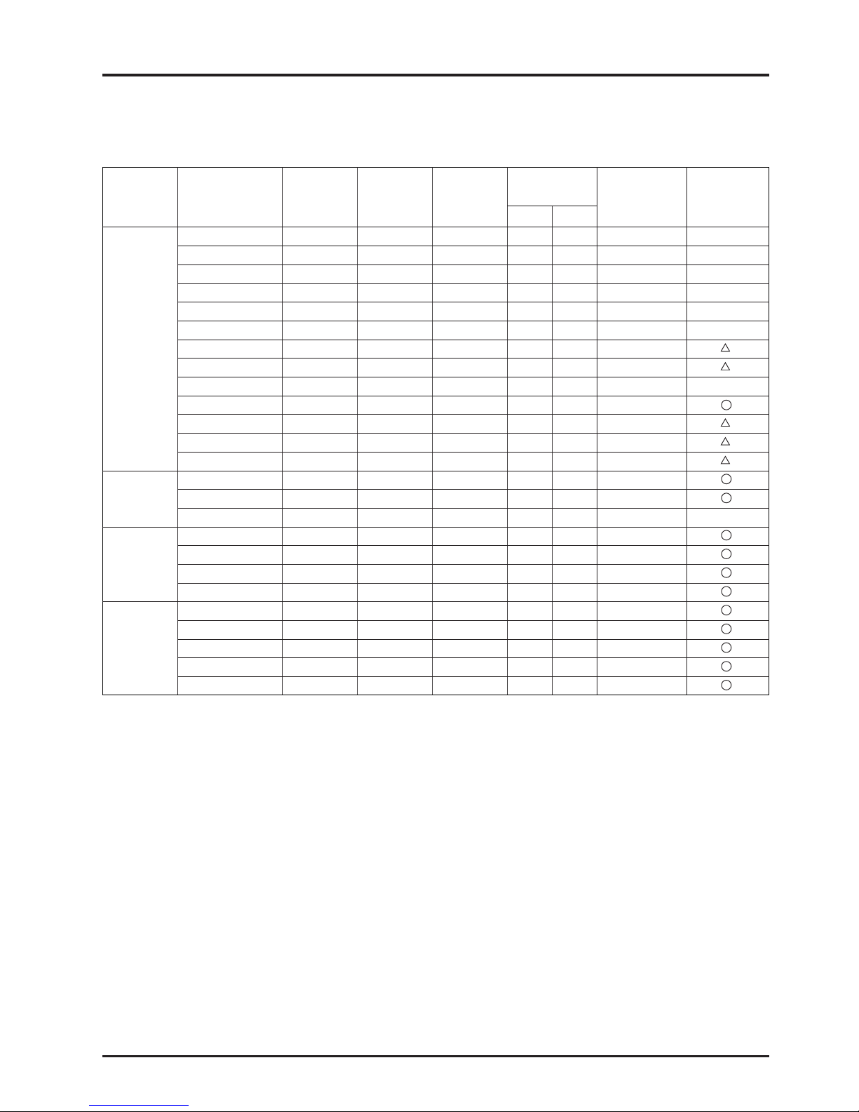
Main Molecular Gas Sulubility Max.
generation Gas name formula vapour
Non-toxic/
in water workplace
Useability
site mist odor
toxic/
concentration
of Lossnay
m /m
g/100g
Sulfuric acid H
2
SO4 Mist Found 2,380 0.25
×
Nitric acid HNO
3 Mist Found 180 10
×
Phosphoric acid H
3PO4 Mist Found 41 0.1
×
Acetic acid CH
3COOH Mist Bad odor 2,115 25
×
Chemical
Hydrogen chloride HCl Gas Found 427 58 5
×
plantor
Hydrogen fluoride HF Gas Found 90 0.6
×
chemical
Sulfur dioxide SO
2 Gas Found 32.8 0.25
laboratory
Hydrogen sulfide H
2S Gas Found 2.3 10
Ammonia NH
3 Gas Bad odor 635 40 50
×
Phosphine PH
3 Gas Found 0.26 0.1
Methanol CH
3OH Vapor Found Soluble 200
Ethanol CH
3CH2OH Vapor Found Soluble 1,000
Ketone Vapor Found Soluble 1,000
Skatole C
9H9N Gas Bad odor Minute
Toilet Indole C
9H7N Gas Bad odor Minute
Ammonia NH
3 Gas Bad odor 635 40 50 ×
Nitric monoxide NO 0.0043 50
Others
Ozone O
3 0.00139 0.1
Methane CH
4 0.0301
Chlorine Cl
2 Minute 0.5
Air Mixed gases Gas None 0.0167
Air
Oxygen O
2 Gas None 0.0283
(reference)
Nitrogen N
2 Gas None 0.0143
Carbon monoxide CO Gas Found 0.0214
Carbon dioxide CO
2 Gas None 0.759
RR
63
CHAPTER 5 ● System Design Recommendations
7. Solubility of Odors and Toxic Gases, etc., in Water and
Effect on Lossnay Core
Note: 1. Water soluble gases and mists cannot be used because the amount that is transmitted with the water is too great.
2. Acidic gases and mists cannot be used because these will accumulate in the Core and cause damage.
3. The above does not apply to the moisture resistant total heat recovery unit.
Page 67
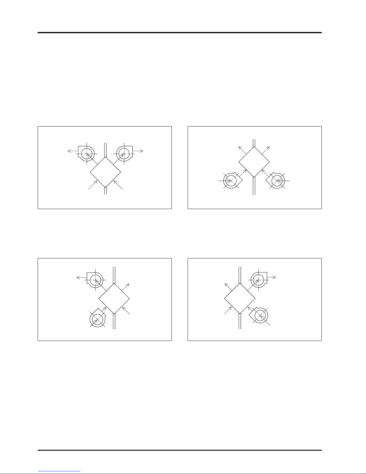
64
CHAPTER 5 ● System Design Recommendations
8.
Positioning of the Supply/Exhaust Fans and the Air Transmission
Rate (excluding moisture resistant total heat recovery units)
The following four methods can be used for when setting the Lossnay supply and exhaust fans around the Lossnay Core.
When using the LU and LUT models, methods a or b should be used in respect of both the Lossnay Core air leakage and
effective air ventilation. Use method c if air leakage to the RA or SA sides is not allowed such as in hospital air conditioning, or
transmission of the fan noise into the room must be suppressed by putting the Lossnay Core between the supply/exhaust fans
and room, and if a certain degree of air leakage is allowed between OA to EA.
a. Installing the supply fan (OA-SA) and exhaust fan b. Installing the supply fan (OA-SA) and exhaust fan
(RA-EA) for suction feed to the Lossnay Core (RA-EA) for forced supply to the Lossnay Core
If the static pressure difference between SA and RA and The air leakage rate is the same as in system a.
between EA and OA is 50mmAq, the air leakage rate will
be 2.5%, and 3.4%. This value is of no problem for most
standard uses.
c. Installing the supply fan (OA-SA) for force feed and d. Installing the supply fan (OA-SA) for suction feed
the exhaust fan (RA-EA) for suction feed and the exhaust fan (RA-EA) for force feed
Lossnay
EA
OA RA
SA
Lossnay
EA
OA RA
SA
In this case, the positive/negative relation of the static In this case, the intake side pressure (OA-SA) will be
pressure will be the reverse of that in system d, and the air negative, and the exhaust side pressure (RA-EA) will be
leakage outside the room (leakage from OA to EA) will be positive, so the amount of air leakage to the intake side will
the same as system d. Thus, the effective volume of be the greatest. If the static pressure difference between
ventilating air will be reduced by that rate. OA and RA is 50 mmAq, the air leakage rate will be 10.5%,
and 13.0%.
This system can be used when an air leakage of 10% to the
intake side (OA-SA) is permitted, but should be avoided in
all other cases.
Lossnay
EA
RA
OA
SA
Lossnay
EA
RA
OA
SA
Outdoors
Fan for exhaust air Fan for supply air
Indoors
Outdoors
Fan for exhaust air
Fan for supply air
Indoors Outdoors
Fan for supply air
Fan for exhaust air
Indoors
Outdoors
Fan for supply air Fan for exhaust air
Indoors
Page 68
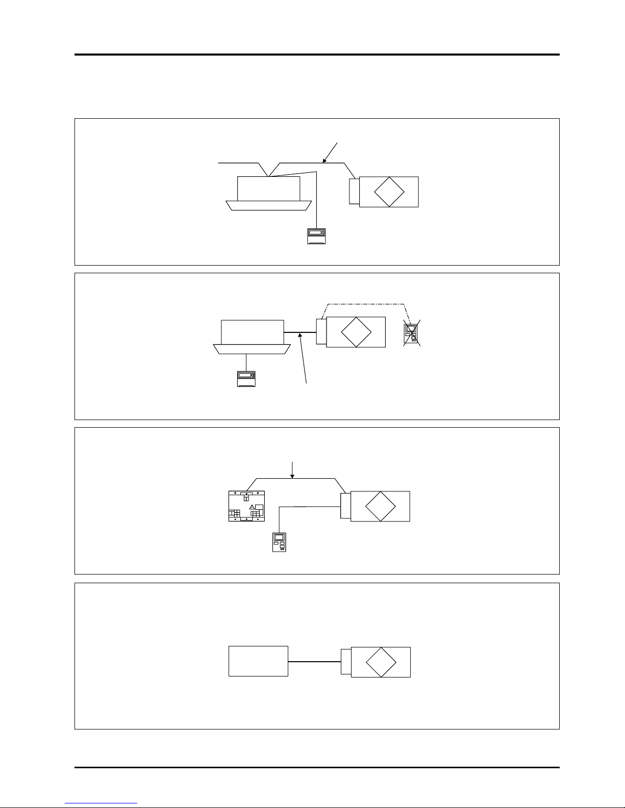
65
CHAPTER 5 ● System Design Recommendations
9. Combined Operation with other Air Conditioners
Connecting the Lossnay can configure the following system.
Interlocked with City Multi
Interlocked with Mr. Slim
Independent Lossnay Unit (Not interlocked with City Multi or Mr. Slim systems.)
Interlocked with external unit (BMS)
City Multi
indoor unit
Remote controller
M-NET transmission cable
Lossnay unit
LGH-**RX
3-E
Mr.Slim (A, K-control)
indoor unit
Lossnay unit
LGH-**RX
3-E
Lossnay remote controller
cannot be used.
Remote controller
Slim-Lossnay connecting cable
(Enclosed accessory)
Lossnay remote controller
M-NET transmission cable
Power supply unit
Lossnay unit
LGH-**RX3-E
Lossnay unit
LGH-**RX
3-E
EXT. signal source
for interlocking
to the Lossnay
Page 69

66
CHAPTER 5 ● System Design Recommendations
10. Automatic Ventilation Switching
Effect of Automatic Ventilation Mode
The automatic damper mode automatically provides the correct ventilation for the conditions in the room. It eliminates the need
for troublesome switch operations when setting the Lossnay ventilator to “By-pass” ventilation. The following shows the effect
“By-pass” ventilation will have under various conditions.
(1) Reduces cooling load
If the air outside is cooler than the air inside the building during the cooling season (such as early morning or at night),
“By-pass” ventilation will draw in the cooler outside air and reduce the cooling load on the system.
(2) Cooling using outdoor air
During cooler seasons (such as between spring and summer or between summer and fall), if the people in a room cause
the temperature of the room to rise, “By-pass” ventilation draw in the cool outside air and use it as is to cool the room.
(3) Night purge
“By-pass” ventilation can be used to release hot air from inside the building that has accumulated in buildings a business
district during the hot summer season.
(4) Office equipment room cooling
During cold season, outdoor air can be drawn in and used as is to cool rooms where the temperature has risen due to the
use of office equipment.
(Only when interlocked with City Multi and Mr. Slim indoor unit)
Page 70
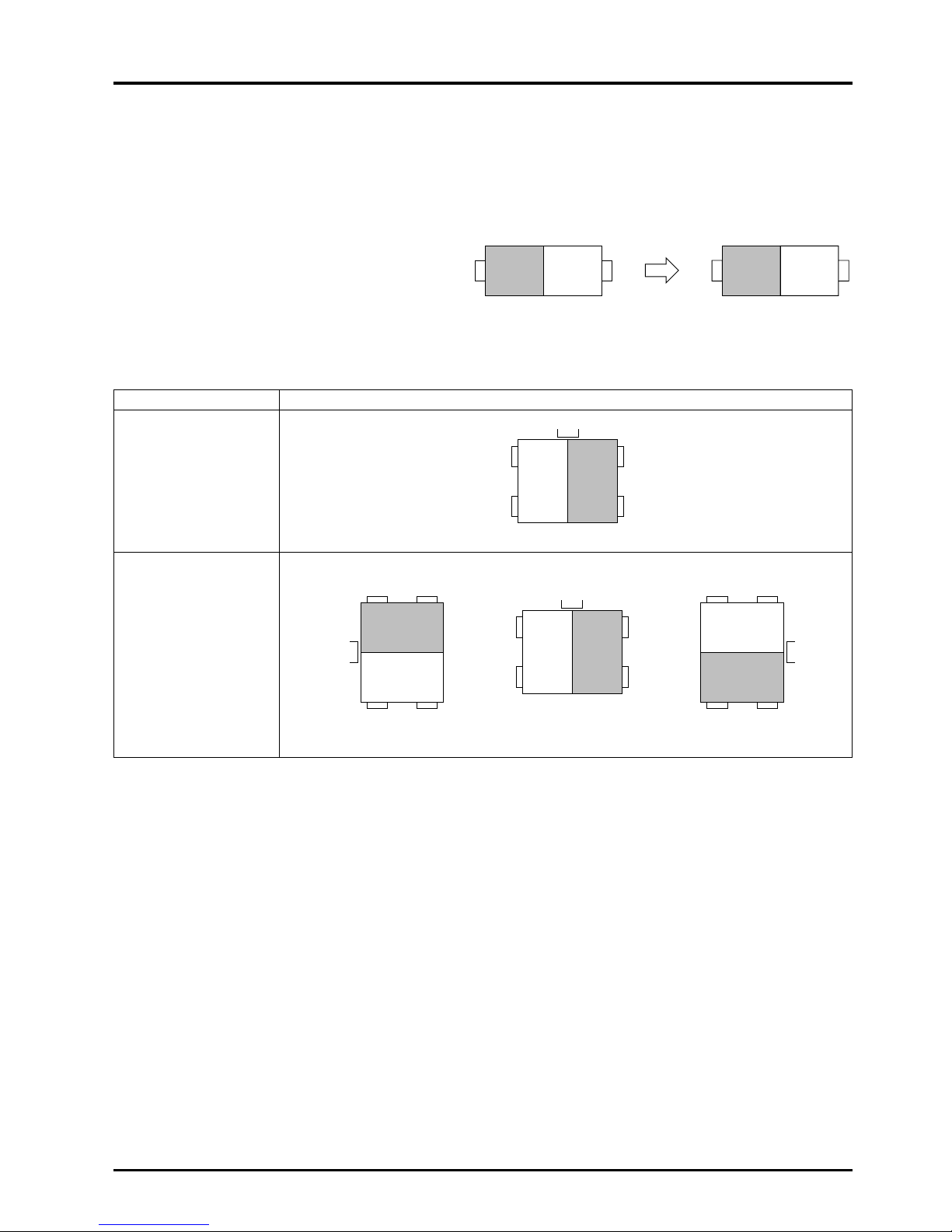
Model name Installation patterns
LGH-15RX
3
LGH-25RX3
LGH-35RX
3
LGH-50RX3
LGH-80RX3
LGH-100RX
3
SA OA
OA EA
EA OA
RA SA
SA
RA
OA
EA
SA
RA
OA
EA
67
CHAPTER 5 ● System Design Recommendations
11. Vertical Installation of LGH Series
Installation of ceiling embedded-type industrial Lossnay
11.1 Top/bottom reverse installation
All LGH-RX3 models can be installed in reverse.
11.2 Vertical installation
Vertical installation is possible, but the installation pattern is limited for some models. Refer to the following table for the
installation patterns.
To p
Bottom
To p
Bottom
To p
Bottom
To p
Bottom
To p
Bottom
Bottom
To p
(Precautions)
●
When constructing for vertical installation, make sure that rain water will not enter the Lossnay unit from outdoors.
●
Always transport the unit in the specified state. Vertical installation applies only to after installation, and does not apply to
transportation.
(The motor may be damaged if the unit is transported vertically.)
11.3 Slanted installation
Slanted installation is not possible.
Special note
The LGH-RX
3 model was conventionally designed for being embedded in the ceiling. If possible, vertical installation should be
avoided in regard to construction and maintenance.
Page 71
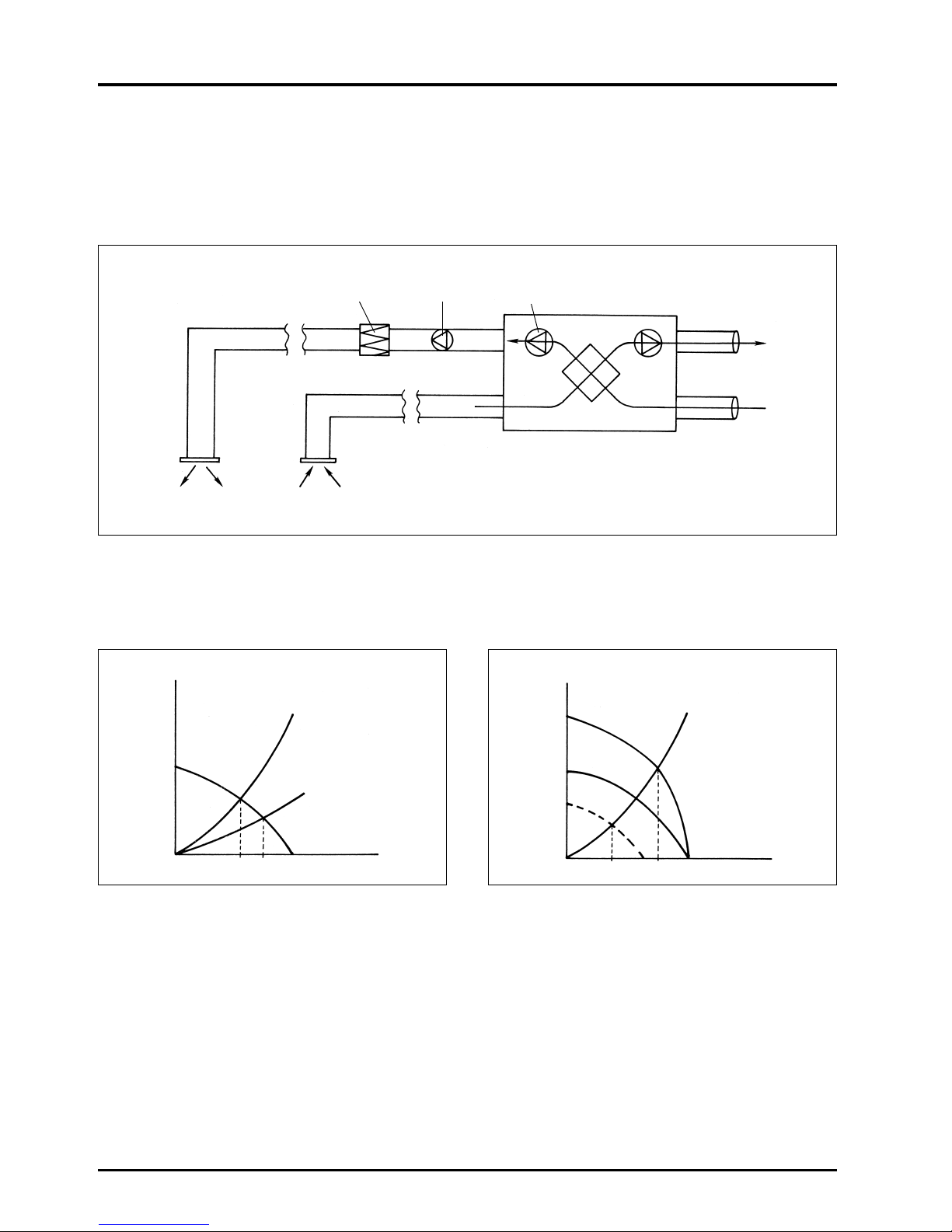
68
CHAPTER 5 ● System Design Recommendations
12. Installation of Supplementary Fan Devices After Lossnay
Unit
On occasions it may be necessary to install additional fans in the ductwork following the LGH type Lossnay. This is because of
the inclusion of extra components such as control dampers, high-efficiency filters, sound attenuators, etc. which create a
significant extra static pressure to the airflow. An example of such an installation is as shown below.
For such an installation care should be taken to avoid undue stress on the fan motors. Referring to the diagrams below, so
long as Q1’ ≥ Q2, there is no adverse effect on the motors. This is generally such in the majority of cases.
Q-H for Lossnay without extra fan Q-H for Lossnay with extra fan
Static pressure generating component Additional fan
EA
OA
Lossnay
Lossnay fan
SA RA
H
H
1
H
H
1
H
2
H1
+ H2
Q
1
Q
2
Q
1’
Q Lossnay
Lossnay with static pressure
increasing component.
Lossnay with static pressure
increasing component.
Lossnay
Q
Q
Page 72

CHAPTER 6
Examples of Lossnay Applications
Page 73

70
CHAPTER 6 ● Examples of Lossnay Applications
Lossnay ventilation systems are proposed for eight types of applications in this chapter. These systems are planned for
Japanese use, and actual systems will differ according to each country. These should be used only as reference.
1. Large Office Building
1.1 System plan points
Conventional central systems in large buildings, run in floor and building ducts, have generally been preferred to individual
room units. Thus, air conditioning and ventilation after working hours was not possible.
In this plan, an independent dispersed ventilation method has been applied to resolve this problem. Such a system’s main
advantage is that it allows 24-hour operation.
A package-type air conditioning unit is installed in the ceiling, and ventilation is performed with the ceiling-embedded-type
Lossnay. Ventilation in the toilet, kitchenette and lift halls, etc., is performed with a straight centrifugal fan.
Setting outline
●
Building form : Basement floor SRC (Slab Reinforced Concrete), 8 floors above ground S construction
Total floor space 30,350 m
2
●
Basement : Employee cafeteria
●
Ground floor : Lobby, conference room
●
2 to 7th floor : Offices, salons, board room
●
Air conditioning : Package air conditioning
●
Ventilation : Ceiling embedded-type Lossnay, straight centrifugal fan
1.2 Current topics
(1) Operation system that answers individual needs is required.
●
Free independent operation system
●
Simple control
(2) Effective use of floor space
(elimination of machine room)
(3) Application to Building Management Laws
●
Effective humidification
●
Elimination of indoor dust
(4) Energy conservation
1.3 Proposed details
(1) Air conditioning
●
In general offices, the duct method will be applied with
several ceiling-embedded multiple cooling heat pump
packages in each zone to allow total zone operation.
●
Board rooms, conference rooms and salons will be air
conditioned with a ceiling embedded-type or cassette-type
multiple cooling heat pump package in each room.
Installation state of office system air conditioning system
– The air supplied from the Lossnay is introduced into
the intake side of the air conditioner, and the room stale
air is directly removed from the inside of the ceiling.
Return grille
Grille
SA (Supply air)
Air conditioner
Air conditioner
Supply grille
RA (Return air)
SA (Supply air to room)
EA
(Exhaust
air)
OA
(Outdoor
air
suction)
EA
(Exhaust
air)
OA
(Outdoor
air
suction)
Suspension bolt
position
Suspension bolt
Inspection
space
Lossnay
Lossnay
Inspection
hole
Inspection hole
Page 74

71
CHAPTER 6 ● Examples of Lossnay Applications
(2) Ventilation
●
For general offices, a ceiling embedded-type Lossnay will be installed in the ceiling. The inside of the ceiling will be
used as a return chamber for exhaust, and the air from the Lossnay will be supplied to the air-conditioning return duct
and mixed with the air in the air conditioning passage. (Exhaust air is taken in from the entire area, and supply air is
introduced into the air conditioner to increase the ventilation effectiveness for large rooms.)
●
For board rooms, conference rooms and salons, a ceiling embedded-type Lossnay will be installed in the ceiling. The
stale air will be duct exhausted from the discharge grille installed in the centre of the ceiling. The supply air will be
discharged into the ceiling, where after mixing with the return air from the air conditioner it is supplied to the air
conditioner.
●
The air in the toilet, kitchenette, and lift hall, etc., will be exhausted with a straight centrifugal fan in each room. The OA
supply for this section will use the air supplied from the Lossnay. (The OA volume will be obtained by setting the
Lossnay supply fan in the general office to the extra-high notch.)
Installation state of air conditioning system for board rooms,
conference rooms, salons - the air supplied from the Lossnay is blown
into the ceiling, and the stale air is removed from the discharge grille.
SA (Supply air)
SA (Supply air)
RA (Return air)
Discharge grille
Discharge grille
Suspension bolt
position
Suspension bolt
Suspension bolt
position
Inspection
space
Lossnay
Lossnay
EA
(Exhaust air)
OA
(Outdoor
air suction)
EA
(Exhaust air)
OA
(Outdoor air suction)
Inspection
hole
Inspection hole
Page 75

72
CHAPTER 6 ● Examples of Lossnay Applications
●
A gallery will be constructed on the outer wall for the outer wall exhaust air outlets to allow for blending in with the
exterior.
Reference floor air conditioner system layout
= Lossnay A Air-cooling heat pump air conditioner
B Air-cooling heat pump air conditioner
Additional room
Additional room
Women's
dressing room
Additional
room
Machine
room
Office
machine room
Men's dressing
room
Kitchenette
Machine room
Kitchenette
Men's dressing
room
Office
machine room
Women's
dressing room
Additional
room
Machine
room
Office
Office
Page 76

73
CHAPTER 6 ● Examples of Lossnay Applications
(3) Humidification
If the load fluctuation of the required humidification amount is proportional to the ventilation volume, it is ideal to combine the
humidifier installation with the ventilation system. For this application, the humidifier is installed on with the air supply side of
the Lossnay.
(4) Conformation to Building Laws
The most important consideration here is humidification and dust removal; in these terms, it is recommended that a humidifier
is added to the air conditioning system for the office system to allow adequate humidification.
Installation of a filter on each air circulation system in the room is effective for dust removal, but if the outdoor air inlet is near
the dust source, such as a road, a filter should also be installed on the ventilation system.
1.4 Effect
(1) Air conditioning and ventilation needs can be met on an individual basis.
(2) Operation is possible with a 24-hour system.
(3) Operation is simple with the switches being in the room. (A controller is not required.)
(4) Floor space is saved and thus the floor can be used to the maximum.
(5) Energy is conserved with the independent heat recovery.
(6) Fresh air air-conditioning is possible with the independent system.
2. Medium Size Office Building
2.1 System plan point
In recent building air conditioning systems, demands for a consistent rationalization from design through operation and control
aspects are being made to meet diversified building needs.
In the entire air conditioning facility, either the cooling/heating source equipment or specific air conditioning equipment is
considered as being only one element. Thus, it is important to design this element so that it covers the user’s needs while
providing total amenity.
This air conditioning system plan is for a so-called company building that is largely divided into the general office section
(hereinafter referred to as general floors) and special room sections including board rooms and conference rooms (hereinafter
referred to as special floors). Furthermore, Building Management Laws are applied to the building due to the scale.
Setting outline
●
Building area : 862.2 m
2
●
Total floor area : 7,093 m
2
●
No. of floors : Basement, above ground 8, penthouse 1
●
Application per floor : Basement ....... Parking area
Ground floor ....... Large hall
1 to 5 ....... Offices
6 to 7 ....... Special rooms
Page 77

Heat
Load Total Shaft
Machine
Roof Total
source
room
Air conditioning
power (kW)
Required area (m
2
)
Air conditioning
system
Sleeve size
of beam ×
Q’ty
(Per floor)
Zoning
Refur-
bishing
Cleanliness
(Building
Management
Law)
Noise
Possible for
each
system
(each air
conditioner)
Possible for
each
outdoor air
treatment
unit
(Per unit
size)
Possible for
each air
conditioner
Possible for
each
outdoor air
treatment
unit
(Per unit
size)
Possible for
each
outdoor air
treatment
unit
(Per unit
size)
Same
as left
Same
as left
Same
as left
Same
as left
Same
as left
Possible by
assembling
required
specification
filter on air
conditioner
Possible by
assembling
required
specification
filter on
outdoor air
treatment unit
and fan coil
unit
Possible by
assembling
required
specification
filter on air
conditioner
Possible by
assembling
required
specification
filter on air
conditioner
and outdoor
air treatment
unit
Possible by
assembling
required
specification
filter on
outdoor air
treatment unit,
air conditioner
and fan coil
unit
Noise
control
possible
Little
noise
emitted
Relatively
loud
Little
noise
emitted,
but louder
than B
system
Little
noise
emitted
ø100 × 162
ø100 × 162
ø250 × 108
ø100 × 45
ø250 × 189
ø100 × 144
ø250 × 21
Air-cooling heat
pump chiller
+
Air handling unit
on each floor
+
Floor-type fan coil
unit (perimeter)
Air-cooling heat
pump chiller
+
Ceiling
embedded- type
fan coil unit
+
Ceiling embeddedtype outdoor air
treatment unit
Air-cooling heat
pump chiller
Single suction
method
Ceiling
embedded- type
air-cooling heat
pump
Package air
conditioner (City
Multi)
+
Ceiling embeddedtype outdoor air
treatment unit
B system +
D system
(combined use)
(B system for
general floors)
(D system for
special floors)
A
B
C
D
E
317 105 422 80 513 140 733
317 45 362 80 – 140 220
393 67 460 50 567 – 617
239 47 286 80 – 150 230
285 53 338 80 – 200 280
74
CHAPTER 6 ● Examples of Lossnay Applications
2.2 Current topics
For general office buildings of the past, centralised air conditioning methods allowing the total centralised control and
systematization of the entire building (or divided into floor systems) were favoured due mainly to facility control, uniformity of
operation hours, maintenance efficiency and building usage. However, when additional work was required to be done on these
systems problems occurred.
A comparison of the following items in each system is shown in Table 1.
●
Energy conservation (air conditioning power)
●
Space saving (area required for air conditioning facilities)
●
Flexibility (zoning and refurbishing)
Table 1 Comparison of air conditioning systems
Page 78

: Air intake
: Supply diffuser
FCU : Fan coil unit
GU :
Outdoor-Air processing unit
2.4 Effect
(1) Individual control is possible
Individually dispersed air conditioning that creates a
comfortable environment according to general floor and
special floor needs is realised.
(2) Energy conservation
Wasted air conditioning energy is eliminated allowing great
reduction in operation costs.
(3) Space saving
The Outdoor-Air Processing unit, fan coil unit and building air
conditioner are all ceiling embedded-types, so the back of the
ceiling is used effectively, saving machine room space and
floor space.
(4) Construction saving
The ventilation functions have been unitised with the OutdoorAir Processing unit, and all air conditioner units can be
unitised allowing construction to be reduced.
(5) Simple architecture layout
Machine room space and main duct space for air conditioning
are not required, so limits in the layout are reduced.
75
CHAPTER 6 ● Examples of Lossnay Applications
2.3 Proposed details
A) General floors
An independent dispersed-type control system incorporating an air cooling heat pump chiller and cassette-type fan coil
unit for cooling and heating is used. This can cater for load fluctuations resulting from increases in office automation
systems or changes in partitions hence requiting independent control of each module zone (approx. 70 m
2
). Outdoor-Air
Processing unit is used for ventilation and humidification, and construction and space is reduced by using a system ceiling
and ceiling chamber method. (Table 1 B system)
B) Special floors
City Multi and Outdoor-Air Processing unit are applied as package-type independent units, located so as to conform with
lighting fixtures, air outlets and suction inlets in rooms where the interior is important while ensuring the required airconditioning quality. (Table 1 D system)
System using fan coil unit (general floors) General floor air conditioning facilities
New air conditioning Conversional air
system conditioning system
Heat source Air-cooling heat Air-cooling heat
equipment pump chiller pump chiller
Air Outdoor air treatment Air handling unit
Conditioner unit Outdoor-Air (1 unit on each floor)
Processing unit
(8 units on each floor) ⇐ Floor-type fan coil
unit
Ceiling embeddedtype fan coil unit
Ratio with convertional air conditioning system as 100
Compaarison with conventional air conditioning
system
Facility costs
Operation costs
(including main-
tenance rate)
Air conditioning
power
Installation space
(including roof-top
installation space)
Chilling unit
<Sunny Pack>
Page 79

76
CHAPTER 6 ● Examples of Lossnay Applications
2.5 System trends
●
Creation of an environment including independence, management and control of each zone can be realised as work trends
become more diversified.
●
Simultaneous cooling/heating system due to necessity from increased fixed sash windows and increase in office automation
systems.
●
Attention is being paid to building management methods which manage not only air conditioning systems for several
buildings at one location but also manage other information.
3. Multipurpose Tenant Building
3.1 System plan points
In many business district buildings, use of the lower floors for shops, halls and theatres, etc., and the middle and upper floors
for offices and tenants is often seen. An air conditioning and ventilation system using a per floor method with each floor as a
tenant unit is proposed in this example.
Setting outline
●
Application : Business (lower floors), office tenants (mid- to upper floors)
●
Building form : SRC (Slab Reinforced Concrete)
●
Total floor space : 6,334 m2(B1 to 8F)
●
Application per floor : B1: Storage, machine room
GF, 1F : Bank
2F, 3F : Theatre, concert hall
4F to 8F : Tenant offices
●
Air conditioning : Machine room installation-type package air conditioner, ceiling suspended cassette-type air
conditioner
●
Ventilation : Building Lossnay, ceiling suspended cassette-type Lossnay, straight centrifugal fan
3.2 Current topics
(1) The operation times of the lower floors and that in the mid- to
upper floors differ. (Efficiency and adaptability is required in
control and operation aspects.)
(2) Maintainability is poor when the system is too dispersed.
(3) Handling of needs in tenant units is poor when the system is
too concentrated.
(4) When a centralised heat source system is applied, a
maximum load adaptability and maintenance control system
is required.
(5) When ventilation is too dispersed, designing of the outer wall
becomes a problem.
Installation state
Total heat
recovery unit
Filter unit
Pan-type
humidifier
Package
Page 80
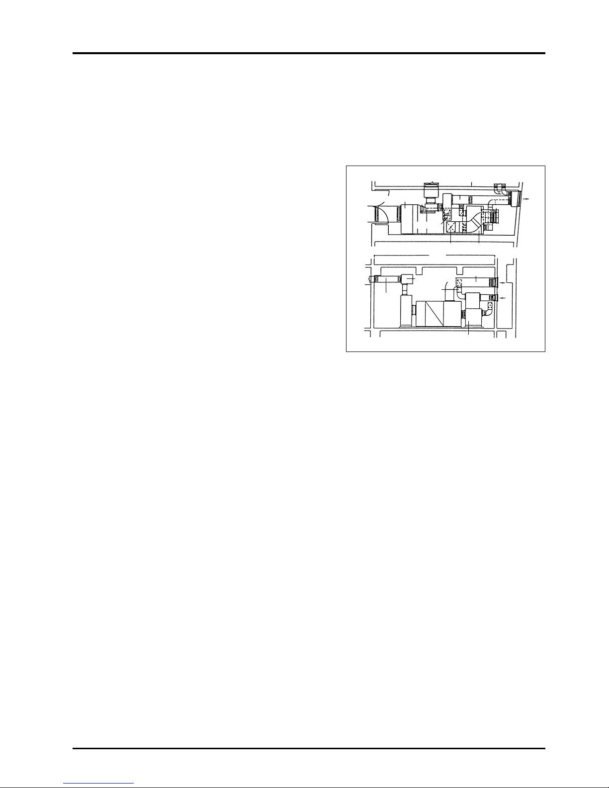
77
CHAPTER 6 ● Examples of Lossnay Applications
3.3 Plan details
(1) Lower floors for business
A machine room installation-type package and building
Lossnay is applied as a centralized method for each unit.
(One system for ground and 1st floor banking institution, one
system for 2nd and 3rd floor hall.)
(2) Mid- to upper floors for office tenants
As an air conditioning system for each floor unit, a package
air conditioner and Lossnay LP is combined in the machine
room to handle the interior load and ventilation, and a ceiling
suspended cassette-type package to handle the perimeter.
The toilet and kitchenette are ventilated with a straight
centrifugal fan on each floor, and supply for the outdoor air is
provided to the LP Lossnay air supply.
This allows independent operation and control for each floor.
(3) Control room, lounge, etc.
Independent use is possible with the ceiling suspended-type
air-conditioner and ceiling suspended cassette-type Lossnay.
• 4F to 8F:
Tenant offices – Lossnay installation sites:
machine room on each floor
To reduce installation space, a package-type LP Lossnay
with built-in air-supply fan and filter is incorporated and
combined with the air conditioner in the machine room on
each floor.
1.600 × 650 × 500H
6.800
500 × 500
600 × 500
600 × 500
Lossnay
900 × 400
300 × 250
1.600 × 650 × 500H
Lossnay
OA
shaft
500 × 400
Page 81
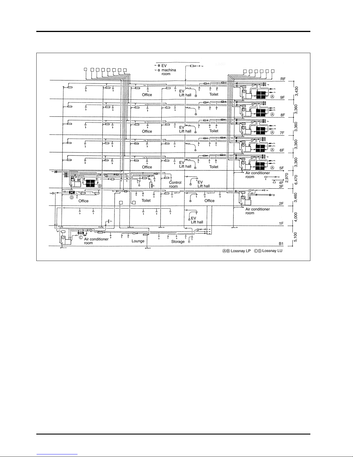
78
CHAPTER 6 ● Examples of Lossnay Applications
Air conditioning system diagram
3.4 Effect
(1) Management in tenant units is clear and simple
(2) Maintenance is simple as the maximum centralization can be planned while having independent tenants.
(3) As ventilation units are considered per floor, there are few openings on the outer wall, making designing of the outer wall
more simple.
(4) Outdoor air cooling is possible while ventilating.
Page 82
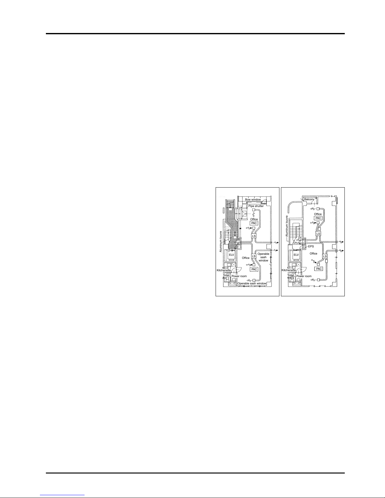
4.3 Plan details
(1) Air conditioning
●
Space efficiency and comfort during cooling/heating is improved with ceiling embedded cassette-type package air
conditioner.
(2) Ventilation
●
Room Entire area is ventilated by installing several ceiling embedded-type Lossnay units.
●
Salon corner Humidification is possible by adding a humidifier.
(Outdoor air is supplied to the toilet and kitchenette by setting the selection switch on the
Lossnay unit for supply to the extra-high notch.)
●
Conference room Area is independently ventilated by installing a ceiling embedded-type or cassette-type Lossnay
●
Board room in each room.
●
Toilet, powder room
Area is exhausted with straight centrifugal fan or duct ventilation fan.
●
Kitchenette
(An adequate exhaust volume can be obtained by taking in outdoor air, with the toilet being
ventilated constantly.)
●
Position of air intake/exhaust air outlets on outer wall
The freshness of the outdoor air taken in by the Lossnay is important, thus considering
that the building is surrounded by
other buildings, the intake and exhaust ports must be separated as far as possible.
79
CHAPTER 6 ● Examples of Lossnay Applications
4. Urban Small-Scale Building
4.1 System plan points
This system is based on effectively using available space within a limited area by installing the air conditioner and ventilator in
available excess space.
For this application, the air flow must be considered for the entire floor with the ventilator installed in the ceiling space.
Setting outline
●
Application : Office
●
Building form : RC (Reinforced Concrete)
●
Total floor space : 552 m2(B1 to 5F)
●
Application per floor : B1: Parking area
GF to 5F: Office
●
Air conditioning : Package air conditioner
●
Ventilation : Ceiling embedded-type and cassette-type Lossnay, straight centrifugal fan, duct ventilation fan.
4.2 Current topics
(1) Three sides of the building are surrounded by other buildings,
and windows cannot be installed. (Dependency on
mechanical ventilation is high.)
(2) Ample fresh outdoor air cannot be supplied. (Generally, only
Class 3 ventilation (forced exhaust) is possible.)
(3) If the exhaust in the room is large, odors from the toilet, etc.,
flow into the room.
(4) Humidification during winter is not possible.
}
}
}
GF layout 1F to 5F layout
PAC : Package air conditioner
LS : Lossnay
Page 83

80
CHAPTER 6 ● Examples of Lossnay Applications
4.4 Effect
(1) Accurate ventilation is possible with Class 1 ventilation (forced simultaneous air intake/exhaust) using the Lossnay.
(2) Outdoor air supply to the toilet and kitchenette is possible with the Lossnay, and accurate ventilation is possible even in
highly sealed buildings.
(3) Flow of odors can be prevented with constant ventilation using an adequate ventilation volume.
(4) Humidification is possible by adding a simple humidifying unit to the Lossnay.
5. Hospitals
5.1 System plan points
The principle of ventilation in hospitals requires adequate exhausting from the generation site and ensuring a supply of ample
fresh air. An appropriate system would be an independent ventilation system with Class 1 ventilation (forced simultaneous air
intake/exhaust).
The fan coil and package air conditioning are used according to material and place, and the air conditioned room is ventilated
with the ceiling embedded-type Lossnay. The toilet and kitchenette, etc., are ventilated with a straight centrifugal fan.
Setting outline
●
Building form : RC (Reinforced Concrete)
●
Total floor space : 931 m2(GF to 2F)
●
Application per floor : GF : Waiting room, diagnosis rooms, surgery theatre, director room, kitchen
1F : Patient rooms, nurse station, rehabilitation room, cafeteria
2F : Patient rooms, nurse station, head nurse room, office
●
Air conditioning : Fan coil unit, package air conditioner
●
Ventilation : Ceiling embedded-type Lossnay, straight centrifugal fan
5.2 Current topics
(1) Prevention of in-hospital transmission of diseases
(Measures meeting needs for operating rooms, diagnosis rooms, waiting rooms and patient rooms are required.)
(2) Adequate ventilation for places where odors are generated
(Measures to prevent odors from toilets from flowing to other rooms are required.)
(3) Shielding of external noise
(Shielding of noise from outside of building and noise from adjacent rooms and hallway is required.)
(4) Assurance of adequate humidity
(5) Energy conservation
Page 84
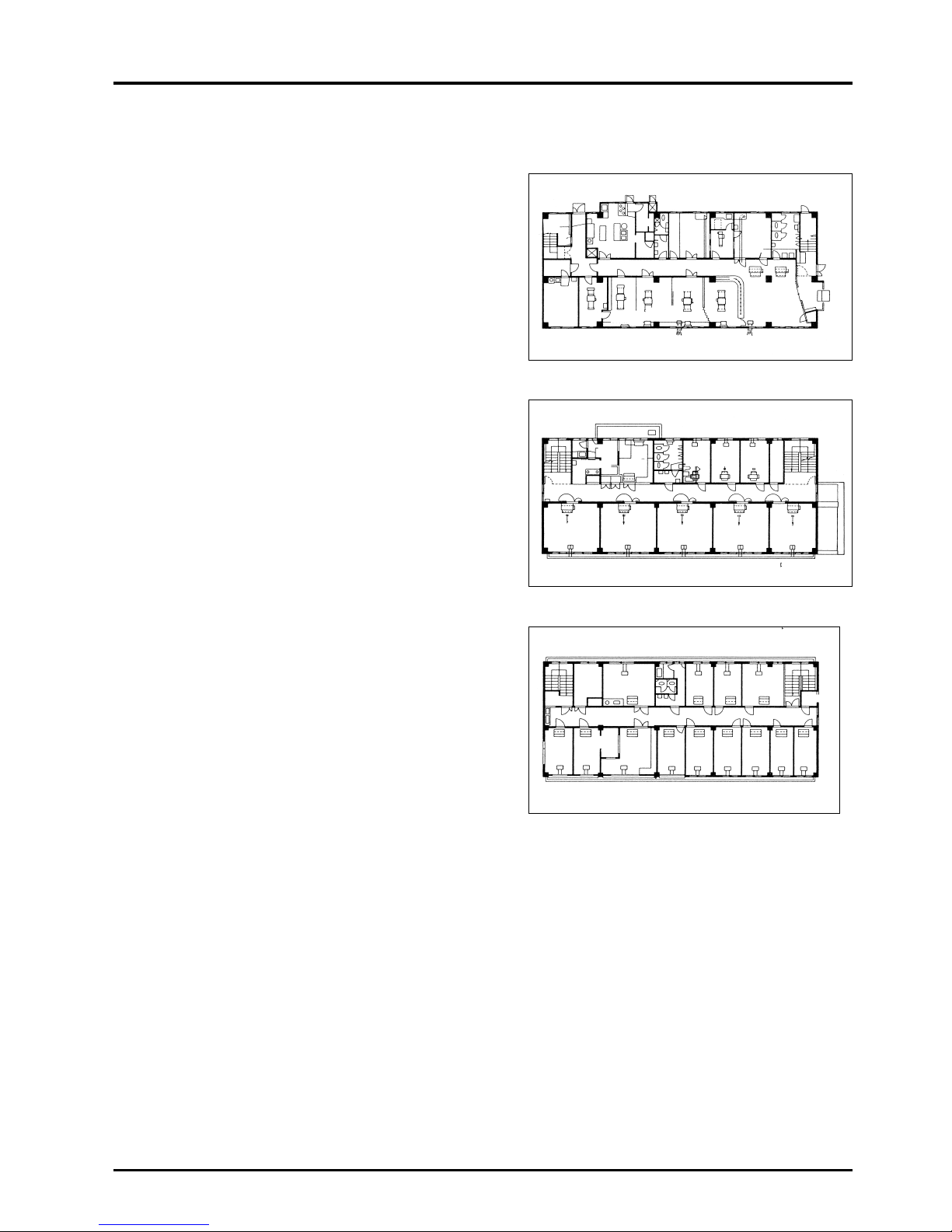
Reception
81
CHAPTER 6 ● Examples of Lossnay Applications
5.3 Plan proposals
(1) Air conditioning
● Centralised heat source control using a fan coil for the
general system allows efficient operating time control and
energy conservation.
● 24-hour system using a package air conditioner for special
rooms (surgery theatre, nurse station, special patient
rooms, waiting room) is the most practical.
(2) Ventilation
●
Hall system
Independent system using centralised control with LP
Lossnay or independent system with installation of ceiling
suspended-type Lossnay
●
Surgery theatre
Combination use of LP Lossnay and package airconditioner with HEPA filter on room supply air outlet.
●
Diagnosis rooms and examination room
Patient rooms
Nurse stations
Independent ventilation for each room using ceiling
suspended/ embedded-type Lossnay.
●
Integral system with optional humidifier possible for
required rooms.
●
Positive/negative pressure adjustment, etc., is possible
by setting main unit selection switch to extra-high notch
(25R, 50R models) according to the room.
●
Toilet/kitchenette
Straight centrifugal fan or duct ventilation fan
●
Storage/linen closet
Positive pressure ventilation fan or duct ventilation fan
The outdoor air is supplied from the hallway ceiling with the
straight centrifugal fan, and is distributed near the air
conditioner after the air flow is reduced.
●
Kitchen
Exhaust with negative pressure ventilation fan or straight
centrifugal fan. Outdoor air is supplied with the straight
centrifugal fan.
●
Machine room
Exhaust with positive pressure ventilation fan.
GF layout
1F layout
2F layout
Medicine
supply
storage
Gastro
camera
room
X-ray
room
Kitchen
Surgery
theatre
Machine
room
Director
room
Inspection
room
Diagnosis
room
Pharmacy
Storage
Waiting
room
Lossnay
Foyer
Prep
room
Nurse
beds
Nurse
station
Patient
room
(1 bed)
Patient
room
(1 bed)
Patient
room
(1 bed)
Patient
room
(4 beds)
Cafeteria/
lounge
Lossnay
Lossnay
Storage
Patient
room
(4 beds)
Patient
room
(4 beds)
Rehabilitation
room
Kitchenette
Storage/
machine
room
Conference
room
Patient
room
(1 bed)
Patient
room
(1 bed)
Patient
room
(1 bed)
Patient
room
(1 bed)
Patient
room
(1 bed)
Patient
room
(1 bed)
Patient
room
(1 bed)
Patient
room
(1 bed)
Storage
Patient
room
(2 beds)
Nurse
beds
Nurse
station
Head
nurse
room
Office
Treatment
room
Page 85

82
CHAPTER 6 ● Examples of Lossnay Applications
5.4 Effect
(1) The following is possible by independently ventilating the air-conditioned rooms with the Lossnay:
●
Transmission of diseases can be prevented by shielding the air between rooms.
●
Infiltration of outside noise can be prevented with the Lossnay Core’s soundproof properties.
●
As outdoor air does not need to be taken in from the hallway, the door can be sealed, shutting out hallway noise.
●
Humidification is possible by adding a humidifier.
(2) By exhausting the toilet, etc., and supplying outdoor air to the hallway:
●
Flowing of odors to other rooms can be prevented.
6. Schools
6.1 System plan points
A comfortable environment in classrooms is necessary to improve the children and students’ desire to study.
Schools near airports, railroads and highways have sealed structures to soundproof the building, and thus air conditioning and
ventilation facilities are required. This is also true for schools in polluted areas such as industrial districts.
At university facilities which have a centralised design to efficiently use land and to improve the building functions, the room
environment must also be maintained with air conditioning.
6.2 Current system details and problem points
(1) Mainly single duct methods, fan coil unit methods, or package methods are used for cooling/heating, but the diffusion rate
is still low, and water-based heaters are still the main source of heating.
(2) The single duct method is difficult to control according to the usage state, and there are problems in running costs.
(3) Rooms are often ventilated by opening the windows or using a ventilation gallery, where although this provides ample
ventilation volume it may create a problem of infiltration of outside noise.
6.3 Building outline
Total floor space : 23,000 m
3
Building outline : Prep school (high school wing)
Memorial hall wing
Library wing
Main management wing
Page 86
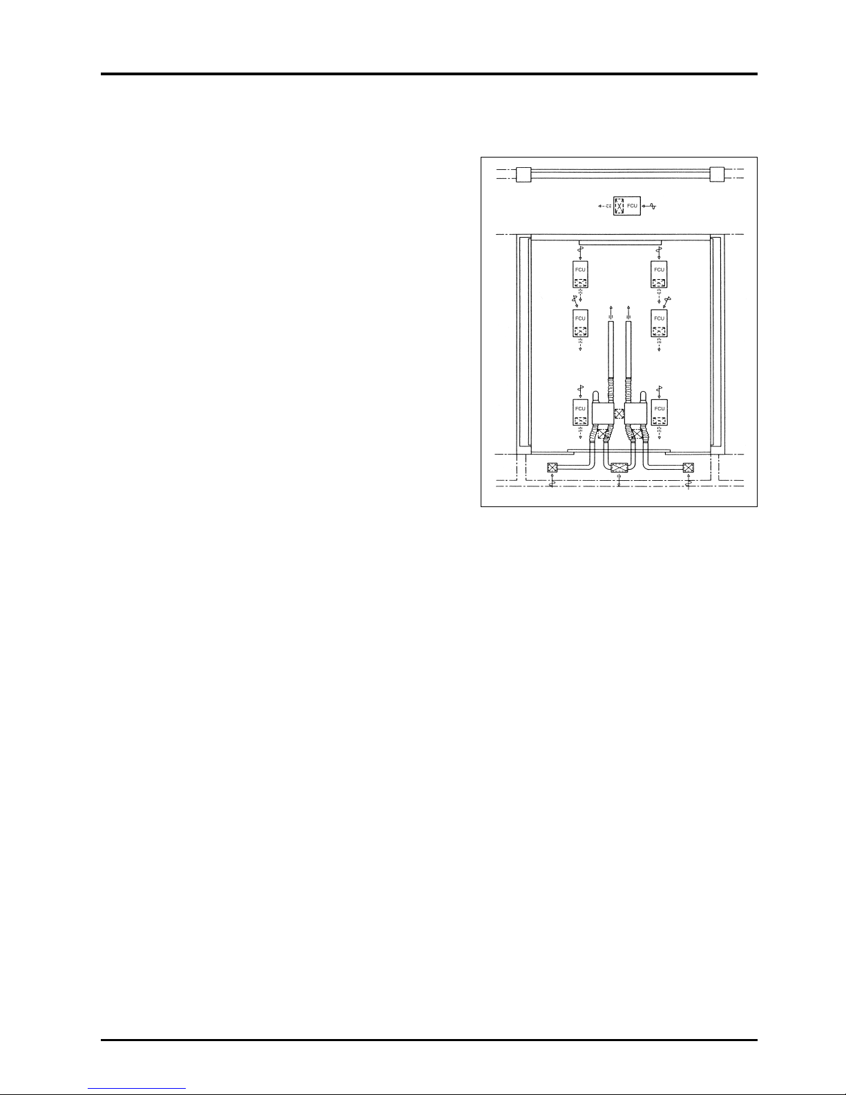
83
CHAPTER 6 ● Examples of Lossnay Applications
6.4 Plan details
(1) To pursue comfort, save energy and space, an air
conditioning and ventilation system using a ceiling
embedded-type fan coil unit and ceiling embedded-type
Lossnay was applied.
(2) Automatic operation using a weekly program timer was
applied, energising when the general classrooms and special
classrooms are to be used.
(3) By using a ventilation system with a total heat recovery unit,
energy is saved and soundproofing is realised.
6.5 Conditions for air-conditioning in
schools
(1) Zoning according to application must be possible.
(2) Response to load fluctuations must be swift.
(3) Ventilation properties must be good.
(4) The system must be safe and rigid.
(5) Expansion of the facility must be easy.
(6) Installation on existing buildings must be possible.
(7) Installation and maintenance cost must be low.
6.6 System trends
(1) It is believed that environmental needs at schools will continue to progress towards high quality, and various factors such
as temperature/humidity, noise, natural lighting, and colour must be considered at the design stages. Important topics are
air conditioning, ventilation and soundproofing.
(2) Independent heating using a centralised control method is mainly applied when the air conditioner is for heating only. For
cooling/heating, a combination of a fan coil method and package-type is the main method used.
(3) Highly accurate Class 1 ventilation is applied for the ventilation method, and the total heat recovery unit is mainly used in
consideration of the energy saved during air conditioning and the high soundproofing properties.
Classroom layout
(Hallway) SA RA
RA
RA
RA
RA
SA
SA
RA
SA
SASA
OA EA OA
(Veranda)
RA
LS LS
SA SA
SA
(Classroom)
Page 87

84
CHAPTER 6 ● Examples of Lossnay Applications
7. Hotels (convention halls, wedding halls)
7.1 System plan points
Hotels in Japan often have functions such as a resort hotel at tourist spots, convention hotel with conference and banquet
halls, and business hotels for short-term stays. These are all labeled as hotels, and often, more importance is laid on the
wedding, convention and banquet halls, etc.
This is because air conditioning systems in these places must have a ventilation treatment system that can handle extremely
large fluctuations in loads, tobacco smoke and removal of odors.
7.2 Current systems and problem points
CO and CO
2 permissible values, removal of odors, and tobacco smoke are often considered as standards for ventilation and
often the ventilation is set at 30 m
3
/h·person to 35 m3/h·person. Several outdoor air introduction-type package air conditioners
or air handling unit facilities are often used, but, these are greatly affected by differences in capacity, ratio of smokers and
length of stay.
7.3 Plan details
This proposed plan has two examples with the use of a Lossnay as a ventilator for total heat recovery in the air conditioned
conference room, and the use of several outdoor air type package air-conditioners for convention and banquet halls.
A) Conference room
Heat recovery ventilation is executed with constant use of the Lossnay unit, but when the number of persons increases
suddenly and the CO
2 concentration reaches a set level (for example, 1,000 ppm in the Building Management Law), a
separate centrifugal fan operates automatically. This system can also be operated manually to rapidly remove smoke and
odors.
B) Convention and banquet halls
Basically, this system is composed of several outdoor air introduction-type package air conditioners and straight
centrifugal fans for ventilation. However, an inverter controller is connected to the centrifugal fan so that it is constantly at
50 percent of the operation state, allowing fluctuations in ventilation loads to be handled. By interlocking with several
package air-conditioners, detailed handling of following up the air condition loads in addition to the ventilation volume is
possible.
Systems using Lossnay are also possible.
Conference room ventilation system diagram
Convention and banquet hall ventilation system diagram
LS : Lossnay
EX : Centritugal fan
PAC : Package air conditioner
EX : Centritugal fan
PAC : Package air conditioner
IB : Inverter controller
Page 88

85
CHAPTER 6 ● Examples of Lossnay Applications
7.4 System trends
The load characteristics at hotels is complex compared to general buildings, and are greatly affected by the bearing, time, and
operation state as mentioned above. Further to this, the high ceilings in meeting rooms and banquet halls, requires preheating
and precooling to be considered. Further research on management and control systems and product development will be
required in the future to pursue even further comfortable control within these spaces.
8.
Public Halls (combination facilities such as day-care centres)
8.1 System plan points
Air conditioning and ventilation facilities for buildings located near airports and military bases, etc., that require soundproofing,
have conventionally been of the centralised method. However, independent dispersed air conditioning and ventilation has
been demanded due to the need for operation in zones, as well as for energy conservation purposes. This system is a plan for
these types of buildings.
Setting outline
●
Building form : Above ground 2, Total floor space: 385 m
2
●
Application : GF Study rooms (2 rooms), office, day-care room, lounge
1F
. . . . .
Meeting room
●
Air conditioning : GF Air-cooling heat pump chiller and fan coil unit
1F
. . . . .
Air-cooling heat pump package air conditioner
●
Ventilation : Ceiling embedded Lossnay
8.2 Conventional system and topics
(1) Conventional systems have used centralised methods with air handling units, and air conditioning and ventilation were
generally performed together.
(2) Topics
1) Special knowledge is required for operation, and there are problems in response to the users’ needs.
2) When the centralised method is used, the air even in rooms that are not being used is conditioned, increasing
running costs unnecessarily.
3) Machine room space is necessary.
4) Duct space is necessary.
8.3 Plan details
(1) Air conditioning facilities
1) Small rooms : Air-cooling heat pump chiller and fan coil unit combination
2) Meeting rooms : Single duct method with air-cooling heat pump package air conditioner
(2) Ventilation facilities
1) A ceiling embedded-type Lossnay is used in each room, and a silence chamber, silence-type supply/return grille,
silence duct, etc. is incorporated on the outer wall to increase the total soundproofing effect.
Page 89
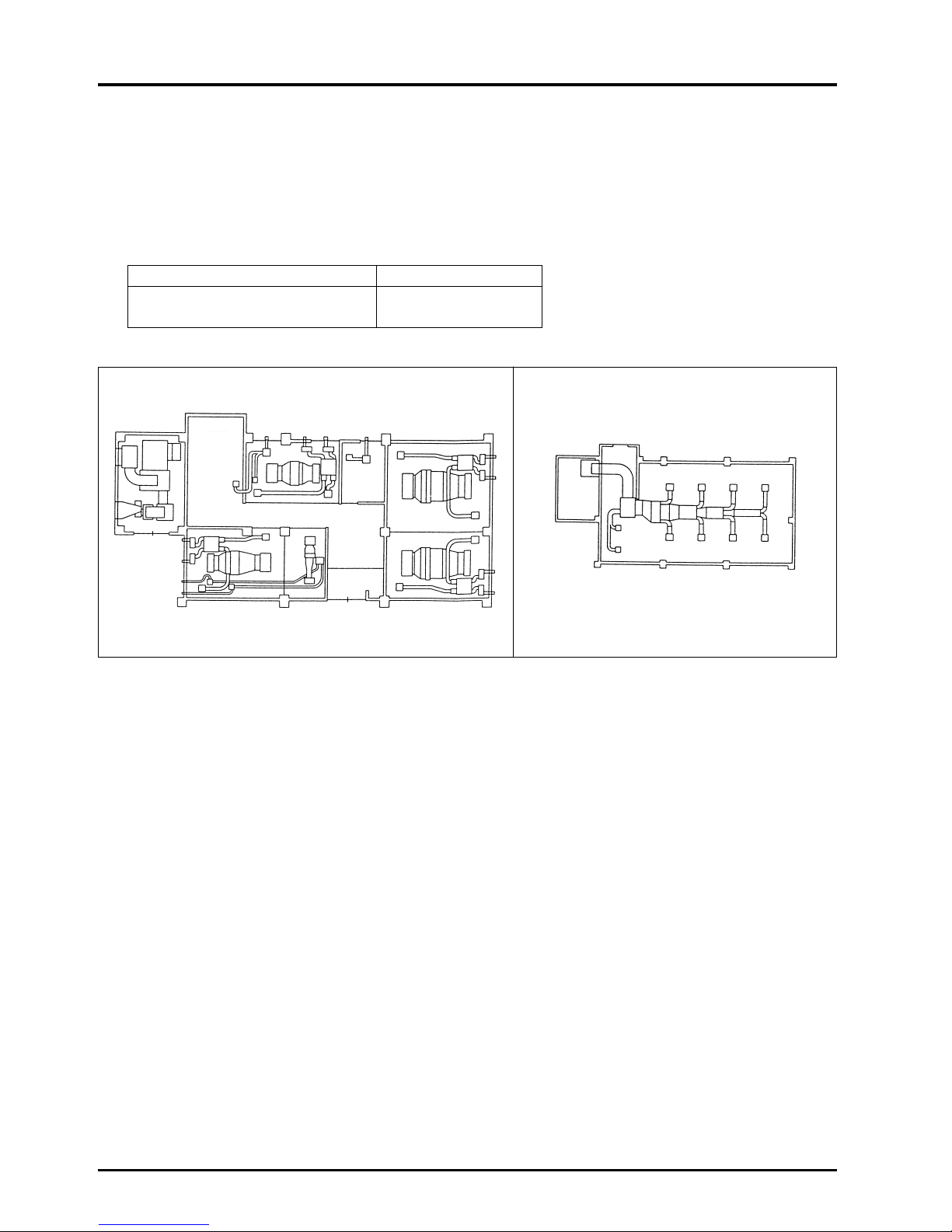
Soundproofing standards Soundproofing effect
High pressure level difference Study room : 34.0 dB
30 dB or more Rest room : 47.2 dB
86
CHAPTER 6 ● Examples of Lossnay Applications
8.4 Effect
(1) Operation is possible without special knowledge, so management is easy.
(2) Operation is possible according to each room’s needs, and is thus energy-saving.
(3) Soundproof ventilation is possible with the separately installed ventilators.
(4) Energy saving ventilation is possible with the heat recovery ventilation.
(5) Space saving with the ceiling embedded-type.
➞
GF layout 1F layout
Machine room
Kitchenette
Stairway
Toilet
Hall
Foyer
Study room
Day-care room
FCU
FCU
FCU
Lounge
Study room
Meeting room
LS
PAC
PAC
LS
LS
LS
Page 90

CHAPTER 7
Installation Considerations
Page 91
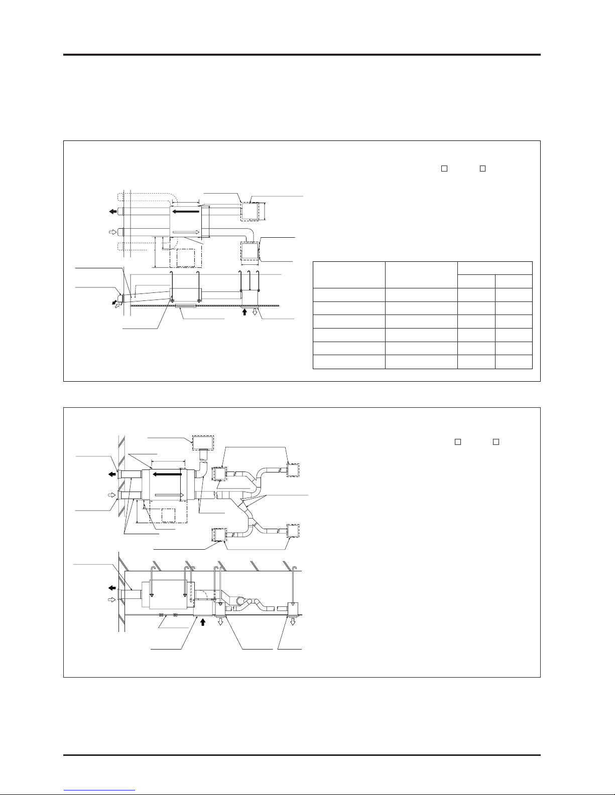
●
Always leave inspection holes ( 450 or 600) on the
air filter and Lossnay Core removal side.
●
Always insulate the two ducts outside the room (intake
air and exhaust air ducts) to prevent frosting.
●
It is possible to change the direction of the outside air
ducts (OA and EA side).
●
It is possible to attach a suspension bolt.
●
Do not install the vent cap or round hood where it will
come into direct contact with rain water.
88
CHAPTER 7 ● Installation Considerations
1. LGH-Series Lossnay Ceiling Embedded-Type
(LGH-RX
3 Series)
LGH-15 · 25 · 35 · 50 · 80 · 100RX3 models
●
Always leave inspection holes ( 450 or 600) on
the air filter and Lossnay Core removal side.
●
Always insulate the two ducts outside the room
(intake air and exhaust air ducts) to prevent frosting.
●
If necessary, order a weather cover to prevent rain
water from direct contact or entering the unit.
LGH-150 · 200RX
3
■ Installation diagram
■ Installation diagram
Exhaust air grill
(ordered by customer)
Supply air grill
(ordered by customer)
Suspension bolt position
1030
Exhaust air grill
(ordered by customer)
600 or more
150 to 250
LGH-150RX
3
(LGH-200RX3)
LGH-150RX
3
(LGH-200RX3)
Inspection
opening
1046
(1273)
414
Duct ø 350
(ordered by customer)
Duct ø 350
(ordered by customer)
414
Suspension bolt position
Supply air grill
PZ-20FG
3 or PZ-25FG3
Y pipe, one direction
falling pipe
(ordered by
customer)
Supply air grill
PZ-20FG
3 or PZ-25FG3
Suspension bolt position
Maintenancespace
forelementairfilterand
air-supplyfan
Suspension bolt
(ordered by customer)
Inspection
opening
Duct downward slope
1/30 or more (to wall side)
(Rainwater entrance
prevention)
OA (Outside air)
EA (Exhaust air)
OA (Outside air)
EA (Exhaust air)
RA (Return air)
Exhaust air grill
SA (Supply air)
Supply air grill
SA
(Supply air)
Supply
air grill
A
OA
(Outside air)
EA
(Exhaust air)
OA (Outside air)
EA (Exhaust air)
414
414
Suspension bolt position
Suspension bolt position
Suspension bolt
position
Exhaust air grill
PZ-20FG
3
B
Supply air grill
PZ-20FG
3
600 or more
150 to 250
Inspection
opening
Duct downward slope 1/30
or more (to wall side)
Deep-type hood or
weather cover
Duct diameter ø200
(ordered by customer)
Inspection opening
Supply/
exhaust air grill
Suspension bolt position
(ordered by customer)
RA
(Return air)
SA
(Supply air)
Lossnay Core/
air filter/
fan maintenance
space
(Rainwater entrance
prevention)
Air volume (m3/h) Model
Dimension
AB
150 LGH-15RX
3 700 641
250 LGH-25RX
3 700 765
350 LGH-35RX
3 790 906
500 LGH-50RX
3 790 1,048
800 LGH-80RX
3 1,030 1,036
1000 LGH-100RX
3 1,030 1,263
Unit (mm)
Unit (mm)
Page 92

89
CHAPTER 7 ● Installation Considerations
(1) The ceiling embedded-type: 150 · 250 · 350 · 500 · 800 · 1000 · 1500 and 2000 m3/h types are available.
Select an adequate model according to the room size, air volume for the application and noise levels.
(2) The LGH-15 · 25 · 35 · 50 · 80 · 100 types have an extra-high notch. This setting is for when a long duct is used or when
a large air volume is required. The positive and negative pressures of the room can also be adjusted with this.
LGH-15 · 25 · 35 · 50 · 80 · 100RX
3
LGH-150 · 200RX3
(3) The units have a low-noise design, however, for further noise reduction a silencer-type supply/return grille (PZ-FG-type)
for supply/return air in the room, a silencer box (PZ-SB-type) for reducing the air sound into the room, and a flexible
silencer (PZ-SD-type) are available.
Silencing effect of each part
Model Silencing effect Application models Duct diameter
PZ-10FG
3 3 dB LGH-15RX3 ø100
Supply/return grille
PZ-15FG
3 4 dB LGH-25RX3 ø150
PZ-20FG
3 4 dB LGH-35 · 50RX3 ø200
PZ-25FG
3 4 dB LGH-80 · 100RX3 ø250
Silencer box
PZ-20SB
2 6 dB LGH-35 · 50RX3 ø200
PZ-25SB
2 6 dB LGH-80 · 100RX3 ø250
PZ-10SD 22 dB LGH-15RX
3 ø100
Flexible silencer
PZ-15SD 21 dB LGH-25RX
3 ø150
PZ-20SD 20 dB LGH-35 · 50RX
3 ø200
PZ-25SD 18 dB LGH-80 · 100RX
3 ø250
Exhaust air
High and Extra High switch
High and Extra High switch
Supply air
High
High
E-High
E-High
Exhaust air
Supply air
High
High
E-High
E-High
Page 93

90
CHAPTER 7 ● Installation Considerations
1.1 Selecting Duct Attachment Direction
You can choose between two directions for the outside duct (OA, EA) piping direction, to improve construction.
Standard Construction Construction with the Direction Changed
OA
EA
OA
EA
OA
EA
*A space is
necessary to
prevent rain
water from
entering.
■ It is possible
to set the unit
close to a
wall.
■ You can avoid
obstructions of the
supply and exhaust
ducts by lights or air
conditioners.
Light, etc.
1.2 Installation and maintenance
(1) Always leave an inspection hole ( 450) on the filter and Lossnay Core removal side.
(2) Always insulate the two ducts outside the room (intake air and exhaust air ducts) to prevent frosting.
(3) Enforce measures to prevent rain water from entering.
●
Apply a slope of 1/30 or more towards the wall to the two ducts outside the room (intake air and exhaust air ducts).
●
Do not install the vent cap or round hood where it will come into direct contact with rain water.
(4) Use the optional parts “control switch” (Ex. PZ-41SLB, etc.) for the RX
3-type.
A centralised controller can also be used.
1.3 Installation applications
(1) Combined installation of two units
The main unit’s supply outlet and suction inlet and the
room side and outdoor side positions cannot be
changed. However, the unit can be turned over, and
installed as shown below. (This is applicable when
installing two units in one classroom, etc.)
(2) System operation with air conditioner
Air conditioning systems with independent dispersed
multiple unit air-conditioners are increasing due to
merits such as improved controllability, energy
conservation and space saving.
For these types of air conditioning systems, combined
operation of the dispersed air conditioners with the
Lossnay, is possible.
EA
SA SA
RA RA
OA EA
Reversed
installation
Lossnay Lossnay
Inspection
opening
Standard
installation
Cassette-type packaged air
conditioner or fan coil unit
Return grill
Exhaust
Air intake
Air intake
Ceiling embeddedtype Lossnay
Ceiling embedded-type package
air conditioner or fan coil unit
Return grill
Ceiling
Ceiling
Exhaust
Ceiling embeddedtype Lossnay
Page 94

91
CHAPTER 7 ● Installation Considerations
2. Business Lossnay Suspended Exposed-Type
(1) Leave at least a 400 mm maintenance space at the right side of the main unit for connection of the control switch and
power to the main unit.
When attaching square duct When attaching round duct
25
250 250
600
50
30
23
201
170
540
1175
400 or more
80
to
300
590 (630)357 (337)
42
(63)
83
210
(250)
310
193
1245
86
120
123
300
ø192
ø208
400 or
more
540
1175
400 or more
600 or more
Slot for power line Supply air box attachment hole
( ) is the hole measurement when using
wood boards with a thickness of 20 mm.
Use PZ-50ECV2 in combination
with PZ-50EDB
2 or PZ-50EKD2.
This unit can not be used in
separate combination with the
main unit.
Bolt and nut for suspension (ordered by user)
Wall
Attachment
screw
(included)
Weather cover
(part sold separately, parts
code PZ-50ECV
2)
Weather cover
(PZ-50ECV2)
SA (Supply air)
RA (Return air)
Bellows
Air supply box with bellows
(sold separately, parts code
PZ-50EKB
2, 50EKD2)
Air supply box with bellows
(sold separately, parts code PZ-50EKB
2, 50EKD2)
Lossnay main unit
OA (Outside air)
EA (Exhaust air)
(2) When the installation position is decided, make a hole in the wall for the supply air box with bellows. See the following unit
regarding the size and position in relation to the Lossnay main unit.
(3) If using wood boards for installation, make wood boards that match the hole size dimensions for wood boards shown in
the illustration above. In this case, make the size of the hole in the wall such that wooden boards of the dimensions given
above can fit through.
(4) Use the extension bellows (PZ-50EJ
2) or the extension duct if the space between the flange of the main unit and the
bellows connection area of the supply air box with bellows is more than 200 mm.
CAUTION
When connecting round ducts, remove the square flange, and attach the round ducts as shown below.
Square flange
Lossnay main unit
Round duct flange
(included with main unit)
Lossnay main unit
Screw
Suspension bolt position
Back side OA, EA hole position
When attaching
square flange
When attaching round
duct connection flange
Center of Lossnay
main unit
Suspension bolt nut
(ordered by customer)
PZ-50ECV
2
weather cover
(sold separately)
Suspension bolt nut
(ordered by customer)
PZ-20CVU
weather cover
(sold separately)
PZ-50EKB2
Supply air box
with bellows
(sold separately)
Flexible duct ø 200
(commercial product)
Maintenance space for connection
Suspension bolt position
Back side OA, EA hole position
Maintenance space for connection
OA (Outside air)
SA (Supply air)
EA (Exhaust air)
RA
(Return air)
RA
(Return air)
OA
(Outside air)
SA
(Supply air)
EA
(Exhaust air)
Outside air intake
Exhaust air output
Outside air intake
Exhaust air output
Unit (mm)
Unit (mm)
Unit (mm)
Page 95

92
CHAPTER 7 ● Installation Considerations
3.
Building Lossnay Pack-type (LP-200B · 350B · 500B · 750B · 1000B)
System concept diagram Installation examples
LP-200B
LP-1000B
RA
OA
EA
SA
RA
OA
EA
SA
<Combination with air handling unit> <Combination with package air
conditioner>
(1) The LP-200B · 350B · 500B · 750B and 1000B building Lossnay Packs models are available with an air volume of 1000 to
13000 m
3
/h.
(2) Select an adequate model according to the building size, air volume for application and static pressure of outside unit.
Air passage
3.1 Main unit base installation
surface diagram
3.2 Maintenance space
1.The fresh outdoor air is filtered with the intake filter,
and the heat is recovered with the Lossnay Core
(during winter; heated and humidified, during summer;
cooled and dehumidified). Then it is supplied by the
supply fan.
2.The optional high efficiency filter is placed between the
Lossnay Core and supply fan, to refilter the air that has
been filtered by the intake filter.
3.The stale air passes through the damper, and is filtered
by the exhaust filter. The heat is recovered with the
Lossnay Core, and then discharged by the exhaust fan.
4.The bypass passage for normal ventilation bypasses
the air on the exhaust side. If the bypass damper is
closed, the stale air will be directly drawn in by the
exhaust fan and discharged.
50 50
50
AA
B
C
D
Package air conditioner
Air handling unit
Lossnay
LP-350B
Chamber
Lossnay
LP-350B
Chamber
Air handling unit
Package air
conditioner
Exhaust side tilter
By-pass damper
High efficiency
filter unit
(optional)
Supply fan
SA
(Supply air)
RA
(Return air)
Lossnay core
Supply air filter
Exhaust fan
OA
(Outdoor
air)
EA
(Exhaust
air)
6 - ø20 holes
Switch box
600
Maintenance
space for
air-supply
fan
800
Maintenance
space for
core
air filter
and airsupply
fan
Model A B C D
LP-200B 500 1230 950 1000
LP-350B 700 1560 1120 1170
LP-500B 950 2070 1230 1280
LP-750B 950 2070 1230 1280
LP-1000B 950 2070 1350 1400
Unit (mm)
Page 96
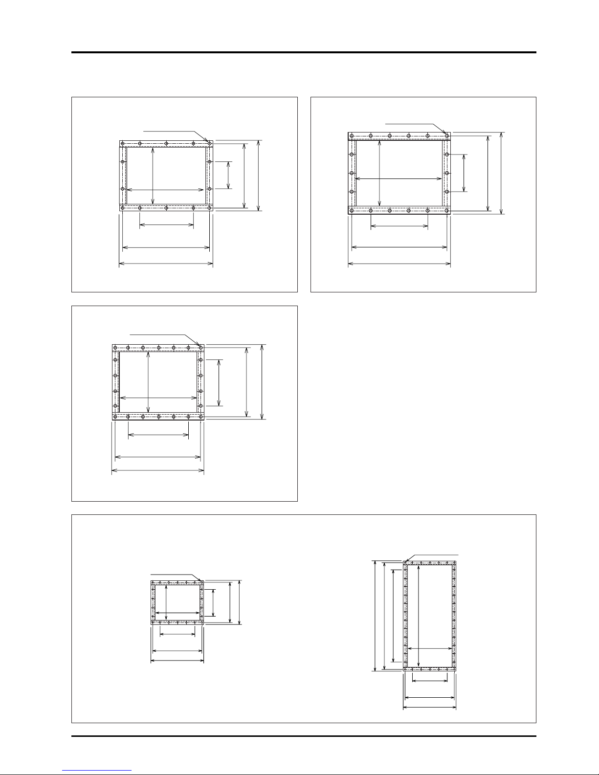
93
CHAPTER 7 ● Installation Considerations
3.3 Flange dimensions
430
390
100 × 2 = 200
350
100
250
290
330
480
440
100 × 3 = 300
400
100 × 2 = 200
325
365
405
LP-200B
Unit (mm)
580
540
100 × 4 = 400
500
100 × 3 = 300
405
445
485
LP-500B
Unit (mm)
LP-750B · 1000B
■ Supply flange details ■ Return flange details
Unit (mm)
Unit (mm)
LP-350B
620
580
100 × 4 = 400
540
100 × 11 = 1100
1200
1280
1240
620
580
100 × 4 = 400
540
100 × 3 = 300
405
445
485
14-ø 10 holes
Pitch
18-ø 10 holes
Pitch
22-ø 10 holes
Pitch
Pitch
Pitch
22-ø 10 holes
Pitch
Pitch
38-ø 10 holes
Pitch
Pitch
Page 97

94
CHAPTER 7 ● Installation Considerations
3.4 Transportation and installation
(1) LP-200B · 350B · 500B
●
The product is shipped in the fully assembled state.
Transport the unit gently and do not apply shock or tilt the
unit.
●
Use eyebolts (or eyenuts) when lifting the unit. Always use
the four eyebolts, and fix with rope. Adjust the rope length
so that the angle between the rope and the unit is 45° or
more.
The panel will be damaged if the rope directly contacts the
unit. Always use filler plates or wood.
●
The foundation for the unit must be sturdy and level.
●
Install the unit perpendicularly to the foundation and
securely fix the unit with anchor bolts.
●
Install the unit where it will not come into contact with rain
water, and where rain water will not enter the unit from the
ducts.
●
The unit may be disassembled into two parts, and
transported with the following procedure if installation as a
complete product is not possible.
Disassembly
1) Remove the cover for the air filter and Lossnay Core.
Remove the air filter and then the Lossnay Core.
2) Disconnect the cord (for bypass) connected to the fan
chamber motor in the lower part of the unit.
3) Remove the six screws fixing the top and bottom of the unit.
(2) LP-750B · 1000B
●
This product is shipped in two parts and assembled at the
installation site.
●
Always lift the Core chamber and the fan chamber
separately even when lifting the entire product in the
assembled state using the eyebolts (or eyenuts) mounted
on the unit.
●
Always be sure to use the eyebolts (or eyenuts) when lifting
the unit. Always use the four eyebolts, and securely fix the
rope. Adjust the rope length so that the angle between the
rope and the unit is 45° or more.
●
The foundation for the unit must be sturdy and level.
●
Install the unit perpendicularly to the foundation and
securely fix the unit with anchor bolts.
●
Install the unit so rain water will not enter the unit from the
ducts.
●
To assemble the separate parts, align the slots on the core
chamber to the bolts on top of the fan chamber, and fix with
the enclosed washers and nuts (six each).
●
Remove the inspection hole cover and connect the geared
motor plug for the bypass to the plug in the Core chamber
from inside.
Weight when disassembled Unit (kg)
Top Bottom
(Core (fan Total
chamber) chamber)
LP-200B 140 240 380
LP-350B 230 290 520
LP-500B 300 380 680
Weight when disassembled Unit (kg)
Top Bottom
(Core (fan Total
chamber) chamber)
LP-750B 140 240 380
LP-1000B 230 290 520
Filler plate
Screw
Washer
Cord (for by-pass)
Hook for
suspension
Page 98
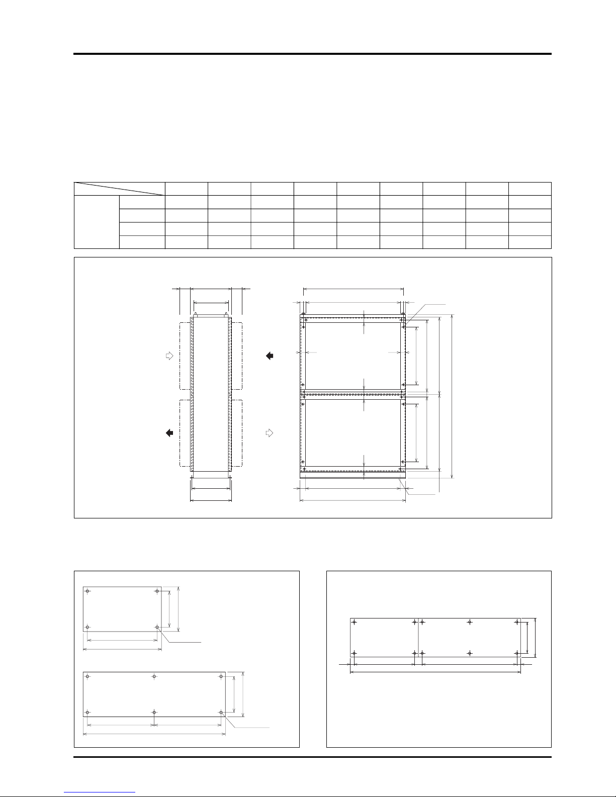
95
CHAPTER 7 ● Installation Considerations
4.
Building Lossnay Unit Vertical-type (LUT-2302 · 2303 · 3002 · 3003)
4.1 Main unit dimensions and flange dimensions
●
This unit is for indoor installation.
●
The flange is an inner-flange.
●
The special filter is not sold separately and must be prepared by the user.
(Two on Core’s intake side.)
Unit (mm)
4.2 Main unit installation surface diagram
■ Single-type floor installation surface diagram ■ Combination-type floor installation surface diagrams
(Example)
ABCDEFGHJ
LUT-2302 1000 900 950 900 2382 1125 1085 1000 4
Single- LUT-2303 1500 1400 1450 1400 2382 1125 1085 1000 6
type LUT-3002 1000 900 950 900 3132 1500 1460 1440 4
LUT-3003 1500 1400 1450 1400 3132 1500 1460 1400 6
500 or more 500 or more
575
495
C
40
4545
40 40
G
F
E
G
F
102
40
A
B
5050
525
575
50
50
Unit (mm)
900
1000
525
575
700 700
1500
525
575
50
900 1400
2500
50
525
575
100
LUT-2302, 3002 models For LUT-2305
(The single-type model installation surface is combined
in this case.)
LUT-2303, 3003 models
Unit (mm)
Unit (mm)
Maintenance space Maintenance space
D (hole Pitch 100)
ø13 hole
J-ø20 hole
(for fixing to floor)
H (hole pitch 100)
H (hole pitch 100)
4-ø20 hole
6-ø20 hole
LUT-2302 LUT-2303
Page 99
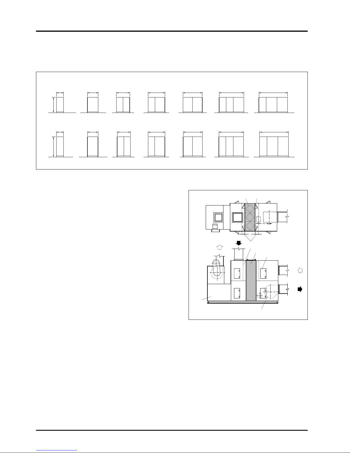
96
CHAPTER 7 ● Installation Considerations
4.3 Combination dimensions
●
The combined-type uses a combination of single-type units.
●
The combined-type is shipped in the disassembled state. (A combination of single-type units.)
LUT-2304
2000
LUT-2305
2500
LUT-2306
3000
LUT-2307
3500
LUT-2308
4000
LUT-3004
2000
3132
LUT-2303
1500
LUT-3003
1500
LUT-3002
1000
2382
LUT-2302
1000
LUT-3005
2500
LUT-3006
3000
LUT-3007
3500
LUT-3008
4000
SA
RA
OA
EA
Unit (mm)
4.4 Maintenance space
●
The Lossnay Core is cleaned from the intake/exhaust chamber
sides.
Allow an inspection space of 50 cm or more in the chamber.
●
Ensure that the Core inspection door can open and close, and
always install an inspection door for cleaning the ducts.
4.5 Transportation and installation
●
Always use shackles to lift the Lossnay Core section as shown in the figure. Fix the main unit with the eyenuts for lifting the
unit, and suspend the unit in four places. (Fig. 1)
●
Adjust the rope length so that the angle between the rope and the unit is 45° or more. (Fig. 1)
●
The panel will be damaged if the rope directly contacts the unit.
●
When combining the units, use the enclosed top connection fittings (two) and bottom connection fittings (two). Securely fix
the top with the four M10 screws and four washers and the bottom with eight M8 screws so that the fitting with the flange is
tight.
●
Always leave the maintenance space shown in the diagram.
●
The foundation for the unit must be sturdy and level.
●
Install the unit perpendicularly to the foundation and securely fix the unit with anchor bolts.
●
Install the unit so rain water will not enter the unit from the ducts.
Unit (mm)
Lossnay core Door
Maintenance space 500 or more
Filter
Lossnay
Inspection door
Exhaust fan
Air
conditioner
Page 100
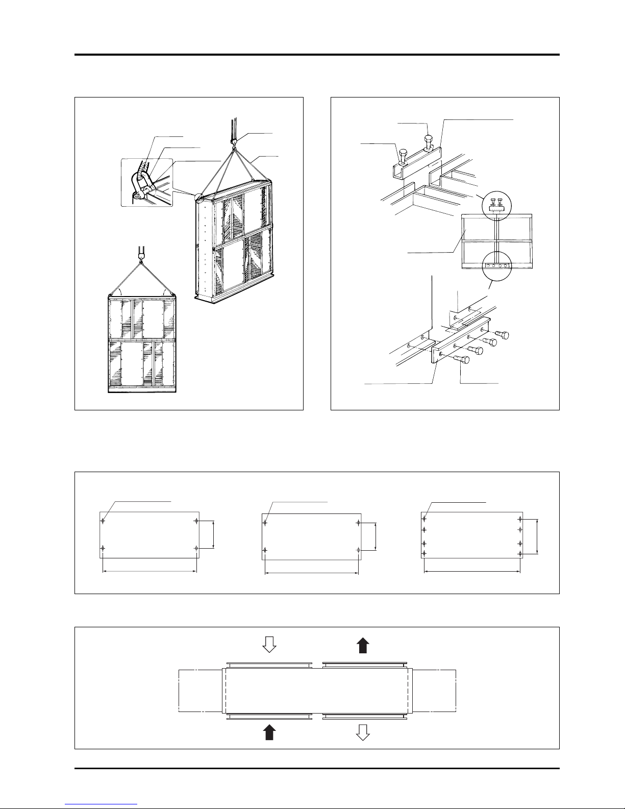
97
CHAPTER 7 ● Installation Considerations
45° or
more
45° or
more
Fig. 1 Fig. 2
5. Building Lossnay Unit Horizontal-type (LU-80 · 160 · 500)
5.1
Main unit installation surface diagram (anchor bolt installation position)
5.2 Maintenance space
Unit (mm)
Unit (mm)
300
1050
300
2050
200 × 3 = 600
2050
For LU-80 For LU-160 For LU-500
Rope
Shackle
Eyebolt for lifting
Crane
Rope
Top connection fitting
M10 screw
M8 screw
Washer
Lossnay unit
Bottom connection fitting
4-12 × 18 slots 4-12 × 18 slots 8-12 × 18 slots
Pitch
Min. 800 is
required for air
filter core
removal space.
Removal from
opposite side is
also possible.
 Loading...