

Page 1
Lossnay Energy Recovery Ventilator
Model:
0902874HN5301
LGH-50RSDC-E (220-240V 50Hz
Installation Instructions
)
(For use by dealer/contractor)
Contents
Safety precautions.............................................1
Outline drawings................................................2
Standard installation examples..........................3
Installation method.............................................4
Function settings................................................7
Trial operation....................................................8
This product needs to be installed properly in order to ensure maximum functionality as well as safety.
Please make sure to read this installation manual before starting the installation.
lInstallation must be performed by a dealer or installation contractor. Please note that improper installation may cause malfunction or accident.
Separate booklet “Operating Instructions” is provided for the customer.
The booklet and this manual must be handed over to the customer after completing the installation.
Safety precautions
The following signs indicate that death or serious injury may be caused by failure to heed the precautions described below.
Do not modify or disassemble.
(It could cause fire, electric shock or injury.)
Do not
disassemble
The Lossnay unit should not be installed where it is highly
humid, like a bathroom, or other wet place.
Prohibition of use in
bath or shower room
Connect the
grounding wire
The instructions
given must be
followed.
(It could cause electric shock or power leakage.)
Connect the product properly to ground.
(Malfunctioning or power leaks can cause electrical shock.)
.
Use the specified power supply and voltage.
(Use of incorrect power supply or voltage could cause fire or electric
shock.)
Select a place with sufficient strength and install the main unit
securely.
(It could cause injury if it falls.)
WARNING
The instructions
given must be
followed.
Wiring work must be performed by qualified professionals,
and be implemented safely and securely in accordance with
the engineering standards and the extension wiring rules for
electrical equipment.
(Poor connection or improper wiring work could cause electric
shock or fire.)
Install a power supply isolator at the power supply side as per
local electrical regulations.
(It could cause fire if power leakage occurs.)
All supply circuits must be disconnected before obtaining
access to the terminal devices.
Use the specified cable size and connect the cables securely to
prevent disconnection when they are pulled.
(If there is a defect in the connection, there is a possibility of fire.)
Select an adequate place for the opening to introduce outdoor air,
where it will not inhale the exhaust fumes like combustion gas, or
others, and there is no risk of blockage by snowfall or others.
(Shortage of fresh air could put the room in a state of oxygen deficiency.)
A duct made of steel must be installed with care not to be
connected electrically with metals such as metal, wire, stainless
steel plate, or others.
(It could cause fire when power leakage occurs.)
Prohibited
CAUTION
Do not place a burning appliance in a place where it is exposed
directly to the air from the Lossnay unit.
(It could cause an accident as a result of incomplete combustion.)
Do not place an object on or sit on the Lossnay unit.
(It could cause electric shock, fire, or other damage.)
Do not use at a place where exposed to high temperatures (40°C or
higher), naked flames, or in environment with combustible fumes.
(It could cause fire.)
Do not use in an environment such as a chemical factory, where
hazardous gases such as acidic gases, alkaline gases, organic
solvent fumes, paint fumes, or gases containing corrosive
components are generated.
(It could malfunction.)
Insulation failure caused by salt or sulphur air and hot spring
steam, Rust, fire or malfunction may occur.
Installing high quality filters inside outdoor air duct if the
Lossnay operates in salt or sulphur air conditions.
Do not install this product in a place where it is exposed to
ultraviolet light.
(UV may damage covering insulation.)
The instructions
given must be
followed.
Put on gloves during maintenance.
(It could cause injury.)
Make sure the power supply isolator is turned off on the power
distribution panel when Lossnay is not used for a long period
of time after the installation.
(It could cause electric shock, power leakage, or fire as a result of
deteriorated insulation.)
Always use the specified suspension bolts, nuts and washers.
(Use of hardware with insufficient strength could result in the product
dropping.)
The outside ducts must be tilted at a gradient (1/30 or more) down
toward the outdoor louvres from Lossnay, and properly insulated.
(The entry of rain water may cause power leakage, fire, or damage
to household property.)
The control box cover must be closed after the installation.
(Dust or humidity may cause power leakage or fire.)
When connecting external devices (electrically operated damper,
lamp, monitoring unit, etc.) using output signals of the Lossnay unit,
make sure to install safety equipment for the external devices.
(It could cause fire, damage, etc. without safety equipment.)
Page 2
10
73
1099
810
21
979 2020
21
7
1051
680
264
1119
283.5
302
20
89879 79
192
208
Safety precautions (continued)
lWhen using the product where it is exposed to high
temperatures and humidity (40°C or higher, RH 80% or higher),
or where fog occurs frequently, moisture is likely to condense
in the core, and may result in condensation build up in the unit.
The product should not be used under such conditions.
lOutdoor air may enter the Lossnay owing to the pressure
difference between indoor and outdoor or external winds even
when the product is not operated. It is recommended to install
also an Electrically operated damper to block the outdoor air.
lIn a cold weather area, an area with strong external winds or
where fog occurs frequently, cold outdoor air, external winds
or fog may be introduced into the product when its operation is
stopped. It is recommended to install an Electrically operated
damper to shut them out.
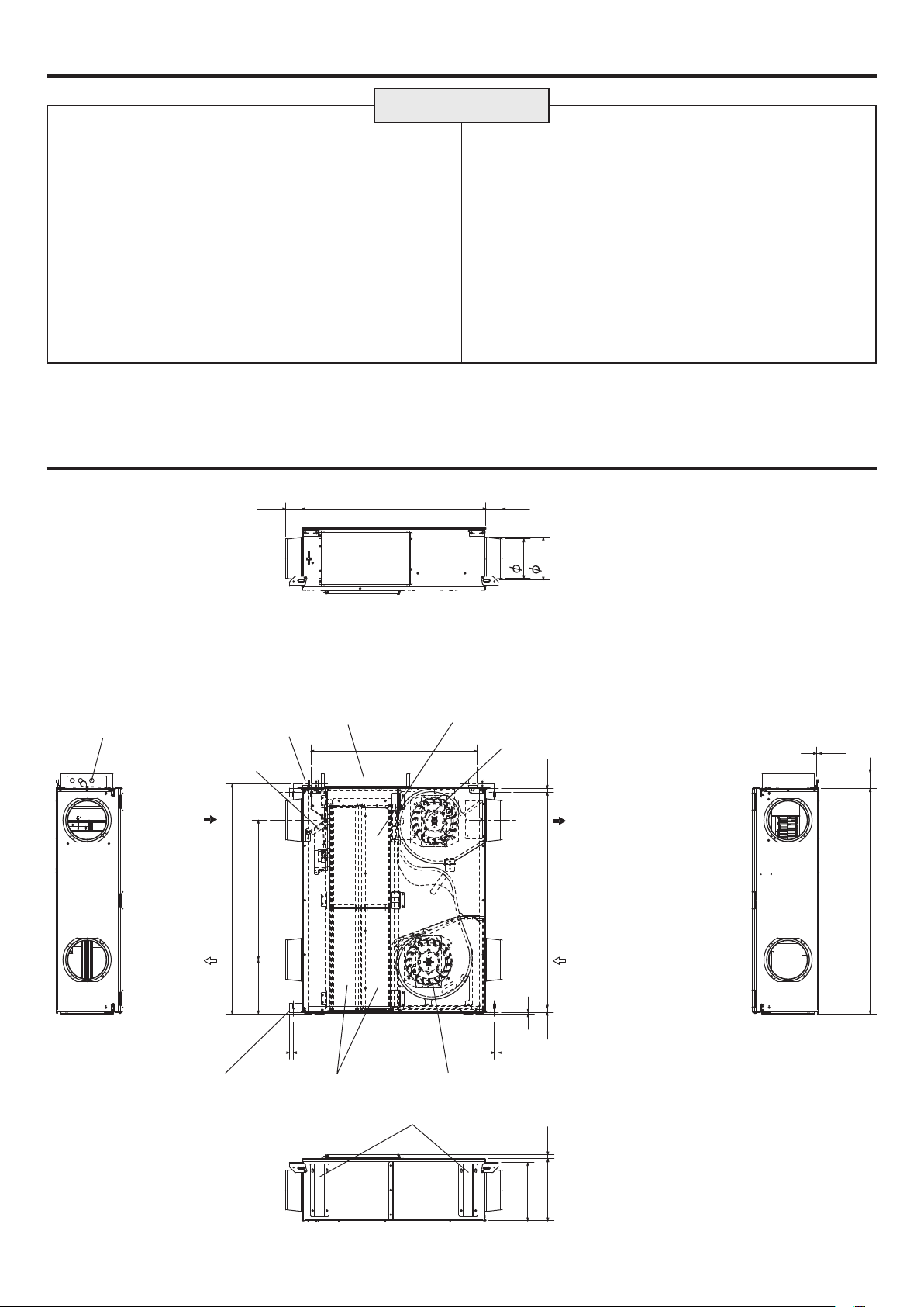
Outline darawings
CAUTION
lWhen using the product in an environment where there is a
window, or opening near the outdoor louvre , where insects
are likely to gather around the interior or exterior light , take
note that small insects may intrude into the product.
lIn a cold weather area, or others, dewing or freezing could
occur on the main unit, where the duct is connected, or other
sections, depending on the conditions of outdoor air and
indoor temperature and moisture, even if they are within
the range of operating conditions. Make sure to confirm the
operating conditions and other precautions, and do not use
the product if dewing or freezing is anticipated.
*Example of dewing condition – Outdoor air: -5°C or lower,
dew-point temperature at installation place: 10°C or higher
(When the indoor temperature is 22°C or higher with the
relative humidity higher than 50%, or other)
Accessory parts
lMounting screws.....................................x24
lDuct connecting flanges...........................x4
(double flanges at SA and EA sides)
Power cord opening
RA
(return air)
SA
(supply air)
Wall anchor point
(2-13x30 oval)
Bypass damper plate
Control box Maintenance cover
Air exhaust fan
EA
(exhaust air outlet)
OA
(outside air intake)
Ceiling suspension fixture
(4-11x10 oval)
(Air filters)
Foot plate
Air supply fanLossnay cores
Weight : 46 kg
Unit (mm)
2
Page 3
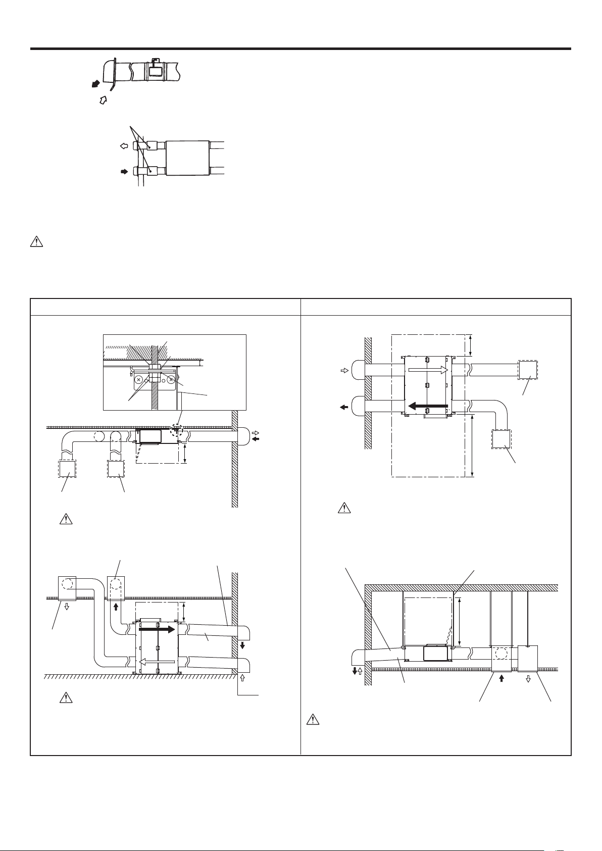
Standard installation examples
EA
(exhaust air outlet)
OA
(outside air intake)
OA (outside air intake)
EA (exhaust air outlet)
lIn a region where there is risk of freezing in winter, it is recommended
to install an Electrically operated damper, or the like, in order to
prevent the intrusion of (cold) outdoor air while Lossnay is stopped.
lThis product is designed to use horizontally as the figure or upside
down. Do not install vertically with the product suspension fixture.
lThe outside sir intake must be located where no rainwater or fog
comes in to prevent the intake of water.
Example
Electrically operated damper
(Protection against the intrusion of cold air while Lossnay is stopped in winter)
(To be provided by the customer)
Lossnay unit
<Installation horizontally><Installation vertically>
Anchor bolt
(to be provided by user)
Washer
Unit
Maintenance
space
Washer
More than
400
Supply air grille
Nut
Wall
Unit
Nut
Return air grille
Keep the unit more than 5mm away from the wall.
Downward gradient of duct:
1/30 or more (toward wall side, provide
1m or more) (to prevent rain water from
seeping in)
Maintenance
space
Unit
More than
400
SA
(supply air)
Supply air grille
Return air grille
RA
(return
air)
More
than 5
Duct
OA
(outside air intake)
EA
(exhaust air outlet)
EA
(exhaust air outlet)
OA
(outside air intake)
EA
(exhaust air outlet)
Maintenance space
Top/bottom reverse installation is not available
for this unit
Downward gradient of duct:
1/30 or more (toward wall side, provide
1m or more) (to prevent rain water from
seeping in)
Maintenance
space
Unit
Unit
More than
400
Supply air grille
More than
1200
Anchor bolt
(to be provided by user)
More than
1000
Return air grille
Floor
Unit should be on the floor by foot plate.
OA
(outside air intake)
OA
(outside air intake)
EA
(exhaust air outlet)
Duct
RA
(return air)SA(supply air)
Return air grille
Do not install the unit on the ceiling plate directly to prevent
the unit from falling, and making vibration and noise.
3
Supply air grille
Unit (mm)
Page 4

Installation method
Installing the Lossnay unit
1) Preparing the anchor bolts
Mount the washers (outer diameter of >21 mm for M10) and nuts onto
the pre-recessed anchor bolts (M10), as shown in the figure below.
Anchor bolt (M10)
Nut
Washer
Nut
2) Attaching the duct connecting flanges
Use the supplied screws to secure the duct connecting flanges to the
Lossnay unit.
Duct connecting ange
(Accessory parts)
Mounting screw
lAll mounting screws for the ceiling suspension fixture should be
tighten even if the unit is installed vertically.
CAUTION
lIf wall material is wood, tighten up by wood screws. Confirm
whether strength of wall is enough.
lWhen suspending Lossnay unit from the ceiling, do not handle it
in such a way that force will be applied to the control box.
lInstall the anchor bolts to ensure the product's weight or
earthquake load. (Correctly rated wire / chain may also be used)
4) Connecting the ducts
(1) Fasten the duct securely to the duct connecting flange, and wrap
aluminum tape (not included) around the joints so that there is no
air leakage.
(2) Suspend the ducts from the ceiling so that their weight will not be
applied to the Lossnay unit.
(3) All ducts must be covered with heat-insulating material in order to
prevent condensation from forming.
Heat-insulating
material
Outdoor
duct
Aluminum
tape
Lossnay
unit
CAUTION
lBefore attaching the duct connecting flanges, check that no
foreign matter (scraps of paper, vinyl, etc.) has found its way
inside to Lossnay unit.
lAttach the duct connecting flanges with the packing at the SA
and RA sides.
3) Mounting Lossnay unit
<Installation horizontally>
(1) Loose the screw on the ceiling suspension fixture.
(2) Turn the fixture around the loosened screw by 90 degrees to set it
at level.
(3) Fix the fixtures securely on the fan body by tightening the loosened
screw and accessory mounting screws.
(4) Hang the ceiling suspension fixtures on the anchor bolts and adjust
in such a way that Lossnay unit is level.
(5) Tighten up securely using double nuts.
<Installation vertically>
(1) Wall anchor point should be hang by M10 anchor bolt.
(2) Tighten up securely using washar (more than p26mm) and M10
nut.
Ceiling suspension xture
Mounting screw
<Installation horizontally>
Anchor bolt
Washer
Nut
Loosen
Duct connecting
ange
CAUTION
lBefore attaching the ducts, check that no (debris or any other)
foreign matter (scraps of paper, vinyl, etc.) has found its way
inside the ducts.
lDo not touch the damper plate inside Lossnay unit when
connecting the ducts.
lIf it is expected that the ambient temperature around the place
where the Lossnay unit is installed will be high during the
summer air conditioning season, it is recommended that the
indoor duct work be covered with insulation material.
Do not carry out the following types of duct construction. (Doing so
could cause a drop in the air volume and generate abnormal noises.)
• Extremely
sharp bends
• Multiple bends • Bends right next
to the outlet
• Extreme reduction
in the diameter of
the connected ducts
Wall anchor point
<Installation vertically>
Anchor bolt
Washer
Nut
Ceiling suspension xture
(Not, in use)
4
Page 5

Installation method (continued)
LINE
FILTER
Isolator
POWER SUPPLY
High voltage
(LEFT)
RED(1) BLUE(2-7)
CN15
(RIGHT)
CN16 CN17
LG-08DC
-E-M
1
3
1
7
1
4
2
1
4
4
3
7
1
1
1
1
1
5
1
6
5
1
5
1
Control Box
GREEN / YELLOW
(SA)
(EA)
M1
M2
LG-08DC
-E-C
GREEN
LED11
LED1
RED
RED
GREEN
LED2
LED3
Fan speed 1
Fan speed 2
Fan speed 3
Fan speed 4
Fan speed select
Power By-pass
condition select
Malfunction monitor output
MAX MIN
AC240V 2A AC220V 100mA
DC 24V 2A DC 5V 100mA
Operation monitor output
MAX MIN
AC240V 2A AC220V 100mA
DC 24V 2A DC 5V 100mA
WHITE(W)
BLACK(U)
RED(V)
RED
BROWN
GREEN
BLUE
BLACK
RED
BROWN
GREEN
BLUE
BLACK
BLACK(U)
RED(V)
WHITE(W)
RED
YELLOW
Reactor
Transformer
RED
YELLOW
BROWN
BLUE
CN6(red)
CN7
CN9
TM4
TM3
CN4CN5
6.3A/250V
FUSE
LS
ORANGE
ORANGE
TH2(RA)
ORANGE
ORANGE
ORANGE
ORANGE
TH1(OA)
×3
×4
SW1
TM2
BLUE
BROWN
CN1(red)
CN3
CN2
CN10
CN8(red)
CN14
TM1
220-240V 50Hz
GREEN / YELLOW
Fan speed 5
GREEN / YELLOW
PB
GM
4
1
COM
3
2
5
8
9
10
11
L
N
MARK
:Connector on PCB
:Terminal block
:Connector
L
N
PE
V
Electrical installation
With this product, the wiring installation method will vary according to the design of the system.
Perform electrical installation to meet local electrical regulations.
* Always use double insulated PVC cable for the transmission cables.
* Wiring work must be performed by qualified professionals.
* All supply circuits must be disconnected before obtaining access to the terminal devices.
Names of components in control box
Line lter
Transformer
CN14
CN10
LED2
CN8
CN9
LED3
CN2
AC Reactor
TM1
LED1
TM4
CN3
TM3
CN7
TM2
LED11
CN6
Fuse
CN1
CN15
CN16
SW1
CN17
SW2
Wire connection diagram
CAUTION
lConnect the wires shown as dotted lines.
lBe sure to connect the ground wire.
lA power supply isolator must be installed when wiring power supply to unit.
lAlways use a single pole isolator for the main switch power connection.
lAll supply circuits must be disconnected, and do not touch the components for more than 5 minutes, before obtaining access to the
terminal devices.
lIf using earth leakage breaker for isolator, rating of sensed current should be more than 10mA.
Symbol explanation
M1: Motor for exhaust fan
M2: Motor for supply fan
GM: Motor for Bypass damper
LS: Micro switch
TH1: Thermistor for outside air
TH2: Thermistor for return air
TM1: Terminal block (Power supply)
TM2: Terminal block (Fan speed selection)
TM3: Terminal block (By-pass mode selection)
TM4: Terminal block (Monitor output)
LED1(red): Power supply indicator lamp
LED2(red): Inspection indicator lamp
LED3(
green
): Inspection indicator lamp
): Inspection indicator and trial operation lamp
5
LED11(green
CN1: Connector (Power supply)
CN2: Connector (Transformer primary)
CN3: Connector (Motor for By-pass damper)
CN4: Connector (Reactor)
CN5: Connector (Reactor)
CN6: Connector (Supply fan motor)
CN7: Connector (Exhaust fan motor)
CN8: Connector (Signal for supply fan motor)
CN9: Connector (Signal for exhaust fan motor)
CN10: Connector (Signal line)
CN14: Connector (Transformer secondary)
CN15: Connector (Signal line)
CN16: Connector (Thermistor)
CN17: Connector (Micro switch)
Page 6

Installation method (continued)
PB
V
Connecting the power supply cable
1) Remove the screws and the control box cover
Control box coverScrew
2) Connecting the power supply cable
Pass the power cable through the bush* and connect to the TM1
terminal block using the round terminals. Connect the ground wire to
the ground terminal and secure tightening the bush.
(*: for PG connector or the like)
Ground wire
TM1
PG connector (customer preparation)
Power supply cable
Unit operating method
nFan speed select
Operated fan speed is followed as below table by the fan speed select
contacts.
Fan speed select contact Fan speed
All contacts : OFF OFF
1 : ON Fan speed 1
2 : ON Fan speed 2
3 : ON Fan speed 3
4 : ON Fan speed 4
5 : ON Fan speed 5
Multi contacts : ON Higher fan speed operate
CAUTION
lFan operating may be delayed from the time of contact ON
depending on the select timing.
nBy-pass condition select
By-pass damper is automatically operated based on the OA and RA
temperature.
nPower By-pass condition select
When turning on Power By-pass contact with any fan speed contacts on,
unit operation becomes power By-pass mode.
(*1)
Insert the cutting
Bush
TM3
TM2
Transmission
Cable
Bush
Cord clip
CAUTION
lAlways separate the power supply cable and the cable to the
control unit by 10 cm or more to prevent malfunctioning of the
unit.
lIf the length of the stripped power cables wires is too long, the
conductors may touch and short out.
lPower supply cable size : 1.5 mm2 or more.
(1) Refer to the wiring diagram and screw down the ground wire and
the cables to the terminal block.
(2) Secure the power supply cable with the PG connector and the
Transmission cables with the cord clip.
Upon completion of the wiring connections, replace the control box cover.
3) Connecting the cables for fan speed select and Bypass condition select
Connect the cables and the contacts as below.
Put the wires deeply to the holes of contact with pushing the button.
Confirm no unconnected wire.
com 1 2 3 4 5 PB V
TM2
Button
TM3
Ventilation priority mode
Power By-pass condition select
4) The following system configuration can be created.
Connect the necessary parts.
(1) If you would like to connect to a Electrically operated damper, etc.,
or would like to fetch operation monitor output.
(2) If you would like to fetch Malfunction monitor output.
(1) When connect to an Electrically operated damper, etc.,
or take operation monitor output:
Connect the power supply from the Electrically operated damper
to 8 and 9 of the monitor output terminal block (TM4) with
reference to the wire connection diagram.
x3
TM4
Power supply
Electrically
operated
damper
(2) When take Malfunction monitor output:
Connect to 0 and a of the monitor output terminal block (TM4)
with reference to the wire connection diagram.
x4
TM4
Power supply
Lamp or monitoring unit
Lamp or monitoring unit
Fan speed
select
contact: 12VDC 10 mA
cable for operation: 0.5mm2 to 1.0mm
maximum length: 20m from terminal block
peeling wire length: 9~10mm
CAUTION
l
Power By-pass mode is not available even if only PB contact is on. (*
lBe sure to connect Fan speed 5 wiring.
2
It is recommended to connect Malfunction monitor output to check
the malfunction externally.
1)
6
Page 7

Function settings
SW1
Trial operation
Operation monitor out put with delay function
Setting for exhaust fan in cold region operation mode
Ventilation priority mode during ventilation setting input on
Operating monitor output
By-pass auto ventilation priority setting
Auto air volume increasing during bypass setting
Not to used
SW2
Decreasing exhaust fan power
Increasing exhaust fan power
Decreasing supply fan power
Increasing supply fan power
lAll switches are OFF at factory setting.
1 Trial operation
OFF ON Operation
1 Normal operation
SW1
1 Trial operation
7 Auto air volume increasing during bypass setting
OFF ON Operation
7 Not increasing.
SW1
7
When unit is in by-pass operation except power
by-pass mode, the unit fan speed is automatically
increased 1 step.
8 Fan speed fine-tuning
ON OFF Operation
2
1
or
All supply air fan speeds are default settings.
Each supply air fan speed settings except power
bypass mode are increased.
Each supply air fan speed settings are decreased.
or
All exhaust fan speeds are default settings.
Each exhaust fan speed settings except power
bypass mode are increased.
Each exhaust fan speed settings are decreased.
SW2
2
1
2
1
2
1
4
3
4
3
4
3
4
3
2
Operation monitor out put with delay function * (TM4 89)
OFF ON Operation
2 Not available
SW1
2 Available
3
Exhaust fan speed setting in cold region operation mode *
OFF ON Operation
SW1
3 Not fixed
3 Exhaust fan : speed 5 fixed
4
Ventilation priority mode during ventilation setting input on
OFF ON Operation
SW1
4 Bypass ventilation mode fixed
4 Lossnay ventilation mode fixed
* Below 8°C, even SW1-4 is fixed any setting, ventilation mode should be Lossnay
ventilation.
5 Operating monitor output (TM4 89)
OFF ON Operation
SW1
5 Not available
5 Available
* During SW1-2 on, operating monitor out is prior to “ 2 operation motor out put with
delay function”.
6 By-pass auto ventilation priority setting
OFF ON Operation
When outdoor temperature is 17°C or higher
6
SW1
6
within 24 hours, then bypass ventilation starts by
comparison OA and RA.
When outdoor temperature is 28°C or higher
within 24 hours, then bypass ventilation starts by
comparison OA and RA.
* Operation monitor out put with delay function
Corresponds to operation mode output (TM4 89)
Supply fan with following function
- Start the output (TM4 89) 10 seconds after supply fan operates
but also when the thermistor for outside air (TH1) detect -5
lower.
- Stop the output (TM4 89) when thermistor for outside air (TH1)
detects a temperature higher than -15
malfunction of TH1.
- Lossnay continues to operate for 3 minutes, after stopping the
output (TM4 89)
- Error code is shown on the remote controller and stop the output in
case of followings.
1) TH1 detects higher than 15°C within 15 minutes after the output
starts.
2) TH1 detects -10°C or lower, 60 minutes after the output starts.
3) TH1 detects continuously 70°C or higher for more than 1 minute.
*Cold region operation mode
The unit operation is based on the measured OA temperature as
below.
Operation mode OA temperature
Normal -10°C<OA
SA intermittent -15°C<OA<-10°C
SA stopped OA<-15°C
SA : supply air EA : exhaust air OA : outside air
Continuous running Continuous running
Repeat 10min. Stop
/ 60min.
Repeat 55min. Stop
/ 5min. running
°C
or stop the supply fan or
SA fan EA fan
running
Continuous running
Continuous running
Fan speed 5 is fixed
in SA fan stopped
operation in the case
of SW1-3.
°C
or
7
Page 8

Trial operation
After the system has been installed and before the ceiling panel is installed, make sure that wires are properly connected, then test the system’s
operation.
(1) Remove the control box cover.
(2) Turn the trial operation switch (SW1-1) “On”.
lLED11 will be on with the Fan speed 1 setting and with By-pass ventilation operating for 1 min.
Then, it will change to energy recovery ventilation mode.
(3) Turn the trial operation switch (SW1-1) “Off
(4) Install the cover in its original position on the control box.
Trouble shooting
Cause of failure
Supply fan over current failure Twice - Once -
Exhaust fan over current failure - Twice - Once
Shortage of power supply voltage Twice - 3times -
Over voltage of power supply Twice - 4times -
Supply fan motor operating failure Twice - 5times -
Exhaust fan motor operating failure - Twice - 5times
Supply fan motor sensor failure Twice - 6 or 7times -
Exhaust fan motor sensor failure - Twice - 6 or 7times
Communication failure between
upper and lower PCB
Damper failure 3times - - -
Outside air sensor failure 4times - - -
Room air sensor failure 5times - - -
External interlocked unit failure 8times - - -
If troubles occur as above, turn off all fan speed contacts immediately and contact to your dealer.
The unit may not operate properly if the power supply voltage is lower than the rating voltage. (220-240V)
”.
LED indication (Blinking)
Small PCB (right) Large PCB (left)
LED1
(red)
9times 9times 9times 9times
LED11
(green)
LED2
(red)
LED3
(green)
Motor operation
stop
running
HEAD OFFICE: TOKYO BLDG., 2-7-3, MARUNOUCHI, CHIYODA-KU, TOKYO 100-8310, JAPAN
AUTHORIZED REPRESENTATIVE IN EU:
MITSUBISHI ELECTRIC EUROPE B.V.
HARMAN HOUSE, 1 GEORGE STREET, UXBRIDGE, MIDDLESEX UB8 1QQ, U.K.
 Loading...