

Page 1
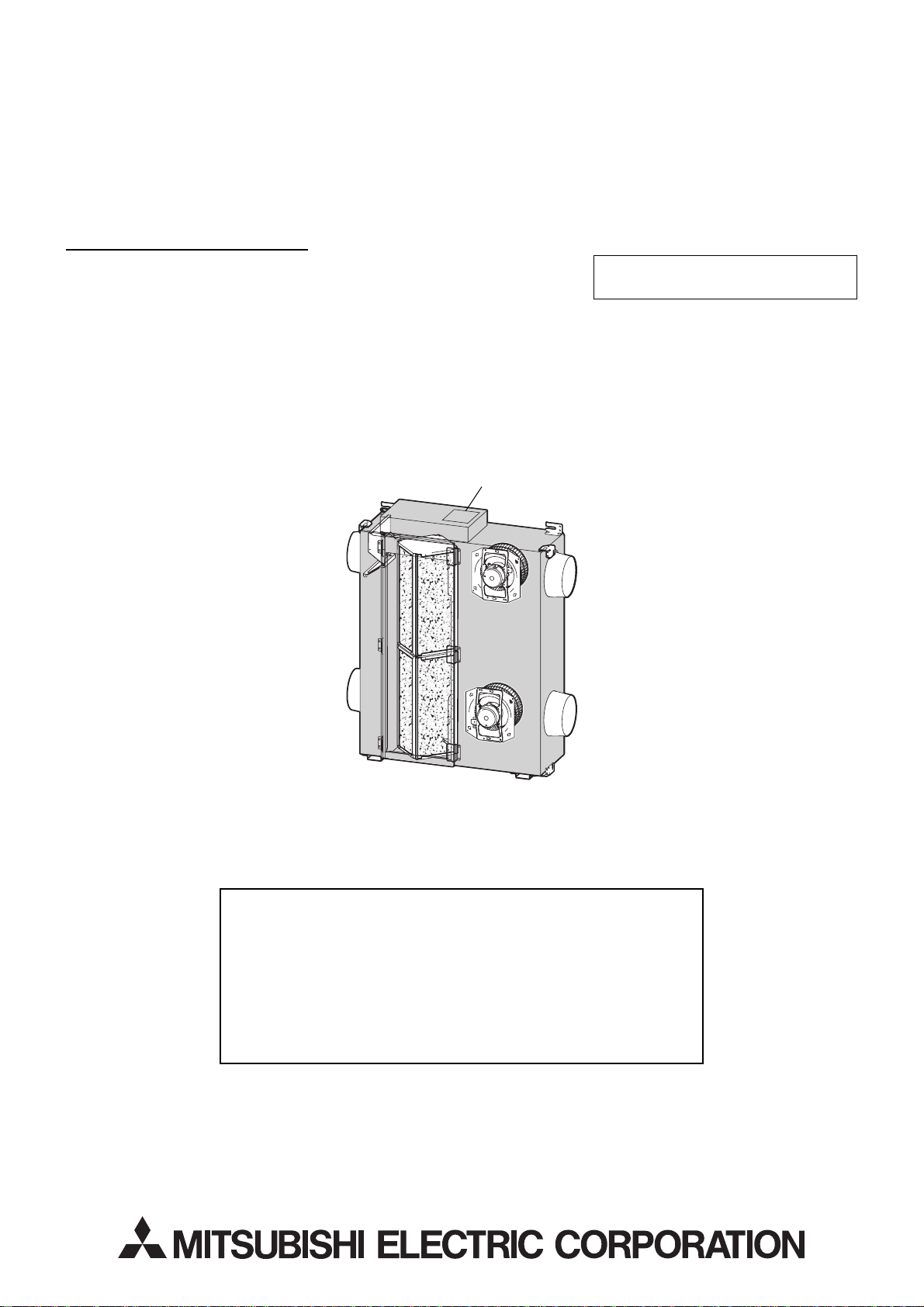
LOSSNAY
HAND BOOK
Model: LGH-50RSDC-E
August 2009 No. U162-A
FOR DEALERS
Nameplate
Repair work should be performed by
the manufacturer, its service agent or
similarly qualified person in order to
avoid hazards.
Page 2

Contents
1. Safety precautions ................................................................. 3
2. Names of components ......................................................... 4
3. Specifications ....................................................................... 5
4. Outside dimensions ............................................................... 6
5. Electrical wiring diagram ...................................................... 7
6. Basic circuit diagrams ....................................................... 8-9
7. Fundamentals of operation ............................................ 10-15
8. Troubleshooting ............................................................. 16-22
9. Overhaul procedure ....................................................... 23-27
10. Parts catalog ................................................................. 28-34
Page 3
1. Safety precautions
Please be sure to read the following precautions thoroughly before commencing with the maintenance work, and
conduct the inspection and repair of the product in a safe manner.
The types and levels of danger that may arise if the product is handled incorrectly are described by using the
warning symbols shown below.
Incorrect handling of the product may result in serious injury
Warning
or death.
Electric shock
If you must inspect the circuitry while the power is
on, do not touch the live parts.
(Failure to heed this warning may result
in electric shock.)
Caution for
electric shock
Modification is prohibited
Do not modify the product.
(Failure to heed this warning may result
in electric shock, fire and/or injury.)
Prohibited
Proper electric work
Use the electric wires designated for electric work,
and conduct electric work in accordance with the
"Electric Installation Engineering Standard", the
"Indoor Wiring Regulations" and the installation
instructions.
(Improper connection or wiring installation
may result in electric shock and/or fire.)
Be sure to follow
this instruction.
Turn off the power supply
Be sure to shut off the power supply isolator before
disassembling the product for repair.
(Failure to heed this warning may result
in electric shock.)
Be sure to follow
this instruction.
Use proper parts and tools
For repair, be sure to use the parts listed in the
service parts list of the applicable model and use the
proper tools.
(Failure to heed this warning may result in
electric shock, fire and/or bodily injury.)
Be sure to follow
this instruction.
Replace damaged and/or degraded parts
Be sure to replace the power-supply cord and lead
wires in the event that they are damaged and/or
degraded.
(Failure to heed this warning may result
in electric shock and/or fire.)
Be sure to follow
this instruction.
Check insulation
Upon completing repair work, always measure the
insulation resistance. Verify that it is at least 10 M
(with a 500 V DC insulation resistance tester), and
then turn on the power.
(Inadequate insulation may cause electric
shock.)
Be sure to follow
this instruction.
Incorrect handling of the product may result in serious injury
Caution
Caution for injury
Do not conduct any work at a location where you do
or damage to properties including buildings and equipment.
Wear gloves
Wear gloves when conducting work.
not have a sure footing.
(Failure to heed this caution may result in
(Failure to heed this caution may result in
a fall.)
Prohibited
injury to your hands from sharp metal or
other edges.)
Be sure to follow
this instruction.
Request for repair
Inspect the grounding, and repair it if incomplete. Make sure that a power supply isolator or an overload
protection device is being installed, if not, recommend the dealer to install one.
Make sure that the product operates properly upon completion of repair. Clean the product as well as the
surrounding area, and then notify the customer of the completion of repair.
3
Page 4
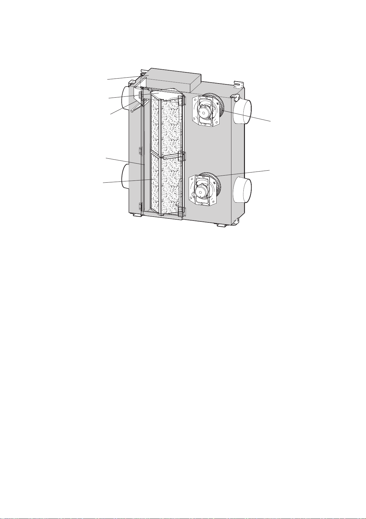
2. Names of components
Control box
Lossnay core
Damper plate
Maintenance cover
Air filter
(4 filters)
Air exhaust fan
(EA fan)
Air supply fan
(SA fan)
4
Page 5
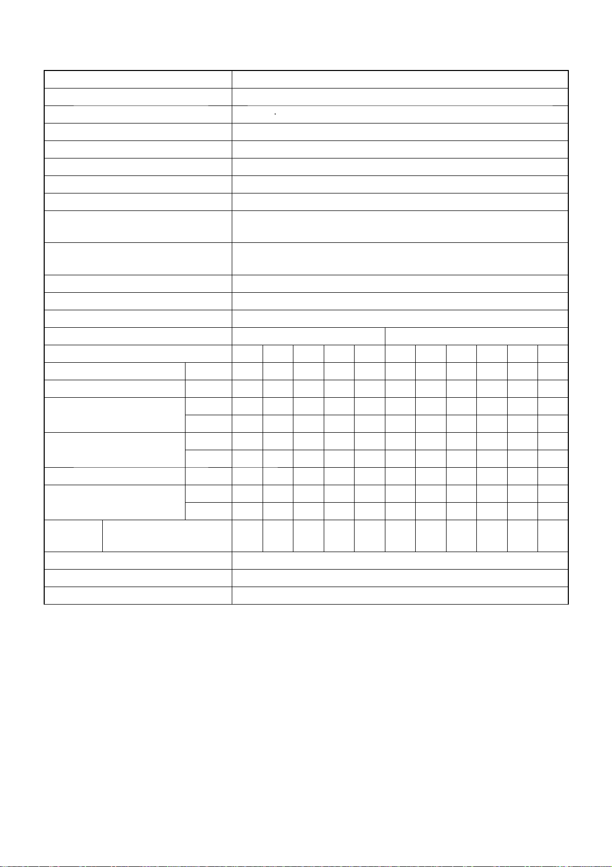
3. Specifi cations
Model LGH-50RSDC-E
Heat exchange system Air-to-air Total heat exchange (sensible heat + latent heat exchange)
Heat exchange element material Partition spacing plate-special treated paper
Cladding Galvanized steel sheet
Heat insulating material Self-extinguishing urethane foam
Motor DC brushless motor. Two units
Blower 220 mm diameter. Centrifugal fan
Filter material Non-woven fabrics fi lter (Gravitational method 82%, EU-G3)
Applicable air condition of setting environment
Applicable air condition range of outdoor
and indoor
The setting air condition shall be between -10°C to 40°C, 80%RH or less.
OA temperature shall be -15°C to 40°C, 80%RH or less, with general air
conditioning room environment.
Functions
Lossnay ventilation fi ve speeds / Bypass ventilation (fi ve speeds + power)
Weight 48 kg
Frequency / Power source 50 Hz / Single phase 220-240 V
Ventilation mode
Fan speed (230 V) 12345
Lossnay (Energy recovery) ventilation
Power
Bypass ventilation
12345
Current [A] 1.17 0.67 0.35 0.20 0.13 1.80 1.20 0.70 0.35 0.20 0.13
Power Consumption [W] 165 90 41 22 14 265 164 90 40 21 14
3
/h] 395 305 215 144 90 468 395 305 215 144 90
[m
Air volume
[l/s] 110 85 60 40 25 130 110 85 60 40 25
2O] 10.2 6.1 3.1 1.5 0.7 13.8 10.2 6.1 3.1 1.5 0.7
[mmH
External static pressure
[Pa] 100 60 30 15 7 135 100 60 30 15 7
Temperature exchange effi ciency
Enthalpy exchange
effi ciency [%]
Noise [dB]
Measured at 1.5 m under the center
of panel in an anechoic chamber
[%] 77.5 81.5 85.5 88 90 - - - - - Heating 71 75 79 82 84 - - - - - Cooling 68 72.5 77 80.5 83 - - - - - -
31 26.5 21 18 18 35 31 26.5 21 18 18
Starting current 2.5 A or less
Insulation resistance 10 M
or more (500 V megger)
Dielectric strength AC 1500 V 1 minute
5
Page 6
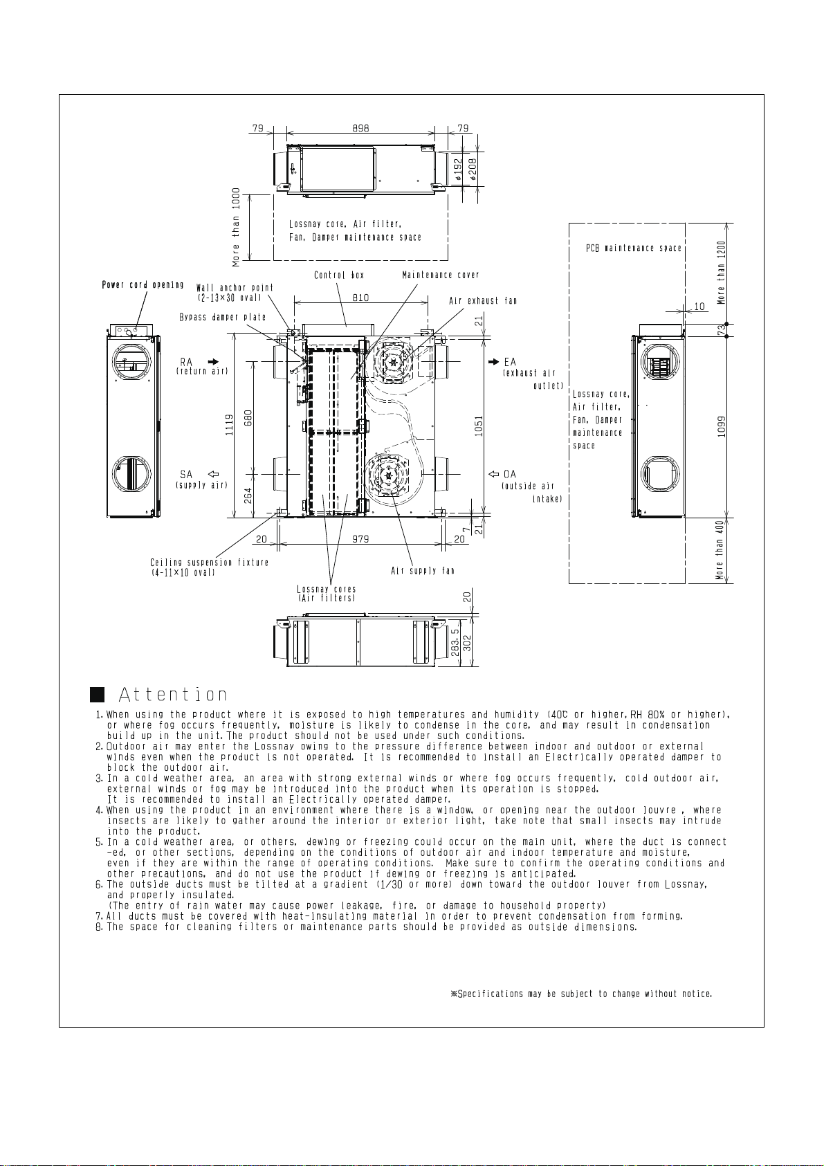
4. Outside dimensions
6
Unit (mm)
Page 7
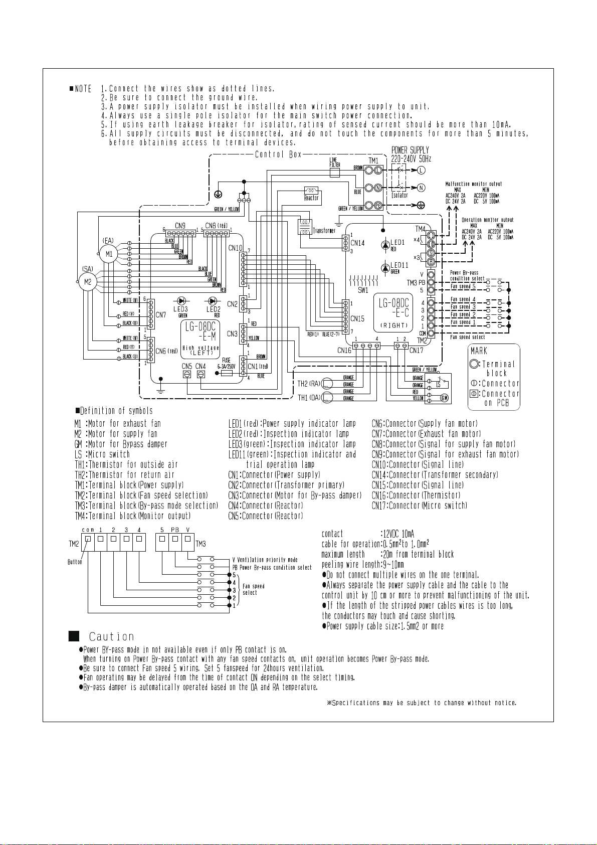
5. Electrical wiring diagram
7
Page 8
6. Basic circuit diagrams
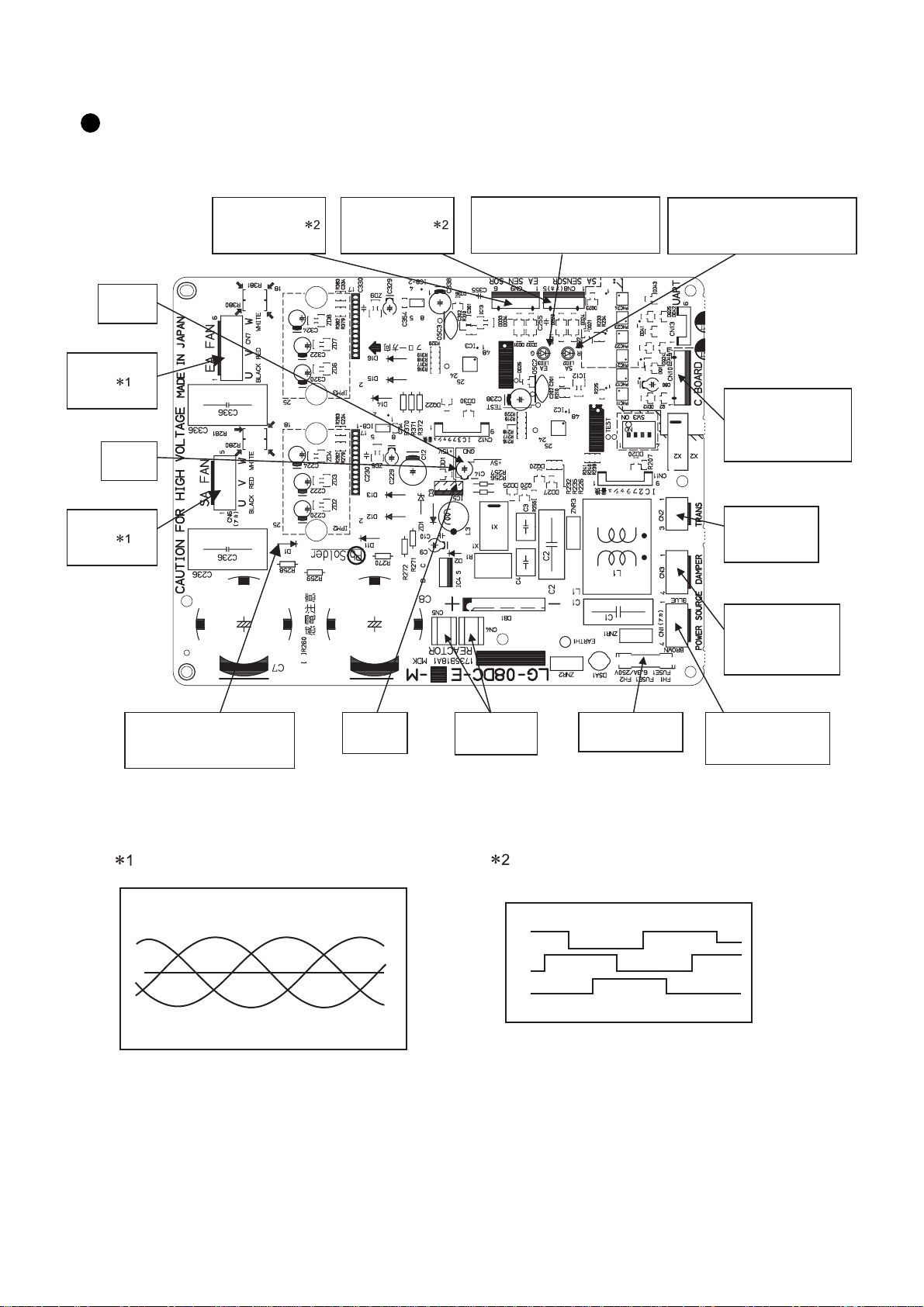
Circuit board diagrams and check points
(1) Large PCB (printed circuit board) (Left)
5 V DC
(C14)
EA fan drive
output
(CN7)
GND
(C14)
SA fan drive
output
(CN6)
EA fan motor
sensor signal
(CN9)
SA fan motor
sensor signal
(CN8)
LED 3 (green)
䍃During EA fan operation: lit
䍃During an error: blinking
LED 2 (red)
䍃During SA fan operation: lit
䍃During an error: blinking
Communication
signal between
the circuit boards.
(CN10)
Transformer
input
(CN2)
Motor for
Bypass damper
220-240 V AC
(CN3)
300-340 V DC
(D1)
Fan drive power supply
15 V DC
(IC5)
Current waveform of the fan drive output
(Current of each line)
Reactor
(CN4, CN5)
Voltage waveform of the fan motor sensor signal
(Voltage between the lead wires of the
Fuse
(6.3 A / 250 V)
connectors 2, 3, 4 and GND)
U Line current V Line current W Line current
Although the current cycle and value varies
with the operational status, each current waveform
is a sine wave with a phase difference by 120 degrees.
Note) Noise is included in the actual waveform.
CAUTION
●
5 V
U
V
W
The voltage cycle varies with the operational
status (rotational frequency).
Each signal has 50% duty cycle of H (5 V) and L (0 V),
and there is a phase difference by 120 degrees.
Note) Noise is included in the actual waveform.
0 V
Live parts of the large PCB is not insulated from the power supply.
Even after turning off the power, the capacitors on the circuit boards are still charged.
Wait more than 5 minutes before servicing.
Power supply
220-240 V 50 Hz
(CN1)
8
Page 9
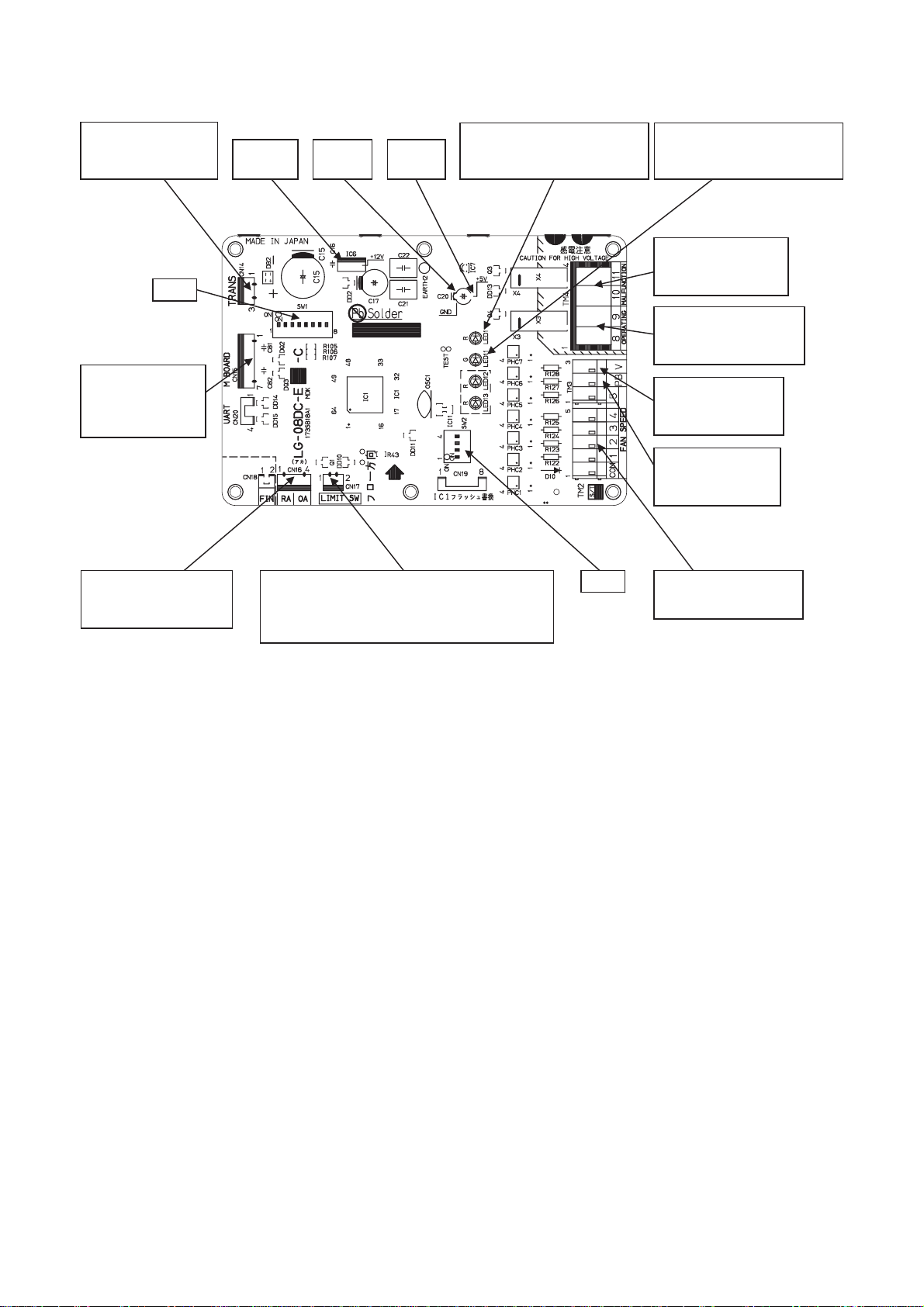
(2) Small PCB (right)
Transformer output
11 V to 20 V AC
(CN14)
SW1
Communication
signal between
the circuit boards.
(CN15)
Thermistor
(return air, outside air)
(CN16)
LED 1 (red)
12 V DC
(IC6)
Damper position detector
(CN17)
䍃during energy recovery ventilation: 12 V DC
䍃during bypass ventilation: 0 V
GND
(C20)
5 V DC
(C20)
䍃Normal: lit
䍃During an error: blinking
SW2
LED 11 (green)
䍃During trial operation: lit
䍃During an error: blinking
During an error: 0 Ω
Normal: Open
(TM4 10, 11)
During operation: 0 Ω
When stopped: Open
(TM4 8, 9)
Ventilation priority
mode selection
(TM3 V)
Power bypass
condition selection
(TM3 PB)
Fan speed selection
(TM2 1-4, TM3 5)
9
Page 10
7. Fundamentals of operation
Description of the PCB
(1) Air volume control
Fan speed selection
(TM2, TM3)
Operation
(Reference value under rated static pressure)
(m3/h) (l/s)
All contacts : OFF Stop 0 0
Air volume
Speed 1 (Contact between 1 and COM) : ON
395 110
Speed 2 (Contact between 2 and COM) : ON 305 85
Speed 3 (Contact between 3 and COM) : ON 215 60
Running
Speed 4 (Contact between 4 and COM) : ON 144 40
Speed 5 (Contact between 5 and COM) : ON 90 25
Power bypass (Contact between PB and COM) : ON 468 130
1 Power bypass will be enabled when any of fan speed contacts (1 to 5) are ON. (The fan will not operate
when only the power bypass contact is turned ON.)
2 It needs 5 seconds to change air volume (including OFF) after the fan speed is selected.
3 When multiple fan speeds are selected simultaneously, the higher fan speed will be performed.
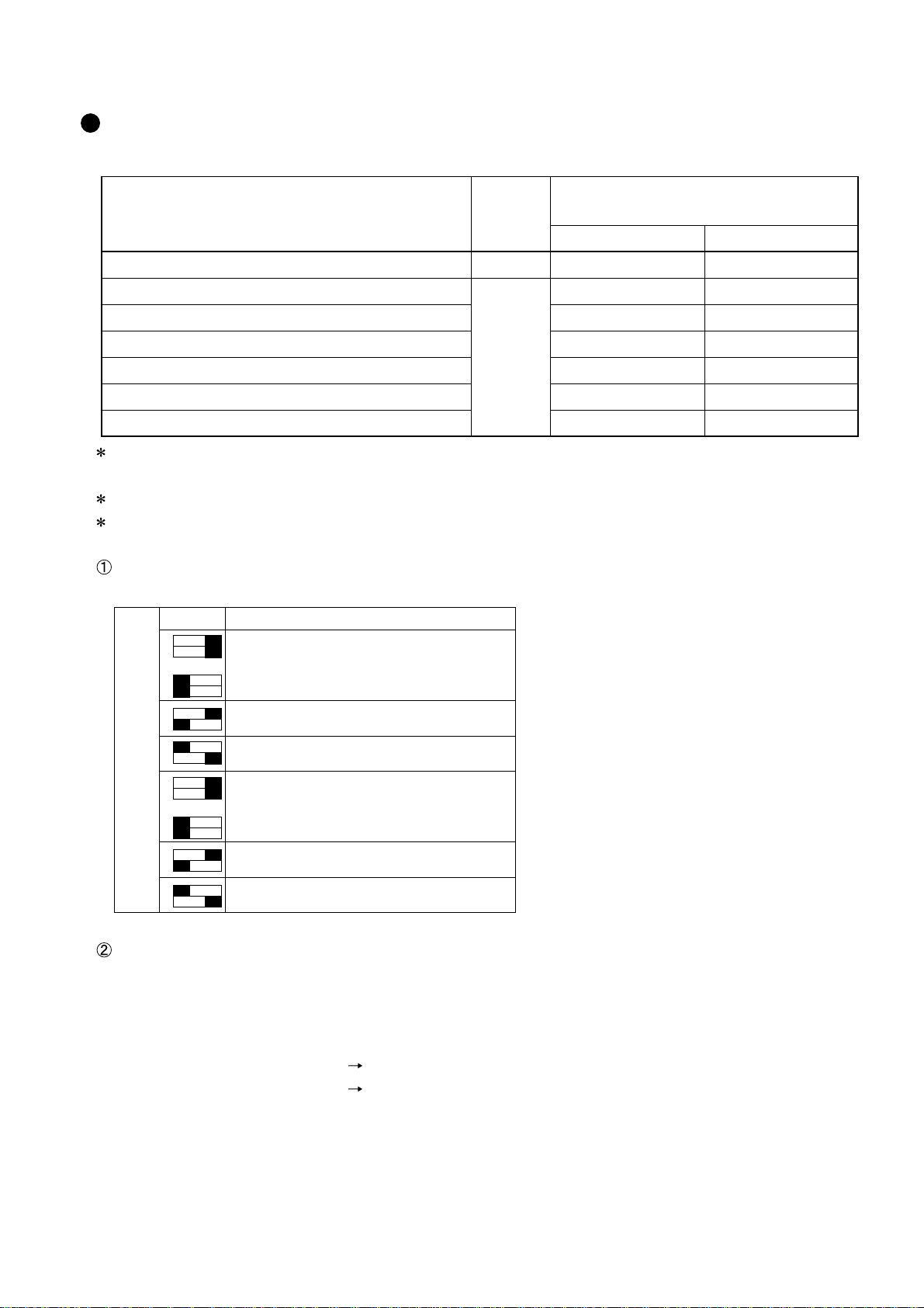
Fan speed fi ne-tuning
Fan speed can be fi ne-tuned by the dip switch SW 2 on the circuit board.
ON OFF Operation
2
1
or
All supply air fan speeds are default settings.
Each of the supply air fan speed settings except
power bypass mode is increased.
Each of the supply air fan speed settings is
decreased.
or
All exhaust fan speeds are default settings.
Each of the exhaust fan speed settings except
power bypass mode is increased.
Each of the exhaust fan speed settings is
decreased.
SW 2
2
1
2
1
2
1
4
3
4
3
4
3
4
3
Automatic air volume increasing during bypass setting
Fan speed will automatically increase 1 step higher than its present speed if both conditions are met:
• The dip switch SW 1-7 on the circuit board is ON.
• Operation mode is switched to bypass ventilation from energy recovery ventilation (with a summer criteria)
in automatic ventilation mode.
Example 1 : Speed 3 operation Speed 2 operation
Example 2 : Speed 1 operation Power bypass operation
( If the operation mode is switched to energy recovery ventilation from bypass ventilation, fan speed will
return to its original speed.)
─10─
Page 11
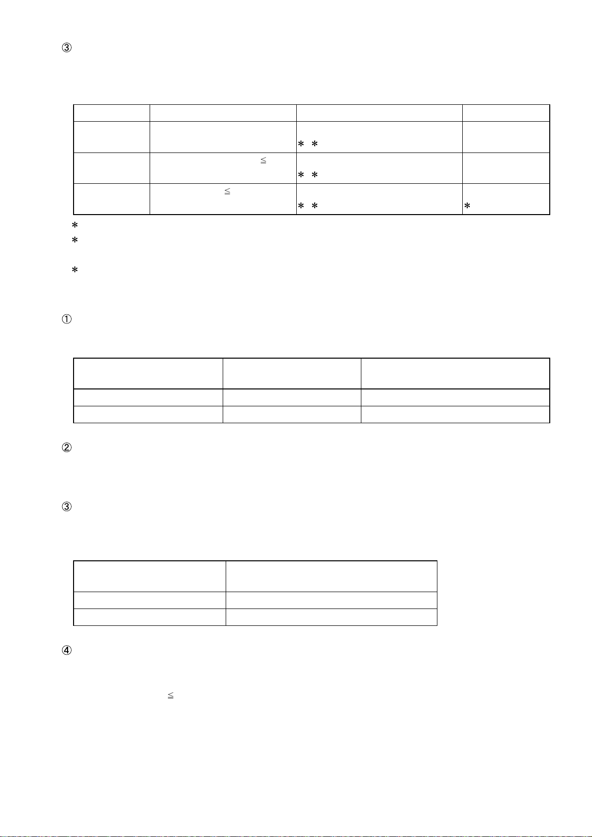
Cold region operation mode
When using the unit in cold region, set the air supply (SA)fan in the SA intermittent operation mode to prevent the energy recovery core from freezing. The fan operation is based on the measured outside air (OA)
temperature as below.
Operation mode OA temperature SA fan EA fan
Normal -10°C < OA temperature Continuous running
1
2
SA intermittent -15°C <OA temperature -10°C
SA stopped OA temperature -15°C Repeat 55 min. stop / 5 min. running
1 The operation mode will be decided 5 minutes after the normal operation during startup.
2 The running condition does not change while the SA fan stops or 1 minute after startup. (OA temperature
is voided.)
3 When the switch SW 1-3 is on, the EA fan operates at fan speed 5 during 55-minute stop of the SA fan.
Repeat 10 min. stop / 60 min. running
1 2
1 2
Continuous running
Continuous running
Continuous running
3
(2) Damper motor control
Automatic ventilation mode
Automatic ventilation algorithm patterns are switched by the OA • RA (return air) thermistor and function setting switch SW 1-6.
Function setting switch SW1-6
OFF (factory setting) 17°C or higher Automatic ventilation pattern 1 (chart 1)
ON 28°C or higher Automatic ventilation pattern 2 (chart 2)
Power bypass mode
When turning on the TM3 PB contact with any fan speed contacts (1 to 5) on, operation mode will be
switched to bypass ventilation. Then, fan speed will be also increased to Power bypass speed.
Ventilation priority mode
When turning on the TM3 V contact with any fan speed contacts (1 to 5) on, operation mode (energy recovery or bypass) can be fi xed by the function setting switch SW 1-4. (Fan speed will not be changed in the
bypass ventilation mode.)
Function setting switch SW1-4 Ventilation priority mode
OFF (factory setting) Bypass ventilation fi xed
ON Energy recovery ventilation fi xed
Prohibition of the bypass ventilation
In case of the situations below, bypass ventilation will be disabled, and energy recovery ventilation setting
will be activated.
a. OA temperature 8°C (for dew condensation prevention)
b. OA • RA thermistor failure.
OA temperature criteria
in the summer season
Automatic ventilation algorithm
─11─
Page 12

Automatic ventilation algorithm temperature chart
< Pattern 1>
Chart 1. Automatic ventilation algorithm temperature chart during the switch SW 1-6 OFF setting.
When an outdoor temperature has not reached 17ºC
within 24 hours
Undetermined area
30
28
26
24
22
20
Energy recovery
18
16
14
12
10
Outdoor temperature °C
8
6
ventilation
6 8 10 12 14 16 18 20 22 24 26 28 30
Indoor temperature °C
ventilation
Bypass
When an outdoor temperature has reached 17ºC or higher
within 24 hours
Bypass
Undetermined area
30
28
26
24
22
20
Energy recovery
18
16
14
12
10
Outdoor temperature °C
8
6
ventilation
6 8 10 12 14 16 18 20 22 24 26 28 30
Indoor temperature °C
ventilation
<Pattern 2>
Chart 2. Automatic ventilation algorithm temperature chart during the switch SW 1-6 ON setting.
When an outdoor temperature has not reached 28ºC
within 24 hours
When an outdoor temperature has reached 28ºC or higher
within 24 hours
Bypass
Undetermined area
30
28
26
24
22
20
Energy recovery
18
16
14
12
10
Outdoor temperature °C
8
6
ventilation
6 8 10 12 14 16 18 20 22 24 26 28 30
Indoor temperature °C
ventilation
Undetermined area
30
28
26
24
22
20
Energy recovery
18
16
14
12
10
Outdoor temperature °C
8
6
ventilation
6 8 10 12 14 16 18 20 22 24 26 28 30
Indoor temperature °C
Undetermined area
When operation starts under this condition, energy recovery ventilation will be activated.
When this condition is reached after operation starts, the current ventilation mode is maintained.
Bypass
ventilation
─12─
Page 13

(3) Operation monitor output
When the function setting switch SW 1-2 (for operation monitor output with delay function) is set to OFF, and
the switch SW 1-5 (for operation monitor output) is set to ON, the operation monitor signal can be output from
the monitor terminal block
SW 1-2 OFF
SW 1-5 ON
Signal type Uncharged a-contact
Contact specifi cations
and (TM4) on the circuit board.
Maximum load
Minimum load 5 V DC 100 mA
220-240 V AC 2 A
24 V DC 2 A
Operation
Stopping Monitor output : Off (contact : open)
Running Monitor output : On (contact : close)
(4) Operation monitor output with delay function
When the function setting switch SW 1-2 (for operation monitor output with delay function) is set to ON, the operation monitor signal from the monitor terminal block and (TM4) on the circuit board is shown as below.
SW 1-2 ON
Signal type Uncharged a-contact
220-240 V AC 2 A
24 V DC 2 A
Monitor output : On (contact : close) 10 seconds after air
supply fan operates
Contact specifi cations
Operation
Maximum load
Minimum load 5 V DC 100 mA
OA temperature
OA temperature 15°C Monitor output : Off (contact : open)
The fan continues to operate for 3 minutes, after operation monitor output has been
OFF by the Lossnay stopping control.
-5°C
(5) Malfunction monitor output
The malfunction monitor signal can be output from the monitor terminal block and (TM4) on the circuit
board.
Signal type Uncharged a-contact
Contact specifi cations
Maximum load
Minimum load 5 V DC 100 mA
Normal Monitor output : Off (contact : open)
Operation
During an error Monitor output : On (contact : close)
─13─
220-240 V AC 2 A
24 V DC 2 A
Page 14

(6) Trial operation function
This is a function for operating the Lossnay without external signals (contact signals). With this function, con-
necting condition of the AC power supply line and the wirings can be confi rmed. Also, the Lossnay can be
forced to operate in case of system down.
How to set Turn on the trial operation switch SW 1-1.
SA fan operation Speed 1
EA fan operation Speed 1
Operation mode Energy recovery ventilation, after 1 minute bypass ventilation
LED 11 Lit
Operation monitor output
(TM4 and )
When SW 1-2 (Operation monitor output with delay function) is ON, or
SW 1-5 (Operation monitor output) is ON,
Monitor output : On (contact : close)
(7) LED display
Small PCB (right) Large PCB (left)
LED Display Condition LED Display Condition
1 No power supplied
Unlit
LED 1 (red)
LED 11 (green)
1 When one of LED 1 and LED 11 is blinking, the other one will be unlit.
2 In case multiple errors have occurred at the same time, each LED will blink simultaneously.
Lit Power supplied Lit SA fan running
Blinking Error Blinking Error
Unlit 1 Normal
Lit In trial operation Lit EA fan running
Blinking Error Blinking Error
LED 2 (red)
LED 3 (green)
Unlit SA fan stopping
Unlit EA fan stopping
─14─
Page 15

(8) Function setting switches
SW1
Trial operation
Operation monitor output with delay function
Setting for exhaust fan in cold region operation mode
Ventilation priority mode during ventilation setting input on
Operation monitor output
Bypass auto ventilation priority setting
Automatic air volume increasing during bypass setting
Not to used
SW2
Decreasing exhaust fan power
Increasing exhaust fan power
Decreasing supply fan power
Increasing supply fan power
All switches are OFF at factory setting.
1 Trial operation (Refer to (6) (page 14).)
OFF ON Operation
SW1
1 Normal operation
1 Trial operation
7 Automatic air volume increasing during bypass setting
OFF ON Operation
7 Not increasing.
SW1
7
When unit is in bypass operation except power
bypass mode, the unit fan speed is automatically
increased 1 step.
8 Fan speed fine-tuning
ON OFF Operation
2
1
or
All supply air fan speeds are default settings.
Each of the supply air fan speed settings except
power bypass mode is increased.
Each of the supply air fan speed settings is
decreased.
or
All exhaust fan speeds are default settings.
Each of the exhaust fan speed settings except
power bypass mode is increased.
Each of the exhaust fan speed settings is
decreased.
SW2
2
1
2
1
2
1
4
3
4
3
4
3
4
3
2
Operation monitor output with delay function (TM4 )
OFF ON Operation
SW1
2 Not available
2 Available (Refer to (4) (page 13).)
3
Exhaust fan speed setting in cold region operation mode
(Refer to (1) (page 11).)
OFF ON Operation
SW1
3 Not fixed
3 Exhaust fan : speed 5 fixed
4
Ventilation priority mode during ventilation setting input on
(Refer to (2) (page 11).)
OFF ON Operation
SW1
4 Bypass ventilation mode fixed
4 Lossnay (Energy recovery) ventilation mode fixed
* Below 8°C, even SW1-4 is fixed any setting, ventilation mode should be Lossnay
(Energy recovery) ventilation.
5 Operation monitor output (TM4
OFF ON Operation
SW1
5 Not available
5 Available (Refer to (3) (page 13).)
* During SW1-2 on, operation monitor output is prior to “ 2 operation monitor output
with delay function”.
)
6 Bypass automatic ventilation priority setting (Refer to (2)
(page 12).)
OFF ON Operation
6
SW1
6
When outdoor temperature is 17°C or higher
within 24 hours, then bypass ventilation starts by
comparison OA and RA.
When outdoor temperature is 28°C or higher
within 24 hours, then bypass ventilation starts by
comparison OA and RA.
─15─
Page 16

8. T roubleshooting
Work precautions
• When removing or touching a transformer, printed circuit board or other parts, make sure to turn off the
power supply isolator. Even after disconnecting the power supply isolator, the voltage is still high in the capacitors on the printed circuit boards. Wait more than 5 minutes, and make sure a voltage is low by using a
tester, before servicing.
• When removing the circuit board, always hold it at both ends and remove carefully so as not to apply force to
the surface mounted parts.
• When removing the circuit board, be careful of the metal edges on the board.
• When removing or inserting the connectors for the circuit board, hold the entire housing section. Never pull
on the lead wires.
• When servicing, be sure to recreate the malfunction two or three times before starting repairs.
• When reconnecting the power supply, wait more than 5 minutes after power-off, and then turn it on again.
• If it is thought that there is a printed circuit board malfunction, check for disconnected wires in the print pattern, burnt parts or discoloration.
• If the printed circuit board is replaced, make sure that the switch settings on the new board are the same as
the old board.
Part names used in the following text correspond to those listed in the parts catalog.
(1) Checkpoints for installation condition
No. Checkpoints
1 Do the wiring diameters and capacity of the motor breaker and the ground-fault interrupter meet specifi -
cations?
2 Is the specifi ed power (220-240 V AC 50 Hz) supplied to the power terminal (TM1)?
3 Do the wirings for the fan speed and bypass condition selections meet specifi cations?
• Contact: 12 V DC 10 mA
• Diameter of cables : 0.5 mm
• Maximum length : 20 m from terminal block
• Wire peeling length : 9-10 mm
4 Are the wirings for fan speed and bypass condition selections correct?
5 Are the wires for fan speed and bypass condition selections more than 10 cm away from the power sup-
ply cable?
6 Are the connected terminal blocks of the wires for fan speed and bypass condition selections correct?
(TM2 1-4 and TM3 5 are for fan speed selection. TM3 PB and V are for bypass condition selection.)
7 Is each wire securely connected to the terminal blocks?
8 Are external signals correctly input to TM2 and TM3 on the circuit board?
9 Is the output capacity of the operation and malfunction monitors within rated range?
Operation monitor output : Maximum 220-240 V AC/ 24 V DC 2 A, minimum 5 V DC 100 mA
Malfunction monitor output : Maximum 220-240 V AC/ 24 V DC 2 A, minimum 5 V DC 100 mA
2
to 1.0 mm2
─16─
Page 17

(2) Troubleshooting and repair method
When any LEDs on the circuit boards are blinking
The type of failure is shown by the number of blinking times of LED 1 (red), LED 11 (green), LED 2 (red) and
LED 3 (green) on the circuit boards. The LED blink interval is 0.25 seconds for both lit and unlit. The display
duration is approximately 5 seconds.
0.25s 0.25s0.25s
Lit
Unlit
5s
Failure display example (2 blinks)
Checklist of LED failure displays
LED 1
LED 1 1
LED 2
(red)
2
blinks
-
2
blinks
2
blinks
2
blinks
(green)
-
2
blinks
-
-
-
(red)
1
blink
-
3
blinks
4
blinks
5
blinks
LED 3
(green)
-
1
blink
-
-
-
Symptom Cause Corrective action
SA fan overcurrent failure
EA fan overcurrent failure
Fan drive
voltage failure
(Undervoltage)
Fan drive
voltage error
(Overvoltage)
SA fan operation failure
Overcurrent occurred
at the SA fan motor.
SA fan motor malfunction
Large circuit board
malfunction
Overcurrent occurred
at the EA fan motor.
EA fan motor malfunction
Large circuit board
malfunction
The power supply
voltage is low (150 V
AC or lower).
Large circuit board
malfunction
The power supply
voltage is high (320 V
AC or higher).
Large circuit board
malfunction
The SA fan does not
rotate properly.
SA fan motor wire
connection error
SA fan motor malfunction
SA fan motor sensor
malfunction
Large circuit board
malfunction
Turn off the power supply, wait more than 5
minutes, and then turn it on again.
Check the coil resistance of the fan motor.
If it has a defect, replace the fan motor.
Replace the circuit board if none of above
related actions works.
Turn off the power supply, wait more than 5
minutes, and then turn it on again.
Check the coil resistance of the fan motor.
If it has a defect, replace the fan motor.
Replace the circuit board if none of above
related actions works.
Check the power supply voltage.
(220-240 V AC 50 Hz)
Replace the circuit board if none of above
related actions works.
Check the power supply voltage.
(220-240 V AC 50 Hz)
Replace the circuit board if none of above
related actions works.
Check whether the fan turns by hand.
Check the wiring of the connector (CN6) on
the circuit board and the fan motor.
Check the coil resistance of the fan motor.
If it has a defect, replace the fan motor.
Check the signal voltage of the fan motor sensor. If it has a defect, replace the fan motor.
Replace the circuit board if none of above
related actions works.
In case multiple errors have occurred at the same time, each LED will blink simultaneously.
When reconnecting the power supply, wait more than 5 minutes after power-off, and then turn it on again.
─17─
Page 18

LED 1
LED 1 1
LED 2
LED 3
(red)
-
2
blinks
-
(green)
blinks
blinks
2
-
2
(red)
-
6 or 7
blinks
-
(green)
5
blinks
-
6 or 7
blinks
9
blinks9 blinks9 blinks9 blinks
Symptom Cause Corrective action
EA fan operation failure
SA fan motor
sensor failure
EA fan motor
sensor failure
Communication
failure between
the circuit
boards 1
The EA fan does not
rotate properly.
EA fan motor wire
connection error
EA fan motor malfunction
EA fan motor sensor
malfunction
Large circuit board
malfunction
Wire connection error
of SA fan motor sensor
SA fan motor sensor
malfunction
Large circuit board
malfunction
Wire connection error
of EA fan motor sensor
EA fan motor sensor
malfunction
Large circuit board
malfunction
Connection error
between the circuit
boards
The external signal
wires and power supply cable are too close.
Connection error of
transformer
Transformer malfunction
Connection error of
reactor
Check whether the fan turns by hand.
Check the wiring of the connector (CN7) on
the circuit board and the fan motor.
Check the coil resistance of the fan motor.
If it has a defect, replace the fan motor.
Check the signal voltage of the fan motor sensor. If it has a defect, replace the fan motor.
Replace the circuit board if none of above
related actions works.
Check the wiring of the connector (CN8) on
the circuit board and the fan motor sensor.
Check the signal voltage of the fan motor sensor. If it has a defect, replace the fan motor.
Replace the circuit board if none of above
related actions works.
Check the wiring of the connector (CN9) on
the circuit board and the fan motor sensor.
Check the signal voltage of the fan motor sensor. If it has a defect, replace the fan motor.
Replace the circuit board if none of above
related actions works.
Check the connections of the connectors
(CN10, CN15) on the circuit boards.
Keep the wires for fan speed and bypass
condition selections more than 10 cm away
from the power supply cable.
Check the connection of the connectors
(CN2, CN14) on the circuit boards.
Check the output of the transformer. If it has
a defect, replace the transformer.
Check the connection of the connectors
(CN4, CN5) on the circuit board.
Reactor malfunction Check the resistance of the reactor. If it is
open, replace the reactor.
Circuit boards malfunction
Replace both circuit boards if none of above
related actions works.
1 Each LED does not blink simultaneously in some cases.
In case multiple errors have occurred at the same time, each LED will blink simultaneously.
When reconnecting the power supply, wait more than 5 minutes after power-off, and then turn it on again.
─18─
Page 19

LED 1
(red)
3
blinks
4
blinks
5
blinks
8
blinks
LED 1 1
LED 2
LED 3
(green)
(red)
(green)
---
---
---
---
Symptom Cause Corrective action
Damper failure Damper plate opera-
tion error
Remove the rod, and then check whether
the damper plate moves by hand.
For removing the rod, open the maintenance
cover and remove the guards from the unit.
Wire connection error
of the damper unit
Check the wiring of the connectors (CN3,
CN17) on the circuit boards and the damper
unit.
Connection error
between the circuit
Check the connection of the connectors
(CN10, CN15) on the circuit boards.
boards
OA thermistor
failure
RA thermistor
failure
External device error
(when the
switch SW 1-2
is ON)
Connector connection
error of thermistor
Thermistor malfunction
Connector connection
error of thermistor
Thermistor malfunction
The following conditions developed.
•
OA temperature is
still -10°C or lower, 60
minutes after the TM4
Check the wiring of the connector (CN16) on
the circuit board and the thermistor.
Check the resistance of the thermistor.
If it has a defect, replace the thermistor.
Check the wiring of the connector (CN16) on
the circuit board and the thermistor.
Check the resistance of the thermistor.
If it has a defect, replace the thermistor.
When external devices are connected,
check the external devices.
When external devices are not connected,
check the switch SW 1-2.
8,9 output started.
•
OA temperature is 15
°C or higher within 15
minutes after the TM4
8,9 output started.
In case multiple errors have occurred at the same time, each LED will blink simultaneously.
When reconnecting the power supply, wait more than 5 minutes after power-off, and then turn it on again.
LED displays (Normal)
LED 1
LED 1 1
LED 2
(red)
Lit
2
-
LED 3
(green)
(red)
(green)
---
Lit
2
--
Power supplying to the circuit board Lit when the power is supplying to the circuit
Trial operation Lit during trial operation (SW 1-1 ON).
Contents Descriptions
board.
- - Lit - SA fan operation Lit during the SA fan operation.
- - - Lit EA fan operation Lit during the EA fan operation.
2 When one of LED 1 and LED 11 is blinking (during an error), the other one will be unlit.
All LEDs are temporarily lit just after power-on.
─19─
Page 20

When the unit does not operate or operates irregularly
No. Symptom Cause Corrective action
1 The fans do not
operate.
Power is not supplied to the unit. Check the power supply.
(200-240 V AC 50 Hz)
Power supply voltage is out of rated
range.
• Improper connection or wiring of the
external signals.
• The type of external signals does not
match the connected terminal block.
Check the power supply.
(220-240 V AC 50 Hz)
Check the connections of the external signal
wires and the terminal blocks (TM2, TM3).
TM2 1-4 and TM3 5 are for fan speed selection.
TM3 PB is for bypass condition selection.
TM3 V is for ventilation priority mode.
The type of external signals is incorrect.
Check the type of external signals.
(Uncharged a-contact)
The external device signals are not input. Check the external devices.
The signal cables from the external devices are longer than specifi ed.
Check the wiring length of the signal
cables. (Make sure the wiring length from
the external devices is within 20 m.)
The external signal wires and the power
supply cable are too close.
Keep the wires for fan speed and bypass
condition selections more than 10 cm
away from the power supply cable.
2• The fans do not
stop.
•
The fan speed
does not change.
Malfunction of the circuit board, or the fan
motor
The trial operation switch SW 1-1 is ON. Check the trial operation switch SW 1-1.
The external device signals are input. Check the external devices.
The external signal wires and the power
supply cable are too close.
See the "Checklist of LED failure displays"
(page 17).
Keep the wires for fan speed and bypass
condition selections more than 10 cm
away from the power supply cable.
The signal cables from the external devices are longer than specifi ed.
Check the wiring length of the signal
cables. (Make sure the wiring length from
the external devices is within 20 m.)
3 Air volume chang-
es by itself.
The function setting switch SW 1-7
(Automatic air volume increasing during
bypass setting) is ON.
If energy recovery ventilation mode is au-
tomatically switched to bypass ventilation
with the switch SW 1-7 is ON, fan speed
will increase 1 step higher than its present
speed (with a summer criteria).
If the operation mode is switched to en-
ergy recovery ventilation, fan speed will
return to its original speed.
Refer to 7. (1) (page 10).
(This is not a failure.)
4 The SA fan pe-
riodically stops
operating.
When -15°C < OA temperature -10°C,
•
the SA fan regularly stops for 10 minutes
to prevent the Lossnay core from freez-
Refer to 7. (1) (page 11).
(This is not a failure.)
ing.
• When OA temperature is -15°C or lower,
The SA fan stops to prevent the Lossnay
core from freezing.
─20─
Page 21

No. Symptom Cause Corrective action
5 The SA fan pe-
riodically stops
operating, and the
EA fan air volume
decreases.
6 After operation
has been stopped,
the fan continues
to run for a while.
When OA temperature is -15°C or lower,
the SA fan stops operating to prevent the
Lossnay core from freezing.
Then, the EA fan runs at speed 5 if the
switch SW 1-3 is ON.
The function setting switch SW 1-2
(Operation monitor output with delay function) is ON.
Refer to 7. (1) (page 11).
(This is not a failure.)
When the switch SW 1-2 is ON, the fan
continues to operate for 3 minutes after
Lossnay operation has been stopped.
Refer to 7. (4) (page 13).
(This is not a failure.)
7 The damper plate
does not operate.
When OA temperature is 8°C or lower, energy recovery ventilation mode is turned on.
Check the OA temperature.
Trial operation switch SW 1-1 is ON. Turn off the trial operation switch SW 1-1.
When the bypass
condition selection signal (TM3
PB, V) is being
used.
Malfunction of the circuit board, or the
damper motor
The type of external signals does not
match the connected terminal block.
The type of external signals is incorrect.
See the "Checklist of LED failure displays"
(page 17).
Check the connections of the external sig-
nal wires and the terminal blocks (TM2,
TM3). (TM3 PB or V is for bypass condi-
tion selection)
Check the type of external signals.
(Uncharged a-contact)
8 Operation moni-
tor or malfunction
monitor is not correctly output.
9 LED 1 on the cir-
cuit board is not lit
in spite of power
supplying.
The external device signals are not input. Check the external devices.
The signal cables from the external devices
are longer than specifi ed.
Check the wiring length of the signal
cables. (Make sure the wiring length from
the external devices is within 20 m.)
The external signal wires and the power
supply cable are too close.
Keep the wires for fan speed and bypass
condition selections more than 10 cm
away from the power supply cable.
The function setting switch SW 1-4
(Ventilation priority mode during ventilation setting input on) is ON.
When the switch SW 1-4 and TM3 V input
is ON, operation mode is fi xed in energy
recovery ventilation.
Refer to 7. (2) (page 11).
The connected terminal block is incorrect.
•
• Check the connections of the terminal
blocks (TM4).
• Connection error
• The function setting switch SW 1-2 or
SW 1-5 is not set to ON.
• Check the switch SW 1-2 (Operation
monitor output with delay function) or
SW 1-5 (Operation monitor output).
Connection error of the power supply lead
wires
Check the wiring of the connector (CN1)
and the power supply terminal block
(TM1) on the circuit board.
Connection error of the transformer Check the connection of the connectors
(CN2 and CN14) on the circuit board.
Transformer malfunction Check the transformer output. If it has a
defect, replace the transformer.
Disconnection of the fuse Replace the circuit board.
Malfunction of the small circuit board Replace the circuit board if none of above
related actions works.
─21─
Page 22

Temperature and thermistor resistance table
Temperature
(°C)
-30
-20 32.8 18 6.5
-19 31.3 19 6.2
-18 29.8 20 6.0
-17 28.4 21 5.8
-16 27.1 22 5.6
-15 25.9 23 5.4
-14 24.7 24 5.2
-13 23.5 25 5.0
-12 22.5 26 4.8
-11 21.5 27 4.7
-10 20.6 28 4.5
-9 19.6 29 4.3
-8 18.8 30 4.2
-7 18.0 31 4.0
Resistance value (kΩ)
(TYP)
53.9 -
∞
Temperature
(°C)
16 7.0
17 6.7
Resistance value (kΩ)
(TYP)
-6 17.2 32 3.9
-5 16.4 33 3.8
-4 15.7 34 3.6
-3 15.1 35 3.5
-2 14.4 36 3.4
-1 13.9 37 3.3
0 13.3 38 3.2
1 12.8 39 3.1
2 12.2 40 3.0
3 11.7 41 2.9
4 11.2 42 2.8
5 10.8 43 2.7
6 10.4 44 2.6
7 9.9 45 2.5
8 9.5 46 2.4
9 9.2 47 2.4
10 8.8 48 2.3
11 8.5 49 2.2
12 8.1 50 2.1
13 7.8
14 7.5 90 0-0.7
15 7.3
─22─
Page 23

9. Overhaul procedure
Work precautions
• When touching the electric components such as circuit boards and fan motors, do not touch the components
for more than 5 minutes after power-off, and then start servicing.
• Before replacing parts, repair troubled sections according to the instructions described in the troubleshooting.
• When servicing, always keep proper footing.
• When servicing, make sure that the cord is pulled out of the outlet, or the power supply isolator is off if no
mains connector is built in the product, so as no electrical shock or injury to occur. Pay suffi cient attention
when working on the product.
• Always connect the power wire properly.
• After completing repairs, confi rm that the main unit operates normally.
• Always wear gloves when servicing.
Part names used in the following text correspond to those listed in the parts catalog.
(1) Turning power off
Shutdown the unit.
Turn off the power supply isolator on the distribution board.
Precaution
All supply circuit must be disconnected, and do not touch
the components for more than 5 minutes, before obtaining access to the terminal devices.
(2) Fan parts
Open the maintenance cover.
Maintenance cover
Unscrew the fi xing screws (25 PTT screws 4 x 8, indicated by ) for the casing (upper).
Unscrew the fi xing screws (four screws indicated by , and two special screws indicated by ) for the guards.
Precaution
DO NOT REMOVE the maintenance cover, although the picture shows the unit without the cover for easy understanding. When you remove the casing (upper), close the maintenance cover after unscrewing all the screws.
Casing (upper)
─23─
Guard
(Maintenance cover)
Page 24

Remove the casing (upper).
Air Exhaust (EA) fan
Unscrew the screws (two PTT screws 4 x 8, indicated by
) for the connector cover next to the EA fan.
EA fan SA fan
These parts are drawn translucently to show inner parts.
Disconnect all the connectors for the fans.
Unscrew the screws (six PTT screws 5 x 10, indicated
by ).
EA fan
Connectors for the EA fan and SA fan
Power supply wiring
Signal wiring
─24─
Page 25

Air Supply (SA) fan
Unscrew the screws (six PTT screws 5 x 10, indicated
by ).
(3) Circuit board parts
Unscrew the screws (four screws, indicated by ) for the
control cover.
When replacing the lead wires or damper parts, unscrew the fi xing screws (two PTT screws 4 x 8, indicated
by ) for the fi x plate.
Fix plate
Lead wires
(power)
Lead wires
(signal)
*GM=Geared Motor
Lead wires
(GM)
Transformer Reactor
─25─
Terminal blockCircuit board
Page 26

(4) Lossnay core
Unscrew the screws (two screws, indicated by ) for the core holder.
Core holder
Draw the Lossnay core from the unit by holding the
handles.
Lossnay core Handles
(5) Damper parts and Damper motor
Remove the fi x plate for the lead wires and disconnect the wires from the circuit board. (Refer to (3) (page 25)).
Unscrew the screws (two screws, indicated by ) for the damper, and draw the damper from the unit.
Damper GM cover
─26─
A
B
Page 27

Unscrew the screws (three screws, indicated by ) for
the GM cover.
Remove the GM cover.
Unscrew the screws (two screws, indicated by ) for the
damper motor.
GM cover
When assembling
Assemble the unit in the reverse order of disassembly.
Always make sure that the unit works properly when
reassembled.
Damper motor (GM)
─27─
Page 28

10. Parts catalog
Please note the following when using the parts catalog.
1. When ordering parts, always indicate the part number, part name, and the number of
parts required.
2. Parts are not always available, and it may take time for you to receive them.
3. There may be specifi cation improvements.
4. Specifi cations are correct as of August 2009.
5. Parts marked are critical for safety. To maintain safety and performance, always
replace these parts with the parts prescribed.
6. The numbers that are circled in the exploded view are the same as the reference
number for the part being indicated.
Description of screw abbreviations
Screw
Abbreviation Description
PC screw Cross recess fl at head machine screw
PRC screw Cross recess oval head machine screw
PP screw Cross recess pan head machine screw
SW · PP screw Cross recess pan head screw with spring washer
PPT screw Cross recess tapping screw
PCT screw Cross recess fl at head tapping screw
PTT screw Cross recess truss head tapping screw
PT screw Cross recess truss head machine screw
SET screw Slotted head stop screw
SQ · SET screw Square head stop screw
P · SET screw Pan head stop screw
PMT screw Primer truss head screw
HS · SET screw Hexagon head stop screw
P · R · W screw Cross recess round wood screw
4
Screw diameter Length
×
16
P · C · W screw Cross recess fl at head wood screw
P · R · C · W screw Cross recess round and fl at wood screw
R · W screw Slotted round wood screw
PW · PP screw Cross recess pan head screw with small washer
SW-PW · PP screw Cross recess pan head machine screw with spring washer and fl at washer
─28─
Page 29

Model LGH-50RSDC-E
No. Parts No. Name of part Critical Remarks Price
1. H00 000 487 PTT screw 4×8 99
2. R50 028 610 Flange 4
3. Y55 001 223 Cord clip 1
4. H00 000 244 PT screw 6×12 4
5. R50 095 380 Hanger 2
6. Y50 123 369 Wiring diagram 1
7. R50 399 223 Cord clip 2
8. R50 399 224 Cord clip 8
9. K81 540 384 Fix plate 2
10. H00 000 390 PT screw 5×10 4
11. K81 540 385 Fix plate 2
12. Y50 123 722 Fix piece 3
13. Y50 057 344 Wire 1
14. Y50 123 721 Maintenance cover 1
15. Y50 123 830 Casing(upper) 1
16. Y50 123 717 Core holder 1
17. Y50 123 723 Guard 2
18. H00 000 332 PTT screw 4×10 4
19. A33 391 045 Special screw 4×12 2 Black
20. Y50 123 345 Fix piece 3
21. Y50 123 344 Hinge 3
22. Y50 123 724 Lossnay core 2
23. Y50 123 730 Filter 4
Q'ty
pcs/unit
for safety
29
Page 30

1
*
*
1
2
3
4
5
10
11
6
4
5
2
*
1
10
9
8
7
2
9
12
10
11
10
2
*
1
18
19
16
17
23
22
15
14
23
13
23
1
23
17
*
21
22
1
24pcs.
1
20
* shows accessory parts.
─30─
Page 31

Model LGH-50RSDC-E
No. Parts No. Name of part Critical Remarks Price
31. R50 488 713 Motor fix plate 2
32. Y50 123 453 Motor 1
33. Y50 031 608 Flinger 2
34. K81 417 102 U ring 2
35. M45 649 226 Bush 5
36. M35 164 224 Cord clip 10
37. Y50 123 708 Fan base 1
38. H00 056 075 Spring washer(4) 2
39. H00 189 007 PTT screw 5×10 20
40. Y50 123 720 Connector cover 1
41. D41 123 223 Lead wire clip 2
42. Y50 123 710 Connector case 1
43. Y50 123 711 Fix plate(earth) 1
44. M34 706 465 Special washer 2 φ10
45. R50 542 480 Centrifugal fan 2 φ220
46. M34 398 077 Tab washer 2
47. R50 331 067 Special nut(8) 2 Left-handed
48. Y50 123 718 Fan casing 1
49. Y50 123 709 Fix pieces 2
50. Y50 123 454 Motor 1
51. H00 172 076 Lock washer 1
52. Y50 123 712 Motor fix plate 1
53. Y50 123 713 Separator 1
54. Y50 123 719 Fan casing 1
Q'ty
pcs/unit
for safety
31
Page 32

35
49
36
36
37
36
34
35
1
33
40
35
35
41
41
42
1
44
43
45
1
1
48
47
46
Air exhaust fan assembly
32
1
31
1
1
39
1
38
52
1
51
36
50
31
1
38
1
39
33
39
34
A
54
1
45
44
─32─
53
47
46
Air supply fan assembly
A
49
1
Page 33

Model LGH-50RSDC-E
No. Parts No. Name of part Critical Remarks Price
61. Y50 123 732 Damper fix plate 1
62. Y50 123 727 Fix plate 1
63. Y50 123 156 Pull spring 1
64. D40 072 225 Bush 1
65. Y50 123 729 Damper 1
66. Y50 123 716 Damper support 1
67. Y50 115 225 Bush 1
68. Y50 123 726 GM cover 1
69. Y50 061 260 Damper motor (GM) 1 AC220・240V
70. R50 054 225 Special bush 2
71. Y50 123 725 GM fix plate 1
72. Y50 123 728 Rod 1
73. M31 234 089 Special bush 2
74. H00 000 003 PP screw 4×8 2
75. Y50 123 715 Control cover 1
76. Y50 123 221 Lead wire 1
77. D41 006 363 Cord band 1
78. Y50 123 172 Circuit board 1 LG-08DC-E
79. Y50 123 714 Fix plate 1
80. K83 223 225 Bush 3
81. Y50 138 216 Transformer 1 AC230V
82. Y50 123 179 Reactor 1
83. H00 000 349 PT screw 4×8 9
84. M13 100 242 Terminal block 1 3P
85. H00 154 005 PPT screw 4×12 1
86. H00 011 008 PT screw 4×8(BS) 1
87. H00 013 076 Lock washer(4) 2
88. D42 019 095 Spacer 3
89. X40 139 095 Spacer 10
90. Y50 123 733 Circuit fix plate 1
91. Y50 123 216 Lead wire(GM) 1
92. Y50 123 214 Lead wire(sigunal) 1
93. Y50 123 213 Lead wire(poewr) 1
94. Y50 123 731 Fix plate 1
Q'ty
pcs/unit
for safety
33
Page 34

61
62
63
64
66
65
67
68
69
70
7
8
70
71
1
72
73
73
10
35
83
8
79
81
80
74
80
82
80
83
84
85
86
1
36
87
88
83
89
94
90
75
76
77
78
91
1
92
93
─34─
Page 35

Printed in Japan
June, 2009
24 <MEE>
Page 36

Revision record
Revision Date Overview
U162-1
A 2009-08-19 Page 33
Parts No. of No.63 was R50 069 156.
 Loading...