

Page 1
Mitsubishi Lossnay for Business Use
Model
LGH-40ES-E
Installation Instructions (For use by dealer/ contractor)
This product needs to be installed properly in order to demonstrate the designed functions to the maximum as
well as to secure the safety. Please make sure to read this installation manual before starting the installation.
■Installation must be made by a dealer or installation contractor. Please note that improper installation could cause
malfunction or accident.
Separate booklet “Instruction Manual” is provided for the customer.
The booklet and this manual must be handed over to the customer after completing the installation.
English
Safety Precautions
●The following signs indicate that death or serious injury may be caused a failure to heed the precautions
described below and the resultant mishandling of the product.
Do not modify or disassemble.
(It could cause fire, electric shock or injury.)
Both the main unit and the wall switch should not be installed where it is highly humid, like bathroom, or other..
(It could cause electric shock or earth leakage.)
Use the specified power supply and voltage. (Use of incorrect power supply or voltage could cause fire or electric shock.)
Select a place with sufficient strength and install the main unit securely. (It could cause injury if it drops off.)
Wiring work must be implemented safely and securely in accordance with the engineering standards and the extension wiring
rules for electrical equipment. (Poor connection or improper wiring work could cause electric shock or fire.)
Install an earth leakage circuit breaker at the power supply side for protection against the earth leakage.
(It could cause fire if earth leakage occurs.)
Use the specified wires and connect them securely to prevent disengagement when they are pulled.
(If a defect is in the connection, there is possibility of fire.)
Select an adequate place for the opening to introduce outdoor air, where it will not inhale the exhaust fumes like combustion
gas, or others, and there is no risk of blockage by snow fall, or others.
(Shortage of fresh air could put the room in the state of oxygen deficiency.)
Duct made of steel must be installed with care not to be connected electrically with metals such as the metal lath, wire
lath, stainless steel plate, or others. (It could cause fire when the earth leakage occurs.)
Do not use at a place where exposed to naked flames or in environment with fume of oil or organic solvent.
(It could cause fire.)
Put on gloves during installation. (It could cause injury.)
Make sure the circuit breaker is turned off on the power distribution panel when operation is stopped for a long period of
time after the installation. (It could cause electric shock, earth leakage or fire as a result of deteriorated insulation.)
Always use the specified suspension bolts, nuts and washer.
(Use of hardware with insufficient strength could result in the dropping of product.)
1
Page 2
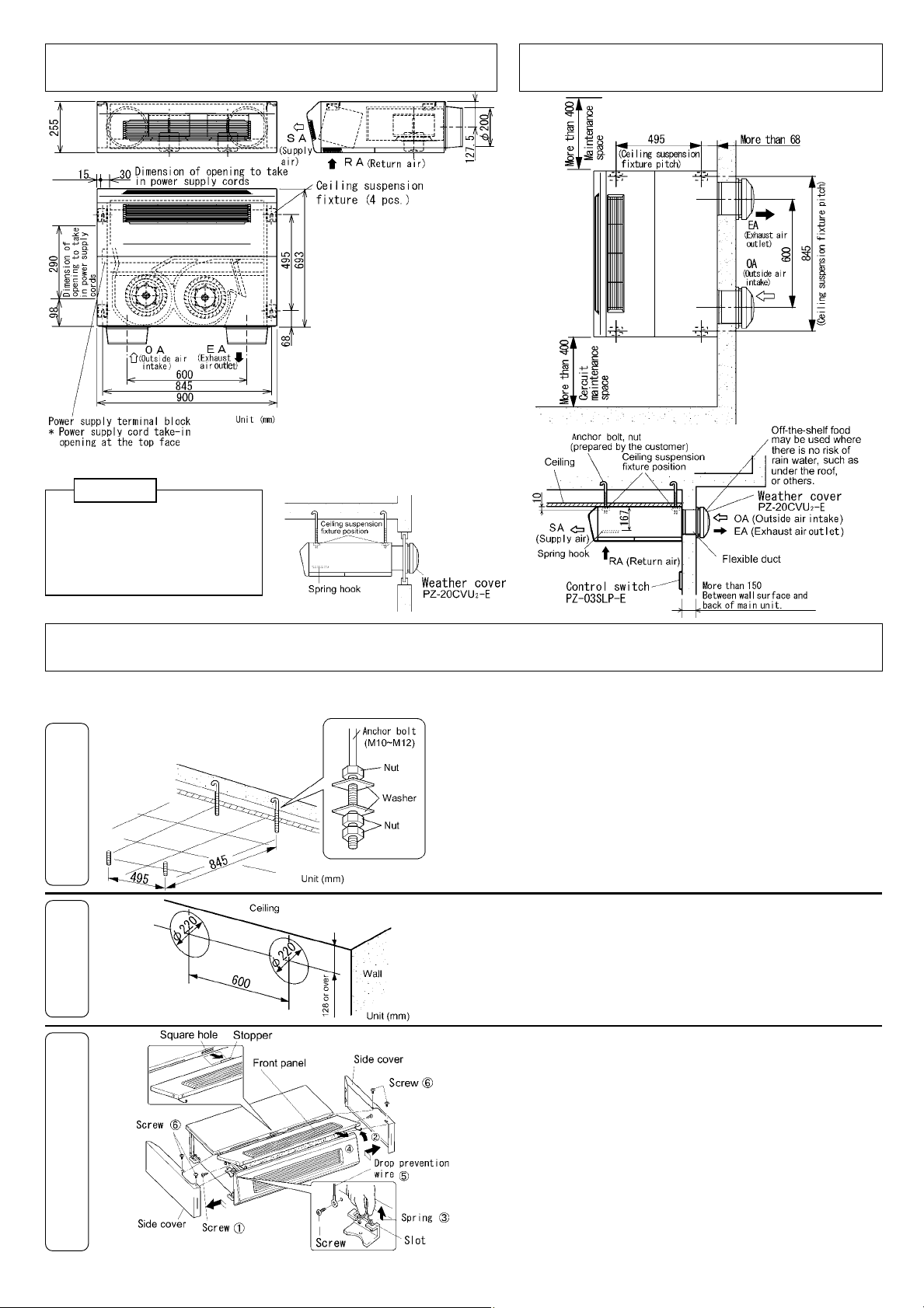
Outline Drawings Sample inst allations
n
Attention
・Provide heat insulation to prevent
moisture condensation along the two
outside ducts(fresh-air intake and
exhaust-air outlet).
・Do not use vent caps or round hoods i
places directly exposed to rain.
■When a window is changed into an
aluminum board and duct piping is
carried out.
Inst allation method
Preparation for installation
1
2
Embed off-the-shelf anchor bolts (M10~M12) at the ceiling
suspension fixture mounting positions beforehand, referring to the
outside dimension drawing and the example of installation as shown
above.
1. Adjust the length of anchor bolt so that double nuts can be
used af ter installing the main unit, as shown at left. (If it
is too long,
it could interfere with the spring hook, or others.)
2.Install off-the-shelf washers (□32 mm or larger for M10, □36
mm or larger for M12) and nuts as shown at left.
Drill holes for suction and exhaust air.
●Drill holes of φ220 on the wall referring to the outside
dimension drawing and the example of installation.
※Pitches of suspension bolts and suction/exhaust holes must be
adjusted within ±2 mm.
3
Removal of front panel and side cover
① Remove the screws at each side on the front panel.
② Raise this side of the front panel.
③ Hold and disengage the spring from the slot. (2 places)
④ Draw out the front panel in the arrow direction.
⑤ Remove screws (2 pcs.), which are securing the drop prevention
wires on the main unit.
⑥ Remove screws at right and left (2 pcs. each) and remove the
side covers.
2
Page 3

Inst allation method (continued)
Duct connection
English
Installation of main unit
Duct connection
1.Cut an off-the-shelf duct at a length that will not come off the
external wall. (Duct should be cut not to extend into the surface
of the external wall beyond 10 mm.)
2.Insert the cut duct (φ200) in the duct connection flange and lock
with an off-the-shelf drilling tapping screw.
3.Seal the gap with the duct connection flange using off-the-shelf
aluminum tape, or the like.
4.Wrap the duct and the duct connection flange section with insulator
to prevent dewing, both at the suction and reflux air sides.
Request
●Check the insides of main unit and the duct for foreign objects
(paper, vinyl sheet, or others) before installing the duct
connecting flanges.
1.While inserting the duct in the hole in the wall, hook the ceiling
2.Adjust the main unit at level and then tighten double nuts securely
suspension fixture on the anchor bolts.
to prevent slackness.
Electrical work
1.Wire connection
●Use 2 ㎜
line.
2.Install the control switch referring to the attached
Operating/Installation Instructions.
3.Connect the wires to the power supply terminal block on the main
unit.
(1) Remove the terminal block cover by removing the screw.
(2) Introduce the link lines for the power supply and the control
(3) Peel the ends of power supply and link line wires by 10 mm.
(4) Pass the PG connection over the power supply cable and connect
(5) Pull the wires lightly after connecting them to see if they
(6) Fix the wires with cord clips, with care not to apply undue
2
~3 ㎜2 solid wires for the power supply and the link
switch into the main unit.
it at the terminal block. (see the schematics)
are secured firmly. Assemble the terminal block cover as it
was.
stresses at the connecting sections.
3
Page 4

Inst allation method (continued)
■Schematics * Connect sections indicated with the thick line and the broken line.
Earth leakage circuit breaker should be installed in order to protect from earth leakage.
●Total extension of wires between Lossnay and the control switch (including the distance to Lossnay when plural number
of units is connected) must not exceed 100 m in order to prevent malfunction.
Installation of the side cover and front panel
1. Attach the drop prevention wires on the main unit. (2 places)
2. Install and secure right and left side covers with screws
on the main unit. (2 pcs. each)
3. Securely insert the front panel stopper of front panel in
the square hole.
4. Ho lding front panel springs, insert in the slots (2 places)
and, holding the front panel, push and install it gently.
5. Tighten each screw at both sides of front panel.
Trial running
After completing installation of main unit, check if all wires are connected correctly and then go to the test
running.
If # ① and ② are connected in the short circuit mode by mistake, the circuit breaker on the power distribution panel
will trip.
Check the followings with the source power supply shut down.
Procedure
Control switch Set the operation switch at “ ON ”and the fan selector switch at “Ⅰ”.
①
Measurement of resistance
②
(Lossnay main unit)
Turn on the power supply and check the following points.
Control switch (PZ-03SLP-E)
1. Check if fan changes to High (Ⅱ) or Low (Ⅰ) when the power
Contact probes of tester at # ① and ② of terminal block on the main unit and measure the resistance.
If it detects nearly 0, the wiring is wrong. Check the schematics and correct the wiring.
switch is turned to
“Ⅱ or “Ⅰ”.
to
2. Turn the operation switch to
“ ON ” and the fan speed selector switch
“ OFF ”.
4
 Loading...