

Page 1

HEAD OFFICE : MITSUBISHI DENKI BLDG., 2-2-3 MARUNOUCHI, CHIYODA-KU, TOKYO 100-8310, JAPAN
http://Global.MitsubishiElectric.com
Y08-003 Nov.2008(MEE)
Specifications subject to change without notice.
Concentrating what we can do.
more, ever and definitely...
ENERGY RECOVERY VENTILATORS
RX5 SERIES
MODEL
Page 2
Poor air quality can be attributed to many
problems arising in the workplace or in the
home. It is believed to contribute to a
significant loss in productivity, low morale and
higher rates of sickness among many
employees. The object of providing good
ventilation alongside air condition in
residential and commercial buildings is to
provide conditions under which people can
live and work comfort and safety.
Developed and refined over the past 30
years, the LOSSNAY system has perfected
the recovery of waste energy. The units
reduce overall energy costs by extracting
stale air and then recovering the heating or
cooling energy to either warm and cool
incoming fresh air. By utilising this energy, the
LOSSNAY system can save up to 30% on
initial capital costs of heating and cooling
plant.
Excellent air quality
and unbeatable
Heat Exchange Efficiency
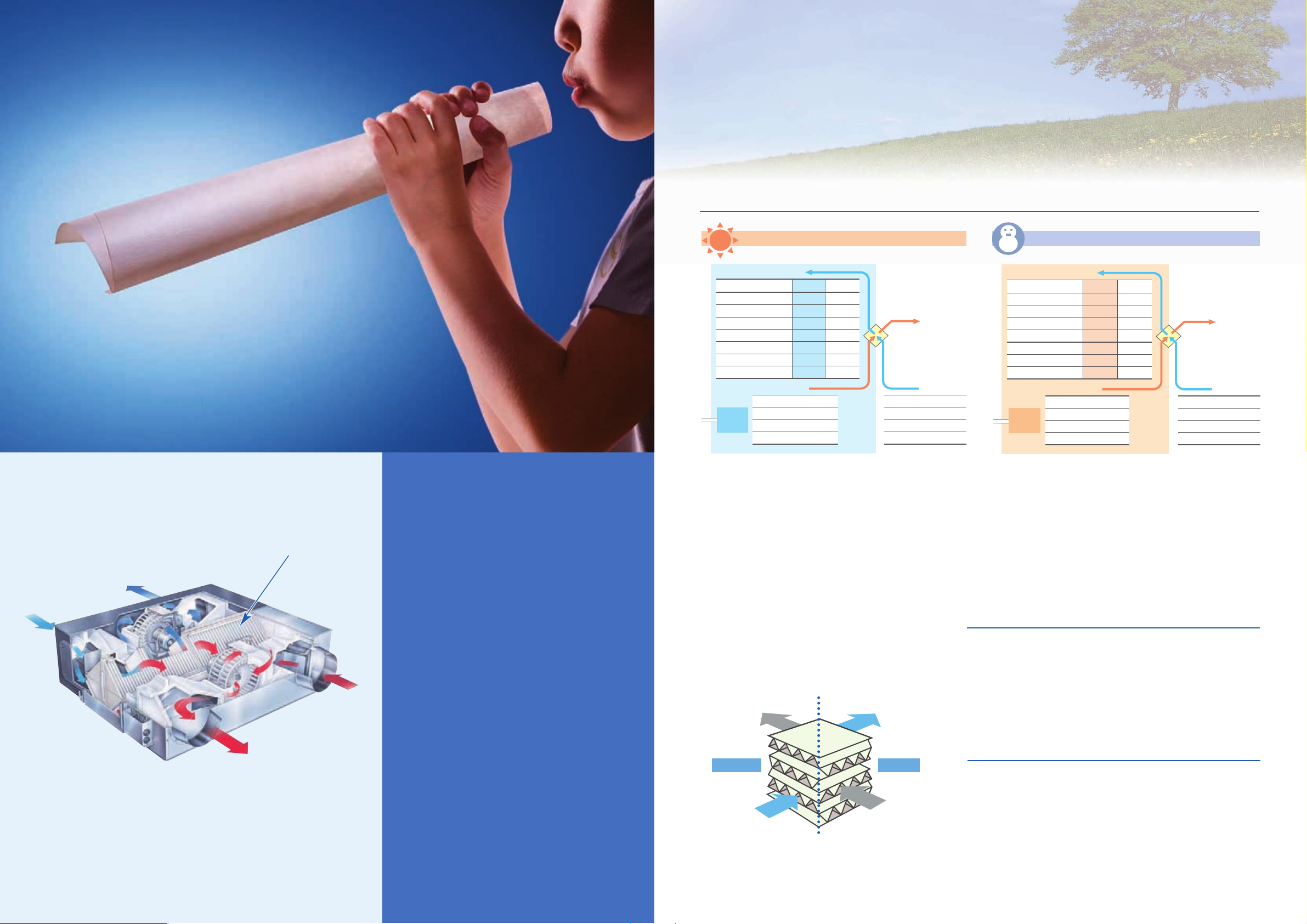
Try blowing into a rolled up piece of paper.
The warmth of your breath travels through
the paper to your hands.
Some 38 years ago, that simple principle led to the development
of our most advanced air-conditioning technology.
Fresh air
from outside
Fresh air supply
to the room
Stale room air
extracted
Stale exhaust
air
Heat exchange unit
(LOSSNAY core)
Simple and Effective
1 2
LOSSNAY's Energy Recovery Technology and
Simultaneous Ventilations (Supply and Exhaust)
Contribute to Excellent Indoor air Quality and
Significantly Reduce the Outdoor air load.
Temperature difference between air supply and room: 1.7 ºC
In summer
Supply air
Room air
Air
conditioner
Air
conditioner
About 4kg/h of water vapor is recovered.
In winter
Dry bulb temperature (ºC)
Absolute humidity (g/kg'(DA))
Relative humidity (%)
Enthalpy (kJ/kg(DA))
Total heat recovered (kW)
Outdoor air load (kW)
Outdoor air load ratio (%)
LOSSNAY
27.7
13.4
58
62.1
7.5
3.1
71
33
20.1
63
84.6
0
10.6
100
Conventional
ventilator
Dry bulb temperature
Absolute humidity
Relative humidity
Enthalpy
Dry bulb temperature
Absolute humidity
Relative humidity
Enthalpy
Outdoor air
Exhaust air
Supply air
Room air
Dry bulb temperature (ºC)
Absolute humidity (g/kg'(DA))
Relative humidity (%)
Enthalpy (kJ/kg(DA))
Total heat recovered (kW)
Outdoor air load (kW)
Outdoor air load ratio (%)
LOSSNAY
16
5.2
46
29.2
8.2
3.1
72.5
Conventional
ventilator
0
1.9
50
4.7
0
11.3
100
Dry bulb temperature
Absolute humidity
Relative humidity
Enthalpy
Outdoor air
Exhaust air
Dry bulb temperature
Absolute humidity
Relative humidity
Enthalpy
0ºC
1.9g/kg'(DA)
50%
4.7kJ/kg(DA)
20ºC
7.3g/kg'(DA)
50%
38.5kJ/kg(DA)
33ºC
20.1g/kg'(DA)
63%
84.6kJ/kg(DA)
26ºC
10.5g/kg'(DA)
50%
52.9kJ/kg(DA)
Energy-recovery calculating equation
Indoor supply-air
temperature (
º
C)
Indoor
temperature (
º
C)
Outdoor
temperature (
º
C)
_
}
×
Temp recovery
efficiency (%)
Outdoor
temperature (
º
C)
+
Calculation example : 16ºC=(20ºC_0ºC)×80%+0ºC
=
{
Energy-recovery calculating equation
Indoor supply-air
temperature (
º
C)
Outdoor
temperature (
º
C)
Indoor
temperature (ºC)
Outdoor
temperature (ºC)
_
_
{
}
×
Temp recovery
efficiency (%)
Calculation example : 27.7ºC=33ºC_(33ºC_26ºC)×76%
=
Every building needs a supply of fresh air to keep its inhabitants healthy and comfortable. Outdoor air though is rarely, if ever,
the same temperature as that maintained by the building,s air conditioning system. In the summer, it is too hot. In the winter, it
is too cold. This puts added stress on the air conditioner to compensate for the intake of the hot or cold air adding to the
expense of operating the system. LOSSNAY all but eliminates this problem with original energy-recovery technology that uses
the heat of the stale indoor air to be expelled in order to either heat or cool the incoming fresh air to a temperature much closer
to the existing indoor air. This process reduces the load on the air conditioning system without cutting off the supply of vitally
necessary fresh air.
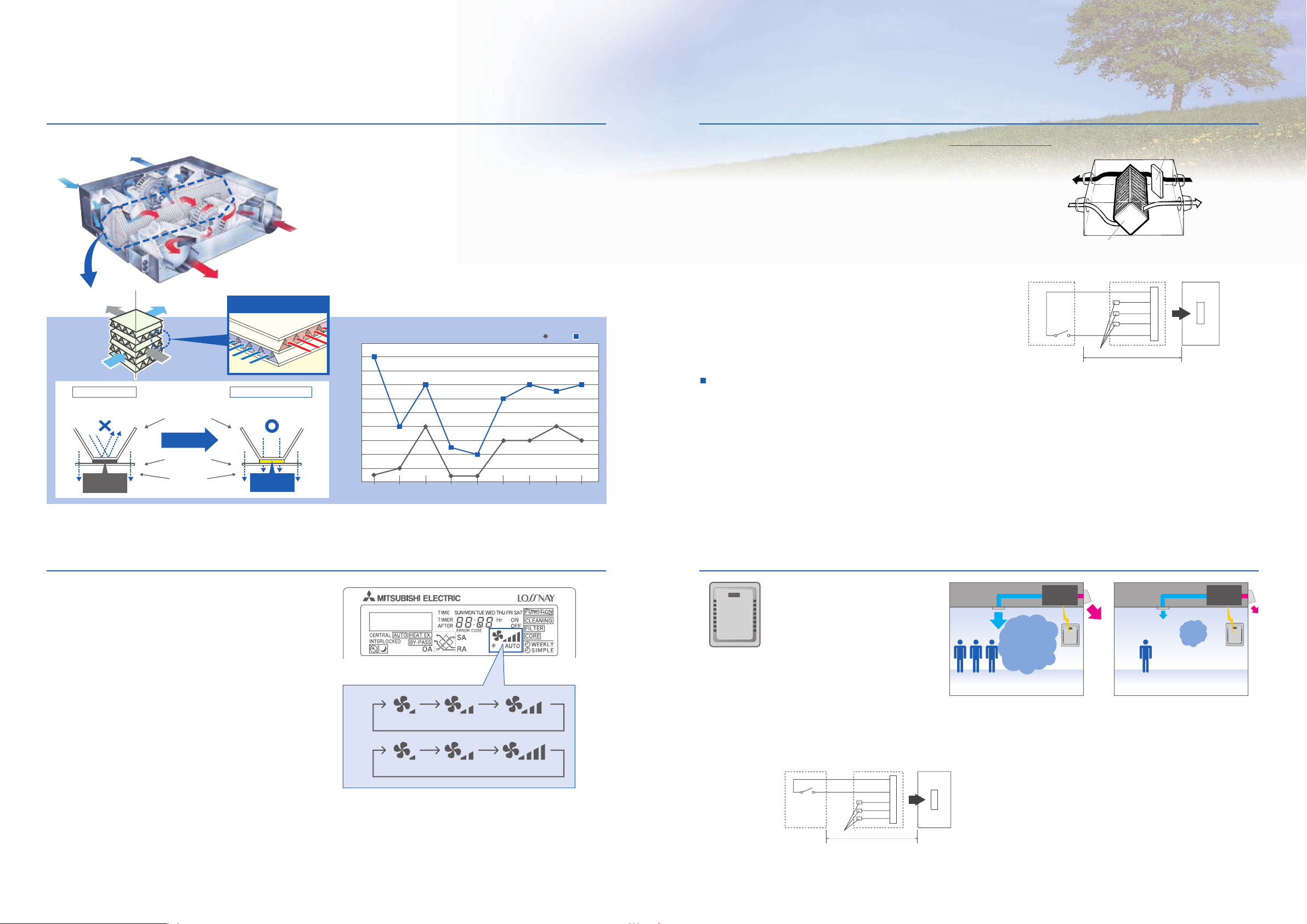
The remarkable technology that permits the intake of fresh air with
minimal loss to indoor temperature is know as the LOSSNAY
Core. The cross-flow, plate-fin structure of the energy-recovery
unit along with a specially processed diaphragm keep supply and
exhaust air separate, ensuring that only fresh air is introduced to
the indoor environment while also allowing for the efficient transfer
of heat.
The microscopically small pores of the diaphragm have been
made even smaller, decreasing the rate at which water soluble
gases such as ammonia and hydrogen pass through. Further, a
new specially processed paper used to make the diaphragm has
been developed with high moisture permeability characteristics
that aid in the transference of moisture for improved energy
exchange efficiency. These developments further improve
moisture permeability and effectiveness in shielding unwanted
gases, resulting in a lower rate of gas transference and more
highly efficient energy transfer.
LOSSNAY Core
Construction & Principle
Fresh air exhaust
(fresh heating/cooling air)
Stale air exhaust
(dirty indoor-air)
Stale air induction
(dirty heating/cooling air)
Fresh air induction
(fresh air)
SAEA
RAOA
* The above applies to the case of LGH-100RX5 (High notch).
Energy-Recovery Concept by Hyper Eco LOSSNAY Core
The improvements
The basic principle
Outdoors Indoors
Page 3
64%
65%
66%
67%
68%
69%
70%
71%
72%
73%
74%
15RX
Type
25RX
Type
35RX
Type
50RX
Type
65RX
Type
80RX
Type
100RX
Type
150RX
Type
200RX
Type
Enthalpy exchange efficiency improve
RX5RX5
*Cooling, High Fan speed, 50Hz
Spacerplates
Dividerplates
Humidity
Improved adhesive
agent material
RX4
Mitsubishi's newly developed Hyper Eco Element is on
board, offering the industry's best total heat exchange
efficiency. Energy conservation performance has been
improved not only by reducing the air conditioning load
associated with ventilation, but also by facilitating humidity
penetration.
Introducing the new Hyper Eco Element
Better energy conservation by improved total heat exchange efficiency.
In addition to the conventional Extra High, High, and Low
modes, an Extra Low mode is added to provide a more
dynamic range of air volume settings and versatility in a
variety of installation environments, yielding much better
energy conservation. Using a simplified timer function, it
switches to Extra Low operation when the operation stop
button is activated and it is accordingly possible to implement
24-hour energy conservation ventilation.
Additional energy conservation by using a
four-level air volume system that allows
more precise control.
Extra Low Mode
In addition to the automatic damper open/close
function, open/close control via external devices
is now possible, delivering a By-pass
ventilation system that is suitable to the installed
environment.
.
Temperature sensor
.
Humidity sensor
.
Timers
"By-pass" operation
New function: "By-pass" Ventilation External Control SettingHyper Eco Core
* When the outdoor air tempereture drops lower than 8
ºC it changes to the heat exchange
ventilation. (Display of the remote controller does not change)
* In the case of
“By-pass” ventilation, the supply air temperature slightly rises more than the
outside air temperature because of the heat effect around the ducts or the unit motors.
* The Extra High and High ventilation modes are selectable by the initial
setting.
* Extra-Low not equipped LGH-150RX
5 and 200RX5.
* The ventilation mode is actually selected in three levels, and the remote
controller also displays these three levels.
CO2 Sensor
CO2Sensor
High CO
2
density
Automatic ventilation setting
The automatic damper mode automatically provides the
correct ventilation for the conditions in the room. The
following shows the effect “By-pass” ventilation will have
under various conditions.
1. Reduces cooling load
If the air outside is cooler than the air inside the building
during the cooling season (such as early morning or
at night), “By-pass” ventilation will draw in the cooler
outside air and reduce the cooling load on the system.
2. Night purge
“By-pass” ventilation can be used to release hot air from
inside the building that has accumulated in buildings a
business district during the hot summer season.
3. Office equipment room cooling
During cold season, fresh air can be drawn in and used as
is to cool rooms where the temperature has risen due to
the use of office equipment.
SW1
CN16
CO2 sensor, etc.
(When CO2 increases: Closed)
SW1: High fan speed operation switch
(When closed: For High fan speed operation)
Remote display adaptor
(Optional) PAC-SA88HA-E
Brown 1
Red 2
Orange 3
Yellow 4
Green 5
Not used. Insulate completely.
Max wiring length 10 m
LOSSNAY
control board
Fan speed/
Ventilation
mode selection
When SW1 is "ON", fan speed of the LOSSNAY will be set
to "High"(Extra-High) regardless of the remote control setting.
Use this in such a way that it ventilates at Low or Extra-Low
fan speed normally, and when the external sensor detects
contamination of indoor air, it changes to High (Extra High)
fan speed operation.
To force High fan speed externally
Air volume can be set using a pin position.
CO2Sensor
Low CO
2
density
Establish the wire connection by inserting the optional remote
display adaptor (PAC-SA88HA-E) in the connector CN16
(Ventilation mode selector).
With SW1 is “ON”, the ventilation mode of LOSSNAY is
changed to the By-pass ventilation regardless of the
setting on the remote controller.
Hyper Element
Humidity does not
penetrate easily.
Adhesive agent
with low humidity
penetration rate
Humidity penetration is
facilitated.
New adhesive agent
with high humidity
penetration rate
Hyper Eco Element
Outdoors Indoors
EA
(exhaust air)
OA
(outside air)
RA
(return air)
OA
(outside air)
SA
(supply air)
RA
(return air)
Element Structure
Control devices (example)
SW1
CN16
SW1: By-pass ventilation operation switch
(When closed: For By-pass ventilation operation)
Remote display adaptor
(Optional) PAC-SA88HA-E
Brown 1
Red 2
Orange 3
Yellow 4
Green 5
Not used. Insulate completely
.
LOSSNAY
control board
Fan speed/
Ventilation
mode selection
Max wiring length 10 m
The system allows you to measure
CO
2 density and thereby control the
amount of fresh air supplied. By
connecting a CO
2 sensor to the
connector CN16, which is added to
the LOSSNAY main unit, the setting
can be switched to High, Low, or Extra Low
operation, which is selected when the sensor is
turned ON. This system produces additional energy
conservation.
Fan speed
High
Fan speed
Extra-Low
Damper
LOSSNAY core
Fresh air
Supply air
Exhaust air
Return air
Extra Low Low High
A)
Extra Low Low Extra High
B)
3 4
Page 4
5 6
Multi-ventilation Mode enables the appropriate supply/
exhaust balance to be selected to suit the usage environment and location
Featuring "Multi-ventilation Mode,"
which allows the air supply/exhaust
balance to be varied dynamically.
The supply/exhaust balance can be
selected to suit the usage environment
and location, such as allowing for air
exhausted via extractor fans. Modes can
be selected easily by setting the
connectors on the circuit board.
* "High notch" can also be further set to "Extra High" using the unit switch.
Offers choice of 9 air supply/exhaust combination patterns.
Hand-held remote control
for microprocessor type
Supply airflow
High
High
Low
Low
Exhaust airflow
High
Low
High
Low
Air supply and exhaust are "Low"
irrespective of unit setting.
Unit setting
* Factory setting is "High" for
both supply and exhaust.
Air supply
High
High
Low
Air exhaust
High
Low
High
Ventilation mode
Power air supply/exhaust mode
Power air supply mode
Power air exhaust mode
Energy-saving ventilation mode
Low
High
Control switch
Smaller offices or
tenant buildings, etc.
Using LOSSNAY compensates
for using extractor fans
...
Power air supply
Smoking areas, etc.
Priority on air exhaust
...
Power air exhaust
Normal office, etc.
Providing efficient ventilation
while maintaining air
supply/exhaust balance
...
Power air supply
/exhaust
Energy Saving by
Energy Saving by
Night Purge Function
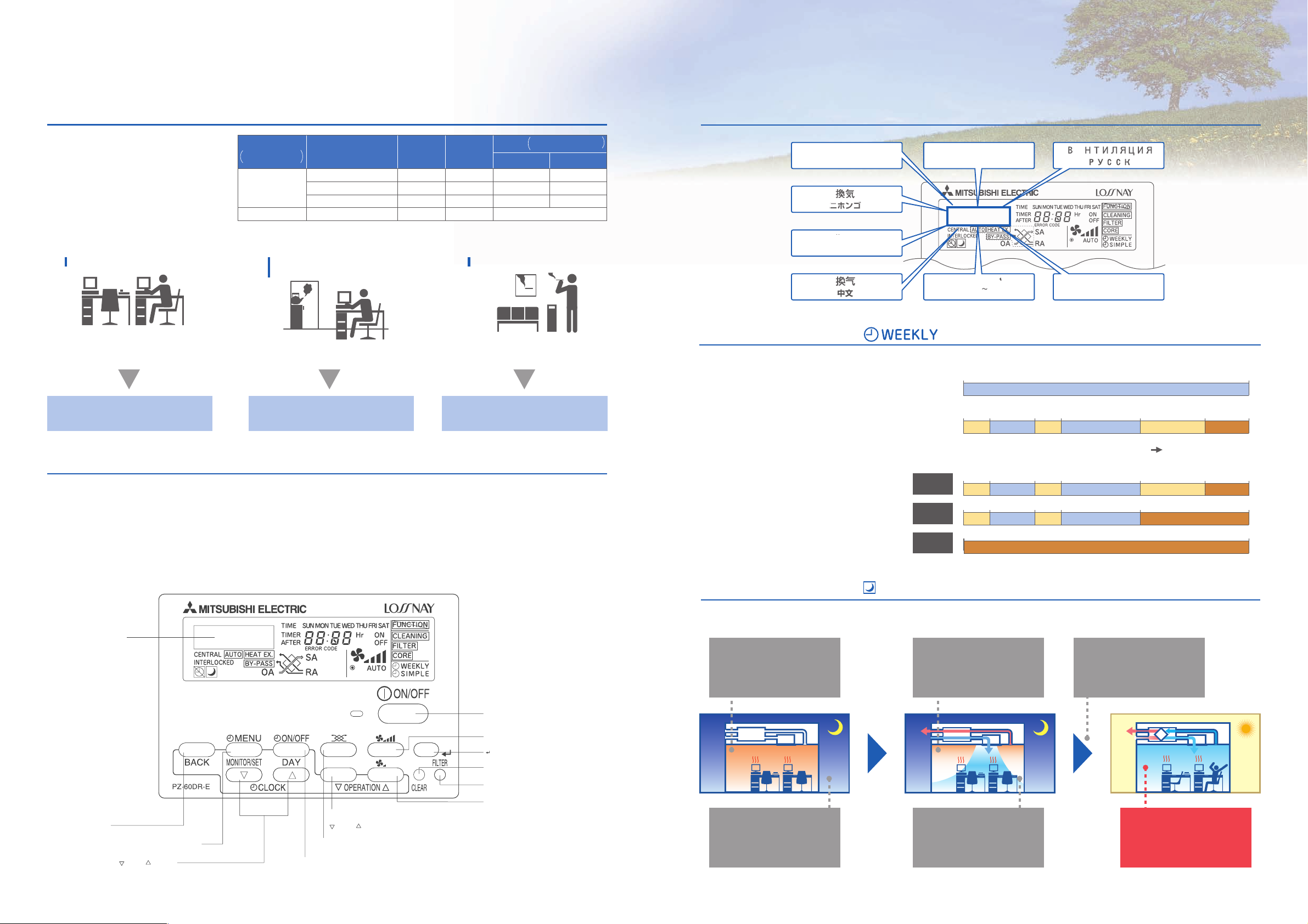
Newly Adopted Dot Matrix Display Available in Eight Languages
During the summer season, the Night Purge function draws cooler outside air into the room to suppress temperature
rises at night. This energy conservation function reduces the load when air conditioning is started the next morning.
timer
The out door temperture (OA) setting can be selected either 17゜ C or 28゜ C by using Dip-Switch (SW2-7) in the LOSSNAY control box. Refer to the Instillation Manual for more information.
*Do not use the night purge function if fog and heavy rain is expected. The entry of rain water may occur in the night.
While air conditioning and
ventilation are not operating,
the room temperature rises as
a result of heat from the
skeleton and OA equipment.
When the outside temperature
becomes lower than the room
temperature, ventilation starts
automatically.
The air conditioning load
required to reach the set
temperature the next
morning is reduced.
At night, the outside
temperature drops.
When the room becomes
sufficiently cool, ventilation
is stopped.
Hot air is discharged.
Example B (Weekly)
Example A (Hourly)
8:00 9:00 12:00 13:00 17:00 19:00 22:00
low high low high low extra low
new RX5 series with PZ-60DR-E
8:00
high
current RX4 series with PZ-41SLB controller
22:00
New Remote Controller PZ-60DR-E
A new remote controller for the RX5 series is now available. In addition to boosting the energy conservation performance of
the main unit, the remote controller features a variety of new functions which also pursue additional energy conservation.
The appearance of the remote controller conforms to Mitsubishi air conditioner interface design standards.
Functions that were set using Dip-Switch on the LOSSNAY main unit can now be configured as needed using the new remote controller. This eliminates the need to crawl under the eaves to change operation settings.
Also, a newly adopted dot matrix display provides much more information, making it easy to check maintenance indications, operation status display, and explanations required when configuring settings.
Tolal power consumption in one day : LGH-100RX4-E : 6,600W (14 hours)
LGH-100RX
5-E : 5,390W (14 hours)
1,210W (18%) less
8:00 9:00 12:00 13:00 17:00 19:00 22:00
low high low high low extra low
Monday
to
Thursday
8:00 9:00 12:00 13:00 17:00 22:00
low high low high extra low
Friday
extra low
8:00 22:00
Saturday
to
Sunday
VENTILATION
ENGLISH
Geblasebetrieb
Deutsch
VENTILATION
FRENCHESPANOL
ARIAESTERNA
ITALIANO
Air volume level can be set hourly (max 8
times) and weekly. You can pre-set air
volume according to the predictable
requirement so that LOSSNAY can
automatically operate at only necessary
air-speed at the specified time period,
which saves power consumption while
maintaining the indoor air quality.
Besides, once the weekly timer has been
set, no switching on-off is required.
Dot matrix display
Button
Filter button
"Extra Low" fan speed button
OPERATION button
ON/OFF button
Function selector button
Set time buttons
Back Ahead
OPERATION buttons
Back Ahead
Fan speed Adjustment button
CLEAR button
Timer ON/OFF (DAY) button
Timer MENU (MONITOR/SET) button
Return button
VENTILACIoN
e
Page 5
7 8
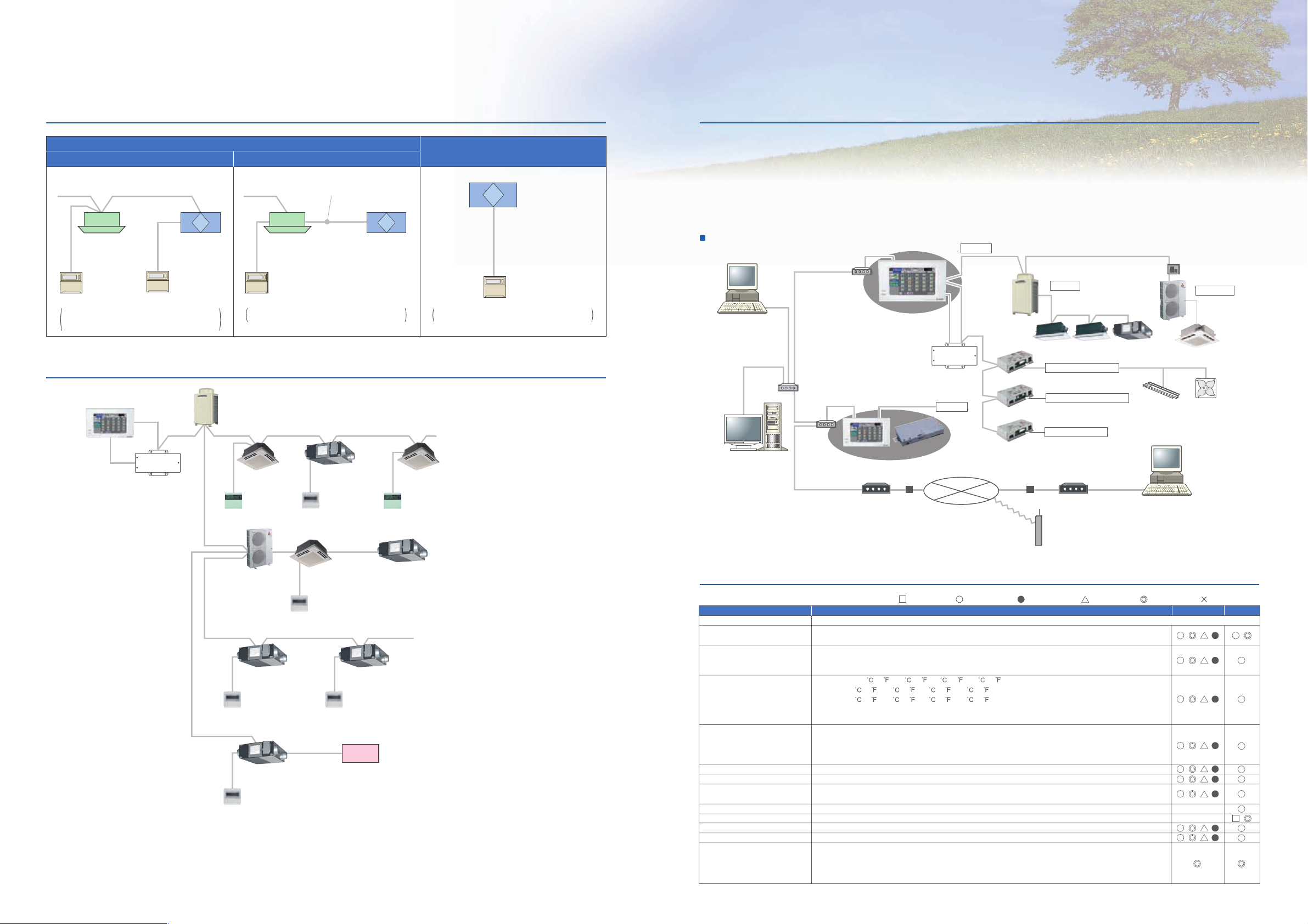
The New Remote Controller PZ-60DR-E enable simple control setting
Can Be Used With AG-150A Centralized Controller
Centralized Controller System
LOSSNAY independent
Interlocked with Air conditioners
Interlocked with City Multi Interlocked with Mr.Slim
City Multi
M-NET transmission line
Mr.Slim LOSSNAY
RX
5
LOSSNAY
RX
5
Slim-LOSSNAY connection cable
LOSSNAY remote
controller
PZ-60DR-E
LOSSNAY remote
controller
PZ-60DR-E
can be connected
LOSSNAY RX
5
(Max 15 unit)
PZ-52SF-E can be used insted of PZ-60DR-E,
However, function is limited and connecting
position is different.
The LOSSNAY remote controller (PZ-60DR-E,
PZ-41SLB-E) can not be used with this system.
PZ-41SLB-E can be connected however function
is limited.
Centralized controller
AG-150A
Power supply unit
(PAC-SC51KUA)
Outdoor unit
Network remote
controller
Mr.Slim
remote controller
LOSSNAY remote
controller
PZ-60DR-E
LOSSNAY remote
controller
PZ-60DR-E
Mr.Slim
outdoor unit
Mr.Slim
indoor unit
Network remote
controller
LOSSNAY
RX
5
LOSSNAY
RX
5
LOSSNAY
RX
5LOSSNAY RX5
LOSSNAY remote
controller
PZ-60DR-E
LOSSNAY
RX
5
Ext. signal source
LOSSNAY remote
controller
PZ-60DR-E
Interlocked with
City Multi indoor units
Interlocked with
Mr. Slim indoor units
LOSSNAY units only
Interlocked with
external devices
Internet
Switching Hub
Hub
LAN
(100BASE-TX)
A Control
Central Control PC
(TG-2000A)
*Ver. 5.50 or later
Remote
Monitoring PC
Hub
DIDO Controller (PAC-YG66DCA)
General Equipment
Temp/Humidity sensor
Watt hour meter
AI Controller (PAC-YG63MCA)
PI Controller (PAC-YG60MCA)
Note : Use a security device such as a VPN router when connecting the
AG-150A to the Internet to prevent unauthorized access.
AG-150A / GB-50A
M-NET
M-NET
Service company
/Sales office
Mobile phone
of service person
Remote
monitoring PC
M-NET
M-NET
adapter
AG -
150
A
Remote monitoring
via a Web browser
Remote monitoring
via a Web browser
VPN
Router
VPN
Router
Modem
Power supply unit
(PAC-SC51KUA)
Lights Ventilation
Modem
Functions
Item
Controllable unit
ON/OFF
Operation mode switching
Temperature setting
Fan speed setting
Air flow direction setting
Schedule operation
Permit / Prohibit
local operation
Indoor unit intake temperature
Error
Test run
Ventilation interlock
External input/output
Description
Up to 50 units/groups.
Run and stop operation for the air conditioner units and general equipment.
(To operate general equipment, PAC-YG66DCA is required.)
Switches between Cool / Dry / Auto / Fan / Heat. (Group of LOSSNAY unit : automatic ventilation/
vent - heat interchange/ normal ventilation) depending on the air conditioner unit.
Auto mode is for City Multi R2 and WR2 series only.
Cool/Dry : 19
(67 ) - 30 (87 ) [14 (57 ) - 30 (87 )]
Heat : 17 (63 ) - 28 (83 ) [17 (63 ) - 28 (83 )]
Auto : 19 (67 ) - 28 (83 ) [17 (63 ) - 28 (83 )]
[ ] in case of using middle-temperature on PDFY, PEFY-VML/VMR/VMS/VMH-by setting DipSW7-1 to ON.
Yet, PEFY-P-VMH-E-F is excluded.
Models with 4 air flow speed settings: Hi/Mid-2/Mid-1/Low
Models with 3 air flow speed settings: Hi/Mid/Low
Models with 2 air flow speed settings: Hi/Low
Fan speed setting (including Auto) varies depending on the model.
Air flow direction angles, 4-angle or 5-angle Swing, Auto (Louver cannot be set)
Weekly schedule can be set by groups based on daily operation pattern.
Individually prohibit operation of each local remote control function
(Start/Stop, Change operation mode, Set temperature, Reset filter).
Measures the intake temperature of the indoor unit only when the indoor unit is operating.
When an error is currently occurring on an air conditioner unit, the afflicted unit and the error code are displayed.
This operates air conditioner units in test run mode.
The ventilation unit (LOSSNAY) is able to automatically start its operation when operation of the interlocked indoor unit starts.
By using optional external input/output adaptor (PAC-YG10HA) you can set and monitor the following.
Input : By level signal : "Batch start/stop", "Batch emergency stop"
By pulse signal : "Batch start/stop", "Enable/disable local remote controller"
Output : "Start/stop", "Error/Normal"
Operations
Display
X
X
*NOTE: Operation and displayed content vary depending on the indoor unit model.
:
Each block
System structure
Controllers are one of the most important and familiar devices in an air conditioning system. Not only does it control to provide
optimum air environment but supports operations to minimize running costs and to preserve energy. Through studies and
development, we've visualized a new system controller meeting needs with versatile options.
With a new coloured touch panel, new functions, and continuation of all the current G-50A functions, AG-150A visualizes its
functions from basic control to advanced operations and bringing an ultimate controller to reality.
– Design your control
with our new centralized controller; AG-150A.
Indoor unit Indoor unit
:
Each floor
:
Each unit
:
Collective
:
Each group
:
Not available
Control
Page 6

Standard installation
9 10
List of Remote Controller Settings and Functions
The remote controller provides a wide range of functions and features other than the main functions described above, such as
sophisticated energy conservation control and an easy to see, easy to use interface.
Connect ducts in two different directions (OA, EA side)
Installation with duct direction changed
A space is necessary to
prevent the influx of
rainwater.
Collar
Aperture Plate
Exchangeable
Can be installed
close to the surface
of the wall.
Avoid installations
where the stale air
exhaust aperture
would be blocked by
lighting or air conditioning units.
Remove the collar (factory-standard direction) and the side
panel aperture plate and switch their placements. They are
both equipped with screw stoppers making the switch extremely simple.
The direction of the ducts can only be changed on the outside
(OA and EA).
The inside cannot be changed (SA and RA).
Changing the duct direction
Ducts can be connected in two different directions to the outdoor vents thanks to collars and aperture plates that can be interchangeably placed in two different positions. This flexibility allows for installations close to the surface of a wall and helps
avoid cases where the stale air exhaust vent would be blocked by an obstruction of some kind. This makes both planning and
installation that much simpler.
The position of the suspension bracket is changed to improve workability.
OA/EA square duct (LGH-150・200R)
OA/EA is square duct. This simplifies
installation and reduces total installation
time.
By attaching the suspension
bracket in the center of the product,
the suspension bracket does not
need to be moved even when the
product is mounted upside down.
(Model LGH-15 to 65)
Incorporation into the main unit is simple, and filter changes can be performed via the main unit inspection opening.
FLOW
取 付 日
年 月 日
AIR
C
B
A
EA OA
Lighting, etc.
B
C
A
Controllers
New Controller
Function(Communicating mode)
New Function
Extra low fan speed (Except LGH-150RX
Weekly timer
Simple timer
Night Purge mode
Multi languages display
24-hours ventilation (Except LGH-150RX5 and 200RX5)
Operation function limit
Clock display
Contact number setting for error situation
LOSSNAY core cleaning sign
Air volume display by external signal
By-pass display by external signal
Possible setting from the controller in addition to unit Dip-SW setting
Extra High / High switch setting
Multi Ventilation mode
Power supply / exhaust when operation starts
Pulse input
Inter locking mode
Automatic recovery following power supply interruption
Delay operation at heating or cooling start-up
Operation output monitor
Exhaust fan stop at outdoor air lower than -15ºC
Exhaust fan stop during defrosting,exhaust fan Low speed operation at outdoor air lower than -15ºC
By-pass automatic ventilation priority setting
Filter cleaning sign
Maintenance display
Total operated hours
Total LOSSNAY mode operated hours
Error history
Carry on function
In the use of MELANS M-NET
2 controllers display
"Central" indication(use prohibition)
5 and 200RX5)
PZ-60DR-E
(V Controlling)
PZ-41SLB-E
(V Controlling)
(in unit setting)
(in unit setting)
(in unit setting)
(in unit setting)
only auto recover mode
(in unit setting)
(in unit setting)
(in unit setting)
(in unit setting)
PZ-52SF-E
(M-NET)
(in unit setting)
(in unit setting)
(in unit setting)
(in unit setting)
(in unit setting)
(in unit setting)
(in unit setting)
(in unit setting)
(in unit setting)
(in unit setting)
(in unit setting)
(in unit setting)
LOSSNAY remote controller (PZ-60DR-E
LOSSNAY remote controller (PZ-41SLB-E
*Stock available only.
Source power requirement
Interface condition for
transmission line
Number of LOSSNAY units
controlled by PZ-41SLB-E
Input voltage:
Specialized transmission line:
DC power+AM modulation
1–15
)
120
130
19
Unit: mm
)
120
8
70
48
9VDC-15VDC, 0.02A
Power received from a LOSSNAY
unit, TM4 1 - 2
33
Unit: mm
Source power requirement
Number of LOSSNAY units
controlled by PZ-41SLB-E
LOSSNAY
*Stock available only.
Source power requirement
Interface condition for
transmission line
Number of M-NET controlled LOSSNAY
units controlled by PZ-52SF-E
M-NET remote controller (PZ-52SF-E
Filters
Standard filter High-efficiency filter
Replacement components for the standard air filter supplied with the
LOSSNAY LGH main unit.
This high-efficiency filter (with 65% colorimetricity EU-F7) can be incorporated inside the LOSSNAY unit without the need to attach parts from other
systems, as done to date. The main unit external dimensions are unchanged,
and processing capacity ranges between 150m
Power received from a LOSSNAY unit,
TM4 1 - 2
1–15
)
120
8
70
48
Input voltage:
M-NET transmission line:
30VDC+AMI signal (±5VDC)
1–16
17VDC–30VDC, 0.02A
Power received from an outdoor
unit or a power supply unit via
M-NET transmission line.
3
/h and 2,000m3/h.
33
Unit: mm
EA OA
EA OA
Dimension (mm)
Model Applicable model
PZ-25RF
PZ-35RF
PZ-50RF
PZ-65RF
PZ-80RF
PZ-100RF
ABC
8-E
333
8-E
399
8-E
470
8-E
433
8-E
451
8-E
565
156
183
183
218
243
243
filters per set
Supply
15
20
15
15
15
15
Number of
Exhaust
2
2
2
2
2
2
2
2
2
2
2
2
LGH-15RX5-E,LGH-25RX5-E
LGH-35RX
LGH-50RX
LGH-65RX
LGH-80RX5-E,LGH-150RX5-E(2sets)
LGH-100RX
5
-E,LGH-200RX5-E(2sets)
144
171
171
205
232
232
Number of
filters
per set
2
2
2
2
2
2
LGH-15RX5-E,LGH-25RX5-E
LGH-35RX
5
-E
LGH-50RX
5
-E
LGH-65RX
5
LGH-80RX5-E,LGH-150RX5-E(2sets)
LGH-100RX
-E
5
-E,LGH-200RX5-E(2sets)
Filter
material
Non combustible
fiber
(Polyester
polyolefin)
(EU-F7)
Filter
material
PZ-25RFM
5
-E
-E
-E
Nonwoven filter
Collection
efficiency
(EU-G3)
5
5
PZ-35RFM
PZ-50RFM
PZ-65RFM
PZ-80RFM
PZ-100RFM
Dimension (mm)
Model Applicable model
AB
327
393
464
427
446
559
Page 7

11 12
A Breath of Freshness in Restaurants, Offices, and Schools
Restaurants Offices Schools
A restaurant can never be too clean and
its air never too fresh
The atmosphere of a restaurant is crucial to securing
customers and making them happy enough to come back
for more. Cleanliness is the key to an attractive atmosphere and restaurants devote significant effort to ensuring
the premises are sanitary. Sanitation and cleanliness, however, are not enough. No matter how clean a restaurant
may look, if there are bothersome odors lingering in the air,
all those efforts go to waste and the restaurant's clean
image is tarnished. For these reasons, we invite restaurant
owners to leave the air to LOSSNAY. LOSSNAY's superior
ventilation capabilities ensure that every breath is a breath
of freshness keeping guests happy. LOSSNAY also keeps
owners happy with its remarkable heat recovery technology
that supplies fresh outdoor air with minimal change to
indoor temperature, saving on energy and expense.
If it’s LOSSNAY...
Ventilators work to exhaust stale air and supply fresh,
clean air free of the odors associated with cooking,
cigarettes, and the people working and dining.
Fresh air–improving the overall quality
of working life
Many office buildings today are heavily insulated air-tight
structures with little or no natural ventilation. The unnatural
environment created by air conditioners without added ventilation is a breeding ground for bacteria. Factor this in with
the accumulation of pollutants and odors in the form of
cigarette smoke, formaldehyde, pollen, dust, and carbon
dioxide, and the necessity of ventilation becomes ever more
apparent. In fact, poorly ventilated buildings can give rise
to Sick Building Syndrome, a malady that is known to cause
headaches, sore eyes, itching, and concentration loss.
This results not only in discomfort at best and sickness at
worst for the building's occupants, but also the reduced
productivity of the workforce. Fresh air, effectively ventilated throughout the building, is therefore essential to the
overall quality of working life.
If it’s LOSSNAY... If it’s LOSSNAY...
Simultaneous forced-air supply and exhaust introduces
fresh, outdoor air into the building,
effectively ventilating even fully airtight structures.
Creating the best possible environment
for our children to succeed
Children deserve all the help we can give for them to grow
up healthy, happy, and prosperous. No matter how good a
school's curriculum, no matter how positive and enthusiastic
the teacher, a child who does not feel well will have a hard
time learning. The constant flow of fresh air is nowhere as
important as it is in our schools. In classrooms where large
numbers of students are gathered for long periods of time,
carbonic gases have the tendency to accumulate, decreasing the levels of oxygen that are vital for alertness and concentration. This is especially true during the winter months
when windows tend to remain closed. LOSSNAY ventilates
fresh outdoor air into classrooms to replenish the supply of
oxygen and expels not only carbon dioxide, but also other
pollutants and odors that inevitably sully the air.
The continuous influx of fresh, outdoor air and the exhaust
of stale, indoor air ensure that the indoor oxygen level is
maintained at just the right balance for comfort and health.
Change in room temperature is kept to a minimum during
ventilation thanks to the heat-recovery function.
The ventilators operate very quietly so those in
the midst of enjoying their meals will not be bothered
by any excess noise.
A large array of ventilators is available to match
the layout of just about any restaurant.
What would you most like to see improved in restaurants?
52.3%
Improvement in overall cleanliness
1996 Foodstuffs Consumption Monitor, Second Periodic Survey (Ministry of Agriculture, Forestry and Fisheries, Japan)
Others: No response
Promotion of waste prevention: 5.4%
Improvement in atmosphere: 6.5%
Reduction of time required for
food to reach the table: 12.0%
Improvement in employees’
attitude toward customer
service: 20.5%
Multiple split-type units operate independently of
one another, simplifying system set up and ensuring a
layout that optimally matches nearly any office design.
LOSSNAY operation can be interlocked with
air-conditioning system operation.
Heat that is commonly lost due to ventilation is collected
and reused thanks to the LOSSNAY Core,
reducing air conditioners’ energy load and
cutting operating costs.
Occupants have the luxury of breathing fresh air at
all times even in highly air-tight buildings.
LOSSNAY's sound attenuation qualities prevent outside
noise from penetrating into the room, helping to
maintain a quiet environment for productive study.
Heat-exchange technology prevents fluctuations
in temperature for significant energy savings
when either heating or cooling a room.
O2 concentration and deficiency
21
Normal air
15
10
5
O2 Concentration (%)
0
21%
18%
Safety
minimum
16%
Increased
respiration
and pulse
12%
Dizziness,
nausea,loss of
muscle strength
(precursors
to death)
10%
Paleness of
skin, vomiting.
Unconsciousness
8%
Comatose
(death in 8min)
6%
Convulsions
respiration
stops, death
Page 8

Specifications / Dimensions
LGH-15 to 100RX5
LGH-15RX5-E
Model
Frequency / Power source
Ventilation mode
Fan speed
Current (A)
Power consumption (W)
Air volume
External static pressure
Temperature exchange efficiency (%
Enthalpy exchange efficiency (%
(Measured at 1.5m under the center
)
Noise (dB
Weight (kg
Starting current
*The Air outlets noise (45 angle,1.5meters in front of the unit) is about 6dB greater than the indicated value.(at High Fan speed)
of panel in an anechoeic chamber)
)
90
Exchange
efficiency
(%)
80
70
60
300
30
250
25
(m
(L/s
(mmH
(Pa
)
Heating
)
Cooling
Enthalpy exchange
Enthalpy exchange
Extra High High Low Extra Low
0.44-0.46
96-110
3
)
/h
150
)
2O
)
)
42
10.2-10.7
100-105
82.0
75.0
73.0
27.5-28
50Hz/Single phase 220V
Temperature exchange
efficiency
efficiency(Heating)
efficiency(Cooling)
LOSSNAY ventilation By-pass ventilation
0.37-0.38
80-90
150
42
6.6-7.1
65-70
82.0
75.0
73.0
26.5-27
100mm
dia
pipe
length
20m
0.25-0.25
53-59
110
31
3.6-4.1
35-40
84.0
77.5
76.5
22-23.5
LGH-15RX
50Hz / Single phase 220-240V
0.14-0.15
30-35
70
19
1.4
14
85.5
81.0
81.0
18
20
Under 0.8A Less
90
Exchange
efficiency
(%)
80
70
60
300
30
250
25
5-E
Extra High High Low Extra Low
0.45-0.46
97-110
150
42
10.2-10.7
100-105
28.5-29
0.37-0.38
81-91
150
42
6.6-7.1
65-70
27-28
0.25-0.26
54-61
110
31
3.6-4.1
35-40
23-24
0.14-0.15
30-35
70
19
1.4
14
18-19
50Hz/Single phase 240V
Temperature exchange
Enthalpy exchange
Enthalpy exchange
efficiency
efficiency(Heating)
efficiency(Cooling)
100mm
dia
pipe
length
20m
LGH-150 and 200RX5
50
External static pressure
200
20
150
15
aP
100
10
2
Hmm O
5
0
Extra low
50
050100 150 200 250
070605040302010
Extra high
Low
High
(m2/h)
Air volume (L/s)
(exhaust air outlet)
(outside air intake)
Core, air filter, HighEfficiency filter, fan,
Maintenance space
Air exhaust fan
EA
530
735
OA
More than 600
LOSSNAY core
103
30
150~250
102
102
15m
10m
5m
50
External static pressure
Position where duct direction change is possible
By-pass damper plate
768
Inspection
opening
780
Ceiling suspension fixture
(4-13x20 oval)
(supply air)
20 782
Air supply fan
Control box
Maintenance cover
High efficiency filter(sold separately)
attachment position
103
97.5
20
15
OmmH
10
2
5
0
RA
(return air)
SA
Power supply
cable opening
110
Pa
200
150
100
50
Extra low
10 20 30 40 50 60 700
65
65
Extra high
Low
273
High
(m2/h)
Air volume (L/s)
95
30
15m
10m
5m
250200150100500
Position where duct direction
change is possible
Air filters(EU-G3)
Unit: mm
13 14
Page 9

15 16
/s)
Unit: mm
)
)
Unit: mm
LGH-25RX5-E LGH-35RX5-E
5-E
Model
Frequency / Power source
Ventilation mode
Fan speed
Current (A)
Power consumption (W)
Air volume
External static pressure
Temperature exchange efficiency (%
Enthalpy exchange efficiency (%
(Measured at 1.5m under the center
)
Noise (dB
Weight (kg
Starting current
*The Air outlets noise (45 angle,1.5meters in front of the unit) is about 10dB greater than the indicated value.(at High Fan speed)
of panel in an anechoeic chamber)
)
)
(m
(L/s
(mmH
(Pa
)
Heating
Cooling
Extra High High Low Extra Low
0.52-0.55
113-129
3
)
/h
250
)
2O
)
69
)
8.2-8.7
80-85
79.0
69.5
68.0
26-27
LOSSNAY ventilation By-pass ventilation
0.47-0.48
102-114
250
69
5.1-6.1
50-60
79.0
69.5
68.0
25-26
0.26-0.27
56-62
155
43
2-2.5
20-25
81.5
74.0
72.5
20-21.5
LGH-25RX
50Hz / Single phase 220-240V
Extra High High Low Extra Low
0.17-0.18
36-42
105
29
0.9
9
83.5
77.5
76.0
18-19
Under 0.9A Less
0.53-0.55
115-131
250
69
8.2-8.7
80-85
26.5-27.5
20
0.47-0.48
103-115
250
69
5.1-6.1
50-60
25.5-26.5
0.26-0.27
56-63
155
43
2-2.5
20-25
20.5-22
0.17-0.18
36-42
105
29
0.9
9
18-19
Model
Frequency / Power source
Ventilation mode
Fan speed
Current (A)
Power consumption (W)
Air volume
External static pressure
Temperature exchange efficiency (%
Enthalpy exchange efficiency (%
(Measured at 1.5m under the center
)
Noise (dB
Weight (kg
Starting current
*The Air outlets noise (45 angle,1.5meters in front of the unit) is about 10dB greater than the indicated value.(at High Fan speed)
of panel in an anechoeic chamber)
)
)
3
/h
(m
)
(L/s
2O
(mmH
)
(Pa
)
Heating
Cooling
Extra High High Low Extra Low
0.92-0.92
195-212
)
350
97
)
15.8-16.3
155-160
80.0
71.5
71.0
32-32
LOSSNAY ventilation By-pass ventilation
0.74-0.74
160-169
350
97
7.6-8.2
75-80
80.0
71.5
71.0
28.5-29.5
0.5-0.51
105-116
210
58
2.5-3.1
25-30
85.0
76.5
75.5
21.5-23
5-E
LGH-35RX
50Hz / Single phase 220-240V
Extra High High Low Extra Low
0.28-0.3
58-69
115
32
0.9
9
88.0
81.5
81.0
18
Under 2.4A Less
0.93-0.94
197-217
350
97
15.8-16.3
155-160
32.5-32.5
29
0.77-0.77
164-173
350
97
7.6-8.2
75-80
29.5-30.5
0.51-0.52
105-116
210
58
2.5-3.1
25-30
21.5-24
0.28-0.3
58-69
115
32
0.9
9
18
90
Exchange
efficiency
80
70
60
50
250
25
200
20
150
15
O
2
100
10
Hmm
Pa
50
5
External static pressure
0
0
Enthalpy exchange
Enthalpy exchange
Extra high
Low
High
Extra low
3020100
Air volume (L/s
50Hz/Single phase 220V
Temperature exchange
efficiency
efficiency(Heating)
efficiency(Cooling)
(m2/h)
Air exhaust fan
(exhaust air outlet)
(outside air intake)
Core, air filter, HighEfficiency filter, fan,
Maintenance space
Position where duct direction
change is possible
EA
735
OA
More than 600
LOSSNAY core
150
dia
pipe
length
40m
30m
20m
10m
40050 100 150 200 250 300 350
1009080706040 50
Position where duct direction change is possible
102
768
530
102
Inspection
opening
150~250
63 63
30
780
Air filters (EU-G3)
90
Exchange
efficiency
80
70
60
50
By-pass damper plate
Ceiling suspension fixture
(4-13x20 oval)
RA
(return air)
78220
SA
(supply air)
Air supply fan
Control box
Maintenance cover
High efficiency filter(sold separately)
attachment position
160
142
250
25
200
20
150
15
O
2
100
10
Hmm
Pa
50
5
External static pressure
0
0
Power supply
cable opening
0
Extra high
10
65
65
Enthalpy exchange
Low
273
50Hz/Single phase 240V
Enthalpy exchange
High
Extra low
(m2/h)
Air volume (L/s
95
30
Temperature exchange
efficiency
efficiency(Heating)
efficiency(Cooling)
1009080706040 50
150
dia
pipe
length
40m
30m
20m
10m
40050 10030150 200 250 30020350
90
Exchange
efficiency
(%)
80
70
60
50
2
m
External static pressure
350
300
30
250
25
200
20
150
15
100
10
HOm
Pa
50
5
0
0
Enthalpy exchange
Enthalpy exchange
Extra high
Extra
low
50 100 150 500450400350300250200
Air volume (L/s)
50Hz/Single phase 220V
Temperature exchange
efficiency
efficiency(Heating)
efficiency(Cooling)
High
Low
(m2/h)
120100806040200
Air exhaust fan
(exhaust air outlet)
(outside air intake)
Core, air filter, HighEfficiency filter, fan,
Maintenance space
Position where duct direction
change is possible
EA
874
OA
More than 600
LOSSNAY core
140
650
150~250
55
150mm
pipe
length
30m
20m
10m
124
124
90
Exchange
efficiency
(%)
80
70
60
dia
Position where duct direction change is possible
875
Inspection
opening
888 6464
Air filters(EU-G3)
30
50
25
20
15
10
2
Pa
m
mOH
5
External static pressure
0
By-pass damper plate
Ceiling suspension fixture
(4-13x20 oval)
RA
(return air)
92120
SA
(supply air)
Power supply
cable opening
Air supply fan
Control box
Maintenance cover
High efficiency filter(sold separately)
attachment position
160
142
350
300
250
200
150
100
50Hz/Single phase 240V
Temperature exchange
200 250 300 350 400 450 50015010050
Low
(m2/h)
95
efficiency
efficiency(Heating)
efficiency(Cooling)
High
150mm
dia
pipe
length
30m
20m
10m
Enthalpy exchange
Enthalpy exchange
Extra high
Extra low
50
0
40200 1201008060 140
Air volume (L
80
80
55
315
Page 10

17 18
Unit: mm
Unit: mm
LGH-50RX5-E LGH-65RX5-E
5-E
Model
Frequency / Power source
Ventilation mode
Fan speed
Current (A)
Power consumption (W)
Air volume
External static pressure
Temperature exchange efficiency (%
Enthalpy exchange efficiency (%
(Measured at 1.5m under the center
)
Noise (dB
Weight (kg
Starting current
*The Air outlets noise (45 angle,1.5meters in front of the unit) is about 16dB greater than the indicated value.(at High Fan speed)
of panel in an anechoeic chamber)
)
(mmH
Heating
)
Cooling
(m
(L/s
(Pa
)
Extra High High Low Extra Low
1.2-1.25
255-286
3
)
/h
500
)
139
)
15.3-15.8
2O
)
150-155
78.0
69.0
66.5
33-34
LOSSNAY ventilation By-pass ventilation
1.0-1.0
207-228
500
139
6.6-9.2
65-90
78.0
69.0
66.5
30.5-32
0.85-0.85
175-190
390
108
4.1-6.1
40-60
81.0
71.0
68.0
26.5-28
LGH-50RX
50Hz / Single phase 220-240V
Extra High High Low Extra Low
0.4-0.4
80-95
180
50
1.0
10
86.0
78.0
77.0
19
Under 3.0A Less
1.25-1.25
260-290
500
139
15.3-15.8
150-155
34-35
32
1.0-1.0
210-230
500
139
6.6-9.2
65-90
31-32.5
0.85-0.85
180-195
390
108
4.1-6.1
40-60
27-29
0.4-0.4
80-95
180
50
1.0
10
19
Model
Frequency / Power source
Ventilation mode
Fan speed
Current (A)
Power consumption (W)
Air volume
External static pressure
Temperature exchange efficiency (%
Enthalpy exchange efficiency (%
(Measured at 1.5m under the center
)
Noise (dB
Weight (kg
Starting current
*The Air outlets noise (45 angle,1.5meters in front of the unit) is about 10dB greater than the indicated value.(at High Fan speed)
of panel in an anechoeic chamber)
)
)
3
/h
(m
(L/s
(mmH
)
(Pa
)
Heating
Cooling
Extra High High Low Extra Low
1.7-1.8
350-380
)
650
)
181
)
11.2-12.2
2O
110-120
77.0
68.5
66.0
34-34.5
LOSSNAY ventilation By-pass ventilation
1.5-1.5
308-322
650
181
6.1-8.2
60-80
77.0
68.5
66.0
32-33
1.2-1.2
248-265
520
144
4.1-5.1
40-50
80.0
70.5
68.5
28.5-31.5
5-E
LGH-65RX
50Hz / Single phase 220-240V
Extra High High Low Extra Low
0.6-0.6
120-140
265
74
0.8
8
86.0
78.0
77.0
22
Under 4.4A Less
1.7-1.8
350-385
650
181
11.2-12.2
110-120
34.5-35
40
1.5-1.5
310-335
650
181
6.1-8.2
60-80
32.5-33.5
1.2-1.2
250-265
520
144
4.1-5.1
40-50
28.5-30.5
0.6-0.6
120-140
265
74
0.8
8
22-22.5
90
Exchange
efficiency
(%)
80
70
60
50
O
2
mH
m
400
350
35
300
30
250
25
200
20
150
15
aP
100
10
50
5
External static pressure
0
Temperature
Enthalpy
exchange
Enthalpy
exchange
Extra high
Low
Extra low
Air volume (L/s)
50Hz/Single phase 220V
exchange
efficiency
efficiency
(Heating)
efficiency
(Cooling)
High
(m2/h)
(exhaust air outlet)
6005004003002001000
Air exhaust fan
EA
700
200180160140120806040200 100
200mm
dia
pipe
length
60m
50m
40m
30m
20m
10m
124
90
Exchange
efficiency
(%)
80
70
60
50
400
350
35
300
30
250
25
200
20
150
15
O
2
Pa
100
10
Hmm
50
5
External static pressure
0
0 100 200 300 400 500 600
Position where duct direction change is possible
By-pass damper plate
875
Ceiling suspension fixture
RA
(return air)
65
Temperature
Enthalpy
exchange
Enthalpy
Extra high
Low
Extra low
Air volume (L/s)
50Hz/Single phase 240V
exchange
efficiency
efficiency
efficiency
(Heating)
(Cooling)
exchange
High
(m2/h)
10004020 60 80 120 140 160 180 200
700
200mm
pipe
length
60m
50m
40m
30m
20m
10m
dia
Exchange
90
efficiency
(%)
80
70
60
50
450
45
400
40
350
35
300
30
250
25
200
20
150
2
15
aP
100
10
mmH O
5
External static pressure
50
0
0 100 200 300 400 500 600 700 800 900
0
Temperature
Enthalpy
Enthalpy
exchange
Low
Extra low
100
75
5025
Air volume (L/s)
(exhaust air outlet)
50Hz/Single phase 220V
exchange
efficiency
exchange
efficiency
efficiency
Extra high
High
(Heating)
(Cooling)
(m2/h)
175
150
Air exhaust fan
EA
200
225
125
133
Exchange
90
efficiency
(%)
80
70
45
200mm
dia
pipe
length
50m
40m
30m
20m
10m
250
Position where duct direction change is possible
895
60
40
50
35
30
25
20
OHmm
2
15
10
5
External static pressure
0
By-pass damper plate
Ceiling suspension fixture
(4-13x20 oval)
RA
(return air)
Pa
450
400
350
300
250
200
150
100
50Hz/Single phase 240V
Temperature
exchange
efficiency
150
efficiency
efficiency
(Cooling)
175
(Heating)
200
225
9008007006005004003002001000
250
200mm
dia
pipe
length
60m
50m
40m
30m
20m
10m
Enthalpy
Enthalpy
Extra low
50
exchange
exchange
Extra high
Low
High
(m2/h)
100
125
25 50
70
75
Air volume (L/s)
0
954
(outside air intake)
Core, air filter, HighEfficiency filter, fan,
Maintenance space
Position where duct direction
change is possible
OA
745
1016
124
150~250
More than 600
LOSSNAY core
30
Inspection
opening
1063
SA
(supply air)
Power supply
cable opening
20
Air supply fan
Control box
Maintenance cover
High efficiency filter(sold separately)
attachment position
7979 888
208
192
Air filters(EU-G3)
692
95
65
30
315
(outside air intake)
Core, air filter, HighEfficiency filter, fan,
Maintenance space
Position where duct direction
change is possible
OA
More than 600
LOSSNAY core
133
150~250
Inspection
opening
908
Air filters(EU-G3)
1001
SA
(supply air)
Power supply
Air supply fan
Control box
208
192
cable opening
70
20
Maintenance cover
High efficiency filter(sold separately)
attachment position
7979
95
386
Page 11

19 20
Unit: mm
Unit: mm
LGH-80RX5-E LGH-100RX5-E
5-E
Model
Frequency / Power source
Ventilation mode
Fan speed
Current (A)
Power consumption (W)
Air volume
External static pressure
Temperature exchange efficiency (%
Enthalpy exchange efficiency (%
(Measured at 1.5m under the center
)
Noise (dB
Weight (kg
Starting current
*The Air outlets noise (45 angle,1.5meters in front of the unit) is about 16dB greater than the indicated value.(at High Fan speed)
of panel in an anechoeic chamber)
)
(mmH
Heating
)
Cooling
(m
(L/s
(Pa
)
Extra High High Low Extra Low
1.75-1.75
380-415
3
)
/h
800
)
222
)
14.8-15.3
2O
)
145-150
79.0
71.0
70.0
33.5-34.5
LOSSNAY ventilation By-pass ventilation
1.6-1.6
345-370
800
222
10.7-12.2
105-120
79.0
71.0
70.0
32-33
1.45-1.45
315-340
700
194
8.2-9.7
80-95
80.5
72.5
71.5
30-31
LGH-80RX
50Hz / Single phase 220-240V
Extra High High Low Extra Low
0.60-0.65
125-145
355
99
2
20
87.5
79.5
79.5
22
Under 3.8A Less
1.75-1.75
380-415
800
222
14.8-15.3
145-150
34.5-35.5
53
1.6-1.6
345-370
800
222
10.7-12.2
105-120
33-34
1.45-1.45
315-340
700
194
8.2-9.7
80-95
31-32
0.60-0.65
120-145
355
99
2
20
22
Model
Frequency / Power source
Ventilation mode
Fan speed
Current (A)
Power consumption (W)
Air volume
External static pressure
Temperature exchange efficiency (%
Enthalpy exchange efficiency (%
(Measured at 1.5m under the center
)
Noise (dB
Weight (kg
Starting current
*The Air outlets noise (45 angle,1.5meters in front of the unit) is about 17dB greater than the indicated value.(at High Fan speed)
of panel in an anechoeic chamber)
)
(mmH
Heating
)
Cooling
(m
(L/s
(Pa
)
Extra High High Low Extra Low
2.3-2.4
500-535
3
)
1000
/h
)
278
)
16.3-17.3
2O
)
160-170
80.0
72.5
71.0
36-37
LOSSNAY ventilation By-pass ventilation
2.1-2.1
445-475
1000
278
10.2-11.2
100-110
80.0
72.5
71.0
34-35
1.7-1.7
350-380
755
210
5.6-6.1
55-60
83.0
74.0
73.0
31-32.5
LGH-100RX
50Hz / Single phase 220-240V
0.9-0.9
175-200
415
115
1.8
18
87.0
80.0
79.0
21-22
Under 4.6A Less
5-E
Extra High High Low Extra Low
2.3-2.4
510-550
1000
278
16.3-17.3
160-170
37-38
59
2.1-2.1
460-485
1000
278
10.2-11.2
100-110
35-36
1.7-1.7
365-395
755
210
5.6-6.1
55-60
32-33
0.9-0.9
175-200
415
115
1.8
18
21-22
Exchange
90
efficiency
(%)
80
70
60
50
OmH
2
500
50
Extra high
400
40
300
30
200
20
aP
100
10
m
0
External static pressure
0 200 400 600 800 1000 1200
0
Enthalpy
Low
Extra low
50Hz/Single phase 220V
Temperature exchange
efficiency
exchange
Enthalpy exchange
efficiency(Cooling)
efficiency(Heating)
(m2/h)
Air volume (L/s)
(exhaust air outlet)
High
Air exhaust fan
EA
250mm
pipe
length
100m
30025020015010050 350
165
Exchange
90
efficiency
(%)
80
70
50
60
40
dia
80m
60m
40m
20m
Position where duct direction change is possible
1010
50
30
20
2
HmO
10
m
0
External static pressure
By-pass damper plate
Ceiling suspension fixture
(4-15x20 oval)
RA
(return air)
Pa
500
400
300
200
100
Extra high
0
Low
Extra low
50Hz/Single phase 240V
Temperature exchange
Enthalpy
efficiency
exchange
Enthalpy exchange
efficiency(Cooling)
(m2/h)
Air volume (L/s)
efficiency(Heating)
High
120010008006004002000
250mm
pipe
length
100m
80m
60m
40m
20m
35050 100 150 200 250 300
dia
90
Exchange
efficiency
(%)
80
70
60
50
2
500
50
400
40
300
30
200
20
O
aP
100
10
mHm
0
External static pressure
0
50Hz/Single phase 220V
Temperature exchange
Enthalpy exchange
Enthalpy exchange
Extra high
Low
Extra low
200 400 600 800 1000 1200 1400
efficiency
efficiency(Heating)
efficiency(Cooling)
High
Air volume (L/s)
Air exhaust fan
(exhaust air outlet)
EA
90
Exchange
efficiency
(%)
80
70
250mm
pipe
length
100m
80m
60m
40m
20m
dia
60
50
External static pressure
350300250200150100500
400
500
50
400
40
300
30
200
20
O
2
10
mHm
0
Pa
100
Extra low
0
Enthalpy exchange
Enthalpy exchange
Extra high
50Hz/Single phase 240V
Temperature exchange
efficiency
efficiency(Heating)
efficiency(Cooling)
High
Low
250mm
dia
pipe
length
100m
80m
60m
40m
20m
140012001000800600400200
400050100 150 200 250 300 350
Air volume (L/s)
165
Position where duct direction change is possible
By-pass damper plate
1010
Ceiling suspension fixture
(4-15x20 oval)
RA
(return air)
690
(outside air intake)
Core, air filter, HighEfficiency filter, fan,
Maintenance space
Position where duct direction
change is possible
OA
1004
165
Inspection
150~250
More than 600
LOSSNAY core
79 791144
opening
Air filters(EU-G3)
1036
SA
(supply air)
Power supply
cable opening
Air supply fan
Control box
Maintenance cover
High efficiency filter(sold separately)
attachment position
258
242
389
399
917
1231
95
(outside air intake)
Core, air filter, HighEfficiency filter, fan,
Maintenance space
Position where duct direction
change is possible
OA
165
150~250
More than 600
LOSSNAY core
Inspection
opening
114479 79
Air filters(EU-G3)
1263
SA
(supply air)
Power supply
cable opening
Air supply fan
Control box
Maintenance cover
High efficiency filter(sold separately)
attachment position
258
242
399
95
Page 12

21 22
(Pa)
Enthalpy exchange
efficiency(Cooling)
efficiency(Heating)
Enthalpy exchange
Temperature exchange
efficiency
Low
High
Extra high
90
80
70
60
50
External static pressure
Exchange
efficiency
(%)
50Hz/Single phase 220V
0 500 1000 1500 2000 2500
300
200
100
400
500
(m2/h)
0 700600500400300200100
Air volume (L/s)
10
20
30
40
50
0
2
Hm(m
O)
Unit: mm
Enthalpy exchange
efficiency(Cooling)
efficiency(Heating)
Enthalpy exchange
Temperature exchange
efficiency
Low
Extra high
90
80
70
60
50
External static pressure
Exchange
efficiency
(%)
50Hz/Single phase 220V
0 500 1000 1500 2000 2500
300
200
100
400
500
(m2/h)
0 700600500400300200100
Air volume (L/s)
(Pa)
10
20
30
40
50
0
2
Hm(m O)
High
Unit: mm
LGH-150RX5-E LGH-200RX5-E
Model
Frequency / Power source
Ventilation mode
Fan speed
Current (A)
Power consumption (W)
Air volume
External static pressure
Temperature exchange efficiency (%
Enthalpy exchange efficiency (%
(Measured at 1.5m under the center
)
Noise (dB
Weight (kg
Starting current
*The Air outlets noise (45 angle,1.5meters in front of the unit) is about 19dB greater than the indicated value.(at High Fan speed)
of panel in an anechoeic chamber)
)
(mmH
Heating
)
Cooling
(m
(L/s
)
(Pa
3
/h
Extra High High Low
3.5-3.5
760-830
)
)
2O
)
1500
)
417
16.3-17.8
160-175
80.0
72.0
70.5
38-39
LOSSNAY ventilation By-pass ventilation
3.2-3.2
690-740
1500
417
13.3-13.8
130-135
80.0
72.0
70.5
36-37.5
LGH-150RX
50Hz / Single phase 220-240V
2.9-2.9
630-680
1300
361
9.7-10.2
95-100
81.0
72.5
71.5
33.5-35
105
Under 7.3A Less
90
Exchange
efficiency
(%)
80
70
60
500
50
400
40
5-E
Extra High High Low
3.5-3.5
765-835
1500
417
16.3-17.8
160-175
39-40.5
3.2-3.2
695-745
1500
417
13.3-13.8
130-135
37.5-39
50Hz/Single phase 240V
Temperature exchange
efficiency
Enthalpy exchange
Enthalpy exchange
Extra high
efficiency(Heating)
efficiency(Cooling)
2.9-2.9
635-685
1300
361
9.7-10.2
95-100
35.5-37
Model
Frequency / Power source
Ventilation mode
Fan speed
Current (A)
Power consumption (W)
Air volume
External static pressure
Temperature exchange efficiency (%
Enthalpy exchange efficiency (%
(Measured at 1.5m under the center
)
Noise (dB
Weight (kg
Starting current
*The Air outlets noise (45 angle,1.5meters in front of the unit) is about 20dB greater than the indicated value.(at High Fan speed)
of panel in an anechoeic chamber)
)
(mmH
)
3
/h
(m
(L/s
(Pa
)
Heating
Cooling
Extra High High Low
4.8-4.8
1035-1100
)
)
2O
)
2000
556
)
16.3-16.8
160-165
80.0
72.5
71.0
39.5-40
LOSSNAY ventilation By-pass ventilation
4.2-4.2
910-980
2000
556
10.2-10.7
100-105
80.0
72.5
71.0
37-38
LGH-200RX
50Hz / Single phase 220-240V
3.4-3.4
715-785
1580
439
6.1-6.6
60-65
83.0
73.5
72.0
32.5-34
118
Under 11.9A Less
90
Exchange
efficiency
(%)
80
70
60
500
50
400
40
5-E
Extra High High Low
4.8-4.8
1040-1110
2000
556
16.3-16.8
160-165
40.5-41
4.2-4.2
915-980
2000
556
10.2-10.7
100-105
38-39
50Hz/Single phase 240V
Temperature exchange
Enthalpy exchange
Enthalpy exchange
Extra high
efficiency
efficiency(Heating)
efficiency(Cooling)
3.4-3.4
720-785
1580
439
6.1-6.6
60-65
33.5-35
O)
2
Hm(m
300
30
200
20
100
10
(Pa)
0
Low
0 500 1000 1500 2000 2500
0 700600500400300200100
110
399
798
Power supply
cable opening
High
(m2/h)
Air volume (L/s)
50
External static pressure
By-pass damper plate
Air exhaust fan
(exhaust air outlet)
(outside air intake)
Core, air filter, HighEfficiency filter, fan,
Maintenance space
EA
OA
270
690
1004
270
More than 600
150~250
LOSSNAY core
44
700
Air filters(EU-G3)
1010
Inspection
opening
1144
Ceiling suspension fixture
(4-15x30 oval)
RA
(return air)
690
104527
SA
(supply air)
Air supply fan
Control box
Maintenance cover
High efficiency filter(sold separately)
attachment position
79
258
242
258
242
300
30
200
20
2
Hm(m O)
10
0
Low
100
(Pa)
0 500 1000 1500 2000 2500
399
798
0 700600500400300200100
Air volume (L/s)
110
Power supply
cable opening
High
(m2/h)
Air exhaust fan
(exhaust air outlet)
(outside air intake)
Core, air filter, HighEfficiency filter, fan,
Maintenance space
EA
OA
270
917
1231
270
More than 600
150~250
LOSSNAY core
44
700
Air filters(EU-G3)
1010
Inspection
opening
1144
By-pass damper plate
High efficiency filter(sold separately)
attachment position
50
External static pressure
Ceiling suspension fixture
(4-15x30 oval)
RA
(return air)
917
1272
SA
(supply air)
27
Air supply fan
Control box
Maintenance cover
79
258
242
258
242
Page 13

23 24
Wiring Diagrams
LGH-15RX5 to 100RX5
LGH-150RX5 and 200RX5
BROWN
RED
TAB5
2
M
SUPPLY
FAN MOTOR
1
M
EXHAUST
FAN MOTOR
CN32
TH1(OA)
ORANGE
ORANGE
ORANGE
ORANGE
TH2(RA)
X12 X11
TM3
By-pass or Delay2
monitor output 6 , 7
Malfunction monitor
output 7 , 8
MAX 240VAC 1A
MAX 240VAC 1A
24VDC 1A
MIN 220VAC 100mA
5VDC
100mA
BLACK
GREY
YELLOW
C
(*2)
ORANGE
BLUE
WHITE
C
(*2)
CN16
CN5
TM2
12V or 24V DC
Mr.Slim
(non-polar)
External control input
13
Unchanged a-conntact
CN10
CN9
321678
SW2
SW5
SA1
TB5
MELANS
TAB3
SA2
BA
CN2
SW1
CN6
TM4
X10
S
Sheild Wire
M-NET
transmission
cable
NOTE 1.TM1, TM2, TM3, TM4, TB5 shown
in dotted lines are field work.
2.Isolator should be provided by the customer.
3.Be sure to connect the grounding wire.
*Attention
With this product, the wiring installation method will
vary according to the design of the system.
TB5(M-NET)
M-NET
transmission
cable
2nd or later main units
AB
Perform electrical installation to meet local electrical regulations.
.Always use double insulated PVC cable for the transmission cables.
.Wiring work must be performed by qualified professionals.
.All supply circuits must be disconnected before obtaining access to the terminal devices.
GREEN/YELLOW
BLUE
TAB1
TAB2
BROWN
BLUE
CN1
RED
CN7
BROWN
BROWN
ORANGE
ORANGE
Operation or Delay1
monitor output
10
MAX 240VAC 2A MIN 220VAC 100mA
9
2
1
TM4
24VDC
PZ-
60DR-E
Transmission
cable
(non-polar)
*When the optional Remote Controller PZ-60DR-E
is used as the M-NET System ,connect it to
2
of TM4 terminal block,and connect M-NET
transmission wire to , on TB5 terminal
block.
2
1
S
Sheild Wire
POWER SUPPLY
220-240V 50Hz
Isolator
TM1
L
N
PE
TR
YELLOW
RED
2A 5VDC 100mA
(*1)
2nd remote controller (Max.2remote controllers installable cable)
2nd LOSSNAY unit (Up to max 15 units)
AB
(*1)
Optional Remote controller
(PZ-60DR-E)
2nd remote controller
(Max.2 remote controllers
installable)
PZ-41SLB-E and PZ-52SF-E cannot
(*1)
be used when using PZ-60DR-E
L
N
GM
LS
(*2) LGH-100RX5 has 2
1
capacitors per mortor
as following drawing.
M
CN16
(Unchanged a-conntact)
HI
LO
EXTRA-LO
BY-PASS
CC
BROWN
RED
ORANGE
YELLOW
GREEN
GREEN/YELLOW
BROWN
CN10
CN9
31
M-NET
transmission
cable
RED
TAB5
TAB3
SW2
SW1
SW5
SA1
SA2
X10
S
AB
Sheild Wire
M-NET
transmission
cable
MELANS
TM4
TB5(M-NET)
B
A
Sheild Wire
2nd or later main units
TAB1
TAB2
CN1
CN7
CN2
TM4
10
9
2
1
*When the optional Remote Controller PZ-60DR-E
is used as the M-NET System ,connect it to
2
of TM4 terminal block,and connect M-NET
transmission wire to , on TB5 terminal
block.
2
1
S
BROWN
BLACK
GREY
YELLOW
2
M
SUPPLY
FAN MOTOR
RED
ORANGE
BLUE
WHITE
1
M
EXHAUST
FAN MOTOR
BROWN
BLACK
GREY
YELLOW
2
M
SUPPLY
FAN MOTOR
RED
ORANGE
BLUE
WHITE
1
M
EXHAUST
FAN MOTOR
CN16
(Unchanged a-conntact)
BY-PASS
LO
HI
BROWN
RED
ORANGE
YELLOW
GREEN
(*2)
C
(*2)
(*2)
(*2)
C
C
C
x103
x103
x102
x102
x101
x101
x203
x203
x202
x202
x201
x201
CN32
TH1(OA)
ORANGE
ORANGE
ORANGE
ORANGE
TH2(RA)
X11X12
TM3 TB5
By-pass or Delay2
monitor output 6 , 7
Malfunction monitor
output 7 , 8
MAX 240VAC 1A
24VDC
MIN 220VAC 100mA
5VDC 100mA
876123
External control input
1A
Unchanged a-conntact
BLACK
GREY
YELLOW
ORANGE
BLUE
WHITE
CN16
CN5
TM2
12V or 24V DC
Mr.Slim
(non-polar)
NOTE 1.TM1, TM2, TM3, TM4, TB5 shown
in dotted lines are field work.
2.Isolator should be provided by the customer.
3.Be sure to connect the grounding wire.
*Attention
With this product, the wiring installation method will
vary according to the design of the system.
Perform electrical installation to meet local electrical regulations.
.Always use double insulated PVC cable for the transmission cables.
.Wiring work must be performed by qualified professionals.
.All supply circuits must be disconnected before obtaining access to the terminal devices.
POWER SUPPLY
220-240V 50Hz
Isolator
TM1
L
N
BLUE
BROWN
TR1
BLUE
RED
RED
WHITE
RED
WHITE
BROWN
BROWN
Operation or Delay1
monitor output
MAX 240VAC 2A MIN 220VAC 100mA
24VDC
PZ60DR-E
Transmission
cable
(non-polar)
(*1)
PE
BLACK
BLACK
TR2
TR3
(*1)
Optional Remote controller
(PZ-60DR-E)
(Max.2 remote controllers
PZ-41SLB-E and PZ-52SF-E cannot
be used when using PZ-60DR-E
BLACK
BLACK
2A 5VDC 100mA
(*1)
2nd remote controller (Max.2remote controllers installable cable)
2nd LOSSNAY unit (Up to max 15 units)
A
B
2nd remote controller
installable)
*Specifications may be subject to change without notice.
L
N
LS
GM
MG
LS
GM
MG
(*2) LGH-200RX5 has 2
capacitors per mortor
1
as following drawing.
M
CC
Definition of Symbols
*Specifications may be subject to change without notice.
Definition of Symbols
M1: Motor for exhaust fan CN1: Connector (Transformer primary
M2: Motor for supply fan CN2: Connector (Transformer secondary
C: Capacitor CN5: Connector (Thermistor
)
GM: Motor for By-pass operation CN6: Connector (Microswitch
LS: Microswitch CN7: Connector (Motor for By-pass operation
TH1: Thermistor for outside air TAB3: Tab connector(Fan motor)
TH2: Thermistor for return air TAB5: Tab connector (Fan motor
SW1: Switch (Main/ Sub change
SW2, 5: Switch (Function selection
TM1: Terminal block (Power supply
TM2: Terminal block
(External control input)
TM3: Terminal block (Monitor output
TM4 :
Terminal block (Transmission cable and monitor output
)
)
)
)
TB5 : Terminal block (M-NET Transmission cable
TAB1,TAB2
: Connector(Power supply)
TR1: Control circuit transformer
X10,X11,X12
: Relay contact
CN9: Connector (Fan motor
CN10: Connector (Fan motor
CN16: Connector (High/ Low/By-pass switch
CN32: Connector (Remote control selection
SA1: Address setting rotary switch (10 digit
)
)
SA2: Address setting rotary switch (1 digit
SYMBOL : Indicates terminal block.
: Connector.
: Board insertion connector or fastening
connector of control board.
)
)
)
)
)
)
)
)
)
)
)
M1: Motor for exhaust fan
M2: Motor for supply fan
C: Capacitor
GM: Motor for By-pass operation CN1: Connector (Transformer primary)
LS: Microswitch CN2: Connector (Transformer secondary)
TH1: Thermistor for outside air CN5: Connector (Thermistor)
TH2: Thermistor for return air CN6: Connector(Microswitch)
SW1: Switch (Main/Sub change) CN7: Connector (Motor for By-pass operation)
SW2, 5: Switch (Function selection) CN9: Connector (Fan motor)
TM1: Terminal block (Power supply) TAB3: Tab connector (Fan motor)
TM2: Terminal block(External control input) TAB5: Tab connector (Fan motor)
TM3: Terminal block (Monitor output) CN9: Connector (Fan motor)
TM4: Terminal block CN10: Connector (Fan motor)
(Transmission cable and monitor output) CN16: Connector(High/Low/By-pass switch)
TB5: Terminal block (M-NETTransmission cable) CN32: Connector (Remote control selection)
TAB1,TAB2: Connector(Power supply) SA1: Address setting rotary switch (10 digit)
TR1
: Control circuit transformer SA2: Address setting rotary switch (1 digit)
TR2,TR3: By-pass operation transformer SYMBOL : Indicates terminal block.
X10,X11,X12
X101,X102,X103:
X201,X202,X203:
:Relay contact
Relay Supply fan speed control
Relay Exhaust fan speed control
Board insertion connector or fastening
connector of control board.
Page 14

Sample Inst allat ions
LGH-15RX5 to 100RX5 LGH-150RX5 and 200RX5
Exhaust air grille
A
EA
(Exhaust air)
OA
(Outside air)
Duct downward slope 1/30
or more (to wall side)
(Rainwater entrance
prevention)
Deep-type hood or
weather cover
EA (Exhaust air)
OA (Outside air)
Suspension bolt position
(ordered by customer)
•
Always leave inspection holes ( 450 or 600) on the air filter and
150 to 250
600 or more
Duct diameter 200
(ordered by customer)
Suspension bolt position
Inspection
opening
Inspection opening
B
LOSSNAY core/
air filter/
fan maintenance
space
(Return air)
Suspension bolt position
414
Suspension bolt
position
Supply air grille
414
Supply/
exhaust air grille
RA
SA
(Supply air)
LOSSNAY core removal side.
•Always insulate the two ducts outside the room (intake air and exhaust
air ducts) to prevent condensation.
•It is possible to change the direction of the outside air ducts
(OA and EA side).
•Do not install the vent cap or round hood where it will come into
direct contact with rain water.
Unit: mm
Model B
LGH-15RX5
LGH-25RX5
LGH-35RX5
LGH-50RX5
LGH-65RX5
LGH-80RX5
LGH-100RX5
A
768
768
875
875
895
1010
1010
782
782
921
1063
1001
1036
1263
Duct diameter 250
Ceiling
(user supplied)
EA
450( 600) Inspection port
suspension
bolt position
B
Ceiling suspension
bolt
(user supplied)
(user
supplied)
A
450( 600)
Inspection port
Heat exchanger/filter
maintenance space
Exhaust grille
(user supplied)
(exhaust-air outlet)
Air-supply grille
(user supplied)
OA
(fresh-air intake)
Duct
(user supplied)
Duct
(user supplied)
Duct incline
Over 1/30
(toward the wall)
to prevent entry
of rainwater
EA
(exhaust-air outlet)
OA
(fresh-air intake)
•
Always leave inspection holes ( 450 or 600) on the air filter and
LOSSNAY core removal side.
•Always insulate the two ducts outside the room (intake air and exhaust
air ducts) to prevent condensation.
•If necessary, order a weather cover to prevent rain water from direct
contact or entering the unit.
Model
LGH-150RX5
LGH-200RX5
Exhaust grille
(user supplied)
Min. 600
150~250
Ceiling suspension
bolt position
RA
(return air)
A
1010
1010
Y piping,Dwindle pipe
(user supplied)
Exhaust grille
RA
(return air)
Air-supply grille
(user supplied)
Air-supply grille
(user supplied)
Air-supply grille
SA
(supply air)
SA
(supply air)
B
1045
1272
Duct
diameter 200
(user supplied)
Attention for specifications
1.Cold operation mode(*1) is to start repeating in the case that LOSSNAY's detected OAtemperature is less than-10°C.
*1.Supply air(SA) in the operation for 60min. followed by stop operation for 10min.
2.The current, power consumption and efficiency are based on the air flow rate in the specification.
3.Fan speed is selectable by the remote controller from High (Extra-High), Low, Extra-Low(Extra-Low not equipped LGH-
150RX
5 and 200RX
5).
Multi Ventilation Mode should set on LOSSNAY unit or remote controller (PZ-60DR-E).
4.LOSSNAY ventilation mode is to start automatically in the case that LOSSNAY's detected OAtemperature is less than
+8°C,even if By-pass ventilation is set by remote controller.
Remote controller continue to show "By-pass ventilation" in this case.
5.Temperature Exchange efficiency(%) are based on winter condition.
6.Mitsubishi Electric measures the machine according to the Japan Industrial Standards(JIS B 8628)
Attention
1.When using the product where it is exposed to high temperatures and humidity (40°C or higher, RH 80% or higher), or
where fog occurs frequently, moisture is likely to condense in the core, and may result in condensation build up in the
unit.The product should not be used under such conditions.
2.Outdoor air may enter the LOSSNAY owing to the pressure difference between indoor and outdoor or external winds even
when the product is not operated. It is recommended to install an Electrically operated damper to block the outdoor air.
3.In a cold weather area, an area with strong external winds or where fog occurs frequently, cold outdoor air, external winds
or fog may be introduced into the product when its operation is stopped.
It is recommended to install an Electrically operated damper.
4.In a cold weather area, or others, dewing or freezing could occur on the main unit, where the duct is connected, or other
sections, depending on the conditions of outdoor air and indoor temperature and moisture, even if they are within the
range of operating conditions. Make sure to confirm the operating conditions and other precautions, and do not use the
product if dewing or freezing is anticipated.
5.The outside ducts must be tilted at a gradient (1/30 or more) down toward the outdoor louvres from LOSSNAY, and prop-
erly insulated. (The entry of rain water may cause power leakage, fire, or damege to household property)
6.The two outdoor ducts must be covered with heat-insulating material in order to prevent condensation from forming.
If it is expected that the ambient temperature around the place where the LOSSNAY unit is installed will be high during the
summer air conditioning season, it is recommended that the indoor ductwork be covered with insulation material.
7.Inspection opening (450
×
450 or 600 × 600mm)must be installed on the filter and LOSSNAY core removing side.
Ceiling
suspension
bolt position
Unit: mm
LOSSNAY model selection advices
1.Operating environment
Install this product in an environment where the temperature ranges from -10°C to +40°C and the relative humidity is
less than 80%RH. If condensation is expected to form,heat up the fresh outside air should be treated.
2.Do not use under high temperature and humidity condition
Condensation will occur and water will gather inside the LOSSNAY cores under high temperature and humidity condition,
such as warm swimming pool, bathroom, greenhouse or foggy place.
3.Condition of outdoor, indoor and return air
Avoid using LOSSNAY under air condition with acid, alkalis, organic solvent , oil mist, paint, or harmful gas as presticide,
corrosive gas, etc.
4.Insulation failure caused by salt or sulphur air and hot spring steam, Rust, fire or malfunction may occur.
Installing high quality filters inside outdoor air duct if the LOSSNAY operates in salt or sulphur air conditions.
5.Intake of mist or outdoor air during off-mode operation
Outdoor air or mist may flow through the duct into your room when LOSSNAY is in off-mode at windy and foggy area.
To prevent intake of outdoor air or fog, a damper is advised to be installed.
6.Entry of insects
When using the product in an environment where there is a window,or opening near the outdoor hood,so that insects are
likely to gather around the interior or exterior light,take note that small insects may intrude into the LOSSNAY filters.
7.By-pass ventilation
In the case of "By-pass" ventilation, the supply air temperature slightly rises more than the outside air temperature.
because of the effect around the ducts or the unit motors.
8.Usage of M-NET.
When solely using LOSSNAY units, power supply unit is required to connect to centralized control. Number of power sup-
ply units or the transmission boosters should correspond with the connected LOSSNAY units.
Caution for installation
1.Do not modify the unit as it may cause malfunction.
2.Leaving sufficient space for maintenance purpose.
3.The location of the air inlet
Take care in locating air inlet to prevent intake of dirty air or disgusting smell from exhaust gas of factory, air from rubbish
disposal, etc.
4.Take precautions when using the product in quiet location.
5.Heat insulation foam for duct
Take care as below to prevent the contaminate ceiling by duct condensation.
1)The two outdoor ducts(OA and EA) must be covered with heat-insulating material in order to prevent condensation.
2)If it is expected that the ambient temperature around the place where the LOSSNAY unit is installed will be high during
the summer air conditioning season, it is recommended that the indoor ductwork be covered with insulation material.
3)Outdoor air may come into unit during not operating unit by the pressure difference between indoor and outdoor or the
outdoor wind. In this case you should install a damper.
4)It is possible for condensation and freezing to occur in the cold regions inside the unit because of the outdoor air
condition or humidity condition above ceiling. Make sure to install supplemental insulation foam.
5)In the case that air condition around LOSSNAY unit is high temperature in summer, it is recommended that there are
heat insulation foam on indoor side duct to prevent heat recovery decreased by warming indoor duct.
In winter, it is possible to cool indoor side duct without heat insulation foam on indoor side duct.
6.Prevent entry of rainwater into LOSSNAY unit
Install weather louvre or "Weather cover" for OA inlet & EA outlet. This is to prevent rainwater entering the LOSSNAY unit.
Ducts to outdoor (OA and EA) should decline by 1/30 or more.
1)Install the anchor bolts to ensure the product's weight or earthquake load. (Correctly rated wire/chain may also be used)
2)Do not install this product in a place where it is exposed to ultraviolet light. (UV may be damage covering insulation.)
7.Electrical Work
A single pole isolator must be installed at the origins of mains power supply.
Use single flush box, to support remote controller.
Must connect ground wiring.
When connecting external devices (electrically operated damper, lamp, monitoring unit, etc.) using output signals of the
LOSSNAY unit, make sure to install safety equipment for the external devices.
(It could cause fire, damage, etc. without safety equipment)
25 26
 Loading...