

Page 1

LAN Control Utility
User Manual
Preparation/SetUp .........................................................................2
Preparation before using the network function ...........................................2
Contents
Connection ..................................................................................................2
Installation ...................................................................................................3
Setting the IP address of the projector .......................................................5
When using a DHCP server ...........................................................................................6
When not using a DHCP server .....................................................................................7
Telnet setting ...............................................................................................8
Setting the password (Password Setup) .......................................................................9
Setting the display language of ProjectorView (language) ............................................9
Setting the LAN control (LAN-Controlled Mode) .........................................................10
PJLink™ certifi cation (PJLink certifi cation Mode) .......................................................10
Save and exit ...............................................................................................................11
ProjectorView ...............................................................................12
Using the ProjectorView ............................................................................12
How to start up ............................................................................................................12
VIRTUAL REMOTE controller .......................................................................................14
E-mail notifi cation function ..........................................................................................14
Initial setting .................................................................................................................15
Support for the PJLink™ function ...............................................16
EN-1
Page 2

Preparation/SetUp
Preparation before using the network function
This projector is equipped with the network function to control and monitor the projector’s operations using a Web
browser and to send e-mail notifi cation.
Before using the network function, perform the following three preparation steps.
Setup of the application software “Projector-Control Device Installer”
(1)
Setting of the IP address of the projector
(2)
Setting of password, display language, LAN control, and PJLink™ certifi cation using telnet.
(3)
*1
When setting IP addresses for multiple projectors collectively or when setting an IP address for a ceilingmounted projector after installation, check and take a note of combination of the projectors and the hardware
addresses (MAC addresses) in advance. To check the hardware addresses (MAC addresses), perform step 2
on the page 5.
[Major functions]
Setting of the projector’s IP address
Setting of password, display language, and LAN control
PJLink™ certifi cation setting (Telnet function)
Startup of the controlling /supervising tool (ProjectorView) using the Web browser
[System requirements]
Supported OS : Windows® 2000, Windows® XP
(Microsoft
CPU : Pentium II 233 MHz or higher
Memory : 128 MB or more
Free HDD space : 32 MB or more
Web browser : Internet Explorer Ver. 6.0
(Java Plug-in*3 should be installed and Javascript should be enabled.)
*2
How to install Microsoft® .NET Framework Version 1.1
(1) Download .NET Framework Version 1.1 (file named “dotnetfx.exe”) from the download center on the
Microsoft® Web site (http://www.microsoft.com/downloads/).
(When the fi le is unavailable from the above-mentioned URL, search for .NET Framework using Windows
Update and access the download site found.)
(2) Execute the downloaded fi le named dotnetfx.exe.
*3
How to install Java Plug-in
(1) Download J2SE v1.4.2 JRE from the JAVA download center on the Sun Microsystems Web site (http://java.
sun.com/j2se/1.4.2/ja/download.html).
(When the fi le is unavailable from the above-mentioned URL, search for “J2SE download” using a search
engine and access the download site found.)
(2) Execute the downloaded fi le.
®
.NET Framework 1.1*2 should be installed.)
*1
• Microsoft or Windows are either registered trademarks or trademarks of Microsoft Corporation in the United
States and/or other countries.
• Pentium is trademark or registered trademark of Intel Corporation or its subsidiarie in the United States and
other countries.
• PJLink is trademark applied for registration or registered trademark of Japan Business Machine and Information
System Industries Association in japan, the United States and other countries.
• Other brand or product names are trademarks or registered trademarks of their respective holders.
EN-2
Page 3
Preparation/SetUp (continued)
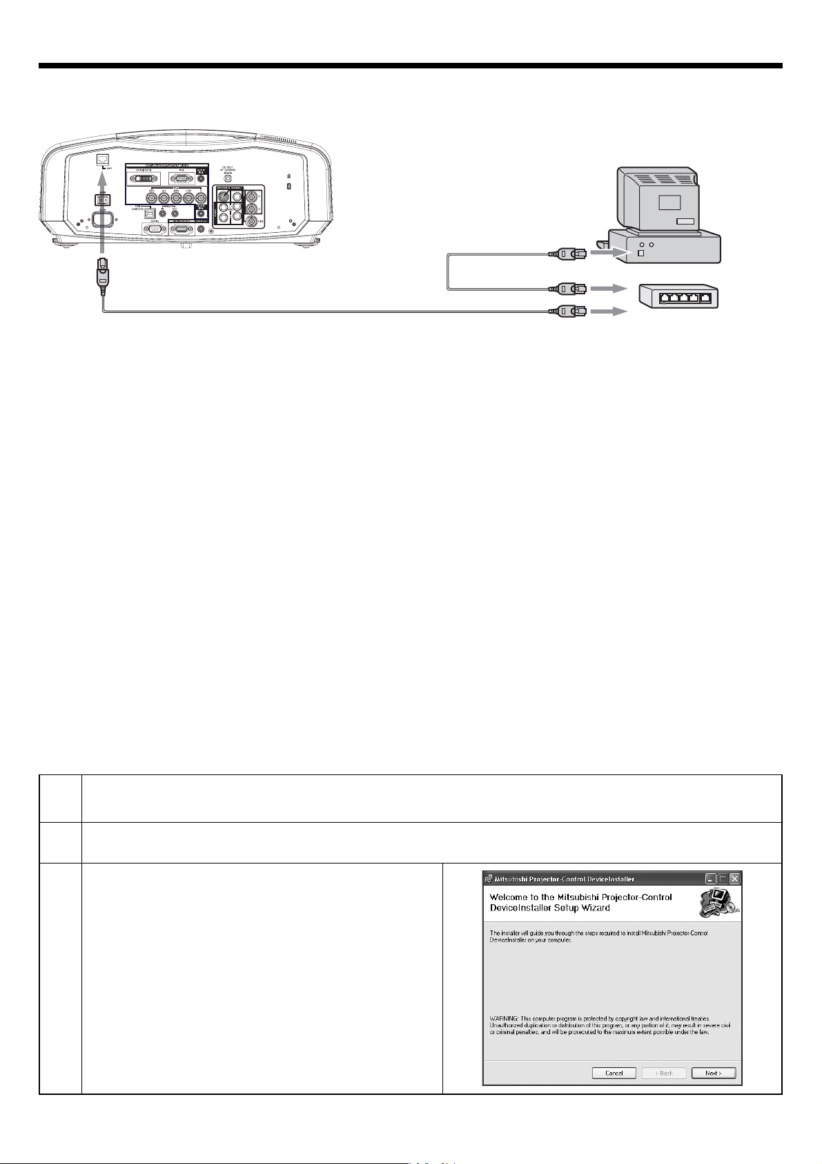
Connection
Computer
LAN cable (option)
(100BASE-TX or 10BASE-T should be
supported.)
to LAN terminal
LAN cable (option)
(100BASE-TX or 10BASE-T should be supported.)
• Use a straight-through category-5 cable for LAN connection.
• Don’t touch the metal parts of the LAN connector and LAN cable because static electricity may be discharged
from your body, causing damage to the projector.
to LAN terminal
External HUB
Installation
Before starting installation, be sure to read “ReadMe.txt” contained in the CD-ROM.
1
2
3
Copy three fi les (Installer_Mitsubishi.msi, Setup.Exe, and Setup.Ini) contained in the Tools folder of CDROM to the hard disk of your personal computer.
Double-click the fi le named Setup.Exe.
When the following window appears, click Next.
EN-3
Page 4
Preparation/SetUp (continued)
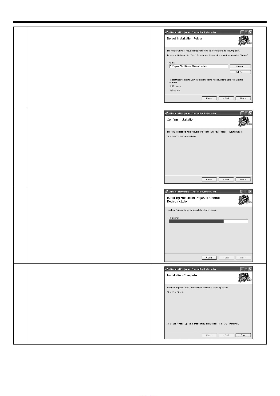
4
5
Select a folder to install the program, and click Next.
Click Next.
6
7
Installation starts.
• The progress of the installation process is
displayed as shown on the right.
When the installation process is completed, click
Close.
How to remove Mitsubishi Projector Control Device Installer
Select [Start] - [Control Panel] - [Add or Remove Programs] - [Mitsubishi Projector - Control Device Installer] and
click [Remove] (in the case of Windows® XP).
EN-4
Page 5
Preparation/SetUp (continued)
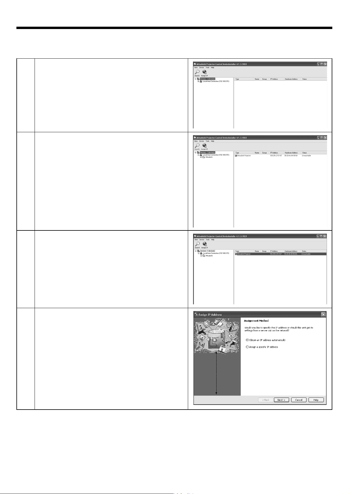
Setting the IP address of the projector
Before setting the IP address, check that the projector has been LAN-networked and turn on the main power of the
projector.
1
2
Start the Projector-Control Device Installer.
Select [Start] - [All Programs] - [Mitsubishi] -
・
[Mitsubishi Projector - Control Device Installer] (in
®
the case of Windows
Click the Search button.
• Mitsubishi projector is recognized.
(Note 1)
When Mitsubishi projector isn’t recognized, check
the following.
• The fi rewall function has been disabled. (When it
has been enabled, search may not be conducted.)
• The personal computer and the projector are on
the same network. (For preventing unauthorized
access.)
• More than one Projector-Control Device Installer
isn’t running.
XP).
3
4
Select a projector and click the Assign IP button.
The Assign IP Address screen appears.
• For automatic IP address setting by the DHCP server, go to page 6. For IP address setting without using the
DHCP server, go to page 7.
EN-5
Page 6
Preparation/SetUp (continued)
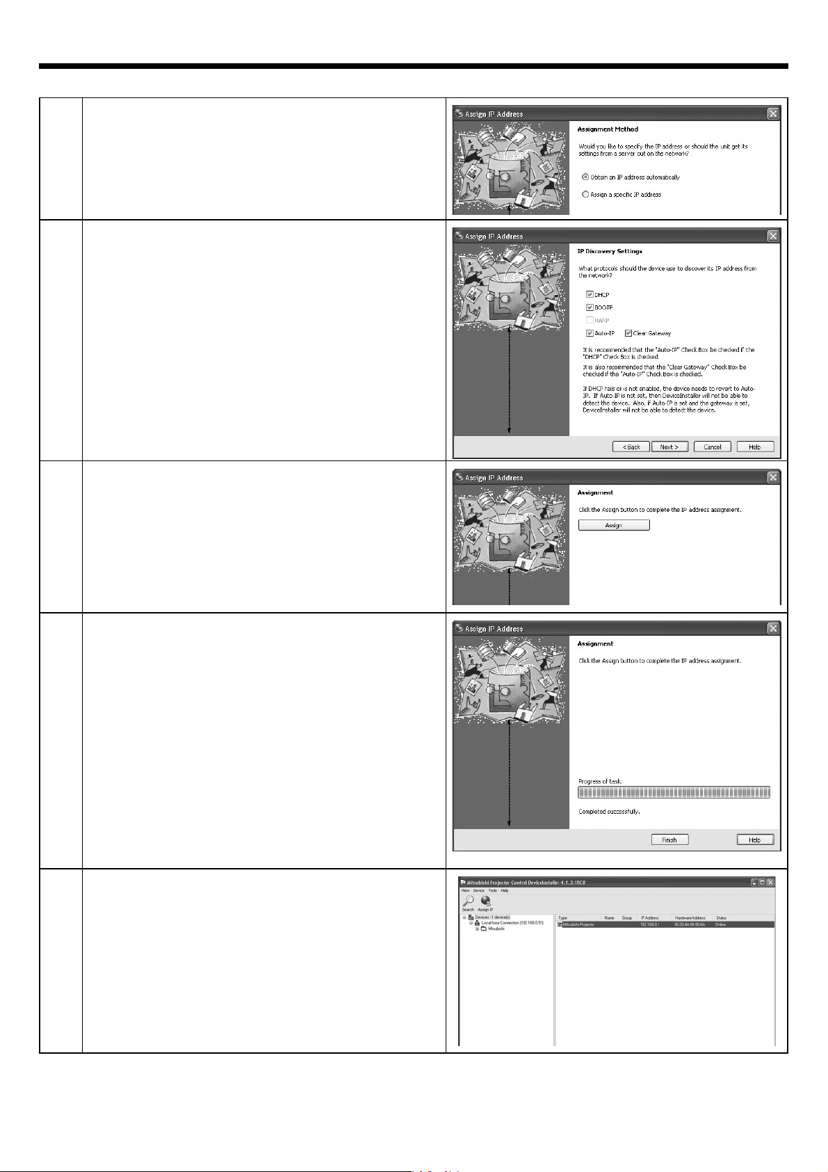
When using a DHCP server
5
6
7
Select [Obtain an IP address automatically] and click
Next.
Click Next.
• Check that the options are marked with check-
marks as shown on the right. Keep them unchanged for normal use.
Click Assign.
8
9
Click Finish.
Click the Search button.
• Check the IP address.
EN-6
Page 7

Preparation/SetUp (continued)
When not using a DHCP server
5
6
7
Select [Assign a specifi c IP address] and click Next.
Enter a fi xed IP address (for example, 192.168.0.1)
and click Next.
Click Assign.
8
9
Click Finish.
Click the Search button.
• Check the IP address you set.
(Note 2)
When using the error/alert e-mail notifi cation function
described later, click the Assign IP button and set the
subnet mask and default gateway correctly.
• For the values of the subnet mask and default
gateway, contact your network administrator.
EN-7
Page 8
Preparation/SetUp (continued)
Telnet setting
Setting of password, display language, LAN control, and PJLink™ certifi cation using telnet.
This section describes how to set the password, display language on the ProjectorView screen, LAN control, and
PJLink™ certifi cation that are necessary for the operation state control tool (commercially available) that uses the
projector operation control/monitor tool ProjectorView and the industry standard PJLink™ protocol.
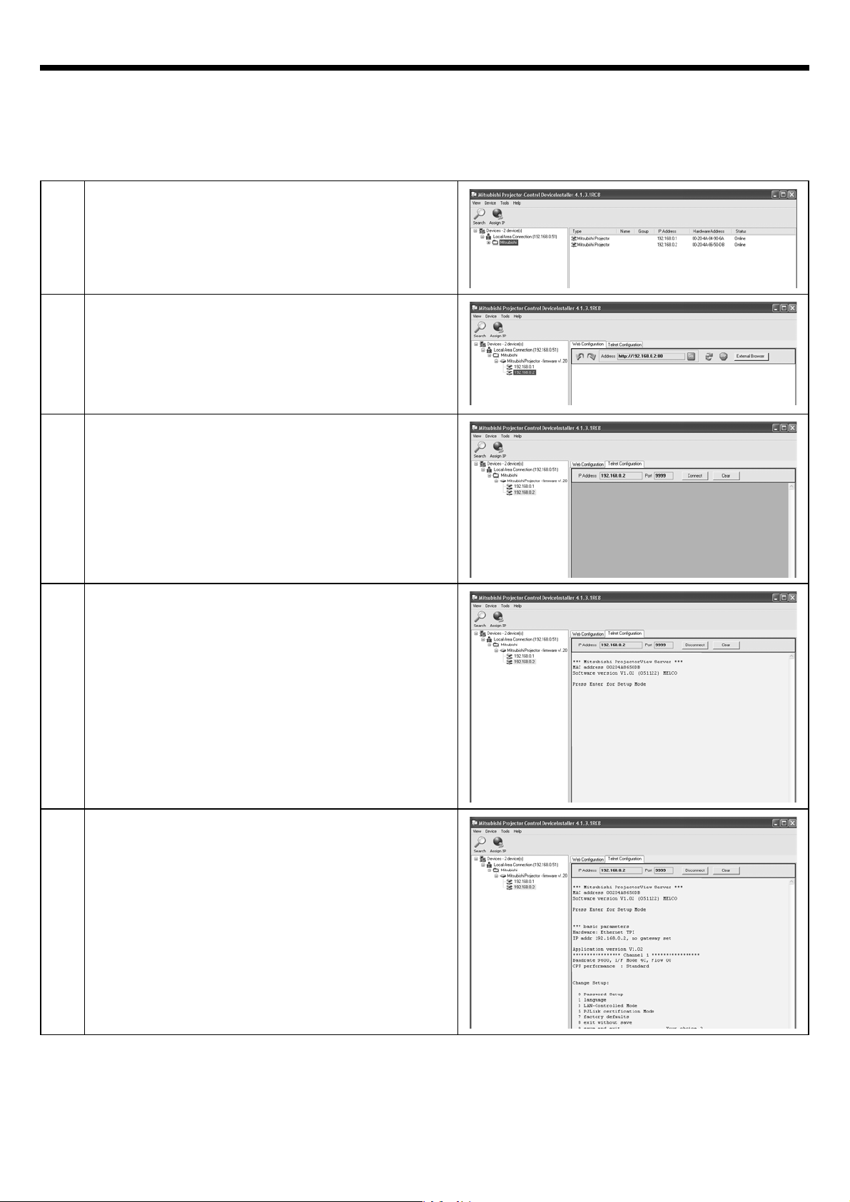
1
2
3
4
Start the Projector-Control Device Installer.
• Select [Start] - [All Programs] - [Mitsubishi] -
[Mitsubishi Projector - Control Device Installer] (in
®
the case of Windows
Press the + buttons on the left pane to expand the
tree structure until the IP address you set appears.
Click the Telnet Confi guration tab.
Select the Connect tab. Press the Enter key within
5 seconds after the message shown on the right
appears.
• When it passes 5 seconds without any operation
on this screen, the screen is shaded and no key
operation is accepted. In this case, click the
Connect button again to continue setting.
XP).
5
The setting menu appears.
EN-8
Page 9

Preparation/SetUp (continued)
Setting the password (Password Setup)
1
2
Enter “0” and press the Enter key.
Enter a new password (example: “proj2000“) and press
the Enter key. (Default password is MITSUBISHI.)
Setting the display language of ProjectorView (language)
1
2
Enter “1” and press the Enter key.
Enter “0” for English or “1” for Japanese.
EN-9
Page 10
Preparation/SetUp (continued)
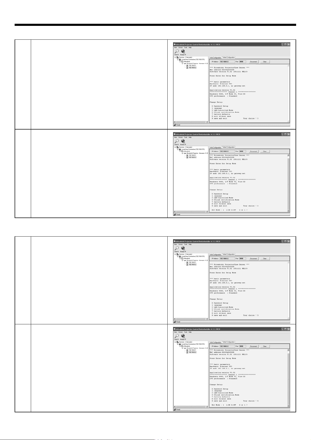
Setting the LAN control (LAN-Controlled Mode)
1
2
Enter “3” and press the Enter key.
To enable the e-mail notifi cation function of ProjectorView, enter 1 and press the Enter key. (Default is OFF (0).)
(See pages 12 - 15 for ProjectorView function.)
Setting the PJLink™ certifi cation (PJLink certifi cation Mode)
1
2
Enter “5” and press the Enter key.
• When you don’t use PJLink™ protocol
communication, skip this item. (See page 16 for
PJLink™.)
To enable the PJLink™ certifi cation:
Enter “1” and press the Enter key. (Default is ON (1).)
EN-10
Page 11

Preparation/SetUp (continued)
Save and exit
1
2
Enter “9” and press the Enter key.
The setting screen is shaded and the setting process
completes.
Because the password, display language, LAN control, and PJLink™ certifi cation are set using the telnet function,
•
you can also set them on the command prompt window of the personal computer. Enter the following command and
press the Enter key.
> telnet IP address you set 9999
[“>” shows a prompt.]
When setting menu appears, perform the setting procedure as described above.
(Note 3 )
Check that the port number “9999” isn’t blocked by the fi rewall.
EN-11
Page 12

ProjectorView
Using the ProjectorView
This section describes ProjectorView, a tool to control and monitor the projector’s operations by a Web browser.
The major functions of ProjectorView are:
Power on/off
・
Input source switching
・
State information indication (projector’s name, temperature, lamp operation time, error/alert, etc.)
・
E-mail notifi cation in case of error/alert
・
How to start up
1
2
Start the Projector-Control Device Installer.
• Select [Start] - [All Programs] - [Mitsubishi] -
[Mitsubishi Projector - Control Device Installer] (in
®
the case of Windows
Expand the tree structure on the left pane until the IP
address you set appears.
XP).
3
4
Select the WEB Confi guration tab.
Click the External Browser button or Go button.
External Browser button:The browser starts on a separate window.
Go button
(Note 1 )
• You can start ProjectorView by directly entering the URL of the Web browser “http://IP address you set”
• When you are using a proxy server, don’t enable the proxy when accessing this IP address.
instead of by clicking the External Browser button.
:The browser starts on the Projector-Control Device Installer window.
EN-12
Page 13

ProjectorView (continued)
5
6
The password input screen appears. Enter the
password you set.
• The default password is MITSUBISHI.
(Note 2)
If you input a wrong password three successive
times, the Web browser is closed. In this case, repeat
from step 1.
The ProjectorView main screen appears.
• Some buttons may not be displayed. In this case,
select [Start] - [Control Panel] - [Java Plug-in] and
disable the cache.
[ProjectorView main screen]
Press to display the Setup window. (See page 15.)
Press to control the projector. For
the functions of these buttons,
see the user guide of the projector.
Failures in the projector are indicated with dots. When you place
the mouse cursor to a dot, the
indicated failure is described in
the box at the bottom.
EN-13
Page 14

ProjectorView (continued)
VIRTUAL REMOTE controller
Put a checkmark in the box of the Virtual remote enabled on the ProjectorView main screen, and click the VIRTUAL
REMOTE button. The following Virtual Remote window appears.
For the functional descriptions of each button, see the user manual of the projector.
E-mail notifi cation function
In case of an error or abnormality in the projector, e-mail notification is automatically sent to the designated
address to notify of the error or abnormality.
To use this function, perform the following steps.
1 Enable the LAN control function. (See page 10.)
2 Set the SMTP IP address, E-mail address, E-mail host, and E-mail from.
Once the above-mentioned items are set, the e-mail notifi cation function remains enabled even when the browser
(ProjectorView screen) is closed.
Example of notifi cation: Alert on lamp life end
ProjectorView Alert:
The lamp has reached its maximum usage. Replace the lamp and reset lamp counter. See user guide for complete
instructions.
Projector name : abc
Projector model : XD2000U
Projector location : 10Factory-5F
Serial number : 12345
Operating hours : 2146 hours and 43 minutes
Lamp hours : 5000 hours and 0 minute
Installation date: 2005/06/02
Last lamp replacement date: 2005/07/15
Last maintenance date: 2005/08/03
(Note 3)
• In case of a command error, e-mail notifi cation isn’t sent.
• When the LAN control is enabled, serial RS-232C commands may not be transmitted.
• You can’t control the LAN/serial RS-232C commands for about 10 seconds after turning on the main power of the
projector.
• When commands for LAN control and for RS-232C control are issued at the same time, the LAN control command
overrides the RS-232C control command.
• While a test pattern is displayed or a password is entered, you can’t change the lamp mode and enable and disable
the MUTE function.
• Response may be delayed depending on the operating state of the projector.
• The DHCP mode may not operate with certain devices (routers etc.).
• When you turn on the projector by pressing the ON/OFF button on the ProjectorView main screen, other commands
are not accepted for about 1 minute.
To use the e-mail notifi cation function, confi gure the initial settings in advance as described on the next page.
EN-14
Page 15

ProjectorView (continued)
Initial setting
To load information on the projector such as model name and lamp operating time, set the projector data in
advance. Click the SETUP button on the ProjectorView main screen. The Projector Setup screen appears. Enter
data according to the description of each setting item.
(Note 4)
You can’t change the Projector model, Serial number, Operating hours, and Lamp hours.
Each setting item is described as follows:
Projector name* Name to identify the projector
Projector model Model name of the projector
Projector location* Location of the projector
Serial number Serial number of the projector
SMTP IP address* IP address of the SMTP server used for e-mail transmission
E-mail address*
E-mail host* User-defi ned string displayed at the Internet header of e-mail message(Example: user
E-mail from* Sender of alert notifi cation e-mail(Example:
Operating hours Cumulative projector operating time
Lamp hours Cumulative lamp operating time calculated on the “Low” lamp mode basis.
Installation date* Date when the projector was installed
Last lamp replacement date*
Last maintenance date* Date when the projector was last maintenanced
Virtual remote enabled Display or hide the virtual remote controller (Check the box to display.)
* ) For data entry, use alphanumeric characters and symbols
(Note 5)
When the “Standard” lamp mode is selected, the indicated lamp operating time may exceed the indicated
operating time. For example, when you use the projector in the “Standard” mode for 2 hours, the lamp operating
time is indicated as 5 hours.
e-mail address to receive alert notifi cation e-mail (Example: administrator@XXX.XXX.XXX
PJView@
Date when the lamp was last replaced
(+ - / = @ * _ ! ? . , ; : # $ % & ( ) | < > [ ] { } " ')
XXX
Example: 192.168.0.1
(
.XXX.XXX
)
)
)
)
.
EN-15
Page 16

Support for the PJLink™ function
This projector supports standard protocol PJLink™ for projector control and you can control and monitor projector’s
operations using the same application among projectors of different models and different manufacturers.
To use this function, perform the following steps.
1 Enable the LAN control function. (See page 10.)
2 Set the PJLink™ certifi cation properly according to the setting of the PJLink™ application to be used. (See page 10.)
Supported commands
The table below shows commands to control the projector using the PJLink™ protocol.
Command Description Remark (Parameter)
POWER Power control 0 = Standby
1 = Power on
POWR? Inquiry about the
power state
INPT Input switching 11 = RGB1
INPT? Inquiry about input
switching
AVMT Mute control 30 = Video and audio mute disable
AVMT? Inquiry about the
mute state
ERST? Inquiry about the
error state
LAMP? Inquiry about the
lamp state
INST? Inquiry about the
available inputs
NAME? Inquiry about the
projector name
INF1? Inquiry about the
manufacturer name
INF2? Inquiry about the
model name
INF0? Inquiry about other
information
CLSS? Inquiry about the
class information
• This projector is fully compliant to the specifi cations of JBMIA PJLink™ Class 1. It supports all the commands
defi ned by PJLink™ Class 1, and the compliance has been verifi ed with the PJLink™ standard specifi cations
Version 1.0.
0 = Standby
1 = Power on
2 = Cooling down
3 = Warming up
12 = RGB2
21 = VIDEO
22 = S-VIDEO
31 = DVI-D
31 = Video and audio mute enable
1st byte: Fan error, 0 to 2
2nd byte: Lamp error, 0 to 2
3rd byte: Temperature error, 0 to 2
4th byte: Cover open error, 0 to 2
5th byte: Always 0
6th byte: Other error, 0 to 2
0 to 2 mean as follows:
0 = No error detected, 1 = Warning, 2 = Error
1st value (1 to 5 digits): Cumulative lamp
operating time
2nd value: 0 = Lamp off, 1 = Lamp on
The following value is returned.
“11 12 21 22 31”
The projector name set on the ProjectorView
Setup window is returned.
“MITSUBISHI” is returned.
“XD2000U” or "XD1000U" is returned.
“1” is returned.
(Note 1)
• The above-mentioned control may not be performed correctly or the monitoring data may not be obtained correctly in
the following conditions:
• During standby.
• During input source switching.
• During command processing.
• Before the splash screen disappears after the power is turned on.
• Use 1 controller to control/monitor 1 projector.
• When you monitor the projector’s operating state regularly using this function, issue inquiry commands at intervals of
at least 1 minute.
• For the specifi cations of PJLink™, access to the Web site of Japan Business Machine and Information System
Industries Association (JBMIA)
.
EN-16
Page 17

Support for the PJLink™ function (continued)
[Notes on Instant Shut Down ]
Instant shutdown of the projector during control using the network function may cause ProjectorView to fail to
display data correctly.
• The operating time and temperature may not be displayed correctly. In this case, close the browser, recognize this
projector using Mitsubishi Projector Control Device Installer, and then start the browser again. (Refer to “How to start
up” of ProjectorView.)
• When you use the e-mail notifi cation function only, no special action is required.
[Terms and defi nitions]
For detailed descriptions, see commercial books.
Te rm D efi nition
DHCP
Gateway A server (or router) to communicate across networks (subnets) that are divided
IP address Numerical address to identify networked computers.
MAC address Abbreviation for Media Access Control address. MAC address is a unique ID
Subnet mask A value to defi ne the number of bits used for a network address of a divided
Telnet A virtual terminal protocol to log in to and control a remote computer.
URL Abbreviation for Uniform Resource Locator. URL is a unique Internet address of
Abbreviation for Dynamic Host Configuration Protocol. This protocol
automatically assigns IP addresses to networked devices.
by subnet mask.
number assigned to each network adapter, based on which data are sent and
received between network adapters.
network (or subnet) in an IP address.
each Web page.
EN-17
 Loading...