

Page 1

TECHNICAL INFORMATION MANUAL
EVOLUTION-VII
Pub. No. N0104CT9A
www.TuningEvo.Club
Page 2

GROUP INDEX
TECHNICAL
INFORMATION
MANUAL
FOREWORD
This manual has been prepared as an introduction
to the specifications, features, construction, functions, etc. of the newly developed LANCER EVOLUTION-VII. Please read this manual carefully so that
it will be of assistance for your service activities.
Please note that the following service manuals are
also available and should be used in conjunction
with this manual.
WORKSHOP MANUAL S0105CT9A
All information, illustrations and product descriptions contained in this manual are current as of the
time of publication. We, however, reserve the right
to make changes at any time without prior notice or
obligation.
GENERAL .......................
ENGINE .........................
POWER TRAIN ..................
DRIVE-CONTROL
COMPONENTS ..................
BODY ...........................
EXTERIOR ......................
INTERIOR .......................
EQUIPMENT .....................
0
1
2
3
4
5
6
7
The EVOLUTION-VII is sold exclusively through
RALLIART Inc. Since the EVOLUTION-VII is a rallybased model, it will not be warranted and will not be
homologated for general production. Therefore, any
service matters on the EVOLUTION-VII should be
inquired to RALLIART Inc. as usual.
E Mitsubishi Motors Corporation April 2001
Page 3

NOTES
Page 4

GENERAL
CONTENTS
0-1
HOW TO USE THIS MANUAL 2..............
Model Indications 2............................
TARGETS OF DEVELOPMENT 2..............
PRODUCTS FEATURES 2....................
TECHNICAL FEATURES 4....................
Exterior 4.....................................
Interior 5......................................
Body Dimensions and Spacious Cabin 6.........
Aerodynamic Performance 6....................
Active Center Differential (ACD), Active Yaw
Control (AYC) 7................................
Engine 8......................................
Transmission 8.................................
All-wheel Independent Suspensions 8............
Safety 10......................................
Equipments 13.................................
Serviceability and Reliability 13..................
VEHICLE IDENTIFICATION 14.................
MAJOR SPECIFICATIONS 15.................
Page 5

0-2
GENERAL -
How to Use This Manual/Targets of Development/Product Features
HOW TO USE THIS MANUAL
MODEL INDICATIONS
The following abbreviations are used in this manual for identification of model types.
MPI: Indicates the multipoint injection, or engine equipped with the multipoint injection.
DOHC: Indicates an engine with the double overhead camshaft, or models equipped with such an engine.
M/T: Indicates the manual transmission, or models equipped with the manual transmission.
A/C: Indicates the air conditioner.
TARGETS OF DEVELOPMENT
A new competitive device in addition to technology established in the previous motor sport events to
improve potential performance as well as outward and inward appearance with a sophisticated view to
represent a high performance sedan of the next generation has been featured to improve the image
of Mitsubishi brand.
Furthermore, enhancement of competitiveness as well as driving performance in various motor sport
events has been sought.
PRODUCT FEATURES
Outward and inward appearance
to represent a
high performance sedan of
the next generation
The most outstanding engine
and power performance in the
class
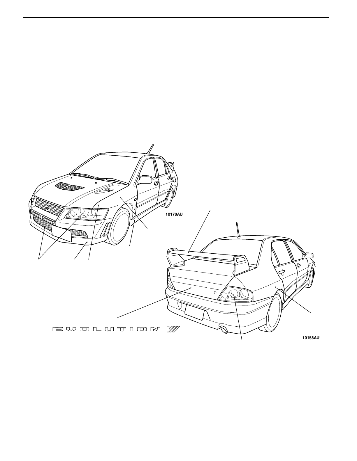
(1) Exterior with sophisticated and fearless expression
D Multi-lighted headlamp and rear combination lamp exclusively used
for EVOLUTION-VII
D Front bumper with large cooling air inlet
D Incorporate blister fender and overwhelming large - sized tyre
D Large- sized and light weight rear spoiler with variable elevation angle
that can be adjusted at 4 points
D Front bumper extension and side sill extension
D Large- sized under cover equipped (for improvement of aerodynamic
and cooling performance in drive system)
(2) Interiors with athletic feeling
D Light weight backet newly designed by RECARO seat (adoption of
silk waving cloth with functionality)
D Steering wheel newly designed by MOMO
D Multi- functional sports meter (with permanent illumination to be visible
in the day light)
(1) Fine tuned engine that provides improved output at all ranges:Maximum
output 280 PS (206 kW) and maximum torque 39 kgfSm (383 NSm)
D mprovement of turbo charger
D Enlarged Intercooler and oil cooler
D Automatic injection control 3 -nozzle intercooler spray
(2) Drive system with high reliability to deal with increased engine torque
D Reinforcement of transfer, propeller shaft, and drive shaft
Page 6

GENERAL -
Product Features
0-3
Further improvement in handling
performance
made by enhancement of the
marginal performance
(1) Mitsubishi original revolutionary technology with all wheel control
D Newly developed active center differential system (ACD) (to be
compatible with steering response to cornering and rising traction
performance)
D Improvement of marginal performance in cornering made by integrated
control of ACD{active yawing control (AYC)
(2) Optimally tuned suspension to be adjusted to the new dimensions has
improved cornering performance.
D Extended length of wheel base (+115 mm), enlarged width of treads
(front: +5 mm, rear: +10 mm)
D Increased suspension stroke in the compression side
(front:+15 mm, rear: +5 mm)
D 235/45ZR17 tyres adopting half- radial structure and newly developed
high performance high grip compounds
NOTE
Figures in the parentheses indicate the numbers compared with those
of EVOLUION-VI.
(3) High rigidity body to sustain high marginal performance
(bend rigidity: increased by 50 %, torsion rigidity: equal to that of
EVOLUTION-VII)
D Suspension mounting, fortification of body frame connections, addition
of reinforcements (approximately 20 locations), and addition of welding
spots
D High rigidity 3- point mounting strut tower bar
D Rear end cross bar<RS>
D Aluminum hood and fender attached
Revolutionary
braking system
to correspond
with high marginal performance
(1) Sporty type 4ABS (improved braking stability derived from braking control
in both sides at driving in sports mode)
(2) EBD system for EVOLUTION-VII (improvement in deceleration
performance)
(3) Featuring Brenvo made front 17- inch ventilated disc (opposite differential
diameter 4 - piston type) and rear 16- inch ventilated disc (opposite
2- piston type)
Page 7
0-4
GENERAL - Technical Features
TECHNICAL FEATURES
EXTERIOR
DESIGN FEA TURES
The 7th generation EVOLUTION has acquired the
image of “high performance sports sedan” equipped
with guaranteed quality and fearless determination
as “high quality driving sedan” in addition to the
rally image of the previous generations.
(1) Aggressive and overwhelming front mask with
multi- lighted headlamps, large-sized inlet
bumper grill, and side outlet
(2) Improved maneuvering capability of the vehicle
at the corners by cutting a large portion of the
front corner
(3) Exclusive blister fender to appeal good road
hanging (traction characteristics) and brisk
driving capability
(4) Front -side sill extension and wing - type rear
spoiler to emphasize the high aerodynamic
performance
(5) Clear type rear combination lamp to appeal
sporty feeling and guaranteed quality
(6) Attaching the newly designed “EVOLUTION
VII” emblem with sharp and sporty image
(1)
(4)
(4)
(3)
(4)
(2)
(3)
(6)
(5)
Page 8
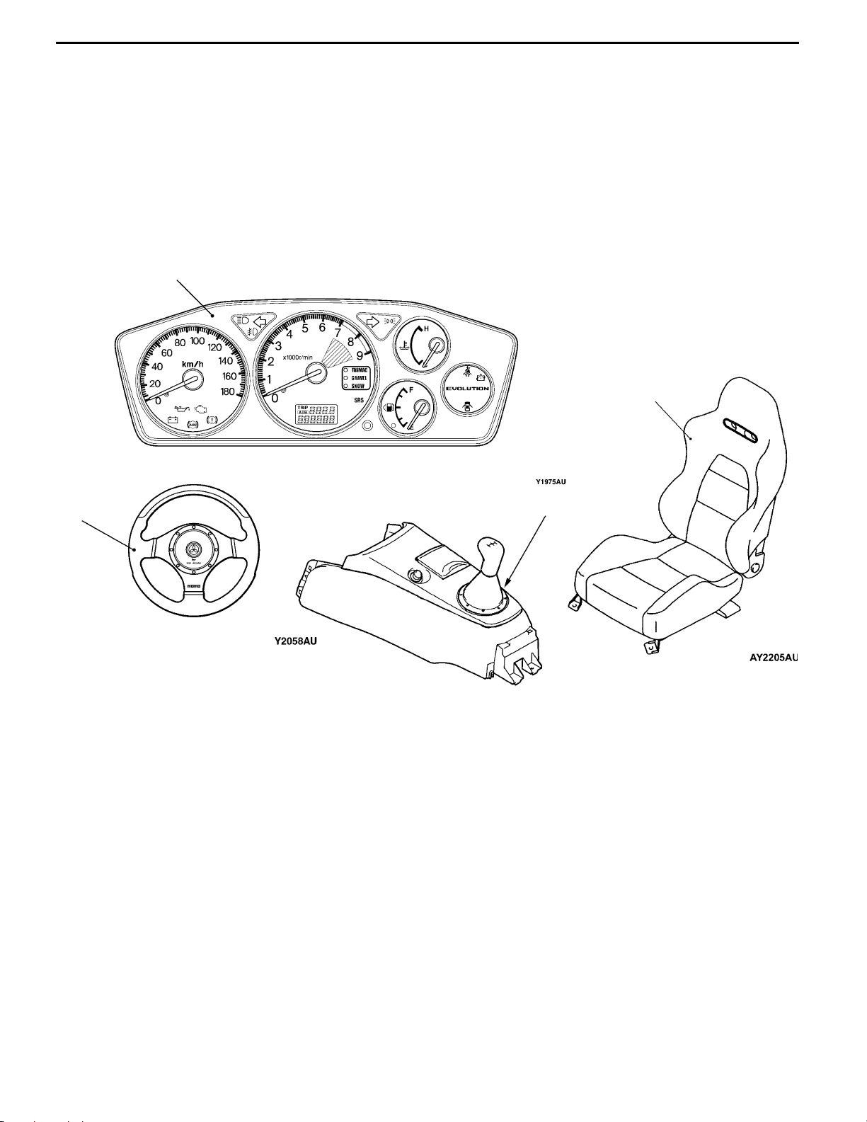
GENERAL - Technical Features
INTERIOR
DESIGN FEA TURES
High performance interior to provide an impression
of sports minded vehicle as the 7th generation
EVOLUTION
(1) Combination meter exclusively for EVOLU-
TION-VII with a configuration of a circular
tachometer in the center and thick bezels
(partitions between meters) with discreet design
create appeal for fearless determination and
sporty feelings.
(1)
0-5
(2) The Mitsubishi original design made by MOMO
used for the steering has the same design used
for horn pad as the shift lever to express
integration of the image and high performance
interior.
(3) The Mitsubishi original design made by Recaro
used for the front seat has a sewing line
surrounding circumference of the sides to
emphasize the good holding.
(3)
(2)
(2)
Page 9
0-6
ith
ith
GENERAL - Technical Features
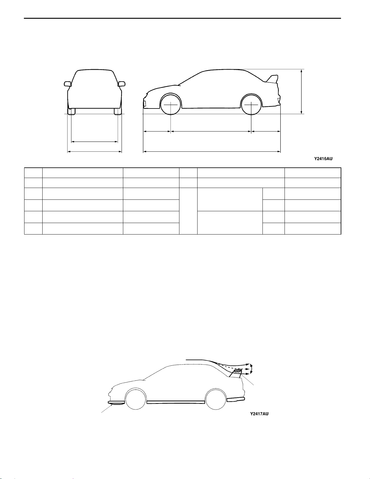
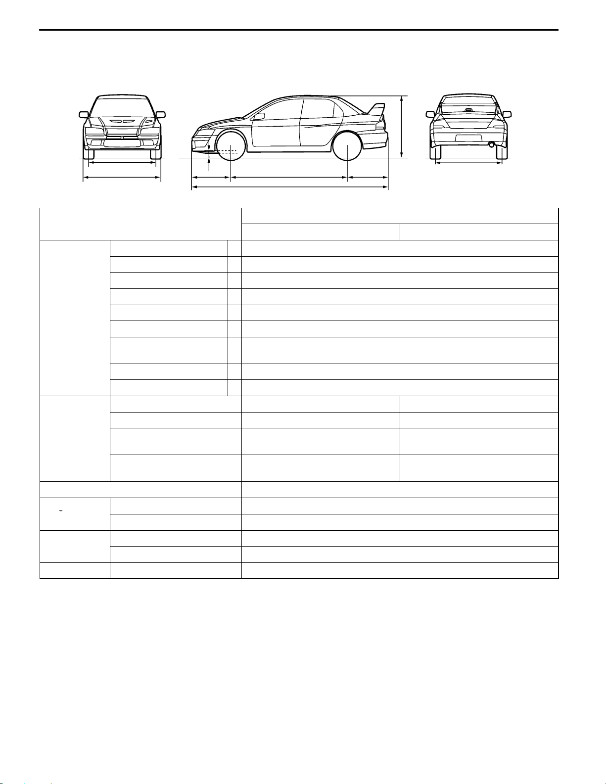
BODY DIMENSIONS AND SPACIOUS CABIN
Body Dimensions
The dimensions of the EVOLUTION-VII except for the overall width have been altered in comparison
with those of EVOLUTION-VI.
3
5
7
2
No. Item Dimensions mm No. Item Dimensions mm
1 Overall length 4 455 (+105) 6 Rear overhang 935 ( - 15)
2 Overall width 1 770 (±0)
3 Overall height 1 450 (+45)
4 Wheel base 2 625 (+115)
5 Front overhang 895 (+5)
7 Tred
4
1
<Vehicles w
235/45ZR17tyres>
Tred
<Vehicles w
205/65R15tyres>
6
Front 1 515 (+5)
Rear 1 515 (+10)
Front 1 500 (+5)
Rear 1 500 (+10)
NOTE
Figures in the parentheses indicate the values in comparison with those of EVOLUTION-VI.
AERODYNAMIC PERFORMANCE
Deterioration of aerodynamic performance accompanied with enlargement of the body size has been
suppressed by attaching a large -sized under cover on the lower part of the engine compartment, optimizing
elevation angle setting of rear spoiler.
(1) Under cover
A large -sized under cover is designed for compatibility of reduction of air resistance and reduction
of lift.
(2) Rear spoiler
Lift control by attaching elevation angle adjustable rear spoiler and optimizing attached position of
the spoiler are designed for reduction of air resistance.
(2)
(1)
Page 10
GENERAL - Technical Features
0-7
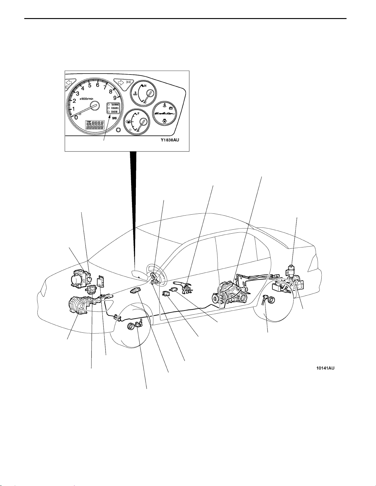
ACTIVE CENTER DIFFERENTIAL (ACD), ACTIVE YAW CONTROL (AYC)
ACD, which is designed for improving drive characteristics by electronically controlling center
differential movement, and AYC, which has been adopted since EVOLUTION-IV are featured by
combing two systems for integrated control so that further improvements in driving performance can
be achieved.
ACD mode indicator lamp
AYC torque transfer
differential
Parking brake switch
Steering wheel
sensor
Throttle position sensor (TPS)
ABS-ECU
ACD transfer
Engine- ECU
4WD-ECU
Longitudinal
G sensor
ACD mode switch
Stop lamp switch
Reserve tank
Hydraulic unit
assembly
Lateral G sensor
Wheel speed sensor
Wheel speed sensor
Page 11

0-8
GENERAL - Technical Features
ENGINE
The turbo charger specifications have been
optimized by reducing the size of the turbine nozzle
diameter to increase the engine torque at
low- middle speed range as well as high speed
range.
TRANSMISSION
Implementation of fortifying each part to deal with
the increased engine torque and revision of the gear
ratio of the standard transmission are intended for
further improvement in power performance.
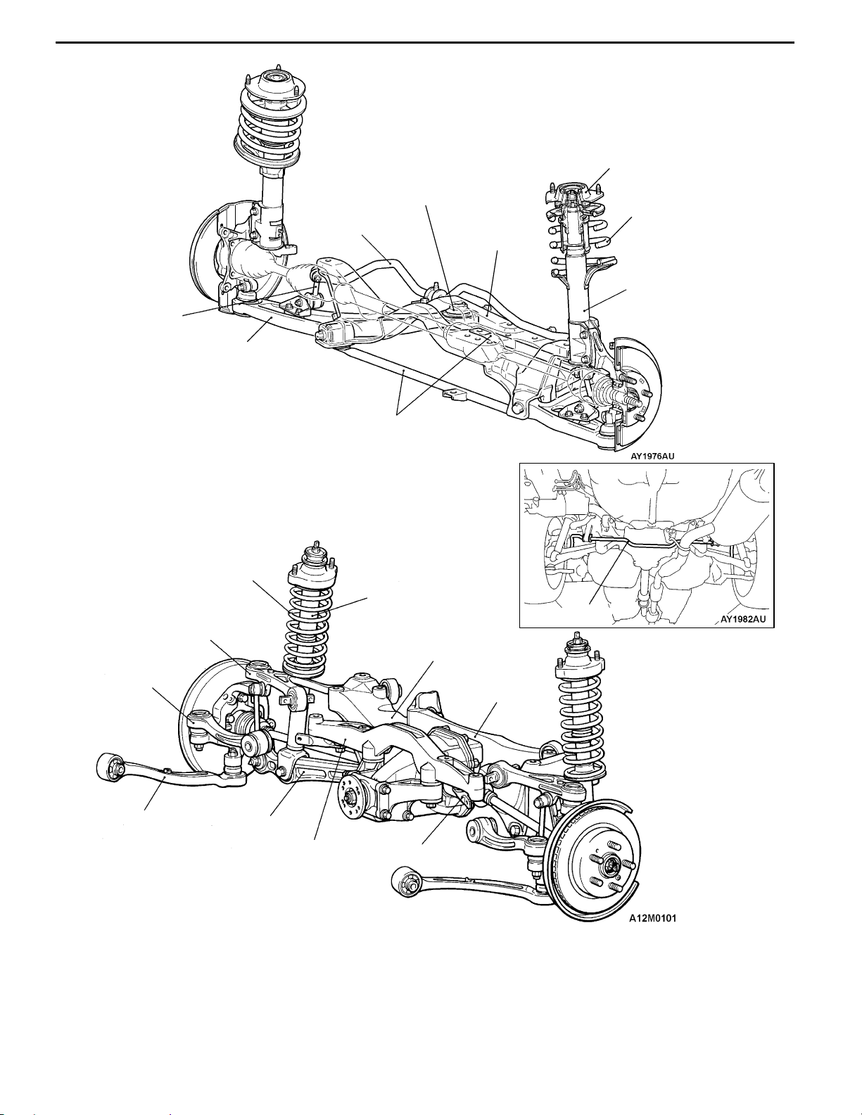
ALL-WHEEL INDEPENDENT SUSPENSIONS
While the popular and rally-proven McPherson strut
front and multi-link rear suspension systems have
basically been retained, they were optimized for
the new model.
The improvements to the front include adding a
crossmember brace to the lower arm mount for
more rigidity, flattening the chassis crossmember,
and realigning the roll center to an ideal height.
As a result, the suspension delivers enhanced
handling and straight-line stability, ride comfort,
grounding characteristics, and roll feel, as well as
less vibrations and noise.
Since adoption of magnesium diecasting rocker
cover and hollow camshaft is intended for light
weight of the upper part of the engine, vibration
of engine- transmission at acceleration can be
reduced to improve the response of the body.
The steering gear’s optimal position ensures
predictably linear toe-in changes.
Each arm of the rear multi-links with trailing arms,
as well as its linkage point and length, was
reevaluated to achieve optimal alignment.
Combined with the wider tracks, higher body rigidity,
and improved damping characteristics of the
bushings and bump rubbers, the suspensions
deliver a supple ride with superb handling stability
for relaxing, effortless control.
Page 12
Stabilizer link
Lower arm
GENERAL - Technical Features
Lower arm bushing
(Pillow ball bushing with rubber)
Stabilizer bar
Crossmember bar
<RS (option), RS-II>
Crossmember
0-9
Strut insulator
Coil spring
Strut assembly
(shock absorber)
Toe control arm
Trailing arm
Coil spring
Upper arm
Lower arm
Differential support
member
Shock absorber
Stabilizer bar
Crossmember
Differential
support arm
Toe control bar <RS>
Page 13
0-10
GENERAL - Technical Features
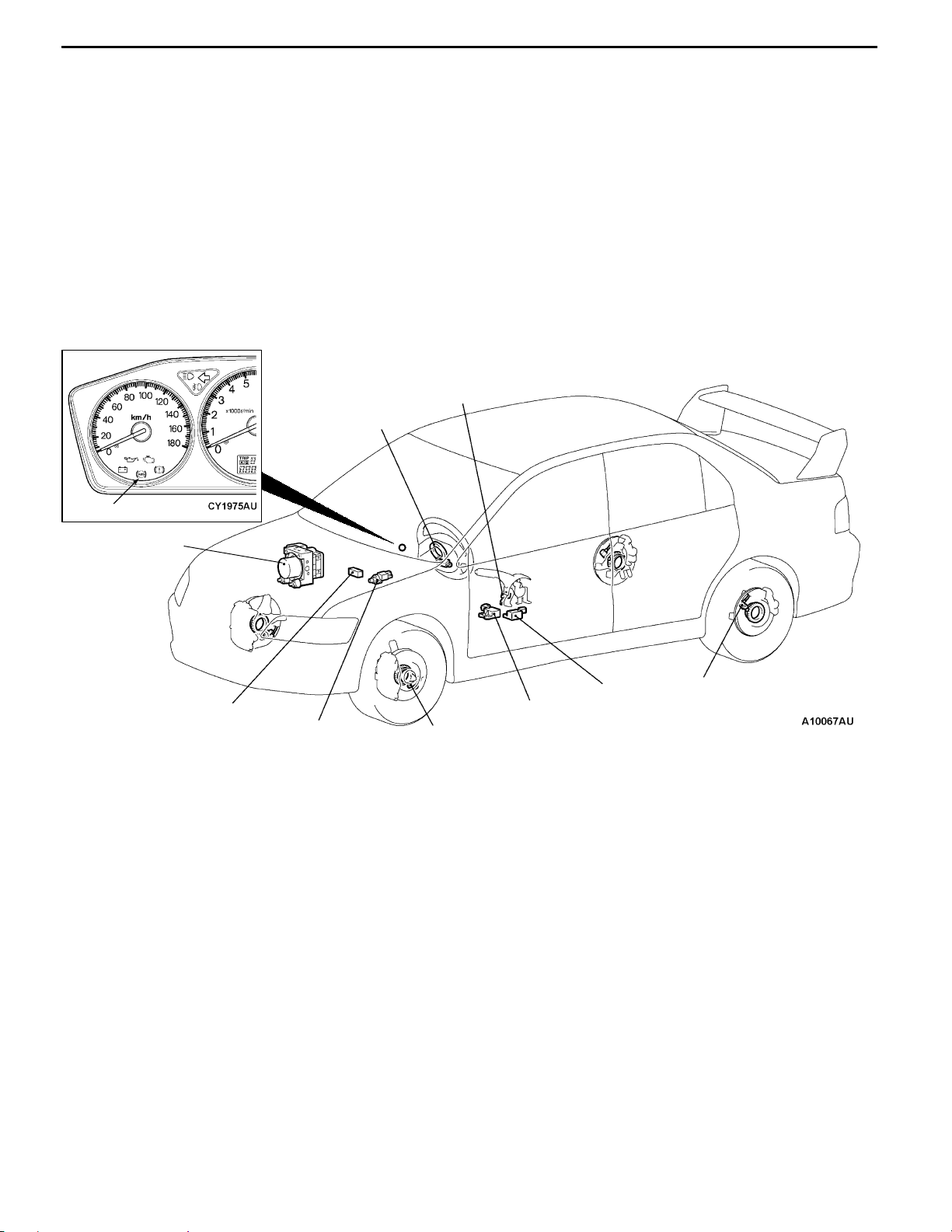
SAFETY
ACTIVE SAFETY
BRAKING SYSTEM
All models feature fade-resistant 14-inch ventilated
discs up front and rear 8-inch drums for sure, linear
stopping power.
A 4-sensor, 3-channel ABS (Anti-lock Braking
System) with EBD (Electronic Brake-force
Distribution) is available. ABS adjusts the braking
pressure of the front wheels independently and
rear wheels together for controlled emergency
braking.
Parking brake switch
Steering wheel sensor
New for the Lancer, EBD works with the ABS
computer to evenly modulate each channel’s
braking pressure for ideal braking force regardless
of load or surface conditions at all times.
ABS warning lamp
Hydraulic unit
(integrated in
ABS-ECU)
Diagnosis connector
Stop lamp switch
Longitudinal G sensor
Wheel speed sensor
Lateral G sensor
Wheel speed sensor
Page 14
GENERAL - Technical Features
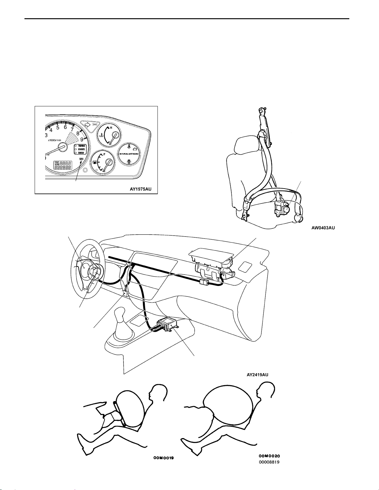
PASSIVE SAFETY
SRS AIR BAGS
Dual SRS (Supplemental Restraint System) front
airbags deploy only upon detection of frontal impact.
When used in combination with the 3-point ELR
seatbelts, they significantly mitigate head and upper
torso injury to front-seat occupants.
SRS warning lamp
0-11
Seat belt with pretensioner featured for the driver’s
and front passenger’s seats is designed for instantly
taking up the slack in the seat belt at the time
of impact to improve restraint effect on a passenger.
It is activated approximately at the same time as
SRS airbag is activated to improve protection effect
on a passenger.
Seat belt with pretensioner
Driver’s side air bag module
Clock spring
Diagnosis connector
Driver’s side Passenger’s side
Front passenger’s side air bag module
SRS- ECU
Page 15
0-12
GENERAL - Technical Features
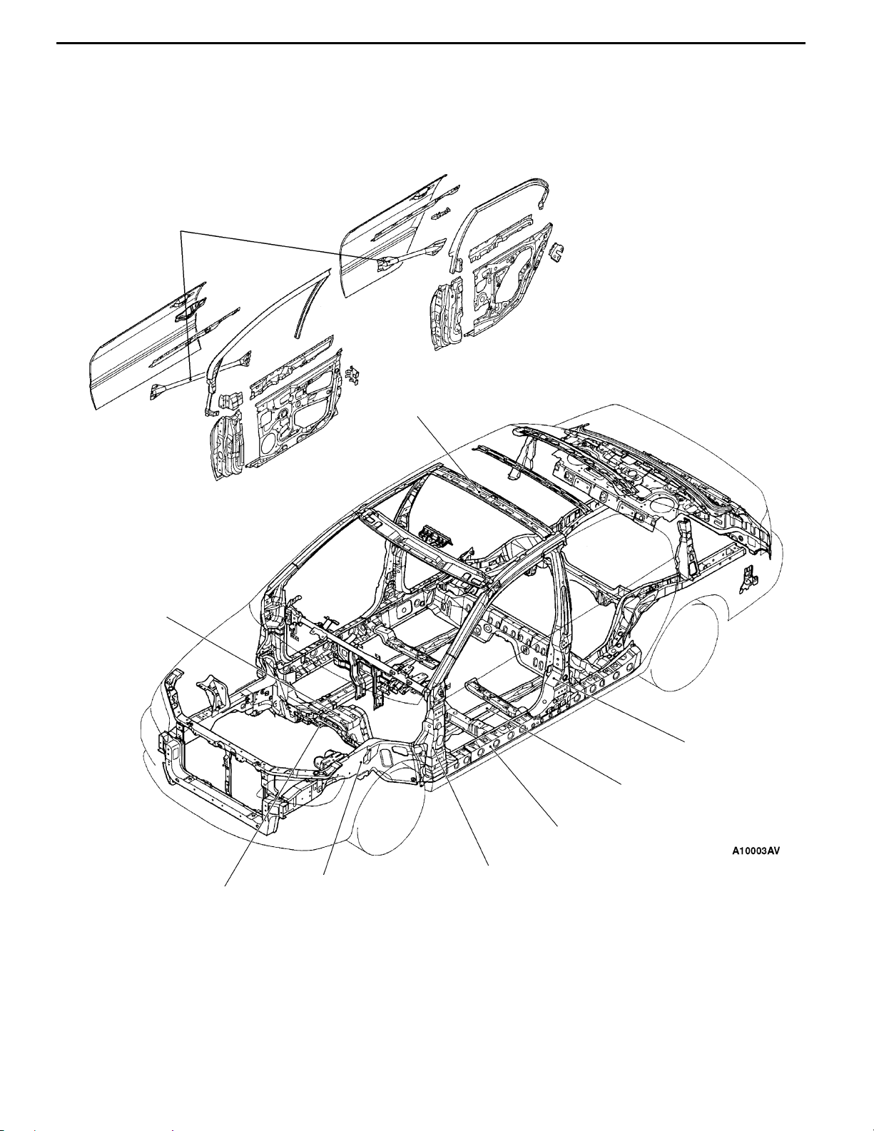
BODY CONSTRUCTION
The EVOLUTION-VII safety-enhanced body
structure comprises front and rear crushable zones
that effectively absorb the impact energy of front
and rear collisions.
Enlarged impact bars
Enlarged cross-section of roof bow
Adding to all-round occupant protection is a
deformation-resistant, highly rigid cabin structure
that features strategic reinforcements plus large
side-door impact bars.
Thicher dash panel lower
Added dash crossmember
Enlarged cross-section and
extended front side member
Reinforced center pillar
Enlarged cross-section and
minimised vertical offset of
front floor side member
Enlarged cross-section
of side sill
Reinforced front pillar
Page 16
GENERAL - Technical FeaturesGENERAL - Technical Features
SAFETY-ENHANCED FRONT SEATS
The front seats are designed to minimise the risk
of whiplash in a collision from the rear.
The headrestraints have been ideally angled
forward, while the seat frame was moved toward
the rear.
OTHER SAFETY FEATURES
D 3-point ELR seatbelts
D Front fog lamps
EQUIPMENTS
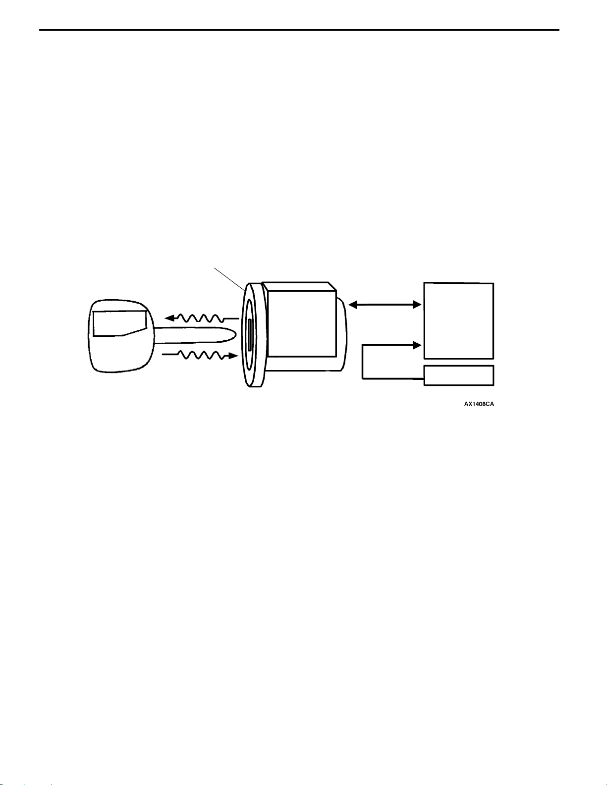
IMMOBILIZER SYSTEM
This system lets the engine be started only when
an encrypted code that is recorded in the ignition
key is the same as an encrypted code that is
Integrated immobilizer-ECU and antenna
Ignition key
Power
Transponder
0-13
In-house tests show a roughly 40% improvement
in occupant injury figures.
D Child-protection rear door locks
recorded in the immobilizer-ECU. Immobilizer
system is equipped as an option.
Start
permission
signal
Engine - ECU
or
Engine A/T-ECU
Encrypted code
Steering lock key
cylinder and immobilizer - ECU
SERVICEABILITY AND RELIABILITY
MAINTENANCE-FREE FEATURES
D Adoption of an auto-tensioner eliminates the
need for timing belt adjustment
ENHANCED DIAGNOSIS SYSTEM
Diagnosis functions have been included for the
following systems, so that it is possible to use the
MUT-II to read the diagnosis codes and service
data and to carry out actuator tests. In addition,
it is also possible to read the diagnosis codes by
the flashing of the warning lamp in some systems.
IMPROVED SERVICEABILITY AND HANDLING
D A one-touch joint type plastic tube has been
adopted for fuel main lines, which makes
removal and installation easier.
MUT- II
Registration
of ignition
key
D Adoption of auto lash adjusters eliminates the
need for valve clearance adjustment
D MPI
D ACD
D AYC
D 4ABS
D SRS air bag
D Simplified Wiring System (SWS)
D A small wiper module, which includes wiper
motor and linkage, has been adopted to
facilitate removal and installation.
Page 17

0-14
16val
)
GENERAL - Vehicle Identification
VEHICLE IDENTIFICATION
MODELS
Model code Class code Grade Engine model Transmission model Fuel supply
system
CT9A SNDFZL/R RS 4G63 (1,997 mL-DOHC-
ves-intercoolerturbo
SNGFZL/R RS-II
MODEL CODE
CT 9 A S N D F L
Z
123456789
No. Items Contents
1 Development CT: MITSUBISHI LANCER
2 Engine type 9: 1,997 mL petrol engine
3 Sort A: Passenger car
4 Body style S: 4-door sedan
5 Transmission type N: 5-speed manual
6 Trim level D: RS
7 Specification engine
feature
W5M51 <4WD-5M/T> MPI
EVOLUTION-VII
transmission
G: RS-II
F: MPI-DOHC
8 Special feature Z: 4WD
9 Steering wheel location L: Left hand
R: Right hand
Page 18
GENERAL - Major Specifications
mm
g
MAJOR SPECIFICATIONS
0-15
8
1
2
Items
Vehicle
dimensions
Vehicle
weight kg
Seating capacity 5
Engine Model No. 4G63
Transmission
Fuel System Fuel supply system MPI
Front track 1 1,500, 1,515
Overall width 2 1,770
Front overhang 3 855
Wheel base 4 2,625
Rear overhang 5 975
Overall length 6 4,455
Ground clearance
(unladen)
Overall height (unladen) 8 1,450
Rear track 9 1,500, 1,515
Kerb weight 1,380 1,420
Max. gross vehicle weight 1,655 1,695
Max. axle weight
rating-front
Max. axle weight
rating-rear
Total displacement mL 1,997
Model No. W5M51
Type 5-speed manual
7
3
CT9A
SNDFZL/R SNGFZL/R
7 140
950 970
705 725
9
4
5
6
*1
*1
NOTE
1
: Vehicles with 17 inch wheels.
*
Page 19

NOTES
Page 20

ENGINE
CONTENTS
1-1
GENERAL INFORMATION 2................
Major Specifications 2.......................
BASE ENGINE 3..........................
Piston 3....................................
Piston Ring 3...............................
LUBRICATION SYSTEM 4..................
Engine Oil Cooler 4.........................
COOLING SYSTEM 5......................
Specifications 5.............................
Construction Diagram 5......................
INTAKE AND EXHAUST 6.................
Air Intake System 6.........................
Exhaust System 9...........................
FUEL SYSTEM 11.........................
Specifications 11............................
Construction Diagram 11.....................
Fuel Tank 12...............................
CONTROL SYSTEM 13....................
System Block Diagram 14....................
Control System Diagram 15..................
List of Component Functions 16..............
Fuel Injection Control 19......................
Idle Speed Control 19.......................
Ignition Timing and Distribution Control 20.....
Radiator Fan Motor Control 20...............
Power Supply and A/C Condenser Fan Relay
Control, Oxygen Senser Heater Control, Air Flow
Senser Filter Reset Control, Alternator Control,
Fuel Pressure Control, Supercharging Pressure
Control, Secondary Air Control 20.............
Fuel Pump Relay Control 21..................
EGR Control and Purge Control 22............
Diagnosis System 22.........................
EMISSION CONTROL SYSTEM 23..........
Emission Control System Diagram 23.........
MOUNT 24................................
Construction Diagram 24.....................
ACCELERATOR SYSTEM 26...............
Construction Diagram 26.....................
Page 21

1-2
ENGINE - General Information
GENERAL INFORMATION
This engine has the same basic structure as the previous 4G63-T/C engine, however, the following
enhancements have been added in order to provide improved performance.
D The piston shape has been changed.
D The width of the piston rings has been reduced in order to reduce engine friction.
D The turbocharger type has been changed.
D An EGR valve has been added.
MAJOR SPECIFICATIONS
Items 4G63-T/C
Total displacement mL 1,997
Bore × stroke mm 85.0 × 88.0
Compression ratio 8.8
Combustion chamber Pentroof type
Camshaft arrangement DOHC
Valve timing Intake opening BTDC 21_
Intake closing ABDC 59_
Exhaust opening BBDC 58_
Exhaust closing ATDC 18_
Maximum output kW/r/min 206/6500
Maximum torque N·m/r/min 383/3500
Fuel system Electronic controlled multipoint fuel injection
Rocker arm Roller type
Auto-lash adjuster Equipped
Page 22
ENGINE - Base Engine
1-3
BASE ENGINE
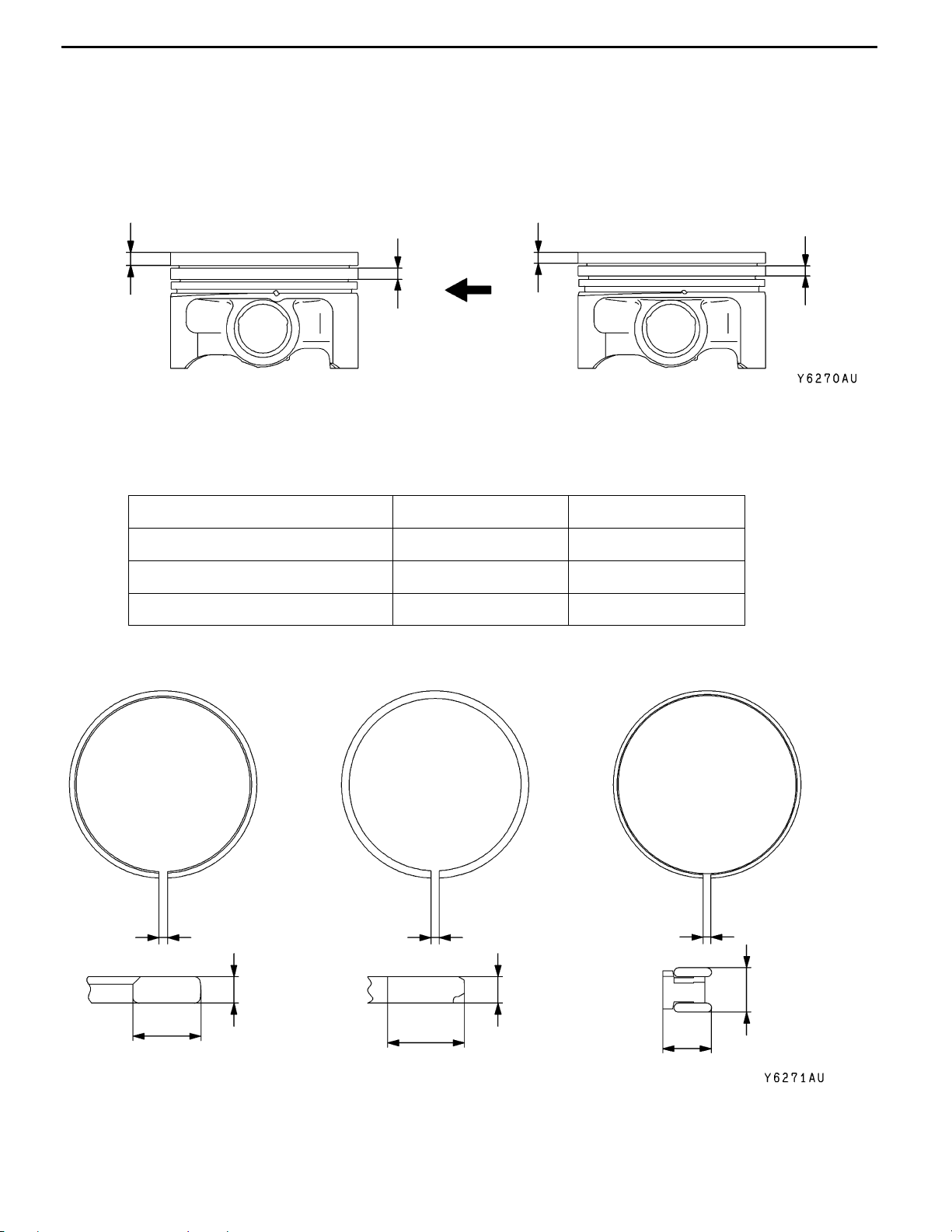
PISTON
The top land height has been changed from 5 mm to 6 mm, and the second land height has been
changed from 4.5 mm to 5 mm.
<OLD>
4.5 mm
6mm
<NEW>
5mm
5mm
PISTON RING
The tension of the rings has been changed as shown in the table below, and the thicknesses of the
No. 2 ring and the oil ring have been reduced in order to provide reduced engine friction.
NEW OLD
PISTON RING No. 1 9.5 N 8.34 N
PISTON RING No. 2 7.0 N 10.49 N
OIL RING 25.0 N 33.34 N
PISTON RING No. 1 PISTON RING No. 2 OIL RING
0.20 ∼ 0.30 mm (New models)
0.25 ∼ 0.35 mm (Old models)
1.2 mm
3.1 mm
3.5 mm (New models)
3.8 mm (Old models)
0.35 ∼ 0.50 mm (New models)
0.40 ∼ 0.55 mm (Old models)
1.2 mm (New models)
1.5 mm (Old models)
2.2 mm (New models)
2.5 mm (Old models)
0.10 ∼ 0.40 mm
2.0 mm (New
models)
2.8 mm (Old
models)
Page 23
1-4
ENGINE - Lubrication System
LUBRICATION SYSTEM
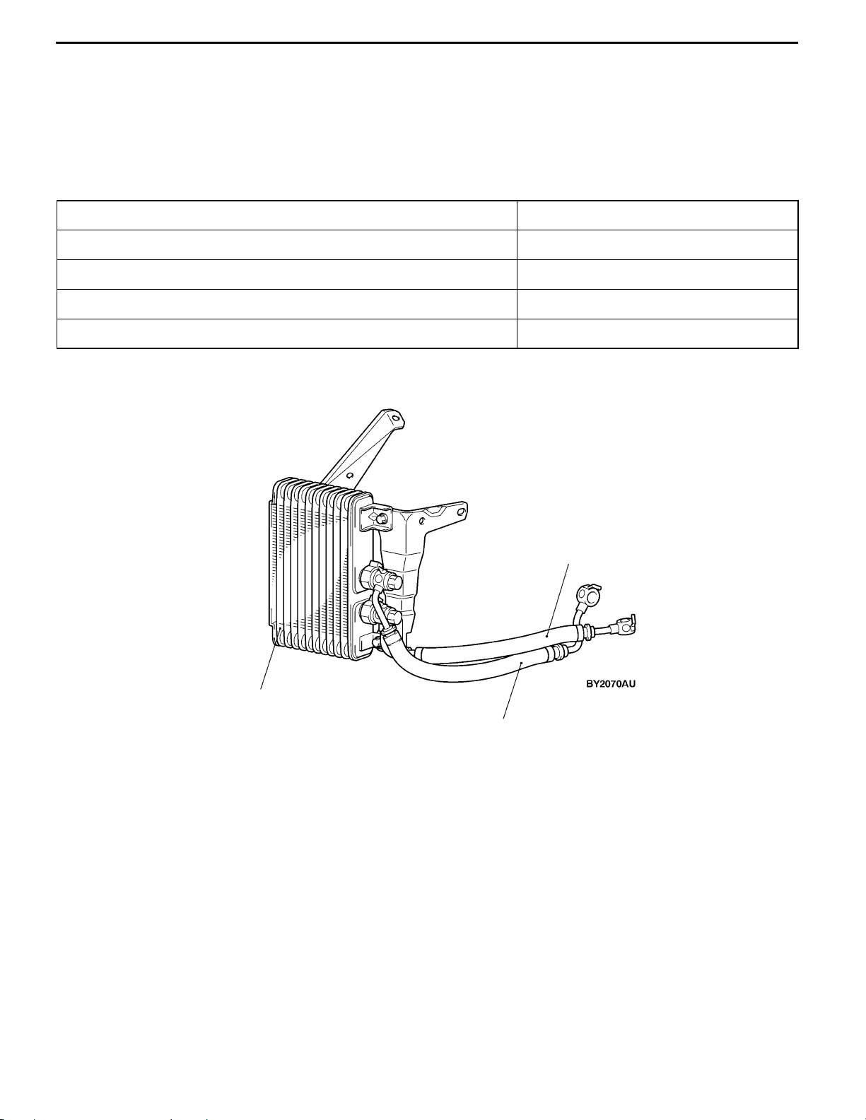
ENGINE OIL COOLER
The drawn cup air-cooled type engine oil cooler has been adopted. The engine oil cooler is installed
below the right head lamp assembly and brings in the air through the oil cooler duct of the front bumper
to cool the engine oil.
SPECIFICATIONS
Items Specifications
Type Drawn cup type
Core size mm (Width × Hight × Thickness) 160 × 200 × 49
Engine oil cooler oil amount L 0.35
Performance kJ/h 29,900
CONSTRUCTION DIAGRAM
Engine oil cooler
Engine oil cooler
return hose
Engine oil cooler
feed hose
Page 24
ENGINE - Cooling System
1-5
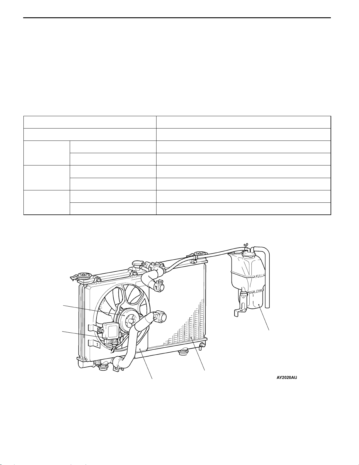
COOLING SYSTEM
The cooling system is a water-cooled pressurized, forced circulation type which offers the following features.
D To improve the reliability of cavitation at a high engine speed and to increase the amount of engine
coolant, output control system in which a thermostat is installed at the outlet of engine coolant from
the engine to the radiator has been adopted.
D To improve the engine cooling performance and save weight, a plastic tank and an aluminium radiator
fins have been introduced.
D The speed of electric cooling fan is optimally controlled by a radiator fan controller and the engine-ECU
according to driving conditions so that the fan operating noise is minimized and the fuel efficiency
is improved.
SPECIFICATIONS
Items Specifications
Cooling method Water-cooled pressurized, forced circulation with electrical fan
Radiator Type Pressurized corrugate type
Performance kJ/h 216,700
Water pump Type Impeller of centrifugal type
Drive method Drive belt
Thermostat Type Wax pellet type with jiggle valve
Valve open temperature _C 80 ± 1.5
CONSTRUCTION DIAGRAM
Radiator fan
motor
Radiator fan
controller
Reserve tank
Shroud
Radiator
Page 25
1-6
ENGINE - Intake and Exhaust
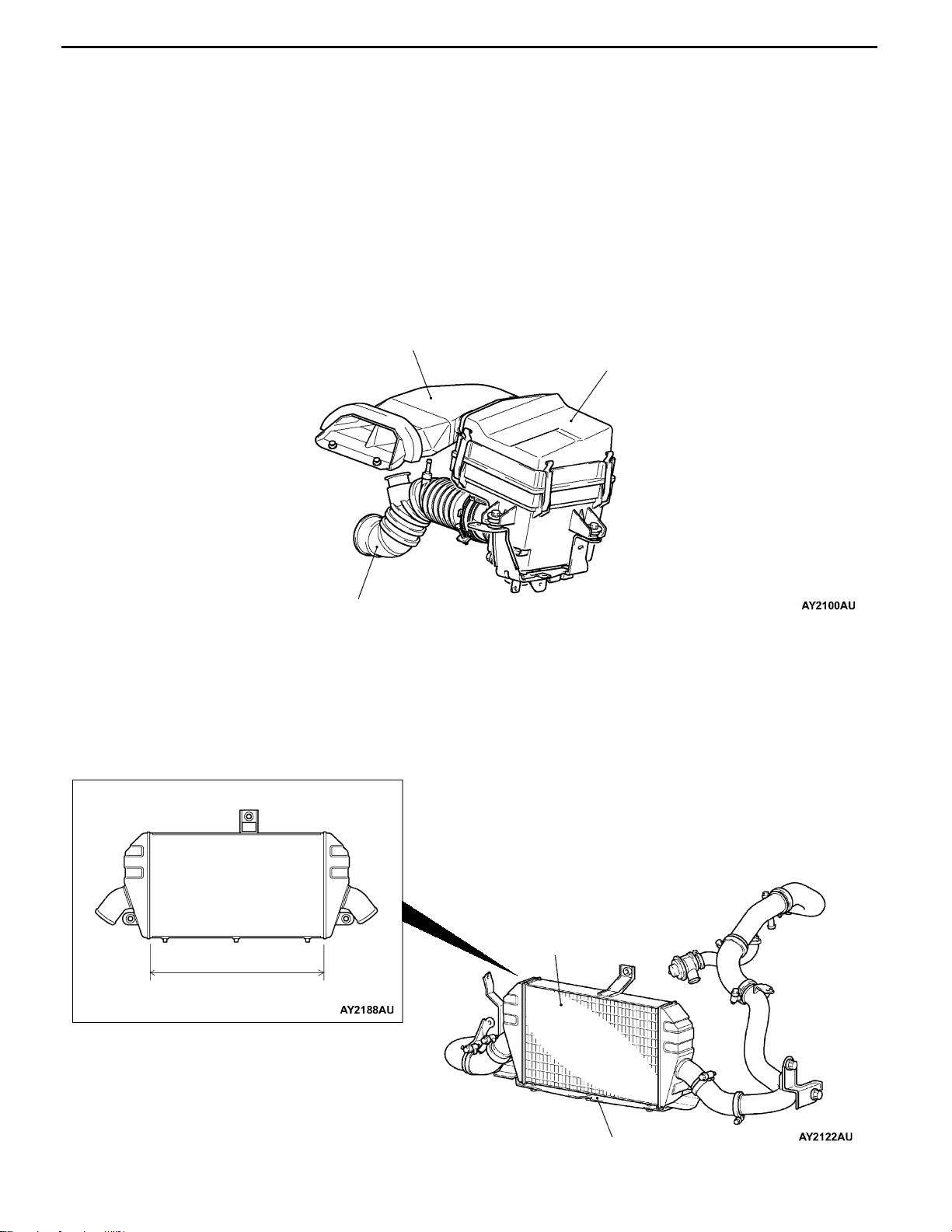
INTAKE AND EXHAUST
AIR INTAKE SYSTEM
AIR DUCT, AIR CLEANER
D By introducing fresh cool air from the top of the radiator efficiently, the engine performance has been
enhanced and intake air noise has been reduced.
D Burnable used paper mixed with plastic materials have been adopted in consideration for reduction
of industrial wastes and protection of global environment.
AIR INTAKE HOSE
Unleaded rubber materials have been adopted for air intake hose in consideration for protection of global
environment.
CONSTRUCTION DIAGRAM
Air duct
Air cleaner assembly
Air intake hose
INTER COOLER
By mounting an air cooled intercooler to reduce the intake air temperature after boosting, engine output
has been improved. The features of the air cooled intercooler are as follows.
D Large intercooler (Core size: 289.5×490×65 mm)
D Air guides are mounted to the bottom of the intercooler.
CONSTRUCTION DIAGRAM
Inter cooler assembly
490 mm
Air guide
Page 26
ENGINE - Intake and Exhaust
1-7
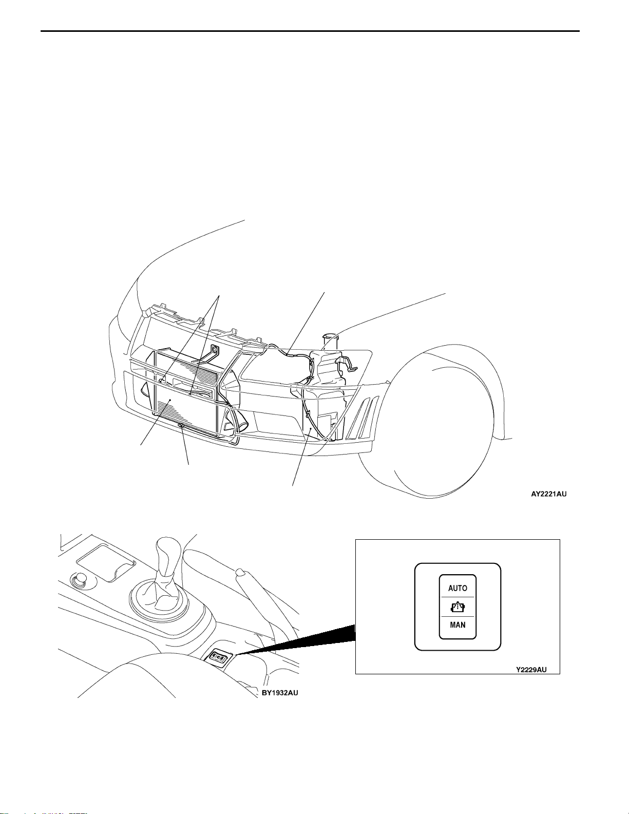
INTER COOLER WATER SPRAY
To complement the intercooler efficiency in ranges where the cooling efficiency of the air cooled intercooler
is insufficient, and attain high performance in various operating environments, a system which cools by
spraying water from a special washer tank for the intercooler to the front of the intercooler has been
adopted.
The features of the intercooler water spray system is as follows.
D Sprays water when the water spray switch on the floor console is operated.
D Adopts a system which enables switching between the auto mode which automatically sprays water
at the optimum operating conditions by signals from the ECU according to the engine state, and
the manual mode which is operated by the driver.
D Three water spray nozzles are located at optimum positions to enhance the intercooler efficiency.
CONSTRUCTION DIAGRAM
<Water Spray Nozzle/Water Spray Hose/Washer Tank>
Inter cooler
<Water Spray Switch>
Water spray nozzle
Water spray nozzle
Water spray hose
Washer tank
Water spray switch
Page 27
1-8
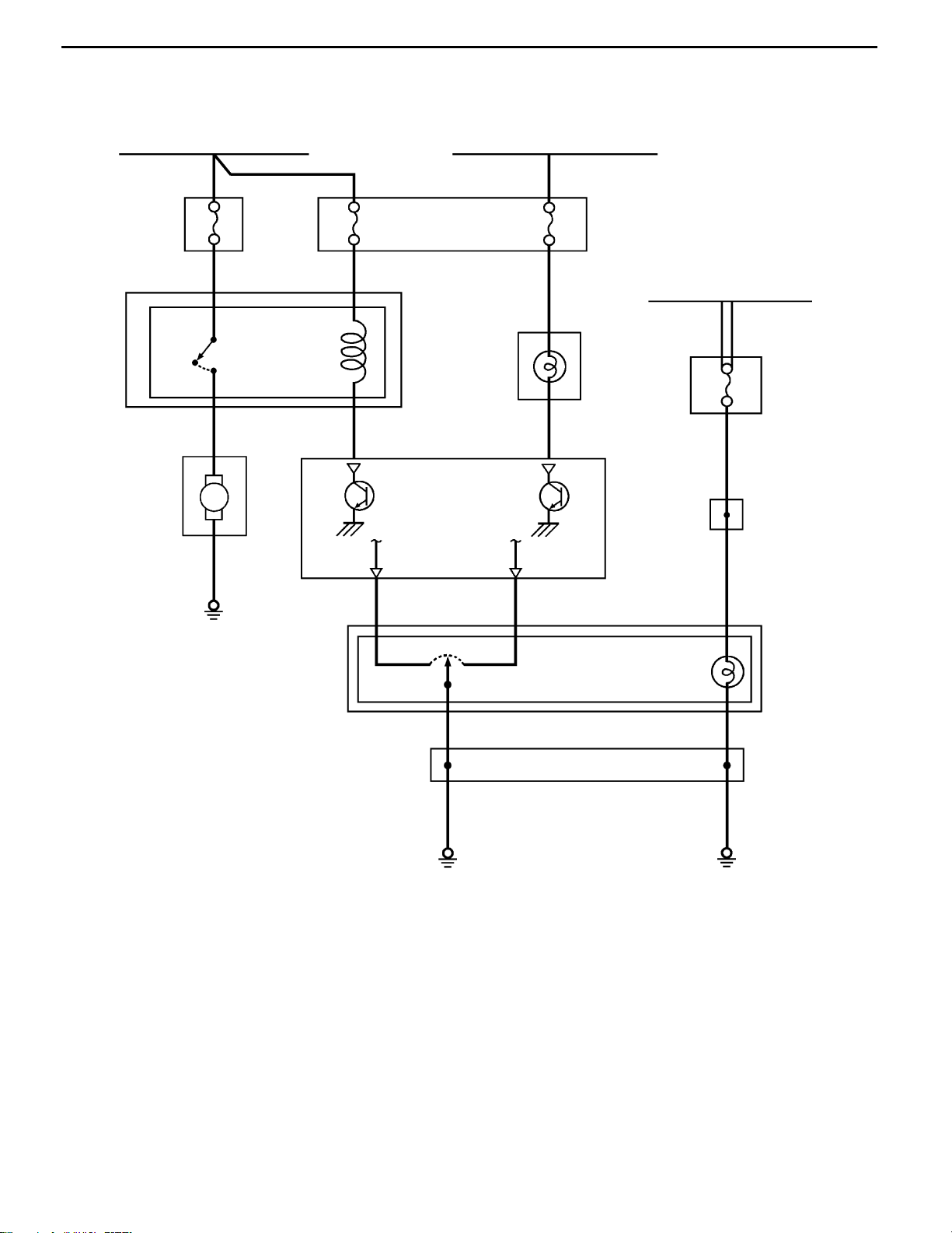
SYSTEM DIAGRAM
ENGINE - Intake and Exhaust
Ignition switch (IG2)
Fuse
20A
J/B
Water spray
motor
Water spray relay
OFF ON
M
7.5A
J/B
Engine-ECU
Ignition switch (IG1)
7.5A
Combination
meter
Front-ECU
(Tail lamp relay)
Fuse
7.5A
J/C
MANUAL AUTO
Water spray switch
J/C
Page 28
Exhaust fitting
Exhaust fitting bracket
ENGINE - Exhaust System
Exhaust manifold
heat protector
1-9
EXHAUST SYSTEM
EXHAUST FITTING BRACKET
An exhaust fitting bracket has been added in order to provide
greater rigidity.
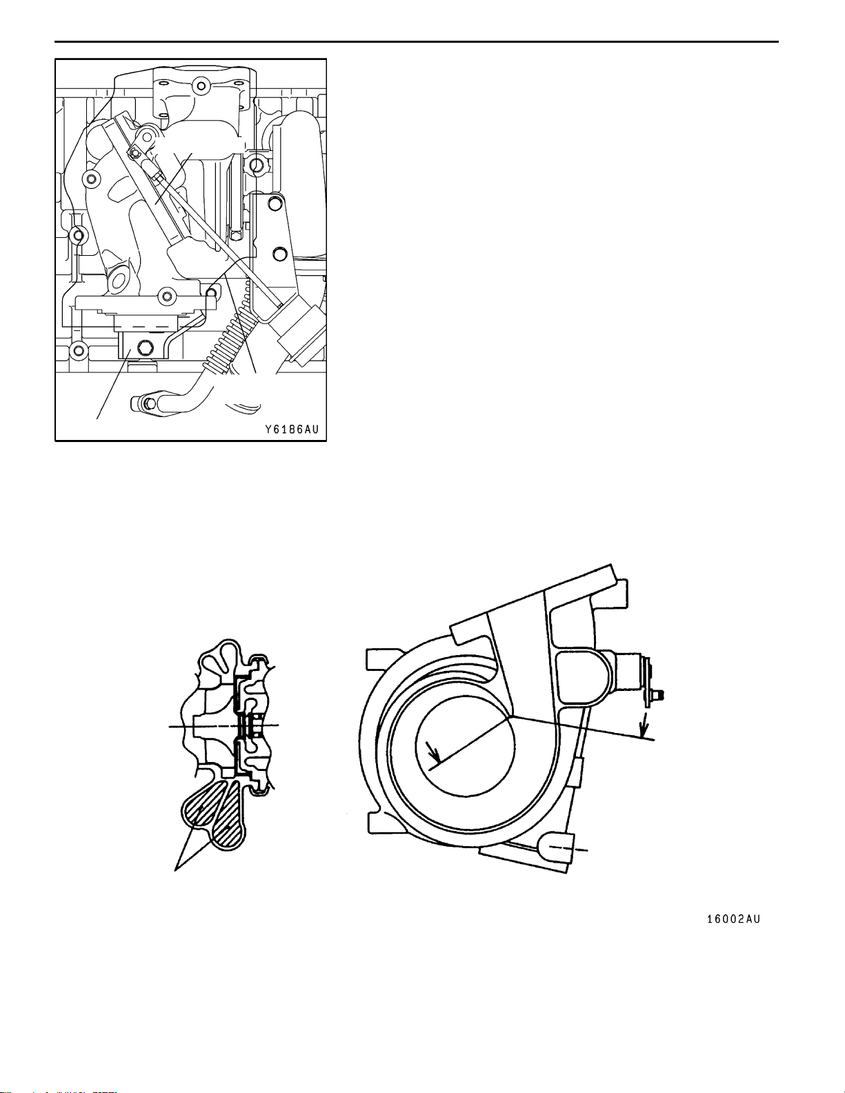
TURBOCHARGER
The turbocharger type TD05HR-16G6-9.8T and TD05HRA-16G6-9.8T have been adopted.
Compared to previous types of turbocharger, these new types have a smaller turbine housing nozzle
area which improves response at medium to low speeds.
A
A
Nozzle area
Section A - A
Page 29
1-10
ENGINE - Intake and Exhaust
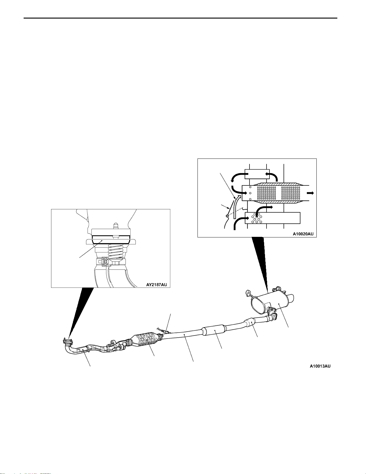
EXHAUST PIPE AND MUFFLER
Exhaust pipe consisting of 3 separation system: front exhaust pipe, center exhaust pipe, and exhaust
main muffler, has the following features:
D The adoption of a seal ring has reduced vibrations during idling and driving noise.
D A main muffler incorporating a back pressure variable valve is adopted.
D Straight layout of exhaust piping has reduced vibration and exhaust pressure in exhaust system.
D The adoption of hanger rubber with lower spring constant and the decreased number of hangers
have reduced vibration in exhaust piping.
D The adoption of all stainless exhaust piping has enhanced resistance to corrosion and heat.
D Installation of thermal insulating cover and materials on front pipe has improved emission control
performance.
CONSTRUCTION DIAGRAM
When valve
is open
Seal ring
Front exhaust pipe
Back
pressure
variable
valve
Flow of exhaust gas
Oxygen sensor
Main muffler
Pre-muffler (sub)
Pre-muffler
Catalytic converter
Center exhaust pipe
Page 30
ENGINE - Fuel System
Fuel
tank
L48Fuel
Electri
Fuel
294
j
1-11
FUEL SYSTEM
The fuel system consists of parts such as electromagnetic-type fuel injectors, a delivery pipe and a fuel
pressure regulator. In addition, a fuel pressure control solenoid valve has been provided in order to maintain
idling stability after the engine is re-started when it is hot. This system is basically the same as the
previous system used in the 4G63-DOHC-Turbocharger engine for the EVOLUTION-VI.
SPECIFICATIONS
Items Specification
capacity
pumptype
Fuel filter type Cartridge (filter-paper type)
Fuel return system Fuel pressure regulator return
pressure regulator controlpressurekPa
Injectors
Evaporative emission control system Canister type
Type Electromagnetic
Quantity 4
c
CONSTRUCTION DIAGRAM
Fuel pump resistor
Injector resistor
Delivery pipe
Fuel pressure regulator
Injector
Fuel tank
Evaporative canister
Fuel cut-off valve assembly
Fuel pump and gauge assembly
Pipe and gauge assembly
Fuel pump relay
Page 31

1-12
ENGINE - Fuel System
FUEL TANK
A steel fuel tank is located under the floor of the
rear seats to provide increased safety and increase
the amount of luggage compartment space.
D The fuel tank has been equipped with a valve
assembly which incorporates a fuel cut-off valve
to prevent fuel from leaking out in the event
of a collision for adjusting the pressure inside
the fuel tank.
CONSTRUCTION DIAGRAM
Fuel high-pressure hose
Suction hose
D For better serviceability, the fuel tank has been
coupled with the main line by a one-touch joint
method, not the conventional double flare nut
method.
Fuel pump and gauge assembly
Pipe and gauge assembly
Fuel high-pressure hose
Fuel cut-off valve assembly
Fuel tank
Page 32

ENGINE - Control System
1-13
CONTROL SYSTEM
The control system is based on the system for 4G63-DOHC-Tubocharger which has been installed in
the EVOLUTION-VI, with the following improvements added.
Improvements/Additions Remarks
Adoption of compact throttle position sensor D Smaller size and light weight
D Higher resistance to vibration
D Idle position switch disused
D Basically the same as that used in the SPACE
WAGON
Adoption of compact stepper motor for idle speed control
servo
Adoption of PWM (pulse width modulation) method of
radiator fan motor control
Adoption of dual oxygen sensor D Higher reliability of air fuel ratio control
Adoption of intercooler water spray control D Improved intercooler cooling efficiency
D Improved ignition performance
D Basically the same as that used in the LANCER
D Reduced fuel consumption
D Reduced fan noise
D Basically the same as that used in the LANCER
D Basically the same as that used in the GALANT
Page 33

1-14
SYSTEM BLOCK DIAGRAM
ENGINE - Control System
Air flow sensor
Intake air temperature sensor
Barometric pressure sensor
Engine coolant temperature sensor
Throttle position sensor
A/C switch
A/C load signal
Camshaft position sensor
Crank angle sensor
Vehicle speed sensor
Power steering fluid pressure switch
Detonation sensor
Intercooler water spray (auto)
Engine-ECU
Fuel injection control
Idle speed control
Ignition timing control
Engine control relay control
Fuel pump relay control
A/C relay control
Fan motor control
(radiator)
Fan relay control
(A/C condenser)
Alternator control
Air flow sensor filter reset control
Fuel pressure control
Turbochanger control
No.1 injector
No.2 injector
No.3 injector
No.4 injector
Idle speed control servo
(stepper motor)
No.1, No.4 ignition coil
No.2, No.3 ignition coil
Engine control relay
Fuel pump relay 2
Fuel pump relay 3
Tachometer
A/C relay
Fan controller
(radiator)
Fan motor relay (HI, LOW)
(A/C condenser)
Alternator G terminal
Air flow sensor
Fuel pressure control solenoid valve
Waste gate solenoid valve
Intercooler water spray (manual)
Oxygen sensor (front)
Oxygen sensor (rear)
Ignition switch-IG
Ignition switch-ST
Alternator FR terminal
Power supply
Diagnosis control terminal
Secondary air control
Intercooler water spray control
Engine warning lamp control
Oxygen sensor heater control
EGR control
Purge control
Diagnosis output
RAM data transmission
Secondary air control solenoid valve
Intercooler water spray relay
Intercooler water spray lamp
Engine warning lamp
(check engine lamp)
Oxygen sensor heater (front)
Oxygen sensor heater (rear)
EGR control solenoid valve
Purge control solenoid valve
Diagnosis output terminal
Diagnosis output terminal
(for MUT-II)
Page 34

ENGINE - Control System
CONTROL SYSTEM DIAGRAM
1-15
L1 Oxygen sensor (front)
L2 Oxygen sensor (rear)
L3 Air flow sensor
L4 Intake air temperature sensor
L5 Throttle position sensor
L6 Camshaft position sensor
L7 Crank angle sensor
L8 Barometric pressure sensor
L9 Engine coolant temperature sensor
L10 Detonation sensor
D Power supply
D Ignition switch-IG
D Ignition switch-ST
D Vehicle speed sensor
D A/C switch
D A/C load signal
D Power steering fluid pressure switch
D Alternator FR terminal
Check
l7 Secondary
air control
solenoid
valve
valve
Canister
By-pass
valve
Engine-ECU
From
fuel tank
L5 Throttle
position
sensor
l1 Injector
l2 Idle speed control servo
l3 Fuel pressure control solenoid valve
l4 Waste gate solenoid valve
l5 EGR control solenoid valve
l6 Purge control solenoid valve
l7 Secondary air control solenoid valve
D Engine control relay
D Fuel pump relay 2, 3
D A/C relay
D Ignition coil
D Fan controller
D Condenser fan relay (HI)
D Condenser fan relay (LOW)
D Engine warning lamp
D Diagnosis output
D Alternator G terminal
l2 Idle
speed
control
servo
Vacuum
tank
L8 Barometric
L3 Air flow
Air
inlet
Secondary
air valve
pressure
sensor
sensor
L4 Intake air
temperature
sensor
l6 Purge
control
solenoid
valve
L1 Oxygen
sensor
(front)
l4 Waste gate
solenoid valve
l3 Fuel pressure
Waste gate
actuator
control
solenoid valve
Fuel
pressure
regurator
To fuel tank
L6 Camshaft
PCV valve
l5 EGR control
solenoid valve
l1 Injector
position sensor
From
fuel pump
EGR
valve
L9 Engine coolant
temperature sensor
L7 Crank angle sensor
L10 Detonation sensor
L2 Oxygen sensor (rear)
Three-way
catalytic converter
Page 35

1-16
ENGINE - Control System
LIST OF COMPONENT FUNCTIONS
Name Function
ECU Engine-ECU Uses the signals input from the various sensors to control operation of
actuators in accordance with the driving conditions.
Sensors Ignition switch-IG Detects the ON/OFF position of the ignition switch. When this signal
is input to the engine-ECU, power is supplied to components such as
the injectors, air flow sensor, idle speed control servo and crank angle
sensor.
Ignition switch-ST Detects whether the engine is cranking. The engine-ECU controls the
fuel injection, throttle valve opening angle and ignition timing to the
appropriate settings based on this signal.
Air flow sensor Detects the amount of intake air (volumetric capacity) by means of a
Karman vortex meter. The engine-ECU controls the basic injector drive
time based on this signal and on the engine speed.
Barometric pressure sensor Detects the barometric pressure by means of a semiconductor
diffusion-type pressure sensor. The engine-ECU detects the vehicle’s
altitude based on this signal, and uses this to correct the fuel injection
amount so that the optimum air/fuel mixture ratio is obtained for that
altitude.
Oxygen sensor Detects the concentration of oxygen in the exhaust gas by means of
zirconia and platinum electrodes. The engine-ECU judges whether the
air/fuel mixture ratio is at the optimum theoretical ratio based on this
concentration.
Intake air temperature sensor Detects the temperature of the intake air by means of a thermistor. The
engine-ECU corrects the fuel injection amount to the correct amount
corresponding to the intake air temperature based on the voltage
output from this sensor.
Engine coolant temperature
sensor
Throttle position sensor Detects the throttle valve opening angle by means of a potentiometer.
Vehicle speed sensor Detects the vehicle speed by means of a magnetic rheostatic element.
Camshaft position sensor Detects the No. 1 cylinder compression top dead centre position by
Crank angle sensor Detects the crank angle by means of a hall element. The engine-ECU
Detects the temperature of the engine coolant by means of a
thermistor. The engine-ECU detects how warm the engine is based on
the signal from this sensor, and uses this to control the fuel injection
amount, idle speed and ignition timing.
The engine-ECU controls the throttle valve and also determines the
optimum fuel injection for the vehicle’s degree of acceleration based
on the voltage output from this sensor.
means of a hall element.
controls the injectors based on the signal from this sensor.
Alternator FR terminal Detects the energising duty ratio of the alternator field coil.
Power steering fluid pressure
switch
A/C switch Detects the ON/OFF condition of the A/C.
Detects whether there is a power steering load present by means of a
contact switch.
Page 36

ENGINE - Control System
Name Function
Sensors A/C load signal Inputs the compressor drive state (low load/high load) to the
engine-ECU. The engine-ECU controls the A/C idle-up revolution
speed using this signal.
1-17
Intercooler water spray switch
(automatic)
Intercooler water spray switch
(manual)
Diagnosis control terminal Notifies the engine-ECU that the MUT-II has been connected to the
Actuators Engine control relay Turns the engine-ECU power circuit on and off.
Injector Drives the fuel injection by means of drive signals from the
Ignition coil
(integrated power transistor)
Idle speed control servo The throttle valve bypass air amount during idling and deceleration is
Fuel pump relay 1 Supplies power to the fuel pump when the ignition switch is at the ON
Fuel pump relay 2 Controls the supply of power to the fuel pump in accordance with the
Sprays water when certain driving conditions are satisfied.
Sprays water while the switch is being pressed by the driver.
diagnosis connector, and enables communication between the MUT-II
and the engine-ECU.
engine-ECU.
Interrupts the ignition coil primary current in accordance with the
ignition signals from the engine-ECU, in order to generate a high
voltage for ignition.
controlled with the signal from the engine-ECU.
position.
signal from the engine-ECU.
Fuel pump relay 3 Controls the supply of power to the fuel pump when driving at low loads
and when driving at high loads, in accordance with the signal from the
engine-ECU.
Fan controller Controls the smooth operation of the radiator fan in accordance with
the signal from the engine-ECU.
Condenser fan relay (HI) Controls the condenser fan operation (high speed) in accordance with
the signal from the engine-ECU.
Condenser fan relay (LOW) Controls the condenser fan operation (low speed) in accordance with
the signal from the engine-ECU.
Intercooler water spray relay Controls the driving of the intercooler spray motor in accordance with
the signal from the engine-ECU.
Waste gate solenoid valve Controls the supercharging pressure which acts on the waste gate
actuator in accordance with the signal from the engine-ECU.
Purge control solenoid valve Controls the purge air flow amount which is introduced into the surge
tank in accordance with the signal from the engine-ECU.
EGR control solenoid valve Controls the negative pressure which operates the EGR valve in
accordance with the signal from the engine-ECU.
Secondary air control solenoid
valve
Controls the pressure which is introduced into the secondary air valve
in accordance with the signal from the engine-ECU.
Fuel pressure control solenoid
valve
Controls the fuel pressure in accordance with the signal from the
engine-ECU.
Page 37

1-18
Name Function
Actuators Alternator G terminal Controls the current generated by the alternator in accordance with the
A/C relay Controls the A/C compressor operation.
ENGINE - Control System
signal from the engine-ECU.
Engine warning lamp
(check engine lamp)
Intercooler water spray lamp Illuminates when the intercooler is being sprayed in accordance with
Illuminates when a sensor malfunction is detected to warn the driver
of the problem.
the signal from the engine-ECU.
Page 38

ENGINE - Control System
1-19
FUEL INJECTION CONTROL
The fuel injection control system is basically the same as the control system for the 4G63-DOHC-Turbocharger
engine installed in the Evolution-VI.
SYSTEM CONFIGURATION DIAGRAM
Air flow sensor
Barometric pressure sensor
Intake air temperature sensor
Engine coolant temperature sensor
Throttle position sensor
Camshaft position sensor
Crank angle sensor
Ignition switch-ST
Oxygen sensor
Vehicle speed sensor
Detonation sensor
To fuel
tank
Fuelpressure
regulator
Fuel pressure control
solenoid valve
Engine-ECU
From
fuel
pump
Injector
IDLE SPEED CONTROL
The idle speed control system is basically the same as the control system for the 4G63-DOHC-Turbocharger
engine installed in the Evolution-VI.
SYSTEM CONFIGURATION DIAGRAM
Air flow sensor
Barometric pressure sensor
Bimetal type limiter
To intake
manifold
Idle speed control servo
(Stepper motor)
From air
cleaner
Speed adjusting screw
Engine-ECU
Intake air temperature sensor
Engine coolant temperature sensor
Throttle position sensor
Crank angle sensor
A/C switch
A/C load signal
Vehicle speed sensor
Power steering fluid pressure switch
Alternator FR terminal
Ignition switch-IG
Ignition switch-ST
Diagnosis control terminal
Page 39

1-20
ENGINE - Control System
IGNITION TIMING AND DISTRIBUTION CONTROL
The ignition timing and distribution control system is basically the same as the control system for the
4G63- DOHC-Turbocharger engine installed in the Evolution-VI.
SYSTEM CONFIGURATION DIAGRAM
Air flow sensor
Barometric pressure sensor
Intake air temperature sensor
Engine coolant temperature sensor
Camshaft position sensor
Crank angle sensor
Detonation sensor
Ignition switch-ST
Vehicle speed sensor
EngineECU
To tachometer
Ignition switch
Ignition
coil A
Spark plug
Cylinder No. 4 1 32
Battery
Ignition
coil B
RADIATOR FAN MOTOR CONTROL
The radiator fan motor control system is basically the same as the control system for 4G6-MPI engine
installed in the GALANT.
POWER SUPPLY AND A/C CONDENSER FAN RELAY CONTROL, OXYGEN
SENSOR HEATER CONTROL, AIR FLOW SENSOR FILTER RESET CONTROL,
ALTERNATOR CONTROL, FUEL PRESSURE CONTROL, SUPERCHARGING
PRESSURE CONTROL, SECONDARY AIR CONTROL
These control systems are basically the same as those for 4G63-DOHC-Turbocharger engine installed
in the EVOLUTION-VI.
Page 40

ENGINE - Control System
1-21
FUEL PUMP RELAY CONTROL
D The fuel injection amount is controlled by the fuel pump relay 3 in order to reduce the amount of
return fuel when the engine is running at low speeds and fuel consumption is low, and also to reduce
noise.
Battery
Ignition switch
Fuel pump relay 1
Engine-ECU
Fuel
pump
relay 3
Fuel pump relay 2
Fuel pump resistor
To fuel pump
Page 41

1-22
ENGINE - Control System
EGR CONTROL AND PURGE CONTROL
Refer to the EMISSION CONTROL SYSTEM.
DIAGNOSIS SYSTEM
The engine-ECU is prvided with the following functions to make system inspection easier.
D Engine warning lamp control
D Diagnosis function
D Service data output
D Actuator test
NOTE
Refer to the Workshop Manual for details on each item.
Page 42

ENGINE - Emission Control System
1-23
EMISSION CONTROL SYSTEM
The following improvements in the control details have been made to the system, which is basically
the same as the previous system used in the 4G63-DOHC-Turbocharger engine for the EVOLUTION-VI.
D An electronically-controlled EGR system utilizing an EGR control solenoid valve has been adopted.
D An electronically-controlled purge control system utilizing purge control solenoid valve has been adopted.
System Remarks
Evaporative emission control system Electronic control type
(Duty cycle type purge control solenoid valve)
Exaust gas recirculation (EGR) system Electronic control type
(Duty cycle type EGR control solenoid valve)
EMISSION CONTROL SYSTEM DIAGRAM
From
fuel
Check
valve
Canister
tank
Air
inlet
Purge
control
solenoid
valve
Oxygen
sensor
(front)
Fuel pressure
control
solenoid valve
Fuel
pressure
regurator
To fuel
tank
PCV valve
EGR control
solenoid valve
Injector
From fuel
pump
EGR
valve
Oxygen sensor (rear)
Three-way
catalytic converter
Page 43

1-24
ENGINE - Mount
MOUNT
The inertia axial system based on the past achievements in COLT/LANCER has been adopted for the
engine mount system.
D Longitudinal installation type of cylindrical liquid-filled engine mount has been adopted for reduction
of idle vibration and improvement of ride feeling.
D The liquid-filled mount system has been adopted for transmission mount to improve ride feeling by
optimizing the insulator.
D Installation of roll mount in the upper area has reduced engine rolling. Furthermore, enlargement
of insulator diameter has reduced idle vibration.
CONSTRUCTION DIAGRAM
<Engine mount/Transmission mount>
Engine mount
Transmission mount
Page 44

ENGINE - MountENGINE - Mount
<Engine roll stopper/Crossmember/Centermember : L.H. drive vehicles>
Rear roll mount bracket
Rear roll rod assembly
Front roll mount bracket
Front roll stopper
1-25
Rear roll rod bracket
Crossmember
Crossmember bar
Centermember
<Engine roll stopper/Crossmember/Centermember : R.H. drive vehicles>
Rear roll mount bracket
Front roll mount bracket
Front roll stopper
Rear roll stopper
Crossmember
Centermember
Crossmember bar
Page 45

1-26
ENGINE - Accelerator System
ACCELERATOR SYSTEM
The accelerator system is a cable and suspended
pedal combination.
Plastic bushing and rubber damper have been attached to the end of the accelerator cable, to pre-
CONSTRUCTION DIAGRAM
Accelerator
cable
Accelerator arm
vent noise and vibration when the cable and accelerator arm contact.
Plastic bushing
Rubber
dumper
<L.H. drive vehicles>
Accelerator cable
Accelerator
pedal bracket
Accelerator arm
<R.H. drive vehicles>
Accelerator cable
Accelerator
pedal bracket
Accelerator arm
Page 46

POWER TRAIN
CONTENTS
2-1
CLUTCH 2................................
Specifications 2.............................
MANUAL TRANSMISSION 3................
Specifications 3.............................
Sectional View 4............................
4WD System 8.............................
Power Train 9..............................
Transmission Control 11.....................
ACTIVE CENTER DIFFERENTIAL (ACD)
AND ACTIVE YAW CONTROL (AYC)
Description of Structure and Operations 16....
System Structure 16.........................
Oil Pressure Unit 18.........................
Electronic Control System 20.................
PROPELLER SHAFT 27....................
FRONT AXLE 28..........................
REAR AXLE 29............................
DIFFERENTIAL 30.........................
12........
DIFFERENTIAL MOUNT 33.................
Page 47

2-2
POWER TRAIN - Clutch
CLUTCH
SPECIFICATIONS
Items Specifications
Engine model 4G63-DOHC-Intercooler Turbocharger
Clutch disc type Dry single plate type
Clutch disc facing diameter O.D.×I.D. mm 240×160
Clutch cover type Diaphragm spring pull type
Clutch cover set load N 9,320 ± 750
Control system Hydraulic type
Release cylinder I.D. mm 20.64
Master cylinder I.D. mm 15.87
Clutch fluid Brake fluid DOT 3 or DOT 4
CLUTCH CONTROL CONFIGURATION
<L.H.drive vehicles>
Clutch hose
Clutch pipe
Clutch master cylinder
Clutch release
cylinger
<R.H.drive vehicles>
Master cylinder member assemblyReservoir hose
Clutch pedal
Reservoir hose
Clutch master cylinder
Master cylinder member assembly
Clutch pipe
Clutch pipe
Clutch release cylinger
Clutch pedal
Clutch hose
Page 48

POWER TRAIN - Manual Transmission
2-3
MANUAL TRANSMISSION
The manual transmission is a W5M5 transmission. This transmission incorporates the following changes
from the F5M4 type transmission mounted to GALANT.
D With the incorporation of 4WD, the center differential has been positioned at the front differential
of the 2WD, and the front differential has been positioned inside the transfer.
D The kinetic performance has been improved by setting a helical gear LSD for the front differential.
<RS, RS II: Option>
D With the adoption of the active center differential (ACD), an hydraulic multi plate clutch has been
adopted for the transfer limited slip differential. <RS, RS II: Option> (Refer to P.2-17 for details
of the hydraulic multi plate clutch.)
SPECIFICATIONS
Item Specifications
Classification RS, RS II RS, RS II (Super cross gear specifications)
Transmission type W5M51
Engine type 4G63-DOHC-T/C
Transmission type 5 steps forward, 1 step reverce, always in contact)
Gear ratio
Final deceleration ratio 4.529 ←
Helical gear LSD (Front differential) No Yes
Transfer
1st 2.785 ←
2nd 1.950 ←
3rd 1.407 1.444
4th 1.031 1.096
5th 0.720 0.825
Reverse 3.416 ←
Deceleration ratio 3.307 ←
Limited slip differential VCU or hydraulic multi
plate clutch (ACD)
←
Page 49

2-4
SECTIONAL VIEW
W5M51 <Vehicle with VCU>
POWER TRAIN - Manual Transmission
12
4
5
3
6
7
8
9
15
19
18
17
16
14
20
1. 4th gear
2. 3rd - 4th synchronizer
3. 3rd gear
4. Transmission case
5. Clutch housing
6. Clutch release bearing retainer
7. Input shaft
8. Output shaft
9. Front differential
10. Viscous coupling unit (VCU)
10
11
13
12
11. Transfer cover
12. Hypoid pinion
13. Center differential
14. 1st gear
15. 1st - 2nd synchronizer
16. 2nd gear
17. 5th gear
18. 5th - reverse synchronizer
19. Reverse gear
20. Reverse idler gear
Page 50

W5M51 <Vehicle with ACD>
POWER TRAIN - Manual Transmission
2-5
4
1
2
3
5
6
7
8
9
21
20
19
18
17
16
22
1. 4th gear
2. 3rd - 4th synchronizer
3. 3rd gear
4. Transmission case
5. Clutch housing
6. Clutch release bearing retainer
7. Input shaft
8. Output shaft
9. Front differential
10. Clutch housing
11. Transfer cover
15
10
11
12
13
14
12. Piston
13. Transfer hydraulic case
14. Hypoid pinion
15. Center differential
16. 1st gear
17. 1st - 2nd synchronizer
18. 2nd gear
19. 5th gear
20. 5th - reverse synchronizer
21. Reverse gear
22. Reverse idler gear
Page 51

2-6
POWER TRAIN - Manual Transmission
W5M51 <Vehicle with Helical Gear LSD and VCU>
4
1
2
3
5
6
7
8
9
19
18
17
16
15
14
20
1. 4th gear
2. 3rd - 4th sychronizer
3. 3rd gear
4. Transmission case
5. Clutch housing
6. Clutch release bearing retainer
7. Input shaft
8. Output shaft
9. Front differential (Helical gear LSD)
10. Viscous coupling unit (VCU)
13
10
11
12
11. Transfer cover
12. Hypoid pinion
13. Center differential
14. 1st gear
15. 1st - 2nd sychronizer
16. 2nd gear
17. 5th gear
18. 5th - reverse synchronizer
19. Reverse gear
20. Reverse idler gear
Page 52

POWER TRAIN - Manual Transmission
W5M51 <Vehicle with Helical Gear LSD and ACD>
2-7
4
1
2
3
5
6
7
8
9
17
21
181920
16
22
1. 4th gear
2. 3rd - 4th sychronizer
3. 3rd gear
4. Transmission case
5. Clutch housing
6. Clutch release bearing retainer
7. Input shaft
8. Output shaft
9. Front differential (Helical gear LSD)
10. Clutch housing
11. Transfer cover
15
10
11
12
13
14
12. Piston
13. Transfer hydraulic case
14. Hypoid pinion
15. Center differential
16. 1st gear
17. 1st - 2nd sychronizer
18. 2nd gear
19. 5th gear
20. 5th - reverse synchronizer
21. Reverse gear
22. Reverse idler gear
Page 53

2-8
POWER TRAIN - Manual Transmission
4WD SYSTEM
The 4WD system is a center differential full-time 4WD with limited slip differential.
The center differential has been positioned at the front differential of the 2WD transmission, and the
front differential has been positioned inside the transfer. The limited slip differential of the center differential
has been positioned at the back of the front differential in the transfer.
For the limited slip differential of the center differential, a viscous coupling unit (VCU) or active center
differential (ACD) has been adopted.
Engine
Transfer
Center differential
Limited slip
differential
Front differential
Rear differential
Page 54

POWER TRAIN - Manual Transmission
2-9
POWER TRAIN
Helical Gear LSD
The helical gear LSD is composed of four long pinions, four short pinions, three thrust washers, side
gears A and B, and cases A and B.
The long pinions are in contact with the side gear B and short pinions, while the short pinions are in
contact with the side gear A and long pinions.
Case B
Short pinion
Thrust washer
Side gear B
Long pinion
Side gear A
Case A
Power Flow
Operations in forward driving
During forward driving, as the differential case and and drive shaft rotate at the same speed, they
rotate at the assembly without the inside of the differential moving.
The driving force at this time will be transmitted as follows.
Differential case
Short pinion
→ Long and short pinions → Side gears A and B → Drive shaft
Driving power
Differential case
Side gear B
Side gear A
Long pinion
Page 55

2-10
POWER TRAIN - Manual Transmission
Operations during differential (when there is rotational difference between the left and right
wheels)
When the frictional coefficient of the left and right wheels are more or less equal, and a slight rotational
difference occurs at the left and right wheels (normal turning), rotational difference will also occur
between side gears A and B. In this case, while the long pinions and short pinions mutually rotate
in the reverse direction, the vicinity of side gears A and B revolves and absorbs the speed difference.
In this way, like normal differential, the high speed side accelerates for the revolved amount in respect
to the revolution speed of the differential case,while the low speed side rotates in the decelerated
state and performs differential.
Differential case
Revolution
Autorotation
High speed side
Side gear A
Autorotation
Driving power
Side gear B
Low speed
side
Long pinion
Short pinion
Operations during Limited Slip Differential
When the loads of the left and right wheels become unbalanced due to changes in road surface
conditions and sudden turning, the driving torque of side gears A and B will differ.
As mentioned earlier, because side gears A and B are in contact via the respective long and short
pinions, the gears influence each other, resulting in contact reaction force (F and f) between the
long pinion and side gear B, and the short pinion and side gear A.
The separating force (Ft and ft) in the axial direction of the contact reaction force causes side gears
A and B to be pushed and extended. From this force, side gears A and B are pushed against the
thrust washer (case) and friction occurs.
The separating force (Fr and f r) in the radial direction of the contact reaction force causes the long
pinion and short pinion to be pushed against the differential case (cases A and B). This force generates
a large friction between the long pinion, short pinion, and differential case (cases A and B).
Friction also occurs on the gear with the generation of contact reaction force (F and f) of the four
gears (pinions).
These frictional forces cause the generation of frictional torque at each section according to the
size of the driving torque input to the differential case, and the generation of limited slip differential
torque proportionate to the input torque.
Page 56

POWER TRAIN - Manual Transmission
2-11
Driving power
Torque
High speed
side
Long pinion
Differential case
Short pinion
TRANSMISSION CONTROL
D The shift lever construction adopted the
spherical rotary shaft fulcrum type to assure
a non-rickety.
D The base bracket material adopted a synthetic
resin for the weight reduction.
Forward direction
Thrust washer
FFr
Ft
Low speed
side
Side gear A
f
fr
ft
Thrust washer
Side gear B
D The shift and select cable securing portions
have been elastically supported to reduce
contained sound.
D A mass-filled shift knob has been adopted to
minimize the binding touch at the time of a
shift.
CONSTRUCTION DIAGRAM
Select cable
Shift lever assembly
Shift cable
Base bracket
Page 57

2-12
POWER TRAIN - ACD and AYC
ACTIVE CENTER DIFFERENTIAL (ACD) AND ACTIVE YAW CONTROL (AYC)
The LANCER EVOLUTION-VII adopts the newly developed active center differential (ACD).
The driving performance of the ACD has been improved by varying the center differential drive by electronic
control.
The yaw moment is directly controlled by the active yaw control (AYC) adopted from EVOLUTION-V
onwards to improve the turning performance.
By combining and integratedly controlling these two systems, the driving performance has been further
improved.
RS, RS II
ACD Option
ACD and AYC Option
OUTLINE OF CONTROL
The following effects are obtained by equipping the ACD or ACD and AYC.
State of vehicle ACD AYC Integrated control effects
1. During deceleration
(Before
corners)
2. First half of
turning
(Corner entrance)
3. Latter half
of turning
(Corner
exit)
Similar to the direct engagement
4WD by increasing the center
differential during sharp deceleration to improve stability in deceleration.
The center differential restriction is
reduced according to the steering
angle and operation speed to set
the center differential as close as
possible to the free state and
improve turning performance.
The center differential restriction is
enhanced according to the amount
the acceleration is stepped to set
similar effects as the direct engagement 4WD and improve the acceleration performance.
[When decelerated during
turning]
The driving power is moved to
the inside turning wheel to
reduce the tack in.
The driving power is moved to
the outside turning wheel
according to the steering
angle and operation speed to
improve the turning performance.
The driving power is moved to
the outside turning wheel
according to the amount the
acceleration is stepped to
decrease the acceleration
understeer and improve turning performance.
Stability against various
external influences such as
poor road conditions and
driver operations have been
improved.
The response to steering
operations (brisk movement) is improved as much
as possible.
Two elements (acceleration
and turning) have been
improved simultaneously.
2. First half of turning
AYC: Turning
1. During deceleration
AYC: Tack in deceleration
(During deceleration when turning)
ACD: Free
ACD: Direct
engagement
3. Latter half of turning
AYC: Under steer deceleration
ACD: Direct engagement
Page 58

COMPONENT VIEW
ACD mode indicator lamp
POWER TRAIN - ACD and AYC
Parking brake switch
Steering
wheel sensor
2-13
AYC torque transfer
differential
Throttle position sensor (TPS)
ABS-ECU
ACD transfer
Engine-ECU
4WD-ECU
Longitudinal
G sensor
ACD mode switch
Stop lamp switch
Reserve tank
Hydraulic unit
assembly
Lateral G sensor
Wheel speed sensor
Wheel speed sensor
Page 59

2-14
p
y
LIST OF MAIN COMPONENTS
POWER TRAIN - ACD and AYC
Components
ACD transfer Controls the transmission torque of the hydraulic multi plate clutch by the
4WD-ECU Processes information of various sensors and switches, calculates the hydraulic
Engine-ECU Sends the engine idling state to the 4WD-ECU.
ABS-ECU Outputs the ABS monitor signal to the 4WD-ECU.
Throttle position sensor (TPS) Sends the throttle valve opening angle to the 4WD-ECU.
Longitudinal G sensor Sends the acceleration in the front and rear directions of the vehicle to the
Lateral G sensor Sends the acceleration along the side of the vehicle to the 4WD-ECU.
Steering wheel sensor Sends the steering angle and neutral position to the 4WD-ECU.
Wheel speed sensor Sends the wheel speed to the 4WD-ECU.
Stop lamp switch Sends the brake operating state to the 4WD-ECU.
Parking brake switch Sends the operating state of the parking brake to the 4WD-ECU.
ACD mode indicator lamp
ACD mode switch Switches the ACD control mode (TARMAC, GRAVEL, SNOW).
Hydraulic
unit
Electric pump relay Supplies the power to the electric pump.
AYC torque transfer differential Controls the transmission torque of the left and right clutches according to the
Pressure sensor Sends the pressure of the accumulator to the 4WD-ECU.
Electric pump Generates oil pressure for clutch operations.
Directional valve Controls whether to supply the oil pressure to the left or right AYC clutch.
Proportional valve
<ACD>
Proportional valve
<AYC>
Outline of function
hydraulic unit, and adjusts the center differential.
multi plate clutch transmission torque and amount of AYC torque movement and
direction, and controls the hydraulic unit on the basis of them.
4WD-ECU.
Displays the ACD control mode (TARMAC, GRAVEL, SNOW).
Lights the all mode lamp during fail. (Lights for about1.5 seconds after the ignition
switch is turned ON)
Controls hydraulic supplied to hydraulic multi plate clutch of the ACD.
Controls oil pressure supplied to the AYC clutch.
oil pressure from the hydraulic unit, and adjusts the left and right driving power
difference of the rear wheels.
Page 60

OUTLINE OF ACD AND AYC
POWER TRAIN - ACD and AYC
2-15
<ACD and AYC
Equipped Vehicle>
ABSECU
ABS monitor signal
Wheel speed sensor <FL>
Wheel speed sensor <RL>
Wheel speed sensor <RR>
Wheel speed sensor <FR>
Wheel speed sensor <FL>*
Wheel speed sensor <RL>*
Wheel speed sensor <RR>*
Wheel speed sensor <FR>*
Longitudinal G sensor
Lateral G sensor
Stop lamp
Steering wheel sensor
Pressure sensor
Throttle position sensor
ECU power supply
1
1
1
1
4WD-ECU
Idling information
ACD mode switch
Parking brake switch
ACD mode indicator lamp
Diagnostic connector
Direction valve*
2
Proportional valve*2(AYC)
Proportional valve (ACD)
Engine-ECU
Wheel speed
sensor <FR>
ACD transfer
Hydraulic
multi
plate clutch
Center
differential
Wheel speed sensor <FL>
NOTE
1
1.
*
indicates equipped with only ACD.
2
*
indicates equipped with ACD and AYC.
2.
Steering wheel sensor
Stop lamp switch
Wheel speed sensor <RR>
Lateral G sensor
Longitudinal G sensor
Wheel speed sensor <RL>
Right clutch*
Left clutch*
Electric
pump
Reservoir
tank relay
Pressure
sensor
2
2
Proportional
valve
(ACD)
Accumulator
Electric
Proportional
2
valve*
(AYC)
Direction al
2
valve*
pump
Hydraulic unit
AYC torque transfer
differential *
2
Page 61

2-16
POWER TRAIN - ACD and AYC
DESCRIPTION OF STRUCTURE AND OPERATIONS
The ACD system adopts a transfer limited slip differential as the hydraulic multi plate clutch, and electronically
controls it using sensors, 4WD-ECU, and hydraulic unit.
NOTE
Refer to P.2-30 for details on the AYC structure and operations.
SYSTEM STRUCTURE
AYC torque transfer
ACD transfer
Hydraulic unit
(Electric pump with
accumulator)
Engine
4WD-ECU
differential
T/M
Steering wheel sensor
TPS
Wheel speed sensor
Longitudinal G sensor
Lateral G sensor
Sensors
Page 62

POWER TRAIN - ACD and AYC
TRANSFER LIMITED SLIP DIFFERENTIAL
2-17
During acceleration and deceleration, the piston is moved in the right direction according to the oil pressure
from the hydraulic unit to connect the hydraulic multi plate clutch (friction plate and disc) and set the
center differential to the direct engagement state as much as possible. This improves the acceleration
performance and stability during deceleration.
During turning, the oil pressure from the hydraulic unit stops, the piston operates in the left direction
to release the hydraulic multi plate clutch and free the center differential to improve the turning performance.
If the parking brake is pulled while driving at a vehicle speed above 5 km/h, the hydraulic multi plate
clutch will also be released and the center differential set as close as possible to the free state.
Hydraulic unit
assembly
ACD transfer
A
A
Section A - A
Transfer hydraulic case
Piston
Thrust bearing
Hydraulic multi plate clutch
(Friction plate and disk)
<During acceleration
and deceleration>
<During turning>
Page 63

2-18
POWER TRAIN - ACD and AYC
HYDRAULIC UNIT
The hydreaulic unit is composed of the accumulator (electric pump, pressure sensor, accumulator) and
pressure controller (proportional valve, directional valve).
The pressure accumulator intermittently operates the pump, and accumulates the control pressure required
in the accumulator.
The pressure controller operates the proportional valve and directional valve, and supplies the appropriate
oil pressure to the ACD transfer or AYC torque transfer differential according to the signals from the
4WD-ECU.
SPECIFICATIONS
Specifications Specifications
Electric pump Trochoidal type
Operating oil ATF SP III
Proportional valve Current proportional control type
Directional valve 3 position electromagnetic switching method
TPS
Stop lamp switch
Wheel speed sensor
Longitudinal G sensor
Lateral G sensor
Steering wheel sensor
Engine-ECU
ABS-ECU
ACD mode switch
Parking brake switch
Electronic control system
Oil pressure control system
4WD-ECU
Electric pump relay
ACD mode
indicator lamp
Hydraulic unit assembly
Pressure sensor
Electric
pump
Proportional
valve (AYC)
Directional
valve
Left
AYC clutch
Accumulator
Proportional
valve (ACD)
Right
ACD transfer
Hydraulic multi
plate clutch
Proportional
valve <ACD>
Proportional
valve <AYC>
Proportional valve
Supplies the oil pressure required for ACD or AYC control
according to the instructions of the 4WD-ECU.
Page 64

Proportional
valve (OFF)
POWER TRAIN - ACD and AYC
From electric pump
2-19
When the proportional valve is OFF, the oil pressure from
the electric pump will be cut off by the proportional valve.
For this reason, oil pressure will be supplied to the ACD
or AYC and each system will be set into the non-operating
state.
Proportional
valve (ON)
To ACD hydraulic multi plate
clutch or AYC directional valve
Directional
valve (OFF)
From electric pump
Return
From proportional
valve <AYC>
When the proportional valve turns ON, the proportional valve
opens, and the oil pressure from the electric pump will be
supplied to the ACD hydraulic multi plate clutch or AYC
directional valve.
Directional valve
Supplies the oil pressure required for controlling the AYC
clutch according to the instructions of the 4WD-ECU.
Directional
valve
When the directional valve is OFF, the oil pressure from the
proportional valve <AYC> will be cut off by the directional
valve. For this reason, the clutch will set into the non-operating
state without oil pressure supplied to each clutch of the AYC.
Directional valve
(Right side: ON)
To clutch
<Left side>
From proportional valve
<AYC>
To clutch
<Left side>
To clutch
<Right side>
To clutch
<Right side>
When oil pressure supply signal for the AYC clutch <Right
side> is sent to the directional valve from the 4WD-ECU,
the directional valve will move to the right. As a result, the
oil pressure from the proportional valve <AYC> will be supplied
to the AYC clutch <Right side>.
If the oil pressure supply signal to the AYC clutch <Left side>
is sent to the directional valve, the directional valve will move
to the left.
Page 65

2-20
POWER TRAIN - ACD and AYC
ELECTRONIC CONTROL SYSTEM
THROTTLE POSITION SENSOR
For detecting the throttle valve opening angle. Also used as throttle position sensor for engine control.
LONGITUDINAL G SENSOR/LATERAL G SENSOR
The longitudinal G sensor are sensors detecting the acceleration in the longitudinal directions of the
vehicle, and are basically the same as those used conventionally.
The lateral G sensor is used for detecting the acceleration along the sides of the vehicle by changing
the installing direction by 90° . The same sensor as the longitudinal G sensor is used.
G-sensor output characteristics
Parking brake lever
Lateral G sensor
Longitudinal
G sensor
Output voltage (V)
4.0
3.5
2.5
1.5
1.0
01.0
Acceleration speed
(G)
1.01.5 1.5
Deceleration speed
(G)
STEERING WHEEL SENSOR
The steering wheel sensor is installed at the steering column, and is used to output steer angles to
the 4WD-ECU as signals.
It is composed of the slit plate which rotates according to the movements of the handle and a three-set
photointerruptor. The slit plate and photointerruptor have a sealed integrated structure to prevent the
invasion of foreign particles as well as misoperations by external light. To detect malfunctions of the
sensor output circuit, it is equipped with a zener diode for detecting disconnections parallel to the
phototransistor.
The ECU calculates the steering angle by reading the signals of the steering wheel sensor after every
certain period of time and calculating the total of the ST-1 signal and ST-2 signal.
The steering angle is obtained by taking the neutral position (ST-N output is L center) as 0° , and if
there are changes, the steering angle is added with 2° for right and - 2° for left. The output of the
photointerruptor becomes L (low) when light passes through and H (high) when obstructed.
Page 66

POWER TRAIN - ACD and AYC
Steering wheel sensor
Slit
Slit plate
Output waveform of each sensor
N (Neutral point)
V
ST-1
ST-2
ST-N
H
L
V
H
4° 4°
L
V
H
L
4°4°
11°
2-21
2°
θ
θ
θ
Slit plate
Photointerruptor
(ST-2)
<Front>
Wheel speed sensor
<Rear>
Wheel speed sensor
Photointerruptor
(ST-1)
Neutral position
detection slit
Zener diode
for disconnec-
Photointerruptor
(ST-N)
Light-emitting diode
Photo-transistor
tion detection
WHEEL SPEED SENSOR
Sensor for detecting each wheel speed. It is the same as
that conventionally adopted for the ABS. For vehicle with
ACD and AYC, the wheel speed sensor signal
waveform-shaped by the ABS-ECU is input to the 4WD-ECU.
Page 67

2-22
ACD mode switch
POWER TRAIN - ACD and AYC
ACD MODE SWITCH
When the ACD mode switch is pressed, the mode switches
to TARMAC, GRAVEL, or SNOW.
ACD mode TARMAC GRAVEL SNOW
Good condition roads
Dry paved
roads
Wet roads,
gravel roads
Snowy roads
ACD mode indicator lamp
Pressure
sensor
Hydraulic unit
assembly
ACD MODE INDICATOR LAMP
For about 1.5 seconds after the Ignition switch is turned ON,
all ACD mode indicator lamps will light up. When the ACD
mode switch is pressed, each mode (TARMAC, GRAVEL,
SNOW) will light up alternately.
When the ACD or AYC malfunctions, all mode indicators will
light up (until the ignition switch goes OFF*).
NOTE
*: When the vehicle is determined as having returned to normal
according to the malfunction, the lamps will also be returned
to their normal states.
PRESSURE SENSOR
Detects the pressure of the accumulator, and sends the signal
to the 4WD-ECU. The 4WD-ECU controls the operations of
the electric pump on the basis of this signal.
ELECTRIC PUMP RELAY
Supplies power to the electric pump according to the signal
from the 4WD-ECU.
4WD-ECU
Door check
Electric pump relay
4WD-ECU
Determines the driving state, vehicle state, and road state
according to the inputs of each sensor, idling information
from the engine-ECU, and ABS monitor signal from the
ABS-ECU to control the hydraulic unit.
The 4WD-ECU also has a diagnosis function which lights
up all the ACD mode indicator lamps during malfunctions.
Page 68

POWER TRAIN - ACD and AYC
p
The terminals of the 4WD-ECU are arranged as follows.
2-23
NOTE
1. *
2. *
1. Proportional valve <ACD>
2. -
3. Proportional valve <AYC>*
1
4. -
5. -
6. Wheel speed sensor <FL>
7. Wheel speed sensor <RR>
8. Wheel speed sensor <RL>
9. Wheel speed sensor <FR>
10. Pressure sensor earth
11. Lateral G sensor
12. -
13. 4WD-ECU power supply
14. Directional valve <Right>*
15. Directional valve <Left>*
1
1
16. Electric pump relay power supply
17. -
18. -
19. Wheel speed sensor earth <FL>*
20. Wheel speed sensor earth <RR>*
21. Wheel speed sensor earth <RL>*
22. Wheel speed sensor earth <FR>*
2
2
2
2
23. Longitudinal G sensor
24. Longitudinal G sensor and lateral
G sensor earth *
1
indicates that the terminal is omitted if only ACD is equipped.
2
indicates that the terminal is added if only ACD is equipped.
2
25. -
26. ECU earth
31. ECU backup power supply
32. Pressure sensor
33. Steering wheel sensor <ST-1>
34. Steering wheel sensor <ST-2>
35. Diagnosis data input/output
36. Idle switch
37. Parking brake switch
38. Stop lamp switch
39. TPS
40. ACD mode indicator lamp <TARMAC>
41. -
42. ECU earth
43. Pressure sensor power supply
44. Steering wheel sensor <ST-N>
45. -
46. Diagnostic control
47. ACD mode switch
48. -
49. ABS monitor *
50. Earth*
2
1
51. ACD mode indicator lamp <SNOW>
52. ACD mode indicator lamp <GRAVEL>
DIAGNOSIS ITEMS
Code
No.
12 Power supply voltage
13 Fail save relay f Open-circuit or short-circuit of ECU equipped fail save relay
21 Wheel speed sensor
22 Wheel speed sensor <FL> f Open-circuit or short-circuit of wheel speed sensor <FL>
23 Wheel speed sensor
24 Wheel speed sensor
25
26
31 Steering wheel sensor f Steering wheel sensor <ST-N,ST-1,ST-2> system
Diagnosis Item Mode indica-
tor lamp (f: all
lit, – : normally
displayed)
f Open-circuit, short-circuit of power supply voltage system, or
(Valve power supply)
f Open-circuit or short-circuit of wheel speed sensor <FR>
<FR>
f Open-circuit or short-circuit of wheel speed sensor <RR>
<RR>
f Open-circuit or short-circuit of wheel speed sensor <RL>
<RL>
Wheel speed sensor
- Equipped with step-bore tire
f Wheel speed sensor defect
Main diagnosis details
drop in voltage
system
system
system
system
opened or short-circuit
Page 69

2-24
g
g
pp
y
POWER TRAIN - ACD and AYC
Code
No.
32
33
34 Steering wheel sensor
41
42 f Short-circuit of TPS system
45
46 f Earth open-circuit of pressure sensor system
47 f Power supply defect of pressure sensor system
51
52
56
57 f Lateral G sensor defect
61 Stop lamp switch f Open circuit of stop lamp switch system
62 ACD mode switch f ACD mode switch is stuck
63 Parking brake switch f Short-circuit of parking brake switch or it has not been returned
65 ABS f Open-circuit of ABS monitor system or malfunction of ABS
71 Proportional valve <AYC> f Open-circuit or short-circuit of proportional valve <AYC>
72 Directional valve <Right> f Open-circuit or short-circuit of directional valve <right> system
73 Directional valve <Left> f Open-circuit or short-circuit of directional valve <left> system
74 Proportional valve <ACD> f Open-circuit or short-circuit of proportional valve <ACD>
81
82
84 AYC control f AYC control defect
85 ACD control f ACD control defect
Diagnosis Item
Steering wheel sensor
<ST-N>
<ST-1, ST-2>
TPS
Pressure sensor
Longitudinal G sensor
Lateral G sensor
Electric pump relay
tor lamp (f: all
lit, – : normally
displayed)
f Steering wheel sensor <ST-N> system short-circuit
f Fixing of steering wheel sensor <ST-N> system
f Short-circuit or fixing of output of steering wheel sensor <ST-1,
f Open-circuit or grounding of TPS system
f Open-circuit or short-circuit of pressure sensor system
f Open-circuit and short-circuit of longitudinal G sensor system
f Longitudinal G sensor defect
f Open-circuit or short-circuit of lateral G sensor
f Open-circuit or short-circuit of electric pump relay system
f Electric pump malfunction or pressure sensor defect
Main diagnosis detailsMode indica-
ST-2> system
to designated position
system
system
Page 70

POWER TRAIN - ACD and AYC
2-25
SERVICE DATA
Item No. Item Unit
01 Wheel speed sensor <FR> km/h (Displayed for every 1 km/h)
02 Wheel speed sensor <FL> km/h (Displayed for every 1 km/h)
03 Wheel speed sensor <RR> km/h (Displayed for every 1 km/h)
04 Wheel speed sensor <RL> km/h (Displayed for every 1 km/h)
05 Wheel speed sensor <FR> (0.2 km/h) km/h (Displayed for every 0.2 km/h)
06 Wheel speed sensor <FL> (0.2 km/h) km/h (Displayed for every 0.2 km/h)
07 Wheel speed sensor <RR> (0.2 km/h) km/h (Displayed for every 0.2 km/h)
08 Wheel speed sensor <RL> (0.2 km/h) km/h (Displayed for every 0.2 km/h)
09 Vehicle speed km/h
10 Battery voltage V
11 Proportional valve current<ACD> mA
12 Proportional valve current <AYC> mA
13 TPS voltage mV
14 Longitudinal G sensor voltage V
15 Lateral G sensor voltage V
16 Steering angle deg
17 Steering angle speed deg/s
18 Pressure sensor MPa
19 Pressure sensor power supply V
20 Valve power supply V
21 Steering wheel sensor voltage <ST-1> V
22 Steering wheel sensor voltage <ST-2> V
23 Steering wheel sensor voltage <ST-N> V
51 Idle switch ON/OFF
52 Steering wheel sensor <ST-N> ON/OFF
53 Steering wheel sensor <ST-1> ON/OFF
54 Steering wheel sensor <ST-2> ON/OFF
55 Steering wheel sensor learning <ST-N> ON/OFF
56 Stop lamp switch ON/OFF
57 Motor monitor ON/OFF
58 Oil pressure state HIGH/LOW
59 Directional valve <Right> ON/OFF
60 Directional valve <Left> ON/OFF
61 ABS monitor ON/OFF
62 Parking brake switch ON/OFF
63 ACD mode switch ON/OFF
Page 71

2-26
ACTUATOR TEST
POWER TRAIN - ACD and AYC
Item No. Content Drive Specifications Driving
time
01 Bleeding
<ACD>
02 Bleeding
<AYC>
03 Oil amount
check
04 Electric pump
drive
05 ACD clutch op-
eration check
06 AYC clutch op-
eration check
<Left side>
07 AYC clutch op-
eration check
<Right side>
08 Control OFF Turns OFF the electric
Outputs current to the
proportional valve according to the steering angle.
Outputs current to the
proportional valve according to the steering angle to
operate the direction
valve.
Operates the directional
valve to the left and right.
Operates the electric
pump for 5 seconds.
Operates the proportional
valve <ACD> to supply
maximum oil pressure to
the multi plate clutch.
Operates the directional
valve, and supplies maximum oil pressure to the
left side clutch.
Operates the directional
valve, and supplies maximum oil pressure to the
right side clutch.
pump relay, and ACD
control and AYC control.
5 minutes Check that no air is discharged from the
5 minutes Check that no air is discharged from the
20 seconds
To end of
operations
1 minute With the vehicle lifted up, check the
1 minute With the vehicle lifted up, check the
1 minute With the vehicle lifted up, check the
- Check the difference between control ON
Check
bleeder screw installed on the ACD
transfer.
bleeder screw installed on the AYC torque
transfer differential.
Check the oil amount of the reservoir tank.
Check the operating state from the
operation sound of the electric pump.
operating state according to the speed
difference between the front and rear
wheels.
operating state according to the speed
difference between the front and rear
wheels.
operating state from the speed difference
between the left and right rear wheels.
and OFF in actual driving.
Page 72

POWER TRAIN - Propeller ShaftPOWER TRAIN - Propeller Shaft
ft
di
joint
PROPELLER SHAFT
3 way split 4-joint type propeller shaft with center bearing is adopted.
SPECIFICATIONS
Item Vehicles without AYC Vehicles with AYC
2-27
Propeller
sha
Universal
Type 3 way split 4-joint type propeller shaft
Length × Outside
ameter mm
Type No.1 Cross type (caulking method)
Bearing Lubricationless type needle roller bearing
Journal diameter mm 16.3
Front 608.5 × 65
Center 551 × 65
Rear 750.5 × 65 768.5 × 65
No.2 Cross type (caulking method)
No.3 Constant velocity type (LJ)
No.4 Cross type (caulking method)
NOTE
The propeller shaft length indicates the length between the centre points of each joint.
CONSTRUCTION DIAGRAM
Center bearing
Rear propeller shaft
Sleeve yoke
Front propeller shaft
No.1 joint
No.2 joint
Center propeller shaft
No.3 joint
(LJ)
No.4 joint
Page 73

2-28
g
FRONT AXLE
DRIVETRAIN - Front Axle
The front axle consists of front hubs, knuckles,
wheel bearings and drive shafts, and it has the
following features.
D The wheel bearing is unit bearing (Double-row
angular contact ball bearing) which is integrated
with hub.
D The drive shaft incorporates B.J.-T.J. type
constant velocity joints with high transmission
efficiency and low vibration and noise.
D ABS rotors for detecting the wheel speeds are
press-fitted to the B.J. outer wheels in vehicles
with ACD or ABS.
NOTE
1. B.J.: Birfield Joint
2. T.J.: Tripod Joint
SPECIFICATIONS
Item Specifications
Wheel
bearings
Drive
shaft
Wheel bearing type Hub unitbearing (Double-row angular
contact ball bearing)
Bearing (outside diameter) mm 87*
Joint type
Shaft length*2× Shaft diameter mm
Outside B.J.
Inside T.J.
Left 350 × 26
Right 427 × 26
1
NOTE
1
: The wheel bearing is integrated with hub,only the outer diameter is shown.
*
2
: The shaft length indicates the length between the center points of each joint.
*
STRUCTURAL DIAGRAM
Strut assembly
T.J.(L.H.)
Knuckle
Front hub
B.J.
Output shaft
Drive shaft
Output shaft
T. J .
T.J.(R.H.)
Wheel bearing
Page 74

DRIVETRAIN - Rear Axle
g
REAR AXLE
The rear axle consists of rear hubs, wheel bearings,
drive shafts, and rear differentialand, it has the
following features.
D The wheel bearing is a unit bearing (double-row
angular contact ball bearing).
NOTE
1. B.J.: Birfield Joint
2. T.J.: Tripod Joint
SPECIFICATIONS
Item Vehicles without AYC Vehicles with AYC
D The drive shaft incorporates B.J.-T.J. type
constant velocity joints with high transmission
efficiency and low vibration and noise.
D ABS rotors for detecting the wheel speeds are
press-fitted to the B.J. outer wheels in vehicles
with ACD or ABS.
2-29
Wheel
bearings
Drive
shaft
Wheel bearing type Unit bearing (Double-row angular contact ball
bearing)
Bearing (outside diameter × inside diameter) mm 78 × 40
Joint type
Shaft length*1× Shaft diameter
mm
Outside B.J.
Inside T.J.
Left 483 × 25 426 × 25
Right 573 × 25 446 × 25
NOTE
1
: The shaft length indicates the length between the center points of each joint.
*
STRUCTURAL DIAGRAM
Differential carrier
T. J .
Oil seal
B.J.
Rear hub
Drive shaft
Page 75

2-30
gyp(
yp
g
(
DRIVETRAIN - Differential
DIFFERENTIAL
Mechanical type Limited Slip Differential <Vehicles without AYC> or Torque transfer differential <Vehicles
with AYC> is adopted. About the structure of AYC, refer to P.2-3, manual transmission.
MECHANICAL LIMITED SLIP DIFFERENTIAL
SPECIFICATIONS
Item Mechanical LSD
Reduction gear type Hypoid gear
Reduction ratio 3.312
Differential gear type (Type ×
number of gears)
Number of teeth
Bearings (Outside diameter ×
Inside diameter) mm
Side gear Straight bevel gear × 2
Pinion gear Straight bevel gear × 4
Drive gear 43
Drive pinion 13
Side gear 14
Pinion gear 10
Side 72.0 × 35.0
Front 62.0 × 25.0
Rear 72.0 × 35.0
CONSTRUCTION DIAGRAM
<Mechanical LSD>
Differential carrier
Page 76

DRIVETRAIN - Differential
2-31
TORQUE TRANSFER DIFFERENTIAL
The torque transfer differential consists of differential mechanism,acceleration/decelation gear and two
pairs of wet multi-plate clutch. The hipoid gear oil is used to lublicate differential part, ATF-SP III is used
to lublicate torque movement part (acceleration/decelation gear and clutch).
L.H. clutch
Differential
mechanism
R.H. clutch
Wet multi-plate clutch
Reductiongear
Input gear
Acceleration/decelation gear
Overdrive gear
DIFFERENTIAL MECHANISM
When the vehicle turns, admits the revolution difference between inner race and outer race.
ACCELERATION/DECELATION GEAR
Have the revolution speed of right and left wet multi-plate clutch to accelerate or decelate as oposed
to the revolution speed of right wheel.
WET MULTI-PLATE CLUTCH
Have the torque to move from high speed wheel to low speed wheel.
L.H. clutch operate: decelation geer have the torque to move R.H. wheel to L.H. wheel.
R.H. clutch operate: accelelation geer have the torque to move L.H. wheel to R.H. wheel.
The movement of torque is dependence on pushing force of the clutch.
Page 77

2-32
DRIVETRAIN - Differential
High
speed
side
Pushing
force
Differential
case
Decelation
gear
Turning
direction
Driving
power
(large)
Yaw
moment
Driving
power
moves
L.H.
Clutch
Low
speed
side
Pushing
force
R.H.
Clutch
Acceleration
gear
L.H.clutch
Driving
power
(small)
TORQUE TRANSFER DIFFERENTIAL MECHANISM
When high speed clutch is pushed, the driving power always
moves from high speed side to low speed side, and controls
the driving power with the aid of the property which the
movement of driving power is proportional to the pushing
force of clutch.
In torque transfer differential, acceleration/decelation gear
always engages, and towerd to input speed from the
differential case, L.H. clutch engaging decelation gear is
revolutes in low speed, R.H. clutch engaging accelelation
gear is revolutes in high speed.
In the other hand, the housing side of R.H/L.H. clutch is
integlated to rear R.H. axle, if R.H. or L.H. clutch is opelated,
the driving power can be moved to right or left.
THE FLOW OF DRIVING POWER
(1) L.H.CLUTCH OPERATE
In order to boost the driving power of L.H. wheel, when
L.H.clutch is operated,a part of the driving power of R.H.
wheel flows to the differential case, the driving power
of L.H. wheel is boosted.
The result of this, the yaw moment occures in a right
to the vehicle.
Driving
power
(small)
Yaw
moment
R.H.
clutch
Turning
direction
Driving
power
(large)
(2) R.H.CLUTCH OPERATE
In order to boost the driving power of R.H. wheel,when
R.H.clutch is operated, a part of the driving power of
L.H. wheel flows to the differential case, the driving power
of R.H. wheel is boosted.
The result of this, the yaw moment occures in a left to
the vehicle.
Page 78

DRIVETRAIN - Differential Mount
DIFFERENTIAL MOUNT
2-33
The front of differential carrier is suported with the
differential support member via the differential
mount bracket with insulator,and the rear is
suported with the differential support arm.
<Mechanical LSD>
<Mechanical LSD>
Toe control bar
Differential support member
Differential mount bracket
The front of torque transfer differential is supported
with the differential support member with insulator
via the differential mount bracket,and the rear is
supported with the differential mount bracket and
the differential support arm. <AYC>
Differential support arm
<AYC>
Differential support member
Differential mount
bracket (R.H.)
Insulator
Differential support arm
Differential mount bracket
Insulator
Differential mount
bracket (L.H.)
Page 79

NOTES
Page 80

DRIVE-CONTROL
COMPONENTS
CONTENTS
3-1
SUSPENSION 2.........................
Features 2................................
FRONT SUSPENSION 2..................
Features 2................................
Construction Diagram 3....................
Specifications 3...........................
Lower Arm 4..............................
Stabilizer Bar 5............................
REAR SUSPENSION 5...................
Features 5................................
Construction Diagram 5....................
Specifications 6...........................
WHEEL AND TYRE 7.....................
Features 7................................
Specifications 7...........................
POWER STEERING 8....................
Features 8................................
Specifications 8...........................
Construction Diagram 9....................
Steering Wheel 10..........................
Steering Shaft and Column 10................
Oil Pump 12...............................
Power Steering Fluid Cooler Tube 12..........
Steering Gear 13...........................
BRAKES 14..............................
Features 14................................
Construction Diagram 15....................
SERVICE BRAKES 16.....................
Specifications 16...........................
Master Cylinder 17..........................
Brake Booster 17...........................
Disc Brakes 18.............................
Brake Line 19..............................
4-WHEEL ANTI-SKID BRAKING SYSTEM
(4ABS) 20................................
Features 20................................
Specifications 20...........................
Construction Diagram 21....................
System Configuration Diagram 22.............
ABS Electrical Circuit Diagram 23.............
Sensors 24................................
Actuators 25...............................
ABS-ECU 26...............................
System Operation 27........................
PARKING BRAKE 27......................
Features 27................................
Construction Diagram 27....................
Page 81

3-2
DRIVE-CONTROL COMPONENTS - Suspension/Front Suspension
SUSPENSION
The suspension which has been adjusted to new
body dimension with the optimal tuning has improved its cornering ability.
FEATURES
High Steering
Stability
Enhanced Riding
Comfort
Reduced road
noise
1. Suspension geometry optimized by linearisation of toe change, etc.
2. Wider tread
3. Optimized the roll center height
4. Increased the suspension stroke of the compressed side
5. Increased the lateral rigidity equipped with crossmember bars and flatted
crossmember
6. Damping forces of front struts and rear shock absorbers as well as
their coil springs’ characteristics optimized
7. Optimized suspension bushings
1. Increased the suspension stroke of the compressed side
2. Damping forces of front struts and rear shock absorbers as well as
their coil springs’ characteristics optimized
3. Spring characteristics of bump rubber optimized
4. Characteristics of suspension bushings optimized
1. Increased the volume of stabilizer bushings
2. Adoption of two mounting bolts to the stabilizer bracket
A McPherson strut-type suspension has been used
at the front, and a multi-link suspension has been
used at the rear.
FRONT SUSPENSION
FEATURES
A McPherson strut independent suspension-type
suspension has been adopted as the front
suspension. It has improved its limitation of
capacity as well as securing the sufficient lateral
rigidity and rolling rigidity as a high performance
vehicle.
D With widened tread and optimized roll center
height, the cornering performance from initial
responce to limited performance has been
improved.
D Adopted the two- stage selectable structuare
of camber angle according to driving mode like
EVOLUTION-VI.
D Stabilized the vehicle behavior during cornering
by lowering the installation position of the
steering gear box with linear toe change.
D Increased the horizontal strength, improved the
steering feeling and the rigidness at the time
of cornering by making the cross member flat
and connecting two reinforced bars
(crossmember bar) at the installation part of
the both right and left lower arms.
D Improved the cornering limitation with improved
adhesion at the time of rolling by increasing
bump strokes.
D Achieved the weight reduction being equipped
with aluminium lower arm like EVOLUTION-VI.
D Improved reliability by making the size of
mounting bolts larger at the front and rear
bushing installation parts of lower arm.
D Improved the stroke feeling by replacing the
rear bushings of the lower arm with the pillow
ball bushing with rubber.
D Restricted the useless movement of lower arm
equipped with stopper rubber at the front and
rear bushing mounting parts of the lower arm.
D Improved the reliability and steering feeling by
reducing friction as well as making the ball size
of lower arm ball joint larger.
D Improved the camber rigidity by adopting an
inverted strut like EVOLUTION-VI.
D Improved the steering stability by optimizing
the damping force of shock absorbers and
spring constants of coil springs.
D Adopted a strut insulaor with previous results
like EVOLUTION-VI.
D Prevented the occurance of unusual noise by
increasing the volume of stabilizer bushing.
D Prevented the occurance of unusual noise
caused by lateral sliding of brackets with
installation of two mounting bolts to the
stabilizer bracket.
Page 82

DRIVE-CONTROL COMPONENTS - Front Suspension
CONSTRUCTION DIAGRAM
Stabilizer link
Lower arm
Lower arm bushing
(Pillow ball bushing with rubber)
Stabilizer bar
Crossmember
3-3
Strut insulator
Coil spring
Strut assembly
(shock absorber)
Crossmember bar
<RS (option), RS-II>
SPECIFICATIONS
SUSPENSION SYSTEM
Items Lancer EVOLUTION-VII Lancer EVOLUTION-VI
Tommi Makinen Edition
Suspension method McPherson strut with coil springs McPherson strut with coil springs
WHEEL ALIGNMENT
Items Lancer EVOLUTION-VII Lancer EVOLUTION-VI Tommi Makinen Edition
Tarmac suspension Normal suspension
Camber
(selectable from 2 options)
Caster 3_55’ 4_24’ 3_54’
Kingpin inclination 13_45’ 14_48’ 14_18’
Toe-in 0 0 0
-1_00’* or -2_00’ -1_10’* or -2_10’ -1_00’* or -2_00’
NOTE
*: The factory shipped camber value is indicated.
Page 83

3-4
DRIVE-CONTROL COMPONENTS - Front Suspension
COIL SPRING
Item Lancer EVOLUTION-Ⅶ Lancer EVOLUTION- Ⅵ Tommi Makinen Edition
RS (standard), RS-II RS (option) Tarmac suspension Normal suspension
Wire diameter mm 14 14 14 14
Average diameter mm 155 155 155 155
Free length mm 281 275 273 296
LOWER ARM
Like Lancer EVOLUTION-VI Tommi Makinen
Edition, an aluminium forged lower arm has been
adopted and the followings are improved.
D Enlarging the size of mounting bolts at the front
and rear sides of crossmember mounting
section on lower arm has increased reliability.
D Improved the stroke feeling by installing a pillow
ball bushing with rubber at the rear bushing.
D Improved the reliability and steering feeling by
reducing friction as well as making the ball size
of the ball joint larger.
D Restricted the useless movement of lower arm
equipped with stopper rubber at the front
bushing mounting parts of the lower arm.
Pillow ball bushing
Rubber part
Lower arm
Lower arm
Stopper rubber
Enlarged ball
diameter
Front of vehicle
Lower arm
Page 84

DRIVE-CONTROL COMPONENTS - Front Suspension/Rear Suspension
STABILIZER BAR
Following modifications have been made to Lancer
EVOLUTION-VI Tommi Makinen Edition.
D Prevents the occurance of unusual noise by
increasing the volume of stabilizer bushing.
Stabilizer bar
Front of vehicle
Mounting bolt
REAR SUSPENSION
FEATURES
A multi -link suspension which is developed with
intention of performance improvement for racing
use has been adopted. Yet this suspension is
basically the same type as current Lancer
EVOLUTION-VI Tommi Makinen Edition, but the
following points have been improved.
D By widening tread (10 mm) and optimizing roll
center height, the cornering performance from
initial responce to limited performance has been
improved.
CONSTRUCTION DIAGRAM
3-5
D Prevents the occurance of unusual noise
caused by lateral sliding of brackets with
installation of two mounting bolts to the
stabilizer bracket.
Increased
volume
Stabilizer bar bushing
D By increasing bump strokes (10 mm) adhesion
at the time of rolling and cornering limitation
has been improved.
D By optimizing the damping force of shock
absorbers, spring constants of coil springs and
bushing characteristics, the cornering
performance from initial responce upto limited
performance has been improved.
Toe control arm
Trailing arm
Coil spring
Upper arm
Lower arm
Differential support
member
Shock absorber
Stabilizer bar
Crossmember
Differential
support arm
Toe control bar <RS>
Page 85

3-6
DRIVE-CONTROL COMPONENTS - Rear Suspension
SPECIFICATIONS
SUSPENSION SYSTEM
Item Lancer EVOLUTION-Ⅶ Lancer EVOLUTION-Ⅵ
Tommi Makinen Edition
Suspension method Multi-link Multi-link
WHEEL ALIGNMENT
Items Lancer EVOLUTION-Ⅶ Lancer EVOLUTION-Ⅵ
Tommi Makinen Edition
Camber - 1_00’ - 1_00’
Toe-in 3 3
COIL SPRING
Items Lancer EVOLUTION-Ⅶ Lancer EVOLUTION-Ⅵ Tommi Makinen
Edition
Vehicles without AYC Vehicles with AYC Vehicles without AYC Vehicles with AYC
RS (standard) RS
(option)
Wire diameter mm 9-12 12 12 9-12 10 - 12 10 - 12
Average diameter mm 88 88 88 88 88 88
Free length mm 287 281 284 284 274 279
RS-II RS RS-II
(standard)
RS-II (option)
Page 86

DRIVE-CONTROL COMPONENTS - Wheel and Tyre
p
WHEEL AND TYRE
FEATURES
Following modifications have been made to Lancer
EVOLUTION-VI Tommi Makinen Edition to improve
the vehicle performance.
D Exclusively to EVOLUTION-VII 17 -inch tyre
has been newly developed by widening the
tyre width from 225mm to 235mm and the limit
performance has been improved by getting
better grip at the time of high G cornering. <RS
(option), RS-II>
3-7
D Equipped with 205/65R15 94H tyre <RS
(standard)>
D Exclusively to EVOLUTION-VII 17-inch
aluminium wheel has been newly deeveloped
by widening rim width from 7 1/2JJ to 8JJ <RS
(option), RS-II>
D Equipped with a strong type steel wheel with
previous results <RS (standard)>
17- inch Aluminium Wheel (17×8JJ)
<RS (option), RS-II>
Steel Wheel (15×6JJ)
<RS (standard)>
SPECIFICATIONS
Items
Wheel Type Steel type Aluminium type Steel type Aluminium type
Size 15 × 6JJ 17 × 8JJ 15 × 6JJ 17 × 7 1/2JJ
Amount of wheel
offset mm
Pitch circle
diameter
(P.C.D.) mm
Lancer EVOLUTION-Ⅶ Lancer EVOLUTION-Ⅵ
Tommi Makinen Edition
RS (standard)
46 38 46 38
114.3 114.3 114.3 114.3
RS (option), RSII
Standard Option
Tyre Size 205/65R15 94H 235/45ZR17 205/60R15 91H 225/45ZR17
Spare wheel Type Steel type Steel type Steel type Steel type
Size 16 × 4T 17 × 4T 16 × 4T 16 × 4T
Amount of wheel
offset mm
Pitch circle
diameter
(P.C.D.) mm
Spare tyre
(High pressure)
Size T125/70D16 T125/70D17 T125/70D16 T125/70D16
40 30 40 40
114.3 114.3 114.3 114.3
Page 87

3-8
g
g
g
g
g
DRIVE CONTROL COMPONENTS - Power Steering
POWER STEERING
FEATURES
To improve steering feeling and response of the
steering system, the following steering system has
been adopted.
D The system has been equipped with the MOMO
leather 3- spoke- type steering wheel with
built- in SRS airbag.
D A steering column with a shock absorbing
mechanism and a tilt steering mechanism has
been adopted.
D Integral-type rack and pinion gear with high rigidity
and excellent response has been adopted.
SPECIFICATIONS
Items Lancer EVOLUTION-Ⅶ Lancer EVOLUTION-Ⅵ Tommi
Steering wheel
Steering column Column mechanism Tilt steering Tilt steering
Power steering type Integral type Integral type
Oil pump
Steering gear
and linkage
Steering angle
Power steering
fluid
Type MOMO 3-spoke type MOMO 3-spoke type
Outside diameter mm 380 <RS (standard)>,
365 <RS(option), RS-II>
Maximum number of turns 2.1 2.1 <RS>, 2.3 <RS-II>
Type Variable capacity type (vane
pump)
Basic discharge amount
3
/rev.
cm
Relief pressure MPa 8.3 - 9.0 8.3 - 9.0
Reservoir type Separate type Separate type
Pressure switch Equipped Equipped
Type Rack and pinion Rack and pinion
Stroke ratio (Rack stroke/
Steering wheel Maximum
turning radius)
Rack stroke mm 146 136
Inner wheel 32° 33°
Outer wheel
<for reference>
Specified lubricants Automatic transmission fluid
Quantity dm
3
9.6 7.2
68.61 62.89
27° 28°
DEXRON II
Approximately 1.0 Approximately 1.0
D A variable capacity pump has been adopted to
reduce power losses and improve fuel
consumption. When the engine speed increases,
the pump chamber capacity is reduced
proportionally so that only the necessary amount
of power steering fluid is discharged.
D Improved the cooling efficiency of power steering
fluid by adopting a cooler tube to the fluid line.
Makinen Edition
365 <RS>, 380 <RS-II>
Variable capacity type (vane
pump)
Automatic transmission fluid
DEXRON II
Page 88

DRIVE CONTROL COMPONENTS - Power Steering
CONSTRUCTION DIAGRAM
<L.H. drive vehicles>
Reservoir tank
Suction hose
Oil pump
Assembly
3-9
Steering wheel
Steering column and shaft
Return hose
Pressure hose
Cooler tube
<R.H. drive vehicles>
Reservoir tank
Suction hose
Oil pump
Assembly
Steering gear
and linkage
Steering wheel
Steering column and shaft
Return hose
Pressure hose
Steering gear and linkage
Cooler tube
Page 89

3-10
DRIVE CONTROL COMPONENTS - Power Steering
STEERING WHEEL
There are two types of MOMO leather 3-spoke-type
steering wheels (built-in SRS air bag) with different
desigins.
<RS (standard)> <RS(option), RS-II>
STEERING SHAFT AND COLUMN
For the steering column, an impact absorbing
mechanism which absorbs impact energy in the
event of a collision as well as a tilt steering
mechanism which enables the driver to obtain an
optimum driving position have been adopted.
Tilt bracket (B)
Shaft sub assembly
Pipe sub assembly
Tilt bracket (A)
Steering shaft
Tilt lever
Page 90

DRIVE CONTROL COMPONENTS - Power SteeringDRIVE CONTROL COMPONENTS - Power Steering
3-11
BEFORE COLLISION
Shaft sub assembly Pipe sub assembly
AFTER COLLISION
BEFORE COLLISION
Tilt bracket(A)
Polyacetal resin
Steering
column
mounting
bolt
SHOCK ABSORBING MECHANISM
1. Primary impact
When the vehicle collides with something and there is a load
added to the shaft sub assembly from the gearbox, the shaft
sub assembly slides above the pipe sub assembly to absorb
the shock load. This prevents the steering column from
moving backwards during the impact.
2. Secondary impact
(1) When the driver falls against the developed air bag, the
tilt bracket(A) moves forwards by shearing the polyacetal
resin, causing the steering column assembly to move
forward.
AA
AFTER COLLISION
B
Section B – B
Steering
column
assemblySection A – A
Impact
load
B
Page 91

3-12
DRIVE CONTROL COMPONENTS - Power Steering
BEFORE COLLISION
Clevis pin
Tilt bracket (B)
AFTER COLLISION
U- section
groove
Tilt plate
Steering column
assembly
(2) At the same time that tilt bracket (A) separates, the clevis
pin comes out of the U - section groove in the tilt plate,
allowing the steering column assembly to move forward.
OIL PUMP
The oil pump is a vane type with a fluid flow control
system which functions so that the steering wheel
turning effort will be reduced at low engine speeds
and it will be appropriately increased at higher
speeds.
The following modifications have been made to
Lancer EVOLUTION-VI Tommi Makinen Edition.
POWER STEERING FLUID COOLER TUBE
The cooling efficiency of power steering fluid has been
improved by adopting a cooler tube to the fluid line.
Cooler tube
D By increasing the basic discharge amount from
3
7.2 cm
/rev. to 9.6 cm3/rev., the assist shortage
at idle has been improved.
D By increasing the diameter of the pully shaft
bearing and the pump body rigidity , the pump
noise has been relieved reducing vibration
occurance.
Page 92

DRIVE CONTROL COMPONENTS - Power Steering
STEERING GEAR
D Using the following parts have contributed to
save weight; an aluminium steering gear and
linkage valve housing, a plastic tie-rod bellows,
and the hollow-type tie-rod stud.
3-13
D The installation accuracy, rigidity and steering
stability have been improved by using an eye
bushing, which secures the steering gear to
the crossmember.
Hollow
Bushing
Inner pipe
Gear housing
Crossmember
Steering gear and linkage
Gear housing
Valve housing
Tierod bellows
Crossmember
Page 93

3-14
DRIVE-CONTROL COMPONENTS - Brakes
BRAKES
The brake system has been designed to give
greater reliability and durability and to provide
excellent braking performance.
FEATURES
Improved braking performance
Improved stability
1. A 8+9-inch brake booster has been adopted to provide
large braking force with a small pedal depression force.
2. 15-inch ventilate disc brakes have been adopted to provide
stable braking force and improved braking feel. <Vehicles
without brembo braking system>
3. 17-inch front ventilate disc brakes have been adopted to
provide stable braking force and improved braking feel.
<Vehicles with brembo braking system>
4. 16-inch rear ventilate disc brakes have been adopted to
provide stable braking force and improved braking feel.
<Vehicles with brembo braking system>
1. A 4-wheel anti-skid braking system (4ABS) has been
adopted to prevent slipping caused by the vehicle wheels
locking up in order to maintain an appropriate braking
distance, and also to maintain a stable vehicle posture
and steering performance. <Vehicles with ABS>
2. Adoption of an electronic brake-force distribution(EBD)
which makes it possible to maintain the maximum amount
of braking force even when the vehicle’s load is unevenly
distributed. <Vehicles with ABS>
3. A rear wheel early lock-prevention proportioning valve has
been adopted. <Vehicles without ABS>
4. Front- and rear-wheel X-type brake line layout has been
adopted.
5. Ventilated discs have been adopted in order to improve
anti-fading performance.
Improved serviceability
1. A diagnosis function has been adopted for the ABS system
in order to make inspection easier. <Vehicles with ABS>
2. An outer disc method separated hub and rotor has been
adopted to make removal and installation easier.
3. The master cylinder reservoir tank cap has been coloured
white to make identification easier.
4. The ABS-ECU and hydraulic unit have been integrated
to make them more compact and lightweight.
Page 94

DRIVE-CONTROL COMPONENTS - Brakes
CONSTRUCTION DIAGRAM
<Vehicles with ABS>
Brake booster*
Hydraulic unit*
3-15
Rear disc brake
Master cylinder*
Front disc brake
<Vehicles without ABS>
Master cylinder and
proportioning valves*
Parking brake
Brake booster*
Rear disc brake
Parking brake
Front disc brake
NOTE
For R.H. drive vehicles, only the position indicated by the * is symmetrical.
Page 95

3-16
DRIVE-CONTROL COMPONENTS - Service Brakes
SERVICE BRAKES
SPECIFICATIONS
Items Lancer EVOLUTION-VII
Master
cylinder
Brake
booster
Rear wheel hydraulic control method Electronic brake-force
Front brakes
<RS (standard)>
Type Tandem type Tandem type
I.D. mm 26.9 26.9
Type Vacuum type, tandem Vacuum type, tandem
Effective dia. of power
cylinder mm
Boosting ratio 4.5 (Pedal depressing force: 230N)4.5 (Pedal depressing force: 230
Type Floating caliper, 2 piston,
Disc effective dia. ¢
thickness mm
Wheel cylinder I.D. mm 42.9 (¢2) 42.9 (¢2)
Pad thickness mm 10.0 10.0
205 + 230 180 + 205
distribution (EBD) <Vehicles with
ABS (RS, RS-II)> or
Proportioning valves <Vehicles
without ABS (RS)>
ventilated disc
227 ¢ 24 227 ¢ 24
Lancer EVOLUTION-VI Tommi
Makinen Edition
N)
Proportioning valves
Floating caliper, 2 piston,
ventilated disc
Front brakes
<RS (option),
RS-II>
Rear brakes
<RS (standard)>
Rear brakes
<RS (option),
RS-II>
Clearance adjustment Automatic Automatic
Type 4 opposed piston, ventilated disc
<Brembo braking system>
Disc effective dia. ¢
thickness mm
Wheel cylinder I.D. mm 40.0 (¢2), 46.0 (¢2) 40.0 (¢2), 46.0 (¢ 2)
Pad thickness mm 10.0 10.0
Clearance adjustment Automatic Automatic
Type Floating caliper, 1 piston,
Disc effective dia. ¢
thickness mm
Wheel cylinder I.D. mm 34.9 34.9
Pad thickness mm 10.0 10.0
Clearance adjustment Automatic Automatic
Type 2 opposed piston, ventilated disc
Disc effective dia. ¢
thickness mm
263 ¢ 32 263 ¢ 32
ventilated disc
237 ¢ 20 237 ¢ 20
<Brembo braking system>
252 ¢ 22 252 ¢ 22
4 opposed piston, ventilated disc
<Brembo braking system>
Floating caliper, 1 piston,
ventilated disc
2 opposed piston, ventilated disc
<Brembo braking system>
Wheel cylinder I.D. mm 40.0 (¢2) 40.0 (¢2)
Pad thickness mm 9.0 9.0
Clearance adjustment Automatic Automatic
Brake fluid DOT3 or DOT4 DOT3 or DOT4
Page 96

DRIVE-CONTROL COMPONENTS - Service Brakes
MASTER CYLINDER
The master cylinder is a tandem-type, with a
structure that emphasises safety.
Master cylinder body
3-17
Reserve tank
Primary piston assembly
Piston retainer
Secondary piston assembly
BRAKE BOOSTER
A 8+9-inch tandem-type brake booster has been
adopted.
Front diaphragm
Booster return spring
Push rod
Rear diaphragm
Reaction disc
Operating rod
Barometricpressure
chambers
Page 97

3-18
DRIVE-CONTROL COMPONENTS - Service Brakes
DISC BRAKES
Brakes with the following specifications have been
adopted.
D V5-W43 2-piston ventilate discs for front brakes
<RS (standard)>
D V5-S35 1-piston ventilate discs for rear brakes
<RS (standard)>
D Brembo V7-Z4046 4-opposed-piston ventilate
discs for front brakes <RS (option), RS-II>
D Brembo V6-X40 2-opposed-piston ventilate
discs for rear brakes <RS (option), RS-II>
D An outer disc method in which the wheels and
discs are tightened together has been adopted
to improve the ease of brake disc removal and
installation.
DISC BRAKES <Brembo braking system>
<Front> <Rear>
D The brake pads are equipped with
mechanical-type audible wear indicators to
notify the driver when the usage limit (2 mm)
has been reached.
D Split fins adopted as the disc fins to improve
cooling performance
NOTE
Brembo is an italian component maker whose name
and products are well known in the motorsports
world.
A
Front of vehicle
View A
Pads
Front of
vehicle
B
View B
Pads
Page 98

DRIVE-CONTROL COMPONENTS - Service Brakes
DISC BRAKE NOMENCLATURE
No. Item Contents
3-19
V 7 – Z 40 46
2
1
34
1 Brake disc type V: Ventilated
2 Brake size
(Minimum applicable
disc wheel)
3 No. of pistons S: 1 piston (floating type)
4 Piston size
(rounded to nearest
integer)
BRAKE LINE
PROPORTIONING VALVE <Vehicles without ABS (RS)>
A proportioning valve has been adopted to prevent
early locking of the rear wheels, in order to provide
improved stability during braking.
NOTE
In terms of structure and operation, the
proportioning valve is basically the same as that
of the 1999 SPACE RUNNER/SPACE WAGON.
5: 15-inch
6: 16-inch
7: 17-inch
W: 2 piston (floating type)
X: 2 piston (opposed type)
Z: 4 piston (opposed type)
35: φ35 mm
40: φ40 mm
43: φ43 mm
46: φ46 mm
Plate
Spring
Seal
From master cylinder
rear brake system
Valve
Sleeve
U-packing
O-ring
Guide
To rear brake
Page 99

3-20
ABS
DRIVE-CONTROL COMPONENTS - 4ABS
4-WHEEL ANTI-SKID BRAKING SYSTEM (4ABS)
FEATURES
ABS has been adopted as optional equipment in
RS- II to maintain directional stability and steering
performance during sudden braking or braking on
slippery road surfaces.
The ABS control method is a 4-sensor, 4-channel
method which provides independent control for all
wheels.
Following system for Lancer EVOLUTION-VII has
been modified from Lancer EVOLUTION-VI Tommi
Makinen Edition.
EBD CONTROL
In ABS, electronic control method is used by which
the rear wheel brake hydraulic pressure during
braking is regulated by rear wheel control solenoid
valves in accordance with the vehicle’s rate of
deceleration and the front and rear wheel slippage
which are calculated from the each wheel speed
sensor’s signal. EBD control is a control system
which provides a high level of control for both vehicle
braking force and vehicle stability. The system has
the following features:
D Because the system provides the optimum rear
wheel braking force regardless of the vehicle
D By adding lateral G sensor, longitudinal G
sensor and steering wheel sensor, optimized
ABS control at the time of cornering.
D By inputting parking brake switch signal to
ABS-ECU with pulling parking brake lever, ABS
control has been optimized.
D ABS-ECU outputs ABS signal to 4WD-ECU.
D G sensor (lateral), steering wheel sensor and
parking brake switch have been added to the
diagnosis and service data.
D ABS-ECU connector has been changed.
laden condition and the condition of the road
surface, the system reduces the required pedal
depression force, particularly when the vehicle
is heavily laden or driving on road surfaces
with high frictional coefficients.
D Because the duty placed on the front brakes
has been reduced, the increases in pad
temperature can be controlled to improve the
wear resistance characteristics of the pad, during front brakes applying.
D Control valves such as the proportioning valve
are no longer required.
SPECIFICATIONS
Items Lancer EVOLUTION-VII Lancer EVOLUTION-VI Tommi Makinen Edition
ABS control method 4-sensor, 4-channel 4-sensor, 4-channel
No. of
ABS
rotor
teeth
ABS
speed
sensor
Front 43 43
Rear 43 43
Type Magnet coil type Magnet coil type
Gap
between
sensor
and rotor
mm
0.85 <front (non-adjustable type)>
0.60 <rear (non-adjustable type)>
0.9 <front (non-adjustable type)>
0.9 <rear (non-adjustable type)>
Page 100

DRIVE-CONTROL COMPONENTS - 4ABS
g
CONSTRUCTION DIAGRAM
8*
7*, 10*
3-21
6
4*
1
9*
5*
2
3
1
NOTE
For R.H. drive vehicles, only the position indicated by the * is symmetrical.
Name of part Number Outline of functions
Sensor
Actuator
Diagnosis connector 9 Outputs the diagnosis codes and allows communication
ABS control unit (ABS-ECU) 10
Wheel speed sensor 1 Send alternating current signals at frequencies which are
proportional to the rotation speeds of each wheel to the
ABS-ECU
Lateral G sensor 2 Sends data on vehicle’s rate of lateral acceleration to the
ABS-ECU
Longitudinal G sensor 3 Sends data on vehicle’s rate of longitudinal acceleration to the
ABS-ECU
Steering wheel sensor 4
Stop lamp switch 5 Sends a signal to the ABS-ECU to inform whether the
Parking brake switch 6 Sends a signal to the ABS-ECU to inform whether the
Hydraulic unit 7 Drives the solenoid valves according to signals from the
ABS warning lamp 8 Illuminates in response to signals from the ABS-ECU
Sends data on steering wheel angle to the ABS-ECU
Informs the ABS-ECU when steering wheel is in straight-ahead
position
brake pedal is depressed or not
parking brake lever is pulled or not
ABS-ECU in order to control the brake hydraulic pressure
for each wheel
when a problem happens in the system
with the MUT-II
Controls actuators (described above) based on the signals
coming from each sensor
Controls the self-diagnosis and fail-safe functions
Controls the diagnosis function (MUT-II compatible)
 Loading...