

Page 1

ENGINE
ELECTRICAL
CONTENTS
16-1
CHARGING SYSTEM 2................
GENERAL INFORMATION 2................
SERVICE SPECIFICATIONS 3...............
SPECIAL TOOL 3..........................
ON-VEHICLE SERVICE 4...................
Alternator Output Line Voltage Drop Test 4......
Output Current Test 5........................
Regulated Voltage Test 7.....................
Waveform Check Using An Analyzer 8..........
ALTERNATOR 10..........................
STARTING SYSTEM 17................
GENERAL INFORMATION 17...............
SERVICE SPECIFICATIONS 17..............
ON-VEHICLE SERVICE 18..................
STARTER 18..............................
IGNITION SYSTEM 26.................
GENERAL INFORMATION 26...............
SERVICE SPECIFICATIONS 27..............
SPECIAL TOOL 27.........................
ON-VEHICLE SERVICE 28..................
Ignition Coil (With Built-in Power Transistor)
Check 28...................................
Resistive Cord Check 28.....................
Spark Plug Check, Cleaning and Replacement 29
Camshaft Position Sensor Check 29...........
Crank Angle Sensor Check 29................
Detonation Sensor Check 29..................
Waveform Check Using An Analyzer 30........
IGNITION COIL 34.........................
CAMSHAFT POSITION SENSOR 35.........
CRANK ANGLE SENSOR 35................
DETONATION SENSOR 37.................
Page 2
16-2
ENGINE ELECTRICAL - Charging System
CHARGING SYSTEM
GENERAL INFORMATION
The charging system uses the alternator output
to keep the battery charged at a constant level
under various electrical loads.
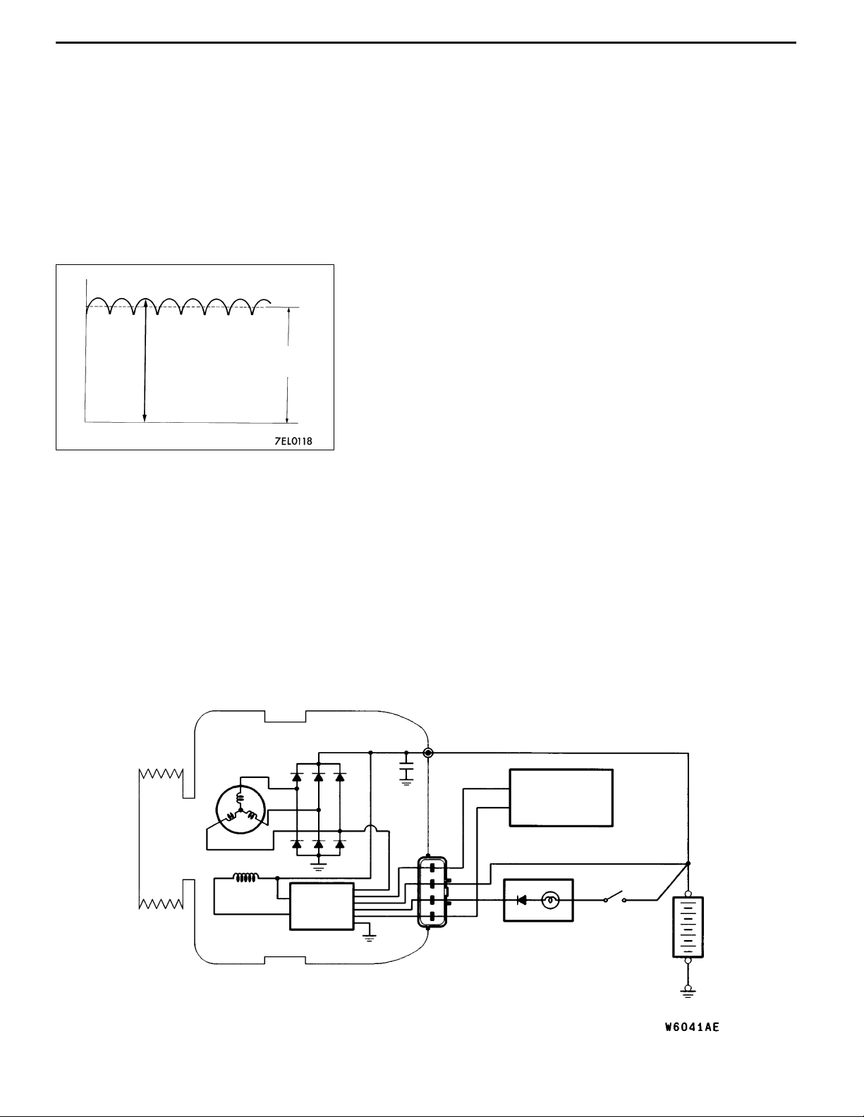
Voltage
OPERATION
Rotation of the excited field coil generates AC voltage in
the stator.
This alternating current is rectified through diodes to DC
Approximately
14.4 V
voltage having a waveform shown in the illustration at left.
The average output voltage fluctuates slightly with the
alternator load condition.
Time
When the ignition switch is turned on, current flows
in the field coil and initial excitation of the field
coil occurs.
When the stator coil begins to generate power after
the engine is started, the field coil is excited by
the output current of the stator coil.
The alternator output voltage rises as the field
current increases and it falls as the field current
decreases. When the battery voltage (alternator
S terminal voltage) reaches a regulated voltage
SYSTEM DIAGRAM
of approximately 14.4 V, the field current is cut
off. When the battery voltage drops below the
regulated voltage, the voltage regulator regulates
the output voltage to a constant level by controlling
the field current.
In addition, when the field current is constant, the
alternator output voltage rises as the engine speed
increases.
Stator coil
Field coil
Voltage
regulator
B
Engine-ECU
G
S
L
FR
Charging
warning lamp
Ignition
switch
Battery
Page 3

ENGINE ELECTRICAL - Charging System
t
V
ALTERNATOR SPECIFICATIONS
Items Specifications
Type Battery voltage sensing
Rated output V/A 12/90
Voltage regulator Electronic built-in type
SERVICE SPECIFICATIONS
Items Standard value Limit
Alternator output line voltage drop (at 30 A) V - max. 0.3
16-3
Regulated voltage ambient
emp. atvoltage regulator
Output current - 70 % of normal output current
Rotor coil resistance Ω Approx. 3 - 5 -
Protrusion length of brush mm - 2
-20_C 14.2- 15.4 -
20_C 13.9-14.9 -
60_C 13.4- 14.6 -
80_C 13.1- 14.5 -
SPECIAL TOOL
Tool Number Name Use
MB991519 Alternator test
harness
Checking the alternator (S terminal voltage)
Page 4
16-4
ENGINE ELECTRICAL - Charging System
ON-VEHICLE SERVICE
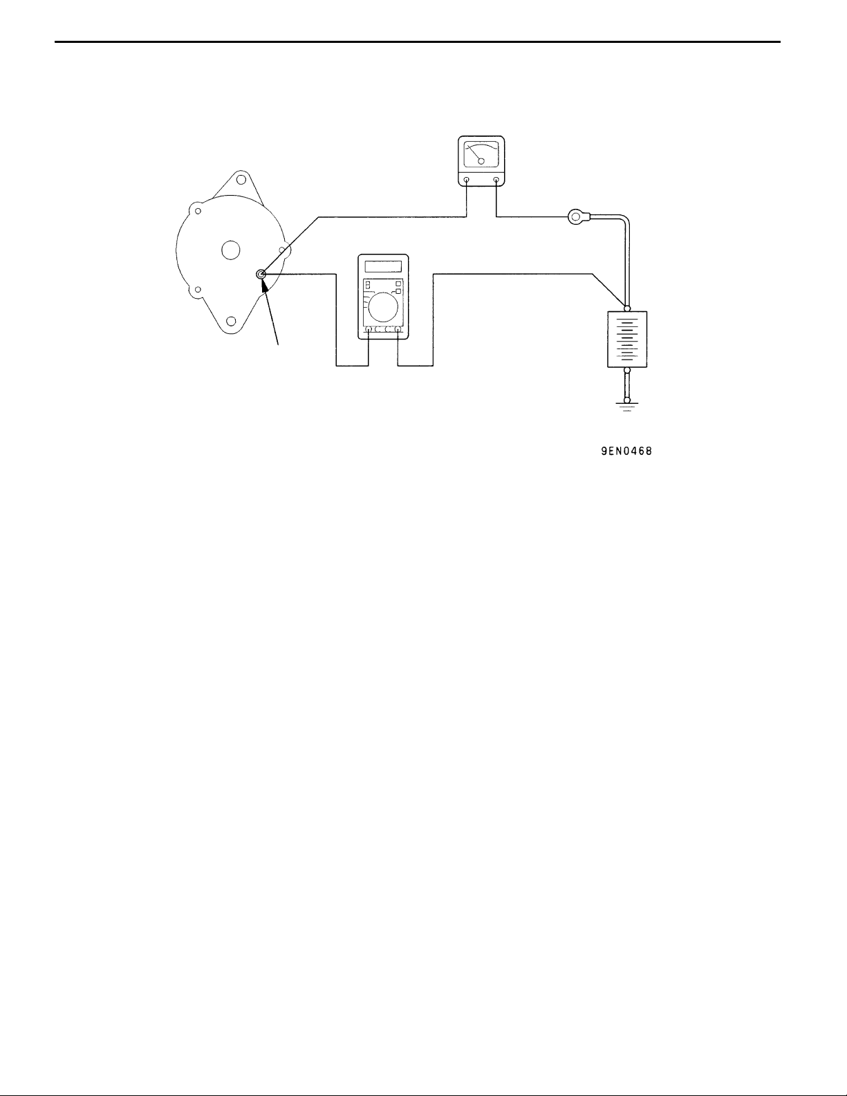
ALTERNATOR OUTPUT LINE VOLTAGE DROP TEST
+-
Alternator
Voltmeter
Terminal B
This test determines whether the wiring from the
alternator “B” terminal to the battery (+) terminal
(including the fusible line) is in a good condition
or not.
(1) Always be sure to check the following before
the test.
D Alternator installation
D Alternator drive belt tension
(Refer to GROUP 11 - On-vehicle Service.)
D Fusible link
D Abnormal noise from the alternator while
the engine is running
(2) Turn the ignition switch to the “LOCK” (OFF)
position.
(3) Disconnect the negative battery cable.
(4) Disconnect the alternator output wire from the
alternator “B” terminal and connect a DC test
ammeter with a range of 0 - 100 A in series
+-
Ammeter
Battery
between the “B” terminal and the disconnected
output wire. (Connect the (+) lead of the
ammeter to the “B” terminal, and then connect
the (- ) lead of the ammeter to the disconnected
output wire.)
NOTE
An inductive-type ammeter which enables
measurements to be taken without
disconnecting the alternator output wire should
be recommended. Using this equipment will
lessen the possibility of a voltage drop caused
by a loose “B” terminal connection.
(5) Connect a digital-type voltmeter between the
alternator “B” terminal and the battery (+)
terminal. (Connect the (+) lead of the voltmeter
to the “B” terminal and the connect the (- ) lead
of the voltmeter to the battery (+) cable.)
Page 5
ENGINE ELECTRICAL - Charging System
16-5
(6) Reconnect the negative battery cable.
(7) Connect a tachometer or the MUT-II.
(Refer to GROUP 11 - On-vehicle Service.)
(8) Leave the hood open.
(9) Start the engine.
(10)With the engine running at 2,500 r/min, turn
the headlamps and other lamps on and off
to adjust the alternator load so that the value
displayed on the ammeter is slightly above 30
A.
Adjust the engine speed by gradually
decreasing it until the value displayed on the
ammeter is 30 A. Take a reading of the value
displayed on the voltmeter at this time.
Limit: max. 0.3 V
NOTE
When the alternator output is high and the value
displayed on the ammeter does not decrease
until 30 A, set the value to 40 A. Read the
value displayed on the voltmeter at this time.
When the value range is 40 A, the limit is max.
0.4 V.
(11) If the value displayed on the voltmeter is above
the limit value, there is probably a malfunction
in the alternator output wire, so check the wiring
between the alternator “B” terminal and the
battery (+) terminal (including fusible link).
If a terminal is not sufficiently tight or if the
harness has become discolored due to
overheating, repair and then test again.
(12)After the test, run the engine at idle.
(13)Turn off all lamps and the ignition switch.
(14)Remove the tachometer or the MUT-II.
(15)Disconnect the negative battery cable.
(16)Disconnect the ammeter and voltmeter.
(17)Connect the alternator output wire to the
alternator “B” terminal.
(18)Connect the negative battery cable.
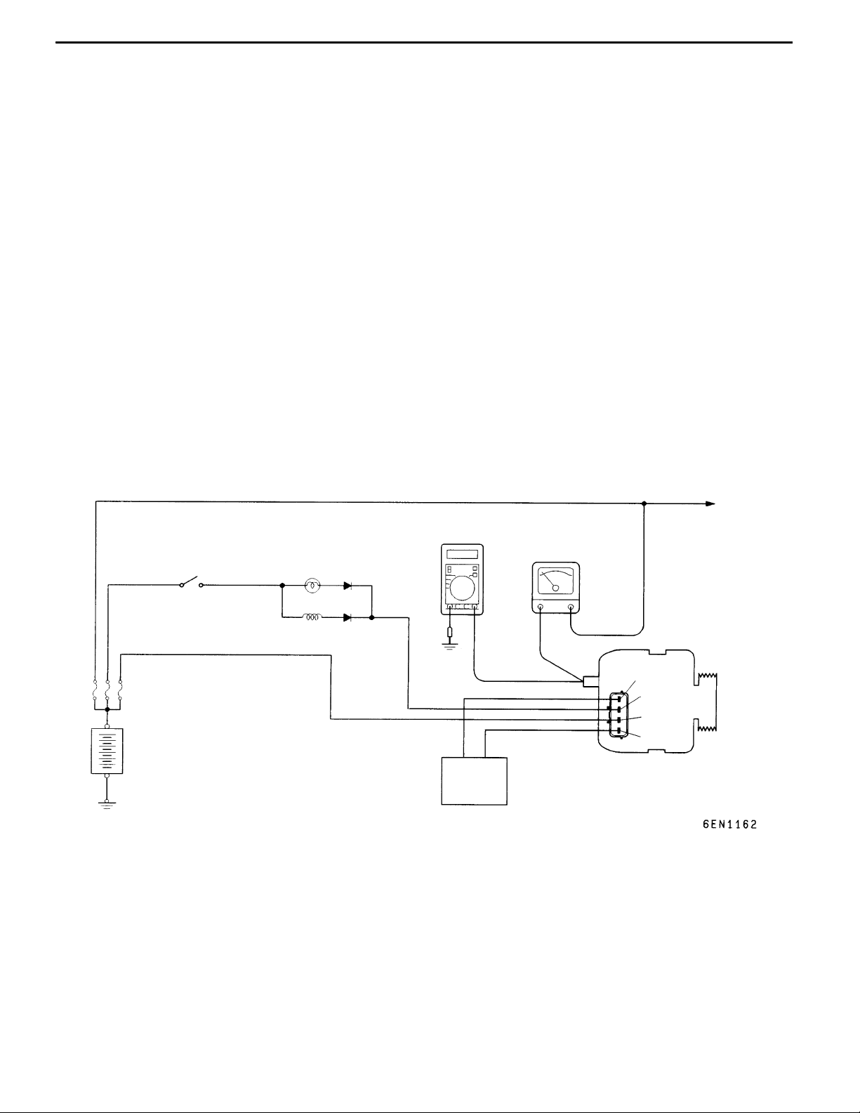
OUTPUT CURRENT TEST
Charging warning lamp
Ignition switch
Alternator relay
Battery
Voltmeter
Ammeter
+-+-
B
Engine-ECU
Load
FR
L
S
G
Alternator
Page 6

16-6
ENGINE ELECTRICAL - Charging System
This test determines whether the alternator output
current is normal.
(1) Before the test, always be sure to check the
following.
D Alternator installation
D Battery (Refer to GROUP 54 - Battery.)
NOTE
The battery should be slightly discharged.
The load needed by a fully-charged battery
is insufficient for an accurate test.
D Alternator drive belt tension
(Refer to GROUP 11 - On-vehicle Service.)
D Fusible link
D Abnormal noise from the alternator while
the engine is running.
(2) Turn the ignition switch to the “LOCK” (OFF)
position.
(3) Disconnect the negative battery cable.
(4) Disconnect the alternator output wire from the
alternator “B” terminal. Connect a DC test
ammeter with a range of 0 - 100 A in series
between the “B” terminal and the disconnected
output wire. (Connect the (+) lead of the
ammeter to the “B” terminal. Connect the ( - )
lead of the ammeter to the disconnected output
wire.)
Caution
Never use clips but tighten bolts and nuts
to connect the line. Otherwise loose
connections (e.g. using clips) will lead to
a serious accident because of high current.
NOTE
An inductive-type ammeter which enables
measurements to be taken without
disconnecting the alternator output wire should
be recommended.
(5) Connect a voltmeter with a range of 0 - 20 V
between the alternator “B” terminal and the
earth. (Connect the (+) lead of the voltmeter
to the “B” terminal, and then connect the ( - )
lead of the voltmeter to the earth.)
(6) Connect the negative battery cable.
(7) Connect a tachometer or the MUT-II.
(Refer to GROUP 11 - On-vehicle Service.)
(8) Leave the hood open.
(9) Check that the reading on the voltmeter is equal
to the battery voltage.
NOTE
If the voltage is 0 V, the cause is probably
an open circuit in the wire or fusible link between
the alternator “B” terminal and the battery (+)
terminal.
(10)Turn the light switch on to turn on headlamps
and then start the engine.
(11) Immediately after setting the headlamps to high
beam and turning the heater blower switch to
the high revolution position, increase the engine
speed to 2,500 r/min and read the maximum
current output value displayed on the ammeter.
Limit: 70 % of normal current output
NOTE
D For the nominal current output, refer to the
Alternator Specifications.
D Because the current from the battery will
soon drop after the engine is started, the
above step should be carried out as quickly
as possible in order to obtain the maximum
current output value.
D The current output value will depend on
the electrical load and the temperature of
the alternator body.
D If the electrical load is small while testing,
the specified level of current may not be
output even though the alternator is normal.
In such cases, increase the electrical load
by leaving the headlamps turned on for
some time to discharge the battery or by
using the lighting system in another vehicle,
and then test again.
D The specified level of current also may not
be output if the temperature of the alternator
body or the ambient temperature is too
high. In such cases, cool the alternator and
then test again.
(12)The reading on the ammeter should be above
the limit value. If the reading is below the limit
value and the alternator output wire is normal,
remove the alternator from the engine and
check the alternator.
(13)Run the engine at idle after the test.
(14)Turn the ignition switch to the “LOCK” (OFF)
position.
(15)Remove the tachometer or the MUT-II.
(16)Disconnect the negative battery cable.
(17)Disconnect the ammeter and voltmeter.
(18)Connect the alternator output wire to the
alternator “B” terminal.
(19)Connect the negative battery cable.
Page 7
ENGINE ELECTRICAL - Charging System
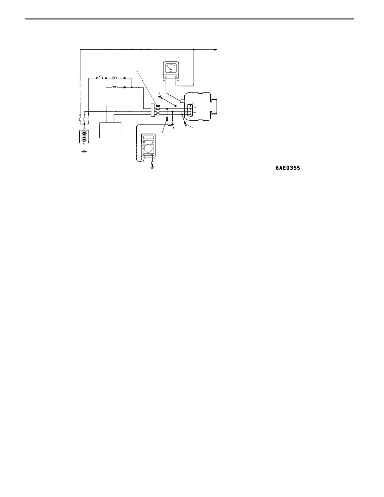
REGULATED VOLTAGE TEST
Ignition
switch
MB991519
Black
Ammeter
16-7
Load
B
FR
L
S
G
Alternator
Voltmeter
Battery
Engine-ECU
Red
Yellow
This test determines whether the voltage regulator
is correctly controlling the alternator output voltage.
(1) Always be sure to check the following before
the test.
D Alternator installation
D Check that the battery installed in the
vehicle is fully charged.
(Refer to GROUP 54 - Battery.)
D Alternator drive belt tension
(Refer to GROUP 11 - On-vehicle Service.)
D Fusible link
D Abnormal noise from the alternator while
the engine is running
(2) Turn the ignition switch to the “LOCK” (OFF)
position.
(3) Disconnect the negative battery cable.
(4) Use the special tool (Alternator test harness:
MB991519) to connect a digital voltmeter
between the alternator S terminal and earth.
(Connect the (+) lead of the voltmeter to the
“S” terminal, and then connect the (−) lead of
the voltmeter to a secure earth or to the battery
(−) terminal.)
(5) Disconnect the alternator output wire from the
alternator “B” terminal.
Blue
(6) Connect a DC test ammeter with a range of
0 - 100 A in series between the “B” terminal
and the disconnected output wire. (Connect
the (+) lead of the ammeter to the “B” terminal.
Connect the ( - ) lead of the ammeter to the
disconnected output wire.)
(7) Reconnect the negative battery cable.
(8) Connect a tachometer or the MUT-II. (Refer
to GROUP 11 - On-vehicle Service.)
(9) Turn the ignition switch to the ON position and
check that the reading on the voltmeter is equal
to the battery voltage.
NOTE
If the voltage is 0 V, the cause is probably
an open circuit in the wire or fusible link between
the alternator “S” terminal and the battery (+)
terminal.
(10)Turn all lamps and accessories off.
(11) Start the engine.
(12)Increase the engine speed to 2,500 r/min.
(13)Read the value displayed on the voltmeter when
the alternator output current alternator
becomes 10 A or less.
Page 8
16-8
ENGINE ELECTRICAL - Charging System
(14)If the voltage reading conforms to the value
in the voltage regulation, then the voltage
regulator is operating normally.
If the voltage is not within the standard value,
there is a malfunction of the voltage regulator
or of the alternator.
(15)After the test, lower the engine speed to the
idle speed.
(17)Remove the tachometer or the MUT-II.
(18)Disconnect the negative battery cable.
(19)Disconnect the ammeter and voltmeter.
(20)Connect the alternator output wire to the
alternator “B” terminal.
(21)Remove the special tool, and return the
connector to the original condition.
(22)Connect the negative battery cable.
(16)Turn the ignition switch to the “LOCK” (OFF)
position.
Voltage Regulation Table
Standard value:
Inspection terminal Voltage regulator ambient temperature _C Voltage V
Terminal “S” -20 14.2 - 15.4
20 13.9 - 14.9
60 13.4 - 14.6
80 13.1 - 14.5
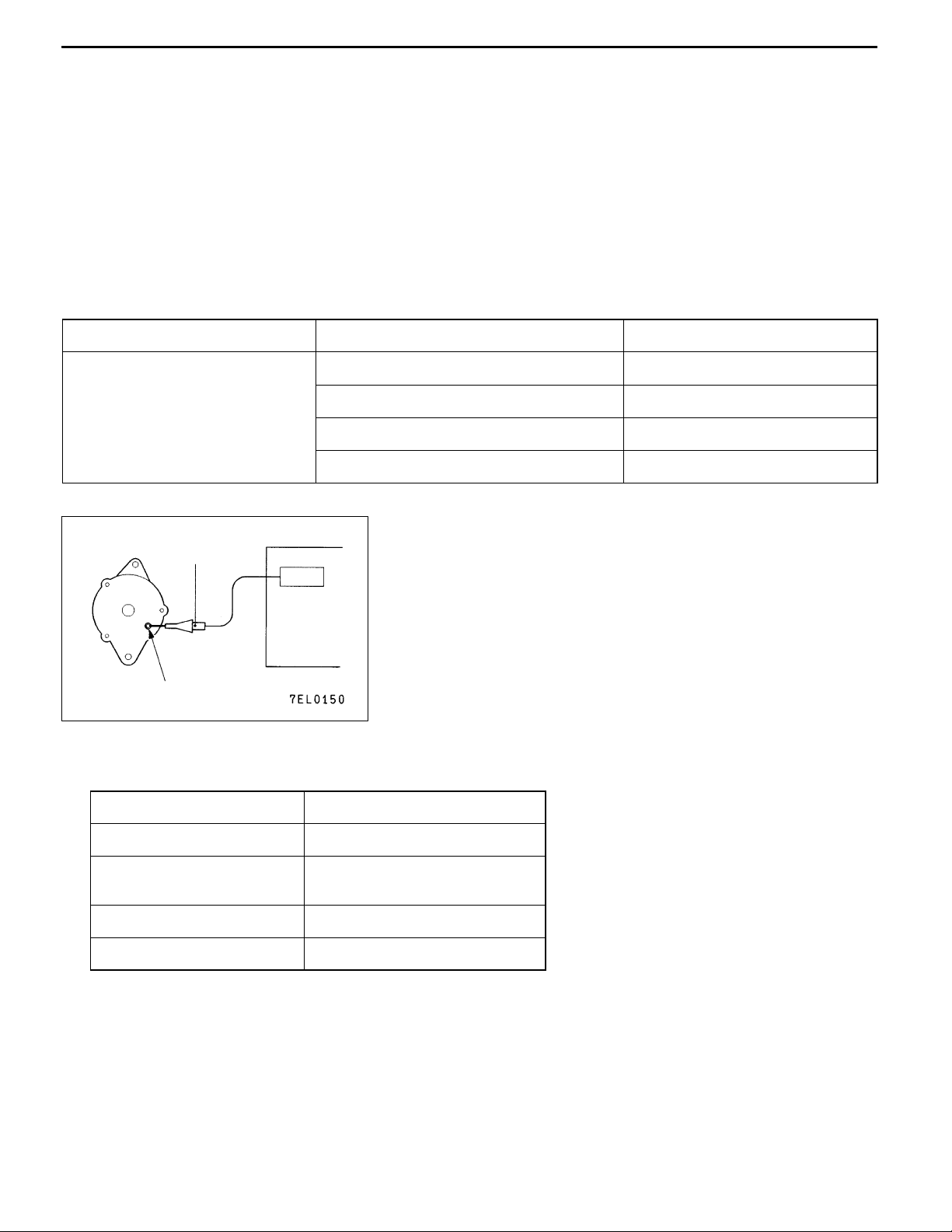
WAVEFORM CHECK USING AN ANALYZER
MEASUREMENT METHOD
Alternator
Special
patterns
pickup
Analyzer
Connect the analyzer special patterns pick-up to the alternator
B terminal.
B terminal
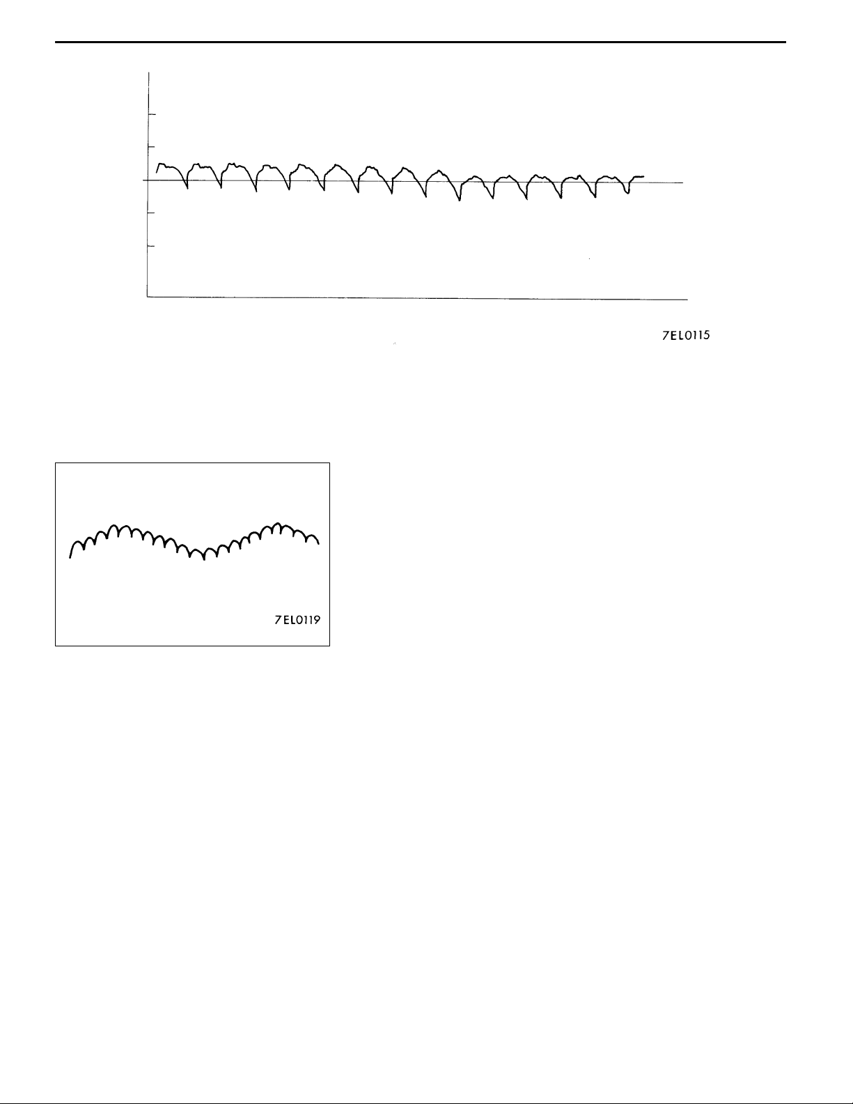
STANDARD WAVEFORM
Observation Conditions
FUNCTION SPECIAL PATTERNS
PATTERN HEIGHT VARIABLE
VARIABLE knob Adjust while viewing the wave-
form.
PATTERN SELECTOR RASTER
Engine speed Curb idle speed
Page 9
Voltageat
alternator
B terminal
0.4
0.2
- 0.2
- 0.4
ENGINE ELECTRICAL - Charging System
0
Time
16-9
NOTE
The voltage waveform of the alternator B terminal can undulate
as shown at left. This waveform is produced when the regulator
operates according to fluctuations in the alternator load
(current), and is normal for the alternator.
In addition, when the voltage waveform reaches an
excessively high value (approximately 2 V or higher at idle),
it often indicates an open circuit due to a brown fuse between
alternator B terminal and battery, but not a defective alternator.
Page 10
16-10
ENGINE ELECTRICAL - Charging System
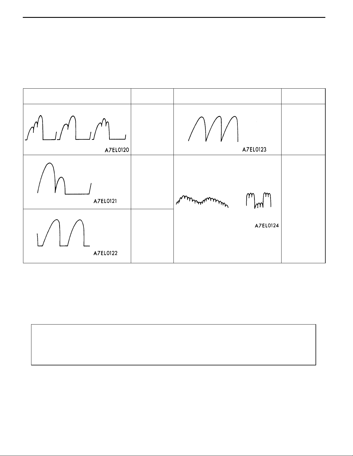
EXAMPLES OF ABNORMAL WAVEFORMS
NOTE
1. The size of the waveform patterns differs largely, depending on the adjustment of the variable knob
on the analyzer.
2. Identification of abnormal waveforms is easier when there is a large output current (regulator is not
operating). (Waveforms can be observed when the headlamps are illuminated.)
3. Check the conditions of the charging warning lamp (illuminated/not illuminated). Also, check the charging
system totally.
Abnormal waveforms Problem
cause
Example 1 Open diode Example 4 Short in
Example 2 Short in diode
Example 3 Broken wire
in stator coil
Abnormal waveforms Problem
cause
stator coil
Example 5 Open
supplementary diode
At this time, the charging warning lamp
is illuminated.
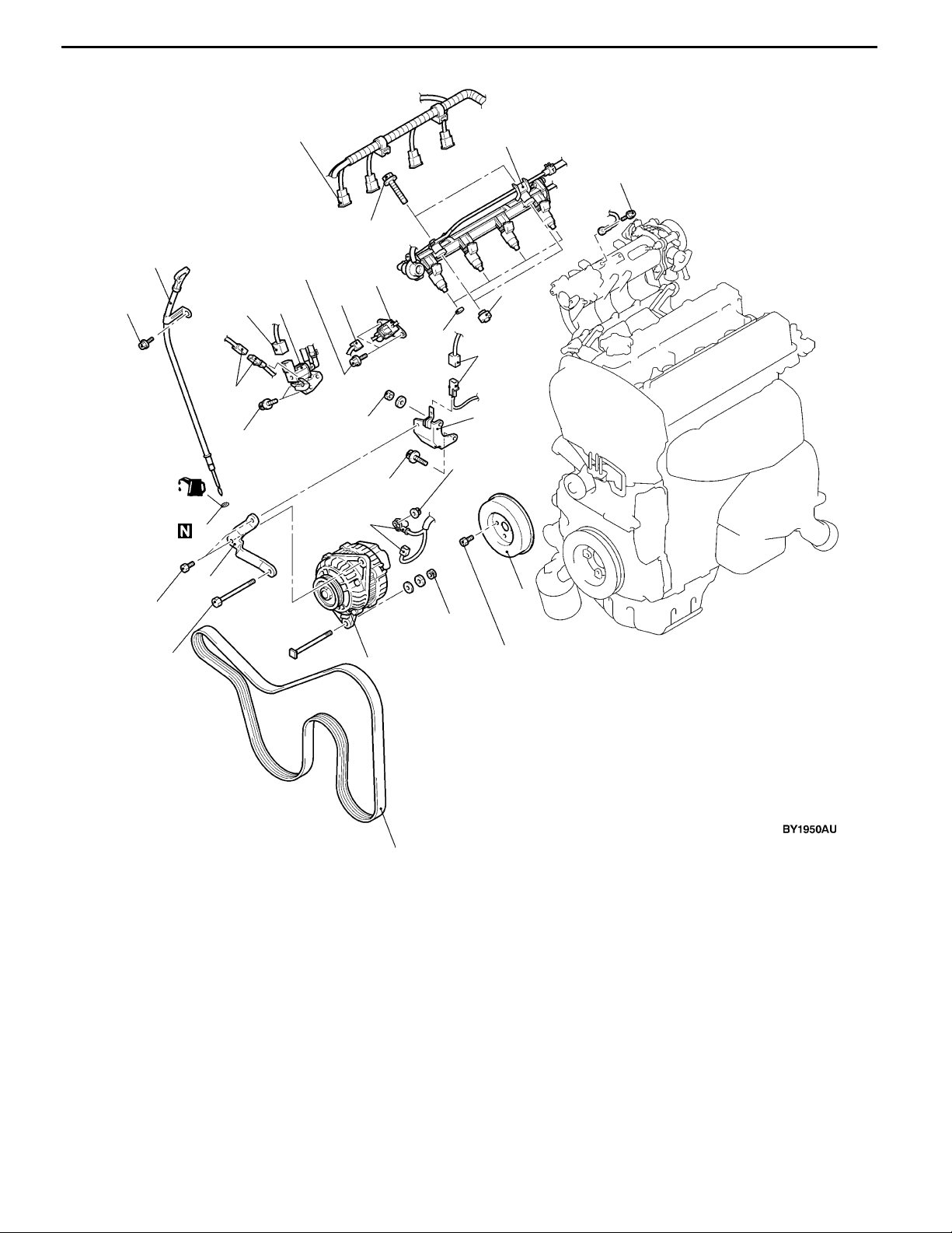
ALTERNATOR
REMOVAL AND INSTALLATION
Caution
If the vehicle is equipped with the Brembo disc brake, during maintenance, take care not to contact
the parts or tools to the caliper because the paint of caliper will be scratched.
Pre-removal and Post-installation Operation
D Under Cover Removal and Installation (Refer to GROUP 51 - Front Bumper.)
D Drive Belt Tension Check (Refer to GROUP 11A - On-vehicle Service.) <After installation only>
D Strut Tower Bar Removal and Installation (Refer to GROUP 42.)
D Crossmember Bar Removal and Installation (Refer to GROUP 32 - Engine Roll Stopper, Centermember.)
D Front Exhaust Pipe Assembly Removal and Installation (Refer to GROUP 15.)
Page 11
ENGINE ELECTRICAL - Charging System
16-11
13 ± 1 N·m
(Engine oil)
22 ± 4 N·m
8
11 ± 1 N·m
9
5.0 ± 1.0 N·m
1
9.0 ± 1.0 N·m
7
6
4
3
10
11
17
5
18
14 ± 3 N·m
9.0 ± 1.0 N·m
2
36 ± 6 N·m
20 ± 2 N·m
13
16
15
44 ± 10 N·m
23 ± 3 N·m
14
12
Removal steps
1. Oil level gauge and guide assembly
2. O-ring
3. Fuel pressure solenoid valve
connector
4. Fuel pressure solenoid valve
assembly
5. Detonation sensor connector
6. Purge control solenoid valve
connector
7. Purge control solenoid valve assembly
8. Injector connector
AA" 9. Delivery pipe, injector, and fuel
pressure regulator assembly
8.8 ± 1.0 N·m
10. Insulator
11. Insulator
AB" 12. Drive belt
13. Alternator connector
D Engine mounting
(Refer to GROUP 32.)
AC" 14. Alternator
15. Water pump pulley
16. Alternator brace
17. Oxygen sensor connector
18. Alternator brace stay
Page 12
16-12
Hole A
ENGINE ELECTRICAL - Charging System
REMOVAL SERVICE POINTS
AA" DELIVERY PIPE, INJECTOR, AND FUEL
PRESSURE REGULATOR ASSEMBLY REMOVAL
After loosening the installed parts, set the related parts
aside to make some space for removing the alternator.
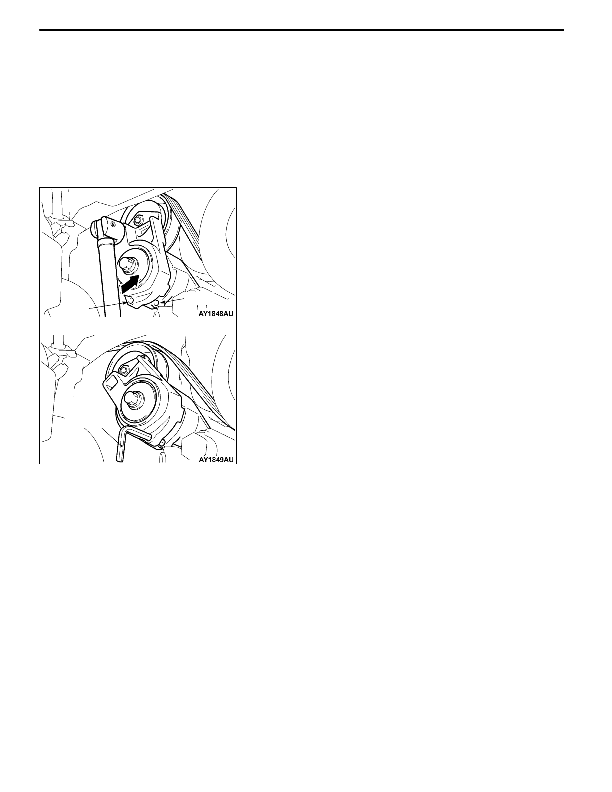
AB" DRIVE BELT REMOVAL
Due to the adoption of the Serpentine drive system with
the auto-tensioner, the following operation is required:
1. Insert the 12.7sq. spinner handle into the tool hole of
the auto-tensioner and rotate it counterclockwise until
the auto-tensioner reaches to the stopper.
2. Align hole A with hole B for fixing by inserting the L-shaped
hexagon wrench, then remove the drive belt.
Hole B
Caution
When the drive belt is reused, use a chalk to
indicate an arrow of rotation direction on the
back of the belt so that it can be re-assembled in
the same direction as before.
L-shaped
hexagon
wrench
AC"ALTERNATOR REMOVAL
Push up the engine with a garage jack to the top and
remove the alternator upward from the engine room.
Page 13

ENGINE ELECTRICAL - Charging System
DISASSEMBLY AND REASSEMBLY
16-13
1
4
3
5
7
6
4
2
12
10
9
8
14
Disassembly steps
AA" 1. Front bracket assembly
AB" 2. Alternator pulley
"BA 3. Rotor
4. Rear bearing
5. Bearing retainer
6. Front bearing
7. Front bracket
13
11
AC" 8. Stator
9. Plate
AC""AA 10. Regulator assembly
11. Brush
12. Packing
13. Rectifier
14. Rear bracket
Page 14

16-14
Rectifier
assembly
ENGINE ELECTRICAL - Charging System
DISASSEMBLY SERVICE POINTS
AA" FRONT BRACKET ASSEMBLY REMOVAL
Insert a flat tip screwdrivers or the like in the clearance between
the front bracket assembly and stator core, to pry open and
separate the stator and front bracket.
Caution
Do not insert a screwdriver too far, or the stator coil gets
damaged.
AB" ALTERNATOR PULLEY REMOV AL
Face pulley side upward, fix the rotor with a work bench
and remove the pulley.
Caution
Use care not to damage the rotor.
AC" STATOR/REGULATOR ASSEMBLY REMOVAL
1. Unsolder the stator with a soldering iron (180 to 250
W). Complete this work within four seconds not to transfer
heat to the diode.
2. When removing rectifier from the regulator assembly,
remove the soldered sections to rectifier.
Soldered
Caution
(1) Use care to make sure that the heat of the soldering
iron is not transmitted to the diodes for a long period.
(2) Use care that no undue force is exerted to the
lead wires of the diodes.
Soldered
Rear bracket
Brush
Wire
Wire
REASSEMBLY SERVICE POINTS
"AA REGULATOR ASSEMBLY INSTALLATION
After installing the regulator assembly, insert a wire into the
hole provided on the rear bracket while pressing in the brush
to fix the brush.
NOTE
The brush is fixed when a wire is inserted, making rotor
installation easier.
Page 15

ENGINE ELECTRICAL - Charging System
"BA ROTOR INSTALLATION
Wire
After installing the rotor, remove the wire used to fix the brush.
INSPECTION
ROTOR CHECK
1. Check the continuity between the rotor coil slip rings,
and replace the rotor if the resistance value is not at
the standard value.
Standard value: 3 - 5 Ω
16-15
2. Check the continuity between the slip ring and core, and
if there is continuity, replace the rotor.
STATOR CHECK
1. Check the continuity between the coil leads, and if there
is continuity, replace the stator.
2. Check the continuity between the coil and core, and if
there is continuity, replace the stator.
Page 16

16-16
ENGINE ELECTRICAL - Charging System
RECTIFIERS CHECK
1. Inspect the (+) heat sink by checking the continuity
between the (+) heat sink and stator coil lead wire
connection terminal using a tester probe.
If there is a continuity at both, the diode is short circuited,
so replace the rectifier.
2. Inspect the ( - ) heat sink by checking the continuity
between the ( - ) heat sink and stator coil lead wire
connection terminal using a tester probe.
If there is a continuity at both, the diode is short circuited,
so replace the rectifier.
Protrusion
length
Soldered
3. Check the diode trio by connecting an ohmmeter to both
ends of each diode and check the continuity of the three
diodes.
If there is a continuity at both ends, or if there is no
continuity, the diode is damaged so replace the rectifier.
BRUSH CHECK
1. Measure the length of the brush protrusion shown in the
illustration, and replace the brush if the measured value
is below the limit value.
Limit: 2 mm or less
2. The brush can be removed if the solder of the brush
lead wire is removed.
3. When installing a new brush, insert the brush into the
holder as shown in the illustration, and then solder the
lead wires.
Page 17

ENGINE ELECTRICAL - Starting System
STARTING SYSTEM
GENERAL INFORMATION
16-17
If the ignition switch is turned to the “START”
position, current flows in the pull-in and holding
coils provided inside magnetic switch, attracting
the plunger. When the plunger is attracted, the
lever connected to the plunger is actuated to
engage the starter clutch.
On the other hand, attracting the plunger will turn
on the magnetic switch, allowing the B terminal
SYSTEM DIAGRAM
Ignition
switch
Battery
Brush
and M terminal to conduct. Thus, current flows to
engage the starter motor.
When the ignition switch is returned to the “ON”
position after starting the engine, the starter clutch
is disengaged from the ring gear.
An overrunning clutch is provided between the
pinion and the armature shaft, to prevent damage
to the starter.
Holding coil
Pull-in coil
Armature
Yoke
Plunger
Lever
Over-running
clutch
Pinion shaft
STARTER MOTOR SPECIFICATIONS
Items Specifications
Type Reduction drive with planetary gear
Rated output kW/V 1.2/12
No. of pinion teeth 8
SERVICE SPECIFICATIONS
Items Standard value Limit
Pinion gap mm 0.5 - 2.0 -
Commutator outer diameter mm 29.4 28.8
Commutator runout mm 0.05 0.1
Commutator undercut mm 0.5 0.2
Brush length mm - 7.0
Page 18

16-18
ENGINE ELECTRICAL - Starting System
STARTER
REMOVAL AND INSTALLATION
Pre-removal and Post-installation Operation
D Under Cover Removal and Installation (Refer to GROUP51 - Front Bumper.)
D Crossmember Bar Removal and Installation (Refer to GROUP 32 - Engine Roll Stopper, Centermember.)
D Front Exhaust Pipe Assembly Removal and Installation (Refer to GROUP 15.)
13 ± 2 N·m
2
30 ± 3 N·m
30 ± 3 N·m
Removal steps
1. Starter connector
2. Starter
INSPECTION
1
Switch
S
B
M
Battery
Field coil wire
PINION GAP ADJUSTMENT
1. Disconnect field coil wire from M-terminal of magnetic
switch.
2. Connect a 12 V battery between S-terminal and
M-terminal.
3. Set switch to “ON” position, and pinion will move out.
Caution
This test must be performed quickly (in less than
10 seconds) to prevent coil from burning.
Pinion
4. Check pinion to stopper clearance (pinion gap) with a
thickness gauge.
Standard value: 0.5 - 2.0 mm
Stopper
Pinion gap
Page 19

ENGINE ELECTRICAL - Starting System
16-19
5. If pinion gap is out of specification, adjust by adding or
removing gaskets between magnetic switch and front
bracket.
MAGNETIC SWITCH PULL-IN TEST
S
1. Disconnect field coil wire from M-terminal of magnetic
switch.
B
M
Battery
2. Connect a 12 V battery between S-terminal and
M-terminal.
Caution
Field coil wire
This test must be performed quickly (in less than
10 seconds) to prevent coil from burning.
3. If pinion moves out, then pull-in coil is good. If it doesn’t,
replace magnetic switch.
MAGNETIC SWITCH HOLD-IN TEST
1. Disconnect field coil wire from M-terminal of magnetic
S
Battery
switch.
2. Connect a 12 V battery between S-terminal and body.
Caution
This test must be performed quickly (in less than 10
seconds) to prevent coil from burning.
Field coil wire
3. Manually pull out the pinion as far as the pinion stopper
position.
4. If pinion remains out, everything is in order. If pinion moves
in, hold-in circuit is open. Replace magnetic switch.
S
B
Starter
motor
Carbon-pile rheostat
FREE RUNNING TEST
1. Place starter motor in a vise equipped with soft jaws
and connect a fully-charged 12 V battery to starter motor
M
A
Ammeter
as follows:
2. Connect a test ammeter (100-ampere scale) and carbon
pile rheostat in series with battery positive post and starter
V
Voltmeter
Battery
motor terminal.
3. Connect a voltmeter (15 V scale) across starter motor.
4. Rotate carbon pile to full-resistance position.
5. Connect battery cable from battery negative post to starter
motor body.
6. Adjust the rheostat until the battery voltage shown by
the voltmeter is 11 V Reduction.
7. Confirm that the maximum amperage is within the
specifications and that the starter motor turns smoothly
and freely.
Current:
max. 90 A
Page 20

16-20
ENGINE ELECTRICAL - Starting System
MAGNETIC SWITCH RETURN TEST
1. Disconnect field coil wire from M-terminal of magnetic
switch.
M
Battery
Field coil wire
2. Connect a 12 V battery between M-terminal and body.
Caution
This test must be performed quickly (in less than
10 seconds) to prevent coil from burning.
3. Pull pinion out and release. If pinion quickly returns to
its original position, everything is in order. If it doesn’t,
replace magnetic switch.
Caution
Be careful not to get your fingers caught when pulling
out the pinion.
Page 21

ENGINE ELECTRICAL - Starting System
DISASSEMBLY AND REASSEMBLY
16-21
3
13
14
16
11
12
15
21
2
20
19
18
17
5
22
Disassembly steps
1. Cover
2. Screw
AA" 3. Magnetic switch
4. Screw
5. Through
6. Rear bracket
7. Brush holder
8. Rear bearing
AB" 9. Armature
10. Yoke assembly
AB" 1 1. Ball
10
8
7
9
AC""AA 17. Snap ring
AC""AA 18. Stop ring
4
6
12. Packing A
13. Packing B
14. Plate
15. Planetary gear
16. Lever
19. Overrunning clutch
20. Internal gear
21. Planetary gear holder
22. Front bracket
1
Page 22

16-22
“B” terminal
“M” terminal
ENGINE ELECTRICAL - Starting System
DISASSEMBLY SERVICE POINTS
“S” terminal
Field coil
wire
AA" MAGNETIC SWITCH REMOVAL
Disconnect field coil wire from “M” terminal of magnetic switch.
AB" ARMATURE/BALL REMOVAL
Caution
When removing the armature, take care not to lose the
ball (which is used as a bearing) in the armature end.
Stop ring
Snap ring pliers
Socket
Pinion gear
Overrunning
clutch
Snap ring
Pinion gear
Overrunning
clutch
AC"SNAP RING/STOP RING REMOVAL
1. Press stop ring off snap ring with a suitable socket.
2. Remove snap ring with snap ring pliers and then remove
stop ring and overrunning clutch.
STARTER MOTOR PARTS CLEANING
1. Do not immerse parts in cleaning solvent. Immersing the
yoke and field coil assembly and/or armature will damage
insulation. Wipe motor assembly with a cloth only.
2. Do not immerse drive unit in cleaning solvent. Overrunning
clutch is pre-lubricated at the factory and solvent will wash
lubrication from clutch
3. The drive unit may be cleaned with a brush moistened
with cleaning solvent and wiped dry with a cloth.
Page 23

Stop ring
Overrunning
clutch
ENGINE ELECTRICAL - Starting System
REASSEMBLY SERVICE POINT
"AA STOP RING/SNAP RING INSTALLATION
Using a suitable pulling tool, pull overrunning clutch stop ring
over snap ring.
Stop ring
Snap ring
INSPECTION
COMMUTATOR CHECK
1. Place the armature in a pair of “V” blocks and check
the runout with a dial indicator.
Standard value: 0.05 mm
Limit: 0.1 mm
16-23
Segment
Undercut
Mica
2. Measure the commutator outer diameter.
Standard value: 29.4 mm
Limit: 28.8 mm
3. Check the undercut depth between segments.
Standard value: 0.5 mm
Limit: 0.2 mm
BRUSH HOLDER CHECK
Confirm that the spring is activated when the brush is pressed
into the brush holder by hand.
Replace the brush holder if the spring is not activated.
Page 24

16-24
Lock
Free
ENGINE ELECTRICAL - Starting System
OVERRUNNING CLUTCH CHECK
1. While holding clutch housing, rotate the pinion. Drive
pinion should rotate smoothly in one direction, but should
not rotate in opposite direction. If clutch does not function
properly, replace overrunning clutch assembly.
2. Inspect pinion for wear or burrs. If pinion is worn or burred,
replace overrunning clutch assembly. If pinion is damaged,
also inspect ring gear for wear or burrs.
FRONT AND REAR BRACKET BUSHING CHECK
Inspect bushing for wear or burrs. If bushing is worn or burred,
replace front bracket assembly or rear bracket assembly.
Growler
Length
BRUSH REPLACEMENT
1. Check the surface contacting the commutator for
roughness and the brush length.
Limit value: 7.0 mm
2. If the limit is exceeded, replace the brush holder.
ARMATURE TEST
ARMATURE COIL SHORT-CIRCUIT TEST
1. Check that the armature coil is not grounded.
2. Place armature in a growler.
3. Hold a thin steel blade parallel and just above while rotating
armature slowly in growler. A shorted armature will cause
blade to vibrate and be attracted to the core. Replace
shorted armature.
ARMATURE COIL EARTH TEST
Check the insulation between each commutator segment and
armature coil core.
If there is no continuity, the insulation is in order.
Page 25

ENGINE ELECTRICAL - Starting System
16-25
ARMATURE COIL OPEN-CIRCUIT INSPECTION
Check the continuity between segments. If there is continuity,
the coil is in order.
MAGNETIC SWITCH
A
“M” terminal
COIL DISCONNECTION TEST
D Confirm that there is continuity between the “M” terminal
and body A.
D If there is no continuity, replace the magnetic switch.
“B” terminal
“M” terminal
“B” terminal
“M” terminal
CONTACT CONTACTING STATE CHECK
D Confirm that there is no continuity between the “B” terminal
and “M” terminal.
D If there is continuity, replace the magnetic switch.
CONTACT CONTACTING STATE CHECK
D Press the end of the magnetic switch in with force, and
close the internal contact. Confirm that there is continuity
between the “B” terminal and “M” terminal in this state.
D If there is no continuity, replace the magnetic switch.
Page 26

16-26
ENGINE ELECTRICAL - Ignition System
IGNITION SYSTEM
GENERAL INFORMATION
This system is equipped with two ignition coils (A
and B) with built-in power transistors for the No.
1 and No. 4 cylinders and the No. 2 and No. 3
cylinders respectively.
Interruption of the primary current flowing in the
primary side of ignition coil A generates a high
voltage in the secondary side of ignition coil A.
The high voltage thus generated is applied to the
spark plugs of No. 1 and No. 4 cylinders to generate
sparks. At the time that the sparks are generated
at both spark plugs, if one cylinder is at the
compression stroke, the other cylinder is at the
exhaust stroke, so that ignition of the compressed
air/fuel mixture occurs only for the cylinder which
is at the compression stroke.
In the same way, when the primary current flowing
in ignition coil B is interrupted, the high voltage
thus generated is applied to the spark plugs of
No. 2 and No. 3 cylinders.
The Engine-ECU turns the two power transistors
inside the ignition coils alternately on and off. This
SYSTEM DIAGRAM
Air flow sensor
Barometric pressure sensor
causes the primary currents in the ignition coils
to be alternately interrupted and allowed to flow
to fire the cylinders in the order 1-3-4-2.
The Engine-ECU determines which ignition coil
should be controlled by means of the signals from
the camshaft position sensor which is incorporated
in the camshaft and from the crank angle sensor
which is incorporated in the crankshaft. It also
detects the crankshaft position in order to provide
ignition at the most appropriate timing in response
to the engine operation conditions. It also detects
the crankshaft position in order to provide ignition
at the most appropriate timing in response to the
engine operation conditions.
When the engine is cold or operated at high
altitudes, the ignition timing is slightly advanced
to provide optimum performance.
When the automatic transmission shifts gears, the
ignition timing is also retarded in order to reduce
output torque, thereby alleviating shifting shocks.
Ignition switch
Battery
Intake air temperature sensor
Engine coolanttemperaturesensor
Camshaft position sensor
Crank angle sensor
Ignition switch - ST
Vehicle speed signal
Detonation sensor
Engine-ECU
To tachometer
Spark plug
Cylinder No.
Ignition coil A
Ignition coil B
14
23
Page 27

ENGINE ELECTRICAL - Ignition System
IGNITION COIL SPECIFICATIONS
Items Specifications
Type Molded 2-coil
SPARK PLUG SPECIFICATIONS
Items Specifications
NGK IGR7A-G
DENSO VW22PR-DA7
SERVICE SPECIFICATIONS
IGNITION COIL
Items Standard value
Secondary coil resistance kΩ 8.5 - 11.5
SPARK PLUG
16-27
Items Standard value Limit
Spark plug gap mm 0.6 - 0.7 0.75
RESISTIVE CORD
Items Limit
Resistance kΩ max. 22
SPECIAL TOOL
Tool Number Name Use
MD998773 Detonation sensor
wrench
Detonation sensor removal and installation
Page 28

16-28
ENGINE ELECTRICAL - Ignition System
ON-VEHICLE SERVICE
IGNITION COIL (WITH BUILT-IN POWER TRANSISTOR) CHECK
Check by the following procedure, and replace if there is
a malfunction.
SECONDARY COIL RESISTANCE CHECK
Measure the resistance between the high-voltage terminals
of the ignition coil.
Standard value: 8.5 - 11.5 kΩ
PRIMARY COIL AND POWER TRANSISTOR
CONTINUITY CHECK
NOTE
1. An analogue-type circuit tester should be used.
2. Connect the negative ( -) prove of the circuit tester to
terminal 1.
Caution
This test must be performed quickly (in less than 10
seconds) to prevent coil from burning and power
transistor from breakage.
1.5V power across 2 - 3 Continuity across 1 - 2
When energized Ye s
When not energized No
RESISTIVE CORD CHECK
Measure the resistance of the all spark plug cables.
1. Check cap and coating for cracks.
2. Measure resistance.
Limit: Max. 22 kΩ
Page 29

ENGINE ELECTRICAL - Ignition System
16-29
SPARK PLUG CHECK, CLEANING AND REPLACEMENT
SPARK PLUG GAP CHECK
Caution
1. Do not adjust the gap of the iridium plug.
2. Cleaning of the iridium plug could damage the tip of the electrode. Thus, if the plug must
be cleaned because of soot, etc., use a plug cleaner and clean within a short time of 20 seconds
or less to protect the electrode. Do not use a wire brush, etc.
3. Even when the functions of the iridium plug are normal, the electrode section may be blackened.
However, the adhered carbon has properties that easily burned off compared to the conventional
type, so there is no problem. Check the quality of the spark plug by checking the insulation
resistance.
Check the plug gap, and replace if the checked value is more than the limit value.
Standard value, limit value:
Maker Model Standard value (mm) Limit value (mm)
NGK IGR7A-G 0.6 - 0.7 0.75
DENSO VW22PR-DA7 0.6 - 0.7 0.75
SPARK PLUG INSULATION RESISTANCE CHECK
Measure the insulation resistance of the spark plug, and
replace if the measured value is less than the limit value.
Limit value: 1 MΩ
CAMSHAFT POSITION SENSOR CHECK
Refer to GROUP 13A - Troubleshooting.
CRANK ANGLE SENSOR CHECK
Refer to GROUP 13A - Troubleshooting.
DETONATION SENSOR CHECK
Check the detonation sensor circuit if self-diagnosis code,
No. 31 is shown.
NOTE
For information concerning the self-diagnosis codes, refer
to GROUP 13A - Troubleshooting.
Page 30

16-30
ENGINE ELECTRICAL - Ignition System
WAVEFORM CHECK USING AN ANALYZER
Ignition Secondary Voltage Waveform Check
MEASUREMENT METHOD
1. Clamp the secondary pickup around the spark plug cable.
NOTE
(1) The peak ignition voltage will be reversed when the
spark cables No. 2 and No. 4, or No. 1 and No.
3 cylinders are clamped.
(2) Because of the two-cylinder simultaneous ignition
system, the waveforms for two cylinders in each group
appear during waveform observation (No. 1 cylinder
- No. 4 cylinder, No. 2 cylinder - No. 3 cylinder).
However, waveform observation is only applicable
for the cylinder with the spark plug cable clamped
by the secondary pickup.
(3) Identifying which cylinder waveform is displayed can
be difficult. For reference, remember that the
waveform of the cylinder attached to the secondary
pickup will be displayed as stable.
2. Clamp the spark plug cable with the trigger pickup.
NOTE
Clamp the trigger pickup to the same spark plug cable
clamped by the secondary pickup.
Page 31

ENGINE ELECTRICAL - Ignition System
STANDARD WAVEFORM
Observation Conditions
Function Secondary
Pattern height High (or Low)
Pattern selector Raster
Engine revolutions Curb idle speed
16-31
kV
Ignition voltage
(point D)
Dwell
section
Secondary
ignition
voltage
waveform
Point C
Spark line (point A)
Wave damping
reductionsection
(point B)
Time
Observation Condition (The only change from above condition is the pattern selector.)
Pattern selector Display
kV
Secondary
ignition
voltage
waveform
No. 4 cylinder
No. 2 cylinder
ignition noise
0
2
Neutral section
No. 1 cylinder
No. 3 cylinder
ignition noise
Time
Page 32

16-32
ENGINE ELECTRICAL - Ignition System
WAVEFORM OBSERVATION POINTS
Point A: The height, length and slope of the spark line show the following trends (Refer to abnormal
waveform examples, 1, 2, 3 and 4).
Spark line Plug gap Condition of
electrode
Length Long Small Normal Low Rich Advanced Leak
Short Large Large wear High Lean Retarded High
Height High Large Large wear High Lean Retarded High
Low Small Normal Low Rich Advanced Leak
Slope Large Plug is fouled - - - -
Compression
force
Concentration of
air mixture
Ignition timing Spark plug
cable
resistance
resistance
Point B: Number of vibration in reduction vibration section (Refer to abnormal waveform example 5)
Number of vibrations Coil and condenser
Three or more Normal
Except above Abnormal
Point C: Number of vibrations at beginning of dwell section (Refer to abnormal waveform example 5)
Number of vibrations Coil
5 - 6 or higher Normal
Except above Abnormal
Point D: Ignition voltage height (distribution per each cylinder) shows the following trends.
Ignition
voltage
High Large Large wear High Lean Retarded High resistance
Low Small Normal Low Rich Advanced Leak
Plug gap Condition of
electrode
Compression
force
Concentration of
air mixture
Ignition timing Spark plug cable
Page 33

ENGINE ELECTRICAL - Ignition System
EXAMPLES OF ABNORMAL WAVEFORMS
Abnormal waveform Wave characteristics Cause of problem
16-33
Example 1
01P0215
Example 2 Spark line is low and long, and is
Example 3 Spark line is low and long, and is
Spark line is high and short. Spark plug gap is too large.
sloping.
Also, the second half of the spark line
is distorted. This could be a result of
misfiring.
sloping. However, there is almost no
spark line distortion.
Spark plug gap is too small.
Spark plug gap is fouled.
Example 4 Spark line is high and short.
Difficult to distinguish between this
and abnormal waveform example 1.
Example 5 No waves in wave damping section. Layer short in ignition coil
Spark plug cable is nearly falling off.
(Causing a dual ignition)
Page 34

16-34
ENGINE ELECTRICAL - Ignition System
IGNITION COIL
REMOVAL AND INSTALLATION
Pre-removal and Post-installation Operation
Center Cover Removal and Installation (Refer to GROUP 11A - Camshaft and Camshaft Oil Seal.)
10 ± 2 N·m
10 ± 2 N·m
1
25 ± 4 N·m
Removal steps
1. Ignition coil connector
2. Spark plug cable No.1
3. Spark plug cable No.3
2
1
4
4
3
5
4. Ignition coil
5. Spark plug
Page 35

ENGINE ELECTRICAL - Ignition System
CAMSHAFT POSITION SENSOR
REMOVAL AND INSTALLATION
16-35
3
8.8 ± 1.0 N·m
Removal steps
1. Camshaft position sensor connector
2. Camshaft position sensor
3. O-ring
2
1
CRANK ANGLE SENSOR
REMOVAL AND INSTALLATION
Caution
If the vehicle is equipped with the Brembo disc brake, during maintenance, take care not to contact
the parts or tools to the caliper because the paint of caliper will be scratched.
Pre-removal and Post-installation Operation
D Center Cover Removal and Installation (Refer to GROUP 11A - Camshaft and Camshaft Oil Seal.)
D Timing Belt Removal and Installation (Refer to GROUP 11A.)
D Reserve Tank Removal and Installation (Refer to GROUP 14 - Radiator.)
Page 36

16-36
ENGINE ELECTRICAL - Ignition System
8.8 ± 1.0 N·m
5
12 ± 2 N·m
22 ± 4 N·m
22 ± 4 N·m
2
12 ± 2 N·m
7
1
22 ± 4 N·m
40 ± 5 N·m
49 ± 9 N·m
3
4
49 ± 9 N·m
6
8.8 ± 1.0 N·m
Removal steps
1. Power steering oil pressure switch
connector
2. Heat protector
AA" 3. Power steering oil pump, bracket and
oil reservoir assembly
REMOVAL SERVICE POINT
AA" POWER STEERING OIL PUMP, BRACKET AND
Remove the power steering oil pump, bracket and oil reservoir
assembly with the hose attached from the bracket.
NOTE
Tie the removed oil pump with a rope and set aside where
they cannot hinder the removal of the power steering oil pump
bracket.
4. Power steering oil pump bracket
5. Crank angle sensor connector
6. Crank angle sensor
7. Connector bracket
OIL RESERVOIR ASSEMBLY REMOVAL
Page 37

ENGINE ELECTRICAL - Ignition System
DETONATION SENSOR
REMOVAL AND INSTALLATION
Caution
Do not give any impact during removal and installation of detonation sensor.
Pre-removal and Post-installation Operation
Intake Manifold Stay Removal and Installation (Refer to GROUP 15 - Intake Manifold.)
2
23 ± 2 N·m
16-37
1
Removal steps
1. Detonation sensor connector
AA""AA 2. Detonation sensor
MD998773
REMOVAL SERVICE POINT
AA" DETONATION SENSOR REMOVAL
INSTALLATION SERVICE POINT
"AA DETONATION SENSOR INSTALLATION
Page 38

NOTES
 Loading...