

Page 1

WORKSHOP MANUAL
EVOLUTION-VI
Pub. No. S9806CNCP9-A
Page 2

General . . . . . . . . . . . . . . . . . . . . . . . .
.
.
00
EVOLUTION-VI
WORKSHOP MANUAL
SUPPLEMENT
FOREWORD
This Workshop Manual contains procedures for
service mechanics, including removal, disassembly,
inspection, adjustment, reassembly and
installation. Use the following manuals in
combination with this manual as required.
TECHNICAL INFORMATION MANUAL
N9806CNCP9
N9806CNCP9-A
WORKSHOP MANUAL
S9806CNCP9
Engine . . . . . . . . . . . . . . . . . . . . . . . . .
Fuel . . . . . . . . . . . . . . . . . . . . . . . . . . .
Clutch . . . . . . . . . . . . . . . . . . . . . . . . .
Manual Transmission . . . . . . . . . . .
Front Axle . . . . . . . . . . . . . . . . . . . . . .
Rear Axle . . . . . . . . . . . . . . . . . . . . . .
Front Suspension . . . . . . . . . . . . . . .
Service Brakes . . . . . . . . . . . . . . . . .
Steering . . . . . . . . . . . . . . . . . . . . . . . .
Body . . . . . . . . . . . . . . . . . . . . . . . . . . .
Exterior . . . . . . . . . . . . . . . . . . . . . . . .
Interior and Supplemental
Restraint System (SRS) . . . . . . . . .
Chassis Electrical . . . . . . . . . . . . . .
Heater, Air Conditioner and
V entilation . . . . . . . . . . . . . . . . . . . . .
Electrical Wiring . . . . . . . . . . . . . . . .
11
13
21
22
26
27
33
35
37
42
51
52
54
55
All information, illustrations and product
descriptions contained in this manual are current
as at the time of publication. We, however, reserve
the right to make changes at any time without prior
notice or obligation.
The EVOLUTION -VI is sold exclusively through
RALLIART Inc. Since the EVOLUTION-VI is a rallybased model, it will not be warranted and will not be
homologated for general production. Therefore, any
service matters on the EVOLUTION-VI should be
inquired to RALLIART Inc. as usual.
E Mitsubishi Motors Corporation March 1999
Page 3

WARNING!
(1) Improper service or maintenance of any component of the SRS, or any SRS-related component,
can lead to personal injury or death to service personnel (from inadvertent firing of the air
bag) or to the driver and passenger (from rendering the SRS inoperative).
(2) SRS components should not be subjected to heat over 93_C, so remove the SRS-ECU, air
bag module and clock spring before drying or baking the vehicle after painting.
(3) Service or maintenance of any SRS component or SRS-related component must be performed
only at an authorized MITSUBISHI dealer.
(4) MITSUBISHI dealer personnel must thoroughly review this manual, and especially its GROUP
52B – Supplemental Restraint System (SRS), before beginning any service or maintenance
of any component of the SRS or any SRS-related component.
NOTE
Section titles with asterisks (*) in the table of contents in each group indicate operations requiring warnings.
Page 4

GENERAL
CONTENTS
00-1
HOW TO USE THIS MANUAL 3. . . . . . . . . . . . . .
Scope of Maintenance, Repair and Servicing
Explanations 3. . . . . . . . . . . . . . . . . . . . . . . . . . . . . . . . .
Definition of Terms 3. . . . . . . . . . . . . . . . . . . . . . . . . . .
Indication of Tightening Torque 3. . . . . . . . . . . . . . . .
Explanation of Manual Contents 4. . . . . . . . . . . . . . .
HOW TO USE
TROUBLESHOOTING/INSPECTION SERVICE
POINTS 6. . . . . . . . . . . . . . . . . . . . . . . . . . . . . . . . . . . .
Troubleshooting Contents 6. . . . . . . . . . . . . . . . . . . . .
Diagnosis Function 7. . . . . . . . . . . . . . . . . . . . . . . . . . .
How to Use the Inspection Procedures 10. . . . . . .
Connector Measurement Service Points 11. . . . . . .
Connector Inspection 12. . . . . . . . . . . . . . . . . . . . . . . .
Inspection Service Points for a Blown Fuse 13. . .
Points to Note for Intermittent Malfunctions 13. . . .
MODELS 14. . . . . . . . . . . . . . . . . . . . . . . . . . . . . . . .
PRECAUTIONS BEFORE SERVICE 15. . . . . . .
SUPPORT LOCATIONS FOR LIFTING AND
JACKING 18. . . . . . . . . . . . . . . . . . . . . . . . . . . . . . . .
Garage Jack 18. . . . . . . . . . . . . . . . . . . . . . . . . . . . . . . .
Axle Stands 19. . . . . . . . . . . . . . . . . . . . . . . . . . . . . . . .
Single-post and Double-post Lift 19. . . . . . . . . . . . . .
SPECIAL HANDLING INSTRUMENTS FOR
TOWING 20. . . . . . . . . . . . . . . . . . . . . . . . . . . . . . . . .
BRAKE TEST 21. . . . . . . . . . . . . . . . . . . . . . . . . . . .
TIGHTENING TORQUE 22. . . . . . . . . . . . . . . . . . .
Page 5

GENERAL – How to Use This Manual
HOW TO USE THIS MANUAL
00-3
SCOPE OF MAINTENANCE, REPAIR
AND SERVICING EXPLANATIONS
This manual provides explanations, etc. concerning
procedures for the inspection, maintenance, repair
and servicing of the subject model. Note, however,
that for engine and transmission-related component
parts, this manual covers only on-vehicle
inspections, adjustments, and the removal and
installation procedures for major components.
For detailed information concerning the inspection,
checking, adjustment, disassembly and reassembly
of the engine, transmission and major components
after they have been removed from the vehicle,
please refer to separate manuals covering the
engine and the transmission.
ON-VEHICLE SERVICE
“On-vehicle Service” is procedures for performing
inspections and adjustments of particularly
important locations with regard to the construction
and for maintenance and servicing, but other
inspection (for looseness, play, cracking, damage,
etc.) must also be performed.
INSPECTION
Under this title are presented inspection and
checking procedures to be performed by using
special tools and measuring instruments and by
feeling, but, for actual maintenance and servicing
procedures, visual inspections should always be
performed as well.
DEFINITION OF TERMS
STANDARD VALUE
Indicates the value used as the standard for judging
the quality of a part or assembly on inspection
or the value to which the part or assembly is
corrected and adjusted. It is given by tolerance.
LIMIT
Shows the standard for judging the quality of a
part or assembly on inspection and means the
maximum or minimum value within which the part
or assembly must be kept functionally or in strength.
It is a value established outside the range of
standard value.
REFERENCE VALUE
Indicates the adjustment value prior to starting the
work (presented in order to facilitate assembly and
adjustment procedures, and so they can be
completed in a shorter time).
CAUTION
Indicates the presentation of information particularly
vital to the worker during the performance of
maintenance and servicing procedures in order to
avoid the possibility of injury to the worker, or
damage to component parts, or a reduction of
component or vehicle function or performance, etc.
INDICATION OF TIGHTENING TORQUE
The tightening torque shown in this manual is a
basic value with a tolerance of ±10% except the
following cases when the upper and lower limits
of tightening torque are given.
(1) The tolerance of the basic value is within ±10%.
(2) Special bolts or the like are in use.
(3) Special tightening methods are used.
Page 6

00-4
GENERAL – How to Use This Manual
EXPLANATION OF MANUAL CONTENTS
Maintenance and Servicing Procedures
The numbers provided within the diagram indicate the sequence for maintenance and servicing procedures.
D Removal steps:
The part designation number corresponds
to the number in the illustration to indicate
removal steps.
D Disassembly steps:
The part designation number corresponds
to the number in the illustration to indicate
disassembly steps.
Indicates procedures to be performed
before the work in that section is started,
and procedures to be performed after
the work in that section is finished.
Component Diagram
A diagram of the component parts is
provided near the front of each section
in order to give a reader a better understanding of the installed condition of
component parts.
Indicates (by symbols) where lubrication is necessary.
D Installation steps:
Specified in case installation is impossible
in reverse order of removal steps. Omitted
if installation is possible in reverse order of
removal steps.
D Reassembly steps:
Specified in case reassembly is impossible
in reverse order of disassembly steps.
Omitted if reassemby is possible in reverse
order of disassembly steps.
Classifications of Major Maintenance/Service Points
When there are major points relative to maintenance and servicing procedures
(such as essential maintenance and service points, maintenance and service standard values, information regarding the use of special tools, etc.), these are arranged together as major maintenance and service points and explained in detail.
AA" : Indicates that there are essential points for removal or disassembly.
"AA : Indicates that there are essential points for installation or reassembly.
Symbols for Lubrication, Sealants and Adhesives
Information concerning the locations for lubrication and for application of sealants and adhesives is provided, by using symbols, in the diagram of component parts or on the page following the component parts page, and explained.
: Grease
(multipurpose grease unless there is a
brand or type specified)
: Sealant or adhesive
: Brake fluid or automatic transmission fluid
: Engine oil, gear oil or air conditioner com-
pressor oil
: Adhesive tape or butyl rubber tape
Page 7
GENERAL – How to Use This Manual
00-5
Indicates the
group title.
Indicates the
section title.
Indicates the
group number.
Indicates the
page number.
Denotes non-reusable part.
Denotes tightening torque.
For bolts and nuts which do not
have a tightening torque listed,
refer to the “Tightening torque”.
Repair kit or set parts
are shown. (Only very
frequently used parts
are shown.)
Operating procedures, cautions, etc. on removal, installation, disassembly and reassembly are described.
indicates that there is
a continuity between the terminals.
indicates terminals to
which battery voltage is applied.
The title of the page (following
the page on which the diagram
of component parts is presented) indicating the locations of
lubrication and sealing procedures.
Page 8
00-6
GENERAL – How to Use Troubleshooting/Inspection Service Points
HOW TO USE TROUBLESHOOTING/INSPECTION SERVICE
POINTS
Troubleshooting of electronic control systems for which the MUT-II can be used follows the basic outline
described below. Furthermore, even in systems for which the MUT-II cannot be used, part of these systems
still follow this outline.
TROUBLESHOOTING CONTENTS
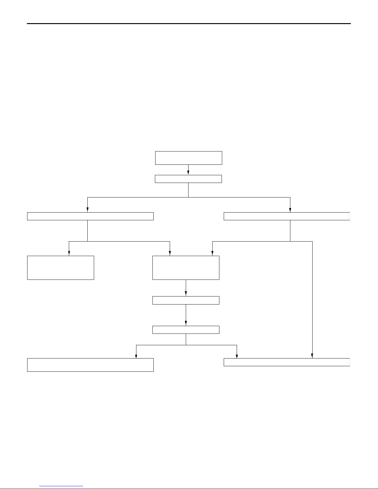
1. STANDARD FLOW OF DIAGNOSIS TROUBLESHOOTING
The troubleshooting sections follow the basic diagnosis flow which is given below. If the diagnosis
flow is different from that given below, or if additional explanation is required, the details of such
differences or additions will also be listed.
Diagnosis method
Gathering information
from the customer.
Check trouble symptom.
Reoccurs Does not reoccur.
Read the diagnosis code
No diagnosis code
or communication
with MUT-II not
possible
Refer to the INSPECTION
CHART FOR TROUBLE
SYMPTOMS (Refer to
applicable group.)
Diagnosis code
displayed.
Refer to the INSPECTION CHART FOR DIAGNOSIS
CODES (Refer to applicable group.)
Diagnosis code
displayed.
After taking note of the
malfunction code, erase
the diagnosis code
memory
Recheck trouble symptom.
Read the diagnosis codes.
Read the diagnosis code
Diagnosis code
displayed.
No diagnosis
code
INTERMITTENT MALFUNCTIONS (Refer to P.00-13.)
No diagnosis
code
2. SYSTEM OPERATION AND SYMPTOM VERIFICATION TESTS
If verification of the trouble symptoms is difficult, procedures for checking operation and verifying
trouble symptoms are shown.
3. DIAGNOSIS FUNCTION
Details which are different from those in the “Diagnosis Function” section on the next page are listed.
Page 9
GENERAL – How to Use Troubleshooting/Inspection Service Points
4. INSPECTION CHART FOR DIAGNOSIS CODES
5. INSPECTION PROCEDURE FOR DIAGNOSIS CODES
Indicates the inspection procedures corresponding to each diagnosis code. (Refer to P.00-10 for how
to read the inspection procedures.)
6. INSPECTION CHART FOR TROUBLE SYMPTOMS
If there are trouble symptoms even though the results of inspection using the MUT-II show that all
diagnosis codes are normal, inspection procedures for each trouble symptom will be found by means
of this chart.
7. INSPECTION PROCEDURE FOR TROUBLE SYMPTOM
Indicates the inspection procedures corresponding to each trouble symptoms classified in the Inspection
Chart for Trouble Symptoms. (Refer to P.00-10 for how to read the inspection procedures.)
8. SERVICE DATA REFERENCE TABLE
Inspection items and normal judgement values have been provided in this chart as reference information.
9. CHECK AT ECU TERMINALS
Terminal numbers for the ECU connectors, inspection items and standard values have been provided
in this chart as reference information.
00-7
10. INSPECTION PROCEDURES USING AN OSCILLOSCOPE
When there are inspection procedures using an oscilloscope, these are listed here.
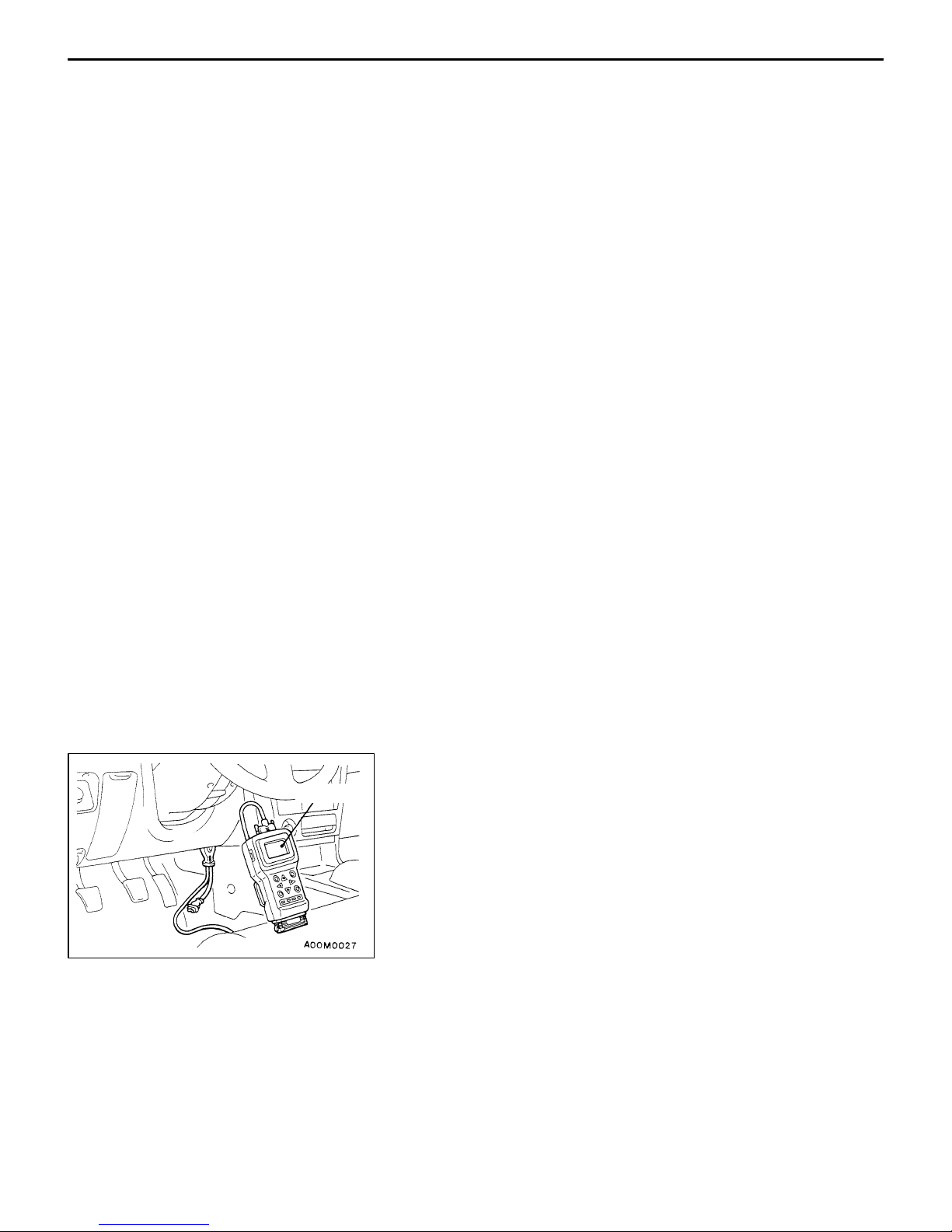
DIAGNOSIS FUNCTION
MUT-II
METHOD OF READING DIAGNOSIS CODES
WHEN USING THE MUT-II
Connect the MUT-II to the diagnosis connector and take a
reading of the diagnosis codes.
Caution
Turn off the ignition switch before connecting or
disconnecting the MUT-II.
Page 10
00-8
GENERAL – How to Use Troubleshooting/Inspection Service Points
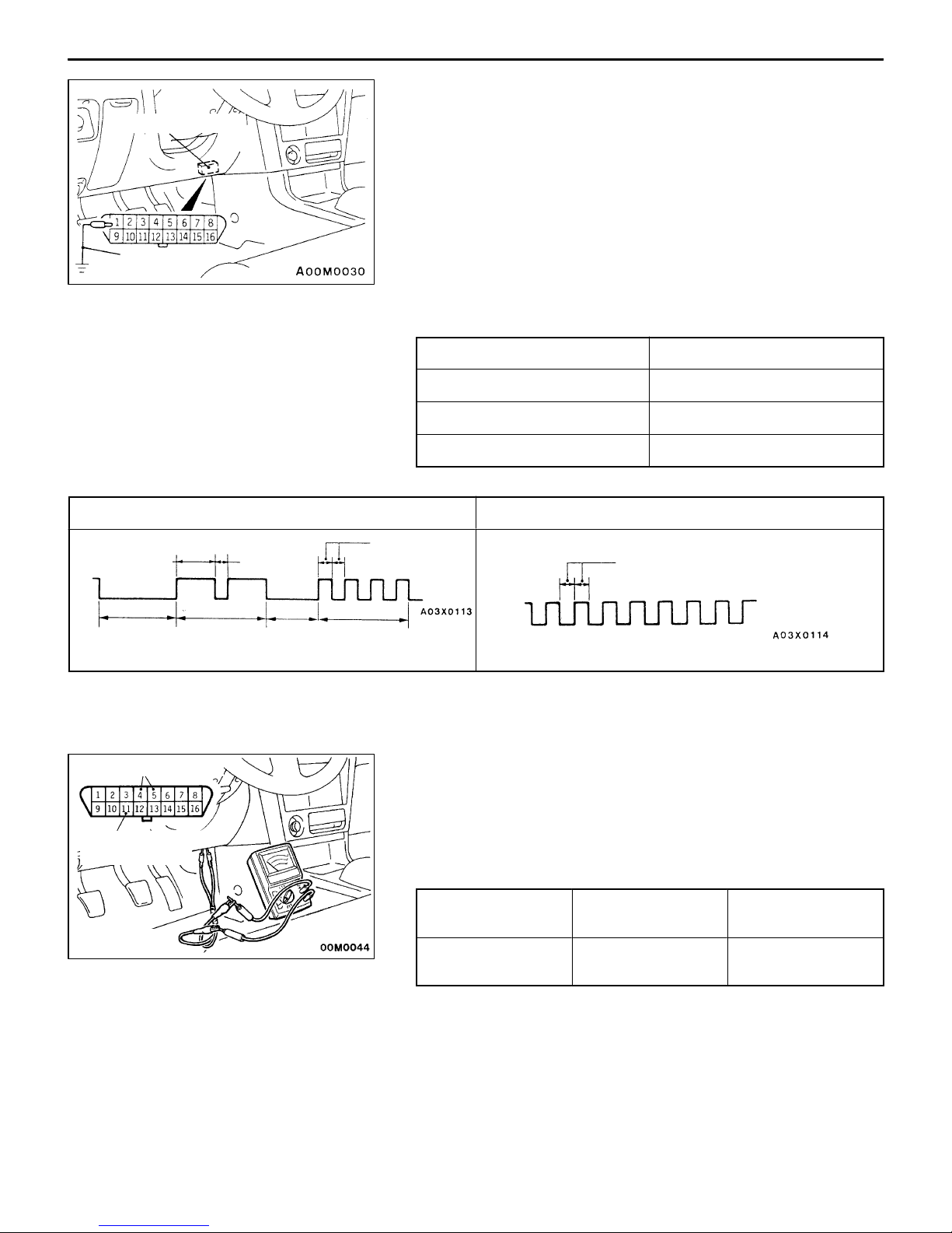
WHEN USING THE WARNING LAMP
Diagnosis connector
1. Use the special tool to earth No.1 terminal (diagnosis
control terminal) of the diagnosis connector.
2. To check ABS system, remove the valve relay.
NOTE
That is because the valve relay is off and the warning
lamp remains illuminated if there is a fault in the ABS
system.
MB991529
3. Turn on the ignition switch.
4. Read out a diagnosis code by observing how the warning
lamp flashes.
Applicable systems
System name Warning lamp name
MPI Engine warning lamp
AYC A YC warning lamp
ABS ABS warning lamp
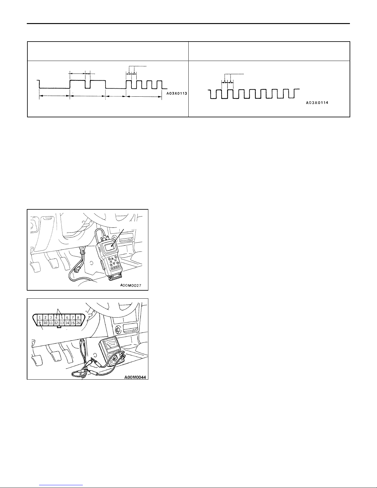
Indication of diagnosis code by warning lamp
When the diagnosis code No.24 is output When no diagnosis code is output*
On
Off
1.5 secs.
Pause
time 3
secs.
Tens
signal
0.5 sec.
Place
division
2 secs.
Units
signal
0.5 sec.
On
Off
0.5 sec.
NOTE
*: Even if the ABS system is normal, removing the valve relay causes the diagnosis code No.52 to
be output.
Earth terminal
WHEN USING THE VOLTMETER
Use the special tool to connect the diagnosis output terminals
and the earth terminal of the diagnosis connector to a voltmeter
and take a reading of the diagnosis codes from the movement
Full-auto air conditioner terminal
of the needle.
Voltmeter connection terminals
MB991529
System name Positive connection
terminal
Full-auto air
conditioner
11 4 or 5
Negative connection terminal
Page 11
GENERAL – How to Use Troubleshooting/Inspection Service Points
Diagnosis result display method when using a voltmeter
00-9
Example of diagnosis code voltage wave pattern for
diagnosis code No. 24
0.5 sec.
Units
signal
12V
0 V
1.5 secs.
Pause
time 3
secs.
Tens
signal
0.5 sec.
Place
division
2 secs.
Normal voltage wave pattern
0.5 sec.
12 V
0 V
METHOD OF ERASING DIAGNOSIS CODES
WHEN USING THE MUT-II
Connect the MUT-II to the diagnosis connector and erase the diagnosis code.
Caution
Turn off the ignition switch before connecting or disconnecting the MUT-II.
WHEN NOT USING THE MUT-II
(1) Turn the ignition switch to OFF.
(2) After disconnecting the battery cable from the battery (–) terminal for 10 seconds or more, reconnect
the cable.
(3) After the engine has warmed up, run it at idle for about 15 minutes.
INPUT SIGNAL INSPECTION POINTS <VEHICLES
MUT-II
WITH ETACS-ECU>
WHEN USING THE MUT-II
1. Connect the MUT-II to the diagnosis connector.
Earth terminal
ET ACS terminal
MB991529
Caution
The MUT-II should be connected or disconnected after
turning the ignition switch to the OFF position.
2. If buzzer of the MUT-II sounds once when the each switch
is operated (ON/OFF), the ETACS-ECU input signal for
that switch circuit system is normal.
WHEN USING VOLTMETER
1. Use the special tool to connect a voltmeter between
the earth terminal (No. 4 or 5) and the ETACS terminal
(No. 9) of the diagnosis connector.
2. If the voltmeter indicator deflects once when the each
switch is operated (ON/OFF), the ETACS-ECU input signal
for that switch circuit system is normal.
Page 12

00-10
GENERAL – How to Use Troubleshooting/Inspection Service Points
HOW TO USE THE INSPECTION PROCEDURES
The causes of a high frequency of problems occurring in electronic circuitry are generally the connectors,
components, the ECU and the harnesses between connectors, in that order. These inspection procedures
follow this order, and they first try to discover a problem with a connector or a defective component.
1. Comments on the diagnosis code or trouble
CHECKING PROCEDURE 4
symptom above.
D Indicator does not turn on or off even if control
mode switch is pressed.
D Indicator switch should not be illuminated is
illuminated.
In the above cases, the ECS switch circuit is defective or the indicator
circuit is defective.
MUT-II Data list
17 Control mode selection switch
OK: Voltage changes between approx. 0V → approx.
2.5V → approx. 5V when the switch is operated.
NG
ECU switch component inspection (Refer to P.3-44.)
OK
Measure at switch connector A-44
D Disconnect the connector, and measure at the harness
side.
D Voltage between terminal 6 – earth and terminal 8 –
earth
OK: Approx. 5V
OK
Check the following connector. A-44
OK
Check trouble symptom.
Replace the ECS-ECU.
OK
4. Indicates voltage and resistance to be measured at a particular
NG
OK
NG
5. Inspect the contact condition at each connector terminal.
Probable cause
2. Indicates inspection carried out using the
MUT-II.
Indicates the operation and inspection procedures.
Indicates the OK judgement conditions.
3. Detailed inspection procedures (methods)
such as component inspection and circuit
inspection are listed on a separate page, and
are given here for reference.
connector.
(Refer to Connector Measurement Service Points.)
The connector position can be located in the wiring diagram in the
electrical wiring manual by means of this symbol.
Indicates operation and inspection procedures, inspection terminals
and inspection conditions.
Indicates the OK judgement conditions.
Repair
(Refer to Connector Inspection Service Points.)
The connector position can be located in the wiring diagram in the
electrical wiring manual by means of this symbol.
Caution
After carrying out connector inspection, always be sure to
reconnect the connector as it was before.
HARNESS INSPECTION
Check for an open or short circuit in the harness between the terminals which were defective according
to the connector measurements. Carry out this inspection while referring to the electrical wiring manual.
Here, “Check harness between power supply and terminal xx” also includes checking for blown fuses.
For inspection service points when there is a blown fuse, refer to “Inspection Service Points for a Blown
Fuse.”
MEASURES TO TAKE AFTER REPLACING THE ECU
If the trouble symptoms have not disappeared even after replacing the ECU, repeat the inspection procedure
from the beginning.
6. Confirm that there are trouble symptoms. If trouble symptoms have
disappeared, the connector may have been inserted incorrectly and the
trouble symptom may have disappeared during inspection.
If it seems that trouble symptoms still remain, proceed to the next page of
instructions.
7. If trouble symptoms still remain up to this stage, there is a possibility that there is an
open or short circuit in the harness between the connectors, so check the harness.
Alternatively , the cause may be a defective ECU, so try replacing the ECU and check
if the trouble symptom disappears.
Page 13

GENERAL – How to Use Troubleshooting/Inspection Service Points
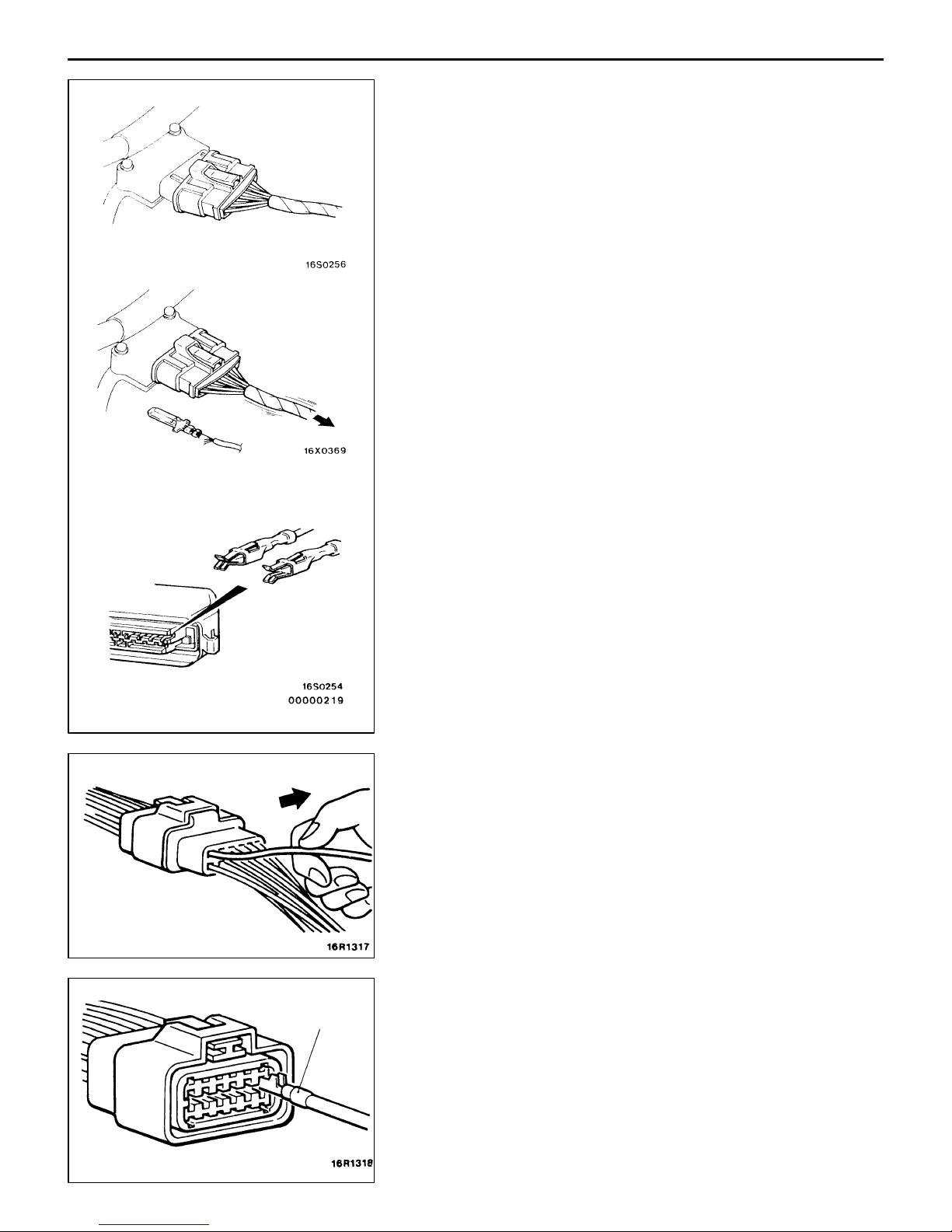
CONNECTOR MEASUREMENT SER VICE POINTS
Turn the ignition switch to OFF when connecting disconnecting
the connectors, and turn the ignition switch to ON when
measuring if there are no instructions to be contrary.
00-11
Extra-thin probe
Test bar
Connector
Inspection harness
for connector pin
contact pressure
Harness connector
IF INSPECTING WITH THE CONNECTOR CONNECTED
(WITH CIRCUIT IN A CONDITION OF CONTINUITY)
Waterproof Connectors
Be sure to use the special tool (harness connector). Never
insert a test bar from the harness side, because to do so
will reduce the waterproof performance and result in corrosion.
Ordinary (non-waterproof) Connectors
Check by inserting the test bar from the harness side. Note
that if the connector (control unit, etc.) is too small to permit
insertion of the test bar, it should not be forced; use a special
tool (the extra-thin probe in the harness set for checking
for this purpose.
IF INSPECTING WITH THE CONNECTOR DISCONNECTED
<When Inspecting a Female Pin>
Use the special tool (inspection harness for connector pin
contact pressure in the harness set for inspection).
The inspection harness for connector pin contact pressure
should be used. the test bar should never be forcibly inserted,
as it may cause a defective contact.
<When Inspecting a Male Pin>
Touch the pin directly with the test bar.
Caution
At this time, be careful not to short the connector pins
with the test bars. To do so may damage the circuits
inside the ECU.
Page 14
00-12
GENERAL – How to Use Troubleshooting/Inspection Service Points
Connector disconnected or improperly
connected
Defective connector contact
Harness wire breakage
at terminal section
Low contact pressure
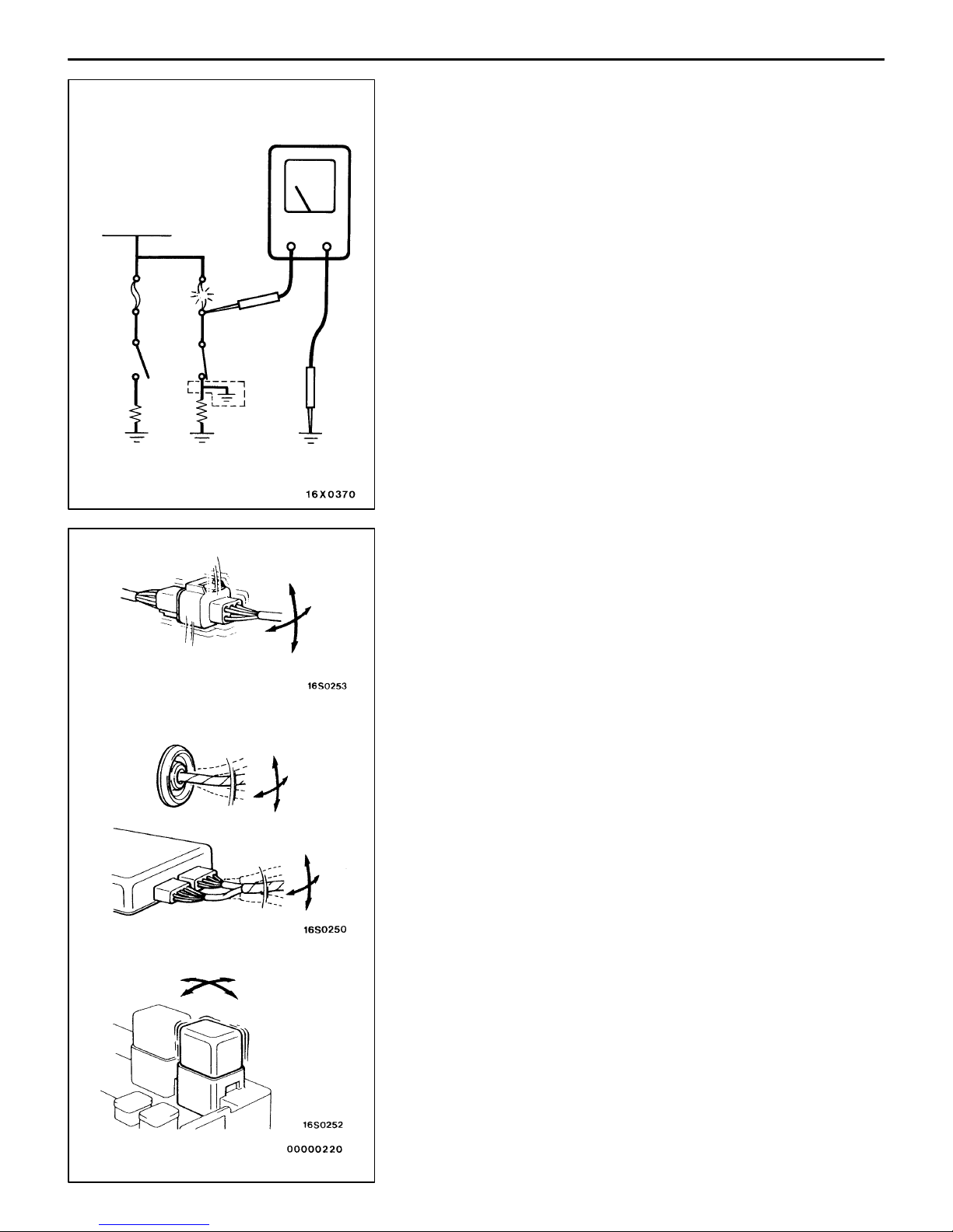
CONNECTOR INSPECTION
VISUAL INSPECTION
D Connector is disconnected or improperly connected
D Connector pins are pulled out
D Due to harness tension at terminal section
D Low contact pressure between male and female terminals
D Low connection pressure due to rusted terminals or foreign
matter lodged in terminals
MB991219
CONNECTOR PIN INSPECTION
If the connector pin stopper is damaged, the terminal
connections (male and female pins) will not be perfect even
if the connector body is connected, and the pins may pull
out of the reverse side of the connector. Therefore, gently
pull the harnesses one by one to make sure that no pins
pull out of the connector.
CONNECTOR ENGAGEMENT INSPECTION
Use the special tool (connector pin connection pressure
inspection harness of the inspection harness set) to inspect
the engagement of the male pins and females pins. (Pin
drawing force : 1 N or more)
Page 15
GENERAL – How to Use Troubleshooting/Inspection Service Points
INSPECTION SERVICE POINTS FOR A BLOWN
FUSE
Remove the fuse and measure the resistance between the
load side of the fuse and the earth. Set the switches of all
0 Ω
Battery
circuits which are connected to this fuse to a condition of
continuity. If the resistance is almost 0 Ω at this time, there
is a short somewhere between these switches and the load.
If the resistance is not 0 Ω, there is no short at the present
time, but a momentary short has probably caused the fuse
to blow.
00-13
Fuse
Load
switch
Load
Connector
inspection
The main causes of a short circuit are the following.
D Harness being clamped by the vehicle body
D Damage to the outer casing of the harness due to wear
or heat
D Water getting into the connector or circuitry
D Human error (mistakenly shorting a circuit, etc.)
POINTS TO NOTE FOR INTERMITTENT
MALFUNCTIONS
Intermittent malfunctions often occur under certain conditions,
and if these conditions can be ascertained, determining the
cause becomes simple. In order to ascertain the conditions
under which an intermittent malfunction occurs, first ask the
customer for details about the driving conditions, weather
conditions, frequency of occurrence and trouble symptoms,
and then try to recreate the trouble symptoms. Next, ascertain
whether the reason why the trouble symptom occurred under
these conditions is due to vibration, temperature or some
other factor. If vibration is thought to be the cause, carry
out the following checks with the connectors and components
to confirm whether the trouble symptom occurs.
The objects to be checked are connectors and components
which are indicated by inspection procedures or given as
probable causes (which generates diagnosis codes or trouble
symptoms.)
D Gently shake the connector up, down and to the left and
right.
D Gently shake the wiring harness up, down and to the
left and right.
D Gently rock each sensor and relay, etc. by hand.
D Gently shake the wiring harness at suspensions and other
moving parts.
NOTE
If determining the cause is difficult, the flight recorder function
of the MUT-II can also be used.
Page 16

00-14
16 valves-intercooler
(4WD-5M/T)
controlled fuel
16
(4WD-5M/T)
turbo)
MODELS
<LANCER EVOLUTION-IV>
GENERAL – Models
Model
code
E-CN9A SNDF ’97 RS 4G63 (2,000-DOHC –-W5M51
Class
code
SRGF ’97 GSR
Model
year
Grade Engine model Transmission
model
turbo)
Applicable serial numbers
E-CN9A: CN9A – 0000001 Y
<LANCER EVOLUTION-V>
Model
code
GF-CP9A SNDF ’98 EVOLUTION-V RS 4G63 (2,000-DOHC –
Class
code
SNGF ’98 EVOLUTION-V
Model
year
Grade Engine model Transmission
GSR
model
W5M51
valves-intercooler
turbo)
Applicable serial numbers
GF-CP9A: CP9A – 0000001 Y
<LANCER EVOLUTION-VI>
Model
code
Class
code
Model
year
Grade Engine model Transmission
model
Fuel supply
system
Electronically
injection (MPI)
Fuel supply
system
MPI
Fuel supply
system
f
GF-CP9A SNDF ’99 EVOLUTION-VI
RS
SNGF ’99 EVOLUTION-VI
GSR
Applicable serial numbers
GF-CP9A: CP9A – 0100001 Y
4G63 (2,000-DOHC –
16 valves-intercooler
W5M51
(4WD-5M/T)
MPI
Page 17

GENERAL – Precautions Before Service
00-15
PRECAUTIONS BEFORE SERVICE
SUPPLEMENTAL RESTRAINT SYSTEM (SRS)
1. Items to follow when servicing SRS
(1) Be sure to read GROUP 52B – Supplemental Restraint System (SRS).
For safe operations, please follow the directions and heed all warnings.
(2) Always use the designated special tools and test equipment.
(3) Wait at least 60 seconds after disconnecting the battery cable before doing any further work.
The SRS system is designed to retain enough voltage to deploy the air bag even after the battery
has been disconnected. Serious injury may result from unintended air bag deployment if work
is done on the SRS system immediately after the battery cable is disconnected.
(4) Never attempt to disassemble or repair the SRS components. (SRS air bag control unit, air bag
module and clock spring.) If faulty, replace it.
(5) Warnings labels must be needed when servicing and handling SRS components. Warning labels
are located in the following locations.
D Sun visor
D Glove box
D SRS air bag control unit
D Steering wheel
D Steering gear and linkage
D Air bag module
D Clock spring
(6) Store components removed from the SRS in a clean and dry place.
The air bag module should be stored on a flat surface and placed so that the pad surface is
facing upwards.
(7) Be sure to deploy the air bag before disposing of air bag module or disposing of a vehicle equipped
with an air bag. (Refer to GROUP 52B – Air Bag Module Disposal Procedures.)
(8) Whenever you finish servicing the SRS, check the SRS warning lamp operation to make sure
that the system functions properly.
2. Observe the following when carrying out operations on place where SRS components are installed,
including operations not directly related to the SRS air bag.
(1) When removing or installing parts do not allow any impact or shock to the SRS components.
(2) SRS components should not be subjected to heat over 93_C, so remove the SRS components
before drying or baking the vehicle after painting.
After re-installing them, check the SRS warning lamp operation to make sure that the system
functions properly.
Page 18
00-16
GENERAL – Precautions Before Service
SERVICING THE ELECTRICAL SYSTEM
Before replacing a component related to the electrical system
and before undertaking any repair procedures involving the
electrical system, be sure to first disconnect the negative
(–) cable from the battery in order to avoid damage caused
by short-circuiting.
Caution
Before connecting or disconnecting the negative (–) cable,
be sure to turn off the ignition switch and the lighting
switch.
(If this is not done, there is the possibility of
semiconductor parts being damaged.)
APPLICATION OF ANTI-CORROSION AGENTS
AND UNDERCOATS
If oil or grease gets onto the oxygen sensor, it will cause
a drop in the performance of the sensor.
Cover the oxygen sensor with a protective cover when applying
anti-corrosion agents and undercoats.
Approx.
40 cm
PRE-INSPECTION CONDITION
“Pre-inspection condition” refers to the condition that the
vehicle must be in before proper engine inspection can be
carried out. If you see the words “Set the vehicle to the
pre-inspection condition.” in this manual, it means to set the
vehicle to the following condition.
D Engine coolant temperature: 80–90_C
D Lamps, electric cooling fan and all accessories: OFF
D M/T: Neutral
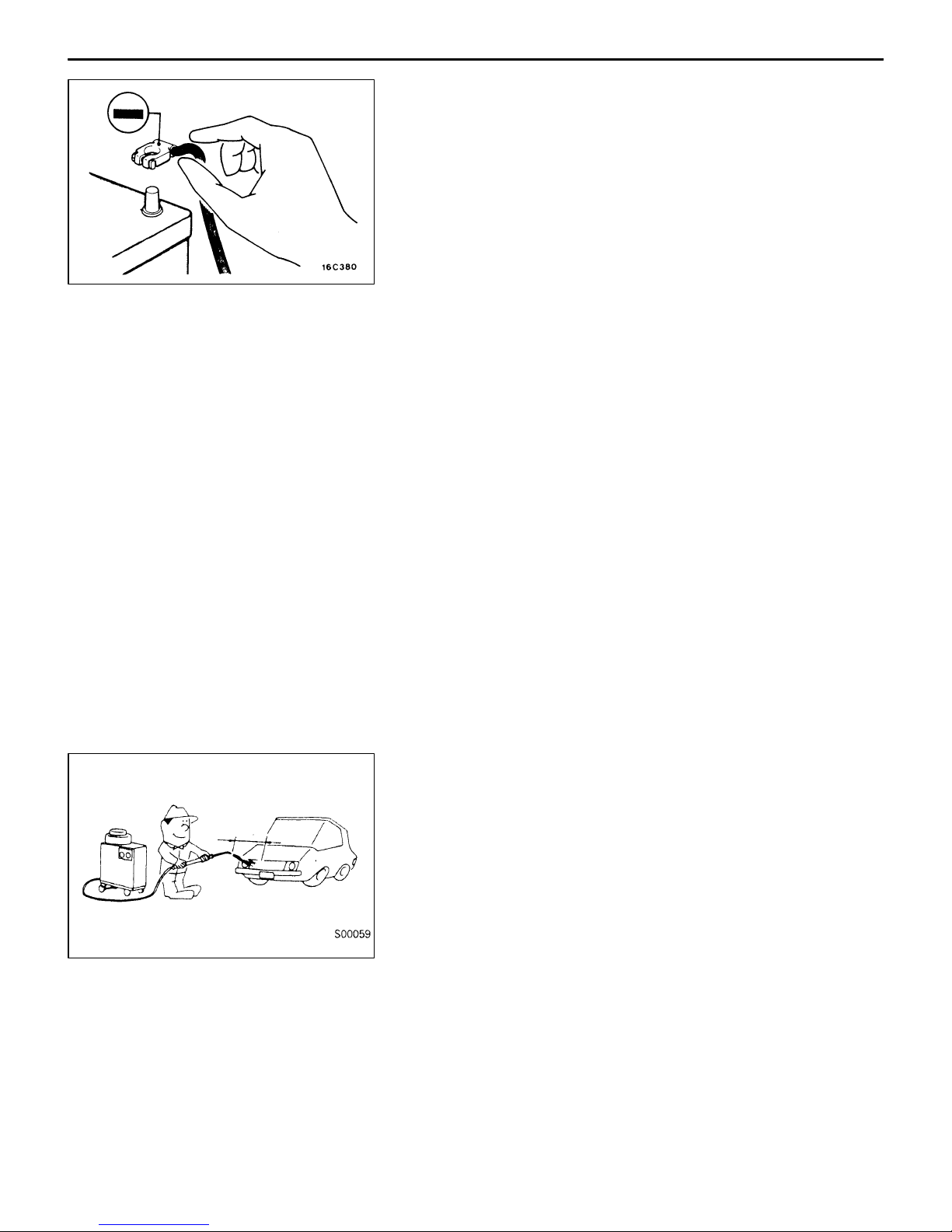
VEHICLE WASHING
If high-pressure car-washing equipment or steam car-washing
equipment is used to wash the vehicle, be sure to note the
following information in order to avoid damage to plastic
components, etc.
D Spray nozzle distance: Approx. 40 cm or more
D Spray pressure: 3,900 kPa or less
D Spray temperature: 82_C or less
D Time of concentrated spray to one point: within 30 sec.
Page 19
GENERAL – Precautions Before Service
00-17
MUT-II
sub-assembly
ROM pack
MUT-II
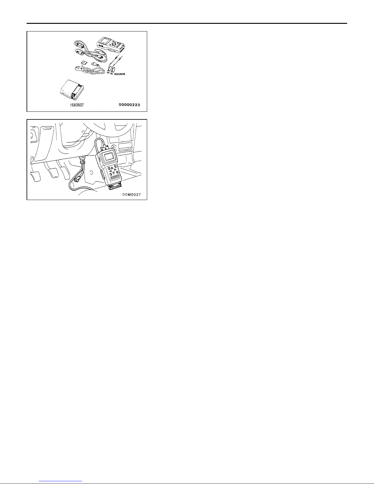
Refer to the MUT-II INSTRUCTION MANUAL for instructions
on handling the MUT-II.
Connect the MUT-II to the diagnosis connector as shown
in the illustration.
Caution
Connection and disconnection of the MUT-II should
always be made with the ignition switch in the OFF
position.
Page 20
00-18
GENERAL – Support Locations for Lifting and Jacking
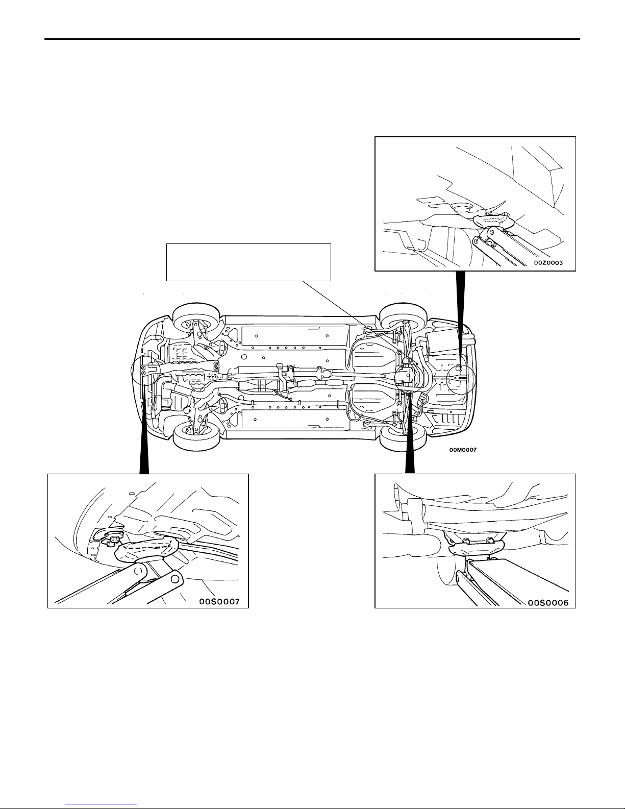
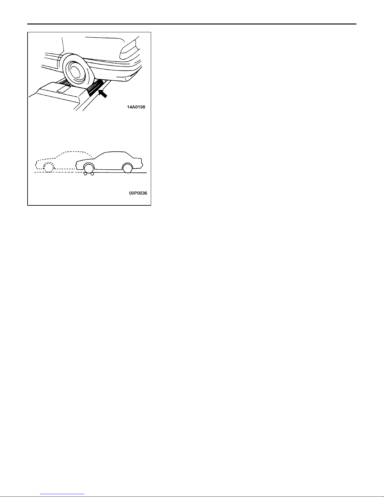
SUPPORT LOCATIONS FOR LIFTING AND JACKING
GARAGE JACK
Caution
Do not support the vehicles at locations other than specified supporting points. Neglecting this
will cause damage, etc.
Caution
Never support the rear floor
crossmember.
Page 21
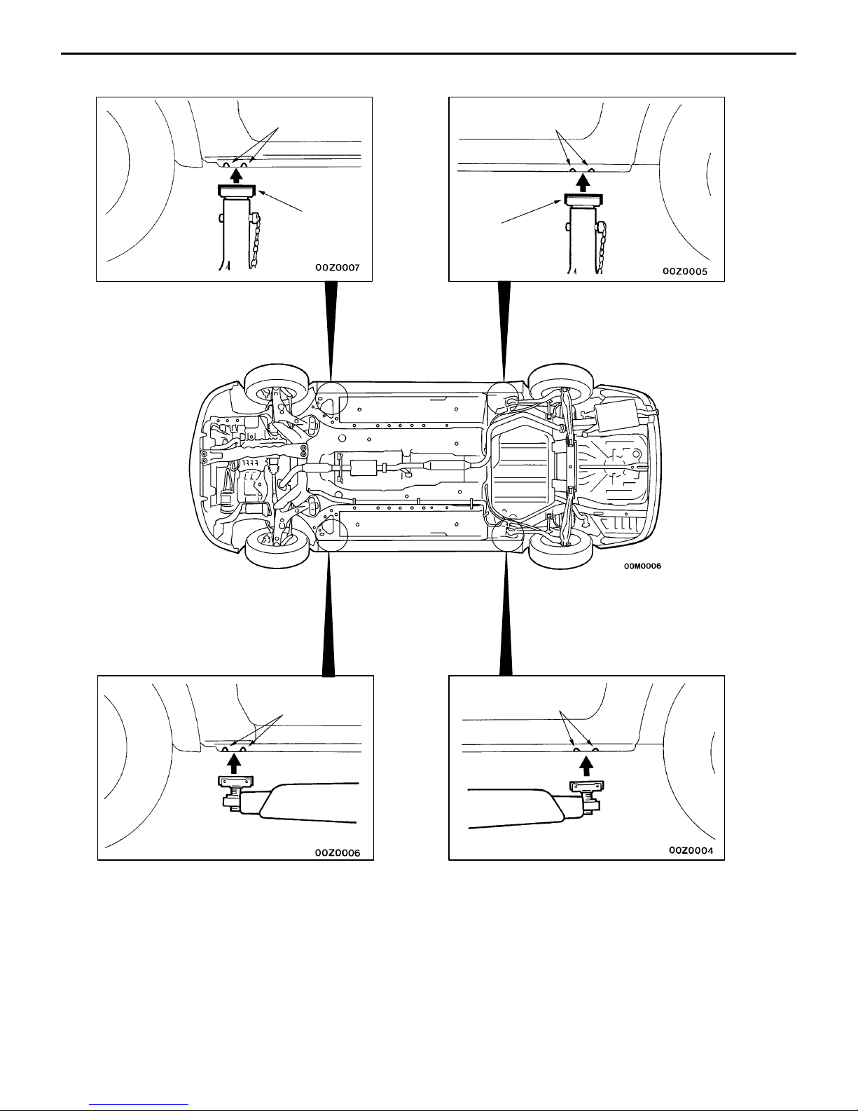
AXLE STANDS
GENERAL – Support Locations for Lifting and Jacking
00-19
Notch
Rubber
Notch
Rubber
SINGLE-POST AND
DOUBLE-POST LIFT
Notch
Notch
Page 22
00-20
GENERAL – Special Handling Instruments for Towing
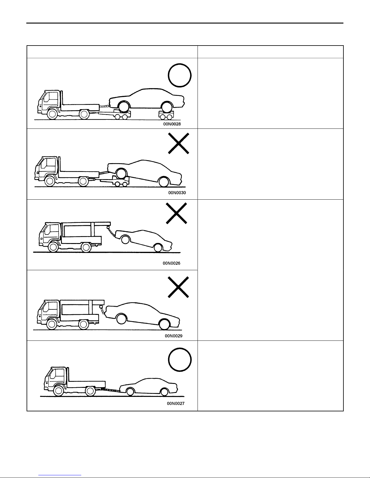
SPECIAL HANDLING INSTRUMENTS FOR TOWING
Towing methods Remarks
If a tow truck is used
Lifting method for 4 wheels – Good
Front wheels lifted – No good
Front wheels lifted – No good
D For 4WD models, the basic principle is that all
four wheels are to be raised before towing.
D The shift lever should be set to 1st gear and
the parking brake should be applied.
D The vehicle must not be towed by placing only
its front wheels or only the rear wheels on a
rolling dolly, because to do so will result in
deterioration of the viscous coupling and result
in the viscous coupling causing the vehicle to
jump forward suddenly.
D If only the front wheels or only the rear wheels
are lifted for towing, the bumper will be damaged.
In addition, lifting of the rear wheels causes
the oil to flow forward, and may result in heat
damage to the rear bushing of the transfer, and
so should never be done.
Rear wheels lifted – No good
Towing by rope or cable – Good
D The front and rear wheels must rotate normally.
D Both running and driving systems must function
normally.
D The shift lever must be set to the neutral position
and the ignition key must be set to “ACC”.
Page 23
Brake tester
GENERAL – Brake Test
BRAKE TEST
In order to stabilize the viscous coupling’s dragging force,
the brake test should always be conducted after the
speedometer test.
FRONT WHEEL MEASUREMENTS
1. Place the front wheels on the brake tester.
2. Perform the brake test.
Caution
The rear wheels should remain on the ground.
3. If the brake dragging force exceeds the specified value,
jack up the vehicle and manually rotate each wheel to
check the rotation condition of each wheel.
NOTE
If the brake dragging force exceeds the specified value,
the cause may be the effect of the viscous coupling’s
dragging force, so jack up the front wheels and check
the rotation condition of the wheels in this state for no
effect by the viscous coupling’s dragging force.
REAR WHEEL MEASUREMENTS
After placing the rear wheels on the brake tester, follow the
same procedures as for the front wheel measurements.
00-21
Page 24

00-22
GENERAL – Tightening Torque
TIGHTENING TORQUE
Each torque value in the table is a standard value
for tightening under the following conditions.
(1) Bolts, nuts and washers are all made of steel
and plated with zinc.
(2) The threads and bearing surface of bolts and
nuts are all in dry condition.
The values in the table are not applicable:
(1) If toothed washers are inserted.
(2) If plastic parts are fastened.
(3) If bolts are tightened to plastic or die-cast
inserted nuts.
(4) If self-tapping screws or self-locking nuts are
used.
Standard bolt and nut tightening torque
Thread size Torque Nm
Bolt nominal
diameter (mm)
M5 0.8 2.5 4.9 5.9
M6 1.0 4.9 8.8 9.8
M8 1.25 12 22 25
M10 1.25 24 44 52
M12 1.25 41 81 96
M14 1.5 72 137 157
Pitch (mm) Head mark “4” Head mark “7” Head mark “8”
M16 1.5 111 206 235
M18 1.5 167 304 343
M20 1.5 226 412 481
M22 1.5 304 559 647
M24 1.5 392 735 853
Flange bolt and nut tightening torque
Thread size Torque Nm
Bolt nominal
diameter (mm)
M6 1.0 4.9 9.8 12
M8 1.25 13 24 28
M10 1.25 26 49 57
M10 1.5 24 44 54
M12 1.25 46 93 103
M12 1.75 42 81 96
Pitch (mm) Head mark “4” Head mark “7” Head mark “8”
Page 25

ENGINE
CONTENTS
11-1
GENERAL INFORMATION 2. . . . . . . . . . . . . . . .
SPECIFICATIONS 3. . . . . . . . . . . . . . . . . . . . . . . .
Service Specifications 3. . . . . . . . . . . . . . . . . . . . . .
Torque Specifications 5. . . . . . . . . . . . . . . . . . . . . .
New Tightening Method by Use of Bolts
to Be Tightened in Plastic Area 9. . . . . . . . . . . .
Sealants 9. . . . . . . . . . . . . . . . . . . . . . . . . . . . . . . . . .
Form-In-Place Gasket 10. . . . . . . . . . . . . . . . . . . .
SPECIAL TOOLS 11. . . . . . . . . . . . . . . . . . . . . . .
ALTERNATOR AND IGNITION SYSTEM 14.
TIMING BELT 15. . . . . . . . . . . . . . . . . . . . . . . . .
FUEL AND EMISSION CONTROL PARTS 27
SECONDARY AIR SYSTEM AND INTAKE
MANIFOLD 29. . . . . . . . . . . . . . . . . . . . . . . . . . . .
EXHAUST MANIFOLD 31. . . . . . . . . . . . . . . . .
WATER PUMP AND WATER HOSE 34. . . . .
ROCKER ARMS AND CAMSHAFT 37. . . . . .
CYLINDER HEAD AND VALVES 43. . . . . . . .
FRONT CASE, COUNTERBALANCE
SHAFT AND OIL PAN 51. . . . . . . . . . . . . . . . .
PISTON AND CONNECTING ROD 59. . . . . .
CRANKSHAFT AND FLYWHEEL 67. . . . . . . .
THROTTLE BODY 73. . . . . . . . . . . . . . . . . . . . .
TURBOCHARGER 75. . . . . . . . . . . . . . . . . . . . .
ALTERNATOR 79. . . . . . . . . . . . . . . . . . . . . . . . .
STARTER MOTOR 83. . . . . . . . . . . . . . . . . . . . .
Page 26

11-2
ENGINE – General Information
GENERAL INFORMATION
Descriptions Specifications
Type In-line OHV, SOHC
Number of cylinders 4
Combustion chamber Pentroof + curved top piston type
Total displacement dm
Cylinder bore mm 85.0
Piston stroke mm 88.0
Compression ratio 8.8
V alve timing Intake valve Opens (BTDC) 21°
Lubrication system Pressure feed, full-flow filtration
Oil pump type Involute gear type
3
Closes (ABDC) 59°
Exhaust valve Opens (BBDC) 58°
Closes (ATDC) 18°
1,997
Page 27

ENGINE – Specifications
hol
SPECIFICATIONS
SERVICE SPECIFICATIONS
Items Standard value Limit
Timing belt
Auto-tensioner rod projection length mm 12 –
11-3
Auto-tensioner rod pushed-in amount [when pushed with a force of 98
– 196 N] mm
Rocker arms and camshaft
Camshaft cam height mm Intake 35.79 35.29
Exhaust 35.49 34.99
Camshaft journal outer diameter mm 26 –
Cylinder head and valves
Cylinder head flatness of gasket surface mm Less than 0.05 0.2
Cylinder head grinding limit of gasket surface mm
Total resurfacing depth of both cylinder head and cylinder block
Cylinder head overall height mm 131.9 – 132.1 –
Cylinder head bolt shank length mm – Maximum 99.4
V alve thickness of valve head (margin) mm Intake 1.0 0.5
Exhaust 1.5 1.0
Overall valve length mm Intake 109.5 109.0
Exhaust 109.7 109.2
1.0 or less –
– 0.2
Valve thickness to valve guide clearance
mm
V alve face angle 45° – 45.5° –
Valve spring free length mm 48.3 47.3
Valve spring load/installed height N/mm 294/40.0 –
Valve spring out-of-squareness 1.5° or less Maximum 4°
Valve seat contact width mm 0.9 – 1.3 –
Valve guide inner diameter mm 6.6 –
Valve guide projection from cylinder head upper surface mm 20.5 –
Valve stem projection mm Intake 49.20 49.70
Oversize rework dimensions of valve guide
e mm
Intake 0.02 – 0.05 0.10
Exhaust 0.05 – 0.09 0.15
Exhaust 48.40 48.90
0.05 O.S. 12.05 – 12.07 –
0.25 O.S. 12.25 – 11.27 –
0.50 O.S. 12.50 – 12.52 –
Page 28

11-4
Items LimitStandard value
ENGINE – Specifications
Intake oversize rework dimensions of valve
guide hole mm
Exhaust oversize rework dimensions of
valve guide hole mm
Front case and oil pan
Oil pump side clearance mm Drive gear 0.08 – 0.14 –
Oil pressure at curb idle speed kPa [Oil temperature is 75 to 90°C] 78 or more –
Piston and connecting rod
Piston outer diameter mm 85.0 –
Piston ring side clearance mm No. 1 ring 0.04 – 0.075 –
Piston ring end gap mm No. 1 ring 0.25 – 0.35 0.8
0.3 O.S. 35.30 – 35.33 –
0.6 O.S. 35.60 – 35.63 –
0.3 O.S. 33.30 – 33.33 –
0.6 O.S. 33.60 – 33.63 –
Driven gear 0.06 – 0.12 –
No. 2 ring 0.02 – 0.06 –
No. 2 ring 0.40 – 0.55 0.8
Oil ring 0.10 – 0.40 1.0
Piston pin outer diameter mm 21.0 –
Piston pin press-in load N (Room temperature) 7,350 – 17,200 –
Crankshaft pin oil clearance mm 0.02 – 0.05 0.1
Connecting rod big end side clearance mm 0.10 – 0.25 0.4
Crankshaft and flywheel
Crankshaft end play mm 0.05 – 0.25 0.40
Crankshaft journal outer diameter mm 57.0 –
Crankshaft pin outer diameter mm 44.0 –
Crankshaft journal oil clearance mm 0.02 – 0.04 0.1
Bearing cap bolt shank length mm – Maximum 71.1
Piston to cylinder clearance mm 0.02 – 0.04 –
Cylinder block grinding limit of gasket surface mm
Total resurfacing depth of both cylinder head and cylinder block
Cylinder block overall height mm 284 –
Cylinder block inner diameter mm 85.0 –
– 0.2
Cylinder block cylinder mm 0.01 –
Turbocharger
Waste gate actuator operation check kPa 100 113.3
Page 29

ENGINE – Specifications
Items LimitStandard value
Alternator
Rotor coil resistance Ω Approx. 3 – 5 –
Protrusion length of brush mm – 2
Starter motor
Commutator runout mm 0.05 0.1
Commutator outer diameter mm 32.0 31.4
Commutator undercut mm 0.5 –
TORQUE SPECIFICATIONS
Items Nm
Alternator and ignition system
Oil level gauge guide 13
11-5
Water pump pulley 9
Alternator brace (Alternator side) 21
Alternator brace (Tightened with water pump) 23
Alternator pivot bolt 44
Crankshaft pulley 25
Center cover 3
Spark plug 25
Ignition coil 10
Timing belt
Timing belt cover (Flange bolt) 11
Timing belt cover (Washer bolt) 9
Power steering pump bracket 49
Tensioner pulley 49
Tensioner arm 24
Auto tensioner 24
Idler pulley 48
Crank angle sensor 9
Oil pump sprocket 54
Camshaft bolt 118
Tensioner “B” 19
Counterbalance shaft sprocket 45
Page 30

11-6
Items Nm
Rocker cover 3.5
Engine support bracket 49
Camshaft sprocket bolt 88
Timing belt rear right cover 11
Timing belt rear left upper cover 11
Fuel and emission control parts
Throttle body 18
Fuel pressure regulator 9
Delivery pipe 11
Vacuum tank bracket 9
Solenoid valve bracket 9
Solenoid valve 9
ENGINE – Specifications
Vacuum hose and vacuum pipe 11
Secondary air intake manifold
Heat protector 13
Vacuum hose and vacuum pipe 11
Air pipe (Heat protector side) 13
Air pipe (Cam position sensor side) 11
Air pipe (Eye bolt) 49
Air pipe (Control valve side) 24
Air control valve 21
Air control valve bracket 24
Intake manifold stay 30
Intake manifold (M8) 19
Intake manifold (M10) 35
Exhaust manifold
Engine hanger 12
Heat protector (Turbocharger side) 14
Oxygen sensor 54
Exhaust fitting bolt 59
Exhaust fitting nut 59
Air outlet fitting 19
Page 31

ENGINE – Specifications
Items Nm
OIl return pipe (Turbocharger side) 9
Oil return pipe (Oil pan side – Head mark 7) 9
Oil return pipe (Oil pan side – Head mark 10) 13
Oil pipe 11
Oil pipe eye bolt (Cylinder head side) 16
Oil pipe eye bolt (Turbocharger side) 30
Water pipe 11
Water pipe eye bolt 41
Exhaust manifold (M8) 29
Exhaust manifold (M10) 49
Exhaust manifold (Turbocharger side) 59
Water pump and water hose
11-7
Water temperature sensor 29
Water temperature gauge unit 11
Water inlet fitting 24
Water outlet fitting (M6) 10
Water outlet fitting (M8) 13
Thermostat housing 24
Thermostat housing (Clamp) 11
Water inlet pipe (Cylinder block) 13
Water inlet pipe (Outlet fitting) 10
Water pump 14
Knock sensor 22
Rocker arms and camshaft
Camshaft position sensor 9
Camshaft position sensor cover 10
Camshaft position sensing cylinder 21
Camshaft position sensing support 13
Camshaft bearing cap 20
Oil delivery body 11
Cylinder head and valves
Cylinder head bolt [Tighten to 78 Nm and then completely before tightening to final torque
specification]
20 ! 90° + 90°
Page 32

11-8
Items Nm
Front case and oil pan
Drain plug 39
Oil pan 7
Oil screen 19
Buffle plate 22
Oil pressure switch 10
Oil cooler by-pass valve 54
Relief plug 44
Plug 24
Front case 24
Oil pump cover (Screw) 10
Oil pump cover (Bolt) 16
ENGINE – Specifications
Piston and connecting rods
Connecting rod nut 20 + 90° to 94°
Crankshaft and flywheel
Flywheel bolt 132
Rear plate 11
Bell housing cover 9
Oil seal case 11
Beam bearing cap bolt 25 + 90°
Check valve 32
Throttle body
Throttle position sensor 3.5
Idle speed control body assembly 3.5
Turbocharger
Waste gate actuator 11
Page 33

ENGINE – Specifications
11-9
NEW TIGHTENING METHOD – BY USE OF BOLTS TO BE TIGHTENED IN
PLASTIC AREA
A new type of bolts, to be tightened in plastic area, is currently used some parts of the engine. The
tightening method for the bolts is different from the conventional one. Be sure to observe the method
described in the text when tightening the bolts.
Service limits are provided for the bolts. Make sure that the service limits described in the text are strictly
observed.
D Areas where the bolts are in use:
(1) Cylinder head bolts
(2) Main bearing cap bolts
(3) Connecting rod cap bolts
D Tightening method
After tightening the bolts to the specified torque, tighten them another 90° or 180° (twice 90°). The
tightening method varies on different areas. Observe the tightening method described in the text.
SEALANTS
Item Specified sealant Quantity
Engine support bracket bolt 3MTM AAD Part No. 8672 or equivalent As required
Semi-circular packing 3MTM AAD Part No. 8672 or equivalent As required
Rocker cover 3MTM AAD Part No. 8672 or equivalent As required
Oil return pipe gasket 3MTM AAD Part No. 8731 or equivalent As required
Thermostat housing Mitsubishi Genuine Part No. MD970389 or
equivalent
Water outlet fitting Mitsubishi Genuine Part No. MD970389 or
equivalent
Engine coolant temperature gauge unit 3MTM AAD Part No. 8672 or equivalent As required
Engine coolant temperature sensor 3MTM AAD Part No. 8731 or equivalent As required
Cam position sensor support Mitsubishi Genuine Part No. MD970389 or
equivalent
Oil pressure switch 3MTM AAD Part No. 8672 or equivalent As required
Oil pan Mitsubishi Genuine Part No. MD970389 or
equivalent
Oil seal case Mitsubishi Genuine Part No. MD970389 or
equivalent
As required
As required
As required
As required
As required
Page 34

11-10
ENGINE – Specifications
FORM-IN-PLACE GASKET
The engine has several areas where the form-in-place gasket (FIPG) is in use. To ensure that the gasket
fully serves its purpose, it is necessary to observe some precautions when applying the gasket. Bead
size, continuity and location are of paramount importance. Too thin a bead could cause leaks. Too thick
a bead, on the other hand, could be squeezed out of location, causing blocking or narrowing of the
fluid feed line. To eliminate the possibility of leaks from a joint, therefore, it is absolutely necessary to
apply the gasket evenly without a break, while observing the correct bead size.
The FIPG used in the engine is a room temperature vulcanisation (RTV) type and is supplied in a 100-gram
tube (Part No. MD970389). Since the RTV hardens as it reacts with the moisture in the atmospheric
air, it is normally used in the metallic flange areas. The FIPG, Part No. MD970389, can be used for
sealing both engine oil and coolant, while Part No. MD997110 can only be used for engine oil sealing.
Disassembly
The parts assembled with the FIPG can be easily disassembled without use of a special method. In
some cases, however, the sealant between the joined surfaces may have to be broken by lightly striking
with a mallet or similar tool. A flat and thin gasket scraper may be lightly hammered in between the
joined surfaces. In this case, however, care must be taken to prevent damage to the joined surfaces.
For removal of the oil pan, the special tool “Oil Pan Remover” (MD998727) is available. Be sure to use
the special tool to remove the oil pan.
Surface Preparation
Thoroughly remove all substances deposited on the gasket application surfaces, using a gasket scraper
or wire brush. Check to ensure that the surfaces to which the FIPG is to be applied is flat. Make sure
that there are no oils, greases and foreign substances deposited on the application surfaces. Do not
forget to remove the old sealant remained in the bolt holes.
Form-in-Place Gasket Application
When assembling parts with the FIPG, you must observe some precautions, but the procedures is very
simple as in the case of a conventional precut gasket.
Applied FIPG bead should be of the specified size and without breaks. Also be sure to encircle the
bolt hole circumference with a completely continuous bead. The FIPG can be wiped away unless it is
hardened. While the FIPG is still moist (in less than 15 minutes), mount the parts in position. When
the parts are mounted, make sure that the gasket is applied to the required area only. In addition, do
not apply any oil or water to the sealing locations or start the engine until a sufficient amount of time
(about one hour) has passed after installation is completed.
The FIPG application procedure may vary on different areas. Observe the procedure described in the
text when applying the FIPG.
Page 35

ENGINE – Special Tools
SPECIAL TOOLS
Tool Number Name Use
MD998781 Flywheel stopper Holding of flywheel and drive plate
11-11
MD998778 Crankshaft
sprocket puller
MD998719 Pulley holder pin Holding camshaft sprocket
MB990767 Crankshaft pulley
holder
MD998785 Sprocket stopper Holding silent shaft sprocket
Removal of crankshaft sprocket
MD998767 Tensioner puller
socket wrench
MD998738 Set screw
MD998713 Camshaft oil seal
installer
MD998442 Lash adjuster wire Air bleeding of lash adjuster
Adjustment of timing belt tension
Installation of camshaft oil seal
Page 36

11-12
Tool UseNameNumber
ENGINE – Special Tools
MB991654 Cylinder head bolt
wrench (12)
MD998772 Valve spring
compressor
MD998735 Valve spring
compressor
MD998737 Valve stem seal
installer
Removal and installation of cylinder head bolt
Removal and installation of valve and related
parts
Installation of valve stem seal
MD998727 Oil pan remover Removal of oil pan
MD998162 Plug wrench Removal and installation of front case cap plug
Use with MD998783.
MD998783 Plug wrench
retainer
MD998371 Silent shaft bearing
puller
Removal and installation of front case cap plug
Removal of counterbalance shaft front bearing
MD998372 Silent shaft bearing
Removal of counterbalance shaft rear bearing
puller
Page 37

Tool UseNameNumber
ENGINE – Special Tools
11-13
MB991603 Silent shaft bearing
puller stopper
MD998705 Silent shaft bearing
installer
MD998375 Crankshaft front
seal installer
MD998285 Crankshaft front oil
seal guide
Guide stopper for removal and installation of
counterbalance shaft rear bearing
Use with MD998372.
Installation of counterbalance shaft front and
rear bearing
Installation of crankshaft front oil seal
Guide for installation of crankshaft front oil seal
Use with MD998375.
MD998780 Piston setting tool Removal and installation of piston pin
MB990938 Handle Installation of crankshaft rear oil seal
MD998776 Crankshaft rear oil
seal installer
Page 38

11-14
ENGINE – Alternator and Ignition System
ALTERNATOR AND IGNITION SYSTEM
REMOVAL AND INSTALLATION
3 Nm
1
10
2
9
10 Nm
11
13 Nm
21 Nm
23 Nm
25 Nm
15
12
16
14
44 Nm
4
3
7
13
6
5
9 Nm
25 Nm
Removal steps
1. Oil level gauge
2. O-ring
3. Oil level gauge guide
4. O-ring
5. Water pump pulley
6. Alternator brace
7. Alternator
8. Crankshaft pulley
8
9. Center cover
10. Spark plug cable
11. Ignition coil
12. Spark plug
13. Breather hose
14. PCV hose
15. PCV valve
16. PCV valve gasket
Page 39

TIMING BELT
REMOVAL AND INSTALLATION
ENGINE – Timing Belt
11-15
11 N m
9 Nm
29
1
49 Nm
8
22
7
23
26
24
2
13
24 Nm
118 Nm
14
11 N m
27
49 Nm
24 Nm
9
30
25
11 N m
31
3
4
19
6
45 Nm
19 Nm
18
3.5 Nm
30 Nm
5
28
88 Nm
15
48 Nm
10
Removal steps
1. Timing belt front upper cover
2. Timing belt front center cover
3. Rubber plug
4. Timing belt front lower cover
5. Power steering pump bracket
AA""LA 6. Timing belt
"KA 7. Tensioner pulley
8. Tensioner arm
"JA 9. Auto tensioner
10. Idler pulley
11. Crank angle sensor
AB""IA 12. Oil pump sprocket
AC""HA 13. Crankshaft sprocket bolt
AD" 14. Crankshaft sprocket
15. Crankshaft sensing blade
16. Tensioner B
16
12
54 Nm
17
32
11
21
20
9 Nm
AE""GA 17. Timing belt B
AF""FA 18. Counterbalance shaft sprocket
"EA 19. Crankshaft spacer
AG" 20. Crankshaft sprocket B
21. Crankshaft key
22. Oil filler cap
"DA 23. Rocker cover
24. Rocker cover gasket A
25. Rocker cover gasket B
"CA 26. Semi-circular packing
"BA 27. Engine support bracket
AH""AA 28. Camshaft sprocket bolt
29. Camshaft sprocket
30. Timing belt rear right cover
31. Timing belt rear left upper cover
32. Timing belt rear left lower cover
49 Nm
Page 40

11-16
ENGINE – Timing Belt
REMOVAL SERVICE POINTS
AA" TIMING BELT REMOVAL
(1) If the timing belt is to be reused, chalk an arrow mark
on the back surface of the belt so that the belt can be
reinstalled in the same direction.
(2) Place the exhaust camshaft sprocket in a position where
the timing mark for No. 1 cylinder is positioned about
one tooth before the top dead center of the compression
stroke.
Timing mark
Caution
The camshaft sprocket on the exhaust side can turn
very easily because of the valve spring tension. Use
care not to allow your fingers to get caught by the
sprocket.
(3) Loosen the lock nut of the tensioner pulley, then remove
the timing belt.
AB" OIL PUMP SPROCKET REMOVAL
(1) Remove the plug on the left side of cylinder block.
(2) Insert a screwdriver (shank diameter 8 mm) to block the
counterbalance shaft.
(3) Remove the nut.
(4) Remove the oil pump sprocket.
AC" CRANKSHAFT BOLT LOOSENING
(1) Hold the drive plate with the special tool as shown.
(2) Remove the crankshaft bolt.
AD" CRANKSHAFT SPROCKET REMOVAL
If it is difficult to remove the sprocket, use the special tool.
Page 41

6EN1322
MD998785
ENGINE – Timing BeltENGINE – Timing Belt
AE" TIMING BELT “B” REMOVAL
Make a mark on the back of the timing belt indicating the
direction of rotation so it may be reassembled in the same
direction if it is to be reused.
NOTE
(1) Water or oil on the belt shortens its life drastically, so
the removed timing belt, sprocket, and tensioner must
be free from oil and water. These parts should not be
washed. Replace parts if seriously contaminated.
(2) If there is oil or water on each part check front case
oil seals, camshaft oil seal and water pump for leaks.
AF" COUNTERBALANCE SHAFT SPROCKET
REMOVAL
(1) Set the special tool as shown to prevent the
counterbalance shaft sprocket from turning together.
(2) Loosen the bolt and remove the sprocket.
11-17
AG" CRANKSHAFT SPROCKET “B” REMOVAL
If it is difficult to remove the sprocket, use the special tool.
AH" CAMSHAFT SPROCKET BOLT LOOSENING
Use a wrench to hold the hexagonal part of the camshaft,
and then remove the camshaft sprocket mounting bolt.
INSTALLATION SERVICE POINTS
"AA CAMSHAFT SPROCKET BOLT TIGHTENING
Using a wrench, hold the camshaft at its hexagon and tighten
the bolt to the specification.
Page 42

11-18
ENGINE – Timing Belt
"BA ENGINE SUPPORT BRACKET INSTALLATION
Coat the bolts illustrated with sealant before tightening.
Specified sealant: 3M
"CA SEALANT APPLICATION TO SEMI-CIRCULAR
PACKING
Specified sealant: 3M
TM
AAD Part No. 8672 or equivalent
TM
AAD Part No. 8672 or equivalent
Semicircular
packing
10 mm
10 mm
Cylinder head
Page 43

10 mm
Apply sealant
10 mm
10 mm
ENGINE – Timing Belt
"DA SEALANT APPLICATION TO ROCKER COVER
Apply sealant to the areas indicated in the illustration.
Specified sealant: 3M
11-19
TM
AAD Part No. 8672 or equivalent
Apply sealant
Sharp
edge
10 mm
Apply sealant
Apply sealant
"EA SPACER INSTALLATION
Install the spacer with the chamfered end toward the oil seal.
Counterbalance
shaft
MD998785
"FA COUNTERBALANCE SHAFT SPROCKET
INSTALLATION
(1) Install the counterbalance shaft sprocket and screw the
bolt.
(2) Install special tool MD998785 as shown in the illustration
to lock the counterbalance shaft.
(3) Tighten the bolt, and then remove the special tool.
Page 44

11-20
Timing
marks
(on front
case)
Timing
marks
ENGINE – Timing Belt
"GA TIMING BELT “B” INSTALLATION
(1) Align timing marks on the crankshaft sprocket “B” and
counterbalance shaft sprocket with the marks on the front
case respectively.
(2) Install the timing belt “B” on the crankshaft sprocket “B”
and counterbalance shaft sprocket. There should be no
slack on the tension side.
(3) Make sure that the relationship between the tensioner
pulley center and the bolt center is as shown in the
illustration.
(4) Move the tensioner “B” in the direction of arrow while
lifting with a finger to give a sufficient tension to the tension
side of timing belt. In this condition, tighten bolt to secure
tensioner “B”. When the bolt is tightened, use care to
prevent shaft from turning together. If shaft is turned
together, belt will be overtensioned.
(5) Check to ensure that timing marks on sprockets and front
case are in alignment.
(6) Press with index finger the center of span on the tension
side of timing belt “B”. The bolt must deflect 5 – 7 mm.
"HA CRANKSHAFT BOLT TIGHTENING
(1) Using the special tool, hold the flywheel or drive plate.
(2) Install the crankshaft pulley in position.
Page 45

ENGINE – Timing Belt
11-21
"IA OIL PUMP SPROCKET INSTALLATION
(1) Insert a Phillips screwdriver (shank diameter 8 mm shaft)
through the plug hole on the left side of the cylinder
block to block the left counterbalance shaft.
(2) Install the oil pump sprocket.
(3) Apply a proper amount of engine oil to the bearing surfaces
of the nuts.
(4) Tighten the nuts to the specified torque.
6EN0564
"JA AUTO TENSIONER INSTALLATION
(1) If the auto tensioner rod is in its fully extended position,
A
B
reset it as follows.
(2) Clamp the auto-tensioner in the vise with soft jaws.
(3) Push in the rod little by little with the vise until the set
hole A in the rod is aligned with the hole B in the cylinder.
(4) Insert a wire (1.4 mm in diameter) into the set holes.
(5) Unclamp the auto tensioner from the vise.
(6) Install the auto tensioner to front case and tighten to
the specified torque.
Caution
Leave the wire installed in the auto tensioner.
"KA TENSIONER PULLEY INSTALLATION
Install the tensioner pulley in such direction that its two small
holes are arranged vertically.
Small holes
6EN1323
Page 46

11-22
Timing mark
Timing mark
ENGINE – Timing Belt
"LA TIMING BELT INSTALLATION
(1) Place the exhaust side camshaft sprocket in a position
where its timing mark is one tooth offset from the timing
mark on the rocker cover in the counterclockwise direction.
NOTE
Even if the timing marks on the sprocket and the rocker
cover are brought into alignment, the exhaust camshaft
is forced back by the valve spring tension. It is stabilized
at a position one tooth before the timing mark.
(2) Align the timing mark on the intake side camshaft sprocket
with that on the rocker cover.
NOTE
Even if the timing marks on the sprocket and the cover
are brought into alignment, the intake camshaft is forced
to turn one tooth in the clockwise direction by the valve
spring tension and stabilized there.
Oil pump
sprocket
timing marks
Plug
6EN1327
Screwdriver
6EN1026
(3) Place the timing mark on the crankshaft sprocket one
tooth this side from the mated timing mark as in the case
of the camshaft sprocket.
(4) Align the timing mark on oil pump sprocket with its mating
mark.
(5) Remove the plug on cylinder block and insert a Phillips
screwdriver (shank diameter 8 mm) through the hole
(Engine with counterbalance shafts).
If it can be inserted as deep as 60 mm or more, the
timing marks are correctly aligned. If the inserted depth
is only 20 – 25 mm, turn the oil pump sprocket one turn
and realign timing marks. Then check to ensure that the
screwdriver can be inserted 60 mm or more. Keep the
screwdriver inserted until installation of timing belt is
finished.
Page 47

Timing mark
ENGINE – Timing Belt
(6) Remove the Phillips screwdriver. Place the oil pump
sprocket in a position where its timing mark is one tooth
offset from the mated timing mark in the counterclockwise
direction.
6EN1327
(7) Fit the timing belt over the exhaust side camshaft sprocket,
and secure it at the illustrated position using a paper
clip.
11-23
Timing mark
(8) Turn the intake side camshaft sprocket as shown to a
position where its timing mark is one tooth offset from
the mated timing mark in the counterclockwise direction.
Then, fit the timing belt over the sprocket and secure
it with a paper clip.
NOTE
The intake camshaft will be turned a little clockwise by
the valve spring tension and stabilized in position even
if the belt is clipped at one tooth offset position.
(9) Check to ensure that the timing marks on the intake
camshaft sprocket side are in alignment when the exhaust
camshaft sprocket is turned clockwise to align the timing
marks.
NOTE
The timing belt span between the intake and exhaust
sprockets will have 17 cogs.
(10)Fit the timing belt over the idler pulley, oil pump sprocket
and crankshaft sprocket in this order.
Oil pump
Crankshaft
sprocket
sprocket
NOTE
Be careful that the belt does not become slack.
Page 48

11-24
ENGINE – Timing Belt
(11)Fit the timing belt over the tensioner pulley.
NOTE
When fitting the timing belt over the tensioner pulley,
turn the intake side camshaft sprocket a little
counterclockwise, as this will facilitate the work.
Crankshaft
sprocket
MD998767
MD998738
(12)Turn the crankshaft pulley a little in the illustrated direction
to pull up the timing belt at the idler pulley side.
(13)Check to ensure that the timing marks on the crankshaft
sprocket, oil pump sprocket and exhaust camshaft
sprocket are all offset one tooth from the corresponding
timing marks in the counterclockwise direction.
(14)Using the special tool, turn the tensioner pulley in the
illustrated direction to strain the timing belt. Then, secure
the tensioner temporarily by tightening the retaining bolt
lightly.
NOTE
There must be no slack in the timing belt between the
intake and exhaust camshafts.
(15)Turn the crankshaft to align the timing mark with the mark
for No. 1 cylinder top dead center in the compression
stroke.
(16)Set the special tool as shown and screw it in up to the
position where the wire inserted in the auto-tensioner
when installing it can be moved lightly.
Page 49

MD998767
ENGINE – Timing Belt
(17)Loosen the retaining bolt of the tensioner pulley.
Caution
Loosening the retaining bolt can cause the intake
and exhaust camshafts to turn, resulting in slackened
timing belt. Use care that the timing belt does not
come off the sprockets at this time.
(18)Pull up the slack of the timing belt by turning the tensioner
in illustrated direction using the special tool and a torque
wrench (0 – 5 Nm).
(19)From this position, turn back the tensioner until the torque
wrench reading becomes 3.5 Nm, then secure it by
tightening the retaining bolt.
(20)Remove the special tool attached in step (16).
(21)Rotate the crankshaft clockwise 2 turns. Then, leave it
intact 15 minutes.
(22)Check to see that the wire inserted when installing the
auto-tensioner can be pulled out lightly. If it can be pulled
out lightly, the timing belt is being tensioned properly.
If so, remove the wire. In addition, check that the rod
protrusion from the auto-tensioner meets the standard
value, which is also an indication of properly tensioned
timing belt.
11-25
Standard value: 3.8 – 4.5 mm
(23)If the wire cannot be removed with a light force, repeat
steps (16) through (21) until the proper belt tensioner
is obtained.
INSPECTION
TIMING BELT
Replace belt if any of the following conditions exist.
(1) Hardening of back rubber.
Back side is glossy without resilience and leaves no indent
when pressed with fingernail.
(2) Cracks on rubber back.
(3) Cracks or peeling of canvas.
(4) Cracks on rib root.
(5) Cracks on belt sides.
Page 50

11-26
ENGINE – Timing Belt
(6) Abnormal wear of belt sides. The sides are normal if
they are sharp as if cut by a knife.
(7) Abnormal wear on teeth.
(8) Missing tooth.
98 to 196 N
12 mm
Movement
AUTO TENSIONER
(1) Check the auto tensioner for possible leaks and replace
as necessary.
(2) Check the rod end for wear or damage and replace as
necessary.
(3) Measure the rod protrusion. If it is out of specification,
replace the auto tensioner.
Standard value: 12 mm
(4) Press the rod with a force of 98 to 196 N and measure
its protrusion.
(5) If the measured value is 1 mm or more shorter than the
value obtained in step (3), replace the auto tensioner.
Page 51

ENGINE – Fuel and Emission Control Parts
FUEL AND EMISSION CONTROL PARTS
REMOVAL AND INSTALLATION
11 N m
11-27
11 N m
15
9 Nm
16
9 Nm
12
11
3
1
18 Nm
9
10
8
5
6
4
14
7
2
13
Removal steps
1. Throttle body
"CA 2. Throttle body gasket
3. Fuel return pipe
"BA 4. Fuel pressure regulator
5. O-ring
6. Insulator
7. Insulator
"AA 8. Injector
9. O-ring
10. Grommet
11. Delivery pipe
12. Vacuum hose and vacuum pipe
13. Vacuum tank
14. Vacuum tank bracket
15. Solenoid valve
16. Solenoid valve bracket
Page 52

11-28
Grommet
ENGINE – Fuel and Emission Control Parts
INSTALLATION SERVICE POINTS
"AA INJECTORS INSTALLATION
(1) Before installing an injector, the rubber O-ring must be
lubricated with a drop of clean engine oil to aid in
installation.
(2) Install injector top end. Be careful not to damage O-ring
during installation.
O-ring
1EN0388
"BA FUEL PRESSURE REGULATOR INSTALLATION
(1) Apply a small amount of new engine oil to the O-ring.
Insert the fuel pressure regulator into the delivery pipe
being careful not to damage the O-ring.
Caution
Be sure not to let engine oil get into the delivery
pipe.
(2) Check that the fuel pressure regulator turns smoothly.
If it does not turn smoothly, the O-ring may be trapped.
Remove the fuel pressure regulator and check the O-ring
for damage, and then re-insert it into the delivery pipe
and check once again.
Projection
"CA GASKET INSTALLATION
Position the projection as shown in the illustration.
Page 53

ENGINE – Secondary Air System and Intake Manifold
SECONDARY AIR SYSTEM AND INTAKE MANIFOLD
REMOVAL AND INSTALLATION
11-29
35 Nm
19 Nm
10
5
21 Nm
21 Nm
24 Nm
4
6
11 N m
35 Nm
24 Nm
2
11 N m
35 Nm
7
49 Nm
13 Nm
3
1
9
30 Nm
Removal steps
1. Exhaust manifold heat protector
2. Vacuum hose and vacuum pipe
"BA 3. Air pipe assembly
4. Air control valve gasket
5. Air control valve assembly
6. Engine hanger
11
8
"AA 7. Air control valve bracket
8. Intake manifold stay
9. Alternator brace stay
10. Intake manifold
11. Intake manifold gasket
Page 54

11-30
(1)
ENGINE – Secondary Air System and Intake Manifold
INSTALLATION SERVICE POINTS
"AA AIR CONTROL VALVE BRACKET INSTALLATION
(1) Attach the air control valve bracket and the engine hanger
to the intake manifold using bolts and nuts with which
the intake manifold is also installed to the engine.
(2) Tighten the bolts and nuts to the specified torque in the
sequence given in the illustration.
(2)
(3)
(2)
(1)
(3)
(4)
"BA AIR PIPE ASSEMBLY INSTALLATION
(1) Install the air pipe assembly to the exhaust manifold and
to the air control valve and secure it provisionally by
tightening the fasteners handtight.
(2) Tighten the fasteners to the specified torque in the
sequence given in the illustration.
Page 55

ENGINE – Exhaust Manifold
EXHAUST MANIFOLD
REMOVAL AND INSTALLATION
11-31
16 Nm
59 Nm
19
59 Nm
1
12 Nm
18
11 N m
29 Nm
30 Nm
14
15
49 Nm
41 Nm
4
12
10 Nm
13
16
10 Nm
5
17
14 Nm
11
41 Nm
59 Nm
3
2
54 Nm
Removal steps
1. Engine hanger
2. Turbocharger heat protector
3. Oxygen sensor
4. Exhaust fitting
5. Exhaust fitting gasket
6. Air outlet fitting
"CA 7. Air outlet fitting gasket
8. Oil return pipe
"BA 9. Gasket
"BA 10. Oil return pipe gasket
(Oil pan side)
10
8
9 Nm
9
Head mark 7: 9 Nm
Head mark 10: 13 Nm
11. Oil return pipe gasket
12. Turbocharger assembly
13. Turbocharger gasket
14. Oil pipe
15. Water pipe
16. Water pipe
17. Turbocharger
"AA 18. Exhaust manifold
19. Exhaust manifold gasket
7
19 Nm
6
(Turbocharger side)
Page 56

11-32
3456
ENGINE – Exhaust Manifold
INSTALLATION SERVICE POINTS
"AA EXHAUST MANIFOLD INSTALLATION
Tighten the exhaust manifold mounting nuts to the specified
torque in the sequence given in the illustration.
12
789
Timing belt side
Oil pan
"BA GASKET / OIL RETURN GASKET INSTALLATION
EVOLUTION IV AND V
Install the gasket with the silicon-printed side toward the oil
pan and with the tabbed end directed as shown.
Silicon print
Timing belt side
Oil pan
Oil return
pipe gasket
EVOLUTION VI
(1) Install the gasket with the tabbed end directed as shown.
Gasket
Oil pan
Oil return
pipe gasket
Oil return
pipe
(2) Apply sealant to both sides of the oil return pipe gasket
and leave it for 20 minutes to dry before installing. T ighten
the mounting bolts to the specified torque.
Specified sealant:
TM
3M
AAD Part No. 8731 or equivalent
NOTE
If mounting bolts with head mark 7 have been used,
be sure to replace them with bolts having head mark
10.
Page 57

Projection
ENGINE – Exhaust Manifold
"CA GASKET INSTALLATION
Position the projection as shown in the illustration.
11-33
Page 58

11-34
ENGINE – Water Pump and Water Hose
WATER PUMP AND WATER HOSE
REMOVAL AND INSTALLATION <EVOLUTION VI>
11
1
13
16
22 Nm
2
13 Nm
12
9.8 Nm
29 Nm
10 Nm
4
8
7
24 Nm
5
9
6
11 N m
24 Nm
11 N m
3
10
15
14
14 Nm
Removal steps
1. Water hose
2. Water hose
3. Water hose
4. Water hose
"EA 5. Water temperature sensor
"DA 6. Water temperature gauge unit
7. Thermostat
8. Water outlet fitting
9. Thermostat housing
10. Thermostat housing gasket
"AA 11. O-ring
"AA 12. Water inlet pipe
"AA 13. O-ring
14. Water pump
15. Water pump gasket
16. Knock sensor
Page 59

ENGINE – Water Pump and Water Hose
REMOVAL AND INSTALLATION <EVOLUTION IV or V>
11-35
22 Nm
16
13
13 Nm
11
12
13 Nm
24 Nm
8
1
24 Nm
9
4
2
10
6
11 N m
7
5
3
29 Nm
15
14 Nm
"EA 5. Water temperature sensor
"DA 6. Water temperature gauge unit
14
Removal steps
1. Water hose
2. Water hose
3. Water hose
4. Water hose
7. Water inlet fitting
8. Thermostat
"CA 9. Water outlet fitting
"BA 10. Thermostat housing
"AA 11. O-ring
"AA 12. Water inlet pipe
"AA 13. O-ring
14. Water pump
15. Water pump gasket
16. Knock sensor
Page 60

11-36
ENGINE – Water Pump and Water Hose
O-ring
Water pipe
INSTALLATION SERVICE POINTS
"AA WATER PIPE / O-RING INSTALLATION
Wet the O-ring (with water) to facilitate assembly.
Caution
Keep the O-ring free of oil or grease.
6EN0594
"BA THERMOSTAT HOUSING INSTALLATION
Apply 3 mm diameter of form-in-place gasket (FIPG) to the
location shown in the illustration.
Specified sealant:
Mitsubishi Genuine Part No. MD970389 or equivalent
"CA WATER OUTLET FITTING INSTALLATION
Apply 3 mm diameter of form-in-place gasket (FIPG) to the
location shown in the illustration.
Specified sealant:
Mitsubishi Genuine Part No. MD970389 or equivalent
9EN0092
9EN0091
"DA SEALANT APPLICATION TO ENGINE COOLANT
TEMPERATURE GAUGE UNIT
(1) When reusing the gauge unit, clean its thread.
(2) Apply the specified sealant to the thread.
Specified sealant:
TM
3M
AAD Part No. 8672 or equivalent
"EA SEALANT APPLICATION TO ENGINE COOLANT
TEMPERATURE SENSOR
(1) When reusing the sensor, clean its thread.
(2) Apply the specified sealant to the thread.
Specified sealant:
TM
3M
AAD Part No. 8731 or equivalent
Page 61

ENGINE – Rocker Arms and Camshaft
ROCKER ARMS AND CAMSHAFT
REMOVAL AND INSTALLATION
8
20 Nm
13
12
10
15
7
11
14
21 Nm
9
6
11 N m
11-37
3
4
5
10 Nm
13 Nm
2
1
9 Nm
16
17
Removal steps
1. Cam position sensor
2. O-ring
3. Cam position sensor support cover
4. Cam position sensor support
gasket
"FA 5. Cam position sensing cylinder
"EA 6. Cam position sensor support
"DA 7. Camshaft oil seal
"CA 8. Camshaft bearing cap rear right
"CA 9. Camshaft bearing cap rear left
18
Apply engine oil to all
moving parts before
installation.
"CA 10. Camshaft bearing cap front
"CA 11. Camshaft bearing cap No. 5
"CA 12. Camshaft bearing cap No. 2
"CA 13. Camshaft bearing cap No. 3
"CA 14. Camshaft bearing cap No. 4
"BA 15. Camshaft
16. Rocker arm
"AA 17. Lash adjuster
18. Oil delivery body
Page 62

11-38
ENGINE – Rocker Arms and Camshaft
INSTALLATION SERVICE POINTS
"AA LASH ADJUSTER INSTALLATION
Caution
If the lash adjuster is re-used, clean the lash adjuster.
Fit the lash adjuster onto rocker arm without allowing diesel
fuel to spill out.
Camshaft sprocket side
Intake side
camshaft
Dowel pin
Cam number
Symbol identifying
intake or exhaust
Slit
"BA CAMSHAFT INSTALLATION
(1) Apply engine oil to the journals and cams of the camshafts.
Install the camshafts on the cylinder head.
Use care not to confuse the intake camshaft with the
exhaust one. The intake camshaft has a slit on its rear
end for driving the crankshaft position sensor.
(2) Install the crankshaft sprocket B or spacer and flange
to one end of the crankshaft, and turn the crankshaft
until the timing marks are lined up, setting No. 1 cylinder
to the TDC.
(3) Set the camshafts so that their dowel pins are positioned
at top.
"CA BEARING CAP INSTALLATION
(1) According to the identification mark stamped on the top
of each bearing cap, install the caps to the cylinder head.
Only “L” or “R” is stamped on front bearing cap. Cap
No. is stamped on No. 2 to No. 5 bearing caps. Rear
bearing cap has no stamping.
I: For intake camshaft side
E: For exhaust camshaft side
Timing belt side
(2) Tighten the bearing caps in the order shown two to three
times by torquing progressively.
Tighten to the specification in the final sequence.
(3) Check to ensure that the rocker arm is positioned correctly
on the lash adjuster and valve stem end.
Page 63

ENGINE – Rocker Arms and Camshaft
11-39
Camshaft
position
sensor
MD998713
Paint mark
"DA CAMSHAFT OIL SEAL INSTALLATION
(1) Apply engine oil to lib area of the oil seal and the front
end outside diameter of the camshaft.
(2) Using special tool install the camshaft oil seals.
"EA CAMSHAFT POSITION SENSOR SUPPORT
INSTALLATION
Apply 3 mm diameter of form-in-place gasket (FIPG) to the
location shown in the illustration.
Specified sealant:
Mitsubishi Genuine Part No. MD970389 or equivalent
"FA CAMSHAFT POSITION SENSING CYLINDER
INSTALLATION
(1) Set the No. 1 cylinder to the compression top dead center
position (so that dowel pin of the exhaust camshaft is
at the top).
(2) Install the camshaft position sensing cylinder so that the
white paint mark is facing in the direction shown in the
illustration.
Roller
Tip
INSPECTION
CAMSHAFT
Measure the cam height.
Item Standard value mm Limit mm
Intake 35.79 35.29
Exhaust 35.49 34.99
ROCKER ARM
(1) Check the roller surface. If any dents, damage or seizure
is evident, replace the rocker arm.
(2) Check rotation of the roller. If it does not rotate smoothly
or if looseness is evident, replace the rocker arm.
(3) Check the inside diameter. If damage or seizure is evident,
replace the rocker arm.
Page 64

11-40
Outside
cleaning
Inside
cleaning
ENGINE – Rocker Arms and Camshaft
LASH ADJUSTER
Caution
(1) The lash adjusters are precision-engineered
mechanisms. Do not allow them to become
contaminated by dirt or other foreign substances.
(2) Do not attempt to disassemble the lash adjusters.
(3) Use only fresh diesel fuel to clean the lash adjusters.
(1) Prepare three containers and approximately five liters
Filling with
diesel fuel
of diesel fuel. Into each container, pour enough diesel
fuel to completely cover a lash adjuster when it is standing
upright. Then, perform the following steps with each lash
adjuster.
A
MD998442
B
C
Diesel fuel
(2) Place the lash adjuster in container A and clean its outside
surface.
NOTE
Use a nylon brush if deposits are hard to remove.
Diesel
fuel
(3) While gently pushing down the internal steel ball using
wire (0.5 mm in diameter) or special tool MD998442,
move the plunger through 5 to 10 strokes until it slides
smoothly. In addition to eliminating stiffness in the plunger,
this operation will remove dirty oil.
Caution
The steel ball spring is extremely weak, so the lash
adjuster’s functionality may be lost if the air bleed
wire is pushed in hard.
NOTE
If the plunger remains stiff or the mechanism appears
otherwise abnormal, replace the lash adjuster.
Page 65

Diesel fuel
MD998442
MD998442
Diesel fuel
ENGINE – Rocker Arms and Camshaft
(4) Removal the lash adjuster from the container. Then, push
down the steel ball gently and push the plunger to eliminate
diesel fuel from the pressure chamber.
Caution
Make sure the oil hole in the side of the body is pointing
toward container A. Do not point the oil hole at yourself
or other people.
(5) Place the lash adjuster in container B. Then, gently push
down the internal steel ball using wire (0.5 mm in diameter)
or special tool MD998442 and move the plunger through
5 to 10 strokes until it slides smoothly. This operation
will clean the lash adjuster’s pressure chamber.
Caution
The steel ball spring is extremely weak, so the lash
adjuster’s functionality may be lost if the air bleed
wire is pushed in hard.
11-41
Diesel fuel
MD998442
MD998442
Diesel fuel
(6) Remove the lash adjuster from the container. Then, push
down the steel ball gently and push the plunger to eliminate
diesel fuel from the pressure chamber.
Caution
Make sure the oil hole in the side of the body is pointing
toward container A. Do not point the oil hole at yourself
or other people.
(7) Place the lash adjuster in container C. Then, gently push
down the internal steel ball using wire (0.5 mm in diameter)
or special tool MD998442.
Caution
Do not use container C for cleaning. If cleaning is
performed in container C, foreign matter could enter
the pressure chamber when chamber is filled with
diesel fuel.
(8) Stand the lash adjuster with its plunger at the top, then
push the plunger downward firmly until it moves through
its greatest possible stroke. Return the plunger slowly,
then release the steel ball and allow the pressure chamber
to fill with diesel fuel.
MD998442
Diesel fuel
Page 66

11-42
ENGINE – Rocker Arms and Camshaft
(9) Remove the lash adjuster from the container, then stand
the lash adjuster with its plunger at the top. Push the
plunger firmly and check that it does not move. Also,
check that the lash adjuster’s height matches that of a
new lash adjuster.
NOTE
If lash adjuster contracts, perform the operations (7)
through (9) again to fill it with diesel fuel completely.
Replace the lash adjuster if it still contracts after performing
these steps.
(10)Stand the lash adjuster upright to prevent diesel fuel from
spilling out. Do not allow the lash adjuster to become
contaminated by dirt or other foreign matter. Fit the lash
adjuster onto the engine as soon as possible.
Page 67

ENGINE – Cylinder Head and Valves
CYLINDER HEAD AND VALVES
REMOVAL AND INSTALLATION
11-43
Apply engine oil to all
moving parts before
installation.
4
5
12
6
13
16
18
7
78 Nm → Loosen completely → 20 Nm + 90_ + 90_
1
20
17
19
11
2
8
9
14
10
15
Removal steps
AA""DA 1. Cylinder head bolt
2. Cylinder head assembly
3. Cylinder head gasket
AB""CA 4. Retainer lock
5. Valve spring retainer
"BA 6. Valve spring
7. Intake valve
AB""CA 8. Retainer lock
9. Valve spring retainer
"BA 10. Valve spring
3
AC" 11. Exhaust valve
"AA 12. Valve stem seal
13. Valve spring seat
"AA 14. Valve stem seal
15. Valve spring seat
16. Intake valve guide
17. Exhaust valve guide
18. Intake valve seat
19. Exhaust valve seat
20. Cylinder head
Page 68

11-44
MD998772
ENGINE – Cylinder Head and Valves
REMOVAL SERVICE POINTS
PRECAUTION FOR REMOVED PARTS
Keep removed parts in order according to the cylinder number
MB991654
and intake/exhaust.
AA" CYLINDER HEAD BOLTS REMOVAL
Using the special tool, loosen the cylinder head bolts. Loosen
evenly, little by little.
AB" RETAINER LOCK REMOVAL
Store removed valves, springs and other parts, tagged to
indicate their cylinder No. and location for reassembly.
MD998735
AC" VALVE HANDLING PRECAUTIONS
(1) Sodium reacts violently with water or moisture generation
heat and liberating hydrogen. It must be handled with
utmost care because otherwise the following dangerous
conditions may result:
Loss of eyesight if sodium gets in eyes.
Burns if soduim contact skin.
Fire hazard.
(2) Handling of Soduim-filled Exhaust Valves
Soduim-filled exhaust valves are not dangerous and may
be handled in the same way as ordinary valves unless
they are broken.
Never try to break the valves and expose soduim to the
air. When worn exhaust valves are to be discarded, have
them disposed of by a salvage company equipped with
special disposal system, notifying them that the valves
contain soduim.
Should the exhaust valves be broken, neutralize soduim
using the method described below, and discard the valves
in the same way as ordinary valves.
Page 69

ENGINE – Cylinder Head and Valves
(3) How to Neutralize Sodium
Place a container filled with more than 10 liters of water
in a well ventilated large space.
Wear rubber gloves and goggles, and carefully take out
broken valves from the cylinder head.
Put a broken valve in the water-filled container and quickly
get away from the container at least 2 or 3 m.
Caution
1. Valves must be neutralized one at a time.
2. Put a valve in the container only after soduim
in the preceding one has completely reacted with
water.
Keep fire away from the container during the
neutralization. The resulting hydrogen gas is highly
explosive.
When the reaction has finished (there is no more
generation of hydrogen gas), take the valves out of the
container with large tweezers or the like.
NOTE
The reaction occurs when water enters the cavity in the
valve. Hydrogen gas may be trapped inside the valve,
temporarily blocking the water passage. In such a case,
wait until hydrogen gas in released and remaining soduim
reacts with water.
After the neutralization of soduim, water in the container
contains soduim hydroxide and is highly alkaline. The
water solution should be disposed of according to local
regulations.
11-45
MD998737
Caution
1. Do not let the solution contact the eyes or the
skin.
2. Should it get in the eyes, immediately flush them
with clean water thoroughly, and receive medical
attention. When it contacts the skin, wash with
ample amounts of clean water.
INSTALLATION SERVICE POINTS
"AA VALVE STEM SEAL INSTALLATION
(1) Install the valve spring seat.
(2) The special tool must be used to install the valve stem
seal. Improper installation could result in oil leaks past
the valve guide.
Caution
Do not reuse removed valve stem seals.
Page 70

11-46
MD998772
ENGINE – Cylinder Head and Valves
"BA VALVE SPRING INSTALLATION
Direct the valve spring end with identification color toward
the spring retainer.
"CA RETAINER LOCK INSTALLATION
The valve spring, if excessively compressed, causes the
bottom end of the retainer to be in contact with, and damage,
the stem seal.
MD998735
Timing belt side
"DA CYLINDER HEAD BOLT INSTALLATION
(1) When installing the cylinder head bolts, check that the
shank length of each bolt meets the limit. If the limit is
exceeded, replace the bolt.
Limit: Max. 99.4 mm
(2) Apply engine oil to the bolt threads and to the washers.
Shank length
6EN0782
(3) Using the special tool (MB991654) and according to the
tightening sequence, tighten the bolts to the specified
torque.
Tightening torque: 78 Nm
(4) Loosen all bolts fully.
(5) Retighten the loosened bolts to a torque of 20 Nm in
the specified tightening sequence.
Page 71

90°
90°
ENGINE – Cylinder Head and Valves
(6) Make paint marks on the cylinder head bolt heads and
cylinder head.
(7) Give a 90° turn to the cylinder head bolts in the specified
tightening sequence.
(8) Give another 90° turn to the cylinder head bolts and make
sure that the paint mark on the head of each cylinder
head bolt and that on the cylinder head are on the same
straight line.
Paint mark
6AE0297
Caution
1. If the bolt is turned less than 90°, proper fastening
performance may not be expected. When
tightening the bolt, therefore, be careful to give
a sufficient turn to it.
2. If the bolt is overtightened, loosen the bolt
completely and then retighten it by repeating the
tightening procedure from step (1).
11-47
9EN0064
INSPECTION
CYLINDER HEAD
(1) Check the cylinder head gasket surface for flatness by
using a straightedge and thickness gauge.
Standard value: 0.05 mm
Limit: 0.2 mm
(2) If the service limit is exceeded, correct to meet
specification.
Grinding limit: *0.2 mm
* Includes combined with cylinder block grinding.
Cylinder head height (Specification when new):
131.9 – 132.1 mm
Page 72

11-48
ENGINE – Cylinder Head and Valves
VALVE
(1) Check the valve face for correct contact. If incorrect, reface
using a valve refacer. Valve seat contact should be
maintained uniform at the center of valve face.
(2) If the margin exceeds the service limit, replace the valve.
Item Standard value mm Limit mm
Intake 1.0 0.5
Exhaust 1.5 1.0
(3) Measure valve’s total length. If measurement is less than
specified, replace the valve.
Item Standard value mm Limit mm
Intake 109.5 109.0
Exhaust 109.7 109.2
Valve
guide
Out of
square
Free
height
1EN0264
VALVE SPRING
(1) Measure the free height of spring and, if it is smaller
than the limit, replace.
Standard value mm Limit mm
48.3 47.3
(2) Measure the squareness of the spring and, if the limit
is exceeded, replace.
Standard value Limit
1.5° 4°
VALVE GUIDE
Measure the clearance between the valve guide and valve
stem. If the limit is exceeded, replace the valve guide or
valve, or both.
Item Standard value mm Limit mm
Intake 0.02 – 0.05 0.10
Exhaust 0.05 – 0.09 0.15
Page 73

ENGINE – Cylinder Head and Valves
11-49
V alve stem end
V alve stem
projection
Spring seating
surface
0.9 – 1.3 mm
43.5° – 44°
VALVE SEAT
Assemble the valve, then measure the valve stem projection
between the end of the valve stem and the spring seating
surface. If the measurement exceeds the specified limit,
replace the valve seat.
Item Standard value mm Limit mm
Intake 49.20 49.70
Exhaust 48.40 48.90
DEN0212
VALVE SEAT RECONDITIONING PROCEDURE
(1) Before correcting the valve seat, check for clearance
between the valve guide and valve and, if necessary,
replace the valve guide.
(2) Using the seat grinder, correct to obtain the specified
seat width and angle.
(3) After correcting the valve seat, lap the valve and valve
seat using lapping compound. Then, check the valve
stem projection (refer to VALVE SEAT in INSPECTION).
6EN0491
Height of
seat ring
0.5 – 1 mm
Oversize I.D.
0.5 – 1 mm
1EN0275
VALVE SEAT REPLACEMENT PROCEDURE
(1) Cut the valve seat to be replaced from the inside to thin
the wall thickness. Then, remove the valve seat.
(2) Rebore the valve seat hole in the cylinder head to a
selected oversize valve seat diameter.
Valve seat ring hole diameter
Item Standard value mm
Intake 0.30 O.S. 35.30 – 35.33
0.60 O.S. 35.60 – 35.63
Exhaust 0.30 O.S. 33.30 – 33.33
0.60 O.S. 33.60 – 33.63
(3) Before fitting the valve seat, either heat the cylinder head
up to approximately 250°C or cool the valve seat in liquid
nitrogen, to prevent the cylinder head bore from galling.
(4) Using a valve seat cutter, correct the valve seat to the
specified width and angle.
See “VALVE SEAT RECONDITIONING PROCEDURE”.
Page 74

11-50
ENGINE – Cylinder Head and Valves
VALVE GUIDE REPLACEMENT PROCEDURE
(1) Force the valve guide out toward the cylinder block using
a press.
(2) Machine the valve guide hole in the cylinder head to
the size of the oversize valve guide to be installed.
Caution
Do not use the valve guide of the same size as the
removed one.
Valve gauge hole diameters in cylinder head
Item Standard value mm
0.05 O.S. 12.05 – 12.07
0.25 O.S. 12.25 – 12.27
0.50 O.S. 12.50 – 12.52
Protrusion
1EN0106
(3) Press-fit the valve guide until it protrude specified value
19.5 mm as shown in the illustration.
Caution
1. Press the valve guide from the cylinder head top
surface.
2. Valve guide for intake valve and that for exhaust
valve are different in length. (45.5 mm for intake
valve; 50.5 mm for exhaust valve)
(4) After the valve guide has been installed, insert a new
valve to check for smooth sliding motion.
Page 75

ENGINE – Front Case, Counterbalance Shaft and Oil Pan
FRONT CASE, COUNTERBALANCE SHAFT AND OIL PAN
REMOVAL AND INSTALLATION
11-51
54 Nm
14
Apply engine oil to all
moving parts before
installation.
24 Nm
15
9
19
25
24
18
20
10 Nm
26
21
23
28
22
10 Nm
16 Nm
29
31
8
30
7
27
22 Nm
6
5
19 Nm
13
12
11
18 Nm
3
Removal steps
1. Drain plug
"NA 2. Drain plug gasket
"MA 3. Oil filter
AA""LA 4. Oil pan
5. Oil screen
6. Oil screen gasket
7. Buffle plate
"IA 8. Oil pressure switch
9. Oil cooler by-pass valve
10. Relief plug
11. Relief plug gasket
12. Relief spring
13. Relief plunger
14. Oil filter bracket
15. Oil filter bracket gasket
AB""KA 16. Plug
17. O-ring
10
44 Nm
16
17
24 Nm
36 Nm
24 Nm
39 Nm
19 Nm
4
2
1
AC""JA 18. Flange bolt
"HA 19. Front case
20. Front case gasket
21. Oil pump cover
"GA 22. Oil pump driven gear
"GA 23. Oil pump drive gear
"FA 24. Crankshaft oil seal
"EA 25. Oil pump oil seal
"DA 26. Counterbalance shaft oil seal
27. Counterbalance shaft left
28. Counterbalance shaft right
AD""CA 29. Counterbalance shaft front bearing
AE""BA 30. Counterbalance shaft rear bearing
left
AE""AA 31. Counterbalance shaft rear bearing
right
7 Nm
Page 76

11-52
ENGINE – Front Case, Counterbalance Shaft and Oil Pan
MD998727
MD998162
MD998783
REMOVAL SERVICE POINTS
AA" OIL PAN REMOVAL
(1) Remove all oil pan bolts.
(2) Drive in the special tool between the cylinder block and
oil pan.
NOTE
Never use a screwdriver or chisel, instead of the service
tool, as a deformed oil pan flange will result in oil leakage.
6EN0698
AB" PLUG REMOVAL
(1) Fit special tool MD998162 on the plug, and then hold
it in position with special tool MD998783.
(2) Loosen the plug.
(3) Remove the special tools MD998783 and MD998162 and
then the plug.
AC" FLANGE BOLT REMOVAL
(1) Remove the plug on the side of cylinder block.
(2) Insert a Phillips screwdriver (shank diameter 8 mm) into
the plug hole to lock the counterbalance shaft.
Plug
Screwdriver
6EN1026
(3) Loosen the flange bolt.
6EN0565
AD" COUNTERBALANCE SHAFT FRONT BEARING
REMOVAL
Using the special tool, remove the counterbalance shaft front
bearing from the cylinder block.
NOTE
Be sure to remove the front bearing first.
If it has not been removed, the Rear Bearing Puller cannot
be used.
Page 77

MB991603
ENGINE – Front Case, Counterbalance Shaft and Oil Pan
AE" COUNTERBALANCE SHAFT REAR BEARING
REMOVAL
Using the special tool, remove the left counterbalance shaft
rear bearing from the cylinder block.
NOTE
When removing the left counterbalance shaft rear bearing,
install the special tool (MB991603) in front of the cylinder
block.
INSTALLATION SERVICE POINTS
"AA RIGHT COUNTERBALANCE SHAFT REAR
BEARING INSTALLATION
(1) Apply engine oil to the outer surface of bearing.
(2) Using special tools, install right rear bearing. Make sure
that oil hole of bearing is aligned with oil hole of cylinder
block.
11-53
MB991603
MD998705
6EN1034
"BA LEFT COUNTERBALANCE SHAFT REAR
BEARING INSTALLATION
(1) Install the special tool (Guide Plate) to the cylinder block.
(2) Apply engine oil to the rear bearing outer circumference
and bearing hole in the cylinder block.
(3) Using the special tool, install the rear bearing.
NOTE
The left rear bearing has no oil holes.
MB991603
MD998705
Rear bearing
6EN0557
Page 78

11-54
MD998705
ENGINE – Front Case, Counterbalance Shaft and Oil Pan
"CA COUNTERBALANCE SHAFT FRONT BEARING
INSTALLATION
Using special tools, install front bearing.
MD998705
Bearing
Cylinder block
6EN1035
"DA COUNTERBALANCE SHAFT OIL SEAL
INSTALLATION
Using a suitable socket wrench, install the counterbalance
shaft oil seal into the front case.
"EA OIL PUMP OIL SEAL INSTALLATION
Using a suitable socket wrench, install the oil pump oil seal
into the front case.
"FA CRANKSHAFT FRONT OIL SEAL INSTALLATION
Using the special tool, install the crankshaft front oil seal
into the front case.
Page 79

ENGINE – Front Case, Counterbalance Shaft and Oil Pan
"GA OIL PUMP DRIVEN GEAR / OIL PUMP DRIVE
GEAR INSTALLATION
Apply engine oil amply to the gears and line up the alignment
marks.
"HA FRONT CASE ASSEMBLY INSTALLATION
(1) Set the special tool on the front end of crankshaft and
apply a thin coat of engine oil to the outer circumference
of the special tool to install the front case.
11-55
(2) Install the front case assembly through a new front case
gasket and temporarily tighten the flange bolts (other
than those for tightening the filter bracket).
"IA SEALANT APPLICATION TO OIL PRESSURE
SWITCH
Coat the threads of switch with sealant and install the switch
using the special tool.
Specified sealant: 3M
TM
AAD Part No. 8672 or equivalent
Caution
(1) Keep the end of the thread portion clear or sealant.
(2) Avoid an overtightening.
"JA FLANGE BOLT INSTALLATION
(1) Insert a Phillips screwdriver into a hole in the left side
of the cylinder block to lock the silent shaft.
6EN0564
Page 80

11-56
ENGINE – Front Case, Counterbalance Shaft and Oil Pan
(2) Secure the oil pump driven gear onto the left
counterbalance shaft by tightening the flange bolt to
specified torque.
"KA PLUG INSTALLATION
MD998162
MD998783
(1) Install a new O-ring to the groove of the front case.
(2) Install the plug to the front case.
(3) Fit the special tool MD998162 on the plug, and then
hold it in position with special tool MD998783.
(4) Tighten the plug to the specified torque.
(5) Remove the special tools MD998783 and MD998162.
Bolt hole
portion
"LA OIL PAN INSTALLATION
(1) Clean both mating surfaces of oil pan and cylinder block.
(2) Apply a 4 mm wide bead of sealant to the entire
circumference of the oil pan flange.
Specified sealant:
Mitsubishi Genuine Part No. MD970389 or
equivalent
Groove
portion
6EN0213
NOTE
1. Be sure to install the oil pan quickly while the sealant
is wet (within 15 minutes).
2. After installation, keep the sealed area away from
the oil and coolant for approx. one hour.
(3) Note the difference in bolt lengths at the location shown.
Page 81

ENGINE – Front Case, Counterbalance Shaft and Oil Pan
"MAOIL FILTER INSTALLATION
Bracket side
6EN0591
Drain plug
(1) Clean the installation surfaces of the filter bracket.
(2) Apply engine oil to the O-ring of the oil filter.
(3) Screw the oil filter in until the O-ring contacts the bracket.
Then tighten 3/4 turn (tightening torque: 16 Nm).
"NA DRAIN PLUG GASKET INSTALLATION
Caution
Fitting the gasket in a wrong way will result in oil leakage.
Install the drain plug gasket in the direction shown.
11-57
Gasket
Oil pan
Oil pan
side
INSPECTION
FRONT CASE
(1) Check oil holes for clogging and clean if necessary.
(2) Check the left counterbalance shaft front bearing section
for wear, damage and seizure. If there is anything wrong
with the section, replace the front case.
(3) Check the front case for cracks and other damage.
Replace cracked or damaged front case.
OIL SEAL
(1) Check the oil seal lip for wear and damage. Replace
oil seal if necessary.
(2) Check the oil seal lip for deterioration. Replace oil seal
if necessary.
Page 82

11-58
Valve
ENGINE – Front Case, Counterbalance Shaft and Oil Pan
COUNTERBALANCE SHAFT
(1) Check oil holes for clogging.
(2) Check journals for seizure, damage and contact with
bearing. If there is anything wrong with the journal, replace
the counterbalance shaft, bearing or front case assembly.
OIL COOLER BY-PASS VALVE (ENGINE WITH AIR
COOLING TYPE OIL COOLER)
(1) Make sure that the valve moves smoothly.
(2) Ensure that the dimension (L) measures the standard
valve under normal temperature and humidity.
Standard value (L): 34.5 mm
(3) The dimension must be the standard value when
measured after the valve has been dipped in 100°C oil.
Standard value (L): 40 mm or more
OIL PUMP
(1) Assemble the oil pump gear to the front case and rotate
it to ensure smooth rotation with no looseness.
(2) Ensure that there is no ridge wear on the contact surface
between the front case and the gear surface of the oil
pump cover.
(3) Check the side clearance.
Standard value:
Drive gear 0.08 – 0.14 mm
Driven gear 0.06 – 0.12 mm
Page 83

ENGINE – Piston and Connecting Rod
PISTON AND CONNECTING ROD
REMOVAL AND INSTALLATION
6
7
Apply engine oil to all
moving parts before
installation.
8
9
11
10
12
11-59
4
5
3
2
20 Nm + 90_ to 94_
1
Removal steps
"GA 1. Connecting rod nut
AA""FA 2. Connecting rod cap
"EA 3. Connecting rod bearing
"DA 4. Piston and connecting rod assem-
bly
5. Connecting rod bearing
"CA 6. Piston ring No. 1
"CA 7. Piston ring No. 2
"BA 8. Oil ring
AB""AA 9. Piston pin
10. Piston
11. Connecting rod
12. Bolt
Page 84

11-60
ENGINE – Piston and Connecting Rod
REMOVAL SERVICE POINTS
AA" CONNECTING ROD CAP REMOVAL
(1) Mark the cylinder number on the side of the connecting
rod big end for correct reassembly.
(2) Keep the removed connecting rods, caps, and bearings
in order according to the cylinder number.
AB" PISTON PIN REMOVAL
(1) Insert the special tool, Push Rod, into the piston from
the side on which the front mark is stamped in the piston
head, and attach the guide C to the push rod end.
(2) Place the piston and connecting rod assembly on the
special tool, Piston Pin Setting Base, with the front mark
facing upward.
(3) Using a press, remove the piston pin.
NOTE
Keep the disassembled pistons, piston pins and
connecting rods in order according to the cylinder number .
Page 85

ENGINE – Piston and Connecting Rod
INSTALLATION SERVICE POINTS
"AA PISTON PIN INSTALLATION
(1) Measure the following dimensions of the piston, piston
pin and connecting rod.
A: Piston pin insertion hole length
B: Distance between piston bosses
C: Piston pin length
D: Connecting rod small end width
(2) Obtain dimension L (to be used later) from the above
measurements by using by following formula.
L =
(3) Insert the special tool, Push Rod, into the piston pin and
attach the guide A to the push rod end.
(4) Assemble the connecting rod in the piston with their front
marks facing the same direction.
(5) Apply engine oil to the entire periphery of the piston pin.
(6) Insert the piston pin, push rod and guide A assembly
having assembled in step (3) from the guide A side into
the piston pin hole on the front marked side.
(A – C) – (B – D)
2
11-61
3 mm + L
(7) Screw the guide B into the guide A until the gap between
both guides amounts to the value L obtained in step
(2) plus 3 mm.
(8) Place the piston and connecting rod assembly onto the
piston setting base with the front marks directed upward.
(9) Press-fit the piston pin using a press.
If the press-fitting force required is less than the standard
value, replace the piston and piston pin set or/and the
connecting rod.
Standard value: 7,350 – 17,200 N
Page 86

11-62
ENGINE – Piston and Connecting Rod
(10)Check that the piston moves smoothly
Side rail gap
Upper
side rail
Spacer
Lower side rail
6EN1237
"BA OIL RING INSTALLATION
(1) Fit the oil ring spacer into the piston ring groove.
NOTE
1. The side rails and spacer may be installed in either
direction.
2. New spacers and side rails are colored for
identification of their sizes.
Size Identification color
Standard None
0.50 mm oversize Red
1.00 mm oversize Yellow
(2) Install the upper side rail.
To install the side rail, first fit one end of the rail into
the piston groove, then press the remaining portion into
position by finger. See illustration.
Use of ring expander to expand the side rail end gap
can break the side rail, unlike other piston rings.
Caution
Do not use piston ring expander when installing side
rail.
1EN0269
(3) Install the lower side rail in the same procedure as
described in step (2).
(4) Make sure that the side rails move smoothly in either
direction.
Page 87

ENGINE – Piston and Connecting Rod
"CA PISTON RING NO. 2 / PISTON RING NO. 1
INSTALLATION
(1) Using piston ring expander, fit No. 2 and then No. 1 piston
ring into position.
NOTE
1. The ring end is provided with identification mark.
Item Identification mark
No. 1 ring 1R
No. 2 ring 2R
11-63
Identification mark
Identification mark
Side mark
9EN0524
No. 1
No. 2
2. Install piston rings with identification mark facing up,
to the piston crown side.
3. Size marks on position rings are as follows.
Size Size mark
Standard None
0.50 mm oversize 50
1.00 mm oversize 100
"DA PISTON AND CONNECTING ROD ASSEMBLY
INSTALLATION
(1) Liberally coat engine oil on the circumference of the piston,
piston ring, and oil ring.
(2) Arrange the piston ring and oil ring gaps (side rail and
spacer) as shown in the figure.
(3) Rotate the crankshaft so that crank pin is on the center
of cylinder bore.
Timing belt side
(4) Use suitable thread protectors on the connecting rod bolts
before inserting piston and connecting rod assembly into
the cylinder block.
Care must be taken not to nick the crank pin.
(5) Using a suitable piston ring compressor tool, install the
piston and connecting rod assembly into the cylinder block.
"EA CONNECTING ROD BEARINGS INSTALLATION
When the bearing needs replacing, select and install a proper
bearing by the following procedure.
(1) Measure the crankshaft pin diameter and confirm its
classification from the following table. In the case of a
crankshaft supplied as a service part, identification colors
of its pins are painted at the positions shown in the
illustration.
Page 88

11-64
ENGINE – Piston and Connecting Rod
Identification mark
(2) The connecting rod bearing identification mark is stamped
at the position shown in the illustration.
Crankshaft pin Connecting rod bearing
Classi-
fication
1 None Yellow 44.995 – 45.000 0 1.483 – 1.487
2 None None 44.985 – 44.995 1 1.487 – 1.491
3 None White 44.980 – 44.985 2 1.491 – 1.495
Identification mark
Production part
Identification
color
Service
part
O. D. mm Identi-
fication
mark
Thickness mm
Connecting rod I.D.: 48.000 – 48.015 mm
(3) Select a proper bearing from the above table on the basic
of the identification data confirmed under items (1) and
(2).
[Example]
If the measured value of a crankshaft pin outer diameter
is 44.996 mm, the pin is classified as “1” in the table.
In case the crankshaft is also replaced by a spare part,
check the identification colors of the pins painted on the
new crankshaft. If the color is yellow, for example, the
pin is classified as “1”. In the above cases, select the
connection rod bearing having identification mark “0”.
"FA CONNECTING ROD CAP INSTALLATION
(1) Verifying the mark made during disassembly, install the
bearing cap to the connecting rod. If the connecting rod
is new with no index mark, make sure that the bearing
locking notches come on the same side as shown.
(2) Make sure that the connecting rod big end side clearance
meets the specification.
Standard value: 0.10 – 0.25 mm
Limit: 0.4 mm
Page 89

Paint
mark
90° to 94°
ENGINE – Piston and Connecting Rod
"GA CONNECTING ROD CAP NUT INSTALLATION
Caution
If the cylinder head has been installed before installing
the connecting rod cap nut, be sure to remove the spark
plugs.
(1) Since the connecting rod cap bolts and nuts are torqued
using the plastic area tightening method, the bolts should
be examined BEFORE reuse. If the bolt threads are
“necked down”, the bolt should be replaced.
Necking can be checked by running a nut with fingers
to the full length of the bolt threads. If the nut does not
run down smoothly, the bolt should be replaced.
(2) Before installation of each nut, apply engine oil to the
thread portion and bearing surface of the nut.
(3) Install each nut to the bolt and tighten it with fingers.
Then tighten the nuts alternately to install the cap properly.
(4) Tighten the nuts to a torque of 20 Nm.
(5) Make a paint mark on the head of each nut.
(6) Make a paint mark on the bolt end at the position 90°
to 94° from the paint mark made on the nut in the direction
of tightening the nut.
(7) Give a 90° to 94° turn to the nut and make sure that
the paint mark on the nut and that on the bolt are in
alignment.
Caution
1. If the nut is turned less than 90°, proper fastening
performance may not be expected. When
tightening the nut, therefore, be careful to give
a sufficient turn to it.
2. If the nut is overtightened (exceeding 94°), loosen
the nut completely and then retighten it by
repeating the tightening procedure from step (1).
Nut
Paint mark
Bolt
6AE0298
11-65
INSPECTION
PISTON RING
(1) Check the piston ring for damage, excessive wear, and
breakage and replace if defects are evident. If the piston
has been replaced with a new one, the piston rings must
also be replaced with new ones.
(2) Check for the clearance between the piston ring and
ring groove. If the limit is exceeded, replace the ring or
piston, or both.
Standard value:
No. 1 ring 0.04 – 0.075 mm
No. 2 ring 0.02 – 0.06 mm
Limit: 0.1 mm
Page 90

11-66
ENGINE – Piston and Connecting Rod
(3) Install the piston ring into the cylinder bore. Force it down
with a piston, its crown being in contact with the ring,
to correctly position it at right angles to the cylinder wall.
Then, measure the end gap with a feeler gauge. If the
ring gap is excessive, replace the piston ring.
Standard value:
No. 1 ring 0.25 – 0.35 mm
No. 2 ring 0.40 – 0.55 mm
Oil ring 0.10 – 0.40 mm
Limit:
No. 1, No. 2 ring 0.8 mm
Oil ring 1.0 mm
Plastigage
CRANKSHAFT PIN OIL CLEARANCE
(PLASTIC GAUGE METHOD)
(1) Remove oil from the crankshaft pin and connecting rod
bearing.
(2) Cut the Plastigage to the same length as the width of
the bearing and place it on the crankshaft pin in parallel
with its axis.
(3) Install the connecting rod cap carefully and tighten the
nuts to specified torque.
(4) Carefully remove the connecting rod cap.
(5) Measure the width of the Plastigage at its widest part
by using a scale printed on the Plastigage package.
Standard value: 0.03 – 0.05 mm
Limit: 0.1 mm
Page 91

ENGINE – Crankshaft and Flywheel
CRANKSHAFT AND FLYWHEEL
REMOVAL AND INSTALLATION
15
5
6
11-67
2
3
1
4
11 N m
132 Nm
14
13
32 Nm
12
11 N m
11 N m
9 Nm
11
10
9
Apply engine oil to all
moving parts before
8
25 Nm + 90_
installation.
7
Removal steps
1. Flywheel bolt
2. Flywheel
3. Rear plate
4. Bell housing cover
"EA 5. Oil seal case
"DA 6. Oil seal
"CA 7. Beam bearing cap bolt
"CA 8. Beam bearing cap
"BA 9. Crankshaft bearing lower
10. Crankshaft
"BA 11. Crankshaft bearing upper
"AA 12. Crankshaft thrust bearing
13. Check valve
14. Oil jet
15. Cylinder block
Page 92

11-68
Groove
ENGINE – Crankshaft and Flywheel
INSTALLATION SERVICE POINTS
"AA CRANKSHAFT THRUST BEARING INSTALLATION
(1) Install the two thrust bearing in the number 3 bearing
bore in the cylinder block. For easier installation, apply
engine oil to the bearings; this will help hold them in
position.
(2) The thrust bearings must be installed with their groove
side toward the crankshaft web.
Identification color of crankshaft journal
"BA CRANKSHAFT BEARING INSTALLATION
(1) From the following table, select a bearing whose size
is appropriate for the crankshaft journal outside diameter.
Bearing bore size
identification mark
No. 1 No. 2
Bottom of
cylinder block
No. 3
No. 4
No. 5
Bearing bore
identification
mark
Cylinder inner
diameter size
mark
Rear face of
cylinder block
Page 93

ENGINE – Crankshaft and Flywheel
Crankshaft journal outside diameter Cylinder block bearing bore Crankshaft bearing
Identification color Size mm Identification mark Identification mark or color
Yellow 56.994 – 57.000 0 0 or Black
1 1 or Green
2 2 or Yellow
None 56.988 – 56.994 0 1 or Green
1 2 or Yellow
2 3 or None
White 56.982 – 56.988 0 2 or Yellow
1 3 or None
2 4 or Blue
11-69
Crankshaft bearing size
identification mark or color
Lower
Shank length
Identification
mark or color
Groove
Upper
For example, if the crankshaft journal outside diameter
ID color is “yellow” and cylinder block bearing bore ID
mark is “1”, select a bearing whose ID mark is “1”.
If there is no ID color paint on the crankshaft, measure
the journal outside diameter and select a bearing
appropriate for the measured value.
(2) Install the bearings having an oil groove to the cylinder
block.
(3) Install the bearings having no oil groove to the bearing
cap.
"CA BEARING CAP / BEARING CAP BOLT
INSTALLATION
(1) Install the bearing caps so the arrow points to the timing
belt side.
(2) Before installing the bearing cap bolts, check that the
shank length of each bolt meets the limit. If the limit is
exceeded, replace the bolt.
Limit: Max. 71.1 mm
9EN0477
(3) Apply engine oil to the threaded portion and bearing
surface of the bolt.
Page 94

11-70
Arrow mark
Paint mark
ENGINE – Crankshaft and Flywheel
(4) Tighten the bolts to 25 Nm in the specified tightening
sequence.
(5) Make a paint mark on the head of each bolt.
Paint mark
(6) Make a paint mark on the bearing cap at the position
90° from the paint mark made on the bolt in the direction
of tightening the bolt.
(7) According to the specified tightening sequence, give a
90° turn to each bolt and make sure that the paint mark
on the bolt and that on the cap are in alignment.
90°
6AE0299
Caution
If the bolt is turned less than 90°, proper fastening
performance may not be expected. When tightening
the bolt, therefore, be careful to give a sufficient turn
to it.
(8) After installing the bearing caps, make sure that the
crankshaft turns smoothly and the end play is correct.
If the end play exceeds the limit, replace No. 3 crankshaft
bearings.
Standard value: 0.05 – 0.25 mm
Limit: 0.4 mm
"DA OIL SEAL INSTALLATION
Using the special tool, knock the oil seal into the oil seal
case.
Page 95

ENGINE – Crankshaft and Flywheel
"EA SEALANT APPLICATION TO OIL SEAL CASE
Specified sealant:
Mitsubishi Genuine Part No. MD970389 or equivalent
NOTE
(1) Be sure to install the case quickly while the sealant is
wet (within 15 minutes).
(2) After installation, keep the sealed area away from the
oil and coolant for approx. one hour.
11-71
Plastigage
INSPECTION
CRANKSHAFT OIL CLEARANCE (PLASTIGAGE
METHOD)
(1) Remove oil from the crankshaft journal and the crankshaft
bearing.
(2) Install the crankshaft.
(3) Cut the Plastigage to the same length as the width of
the bearing and place it on the journal in parallel with
its axis.
(4) Install the crankshaft bearing cap carefully and tighten
the bolts to the specified torque.
(5) Carefully remove the crankshaft bearing cap.
(6) Measure the width of the Plastigage at its widest part
by using a scale printed on the Plastigage package.
Standard value: 0.02 – 0.04 mm
Limit: 0.1 mm
Plastigage
CYLINDER BLOCK
(1) Visually check for scratches, rust, and corrosion.
Use also a flaw detecting agent for the check. If defects
are evident, correct, or replace.
(2) Using a straightedge and feeler gauge, check the block
top surface for warpage. Make sure that the surface is
free from gasket chips and other foreign matter.
Standard value: 0.05 mm
Limit: 0.1 mm
(3) If the distortion is excessive, correct within the allowable
limit or replace.
Grinding limit: 0.2 mm
Includes/combined with cylinder head grinding
Cylinder block height (when new): 284 mm
(4) Check cylinder walls for scratches and seizure. If defects
are evident, correct (bored to oversize) or replace.
Page 96

11-72
ENGINE – Crankshaft and Flywheel
(5) Using cylinder gauge, measure the cylinder bore and
cylindricity. If worn badly, correct cylinder to an oversize
and replace piston and piston rings. Measure at the points
shown in illustration.
Standard value:
Cylinder I.D. 85.00 – 85.03 mm
Cylindricity 0.01 mm or less
BORING CYLINDER
(1) Oversize pistons to be used should be determined on
the basis of the largest bore cylinder.
Piston size identification
Size Identification mark
0.50 O.S. 50
1.00 O.S. 100
NOTE
Size mark is stamped on the piston top.
(2) Measure outside diameter of piston to be used. Measure
it in thrust direction as shown.
(3) Based on the measured piston O.D. calculate boring finish
dimension.
Boring finish dimension = Piston O.D. + (clearance
between piston O.D. and cylinder) – 0.02 mm
(honing margin)
(4) Bore all cylinders to the calculated boring finish dimension.
Caution
T o prevent distortion that may result from temperature
rise during honing, bore cylinders, working from No.
2, No. 4, No. 1 to No. 3.
(5) Hone to final finish dimension (piston O.D. + clearance
between piston O.D. and cylinder).
(6) Check clearance between piston and cylinder.
Clearance between piston and cylinder:
0.02 – 0.04 mm
NOTE
When boring cylinders, finish all of four cylinders to same
oversize. Do not bore only one cylinder to an oversize.
Page 97

ENGINE – Throttle Body
THROTTLE BODY
DISASSEMBLY AND REASSEMBLY
11-73
6
7
4
5
3.5 Nm
1
3
3.5 Nm
Disassembly steps
AA""AA 1. Throttle position sensor (with built-
in closed throttle position switch)
2. Idle speed control body assembly
3. O-ring
AB" 4. Throttle body
5. Fixed SAS
6. Speed adjusting screw
8. O-ring
2
NOTE
1. The fixed SAS and the speed adjusting screw are
correctly adjusted at the factory and should not be
removed.
2. If the fixed SAS should happen to have been
removed, carry out fixed SAS adjustment.
3. If the speed adjusting screw should happen to have
been removed, carry out speed adjusting screw
adjustment.
Page 98

11-74
ENGINE – Throttle Body
DISASSEMBLY SERVICE POINTS
AA" THROTTLE POSITION SENSOR AND IDLE AIR
CONTROL MOTOR REMOVAL
(1) Do not disassemble the sensor and motor.
(2) Do not immerse solvent to clean the sensor and motor.
Clean then with shop towel.
AB" THROTTLE BODY REMOVAL
(1) Do not remove the throttle body.
(2) Check if the vacuum port or passage is clogged. Use
compressed air to clean the vacuum passage.
REASSEMBLY SERVICE POINT
"AA THROTTLE POSITION SENSOR INSTALLATION
(1) Install the throttle position sensor to the throttle body
as shown in the diagram.
Throttle position sensor
TPS power supply
TPS output
Earth
Idle position switch
(2) Turn throttle position sensor 90° clockwise to set it, and
tighten screws.
(3) Check the continuity between terminal No. 3 (Idle throttle
position switch) and No. 4 (Earth).
Throttle valve condition Continuity
Fully closed Conductive
Fully open No conductive
If there is no continuity with the throttle valve fully closed,
turn the throttle position sensor counterclockwise, and
then check again.
Page 99

ENGINE – Turbocharger
TURBOCHARGER
DISASSEMBLY AND REASSEMBLY
5
3
4
11-75
7
8
6
Disassembly steps
"FADInspection of turbocharger waste gate
actuator operation
1. Snap pin
2. Waste gate actuator
"EA 3. Coupling
11 N m
2
1
"DA 4. Turbine housing
AA""CA 5. Snap ring
AB""BA 6. Turbine wheel assembly
7. Compressor cover
"AA 8. O-ring
Page 100

11-76
Snap ring
ENGINE – Turbocharger
DISASSEMBLY SERVICE POINTS
AA" SNAP RING REMOVAL
Lay the unit with the compressor cover side facing down
and using snap ring pliers, remove the compressor cover
attaching snap ring.
Caution
When removing the snap ring, hold it with fingers to
prevent it from springing away.
AB" TURBINE WHEEL ASSEMBLY REMOVAL
Remove the turbine wheel assembly, striking the
circumference of the compressor cover with a plastic hammer.
The turbine wheel assembly may be a little hard to remove
due to an O-ring put on the outer circumference.
Turbine
wheel
assembly
O-ring
Dowel pin hole
Dowel pin
CLEANING
(1) Use a clean cleaning oil commercially available. Do not
use corrosive cleaning oils as they could damage to some
parts.
(2) Use a plastic scraper or hard brush to clean aluminum
parts.
REASSEMBLY SERVICE POINTS
"AA O-RING INSTALLATION
Apply a light coat of engine oil to a new O-ring and fit in
the turbine wheel assembly groove.
Caution
When installing the O-ring, use care not to damage it.
A damaged O-ring causes oil leaks.
"BA TURBINE WHEEL ASSEMBLY
(1) Apply a light coat of engine oil to the periphery of the
O-ring.
(2) Install the turbine wheel assembly to the compressor cover
in relation to the dowel pin.
Caution
Use care not to damage the blades of turbine wheel
and compressor wheel.
 Loading...