

Page 1

ENGINE
CONTENTS
1-1
ENGINE <4G6> 2. . . . . . . . . . . . . . . . . . . . . . . . . .
OVERVIEW 2. . . . . . . . . . . . . . . . . . . . . . . . . . . .
Major Specifications <EVOLUTION-IV> 2. . . . .
Major Specifications <EVOLUTION-V> 3. . . . .
ENGINE PERFORMANCE CURVES 4. . . . .
MAIN UNIT 5. . . . . . . . . . . . . . . . . . . . . . . . . . . .
Pistons 5. . . . . . . . . . . . . . . . . . . . . . . . . . . . . . . . . .
Connecting Rods 5. . . . . . . . . . . . . . . . . . . . . . . . .
Flywheel 5. . . . . . . . . . . . . . . . . . . . . . . . . . . . . . . . .
LUBRICATION SYSTEM 6. . . . . . . . . . . . . . . .
Engine Oil Cooler 6. . . . . . . . . . . . . . . . . . . . . . . .
COOLING SYSTEM 7. . . . . . . . . . . . . . . . . . . .
Radiator Fan Assembly 7. . . . . . . . . . . . . . . . . . .
Intercooler and
Intercooler Water Spray System 8. . . . . . . . . . .
Intercooler and
Radiator Water Spray System 9. . . . . . . . . . . . .
Water Pump 9. . . . . . . . . . . . . . . . . . . . . . . . . . . . .
INTAKE AND EXHAUST SYSTEMS 10. . . .
Turbocharger 10. . . . . . . . . . . . . . . . . . . . . . . . . . .
Exhaust Pipe 11. . . . . . . . . . . . . . . . . . . . . . . . . . .
MOUNTING 12. . . . . . . . . . . . . . . . . . . . . . . . . .
Rear Roll Stoppers <EVOLUTION-V> 12. . . .
Center Member <EVOLUTION-V> 12. . . . . . .
FUEL SYSTEM 13. . . . . . . . . . . . . . . . . . . . . . .
CONTROL SYSTEM 13. . . . . . . . . . . . . . . . . .
Sensors 16. . . . . . . . . . . . . . . . . . . . . . . . . . . . . . .
Actuators 16. . . . . . . . . . . . . . . . . . . . . . . . . . . . . .
Fuel Injection Control 17. . . . . . . . . . . . . . . . . . .
Idle Speed Control 17. . . . . . . . . . . . . . . . . . . . .
Ignition Timing and
Energization Time Control 18. . . . . . . . . . . . . . .
Power Supply and Fuel Pump Control 19. . .
Air Conditioner Relay Control; Air Flow
Sensor Filter Reset Control; Fuel Pressure
Control; Boost Pressure Control; Exhaust
Temperature Warning Lamp Control 19. . . . . .
Alternator Control 20. . . . . . . . . . . . . . . . . . . . . . .
Engine Speed Output 20. . . . . . . . . . . . . . . . . . .
Fan Motor Relay (Radiator Fan;
Air Conditioner Condenser Fan) Control 21. .
Scondary Air Control 22. . . . . . . . . . . . . . . . . . .
Fuel Pump Delivery Rate Control 23. . . . . . . .
Self-diagnosis System 24. . . . . . . . . . . . . . . . . .
EXHAUST EMISSION
CONTROL SYSTEM 26. . . . . . . . . . . . . . . . . .
Page 2
1-2
ENGINE – Overview
ENGINE <4G6>
OVERVIEW
<EVOLUTION-IV>
The engine of the EVOLUTION-IV is based on the 4G63 DOHC turbocharged unit used in the EVOLUTION-III.
Its right/left alignment has been reversed and its structure simplified and optimized. In addition, it incorporates
the revisions shown below for increased output and durability.
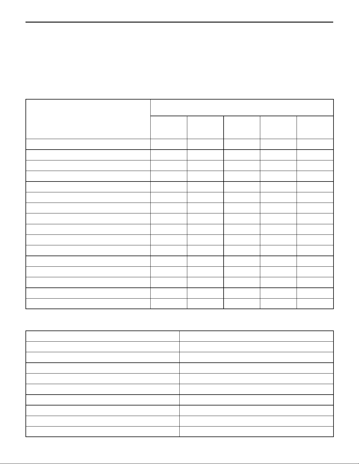
Aim (f: Newly adopted item;
F: Item already adopted on other engines)
Revision
Revised engine mounting alignment F
Serpentine-belt-driven auxiliary devices F
Three-layer cylinder head metal gasket F F
High-strength forged pistons f
Higher
performance
Quieter
operation
Cleaner
exhaust
emissions
Higher
reliability
Lower
weight
High-strength connecting rods f
Steel flywheel f f
High-capacity water pump f
Straight-port intake manifold F
Twin-scroll turbocharger f
Throttle body with new type of ISC system F F F
New type of compact throttle position sensor F F
New type of air flow sensor f
Secondary air system f
Low-noise fan alternator F
Crankshaft mounted crank angle sensor F F F
Plug-top ignition coils F F
MAJOR SPECIFICATIONS <EVOLUTION-IV>
Items 4G63-DOHC-T/C
Displacement (cc) 1,997
Cylinder bore stroke (mm) 85.0 88.0
Compression ratio 8.8
Valve mechanism DOHC 16-valve
Fuel Unleaded premium gasoline
Max. output (PS/rpm) 280/6,500
Max. torque (kgf⋅m/rpm) 36.0/3,000
Fuel supply Electronically controlled MPI
Ignition timing Electronically controlled
Page 3

ENGINE – Overview
Revision
1-3
OVERVIEW
<EVOLUTION-V>
The engine of the EVOLUTION-V is based on the 4G63 DOHC turbocharged unit used in the EVOLUTION-IV .
It incorporates the revisions shown below for increased output and durability.
Aim (f: Newly adopted item;
F: Item already adopted on other engines)
Higher performance
Crankshaft pins induction hardened f
Three-piece crankshaft thrust bearings F
Lighter pistons f f
Increased turbocharger nozzle area f
Higher maximum injector flow rate (MDL510
→ MDL560)
Heater added to O2 sensor F
Divided connection of positive crankcase
ventilation (PCV) system to intake manifold
f
Reduced exhaust
emissions
Higher reliability
MAJOR SPECIFICATIONS <EVOLUTION-V>
Items 4G63-DOHC-T/C
Displacement (cc) 1,997
Cylinder bore stroke (mm) 85.0 88.0
Compression ratio 8.8
Valve mechanism DOHC 16-valve
F
Fuel Unleaded premium gasoline
Max. output (PS/rpm) 280/6,500
Max. torque (kgf⋅m/rpm) 38.0/3,000
Fuel supply Electronically controlled MPI
Ignition timing Electronically controlled
Page 4
1-4
ENGINE – Engine Performance Curves
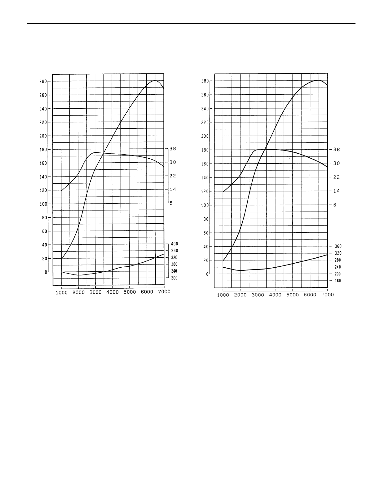
ENGINE PERFORMANCE CURVES
<EVOLUTION-IV>
4G63 DOHC with Turbocharger 4G63 DOHC with Turbocharger
Output (PS)
Output (PS)
Torque (kgf.m)
<EVOLUTION-V>
Torque (kgf.m)
Engine speed (rpm)
Fuel consumption rate (g/PS.h)
Engine speed (rpm)
Fuel consumption rate (g/PS.h)
Page 5
ENGINE – Main Unit
1-5
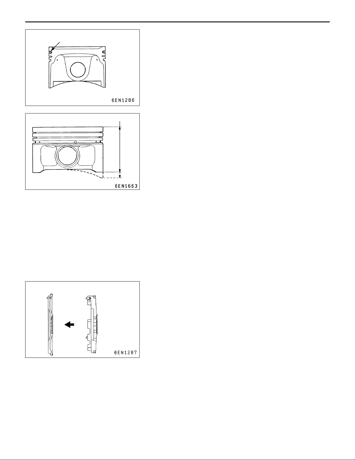
Alumite-treated
54.65 mm ← 61.65 mm
MAIN UNIT
PISTONS
(1) A revised production method enhances the pistons’ fatigue
strength.
(2) The No. 1 ring grooves are alumite-treated.
<EVOLUTION-V>
Reduced weight enhances engine responsiveness.
CONNECTING RODS
Shot blasting is performed again after coining, giving the connecting rods approximately 15% more fatigue strength than
the connecting rods used in the EVOLUTION-III.
Steel flywheel
Cast iron flywheel
FLYWHEEL
For lightness, the flywheel is made from steel instead of the
earlier cast iron.
Page 6
1-6
ENGINE – Lubrication System
LUBRICATION SYSTEM
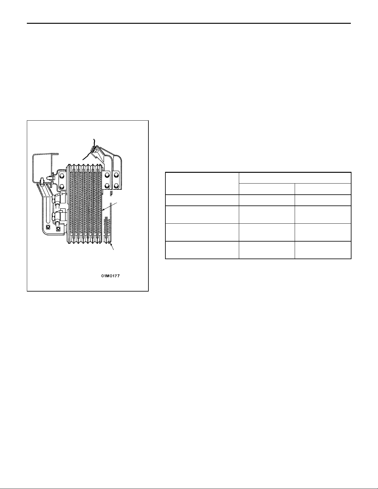
ENGINE OIL COOLER
<EVOLUTION-IV>
A corrugated-fin-type air-cooled engine oil cooler is utilized.
<EVOLUTION-V>
The oil cooler core has increased dimensions, and an air
duct has been added to the front bumper to improve the efficiency with which the engine oil is cooled.
Specifications
Item Specification
EVOLUTION-IV
Type Drawn-cup ←
EVOLUTION-IV EVOLUTION-V
EVOLUTION-V
Core dimensions (width
height depth) (mm)
Engine oil cooler oil
capacity (cc)
Heat release
(kW {kcal/h})
200 100 32 200 130 32
160 210
4.7 {4,080} 5.1 {4,380}
Page 7
ENGINE – Cooling System
{kgf⋅m})
1-7
COOLING SYSTEM
As compared with the EVOLUTION-IV’s cooling system, the EVOLUTION-V’ system incorporates the following
modifications for further enhancement of cooling performance:
2
D Revised radiator cap valve opening pressure (88 kPa {0.9 kgf/cm
D Modified radiator fan assembly
D Intercooler water spray system plus new radiator water spray system
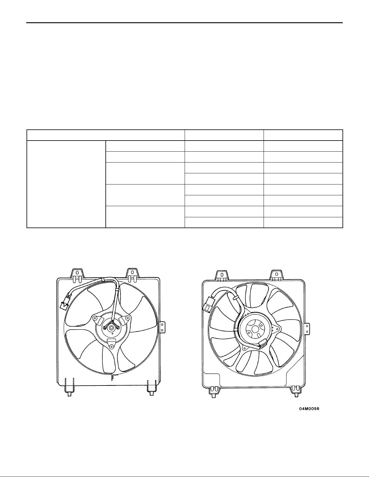
RADIATOR FAN ASSEMBLY
For improved cooling performance, the radiator fan’s shape has been modified and the motor specifications
have been revised.
Specifications
Item EVOLUTION-IV EVOLUTION-V
Radiator fan motor Manufacturer Calsonic ←
Type Direct-current ferrite ←
} → 108 kPa {1.1 kgf/cm2})
Rated load torque (Nm
Speed (r/min) LOW: 1,750 " 250 LOW: 1,900 " 250
Current (A) LOW: 12.0 (or lower) LOW: 13.3 (or lower)
LOW: 43.1 {4.4} LOW: 31.4 {3.2}
HI: 53.2 {5.4} HI: 53.9 {5.5}
HI: 2,100 " 250 HI: 2,200 " 250
HI: 15.5 (or lower) HI: 16.7 (or lower)
<EVOLUTION-V><EVOLUTION-IV>
Page 8

1-8
ENGINE – Cooling System
INTERCOOLER AND INTERCOOLER WATER SPRAY SYSTEM
A large intercooler is utilized to improve cooling performance. An intercooler water spray system sprays
water from the washer tank onto the intercooler’s front surface to lower the intercooler’s temperature.
The intercooler water spray system is basically the same as that used on the EVOLUTION-III.
Construction
Washer tank
Water spray nozzle
Intercooler
Bumper
Water
spray
Water
Intercooler
Floor console
Water spray
switch
Page 9

ENGINE – Cooling System
1-9
INTERCOOLER AND RADIATOR WATER SPRAY SYSTEM
<EVOLUTION-V>
The EVOLUTION-V is provided with a new radiator water spray system in addition to the intercooler water
spray system.
Radiator
Nozzle assembly
Nozzle assembly
(for radiator)
Air conditioner
condenser
Bumper face
for radiator
Nozzle assembly
(for intercooler)
WATER PUMP
The water pump’s inlet diameter and impeller diameter have
been increased to improve cooling performance.
Page 10

1-10
ENGINE – Intake and Exhaust Systems
INTAKE AND EXHAUST SYSTEMS
TURBOCHARGER
Low-speed performance and responsiveness are improved
by a twin-scroll turbocharger with a dual passage arrangement
from the exhaust manifold to the turbine.
Twin scroll
Dual exhaust
manifold
<EVOLUTION-V>
The nozzle cross-sectional area has been increased for improved performance at mid-range and high
speeds.
Section A-A
Nozzle cross-sectional area
Page 11

ENGINE – Intake and Exhaust Systems
1-11
EXHAUST PIPE
EVOLUTION-IV
The exhaust pipe is constructed in three parts. It has the following key features:
D Large, sound-absorbing pre-mufflers that reduce the high-frequency components of exhaust noise;
D A stainless steel main muffler that is highly resistant to corrosion;
D A heat-retaining cover on the front pipe that enhances the catalytic converter’s effectiveness.
Construction
Main muffler
Catalytic converter
Pre-muffler
EVOLUTION-V
D In accordance with revised safety regulations, the high temperature sensor and heat protectors have
been eliminated.
D In accordance with the addition of a front cross member bar (see “Suspension” in Group 3) the front
exhaust pipe has been provided with an indent to prevent interference <vehicles with 17-inch wheels>.
High temperature sensor (eliminated)
<Vehicles with 17-inch wheels>
Front exhaust pipe
Indent
Front cross
member bar
Heat protector (eliminated)
Page 12

1-12
ENGINE – Mounting
Rear roll
stopper
Insulator diameter reduced
from φ70 mm to φ60 mm
MOUNTING
REAR ROLL STOPPERS <EVOLUTION-V>
Front of
vehicle
Center member
The insulator diameter has been reduced from φ70 mm to
φ60 mm to reduce engine roll.
CENTER MEMBER <EVOLUTION-V>
D Rigid mounting of the center member (achieved using added spacers) decreases engine roll.
D In accordance with the addition of a front cross member bar (see “Suspension” in Group 3) a bracket
has been added to the lower reinforcement to protect the heads of the front cross member bar’s
mounting bolts and a front cross member bar mounting nut has been added <vehicles with 17-inch
wheels>.
Center Member Mounting
<EVOLUTION-V><EVOLUTION-IV>
Collar
Upper bushing
Lower bushing
Center member
Center member
NOTE:
This drawing shows the front mounting. The rear mounting is similar.
Rigid mounting spacer (added)
Front cross member bar
mounting nut (added)
Front of
vehicle
Bracket added to lower reinforcement to protect
heads of front cross member bar mounting bolts
<vehicles with 17-inch wheels>
Rigid mounting spacer (added)
Page 13

ENGINE – Fuel System / Control System
1-13
FUEL SYSTEM
The fuel system is basically the same as that of the 4G63 DOHC turbocharged engine used in the EVOLUTIONIII.
Fuel filter
Intake manifold
Delivery pipe
Injector
Injector
Engine
Injector
Injector
Fuel pressure control
solenoid valve
Fuel pressure
regulator
(regulated pressure:
294 kPa {3.00 kgf/cm
Fuel tank
2
})
Filter
Fuel pump
CONTROL SYSTEM
The control system is based on that of the 4G63 DOHC turbocharged engine used in the EVOLUTION-III.
For enhanced torque and output, it incorporates the following improvements:
(1) A new type of air flow sensor significantly reduces air intake resistance.
(2) A flow-limiter-type idle speed control system provides superior control over the engine’s idle speed
during warm-up.
(3) The crank angle sensor is attached directly to the crankshaft to enhance accuracy.
(4) A stick-type cam position sensor is used.
(5) The ignition system utilizes plug-top coils with built-in power transistors for enhanced ignition performance.
(6) An alternator control system enhances fuel efficiency while the engine is idling.
(7) A high/low two-speed fan control relay is utilized.
(8) The engine control relay and fuel pump control relay are located separately to enable simpler circuitry.
(9) A secondary air system has been added to enhance acceleration response.
(10)The ignition timing adjustment connector has been eliminated.
(11)The air conditioner refrigerant medium pressure switch has been eliminated.
Page 14

1-14
ENGINE – Control System
Air flow sensor (AFS)
Intake temperature sensor
Atmospheric pressure sensor
Coolant temperature sensor
Throttle position sensor (TPS)
Idle switch
Cam position sensor
Crank angle sensor
O2 sensor
Vehicle speed sensor
Air conditioner switch
Power steering fluid pressure switch
Engine ECU
[1] Fuel injection control
[2] Idle speed control (ISC)
[3] Ignition timing control
[4] Control relay control
(supply of power to sensors and actuators)
[5] Fuel pump control
[6] Air conditioner relay con-
trol
[7] Air flow sensor filter reset
control
[8] Alternator control
[9] Fan relay control (radiator; air
conditioner condenser)
[10] Fuel pressure control
[11] Boost pressure control
No. 1 injector
No. 2 injector
No. 3 injector
No. 4 injector
ISC servo (stepper motor)
Ignition coils (power transistors)
Control relay
Fuel pump relay
Air conditioner relay
Air flow sensor (AFS)
Alternator G terminal
Fan motor relay (radiator; air conditioner condenser)
Fuel pressure control valve
Wastegate solenoid valve
Alternator FR terminal
Ignition switch IG terminal
Ignition switch ST terminal
Knock sensor
Power supply
High temperature sensor
Diagnosis control terminal
[12] Secondary air control
[13] Fuel pump delivery rate
control
[14] Exhaust temperature warning
lamp control
[15] Engine warning lamp control
[16] Diagnosis output
[17] Engine speed output
[18] RAM data transmission
Secondary air control solenoid
valve
Fuel pump relay No. 2
Exhaust temperature warning
lamp
Engine warning lamp
Diagnosis output terminal
Tachometer
Diagnosis output terminal (MUT -II)
Page 15

<4G63 DOHC with Turbocharger>
Vehicle speed sensor
Air conditioner switch
Power steering fluid pressure switch
Alternator FR terminal
Ignition switch IG terminal
Ignition switch ST terminal
Power supply
Cam position sensor
Crank angle sensor
High temperature sensor
Coolant temperature sensor
Knock sensor
O
Atmospheric pressure sensor
Air flow sensor
Intake temperature sensor
Idle switch
Throttle position sensor
ENGINE – Control System
Engine ECU
Injectors
sensor
2
Fuel pressure control valve
ISC servo
Wastegate solenoid valve
Secondary air control solenoid valve
1-15
Ignition coils (power transistors)
Control relays
Fuel pump relay
Air conditioner relay
Alternator G terminal
Fan motor relay
Exhaust temperature warning lamp
Engine warning lamp
Diagnosis output terminal
Tachometer
Secondary
air valve
Page 16

1-16
ENGINE – Control System
Air flow sensing
element
Air
Air deflector
Bypass
passage
Air
Vortex-inducing
pillar
Air flow sensing circuitry
Vortex-inducing pillar
Bypass passage
Shape of
conventional
sensor
Air from
bypass
passage
Kármán
vortex
SENSORS
Air Flow Sensor (Incorporating Atmospheric Pressure
Sensor)
To reduce pressure losses and thus improve performance,
Mitsubishi Motors developed a new air flow sensor known
as MUKAS. In contrast with a conventional sensor, which
senses Kármán vortices downstream of a vortex-inducing pillar
using a pressure-sensitive element, the MUKAS sensor counts
Kármán vortices in a bypass passage using a hot-wire arrangement.
Pressure losses
reduced by 50%
Size and weight
reduced by 20%
Improved resistance
to contamination and
noise
Increased sensitivity at low air flow
rates enables the use of a larger air
inlet. Thus, pressure losses are reduced.
A more condensed circuit layout
and a new, compact connector enable a significant reduction in overall length.
Only a small amount of air flows
through the bypass passage, so
contamination is greatly reduced.
Also, Kármán vortices are mea-
sured digitally in accordance with
the difference in signals received
from left and right hot-wire arrangements, so the sensor is resistant to
noise and to changes in the components that occur over time.
From air
intake hose
ACTUATORS
Secondary Air Control Solenoid Valve
The secondary air control valve is an ON/OFF solenoid valve.
It switches the pressure applied to the secondary air valve
between the intake manifold vacuum pressure and the atmospheric pressure.
When the coil is not energized, continuity exists between the
X-nipple and ambient air. When the coil is energized, continuity
exists between the X-nipple and Y-nipple.
Secondary Air Valve
The secondary air valve turns ON and OFF the secondary
air supply by opening and closing in accordance with the vacuum pressure applied to the diaphragm chamber.
To exhaust
manifold
Page 17

FUEL INJECTION CONTROL
Fuel pressure
regulator
To fuel tank
To cam
rear side
From fuel
pump
ENGINE – Control System
Fuel pressure
control valve
Engine ECU
Injectors
Air flow sensor
Intake temperature sensor
Atmospheric pressure sensor
Throttle position sensor
Idle switch
Ignition switch ST terminal
sensor
O
2
Vehicle speed sensor
Crank angle sensor
Knock sensor
Coolant temperature sensor
Cam position sensor
1-17
IDLE SPEED CONTROL
Bimetallic limiter
To intake manifold
ISC servo
(stepper motor)
Speed adjusting
screw (SAS)
From air cleaner
Engine ECU
Ignition switch IG terminal
Ignition switch ST terminal
Power steering fluid pressure switch
Air conditioner switch
Vehicle speed sensor
Crank angle sensor
Coolant temperature sensor
Atmospheric pressure sensor
Air flow sensor
Intake temperature sensor
Throttle position sensor
Idle switch
Alternator FR terminal
Page 18

1-18
ENGINE – Control System
IGNITION TIMING AND ENERGIZATION TIME CONTROL
Air flow sensor
Intake temperature sensor
Atmospheric pressure sensor
Coolant temperature sensor
Idle switch
Cam position sensor
Crank angle sensor
Vehicle speed sensor
Ignition switch ST terminal
Knock sensor
Engine ECU
Tachometer
Ignition coil B
Cylinders
Ignition
switch
Ignition coil A
Battery
Page 19

ENGINE – Control System
POWER SUPPLY AND FUEL PUMP CONTROL
Battery
1-19
Ignition
switch
Fuel
pump
relay
Fuel pump control
Engine ECU
To fuel
pump
Ignition switch
IG signal
To injectors, ISC
servo, etc.
Control
relay
Power
supply
Backup
power
Power
control
AIR CONDITIONER RELAY CONTROL; AIR FLOW SENSOR FILTER RESET CONTROL;
FUEL PRESSURE CONTROL; BOOST PRESSURE CONTROL; EXHAUST TEMPERATURE WARNING LAMP CONTROL
The control arrangement is the same as that used with the 4G63 DOHC turbocharged engine of the EVOLUTION-III.
Page 20

1-20
ALTERNATOR CONTROL
ENGINE – Control System
Coolant temperature sensor
Crank angle sensor
Air conditioner switch
Power steering fluid pressure
switch
Ignition switch ST terminal
Engine ECU
Alternator G terminal
Alternator FR terminal
Alternator
ENGINE SPEED OUTPUT
Engine speed signals are issued in synchronization with crank angle sensor signals.
Engine ECU
Crank angle
sensor signals
To tachometer
Engine speed
signals
Page 21

ENGINE – Control System
1-21
F AN MOTOR RELA Y (RADIA TOR FAN; AIR CONDITIONER CONDENSER FAN) CONTROL
Battery
Ignition switch
Radiator fan
motor relay
(HI)
Radiator
fan motor
Radiator fan
motor relay (LO)
Condenser
fan motor
relay (HI)
Condenser
fan motor
Engine ECU
High-speed side
Condenser fan
motor relay (LO)
Coolant temperature
sensor
Throttle position sensor
Idle switch
Crank angle sensor
Air conditioner switch
Condenser fan
operation
Air conditioner
switch
Engine coolant
temperature (°C)
Power transistor
(low-speed side)
Low-speed side
Power transistor
(high-speed side)
Radiator fan
operation
OFF Below approx. 95 OFF OFF Stationary Stationary
Approx. 95 to 105 ON OFF Low speed Low speed
Above approx. 105 ON ON High speed Low speed
ON Below approx. 105 ON OFF Low speed Low speed
Above approx. 105 ON ON High speed High speed
Page 22

1-22
ENGINE – Control System
SECONDARY AIR CONTROL
During deceleration from a high speed, secondary air is introduced upstream of the turbocharger. This
operation prevents the turbine’s speed from dropping and thus enhances responsiveness when the driver
next wishes to accelerate. For maximum effectiveness, secondary air is introduced into the exhaust manifold
immediately downstream of each cylinder.
Engine ECU
Secondary air
control solenoid
valve
Secondary air
valve
Control relay
Battery
Vacuum
tank
Secondary air is introduced for approximately three minutes when both of the following conditions are
satisfied:
D The engine speed is 4,000 rpm or higher.
D The engine speed drops sharply after at least three seconds of full-throttle acceleration.
Page 23

Control
relay
Ignition
switch
Fuel pump
relay No. 2
Engine ECU
Battery
ENGINE – Control System
FUEL PUMP DELIVERY RATE CONTROL
1-23
Fuel
pump
Resistor
Page 24

1-24
ENGINE – Control System
SELF-DIAGNOSIS SYSTEM
Engine Warning Lamp (Check Engine Lamp) Control
The engine warning lamp illuminates in the event of an abnormality in any of the items shown in the
following table.
Air flow sensor Atmospheric pressure sensor
Intake temperature sensor Knock sensor
Throttle position sensor Injectors
Coolant temperature sensor Ignition coils; power transistor units
Crank angle sensor Engine ECU
Cam position sensor
Diagnosis Function
Diagnosis items are shown in the following table.
Code No. Diagnosis item Main fault(s) diagnosed
12 Air flow sensor Open/short circuit in sensor-related circuitry No
13 Intake temperature sensor Open/short circuit in sensor-related circuitry No
14 Throttle position sensor Abnormal sensor output No
21 Coolant temperature sensor D Open/short circuit in sensor-related circuitry
D Increased contact resistance in connector
22 Crank angle sensor Abnormal sensor output No
23 Cam position sensor Abnormal sensor output No
24 Vehicle speed sensor Open/short circuit in sensor circuitry No
25 Atmospheric pressure sensor Open/short circuit in sensor-related circuitry No
31 Knock sensor Abnormal sensor output No
41 Injectors Open/short circuit in injector-related circuitry No
44 Ignition coils; power transistor units Abnormality in ignition system (failure in one out
of two coils)
64 Alternator FR terminal Open circuit in sensor circuitry No
— Normal state — —
Dealer mode
diagnosis
No
No
Page 25

ENGINE – Control System
Service Data Output
Service data output items are shown in the following table.
Item No. Service data item Unit
11 O2 sensor mV
12 Air flow sensor output Hz
13 Intake temperature sensor output °C
14 Throttle position sensor output mV
16 Battery voltage V
18 Cranking signal (ignition switch ST terminal) ON-OFF
21 Coolant temperature sensor output °C
22 Crank angle sensor output RPM
25 Atmospheric pressure sensor output kPa
26 Idle switch ON-OFF
27 Power steering fluid pressure switch ON-OFF
28 Air conditioner switch ON-OFF
1-25
41 Injector energization time ms
44 Ignition advance angle °BTDC, °ATDC
45 ISC stepper motor position STEP
49 Air conditioner relay ON-OFF
Actuator Tests
Actuator test items are shown in the following table.
Item No. Actuator test item
01 No. 1 injector: OFF
02 No. 2 injector: OFF
03 No. 3 injector: OFF
04 No. 4 injector: OFF
07 Fuel pump: ON
09 Fuel pressure control valve: ON
12 Wastegate solenoid valve: ON
13 Fuel pump relay No. 2: ON (current supplied via resistor)
17* Ignition timing: 5°BTDC
20 Radiator fan (high), air conditioner condenser fan (high): high-speed operation
21 Radiator fan (low), air conditioner condenser fan (low): low-speed operation
30* ISC servo: locked in reference step during SAS adjustment
*: Continues for 27 minutes unless cancelled by depression of clear key.
Page 26

1-26
ENGINE – Exhaust Emission Control System
EXHAUST EMISSION CONTROL SYSTEM
System Diagram
Canister
Check valve
O
sensor
2
PCV valve
Fuel pressure
regulator
Injector
Intake air
High temperature sensor
Three-way catalytic converter
 Loading...