

Page 1

BASIC BRAKE
SYSTEM
CONTENTS
35A-1
SERVICE SPECIFICATIONS 2. . . . . . . . . . . . . .
LUBRICANTS 2. . . . . . . . . . . . . . . . . . . . . . . . . . .
SEALANT 3. . . . . . . . . . . . . . . . . . . . . . . . . . . . . . .
SPECIAL TOOLS 3. . . . . . . . . . . . . . . . . . . . . . . .
ON-VEHICLE SERVICE 3. . . . . . . . . . . . . . . . . .
1. Brake Booster Operation Check 3. . . . . . . .
2. Proportioning Valve Function Test 3. . . . . . .
3. Bleeding <EVOLUTION-V> 4. . . . . . . . . . . . .
4. Disc Brake Pad Check and Replacement
<EVOLUTION-IV> 4. . . . . . . . . . . . . . . . . . . . .
5. Disc Brake Pad Check and Replacement
<EVOLUTION-V> 4. . . . . . . . . . . . . . . . . . . . .
6. Brake Disc Thickness Check 6. . . . . . . . . . .
7. Brake Drum I.D. Check 6. . . . . . . . . . . . . . . .
8. Lining to Brake Drum Contact Check 6. . .
FRONT BRAKE 7. . . . . . . . . . . . . . . . . . . . . . . . . .
REAR BRAKE 8. . . . . . . . . . . . . . . . . . . . . . . . . . .
Page 2
35A-2
action test generated fluid pres
test generated fluid pressure kPa
BASIC BRAKE SYSTEM – Service Specifications / Lubricants
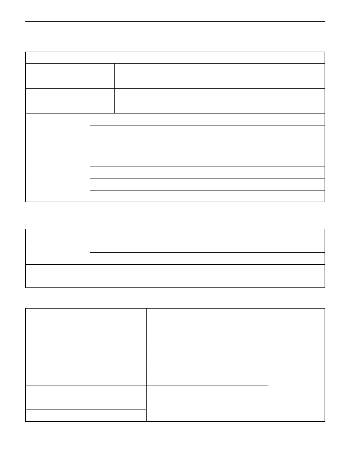
SERVICE SPECIFICATIONS
<EVOLUTION-IV>
Items
Brake booster nonboosting
f
sure kPa {kgf/cm2}
Brake booster boosting actionfPedal force 98 N {10 kgf} 2,354 – 3,334 {24 – 34} –
{kgf/cm2}
Proportioning valve Split point kPa {kgf/cm2} 2,697 – 3,187 {27.5 – 32.5} –
Output fluid pressure kPa {kgf/cm2}
(input fluid pressure kPa {kgf/cm2})
Front disc brake drag force N {kgf} 51 {5.2} –
Rear disc brake Brake pad thickness mm 10.0 2.0
Brake disc thickness mm 20.0 18.4
Brake drag force N {kgf} 69 {7.0} –
Brake drum I.D. mm 168.0 169.0
Pedal force 98 N {10 kgf} 49 {0.5} or more –
-
Pedal force 294 N {30 kgf} 1,177 {12} or more –
Pedal force 294 N {30 kgf} 6,963 – 9,414 {71 – 96} –
Standard value Limit
4,658 {47.5} (9,807 {100}) –
<EVOLUTION-V>
Same as EVOLUTION-IV except for followings.
Items
Front disc brake Brake pad thickness mm 10.0 2.0
Brake drag force N {kgf} 69 {7.0} –
Rear disc brake Brake pad thickness mm 10.0 2.0
Brake drag force N {kgf} 69 {7.0} –
Standard value Limit
LUBRICANTS
Items
Brake fluid MITSUBISHI GENUINE DIA QUEEN BRAKE
Piston boot, piston seal Repair kit grease
Guide pin, lock pin
Pin boot, guide pin sleeve
Piston, wheel cylinder body
Packing plate CHUO YUKA AKB100
Specified lubricant Quantity
FLUID SUPER
As required
Shoe & lining assembly
Auto adjuster assembly
Page 3
BASIC BRAKE SYSTEM – Sealant / Special Tools / On-vehicle Service
HELMESEAL 101Y [MZ100022 (containing 100 g)], [MZ100023 (containing 500 g)]
SEALANT
35A-3
Items
Fitting Semi-drying sealant: THREEBOND 1104 [0110207]
Vacuum switch
NOTE
Given in [ ] are the genuine part numbers.
Specified sealant
HELMESEAL 201-52B [0110511 (containing 100 g)], [0110512 (containing 500 g)]
SPECIAL TOOLS
Tool
1
Number Name Use
MB990964
1: MB991008
(F)
Brake tool set Installation of rear drum brake piston cup
ON-VEHICLE SERVICE
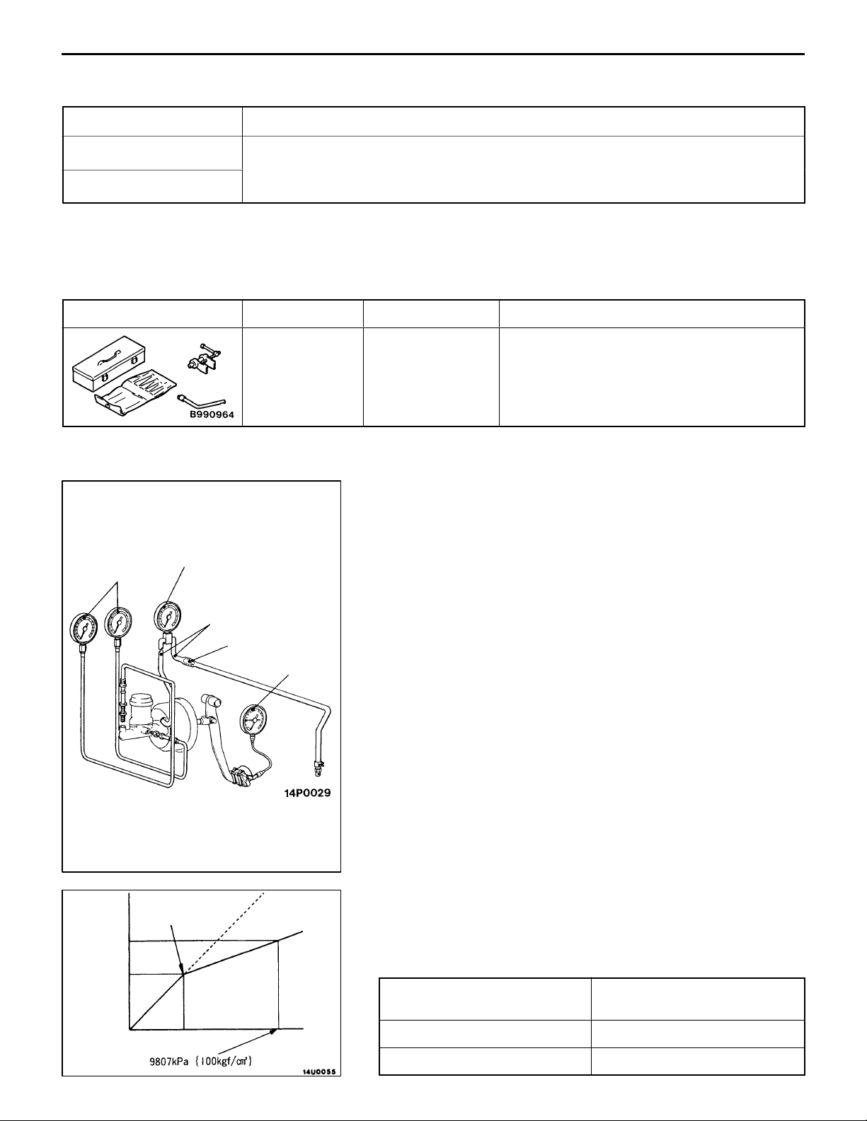
1. BRAKE BOOSTER OPERATION CHECK
Pressure
gauges
Vacuum gauge
The conventional procedures apply except for the following
standard value.
Nonboosting action test
Output
fluid
pressure
Split point
Vacuum hose
Check
valve
Pedal
pressure
gauge
Standard value:
2
Fluid pressure generated kPa {kgf/cm
}
Pedal force 98 N {10 kgf}: 49 {0.5} or more
Pedal force 294 N {30 kgf}: 1,177 {12} or more
Boosting action test
Standard value:
2
Fluid pressure generated kPa {kgf/cm
}
Pedal force 98 N {10 kgf}: 2,354 – 3,334 {24 – 34}
Pedal force 294 N {30 kgf}: 6,963 – 9,414 {71 – 96}
2. PROPORTIONING VALVE FUNCTION TEST
The conventional procedures apply except for the following
standard value.
Standard value:
Input fluid pressure
kPa {kgf/cm2}
Output fluid pressure
kPa {kgf/cm2}
Input fluid pressure
Split point 2,697 – 3,187 {27.5 – 32.5}
9,807 {100} 4,658 {47.5}
Page 4
35A-4
BASIC BRAKE SYSTEM – On-vehicle Service
Air bleeder screws
<Front> <Rear>
3. BLEEDING <EVOLUTION-V>
Connect a vinyl tube to the outer end of the air bleeder screw
to bleed the circuit of air. Then, connect the vinyl tube to
the inner end and bleed the circuit of air. Except for these,
the conventional procedures shall be followed. After the circuit
has been bled of air, tighten both air bleeder screws to the
specified torque.
4. DISC BRAKE PAD CHECK AND
REPLACEMENT <EVOLUTION-IV>
4-1 FRONT BRAKE
Use the same procedure as that for the 2-pot type disc brake.
4-2 REAR BRAKE
The conventional procedures apply except for the following
standard value for the brake pad thickness.
Standard value (brake pad thickness): 10.0 mm
Limit: 2.0 mm
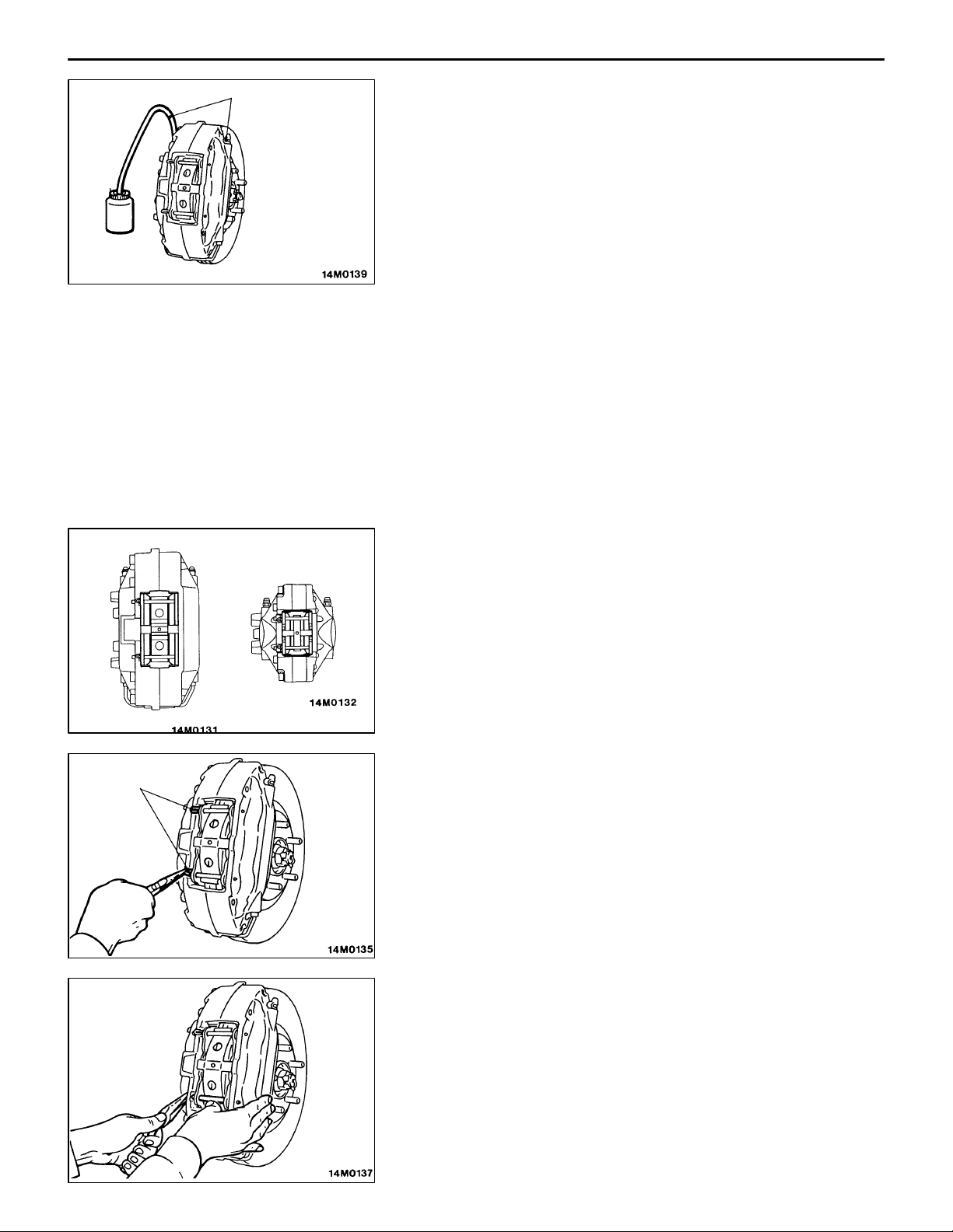
5. DISC BRAKE PAD CHECK AND
REPLACEMENT <EVOLUTION-V>
NOTE
The wear indicator contacts the brake disc to squeak when
the pad thickness becomes about 2 mm, warning the driver
that the pad needs replacement.
(1) Visually check for the brake pad thickness through the
inspection hole in the caliper body.
Clips
Standard value: 10.0 mm
Limit: 2.0 mm
(2) If the brake pad thickness is less than the limit, follow
steps (3) and onward to replace the brake pads on both
sides with new ones as a set.
(3) Remove clips from the pins.
(4) Holding the cross spring with one hand, pull the pin out
of the caliper.
Page 5

BASIC BRAKE SYSTEM – On-vehicle Service
(5) Remove the pad from the caliper.
(6) To measure brake drag force after new pads have been
installed, use a spring balance to measure the turning
sliding resistance of the hub with the pads removed.
(7) Clean the piston and, using the special tool, push the
piston into the cylinder.
35A-5
<Front> <Rear>
Pins
Cross
spring
(8) Apply repair kit grease to the portions of the pads indicated
on the left. At this time, make sure that the grease will
not be applied to any other surfaces.
(9) Mount the pad to the caliper so that its side with the
wear indicator is on the outside of the vehicle. With the
rear pad, ensure that the arrow on the pad faces in the
same direction as the brake disc turns when the vehicle
moves forward.
(10)Holding the cross spring with one hand, fit pins in the
caliper.
(11)Mount clips to the pins.
(12)Using a spring balance, measure the turning sliding
resistance of the hub in the forward direction.
(13)Find the brake disc drag force [the difference in
measurements taken in step (6) and in step (12)].
Standard value: 69 N {7.0 kgf}
Page 6

35A-6
BASIC BRAKE SYSTEM – On-vehicle Service
6. BRAKE DISC THICKNESS CHECK
(1) Remove dirt and rust from the surface of the brake disc.
(2) Measure the thickness of the disc, over which the pad
slides, at 4 places or more.
Standard value: <Front> 24.0 mm
<Rear> 20.0 mm
Limit: <Front> 22.4 mm
<Rear> 18.4 mm
(3) If any of the brake disc thickness measurements exceeds
the limit, replace the brake discs and brake pads on both
sides as a set.
7. BRAKE DRUM I.D. CHECK
(1) Remove the rear brake assembly and support it with a
wire.
(2) Remove the brake disc.
(3) Measure the I.D. of the brake drum at 2 places or more.
Standard value: 168.0 mm
Limit: 169.0 mm
(4) If the brake drum I.D. has worn to exceed the limit, or
if an excessive eccentric wear is evident, replace the
brake disc with a new one.
8. LINING TO BRAKE DRUM CONTACT
CHECK
(1) Remove the rear brake assembly and support it with a
wire.
(2) Remove the brake disc.
(3) Remove the shoe & lining assembly. (Refer to GROUP
36.)
(4) Apply chalk to the brake disc inner surface (brake drum)
and rub the shoe & lining assembly against it.
(5) If any irregular contact is evident, replace the shoe &
lining assembly or brake disc.
NOTE
Wipe the surfaces clean of chalk after the check has
been completed.
Page 7

BASIC BRAKE SYSTEM – Front Brake
FRONT BRAKE
REMOVAL AND INSTALLATION
Except for the followings, use the same procedure as that
for conventional disc brake.
INSTALLATION SERVICE POINT
"AA DISC BRAKE ASSEMBLY INSTALLATION
Follow the conventional procedures except the standard value
for the disc brake drag force.
Standard value (disc brake drag force):
51 N {5.2 kgf} <EVOLUTION-IV>
69 N {7.0 kgf} <EVOLUTION-V>
DISASSEMBLY AND REASSEMBLY
NOTE
On EVOLUTION-IV, follow the same procedure as conventional.
On EVOLUTION-V, disassemble in the order shown.
35A-7
7
6
7
2
1
5
3
1
8
6
5
4
Grease: Repair kit grease
4
Disassembly steps
1. Clip
2. Pin
3. Cross spring
4. Pad & wear indicator assembly
5. Pad assembly
6. Air bleeder screw
7. Cap
8. Disc brake caliper assembly
Page 8

35A-8
BASIC BRAKE SYSTEM – Rear Brake
REAR BRAKE
REMOVAL AND INSTALLATION
Pre-removal Operation
D Brake Fluid Draining
49 – 59 {5.0 – 6.0}
Removal steps
1. Brake hose connection
2. Gasket
"AA 3. Rear brake assembly
4. Brake disc
Post-installation Operation
D Brake Fluid Refilling and Bleeding
29 {3.0}
1
2
3
4
Unit: Nm {kgf@m}
NOTE
Shown here is the illustration of rear brake for
EVOLUTION-IV.
INSTALLATION SERVICE POINT
"AA DISC BRAKE ASSEMBLY INSTALLATION
Follow the conventional procedures except the standard value
for the disc brake drag force.
Standard value (disc brake drag force): 69 N {7.0 kgf}
Page 9

BASIC BRAKE SYSTEM – Rear Brake
DISASSEMBLY AND REASSEMBLY
<EVOLUTION-IV>
35A-9
13
43 {4.4}
14 14
11
11
2
14
7.8 {0.8}
12
5
11
13
9
8
1
3
10
7
6
4
14
5
12
13
3
9
5
7
12
14
14
Pad kit
2
1
3
5
Brake caliper kit
Disassembly steps
"AA 1. Lock pin
"AA 2. Guide pin
3. Bushing
4. Caliper support (pad, clip, shim)
5. Pin boot
6. Boot ring
AA" 7. Piston boot
Unit: Nm {kgf@m}
6
Grease
Seal & boot kit
5
5
9
4
8
7
6
AA" 8. Piston
AB" 9. Piston seal
10. Caliper body
11. Pad & wear indicator assembly
12. Pad assembly
13. Outer shim
14. Clip
Page 10

35A-10
BASIC BRAKE SYSTEM – Rear Brake
LUBRICANT APPLICATION POINTS
Caution
Do not wipe the piston seal in the
seal & boot kit clean of the special
grease applied to it.
Brake fluid:
MITSUBISHI GENUINE
DIA QUEEN BRAKE
FLUID SUPER 4
Grease: Repair kit grease
Grease: Repair kit grease
Grease: Repair kit grease
Page 11

BASIC BRAKE SYSTEM – Rear Brake
DISASSEMBLY SERVICE POINTS
AA" PISTON BOOT / PISTON REMOVAL
Cover the outer end of the caliper body with a cloth. Blow
compressed air through the brake hose connection to remove
the piston and piston boot.
Caution
Do not send a sudden blast of air, as it causes the piston
to rush out. Send a gentle, gradual blow of compressed
air.
AB" PISTON SEAL REMOVAL
(1) Remove the piston seal with a finger tip.
Caution
Do not use a flat-blade screwdriver or similar tool
to prevent the cylinder inner surface from being
damaged.
(2) Clean the piston surface and cylinder inner surface with
trichloroethylene, alcohol, or the specified brake fluid.
Brake fluid:
MITSUBISHI GENUINE DIA QUEEN BRAKE FLUID
SUPER 4
35A-11
ID mark “L”
ID mark “G”
Front
INSTALLATION SERVICE POINT
"AA LOCK PIN / GUIDE PIN INSTALLATION
Install the guide pin and lock pin so that each head mark
matches the ID mark indicated on the caliper body as illustrated
on the left.
INSPECTION
PAD WEAR CHECK
Measure the thickness at a location that wears most of the
pad. If the thickness is less than the limit, replace the pad
assembly.
Standard value: 10.0 mm
Limit: 2.0 mm
Caution
(1) Whenever a pad is to be replaced with a new one,
be sure to replace both right and left sides as a set.
(2) If there is an excessive difference in pad thickness
noted between the right and left ones, check the
sliding mechanism.
Page 12

35A-12
BASIC BRAKE SYSTEM – Rear Brake
DISASSEMBLY AND REASSEMBLY
<EVOLUTION-V>
5
7
6
8
Disassembly steps
1. Clip
2. Pin
3. Cross spring
4. Pad & wear indicator assembly
3
5
4
1
Grease: Repair kit grease
2
5. Pad assembly
6. Air bleeder screw
7. Cap
8. Disc brake caliper assembly
4
 Loading...