

Page 1

GROUP INDEX
LANCER
WORKSHOP MANUAL
SUPPLEMENT
FOREWORD
This Workshop manual contains procedures for
service mechanics, including removal, disassembly,
inspection, adjustment, reassembly and installation.
Use the following manuals in combination with this
manual as required.
General . . . . . . . . . . . . . . . . . . . . . . . .
Fuel . . . . . . . . . . . . . . . . . . . . . . . . . . .
00
13
TECHNICAL INFORMATION MANUAL
PYME0302
PYME0302-A
PYME0302-B
WORKSHOP MANUAL
CHASSIS GROUP PWME0302
PWME0302-A
PWME0302-B
BODY REPAIR MANUAL
PBME0302
PBME0302-A
PBME0302-B
PARTS CATALOGUE
B606K006A_
All information, illustrations and product descriptions
contained in this manual are current as at the time of
publication. We, however, reserve the right to make
changes at any time without prior notice or obligation.
©Mitsubishi Motors Corporation Oct. 2005
Page 2

GROUP 00
GENERAL
CONTENTS
VEHICLE IDENTIFICATION . . . . . . . 00-2 GENERAL DATA AND
SPECIFICATIONS . . . . . . . . . . . . . . . 00-3
00-1
Page 3
00-2
VEHICLE IDENTIFICATION
GENERAL
VEHICLE IDENTIFICATION
M1001000401448
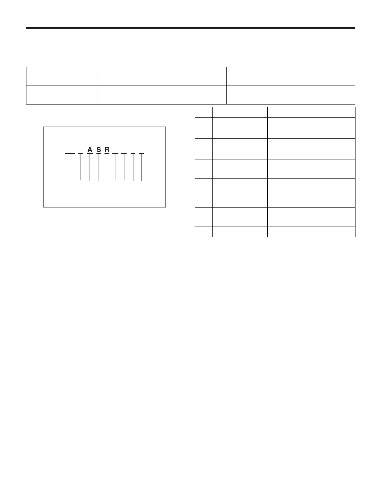
MODELS
Model code Engine model Price class Transmission model Fuel supply
system
CS9A SRHML6 4G63-DOHC (1,997 mL) Intense F4A4B
<2WD, 4A/T>
No. Item Content
MODEL CODE
CS 9 W L
123
LNHM 6
456789
AC303950
AC
1 Development CS: MITSUBISHI LANCER
2 Engine type 9: 1,997mL
3 Sort A: Passenger car
4 Body style S: 4-door sedan
5 Transmission
type
6 Trim level H: Intense
7 Specification
engine feature
8 Steering wheel
location
R: 4-speed automatic
transmission
M: MPI-DOHC
L: Left hand
MPI
9 Destination 6: For Europe
Page 4
GENERAL
GENERAL DATA AND SPECIFICATIONS
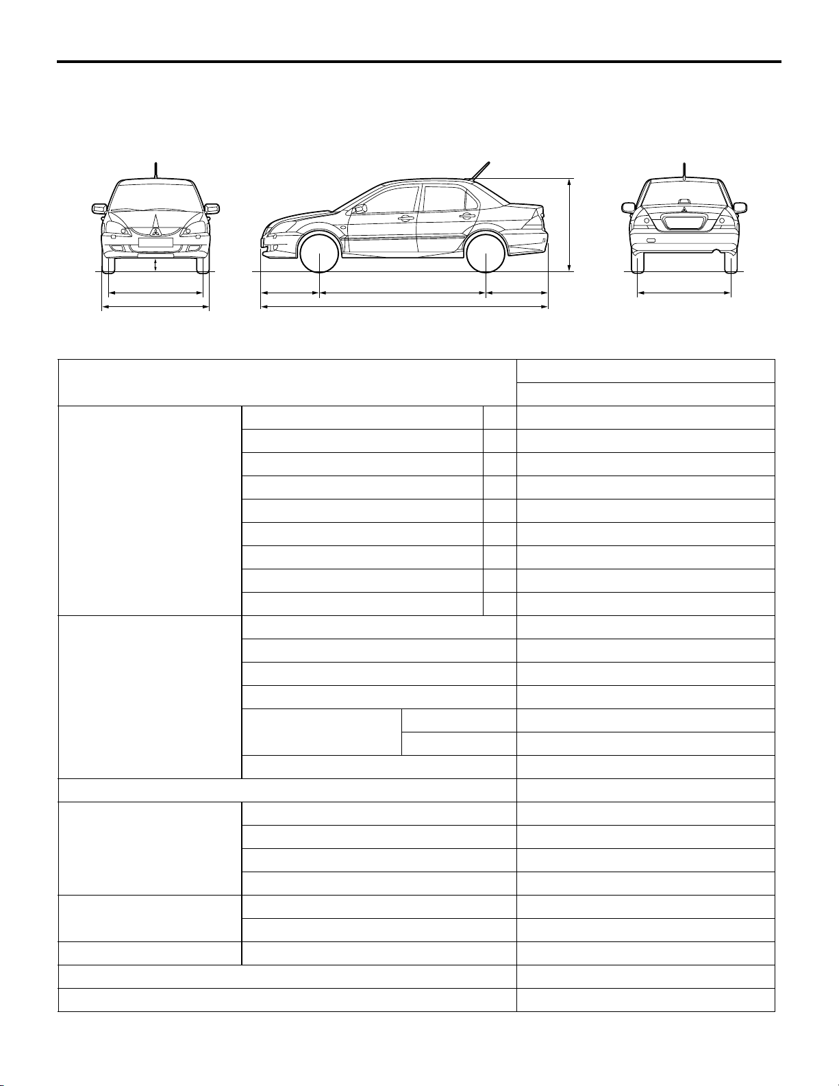
GENERAL DATA AND SPECIFICATIONS
8
7
1
2
3465
00-3
M1001000901197
9
Items CS9A
SRHML6
Vehicle dimensions mm Front track 1 1,470
Overall width 2 1,715
Front overhang 3 965
Wheel base 4 2,600
Rear overhang 5 970
Overall length 6 4,535
Ground clearance (unladen) 7 135
Overall height (unladen) 8 1,415
Rear track 9 1,470
Vehicle weight kg Kerb weight 1,295
Max. gross vehicle weight 1,770
Max. axle weight rating-front 930
Max. axle weight rating-rear 840
Max. trailer weight With brake 1,000
Without brake 400
Max. trailer-nose weight 60
AC303990
AB
Seating capacity 5
Engine Model code 4G63
To ta l d i spl ac em en t mL 1,997
Maximum output kW/r/min 99/5,750
Maximum torque N⋅m/r/min 176/4,500
Transmission Model code F4A4B
Type 4-speed automatic
Fuel system Fuel supply system MPI
Maximum speed km/h 187
Minimum turning radius m 5.7
Page 5

NOTES
Page 6

13D-1
MULTIPOINT FUEL
INJECTION (MPI)
<4G63>
CONTENTS
GENERAL 2.................................
Outline of Change 2............................
GENERAL INFORMATION 3...................
SERVICE SPECIFICATIONS 6.................
SEALANT 6..................................
SPECIAL TOOLS 7...........................
TROUBLESHOOTING 10......................
ON-VEHICLE SERVICE 90....................
Throttle Body (Throttle Valve Area)
Cleaning 90...................................
Throttle Position Sensor Adjustment 90............
Basic Idle Speed Adjustment 91..................
Fuel Pressure Test 92...........................
Component Location 95.........................
Engine Control Relay Continuity Check 96.........
Fuel Pump Relay Continuity Check 96.............
Intake Air Temperature Sensor Check 97..........
Engine Coolant Temperature Sensor Check 98.....
Throttle Position Sensor Check 98................
Oxygen Sensor Check 99.......................
Injector Check 101..............................
Idle Speed Control (ISC) Servo (Stepper Motor)
Check 102.....................................
Purge Control Solenoid Valve Check 104..........
EGR Control Solenoid Valve Check 104...........
Page 7

13D-2
MPI <4G63> ï General
GENERAL
OUTLINE OF CHANGE
Following service procedures have been established due to the addition of vehicles with 4G63-MPI engine
for Russia.
Page 8

MPI <4G63> ï General Information
GENERAL INFORMATION
13D-3
The Multipoint Fuel Injection System consists
of sensors which detect the engine conditions,
the engine-A/T-ECU which controls the system
based on signals from these sensors, and
actuators which operate under the control of
the engine-A/T-ECU. The engine-A/T-ECU
FUEL INJECTION CONTROL
The injector drive times and injection timing
are controlled so that the optimum air/fuel
mixture is supplied to the engine to correspond
to the continually-changing engine operation
conditions.
A single injector is mounted at the intake port
of each cylinder. Fuel is sent under pressure
from the fuel tank by the fuel pump, with the
pressure being regulated by the fuel pressure
regulator. The fuel thus regulated is distributed
to each of the injectors.
Fuel injection is normally carried out once for
each cylinder for every two rotations of the
crankshaft. The firing order is 1ï3ï4ï2. This
is called sequential fuel injection. The
carries out activities such as fuel injection
control, idle speed control and ignition timing
control. In addition, the engine-A/T-ECU is
equipped with several diagnosis modes which
simplify troubleshooting when a problem
develops.
engine-A/T-ECU provides a richer air/fuel
mixture by carrying out “open-loop” control
when the engine is cold or operating under
high load conditions in order to maintain engine
performance. In addition, when the engine is
warm or operating under normal conditions,
the engine-A/T-ECU controls the air/fuel mixture
by using the oxygen sensor signal to carry out
“closed-loop” control in order to obtain the
theoretical air/fuel mixture ratio that provides
the maximum cleaning performance from the
three way catalyst.
IDLE AIR CONTROL
The idle speed is kept at the optimum speed
by controlling the amount of air that bypasses
the throttle valve in accordance with changes
in idling conditions and engine load during
idling. The engine-A/T-ECU drives the idle
speed control motor to keep the engine running
at the pre-set idle target speed in accordance
with the engine coolant temperature and air
IGNITION TIMING CONTROL
The power transistor located in the ignition
primary circuit turns ON and OFF to control
the primary current flow to the ignition coil. This
controls the ignition timing in order to provide
the optimum ignition timing with respect to the
SELF-DIAGNOSIS FUNCTION
D When an abnormality is detected in one
of the sensors or actuators related to
emission control, the engine warning lamp
(check engine lamp) illuminates as a
warning to the driver.
D When an abnormality is detected in one
of the sensors or actuators, a diagnosis
conditioner load. In addition, when the air
conditioner switch is turned off and on while
the engine is idling, the idle speed control motor
operates to adjust the throttle valve bypass
air amount in accordance with the engine load
conditions in order to avoid fluctuations in the
engine speed.
engine operating conditions. The ignition timing
is determined by the engine-A/T-ECU from the
engine speed, intake air volume, engine coolant
temperature and atmospheric pressure.
code corresponding to the abnormality is
output.
D The RAM data inside the engine-A/T-ECU
that is related to the sensors and actuators
can be read by means of the M.U.T.-II/III.
In addition, the actuators can be
force-driven under certain circumstances.
Page 9
13D-4
Throttl
Throttl
60
Inject
tificati
k
HDA250E
MPI <4G63> ï General InformationMPI <4G63> ï General Information
OTHER CONTROL FUNCTIONS
1. Fuel Pump Control
3. Fan Motor Control
Turns the fuel pump relay ON so that current
is supplied to the fuel pump while the engine
is cranking or running.
2. A/C Relay Control
Turns the compressor clutch of the A/C
ON and OFF.
4. Purge Control Solenoid Valve Control
5. EGR Control Solenoid Valve Control
GENERAL SPECIFICATIONS
Item Specification
The revolutions of the radiator fan and
condenser fan are controlled in response to
the engine coolant temperature and vehicle
speed.
ebody
Engine-A/TECU
Sensors
ebore mm
Throttle position sensor Variable resistor type
Idle speed control servo Stepper motor type
Identification No. E6T37983
Air flow sensor Karman vortex type
Barometric pressure sensor Semiconductor type
Intake air temperature sensor Thermistor type
Engine coolant temperature sensor Thermistor type
Oxygen sensor Zirconia type
Inhibitor switch Contact switch type
Camshaft position sensor Hall element type
Crank angle sensor Hall element type
Detonation sensor Piezoelectric type
Power steering fluid pressure switch Contact switch type
Actuators
Fuel pressure
regulator
Engine control relay Contact switch type
Fuel pump relay Contact switch type
Injector type and number Electromagnetic type, 4
oriden
EGR control solenoid valve Duty cycle type solenoid valve
Purge control solenoid valve Duty cycle type solenoid valve
Regulator pressure kPa 328
on mar
Page 10
MPI <4G63> ï General Information
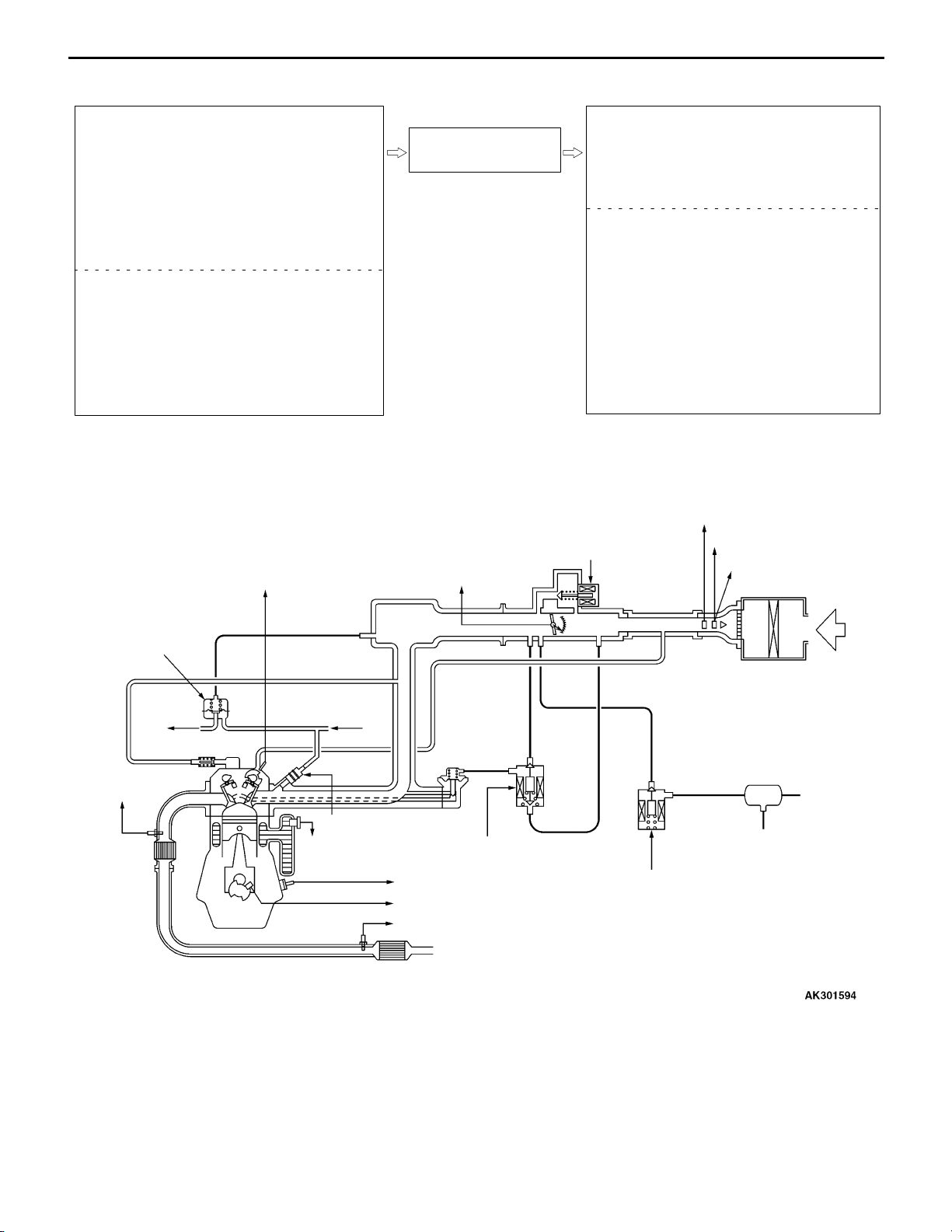
MULTI-POINT FUEL INJECTION SYSTEM DIAGRAM
13D-5
L1 Oxygen sensor (front)
L2 Oxygen sensor (rear)
L3 Air flow sensor
L4 Intake air temperature sensor
L5 Throttle position sensor
L6 Camshaft position sensor
L7 Crank angle sensor
L8 Barometric pressure sensor
L9 Engine coolant temperature sensor
L10 Detonation sensor
D Power supply
D Ignition switch-IG
D Ignition switch-ST
D A/C switch
D A/C load signal
D Power steering fluid pressure switch
D Alternator FR terminal
D Vehicle speed sensor
L6 Camshaft position sensor
Engine-A/T-ECU
L5 Throttle position
sensor
l1 Injector
l2 Idle speed control servo
(Stepper motor)
l3 EGR control solenoid valve
l4 Purge control solenoid valve
D Engine control relay
D Fuel pump relay
D A/C compressor relay
D Ignition coil
D Fan controller
D Air flow sensor filter reset signal
D Engine warning lamp
D Diagnosis output
D Alternator G terminal
D Oxygen sensor (front) heater
D Oxygen sensor (rear) heater
D Tachometer
L4 Intake air temperature sensor
l2 Idle speed control servo
(Stepper motor)
L3 Air flow sensor
L8 Barometric
pressure sensor
Fuel pressure
regulator
To
fuel tank
L1 Oxygen sensor
(front)
Catalytic
converter
From
fuel pump
l1 Injector
L9 Engine coolant
temperature sensor
L10 Detonation sensor
L7 Crank angle sensor
L2 Oxygen sensor (rear)
Catalytic converter
EGR valve
l3 EGR control
solenoid valve
Air
M
AM
Canister
l4 Purge control
solenoid valve
Page 11
13D-6
k
:
k
:
t
20_C)
:
MPI <4G63> ï Service Specifications/Sealant
SERVICE SPECIFICATIONS
Items Specifications
Basic idle speed r/min 750 r 50
Throttle position sensor adjusting voltage mV 535 ï 735
Throttle position sensor resistance k: 3.5 ï 6.5
Idle speed control servo coil resistance (at 20_C) : 28 ï 33
Intake air temperature sensor
resistance
Engine coolant temperature
sensor resistance
Oxygen sensor output voltage (at racing) V 0.6 ï 1.0
Oxygen sensor heater
resistance(a
_
ï20_C 13 ï 17
0_C 5.3 ï 6.7
20_C 2.3 ï 3.0
40_C 1.0 ï 1.5
60_C 0.56 ï0.76
80_C 0.30 ï 0.42
ï20_C 14 ï 17
0_C 5.1 ï 6.5
20_C 2.1 ï 2.7
40_C 0.9 ï 1.3
60_C 0.48 ï 0.68
80_C 0.26 ï 0.36
front 4.5 ï 8.0
rear 11 ï 18
Fuel pressure kPa Vacuum hose disconnection 324 ï 343 at kerb idle
Vacuum hose connection Approximately 265 at kerb idle
Injector coil resistance (at 20_C) : 10.5 ï 13.5
SEALANT
Item Specified sealant Remark
Engine coolant temperature sensor
threaded portion
3M Nut Locking Part No. 4171 or equivalent Drying sealant
Page 12
MPI <4G63> ï Special Tools
SPECIAL TOOLS
Too l Number Name Use
13D-7
MB991502 M.U.T.-II sub
assembly
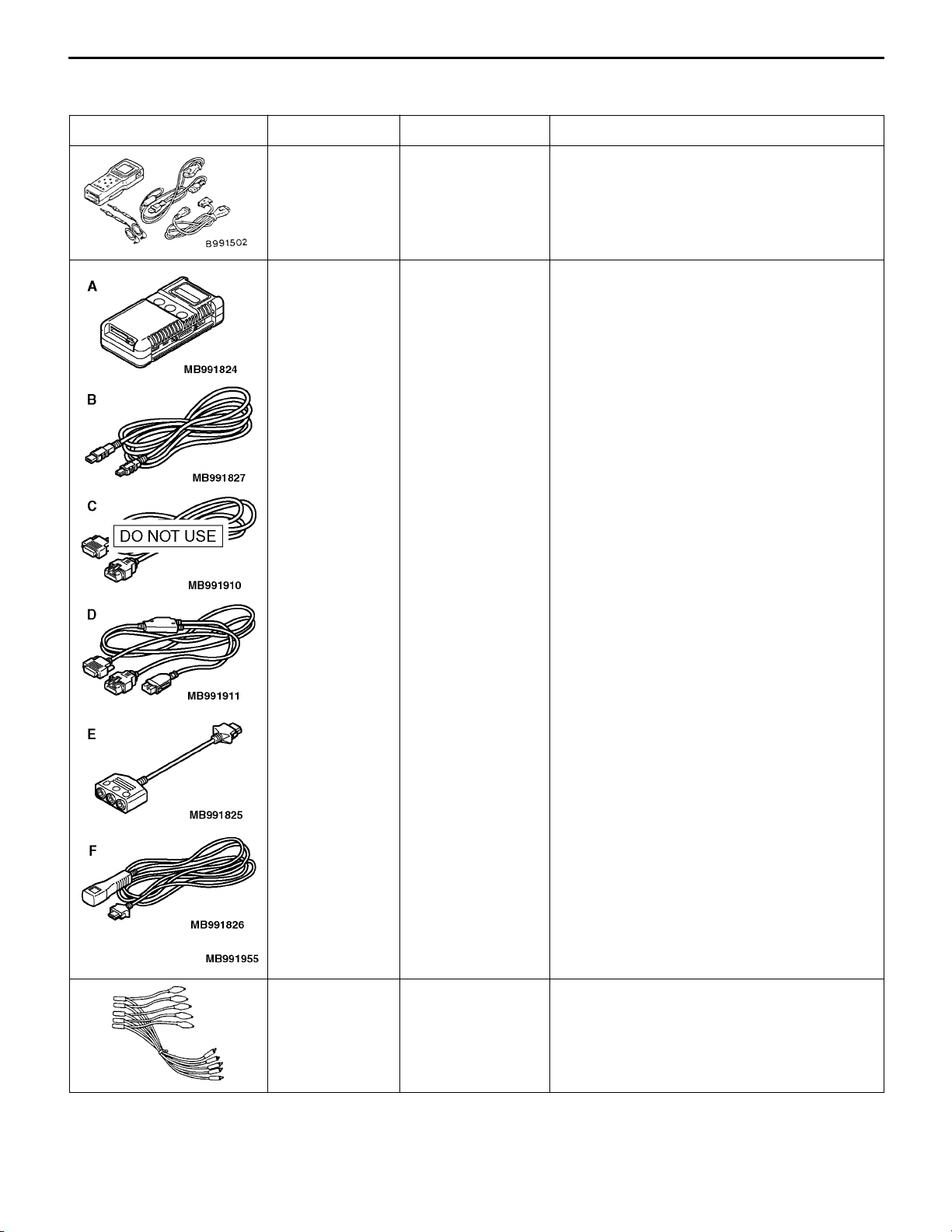
MB991955
A: MB991824
B: MB991827
C: MB991910
D: MB991911
E: MB991825
F: MB991826
M.U.T.-III sub
assembly
A: Vehicle com-
munication interface (V.C.I.)
B: M.U.T.-III
USB cable
C: M.U.T.-III
main harness A
(Vehicles with
CAN communication system)
D: M.U.T.-III
main harness B
(Vehicles without CAN communication system)
E: M.U.T.-III
measurement
adapter
F: M.U.T.-III
trigger harness
M.U.T.-III sub
assembly
D Reading diagnosis code
D MPI system inspection
D Measurement of fuel pressure
D Reading diagnosis code
D MPI system inspection
D Measurement of fuel pressure
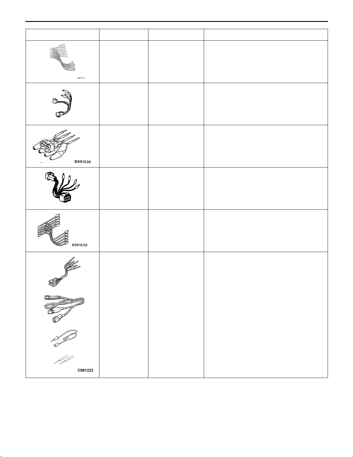
MB991348 Test harness set D Inspection using an oscilloscope
Page 13
13D-8
Too l Us eNameNumber
MB991709 Test harness D Measurement of voltage during
MPI <4G63> ï Special Tools
troubleshooting
D Inspection using an oscilloscope
D Check of idle speed control servo
MD998478 Test harness
(3-pin, triangle)
MB991536 Check harness for
throttle position
sensor adjustment
MD998464 Test harness
(4-pin, square)
MB991658 Test harness D Measurement of voltage during
D Measurement of voltage during
Troubleshooting
D Inspection using an oscilloscope
D Measurement of voltage during
Troubleshooting
D Adjusting of throttle position sensor
D Measurement of voltage during
Troubleshooting
D Inspection of oxygen sensor (front)
Troubleshooting
D Inspection of oxygen sensor (rear)
A
B
C
D
MB991223
A: MB991219
B: MB991220
C: MB991221
D: MB991222
Harness set
A: Test harness
B: LED harness
C: LED harness
adapter
D: Probe
D Check at the ECU terminals
A: Connector pin contact pressure inspection
B: Power circuit inspection
C: Power circuit inspection
D: Commercial tester connection
Page 14
Too l Us eNameNumber
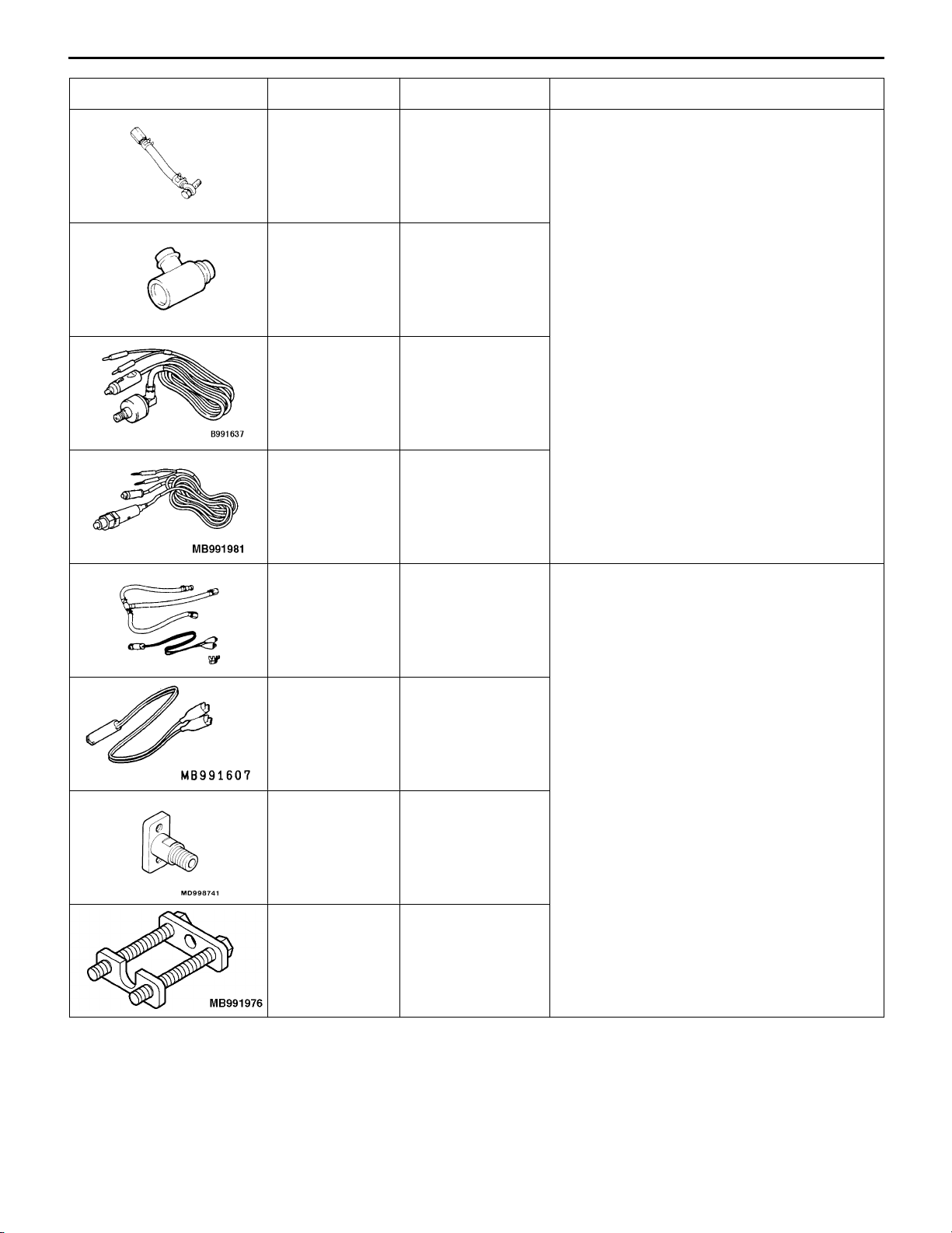
MD998709 Adaptor hose Measurement of fuel pressure
MD998742 Hose adaptor
MB991637 Fuel pressure
MB991981 Fuel pressure
MPI <4G63> ï Special Tools
gauge set
gauge set
13D-9
MB992076 Injector test set Checking the spray condition of injectors
MB991607 Injector test
harness
MD998741 Injector test
adaptor
MB991976 Injector test holder
assembly
Page 15
13D-10
MPI <4G63> ï Troubleshooting
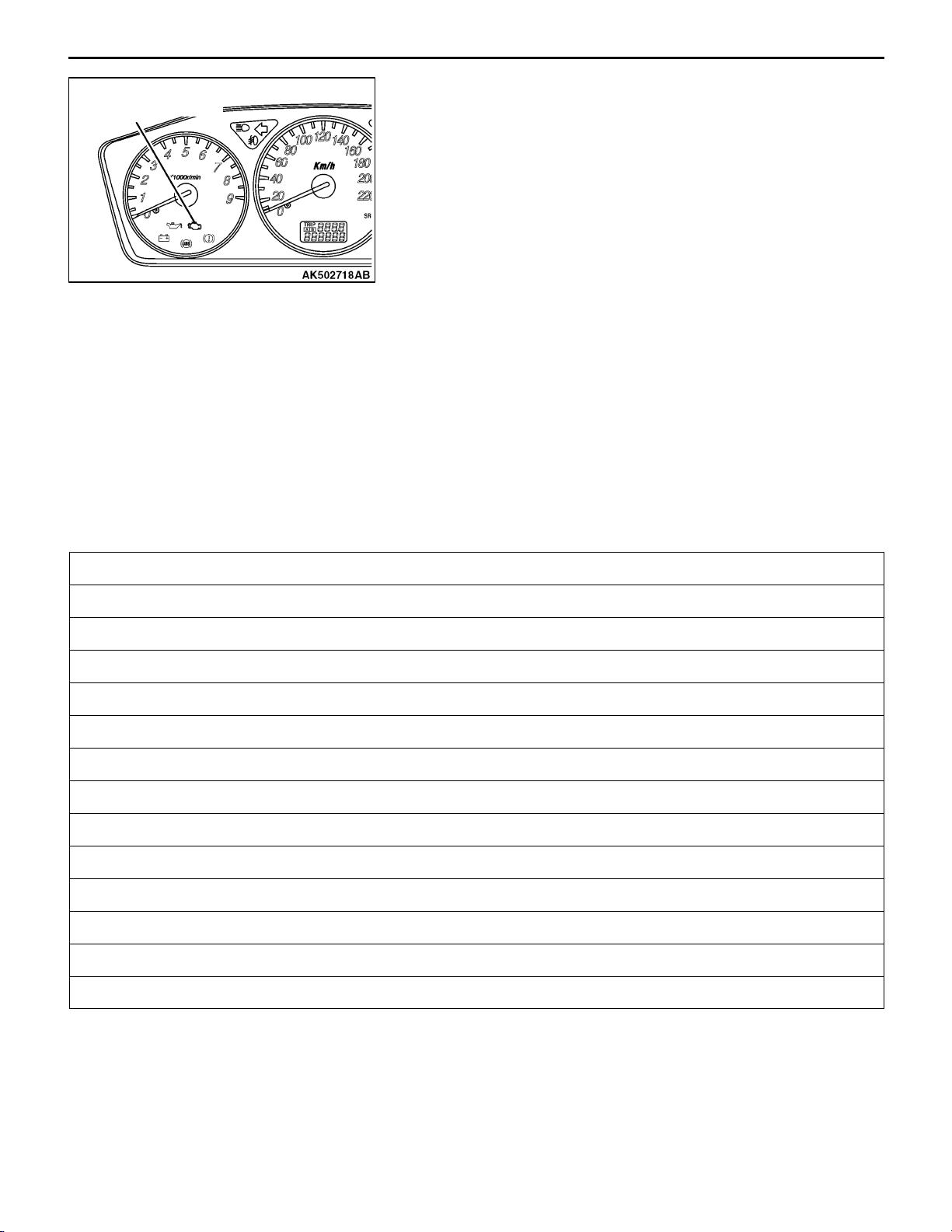
Engine warning lamp
(check engine lamp)
Engine warning lamp inspection items
TROUBLESHOOTING
DIAGNOSIS TROUBLESHOOTING FLOW
Refer to GROUP 00 ï How to Use Troubleshooting/Inspection
Service Point.
NOTE
If the engine-A/T-ECU is replaced, ring antenna with built
in immobilizer-ECU should be replaced, ignition key can be
kept, but must be registered.
DIAGNOSIS FUNCTION
ENGINE WARNING LAMP (CHECK ENGINE LAMP)
If an abnormality occurs in any of the following items related
to the MPI system, the engine warning lamp will illuminate
or flash. If the lamp remains illuminated or if the lamp
illuminates while the engine is running, check the diagnosis
code output.
However, the warning lamp will illuminate as bulb check for
five seconds whenever the ignition switch is turned to the
ON position.
Engine-A/T-ECU
Oxygen sensor (front)
Air flow sensor
Intake air temperature sensor
Throttle position sensor
Engine coolant temperature sensor
Crank angle sensor
Camshaft position sensor
Barometric pressure sensor
Detonation sensor
Ignition coil, power transistor unit
Injector
Immobilizer system
Oxygen sensor (rear)
NOTE
If the engine warning lamp illuminates because of a malfunction of the engine-A/T-ECU, communication
between M.U.T.-II/III and the engine-A/T-ECU is impossible. In this case, the diagnosis code cannot
be read.
Page 16
MPI <4G63> ï Troubleshooting
METHOD OF READING AND ERASING DIAGNOSIS
CODES
Refer to GROUP 00 ï How to Use Troubleshooting/Inspection
Service Points.
INSPECTION USING M.U.T.-II/III DATA LIST AND
ACTUATOR TESTING
1. Carry out inspection by means of the data list and the
actuator test function. If there is an abnormality, check
and repair the chassis harnesses and components.
2. After repairing, re-check using the M.U.T.-II/III and check
that the abnormal input and output have returned to normal
as a result of the repairs.
3. Erase the diagnosis code memory.
4. Remove the M.U.T.-II/III, and then start the engine again
and carry out a road test to confirm that the problem
has disappeared.
13D-11
FAIL-SAFE FUNCTION REFERENCE TABLE
When the main sensor malfunctions are detected by the diagnosis function, the vehicle is controlled
by means of the pre-set control logic to maintain safe conditions for driving.
Malfunctioning item Control contents during malfunction
Air flow sensor 1. Uses the throttle position sensor signal and engine speed signal (crank angle sensor
signal) to take reading of the basic injector drive time and basic ignition timing from
the pre-set mapping.
2. Fixes the ISC servo in the appointed position so idle control is not performed.
Intake air temperature
sensor
Throttle position
sensor (TPS)
Engine coolant
temperature sensor
Camshaft position
sensor
Barometric pressure
sensor
Controls as if the intake air temperature is 25_C.
No increase in fuel injection amount during acceleration due to the throttle position sensor
signal.
Controls as if the engine coolant temperature is 80_C.
Injects fuel into the cylinders in the order 1-3-4-2 with irregular timing.
(However, after the ignition switch is turned to ON, the No. 1 cylinder top dead centre is not
detected at all.)
Controls as if the barometric pressure is 101 kPa.
Detonation sensor Switches the ignition timing from ignition timing for super petrol to ignition timing for standard
petrol.
Ignition coil, power
transistor
Alternator FR terminal Does not control the output of the alternator according to an electrical load. (works as a
Cuts off the fuel supply to cylinders with an abnormal ignition.
normal alternator)
Page 17

13D-12
MPI <4G63> ï Troubleshooting
INSPECTION CHART FOR DIAGNOSIS CODES
Code No. Diagnosis item Reference page
11 Oxygen sensor (front) system 13D-13
12 Air flow sensor system 13D-15
13 Intake air temperature sensor system 13D-16
14 Throttle position sensor system 13D-18
21 Engine coolant temperature sensor system 13D-20
22 Crank angle sensor system 13D-22
23 Camshaft position sensor system 13D-23
24 Vehicle speed signal system 13D-25
25 Barometric pressure sensor system 13D-26
31 Detonation sensor system 13D-28
41 Injector system 13D-29
44 Ignition coil (power transistor) system 13D-30
54 Immobilizer system 13D-31
59 Oxygen sensor (rear) system 13D-32
64 Alternator FR terminal system 13D-34
NOTE
1. Do not replace the engine-A/T-ECU until a through terminal check reveals there are no short/open
circuit.
2. Check that the engine-A/T-ECU earth circuit is normal before checking for the cause of the problem.
Page 18
MPI <4G63> ï Troubleshooting
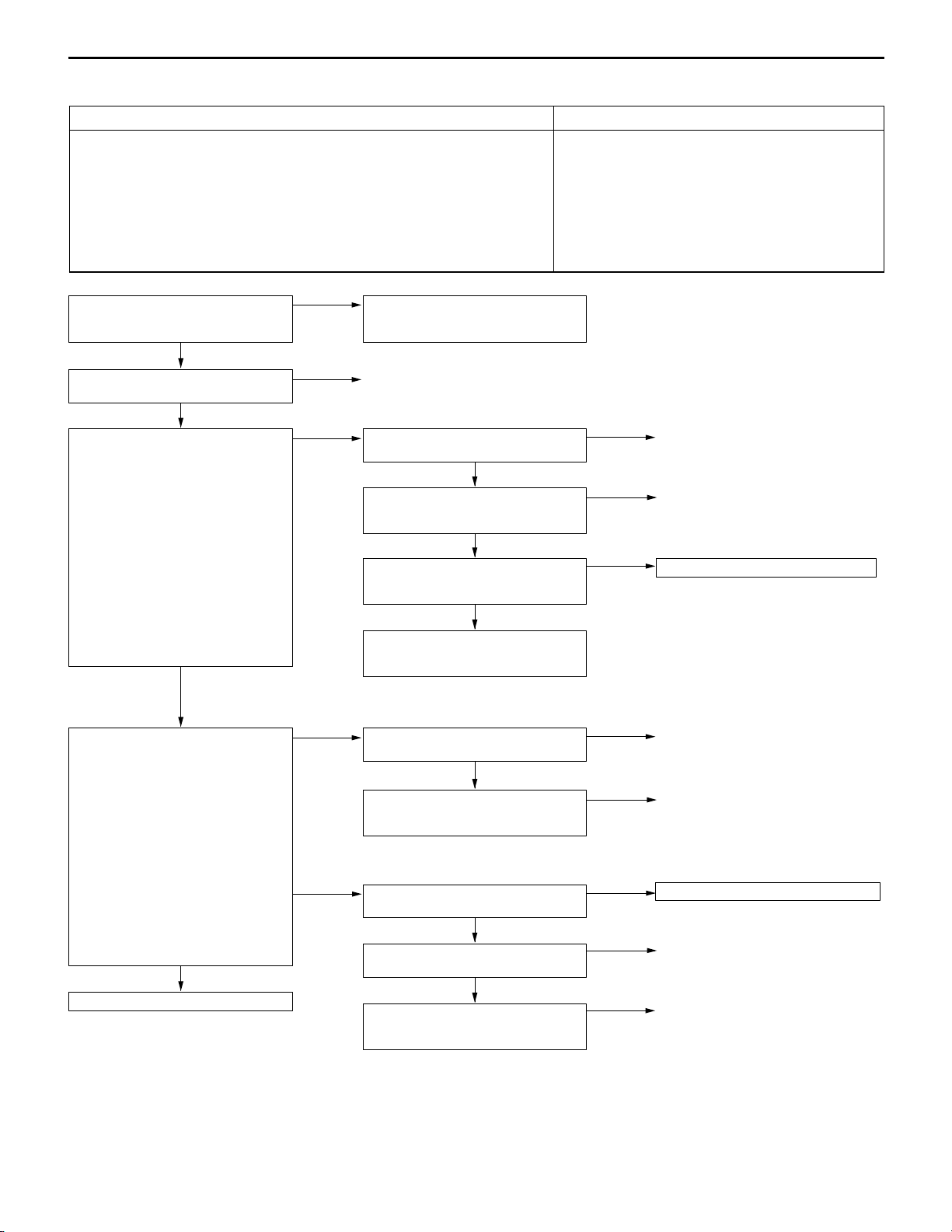
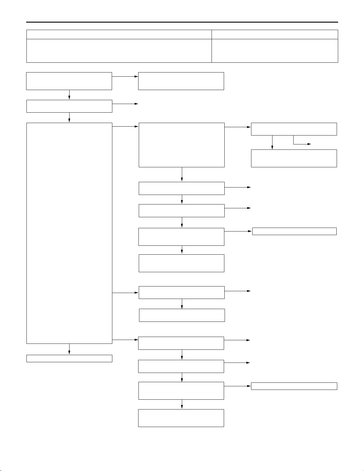
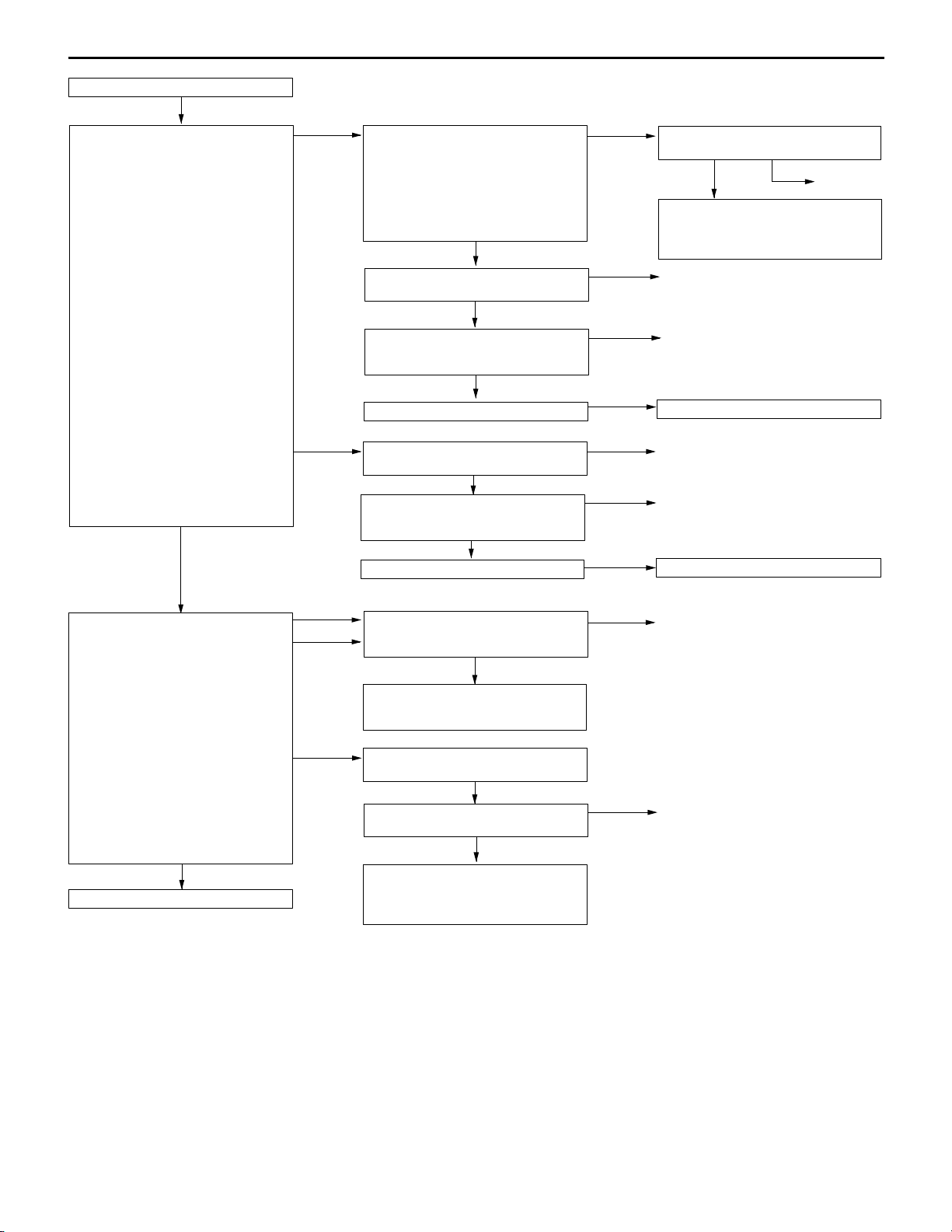
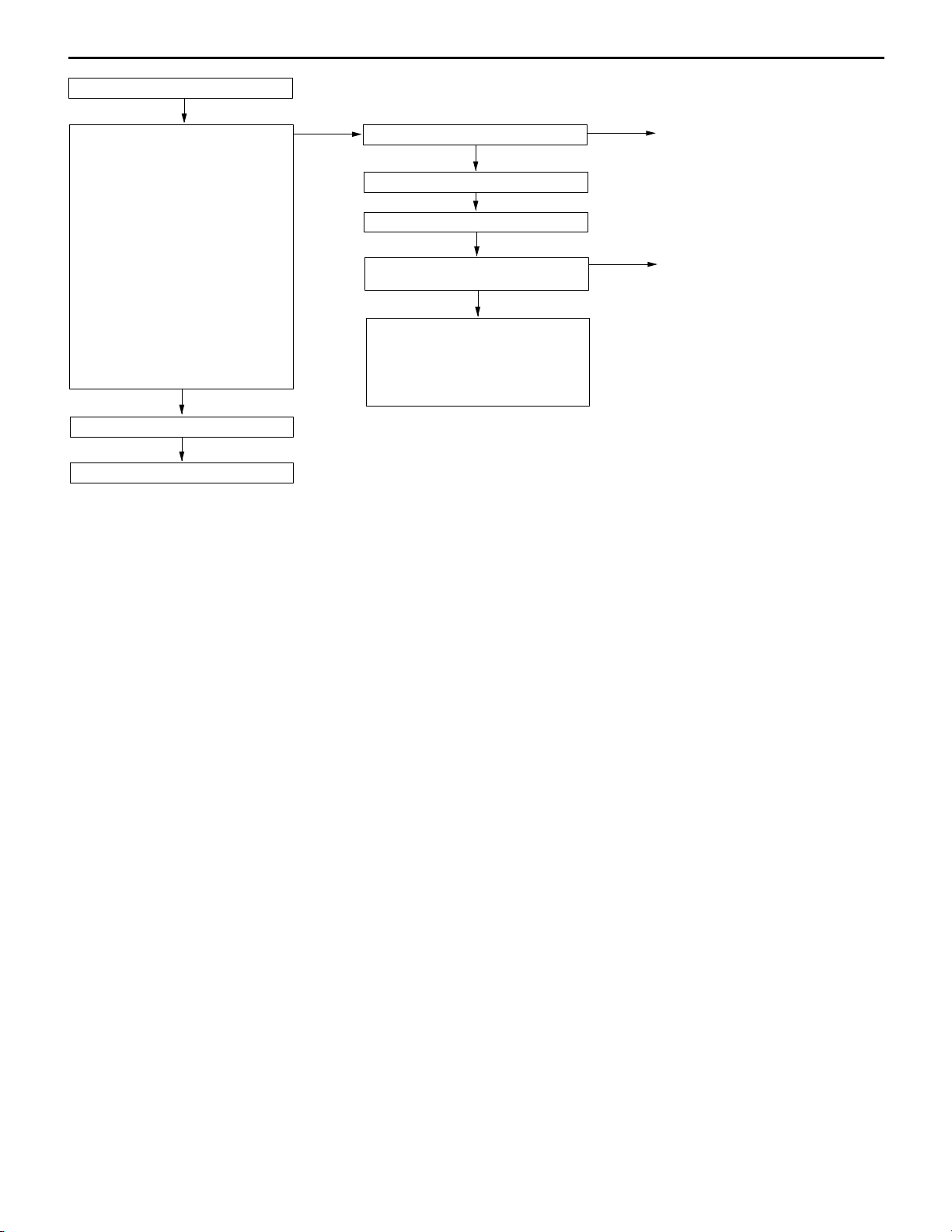
INSPECTION PROCEDURE FOR DIAGNOSIS CODE
Code No. 11 Oxygen sensor (front) system Probable cause
Range of Check
D More than 3 minutes passed after completion of start of engine
D The engine coolant temperature is approximately more than 80_C.
D Intake air temperature 0 ï 55_C.
D The engine speed is more than 1,800 ï 3,500 r/min.
D The volumetric efficiency is 16 ï 60% or more.
Set Conditions
D For 30 seconds, the oxygen sensor output voltage continues to be 0.5 V or
lower, or 0.5 V or higher.
D The Engine-A/T-ECU monitors for this condition once during the drive cycle.
D Malfunction of the oxygen sensor (front)
D Oxygen sensor (front) circuit disconnection,
short-circuit, or connector contact defect.
D Malfunction of the engine-A/T-ECU
13D-13
M.U.T.-II/III Data list
D No. 11 Oxygen sensor (front)
(Refer to P.13D-66.)
NG
Check the following connector:
B-17
OK
Measure at the B-17 oxygen sensor
(front) connector.
D Disconnect connector to measure
at the harness side
D Resistance between terminal No.
2 and earth.
OK: Less than 2 :
OK
Measure at the B-17 oxygen sensor
(front) connector.
D Using the test harness
(MD998464), connect the
connector, and measure at the
pickup harness.
D Engine: After warm-up
(1) Voltage between terminal No. 2
and earth
OK: Less than 0.5 V
(2) Voltage between terminal No. 4
and the earth
D At rapid deceleration from 4,000
r/min
OK: 200 mV or less
D During rapid racing
OK: 600 ï 1,000 mV
OK
To the next page
OK
NG
NG
(1) NG
(2) NG
Intermittent malfunction
(Refer to GROUP 00 ï Points to Note
for Intermittent Malfunctions.)
Repair
Check the following connector:
C-124
OK
Check the harness between the
oxygen sensor (front) and
engine-A/T-ECU.
OK
M.U.T.-II/III Data list
D No. 11 Oxygen sensor (front)
(Refer to P.13D-66.)
OK
Intermittent malfunction
(Refer to GROUP 00 ï Points to Note
for Intermittent Malfunctions.)
Check the following connector:
C-124
OK
Check the harness between the
oxygen sensor (front) and
engine-A/T-ECU.
Check the oxygen sensor (front).
(Refer to P.13D-99.)
OK
Check the following connector:
C-126
OK
Check the harness between the
oxygen sensor (front) and
engine-A/T-ECU.
NG
NG
NG
NG
NG
NG
NG
NG
Repair
Repair
Replace the engine-A/T-ECU.
Repair
Repair
Replace the oxygen sensor (front).
Repair
Repair
Page 19
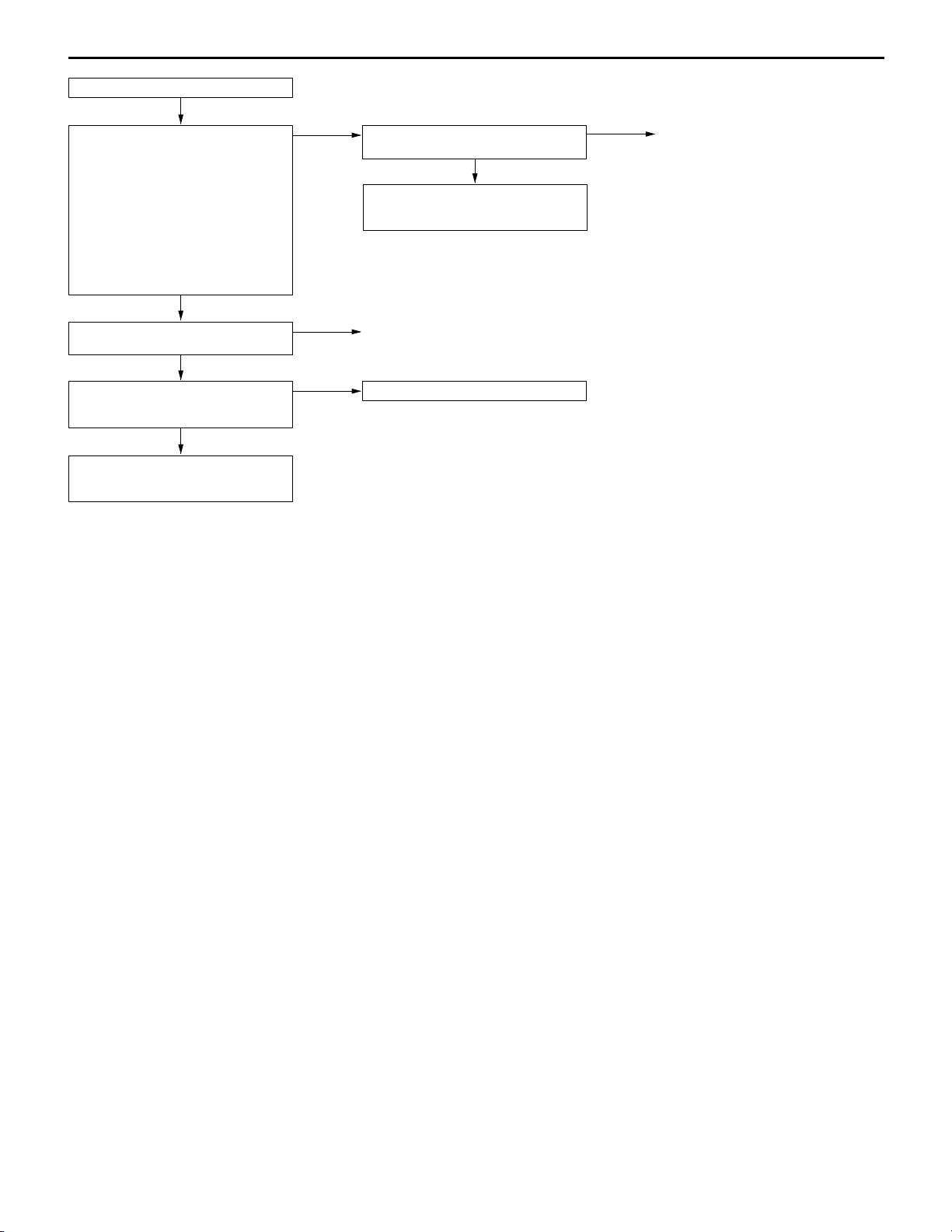
13D-14
From the previous page
OK
Measure at the C-126 engine-A/T-ECU
connector.
D Measure the engine-A/T-ECU
terminal voltage.
D Engine: After warm-up
D Voltage between terminal No. 71
and earth.
D At rapid deceleration from 4,000
r/min
OK: 200 mV or less
D During rapid racing
OK: 600 ï 1,000 mV
OK
Check the following connectors:
C-124, C-126
OK
M.U.T.-II/III Data list
D No. 11 Oxygen sensor (front)
(Refer to P.13D-66.)
OK
Intermittent malfunction
(Refer to GROUP 00 ï Points to Note
for Intermittent Malfunctions.)
MPI <4G63> ï Troubleshooting
NG
NG
NG
Check the following connector:
C-126
OK
Check and repair the harness between
the oxygen sensor (front) and
engine-A/T-ECU.
Repair
Replace the engine-A/T-ECU.
NG
Repair
Page 20
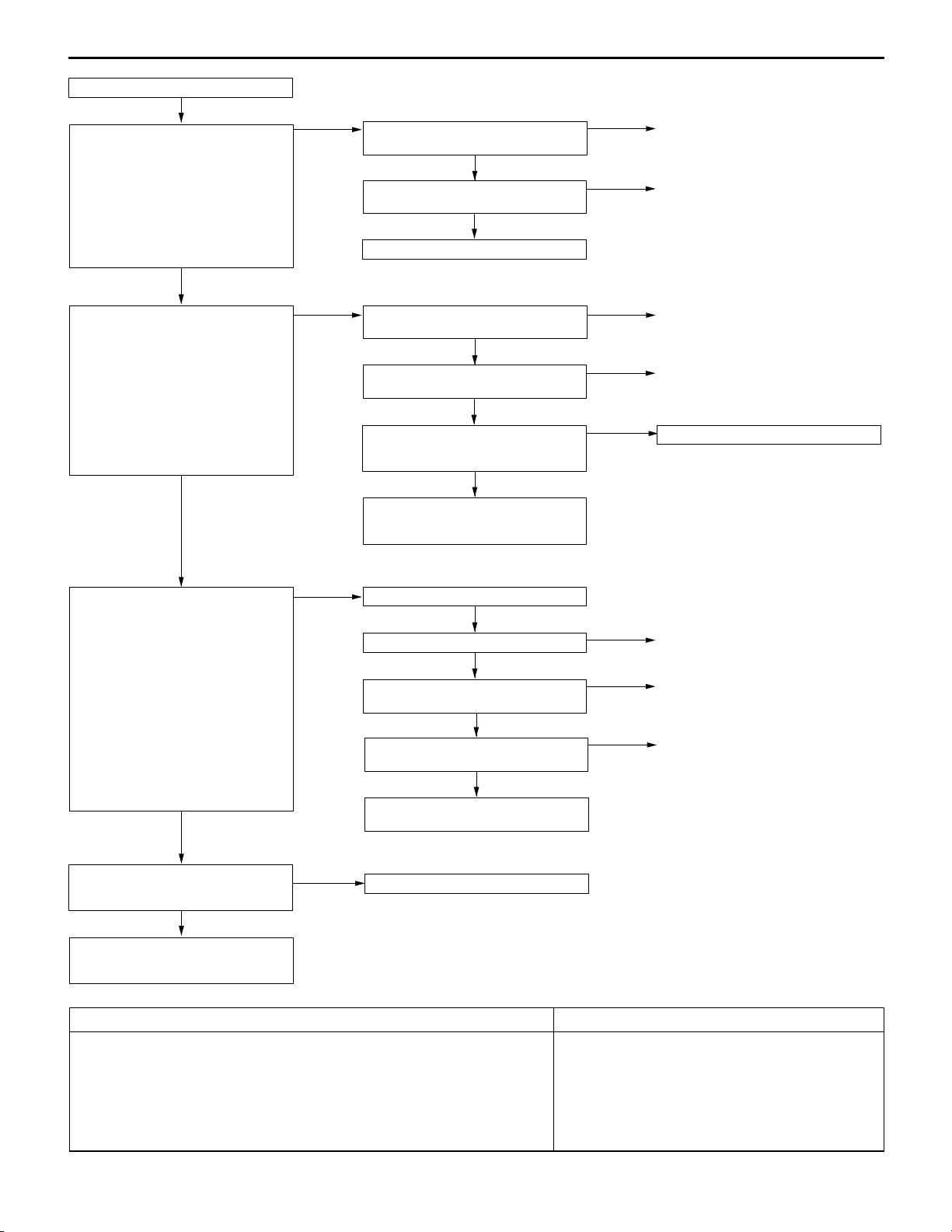
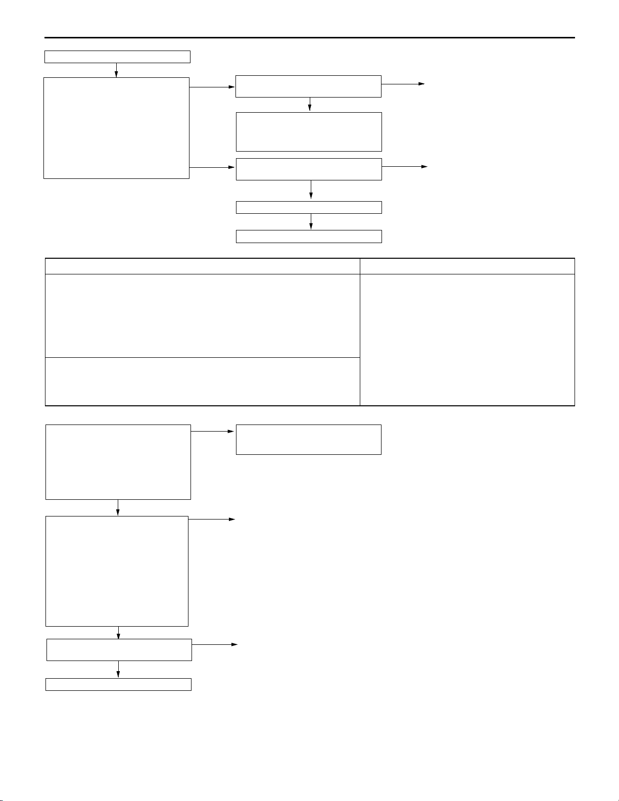
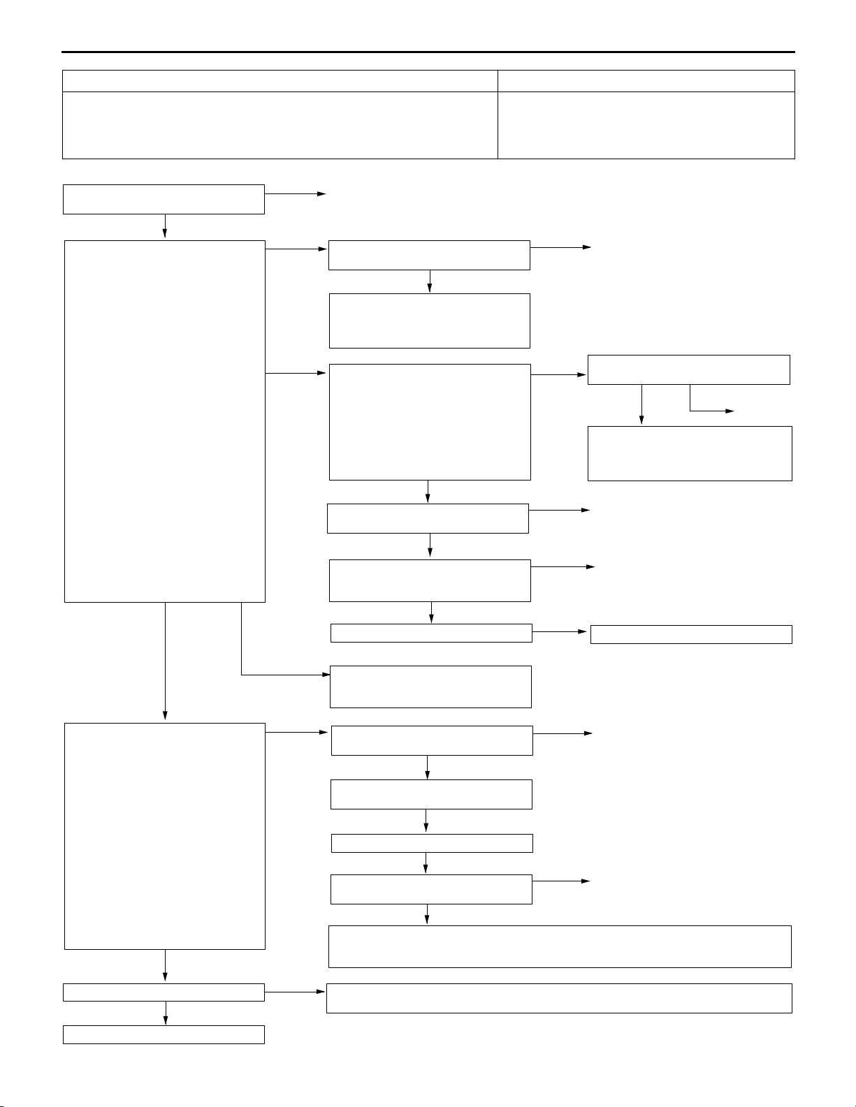
MPI <4G63> ï Troubleshooting
Code No. 12 Air flow sensor system Probable cause
Range of Check
D The engine speed is more than 500 r/min
Set Condition
D The sensor output frequency is less than 3.3 Hz for 4 seconds.
D Malfunction of the air flow sensor
D Air flow sensor circuit disconnection, short-circuit,
or connector contact defect
D Malfunction of the engine-A/T-ECU
13D-15
M.U.T.-II/III Data list
D No. 12 Air flow sensor
(Refer to P.13D-66.)
NG
Check the following connector:
B-08
OK
Measure at the B-08 air flow sensor
connector.
D Disconnect the connector to
measure at the harness side
(1) Voltage between terminal No. 3
and earth
(Ignition switch: ON)
OK: 4.9 ï 5.1 V
(2) Voltage between terminal No. 4
and earth
(Ignition switch: ON)
OK: System voltage
(3) Resistance between terminal No.
5 and earth
OK: Less than 2 :
OK
NG
(1) NG
Intermittent malfunction
(Refer to GROUP 00 ï Points to Note
for Intermittent Malfunctions.)
Repair
Measure at the C-124 engine-A/T-ECU
connector.
D Measure the voltage of the
engine-A/T-ECU terminal.
D Ignition switch: ON
D Voltage between terminal No. 65
and earth.
OK: 4.9 ï 5.1 V
NG
Check the following connector:
C-124
OK
Check the harness between the air
flow sensor and engine-A/T-ECU.
OK
M.U.T.-II/III Data list
D No. 12 Air flow sensor
(Refer to P.13D-66.)
OK
Intermittent malfunction
(Refer to GROUP 00 ï Points to Note
for Intermittent Malfunctions.)
OK
NG
NG
NG
Check the following connector:
C-124
OK
Check and repair the harness between
the air flow sensor and engine-A/TECU.
Repair
Repair
Replace the engine-A/T-ECU.
NG
Repair
To the next page
OK
(2) NG
(3) NG
Check the following connector:
B-16X
OK
Check the harness between the air
flow sensor and engine control relay.
Check the following connector:
C-122
OK
Check the harness between the air
flow sensor and engine-A/T-ECU.
OK
M.U.T.-II/III Data list
D No. 12 Air flow sensor
(Refer to P.13D-66.)
OK
Intermittent malfunction
(Refer to GROUP 00 ï Points to Note
for Intermittent Malfunctions.)
NG
NG
NG
NG
Repair
Repair
Repair
Replace the engine-A/T-ECU.
Page 21
13D-16
From the previous page
OK
Measure at the B-08 air flow sensor
connector.
D Using the test harness
(MB991709), connect the
connector, and measure at the
pickup.
D Ignition switch: ON
D Voltage between terminal No. 7
and earth.
OK: 7 ï 8V
OK
MPI <4G63> ï Troubleshooting
NG
Check the following connector:
C-122
OK
Check the harness between the air
flow sensor and engine-A/T-ECU.
OK
Replace the air flow sensor.
NG
NG
Repair
Repair
Measure at the B-08 air flow sensor
connector.
D Using the test harness
(MB991709), connect the
connector, and measure at the
pickup harness.
D Voltage between terminal No. 7
and earth.
OK: Engine: idle
0 ï 1V
Engine: 3,000 r/min
6 ï 9V
OK
Measure the output waveform at the
B-08 air flow sensor connector (using
an analyzer).
D Using the test harness
(MB991709), connect the
connector, and measure at the
pickup harness.
D Engine: Idle
D Voltage between terminal No. 3
and earth.
OK: Output the waveform as
shown on P.13D-79 (inspection procedure by analyzer), and check that there
is noise in the output waveform.
OK
NG
NG
Check the following connector:
C-122
OK
Check the harness between air flow
sensor and engine-A/T-ECU.
OK
M.U.T.-II/III Data list
D No. 12 Air flow sensor
(Refer to P.13D-66.)
OK
Intermittent malfunction
(Refer to GROUP 00 ï Points to Note
for Intermittent Malfunctions.)
Replace the air flow sensor.
Check the trouble symptom.
NG
Check the following connectors:
B-16X, C-122, C-124
OK
Check the harness between the air
flow sensor and engine control relay.
OK
Check the harness between the air
flow sensor and engine-A/T-ECU.
NG
NG
NG
OK
NG
NG
Repair
Repair
Replace the engine-A/T-ECU.
End
Repair
Repair
M.U.T.-II/III Data list
D No. 12 Air flow sensor
(Refer to P.13D-66.)
OK
Intermittent malfunction
(Refer to GROUP 00 ï Points to Note
for Intermittent Malfunctions.)
NG
Replace the engine-A/T-ECU.
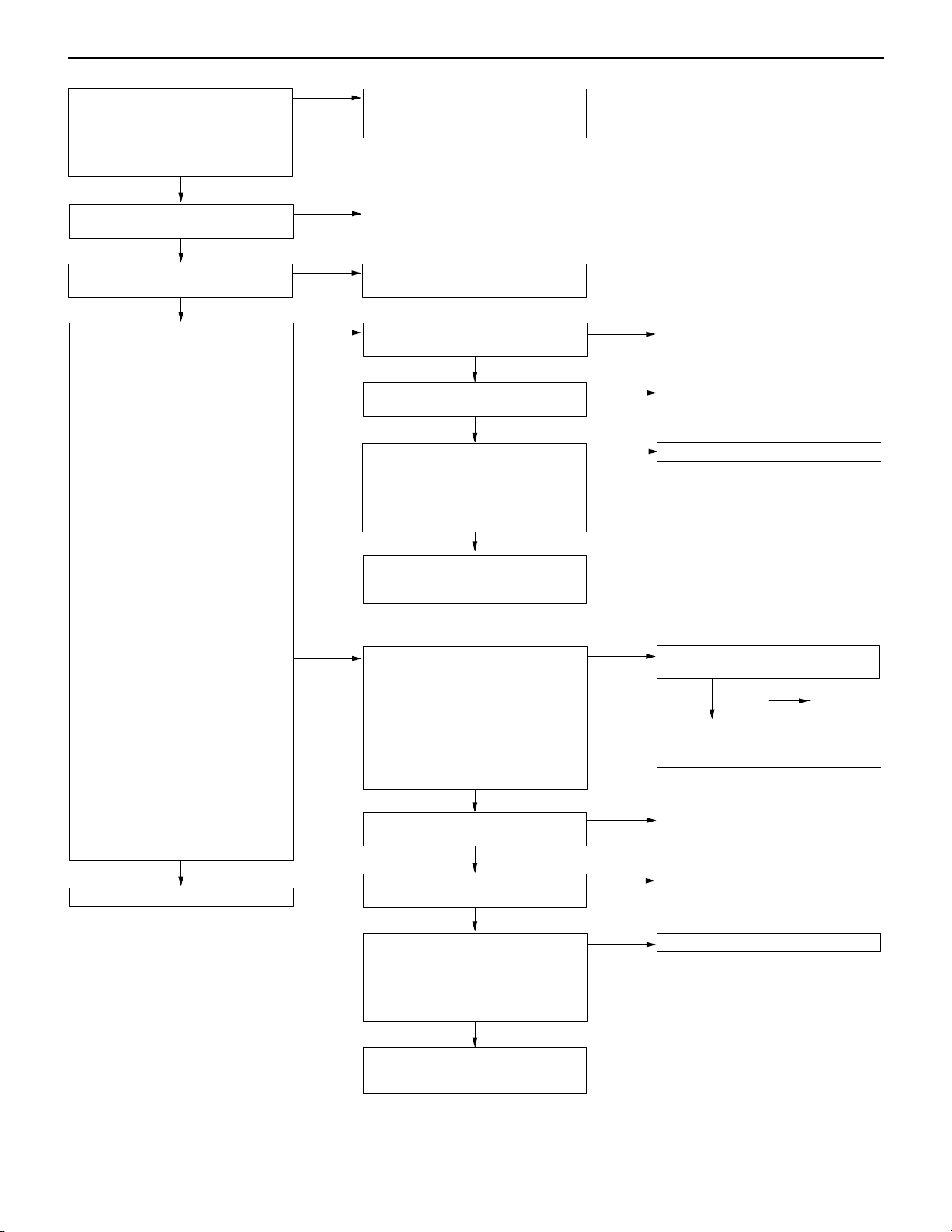
Code No. 13 Intake air temperature sensor system Probable cause
Range of Check
D 60 seconds after the ignition switch is set to the “ON” position, or after the
completion of the start of engine.
Set Conditions
D The sensor output voltage is more than 4.6 V for 4 seconds (Equivalent to intake
air temperature less than ï40_C)
or
D The sensor output voltage is less than 0.2 V for 4 seconds (Equivalent to intake
air temperature of more than 120_C)
D Malfunction of the intake air temperature sensor
D Intake air temperature sensor circuit disconnection,
short-circuit, or connector contact defect
D Malfunction of the engine-A/T-ECU
Page 22
MPI <4G63> ï Troubleshooting
13D-17
M.U.T.-II/III Data list
D No. 13 Intake air temperature
sensor
OK: Ambient temperature (More
or less the same as the air
temperature)
NG
Check the following connector:
B-08
OK
Check the intake air temperature
sensor alone. (Refer to P.13D-97.)
OK
Measure at the B-08 air flow sensor
connector.
D Disconnect the connector to
measure at the harness side
(1) Resistance between terminal No.
5 and earth
OK: Less than 2 :
(2) Voltage between terminal No. 6
and earth
(Ignition switch: ON)
OK: 4.5 ï 4.9 V
OK
NG
NG
(1) NG
Intermittent malfunction
(Refer to GROUP 00 ï Points to Note
for Intermittent Malfunctions.)
Repair
Replace the intake air temperature
sensor.
Check the following connector:
C-122
OK
Check the harness between the air
flow sensor and engine-A/T-ECU.
OK
M.U.T.-II/III Data list
D No. 13 Intake air temperature
sensor
OK: Ambient temperature (More
or less the same as the air
temperature)
OK
Intermittent malfunction
(Refer to GROUP 00 ï Points to Note
for Intermittent Malfunctions.)
NG
NG
NG
Repair
Repair
Replace the engine-A/T-ECU.
To the next page
OK
(2) NG
Measure at the C-124 engine-A/T-ECU
connector.
D Measure the engine-A/T-ECU
terminal voltage.
D Disconnect the B-08 air flow
sensor connector.
D Ignition switch: ON
D Voltage between terminal No. 64
and earth.
OK: 4.5 ï 4.9 V
NG
Check the following connector:
C-124
OK
Check the harness between the air
flow sensor and engine-A/T-ECU.
OK
M.U.T.-II/III Data list
D No. 13 intake air temperature
sensor
OK: Ambient temperature (More
or less the same as air
temperature)
OK
Intermittent malfunction
(Refer to GROUP 00 ï Points to Note
for Intermittent Malfunctions.)
OK
NG
NG
NG
Check the following connector:
C-124
OK
Check and repair the harness between
the air flow sensor and engine-A/TECU.
Repair
Repair
Replace the engine-A/T-ECU.
NG
Repair
Page 23
13D-18
From the previous page
OK
Measure at the B-08 air flow sensor
connector.
D Using the test harness
(MB991709), connecting only
connector terminals No. 5 and
No. 6, and measure at the
pickup harness.
D Ignition switch: ON
D Voltage between terminal No. 6
and earth.
OK: Ambient temperature ï20_C
3.8 ï 4.4 V
Ambient temperature 0_C
3.2 ï 3.8 V
Ambient temperature 20_C
2.3 ï 2.9 V
Ambient temperature 40_C
1.5 ï 2.1 V
Ambient temperature 60_C
0.8 ï 1.4 V
Ambient temperature 80_C
0.4 ï 1.0 V
OK
M.U.T.-II/III Data list
D No. 13 intake air temperature
sensor
OK: Ambient temperature (More
or less the same as the air
temperature)
OK
Intermittent malfunction
(Refer to GROUP 00 ï Points to Note
for Intermittent Malfunctions.)
MPI <4G63> ï Troubleshooting
NG
NG
Check the following connectors:
C-122, C-124
OK
Check and repair the harness between
the air flow sensor and engine-A/TECU.
Replace the engine-A/T-ECU.
NG
Repair
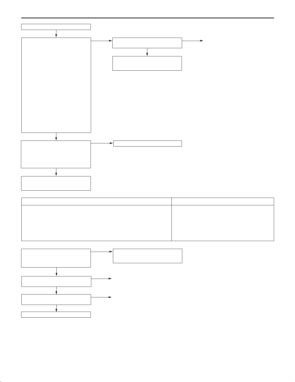
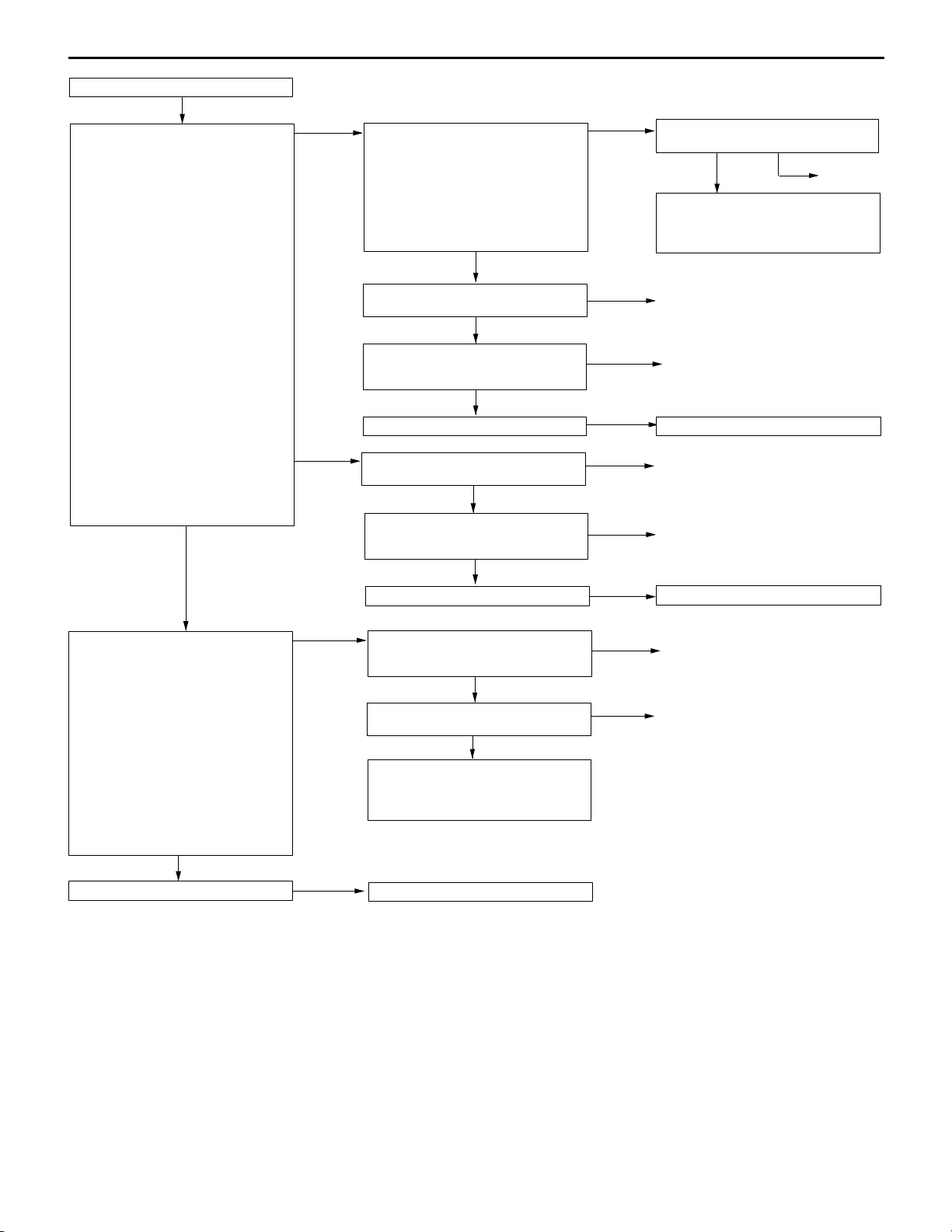
Code No. 14 Throttle position sensor system Probable cause
Range of Check
D 60 seconds after the ignition switch is set to the “ON” position, or after the
completion of start of engine.
Set Conditions
D The sensor output voltage is 4.3 V or more for 4 seconds and volumetric
efficiency 40 % or less.
or
D The sensor output voltage is 0.2 V or less for 2 seconds
M.U.T.-II/III Data list
14 Throttle position sensor
(Refer to P.13D-66, DATA LIST
REFERENCE TABLE.)
NG
Check the throttle position sensor.
(Refer to P.13D-98.)
OK
Check the following connector:
B-06
OK
To the next page
OK
NG
NG
Intermittent malfunction
(Refer to GROUP 00 ï Points to
Note for Intermittent Malfunctions.)
Replace
Repair
D Malfunction of the throttle position sensor
D Improper connector contact, open circuit or
short-circuited harness wire
D Malfunction of the engine-A/T-ECU
Page 24
From the previous page
OK
Measure at throttle position sensor
connector B-06.
D Disconnect the connector and
measure at the harness side.
(1) Voltage between terminal 1 and
earth
(Ignition switch: ON)
OK: 4.9 ï 5.1 V
(2) Resistance between terminal 4
and earth
OK: 2 : or less
MPI <4G63> ï Troubleshooting
(1) NG
Measure at engine-A/T-ECU
connector C-124.
D Measure the voltage at the
engine-A/T-ECU terminals.
D Ignition switch: ON
D Voltage between terminal 46 and
earth
OK: 4.9 ï 5.1 V
NG
Check the following connector:
C-124
OK
Check the harness wire between the
throttle position sensor and the
engine-A/T-ECU.
OK
Check the trouble symptoms.
OK
NG
NG
NG
13D-19
Check the following connector:
C-124
OK
Check the harness wire between the
throttle position sensor and the
engine-A/T-ECU, and repair if
necessary.
Repair
Repair
Replace the engine-A/T-ECU.
NG
Repair
OK
Measure at throttle position sensor
connector B-06.
D Use test harness (MB991536) to
connect the connector, and
measure at the pick-up harness.
D Ignition switch: ON
(1) Voltage between terminal 1 and
earth
OK: 4.9 ï 5.1 V
(2) Voltage between terminal 4 and
earth
OK: 0.5 V or less
(3) Voltage between terminal 2 and
earth
OK: Accelerator pedal fully re-
leased: 0.335 ï 0.935 V
Accelerator pedal fully depressed: 4.4 ï 5.3 V
OK
To the next page
(2) NG
(1) NG
(2) NG
(3) NG
Check the following connector:
C-124
OK
Check the harness wire between the
throttle position sensor and the
engine-A/T-ECU.
OK
Check the trouble symptoms.
Check the following connector:
C-124
OK
Check the harness wire between the
throttle position sensor and the
engine-A/T-ECU.
Adjust the throttle position sensor.
(Refer to P.13D-98.)
Check the following connector:
C-126
OK
Check the harness wire between the
throttle position sensor and the
engine-A/T-ECU, and repair if
necessary.
NG
NG
NG
NG
NG
Repair
Repair
Replace the engine-A/T-ECU.
Repair
Repair
Page 25
13D-20
From the previous page
OK
Measure at the engine-A/T-ECU
connector C-126
D Measure voltage at the
engine-A/T-ECU terminal.
D Ignition switch: ON
D Voltage between terminal 78 and
earth
OK: Accelerator pedal fully re-
leased: 0.335 ï 0.935 V
Accelerator pedal fully depressed: 4.4 ï 5.3 V
MPI <4G63> ï Troubleshooting
NG
OK
Check the following connector:
C-126
OK
Check the harness wire between the
throttle position sensor and the
engine-A/T-ECU, and repair if
necessary.
Check the following connectors:
C-124, C-126
OK
Check the trouble symptoms.
NG
Replace the engine-A/T-ECU.
NG
NG
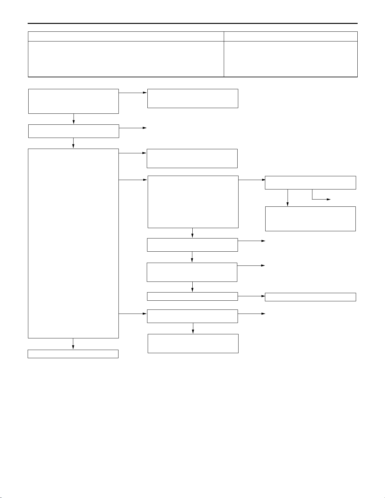
Code No. 21 Engine coolant temperature sensor system Probable cause
Range of Check
D 60 seconds after the ignition switch is set to the “ON” position, or after the
completion of start of engine.
Set Conditions
D The sensor output voltage is 4.6 V or more for 4 seconds (equivalent to
ï45_C or lower of engine coolant temperature)
or
D The sensor output voltage is 0.1 V or less for 4 seconds (equivalent to
140_C or higher of engine coolant temperature)
Range of Check
D Engine: After starting
Set Condition
D The engine coolant temperature has reduced from over 40_C to less than
40_C, and that condition has lasted for five minutes or more.
D Malfunction of the engine coolant temperature
sensor
D Open or short circuit in the engine coolant
temperature sensor circuit or loose connector
contact
D Malfunction of the engine-A/T-ECU
Repair
Repair
M.U.T.-II/III Data list
21 Engine coolant temperature
sensor
OK: When the engine is cold,
the temperature is roughly
the same as ambient temperature. If warm, it is 80 ï
120_C.
NG
Measure at engine coolant
temperature sensor connector
B-111.
D Disconnect the connector and
measure at the sensor side.
D Resistance between terminals 1
and 2
OK: At 20_C of engine coolant
temperature: 2.1 ï 2.7 k:
At 80_C of engine coolant
temperature:
0.26 ï 0.36 k:
OK
Check the following connector:
B-111
OK
To the next page
OK
NG
NG
Intermittent malfunction
(Refer to GROUP 00 ï Points to
Note for Intermittent Malfunctions.)
Replace
Repair
Page 26
From the previous page
OK
Measure at engine coolant
temperature sensor connector B-111.
D Disconnect the connector and
measure at the harness side.
(1) Voltage between terminal 1 and
earth
(Ignition switch: ON)
OK: 4.5 ï 4.9 V
(2) Resistance between terminal 2
and earth
OK: 2 : or less
OK
MPI <4G63> ï Troubleshooting
(1) NG
(2) NG
Measure at engine-A/T-ECU
connector C-124.
D Measure the voltage at the
engine-A/T-ECU terminal.
D Disconnect connector B-111.
D Ignition switch: ON
D Voltage between terminal 44 and
earth
OK: 4.5 ï 4.9 V
NG
Check the following connector:
C-124
OK
Check the harness wire between the
engine coolant temperature sensor
and the engine-A/T-ECU.
OK
Check the trouble symptoms.
Check the following connector:
C-124
OK
Check the harness wire between the
engine coolant temperature sensor
and the engine-A/T-ECU.
OK
Check the trouble symptoms.
OK
NG
NG
NG
NG
NG
NG
13D-21
Check the following connector:
C-124
OK
Check the harness wire between the
engine coolant temperature sensor
and the engine-A/T-ECU, and repair
if necessary.
Repair
Repair
Replace the engine-A/T-ECU.
Repair
Repair
Replace the engine-A/T-ECU.
NG
Repair
Measure at engine coolant
temperature sensor connector B-111.
D Use test harness (MB991658) to
connect the connector, and
measure at the pick-up harness.
D Ignition switch: ON
D Voltage between terminal 1 and
earth
OK: At 0_C of engine coolant
temperature: 3.2 ï 3.8 V
At 20_C of engine coolant
temperature: 2.3 ï 2.9 V
At 40_C of engine coolant
temperature: 1.3 ï 1.9 V
At 80_C of engine coolant
temperature: 0.3 ï 0.9 V
OK
Check the trouble symptoms.
NG
NG
Check the engine coolant
temperature sensor.
(Refer to P.13D-98.)
OK
Check the following connector:
C-124
OK
Check the harness wire between the
engine coolant temperature sensor
and the engine-A/T-ECU, and repair
if necessary.
Replace the engine-A/T-ECU.
NG
NG
Repair
Repair
Page 27
13D-22
MPI <4G63> ï Troubleshooting
Code No. 22 Crank angle sensor system Probable cause
Range of Check
D Engine is cranking
Set Condition
D Sensor output voltage does not change for 4 seconds (no pulse signal input).
D Malfunction of the crank angle sensor.
D Open or short circuit in the crank angle sensor
circuit or loose connector contact.
D Malfunction of the engine-A/T-ECU
M.U.T.-II/III Data list
22 Crank angle sensor
OK: Refer to P.13D-66, DATA
LIST REFERENCE TABLE.
NG
Check the following connector:
B-116
OK
Measure at the crank angle sensor
connector B-116.
D Disconnect the connector and
measure at the harness side.
(1) The resistance between terminal
1 and earth
OK: 2 : or less
(2) The voltage between terminal 2
and earth
(Ignition switch: ON)
OK: 4.9 ï 5.1 V
(3) The voltage between terminal 3
and earth
(Ignition switch: ON)
OK: System voltage
OK
NG
(1) NG
(2) NG
Intermittent malfunction
(Refer to GROUP 00 ï Points to
Note for Intermittent Malfunctions.)
Repair
Check the harness between the
crank angle sensor and earth, and
repair if necessary.
Measure at the engine-A/T-ECU
connector C-124.
D Measure the voltage at the
engine-A/T-ECU terminal.
D Disconnect the connector B-116
D Ignition switch: ON
D The voltage between terminal 45
and earth
OK: 4.9 ï 5.1 V
NG
Check the following connector:
C-124
OK
Check the harness wire between the
crank angle sensor and the
engine-A/T-ECU.
OK
Check the trouble symptoms.
OK
NG
NG
NG
Check the following connector:
C-124
OK
Check the harness wire between the
crank angle sensor and the
engine-A/T-ECU, and repair if
necessary.
Repair
Repair
Replace the engine-A/T-ECU.
NG
Repair
To the next page
OK
(3) NG
Check the following connector:
B-16X
OK
Check the harness wire between the
crank angle sensor and the engine
control relay, and repair if necessary.
NG
Repair
Page 28
From the previous page
OK
Use an analyzer to measure the
output waveform at the crank angle
sensor connector B-116.
D Use the test harness
(MD998478) to connect the
connector, and measure at the
pick-up harness side.
D Engine: Idling
D The voltage between terminal 2
and earth
OK: A normal waveform should
be displayed as described
on P.13D-81 (Inspection
Procedure Using an Analyzer). Its maximum value
should be 4.8 V or more,
and its minimum value
should be 0.6 V or less
with no noise in waveform.
OK
Check the trouble symptoms.
NG
Replace the engine-A/T-ECU.
MPI <4G63> ï Troubleshooting
NG
Check the crank angle sensor vane.
OK
Replace the crank angle sensor.
Check the trouble symptoms.
NG
Check the following connectors:
B-16X, C-124
OK
Check the harness wires between
the crank angle sensor and the
engine-A/T-ECU, crank angle sensor
and the engine control relay, and the
crank angle sensor and earth. Then,
repair if necessary.
NG
NG
13D-23
Replace
Repair
Page 29
13D-24
MPI <4G63> ï Troubleshooting
Code No. 23 Camshaft position sensor system Probable cause
Range of Check
D During engine cranking and driving
Set Condition
D The sensor output voltage does not change for 4 seconds (no pulse signal
input).
D Malfunction of the camshaft position sensor
D Open or short circuit in the camshaft position
sensor circuit or loose connector contact.
D Malfunction of the engine-A/T-ECU
Check the following connector:
B-107
OK
Measure at camshaft position sensor
connector B-107.
D Disconnect the connector and
measure at the harness side.
(1) The voltage between terminal 3
and earth
(Ignition switch: ON)
OK: System voltage
(2) The voltage between terminal 2
and earth
(Ignition switch: ON)
OK: 4.9 ï 5.1 V
(3) The resistance between terminal
1 and earth
OK: 2 : or less
OK
NG
(1) NG
(2) NG
Repair
Check the following connector:
B-16X
OK
Check the harness wire between the
camshaft position sensor connector
and the engine control relay, and
repair if necessary.
Measure at the engine-A/T-ECU
connector C-124.
D Measure the voltage at the
engine-A/T-ECU terminal.
D Disconnect connector B-107.
D Ignition switch: ON
D The voltage between terminal 56
and earth
OK: 4.9 ï 5.1 V
NG
Check the following connector:
C-124
OK
Check the harness wire between the
intermediate connector and the
engine-A/T-ECU.
OK
Check the trouble symptoms.
NG
OK
NG
NG
NG
Repair
Check the following connector:
C-124
OK
Check the harness wire between the
camshaft position sensor connector
and the engine-A/T-ECU, and repair if
necessary.
Repair
Repair
Replace the engine-A/T-ECU.
NG
Repair
Use an analyzer to measure the
output waveform at camshaft position
sensor connector B-107.
D Use test harness (MB991709) to
connect the connector, and
measure at the pick-up harness.
D Engine: Idling
D The voltage between terminal 2
and earth
OK: A normal waveform should
be displayed as described
on P.13D-81 (Inspection
Procedure Using an Analyzer), its maximum value
should be 4.8 V or more,
and its minimum value
should be 0.6 V or less
with no noise in waveform.
OK
Check the trouble symptoms.
NG
Replace the engine-A/T-ECU.
(3) NG
NG
OK
Check the harness wire between the
camshaft position sensor connector
and earth, and repair if necessary.
Check the camshaft position sensing
cylinder.
OK
Replace the camshaft position
sensor.
Check the trouble symptoms.
NG
Check the following connectors:
B-16X, C-124
OK
Check the harness wires between the camshaft position sensor connector and the
engine-A/T-ECU, the camshaft position sensor connector and the engine control relay,
and the camshaft position sensor connector and earth. Then, repair if necessary.
Intermittent malfunction
(Refer to GROUP 00 ï Points to Note for Intermittent Malfunctions.)
NG
NG
Replace
Repair
Page 30
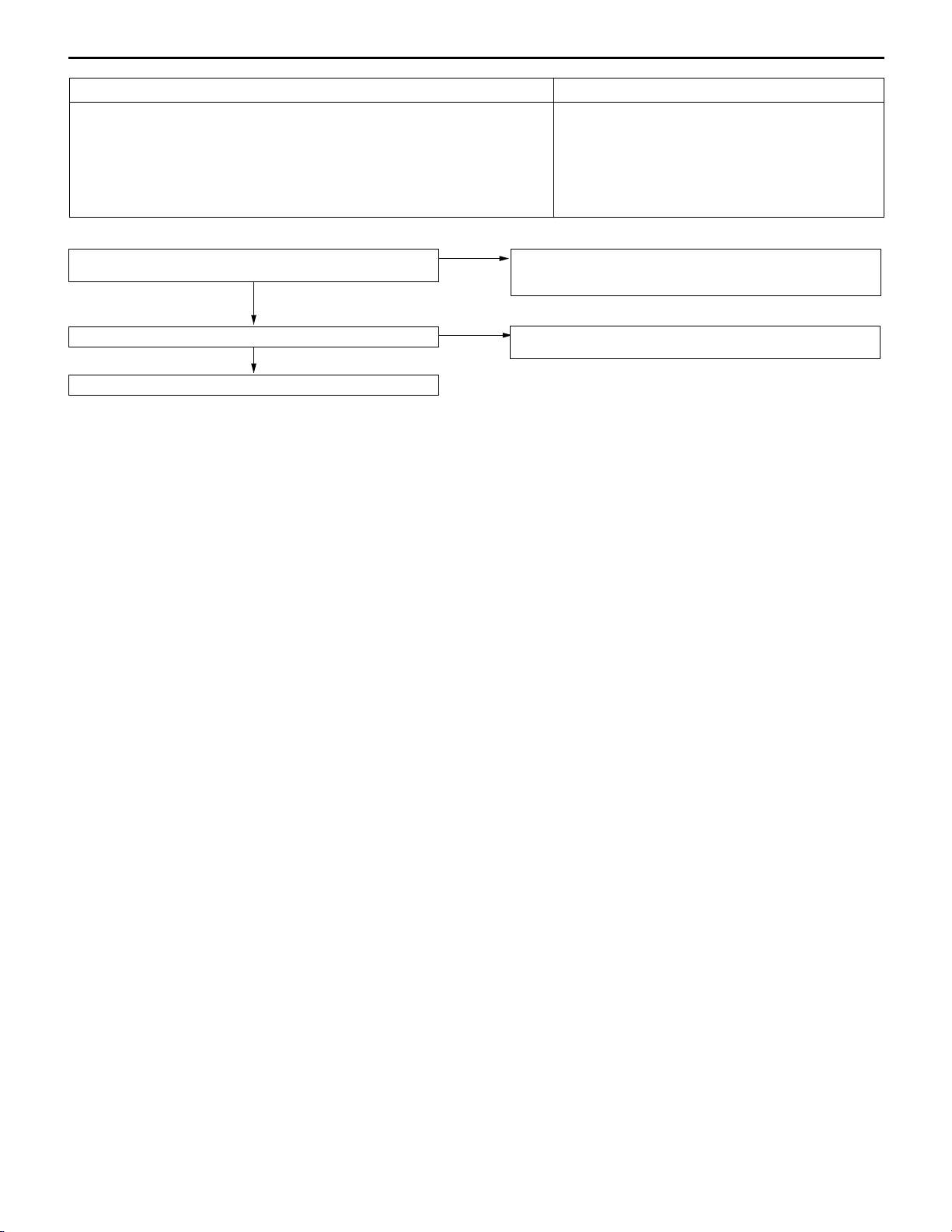
MPI <4G63> ï Troubleshooting
Code No. 24 Vehicle speed signal system Probable cause
Range of Check
D 60 seconds after the ignition switch is set to the “ON” position, or after the
completion of start of engine.
D The engine speed is more than 2,300 r/min.
D Volumetric efficiency 50 % or more
Set Condition
D The vehicle speed signal does not change for 4 seconds (no pulse signal
input.)
D Malfunction of the output shaft speed sensor
D Open or short circuit in the output shaft speed
sensor circuit or loose connector contact
D Malfunction of the engine-A/T-ECU
13D-25
M.U.T.-II/III Self-Diag code
D Is diagnosis code of automatic transmission system output?
NO
Check the trouble symptoms.
NG
Replace the engine-A/T-ECU.
YES
OK
D Automatic transmission system check
(Refer to GROUP 23B ï Troubleshooting ï Inspection
chart for diagnosis codes)
Intermittent malfunction. (Refer to GROUP 00 ï Points to Note
for Intermittent Malfunctions.)
Page 31

13D-26
MPI <4G63> ï Troubleshooting
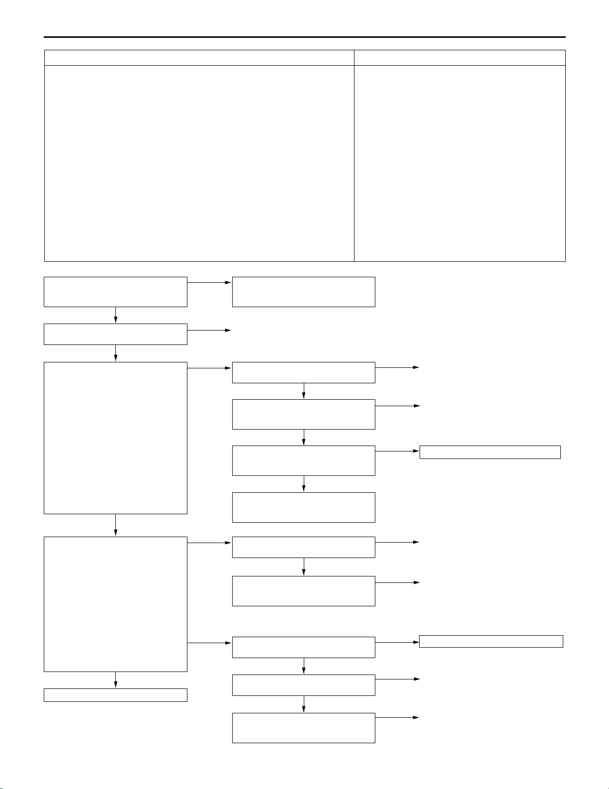
Code No. 25 Barometric pressure sensor system Probable cause
Range of Check
D 60 seconds after the ignition switch is set to the “ON” position, or after the
completion of start of engine.
D Battery voltage 8 V or more.
Set Conditions
D The sensor output voltage is more than 4.5 V for 4 seconds (Equivalent to
air pressure of more than 114 kPa)
or
D The sensor output voltage is less than 0.2 V for 4 seconds (Equivalent to air
pressure of less than 5 kPa)
D Malfunction of the barometric pressure sensor
D Barometric pressure sensor circuit disconnection,
short-circuit, or connector contact defect
D Malfunction of the engine-A/T-ECU
M.U.T.-II/III Data list
D No. 25 Barometric pressure
sensor (Refer to P.13D-66.)
NG
Check the following connector:
B-08
OK
Measure at the B-08 air flow sensor
connector.
D Disconnect the connector to
measure at the harness side
(1) Voltage between terminal No. 1
and earth
(Ignition switch: ON)
OK: 4.9 ï 5.1 V
(2) Resistance between terminal No.
5 and earth.
OK: Less than 2 :
OK
NG
(1) NG
Intermittent malfunction
(Refer to GROUP 00 ï Points to Note
for Intermittent Malfunctions.)
Repair
Measure at the C-124 engine-A/T-ECU
connector.
D Measure the engine-A/T-ECU
terminal voltage.
D Ignition switch: ON
D Voltage between terminal No. 46
and earth
OK: 4.9 ï 5.1 V
NG
Check the following connector:
C-124
OK
Check the harness between the air
flow sensor and engine-A/T-ECU.
OK
M.U.T.-II/III Data list
D No. 25 Barometric pressure
sensor (Refer to P.13D-66.)
OK
Intermittent malfunction
(Refer to GROUP 00 ï Points to Note
for Intermittent Malfunctions.)
OK
NG
NG
NG
Check the following connector:
C-124
OK
Check and repair the harness between
the air flow sensor and engine-A/TECU.
Repair
Repair
Replace the engine-A/T-ECU.
NG
Repair
To the next page
OK
(2) NG
Check the following connector:
C-122
OK
Check the harness between the air
flow sensor and engine-A/T-ECU.
OK
M.U.T.-II/III Data list
D No. 25 Barometric pressure
sensor (Refer to P.13D-66.)
OK
Intermittent malfunction
(Refer to GROUP 00 ï Points to Note
for Intermittent Malfunctions.)
NG
NG
NG
Repair
Repair
Replace the engine-A/T-ECU.
Page 32

From the previous page
OK
Measure at the B-08 air flow sensor
connector.
D Using the test harness
(MB991709), connect only
connector terminals No. 1, No. 2,
and No. 5, and measure at the
pickup harness.
D Ignition switch: ON
(1) Voltage between terminal No. 1
and earth
OK: 4.9 ï 5.1 V
(2) Voltage between terminal No. 5
and earth
OK: Less than 0.5 V
(3) Voltage between terminal No. 2
and earth
OK: High 0 m 3.8 ï 4.2 V
High 600 m 3.5 ï 3.9 V
High 1,200 m 3.3 ï 3.7 V
High 1,800 m 3.0 ï 3.4 V
OK
MPI <4G63> ï Troubleshooting
(1) NG
(2) NG
(3) NG
Check the following connector:
C-124
OK
Check and repair the harness between
the air flow sensor and engine-A/TECU.
Check the following connector:
C-122
OK
Check and repair the harness between
the air flow sensor and engine-A/TECU.
Check the following connector:
C-124
OK
Check the harness between the air
flow sensor and engine-A/T-ECU.
OK
Replace the air flow sensor.
NG
NG
NG
NG
13D-27
Repair
Repair
Repair
Repair
Measure at the C-124 engine-A/T-ECU
connector.
D Measure the engine-A/T-ECU
terminal voltage.
D Ignition switch: ON
D Voltage between terminal No. 55
and earth.
OK: High 0 m 3.8 ï 4.2 V
High 600 m 3.5 ï 3.9 V
High 1,200 m 3.3 ï 3.7 V
High 1,800 m 3.0 ï 3.4 V
OK
Check the following connectors:
C-122, C-124
OK
M.U.T.-II/III Data list
D No. 25 Barometric pressure
sensor (Refer to P.13D-66.)
OK
Intermittent malfunction
(Refer to GROUP 00 ï Points to Note
for Intermittent Malfunctions.)
NG
NG
NG
Check the following connector:
C-124
OK
Check and repair the harness between
the air flow sensor and engine-A/TECU.
Repair
Replace the engine-A/T-ECU.
NG
Repair
Page 33

13D-28
MPI <4G63> ï Troubleshooting
Code No. 31 Detonation sensor system Probable cause
Range of Check
D 60 seconds after the ignition switch is set to the “ON” position, or after the
completion of start of engine.
D The engine speed is more than 2,500 r/min.
D Volumetric efficiency 30 % or more
Set Condition
D Changes in sensor output voltage (detonation sensor peak voltage per 1/2
crankshaft rotation) in 200 consecutive cycles are 0.078 V or less.
D Malfunction of the detonation sensor
D Open or short circuit in the detonation sensor
circuit or loose connector contact
D Malfunction of the engine-A/T-ECU
Check the following connector: B-117
OK
Measure at the detonation sensor connector B-117.
D Disconnect the connector and measure at the harness
side.
D The resistance between terminal 2 and earth
OK: 2 : or less
OK
Check the following connector: C-126
OK
Check the harness wire between the detonation sensor and
the engine-A/T-ECU.
OK
Check the trouble symptoms.
NG
Replace the detonation sensor.
Check the trouble symptoms.
NG
Replace the engine-A/T-ECU.
NG
NG
NG
NG
OK
Repair
Check the harness wire between the detonation sensor and
earth, and repair if necessary.
Repair
Repair
Intermittent malfunction (Refer to GROUP 00 ï Points to Note
for Intermittent Malfunctions.)
Page 34

MPI <4G63> ï Troubleshooting
Code No. 41 Injector system Probable cause
Range of Check
D Fuel cut and injector not in forced drive (actuator test) mode.
D The engine speed is 50 ï 1,000 r/min
D The throttle position sensor output voltage is 1.15 V or less.
Set Condition
D Surge voltage of injector coil is not detected for 4 seconds.
D Malfunction of the injector
D Improper connector contact, open circuit or short-cir-
cuited harness wire of the injector circuit
D Malfunction of the engine-A/T-ECU
13D-29
M.U.T.-II/III Actuator Test
01 No. 1 injector
02 No. 2 injector
03 No. 3 injector
04 No. 4 injector
OK: The idling condition should change
NG
Check the following connectors:
B-02, B-03, B-04, B-05
OK
Check the injector. (Refer to P.13D-101.)
OK
Measure at the injector connector B-02, B-03, B-04, B-05.
D Disconnect the connector, and measure at the harness side.
D Voltage between 1 and earth (Ignition switch: ON)
OK: System voltage
OK
Check the following connector: C-122
OK
Measure at the engine-A/T-ECU connector C-122.
D Disconnect the connector, and measure at the harness side.
D Voltage between 1, 2, 9, 24 and earth (Ignition switch: ON)
OK: System voltage
OK
Check the trouble symptoms.
NG
Use an analyzer to measure the signal waveform at injector
connector B-02, B-03, B-04, B-05.
D Use a test harness (MB991348) to connect the connector, and
measure at the pick-up harness side.
D Engine: Idling
D The voltage between terminal 2 and earth
OK: A normal waveform should be displayed as described
on P.13D-83 (INSPECTION PROCEDURE USING
AN ANALYZER).
NG
Replace the engine-A/T-ECU.
OK
NG
NG
NG
NG
NG
OK
Intermittent malfunction
(Refer to GROUP 00 ï Points to Note for Intermittent Malfunctions.)
Repair
Replace
Check the harness wire between the engine control relay and the
injector connector, and repair if necessary.
Repair
Check the harness wire between the engine-A/T-ECU and the
injector connector, and repair if necessary.
Intermittent malfunction
(Refer to GROUP 00 ï Points to Note for Intermittent Malfunctions.)
Page 35

13D-30
MPI <4G63> ï Troubleshooting
Code No. 44 Ignition coil system Probable cause
Range of Check
D The engine speed is 1,500 ï 4,500 r/min
D Volumetric efficiency 30 ï 55 %
D Fuel cut and injector not in forced drive (actuator test) mode.
D The throttle deviation is within the range of ï0.06 V/25 ms to 0.06 V/10 ms.
D The coolant temperature is 80_C or higher, and the intake air temperature is ï10_C
or higher.
Set condition
D After driven for 250 rotations or more in the above check range, crank angle
sensor detects abnormal rotation caused by misfire (one failed coil of the two
coils).
D Malfunction of the ignition coil
D Improper connector contact, open circuit or
short-circuited harness wire of the ignition primary
circuit
D Malfunction of the spark plug and spark plug cable.
D Faulty compression
D Malfunction of the engine-A/T-ECU
Check the ignition coil.
(Refer to GROUP 16 ï Ignition System.)
OK
Measure at the ignition coil connectors
B-104, B-113.
D Disconnect the connector, and
measure at the harness side.
(1) Voltage between 1 and earth
(Ignition switch: ON)
OK: System voltage
(2) Voltage between 3 and earth
(Engine: Cranking)
OK: 0.5 ï 4.0 V
(3) Continuity between 2 and earth
OK: 2 : or less
OK
Check the following connectors:
B-104, B-113
OK
Check the trouble symptom.
NG
Check the following items in order.
D Check the spark plug cables, spark
plugs.
D Check the compression pressure.
OK
Replace the ignition coil.
NG
Repair
NG
(1) NG
(2) NG
(3) NG
NG
Replace
Check the following connectors:
A-13, C-27, C-210, C-212
OK
Check the trouble symptom.
Checkthefollowing connector:C-122
OK
Check the trouble symptom.
NG
Check the harness wire between the
engine-A/T-ECU and ignition coil connector.
OK
Replace the engine-A/T-ECU.
Check the harness between the ignition
coil connector and the earth and repair
if necessary.
Repair or Replace
NG
NG
NG
NG
Repair
D Check the harness wire between
the ignition coil and ignition
switch connector, and repair if
necessary.
Repair
Repair
Check the trouble symptom.
NG
Replace the engine-A/T-ECU.
Page 36

MPI <4G63> ï Troubleshooting
13D-31
Cord No. 54 Immobilizer system Probable cause
Range of Check
D Ignition switch: ON
Set Condition
D Improper communication between the engine-A/T-ECU and the
immobilizer-ECU
D Open or short circuit, or loose connector contact
D Malfunction of the immobilizer-ECU
D Malfunction of the engine-A/T-ECU
NOTE
(1) If the registered ignition keys are close each other when starting the engine, radio interference may
cause this code to be displayed.
(2) This code may be displayed when registering the key encrypted code.
Check the following connectors:
C-13, C-128, C-202
OK
Check the harness wire between the
immobilizer-ECU and the
engine-A/T-ECU.
OK
Check the trouble symptoms.
NG
Replace the immobilizer-ECU.
Check the trouble symptoms.
NG
Replace the engine-A/T-ECU.
NG
NG
Repair
Replace
Page 37
13D-32
MPI <4G63> ï Troubleshooting
Code No. 59 Oxygen sensor (rear) system Probable cause
Range of Check
D More than 3 minutes passed after completion of start of engine
D The engine coolant temperature is approximately more than 80_C.
D Intake air temperature 0 ï 55_C
D The engine speed is more than 1,800 ï 3,500 r/min.
D The volumetric efficiency is 16 ï 60% or more.
D Other than the fuel cut mode
D When 0.2 seconds or more of the fuel cut passed, 30 seconds elapsed after
return.
D The air flow sensor output frequency is 81 Hz or more.
Set Conditions
D When the throttle position sensor is 4.4 V or higher, other than the engine is
idling, and other than in feedback mode, all the following states continue to
be true for 5 seconds or more: the oxygen sensor (front) output voltage is
0.5 V or higher; the oxygen sensor (rear) output voltage is less than 0.1 V;
and the oxygen sensor (rear) output voltage variation is less than 0.078 V.
D When the air/fuel ratio is forcibly turned to a rich state for 10 seconds, all
the following states continue to be true for 5 seconds or more: the oxygen
sensor (front) output voltage is 0.5 V or more; the oxygen sensor (rear)
output voltage is less than 0.1 V; and the oxygen sensor (rear) output
voltage variation is less than 0.078 V.
D The engine-A/T-ECU monitors for this condition once during the drive cycle.
D Malfunction of the oxygen sensor (rear)
D Oxygen sensor (rear) circuit disconnection,
short-circuit, or connector contact defect
D Malfunction of the engine-A/T-ECU
M.U.T.-II/III Data list
D No. 59 Oxygen sensor (rear)
(Refer to P.13D-66.)
NG
Check the following connector:
C-130
OK
Measure at the C-130 oxygen sensor
(rear) connector.
D Disconnect connector to measure
at the harness side
D Resistance between terminal No.
2 and earth.
OK: Less than 2 :
OK
Measure at the C-130 oxygen sensor
(rear) connector.
D Using the test harness
(MB991658), connect the
connector, and measure at the
pickup harness.
D Engine: After warm-up
(1) Voltage between terminal No. 2
and earth
OK: Less than 0.5 V
(2) Voltage between terminal No. 1
and the earth
D During rapid racing
OK: 0 and 600 ï 1,000 mV
alternate.
OK
To the next page
OK
NG
NG
(1) NG
(2) NG
Intermittent malfunction
(Refer to GROUP 00 ï Points to Note
for Intermittent Malfunctions.)
Repair
Check the following connector:
C-124
OK
Check the harness between the
oxygen sensor (rear) and
engine-A/T-ECU.
OK
M.U.T.-II/III Data list
D No. 59 Oxygen sensor (rear)
(Refer to P.13D-66.)
OK
Intermittent malfunction
(Refer to GROUP 00 ï Points to Note
for Intermittent Malfunctions.)
Check the following connector:
C-124
OK
Check the harness between the
oxygen sensor (rear) and
engine-A/T-ECU.
Check the oxygen sensor (rear).
(Refer to P.13D-100.)
OK
Check the following connector:
C-126
OK
Check the harness between the
oxygen sensor (rear) and
engine-A/T-ECU.
NG
NG
NG
NG
NG
NG
NG
NG
Repair
Repair
Replace the engine-A/T-ECU.
Repair
Repair
Replace the oxygen sensor (rear).
Repair
Repair
Page 38

From the previous page
OK
Measure at the C-126 engine-A/T-ECU
connector.
D Measure the engine-A/T-ECU
terminal voltage.
D Engine: After warm-up
D Voltage between terminal No. 73
and earth.
D During rapid racing
OK: 0 and 600 ï 1,000 mV
alternate.
OK
Check the following connectors:
C-122, C-124, C-126
OK
M.U.T.-II/III Data list
D No. 59 Oxygen sensor (rear)
(Refer to P.13D-66.)
OK
Intermittent malfunction
(Refer to GROUP 00 ï Points to Note
for Intermittent Malfunctions.)
MPI <4G63> ï Troubleshooting
NG
NG
NG
Check the following connector:
C-126
OK
Check and repair the harness between
the oxygen sensor (rear) and
engine-A/T-ECU.
Repair
Replace the engine-A/T-ECU.
NG
13D-33
Repair
Page 39

13D-34
MPI <4G63> ï Troubleshooting
Code No. 64 Alternator FR terminal system Probable cause
Range of Check
D During the engine running.
Set Condition
D Input voltage from the alternator FR terminal is system voltage for 20
seconds.
D Open circuit in alternator FR terminal circuit
D Malfunction of the engine-A/T-ECU
Check the following connector:
B-26
OK
Measure at the alternator connector
B-26.
D Use test harness (MB991519) to
connect the connector, and
measure at the pick-up harness.
D Ignition switch: ON
D The voltage between terminal 4
and earth
OK: 9 ï 10 V
OK
Measure at the alternator connector
B-26.
D Use test harness (MB991519) to
connect the connector, and
measure at the pick-up harness.
D Engine: Idling (After warming up)
D Radiator fan: Not operating
D The voltage between terminal 4
and earth
OK: The voltage drops when
the headlamps are turned
on.
OK
NG
NG
NG
Repair
Measure at the engine-A/T-ECU
connector C-124.
D Measure the voltage at the
engine-A/T-ECU terminal.
D Ignition switch: ON
D The voltage between terminal 54
and earth
OK: 9 ï 10 V
NG
Check the following connector:
C-124
OK
Check the harness wire between the
alternator connector and the
engine-A/T-ECU.
OK
Check the trouble symptoms.
Check the following connectors:
B-18, C-124
OK
Check the harness wire between the
alternator connector and the
engine-A/T-ECU.
OK
Check the trouble symptoms.
NG
Replace the alternator.
OK
NG
NG
NG
NG
NG
Check the following connectors:
B-18, C-124
OK
Check the harness wire between the
alternator connector and the
engine-A/T-ECU, and repair if
necessary.
Repair
Repair
Replace the engine-A/T-ECU.
Replace
Repair
NG
Repair
Check the trouble symptoms.
NG
Replace the engine-A/T-ECU.
OK
Intermittent malfunction
(Refer to GROUP 00 ï Points to
Note for Intermittent Malfunctions.)
Page 40

MPI <4G63> ï Troubleshooting
with
M.U.T
.
II/
(I
idling)
(Engi
)
INSPECTION CHART FOR TROUBLE SYMPTOMS
13D-35
Trouble symptom Inspection
procedure
No.
Communication
with M.U.T.-II/
III is impossible.
Engine warning
lamp and
relatedparts
Starting No initial combustion (starting impossible) 5 13D-41
Idling stability
mproper
Communication with all systems is not possible. 1 13D-39
Communication with engine-A/T-ECU only is not possible. 2 13D-39
The engine warning lamp does not illuminate right after the
ignition switch is turned to the ON position.
The engine warning lamp remains illuminating and never goes
out.
Initial combustion but no complete combustion
(starting impossible)
Long time to start (improper starting) 7 13D-43
Unstable idling (Rough idling, hunting) 8 13D-44
Idling speed is high. (Improper idling speed) 9 13D-46
Idling speed is low. (Improper idling speed) 10 13D-46
3 13D-40
4 13D-40
6 13D-42
Reference page
Idling stability
ne stalls
Driving Hesitation, sag or stumble 15 13D-51
Dieseling 21 13D-55
Too high CO and HC concentration when idling 22 13D-56
Low alternator output voltage (approx. 12.3 V) 23 13D-57
Idling speed is improper when A/C is operating 24 13D-57
When the engine is cold, it stalls at idling. (Die out) 11 13D-47
When the engine is hot, it stalls at idling. (Die out) 12 13D-48
The engine stalls when starting the car. (Pass out) 13 13D-50
The engine stalls when decelerating. 14 13D-50
The feeling of impact or vibration when accelerating 16 13D-52
The feeling of impact or vibration when decelerating 17 13D-52
Poor acceleration 18 13D-53
Surge 19 13D-54
Knocking 20 13D-55
Fans (radiator fan, A/C condenser fan) are inoperative 25 13D-58
Page 41

13D-36
bilit
MPI <4G63> ï Troubleshooting
PROBLEM SYMPTOMS TABLE (FOR YOUR INFORMATION)
Items Symptom
Starting Won’t start The starter is used to crank the engine, but there is no combustion within the
cylinders, and the engine won’t start.
Fires up and dies There is combustion within the cylinders, but then the engine soon stalls.
Hard starting Engine starts after cranking a while.
Idling
sta
y
Hunting Engine speed doesn’t remain constant; changes at idle.
Rough idle Usually, a judgement can be based upon the movement of the tachometer
pointer, and the vibration transmitted to the steering wheel, shift lever, body,
etc. This is called rough idle.
Incorrect idle
The engine doesn’t idle at the usual correct speed.
speed
Engine stall
(Die out)
Engine stall
(Pass out)
The engine stalls when the foot is taken from the accelerator pedal,
regardless of whether the vehicles is moving or not.
The engine stalls when the accelerator pedal is depressed or while it is being
used.
Driving Hesitation Sag “Hesitation” is the delay in response of the vehicle speed (engine speed) that
occurs when the accelerator is depressed in order to accelerate from the
speed at which the vehicle is now traveling, or a temporary drop in vehicle
speed (engine speed) during such acceleration.
Serious hesitation is called “sag”. (Refer to Fig. 1)
Poor acceleration Poor acceleration is inability to obtain an acceleration corresponding to the
degree of throttle opening, even though acceleration is smooth, or the inability
to reach maximum speed.
Stumble Engine speed increase is delayed when the accelerator pedal is initially
depressed for acceleration. (Refer to Fig. 2)
Shock The feeling of a comparatively large impact or vibration when the engine is
Surge This is repeated surging ahead during constant speed travel or during
Knocking A sharp sound like a hammer striking the cylinder walls during driving and
Stopping Run on
(“Dieseling”)
Fig. 1
Normal
Vehicle
speed
Initial accelerator
pedal depression
Time
Hesitation
Sag
accelerated or decelerated.
variable speed travel.
which adversely affects driving.
The condition in which the engine continues to run after the ignition switch is
turned to LOCK (OFF) position. Also called “Dieseling”.
Fig. 2
Vehicle
speed
Normal
Initial accelerator
pedal depression
Idling
Stumble
Time
Page 42

MPI <4G63> ï Troubleshooting
PROBLEM SYMPTOMS TABLE
13D-37
Inspection
procedure
No.
1 Communication with all system is not possible 13D-39
2 Communication with engine-A/T-ECU only is not possible 13D-39
3 The engine warning lamp does not illuminate right after the ignition switch is turned
4 The engine warning lamp remains illuminating and never goes out 13D-40
5 No initial combustion (Starting impossible) 13D-41
6 Initial combustion but no complete combustion (Starting impossible) 13D-42
7 It takes too long time to start (Incorrect starting) 13D-43
8 Unstable idling (Rough idling, hunting) 13D-44
9 Idling speed is high (Improper idling speed) 13D-46
10 Idling speed is low (Improper idling speed) 13D-46
11 When the engine is cold, it stalls at idling (Die out) 13D-47
12 When the engine is hot, it stalls at idling (Die out) 13D-48
Trouble symptom Reference
page
13D-40
to the “ON” position
13 The engine stalls when starting the car (Pass out) 13D-50
14 The engine stalls when decelerating 13D-50
15 Hesitation, sag or stumble 13D-51
16 The feeling of impact or vibration when accelerating 13D-52
17 The feeling of impact or vibration when decelerating 13D-52
18 Poor acceleration 13D-53
19 Surge 13D-54
20 Knocking 13D-55
21 Dieseling 13D-55
22 Too high CO and HC concentration when idling 13D-56
23 Low alternator output voltage (approx. 12.3 V) 13D-57
24 Idling speed is improper when A/C is operating 13D-57
25 Fans (radiator fan, A/C condenser fan) are inoperative 13D-58
26 Check the engine-A/T-ECU power supply and earth circuit 13D-59
27 Power supply system and ignition switch-IG system 13D-59
28 Fuel pump system 13D-60
29 Ignition switch-ST and inhibitor switch system 13D-62
30 Power steering fluid pressure switch system 13D-63
Page 43

13D-38
MPI <4G63> ï Troubleshooting
Inspection
procedure
No.
31 A/C switch and A/C relay system 13D-63
32 Idle speed control (ISC) servo (Stepper motor) system 13D-64
33 Purge control solenoid valve system 13D-65
34 EGR control solenoid valve system 13D-65
Trouble symptom
Reference
page
Page 44

MPI <4G63> ï Troubleshooting
INSPECTION PROCEDURE FOR TROUBLE SYMPTOMS
INSPECTION PROCEDURE 1
13D-39
Communication with M.U.T.-II/III is not possible.
(Communication with all systems is not possible.)
The cause is probably a defect in the power supply system (including earth) for the
diagnosis line.
Measure at the diagnosis connector
(16-pin) C-11.
D Voltage between 16 and earth
OK: System voltage
OK
Measure at the diagnosis connector
(16-pin) C-11.
D Continuity between 4 and earth
D Continuity between 5 and earth
OK: Continuity
OK
Replace the M.U.T.-II/III.
NG
NG
Check the following connectors:
C-212, C-211, C-21
OK
Check the trouble symptom.
Check the harness wire between the
diagnosticconnector(16-pin)andearth,
and repair if necessary.
INSPECTION PROCEDURE 2
M.U.T.-II/III communication with engine-A/T-ECU is
impossible.
One of the following causes may be suspected:
D No power supply to engine-A/T-ECU.
D Defective earth circuit of engine-A/T-ECU.
D Defective engine-A/T-ECU.
D Improper communication line between engine-A/T-ECU and M.U.T.-II/III
Probable cause
D Malfunction of the connector
D Malfunction of the harness wire
NG
NG
Repair
Check the harness wire between the
power supply and diagnostic connector
(16 pin), and repair if necessary.
Probable cause
D Malfunctionof the engine-A/T-ECUpowersupply circuit
D Malfunction of the engine-A/T-ECU
D Open circuit between engine-A/T-ECU and diagnosis
connector
Check the following connectors: C-11, C-32, C-13, C-126
OK
Check the trouble symptom.
NG
Check the harness wire between engine-A/T-ECU and diagnosis
connector.
NG
Repair
NG
OK
Repair
Check the harness wire
betweenengine-A/T-ECU
and earth.
OK
Check the power supply system and ignition switch-IG system.
(Refer to P.13D-59, INSPECTION PROCEDURE 27.)
NG
Repair
Page 45

13D-40
INSPECTION PROCEDURE 3
MPI <4G63> ï Troubleshooting
The engine warning lamp does not illuminate right after
the ignition switch is turned to the ON position.
Because there is a burnt-out bulb, the engine-A/T-ECU causes the engine warning
lamp to illuminate for five seconds immediately after the ignition switch is turned to
ON. If the engine warning lamp does not illuminate immediately after the ignition switch
is turned to ON, one of the malfunctions listed at right has probably occurred.
M.U.T.-II/III Data list
16 Engine-A/T-ECU power supply voltage (Refer to P.13D-66.)
OK
Measure at the engine-A/T-ECU connector C-122.
D Disconnect the connector, and measure at the harness side.
D Earth the terminal No. 22.
OK: The engine warning lamp illuminates.
NG
Check a burnt-out bulb.
OK
Measure at the combination meter connector C-04.
D Disconnect the connector, and measure at the harness side.
D Voltage between 9 and earth (Ignition switch: ON)
OK: System voltage
OK
Check the following connectors:
C-13, C-122
OK
Check the trouble symptom.
NG
Replace
NG
OK
NG
NG
NG
Check the engine-A/T-ECU power supply and earth circuit.
(Refer to P.13D-59, INSPECTION PROCEDURE 26.)
Check the following
connector: C-122
Check the trouble symptom.
Replace the engine-A/T-ECU.
Check the following
connectors: C-03,
C-212, C-210
Check the trouble symptom.
Check the engine warning lamp power supply circuit, and repair
if necessary.
Repair
Checkthe harnesswirebetweencombinationmeter andengine-A/TECU, and repair if necessary.
Probable cause
D Burnt-out bulb
D Defective warning lamp circuit
D Malfunction of the engine-A/T-ECU
NG
OK
NG
NG
OK
NG
Repair
Repair
INSPECTION PROCEDURE 4
The engine warning lamp remains illuminating and never
goes out.
In cases such as the above, the cause is probably that the engine-A/T-ECU is detecting
a problem in a sensor or actuator, or that one of the malfunctions listed at right has
occurred.
M.U.T.-II/III Self-Diag code
Are diagnosis codes displayed?
NO
Measure at the combination meter connector C-04.
D Disconnect the connector, and measure at the harness side.
D Disconnect the engine-A/T-ECU connector
D Continuity between 17 and earth
OK: No continuity
OK
Replace the engine-A/T-ECU.
YES
NG
Probable cause
D Short-circuit between the engine warning lamp and
engine-A/T-ECU
D Malfunction of the engine-A/T-ECU
Refer to P.13D-12, INSPECTION CHART FOR DIAGNOSIS
CODES
Checkthe harnesswirebetweencombinationmeter andengine-A/TECU connector, and repair if necessary.
Page 46

INSPECTION PROCEDURE 5
MPI <4G63> ï Troubleshooting
13D-41
No initial combustion (starting impossible)
In cases such as the above, the cause is probably that a spark plug is defective,
or that the supply of fuel to the combustion chamber is defective.
In addition, foreign materials (water, kerosene, etc.) may be mixed with the fuel.
Check battery voltage when cranking.
OK: 8 V or higher
OK
Is an immobilizer-ECU diagnosis code displayed?
NO
M.U.T.-II/III Data list
16 Engine-A/T-ECU power supply voltage (Refer to P.13D-66.)
OK
Does the camshaft rotate at the engine cranking? (When oil filler
cap is removed.)
YES
M.U.T.-II/III Self-Diag code
Are diagnosis codes displayed?
NO
M.U.T.-II/III Data list
22 Crank angle sensor
OK: Cranking speed is displayed.
OK
M.U.T.-II/III Actuator test
07 Fuel pump (Refer to P.13D-70)
OK
M.U.T.-II/III Data list
21 Engine coolant temperature sensor (Refer to P.13D-66.)
OK
Can any sound be heard from the injectors when cranking?
OK
Does the engine tachometer display the cranking speed?
D Set the tachometer of primary voltage detection type.
OK
Check the ignition timing when cranking.
OK: Approx. 5_ BTDC
OK
Check the following items.
D Check the ignition coil, spark plugs, spark plug cables.
D Check if the injectors are clogged.
D Check if foreign materials (water, alcohol, etc.) got into fuel.
D Check the compression pressure.
D Check the immobilizer system.
NG
YES
NG
NO
YES
NG
NG
NG
NG
NG
NG
Check the battery. (Refer to GROUP 54 ï Battery.)
Check the immobilizer.
(Refer to GROUP 54 ï Ignition Key and Immobilizer.)
Check the power supply system and ignition switch-IG system.
(Refer to P.13D-59, INSPECTION PROCEDURE 27.)
Check timing belt for breakage.
Refer to P.13D-12, INSPECTION CHART FOR DIAGNOSIS
CODES.
Check the crank angle sensor system. (RefertoP.13D-56, INSPECTION PROCEDURE FOR DIAGNOSIS CODE 22.)
Check the fuel pump system. (Refer to P.13D-60, INSPECTION
PROCEDURE 28.)
Check the engine coolant temperature sensor system. (Refer to
P.13D-20, INSPECTION PROCEDURE FOR DIAGNOSIS CODE
21.)
Check the injector system. (Refer to P.13D-29,INSPECTION PROCEDURE FOR DIAGNOSIS CODE 41.)
Check the ignition coil system. (Refer to P.13D-30, INSPECTION
PROCEDURE FOR DIAGNOSIS CODE 44.)
Check that the crank angle sensor is installed properly.
Probable cause
D Malfunction of the ignition system
D Malfunction of the fuel pump system
D Malfunction of the injectors
D Malfunction of the engine-A/T-ECU
D Malfunction of the immobilizer system <Australia>
D Foreign materials in fuel
Page 47

13D-42
INSPECTION PROCEDURE 6
MPI <4G63> ï Troubleshooting
Initial combustion but no complete combustion
(starting impossible)
In such cases as the above, the cause is probably that the spark plugs are generating
sparks but the sparks are weak, or the initial mixture for starting is not appropriate.
Check battery voltage when cranking.
OK: 8 V or higher
OK
M.U.T.-II/III Self-Diag code
Are diagnosis codes displayed?
NO
M.U.T.-II/III Actuator test
07 Fuel pump (Refer to P.13D-70)
OK
M.U.T.-II/III Data list
21 Engine coolant temperature sensor (Refer to P.13D-66.)
OK
M.U.T.-II/III Data list
18 Ignition switch-ST (Refer to P.13D-66.)
OK
NG
YES
NG
NG
NG
Check the battery. (Refer to GROUP 54 ï Battery.)
Refer to P.13D-12, INSPECTION CHART FOR DIAGNOSIS
CODES.
Check the fuel pump system.
(Refer to P.13D-60, INSPECTION PROCEDURE 28.)
Check the engine coolant temperature sensor system.
(Referto P.13D-55,INSPECTIONPROCEDUREFOR DIAGNOSIS
CODE 21.)
Check the ignition switch-ST and inhibitor switch system (Refer
to P.13D-62, INSPECTION PROCEDURE 29.)
Probable cause
D Malfunction of the ignition system
D Malfunction of the injector system
D Foreign materials in fuel
D Poor compression
D Malfunction of the engine-A/T-ECU
Can any sound be heard from the injectors when cranking?
OK
Is starting good if the engine is cranked with the accelerator pedal
slightly depressed?
NO
Check the ignition timing when cranking.
OK: Approx. 5_BTDC
OK
Check the following items.
D Check the ignition coil, spark plugs, spark plug cables.
D Check if the injectors are clogged.
D Check the compression pressure.
D Check fuel lines for clogging.
D Check if foreign materials (water, alcohol, etc.) got into fuel.
NG
YES
NG
Check the injector system, (Refer to P.13D-29,INSPECTION PROCEDURE FOR DIAGNOSIS CODE 41.)
Check ISC servo for
operation sound.
(Refer to P.13D-102.)
OK
Clean the throttle valve area. (Refer to P.13D-90.)
Check that the crank angle sensor is installed properly.
NG
Check the ISC servo system. (Refer to P.13D-64,
INSPECTION PROCEDURE 32.)
Page 48

INSPECTION PROCEDURE 7
MPI <4G63> ï Troubleshooting
13D-43
It takes too long time to start. (Incorrect starting)
In cases such as the above, the cause is probably that the spark is weak and ignition
is difficult, the initial mixture for starting is not appropriate, or sufficient compression
pressure is not being obtained.
Check battery voltage when cranking
OK: 8 V or higher
OK
M.U.T.-II/III Self-Diag code
Are diagnosis codes displayed?
NO
M.U.T.-II/III Actuator test
07 Fuel pump (Refer to P.13D-70)
OK
M.U.T.-II/III Data list
21 Engine coolant temperature sensor (Refer to P.13D-66.)
OK
M.U.T.-II/III Data list
18 Ignition switch-ST (Refer to P.13D-66.)
OK
Can any sound be heard from the injectors when cranking?
OK
Check the ignition timing when cranking.
OK: Approx. 5_BTDC
OK
NG
YES
NG
NG
NG
NG
NG
Check the battery. (Refer to GROUP 54 ï Battery.)
Refer to P.13D-12, INSPECTION CHART FOR DIAGNOSIS
CODES.
Check the fuel pump system.
(Refer to P.13D-60, INSPECTION PROCEDURE 28.)
Check the engine coolant temperature sensor system.
(Referto P.13D-20,INSPECTIONPROCEDUREFOR DIAGNOSIS
CODE 21.)
D Check the ignition switch-ST and inhibitor switch system.
Check the injector system. (Refer to P.13D-29,INSPECTION PROCEDURE FOR DIAGNOSIS CODE 41.)
Check that the crank angle sensor is installed properly.
Probable cause
D Malfunction of the ignition system
D Malfunction of the injector system
D Inappropriate gasoline use
D Poor compression
(Refer to P.13D-62, INSPECTION PROCEDURE 29.)
Check the following items.
D Check the ignition coil, spark plugs, spark plug cables.
D Check if the injectors are clogged.
D Check the compression pressure.
D Check if foreign materials (water, alcohol, etc.) got into fuel.
Page 49

13D-44
INSPECTION PROCEDURE 8
MPI <4G63> ï Troubleshooting
Unstable idling (Rough idling, hunting)
In cases as the above, the cause is probably that the ignition system, air/fuel mixture,
idle speed control (ISC) or compression pressure is defective.
Because the range of possible causes is broad, inspection is narrowed down to simple
items.
Were the battery terminals disconnected?
NO
M.U.T.-II/III Self-Diag code
Are diagnosis codes displayed?
NO
Does idling speed fluctuate excessively?
NO
Check the ISC servo for operation sound. (Refer to P.13D-102.)
OK
Check the injector for operation sound.
OK
M.U.T.-II/III Data list
14 Throttle position sensor (Refer to P.13D-66.)
OK
M.U.T.-II/III Data list
13 Intake air temperature sensor (Refer to P.13D-66.)
OK
M.U.T.-II/III Data list
25 Barometric pressure sensor (Refer to P.13D-66.)
OK
M.U.T.-II/III Data list
21 Engine coolant temperature sensor (Refer to P.13D-66.)
OK
M.U.T.-II/III Actuator test
08 Purge control solenoid valve
(Refer to P.13D-70.)
OK
M.U.T.-II/III Actuator test
10 EGR control solenoid valve (Refer to P.13D-70.)
YES
YES
YES
NG
NG
NG
NG
NG
NG
NG
NG
After warming-up, let the engine run at idling for 10 minutes.
Refer to P.13D-12, INSPECTION CHART FOR DIAGNOSIS
CODES.
D Check the throttle valve area. (Refer to P.13D-90.)
Check the trouble symptom.
Inspect the intake of air into the air intake system.
D Broken intake manifold gasket
D Broken air intake hose
D Broken vacuum hose
D Positive crankcase ventilation valve does not operate.
Check the ISC servo system.
(Refer to P.13D-64, INSPECTION PROCEDURE 32.)
Check the injector system. (Refer to P.13D-29,INSPECTION PROCEDURE FOR DIAGNOSIS CODE 41.)
Check the throttle position sensor system. (Refer to P.13D-18,
INSPECTION PROCEDURE FOR DIAGNOSIS CODE 14.)
Check the intake air temperature sensor system.
(Referto P.13D-16,INSPECTIONPROCEDUREFOR DIAGNOSIS
CODE 13.)
Check the barometric pressure sensor system. (Refer to P.13D-26,
INSPECTION PROCEDURE FOR DIAGNOSIS CODE 25.)
Check the engine coolant temperature sensor system.
(Referto P.13D-20,INSPECTIONPROCEDUREFOR DIAGNOSIS
CODE 21.)
Check the purge control solenoid valve system. (Refer to P.13D-65,
INSPECTION PROCEDURE 33)
Check the EGR control solenoid valve system.
(Refer to P.13D-65, INSPECTION PROCEDURE 34.)
Probable cause
D Malfunction of the ignition system
D Malfunction of the air-fuel ratio control system
D Malfunction of the ISC system
D Malfunction of the purge control solenoid valve system
D Malfunction of the EGR solenoid valve system
D Poor compression
D Drawing air into exhaust system
NG
To the next page
OK
Page 50

MPI <4G63> ï Troubleshooting
From the previous page
OK
M.U.T.-II/III Data list
59 Oxygen sensor (rear)
D Transmission: D range
D Driving with throttle widely open
OK: 600 ï 1,000 mV
OK
M.U.T.-II/III Data list
11 Oxygen sensor (front)
OK: 600 ï 1,000 mV during sudden racing
OK
M.U.T.-II/III Data list
11 Oxygen sensor (front)
OK: Changes between 0 ï 400 mV and 600 ï 1,000 mV during
idling
OK
M.U.T.-II/III Data list
27 Power steering fluid pressure switch (Refer to P.13D-66.)
OK
NG
NG
NG
NG
13D-45
Check the oxygen sensor (rear) system.
(Referto P.13D-32,INSPECTIONPROCEDUREFOR DIAGNOSIS
CODE 59.)
Check the oxygen sensor (front) system.
(Referto P.13D-13,INSPECTIONPROCEDUREFOR DIAGNOSIS
CODE 11.)
Check the fuel pressure.
(Refer to P.13D-92.)
Check the power steering
fluid pressure switch system. (Refer to P.13D-63,
INSPECTION PROCEDURE 30.)
OK
1. Inspect the intake of
air into the air intake
system.
D Broken intake man-
ifold gasket
D Broken vacuum hose
D PCV valve does not
operate.
D Brokenairintakehose
2. Check the injector for
clog.
M.U.T.-II/III Data list
28 A/C switch (Refer to P.13D-66.)
OK
M.U.T.-II/III Data list
45 ISC servo position (Refer to P.13D-66.)
OK
Check the ignition timing.
(Refer to GROUP 11E ï On-vehicle Service.)
OK
Check the following items.
D Check the ignition coil, spark plugs, spark plug cables.
D Check the purge control system.
D Check the EGR control system.
D Check the compression pressure.
D Check if foreign materials (water, alcohol, etc.) got into fuel.
NG
NG
NG
Check the A/C switch and A/C relay system.
(Refer to P.13D-63, INSPECTION PROCEDURE 31.)
Adjust the basic idle speed. (Refer to P.13D-91.)
Check that the crank angle sensor is installed properly.
Page 51

13D-46
INSPECTION PROCEDURE 9
MPI <4G63> ï TroubleshootingMPI <4G63> ï Troubleshooting
Idling speed is high. (Improper idling speed)
In such cases as the above, the cause is probably that the intake air volume during
idling is too great.
M.U.T.-II/III Self-Diag code
Are diagnosis codes displayed?
NO
Check the ISC servo for operation sound. (Refer to P.13D-102.)
OK
M.U.T.-II/III Data list
14 Throttle position sensor (Refer to P.13D-66.)
OK
M.U.T.-II/III Data list
21 Engine coolant temperature sensor (Refer to P.13D-66.)
OK
M.U.T.-II/III Data list
28 A/C switch (Refer to P.13D-66.)
OK
Basic idle speed adjustment (Refer to P.13D-91.)
Check the trouble symptom.
YES
NG
NG
NG
NG
NG
Refer to P.13D-12, INSPECTION CHART FOR DIAGNOSIS
CODES.
Check the ISC servo system.
(Refer to P.13D-64, INSPECTION PROCEDURE 32.)
Check the throttle position sensor system.
(Referto P.13D-18,INSPECTIONPROCEDUREFOR DIAGNOSIS
CODE 14.)
Check the engine coolant temperature sensor system.
(Referto P.13D-20,INSPECTIONPROCEDUREFOR DIAGNOSIS
CODE 21.)
Check the A/C switch and A/C relay system.
(Refer to P.13D-63, INSPECTION PROCEDURE 31.)
Clean the throttle valve area. (Refer to P.13D-90.)
Probable cause
D Malfunction of the ISC servo system
D Malfunction of the throttle body
INSPECTION PROCEDURE 10
Idling speed is low. (Improper idling speed)
In cases such as the above, the cause is probably that the intake air volume during
idling is too small.
M.U.T.-II/III Self-Diag code
Are diagnosis codes displayed?
NO
Check the ISC servo for operation sound. (Refer to P.13D-102.)
OK
M.U.T.-II/III Data list
14 Throttle position sensor (Refer to P.13D-66.)
OK
M.U.T.-II/III Data list
21 Engine coolant temperature sensor (Refer to P.13D-66.)
OK
Basic idle speed adjustment (Refer to P.13D-91.)
Check the trouble symptom.
YES
NG
NG
NG
NG
Probable cause
D Malfunction of the ISC servo system
D Malfunction of the throttle body
Refer to P.13D-12, INSPECTION CHART FOR DIAGNOSIS
CODES.
Check the ISC servo system.
(Refer to P.13D-64, INSPECTION PROCEDURE 32.)
Check the throttle position sensor system.
(Referto P.13D-18,INSPECTIONPROCEDUREFOR DIAGNOSIS
CODE 14.)
Check the engine coolant temperature sensor system.
(Referto P.13D-20,INSPECTIONPROCEDUREFOR DIAGNOSIS
CODE 21.)
Clean the throttle valve area. (Refer to P.13D-90.)
Page 52

INSPECTION PROCEDURE 11
MPI <4G63> ï Troubleshooting
13D-47
When the engine is cold, it stalls at idling. (Die out)
Insuchcases as theabove,thecauseisprobablythatthe air/fuel mixture is inappropriate
when the engine is cold, or that the intake air volume is insufficient.
Were the battery terminals disconnected?
NO
M.U.T.-II/III Self-Diag code
Are diagnosis codes displayed?
NO
Does the engine stall right after the accelerator pedal is released?
NO
Is engine-idling stable after the warming-up?
YES
Check the ISC servo for operation sound. (Refer to P.13D-102.)
OK
Check the injector for operation sound.
OK
M.U.T.-II/III Data list
14 Throttle position sensor (Refer to P.13D-66.)
OK
M.U.T.-II/III Data list
21 Engine coolant temperature sensor (Refer to P.13D-66.)
OK
M.U.T.-II/III Actuator test
10 EGR control solenoid valve (Refer to P.13D-70.)
OK
YES
YES
YES
NO
NG
NG
NG
NG
NG
After warming-up, let the engine run at idling for 10 minutes.
Refer to P.13D-12, INSPECTION CHART FOR DIAGNOSIS
CODES.
Clean the throttle valve area. (Refer to P.13D-90.)
Check if the unstable idling (Rough idling, hunting).
(Refer to P.13D-44, INSPECTION PROCEDURE 8.)
Check the ISC servo system.
(Refer to P.13D-64, INSPECTION PROCEDURE 32.)
Check the injector system. (Refer to P.13D-29,INSPECTION PROCEDURE FOR DIAGNOSIS CODE 41.)
Check the throttle position sensor system. (Refer to P.13D-18,
INSPECTION PROCEDURE FOR DIAGNOSIS CODE 14.)
Check the engine coolant temperature sensor system.
(Referto P.13D-20,INSPECTIONPROCEDUREFOR DIAGNOSIS
CODE 21.)
Check the EGR control solenoid valve system.
(Refer to P.13D-65, INSPECTION PROCEDURE 34.)
Probable cause
D Malfunction of the ISC servo system
D Malfunction of the throttle body
D Malfunction of the injector system
D Malfunction of the ignition system
Check the fuel pressure. (Refer to P.13D-92.)
OK
Check the ignition timing.
(Refer to GROUP 11C ï On-vehicle Service.)
OK
Check the following items.
D Check the ignition coil, spark plugs, spark plug cables.
D Check the compression pressure.
D Check the engine oil viscosity.
NG
Check that the crank angle sensor is installed properly.
Page 53

13D-48
INSPECTION PROCEDURE 12
MPI <4G63> ï Troubleshooting
When the engine is hot, it stalls at idling. (Die out)
In such cases as the above, the cause is probably that ignition system, air/fuel mixture,
idle speed control (ISC) or compression pressure is defective.
In addition, if the engine suddenly stalls, the cause may also be a defective connector
contact.
Were the battery terminals disconnected?
NO
M.U.T.-II/III Self-Diag code
Are diagnosis codes displayed?
NO
Check the ISC servo for operation sound. (Refer to P.13D-102.)
OK
Check the injector for operation sound.
OK
Does the engine stall right after the accelerator pedal is released?
NO
Does the engine stall easily again?
YES
M.U.T.-II/III Data list
14 Throttle position sensor (Refer to P.13D-66.)
OK
M.U.T.-II/III Data list
13 Intake air temperature sensor (Refer to P.13D-66.)
OK
M.U.T.-II/III Data list
25 Barometric pressure sensor (Refer to P.13D-66.)
OK
M.U.T.-II/III Data list
21 Engine coolant temperature sensor (Refer to P.13D-66.)
OK
M.U.T.-II/III Actuator test
10 EGR control solenoid valve (Refer to P.13D-70.)
OK
M.U.T.-II/III Data list
59 Oxygen sensor (rear)
D Transmission: D range
D Driving with throttle widely open
OK: 600 ï 1,000 mV
OK
M.U.T.-II/III Data list
11 Oxygen sensor (front)
OK: 600 ï 1,000 mV during sudden racing
OK
YES
YES
NG
NG
YES
NO
NG
NG
NG
NG
NG
NG
NG
After warming-up, let the engine run at idling for 10 minutes.
Refer to P.13D-12, INSPECTION CHART FOR DIAGNOSIS
CODES.
Check the ISC servo system.
(Refer to P.13D-64, INSPECTION PROCEDURE 32.)
Check the injector system. (Refer to P.13D-29,INSPECTION PROCEDURE FOR DIAGNOSIS CODE 41.)
D Clean the throttle valve area. (Refer to P.13D-90.)
While carrying out an intermittent malfunction simulation test (Refer
to GROUP 00 ï Points to Note for Intermittent Malfunctions.), check
for sudden changes in the signals shown below.
D Crank angle sensor signal
D Injector drive signal
Check the throttle position sensor system. (Refer to P.13D-18,
INSPECTION PROCEDURE FOR DIAGNOSIS CODE 14.)
Check the intake air temperature sensor system.
(Referto P.13D-16,INSPECTIONPROCEDUREFOR DIAGNOSIS
CODE 13.)
Check the barometric pressure sensor system.
(Referto P.13D-26,INSPECTIONPROCEDUREFOR DIAGNOSIS
CODE 25.)
Check the engine coolant temperature sensor system.
(Referto P.13D-20,INSPECTIONPROCEDUREFOR DIAGNOSIS
CODE 21.)
Check the EGR control solenoid valve system.
(Refer to P.13D-65, INSPECTION PROCEDURE 34.)
Check the oxygen sensor (rear) system.
(Referto P.13D-32,INSPECTIONPROCEDUREFOR DIAGNOSIS
CODE 59.)
Check the oxygen sensor (front) system.
(Referto P.13D-13,INSPECTIONPROCEDUREFOR DIAGNOSIS
CODE 11.)
Probable cause
D Malfunction of the ignition system
D Malfunction of the air-fuel ratio control system
D Malfunction of the ISC system
D Drawing air into intake system
D Improper connector contact
D Primary and secondary
ignition signal
D Fuel pump drive signal
D Engine-A/T-ECU power
supply voltage
To the next page
Page 54

MPI <4G63> ï Troubleshooting
From the previous page
OK
M.U.T.-II/III Data list
11 Oxygen sensor (front)
OK: Changes between 0 ï 400 mV and 600 ï 1,000 mV during
idling
OK
M.U.T.-II/III Data list
27 Power steering fluid pressure switch (Refer to P.13D-66.)
OK
M.U.T.-II/III Data list
28 A/C switch (Refer to P.13D-66.)
OK
M.U.T.-II/III Data list
45 ISC servo position (Refer to P.13D-66.)
OK
Check the ignition timing.
(Refer to GROUP 11C ï On-vehicle Service.)
OK
Check the following items.
D Check the ignition coil, spark plugs, spark plug cables.
D Check if the injectors are clogged.
D Check the compression pressure.
D Check if foreign materials (water, alcohol, etc.) got into fuel.
NG
NG
NG
NG
NG
13D-49
Check the fuel pressure.
(Refer to P.13D-92.)
Check the power steering
fluid pressure switch system. (Refer to P.13D-63,
INSPECTION PROCEDURE 30.)
Check the A/C switch and A/C relay system.
(Refer to P.13D-63, INSPECTION PROCEDURE 31.)
Adjust the basic idle speed. (Refer to P.13D-91.)
Check that the crank angle sensor is installed properly.
OK
1. Inspect the intake of
air into the air intake
system.
D Broken intake man-
ifold gasket
D Broken vacuum hose
D PCV valve does not
operate.
D Brokenairintakehose
2. Check the injector for
clog.
Page 55

13D-50
INSPECTION PROCEDURE 13
MPI <4G63> ï Troubleshooting
The engine stalls when starting the car. (Pass out)
In cases such as the above, the cause is probably misfiring due to a weak spark,
or an inappropriate air/fuel mixture when the accelerator pedal is depressed.
M.U.T.-II/III Self-Diag code
Are diagnosis codes displayed?
NO
M.U.T.-II/III Actuator test
10 EGR control solenoid valve (Refer to P.13D-70.)
OK
Check the following items.
D Check the ignition coil, spark plugs, spark plug cables.
D Check if air was drawn into the intake system.
Broken intake manifold gasket
Broken or disconnected vacuum hose
Improper operation of the PCV valve
Broken air intake hose
YES
NG
INSPECTION PROCEDURE 14
The engine stalls when decelerating.
In cases such as the above, thecause is probably that the intake air volume is insufficient
due to a defective idle speed control (ISC) servo system.
Were the battery terminals disconnected?
NO
M.U.T.-II/III Self-Diag code
Are diagnosis codes displayed?
NO
M.U.T.-II/III Data list
14 Throttle position sensor (Refer to P.13D-66.)
OK
M.U.T.-II/III Data list
45 ISC servo position
D Is the idle speed control (ISC) servo position drops to 0ï2
steps when decelerating (engine r/min less than 1,000)?
NO
M.U.T.-II/III Actuator test
10 EGR control solenoid valve (Refer to P.13D-70.)
OK
YES
YES
NG
YES
NG
Probable cause
D Drawing air into intake system
D Malfunction of the ignition system
Refer to P.13D-12, INSPECTION CHART FOR DIAGNOSIS
CODES.
Check the EGR control solenoid valve system.
(Refer to P.13D-65, INSPECTION PROCEDURE 34.)
Probable cause
D Malfunction of the ISC system
After warming-up, let the engine run at idling for 10 minutes.
Refer to P.13D-12, INSPECTION CHART FOR DIAGNOSIS
CODES.
Check the throttle position sensor system. (Refer to P.13D-18,
INSPECTION PROCEDURE FOR DIAGNOSIS CODE 14.)
Check the vehicle speed signal system. (Refer to P.13D-25, INSPECTION PROCEDURE FOR DIAGNOSIS CODE 24.)
Check the EGR control solenoid valve system.
(Refer to P.13D-65, INSPECTION PROCEDURE 34.)
Check the following items.
D Check the ignition coil, spark plugs, spark plug cables.
D Clean the throttle valve area.
Page 56

INSPECTION PROCEDURE 15
MPI <4G63> ï Troubleshooting
13D-51
Hesitation, sag or stumble
In cases such as the above, the cause is probably that ignition system, air/fuel mixture
or compression pressure is defective.
M.U.T.-II/III Self-Diag code
Are diagnosis codes displayed?
NO
Check the injectors for operation sound.
OK
Check the ignition timing.
(Refer to GROUP 11C ï On-vehicle Service.)
OK
M.U.T.-II/III Data list
13 Intake air temperature sensor (Refer to P.13D-66.)
OK
M.U.T.-II/III Data list
25 barometric pressure sensor (Refer to P.13D-66.)
OK
M.U.T.-II/III Data list
21 Engine coolant temperature sensor (Refer to P.13D-66.)
OK
M.U.T.-II/III Data list
14 Throttle position sensor (Refer to P.13D-66.)
OK
M.U.T.-II/III Actuator test
10 EGR control solenoid valve (Refer to P.13D-70.)
OK
M.U.T.-II/III Data list
59 Oxygen sensor (rear)
D Transmission: D range
D Driving with throttle widely open
OK: 600 ï 1,000 mV
OK
M.U.T.-II/III Data list
11 Oxygen sensor (front)
OK: 600 ï 1,000 mV during sudden racing
OK
YES
NG
NG
NG
NG
NG
NG
NG
NG
NG
NG
Refer to P.13D-12, INSPECTION CHART FOR DIAGNOSIS
CODES.
Check the injector system. (Refer to P.13D-29,INSPECTION PROCEDURE FOR DIAGNOSIS CODE 41.)
Check that the crank angle sensor is installed properly.
Check the intake air temperature sensor system.
(Referto P.13D-16,INSPECTIONPROCEDUREFOR DIAGNOSIS
CODE 13.)
Check the barometric pressure sensor system.
(Referto P.13D-26,INSPECTIONPROCEDUREFOR DIAGNOSIS
CODE 25.)
Check the engine coolant temperature sensor system.
(Referto P.13D-20,INSPECTIONPROCEDUREFOR DIAGNOSIS
CODE 21.)
Check the throttle position sensor system. (Refer to P.13D-18,
INSPECTION PROCEDURE FOR DIAGNOSIS CODE 14.)
Check the EGR control solenoid valve system.
(Refer to P.13D-65, INSPECTION PROCEDURE 34.)
Check the oxygen sensor (rear) system.
(Referto P.13D-32,INSPECTIONPROCEDUREFOR DIAGNOSIS
CODE 59.)
Check the oxygen sensor (front) system.
(Referto P.13D-13,INSPECTIONPROCEDUREFOR DIAGNOSIS
CODE 11.)
Probable cause
D Malfunction of the ignition system
D Malfunction of the air-fuel ratio control system
D Malfunction of the fuel supply system
D Malfunction of the EGR control solenoid valve system
D Poor compression
To the next page
Page 57

13D-52
From the previous page
OK
M.U.T.-II/III Data list
11 Oxygen sensor (front)
OK: Changes between 0 ï 400 mV and 600 ï 1,000 mV during
idling
OK
Check the fuel pressure. (Refer to P.13D-92.)
OK
Check the following items.
D Check the ignition coil, spark plugs, spark plug cables.
D Check the EGR control system.
D Check the compression pressure.
D Check the fuel filter or fuel line for clogging.
MPI <4G63> ï TroubleshootingMPI <4G63> ï Troubleshooting
INSPECTION PROCEDURE 16
NG
Check the fuel pressure.
(Refer to P.13D-92.)
OK
1. Inspect the intake of
air into the air intake
system.
D Broken intake man-
ifold gasket
D Broken vacuum hose
D PCV valve does not
operate.
D Brokenairintakehose
2. Check the injector for
clog.
The feeling of impact or vibration when accelerating
In cases such as the above, the cause is probably that there is an ignition leak
accompanying the increase in the spark plug demand voltage during acceleration.
YES
M.U.T.-II/III Self-Diag code
Are diagnosis codes displayed?
NO
Check the following items.
D Check the ignition coil, spark plugs, spark plug cables.
D Check for occurrence of ignition leak.
Probable cause
D Malfunction of the ignition system
Refer to P.13D-12, INSPECTION CHART FOR DIAGNOSIS
CODES.
INSPECTION PROCEDURE 17
The feeling of impact or vibration when decelerating.
Malfunction of the ISC system is suspected. D Malfunction of the ISC system
M.U.T.-II/III Self-Diag code
Are diagnosis codes displayed?
NO
Check the ISC servo for operation sound. (Refer to P.13D-102.)
OK
M.U.T.-II/III Data list
14 Throttle position sensor (Refer to P.13D-66.)
OK
YES
NG
NG
Probable cause
Refer to P.13D-12, INSPECTION CHART FOR DIAGNOSIS
CODES.
Check the ISC servo system.
(Refer to P.13D-64, INSPECTION PROCEDURE 32.)
Check the throttle position sensor system. (Refer to P.13D-18,
INSPECTION PROCEDURE FOR DIAGNOSIS CODE 14.)
Clean the throttle valve area. (Refer to P.13D-90.)
Page 58

INSPECTION PROCEDURE 18
MPI <4G63> ï Troubleshooting
13D-53
Poor acceleration
Defective ignition system, abnormal air-fuel ratio, poor compression pressure, etc.
are suspected.
M.U.T.-II/III Self-Diag code
Are diagnosis codes displayed?
NO
Check the injectors for operation sound.
OK
Check the ignition timing.
(Refer to GROUP 11C ï On-vehicle Service.)
OK
M.U.T.-II/III Data list
13 Intake air temperature sensor (Refer to P.13D-66.)
OK
M.U.T.-II/III Data list
25 Barometric pressure sensor (Refer to P.13D-66.)
OK
M.U.T.-II/III Data list
21 Engine coolant temperature sensor (Refer to P.13D-66.)
OK
M.U.T.-II/III Data list
14 Throttle position sensor (Refer to P.13D-66.)
OK
M.U.T.-II/III Actuator test
10 EGR control solenoid valve (Refer to P.13D-70.)
OK
M.U.T.-II/III Data list
59 Oxygen sensor (rear)
D Transmission: D range
D Driving with throttle widely open
OK: 600 ï 1,000 mV
OK
YES
NG
NG
NG
NG
NG
NG
NG
NG
Refer to P.13D-12, INSPECTION CHART FOR DIAGNOSIS
CODES.
Check the injector system. (Refer to P.13D-29,INSPECTION PROCEDURE FOR DIAGNOSIS CODE 41.)
Check that the crank angle sensor is installed properly.
Check the intake air temperature sensor system.
(Referto P.13D-16,INSPECTIONPROCEDUREFOR DIAGNOSIS
CODE 13.)
Check the barometric pressure sensor system.
(Referto P.13D-26,INSPECTIONPROCEDUREFOR DIAGNOSIS
CODE 25.)
Check the engine coolant temperature sensor system.
(Referto P.13D-20,INSPECTIONPROCEDUREFOR DIAGNOSIS
CODE 21.)
Check the throttle position sensor system. (Refer to P.13D-18,
INSPECTION PROCEDURE FOR DIAGNOSIS CODE 14.)
Check the EGR control solenoid valve system.
(Refer to P.13D-65, INSPECTION PROCEDURE 34.)
Check the oxygen sensor (rear) system.
(Referto P.13D-32,INSPECTIONPROCEDUREFOR DIAGNOSIS
CODE 59.)
Probable cause
D Malfunction of the ignition system
D Malfunction of the air-fuel ratio control system
D Malfunction of the fuel supply system
D Poor compression pressure
D Clogged exhaust system
To the next page
Page 59

13D-54
From the previous page
OK
M.U.T.-II/III Data list
11 Oxygen sensor (front)
OK: 600 ï 1,000 mV during sudden racing
OK
M.U.T.-II/III Data list
11 Oxygen sensor (front)
OK: Changes between 0 ï 400 mV and 600 ï 1,000 mV during
idling
OK
Check the fuel pressure. (Refer to P.13D-92.)
OK
Check the following items.
D Check the ignition coil, spark plugs, spark plug cables.
D Check the compression pressure.
D Check the fuel filter or fuel line for clogging.
D Broken air intake hose
D Clogged air cleaner
MPI <4G63> ï Troubleshooting
NG
NG
Check the oxygen sensor (front) system.
(Referto P.13D-13,INSPECTIONPROCEDUREFOR DIAGNOSIS
CODE 11.)
Check the fuel pressure.
(Refer to P.13D-92.)
OK
1. Inspect the intake of
air into the air intake
system.
D Broken intake man-
ifold gasket
D Broken vacuum hose
D PCV valve does not
operate.
D Brokenairintakehose
2. Check the injector for
clog.
INSPECTION PROCEDURE 19
Surge
Defective ignition system, abnormal air-fuel ratio, etc. are suspected. D Malfunction of the ignition system
M.U.T.-II/III Self-Diag code
Are diagnosis codes displayed?
NO
Check the injectors for operation sound.
OK
Check the ignition timing.
(Refer to GROUP 11E ï On-vehicle Service.)
OK
M.U.T.-II/III Data list
13 Intake air temperature sensor (Refer to P.13D-66.)
OK
M.U.T.-II/III Data list
25 Barometric pressure sensor (Refer to P.13D-66.)
OK
M.U.T.-II/III Data list
21 Engine coolant temperature sensor (Refer to P.13D-66.)
OK
M.U.T.-II/III Data list
14 Throttle position sensor (Refer to P.13D-66.)
OK
M.U.T.-II/III Actuator test
10 EGR control solenoid valve (Refer to P.13D-70.)
OK
YES
NG
NG
NG
NG
NG
NG
NG
Probable cause
D Malfunction of the air-fuel ratio control system
D Malfunction of the EGR control solenoid valve system
Refer to P.13D-12, INSPECTION CHART FOR DIAGNOSIS
CODES.
Check the injector system. (Refer to P.13D-29,INSPECTION PROCEDURE FOR DIAGNOSIS CODE 41.)
Check that the crank angle sensor is installed properly.
Checktheintake air temperaturesensorsystem. (RefertoP.13D-16,
INSPECTION PROCEDURE FOR DIAGNOSIS CODE 13.)
Check the barometric pressure sensor system. (Refer to P.13D-26,
INSPECTION PROCEDURE FOR DIAGNOSIS CODE 25.)
Check the engine coolant temperature sensor system.
(Referto P.13D-20,INSPECTIONPROCEDUREFOR DIAGNOSIS
CODE 21.)
Check the throttle position sensor system.
(Referto P.13D-18,INSPECTIONPROCEDUREFOR DIAGNOSIS
CODE 14.)
Check the EGR control solenoid valve system.
(Refer to P.13D-65, INSPECTION PROCEDURE 34.)
To the next page
Page 60

MPI <4G63> ï TroubleshootingMPI <4G63> ï Troubleshooting
From the previous page
OK
M.U.T.-II/III Data list
59 Oxygen sensor (rear)
D Transmission: D range
D Driving with throttle widely open
OK: 600 ï 1,000 mV
OK
M.U.T.-II/III Data list
11 Oxygen sensor (front)
OK: 600 ï 1,000 mV during sudden racing
OK
M.U.T.-II/III Data list
11 Oxygen sensor (front)
OK: Changes between 0 ï 400 mV and 600 ï 1,000 mV during
idling
OK
Check the fuel pressure. (Refer to P.13D-92.)
OK
Check the following items.
D Check the ignition coil, spark plugs, spark plug cables.
D Check the EGR control system.
NG
NG
NG
13D-55
Check the oxygen sensor (rear) system.
(Referto P.13D-32,INSPECTIONPROCEDUREFOR DIAGNOSIS
CODE 59.)
Check the oxygen sensor (front) system.
(Referto P.13D-13,INSPECTIONPROCEDUREFOR DIAGNOSIS
CODE 11.)
Check the fuel pressure.
(Refer to P.13D-92.)
OK
1. Inspect the intake of
air into the air intake
system.
D Broken intake man-
ifold gasket
D Broken vacuum hose
D PCV valve does not
operate.
D Brokenairintakehose
2. Check the injector for
clog.
INSPECTION PROCEDURE 20
Knocking
In cases as the above, the cause is probably that the detonation control is defective
or the heat value of the spark plug is inappropriate.
M.U.T.-II/III Self-Diag code
Are diagnosis codes displayed?
NO
Does knocking occur when driving with the detonation sensor
connector disconnected? At this time, use the M.U.T.-II/III to check
if the timing is retarded compared to when the detonation sensor
connector is disconnected.
YES
Check the following items.
D Spark plugs
D Check if foreign materials (water, alcohol, etc.) got into fuel.
YES
NO
Probable cause
D Inappropriate heat value of the spark plug
D Defective detonation sensor
Refer to P.13D-12, INSPECTION CHART FOR DIAGNOSIS
CODES.
Check the detonation sensor system. (Refer to P.13D-28, INSPECTION PROCEDURE FOR DIAGNOSIS CODE 31.)
INSPECTION PROCEDURE 21
Dieseling
Fuel leakage from injectors is suspected. D Fuel leakage from injectors
Check the injectors for fuel leakage.
Probable cause
Page 61
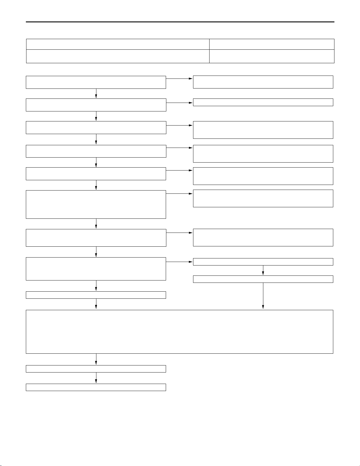
13D-56
INSPECTION PROCEDURE 22
MPI <4G63> ï Troubleshooting
Too high CO and HC concentration when idling
Abnormal air-fuel ratio is suspected. D Malfunction of the air-fuel ratio control system
YES
M.U.T.-II/III Self-Diag code
Are diagnosis codes displayed?
NO
Check the ignition timing.
(Refer to GROUP 11C ï On-vehicle Service.)
OK
M.U.T.-II/III Data list
21 Engine coolant temperature sensor. (Refer to P.13D-66.)
OK
M.U.T.-II/III Data list
13 Intake air temperature sensor (Refer to P.13D-66.)
OK
M.U.T.-II/III Data list
25 Barometric pressure sensor (Refer to P.13D-66.)
OK
M.U.T.-II/III Data list
59 Oxygen sensor (rear)
D Transmission: D range
D Driving with throttle widely open
OK: 600 ï 1,000 mV
OK
M.U.T.-II/III Data list
11 Oxygen sensor (front)
OK: 600 ï 1,000 mV when racing suddenly.
OK
M.U.T.-II/III Data list
11 Oxygen sensor (front)
OK: Repeat 0 ï 400 mV and 600 ï 1,000 mV alternately when
idling.
NG
Check the fuel pressure. (Refer to P.13D-92.)
OK
NG
NG
NG
NG
NG
NG
OK
Probable cause
D Deteriorated catalyst
Refer to P.13D-12, INSPECTION CHART FOR DIAGNOSIS
CODES.
Check that the crank angle sensor is installed properly.
Check the engine coolant temperature sensor system.
(Referto P.13D-20,INSPECTIONPROCEDUREFOR DIAGNOSIS
CODE 21.)
Check the intake air temperature sensor system.
(Referto P.13D-16,INSPECTIONPROCEDUREFOR DIAGNOSIS
CODE 13.)
Check the barometric pressure sensor system.
(Referto P.13D-26,INSPECTIONPROCEDUREFOR DIAGNOSIS
CODE 25.)
Check the oxygen sensor (rear) system.
(Referto P.13D-32,INSPECTIONPROCEDUREFOR DIAGNOSIS
CODE 59.)
Check the oxygen sensor (front) system.
(Referto P.13D-13,INSPECTIONPROCEDUREFOR DIAGNOSIS
CODE 11.)
Replace the oxygen sensor.
Check the trouble symptom.
NG
Check the following items.
D Check the injectors for operation sound.
D Check the injectors for fuel leakage.
D Check the ignition coil, spark plugs, spark plug cables.
D Check the compression pressure.
D Check the positive crankcase ventilation system.
D Check the purge control system.
D Check the EGR control system.
Check the trouble symptom.
NG
Replace the catalytic converter.
Page 62

INSPECTION PROCEDURE 23
MPI <4G63> ï Troubleshooting
13D-57
Low alternator output voltage (approx. 12.3 V)
The alternator may be defective, or malfunctions, which are listed in the right column,
may be suspected.
Measureat the alternatorconnectorside
B-26.
D Connect the connector.
(Test harness: MB991519)
D Voltage between 1 (black clip) and
earth
(Engine: Idling)
(Radiator fan: Not operating)
(Head lamp: OFF o ON)
(Stop lamp: OFF o ON)
(Rear defogger switch: OFF o ON)
OK: Voltage rises by 0.2 ï 3.5 V.
OK
Check the alternator. (Refer to GROUP
16 ï Charging System.)
NG
Measure at the alternator connector.
B-26
D Disconnect the connector, and
measure at the harness side.
D Disconnect the engine-A/T-ECU
connector.
D Continuity between 1 and earth
OK: No continuity
OK
Check the following connectors:
B-18, C-122
OK
Check the trouble symptom.
INSPECTION PROCEDURE 24
Idling speed is improper when A/C is operating
If the engine-A/T-ECU detects that the air conditioner is on, it activates the idle
speed control (ISC) servo to control idle-up operation.
The automatic compressor-ECU judges if the load caused by air conditioner
operation is high or low, and converts it to voltage signal (high or low voltage)
and inputs the signal to the engine-A/T-ECU.
Based on this voltage signal, the engine-A/T-ECU controls the idle-up speed (for
high or low load).
Probable cause
D Malfunction of the charging system
(Refer to GROUP 16 ï Charging System.)
D Short circuit in harness between alternator G terminal
and engine-A/T-ECU
D Malfunction of the engine-A/T-ECU
NG
NG
NG
Check the harness wire between the
alternatorandthe engine-A/T-ECUconnector, and repair if necessary.
Repair
Replace the engine-A/T-ECU.
Probable cause
D Malfunction of the A/C control system
D Improper connector contact, open circuit or
short-circuited harness wire
D Malfunction of the engine-A/T-ECU
Measure at the engine-A/T-ECU connector C-124.
D Connect the connector.
D Voltage between 61 and earth (Engine: at idle, outside air
temperature: 25_C or more)
OK: 0 ï 3 V [When A/C is MAX. COOL condition (when
the load by A/C is high)]
System voltage [When A/C is MAX. HOT condition
(when the load by A/C is low)]
NG
Check the A/C system. (Refer to GROUP 55 ï On-vehicle Service.)
OK
Check the following connector:
C-124
OK
Check the trouble symptom.
NG
Replace the engine-A/T-ECU.
NG
Repair
Page 63

13D-58
INSPECTION PROCEDURE 25
MPI <4G63> ï Troubleshooting
Fans (radiator fan, A/C condenser fan) are inoperative.
The engine-A/T-ECU sends a duty signal to the fan controller according to engine
coolant temperature, vehicle speed, or A/C switch.
The fan controller controls radiator fan and condenser fan speeds, based on this
signal. (The closer the terminal voltage comes to 5V,the higher the fan speed becomes.)
Measure at the engine-A/T-ECU connector C-122.
D Disconnect the connector, measure at the harness side.
D Voltage between terminal 18 and earth
(Ignition switch: ON)
OK: 4.8 ï 5.2 V (The fan runs at high speed.)
D Earth terminal 18.
(Ignition switch: ON)
OK: The fan stops.
OK
Check the following connector: C-122
OK
Check the trouble symptom.
NG
M.U.T.-II/III Data list
21 Engine coolant temperature sensor
OK: After the engine has been warmed up, the engine coolant
temperature during idling is identical to the M.U.T.-II/IIIreading.
OK
Check the thermostat.
OK
NG
NG
NG
NG
Check the harness wire between the engine-A/T-ECU and fan controller.
Check the radiator fan and condenser fan circuit. (Refer to GROUP
14 ï Troubleshooting.)
Repair
Check the engine coolant temperature sensor system. (Refer to
P.13D-20, INSPECTION PROCEDURE FOR DIAGNOSIS DODE
21.)
Replace
Probable cause
D Malfunction of the fan motor relay
D Malfunction of the fan motor
D Malfunction of the fan controller
D Open or short circuit, or poor connector contact
D Malfunction of the engine-A/T-ECU
OK
NG
Repair
Replace the engine-A/T-ECU.
Page 64

MPI <4G63> ï Troubleshooting
INSPECTION PROCEDURE 26
Check the engine-A/T-ECU power supply and earth circuit.
13D-59
Measure the engine-A/T-ECU connectors, C-124, C-126.
D Disconnect the connector and measure at the harness side
(1) Voltage between 98 and earth (Ignition switch: ON)
OK: System voltage
(2) Voltage between 49 and earth
OK: System voltage
(3) Voltage between 41, 47 and earth
OK: System voltage (when the terminal 49 is earthed)
(4) Continuity between 42, 48 and earth
OK: Continuity
(5) Voltage between 66 and earth
OK: System voltage
OK
Check the following
connectors:
C-124, C-126
OK
Check the trouble symptom.
NG
Replace the engine-A/T-ECU.
Check the harness wire between engine-A/T-ECU and battery,
and repair if necessary.
NG
Repair
(1) NG
(2), (3) NG
(4) NG
(5)
NG
Check the following
connectors: C-14,
C-209, Cï210
OK
Check the trouble symptom.
OK
Check the harness wire
betweenengine-A/T-ECU
and ignition switch connector.
OK
Check the ignition switch.
(Refer to GROUP 54 ï Ignition Switch and Immobilizer System.)
Check the following
connectors: A-13,
B-16X, C-12
OK
Check the trouble symptoms.
NG
Check the harness wire between engine-A/T-ECUand control relay
connector, and repair if necessary.
Check the harness wire between engine-A/T-ECU and earth, and
repair if necessary.
NG
NG
NG
Repair
Repair
Repair
INSPECTION PROCEDURE 27
Power supply system and ignition switch-IG system
When an ignition switch ON signal is input to the engine-A/T-ECU,the engine-A/T-ECU
turns the engine control relay ON. This causes battery voltage to be supplied to the
engine-A/T-ECU, injectors and air flow sensor.
Check the engine control relay. (Refer to P.13D-96.)
OK
Measure at the engine control relay connector B-16X.
D Disconnect the connector, and measure at the harness side.
D Voltage between 3, 4 and earth
OK: System voltage
OK
Check the engine-A/T-ECU power supply and earth circuit.
(Refer to P.13D-59, INSPECTION PROCEDURE 26.)
NG
NG
Probable cause
D Malfunction of the ignition switch
D Malfunction of the engine control relay
D Improper connector contact, open circuit or
short-circuited harness wire
D Disconnected engine-A/T-ECU earth wire
D Malfunction of the engine-A/T-ECU
Replace
Check the following
connector: A-13
OK
Check the trouble symptom.
NG
Checktheharness wire betweenbatteryand control relayconnector,
and repair if necessary.
NG
Repair
Page 65

13D-60
INSPECTION PROCEDURE 28
MPI <4G63> ï Troubleshooting
Fuel pump system
Engine-A/T-ECU turns fuel pump relay ON to supply drive voltage to fuel pump while
engine is cranked and rotated.
M.U.T.-II/III Actuator test
07 Fuel pump (Refer to P.13D-70.)
NG
Check fuel pump relay (1).
(Refer to P.13D-96.)
OK
Check fuel pump relay (2).
(Refer to P.13D-96.)
OK
Measure at connector C-222 of fuel
pump relay (1)
D Disconnect the connector to
measure at the harness side
(1) Voltage of terminal No. 1 ï earth
(Ignition switch: ON)
OK: System voltage
(2) Voltage of terminal No. 2 ï earth
OK: System voltage
(3) Continuity of terminal No. 4 ï earth
OK: Continuity
OK
NG
NG
(1) NG
(2) NG
Normal
Replace
Replace
Check the following connector:
C-210
OK
Check the trouble symptom.
Check the following connectors:
C-209, C-27
OK
Check and repair harness from fuel
pump relay (1) to battery.
Probable cause
D Malfunction of the fuel pump relay (1)
D Malfunction of the fuel pump relay (2)
D Malfunction of the fuel pump
D Improper connector contact, open circuit or
short-circuited harness wire
D Malfunction of the engine-A/T-ECU
NG
NG
NG
Repair
Check harness from fuel pump relay
(1) to ignition switch.
Repair
Check ignitionswitch. (RefertoGROUP
54A ï Ignition Switch.)
OK
NG
Repair
OK
Measure at connector C-220 of fuel
pump relay (2)
D Disconnect the connector to
measure at the harness side.
D Ignition switch: ON
(1) Voltage of terminal No.1 ï earth
OK: System voltage
(2) Voltage of terminal No.3 ï earth
OK: System voltage
OK
To the next page.
(3) NG
(1) NG
(2) NG
Check the following connector:
C-212
OK
Check and repair harness from fuel
pump relay (1) to earth.
Check the following connector:
C-210
OK
Check the trouble symptom.
Check the following connector:
C-222
OK
Check and repair harness from fuel
pump relay (1) to fuel pump relay (2).
NG
Repair
NG
NG
NG
Repair
Repair
Check harness from fuel pump relay
(2) to ignition switch.
OK
Check ignition switch. (Refer to GROUP
54A ï Ignition Switch.)
NG
Repair
Page 66

From the previous page.
OK
Measure at the C-122 engine-A/T-ECU
connector.
D Disconnect the connector to
measure at the harness side
D Voltage of terminal No. 21 ï earth
D Ignition switch: ON
OK: System voltage
OK
Measure at connector C-122 of engineA/T-ECU
D Disconnect the connector to
measure at the harness side
D Terminal No. 21 ï earth short circuit
D Ignition switch: ON
OK: Fuel pump is operated
(operating noise audible)
NG
Measure at connector D-16 of fuel pump
D Disconnect the connector to
measure at the harness side
(1) Voltage of terminal No. 5 ï earth
(Ignition switch: ON)
OK: System voltage
(2) Continuity of terminal No. 4 ï earth
OK: Continuity
OK
MPI <4G63> ï Troubleshooting
NG
OK
(1) NG
(2) NG
Check the following connectors:
C-14, C-212, Cï220
OK
Check the trouble symptom.
Check the following connector:
C-122
OK
Check the trouble symptom.
Check the following connectors:
D-18, C-215, C-220
OK
Check the trouble symptom.
Check the following connector:
D-16
OK
Check the trouble symptom.
NG
NG
NG
NG
NG
NG
NG
NG
13D-61
Repair
Check and repair harness from fuel
pump relay (2) to engine-A/T-ECU
Repair
Replace the engine-A/T-ECU.
Repair
Check and repair harness from fuel
pump relay (2) to fuel pump.
Repair
Check and repair harness from fuel
pump to earth.
Check the following connectors:
D-16, D-18, C-215, C-220
OK
Check the trouble symptom.
NG
Replace the fuel pump.
NG
Replace
Page 67

13D-62
INSPECTION PROCEDURE 29
MPI <4G63> ï Troubleshooting
Ignition switch-ST and inhibitor switch system
D The ignition switch-ST inputs a HIGH signal to the engine-A/T-ECU while the
engine is cranking.
The engine-A/T-ECU controls fuel injection, etc. during starting based on this input.
D The inhibitor switch inputs the condition of the select lever, i.e. whether it is in
P or N range or in some other range, to the engine-A/T-ECU.
The engine-A/T-ECU controls the idle speed control (ISC) servo based on this
input.
M.U.T.-II/III Data list
Check the 61 Inhibitor switch data list
of automatic transmission system.
(Refer to GROUP 23A ï Troubleshooting.)
OK
Check the inhibitor switch
D Continuity between the terminal 9
and terminal 10
(Refer to GROUP 23A ï
Troubleshooting.)
OK
Measure at the inhibitor switch connector B-20.
D Disconnect the connector, and
measure at the harness side.
D Voltage between 10 and earth
(Ignition switch: START)
OK: System voltage
OK
Measure at the engine-A/T-ECU connector C-124.
D Disconnect the connector, and
measure at the harness side.
D Voltage between 58 and earth
(Selector lever: P or N range)
(Ignition switch: START)
OK: System voltage
OK
NG
NG
NG
NG
Check the inhibitor switch system
(RefertoGROUP23A ï On-vehicle Service.)
Replace
Check the following connector:
C-14
OK
Check the trouble symptom.
NG
Check the harness wire between the
inhibitor switch and ignition switch.
NG
Repair
Check the following connector:
B-20
OK
Check the trouble symptom.
Probable cause
D Malfunction of the ignition switch
D Malfunction of the inhibitor switch
D Improper connector contact, open circuit or
short-circuited harness wire
D Malfunction of the engine-A/T-ECU.
NG
OK
NG
NG
Repair
Check the ignition switch (Refer to
GROUP 54 ï Ignition Switch and
Immobilizer system.)
Repair
Check the harness wire between the
inhibitor switch and engine-A/T-ECU,
and repair if necessary.
Check the following connector:
C-124
OK
Check the trouble symptom.
NG
Replace the engine-A/T-ECU.
NG
Replace
Page 68

INSPECTION PROCEDURE 30
MPI <4G63> ï Troubleshooting
13D-63
Power steering fluid pressure switch system
The presence or absence of power steering load is input to the engine-A/T-ECU.
The engine-A/T-ECU controls the idle speed control (ISC) servo based on this input.
Check the power steering fluid pressure switch.
(Refer to GROUP 37A ï On-vehicle Service.)
OK
Measure at the power steering fluid pressure switch connector
B-115.
D Disconnect the connector, and measure at the harness side.
D Voltage between 1 and earth (Ignition switch: ON)
OK: System voltage
OK
Check the following
connector: B-115
OK
Check the trouble symptom.
NG
Replace the engine-A/T-ECU.
NG
Repair
NG
NG
INSPECTION PROCEDURE 31
Probable cause
D Malfunction of the power steering fluid pressure switch
D Improper connector contact, open circuit or
short-circuited harness wire
D Malfunction of the engine-A/T-ECU
Replace
Check the following
connector: C-124
OK
Check the trouble symptom.
NG
Check harness wire between engine-A/T-ECU
and power steering fluid
pressure switch connector.
OK
Replace the engine-A/T-ECU.
NG
NG
Repair
Repair
A/C switch and A/C relay system
When an A/C ON signal is input to the engine-A/T-ECU, the engine-A/T-ECU carries
out control of the idle speed control (ISC) servo, and also operates the A/C compressor
magnetic clutch.
Check the A/C compressor relay.
(Refer to GROUP 55 ï On-vehicle Service.)
OK
Measure at the engine-A/T-ECU connectors C-122, C-126.
D Disconnect the connectors, and measure at the harness side.
D Voltage between 20 and earth, and 83 and earth
(Ignition switch: ON, A/C switch: ON)
OK: System voltage
D Short circuit between 20 and earth
OK: A/C compressor clutch turns on.
NG
NG
OK
Replace
Check the A/C system. (Refer to GROUP 55 ï On-vehicle Service.)
Check the following
connectors: C-122,
C-126
Check the trouble symptom.
Replace the engine-A/T-ECU.
Probable cause
D Malfunction of the A/C control system
D Malfunction of the A/C switch
D Improper connector contact, open circuit or
short-circuited harness wire
D Malfunction of the engine-A/T-ECU
NG
OK
NG
Replace
Page 69
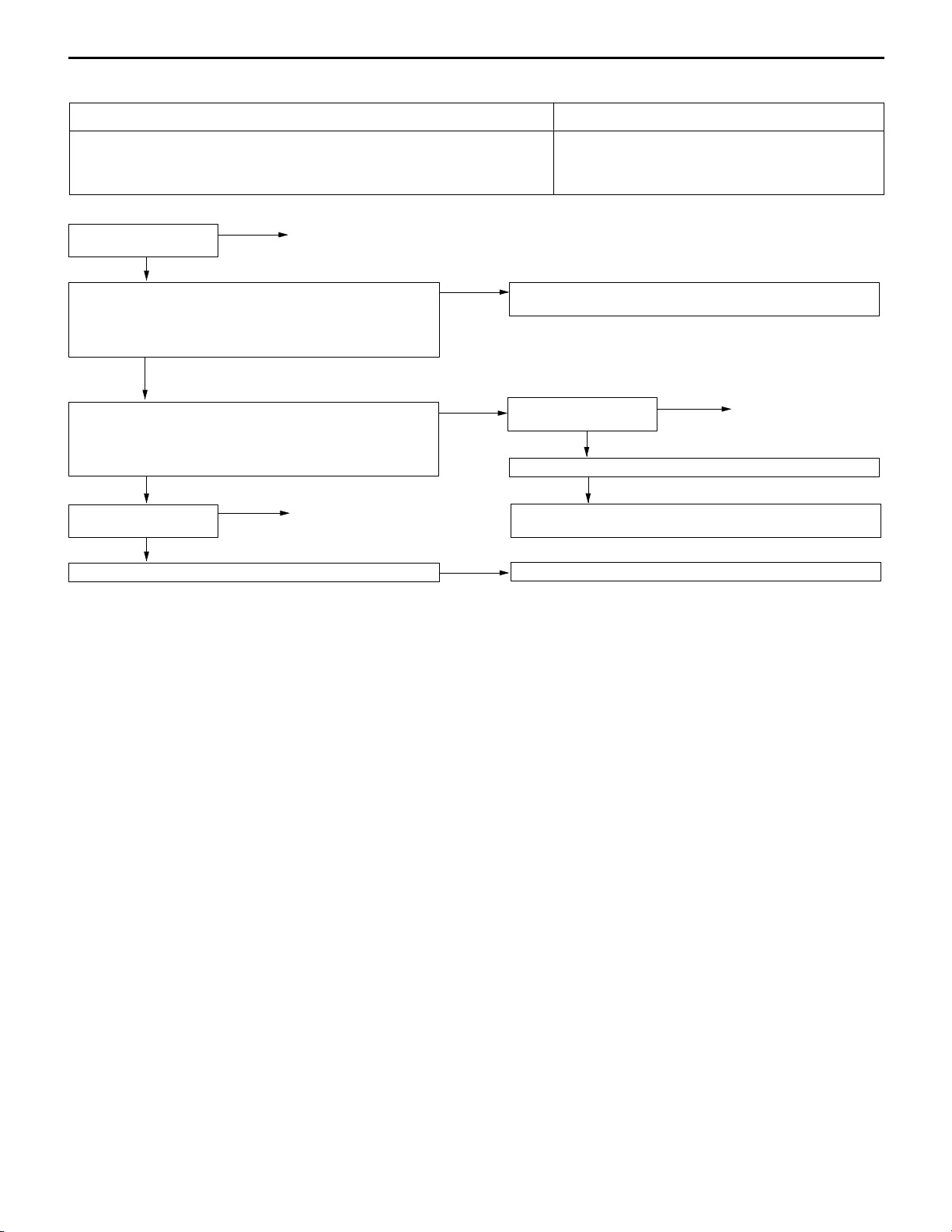
13D-64
INSPECTION PROCEDURE 32
MPI <4G63> ï Troubleshooting
Idle speed control (ISC) servo (Stepper motor) system
The engine-A/T-ECUcontrols the intake air volume during idling by opening andclosing
the servo valve located in the bypass air passage.
Check the ISC servo
(Refer to P.13D-102.)
OK
Measure at the ISC servo connector B-103.
D Disconnect the connector and measure at the harness side.
D Voltage between 2 and earth, and 5 and earth
(Ignition switch: ON)
OK: System voltage
OK
Measure at the engine-A/T-ECU connector C-122.
D Disconnect the connector, measure at the harness side.
D Voltage between each of 14, 15, 28, 29 and earth (Ignition
switch: ON)
OK: System voltage
OK
Check the following
connector: C-122
OK
Check the trouble symptom.
NG
NG
Replace
Repair
NG
NG
NG
Check the harness wire between control relay and ISC servo connector, and repair if necessary.
Check the following
connector: B-103
Check the trouble symptom.
Check harness wire between engine-A/T-ECU and ISC servo connector, and repair if necessary.
Replace the engine-A/T-ECU.
Probable cause
D Malfunction of the ISC servo
D Improper connector contact, open circuit or
short-circuited harness wire
D Malfunction of the engine-A/T-ECU
NG
OK
NG
Repair
Page 70

INSPECTION PROCEDURE 33
MPI <4G63> ï TroubleshootingMPI <4G63> ï Troubleshooting
13D-65
Purge control solenoid valve system
The purge control solenoid valve controls the purging of air from the canister located
inside the intake manifold.
Check the purge control solenoid valve. (Refer to GROUP 17 ï
Emission Control System.)
OK
Measure at the purge control solenoid valve connector B-105.
D Disconnect the connector and measure at the harness side.
D Voltage between 2 and earth (Ignition switch: ON)
OK: System voltage
OK
Measure at the engine-A/T-ECU connector C-122.
D Disconnect the connector and measure at the harness side.
D Voltage between 34 and earth (Ignition switch: ON)
OK: System voltage
OK
Check the following connector: C-122
OK
Check the trouble symptom.
NG
Repair
NG
NG
NG
NG
Replace
Check the harness wire between engine control relay and solenoid
valve connector, and repair if necessary.
Checkthefollowing connector:B-105
Check the trouble symptom.
Check the harness wire between engine-A/T-ECU and solenoid
valve connector, and repair if necessary.
Replace the engine-A/T-ECU.
Probable cause
D Malfunction of the solenoid valve
D Improper connector contact, open circuit or
short-circuited harness wire.
D Malfunction of the engine-A/T-ECU
NG
OK
NG
Repair
INSPECTION PROCEDURE 34
EGR control solenoid valve system
The EGR control solenoid valve is controlled by the negative pressure resulting from
EGR operation leaking to port “A” of the throttle body.
Check the EGR control solenoid valve. (Refer to GROUP 17 ï
Emission Control System.)
OK
Measure at the EGR control solenoid valve connector B-101.
D Disconnect the connector and measure at the harness side.
D Voltage between 1 and earth (Ignition switch: ON)
OK: System voltage
OK
Measure at the engine-A/T-ECU connector C-122.
D Disconnect the connector and measure at the harness side.
D Voltage between 6 and earth (Ignition switch: ON)
OK: System voltage
OK
NG
Check the following connector: C-122
OK
Check the trouble symptom.
NG
Replace the engine-A/T-ECU.
Repair
NG
NG
NG
Probable cause
D Malfunction of the solenoid valve
D Improper connector contact, open circuit or
short-circuited harness wire.
D Malfunction of the engine-A/T-ECU
Replace
Check the harness wire between engine control relay and solenoid
valve connector, and repair if necessary.
Check the following connector: B-101
OK
Check the trouble symptom.
NG
Check the harness wire between engine-A/T-ECU and solenoid
valve connector, and repair if necessary.
NG
Repair
Page 71

13D-66
theair/fuel
*1t
2,500
83–123
H
MPI <4G63> ï Troubleshooting
DATA LIST REFERENCE TABLE
Caution
When shifting the select lever to D range, the brakes should be applied so that the vehicle does
not move forward.
NOTE
1
: In a new vehicle [driven approximately 500 km or less], the air intake plenum pressure is sometimes
*
10% higher than the standard pressure.
2
. The injector drive time represents the time when the cranking speed is at 250 r/min or below when
*
the power supply voltage is 11 V.
3
. In a new vehicle [driven approximately 500 km or less], the injector drive time is sometimes 10
*
longer than the standard time.
4
. In a new vehicle [driven approximately 500 km or less], the step of the stepper motor is sometimes
*
30 steps greater than the standard value.
Item
No.
Inspection
item
11 Oxygen
sensor
(front)
12 Air flow
sensor
Inspection contents Normal condition Inspection
procedure
No.
Engine:After having
warmed up
Air/fuel mixture is
madeleaner whendecelerating, and is made
richer when racing.
Engine:After having
warmed up
The oxygen sensor
signal is used to check
mixture
ratio, and control
condition is also
checked by the engine-A/T-ECU.
D Engine coolant
emperature:
80 ï 95 _C
D Lamps and all
accessories: OFF
D Transmission:
P range
When at 4,000 r/min,
engine is suddenly
decelerated
When engine is
suddenly raced
Engine is idling 400 mV or less
2,500 r/min 400 mV or less
Engine is idling 18 – 44 Hz
r/min
Engine is raced Frequency
200 mV or less
600ï1,000 mV
(Changes)
600ï1,000 mV
(Changes)
600ï1,000 mV
z
increases in
response to
racing
Code No.1113D-13
ï ï
Reference
page
13 Intake air
temperature
sensor
Ignition switch: ON or
with engine running
When intake air
temperature is ï20_C
When intake air
temperature is 0_C
When intake air
temperature is 20_C
When intake air
temperature is 40_C
When intake air
temperature is 80_C
ï20_C
0_C
20_C
40_C
80_C
Code No.1313D-16
Page 72

MPI <4G63> ï Troubleshooting
iti
14
signal
No.
29
13D-67
Item
No.
item
14 Throttle
pos
sensor
16 Power
supply
voltage
18 Cranking
signal
(ignition
switch-ST)
21 Engine
coolant
temperature
sensor
on
Normal conditionInspection contentsInspection
Ignition switch: ON
Ignition switch: ON System voltage Procedure
Ignition switch: ON
Ignition switch: ON or
with engine running
Set to idle position 535ï735 mV
Gradually open Increases in
proportion to
throttle opening
angle
Open fully 4,500ï5,000 mV
Engine: Stopped OFF
Engine: Cranking ON
When engine
coolant temperature
is ï20_C
When engine
coolant temperature
is 0_C
ï20_C
0_C
Inspection
procedure
No.
Code No.
No. 27
Procedure
No. 29
Code No.2113D-20
Reference
page
13D-18
13D-59
13D-62
22 Crank angle
sensor
D Engine: Cranking
D Tachometer:
Connected
D Engine: Idling
D Idle position
switch: ON
When engine
coolant temperature
is 20_C
When engine
coolant temperature
is 40_C
When engine
coolant temperature
is 80_C
Compare the engine
speed readings on
the tachometer and
the MUT-II/III.
When engine
coolant temperature
is ï20_C
When engine
coolant temperature
is 0_C
When engine
coolant temperature
is 20_C
20_C
40_C
80_C
Accord
1,103 – 1,303
r/min
1,103 – 1,303
r/min
1,103 – 1,303
r/min
Code No.2213D-22
When engine
coolant temperature
is 40_C
When engine
coolant temperature
is 80_C
924 – 1,124
r/min
650 – 850 r/min
Page 73

13D-68
25
(when
A/C
switch
is
No.
31
h
No.29
y
ef
ficiency
temperature:
p
g
cooling
fan
and
all
(Thetimingl
MPI <4G63> ï Troubleshooting
Item
No.
item
25 Barometric
pressure
sensor
27 Power
steering fluid
pressure
switch
28 A/C switch Engine: Idling
29 Inhibitor
switc
37 Volumetric
efficienc
Ignition switch: ON
Engine: Idling
(when A/C switch is
ON, A/C compressor
should be operating.)
Ignition switch: ON
D Engine coolant
temperature:
85ï95_C
D Lamps, and all
accessories: OFF
D Transmission:
P range
Normal conditionInspection contentsInspection
At altitude of 0 m 101 kPa
At altitude of 600 m 95 kPa
At altitude of 1,200 m 88 kPa
At altitude of 1,800 m 81 kPa
Steering wheel
stationary
Steering wheel
turning
A/C switch: OFF OFF
A/C switch: ON ON
P or N PorN
D, 3, 2, L or R D, 3, 2, L or R
Engine is idling 20 ï 30 %
2,500 r/min 20 ï 30 %
When engine is
suddenly raced
OFF
ON
Increases
Inspection
procedure
No.
Code No.
Procedure
No. 30
Procedure
No. 31
Procedure
ï ï
Reference
page
13D-58
13D-63
13D-63
13D-62
41
Injectors *
Injectors*
44 Ignition coils
and power
transistors
2
3
Engine: Cranking
D Engine coolant
temperature:
85ï95_C
D Lamps, electric
coolin
accessories: OFF
D Transmission:
P range
D Engine: After
having warmed up
D Timing lamp is set.
set in order to
check actual
ignition timing.)
fan and all
ampis
When engine
coolant temperature
is 0_C (injection is
carried out for all
cylinders
simultaneously)
When engine
coolant temperature
is 20_C
When engine
coolant temperature
is 80_C
Engine is idling 2.2 – 3.4 ms
2,500 r/min 2.5 – 3.7 ms
When engine is
suddenly raced
Engine is idling 2 – 18_BTDC
2,500 r/min 20 – 40_BTDC
14.7 – 22.1 ms
26.2 – 39.4 ms
6.6 – 9.8 ms
Increases
ï ï
ï ï
ï ï
Page 74

MPI <4G63> ï Troubleshooting
motor
8595C
13D-69
Item
No.
item
45 ISC
(stepper)
motor
position *4
49 A/C relay Engine: After having
59 Oxygen
sensor
(rear)
D Engine coolant
temperature:
85ï95_C
D Lamps, electric
cooling fan and all
accessories: OFF
D Transmission:
P range
D Engine: Idling
D When A/C switch is
ON, A/C
compressor should
be operating
warmed up/Engine is
idling
Engine: After having
warmed up
Normal conditionInspection contentsInspection
A/C switch: OFF 2ï25 STEP
A/C switch:
OFF o ON
D A/C switch: OFF
D Select lever:
N range o D
range
A/C switch: OFF OFF (Compressor
A/C switch: ON ON (Compressor
Engine is raced 600 ï 1000 mV Code No.5913D-32
Increases by
10ï70 steps
Increases by
5ï50 steps
clutch is not
operating)
clutch is
operating)
Inspection
procedure
No.
ï ï
Procedure
No. 31
Reference
page
13D-63
Page 75

13D-70
idli
dif
f
t
(b
MPI <4G63> ï Troubleshooting
ACTUATOR TEST REFERENCE TABLE
Item
No.
Inspection
item
01 Injectors Cut fuel to No. 1
02 Cut fuel to No. 2
03 Cut fuel to No. 3
04 Cut fuel to No. 4
07 Fuel pump Fuel pump
Drive contents Inspection contents Normal
injector
injector
injector
injector
operates and
fuel is recirculated.
Engine:
After having warmed up/Engineis
(Cut the fuel supply to each
injector in turn and check
cylinders which don’t affect
idling.)
D Engine:
D Fuel
ng
Cranking
pump:
Forced
driving
Inspect
according
to
both the
above
conditions.
’
Pinch the
return hose
with fingers
to feel the
pulse of the
fuel being
recirculated.
Listen near
the fuel tank
for the
sound of fuel
pump
operation.
Inspection
condition
Idling condition becomes
eren
comes unstable).
Pulse is felt. Procedure
Sound of
operation is
heard.
procedure
No.
Code No.4113D-29
e-
No. 28
Reference
page
13D-60
08 Purge
control
solenoid valve
10 EGR
control
solenoid valve
17 Basic ignition
timing
21 Fan controller Drive the fan
Solenoid valve
turns from OFF
to ON.
Solenoid valve
turns from OFF
to ON.
Set the engineA/T-ECU to ignition timing adjustment mode
motors
Ignition switch: ON Sound of op-
eration can be
heard when
solenoid valve
is
driven.
Ignition switch: ON Sound of op-
eration can be
heard when
solenoid valve
is driven.
D Engine: Idling
D Timing light is set
D Ignition switch: ON
D A/C switch: ON
5 _BTDC ï ï
Fan motor
runs
Procedure
No. 33
Procedure
No. 34
Procedure
No. 25
13D-65
13D-65
13D-58
Page 76

MPI <4G63> ï Troubleshooting
13D-71
Needle-nosed wire probe
CHECK AT THE ENGINE-A/T-ECU TERMINALS
TERMINAL VOLTAGE CHECK CHART
1. Connect a needle-nosed wire probe (test harness:
MB991223) to a voltmeter probe.
2. Insert the needle-nosed wire probe into each of the
engine-A/T-ECU connector terminals from the wire side,
and measure the voltage while referring to the check
chart.
NOTE
(1) Make the voltage measurement with the
engine-A/T-ECU connectors connected.
(2) You may find it convenient to pull out the
engine-A/T-ECU to make it easier to reach the
connector terminals.
(3) The checks can be carried out off the order given
in the chart.
Caution
Short-circuiting the positive (+) probe between a
connector terminal and earth could damage the
vehicle wiring, the sensor, engine-A/T-ECU or all of
them. Be careful to prevent this!
3. If voltmeter shows any division from standard value, check
the corresponding sensor, actuator and related electrical
wiring, then repair or replace.
4. After repair or replacement, recheck with the voltmeter
to confirm that the repair has corrected the problem.
Page 77

13D-72
ily
d
(f
t)
heat
12
Ignition
coil
No.
2,
A/Cswitch
OFFoON
(A/C
l
MPI <4G63> ï TroubleshootingMPI <4G63> ï Troubleshooting
Engine-A/T-ECU Connector Terminal Arrangement
Terminal
No.
1 No. 1 injector While engine is idling after having warmed
9 No. 2 injector
24 No. 3 injector
2 No. 4 injector
3 Oxygen sensor
6 EGR control sole-
8 Alternator G termi-
11 Ignition coil ï No. 1,
Check item Check condition (Engine condition) Normal condition
up, suddenlydepressthe accelerator pedal. momentar
Engine: Idling after warming up 1 V or less
ron
noidvalve
nal
No. 4
er
Engine r/min: 5,000 r/min System voltage
Ignition switch: “ON” System voltage
While engine is idling, suddenly depress the
accelerator pedal
D Engine: Warm, idle (radiator fan: OFF)
D Headlamp: OFF o ON
D Stop lamp: OFF o ON
D Rear defogger switch: OFF o ON
Engine r/min: 3,000 r/min 0.3 ï 3.0 V
From 11 ï 14 V,
rops
slightly
From system voltage,
momentaly drops
Voltage increases by 0.2 ï 3.5 V
12 Ignition coil ï No. 2,
No. 3
14 Stepper motor coil
<A>
28 Stepper motor coil
<B>
15 Stepper motor coil
<C>
29 Stepper motor coil
<D>
18 Fan controller Radiator and condenser fan is not operating 0 ï 0.3 V
19 Air flow sensor
resetsigna
D Engine: Soon after the warmed up
engine is started.
D
is operating)
Radiator and condenser fan is operating 0.7 V or more
Engine: Idle speed 0 ï 1V
Engine r/min: 3,000 r/min 6 ï 9V
:
compressor
System voltage l 1 V or less
(Changes repeatedly)
Page 78

MPI <4G63> ï Troubleshooting
(
)
heat
41
P
Igniti
“ON”
Syst
h
13D-73
Terminal
No.
20 A/C relay D Engine: Idle speed
D A/C switch: OFF o ON (A/C compressor
is operating)
21 Fuel pump relay Ignition switch: “ON” System voltage
Engine: Idle speed 1 V or less
22 Engine warning
lamp
26 Oxygen sensor
rear
34 Purge control sole-
noidvalve
ower supply
47
43 Tachometer signal Engine r/min: 3,000 r/min 0.3 ï 3.0 V
er
Ignition switch: “LOCK” (OFF) o ”ON” 1 V or less o System voltage (After
Engine: Idling after warming up 1 V or less
Engine: Racing System voltage
Ignition switch: “ON” System voltage
Running at 3,500 r/min while engine is
warming up after having been started
“
on switch:
”
Normal conditionCheck condition (Engine condition)Check item
System voltage or momentarily 6 V
or more o 1 V or less
several seconds have elapsed)
1 V or less
em voltage
44 Engine coolant
temperature sensor
45 Crank angle sen-
sor
46 Sensor impressed
voltage
49 Engine control
relay
(power supply)
Ignition switch: “ON” When engine coolant
temperature is ï20_C
When engine coolant
temperature is 0_C
When engine coolant
temperature is 20_C
When engine coolant
temperature is 40_C
When engine coolant
temperature is 60_C
When engine coolant
temperature is 80_C
Engine: Cranking 0.4 ï 4.0 V
Engine: Idle speed 1.5 ï 2.5 V
Ignition switch: “ON” 4.9 ï 5.1 V
Ignition switch: “LOCK” (OFF) System voltage
Ignition switch: “ON” 1 V or less
3.9 ï 4.5 V
3.2 ï 3.8 V
2.3 ï 2.9 V
1.3 ï 1.9 V
0.7 ï 1.3 V
0.3 ï 0.9 V
52 Power steering
fluid pressure
switc
Engine: Idling after
warmed up
When steering wheel
is stationary
When steering wheel
is turned
System voltage
1 V or less
Page 79

13D-74
terminal
Headlamp:
OFF
ON
“ON”
MPI <4G63> ï Troubleshooting
Terminal
No.
54 Alternator FR
terminal
55 Barometric pres-
sure sensor
56 Camshaft position
sensor
58 Ignition switch ï ST Engine: Cranking 8Vormore
61 A/C load signal Refer to GROUP 55 ï Troubleshooting
D Engine: Warm, idle (radiator fan: OFF)
D Headlamp: OFF o ON
D Stop lamp: OFF o ON
D Rear defogger switch: OFF o ON
Ignition switch:
”
“
Engine: Cranking 0.4 ï 3.0 V
Engine: Idling 1.5 ï 3.0 V
(Inspection at Automatic compressor ï ECU terminal)
When altitude is 0 m 3.8 ï 4.2 V
When altitude is
600 m
When altitude is
1,200 m
When altitude is
1,800 m
Normal conditionCheck condition (Engine condition)Check item
Voltage decreases
3.5 ï 3.9 V
3.3 ï 3.7 V
3.0 ï 3.4 V
64 Intake air
temperature
sensor
65 Air flow sensor Engine: Idle speed 2.2 ï 3.2 V
66 Backup power
supply
71 Oxygen sensor
(front)
Ignition switch:
“ON”
Engine r/min: 2,500 r/min
Ignition switch: “LOCK” (OFF) System voltage
Engine: Running at 2,500 r/min after warmed
up (Check using a digital type voltmeter)
When intake air temperature is ï20_C
When intake air
temperature is 0_C
When intake air
temperature is 20_C
When intake air
temperature is 40_C
When intake air
temperature is 60_C
When intake air
temperature is 80_C
3.8 ï 4.4 V
3.2 ï 3.8 V
2.3 ï 2.9 V
1.5 ï 2.1 V
0.8 ï 1.4 V
0.4 ï 1.0 V
0 l 0.8 V (Changes repeatedly)
73 Oxygen sensor
(rear)
78 Throttle position
sensor
Engine: Idling after warmed up (Check using
a digital type voltmeter)
Ignition switch:
“ON”
Set throttle valve to
idle position
Fully open throttle
valve
0 l 0.6 V (Changes repeatedly)
0.535 ï 0.735 V
4.4 ï 5.3 V
Page 80

MPI <4G63> ï Troubleshooting
13D-75
Terminal
No.
83 A/C switch Engine: Idle speed Turn the A/C switch
OFF
Turn the A/C switch
ON (A/C compressor
is operating)
98 Ignition switch ï IG Ignition switch: “ON” System voltage
Normal conditionCheck condition (Engine condition)Check item
0.5 V or less
System voltage
Page 81

13D-76
MPI <4G63> ï Troubleshooting
CHECK CHART FOR RESISTANCE AND CONTINUITY
BETWEEN TERMINALS
1. Turn the ignition switch to “LOCK” (OFF) position.
2. Disconnect the engine-A/T-ECU connector.
3. Measure the resistance and check for continuity between
the terminals of the engine-A/T-ECU harness-side
connector while referring to the check chart.
NOTE
(1) When measuring resistance and checking continuity,
a harness for checking contact pin pressure should
be used instead of inserting a test probe.
(2) Checking need not be carried out in the order given
in the chart.
Caution
If the terminals that should be checked are mistaken,
or if connector terminals are not correctly shorted
to earth, damage may be caused to the vehicle wiring,
sensors, engine-A/T-ECU and/or ohmmeter.
Be careful to prevent this!
4. If the ohmmeter shows any deviation from the standard
value, check the corresponding sensor, actuator and
related electrical wiring, and then repair or replace.
5. After repair or replacement, recheck with the ohmmeter
to confirm that the repair or replacement has corrected
the problem.
Page 82

MPI <4G63> ï Troubleshooting
Engine-A/T-ECU Harness Side Connector Terminal Arrangement
13D-77
Terminal
No.
1 ï 41 No. 1 injector 10.5 ï 13.5 : (At 20_C)
9 ï 41 No. 2 injector
24 ï 41 No. 3 injector
2 ï 41 No. 4 injector
3 ï 41 Oxygen sensor (front) heater 4.5 ï 8.0 : (At 20_C)
6 ï 41 EGR control solenoid valve 30 ï 34 : (At 20_C)
14 ï 41 Stepper motor coil (A) 28 ï 33 : (At 20_C)
28 ï 41 Stepper motor coil (B)
15 ï 41 Stepper motor coil (C)
29 ï 41 Stepper motor coil (D)
26 ï 41 Oxygen sensor (rear) heater 11 ï 18 : (At 20_C)
34 ï 41 Purge control solenoid valve 29 ï 35 : (At 20_C)
42 ï Body
earth
Inspection item Normal condition (Check condition)
Engine-A/T-ECU earth Continuity (0 :)
48 ï Body
earth
44 ï 57 Engine coolant temperature sensor 14 ï 17 k:
(When coolant temperature is ï20_C)
5.1 ï 6.5 k:
(When coolant temperature is 0_C)
2.1 ï 2.7 k:
(When coolant temperature is 20_C)
0.9 ï 1.3 k:
(When coolant temperature is 40_C)
0.48 ï 0.68 k:
(When coolant temperature is 60_C)
0.26 ï 0.36 k:
(When coolant temperature is 80_C)
Page 83

13D-78
MPI <4G63> ï Troubleshooting
Terminal
No.
64 ï 16 Intake air temperature sensor 13 ï 17 k:
Normal condition (Check condition)Inspection item
(When intake air temperature is ï20_C)
5.3 ï 6.7 k:
(When intake air temperature is 0_C)
2.3 ï 3.0 k:
(When intake air temperature is 20_C)
1.0 ï 1.5 k:
(When intake air temperature is 40_C)
0.56 ï 0.76 k:
(When intake air temperature is 60_C)
0.30 ï 0.42 k:
(When intake air temperature is 80_C)
Page 84

MPI <4G63> ï Troubleshooting
13D-79
Oscilloscope
Special
patterns
pickup
Standard Wave Pattern
Observation conditions
Function Special patterns
Pattern height Low
Pattern selector Display
Engine r/min Idle
OSCILLOSCOPE
The output signals of the sensors and the conditions of the
actuation signals of the actuators can be inspected visually
by observing the waveforms on the oscilloscope.
AIR FLOW SENSOR
Measurement Method
1. Disconnect the air flow sensor connector, and connect
the special tool test harness (MB991709) in between (All
terminals should be connected).
2. Connect the oscilloscope special patterns pickup to air
flow sensor connector terminal No. 3.
Alternate Method (Test harness not available)
1. Connect the oscilloscope special patterns pickup to
engine-A/T-ECU terminal No. 65.
INSPECTION PROCEDURE USING AN
Page 85

13D-80
Standard wave pattern
(V)
10
MPI <4G63> ï Troubleshooting
T
T1 T2
The time (cycle time) T is reduced when
the amount of intake air increases.
Times T1 and T2 are equal.
0
Time
Observation conditions (from conditions above engine speed is increased by racing.)
(V)
10
T
Time
0
Wave Pattern Observation Points
Check that cycle time T becomes shorter and the frequency increases when the engine speed is increased.
Page 86

MPI <4G63> ï Troubleshooting
Examples of Abnormal Wave Patterns
D Example 1
Cause of problem
Sensor interface malfunction
Wave pattern characteristics
Rectangular wave pattern is output even when the engine
is not started.
D Example 2
Cause of problem
Damaged rectifier or vortex generation column
Wave pattern characteristics
Unstable wave pattern with nonïuniform frequency.
However, when an ignition leak occurs during acceleration,
the wave pattern will be distorted temporarily, even if
the air flow sensor is normal.
13D-81
Camshaftposition
sensor connector
Special patterns
pick-up
Crank angle
sensor connector
Oscilloscope
CAMSHAFT POSITION SENSOR AND CRANK ANGLE
SENSOR
Measurement Method
1. Disconnect the camshaft position sensor connector and
connect the special tool test harness (MB991709) in
between (All terminals should be connected).
2. Connect the oscilloscope special pattern pickup to
camshaft position sensor terminal No. 2.
3. Disconnect the crank angle sensor connector and connect
the special tool test harness (MD998478) in between.
4. Connect the oscilloscope special patterns pickup to crank
angle sensor terminal No. 2.
Alternate Method (Test harness not available)
1. Connect the oscilloscope special patterns pickup to
engine-A/T-ECU terminal No. 56 (When checking the
camshaft position sensor signal wave pattern).
2. Connect the oscilloscope special patterns pickup to
engine-A/T-ECU terminal No. 45 (When checking the
crank angle sensor signal wave pattern).
Page 87

13D-82
MPI <4G63> ï Troubleshooting
Standard Wave Pattern
Observation condition
Function Special patterns
Pattern height Low
Pattern selector Display
Engine r/min Idle
Standard wave pattern
Crank angle
sensor output
wave pattern
Camshaft position
sensor output
wave pattern
TDC: Top dead centre
(V)
0
0
2 engine revolutions
(1 camshaft revolution)
75_BTDC
5_BTDC
No. 1 TDC No. 3 TDC No. 4 TDC No. 2 TDC
T
The time (cycle time) T is
reduced when the engine
speed increases
Time
Wave Pattern Observation Points
Check that cycle time T becomes shorter when the engine speed increases.
Page 88

MPI <4G63> ï Troubleshooting
Examples of Abnormal Wave Patterns
D Example 1
Cause of problem
Sensor interface malfunction
Wave pattern characteristics
Rectangular wave pattern is output even when the engine
is not started.
D Example 2
Cause of problem
Loose timing belt
Abnormality in sensor disk
Wave pattern characteristics
Wave pattern is displaced to the left or right.
13D-83
Special
patterns
pickup
Oscilloscope
INJECTOR
Measurement Method
1. Disconnect the injector connector, and then connect the
special tool test harness set (MB991348) in between (All
terminals should be connected).
2. Connect the oscilloscope special patterns pickup to
terminal No. 2 of the injector connector.
Alternate Method (Test harness not available)
1. Connect the oscilloscope special patterns pickup to
engine-A/T-ECU terminal No. 1 (When checking the No.
1 cylinder).
2. Connect the oscilloscope special patterns pickup to
engine-A/T-ECU terminal No. 9 (When checking the No.
2 cylinder).
3. Connect the oscilloscope special patterns pickup to
engine-A/T-ECU terminal No. 24 (When checking the No.
3 cylinder).
4. Connect the oscilloscope special patterns pickup to
engine-A/T-ECU terminal No. 2 (When checking the No.
4 cylinder).
Page 89

13D-84
MPI <4G63> ï Troubleshooting
Standard Wave Pattern
Observation conditions
Function Special patterns
Pattern height Variable
Variable knob Adjust while viewing the wave pattern
Pattern selector Display
Engine speed Idle
Standard wave pattern
(V)
50
Point B
Injector drive time
Drive signal: ON Drive signal: OFF
0
Point A
Solenoid back
electromotive
force
(Approx. 7u10 V)
Wave Pattern Observation Points
Point A: Height of solenoid back electromotive force
Contrast with standard wave pattern Probable cause
Time
Power
voltage
Solenoid coil back electromotive force is low or doesn’t
appear at all.
Point B: Injector drive time
D The injector drive time will be synchronized with the
D When the engine is suddenly raced, the drive time will
When idling
When racing
Short in the injector solenoid
M.U.T.-II/III tester display.
be greatly extended at first, but the drive time will soon
match the engine speed.
Page 90

MPI <4G63> ï Troubleshooting
13D-85
Oscilloscope
Special
patterns
pickup
Standard wave pattern
Observation conditions
Function Special patterns
Pattern height High
Pattern selector Display
IDLE SPEED CONTROL (ISC) SERVO (STEPPER
MOTOR)
Measurement Method
1. Disconnect the ISC servo connector, and connect the
special tool test harness (MB991709) in between.
2. Connect the oscilloscope special patterns pickup to the
ISC servo side connector terminal No. 1, No. 3, No. 4
and No. 6 respectively.
Alternate Method (Test harness not available)
1. Connect the oscilloscope special patterns pickup to
engine-A/T-ECU terminal No. 14, connection terminal No.
15, connection terminal No. 28, and connection terminal
No. 29 respectively.
Engine condition When the engine coolant temperature is 20˚C or below, turn the ignition switch from ”LOCK”
(OFF) position to ”ON” (without starting the engine).
While the engine is idling, turn the A/C switch to ON.
Immediately after starting the warm engine.
Page 91

13D-86
Standard wave pattern
MPI <4G63> ï Troubleshooting
Stepper
motor
control
signal
wave
pattern
(V)
30
20
10
The wave pattern
appears for an
instant, but soon
disappears.
Point B
Coilreverse electromotive
force (Approx. 3 u 10 V)
Point A
Induced electromotive force
from the motor turning
Time
Wave pattern Observation Points
Check that the standard wave pattern appears when the stepper motor is operating.
Point A: Presence or absence of induced electromotive force from the motor turning (Refer to the abnormal
wave pattern).
Contrast with standard wave pattern Probable cause
Induced electromotive force does not appear or is extremely small. Motor is malfunctioning
Point B: Height of coil reverse electromotive force
Contrast with standard wave pattern Probable cause
Coil reverse electromotive force does not appear or is extremely small. Short in the coil
Page 92

Open
circuit
side
Normal
side
MPI <4G63> ï Troubleshooting
Examples of Abnormal Wave Pattern
D Example 1
Cause of problem
Motor is malfunctioning. (Motor is not operating.)
Wave pattern characteristics
Induced electromotive force from the motor turning does
not appear.
D Example 2
Cause of problem
Open circuit in the line between the stepper motor and
the engine-A/T-ECU.
Wave pattern characteristics
Current is not supplied to the motor coil on the open
circuit side (Voltage does not drop to 0 V).
Furthermore, the induced electromotive force waveform
at the normal side is slightly different from the normal
waveform.
13D-87
Page 93

13D-88
MPI <4G63> ï Troubleshooting
Oscilliscope
Measurement Method
1. Disconnect the ignition coil connector, and connect the
IGNITION COIL AND POWER TRANSISTOR
Special
patterns
pickup
special tool test harness set (MB991348) in between (All
terminals should be connected).
2. Connect the oscilloscope special patterns pickup to
terminal No. 3 of each ignition coil connector in turn.
Alternate Method (Test harness not available)
1. Connect the oscilloscope special patterns pickup to
engine-A/T-ECU terminal No. 11 (No. 1 ï No. 4),
connection terminal No. 12 (No. 2 ï No.3) respectively.
Standard Wave Pattern
Observation condition
Function Special patterns
Pattern height Low
Pattern selector Display
Engine r/min Approximately 1,200 r/min
Standard wave pattern
Crank angle
sensor output
wave pattern
Power transistor
control signal
wave pattern
(V)
6
4
2
0
4
2
0
T: Revolution time corresponding to a crank angle of 180_
T1: Time computed by the engine-A/T-ECU
T: Spark advance angle
75_BTDC
T1
T
T
5_BTDC
Compression top dead center
Ignition period
OFF ON
Dwell section
Page 94
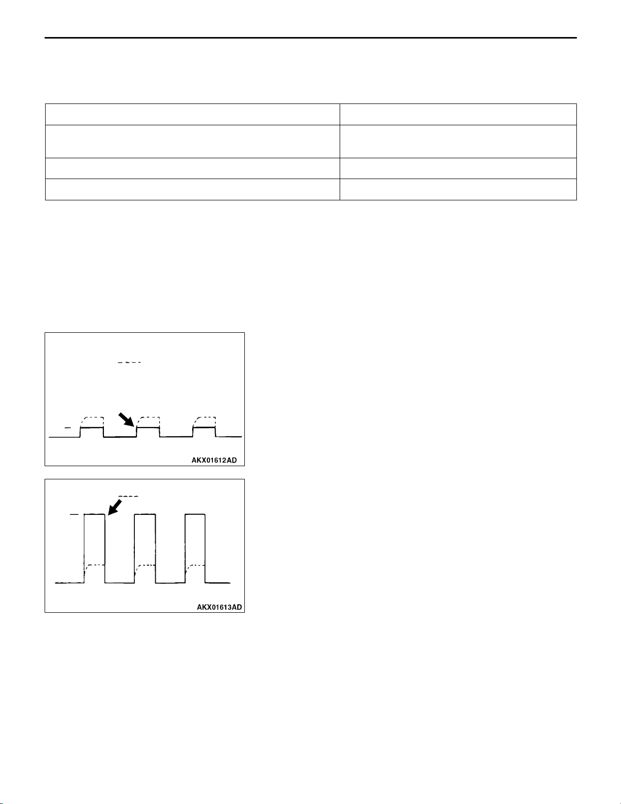
MPI <4G63> ï Troubleshooting
13D-89
Wave Pattern Observation Points
Point: Condition of wave pattern build-up section and maximum voltage (Refer to abnormal wave pattern
examples 1 and 2).
Condition of wave pattern build-up section and maximum voltage Probable cause
Rises from approximately 2 V to approximately 4.5 V at the
top-right
2 V rectangular wave Open-circuit in ignition primary circuit
Rectangular wave at power voltage Power transistor malfunction
Normal
Examples of Abnormal Wave Patterns
Normal wave pattern
D Example 1
Wave pattern during engine cranking
Cause of problem
Open-circuit in ignition primary circuit
2V
Wave pattern characteristics
Topïright part of the buildïup section cannot be seen,
and voltage value is approximately 2 V too low.
D Example 2
Normal wave pattern
V
B
Wave pattern during engine cranking
Cause of problem
Malfunction in power transistor
Wave pattern characteristics
Power voltage results when the power transistor is ON.
Page 95

13D-90
Areas on throttle valve to
apply molybdenum disulfide
MPI <4G63> ï On-vehicle Service
ON-VEHICLE SERVICE
THROTTLE BODY (THROTTLE VALVE AREA)
CLEANING
1. Remove the air intake hose from the throttle body.
2. Spray cleaning fluid on a clean cloth.
Caution
D Do not spray the cleaning fluid directly to the
15 mm
15 mm
3. Wipe off the dirt around the throttle valve with the cloth
4. Attach the air intake hose.
5. Adjust the basic idle speed (Refer to P.13D-91.)
throttle valve.
D Make sure the cleaning fluid does not enter the
motor from the bypass line. Also make sure it
does not enter the sensor through the shaft.
D Be careful not to rub off the molybden applied
around the throttle valve shaft.
sprayed with cleaning fluid.
Throttle position
sensor
Equipment side connector
Throttle position
sensor
MB991536
THROTTLE POSITION SENSOR ADJUSTMENT
1. Connect the M.U.T.-II/III to the diagnosis connector.
When not using the M.U.T.-II/III, proceed as follows.
(1) Disconnect the throttle position sensor connector and
connect the special tool test harness (MB991536)
between the disconnected connector taking care not
to confuse the terminal to be connected.
(2) Connect digital voltmeter between the terminal No.
2 (special tool’s yellow clip on the sensor output)
and the terminal No. 4 (special tool’s red clip on the
sensor earth) of the throttle position sensor connector.
2. Turn the ignition switch to ”ON” position (but do not start
the engine).
3. Check the output voltage of the throttle position sensor.
Standard value: 535 ï 735 mV
Page 96

MPI <4G63> ï On-vehicle Service
4. If not within the standard value, loosen the throttle position
sensor mounting bolts. Then rotate the sensor body to
adjust.
5. Turn the ignition switch to ”LOCK” (OFF) position.
6. Remove the M.U.T.-II/III. If the M.U.T.-II/III is not used,
remove the special tool, and then connect the throttle
position sensor connector.
7. If a diagnosis code is displayed, erase the diagnosis code
by using the M.U.T.-II/III or disconnect the negative battery
cable from the battery terminal and then leave it for at
least 10 seconds. After that, reconnect the battery cable,
and then let the engine run at idle for approximately 10
minutes.
13D-91
BASIC IDLE SPEED ADJUSTMENT
Caution
D The standard idling speed has been adjusted by the
speed adjusting screw (SAS) by the manufacturer,
and there should usually be no need for readjustment.
D If the adjustment has been changed by mistake, the
idle speed may become too high or the idle speed
may drop too low when loads from components such
as the A/C are placed on the engine. If this occurs,
adjust by the following procedure.
D The adjustment, if made, should be made after first
confirming that the spark plugs, the injectors, the
idle speed control servo, the compression pressure,
etc., are all normal.
1. Before inspection and adjustment, set the vehicle to the
pre-inspection condition.
2. Connect the M.U.T.-II/III to the diagnosis connector
(16-pin).
NOTE
When the M.U.T.-II/III is connected, the diagnosis control
terminal should be earthed.
3. Start the engine and run at idle.
4. Select the item No. 30 of the M.U.T.-II/III actuator test.
NOTE
This holds the ISC servo at the basic step to adjust the
basic idle speed.
5. Check the idle speed.
Standard value: 750 r 50 r/min
Page 97

13D-92
MPI <4G63> ï On-vehicle Service
NOTE
(1) The engine speed may be 20 to 100 r/min lower
than indicated above for a new vehicle [driven
approximately 500 km or less], but no adjustment
is necessary.
(2) If the engine stalls or the engine speed is low even
though the vehicle has been driven approximately
500 km or more, it is probable that deposits are
adhered to the throttle valve, so clean it (Refer to
P.13D-90.)
6. If not within the standard value range, turn the speed
adjusting screw (SAS) to make the necessary adjustment.
NOTE
If the idling speed is higher than the standard value range
even when the SAS is fully closed, check whether or
not there is any indication that the fixed SAS has been
moved. If there is an indication that it has been moved,
adjust the fixed SAS.
7. Press the M.U.T.-II/III clear key, and release the ISC
servo from the actuator test mode.
NOTE
Unless the ISC servo is released, the actuator test mode
will continue 27 minutes.
8. Turn the ignition switch to ”LOCK” (OFF) position.
9. Disconnect the M.U.T.-II/III.
10. Start the engine again and let it run at idle speed for
about 10 minutes; check that the idling condition is normal.
Delivery
pipe
MB991637
Gasket
MD998709
MD998742
High-pressure
fuel hose
FUEL PRESSURE TEST
1. Release residual pressure from the fuel pipe line to prevent
fuel gush out.
Caution
Cover the hose connection with rags to prevent splash
of fuel that could be caused by some residual pressure
in the fuel pipe line.
2. Disconnect the high-pressure fuel hose at the delivery
pipe side.
3. Assemble the fuel pressure measurement tools as follows.
<When using the fuel pressure gauge set (special tool)>
(1) Remove the union joint and bolt from the special
tool adaptor hose (MD998709) and attach the special
tool hose adaptor (MD998742) to the adaptor hose.
(2) Via a gasket, install the special tool fuel pressure
gauge set (MB991637 or MB991981) into the special
tool that has already assembled as described in (a)
above.
Page 98

Delivery
pipe
MB991981
Gasket
MD998709
MD998742
High-pressure
fuel hose
MPI <4G63> ï On-vehicle Service
<When using the fuel pressure gauge>
(1) Remove the union joint and bolt from special tool
adaptor hose (MD998709) and attach the special tool
hose adaptor (MD998742) to the adaptor hose.
(2) Via a suitable O-ring or gasket, install the fuel pressure
gauge to the special tool that has already assembled
as described in (a) above.
13D-93
Delivery
pipe
Vacuum hose
Fuel pressure
gauge set
O-ring or gasket
MD998709
MD998742
High-pressure
fuel hose
4. Install the assembled fuel pressure measurement tools
between the fuel rail and high-pressure fuel hose.
Caution
To prevent damage to the M.U.T.-II/III, always turn
the ignition switch to the ”LOCK” (OFF) position before
connecting or disconnecting the M.U.T.-II/III
5. Connect the M.U.T.-II/III to the diagnosis connector.
6. Turn the ignition switch to ”ON” position (But do not start
the engine)
7. Select ”Item No. 07” from the M.U.T.- II/III actuator test
to drive the fuel pump. Check that there are no fuel leaks
from any parts.
8. Finish the actuator test or turn the ignition switch to ”LOCK”
(OFF) position.
9. Start the engine and run at idle.
10. Fuel pressure measurement while the engine is running
at idle.
Standard value: Approximately 265 kPa at kerb idle
11. Disconnect the vacuum hose from the fuel pressure
regulator and measure fuel pressure with the hose end
closed by a finger.
Standard value: 324 ï 343 kPa at kerb idle
12. Check to see that fuel pressure at idle does not drop
even after the engine has been raced several times.
13. Racing the engine repeatedly, hold the fuel return hose
lightly with fingers to feel that fuel pressure is present
in the return hose.
Page 99

13D-94
Fuel
d
MPI <4G63> ï On-vehicle Service
NOTE
If the fuel flow rate is low, there will be no fuel pressure
in the return hose.
14. If any of fuel pressure measured in steps 10 to 13 is out of
specification, troubleshoot and repair according to the
table below.
Symptom Probable cause Remedy
D Fuel pressure too low
D
D No fuel pressure in fuel return
Fuel pressure too high Binding valve in fuel pressure
Same fuel pressure when vacuum
hose is connected and when disconnected
pressuredrops after racing
hose
Clogged fuel filter Replace fuel filter
Fuel leaking to return side due to poor
fuel regulator valve seating or settled
spring
Low fuel pump delivery pressure Replace fuel pump
regulator
Clogged fuel return hose or pipe Clean or replace hose or pipe
Damaged vacuum hose or Clogged
nipple
Replace fuel pressure regulator
Replace fuel pressure regulator
Replace vacuum hose or clean nipple
15. Stop the engine and check change of fuel pressure gauge
reading. Normal if the reading does not drop within 2
minutes. If it does, observe the rate of drop and
troubleshoot and repair according to the table below.
Symptom Probable cause Remedy
Fuel pressure drops gradually after
engineisstoppe
Leaky injector Replace injector
Leaky fuel regulator valve seat Replace fuel pressure regulator
Fuel pressure drops sharply
immediately after engine is stopped
Check valve in fuel pump is held open Replace fuel pump
16. Release residual pressure from the fuel pipe line.
Caution
Cover the hose connection with rags to prevent splash
of fuel that could be caused by some residual pressure
in the fuel pipe line.
17. Remove the fuel pressure gauge and special tool from
the delivery pipe.
18. Replace the O-ring at the end of the fuel high pressure
hose with a new one. Furthermore, apply engine oil to
the new O-ring before replacement.
19. Fit the fuel high pressure hose over the delivery pipe
and tighten the bolt to specified toque.
Tightening torque: 5.0 r 1.0 N·m
20. Check for any fuel leaks by following the procedure in
step 7.
21. Disconnect the M.U.T.-II/III.
Page 100

MPI <4G63> ï On-vehicle Service
b
)
13D-95
COMPONENT LOCATION
Name Symbol Name Symbol
Air flow sensor
(with intake air temperature sensor and
arometric pressure sensor
A/C compressor relay H Fuel pump relay (1) and (2) R
A/C switch U Idle speed control servo E
Camshaft position sensor O Ignition coil L
Crank angle sensor B Injector C
Detonation sensor J Oxygen sensor (front) K
Diagnosis connector T Oxygen sensor (rear) Q
EGR control solenoid valve I Power steering fluid pressure switch A
Engine control relay H Purge control solenoid valve I
Engine coolant temperature sensor N Throttle position sensor D
Engine-A/T-ECU V Vehicle speed sensor F
A B
D E F G H
C
G
Engine warming lamp
(check engine lamp)
Fan controller M
S
R S T U V
I J K L M N O P
Q
 Loading...