

Page 1
GROUP INDEX
LANCER /
LANCER WAGON
WORKSHOP MANUAL
FOREWORD
This Workshop manual contains procedures for
service mechanics, including removal, disassembly,
inspection, adjustment, reassembly and installation.
Use the following manuals in combination with this
manual as required.
General . . . . . . . . . . . . . . . . . . . . . . . .
Engine. . . . . . . . . . . . . . . . . . . . . . . . .
Engine Lubrication . . . . . . . . . . . . . .
Fuel . . . . . . . . . . . . . . . . . . . . . . . . . . .
Engine Cooling . . . . . . . . . . . . . . . . .
Intake and Exhaust . . . . . . . . . . . . . .
Engine Electrical . . . . . . . . . . . . . . . .
Engine and Emission Control . . . . .
Clutch . . . . . . . . . . . . . . . . . . . . . . . . .
Manual Transmission . . . . . . . . . . . .
Automatic Transmission. . . . . . . . . .
Front Axle. . . . . . . . . . . . . . . . . . . . . .
00
11
12
13
14
15
16
17
21
22
23
26
TECHNICAL INFORMATION MANUAL
PYME0302
PYME0302-A
WORKSHOP MANUAL
CHASSIS GROUP PWME0302
BODY REPAIR MANUAL
PBME0302
PBME0302-A
PARTS CATALOGUE
B606K005A_
All information, illustrations and product descriptions
contained in this manual are current as at the time of
publication. We, however, reserve the right to make
changes at any time without prior notice or obligation.
Rear Axle . . . . . . . . . . . . . . . . . . . . . .
Wheel and Tyre . . . . . . . . . . . . . . . . .
Power Plant Mount . . . . . . . . . . . . . .
Front Suspension . . . . . . . . . . . . . . .
Rear Suspension . . . . . . . . . . . . . . . .
Service Brakes. . . . . . . . . . . . . . . . . .
Parking Brakes . . . . . . . . . . . . . . . . .
Power Steering . . . . . . . . . . . . . . . . .
Body . . . . . . . . . . . . . . . . . . . . . . . . . .
Exterior . . . . . . . . . . . . . . . . . . . . . . . .
Interior and Supplemental
. . . . . . . . . .
Restraint System (SRS)
Chassis Electrical . . . . . . . . . . . . . . .
Heater, Air Conditioner and
. . . . . . .
Ventilation
Component Locations. . . . . . . . . . . .
27
31
32
33
34
35
36
37
42
51
52
54
55
70
Mitsubishi Motors Corporation May 2004
Configration Diagrams . . . . . . . . . . .
Circuit Diagrams . . . . . . . . . . . . . . . .
80
90
Page 2

WARNINGS REGARDING SERVICING OF SUPPLEMENTAL
RESTRAINT SYSTEM (SRS) EQUIPPED VEHICLES
(1) Improper service or maintenance of any component of the SRS or any SRS-related component,
can lead to personal injury or death to service personnel (from inadvertent firing of the air bag)
or to the driver and passenger (from rendering the SRS inoperative).
(2) The SRS components and seat belt with pretensioner should not be subjected to heat, so
remove the SRS-ECU, driverís and front passengerís air bag modules, clock spring, side air bag
modules, and seat belt -pre-tensioner before drying or baking the vehicle after painting.
ï SRS-ECU, air bag module and clock spring 93°C or more
ï Seat belt with pre-tensioner: 90°C or more
(3) Service or maintenance of any SRS component or SRS-related component must be performed
only at an authorized MITSUBISHI dealer.
(4) MITSUBISHI dealer personnel must thoroughly review this Manual, and especially its GROUP
52B - Supplemental Restraint System (SRS), before beginning any service or maintenance of
any component of the SRS or any SRS-related component.
NOTE
Section titles with asterisks (*) in the table of contents in each group indicate operations requiring warnings.
Page 3

GROUP 17
ENGINE AND
EMISSION
CONTROL
CONTENTS
17-1
ENGINE CONTROL. . . . . . . . . .
GENERAL INFORMATION . . . . . . 17-2
SERVICE SPECIFICATIONS. . . . . 17-2
ON-VEHICLE SERVICE. . . . . . . . . 17-2
ACCEL CABLE CHECK AND
ADJUSTMENT. . . . . . . . . . . . . . . . . . . . 17-2
ACCELERATOR CABLE AND
PEDAL . . . . . . . . . . . . . . . . . . . . . .
REMOVAL AND INSTALLATION . . . . . 17-3
17-2
17-3
EMISSION CONTROL MPI . . . . 17-5
GENERAL INFORMATION . . . . . .
EMISSION CONTROL DEVICE
REFERENCE TABLE . . . . . . . . . .
SERVICE SPECIFICATION(S) . . . 17-5
VACUUM HOSE. . . . . . . . . . . . . . . 17-6
VACUUM HOSE PIPING DIAGRAM . . . 17-6
VACUUM CIRCUIT DIAGRAM . . . . . . . 17-7
VACUUM HOSE CHECK. . . . . . . . . . . . 17-8
VACUUM HOSE INSTALLATION . . . . . 17-8
CRANKCASE EMISSION CONTROL
SYSTEM. . . . . . . . . . . . . . . . . . . . .
GENERAL INFORMATION (CRANKCASE
EMISSION CONTROL SYSTEM) . . . . . 17-8
17-5
17-5
17-8
COMPONENT LOCATION (CRANKCASE
EMISSION CONTROL SYSTEM) . . . . . 17-9
POSITIVE CRANKCASE VENTILATION
SYSTEM CHECK . . . . . . . . . . . . . . . . . . 17-9
POSITIVE CRANKCASE VENTILATION
(PCV) VALVE CHECK . . . . . . . . . . . . . . 17-9
EVAPORATIVE EMISSION CONTROL
SYSTEM . . . . . . . . . . . . . . . . . . . . . 17-9
GENERAL INFORMATION (EVAPORATIVE
EMISSION CONTROL SYSTEM) . . . . . 17-9
COMPONENT LOCATION (EVAPORATIVE
EMISSION CONTROL SYSTEM) . . . . . 17-10
PURGE CONTROL SYSTEM CHECK. . 17-10
PURGE PORT VACUUM CHECK . . . . . 17-11
PURGE CONTROL SOLENOID VALVE
CHECK . . . . . . . . . . . . . . . . . . . . . . . . . . 17-11
FUEL VAPOUR CANISTER REMOVAL
AND INSTALLATION . . . . . . . . . . . . . . . 17-12
EXHAUST GAS RECIRCULATION
(EGR) SYSTEM . . . . . . . . . . . . . . .
GENERAL INFORMATION
(EGR SYSTEM) . . . . . . . . . . . . . . . . . . . 17-13
COMPONENT LOCATION
(EGR SYSTEM) . . . . . . . . . . . . . . . . . . . 17-14
EGR SYSTEM CHECK . . . . . . . . . . . . . 17-15
EGR VALVE CHECK . . . . . . . . . . . . . . . 17-15
EGR PORT VACUUM CHECK <4G1>. . 17-16
EGR CONTROL SOLENOID VALVE
CHECK <4G1> . . . . . . . . . . . . . . . . . . . . 17-16
EGR CONTROL SOLENOID VALVE
CHECK <4G6> . . . . . . . . . . . . . . . . . . . . 17-17
EXHAUST GAS RECIRCULATION (EGR)
VALVE REMOVAL AND
INSTALLATION . . . . . . . . . . . . . . . . . . . 17-18
CATALYTIC CONVERTER . . . . . . 17-18
REMOVAL AND INSTALLATION . . . . . . 17-18
17-13
Page 4
17-2
ENGINE AND EMISSION CONTROL
ENGINE CONTROL
ENGINE CONTROL
GENERAL INFORMATION
M1171000100277
A cable-type accelerator mechanical
suspended-type pedal has been adopted.
SERVICE SPECIFICATIONS
M1171000300088
Item Standard value
Accel cable play mm 1.0 − 2.0
Engine idle speed r/min 4G1 750 ± 50
4G6 750 ± 100
ON-VEHICLE SERVICE
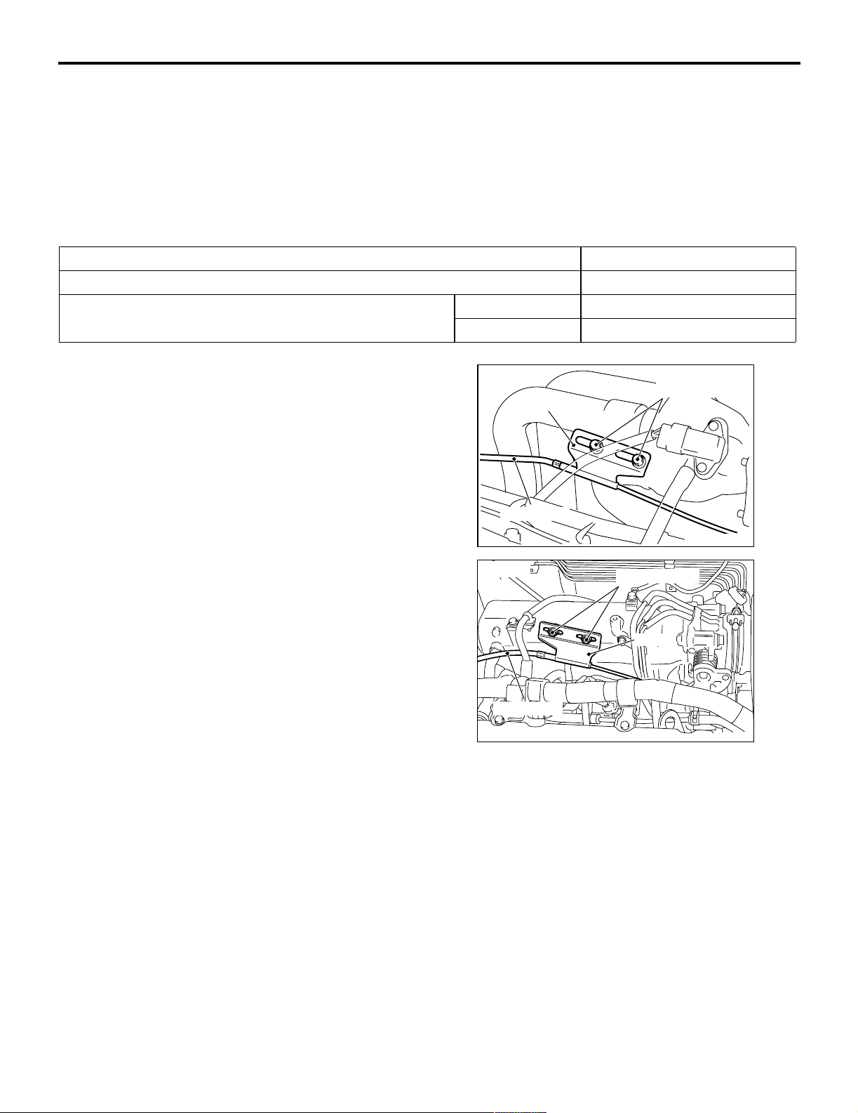
ACCEL CABLE CHECK AND
<4G1>
Adjusting bolts
Plate
ADJUSTMENT
M1171000900314
1. Turn A/C and lights OFF. Inspect and adjust at no
load.
2. Warm engine until stabilized at idle.
3. Confirm idle speed is at standard value.
Standard value:
750 ± 50 r/min <4G1>
750 ± 100 r/min <4G6>
Accel cable
<4G6>
Adjusting bolts
AC207966
AC
4. Stop engine. [ignition switch: LOCK (OFF)
position].
5. Confirm there are no sharp bends in the
accelerator cable.
6. Check the inner cable for correct slack.
Standard value: 1.0 − 2.0 mm
7. If there is too much slack or no slack, adjust play
by the following procedures.
Plate
Accel cable
AC301055
AC
(1) Loosen the adjusting bolts to release the
cable.
(2) Move the plate until the inner cable play is at
the standard value, and then tighten the
adjusting bolts.
(3) After adjusting, check that the throttle lever is
touching the stopper.
Page 5

ENGINE AND EMISSION CONTROL
ENGINE CONTROL
ACCELERATOR CABLE AND PEDAL
17-3
REMOVAL AND INSTALLATION
Post-installation Operation
Adjusting the Accelerator Cable (Refer to P.17-2).
<L.H. drive vehicles>
3
M1171001200341
2
5.0 ± 1.0 N·m
12 ± 2 N·m
10
1
7
9
7
N
5
4
<R.H. drive vehicles>
5.0 ± 1.0 N·m
2
Accelerator cable assembly
removal steps
1. Inner cable connection (Accelerator
pedal side)
2. Inner cable connection (Throttle body
side)
3. Accelerator cable assembly
8
13
N
12
6
Y1060AU
11
3
1
12 ± 2 N·m
9
7
13
11
12
6
N
Y1059AU
AC304070
AB
10
N
5
4
7
8
Accelerator pedal assembly
removal steps
1. Inner cable connection (Accelerator
pedal side)
4. Accelerator pedal assembly
5. Accelerator control equip nut
6. Accelerator pedal arm and
accelerator pedal pad assembly
Page 6
17-4
ENGINE AND EMISSION CONTROL
ENGINE CONTROL
Accelerator pedal assembly
removal steps (Continued)
7. Accelerator control equip bushing
8. Accelerator pedal arm return spring
9. Accelerator pedal arm stopper
INSTALLATION SERVICE POINT
>>A<< ACCEL PEDAL PAD
INSTALLATION
CAUTION
To p reve nt damag es to the ac c eler ator pe dal pad,
warm the thumb area of the accelerator pedal
pad with a dryer, etc. prior to assembling it.
NOTE: If it is difficult to assemble, apply soapy water
to the thumb area to enhance the assembling
process.
>>A<<
Accelerator pedal assembly
removal steps (Continued)
10. Accelerator pedal arm bracket
11. Ac c e l erator p edal a rm
12. Accelerator pedal pad
13. Accelerator pedal arm stopper
Page 7
ENGINE AND EMISSION CONTROL
EMISSION CONTROL <MPI>
EMISSION CONTROL <MPI>
17-5
GENERAL INFORMATION
M1173000100370
The emission control system consists of the following
subsystems:
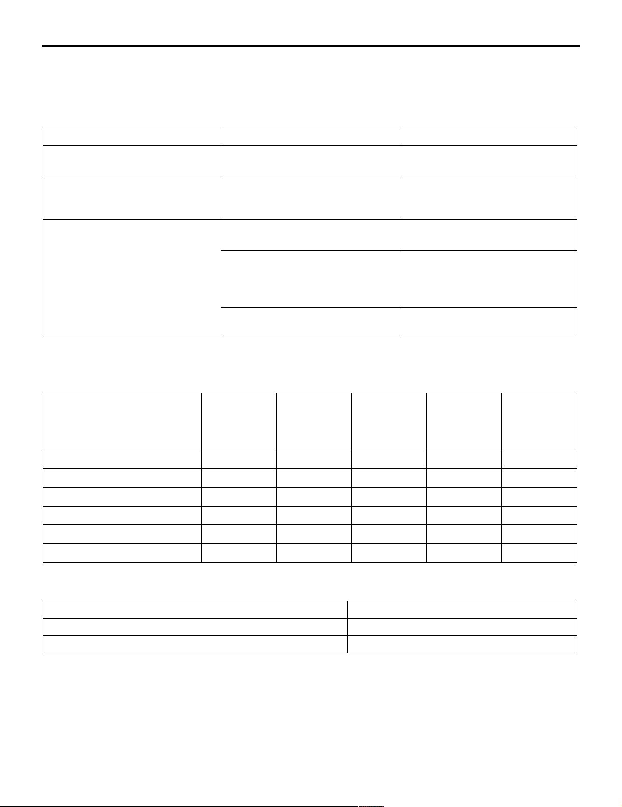
Items Name Specification
Crankcase emission control
system
Evaporative emission control
system
Exhaust emission control system Air-fuel ratio control device - MPI
Positive crankcase ventilation
(PCV) valve
Canister
Purge control solenoid valve
system
Exhaust gas recirculation system
• EGR valve
• EGR control solenoid valve
Catalytic converter Monolith type
• Crankcase emission control system
• Evaporative emission control system
• Exhaust emission control system
Varia b le flo w t yp e
(Purpose: HC reduction)
Equipped
Duty cycle type solenoid valve
(Purpose: HC reduction)
Oxygen sensor feedback type
(Purpose: CO, HC, NOx reduction)
Equipped
Single type
Duty cycle type solenoid valve
(Purpose: NOx reduction)
(Purpose: CO, HC, NOx reduction)
EMISSION CONTROL DEVICE
REFERENCE TABLE
M1173006600135
Related parts Crankcase
emission
control
system
Evaporative
emission
control
system
Air/fuel ratio
control
system
Catalytic
converter
Exhaust gas
recirculation
system
PCV valve
Purge control solenoid valve
MPI system component
Catalytic converter
EGR valve
EGR control solenoid valve
×
×
××
SERVICE SPECIFICATION(S)
M1173000300288
Items Standard value
Purge control solenoid valve coil resistance (at 20°C) Ω 30 − 34
EGR control solenoid valve coil resistance (at 20°C) Ω 29 − 35
×
×
×
Page 8
17-6
VACUUM HOSE
ENGINE AND EMISSION CONTROL
EMISSION CONTROL <MPI>
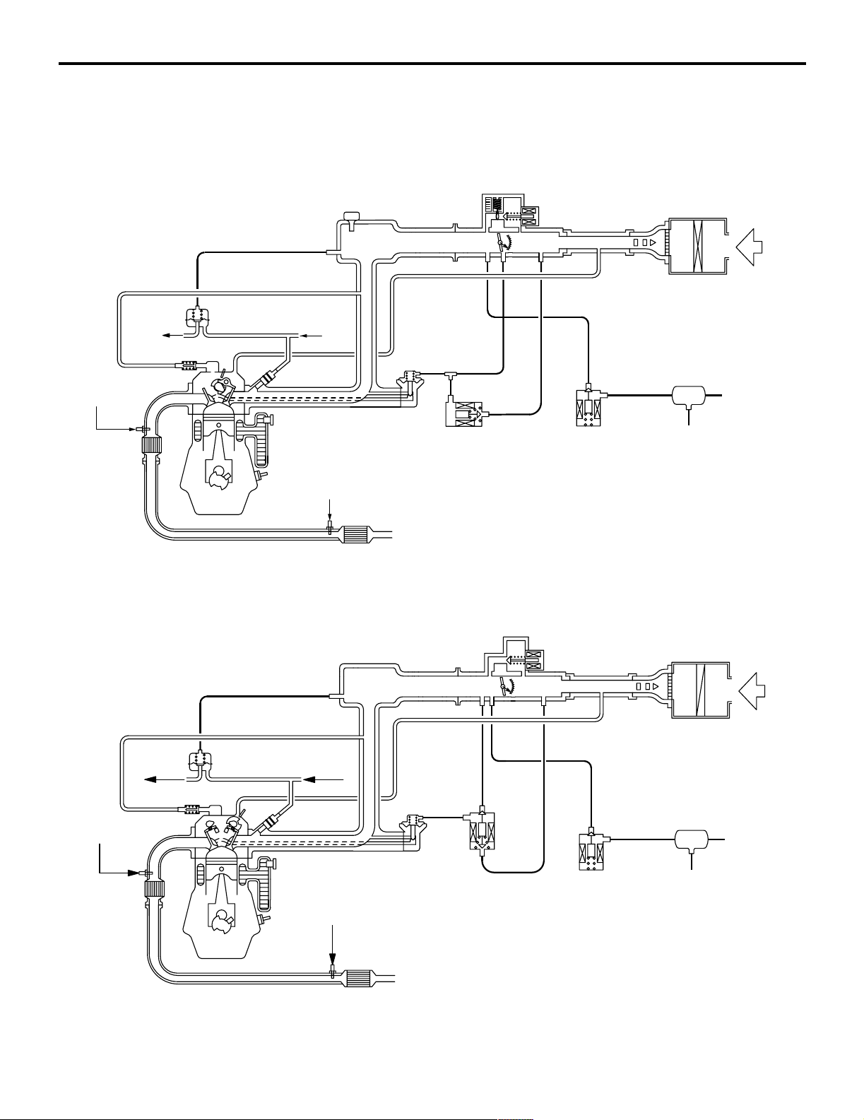
VACUUM HOSE PIPING DIAGRAM
M1173000900417
<4G1>
To
fuel tank
Oxygen sensor
(front)
Catalytic
converter
Fuel pressure
regulator
Oxygen sensor (rear)
From
fuel pump
EGR valve
EGR control
solenoid valve
Air cleaner
Air
Canister
Purge control
solenoid valve
<4G6>
To
fuel tank
Oxygen sensor
(front)
Catalytic
converter
PCV valve
Fuel pressure
regulator
Catalytic
converter
From
fuel pump
EGR valve
Oxygen sensor (rear)
Catalytic
converter
EGR control
solenoid valve
Purge control
solenoid valve
Air cleaner
Canister
AK300964
AB
Air
AK204364
AC
Page 9
ENGINE AND EMISSION CONTROL
EMISSION CONTROL <MPI>
17-7
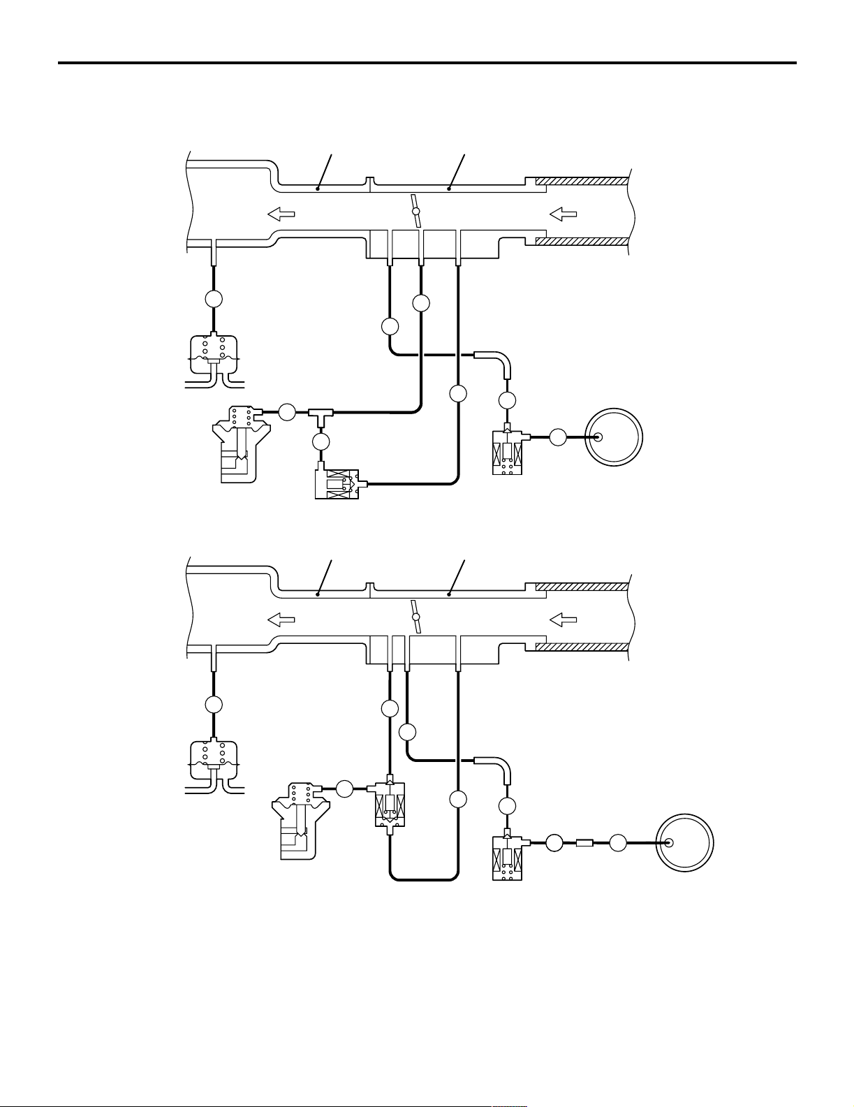
VACUUM CIRC UIT DIA GRAM
<4G1>
To
combustion
chamber
L
Fuel
pressure
regulator
Vacuum hose colour
B: Black
G: Green
R: Red
Y: Yellow
L: Blue
EGR
valve
G
M1173007100263
Intake manifold
G
EGR
control
solenoid
valve
Throttle body
From
air
cleaner
G
R
Y
R
Purge
control
solenoid
valve
Canister
B
AK300765
AB
<4G6>
To
combustion
chamber
Fuel
pressure
regulator
Vacuum hose colour
B: Black
G: Green
R: Red
W: White
Y: Yellow
L: Blue
Intake manifold
L
G
EGR
control
solenoid
EGR
valve
valve
W
R
Throttle body
Y
B
B
Purge
control
solenoid
valve
From
air
cleaner
Canister
B
AK300766
AB
Page 10

17-8
ENGINE AND EMISSION CONTROL
EMISSION CONTROL <MPI>
VACUUM HOSE CHECK
M1173007300159
1. Using the piping diagram as a guide, check to be
sure that the vacuum hoses are correctly
connected.
2. Check the connection condition of the vacuum
hoses, (removed, loose, etc.) and check to be
sure that there are no bends or damage.
VACUUM HOSE INSTALLATION
M1173007200107
1. When connecting the vacuum hoses, they should
be securely inserted onto the nipples.
2. Connect the hoses correctly, using the vacuum
hose piping diagram as a guide.
CRANKCASE EMISSION CONTROL
SYSTEM
GENERAL INFORMATION (CRANKCASE
EMISSION CONTROL SYSTEM)
M1173005000237
The crankcase emission control system prevents
blow-by gases from escaping inside the crankcase
into the atmosphere.
Fresh air is sent from the air cleaner into the
crankcase through the breather hose.
The air becomes mixed with the blow-by gases
inside the crankcase.
The blow-by gas inside the crankcase is drawn into
the intake manifold through the positive crankcase
ventilation (PCV) valve.
The PCV valve lifts the plunger according to the
intake manifold vacuum so as to regulate the flow of
blow-by gas properly.
In other words, the blow-by gas flow is regulated
during low load engine operation to maintain engine
stability, while the flow is increased during high load
operation to improve the ventilation performance.
SYSTEM DIAGRAM
Ventilation hose
PCV valve
Breather hose
Air cleaner
AK204365
Air
AB
Page 11

ENGINE AND EMISSION CONTROL
EMISSION CONTROL <MPI>
17-9
COMPONENT LOCATION (CRANKCASE
EMISSION CONTROL SYSTEM)
M1173007400208
<4G1>
PCV valve
AK300767
<4G6>
PCV valve
AK204366
AB
AC
POSITIVE CRANKCASE VENTILATION
(PCV) VALVE CHECK
M1173001200187
PCV valve
AK100010
AC
1. Insert a thin rod into the PCV valve from the side
shown in the illustration (rocker cover installation
side), and move the rod back and forth to check
that the plunger moves.
2. If the plunger does not move, there is a clogging
in the PCV valve. In this case, clean or replace
the PCV valve.
EVAPORATIVE EMISSION CONTROL
SYSTEM
POSITIVE CRANKCASE VENTILATION
SYSTEM CHECK
M1173001100179
1. Remove the ventilation hose from the PCV valve.
2. Remove the PCV valve from the rocker cover.
3. Reinstall the PCV valve at the ventilation hose.
4. Start the engine and run at idle.
PCV valve
AKX00336
5. Place a finger at the opening of the PCV valve
and check that vacuum of the intake manifold is
felt.
NOTE: At this moment, the plunger in the PCV
valve moves back and forth.
6. If vacuum is not felt, clean the PCV valve or
replace it.
AD
GENERAL INFORMATION (EVAPORATIVE
EMISSION CONTROL SYSTEM)
M1173005100405
The evaporative emission control system prevents
fuel vapours generated in the fuel tank from escaping
into the atmosphere.
Fuel vapours from the fuel tank flow through the fuel
tank pressure control valve and vapour pipe/hose to
be stored temporarily in the canister.
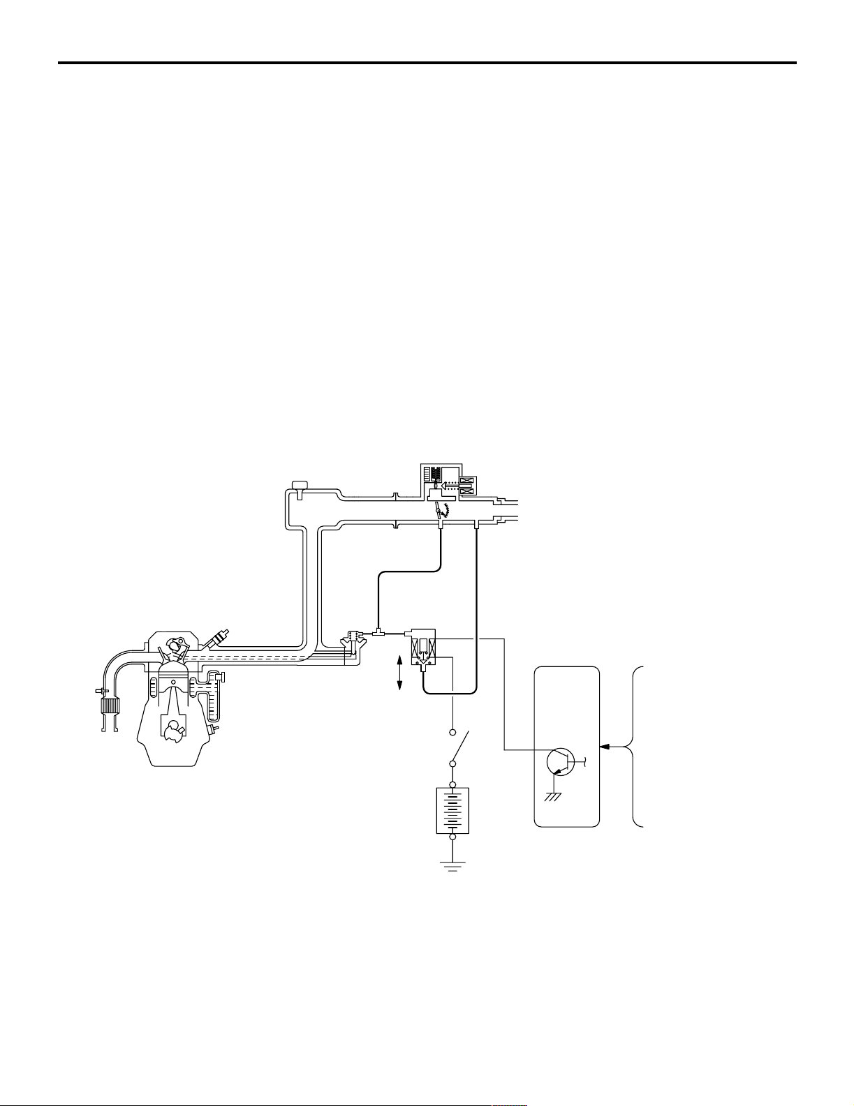
When driving the vehicle, fuel vapours stored in the
canister flow through the purge solenoid and purge
port and go into the intake manifold to be sent to the
combustion chamber.
When the engine coolant temperature is low or when
the intake air quantity is small (when the engine is at
idle, for example), the engine control unit turns the
purge solenoid off to shut off the fuel vapour flow to
the intake manifold.
This does not only insure the driveability when the
engine is cold or running under low load but also
stabilize the emission level.
Page 12
17-10
SYSTEM DIAGRAM
From
fuel
tank
Canister
ENGINE AND EMISSION CONTROL
EMISSION CONTROL <MPI>
Throttle body
Engine-ECU <4G1-M/T, 4G6>,
Engine-A/T-ECU <4G1-A/T>
OFF
Purge
control
ON
solenoid
valve
Battery
Control
relay
Manifold absolute pressure
(MAP) sensor <4G1>
Air flow sensor <4G6>
Engine coolant
temperature sensor
Intake air
temperature sensor
Barometric pressure
sensor <4G6>
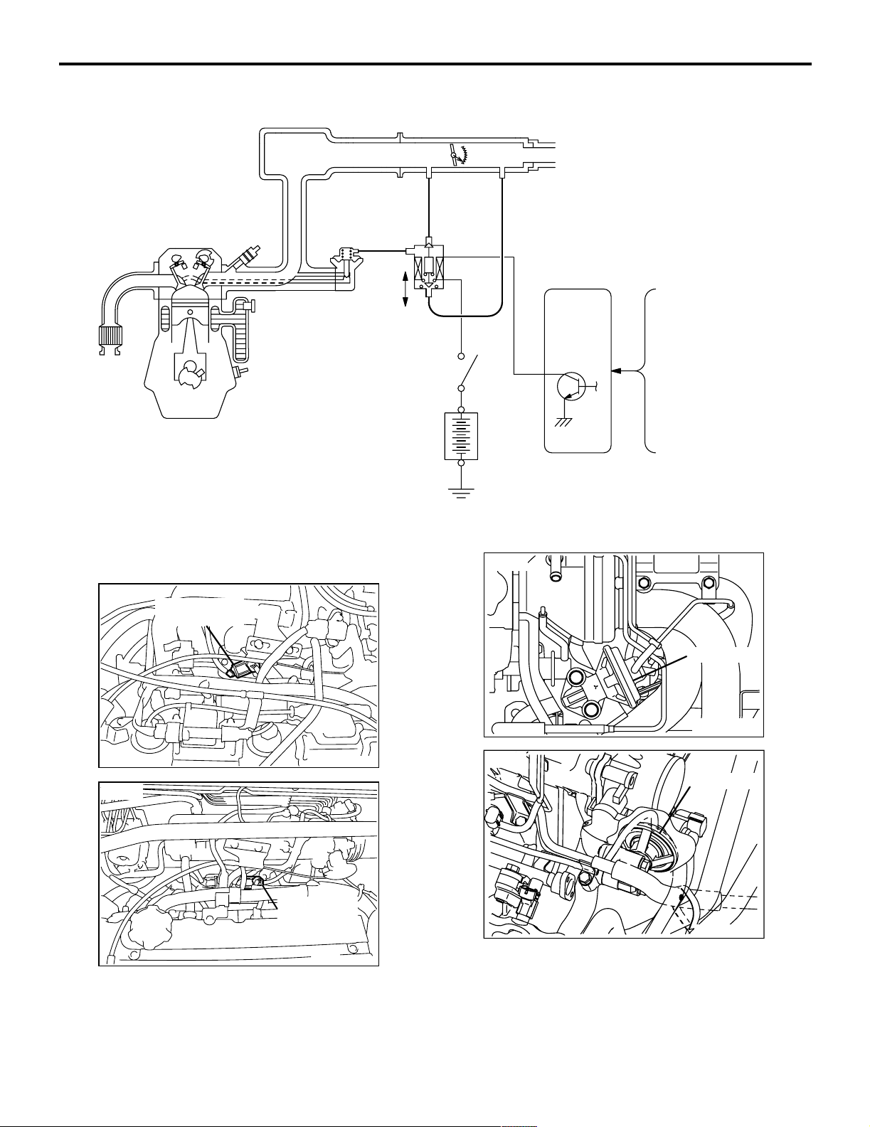
COMPONENT LOCATION (EVAPORATIVE
EMISSION CONTROL SYSTEM)
M1173007500216
<4G1>
Purge control
solenoid valve
<4G6>
AK300769
AB
AK204367
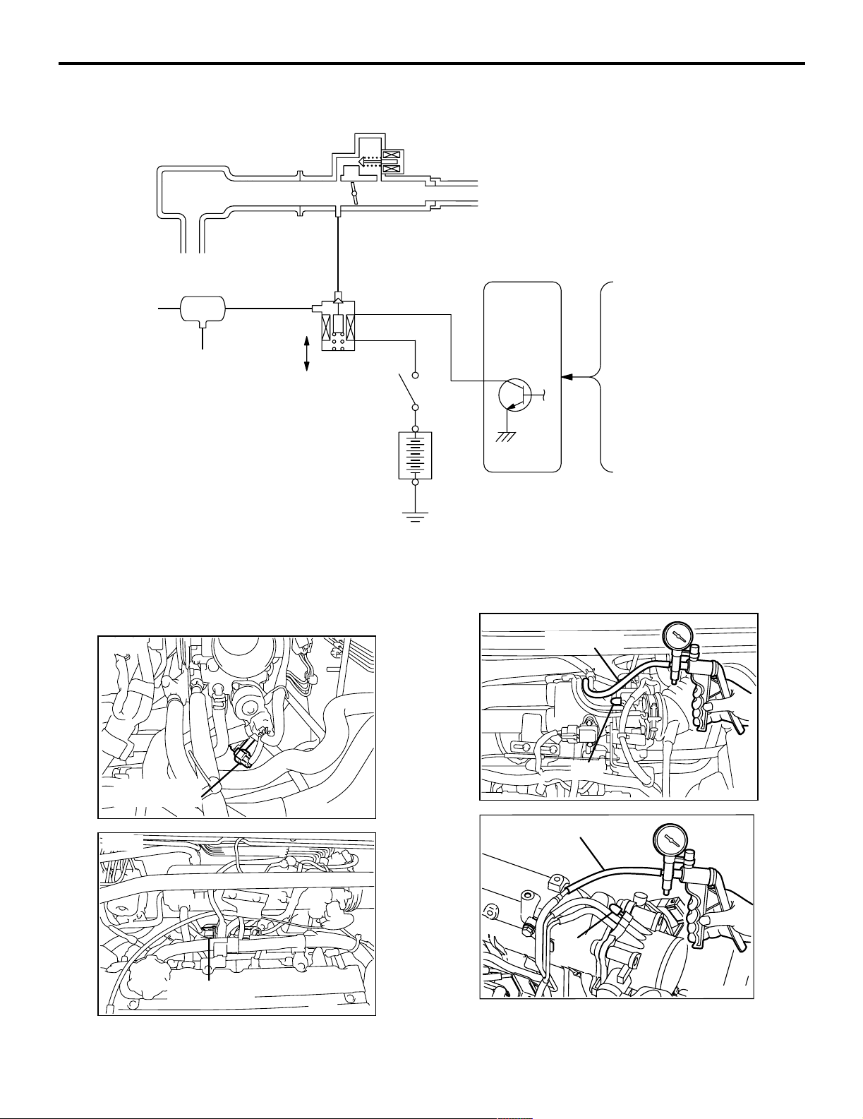
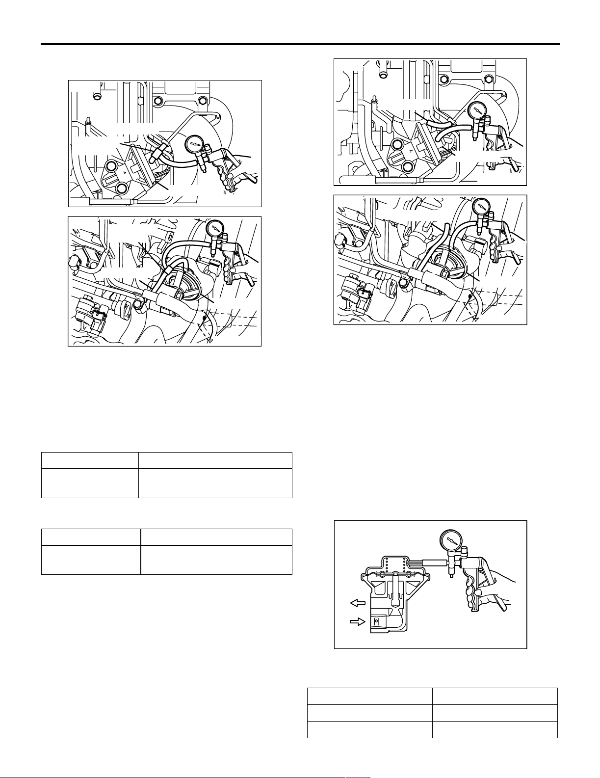
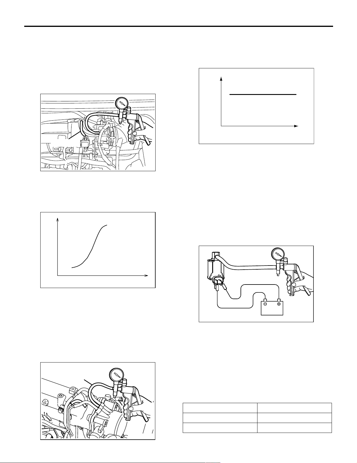
PURGE CONTROL SYSTEM CHECK
M1173001400299
<4G1>
Vacuum hose
Plug
<4G6>
AK300771
Vacuum hose
Plug
AB
AC
Purge control
solenoid valve
AK300770
AB
AK300772
AB
Page 13
ENGINE AND EMISSION CONTROL
EMISSION CONTROL <MPI>
1. Disconnect the vacuum hose (red stripe) from
throttle body and connect it to a hand vacuum
pump.
2. Plug the nipple from which the vacuum hose was
removed.
3. When the engine is cold or hot, apply a vacuum of
53 kPa, and check the condition of the vacuum.
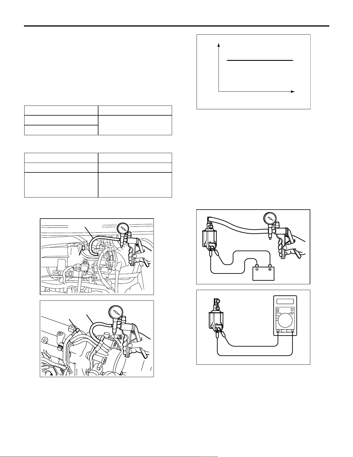
17-11
Vacuum
When engine is cold
(Engine coolant temperature: 40°C or less)
Engine condition Normal condition
At idle Vacuum is maintained.
3,000 r/min
When engine is hot
(Engine coolant temperature: 80°C or higher)
Engine condition Normal condition
At idle Vacuum is maintained.
3,000 r/min (within 3
Vacuum will leak.
minutes after engine
starts)
PURGE PORT VACUUM CHECK
M1173001500177
<4G1>
Vacuum hose
Plug
Engine speed (r/min)
AK100011
AC
3. Start the engine.
4. Check that a fairly constant negative pressure is
generated regardless of the engine speed.
5. If no negative pressure is generated, the port is
probably blocked and should be cleaned.
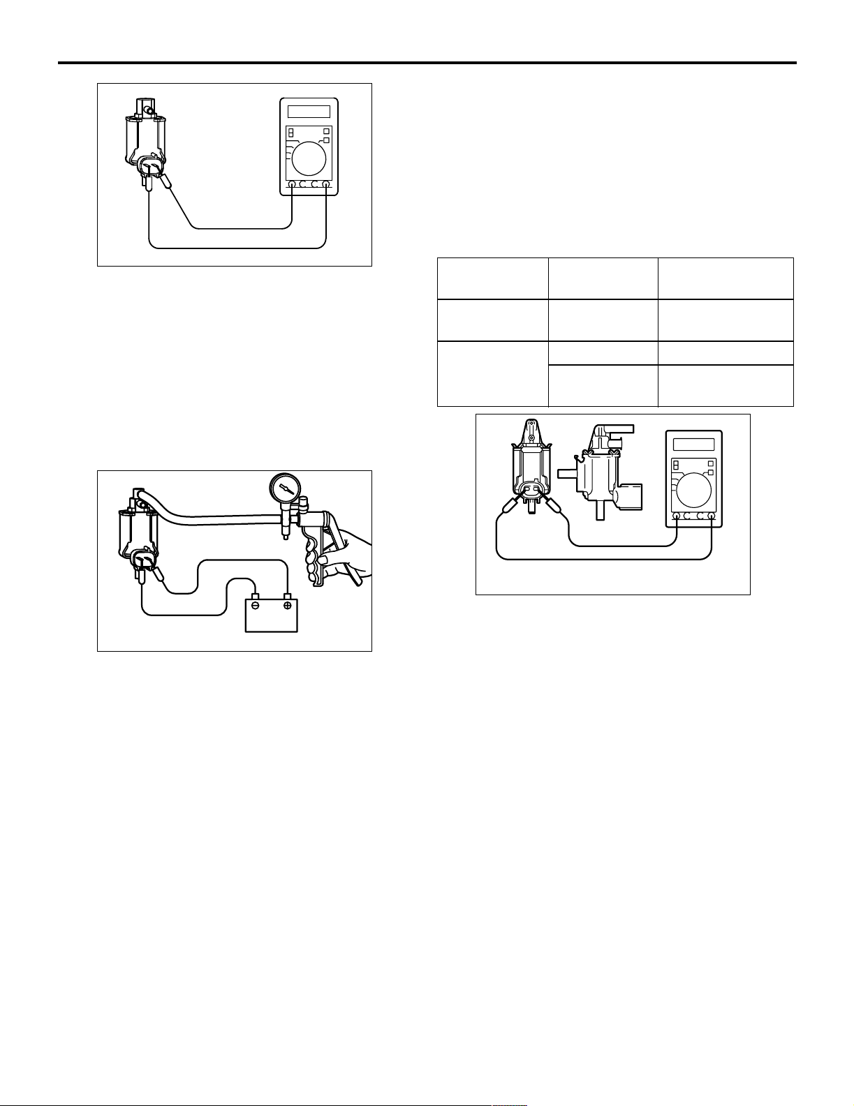
PURGE CONTROL SOLENOID VALVE
CHECK
M1173001700193
NOTE: When disconnecting the vacuum hose,
always make a mark so that it can be reconnected at
original position.
A
AK300773
<4G6>
Vacuum hose
Plug
AK300774
AB
AB
1. Disconnect the vacuum hose (red stripe) from the
throttle body and connect a hand vacuum pump to
the nipple.
2. Plug the vacuum hose (red stripe).
Battery
AK100012
AC
AK100013
1. Disconnect the vacuum hose from the solenoid
valve.
2. Disconnect the harness connector.
3. Connect a hand vacuum pump to nipple (A) of the
solenoid valve (refer to the illustration at left).
Page 14
17-12
ENGINE AND EMISSION CONTROL
EMISSION CONTROL <MPI>
4. Check airtightness by applying a vacuum with
voltage applied directly from the battery to the
purge control solenoid valve and without applying
voltage.
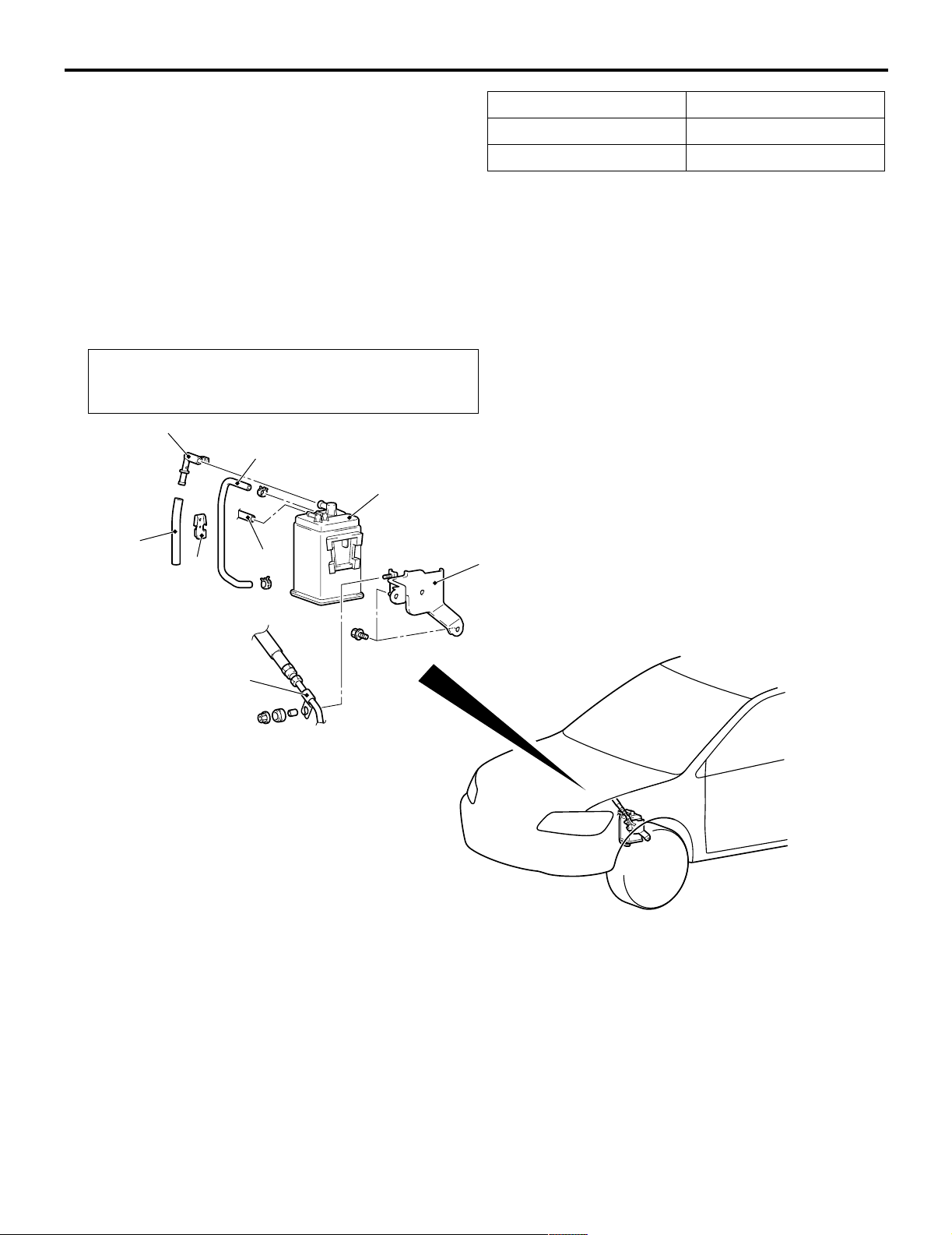
FUEL VAPOUR CANISTER REMOVAL
AND INSTALLATION
M1173004200153
Pre-removal and Post-installation Operation
Air Cleaner Assembly Removal and Installation (Refer to
GROUP 15 P.15-3).
3
2
6
4
5
1
Battery voltage Normal condition
Applied Vacuum leaks
Not applied Vacuum maintained
5. Measure the resistance between the terminals of
the solenoid valve.
Standard value: 30 − 34 Ω (at 20°C)
8
7
Removal steps
1. Emission vacuum hose connection
2. Fuel vapour control line hose
3. Fuel vapour control check valve
4. Fuel vapour control line hose
AC208253
Removal steps (Continued)
5. Fuel vapour control line clamp
6. Fuel vapour canister
7. Fuel high-pressure hose clamp
8. Fuel vapour canister bracket
AD
Page 15
ENGINE AND EMISSION CONTROL
EMISSION CONTROL <MPI>
17-13
EXHAUST GAS RECIRCULATION
(EGR) SYSTEM
GENERAL INFORMATION (EGR SYSTEM)
M1173005200327
The exhaust gas recirculation (EGR) system lowers
the nitrogen oxide (NOx) emission level.
When the air/fuel mixture combustion temperature is
high, a large quantity of nitrogen oxides (NOx) is
generated in the combustion chamber.
Therefore, this system recirculates part of emission
gas from the exhaust port of the cylinder head to the
combustion chamber through the intake manifold to
decrease the air/fuel mixture combustion
temperature, resulting in reduction of NOx.
SYSTEM DIAGRAM
<4G1>
The EGR flow rate is controlled by the EGR valve so
as not to decrease the driveability.
OPERATION
The EGR valve is being closed and does not
recirculate exhaust gases under one of the following
conditions.
Otherwise, the EGR valve is opened and recirculates
exhaust gases.
• The engine coolant temperature is low.
• The engine is at idle.
• The throttle valve is widely opened.
EGR valve
OFF
ON
Battery
EGR
control
solenoid
valve
Control
relay
Engine-ECU <M/T>,
Engine-A/T-ECU <A/T>
Manifold absolute
pressure (MAP) sensor
Engine coolant
temperature sensor
Crank angle sensor
AK300775
AB
Page 16
17-14
<4G6>
ENGINE AND EMISSION CONTROL
EMISSION CONTROL <MPI>
EGR
control
Solenoid
valve
OFF
EGR valve
ON
Battery
COMPONENT LOCATION (EGR SYSTEM)
M1173007600224
<4G1>
EGR control
solenoid valve
Control
relay
<4G1>
Engine-ECU
Barometric pressure
sensor
Air flow sensor
Engine coolant
temperature sensor
Crank angle sensor
AK302349
EGR valve
AB
<4G6>
AK300776
EGR control
solenoid valve
AK300778
AB
AB
<4G6>
AK300777
EGR valve
AK300779
AB
AB
Page 17
ENGINE AND EMISSION CONTROL
EMISSION CONTROL <MPI>
17-15
EGR SYSTEM CHECK
M1173002600348
<4G1>
Green stripe
Three-way
terminal
<4G6>
EGR valve
Three-way
terminal
Green stripe
AK300780
EGR valve
AK300781
1. Disconnect the vacuum hose (Green stripe) from
the EGR valve, and then connect a hand vacuum
pump via the three-way terminal.
2. When the engine is hot or cold, check the
condition of vacuum by racing the engine.
When engine is cold
(Engine coolant temperature: 20°C or less)
Throttle valve Normal vacuum condition
Open quickly No vacuum will generate (the
same as barometric pressure.)
When engine is hot
(Engine coolant temperature: 80°C or higher)
Throttle valve Normal vacuum condition
AB
AB
<4G1>
Green stripe
EGR valve
AK300782
<4G6>
Green stripe
EGR valve
AK300783
AB
AB
4. Connect the hand vacuum pump to the EGR
valve nipple.
5. Check whether the engine stalls or the idling is
unstable when a vacuum of 30 kPa or higher is
applied during idling.
EGR VALVE CHECK
M1173002800223
1. Remove the EGR valve and inspect for sticking,
carbon deposits, etc. If found, clean with a
suitable solvent so that the valve seats correctly.
2. Connect a hand vacuum pump to the EGR valve.
3. Apply 67 kPa of vacuum, and check that the
vacuum is maintained.
Open quickly It will momentarily rise over 13
kPa
3. Disconnect the three-way terminal.
AKX00348
4. Apply a vacuum and check the passage of air by
blowing through one side of the EGR passage.
Vacuum Passage of air
5.3 kPa or less Air is not blown out
27 kPa or more Air is blown out
Page 18
17-16
ENGINE AND EMISSION CONTROL
EMISSION CONTROL <MPI>
5. Replace the gasket, and tighten to the specified
torque.
Tightening torque:
<4G1> 21 ± 4 N⋅m
<4G6> 20 ± 2 N⋅m
EGR PORT VACUUM CHECK <4G1>
M1173002900167
Green strip
AK300784
1. Disconnect the vacuum hose (Green stripe) from
the throttle body EGR vacuum nipple and connect
a hand vacuum pump to the nipple.
2. Plug the vacuum hose (Green stripe).
Vacuum
AB
1. Disconnect the vacuum hose (White stripe) from
the throttle body EGR vacuum nipple and connect
a hand vacuum pump to the nipple.
2. Plug the vacuum hose (White stripe).
Vacuum
Engine speed (r/min)
AK100011
AC
3. Start the engine.
4. Check that a fairly constant negative is generated
regardless of the engine speed.
5. If no negative pressure is generated, the port is
probably blocked and should be cleaned.
EGR CONTROL SOLENOID VALVE
CHECK <4G1>
M1173003100238
NOTE: When disconnecting the vacuum hose,
always make a mark so that it can be reconnected at
original position.
A
Engine speed (r/min)
AK201224AB
3. Start the engine and check that, after raising the
engine speed by racing the engine, purge vacuum
raises according to engine speed.
NOTE: If there is a problem with change in
vacuum, the throttle body purge port may be
clogged and require cleaning.
EGR PORT VACUUM CHECK <4G6>
M1173002900156
White stripe
AK300786
AB
B
Battery
AKX00351
AE
1. Disconnect the vacuum hose from the solenoid
valve.
2. Disconnect the harness connector.
3. Connect a hand vacuum pump to nipple (A) of the
solenoid valve (refer to the illustration at left).
4. Check air tightness by applying a vacuum with
voltage applied directly from the battery to the
EGR control solenoid valve and without applying
voltage.
Battery voltage Normal condition
Applied Vacuum leaks
Not applied Vacuum maintained
Page 19
ENGINE AND EMISSION CONTROL
EMISSION CONTROL <MPI>
AKX00352
5. Measure the resistance between the terminals of
the solenoid valve.
Standard value: 29 − 35 Ω (at 20°C)
EGR CONTROL SOLENOID VALVE
CHECK <4G6>
M1173003100249
NOTE: When disconnecting the vacuum hose,
always make a mark so that it can be reconnected at
original position.
17-17
1. Disconnect the vacuum hose from the solenoid
valve.
2. Disconnect the harness connector.
3. Connect a hand vacuum pump to nipple (A) of the
solenoid valve (refer to the illustration at left).
4. Check air tightness by applying a vacuum with
voltage applied directly from the battery to the
EGR control solenoid valve and without applying
voltage.
Battery
voltage
Not applied Open Vacuum
Applied Open Vacuum leaks
B nipple
Normal condition
condition
maintained
Closed Vacuum
maintained
A
B
C
Battery
AK201251AB
5. Measure the resistance between the terminals of
the solenoid valve.
AK100016
Standard value: 29 − 35 Ω (at 20°C)
Page 20
17-18
ENGINE AND EMISSION CONTROL
EMISSION CONTROL <MPI>
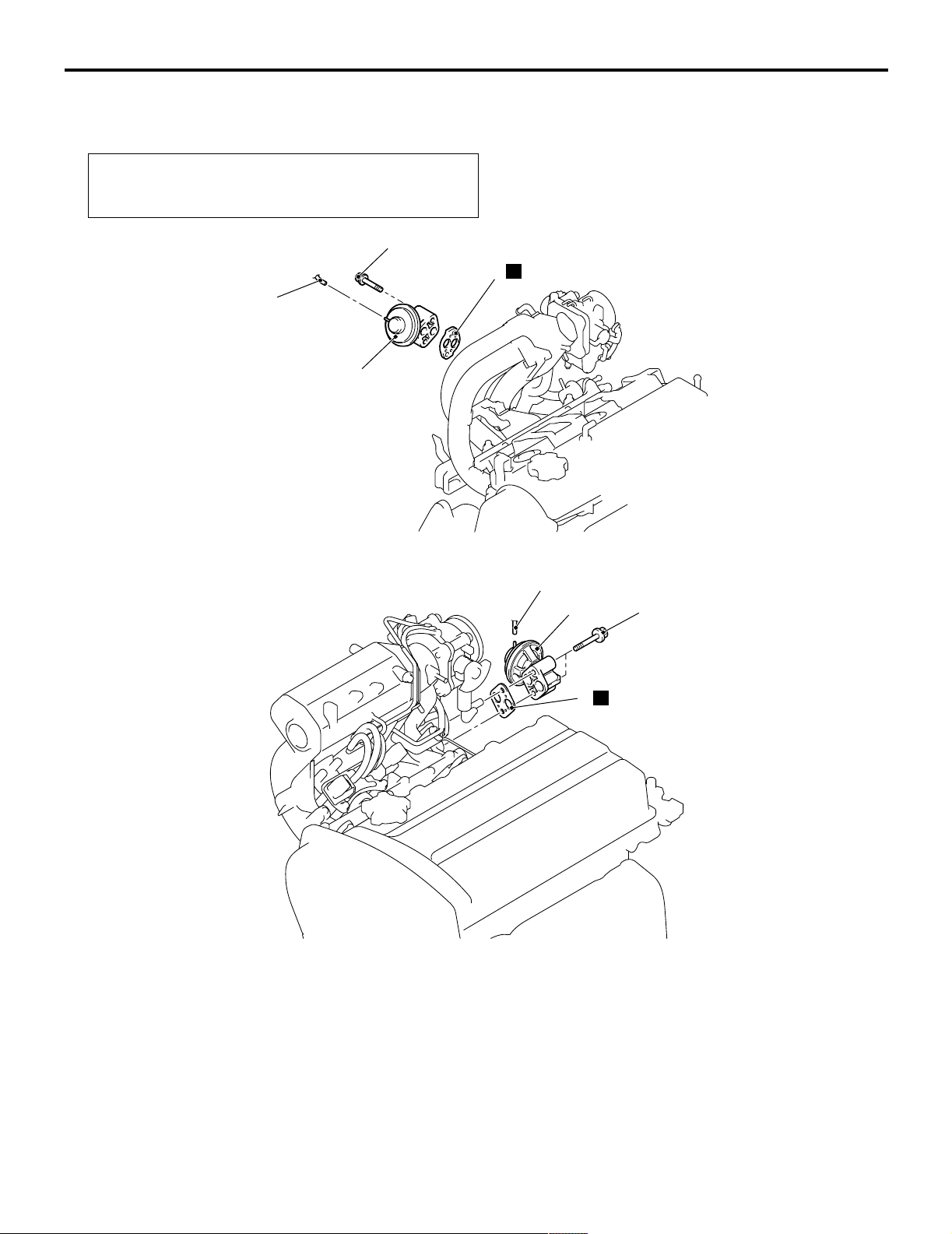
EXHAUST GAS RECIRCULATION (EGR)
VALVE REMOVAL AND INSTALLATION
M1173010500175
Pre-removal and Post-installation Operation
Air Cleaner Assembly Removal and Installation (Refer to
GROUP 15 P.15-3).
<4G1>
<4G6>
21 ± 4 N·m
N
3
1
2
AC208130
AC
1
2
19 ± 3 N·m
Removal steps
1. Emission vacuum hose connection
CATALYTIC CONVERTER
REMOVAL AND INSTALLATION
M1173003900386
Refer to GROUP 15 - Exhaust Pipe and Main Muffler P.15-11.
N
3
Removal steps (Continued)
2. EGR valve
3. EGR valve gasket
AC301219
AC
Page 21

GROUP 13
FUEL
CONTENTS
MULTIPORT FUEL INJECTION (MPI) <4G1> . . . . . . . . . . . . . . 13A
MULTIPORT FUEL INJECTION (MPI) <4G6> . . . . . . . . . . . . . . 13B
13-1
FUEL SUPPLY . . . . . . . . . . . . . . . . . . . . . . . . . . . . . . . . . . . . . . 13C
Page 22

NOTES
Page 23

GROUP 32
POWER PLANT
MOUNT
CONTENTS
32-1
GENERAL INFORMATION . . . . . . . . 32-2
SERVICE SPECIFICATION . . . . . . . . 32-3
SPECIAL TOOL . . . . . . . . . . . . . . . . . 32-3
ENGINE MOUNTING . . . . . . . . . . . . . 32-4
REMOVAL AND INSTALLATION . . . . . . . . 32-4
TRANSMISSION MOUNTING . . . . . . 32-5
REMOVAL AND INSTALLATION . . . . . . . . 32-5
ENGINE ROLL STOPPER,
CENTERMEMBER . . . . . . . . . . . . . . . 32-7
REMOVAL AND INSTALLATION . . . . . . . . 32-7
CROSSMEMBER . . . . . . . . . . . . . . . . 32-8
REMOVAL AND INSTALLATION . . . . . . . . 32-8
Page 24
32-2
POWER PLANT MOUNT
GENERAL INFORMATION
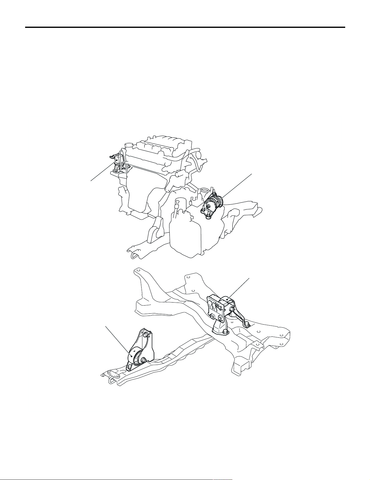
GENERAL INFORMATION
The engine mounting system employs the inertial
axis four-point suspension method, which is field
proven.
• The optimised locations of the front and rear roll
mounts well distribute their loads thereby
reducing engine idling vibrations.
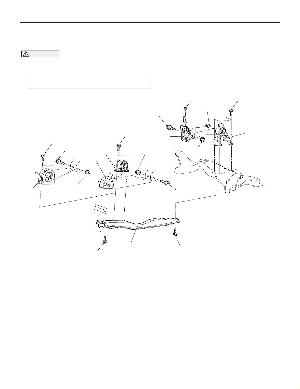
CONSTRUCTION DIAGRAM
Engine front
mounting bracket
• The fore-and-aft, liquid-filled engine mount of
M1321000100340
cylinder type is adopted to reduce engine shake
for improved riding comfort.
Transmission mounting
body side bracket
Engine front roll stopper bracket
Engine rear roll stopper bracket
Y0290AU
AC107318
AC303563
AB
Page 25
POWER PLANT MOUNT
SERVICE SPECIFICATION
SERVICE SPECIFICATION
Item Standard value
Protruding length of stabilizer link thread part mm 22 ± 1.5
SPECIAL TOOL
Tool Numb er Name Use
MB991897 Ball joint remover Knuckle and tie rod end ball joint
disconnection
NOTE: Steering linkage puller
(MB990635 or MB991113) is also
AC106827
available to disconnect knuckle and
tie rod end ball joint.
32-3
M1321000300333
M1321000600378
Page 26
32-4
POWER PLANT MOUNT
ENGINE MOUNTING
ENGINE MOUNTING
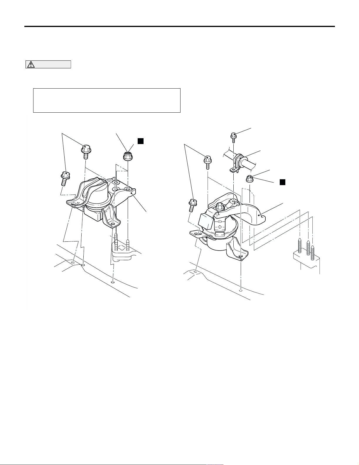
REMOVAL AND INSTALLATION
M1321001100440
CAUTION
*: Indicates parts which should be initially tightened, and then fully tightened after placing the vehicle
horizontally and loading the full weight of the engine on the vehicle body.
Pre-removal Operation
Raise the engine and transmission assembly until its weight
is not applied to the insulator, and support it securely.
<4G1> <4G6>
44 ± 10 N·m*
67 ± 7 N·m*
N
2
44 ± 10 N·m*
3
12 ± 2 N·m
1
67 ± 7 N·m*
N
2
3
AC303999 AC303968
Removal steps
1. Pressure hose clamp <4G6>
AC304304
Removal steps (Continued)
2. Self-locking nuts
3. Engine front mounting bracket
AB
Page 27
POWER PLANT MOUNT
TRANSMISSION MOUNTING
TRANSMISSION MOUNTING
32-5
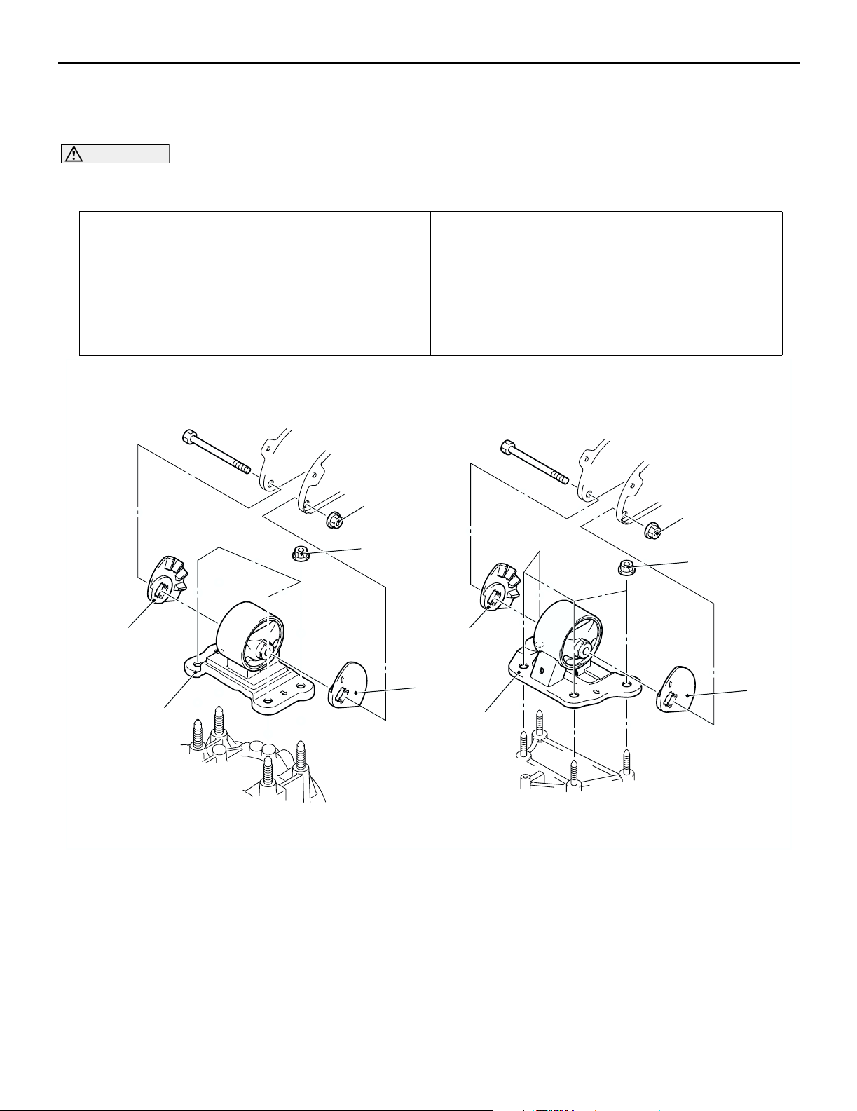
REMOVAL AND INSTALLATION
M1321001400430
CAUTION
*: Indicates parts which should be initially tightened, and then fully tightened after placing the vehicle
horizontally and loading the full weight of the engine on the vehicle body.
Pre-removal Operation
• Raise the engine and transmission assembly until its
weight is not applied to the insulator, and support it
securely.
• Battery and Battery tray Removal
• Air Cleaner Removal (Refer to GROUP 15, Air Cleaner
P.15-3).
• Engine Rear Roll Stopper Bracket Removal (Refer to
P.32-7).
<M/T> <A/T>
80 ± 7 N·m*
Post-installation Operation
• Engine Rear Roll Stopper Bracket Installation (Refer to
P.32-7).
• Air Cleaner Installation (Refer to GROUP 15, Air Cleaner
P.15-3).
• Battery and Battery tray Installation
80 ± 7 N·m*
2
>>A<<
1
Removal steps
1. Transmission mounting body side
bracket
2. Transmission mounting stopper
47 ± 7 N·m*
2
AC303988
47 ± 7 N·m*
2
2
1
AC303989
AC304258
AB
Page 28
32-6
POWER PLANT MOUNT
TRANSMISSION MOUNTING
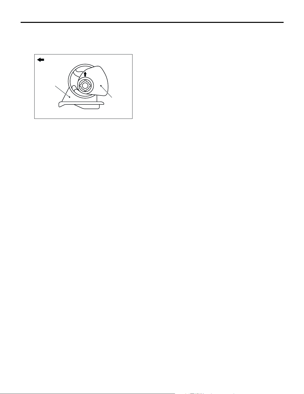
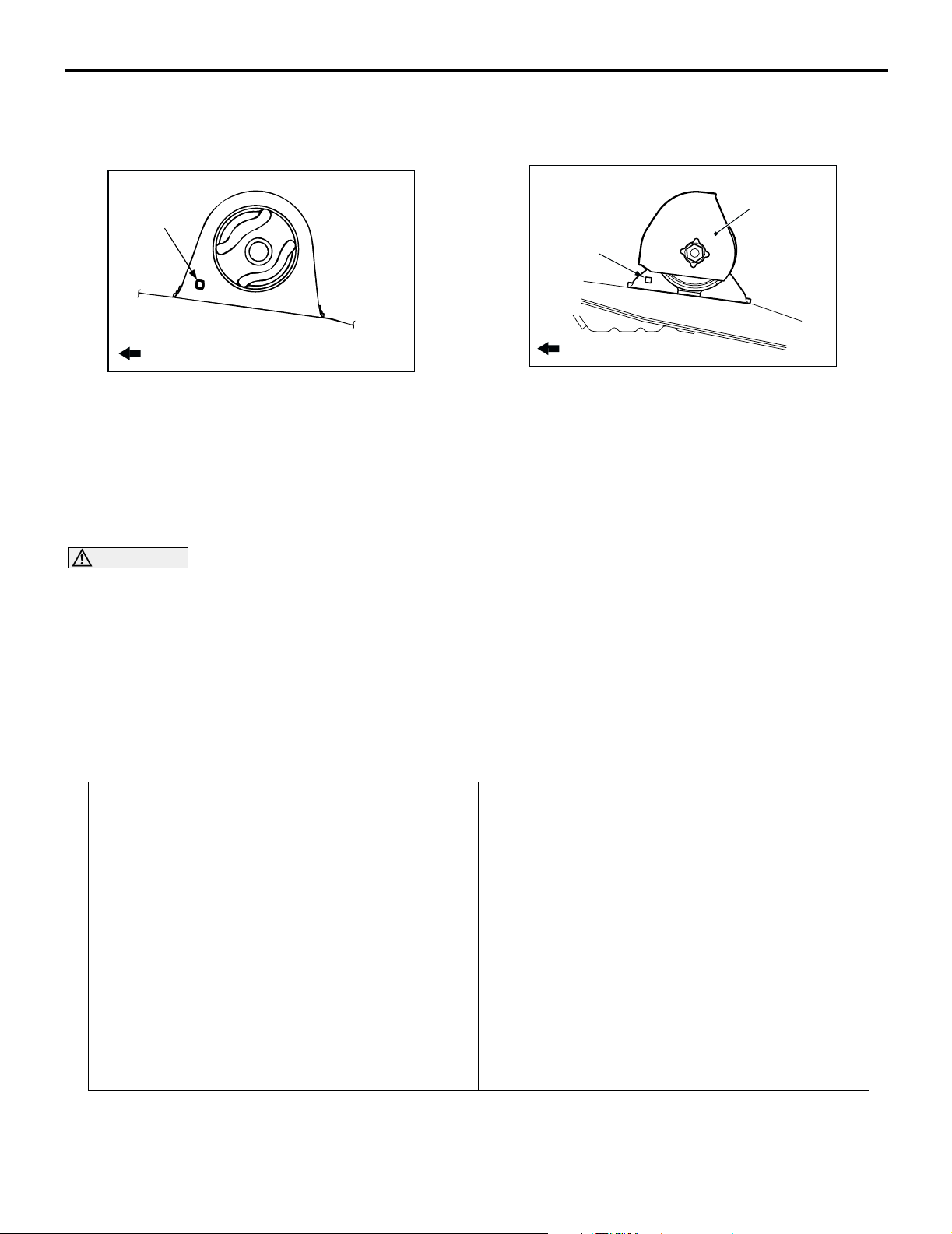
INSTALLATION SERVICE POINT
>>A<< TRANSMISSION MOUNTING
STOPPER INSTALLATION
Engine side
Transmission
mounting body
side bracket
Transmission
mounting
stopper
AC200645
AB
Install the transmission mounting stopper so that its
arrow points upward.
Page 29
POWER PLANT MOUNT
ENGINE ROLL STOPPER, CENTERMEMBER
ENGINE ROLL STOPPER, CENTERMEMBER
32-7
REMOVAL AND INSTALLATION
M1321002300287
CAUTION
*: Indicates parts which should be initially tightened, and then fully tightened after placing the vehicle
horizontally and loading the full weight of the engine on the vehicle body.
Pre-removal and Post-installation Operation
Under Cover Removal and Installation
45 ± 5 N·m*
7
<4G1> <4G6>
45 ± 5 N·m*
1
3
2
45 ± 5 N·m*
5
52 ± 7 N·m*
11 ± 1 N·m
69 ± 10 N·m
6
52 ± 7 N·m*
3
>>B<<
>>A<<
52 ± 7 N·m*
4
69 ± 10 N·m
Engine front roll stopper bracket
and centermember removal
steps
1. Engine front roll stopper bracket
connecting bolt
Centermember and engine front roll
•
stopper bracket assembly
2. Engine mounting cushion stopper
<4G6>
3. Engine front roll stopper bracket
4. Centermember
1
69 ± 10 N·m
5. Engine rear roll stopper bracket
6. Transmission case rear roll stopper
7. Engine rear roll stopper bracket
AC303978
AC304309
Engine rear roll stopper bracket
removal steps
connecting bolt
bracket
AB
Page 30
32-8
POWER PLANT MOUNT
CROSSMEMBER
INSTALLATION SERVICE POINTS
>>A<< ENGINE FRONT ROLL STOPPER
BRACKET INSTALLATION
Hole
>>B<< ENGINE MOUNTING CUSHION
STOPPER INSTALLATION <4G6>
Engine mounting
cushion stopper
Hole
Front of vehicle
AC005918
AC
Install the engine front roll stopper bracket so that its
hole points towards the front side of the vehicle.
Install the engine mounting cushion stopper as
shown.
Front of vehicle
AC304315
AB
CROSSMEMBER
REMOVAL AND INSTALLATION
CAUTION
• Before removing the steering wheel and air bag module assembly, always refer to GROUP 52B Service Precautions P.52B-5, Air bag Module and Clock Spring P.52B-210. Also, set the front
wheels so that they are facing straight forward, and remove the ignition key. If you fail to do this,
the SRS clock spring will be damaged, causing the SRS air bag to be inoperative and serious
injury.
1
: Indicates parts which should be initially tightened, and then fully tightened after placing the
• *
vehicle horizontally and loading the full weight of the engine on the vehicle body.
2
: Indicates parts which should be temporarily tightened, and then fully tightened with the vehicle
• *
on the earth in the unladen condition.
Pre-removal Operation
• Centermember Removal (Refer to P.32-7).
• Front Exhaust Pipe Removal (Refer to GROUP 15,
Exhaust Pipe and Main Muffler P.15-11).
• Stee ring Wheel Air Bag Module Assembly Removal
(Refer to GROUP 37, Steering Wheel P.37-17).
• Power Steering Fluid Draining (Refer to GROUP 37,
On-vehicle Service P.37-13).
M1321003200368
Post-installation Operation
• Front Exhaust Pipe Installation (Refer to GROUP 15,
Exhaust Pipe and Main Muffler P.15-11).
• Centermember Installation (Refer to P.32-7).
• Clock Spring Centring (Refer to GROUP 52B, Air Bag
Modules and Clock Spring P.52B-210).
• Steering Wheel Air Bag Module Assembly Installation
(Refer to GROUP 37, Steering Wheel P.37-17).
• Power Steering Fluid Supplying (Refer to GROUP 37,
On-vehicle Service P.37-13).
• Power Steering Fluid Line Bleeding (Refer to GROUP 37,
On-vehicle Service P.37-13).
• Press the dust cover with a finger to check whether the
dust cover cracked or damaged.
• Checking Steering Wheel Position with Wheels Straight
Ahead.
• Front Wheel Alignment Check and Adjustment (Refer to
GROUP 33, On-vehicle Service P.33-5).
Page 31

<L.H. drive vehicles>
POWER PLANT MOUNT
CROSSMEMBER
32-9
6
52 ± 7 N·m*
45 ± 5 N·m*
7
1
12 ± 2 N·m
70 ± 10 N·m
12
1
8
16
21 ± 4 N·m
10
70 ± 10 N·m
14
11
4
N
57 ± 7 N·m
9
5
18 ± 2 N·m
N
13
25 ± 4 N·m
15
21 ± 4 N·m
N
2
108 ± 10 N·m
3
17
>>B<<
186 ± 10 N·m*
Removal steps
1. Lower arm and knuckle connection
2. Self-locking nut
3. Lower arm assembly
4. Shaft cover
5. Steering shaft assembly and gear
box connecting bolt
6. Engine rear roll stopper bracket
connection bolt
7. Engine rear roll stopper bracket
8. Return hose connection
2
167 ± 9 N·m
49 ± 10 N·m
<<A>>
<<B>>
>>A<<
1
AC304000
Removal steps (Continued)
9. Eye bolt
10. Pressure hose connection
11. Gasket
12. Clamp
13. Self-locking nut
14. Tie rod end and knuckle connection
Crossmember assembly
•
15. Stabilizer bar
16. Steering gear and linkage
17. Crossmember
AB
Page 32

32-10
<R.H. drive vehicles>
POWER PLANT MOUNT
CROSSMEMBER
12
52 ± 7 N·m*¹
45 ± 5 N·m*¹
13
16
8
57 ± 7 N·m
5
N
6
15
7
4
11
9
18 ± 2 N·m
5.0 ± 1.0 N·m
70 ± 10 N·m
N
10
25 ± 4 N·m
14
21 ± 4 N·m
N
2
3
108 ± 10 N·m
>>B<<
186 ± 10 N·m*²
167 ± 9 N·m
Removal steps
1. Lower arm and knuckle connection
2. Self-locking nut
3. Lower arm assembly
4. Eye bolt
5. Pressure hose connection
6. Gasket
7. Return hose connection
8. Shaft cover
9. Steering shaft assembly and gear
box connecting bolt
49 ± 10 N·m
<<A>>
<<B>>
>>A<<
1
AC101614
Removal steps (Continued)
10. Self-locking nut
11. Ti e r od end a nd knu c k le conn e c tion
12. Engine rear roll stopper bracket
connection bolt
Crossmember assembly
•
13. Engine rear roll stopper bracket
14. Stabilizer bar
15. Steering gear and linkage
16. Crossmember
AE
Page 33

POWER PLANT MOUNT
CROSSMEMBER
32-11
REMOVAL SERVICE POINTS
<<A>> TIE ROD END AND KNUCKLE
DISCONNECTION
CAUTION
• Do not remove the nut from ball joint. Loosen
it and use special tool to avoid possible
damage to ball joint threads.
• Hang special tool with a cord to prevent it
from falling.
Cord
Nut
Ball joint
1. Install the special tool ball joint remover
(MB991897) as shown in the figure.
MB991897
Bolt
AC208247
AD
<<B>> CROSSMEMBER ASSEMBLY
REMOVAL
Piece of wood
Transmission
jack
AC102600
AD
1. Use a transmission jack to hold the crossmember,
and then remove the crossmember mounting nuts
and bolts.
2. Lower the crossmember with the engine rear roll
stopper bracket, the stabilizer bar, the return tube,
and the steering gear.
INSTALLATION SERVICE POINTS
>>A<< STABILIZER
BAR/BUSHING/FIXTURE INSTALLATION
Bolt
Parallel
Knob
Good
Bad
AC106821
AB
2. Turn the bolt and knob as necessary to make the
jaws of the special tool parallel, tighten the bolt by
hand and confirm that the jaws are still parallel.
NOTE: When adjusting the jaws in parallel, make
sure the knob is in the position shown in the
figure.
3. Tighten the bolt with a wrench to disconnect the
tie rod end.
Outside of
vehicle
Bushing (LH)
Approximately
10 mm
Identification
mark
Fixture (LH)
AC006141
AD
Align the stabilizer bar identification mark with the
right end of the bushing (LH).
>>B<< SELF-LOCKING NUT
INSTALLATION
A
AC101741
AC
Tighten the self-locking nut until the stabilizer link
thread part protruding length meets the standard
value.
Standard value (A): 22 ± 1.5 mm
Page 34

NOTES
Page 35

GROUP 15
INTAKE AND
EXHAUST
CONTENTS
15-1
GENERAL INFORMATION . . . . . . . . 15-2
SERVICE SPECIFICATION . . . . . . . . 15-2
SPECIAL TOOL . . . . . . . . . . . . . . . . . 15-2
AIR CLEANER . . . . . . . . . . . . . . . . . . 15-3
REMOVAL AND INSTALLATION . . . . . . . . 15-3
INLET MANIFOLD . . . . . . . . . . . . . . . 15-5
REMOVAL AND INSTALLATION <4G1> . . 15-5
REMOVAL AND INSTALLATION <4G6> . . 15-6
INSPECTION. . . . . . . . . . . . . . . . . . . . . . . . 15-7
EXHAUST MANIFOLD . . . . . . . . . . . . 15-7
REMOVAL AND INSTALLATION <4G1> . . 15-7
REMOVAL AND INSTALLATION <4G6> . . 15-9
INSPECTION. . . . . . . . . . . . . . . . . . . . . . . . 15-10
EXHAUST PIPE AND MAIN
MUFFLER . . . . . . . . . . . . . . . . . . . . . . 15-11
REMOVAL AND INSTALLATION . . . . . . . . 15-11
Page 36

15-2
INTAKE AND EXHAUST
GENERAL INFORMATION
GENERAL INFORMATION
The exhaust pipe is divided into three parts.
SERVICE SPECIFICATION
Item Standard value Limit
Manifold distortion of the installation surface mm 0.15 or less 0.20
SPECIAL TOOL
Tool Numb e r Name Use
MD998770 Oxygen sensor wrench Removal and installation of
engine control oxygen sensor
M1151000100402
M1151000300428
M1151000600399
Page 37

INTAKE AND EXHAUST
AIR CLEANER
AIR CLEANER
15-3
REMOVAL AND INSTALLATION
M1151002100486
CAUTION
Parts marked by * are made of recycled-paper mixed plastic material, so observe the following
precautions.
• Avoid any shock or load to these parts when removing and installing them.
• When installing, securely set the air cleaner cover clamp to the air cleaner body.
NOTE: Parts marked by * are made of recycled-paper mixed plastic material. Dispose of according to state
and local laws.
<4G1>
9.0 ± 1.0 N·m
10*
4.0 ± 1.0 N·m
3*
9*
8*
4.0 ± 1.0 N·m
4
5
1*
12 ± 1 N·m
11
9.0 ± 1.0 N·m
12 ± 1 N·m
Clamp
AC303618
AB
Page 38

15-4
INTAKE AND EXHAUST
AIR CLEANER
<4G6>
1*
10*
9.0 ± 1.0 N·m
12 ± 1 N·m
9*
11
Removal steps
1. Air cleaner intake duct
2. Air cleaner air flow sensor connector
<4G6>
3. Air cleaner assembly <4G1> or Air
cleaner and air cleaner air flow sensor
assembly <4G6>
4. Rocker cover breather hose
connection
5. Air cleaner to throttle body duct
3*
8*
4.0 ± 1.0 N·m
N
67
2
12 ± 1 N·m
6. Air cleaner air flow sensor <4G6>
7. Air cleaner air flow sensor gasket
8. Air cleaner cover
9. Air cleaner element
10. Air cleaner body assembly
11. Ai r clea n e r brack e t
4
4.0 ± 1.0 N·m
8.8 ± 1.0 N·m
Clamp
9.0 ± 1.0 N·m
AC303619
Removal steps (Continued)
<4G6>
5
AB
Page 39

INTAKE AND EXHAUST
INLET MANIFOLD
INLET MANIFOLD
15-5
REMOVAL AND INSTALLATION <4G1>
M1151003000749
Pre-removal Operation
• Fuel Line Pressure Reduction (Refer to GROUP 13A On-vehicle Service P.13A-389).
• Engine Coolant Draining (Refer to GROUP 14 On-vehicle Service P.14-22).
• Strut Tower Bar Removal (Refer to GROUP 42 P.42-9).
• Throttle Body Assembly Removal (Refer to GROUP 13A
P.13A-400).
• Fuel Delivery Pipe and Fuel Injector Assembly Removal
(Refer to GROUP 13A P.13A-398).
9.0 ± 1.0 N·m
15
21 ± 4 N·m
9
18 ± 2 N·m
13
9.0 ± 1.0 N·m
7
N
14
Post-installation Operation
• Fuel Delivery Pipe and Fuel Injector Assembly Installation
(Refer to GROUP 13A P.13A-398).
• Throttle Body Assembly Installation (Refer to GROUP
13A P.13A-400).
• Strut Tower Bar Installation (Refer to GROUP 42 P.42-9).
• Engine Coolant Supplying (Refer to GROUP 14 -
On-vehicle Service P.14-22).
• Accelerator Cable Adjustment (Refer to GROUP 17 On-vehicle Service P.17-2).
• Fuel Leak Check
1
N
11
2
8
18 ± 2 N·m
5.0 ± 1.0 N·m
10
N
12
3
6
5
18 ± 2 N·m
31 ± 3 N·m
49 ± 9 N·m
4
Removal steps
1. Inlet manifold absolute pressure
sensor
2. Engine control pressure sensor
O-ring
3. Engine control detonation sensor
connector
4. T/M housing front lower cover stay
(L.H.)
5. Battery wiring harness clamp
connection
6. Inlet manifold stay
7. Brake booster vacuum hose
connection
AC303642
AB
Removal steps (Continued)
8. Emission control equip hose
connection
9. Fuel vapour control hose
connection
10. Inlet manifold stay
11. Inlet m a n ifol d
12. Inlet manifold gasket
13. EGR valve
14. EGR valve gasket
15. Emission vacuum hose & pipe and
emission solenoid valve assembly
Page 40

15-6
INTAKE AND EXHAUST
INLET MANIFOLD
REMOVAL AND INSTALLATION <4G6>
M1151003001236
Pre-removal Operation
• Fuel Line Pressure Reduction (Refer to GROUP 13A On-vehicle Service P.13A-389).
• Engine Coolant Draining (Refer to GROUP 14 On-vehicle Service P.14-22).
• Strut Tower Bar Removal (Refer to GROUP 42 P.42-9).
• Throttle Body Assembly Removal (Refer to GROUP 13B
P.13B-336).
• Fuel Delivery Pipe and Fuel Injector Assembly Removal
(Refer to GROUP 13B P.13B-334).
5.0 ± 1.0 N·m
2
20 ± 2 N·m
3
Post-installation Operation
• Fuel Delivery Pipe and Fuel Injector Assembly Installation
(Refer to GROUP 13B P.13B-334).
• Throttle Body Assembly Installation (Refer to GROUP
13B P.13B-336).
• Strut Tower Bar Installation (Refer to GROUP 42 P.42-9).
• Engine Coolant Supplying (Refer to GROUP 14 -
On-vehicle Service P.14-22).
• Accelerator Cable Adjustment (Refer to GROUP 17 On-vehicle Service P.17-2).
• Fuel Leak Check
11 ± 1 N·m
12
7
9.0 ± 1.0 N·m
36 ± 6 N·m
5
13 ± 1 N·m
(Engine oil)
N
36 ± 6 N·m
6
11 ± 1 N·m
4
8
20 ± 2 N·m
10
20 ± 2 N·m
36 ± 6 N·m
13
N
14
11
N
1
9
31 ± 3 N·m
Removal steps
1. Emission control equip hose
connector
2. Brake booster vacuum hose
connection
3. Earth cable connection
AC303657
AB
Removal steps (Continued)
4. Engine control detonation sensor
connector
5. Engine oil level gauge and guide
assembly
6. Engine oil filler O-ring
7. Emission vacuum hose connection
Page 41

INTAKE AND EXHAUST
EXHAUST MANIFOLD
Removal steps (Continued)
8. Battery wiring harness clamp
9. Inlet manifold stay
10. Inlet manifold
11. Inlet m a n ifol d g asket
12. Emission vacuum hose & pipe and
emission solenoid valve assembly
13. EGR valve
14. EGR valve gasket
15-7
INSPECTION
M1151003100616
Check the following points; replace the part if a
problem is found.
Inlet Manifold Check
1. Check for damage or cracking of any part.
EXHAUST MANIFOLD
REMOVAL AND INSTALLATION <4G1>
M1151003300568
29 ± 3 N·m
6
2. Clogging of the negative pressure (vacuum) outlet
port, or clogging of the exhaust gas recirculation
passages.
3. Using a straight edge and feeler gauge, check for
distortion of the cylinder head installation surface.
Standard value: 0.15 mm or less
Limit: 0.20 mm
3
29 ± 3 N·m
44 ± 5 N·m
4
N
5
(Engine oil)
N
9
29 ± 3 N·m
24 ± 4 N·m
7
35 ± 6 N·m
50 ± 10 N·m
8
2
1
17 ± 2 N·m
N
29 ± 3 N·m
AC303662
AB
Page 42

15-8
INTAKE AND EXHAUST
EXHAUST MANIFOLD
Removal steps
1. Front exhaust pipe connection
2. Exhaust pipe gasket
<<A>> >>A<<
3. Engine control oxygen sensor (front)
4. Engine oil level gauge and guide
assembly
5. Engine oil filler O-ring
REMOVAL SERVICE POINT
<<A>> ENGINE CONTROL OXYGEN
SENSOR (FRONT) REMOVAL
MD998770
Engine control
oxygen sensor
(front)
AC212566
Use special tool oxygen sensor wrench (MD998770)
to remove the engine control oxygen sensor (front).
AC
Removal steps (Continued)
6. Exhaust manifold cover
7. Exhaust manifold bracket
8. Exhaust manifold
9. Exhaust manifold gasket
INSTALLATION SERVICE POINT
>>A<< ENGINE CONTROL OXYGEN
SENSOR (FRONT) INSTALLATION
MD998770
Engine control
oxygen sensor
(front)
AC212566
Use special tool oxygen sensor wrench (MD998770)
to install the engine control oxygen sensor (front).
AC
Page 43

INTAKE AND EXHAUST
EXHAUST MANIFOLD
15-9
REMOVAL AND INSTALLATION <4G6>
Pre-removal and Post-installation Operation
Under cover Removal and Installation
29 ± 3 N·m
49 ± 9 N·m
8
10
M1151003300579
N
9
49 ± 5 N·m
29 ± 3 N·m
14 ± 1 N·m
3
44 ± 5 N·m
<<A>> >>A<<
7
6
9.0 ± 2.0 N·m
Removal steps
1. Front exhaust pipe connection
2. Exhaust pipe gasket
3. Engine control oxygen sensor (front)
4. Exhaust manifold cover
5. Exhaust manifold bracket
49 ± 5 N·m
44 ± 5 N·m
50 ± 10 N·m
5
35 ± 6 N·m
14 ± 1 N·m
4
N
2
1
AC303680
Removal steps (Continued)
6. Starter cover
7. Starter cover bracket
8. Engine hanger
9. Exhaust manifold
10. Exhaust manifold gasket
AB
Page 44

15-10
INTAKE AND EXHAUST
EXHAUST MANIFOLD
REMOVAL SERVICE POINT
<<A>> ENGINE CONTROL OXYGEN
SENSOR (FRONT) REMOVAL
MD998770
Engine control
oxygen sensor
(front)
AC212566
AC
Use special tool oxygen sensor wrench (MD998770)
to remove the engine control oxygen sensor (front).
INSPECTION
M1151003400543
Check the following points; replace the part if a
problem is found.
Exhaust Manifold Check
1. Check for damage or cracking of any part.
INSTALLATION SERVICE POINT
>>A<< ENGINE CONTROL OXYGEN
SENSOR (FRONT) INSTALLATION
MD998770
Engine control
oxygen sensor
(front)
AC212566
Use special tool oxygen sensor wrench (MD998770)
to install the engine control oxygen sensor (front).
2. Using a straight edge and a feeler gauge, check
for distortion of the cylinder head installation
surface.
Standard value: 0.15 mm or less
Limit: 0.20 mm
AC
Page 45

INTAKE AND EXHAUST
EXHAUST PIPE AND MAIN MUFFLER
EXHAUST PIPE AND MAIN MUFFLER
15-11
REMOVAL AND INSTALLATION
<4G1>
45 ± 5 N·m
5
9
45 ± 5 N·m
5
N
8
50 ± 10 N·m
<4G6>
N
8
9
6
9
6
M1151008700301
N
7
13 ± 2 N·m
2
59 ± 10 N·m
13 ± 2 N·m
2
4
N
3
13 ± 2 N·m
1
4
45 ± 5 N·m
AC303694
4
N
3
13 ± 2 N·m
AB
1
4
45 ± 5 N·m
50 ± 10 N·m
9
Exhaust main muffler removal
steps
1. Exhaust main muffler
3. Exhaust pipe gasket
4. Exhaust muffler hanger
Centre exhaust pipe removal
steps
2. Centre exhaust pipe
3. Exhaust pipe gasket
7. Exhaust pipe gasket
59 ± 10 N·m
N
7
<<A>> >>A<<
AC30 3695
Front exhaust pipe removal
steps
5. Engine control oxygen sensor
(rear)
6. Front exhaust pipe
7. Exhaust pipe gasket
8. Exhaust pipe gasket
9. Exhaust muffler hanger
AB
Page 46

15-12
INTAKE AND EXHAUST
EXHAUST PIPE AND MAIN MUFFLER
REMOVAL SERVICE POINT
<<A>> ENGINE CONTROL OXYGEN
SENSOR (REAR) REMOVAL
MD998770
Engine control
oxygen sensor
(rear)
AC212566
Use special tool oxygen sensor wrench (MD998770)
to remove the engine control oxygen sensor (rear).
AD
INSTALLATION SERVICE POINT
>>A<< ENGINE CONTROL OXYGEN
SENSOR (REAR) INSTALLATION
MD998770
Engine control
oxygen sensor
(rear)
AC212566
Use special tool oxygen sensor wrench (MD998770)
to install the engine control oxygen sensor (rear).
AD
Page 47

GROUP 14
ENGINE COOLING
CONTENTS
14-1
GENERAL INFORMATION . . . . . . . . 14-2
SERVICE SPECIFICATIONS. . . . . . . 14-2
LUBRICANT. . . . . . . . . . . . . . . . . . . . 14-2
SEALANTS . . . . . . . . . . . . . . . . . . . . 14-3
SPECIAL TOOLS. . . . . . . . . . . . . . . . 14-3
TROUBLESHOOTING . . . . . . . . . . . . 14-5
INSPECTION CHART FOR TROUBLE
SYMPTOMS . . . . . . . . . . . . . . . . . . . . . . . . 14-5
INSPECTION PROCEDURE FOR
TROUBLE SYMPTOMS . . . . . . . . . . . . . . . 14-6
ON-VEHICLE SERVICE. . . . . . . . . . . 14-22
ENGINE COOLANT LEAK CHECK . . . . . . 14-22
RADIATOR CAP VALVE OPENING
PRESSURE CHECK. . . . . . . . . . . . . . . . . . 14-22
ENGINE COOLANT REPLACEMENT . . . . 14-22
CONCENTRATION MEASUREMENT . . . . 14-23
COOLING FAN MOTOR DRIVE CONTROL
UNIT CHECK. . . . . . . . . . . . . . . . . . . . . . . . 14-23
FAN CONTROL RELAY CONTINUITY
CHECK . . . . . . . . . . . . . . . . . . . . . . . . . . . . 14-24
COOLING FAN MOTOR CHECK . . . . . . . . 14-25
THERMOSTAT . . . . . . . . . . . . . . . . . . 14-26
REMOVAL AND INSTALLATION . . . . . . . . 14-26
INSPECTION. . . . . . . . . . . . . . . . . . . . . . . . 14-27
WATER PUMP . . . . . . . . . . . . . . . . . . 14-29
REMOVAL AND INSTALLATION <4G1> . . 14-29
REMOVAL AND INSTALLATION <4G6> . . 14-30
WATER HOSE AND WATER PIPE . . 14-31
REMOVAL AND INSTALLATION <4G1> . . 14-31
REMOVAL AND INSTALLATION <4G6> . . 14-33
INSPECTION. . . . . . . . . . . . . . . . . . . . . . . . 14-34
RADIATOR . . . . . . . . . . . . . . . . . . . . . 14-35
REMOVAL AND INSTALLATION . . . . . . . . 14-35
Page 48

14-2
ENGINE COOLING
GENERAL INFORMATION
GENERAL INFORMATION
The cooling system is designed to keep every part of
the engine at appropriate temperature in whatever
condition the engine may be operated. The cooling
method is of the water-cooled, pressure forced
circulation type in which the water pump pressurizes
coolant and circulates it throughout the engine. If the
coolant temperature exceeds the prescribed
Item Specification
Radiator Performance kJ/h 4G13 Standard vehicles 137,720
temperature, the thermostat opens to circulate the
coolant through the radiator as well so that the heat
absorbed by the coolant may be radiated into the air.
The water pump is of the centrifugal type and is
driven by the alternator drive belt from the
crankshaft. The radiator is the corrugated fin, down
flow type.
M1141000100371
Vehicles with capacity up radiator
(option)
4G18 Standard vehicles 161,288
Vehicles with capacity up radiator
(option)
4G63 181,800
A/T oil cooler Performance kJ/h 5,651
161,288
181,800
SERVICE SPECIFICATIONS
M1141000300416
Item Standard value Limit
High-pressure valve opening pressure of radiator cap kPa 93 − 123 Minimum 83
Range of coolant antifreeze concentration of radiator % 30 − 60 -
Thermostat Valve opening temperature of
thermostat °C
Full-opening temperature of
thermostat °C
Valve lift mm 8.5 or m or e -
4G1 88 ± 1.5 -
4G6 82 ± 1.5 -
4G1 100 -
4G6 95 -
LUBRICANT
Item Specified coolant Quantity L
Engine coolant (including
condense tank)
DIAQUEEN SUPER LONG LIFE COOLANT
or an equivalent
4G1 5.0
4G6 7.0
M1141000400338
Page 49

ENGINE COOLING
SEALANTS
SEALANTS
Item Specified sealant
Cylinder block drain plug 3M Nut Locking Part No.4171 or equivalent
14-3
M1141000500324
Water pump <4G1>, Thermostat case
<4G6>, Cooling water outlet hose fitting
<4G6>
MITSUBISHI GENUINE Part No.MD970389 or equivalent
SPECIAL TOOLS
Tool Numb e r Name Use
MB991502 MUT-II sub assembly Reading diagnosis code
B991502
M1141000600246
Page 50

14-4
ENGINE COOLING
SPECIAL TOOLS
Tool Numb e r Name Use
A
B
C
DO NOT USE
D
MB991824
MB991827
MB991910
MB991911
MB991955
A: MB991824
B: MB991827
C: MB991910
D: MB991911
E: MB991825
F: MB991826
MUT-III sub assembly
A: Vehicle
communication
interface (V.C.I.)
B: MUT-III USB cable
C: MUT-III main
harness A (Vehicles
with CAN
communication
system)
D: MUT-III main
harness B (Vehicles
without CAN
communication
system)
E: MUT-III
measurement
adapter
F: MUT-III trigger
harness
Checking the A/T
(Diagnosis display using the
MUT-III)
E
MB991825
F
MB991826
MB991955
Page 51

ENGINE COOLING
TROUBLESHOOTING
Tool Numb e r Name Use
14-5
MB991223
A
A: MB991219
B: MB991220
C: MB991221
D: MB991222
B
Harness set
A: Test harness
B: LED harness
C: LED harness
adapter
D: Probe
Making voltage and
resistance measurement
during troubleshooting
A: Connector pin contact
pressure inspection
B: Power circuit inspection
C: Power circuit inspection
D: Commercial tester
connection
C
D
MB991223
AC
MB991871 LLC changer Coolant refilling
MB991871
TROUBLESHOOTING
INSPECTION CHART FOR TROUBLE
SYMPTOMS
Trouble symptom Inspection
Cooling fan (L.H.) and Cooling fan (R.H.) <4G1 (Vehicles with
A/C)> or A/C condenser fan <4G6> do not operate
Cooling fan (L.H.) and Cooling fan (R.H.) <4G1 (Vehicles with
A/C)> or A/C condenser fan <4G6> do not change speed or stop
Cooling fan (L.H.) does not operate {When cooling fan (R.H.)
<4G1> or A/C condenser fan <4G6> operate} <Vehicles with A/C>
Cooling fan (R.H.) <4G1> or A/C condenser fan <4G6> does not
operate {When cooling fan (L.H.) operate} <Vehicles with A/C>
M1141005600360
procedure No.
1
2
3
4
Reference page
P.14-6
P.14-16
P.14-20
P.14-21
Page 52

14-6
ENGINE COOLING
TROUBLESHOOTING
INSPECTION PROCEDURE FOR
TROUBLE SYMPTOMS
INSPECTION PROCEDURE 1: Cooling Fan (L.H.) and Cooling Fan (R.H.) <4G1 (Vehicles with A/C)> or
A/C Condenser Fan <4G6> do not Operate
Cooling Fan (L.H.) and Cooling Fan (R.H.) or A/C Condenser Fan Drive Circut
ENGINE-ECU <M/T> OR
ENGINE-A/T-ECU <A/T>
C-123
(MU801824)
C-122
(MU803784)
A-13
(MU802611)
C-111
15
2 3 4
6
21 C-123 <M/T>
18 C-122 <A/T>
L
1 A-13 <LHD>
12 C-111 <RHD>
12
1179810
L
FAN CONTROL
RELAY
A-09X
FUSIBLE
LINK No.2
B-W
4
R-Y
28
J/C (6)
C-12 <LHD>
C-134 <RHD>
33
R-Y
8 A-13 <LHD>
11 C-111 <RHD>
R-Y
1
ENGINE CONTROL
RELAY
B-16X
A-13
(MU802611)
C-111
15
2 3 4
6
1179810
12
(MU802322)
COOLING FAN
MOTOR DRIVE
CONTROL UNIT
COOLING FAN
MOTOR (R.H.)
<4G1 (VEHICLES
WITH A/C>
OR
A/C CONDENSER
FAN MOTOR <4G6>
2
L
A-18-1
3
B
2
A-18
2211
A-18-2
COOLING FAN
MOTOR (L.H.)
3
B
Wire colour code
B : Black LG : Light green
1
G : Green L : Blue
W : White Y : Yellow
SB : Sky blue BR : Brown
O : Orange GR : Gray
R : Red P : Pink V : Violet
AC303577
AB
Page 53

ENGINE COOLING
TROUBLESHOOTING
14-7
CIRCUIT OPERATION
• The cooling fan motor drive control unit is
powered from fusible link (2).
• The engine-ECU <M/T> or engine-A/T-ECU
<A/T> uses input signals from the A/C switch, the
water temperature sensor unit and the vehicle
speed sensor <M/T> or the output shaft speed
sensor <A/T> to control the speed of the cooling
fan motor (L.H.) and the cooling fan motor (R.H.)
<4G1 (Vehicles with A/C)> or A/C condenser fan
motor <4G6>.
• The engine-ECU <M/T> or engine-A/T-ECU
<A/T> controls the cooling fan motor drive control
unit to activate the cooling fan motor (L.H.) and
the cooling fan motor (R.H.) <4G1 (Vehicles with
A/C)> or A/C condenser fan motor <4G6>.
TECHNICAL DESCRIPTION
• The cause could be a malfunction of the cooling
fan motor drive control unit power supply or earth
circuit.
• If the communication line wiring harness between
the cooling fan motor drive control unit and the
engine-ECU <M/T> or engine-A/T-ECU <A/T> is
short-circuited to earth, the cooling fan motor
(L.H.) and the cooling fan motor (R.H.) <4G1
(Vehicles with A/C)> or the A/C condenser fan
motor <4G6> will not rotate.
• The cause could also be a malfunction of the
cooling fan motor (L.H.). <Vehicles without A/C>
• The cause could also be a malfunction of imput
signal from the A/C switch, the water temperature
sensor unit and the vehicle speed sensor <M/T>
or the output shaft speed sensor <A/T> to the
engine-ECU <M/T> or engine-A/T-ECU <A/T>.
• The cause could also be a malfunction of the
cooling fan motor drive control unit or the
engine-ECU <M/T> or engine-A/T-ECU <A/T>.
TROUBLESHOOTING HINTS
• Malfunction of fusible link (2)
• Malfunction of fan control relay
• Malfunction of cooling fan motor (L.H.) <Vehicles
without A/C>
• Malfunction of cooling fan motor drive control unit
• Malfunction of engine-ECU <M/T> or
engine-A/T-ECU <A/T>
• Damaged wiring harness or connector
DIAGNOSIS
STEP 1. Check the cooling fan motor (L.H.).
<Vehicles without A/C>
Refer to P.14-25.
Q: Is the cooling fan motor (L.H.) in good condition?
Go to Step 2 .
YES :
NO : Replace the cooling fan motor (L.H.) (Refer
to P.14-35). Then go to Step 24 .
STEP 2. Measure the power supply voltage at
cooling fan motor drive control unit connector
A-18.
Connector: A-18
A-18
3 2 1
AC100293
(1) Disconnect cooling fan motor drive control unit
connector A-18 and measure wiring harness side
connector.
(2) Turn the ignition switch to the "ON" position.
A-18 Connector
(Component side)
AC000246
(3) Measure the voltage between cooling fan motor
drive control unit connector A-18 terminal 3 and
body earth.
• The voltage should measure system voltage.
(4) Turn the ignition switch to the "LOCK" (OFF)
position.
(5) Connect cooling fan motor drive control unit
connector A-18.
Q: Is the measured voltage system voltage?
Go to Step 17 .
YES :
NO : Go to Step 3 .
AD
AF
Page 54

14-8
ENGINE COOLING
TROUBLESHOOTING
STEP 3. Check the cooling fan motor drive
control unit connector A-18.
Connector: A-18
A-18
3 2 1
AC100293
AD
Q: Is the connector in good condition?
YES : .
Go to Step 4 .
NO : . Repair or replace the connector. Then go to
Step 24 .
STEP 4. Check the fusible link No.2.
Relay box
(1) Disconnect fan control relay connector A-09X
(remove the fan control relay) and measure relay
box side connector.
(2) Turn the ignition switch to the "ON" position.
A-09X Connector
(Relay box side)
AC303511
AB
(3) Measure the voltage between fan control relay
connector A-09X terminal 4 and body earth.
• The voltage should measure system voltage.
(4) Turn the ignition switch to the "LOCK" (OFF)
position.
(5) Connect fan control relay connector A-09X
(install the fan control relay).
Q: Is the measured voltage system voltage?
Go to Step 8 .
YES :
NO : Go to Step 6 .
Fusible link
No.2
AC303509
AB
Q: Is the fusible link No.2 in good condition?
YES : .
Go to Step 5 .
NO : . Replace the fusible link No.2. Then go to
Step 24 .
STEP 5. Measure the power supply voltage at fan
control relay connector A-09X.
Connector: A-09X
A-09X
Relay box
Fan control relay
AC303510
AB
STEP 6. Check the fan control relay connector
A-09X.
Connector: A-09X
A-09X
Q: Is the connector in good condition?
YES :
Go to Step 7 .
NO : Repair the connector or replace the relay
Relay box
Fan control relay
AC303510
AB
box. Then go to Step 24 .
Page 55

ENGINE COOLING
TROUBLESHOOTING
14-9
STEP 7. Check the harness wire between fusible
link No.2 and fan control relay connector A-09X
terminal 4.
Relay box
Fusible link
No.2
Connector: A-09X
AC303509
Relay box
Fan control relay
A-09X
AB
Q: Is the connector in good condition?
Go to Step 10 .
YES :
NO : Repair the connector or replace the relay
box. Then go to Step 24 .
STEP 10. Check the harness wire between fan
control relay connector A-09X terminal 2 and
cooling fan motor drive control unit connector
A-18 terminal 3.
Connector: A-09X
A-09X
Connector: A-18
Relay box
Fan control relay
AC303510
AB
AC303510
AB
Q: Is the harness wire in good condition?
YES : .
An intermittent malfunction is suspected
(Refer to GROUP 00 - How to use
troubleshooting P.00-5).
NO : . Repair the damaged harness wire. Then go
to Step 24 .
STEP 8. Check the fan control relay.
Refer to P.14-24.
Q: Is the fan control relay in good condition?
Go to Step 9 .
YES :
NO : Replace the fan control relay. Then go to
Step 24 .
STEP 9. Check the fan control relay connector
A-09X.
Connector: A-09X
Relay box
Fan control relay
A-18
3 2 1
AC100293
AD
Q: Is the harness wire in good condition?
Go to Step 11 .
YES :
NO : Repair the damaged harness wire. Then go
to Step 24 .
STEP 11. Measure the terminal voltage at fan
control relay connector A-09X.
Connector: A-09X
A-09X
Relay box
Fan control relay
A-09X
AC303510
AB
AC303510
AB
(1) Disconnect fan control relay connector A-09X
(remove the fan control relay) and measure relay
box side connector.
(2) Turn the ignition switch to the "ON" position.
Page 56

14-10
A-09X Connector
(Relay box side)
ENGINE COOLING
TROUBLESHOOTING
STEP 12. Check the J/C No.6 C-12 <L.H. drive
vehicles> or C-134 <R.H. drive vehicles>,
intermediate connector A-13 <L.H. drive
vehicles> C-111 <R.H. drive vehicles> and fan
control relay connector A-09X.
Connector: C-12 <L.H. drive vehicles>
AC303517
AB
(3) Measure the voltage between fan control relay
connector A-09X terminal 1 and body earth.
• The voltage should measure system voltage.
(4) Turn the ignition switch to the "LOCK" (OFF)
position.
(5) Connect fan control relay connector A-09X
(install the fan control relay).
Q: Is the measured voltage system voltage?
YES : .
NO : . Go to Step 12 .
Go to Step 14 .
C-12
C-12
AC303524
Connector: C-134 <R.H. drive vehicles>
C-134
C-134
AC303525
Connector: A-13 <L.H. drive vehicles>
AB
AB
A-13
A-13
AC303526
Connector: C-111 <R.H. drive vehicles>
C-111
C-111
15
2 3 4
1179810
6
12
AC303527
AB
AB
Page 57

ENGINE COOLING
TROUBLESHOOTING
14-11
Connector: A-09X
A-09X
Relay box
Fan control relay
AC303510
AB
Q: Are there connectors in good condition?
YES : .
Go to Step 13 .
NO : . Repair or replace the connector. Then go to
Step 24 .
STEP 13. Check the harness wire between J/C
No.6 C-12 terminal 33 <L.H. drive vehicles> or
C-134 terminal 33 <R.H. drive vehicles> and fan
control relay connector A-09X terminal 1.
Connector: C-12 <L.H. drive vehicles>
Q: Are these harness wires in good condition?
An intermittent malfunction is suspected
YES :
(Refer to GROUP 00 - How to use
troubleshooting P.00-5).
NO : Repair the damaged harness wire. Then go
to Step 24 .
STEP 14. Check the continuity between fan
control relay connector A-09X and body earth.
Connector: A-09X
A-09X
Relay box
Fan control relay
AC303510
AB
(1) Disconnect fan control relay connector A-09X
(remove the fan control relay) and measure relay
box side connector.
C-12
C-12
AC303524
Connector: C-134 <R.H. drive vehicles>
C-134
C-134
AC303525
Connector: A-09X
Relay box
Fan control relay
AB
AB
A-09X Connector
(Relay box side)
AC303533
AB
(2) Measure the resistance between fan control relay
connector A-09X terminal 3 and body earth.
• Continuity exists.
(3) Connect fan control relay connector A-09X
(install the fan control relay).
Q: Does the continuity exists?
YES : An intermittent malfunction is suspected
(Refer to GROUP 00 - How to use
troubleshooting P.00-5).
NO : Go to Step 15 .
A-09X
AC303510
AB
Page 58

14-12
ENGINE COOLING
TROUBLESHOOTING
STEP 15. Check the fan control relay connector
A-09X.
Connector: A-09X
A-09X
Q: Is the connector in good condition?
Go to Step 16 .
YES :
NO : Repair the connector or replace the relay
Relay box
Fan control relay
AC303510
AB
box. Then go to Step 24 .
STEP 16. Check the harness wire between fan
control relay connector A-09X terminal 3 and
body earth.
Connector: A-09X
Relay box
STEP 17. Check the continuity between cooling
fan motor drive control unit connector A-18 and
body earth.
Connector: A-18
A-18
3 2 1
AC100293
AD
(1) Disconnect cooling fan motor drive control unit
connector A-18 and measure wiring harness side
connector.
A-18 Connector
(Wiring harness side)
Fan control relay
A-09X
AC303510
AB
Q: Is the harness wire in good condition?
An intermittent malfunction is suspected
YES :
(Refer to GROUP 00 - How to use
troubleshooting P.00-5).
NO : Repair the damaged harness wire. Then go
to Step 24 .
AC303534
AB
(2) Measure the resistance between cooling fan
motor drive control unit connector A-18 terminal 1
and body earth.
• Continuity exists.
(3) Connect cooling fan motor drive control unit
connector A-18.
Q: Dose the continuity exists?
YES : Go to Step 20 .
NO : Go to Step 18 .
Page 59

ENGINE COOLING
TROUBLESHOOTING
14-13
STEP 18. Check the cooling fan motor drive
control unit connector A-18.
Connector: A-18
A-18
3 2 1
AC100293
AD
Q: Is the connector in good condition?
Go to Step 19 .
YES :
NO : Repair or replace the connector. Then go to
Step 24 .
STEP 19. Check the harness wire between
cooling fan motor drive control unit connector
A-18 terminal 1 and body earth.
Connector: A-18
STEP 20. Check the cooling fan motor drive
control unit connector A-18, intermediate
connector A-13 <L.H. drive vehicles> or C-111
<R.H. drive vehicles> and engine-ECU connector
C-123 <M/T> or engine-A/T-ECU connector C-122
<A/T>.
Connector: A-18
A-18
3 2 1
AC100293
Connector: A-13 <L.H. drive vehicles>
A-13
AD
A-18
3 2 1
AC100293
AD
Q: Is the harness wire in good condition?
An intermittent malfunction is suspected
YES :
(Refer to GROUP 00 - How to use
troubleshooting P.00-5).
NO : Repair the damaged harness wire. Then go
to Step 24 .
A-13
AC303526
Connector: C-111 <R.H. drive vehicles>
C-111
C-111
15
2 3 4
1179810
6
12
AC303527
AB
AB
Page 60

14-14
ENGINE COOLING
TROUBLESHOOTING
Connector: C-123 <M/T>, C-122 <A/T>
Engine-ECU <M/T> or
engine-A/T-ECU <A/T>
C-123 <M/T>
or
C-122 <A/T>
C-123 <M/T>
C-122 <A/T>
AC303555
AB
Q: Are these connectors in good condition?
Go to Step 21 .
YES :
NO : Repair or replace the connector. Then go to
Step 24 .
STEP 21. Check the harness wire between
cooling fan motor drive control unit connector
A-18 terminal 2 and engine-ECU connector C-123
terminal 21 <M/T> or engine-A/T-ECU connector
C-122 terminal 18 <A/T>.
Connector: A-18
A-18
3 2 1
AC100293
Connector: C-123 <M/T>, C-122 <A/T>
Engine-ECU <M/T> or
engine-A/T-ECU <A/T>
C-123 <M/T>
or
C-122 <A/T>
AD
C-123 <M/T>
C-122 <A/T>
AC303555
AB
Q: Are these harness wires in good condition?
YES : Go to Step 22 .
NO : Repair the damaged harness wire. Then go
to Step 24 .
Page 61

ENGINE COOLING
TROUBLESHOOTING
14-15
STEP 22. Check the cooling fan motor drive
control unit.
Connector: C-123 <M/T>, C-122 <A/T>
Engine-ECU <M/T> or
engine-A/T-ECU <A/T>
C-123 <M/T>
or
C-122 <A/T>
C-123 <M/T>
C-122 <A/T>
AC303555
AB
(1) Disconnect engine-ECU connector C-123 <M/T>
or engine-A/T-ECU connector C-122 <A/T>.
(5) Check for the cooling fan operation.
• The cooling fan rotates. (with connector
terminal pin 21 <M/T> or 18 <A/T>
disconnected)
• The cooling fan stops. (When connector
terminal pin 21 <M/T> or 18 <A/T> is
connected to the body earth.)
(6) Turn the ignition switch to the "OFF" position.
(7) Disconnect engine-ECU connector C-123 <M/T>
or engine-A/T-ECU connector C-122 <A/T>, and
push in connector terminal pin 21 <M/T> or 18
<A/T> to disconnect connector.
(8) Reconnect the connector with connector terminal
pin still installed.
Q: Does the cooling fan rotate? And when the
connector terminal pin is connected to the body
earth, does the cooling fan stop?
YES :
Go to Step 23 .
NO : Replace the cooling fan motor drive control
unit (Refer to P.14-35). Then go to Step 24 .
STEP 23. MUT-II/III self-diag code
Check if an MPI system self-diag code is set. (Refer
to GROUP 13A - Trouble shooting P.13A-9) <4G1>
or (Refer to GROUP 13B - Trouble shooting
P.13B-9) <4G6>.
C-123 connector <M/T>
(Harness side connector: ECU side view)
C-122 connector <A/T>
(Harness side connector: ECU side view)
AC303559
AB
(2) Pull out connector terminal pin 21 <M/T> or 18
<A/T> to disconnect connector.
(3) Reconnect the connector with connector terminal
pin still removed.
(4) Turn the ignition switch to the "ON" position.
Q: Diagnosis code set?
Inspection chart for diagnosis code (Refer
YES :
to GROUP 13A - Trouble shooting
P.13A-15) <4G1> or Inspection chart for
diagnosis code (Refer to GROUP 13B Trouble shooting P.13B-15) <4G6>.
NO : Replace the engine-ECU <M/T> or
engine-A/T-ECU <A/T> (Refer to GROUP
13A P.13A-401). Then go to Step 24 .
STEP 24. Check the symptoms.
Q: Does the cooling fan motor (L.H.) and the cooling
fan motor (R.H.) <4G1 (Vehicles with A/C)> or A/C
condenser fan motor <4G6> operate correctly?
YES :
This symptoms is complete.
NO : Return to Step 1 .
Page 62

14-16
ENGINE COOLING
TROUBLESHOOTING
INSPECTION PROCEDURE 2: Cooling Fan (L.H.) and Cooling Fan (R.H.) <4G1 (Vehicles with A/C)> or
A/C Condenser Fan <4G6> do not Change Speed or Stop
COOLING FAN (L.H.) AND COOLING FAN
(R.H.) OR A/C CONDENSER FAN DRIVE
CIRCUIT
Refer to P.14-6.
CIRCUIT OPERATION
Refer to P.14-6.
TECHNICAL DESCRIPTION
• If the communication line wiring harness between
the cooling fan motor drive control unit and the
engine-ECU <M/T> or the engine-A/T-ECU
<A/T> is open, the cooling fan motor (L.H.) and
the cooling fan motor (R.H.) <4G1 (Vehicles with
A/C)>, or the A/C condenser fan motor <4G6>
rotate to prevent the engine from overheating.
• If the system voltage is continuously supplied to
the cooling fan motor drive control unit by a fan
motor relay malfunction and a short circuit on the
cooling fan motor drive control unit power supply
wiring harness, the cooling fan motor (L.H.) and
the cooling fan motor (R.H.) <4G1 (Vehicles with
A/C)>, or the A/C condenser fan motor <4G6>
rotate.
• The cause could also be a malfunction of the
cooling fan motor (L.H.). <Vehicles without A/C>
• The cause could also be a malfunction of input
signal from the A/C switch, the water temperature
sensor unit and the vehicle speed sensor <M/T>
or the output shaft speed sensor <A/T> to the
engine-ECU <M/T or engine-A/T-ECU <A/T>.
• The cause could also be a malfunction of the
cooling fan motor drive control unit or the
engine-ECU <M/T> or engine-A/T-ECU <A/T>.
TROUBLESHOOTING HINTS
• Malfunction of fan control relay
• Malfunction of cooling fan motor (L.H.) <Vehicles
without A/C>
• Malfunction of cooling fan motor drive control unit
• Malfunction of engine-ECU <M/T> or
engine-A/T-ECU <A/T>
• Damaged wiring harness or connector
DIAGNOSIS
STEP 1. Check the fan control relay.
Refer to P.14-24.
Q: Is the fan control relay in good condition?
Go to Step 2 .
YES :
NO : Replace the fan control relay. Then go to
Step 8 .
STEP 2. Check the fan control relay connector
A-09X.
Connector: A-09X
A-09X
Q: Is the connector in good condition?
YES : Go to Step 3 .
NO : Repair the connector or replace the relay
box. Then go to Step 8 .
Relay box
Fan control relay
AC303510
AB
Page 63

ENGINE COOLING
TROUBLESHOOTING
14-17
STEP 3. Check the harness wire between fan
control relay connector A-09X terminal 2 and
cooling fan motor drive control unit connector
A-18 terminal 3.
Connector: A-09X
A-09X
Connector: A-18
A-18
3 2 1
Relay box
Fan control relay
AC303510
AB
STEP 4. Check the cooling fan motor drive
control unit connector A-18, intermediate
connector A-13 <L.H. drive vehicles> or C-111
<R.H. drive vehicles> and engine-ECU connector
C-123 <M/T> or engine-A/T-ECU connector C-122
<A/T>.
Connector: A-18
A-18
3 2 1
AC100293
Connector: A-13 <L.H. drive vehicles>
A-13
AD
AC100293
AD
Q: Is the harness wire in good condition?
Go to Step 4 .
YES :
NO : Repair the damaged harness wire. Then go
to Step 8 .
A-13
AC303526
Connector: C-111 <R.H. drive vehicles>
C-111
C-111
15
2 3 4
1179810
6
12
AC303527
AB
AB
Page 64

14-18
ENGINE COOLING
TROUBLESHOOTING
Connector: C-123 <M/T>, C-122 <A/T>
Engine-ECU <M/T> or
engine-A/T-ECU <A/T>
C-123 <M/T>
or
C-122 <A/T>
C-123 <M/T>
C-122 <A/T>
AC303555
AB
Q: Are these connectors in good condition?
Go to Step 5 .
YES :
NO : Repair or replace the connector. Then go to
Step 8 .
STEP 5. Check the harness wire between cooling
fan motor drive control unit connector A-18
terminal 2 and engine-ECU connector C-123
terminal 21 <M/T> or engine-A/T-ECU connector
C-122 terminal 18 <A/T>.
Connector: A-18
A-18
3 2 1
AC100293
Connector: C-123 <M/T>, C-122 <A/T>
Engine-ECU <M/T> or
engine-A/T-ECU <A/T>
C-123 <M/T>
or
C-122 <A/T>
AD
C-123 <M/T>
C-122 <A/T>
AC303555
AB
Q: Are these harness wires in good condition?
YES : Go to Step 6 .
NO : Repair the damaged harness wire. Then go
to Step 8 .
Page 65

ENGINE COOLING
TROUBLESHOOTING
14-19
STEP 6. Check the cooling fan motor drive
control unit.
Connector: C-123 <M/T>, C-122 <A/T>
Engine-ECU <M/T> or
engine-A/T-ECU <A/T>
C-123 <M/T>
or
C-122 <A/T>
C-123 <M/T>
C-122 <A/T>
AC303555
AB
(1) Disconnect engine-ECU connector C-123 <M/T>
or engine-A/T-ECU connector C-122 <A/T>.
(5) Check for the cooling fan operation.
• The cooling fan rotates. (with connector
terminal pin 21 <M/T> or 18 <A/T>
disconnected)
• The cooling fan stops. (When connector
terminal pin 21 <M/T> or 18 <A/T> is
connected to the body earth.)
(6) Turn the ignition switch to the "OFF" position.
(7) Disconnect engine-ECU connector C-123 <M/T>
or engine-A/T-ECU connector C-122 <A/T>, and
push in connector terminal pin 21 <M/T> or 18
<A/T> to disconnect connector.
(8) Reconnect the connector with connector terminal
pin still installed.
Q: Does the cooling fan rotate? And when the
connector terminal pin is connected to the body
earth, does the cooling fan stop?
YES :
Go to Step 7 .
NO : Replace the cooling fan motor drive control
unit (Refer to P.14-35). Then go to Step 8 .
STEP 7. MUT-II/III self-diag code
Check if an MPI system self-diag code is set. (Refer
to GROUP 13A - Trouble shooting P.13A-9) <4G1>
or (Refer to GROUP 13B - Trouble shooting
P.13B-9) <4G6>.
C-123 connector <M/T>
(Harness side connector: ECU side view)
C-122 connector <A/T>
(Harness side connector: ECU side view)
AC303559
AB
(2) Pull out connector terminal pin 21 <M/T> or 18
<A/T> to disconnect connector.
(3) Reconnect the connector with connector terminal
pin still removed.
(4) Turn the ignition switch to the "ON" position.
Q: Diagnosis code set?
Inspection chart for diagnosis code (Refer
YES :
to GROUP 13A - Trouble shooting
P.13A-15) <4G1> or Inspection chart for
diagnosis code (Refer to GROUP 13B Trouble shooting P.13B-15) <4G6>.
NO : Replace the engine-ECU <M/T> or
engine-A/T-ECU <A/T> (Refer to GROUP
13A P.13A-401). Then go to Step 8 .
STEP 8. Check the symptoms.
Q: Does the cooling fan motor (L.H.) and the cooling
fan motor (R.H.) <4G1 (Vehicles with A/C)> or A/C
condenser fan motor <4G6> operate correctly?
YES :
This symptoms is complete.
NO : Return to Step 1 .
Page 66

14-20
INSPECTION PROCEDURE 3: Cooling Fan (L.H.) does not Operate {When Cooling Fan (R.H.) <4G1> or
A/C Condenser Fan <4G6> Operate} <Vehicles with A/C>
ENGINE COOLING
TROUBLESHOOTING
COOLING FAN (L.H.) AND COOLING FAN
(R.H.) OR A/C CONDENSER FAN DRIVE
CIRCUIT
Refer to P.14-6.
CIRCUIT OPERATION
Refer to P.14-6.
TECHNICAL DESCRIPTION
The cause could be a malfunction of the cooling fan
motor (L.H.) or cooling fan motor drive control unit.
TROUBLESHOOTING HINTS
• Malfunction of cooling fan motor (L.H.)
• Malfunction of cooling fan motor drive control unit
DIAGNOSIS
STEP 1. Check the cooling fan motor (L.H.).
Refer to P.14-25.
Q: Is the cooling fan motor (L.H.) in good condition?
Go to Step 2 .
YES :
NO : Replace the cooling fan motor (L.H.) (Refer
to P.14-35). Then go to Step 3 .
STEP 2. Check the cooling fan motor drive
control unit.
Refer to P.14-23.
Q: Is the cooling fan motor drive control unit in good
condition?
YES :
Go to Step 3 .
NO : Replace the cooling fan motor drive control
unit (Refer to P.14-35). Then go to Step 3 .
STEP 3. Check the symptoms.
Q: Do the cooling fan (L.H.) operate (when the cooling
fan (R.H.) <4G1> or A/C condenser fan <4G6>
operate)?
YES :
This symptoms is complete.
NO : Return to Step 1 .
Page 67

ENGINE COOLING
TROUBLESHOOTING
INSPECTION PROCEDURE 4: Cooling Fan (R.H.) <4G1> or A/C Condenser Fan <4G6> does not
Operate {When Cooling Fan (L.H.) Operate} <Vehicles with A/C>
14-21
COOLING FAN (L.H.) AND COOLING FAN
(R.H.) OR A/C CONDENSER FAN DRIVE
CIRCUIT
Refer to P.14-6.
CIRCUIT OPERATION
Refer to P.14-6.
TECHNICAL DESCRIPTION
The cause could be a malfunction of the cooling fan
motor (R.H.) <4G1> or A/C condenser fan motor
<4G6> or cooling fan motor drive control unit.
TROUBLESHOOTING HINTS
• Malfunction of cooling fan motor (R.H.) <4G1> or
A/C condenser fan motor <4G6>
• Malfunction of cooling fan motor drive control unit
DIAGNOSIS
STEP 1. Check the cooling fan motor (R.H.)
<4G1> or A/C condenser fan motor <4G6>.
Cooling fan motor (R.H.) check. (Refer to P.14-25)
<4G1>.
A/C condenser fan motor check. (Refer to GROUP
55 P.55-97) <4G6>.
Q: Is the cooling fan motor (R.H.) <4G1> or A/C
condenser fan motor <4G6> in good condition?
YES : Go to Step 2 .
NO : Replace the cooling fan motor (R.H.) (Refer
to P.14-35) <4G1> or A/C condenser fan
motor (Refer to GROUP 55 P.55-96)
<4G6>. Then go to Step 3 .
STEP 2. Check the cooling fan motor drive
control unit.
Refer to P.14-23.
Q: Is the cooling fan motor drive control unit in good
condition?
YES :
Go to Step 3 .
NO : Replace the cooling fan motor drive control
unit (Refer to P.14-35). Then go to Step 3 .
STEP 3. Check the symptoms.
Q: Do the cooling fan (R.H.) <4G1> or A/C condenser
fan <4G6> operate (when the cooling fan (L.H.)
operate)?
YES :
This symptoms is complete.
NO : Return to Step 1 .
Page 68

14-22
ENGINE COOLING
ON-VEHICLE SERVICE
ON-VEHICLE SERVICE
ENGINE COOLANT LEAK CHECK
M1141001000300
WARNING
When pressure testing the cooling system,
slowly release cooling system pressure to
avoid getting burned by hot coolant.
CAUTION
• Be sure to completely clean away any
moisture from the places checked.
• When the tester is taken out, be careful not to
spill any coolant.
• Be careful when installing and removing the
tester and when testing not to deform the
filler neck of the radiator.
Cap adapter
Adapter
2. Increase the pressure until the indicator of the
gauge stops moving.
Minimum limit: 83 kPa
Standard value: 93 − 123 kPa
3. Replace the radiator cap if the reading does not
remain at or above the limit.
ENGINE COOLANT REPLACEMENT
M1141001200434
WARNING
When removing the radiator cap, use care to
avoid contact with hot coolant or steam.
Place a shop towel over the cap and turn the
cap counterclockwise a little to let the
pressure escape through the vinyl tube.
After relieving the steam pressure, remove
the cap by slowly turning it
counterclockwise.
1. Drain the water from the radiator, heater core and
engine after unplugging the radiator drain plug
and removing the radiator cap.
ACX01844
AC
1. Check that the coolant level is up to the filler neck.
Install a radiator tester and apply 160 kPa
pressure, and then check for leakage from the
radiator hose or connections.
2. If there is leakage, repair or replace the
appropriate part.
RADIATOR CAP VALVE OPENING
PRESSURE CHECK
M1141001300389
NOTE: Be sure that the cap is clean before
testing. Rust or other foreign material on the cap
seal will cause an improper reading.
Cap adapter
AC211643 AB
1. Use a cap adapter to attach the cap to the tester.
<4G1>
Inlet side
Cylinder block
drain plug
AC208283
<4G6>
Inlet side
Cylinder block
drain plug
AC303355
AC
AB
2. Drain the water in the water jacket by unplugging
the drain plug of the cylinder block.
3. Remove the radiator condenser tank and drain
the coolant.
4. Drain the coolant then clean the path of the
coolant by injecting water into the radiator from
the radiator cap area.
Page 69

Cylinder block
drain plug
ENGINE COOLING
ON-VEHICLE SERVICE
9. Reinstall the radiator cap.
10.Start the engine and let it warm up until the
thermostat opens.
11.Afte r r epea te d ly r evv ing th e e n gin e u p t o 3 ,00 0
r/min several times, then stop the engine.
12.Remove the radiator cap after the engine has
become cold, and pour in coolant up to the brim.
Reinstall the cap.
14-23
AC200625
AC
5. Apply the designated sealant to the screw area of
the cylinder block drain plug, and then tighten to
the standard torque.
Specified sealant: 3M Nut Locking Part
No.4171 or equivalent
Tightening torque:
40 ± 5 N⋅m <4G1>
44 ± 5 N⋅m <4G6>
6. Securely tighten the drain plug of the radiator.
7. Reinstall the radiator condenser tank.
CAUTION
Do not use alcohol or methanol anti-freeze or any
engine coolants mixed with alcohol or methanol
anti-freeze. The use of an improper anti-freeze
can cause corrosion of the aluminium
components.
MB991871
CAUTION
Do not overfill the radiator condenser tank.
13.Add coolant to the radiator condenser tank
between the "F" and "L" mark if necessary.
CONCENTRATION MEASUREMENT
M1141001100352
Measure the temperature and specific gravity of the
engine coolant to check the antifreeze concentration.
Standard value: 30 − 60% (allowable
concentration range)
Recommended antifreeze: DIAQUEEN SUPER
LONG LIFE COOLANT or equivalent
CAUTION
If the concentration of the anti-freeze is below
30%, the anti-corrosion property will be
adversely affected. In addition, if the
concentration is above 60%, both the
anti-freezing and engine cooling properties will
decrease, affecting the engine adversely. For
these reasons, be sure to maintain the
concentration level within the specified range.
AIR HOSE
AC303612
AB
8. By referring to the section on coolant, select an
appropriate concentration for safe operating
temperature within the range of 30 to 60%. Use
special tool LLC changer (MB991871) to refill the
coolant. A convenient mixture is a 50% water and
50% antifreeze solution (freezing point: −31°C).
Recommended antifreeze: DIAQUEEN SUPER
LONG LIFE COOLANT or equivalent
Quantity:
5.0 L <4G1>
7.0 L <4G6>
NOTE: For how to use special tool MB991871,
refer to its manufacturerís instructions.
COOLING FAN MOTOR DRIVE CONTROL
UNIT CHECK
M1141006100216
1. Remove the cooling fan motor drive control unit
connector.
Cooling fan motor
Y1716AU
drive control unit
123
AC103195
2. Turn the ignition switch to the "ON" position, and
measure the voltage between terminal 1 and 3 at
the harness side connector.
Standard value: system voltage
AC
Page 70

14-24
ENGINE COOLING
ON-VEHICLE SERVICE
3. Connect the cooling fan motor drive control unit
connector, and disconnect the cooling fan motor
(L.H.) connector.
4. Ensure that the A/C switch is off, and start the
engine and run it at idle.
Cooling fan motor
drive control unit
AC303496
AB
5. Measure the voltage between the cooling fan
motor drive control unit side connector terminal 1
and 2.
Standard value: 1V or less
WARNING
Stay clear of the fan when the fan starts
running.
6. Turn the A/C switch to the "ON" position.
7. Measure the voltage between the cooling fan
motor drive control unit side connector terminal 1
and 2 while the fan is running. The voltage should
repeat the values below.
Standard value:
1. 1 V or less
2. 8.2 ± 0.7 V
3. System voltage ± 2.6 V
8. If the voltage does not repeatedly change as
indicated, replace the cooling fan motor drive
control unit. (Refer to P.14-35).
FAN CONTROL RELAY CONTINUITY
CHECK
M1141006200280
Fan control relay
AC211776
2
13
4
Battery
voltage
Termi n al No. to
be connected to
tester
Not applied 4 − 2 Open circuit
Connect
4 − 2 Less than 2 ohms
terminal
No.1 and
battery (−)
terminal.
Connect
terminal
No.3 and
battery (+)
terminal.
4
3
AC301712
Continuity test
results
2
1
AB
Page 71

ENGINE COOLING
ON-VEHICLE SERVICE
14-25
COOLING FAN MOTOR CHECK
Cooling fan motor drive control unit
Cooling fan motor
(L.H.) connector
AC303501
Cooling fan motor
Cooling fan motor
drive control unit
(R.H.) connector
<4G1 with A/C>
AC303502
M1141007100060
12
AB
12
AB
1. Remove the cooling fan motor connector.
2. Check to see that the cooling fan motor of the
radiator turns when applying battery power
between the connector terminal 1 and 2 of the
cooling fan motor. Also check to see that there is
no abnormal sound coming from the cooling fan
motor at this time.
3. If the cooling fan motor is defective, replace it.
(Refer to P.14-35).
Page 72

14-26
ENGINE COOLING
THERMOSTAT
THERMOSTAT
REMOVAL AND INSTALLATION
M1141002400442
Pre-removal and Post-installation Operation
• Engine Coolant Draining and Refilling (Refer to P.14-22).
• Air Cleaner Assembly Removal and Installation (Refer to
GROUP 15 P.15-3).
• Battery Removal and Installation
<4G1>
4
22 ± 4 N·m
7
6
3
<4G6>
AC203409
7
5
AC
1
13 ± 2 N·m
2
6
3
AC301429
AD
Page 73

ENGINE COOLING
THERMOSTAT
14-27
Removal steps
1. Water temperature gauge unit
connector <4G6>
2. Water temperature sensor unit
connector <4G6>
<<A>> >B<<
3. Radiator lower hose connection
REMOVAL SERVICE POINT
<<A>> RADIATOR LOWER HOSE
DISCONNECTION
Mating marks
Removal steps (Continued)
4. Engine control oxygen sensor
connector and connector bracket
<4G1>
5. Control wiring harness clip <4G6>
6. Cooling water inlet hose fitting
>>A<<
7. Thermostat
>>B<< RADIATOR LOWER HOSE
CONNECTION
Projection
Cooling water inlet
hse fitting
Mating marks
AC200642
AH
AC200641
AC
Make mating marks on the radiator lower hose and
the hose clamp. Disconnect the radiator lower hose.
INSTALLATION SERVICE POINTS
>>A<< THERMOSTAT INSTALLATION
CAUTION
Make absolutely sure that no oil adheres to the
rubber ring of the thermostat. Also do not fold or
scratch the rubber ring during installation.
Jiggle valve
Rubber ring
AC000279
Install the thermostat so that the jiggle valve is facing
straight up. Be careful not to fold or scratch the
rubber ring.
AB
1. Insert radiator lower hose as far as the projection
of the Cooling water inlet hose fitting.
2. Align the mating marks on the radiator lower hose
and hose clamp, and then connect the radiator
lower hose.
INSPECTION
M1141002500427
THERMOSTAT CHECK
ACX00400
1. Immerse the thermostat in water, and heat the
water while stirring. Check the thermostat valve
opening temperature.
Standard value:
88 ± 1.5°C <4G1>
82 ± 1.5°C <4G6>
AB
Page 74

14-28
Valve lift
ACX00401
ENGINE COOLING
THERMOSTAT
2. Check that the amount of valve lift is at the
AC
standard value when the water is at the
full-opening temperature.
NOTE: Measure the valve height when the
thermostat is fully closed, and use this
measurement to compare the valve height when
the thermostat is fully open.
Standard value:
100°C <4G1>
95°C <4G6>
Amount of valve lift: 8.5 mm or more
Page 75

ENGINE COOLING
WATER PUMP
WATER PUMP
14-29
REMOVAL AND INSTALLATION <4G1>
M1141002700421
Pre-removal and Post-installation Operation
• Engine Coolant Draining and Refilling (Refer to P.14-22).
• Val v e Ti ming Bel t Remova l and In stallatio n ( Refer to
GROUP 11A P.11A-33).
1
23 ± 2 N·m
2
Bolt specifications
8 × 50
2
8 × 30
Screw diameter × length mm
2
8 × 25
24 ± 3 N·m
14 ± 1 N·m
Removal steps
1. Alternator adjusting brace
>>A<<
2. Water pump assembly
INSTALLATION SERVICE POINT
>>A<< WATER PUMP ASSEMBLY
INSTALLATION
1. Use a gasket scraper or wire brush to completely
eliminate all gasket material on the gasket
mounting surface.
Sealant: Mitsubishi Genuine Part
No. MD970389 or equivalent
AC303372
AB
2. Apply a bead of the specified sealant.
Specified Sealant: MITSUBISHI GENUINE
PART No. MD 9 70 389 or eq uiv a le n t
3. With the sealant still wet (within 15 minutes after
the sealant is applied), install the water pump
assembly. Do not apply the sealant in an area
more than the required.
Page 76

14-30
ENGINE COOLING
WATER P UMP
REMOVAL AND INSTALLATION <4G6>
M1141002700432
Pre-removal and Post-installation Operation
• Engine Coolant Draining and Refilling (Refer to P.14-22).
• Val v e Ti ming Be lt a n d Bala n c er Timing Bel t Remov al and
Installation (Refer to GROUP 11C P.11C-35).
N
2
1
22 ± 4 N·m
4
Bolt specifications
8 × 70
8 × 22
N
3
23 ± 3 N·m
14 ± 1 N·m
Removal steps
1. Alternator adjusting brace
2. Water pump assembly
INSTALLATION SERVICE POINT
>>A<< COOLING WATER LINE O-RING
INSTALLATION
Water pump assembly
Cooling water
line O-ring
2
8 × 14
8 × 25
8 × 22
Screw diameter × length mm
AC301467
Removal steps (Continued)
3. Water pump gasket
>>A<<
4. Cooling water line O-ring
Fit the cooling water line O-ring to the groove in the
water pump inlet pipe. Then lubricate the cooling
water line O-ring and the inside of the water pump
assembly with water, and then insert the water pump
inlet pipe to the water pump assembly.
AB
Water pump inlet pipe
AC103005
AF
Page 77

ENGINE COOLING
WATER HOSE AND WATER PIPE
WATER HOSE AND WATER PIPE
14-31
REMOVAL AND INSTALLATION <4G1>
M1141003300415
Pre-removal and Post-installation Operation
• Under Cover Removal and Installation
• Engine Coolant Draining and Supplying (Refer to
P.14-22).
• Air Cleaner Assembly Removal and Installation (Refer to
GROUP 15 P.15-3).
• Thermostat Removal and Installation (Refer to P.14-26).
23 ± 4 N·m
2
3
6
1
N
8
4
7
N
13 ± 2 N·m
12
13
N
<<A>> >>B<<
9
5
Removal steps
1. Water temperature sensor unit
connector
2. Water temperature gauge unit
connector
3. Control wiring harness and harness
bracket
4. Radiator upper hose connection
5. Throttle body water feed hose
6. Thermostat case assembly
11
>>A<<
>>A<<
13 ± 2 N·m
10
AC203411
Removal steps (Continued)
7. Thermostat case gasket
8. Cooling water line O-ring
9. Control wiring harness clamp
10. Throttle body water return hose
11. Heater w ater h o s e conn e ction
12. Water pump inlet pipe
13. Cooling water line O-ring
AC
Page 78

14-32
ENGINE COOLING
WATER HOSE AND WATER PIPE
REMOVAL SERVICE POINT
<<A>> RADIATOR UPPER HOSE
DISCONNECTION
Mating marks
AC200641
AC
After making mating marks on the radiator upper
hose and hose clamp, disconnect the radiator upper
hose.
INSTALLATION SERVICE POINTS
>>A<< COOLING WATER LINE O-RING
INSTALLATION
>>B<< RADIATOR UPPER HOSE
CONNECTION
Projection
Thermostat case assembly
1. Insert radiator upper hose as far as the projection
of the thermostat case assembly.
2. Align the mating marks on the radiator upper hose
and hose clamp, and then connect the radiator
upper hose.
Radiator upper
hose
Mating marks
AC200642
AI
CAUTION
Water pump or thermostat case
Cooling water
line O-ring
Water pump inlet pipe
AC200644
AD
Do not allow engine oil or other grease to adhere
to the O-ring
Insert the cooling water line O-ring to the water pump
inlet pipe, and coat the outer portion of the cooling
water line O-ring with water or engine coolant.
Page 79

ENGINE COOLING
WATER HOSE AND WATER PIPE
14-33
REMOVAL AND INSTALLATION <4G6>
M1141003300426
Pre-removal and Post-installation Operation
• Engine Coolant Draining and Supplying (Refer to
P.14-22).
• Air Cleaner Assembly Removal and Installation (Refer to
GROUP 15 P.15-3).
• Thermostat Removal and Installation (Refer to P.14-26).
N
9
8
N
9
13 ± 2 N·m
6
4
7
<<A>> >>C<<
>>B<<
>>B<<
13 ± 2 N·m
2
1
5
5
Ø3 mm
2
Sealant: Mitsubishi Genuine Part No. MD970389 or equivalent
Removal steps
1. Radiator upper hose connection
2. Cooling water outlet hose fitting
3. Throttle body water return hose
4. Throttle body water feed hose
5. Thermostat case assembly
6. Heater water hose connection
Ø3 mm
>>A<<
3
23 ± 4 N·m
AC303471
Removal steps (Continued)
7. Control wiring harness clamp
8. Water pump inlet pipe
9. Cooling water line O-ring
AB
Page 80

14-34
ENGINE COOLING
WATER HOSE AND WATER PIPE
REMOVAL SERVICE POINT
<<A>> RADIATOR UPPER HOSE
DISCONNECTION
Mating marks
AC200641
AC
After making mating marks on the radiator upper
hose and hose clamp, disconnect the radiator upper
hose.
INSTALLATION SERVICE POINTS
>>A<< COOLING WATER LINE O-RING
INSTALLATION
>>B<< THERMOSTAT CASE
ASSEMBLY/COOLING WATER OUTLET
HOSE FITTING INSTALLATION
1. Use a gasket scraper or wire brush to completely
eliminate all gasket material on the gasket
mounting surface.
2. Apply a bead of the specified sealant.
Specified Sealant: MITSUBISHI GENUINE
PART No. MD 9 70 389 or eq uiv a le n t
3. With the sealant still wet (within 15 minutes after
the sealant is applied), install the thermostat case
assembly or cooling water outlet hose fitting. Do
not apply the sealant in an area more than the
required.
>>C<< RADIATOR UPPER HOSE
CONNECTION
Projection
Radiator upper
hose
CAUTION
Water pump or thermostat case
O-ring
Water inlet pipe
AC200644
AC
Do not allow engine oil or other grease to adhere
to the cooling water line O-ring
Insert the cooling water line O-ring to the water pump
water inlet pipe, and coat the outer portion of the
cooling water line O-ring with water or engine
coolant.
Mating marks
Cooling water outlet
hose fitting
AC200642
AJ
1. Insert radiator upper hose as far as the projection
of the cooling water outlet hose fitting.
2. Align the mating marks on the radiator upper hose
and hose clamp, and then connect the radiator
upper hose.
INSPECTION
M1141003400296
WATER PUMP INLET PIPE AND
THROTTLE BODY WATER HOSES
CHECK
Check the water pipe and hoses for cracks, damage
and clogs. Replace them if necessary.
Page 81

ENGINE COOLING
RADIATOR
RADIATOR
14-35
REMOVAL AND INSTALLATION
M1141001500468
Pre-removal and Post-installation Operation
• Engine Coolant Draining and Supplying (Refer to
P.14-22).
• Air Cleaner Assembly Removal and Installation (Refer to
GROUP 15 P.15-3).
<4G1 (Vehicles without A/C)>
12 ± 2 N·m
9
3
4
10
2
10
12 ± 2 N·m
9
14
5
12
20
1
15
18
17
6
7
AC303472
AB
Page 82

14-36
ENGINE COOLING
RADIATOR
<4G1 (Vehicles with A/C)>
12 ± 2 N·m
2
9
3
4
10
6
12 ± 2 N·m
9
14
5
8
11
1
10
17
15
12
16
20
19
7
18
AC303473
AB
<4G6>
12 ± 2 N·m
3
4
10
<<A>> >>A<<
<<A>> >>A<<
12 ± 2 N·m
2
9
9
14
5
1
10
6
Radiator removal steps
1. Drain plug
2. Radiator cap
3. Radiator condenser tank hose
4. Radiator condenser tank assembly
5. Radiator upper hose
6. Radiator lower hose
7. Cooling fan motor drive control unit
connector
17
12
15
20
13
7
18
AC303474
Radiator removal steps
8. T/M oil cooler line hose connection
<A/T>
9. Radiator support upper insulator
Radiator and cooling fan motor &
•
shroud assembly
10. Radiator support lower insulator
11. T/M oi l coo l e r line ho s e <A/T>
AB
Page 83

ENGINE COOLING
RADIATOR
14-37
Radiator removal steps
12. Cooling fan motor & shroud
assembly
13. A/C condenser fan motor & shroud
assembly <4G6>
14. Radiator assembly
Cooling fan motor removal
steps
3. Radiator condenser tank hose
<<A>> >>A<<
5. Radiator upper hose
7. Cooling fan motor drive control unit
connector
REMOVAL SERVICE POINT
<<A>> RADIATOR UPPER
HOSE/RADIATOR LOWER HOSE
DISCONNECTION
Cooling fan motor removal steps
(Continued)
12. Cooling fan motor & shroud
assembly
15. Cooling fan (L.H.)
16. Cooling fan (R.H.) <4G1 (Vehicles
with A/C)>
17. Cooling fan motor drive control unit
18. Cooling fan motor (L.H.)
19. Cooling fan (R.H.) motor <4G1
(Vehicles with A/C)>
20. Cooling fan shroud
INSTALLATION SERVICE POINT
>>A<< RADIATOR LOWER
HOSE/RADIATOR UPPER HOSE
CONNECTION
Projection
Radiator hose
Mating marks
AC200641
AC
Make mating marks on the radiator hose and the
hose clamp. Disconnect the radiator hoses.
Mating marks
Cooling water hose fitting
or thermostat case assembly
AC200642
AK
1. Insert radiator lower hose as far as the projection
of the cooling water inlet hose fitting.
2. Insert radiator upper hose as far as the projection
of the thermostat case assembly <4G1> or the
cooling water outlet hose fitting <4G6>.
3. Align the mating marks on the radiator hose and
hose clamp, and then connect the radiator hose.
Page 84

NOTES
Page 85

GROUP 37
POWER STEERING
CONTENTS
37-1
GENERAL INFORMATION . . . . . . . . 37-3
SERVICE SPECIFICATIONS. . . . . . . 37-6
LUBRICANTS . . . . . . . . . . . . . . . . . . 37-7
SEALANTS . . . . . . . . . . . . . . . . . . . . 37-7
SPECIAL TOOLS. . . . . . . . . . . . . . . . 37-8
ON-VEHICLE SERVICE. . . . . . . . . . . 37-11
STEERING WHEEL FREE PLAY
CHECK . . . . . . . . . . . . . . . . . . . . . . . . . . . . 37-11
STEERING ANGLE CHECK. . . . . . . . . . . . 37-11
TIE ROD END BALL JOINT TURNING
TORQUE CHECK . . . . . . . . . . . . . . . . . . . . 37-12
STATIONARY STEERING EFFORT
CHECK . . . . . . . . . . . . . . . . . . . . . . . . . . . . 37-12
STEERING WHEEL RETURN TO
CENTRE CHECK . . . . . . . . . . . . . . . . . . . . 37-13
DRIVE BELT TENSION CHECK . . . . . . . . . 37-13
FLUID LEVEL CHECK . . . . . . . . . . . . . . . . 37-13
FLUID REPLACEMENT . . . . . . . . . . . . . . . 37-13
POWER STEERING SYSTEM AIR
BLEEDING . . . . . . . . . . . . . . . . . . . . . . . . . 37-13
OIL PUMP PRESSURE TEST . . . . . . . . . . 37-14
POWER STEERING PRESSURE
SWITCH CHECK. . . . . . . . . . . . . . . . . . . . . 37-15
TIE ROD END BALL JOINT DUST COVER
CHECK . . . . . . . . . . . . . . . . . . . . . . . . . . . . 37-15
STEERING COLUMN SHAFT
ASSEMBLY SHOCK ABSORBING
MECHANISM CHECK. . . . . . . . . . . . . . . . . 37-15
STEERING WHEEL*. . . . . . . . . . . . . . 37-17
REMOVAL AND INSTALLATION
<COMFORT> . . . . . . . . . . . . . . . . . . . . . . . 37-17
REMOVAL AND INSTALLATION
<SPORT> . . . . . . . . . . . . . . . . . . . . . . . . . . 37-19
Continued on next page
WARNINGS REGARDING SERVICING OF SUPPLEMENTAL RESTRAINT SYSTEM (SRS) EQUIPPED VEHICLES
WARNING
•
Improper service or maintenance of any component of the SRS, or any SRS-related component, can lead to
personal injury or death to service personnel (from inadvertent firing of the air bag) or to the driver and
paassenger (from rendering the SRS inoperative).
•
Service or maintenance of any SRS component or SRS-related component must be performed only at an
authorized MITSUBISHI dealer.
•
MITSUBISHI dealer personnel must thoroughly review this manual, and especially its GROUP 52B - Supplemental
Restraint System (SRS) before beginning any service or maintenance of any component of the SRS or any
SRS-related component.
NOTE
The SRS includes the following components: SRS air bag control unit, SRS warning light, front impact sensors, air bag module,
clock spring, and interconnecting wiring. Other SRS-related components (that may have to be removed/installed in connection
with SRS service or maintenance) are indicated in the table of contents by an asterisk (*).
Page 86

37-2
STEERING SHAFT* . . . . . . . . . . . . . . 37-21
REMOVAL AND INSTALLATION . . . . . . . . 37-21
DISASSEMBLY AND REASSEMBLY. . . . . 37-22
POWER STEERING GEAR BOX AND
LINKAGE* . . . . . . . . . . . . . . . . . . . . . 37-24
REMOVAL AND INSTALLATION . . . . . . . . 37-24
INSPECTION . . . . . . . . . . . . . . . . . . . . . . . 37-26
DISASSEMBLY AND REASSEMBLY. . . . . 37-27
TIE ROD END BALL JOINT DUST COVER
REPLACEMENT . . . . . . . . . . . . . . . . . . . . . 37-36
POWER STEERING OIL PUMP
ASSEMBLY. . . . . . . . . . . . . . . . . . . . . 37-37
REMOVAL AND INSTALLATION . . . . . . . . 37-37
INSPECTION. . . . . . . . . . . . . . . . . . . . . . . . 37-38
DISASSEMBLY AND REASSEMBLY . . . . . 37-39
INSPECTION. . . . . . . . . . . . . . . . . . . . . . . . 37-41
POWER STEERING HOSES*. . . . . . . 37-42
REMOVAL AND INSTALLATION . . . . . . . . 37-42
Page 87

POWER STEERING
GENERAL INFORMATION
GENERAL INFORMATION
Power steering has been adopted in all vehicles to
make the steering system easier to handle.
FEATURES
• A 4-spoke steering wheel is used. <Comfort>
• MOMO leather-wrapped 3-spoke steering wheel
is used. <Sport>
• A steering column has a shock absorbing
mechanism and a tilt steering mechanism.
SPECIFICATIONS
Item Comfort Sport
• Integral-type rack and pinion gear with high
rigidity and excellent response is used.
• A vane type pump with a fluid flow rate control
system which change steering effort according to
the engine speed is used.
• The separate plastic resin oil reservoir is used to
reduce weight and to make the fluid level
checking easier.
37-3
M1372000100337
Steering
wheel
Steering
column
Power steering type Integral type
Oil pump Type Vane pump
Steering
gear
Type 4-spoke type MOMO leather-wrapped
Outside diameter mm 380 365
Maximum number of turns 3.19 2.86 <L.H. drive vehicles>
Column mechanism Shock absorbing mechanism and Tilt steering mechanism
Basic discharge amount cm
Relief pressure MPa 8.8 8.8
Reservoir type Separate type (plastic)
Pressure switch Equipped
Type Rack and pinion
Stroke ratio (Rack stroke/Steering
wheel maximum turning radius)
Rack stroke mm 146 131 <L.H. drive vehicles>
3
/rev.
7.2 <1300, 1600>
8.1 <2000>
45.74 45.74
3-spoke type
3.08 <R.H. drive vehicles>
7.2 <1300, 1600>
8.1 <2000>
141 <R.H. drive vehicles>
Page 88

37-4
CONSTRUCTION DIAGRAM
1300, 1600 - L.H. drive vehicles
POWER STEERING
GENERAL INFORMATION
Steering wheel
Oil reservoir
Suction hose
Oil pump assembly
1300, 1600 - R.H. drive vehicles
Pressure hose
assembly
Return hose
Steering gear
Steering column
shaft assembly
Steering wheel
AC304488
AB
Suction hose
Oil reservoir
Oil pump assembly
Pressure hose
assembly
Return hose
Steering gear
Steering column
shaft assembly
AC304489
AB
Page 89

2000 - L.H. drive vehicles
POWER STEERING
GENERAL INFORMATION
37-5
Steering wheel
Oil reservoir
Suction hose
Oil pump assembly
2000 - R.H. drive vehicles
Pressure hose
assembly
Return hose
Steering gear
Steering column
shaft assembly
Steering wheel
AC304486
AB
Oil reservoir
Suction hose
Oil pump assembly
Pressure hose
assembly
Return hose
Steering gear
Steering column
shaft assembly
AC304487
AB
Page 90

37-6
POWER STEERING
SERVICE SPECIFICATIONS
SERVICE SPECIFICATIONS
M1372000300386
Item Standard value Limit
Steering wheel free
play mm
Steering angle Inner wheel Comfort 39°30' ± 1°30'
Toe -i n A t th e cen tr e of t yr e tr ea d mm 1 ± 2
Tie rod end ball joint turning torque N⋅ m0.5 − 2.5
Tie rod swing resistance N [Tie rod swing torque N⋅m] 8 − 27 [1.5 − 4.9]
Stationary steering effort N [Fluctuation allowance N] 29 or less [5.9 or less]
Oil pump pressure
MPa (750 ± 100 r/min.)
With engine running
With engine stopped 10 or less
Sport (L.H. drive vehicles) 33°40' +1°00'/-2°00'
Sport (R.H. drive vehicles) 37°00' +1°00'/-2°00'
Outer wheel
(reference)
Toe -a ng le ( pe r wh ee l) 0 °03' ± 06'
Oil pump relief pressure 8.8 − 9.5
Pressure under no-load conditions 0.2 − 0.7
Steering gear retention hydraulic pressure 8.8 − 9.5
Comfort 32°30'
Sport (L.H. drive vehicles) 28°46'
Sport (R.H. drive vehicles) 30°00'
−
30
−
−
−
−
−
−
−
−
−
−
−
−
−
−
−
Oil pressure switch operating pressure
MPa
Steering gear total pinion torque N⋅m
[Change in torque N⋅m]
Opening dimension of special tool boot band crimping tool (MB991561) mm2.9
Band crimped width mm 2.4 − 2.8
OFF → ON 1.5 − 2.0
ON → OFF 0.7 − 2.0
1300, 1600 (Comfort) 0.8 − 2.1 [0.6 or less]
1600 (Sport), 2000 0.7 − 2.1 [0.6 or less]
−
−
−
−
−
−
Page 91

POWER STEERING
LUBRICANTS
LUBRICANTS
M1372000400350
Item Specified lubricant Quantity
Power steering fluid ATF DEXRON III or DEXRON II Approximately 1.0 L
Steering gear Bearing ATF DEXRON III or DEXRON II As required
O-ring and seal ring
Oil seal
Special tool (MB991212,
MB991213)
Pinion and valve assembly
seal ring part
Bellows Silicon grease As required
Tie rod end ball joint Multipurpose grease SAE J310,
Oil pump Friction surface of rotor vane,
cam ring and pump cover
O-ring
NLGI No.2 or equivalent
ATF D EX R ON II I or DE XR ON II As r e qu ired
As required
37-7
SEALANTS
M1372000500357
Item Specified sealant
Steering shaft cover assembly bolt hole on the toeboard 3M ATD Part No.8513 or equivalent
Steering gear End plug 3M ATD Part No.8661, 8663 or
Rack support cover
equivalent
Page 92

37-8
POWER STEERING
SPECIAL TOOLS
SPECIAL TOOLS
Tool Numb er Name Use
MB991897 Ball joint remover Knuckle and tie rod end ball joint
disconnection
NOTE: Steering linkage puller
(MB990635 or MB991113) is also
AC106827
MB990326 Preload socket Tie rod end ball joint turning torque
MB990326
available to disconnect knuckle and
tie rod end ball joint.
check
M1372000600354
MB991548
MB991549
MB990662
MB991548 Power steering oil
Oil pump pressure test
pressure gauge
adapter (Pump
side)
MB991549 Power steering oil
pressure gauge
adapter (Hose
side)
MB990662 Power steering oil
pressure gauge
MB990784 Ornament remover Cover removal
MB990784
MB991006
MB990228 or
MB991006
Preload socket Steering gear total pinion torque
check and adjustment
Page 93

POWER STEERING
SPECIAL TOOLS
Tool Numb er Name Use
37-9
MB991621
MB990925
MB990607 Torque wrench
socket
• Rack support cover removal
<Comfort>
• Rack support adjustment
<Comfort>
MB991621 Piston driver • Rack support cover removal
<Sport>
• Rack support adjustment <Sport>
MB990925 Bearing and oil
seal installer set
• Lower bearing removal
• Oil seal and bearing installation
• MB990927, MB990938, MB990939
(For details, refer to GROUP 26,
Special Tools P.26-4).
MB991120 Needle bearing
Needle bearing removal
puller
MB991120
MB991202
MB991199
MB991197
MB991202 Oil seal and
bearing installer
• Oil seal installation <Comfort>
• Needle bearing installation
• Lower bearing installation
MB991199 Oil seal and
Oil seal installation <Sport>
bearing installer
AB
MB991197 Bar (long type) Oil seal installation
MB991212
Oil seal protector Rack installation
MB991213
MB991212
Page 94

37-10
POWER STEERING
SPECIAL TOOLS
Tool Numb er Name Use
MB991203
MB991317
MB990941
MB991203 Oil seal and
Oil seal and bearing installation
bearing installer
MB991317 Seal ring installer Seal rings installation
MB990941 Torque tube
Lower oil seal installation
bearing installer
MB991561 Boot band crimping
Bellows band installation
tool
MB991561
MB990776
MB990776 Front axle base Tie rod end ball joint dust cover
installation
Page 95

POWER STEERING
ON-VEHICLE SERVICE
ON-VEHICLE SERVICE
37-11
STEERING WHEEL FREE PLAY CHECK
M1372001000311
1. With the engine running (hydraulic operation), set
the front wheels straight ahead.
ACX01122
2. Measure the play on the steering wheel
circumference before the wheels start to move
when slightly moving the steering wheel in both
directions.
Limit: 30 mm
3. When the play exceeds the limit, check for the
play on the steering shaft and steering linkage
connection. Correct or replace.
4. If the free play still exceeds the limit value, set the
steering wheel straight ahead with the engine
stopped. Load 5 N towards the steering wheel
circumference and check the play.
Standard value (steering wheel play with the
engine stopped): 10 mm or less
AB
1. Place the front wheel on a turning radius gauge
and measure the steering angle.
Standard value:
Inner
wheels
Comfort 39°30' ± 1°30'
Sport (L.H.
33°40' +1°00'/-2°00'
drive vehicles)
Sport (R.H.
37°00' +1°00'/-2°00'
drive vehicles)
Outer
wheels
(reference)
Comfort 32°30'
Sport (L.H.
28°46'
drive vehicles)
Sport (R.H.
30°00'
drive vehicles)
2. If the steering angle is not within the standard
value, adjust the toe-in as follows.
Standard value:
at the centre of tyre tread: 1 ± 2 mm
Toe an gle (p er w he e l): 0°03' ± 06'
Lock nut
Clip
5. If the play exceeds the standard value, remove
the steering gear (Refer to P.37-24) and check
the total pinion torque (Refer to P.37-27).
STEERING ANGLE CHECK
M1372001100374
AC000756
AB
AC006074
AD
3. Loosen the lock nut, and unclip the bellows.
4. Adjust the toe-in by turning the left and right tie
rod turnbuckles by the same amount (in opposite
directions).
NOTE: The toe will move out as the left
turnbuckle is turned toward the front of the vehicle
and the right turnbuckle is turned toward the rear
of the vehicle.
5. Tighten the lock nut to the specified torque, and
tighten the bellows by the clip.
Tightening torque: 40 ± 5 N⋅m
6. Recheck the steering angle.
Page 96

37-12
POWER STEERING
ON-VEHICLE SERVICE
TIE ROD END BALL JOINT TURNING
TORQUE CHECK
M1372001500297
CAUTION
• Do not remove the tie rod end nut from the
ball joint. Loosen it and use special tool to
avoid possible damage to the ball joint
threads.
• Hang special tool with cord to prevent it from
falling.
Cord
Nut
Ball joint
1. Install special tool ball joint remover (MB991897)
as shown in the figure.
Parallel
MB991897
Bolt
AC208247
Bolt
AD
4. Move the ball joint stud several times and install
the nut on the stud. Using special tool preload
socket (MB990326), measure the ball joint turning
torque.
Standard value: 0.5 − 2.5 N⋅m
5. If the turning torque exceeds the standard value,
replace the tie rod end.
6. If the turning torque is under the standard value,
check the ball joint for axial play or ratcheting. If
no axial play or ratcheting, the ball joint can be
re-used.
CAUTION
Always use a new ball joint nut as it is a
self-locking nut.
7. Install the tie rod end to the knuckle, then tighten a
new self-locking nut to the specified torque.
Tightening torque: 25 ± 5 N⋅m
STATIONARY STEERING EFFORT CHECK
M1372001700332
1. With the vehicle stopped on a flat and paved
surface, turn the steering wheel to the straight
ahead position.
2. Start the engine and set the engine idle speed.
Standard value: 1000 ± 100 r/min
Knob
Good
Bad
AC106821
AB
2. Turn the bolt and knob as necessary to make the
jaws of special tool parallel, tighten the bolt by
hand and confirm that the jaws are still parallel.
NOTE: When adjusting the jaws in parallel, make
sure the knob is in the position shown in the
figure.
3. Tighten the bolt with a wrench to disconnect the
tie rod end.
MB990326
ACX01122
AB
3. Attach a spring balance to the outer
circumference of the steering wheel and measure
the steering force required to turn the steering
wheel from the straight ahead position to the left
and right (within a range of 1.5 turns). Also check
to be sure that there is no significant change in
the required steering effort.
Standard value:
Steering effort: 29 N or less
Fluctuation allowance: 5.9 N or less
4. If the measured value exceeds the standard
value, check and adjust the related parts.
ACX01129
AB
Page 97

POWER STEERING
ON-VEHICLE SERVICE
37-13
STEERING WHEEL RETURN TO CENTRE
CHECK
M1372001800317
Conduct a road test:
1. Make both gradual and sudden turns and check
the steering wheel return.
70˚
70˚
ACX01130
AB
2. At a vehicle speed of approximately 35 km/h, turn
the steering wheel 90°, hold a few seconds, then
release. If the steering wheel then returns 70° or
more, the return can be judged satisfactory.
NOTE: There will be a momentary feeling or
"heaviness" when the wheel is turned quickly, but
this is not abnormal (Oil pump discharge amount
is especially apt to be insufficient during idling).
DRIVE BELT TENSION CHECK
M1372001900392
For vehicles with 1300 and 1600 engine, refer to
GROUP 11A, On-vehicle Service − Drive Belt
Ten si on C he ck P.11A-7.
For vehicles with 2000 engine, refer to GROUP 11C,
On-vehicle Service − Drive Belt Tension Check
P.11C-7.
FLUID LEVEL CHECK
M1372002000284
1. Park the vehicle on a flat, level surface.
2. Start the engine, and then turn the steering wheel
several times to raise the temperature of the fluid
to approximately 50 − 60°C.
3. With the engine running, turn the wheel all the
way to the left and right several times.
Fluid level change: Within 5 mm
4. Check the fluid in the oil reservoir for foaming or
milkiness. Check the difference of the fluid level
when the engine is stopped, and while it is
running. If the change of the fluid level is 5 mm or
more, air bleeding should be done.
FLUID REPLACEMENT
M1372002100333
1. Raise and support the front wheels.
Return hose
Return hose
Vinyl hose
AC100369
AB
2. Disconnect the return hose connection, and then
connect a vinyl hose to the return hose, and drain
the fluid into a container.
3. Disconnect the ignition coil connectors (Refer to
GROUP 16, Ignition Coil P.16-38or P.16-39).
4. While operating the starter motor intermittently,
turn the steering wheel all the way to the left and
right several times to drain all of the fluid.
5. Connect the return hose securely, and then
secure with the clip.
6. Fill the oil reservoir with specified fluid up to
between "MAX" and "MIN" marks, and then bleed
the air.
Specified fluid: ATF DEXRON III or DEXRON
II
POWER STEERING SYSTEM AIR
BLEEDING
M1372002200330
Perform air bleeding procedure as necessary after
replacing the steering gear or the steering fluid lines.
1. Raise and support the front wheels.
2. Disconnect the ignition coil connectors (Refer to
GROUP 16, Ignition Coil P.16-38 or P.16-39).
While engine running While engine stopped
ACX01131
AC
Page 98

37-14
POWER STEERING
ON-VEHICLE SERVICE
CAUTION
Perform air bleeding only while cranking the
engine. If air bleeding is performed while the
engine is running, air could enter the fluid.
During air bleeding, refill the steering fluid
supply so that the level never falls below the
"MIN" mark on the oil reservoir.
3. Turn the steering wheel all the way to the left and
right five or six times while using the starter motor
to crank the engine intermittently several times
(for 15 to 20 seconds).
4. Connect the ignition coil connectors (Refer to
GROUP 16, Ignition Coil P.16-38 or P.16-39).
5. Start the engine (idling).
6. Turn the steering wheel to the left and right until
there are no air bubbles in the oil reservoir.
7. Confirm that the fluid is not milky, and that the
level is between "MAX" and "MIN" marks.
8. Confirm that there is very little change in the fluid
level when the steering wheel is turned left and
right.
CAUTION
If the fluid level rises suddenly after the engine is
stopped, the air has not been completely bled. If
air bleeding is not complete, there will be
abnormal noises from the pump and the
flow-control valve, and this condition could
cause reduce the life of the power steering
components.
Fluid level change: Within 5 mm
OIL PUMP PRESSURE TEST
M1372002300315
Pressure
Temperature
gauge
gauge
(MB990662)
Oil reservoir
Adapter
(MB991548)
Oil
pump
1. Disconnect the pressure hose from the oil pump,
and then connect the following special tools.
• MB990662: Power Steering Oil Pressure Gauge
• MB991548: Power Steering Oil Pressure Gauge
Adapter (pump side)
• MB991549: Power Steering Oil Pressure Gauge
Adapter (hose side)
2. Bleed air, then turn the steering wheel several
times while the vehicle is not moving so that the
temperature of the fluid rises to approximately 50
− 60°C.
3. Start the engine and idle it at 1000 ± 100 r/min.
Shut-off valve
(fully closed)
Adapter
(MB991549)
ACX01133
AB
While engine running While engine stopped
ACX01131
AC
9. Confirm that the change in the fluid level is no
more than 5 mm when the engine is stopped and
when it is running.
10.If the change of the fluid level is 5 mm or more,
the air has not been completely bled from the
system. The air bleeding procedure must be
repeated.
CAUTION
The pressure gauge shut-off valve must not
remain closed for more than 10 seconds.
4. Fully close the shut-off valve of the pressure
gauge and measure the oil pump relief pressure
to confirm that it is within the standard value
range. Open it again immediately after checking
the pressure.
Standard value: 8.8 − 9.5 MPa
5. If it is not within the standard value, replace the oil
pump.
6. Check whether or not the hydraulic pressure is
the standard value when no-load conditions are
created by fully opening the shut-off valve of the
pressure gauge.
Standard value: 0.2 − 0.7 MPa
Page 99

POWER STEERING
ON-VEHICLE SERVICE
37-15
7. If it is not within the standard value, the probable
cause is a malfunction of the oil line or steering
gear, so check these parts and repair as
necessary.
8. Turn the steering wheel all the way to the left or
right; then check whether or not the retention
hydraulic pressure is the standard value.
Standard value: 8.8 − 9.5 MPa
9. If not the standard value, overhaul the steering
gear. Remeasure fluid pressure.
10. Remove the special tools, and then tighten the
pressure hose to the specified torque.
Tightening torque: 57 ± 7 N⋅m
11. B l eed th e s yst e m (Re f er to P.37-13).
POWER STEERING PRESSURE SWITCH
CHECK
M1372007200324
Adapter
(MB991548)
Temperature
gauge
Pressure gauge
(MB990662)
Oil
pump
Shut-off valve
2. Bleed air, and then turn the steering wheel several
times while the vehicle is not moving so that the
temperature of the fluid rises to approximately 50
− 60°C.
3. The engine should be idling.
4. Disconnect the connector for the oil pressure
switch, and place an ohmmeter at the switch.
5. Gradually close the shut-off valve of the pressure
gauge and increase the hydraulic pressure, then
check whether or not the hydraulic pressure that
activates the switch is the standard value.
Standard value: 1.5 − 2.0 MPa
6. Gradually open the shut-off valve and reduce the
hydraulic pressure; then check whether or not the
hydraulic pressure that deactivates the switch is
the standard value.
Standard value: 0.7 − 2.0 MPa
7. Remove the special tools, and then tighten the
pressure hose to the specified torque.
Tightening torque: 57 ± 7 N⋅m
8. Bleed the system (Refer to P.37-13).
TIE ROD END BALL JOINT DUST COVER
CHECK
M1372008600262
1. Press the dust cover with your finger to check
whether the dust cover is cracked or damaged.
2. If the dust cover is cracked or damaged, replace
the tie rod end.
NOTE: If the dust cover is cracked or damaged,
the ball joint could be damaged.
Oil reservoir
Adapter
(MB991549)
ACX01134
AB
1. Disconnect the pressure hose from the oil pump,
and then connect the following special tools.
• MB990662: Power Steering Oil Pressure Gauge
• MB991548: Power Steering Oil Pressure Gauge
Adapter (pump side)
• MB991549: Power Steering Oil Pressure Gauge
Adapter (hose side)
STEERING COLUMN SHAFT ASSEMBLY
SHOCK ABSORBING MECHANISM
CHECK
M1372013500090
If a collision accident occurs or severe impact is
applied on the steering wheel, the collision energy
absorbing mechanism may have operated. Once the
mechanism has operated, it will be inoperative even
it has suffered no apparent damage. Determine if the
steering column shaft can be reused by the following
procedure. If the collision energy absorbing
mechanism has already operated, replace the
steering column shaft assembly.
If any excessive radial free play on the steering
wheel is found with the tilt lever in the lock position,
always check the steering shaft assembly.
Page 100

37-16
POWER STEERING
ON-VEHICLE SERVICE
WARNING
• If the vehicle continues to be driven after
the collision absorbing mechanism has
operated, the steering column shaft may
be damaged while it is in use.
• If there is a slack in the one-way capsule,
do not attempt to repair it but replace the
steering column shaft assembly.
Inspection Procedure
1. Remove the lower and upper column covers.
CAUTION
Do not release the tilt lever until the steering
column has been installed to complete this
inspection procedure.
2. Ensure that the tilt lever is in the lock position.
NOTE: If not, place the tilt lever in the lock
position.
One way capsule
AC304673AC304673
AC304672
AC304923
AB
Steering
column
assembly
Steering
column
mounting
bolt
AC304673AC304673
AB
3. Loosen the two steering column mounting bolts
(upper) by two turns.
4. Hold the one-way capsules as shown, and then
try to lock them. If there is a slack in either of the
capsules, replace the steering column shaft
assembly.
NOTE: When installing a new steering column
shaft assembly, place the tilt lever in the lock
position, if it is not in place.
CAUTION
• Be careful that nothing is pinched between
the one-way capsules and the body.
• Do not release the tilt lever until the steering
column has been installed to complete this
inspection procedure.
5. If no problem is found during the inspection,
tighten the steering column mounting bolts to the
specified torque.
Tightening torque: 12 ± 2 N⋅m
 Loading...