

Page 1
General ........................
00
WORKSHOP MANUAL
SUPPLEMENT
FOREWORD
This manual outlines changes in servicing
procedures related to th e chassis including vehicle
inspections, adjustments and improvements in the
newly equipped models.
Please read this manual carefully so that it will be of
assistance for your service activities.
Please note that the following service manuals are
also available and should be used in conjunction
with this manual.
TECHNICAL INFORMATION MANUAL
PYME9501
PYME9501-1
WORKSHOP MANUAL
CHASSIS GROUP PWME9511 (Basic)
PWME9511-A (Supplement)
PWME9511-B (Supplement)
ENGINE GROUP PWEE____
(Looseleaf edition)
ELECTRICAL WIRING PHME9511 (Basic)
PHME9511-A (Supplement)
PHME9511-B (Supplement)
PHME9511-C (Supplement)
BODY REPAIR MANUAL PBME9501 (Basic)
PBME9501-1 (Supplement)
PBME9501-2 (Supplement)
PARTS CATALOGUE B806F006A_
Engine .........................
Engine Lubrication .............
Fuel ...........................
Engine Cooling .................
Intake and Exhaust .............
Engine Electrical ...............
Engine and Emission Control ....
Automatic Transmission ........
11
12
13
14
15
16
17
23
All information, illustrations and product
descriptions contained in this manual are current
as at the time of publication. We, however, reserve
the right to make changes at any time without prior
notice or obligation.
Mitsubishi Motors Corporation Jun. 2000
E
Page 2

WARNING!
(1) Improper service or maintenance of any component of the SRS and any SRS-related component,
can lead to personal injury or death to service personnel (from inadvertent firing of the air
bag or to the driver and passenger (from rendering the SRS inoperative).
(2) SRS components should not be subjected to heat, so remove the SRS-ECU, air bag module
(driver’s side and front passenger’s side), clock spring, side impact sensor and front seat
assembly (side air bag module) before drying or baking the vehicle after painting.
SRS-ECU, air bag module, clock spring and side impact sensor: 93_C or more
(3) Service or maintenance of any SRS component and SRS-related component must be performed
only at an authorized MITSUBISHI dealer.
(4) MITSUBISHI dealer personnel must thoroughly review this manual, and especially its GROUP
52B - Supplemental Restraint System (SRS), before beginning any service or maintenance
of any component of the SRS and any SRS-related component.
NOTE
Section titles with asterisks (*) in the table of contents in each group indicate operations requiring warnings.
Page 3

GENERAL
CONTENTS
00-1
VEHICLE IDENTIFICATION 2.................
Models 2......................................
Model Code 2.................................
Chassis Number 3.............................
MAJOR SPECIFICATIONS 4...................
Hatchback 4...................................
Page 4
00-2
GENERAL - Vehicle Identification
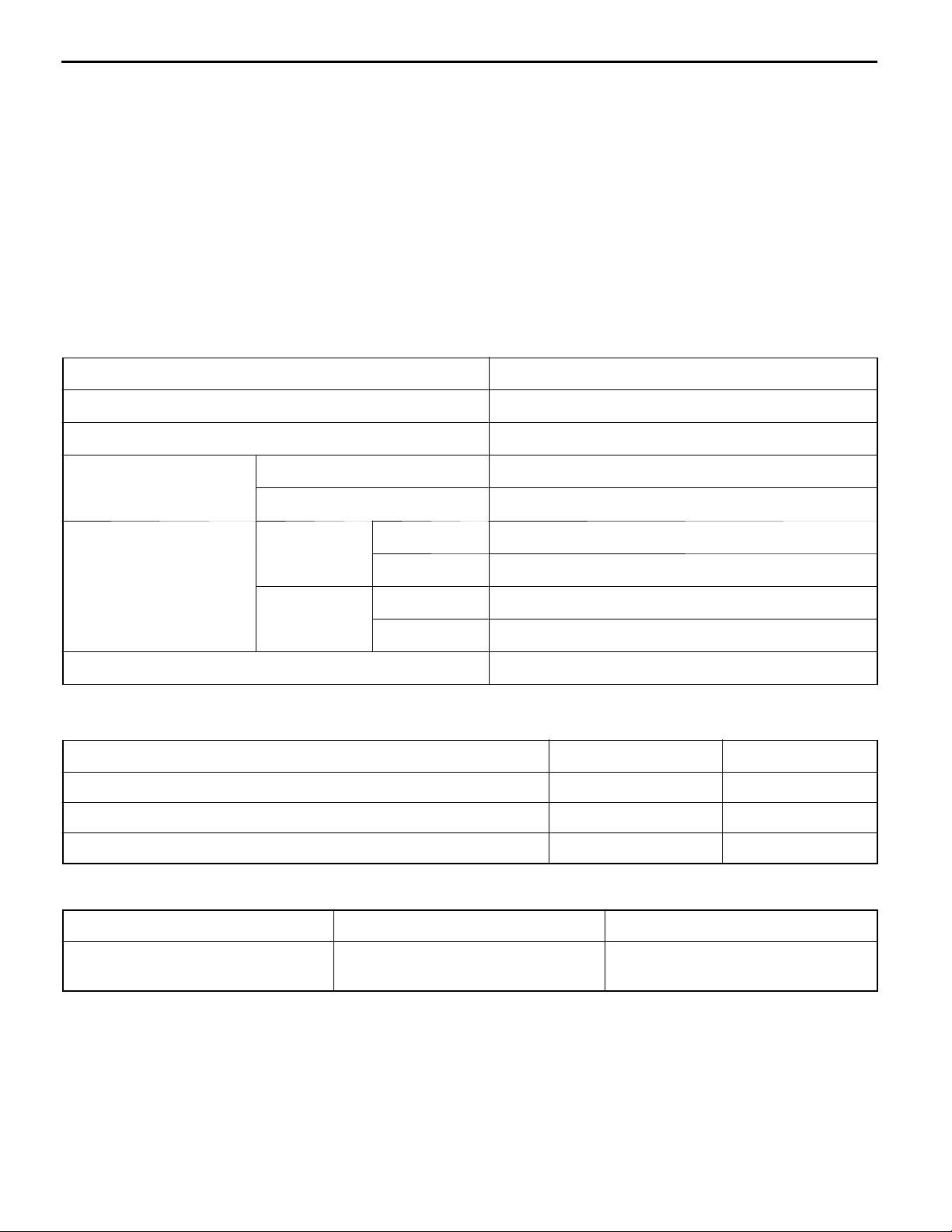
VEHICLE IDENTIFICATION
MODELS
Model code Engine model Transmission model Fuel supply system
CJ1A MNDEL6/R6 4G13 (1,298 mL) F5M41 <5M/T> MPI
(Electronically Controlled
MNJEL6/R6
CJ4A MNJEL6/R6 4G92 MPI (1,597 mL)
MRJEL6/R6 F4A41
<INVECS-II 4A/T>
Multi Point Fuel Injection)
CJ
1
MODEL CODE
A
4
2
M
NJEL
3
5
4
67
6
9
8
No. Items Contents
1 Development CJ: MITSUBISHI (2-door)
2 Engine type 1: 1,298 mL petrol engine
4: 1,597 mL petrol engine
3 Sort A: Passenger car
4 Body style M: 2-door hatchback
5 Transmission type N: 5-speed manual
transmission
R: 4-speed automatic
transmission
6 Trim level D: GL
J: GLX or GLXi
7 Specification engine
feature
8 Steering wheel
location
E: SOHC-MPI
L: Left hand
R: Right hand
9 Destination 6: For Europe
Page 5
GENERAL - Vehicle Identification
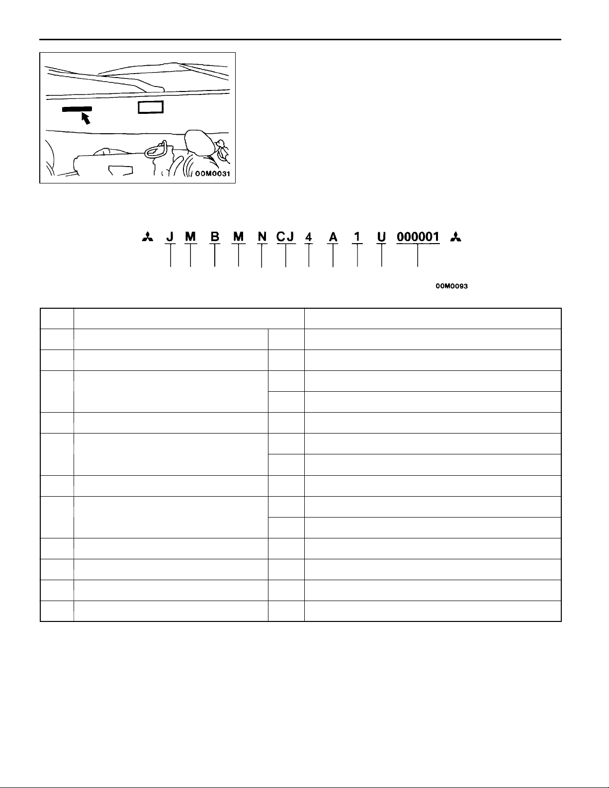
CHASSIS NUMBER
The chassis number is stamped on the toeboard inside the
engine compartment.
00-3
12 3
No. Items Contents
1 Fixed figure J Asia
2 Distribution channel M Japan channel
3 Destination A For Europe, right hand drive
4 Body style M 2-door hatchback
5 Transmission type N 5-speed manual transmission
6 Development order CJ COLT
7 Engine 1 4G13: 1,298 mL petrol engine
8 Sort A Passenger car
5
4
67891110
B For Europe, left hand drive
R 4-speed automatic transmission
4 4G92: 1,597 mL petrol engine
9 Model year 1 2001
10 Plant U Mizushima Motor Vehicle Works
11 Serial number - -
Page 6
00-4
GENERAL - Major Specifications
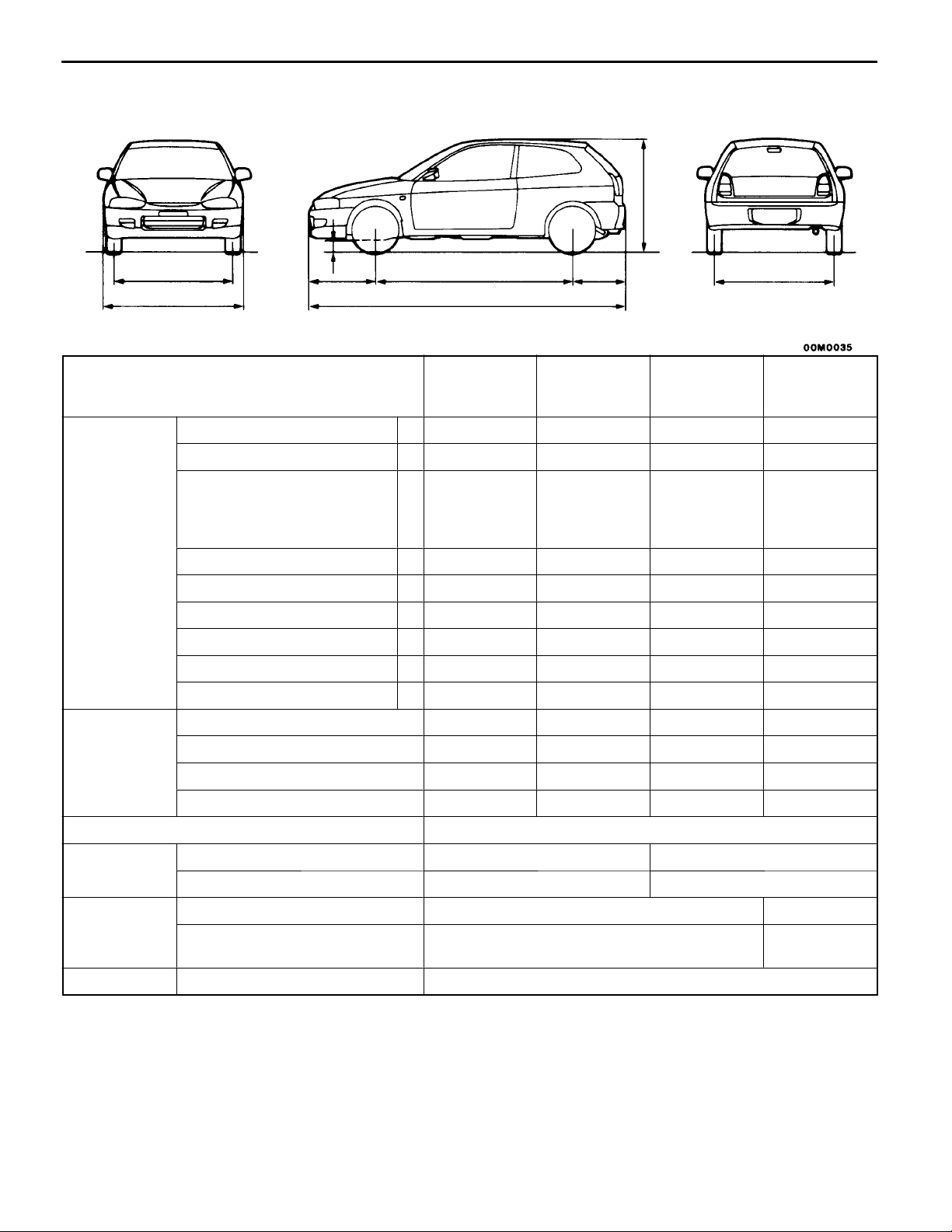
MAJOR SPECIFICATIONS
HATCHBACK
9
5
2
7
3
4
1
86
Items CJ1A
MNDEL6,
MNDER6
Vehicle
dimensions
mm
mm
Overall length 1 3,900 3,900 3,900 3,900
Overall width 2 1,680 1,680 1,680 1,680
Overall height (unladen) 3 1,365,
1,380*
1,385*
1,400*
Wheelbase 4 2,415 2,415 2,415 2,415
Track-front 5 1,450 1,450 1,450 1,450
Track-rear 6 1,460 1,460 1,460 1,460
Overhang-front 7 825 825 825 825
Overhang-rear 8 660 660 660 660
Ground clearance (unladen) 9 150, 165*1,*3150, 165*1,*3150, 165*1,*3150, 165*1,*
Vehicle
weight kg
Kerb weight 950 955 975 995
Max. gross vehicle weight rating 1,445 1,445 1,470 1,480
Max. axle weight rating-front 810 810 810 810
Max. axle weight rating-rear 705 705 705 705
CJ1A
MNJEL6,
MNJER6
1
,
2
,
3
1,365,
1,380*
1,385*
1,400*
1
,
2
,
3
CJ4A
MNJEL6,
MNJER6
1,365,
1
1,380*
1,385*
1,400*
,
2
,
3
CJ4A
MNJEL6,
MNJER6
1,365,
1
1,380*
1,385*
1,400*
,
2
,
3
3
Seating capacity 5
Engine
Model No. 4G13 4G92
Total displacement mL 1,298 1,597
Transmission
Model No. F5M41 F4A41
Type 5 speed-manual 4 speed-
automatic
Fuel system Fuel supply system MPI (Electronically Controlled Multi Point Fuel Injection)
NOTE
1
: indicates vehicles with high ground suspension.
1. *
2
: indicates vehicles with rear spoiler.
2. *
3
3. *
: indicates vehicles with high ground suspension and rear spoiler.
Page 7

ENGINE
CONTENTS
ENGINE <4G1> 11A......................................................
ENGINE <4G9> 11B......................................................
11A-1
Page 8

11A-2
ENGINE <4G1>
CONTENTS
GENERAL 3.................................
Outline of Changes 3..........................
GENERAL INFORMATION 3..................
SERVICE SPECIFICATIONS 3.................
SEALANT 3..................................
SPECIAL TOOLS 4..........................
ON-VEHICLE SERVICE 5.....................
Compression Pressure Check 5.................
Lash Adjuster Check 5.........................
CAMSHAFT AND CAMSHAFT OIL SEAL 8....
CRANKSHAFT FRONT OIL SEAL 11..........
CYLINDER HEAD GASKET 12...............
Page 9
General/General Information/
ENGINE <4G1> -
Service Specifications/Sealant
GENERAL
OUTLINE OF CHANGES
The following service procedures have been
established due to the addition of the 4G13-SOHC
16 valve MPI engine. Furthermore, other items are
the same as for the 4G13-SOHC 12 valve MPI
engine.
D The basic ignition timing has been changed
as a direct-mounted crank angle sensor has
been used.
D The compression pressure has been changed.
D An auto-lash adjuster has been adopted.
D Camshaft and camshaft oil seal removal and
installation
D Crankshaft front oil seal removal and installation
D Cylinder head gasket removal and installation
GENERAL INFORMATION
Items 4G13
Compression ratio 10.0
Combustion chamber Pentroof type
Number of valve Intake 8
11A-3
Exhaust 8
V alve timing Intake Opening BTDC 17
Closing ABDC 39
Exhaust Opening BBDC 49
Closing ATDC 7
Auto-lash adjuster Equipped
_
_
_
_
SERVICE SPECIFICATIONS
Items Standard value Limit
Basic ignition timing 5_BTDC±3
Compression pressure (250 – 400 r/min) kPa 1,598 Min. 1,161
Cylinder head bolt shank length mm - 103.2
_
-
SEALANT
Items Specified sealant Remarks
Camshaft position sensor support MITSUBISHI GENUINE PART
MD970389 or equivalent
Semi-drying sealant
Page 10
11A-4
ENGINE <4G1> -
Special Tools
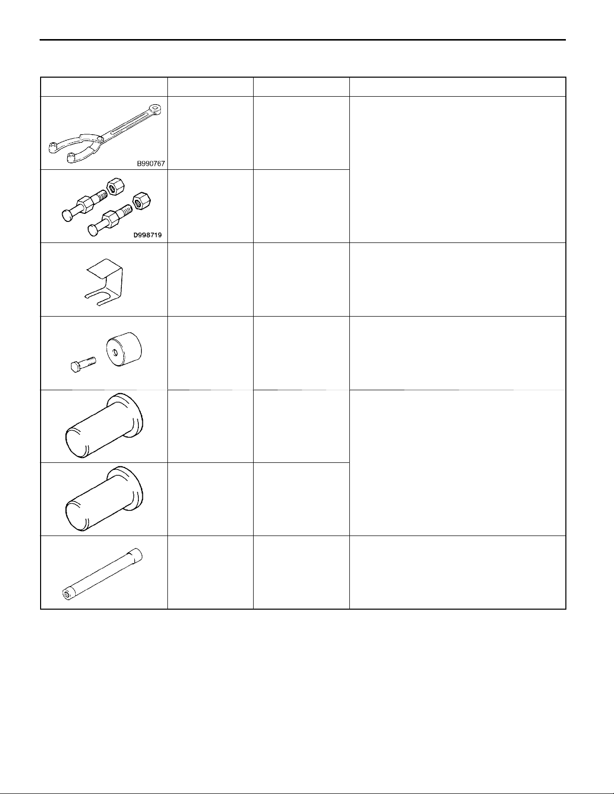
SPECIAL TOOLS
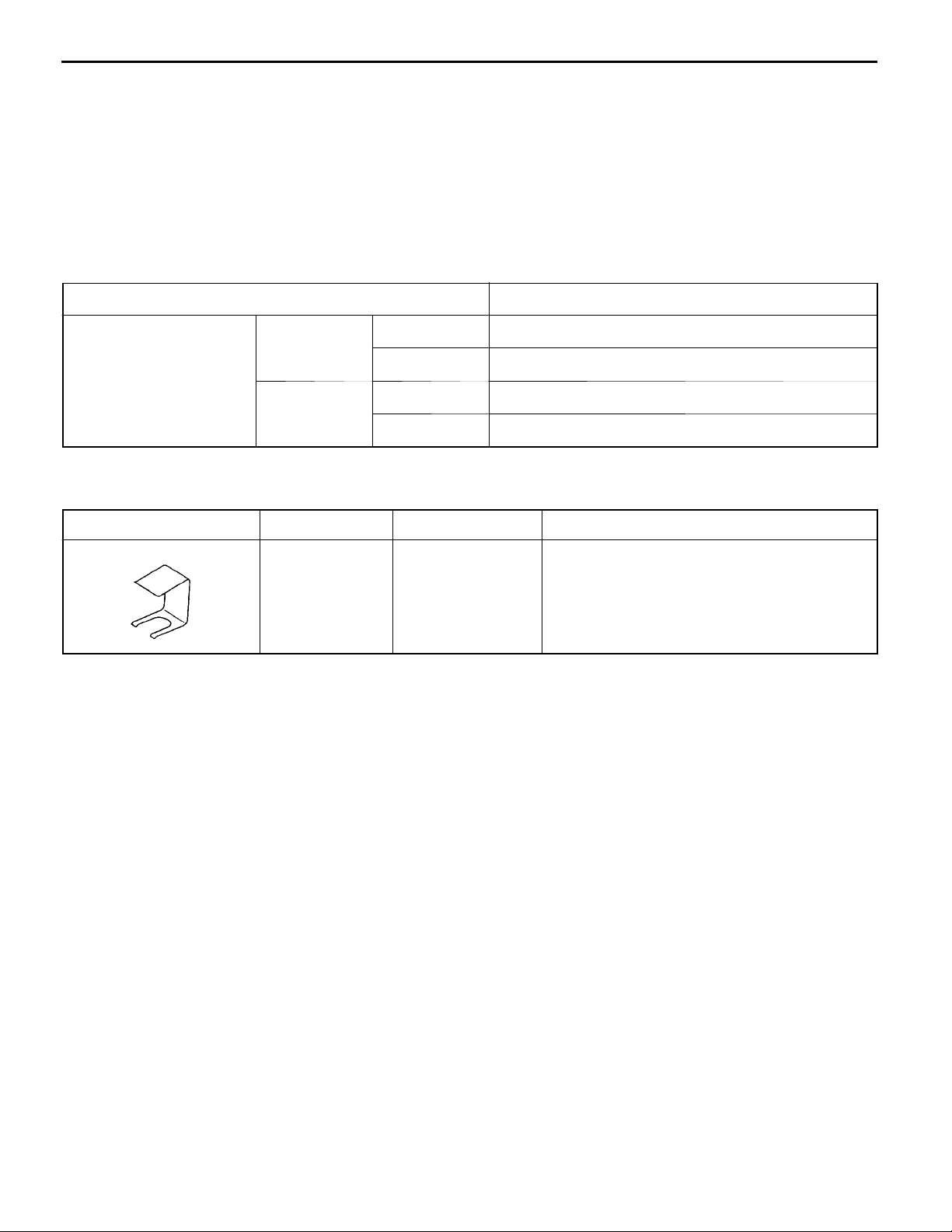
Tool Number Name Use
MB990767 Front hub and
flange yoke holder
MD998719 Crankshaft pulley
holder pin
MD998443 Auto-lash adjuster
holder
MD998713 Camshaft oil seal
installer
Holding the camshaft sprocket
Supporting of lash adjuster
Press-in of the camshaft oil seal
MD998304 Crankshaft front oil
seal installer
MD998305 Crankshaft front oil
seal guide
MB991653 Cylinder head bolt
wrench
Press-fitting the crankshaft front oil seal
Cylinder head bolt removal and installation
Page 11

ENGINE <4G1> -
ON-VEHICLE SERVICE
COMPRESSION PRESSURE CHECK
The disconnection of the distributor connector has been
changed to the disconnection of the crank angle sensor
connector due to the change of the crank angle sensor. Other
service procedures are the same as before.
Standard value (at engine speed of 250 - 400 r/min):
Limit (at engine speed of 250 - 4 00 r/min):
LASH ADJUSTER CHECK
If an abnormal noise (knocking) that seems to be coming
from the lash adjuster is heard after starting the engine and
does not stop, carry out the following check.
NOTE
(1) The abnormal noise which is caused by a problem
(2) If there is a problem with the lash adjusters, the noise
On-vehicle Service
1,598 kPa
Min. 1,161 kPa
with the lash adjusters is generated after the engine
is started, an d will vary according to the engine speed.
However, this noise is not related to the actual engine
load.
Because of this, if the noise does not occur
immediately after the engine is started, if it does not
change in accordance with the engine speed, or if
it changes in accordance with the engine load, the
source of the noise is not the lash adjusters.
will almost never disappear, even if the engine has
been run at idle to let it warm up.
The only case where the noise might disappear is
if the oil in the engine has not been looked after
properly and oil sludge has caused the lash adjusters
to stick.
11A-5
1. Start the engine.
2. Check that the noise occurs immediately after the engine
is started, and that the noise changes in accordance
with changes in the engine speed.
If the noise does not occur immediately after the engine
is started, or if it does not change in accordance with
the engine speed, the problem is not being caused by
the lash adjusters, so check for some other cause of
the problem. Moreover, if the noise does not change in
accordance with the engine speed, the cause of the
problem is probably not with the engine. (In these cases,
the lash adjusters are normal.)
3. While the engine is idling, check that the noise level does
not change when the engine load is varied.
If the noise level changes, the cause of the noise is
probably parts striking because of worn crankshaft
bearings or connecting rod bearings. (In such cases, the
lash adjusters are normal.)
Page 12
11A-6
ENGINE <4G1> -
4. After the engine has warmed up, run it at idle and check
if any noise can be heard.
If the noise has become smaller or disappeared, oil sludge
could make the lash adjusters stick. Clean the lash
adjusters. (Refer to the Engine Workshop Manual.) If not
improved, go to step 5.
5. Bleed air from the lash adjusters.
6. If the noise has not disappeared even after the air
bleeding, clean the lash adjusters. (Refer to the Engine
Workshop Manual.)
<LASH ADJUSTER AIR BLEEDING>
NOTE
(1) If the vehicle is parked on a slope for a long period
(2) After parking the vehicle for long periods, the oil drains
(3) If either of the above situations occur, the abnormal
On-vehicle Service
of time, the amount of oil inside the lash adjuster
will decrease, and air may get into the high pressure
chamber when starting the engine.
out of the oil passage, and it takes time for the oil
to be supplied to th e lash adjuster, so air can get
into the high pressure chamber.
noise can be eliminated by bleeding the air from inside
the lash adjusters.
Good
Highpressure
chamber
1. Check the engine oil and replenish or replace the oil
if necessary.
NOTE
(1) If there is a only small amount of oil, air will be drawn
in through the oil screen and will get into the oil
passage.
(2) If the amount of oil is greater than normal, then the
oil will being mixed by the crankshaft and a large
amount of air may get mixed into the oil.
(3) If the oil is degenerated, air and oil will not separate
easily in oil, and the amount of air mixed into the
oil will increase.
(4) If the air which has been mixed in with the oil due
to any of the above reasons gets into the high pressure
chamber of the lash adjuster, the air inside the high
pressure chamber will be compressed when the valve
is open and the lash adjuster will over-compress,
resulting in abnormal noise when the valve closes.
This is the same effect as if the valve clearance is
adjusted to be too large by mistake. If the air inside
the lash adjusters is then released, the operation
of the lash adjusters will return to normal.
Page 13
ENGINE <4G1> -
On-vehicle Service
11A-7
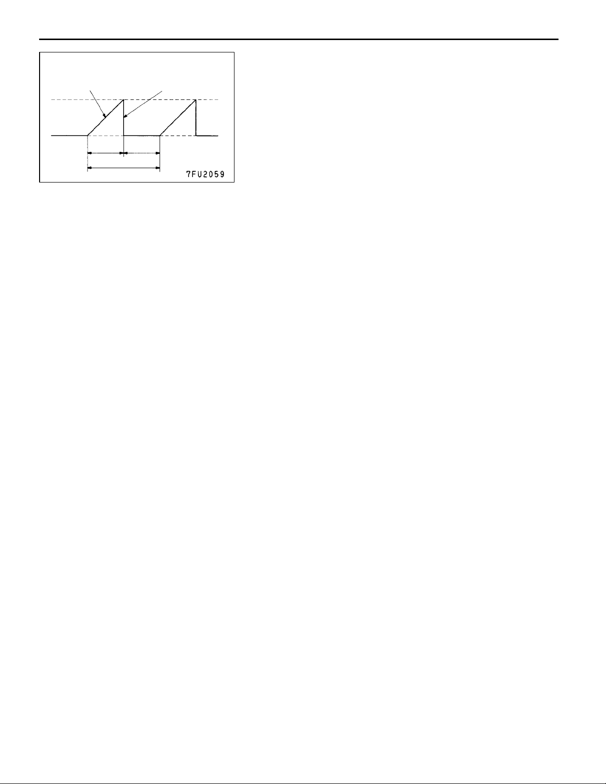
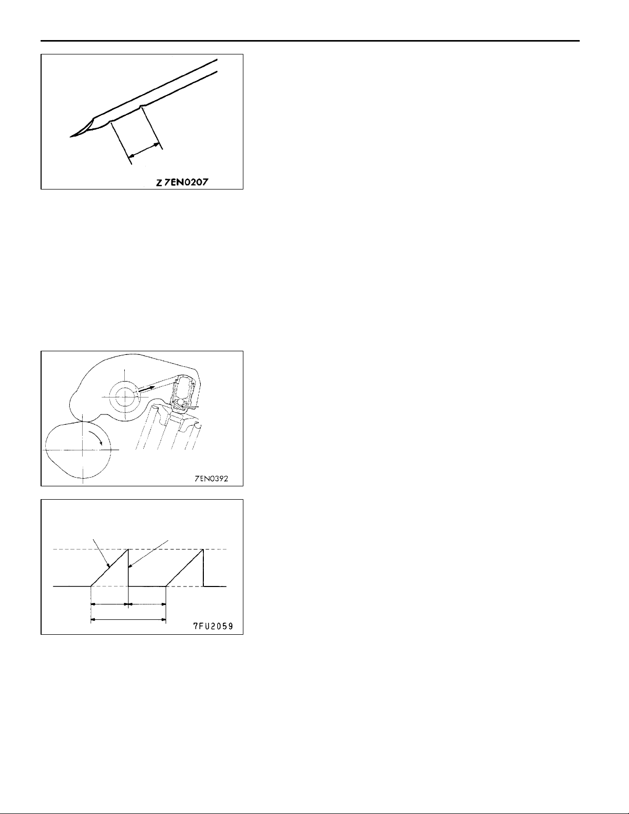
Drive pattern for air bleeding
Gradually open the
throttle valve.
Approx.
3,000 r/min
Idle speed
15
seconds
Once
Close the throttle
valve.
15
seconds
2. Run the engine at idle for 1 - 3 minutes to let it warm
up.
3. With no load on the engine, repeat the drive pattern shown
in the illustration at left and check if the abnormal noise
disappears. (The noise should normally disappear after
10 - 30 repetitions, but if there is no change in the noise
level after 30 repetitions or more, the problem is probably
not due to air inside the lash adjusters.)
4. After the noise has disappeared, repeat the drive pattern
shown in the illustration at left a further 5 times.
5. Run the engine at idle for 1 - 3 minutes and check that
the noise has disappeared.
Page 14
11A-8
ENGINE <4G1> - Camshaft and Camshaft Oil Seal
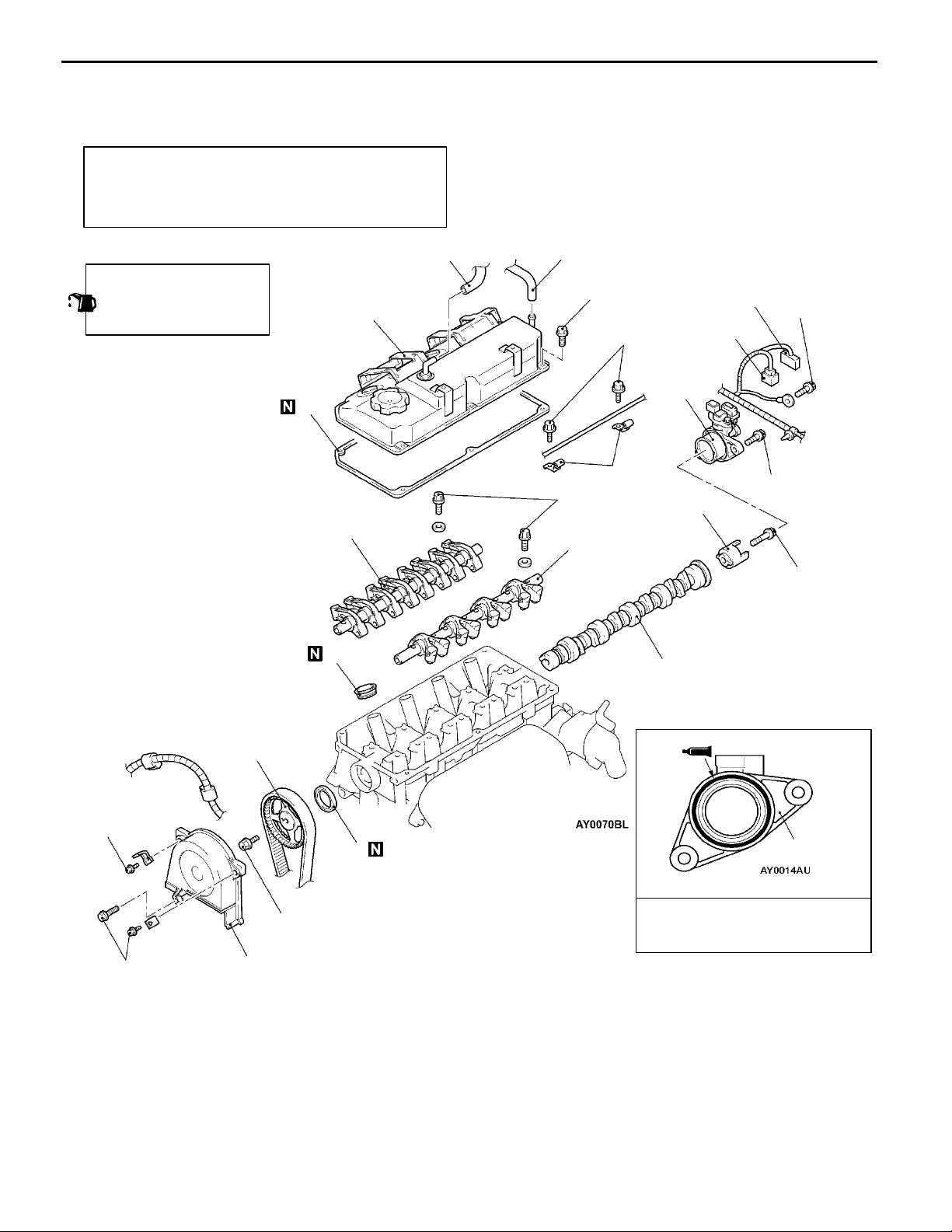
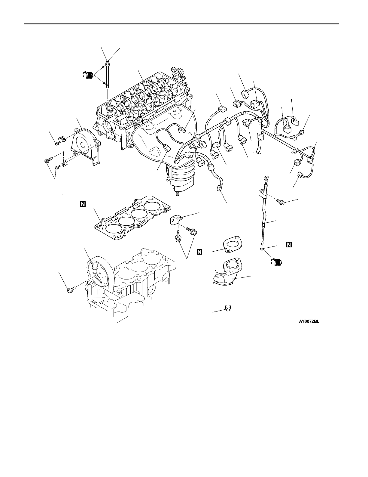
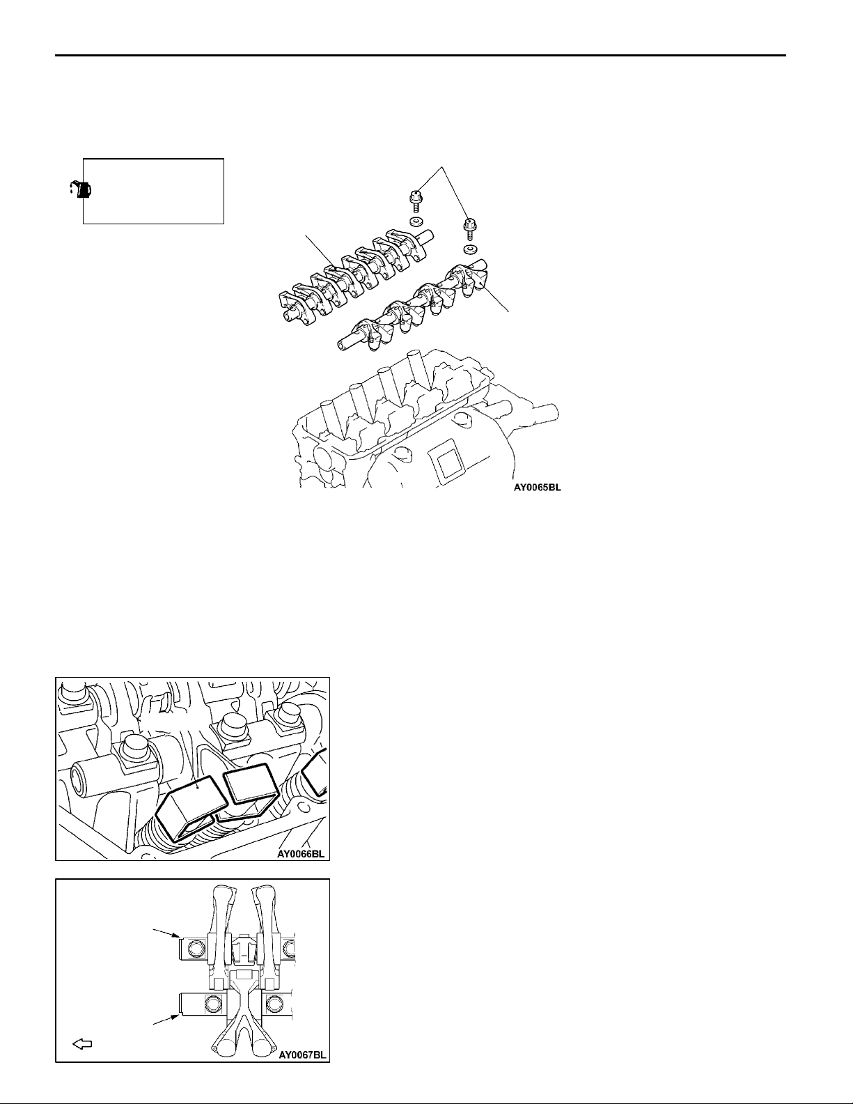
CAMSHAFT AND CAMSHAFT OIL SEAL
REMOVAL AND INSTALLATION
Pre-removal and Post-installation Operation
D Air Cleaner Removal and Installation
D Ignition Coil Removal and Installation
(Refer to GROUP16.)
12
Apply engine oil to all
moving parts during
installation.
3.5 Nm
4
10 - 12 Nm
13
12
5.0 Nm
14
5
3
28 - 34 Nm
10
11
6
16
15
12 - 15 Nm
22 Nm
10 - 12 Nm
10 - 12 Nm
AA""CA
"BA
8
9
88 Nm
7
Removal steps
1. Breather hose connection
2. PCV hose connection
3. Accelerator cable clamp
<LH drive vehicles>
4. Rocker cover
5. Rocker cover gasket
6. Spark plug guide
7. Timing belt front upper cover
8. Camshaft sprocket
9. Camshaft oil seal
AB""AA
AB""AA
14
Sealant:
MITSUBISHI GENUINE PART
MD970389 or equivalent
10. Lash adjuster, intake rocker arm
and shaft assembly
11. Lash adjuster, exhaust rocker arm
and shaft assembly
12. Ignition failure sensor connector
13. Camshaft position sensor connector
14. Camshaft position sensor support
15. Camshaft
16. Camshaft position sensing cylinder
Page 15
ENGINE <4G1> - Camshaft and Camshaft Oil Seal
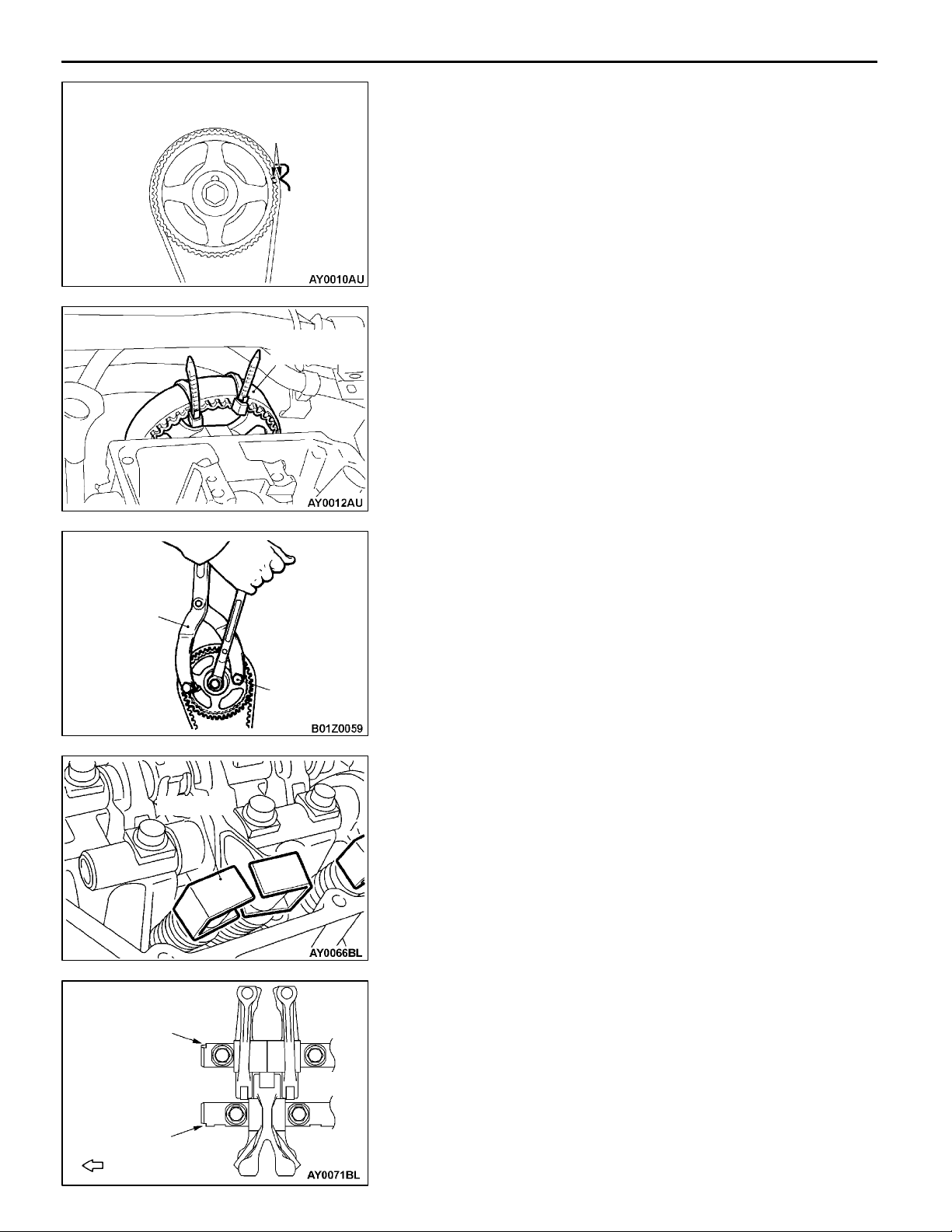
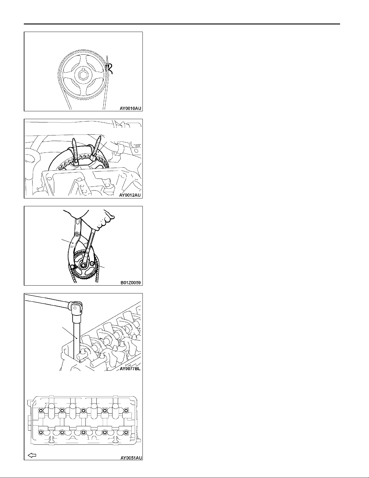
REMOVAL SERVICE POINTS
Timing mark
Camshaft
sprocket
AA"
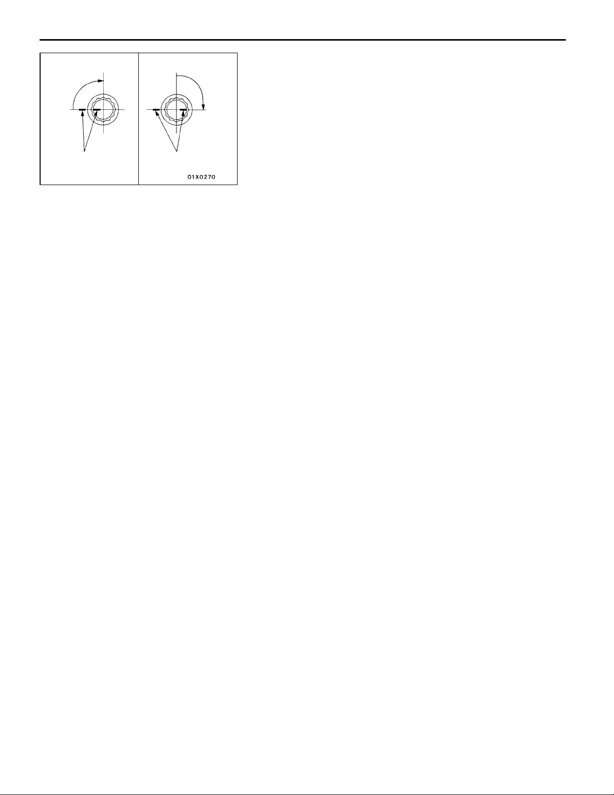
1. Turn the crankshaft in the forward direction (clockwise)
2. Secure the camshaft sprocket and the timing belt with
CAMSHAFT SPROCKET REMOVAL
to align the timing mark so that No.1 cylinder is at the
compression TDC.
Caution
Always turn the crankshaft in the forward direction
(clockwise).
band cables to prevent deviation from the relative positions
between the camshaft sprocket and the timing belt.
11A-9
MB990767
MD998443
MD998719
3. Use the special tool to stop the camshaft sprocket from
turning.
4. Remove the camshaft sprocket with the timing belt
attached.
Caution
Do not turn the crankshaft after the camshaft sprocket
is removed.
AB"
LASH ADJUSTER, INTAKE ROCKER ARM AND
SHAFT ASSEMBLY/LASH ADJUSTER, EXHAUST
ROCKER ARM AND SHAFT ASSEMBLY
REMOVAL
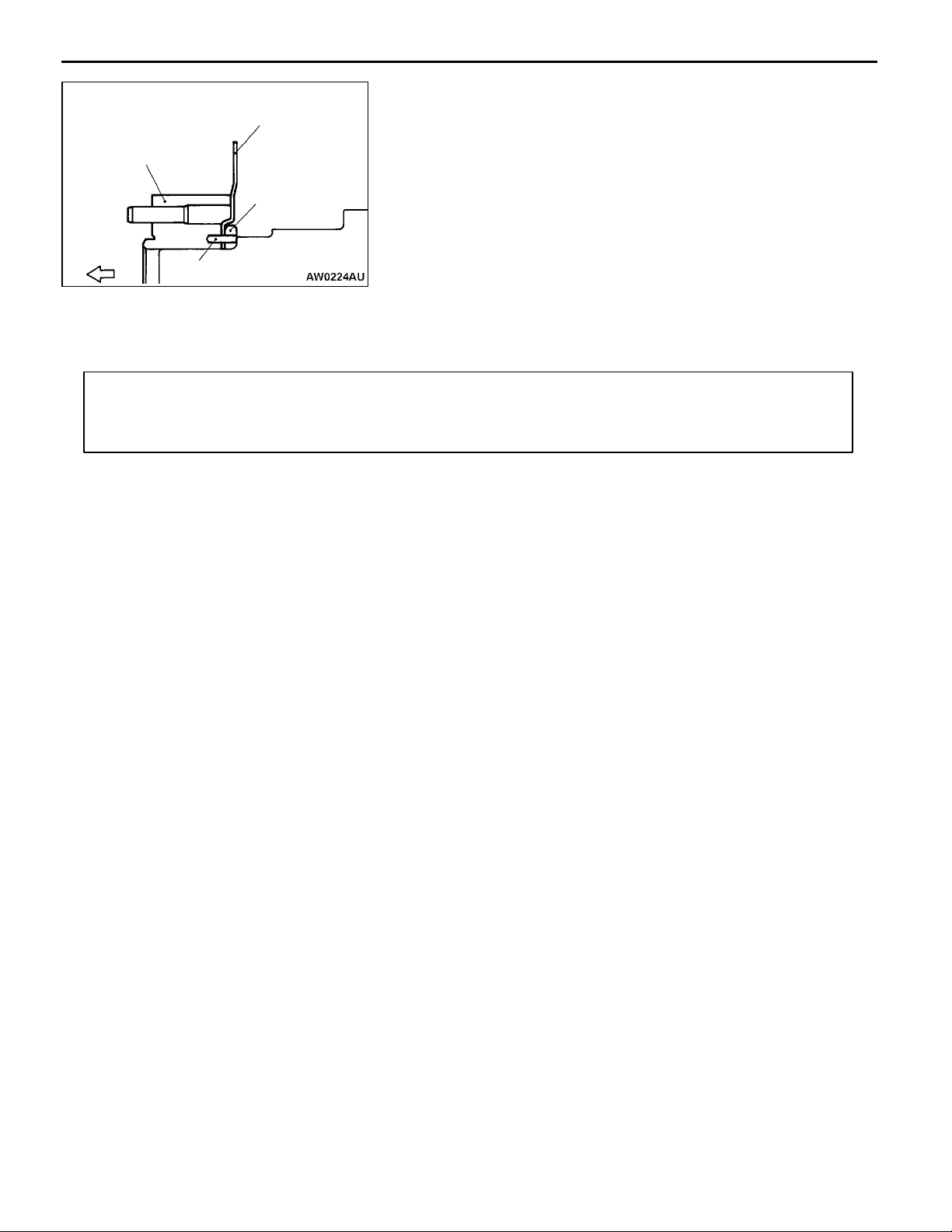
Before removing the lash adjuster, rocker arm a nd shaft
assembly, install the special tools as shown in the illustration
so that the lash adjusters will not fall out.
Notch
Notch
Front of engine
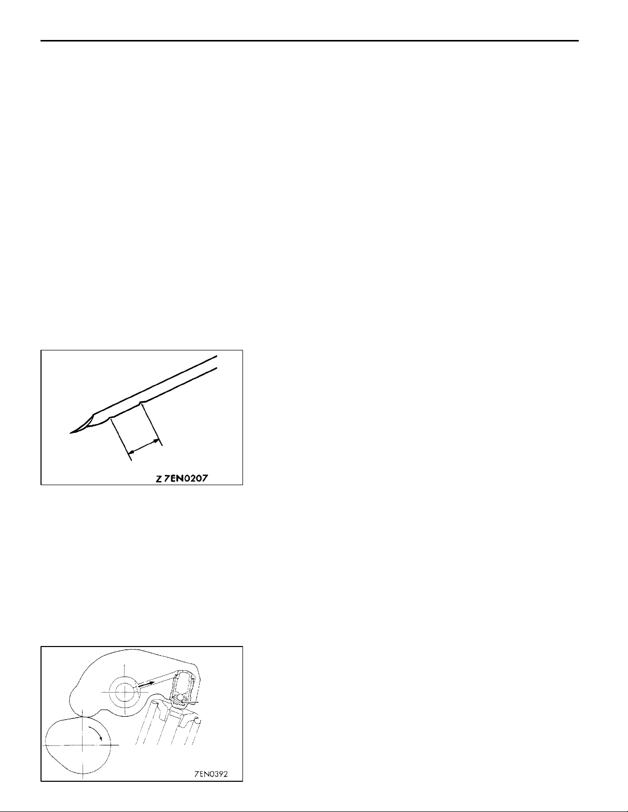
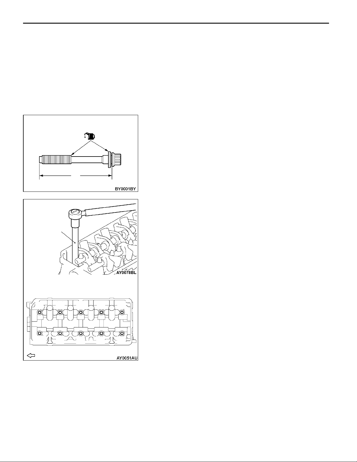
INSTALLATION SERVICE POINTS
"AA
Position the rocker arm shaft so that their notches point the
direction shown, an d install the lash adjuster, rocker arm
and shaft assembly.
LASH ADJUSTER, EXHAUST ROCKER ARM AND
SHAFT ASSEMBLY/LASH ADJUSTER, INTAKE
ROCKER ARM AND SHAFT ASSEMBLY
INSTALLATION
Page 16
11A-10
ENGINE <4G1> - Camshaft and Camshaft Oil Seal
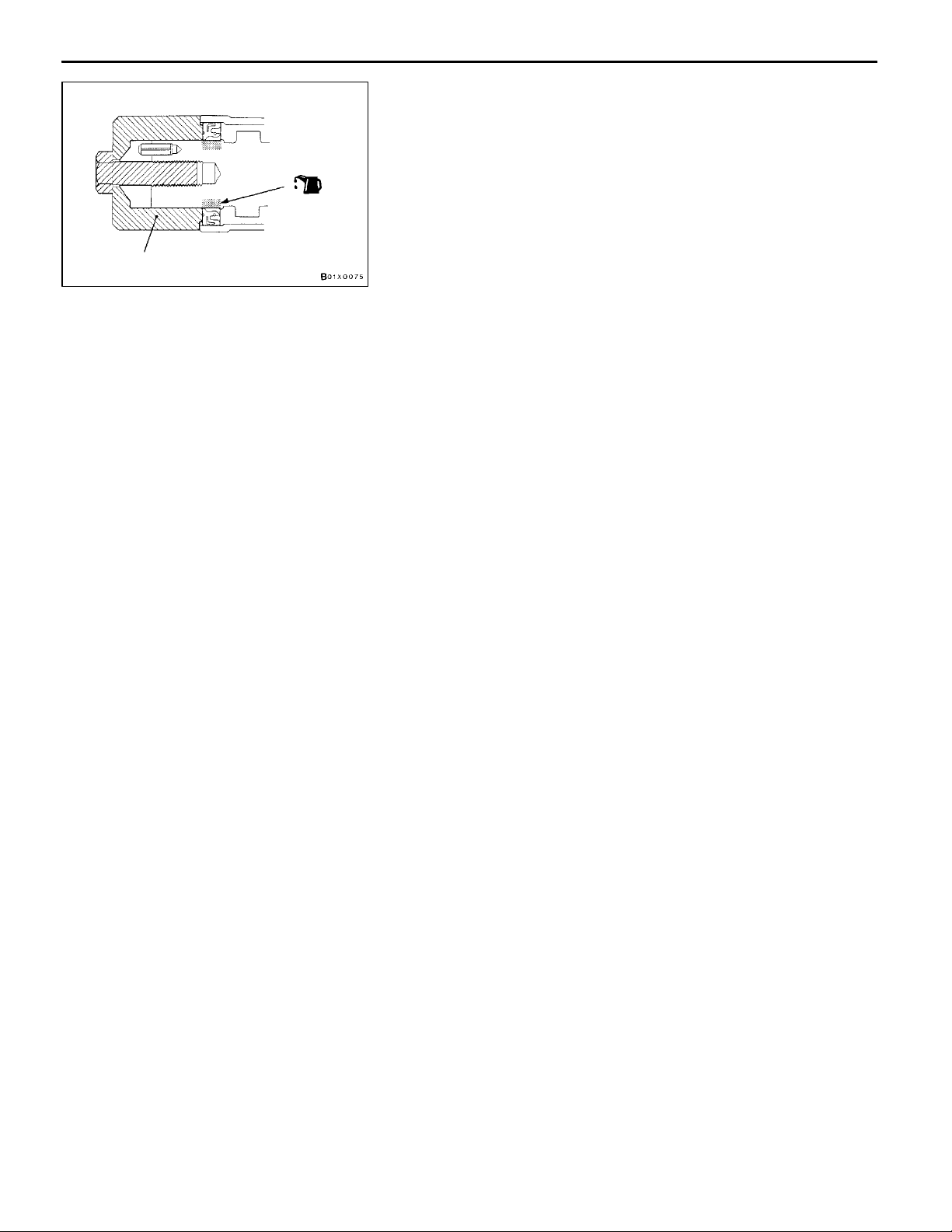
MD998713
"BA
1. Apply engine oil to the camshaft oil seal lip.
2. Use the special tool to press-fit the camshaft oil seal.
"CA
Use the special tool to stop the camshaft sprocket from turning
in the same way as was done during removal, and then tighten
the bolts to the specified torque.
Tightening torque: 88 Nm
CAMSHAFT OIL SEAL INSTALLATION
CAMSHAFT SPROCKET INSTALLATION
Page 17
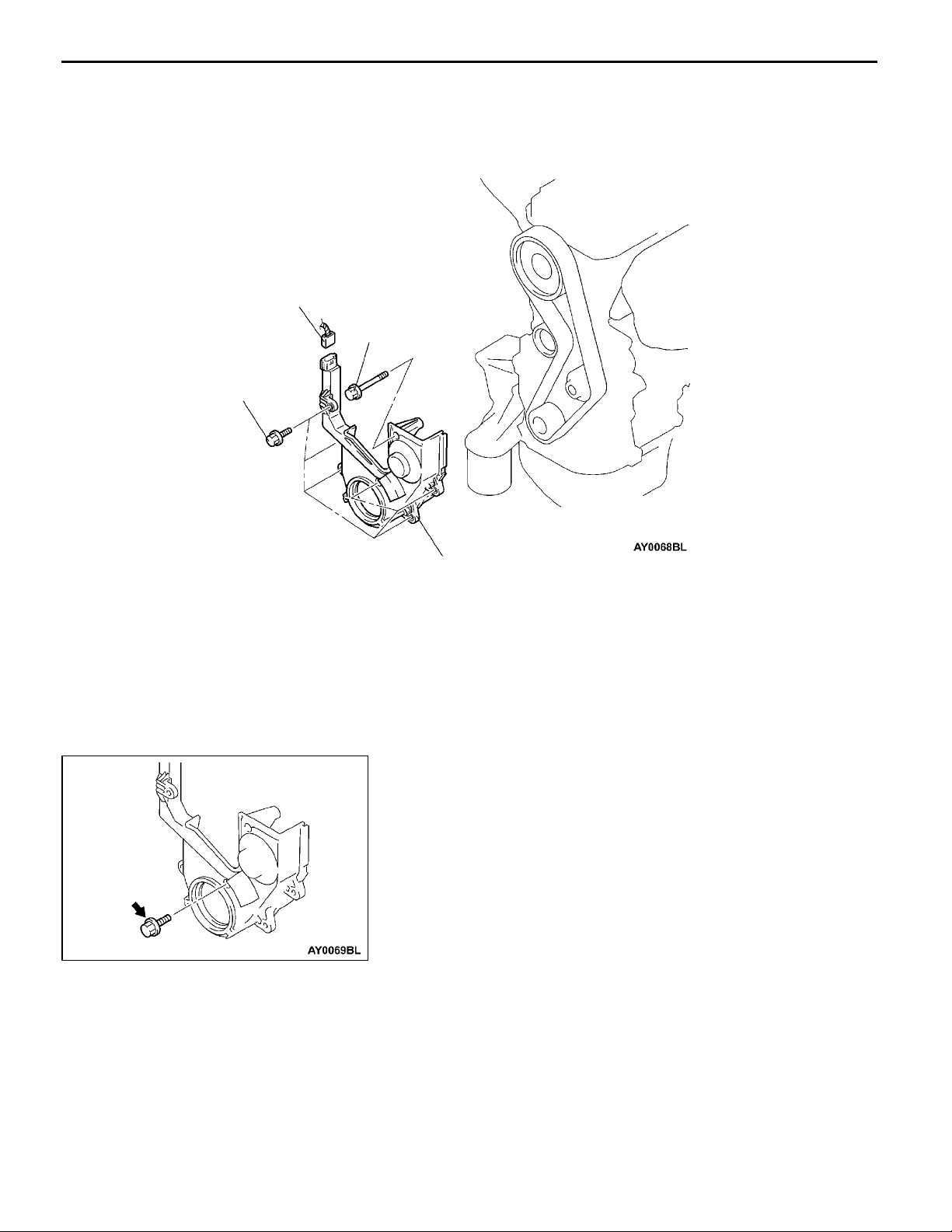
ENGINE <4G1> - Crankshaft Front Oil Seal
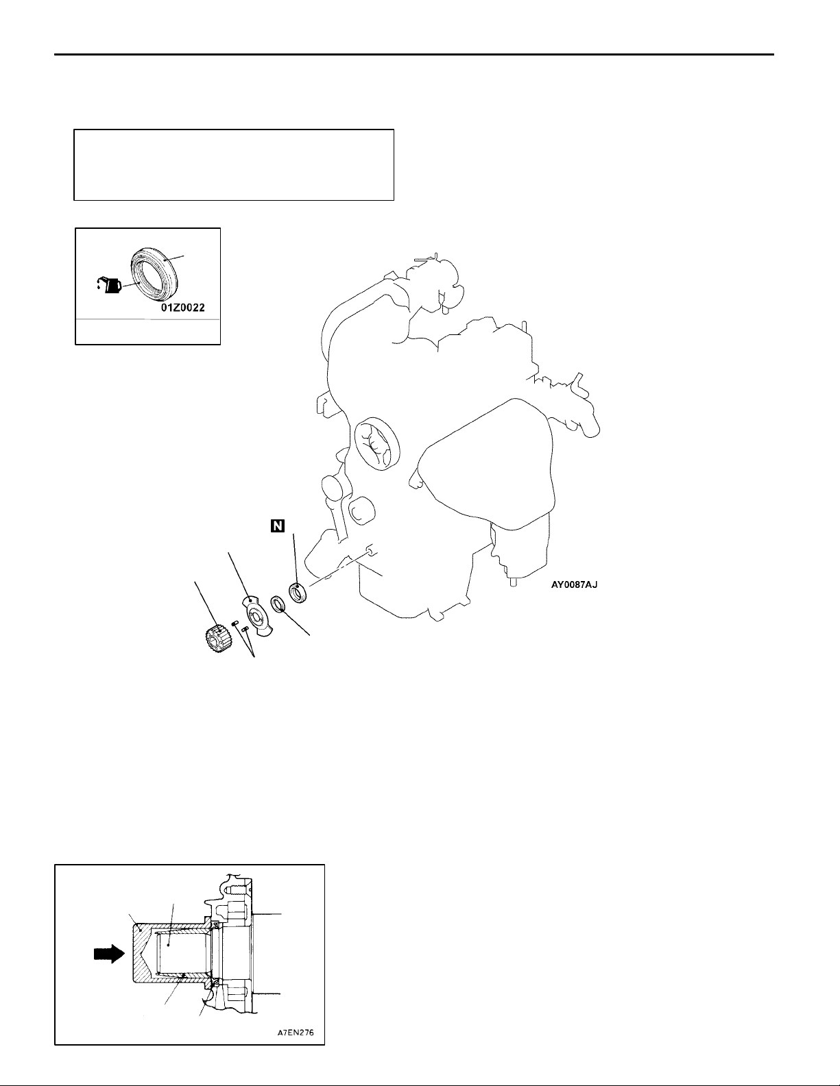
CRANKSHAFT FRONT OIL SEAL
REMOVAL AND INSTALLATION
Pre-removal and Post-installation Operation
D Timing Belt Removal and Installation
D Crank angle sensor Removal and Installation
(Refer to GROUP16.)
5
(Lip)
Engine oil
11A-11
"BA
"BA
"BA
MD998304
5
3
1
2
Removal steps
1. Crankshaft sprocket
2. Spring pin
3. Crankshaft sensing blade
Crankshaft
4
"BA
"AA
4. Crankshaft spacer
5. Crankshaft front oil seal
INSTALLATION SERVICE POINTS
"AA
1. Apply a small amount of engine oil to the entire
2. Tap the oil seal unit it flushes with the oil seal case.
CRANKSHAFT FRONT OIL SEAL INSTALLATION
circumference of the oil seal lip.
MD998305
Oil seal
Page 18
11A-12
ENGINE <4G1> - Crankshaft Front Oil Seal/Cylinder Head Gasket
Crankshaft
sensing blade
Crankshaft
sprocket
Crankshaft
spacer
Front of
engine
Spring pin
CYLINDER HEAD GASKET
REMOVAL AND INSTALLATION
Pre-removal and Post-installation Operation
Prevention of Fuel Discharge <before removal only>
D
Fuel Leak Check <after installation only>
D
Under Cover Removal and Installation
D
"BA
CRANKSHAFT SPACER/CRANKSHAFT SENSING
BLADE/SPRING PIN/CRANKSHAFT SPROCKET
INSTALLATION
Install t he crankshaft sprocket assembled with the spring pin,
the crankshaft sensing blade, and the crankshaft spacer to
the crankshaft.
Engine Coolant Draining and Supplying
D
Engine Oil Draining and Supplying
D
Air Cleaner Removal an d Installation
D
Page 19
ENGINE <4G1> - Cylinder Head Gasket
11A-13
(Engine oil)
10 - 12 Nm
10 - 12 Nm
21
25
23
49 Nm®0Nm®20 Nm®+90°®+90°(Cold engine)
24
8
9
10
4
2
5
6
7
3
1
18
14
15
5.0 Nm
12
13
11
24 Nm
19
88 Nm
22
Removal steps
1. Crank angle sensor connector
2. Detonation sensor connector
3. Oxygen sensor (rear) connector
4. Vacuum sensor connector
5. Ignition coil connector
6. Injector connector
7. EGR solenoid valve connector
8. Throttle position sensor connector
9. Idle speed control servo connector
10. Purge control solenoid valve
connector
11. Engine coolant temperature gauge
unit connector
12. Oxygen sensor (front) connector
13. Engine coolant temperature sensor
connector
35 Nm
50 Nm
AA""CA
AB""BA
17
"AA
20
(Engine oil)
16
14. Ignition failure sensor connector
15. Camshaft position sensor connector
D
Rocker cover (Refer to P.11A-8.)
D
Intake manifold
(Refer to GROUP 15.)
D
Water inlet pipe (Refer to GROUP 14.)
16. Front exhaust pipe connection
17. Front exhaust pipe gasket
18. Exhaust manifold bracket
19. Oil level gauge assembly
20. O-ring
21. Timing belt front upper cover
22. Camshaft sprocket
23. Cylinder head bolts
24. Cylinder head assembly
25. Cylinder head gasket
Page 20
11A-14
ENGINE <4G1> - Cylinder Head Gasket
REMOVAL SERVICE POINTS
Timing mark
Camshaft
sprocket
AA"
1. Turn the crankshaft in the forward direction (clockwise)
2. Secure the camshaft sprocket and the timing belt with
CAMSHAFT SPROCKET REMOVAL
to align the timing mark so that No.1 cylinder is at the
compression TDC.
Caution
Always turn the crankshaft in the forward direction
(clockwise).
band cables to prevent deviation from the relative positions
between the camshaft sprocket and the timing belt.
MB990767
MB991653
MD998719
3. Use the special tool to stop the camshaft sprocket from
turning.
4. Remove the camshaft sprocket with the timing belt
attached.
Caution
Do not turn the crankshaft after the camshaft sprocket
is removed.
AB"
CYLINDER HEAD BOLT REMOVAL
Use the special tool to loosen the bolts in 2 or 3 steps in
order of the numbers shown in the illustration, a nd remove
the cylinder head assembly.
3
1
Front of engine
5
7
10
9
8
6
2
4
Page 21
ENGINE <4G1> - Cylinder Head Gasket
INSTALLATION SERVICE POINTS
"AA
1. Wipe off all oil and grease from the gasket mounting
2. Install so that the shapes of the cylinder head holes match
CYLINDER HEAD GASKET INSTALLATION
surface.
Caution
Do not allow foreign material to enter the engine
coolant or oil passages and the cylinder.
the shapes of the respective cylinder head gasket holes.
11A-15
(Engine oil)
MB991653
"BA
CYLINDER HEAD BOLT INSTALLATION
1. When installing the cylinder head bolts, the length below
the head of the bolts should be within the limit.
If it is outside the limit, replace the bolts.
Limit (A): 103.2 mm
2. Apply a small amount of engine oil to the thread section
and the washer of the cylinder head bolt.
A
3. Use the special tool to tighten the bolts by the following
procedure (angle-tightening procedure).
(1) Tighten the cylinder head bolts in the shown sequence
to 49 Nm.
(2) Loosen the cylinder head bolts completely in the
reverse of the shown sequence.
(3) Tighten the cylinder head bolts in the shown order
to 20 Nm.
8
10
Front of engine
6
4
1
2
3
5
9
7
Page 22
11A-16
ENGINE <4G1> - Cylinder Head Gasket
Step (4)
90
Painted mark
Step (5)
_
90
_
(4) Mark the cylinder head bolts and the cylinder head with
paint, and then tighten the bolts in the shown
sequence to 90°.
(5) Tighten the bolts in the shown sequence to additional
90°, and check that the paint marks on the cylinder
head bolts are flush with the paint marks on the
cylinder head.
Caution
Painted mark
1) If the tightening angle is less than 90°, the
bolt is loose.
2) If the tightening angle is more than 90°, loosen
the bolt and repeat the procedure from step
1.
"CA
CAMSHAFT SPROCKET INSTALLATION
Use the special tool to stop the camshaft sprocket from turning
in the same way as was done during removal, and then tighten
the bolts to the specified torque.
Tightening torque: 88 Nm
Page 23

ENGINE <4G9>
CONTENTS
11B-1
GENERAL 2.................................
Outline of Changes 2..........................
GENERAL INFORMATION 2..................
SPECIAL TOOL 2............................
ON-VEHICLE SERVICE 2.....................
Ignition Timing Check 2........................
Lash Adjuster Check 2.........................
CAMSHAFT AND CAMSHAFT OIL SEAL 5....
TIMING BELT 6..............................
Page 24
11B-2
ENGINE <4G9> -
General/General Information/
Special Tool/On-vehicle Service
GENERAL
OUTLINE OF CHANGES
The following service procedures have been
changed. Furthermore, other items are the same
as before.
D The valve timing has been changed.
D The ignition timing has been changed.
D An auto-lash adjuster has been added.
D The timing belt lower cover has been changed.
GENERAL INFORMATION
Items 4G9
V alve timing Intake Opening BTDC 12
Closing ABDC 46
Exhaust Opening BBDC 46
Closing ATDC 2
SPECIAL TOOL
Tool Number Name Use
MD998443 Auto-lash adjuster
holder
ON-VEHICLE SERVICE
_
_
_
_
Supporting of lash adjuster
IGNITION TIMING CHECK
The ignition timing has been changed. Other service
procedures are the same as before.
Standard value: Approx. 8_BTDC
LASH ADJUSTER CHECK
If an abnormal noise (knocking) that seems to be coming
from the lash adjuster is heard after starting the engine and
does not stop, carry out the following check.
NOTE
(1) The abnormal noise which is caused by a problem
with the lash adjusters is generated after the engine
is started, an d will vary according to the engine speed.
However, this noise is not related to the actual engine
load.
Page 25

ENGINE <4G9> -
(2) If there is a problem with the lash adjusters, the noise
1. Start the engine.
2. Check that the noise occurs immediately after the engine
is started, and that the noise changes in accordance
with changes in the engine speed.
If the noise does not occur immediately after the engine
is started, or if it does not change in accordance with
the engine speed, the problem is not being caused by
the lash adjusters, so check for some other cause of
the problem. Moreover, if the noise does not change in
accordance with the engine speed, the cause of the
problem is probably not with the engine. (In these cases,
the lash adjusters are normal.)
3. While the engine is idling, check that the noise level does
not change when the engine load is varied (for example,
by shifting from N ® D).
If the noise level changes, the cause of the noise is
probably parts striking because of worn crankshaft
bearings or connecting rod bearings. (In such cases, the
lash adjusters are normal.)
4. After the engine has warmed up, run it at idle and check
if any noise can be heard.
If the noise has become smaller or disappeared, oil sludge
could make the lash adjusters stick. Clean the lash
adjusters. (Refer to the Engine Workshop Manual.) If not
improved, go to step 5.
5. Bleed air from the lash adjusters.
6. If the noise has not disappeared even after the air
bleeding, clean the lash adjusters. (Refer to the Engine
Workshop Manual.)
On-vehicle Service
Because of this, if the noise does not occur
immediately after the engine is started, if it does not
change in accordance with the engine speed, or if
it changes in accordance with the engine load, the
source of the noise is not the lash adjusters.
will almost never disappear, even if the engine has
been run at idle to let it warm up.
The only case where the noise might disappear is
if the oil in the engine has not been looked after
properly and oil sludge has caused the lash adjusters
to stick.
11B-3
<LASH ADJUSTER AIR BLEEDING>
NOTE
(1) If the vehicle is parked on a slope for a long period
of time, the amount of oil inside the lash adjuster
will decrease, and air may get into the high pressure
chamber when starting the engine.
(2) After parking the vehicle for long periods, the oil drains
out of the oil passage, and it takes time for the oil
to be supplied to th e lash adjuster, so air can get
into the high pressure chamber.
(3) If either of the above situations occur, the abnormal
noise can be eliminated by bleeding the air from inside
the lash adjusters.
Page 26
11B-4
Good
ENGINE <4G9> -
1. Check the engine oil and replenish or replace the oil
if necessary.
NOTE
(1) If there is a only small amount of oil, air will be drawn
(2) If the amount of oil is greater than normal, then the
(3) If the oil is degenerated, air and oil will not separate
On-vehicle Service
in through the oil screen and will get into the oil
passage.
oil will being mixed by the crankshaft and a large
amount of air may get mixed into the oil.
easily in oil, and the amount of air mixed into the
oil will increase.
Drive pattern for air bleeding
Gradually open the
throttle valve.
Approx.
3,000 r/min
Idle speed
15
seconds
Once
Close the throttle
valve.
15
seconds
Highpressure
chamber
(4) If the air which has been mixed in with the oil due
to any of the above reasons gets into the high pressure
chamber of the lash adjuster, the air inside the high
pressure chamber will be compressed when the valve
is open and the lash adjuster will over-compress,
resulting in abnormal noise when the valve closes.
This is the same effect as if the valve clearance is
adjusted to be too large by mistake. If the air inside
the lash adjusters is then released, the operation
of the lash adjusters will return to normal.
2. Run the engine at idle for 1 - 3 minutes to let it warm
up.
3. With no load on the engine, repeat the drive pattern shown
in the illustration at left and check if the abnormal noise
disappears. (The noise should normally disappear after
10 - 30 repetitions, but if there is no change in the noise
level after 30 repetitions or more, the problem is probably
not due to air inside the lash adjusters.)
4. After the noise has disappeared, repeat the drive pattern
shown in the illustration at left a further 5 times.
5. Run the engine at idle for 1 - 3 minutes and check that
the noise has disappeared.
Page 27
ENGINE <4G9> - Camshaft and Camshaft Oil Seal
CAMSHAFT AND CAMSHAFT OIL SEAL
REMOVAL AND INSTALLATION
28 - 34 Nm
Apply engine oil to all
sliding parts during
installation.
1
11B-5
2
AA""AA
AA""AA
Notch
Notch
Front of engine
Removal steps
1. Lash adjuster, intake rocker arm
and shaft assembly
2. Lash adjuster, exhaust rocker arm
and shaft assembly
MD998443
REMOVAL SERVICE POINT
AA"
Before removing the lash adjuster, rocker arm a nd shaft
assembly, install the special tools as shown in the illustration
so that the lash adjusters will not fall out.
LASH ADJUSTER, INTAKE ROCKER ARM AND
SHAFT ASSEMBLY/LASH ADJUSTER, EXHAUST
ROCKER ARM AND SHAFT ASSEMBLY
REMOVAL
INSTALLATION SERVICE POINT
"AA
Position the rocker arm shafts so that their notches point
the direction shown, and install the lash adjuster, rocker arm
and shaft assembly.
LASH ADJUSTER, EXHAUST ROCKER ARM AND
SHAFT ASSEMBLY/LASH ADJUSTER, INTAKE
ROCKER ARM AND SHAFT ASSEMBLY
INSTALLATION
Page 28
11B-6
ENGINE <4G9> - Timing Belt
TIMING BELT
REMOVAL AND INSTALLATION
1
10 Nm
10 Nm
Removal steps
1. Crank angle sensor connector
"AA 2. Timing belt lower cover
2
INSTALLATION SERVICE POINT
"AA
1. Mount the bolt shown in the illustration (M6´20 mm)
2. Mount the other bolts, and tighten them to the specified
TIMING BELT LOWER COVER INSTALLATION
first.
torque.
Tightening torque: 10 Nm
Page 29
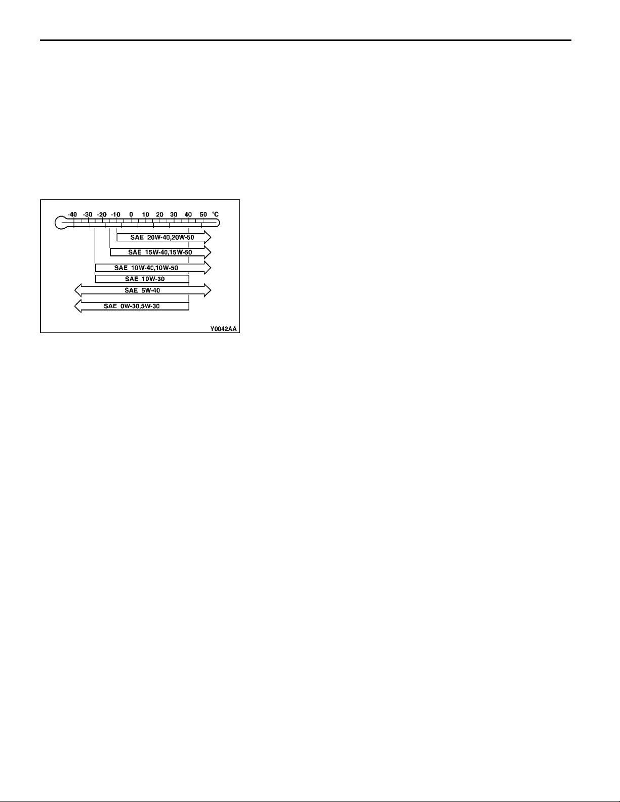
ENGINE LUBRICATION -
GROUP 12
ENGINE LUBRICATION
GENERAL
OUTLINE OF CHANGE
A quality of the engine oil has been changed.
ON-VEHICLE SERVICE
Specified Engine Oil (ACEA and API classification):
General/On-vehicle Service
ACEA A1, A2, A3/API SG or higher
12-1
Page 30

NOTES
Page 31

13A-1
MULTIPOINT FUEL
INJECTION (MPI)
CONTENTS
MULTIPOINT FUEL INJECTION (MPI)
<4G1> 2..............................
GENERAL 2...............................
Outline of Changes 2........................
GENERAL INFORMATION 2................
Self-diagnosis Function 2.....................
General Specifications 2......................
Multi-point Fuel Injection System
Diagnosis 3.................................
SERVICE SPECIFICATIONS 4..............
SPECIAL TOOLS 4........................
TROUBLESHOOTING 5....................
Diagnosis Function 5.........................
Fail-safe Function Reference Table 8...........
Inspection Chart for Diagnosis Codes 9........
Inspection Procedure Classified by Diagnosis
Code 10....................................
Inspection Chart for Trouble Symptoms 39......
Inspection Procedure for Trouble
Symptoms 40...............................
Data List Reference Table 65..................
Actuator Test Reference Table 70..............
Check at the Engine-ECU Terminals 71.........
Inspection Procedure Using an Analyzer 72.....
ON-VEHICLE SERVICE 78.................
Basic Idle Speed Adjustment 78...............
Component Location 79......................
Intake Air Temperature Sensor Check 80.......
Oxygen Sensor Check 80....................
INJECTOR 82............................
MULTIPOINT FUEL INJECTION (MPI)
<4G9> 84.............................
GENERAL 84.............................
Outline of Changes 84.......................
GENERAL INFORMATION 84..............
Self-diagnosis Function 84....................
General Specifications 84.....................
TROUBLESHOOTING 85..................
Diagnosis Function 85........................
Fail-safe Function Reference Table 89..........
Inspection Chart for Diagnosis Codes 90.......
Inspection Procedure Classified by Diagnosis
Code 92....................................
Inspection Chart for Trouble Symptoms 125.....
Inspection Procedure for Trouble
Symptoms 126..............................
Data List Reference Table 153.................
Actuator Test Reference Table 158.............
Check at the Engine-ECU Terminals 159........
Inspection Procedure Using an Analyzer 166....
Page 32

13A-2
MPI <4G1> -
General/General Information
MULTIPOINT FUEL INJECTION (MPI) <4G1>
GENERAL
OUTLINE OF CHANGES
The service procedures have been established to describe revised sections due to the changed items
shown below.
D On-board Diagnostics System has been adopted, diagnostic items have been expanded, and diagnostic
code numbering system has been changed.
D Non-distributor two-coiled ignition system has been adopted.
D Crank angle sensor attached to the crank shaft has been adopted.
D Camshaft position sensor has been added.
D Ignition failure sensor has been added.
D Intake air temperature sensor built in the vacuum sensor (manifold absolute pressure sensor) has
been adopted.
D Oxygen sensor (front, rear) has been changed.
D Ignition timing adjustment terminal has been abolished.
D Delivery pipe has been changed.
GENERAL INFORMATION
SELF-DIAGNOSIS FUNCTION
The following functions have been added.
D The engine-ECU records the engine operating condition when the diagnosis code is set.
This data is called “freeze frame” data.
This data can be read by using the MUT-II, are can then be used in simulation tests for troubleshooting.
GENERAL SPECIFICATIONS
Item Specifications
Engine-ECU Identification No. E6T31372 <Vehicles with immobilizer system>
E6T31373 <Vehicles without immobilizer system>
Page 33
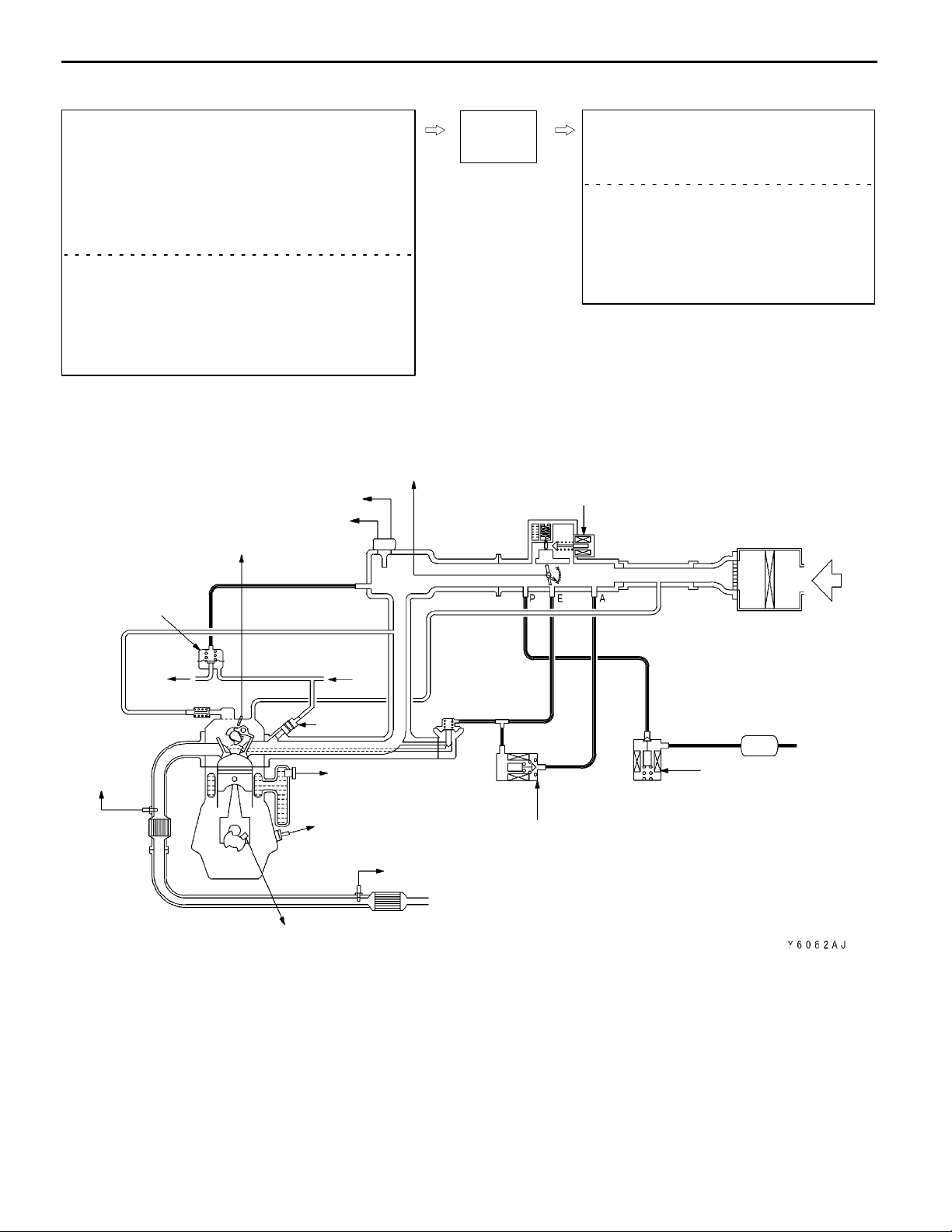
MPI <4G1> -
General Information
MULTI-POINT FUEL INJECTION SYSTEM DIAGRAM
13A-3
L1 Oxygen sensor (front)
L2 Vacuum sensor
L3 Intake air temperature sensor
L4 Throttle position sensor
L5 Camshaft position sensor
L6 Crank angle sensor
L7 Engine coolant temperature sensor
L8 Detonation sensor
L9 Oxygen sensor (rear)
D Power supply voltage
D Vehicle speed sensor
D A/C switch
D Power steering fluid pressure switch
D Vehicle speed sensor
D Ignition switch - ST
D Ignition switch - IG
L2 Vacuum sensor
L3 Intake air temperature sensor
L5 Camshaft position sensor
Engine-
ECU
L4 Throttle position sensor
l1 Injector
l2 Purge control solenoid valve
l3 Idle speed control valve
l4 EGR control servo valve
D Fuel pump relay
D Engine control relay
D A/C power relay
D Engine warning lamp
D Diagnosis signal
D Ignition coil (power transistor)
D Fan controller
l3 Idle speed control valve
Air cleaner
Fuel pressure
regulator
PCV valve
L1 Oxygen
sensor
(front)
Catalytic
converter
To fuel
tank
From fuel
pump
l1
Injector
L7 Engine coolant
L8 Detonation
L6 Crank angle sensor
EGR valve
temperature sensor
sensor
L9 Oxygen
sensor (rear)
Catalytic
converter
Air
Canister
l2 Purge control
solenoid valve
l4 EGR control solenoid valve
Page 34

13A-4
MPI <4G1> -
Service Specifications/Special Tools
SERVICE SPECIFICATIONS
Items Standard value
Intake air temperature sensor resistance kW 20_C 2.3 - 3.0
80_C 0.30 - 0.42
Oxygen sensor output voltage (during revving) V 0.6 - 1.0
Oxygen sensor heater resistance (at 20_C) W Front 4.5 - 8.0
Rear 11 - 18
SPECIAL TOOLS
Tool Number Name Use
MB991536 Throttle position
sensor adjustment
harness
MB991658 Test harness set D Measurement of voltage during trouble-
MD998464 Test harness
(4-pin, square)
MD998478 Test harness
(3-pin, triangle)
D Measurement of voltage during trouble-
shooting
shooting
D Measurement of voltage during trouble-
shooting
D Inspection of oxygen sensor (front)
D Measurement of voltage during trouble-
shooting
D Inspection using an analyzer
Page 35
MPI <4G1> -
TROUBLESHOOTING
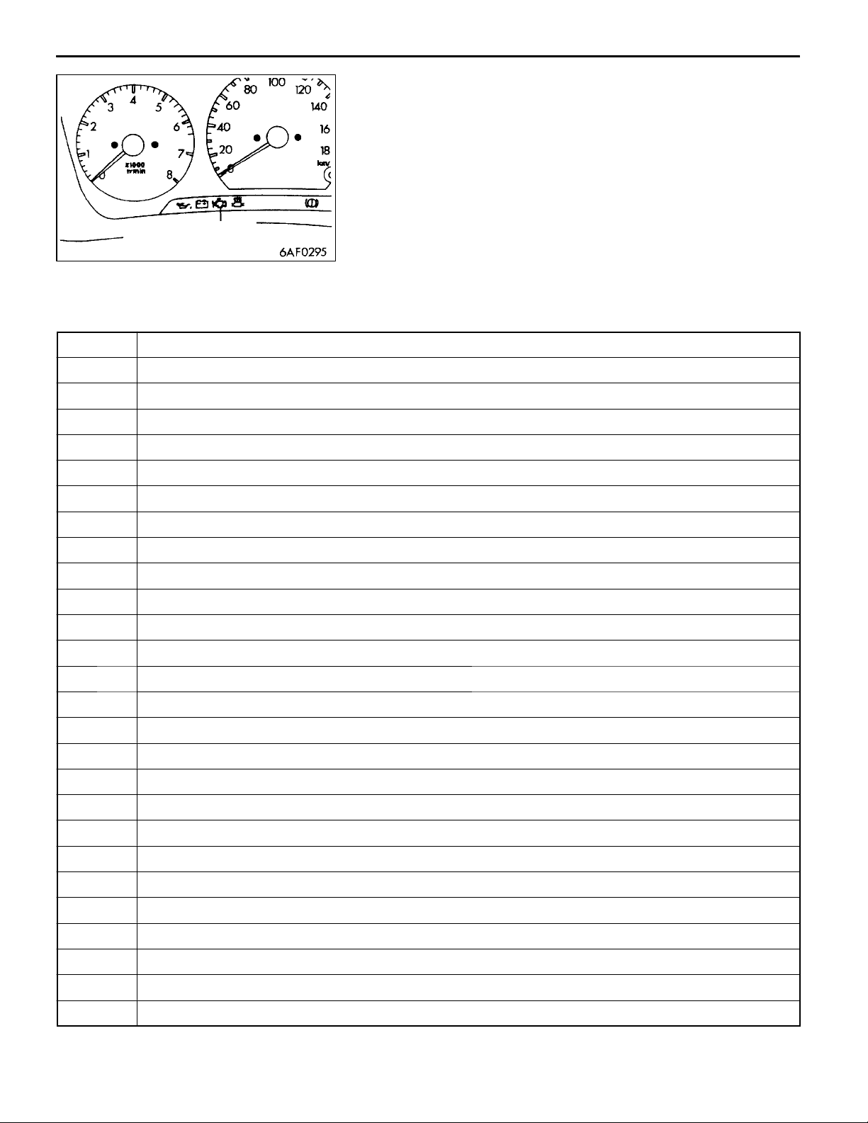
DIAGNOSIS FUNCTION
ENGINE WARNING LAMP (CHECK ENGINE LAMP)
If an abnormality occurs in any of the following items related
to the Multipoint Fuel Injection (MPI) system, the engine
warning lamp will illuminate. If th e lamp remains illuminated
Engine warning lamp
(check engine lamp)
Engine warning lamp inspection items
Code No. Diagnosis item
- Engine-ECU
P0105 Vacuum sensor system
P0110 Intake air temperature sensor system
P0115 Engine coolant temperature sensor system
or if the lamp illuminates while the engine is running, check
the diagnosis code output.
However, the warning lamp will illuminate as bulb check for
five seconds whenever the ignition switch is turned to the
ON position.
Troubleshooting
13A-5
P0120 Throttle position sensor system
P0125 Feedback system
P0130 Oxygen sensor (front) system <sensor 1>
P0135 Oxygen sensor heater (front) system <sensor 1>
P0136 Oxygen sensor (rear) system <sensor 2>
P0141 Oxygen sensor heater (rear) system <sensor 2>
P0170 Abnormal fuel system
P0201 No. 1 injector system
P0202 No. 2 injector system
P0203 No. 3 injector system
P0204 No. 4 injector system
L
P0300
P0301 No. 1 cylinder misfire detected
P0302 No. 2 cylinder misfire detected
P0303 No. 3 cylinder misfire detected
P0304 No. 4 cylinder misfire detected
Random cylinder misfire detected
P0335 Crank angle sensor system
P0340 Camshaft position sensor system
P0403 EGR control solenoid valve system
P0420 Catalyst malfunction
P0443 Purge control solenoid valve system
P0505 Idle speed control system
Page 36

13A-6
NOTE
1. If the engine warning lamp illuminates because of a malfunction of the engine-ECU, communication
between MUT-II and the engine-ECU is impossible. In this case, the diagnosis code cannot be read.
2. After the engine-ECU has detected a malfunction, the engine warning lamp illuminates when the
engine is next turned on and the same malfunction is re-detected. However, for items marked with
a“L” in the diagnosis code number column, the engine warning lamp illuminates only on the first
detection of the malfunction.
3. After the engine warning lamp illuminates, it will be switched off under the following conditions.
(1) When the engine-ECU monitored t he power train malfunction three times* and met set condition
requirements, it detected no malfunction.
*: In this case, “one time” indicates from engine start to stop.
(2) For misfiring malfunction, when driving conditions (engine speed, engine coolant temperature,
etc.) are similar to those when the malfunction was first recorded.
4. Sensor 1 indicates the sensor mounted at a position closest to the engine, and sensor 2 indicates
the sensor mounted at the position second closest to the engine.
MPI <4G1> -
Troubleshooting
METHOD OF READING AND ERASING DIAGNOSIS
CODES
Refer to GROUP 00 - How to Use Troubleshooting/Inspection
Service Points.
DIAGNOSIS USING DIAGNOSIS 2 MODE
1. Switch the diagnosis mode of the engine control unit
to DIAGNOSIS 2 mode using the MUT-II.
2. Carry out a road test.
3. Take a reading of the diagnosis code a n d repair the
problem location.
4. Turn the ignition switch to OFF and then back to ON
again.
NOTE
By turning the ignition switch to OFF, the engine-ECU
will switch the diagnosis mode from DIAGNOSIS 2 mode
to DIAGNOSIS 1 mode.
5. Erase the diagnosis codes.
INSPECTION USING MUT-IIDATA LIST AND
ACTUATOR TESTING
1. Carry out inspection by means of the data list and the
actuator test function. If there is an abnormality, check
and repair the chassis harnesses and components.
2. After repairing, re-check using the MUT-II and check that
the abnormal input and output have returned to normal
as a result of t he repairs.
3. Erase the diagnosis code memory.
4. Remove the MUT-II, and then start the engine again and
carry out a road test to confirm that the problem has
disappeared.
Page 37

MPI <4G1> -
FREEZE FRAME DATA
When the engine-ECU detects a malfunction and stores a
diagnosis code, it also stores a current status of the engine.
This function is called “freeze frame data.” By analyzing
this “freeze frame” data with the MUT-II, an effective
troubleshooting can be performed.
Displayed items of freeze frame data are shown in the
following:
DISPLAYED ITEM LIST
Data item Unit
Troubleshooting
13A-7
Engine coolant temperature sensor
Engine speed r/min
Vehicle speed km/h
Long-term fuel compensation (long-term
fuel trim)
Short-term fuel compensation (short-term
fuel trim)
Fuel control condi- Open loop OL
tion
Closed loop CL
Open loop owing to
drive condition
Open loop owing to
system malfunction
Closed loop based
on one oxygen sensor
Calculation load value %
_
C
%
%
OL-DRV.
OL-SYS.
CL-H02S
Diagnosis code during data recording -
NOTE
If malfunctions have been detected in multiple systems, store
one malfunction only, which has been detected first.
READINESS TEST STATUS
The engine-ECU monitors the following main diagnosis items,
judges if these items are in good condition or not, and the
stores its history. This history can be read out by using MUT-II.
(If the ECU has judged a item before, the MUT-II displays
“Complete.”)
In addition, if diagnosis codes are erased or the battery
cable is disconnected, this history will also be erased (the
memory will be reset).
D Catalyst: P0421
D Oxygen sensor: P0130
D Oxygen sensor heater: P0135, P0141
Page 38

13A-8
MPI <4G1> -
Troubleshooting
FAIL-SAFE FUNCTION REFERENCE TABLE
When the main sensor malfunctions are detected by the diagnosis function, the vehicle is controlled
by means of the pre-set control logic to maintain safe conditions for driving.
Malfunctioning item Control contents during malfunction
V acuum sensor 1. Uses the throttle position sensor signal and engine speed signal (crank angle sensor
signal) to take reading of the basic injector drive time and basic ignition timing from
the pre-set mapping.
2. Fixes the ISC servo in the appointed position so idle control is not performed.
Intake air temperature
sensor
Throttle position sensor (TPS)
Engine coolant temperature sensor
Camshaft position
sensor
Detonation sensor Switches the ignition timing from ignition timing for super petrol to ignition timing for standard
Oxygen sensor (front) Air/fuel ratio feedback control (closed loop control) is not performed.
Oxygen sensor (rear) Performs the feedback control (closed loop control) of the air/fuel ratio by using only the
Misfire detection The engine-ECU stops supplying fuel to the cylinder with the highest misfiring rate if a
Controls as if the intake air temperature is 45_C.
No increase in fuel injection amount during acceleration due to the throttle position sensor
signal.
Controls as if the engine coolant temperature is 80_C.
Injects fuelinto the cylinders inthe order 1-3-4-2with irregular timing. (After the ignitionswitch
is turned to ON, the No. 1 cylinder top dead centre is not detected at all.)
petrol.
signal of the oxygen sensor (front) installed on the front of the catalytic converter.
misfiring that could damage the catalytic converter is detected.
Page 39

MPI <4G1> -
Troubleshooting
INSPECTION CHART FOR DIAGNOSIS CODES
Code No. Diagnosis item Reference page
P0105 Vacuum sensor system 13A-10
P0110 Intake air temperature sensor system 13A-12
P0115 Engine coolant temperature sensor system 13A-13
P0120 Throttle position sensor system 13A-16
P0125 Feedback system 13A-18
P0130 Oxygen sensor (front) system <sensor 1> 13A-19
P0135 Oxygen sensor heater (front) system <sensor 1> 13A-21
P0136 Oxygen sensor (rear) system <sensor 2> 13A-22
P0141 Oxygen sensor heater (rear) system <sensor 2> 13A-24
P0170 Abnormal fuel system 13A-25
P0201 No. 1 injector system 13A-26
P0202 No. 2 injector system 13A-26
P0203 No. 3 injector system 13A-26
13A-9
P0204 No. 4 injector system 13A-26
P0300L Random cylinder misfire detected 13A-27
P0301 No. 1 cylinder misfire detected 13A-28
P0302 No. 2 cylinder misfire detected 13A-28
P0303 No. 3 cylinder misfire detected 13A-28
P0304 No. 4 cylinder misfire detected 13A-28
P0325 Detonation sensor system 13A-29
P0335 Crank angle sensor system 13A-29
P0340 Camshaft position sensor system 13A-31
P0403 EGR control solenoid valve system 13A-32
P0421 Catalyst malfunction 13A-33
P0443 Purge control solenoid valve system 13A-34
P0500 Vehicle speed sensor system 13A-35
P0505 Idle speed control system 13A-36
P1610 Immobilizer system 13A-38
NOTE
1. Do not replace the engine-ECU until a through terminal check reveals there are no short/open circuit.
2. Check that the engine-ECU earth circuit is normal before checking for the cause of the problem.
3. After the engine-ECU has detected a malfunction, a diagnosis code is recorded the next time the
engine is started and the same malfunction is re-detected. However, for items marked with a “L”,
the diagnosis code is recorded on the first detection of the malfunction.
4. Sensor 1 indicates the sensor mounted at a position closest to the engine, and sensor 2 indicates
the sensor mounted at the position second closest to the engine.
Page 40
13A-10
MPI <4G1> -
Troubleshooting
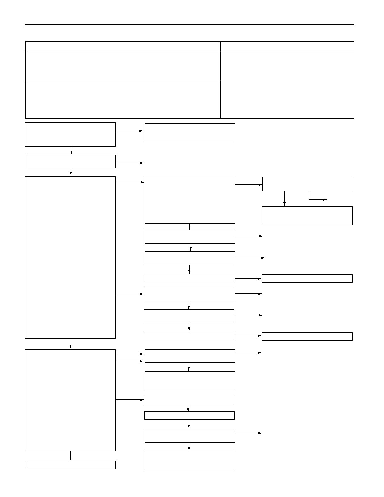
INSPECTION PROCEDURE CLASSIFIED BY DIAGNOSIS CODE
Code No. P0105 Vacuum sensor system Range of Check
Range of Check
D Ignition switch: ON
Set Conditions
D The output voltage of the vacuum sensor is 4.5 V or more for 2 seconds.
(This corresponds to the absolute manifold pressure of 115 kPa or more.)
Range of Check
D The output voltage of the throttle position sensor is 1.25 V or more.
or
D The vehicle is stationary.
Set Conditions
D The output voltage of the vacuum sensor is 0.2 V or less for 2 seconds.
(This corresponds to the absolute manifold pressure of 4.9 kPa or less.)
D Malfunction of the vacuum sensor
D Improper connector contact, open circuit or
short-circuited harness
D Malfunction of the engine-ECU
MUT-IIData list
32 Barometric pressure sensor
(Refer to P.13A-65, DATA LIST
REFERENCE TABLE.)
NG
Check the following connector:
A-54
OK
Measure at vacuum sensor
connector A-54.
D Disconnect the connector and
measure at the harness side.
(1) Voltage between terminal 3 and
earth (Ignition switch: ON)
OK:
(2) Resistance between terminal 2
Measure at vacuum sensor
connector A-54.
D Connect connector terminals No.
D Ignition switch: ON
(1) Voltage between terminal 3 and
(2) Voltage between terminal 1 and
(3) Voltage between terminal 2 and
To the next page
4.8 - 5.2 V
and earth
OK:
2 W or less
OK
1, No. 2 and No. 5 only by using
test harness (MB991348), and
measure at the pick-up harness.
earth
OK:
4.8 - 5.2 V
earth
OK:
Altitude 0 m: 3.7 - 4.3 V
Altitude 1,200 m:
3.2 - 3.8 V
earth
OK:
0.5 V or less
OK
OK
NG
(1) NG
(2) NG
(1) NG
(3) NG
(2) NG
Transient malfunction
(Refer to GROUP 00 - Points to
Note for Intermittent Malfunctions.)
Repair
Measure at engine-ECU connector
B-34.
D Measure the voltage at the
engine-ECU terminal.
D Ignition switch: ON
D Voltage between terminal 81 and
earth
OK:
4.8 - 5.2 V
NG
Check the following connector:
B-34
OK
Check the harness between the
vacuum sensor and the engine-ECU.
OK
Check the trouble symptoms.
Check the following connector:
B-34
OK
Check the harness between the
vacuum sensor and the engine-ECU.
OK
Check the trouble symptoms.
Check the following connector:
B-34
OK
Check the harness between the
vacuum sensor and the engine-ECU,
and repair if necessary.
Replace the vacuum sensor.
Check the trouble symptoms.
NG
Check the following connector:
B-34
OK
Check the harness between the
vacuum sensor and the engine-ECU,
and repair if necessary.
OK
NG
NG
NG
NG
NG
NG
NG
NG
Check the following connector:
B-34
OK
Check the harness between the
vacuum sensor and the engine-ECU,
and repair if necessary.
Repair
Repair
Replace the engine-ECU.
Repair
Repair
Replace the engine-ECU.
Repair
Repair
NG
Repair
Page 41

From the previous page
OK
Measure at engine-ECU connector
B-34.
D Measure the voltage at the
engine-ECU terminal.
D Ignition switch: ON
D Voltage between terminal 85 and
earth
OK:
Altitude 0 m: 3.7 - 4.3 V
Altitude 1,200 m:
3.2 - 3.8 V
MPI <4G1> -
NG
OK
Check the following connector:
B-34
Check the harness between the
vacuum sensor and the engine-ECU,
and repair if necessary.
Check the following connector:
B-34
Check the trouble symptoms.
Replace the engine-ECU.
Troubleshooting
NG
OK
NG
OK
NG
13A-11
Repair
Repair
Page 42
13A-12
MPI <4G1> -
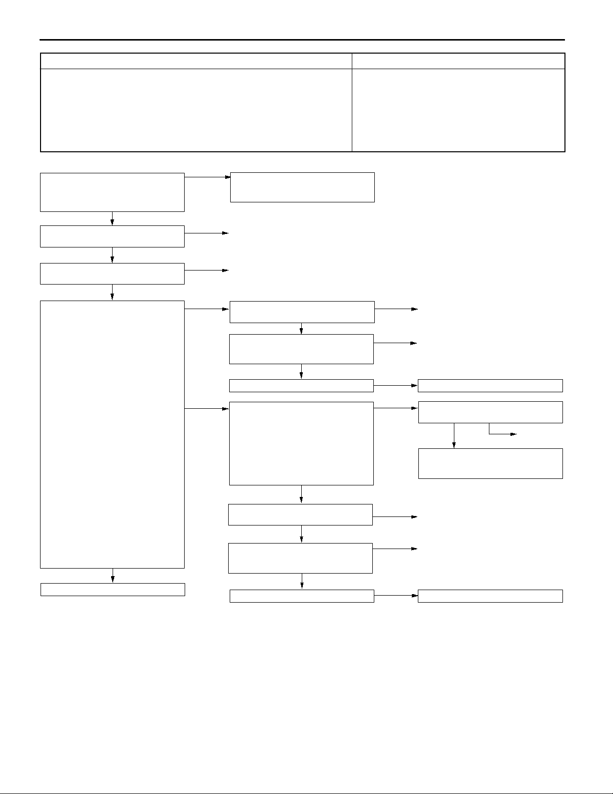
Troubleshooting
Code No. P0110 Intake air temperature sensor system Probable cause
Range of Check
D Two seconds have passed since the ignition switch is turned ON or the
engine starting process is completed.
Set Conditions
D The sensor output voltage is 4.6 V or more for two seconds (equivalent to
-45_C of intake air temperature)
or
D The sensor output voltage is 0.2 V or more for two seconds (equivalent to
125_C of intake air temperature)
D Malfunction of intake air temperature sensor
D Open or short circuit in intake air temperature
sensor or loose connector contact
D Malfunction of engine-ECU
MUT-IIData list
13 Intake air temperature sensor
OK:
Roughly the same as ambient temperature.
NG
Check the intake air temperature
sensor. (Refer to P.13A-80.)
OK
Check the following connector:
A-54
OK
Measure at vacuum sensor
connector A-54.
D Disconnect the connector and
measure at the harness side.
(1) Resistance between terminal 2
and earth
OK:
(2) Voltage between terminal 3 and
2 W or less
earth
(Ignition switch: ON)
OK:
4.8 - 5.2 V
OK
NG
NG
(1) NG
(2) NG
Transient malfunction
(Refer to GROUP 00 - Points to
Note for Intermittent Malfunctions.)
Repair
Repair
B-34
OK
Check the harness between the
intake air temperature sensor and
the engine-ECU.
OK
Check the trouble symptoms.
Measure at engine-ECU connector
B-34.
D Measure the voltage at the
engine-ECU terminal.
D Disconnect connector A-54.
D Ignition switch: ON
D Voltage between terminal 81 and
earth
OK:
4.8 - 5.2 V
NG
NG
NG
NG
OK
RepairCheck the following connector:
Repair
Replace the engine-ECU.
Check the following connector:
B-34
OK
Check the harness between the air
flow sensor and the engine-ECU,
and repair if necessary.
NG
Repair
To the next page
OK
Check the following connector:
B-34
OK
Check the harness between the
intake air temperature sensor and
the engine-ECU.
OK
Check the trouble symptoms.
NG
NG
NG
Repair
Repair
Replace the engine-ECU.
Page 43

From the previous page
OK
Measure at intake air temperature
sensor connector A-54.
D Use the test harness (MB991348)
to connect only terminals 1 and
3, and then measure at the
pick-up harness.
D Ignition switch: ON
D Voltage between terminal 1 and
earth
OK:
Ambient temperature 0_C:
3.2 - 3.8 V
Ambient temperature 20_C:
2.3 - 2.9 V
Ambient temperature 40_C:
1.5 - 2.1 V
Ambient temperature 80_C:
0.4 - 1.0 V
OK
Check the trouble symptoms.
MPI <4G1> -
NG
NG
Check the following connector:
B-34
Check the harness between the
intake air temperature sensor and
the engine-ECU, and repair if
necessary.
Replace the engine-ECU.
Troubleshooting
NG
OK
13A-13
Repair
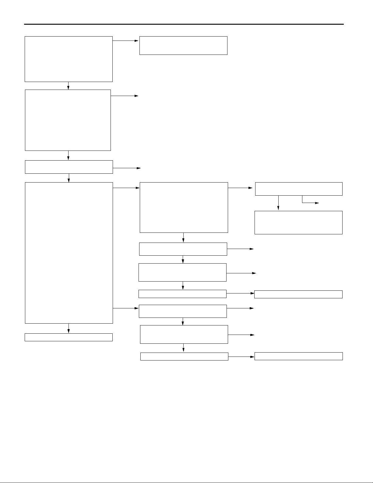
Code No. P0115 Engine coolant temperature sensor
system
Range of Check
D Engine: Two seconds after the engine has been started
Set Conditions
D The sensor output voltage is 4.6 V or more for two seconds (equivalent to
-45_C of engine coolant temperature)
or
D The sensor output voltage is 0.1 V or less for two seconds (equivalent to
140_C of engine coolant temperature)
Range of Check
D Engine: After starting
Set Conditions
D The engine coolant temperature has reduced from over 40_C to less than
40_C, and that condition has lasted for five minutes or more.
Probable cause
D Malfunction of engine coolant temperature sensor
D Open or short circuit in the engine coolant
temperature sensor circuit or loose connector
contact
D Malfunction of engine-ECU
Page 44
13A-14
MPI <4G1> -
Troubleshooting
MUT-IIData list
21 Engine coolant temperature
sensor
OK:
When the engine is cold,
the temperature is roughly
the same as ambient temperature. If warm, it is 80 120_C.
NG
Measure at engine coolant
temperature sensor connector A-72.
D Disconnect the connector and
measure at the harness side.
D Resistance between terminals 1
and 2
OK:
At 20_C of engine coolant
temperature: 2.1 - 2.7 kW
At 80_C of engine coolant
temperature: 0.26 - 0.36
kW
OK
Check the following connector:
A-72
OK
Measure at engine coolant
temperature sensor connector A-72.
D Disconnect the connector and
measure at the harness side.
(1) Voltage between terminal 1 and
earth
(Ignition switch: ON)
OK:
(2) Resistance between terminal 2
To the next page
4.8 - 5.2 V
and earth
OK:
2 W or less
OK
OK
NG
NG
(1) NG
(2) NG
Transient malfunction
(Refer to GROUP 00 - Points to
Note for Intermittent Malfunctions.)
Replace
Repair
Measure at engine-ECU connector
B-34.
D Measure the voltage at the
engine-ECU terminal.
D Disconnect connector A-72.
D Ignition switch: ON
D Voltage between terminal 44 and
earth
OK:
4.8 - 5.2 V
NG
Check the following connector:
B-34
OK
Check the harness wire between the
engine coolant temperature sensor
and the engine-ECU.
OK
Check the trouble symptoms.
Check the following connector:
B-34
OK
Check the harness wire between the
engine coolant temperature sensor
and the engine-ECU.
OK
Check the trouble symptoms.
NG
NG
NG
NG
NG
OK
NG
Check the following connector:
B-34
OK
Check the harness wire between the
engine coolant temperature sensor
and the engine-ECU, and repair if
necessary.
Repair
Repair
Replace the engine-ECU.
Repair
Repair
Replace the engine-ECU.
NG
Repair
Page 45

From the previous page
OK
Measure at engine coolant
temperature sensor connector A-72.
D Use test harness (MB991658) to
connect the connector, and
measure at the pick-up harness.
D Ignition switch: ON
D Voltage between terminal 1 and
earth
OK:
At 0_C of engine coolant
temperature: 3.2 - 3.8 V
At 20_C of engine coolant
temperature: 2.3 - 2.9 V
At 40_C of engine coolant
temperature: 1.3 - 1.9 V
At 80_C of engine coolant
temperature: 0.3 - 0.9 V
OK
Check the trouble symptoms.
MPI <4G1> -
NG
NG
Check the engine coolant
temperature sensor.
(Refer to P.13A-83*.)
Check the following connector:
B-34
Check the harness wire between the
engine coolant temperature sensor
and the engine-ECU, and repair if
necessary.
Replace the engine-ECU.
Troubleshooting
NG
OK
OK
NG
Repair
Repair
NOTE:
*: Refer to the ’96 COLT/LANCER Workshop Manual (Pub. No. PWME9511).
13A-15
Page 46

13A-16
MPI <4G1> -
Troubleshooting
Code No. 0120 Throttle position sensor system Probable cause
Range of Check
D Ignition switch: ON
D Excluding 2 seconds after the ignition switch is turned to ON or immediately
after the engine starts.
Set Conditions
D Engine speed is 1,000 r/min or less, and intake air pressure is 48 kPa or
less, TPS output voltage is 4.6 V or more for 2 seconds.
or
D The sensor output voltage is 0.2 V or less for 2 seconds.
D Malfunction of throttle position sensor
D Open or short circuit in the throttle position sensor
circuit or loose connector contact
D Malfunction of the engine-ECU
MUT-IIData list
14 Throttle position sensor
OK:
Refer to P.13A-65, DATA
LIST REFERENCE TABLE.
NG
Check throttle position sensor.
(Refer to P.13A-84*.)
OK
Check the following connector:
A-05
OK
Measure at throttle position sensor
connector A-05.
D Disconnect the connector and
measure at the harness side.
(1) The voltage between terminal 1
and earth
(Ignition switch: ON)
OK:
(2) Resistance between terminal 4
4.8 - 5.2 V
and earth
OK:
2 W or less
OK
NG
NG
(1) NG
Intermittent malfunction
(Refer to GROUP 00 - Points to
Note for Intermittent Malfunctions.)
Replace
Repair
Measure at engine-ECU connector
B-34.
D Measure the voltage at the
engine-ECU connector terminal.
D Ignition switch: ON
D The voltage between terminal 81
and earth
OK:
4.8 - 5.2 V
NG
Check the following connector:
B-34
OK
Check the harness wire between the
throttle position sensor and the
engine-ECU.
OK
Check the trouble symptoms.
OK
NG
NG
NG
Check the following connector:
B-34
OK
Check the harness wire between the
throttle position sensor and the
engine-ECU, and repair if necessary.
Repair
Repair
Replace the engine-ECU.
NG
Repair
NG
NG
NG
Repair
Repair
Replace the engine-ECU.
To the next page
OK
(2) NG
Check the following connector:
B-34
OK
Check the harness wire between the
throttle position sensor and the
engine-ECU.
OK
Check the trouble symptoms.
NOTE:
*: Refer to the ’96 COLT/LANCER Workshop Manual (Pub. No. PWME9511).
Page 47

From the previous page
OK
Measure at throttle position sensor
connector A-05.
D Use test harness (MB991536) to
connect the connector, and
measure at the pick-up harness.
D Ignition switch: ON
(1) The voltage between terminal 1
and earth
OK:
(2) The voltage between terminal 4
(3) The voltage between terminal 2
Measure at engine-ECU connector
B-34.
D Measure the voltage at the
D Ignition switch: ON
D The voltage between terminal 84
4.8 - 5.2 V
and earth
OK:
0.5 V or less
and earth
OK:
Accelerator pedal fully released: 0.3 - 1.0 V
Accelerator pedal fully depressed: 4.5 - 5.5 V
OK
engine-ECU terminal.
and earth
OK:
Accelerator pedal fully released: 0.3 - 1.0 V
Accelerator pedal fully depressed: 4.5 - 5.5 V
MPI <4G1> -
(1), (2) NG
(3) NG
NG
OK
Check the following connector:
B-34
Check the harness wire between
throttle position sensor and the
engine-ECU.
Adjust the throttle position sensor.
(Refer to P.13A-84*.)
Check the following connector:
B-34
Check the harness wire between
throttle position sensor and the
engine-ECU, and repair if necessary.
Troubleshooting
OK
OK
Check the following connector:
B-34
OK
Check the harness wire between
throttle position sensor and the
engine-ECU, and repair if necessary.
Check the following connector:
B-34
OK
Check the trouble symptoms.
NG
Replace the engine-ECU.
NG
NG
NG
NG
13A-17
Repair
Repair
Repair
Repair
NOTE:
*: Refer to the ’96 COLT/LANCER Workshop Manual (Pub. No. PWME9511).
Page 48

13A-18
MPI <4G1> -
Troubleshooting
Code No. P0125 Feedback system Probable cause
Range of Check
D The engine coolant temperature is approx. 80_C or more.
D During stoichiometric feedback control
D The vehicle is not being decelerated.
Set Conditions
D Oxygen sensor (front) output voltage has been higher or lower than 0.5 V for
at least thirty seconds.
D Malfunction of oxygen sensor (front)
D Open or short circuit in the oxygen sensor (front)
circuit or loose connector contact
D Malfunction of engine-ECU
Check the following connector:
A-106
OK
Measure at oxygen sensor (front)
connector A-106.
D Disconnect the connector and
measure at the harness side.
D Resistance between terminal 2
and earth
OK:
2 W or less
OK
Measure at oxygen sensor (front)
connector A-106.
D Use the test harness
(MD998464) to connect the
connector, and measure at the
pick-up harness side.
D Engine: 2,500 r/min (after
warming up)
(1) Voltage between terminal 2 and
earth
OK:
(2) Voltage between terminal 4 and
Measure at engine-ECU connector
B-34.
D Measure the voltage at the
D Engine: 2,500 r/min (after
D Voltage between terminal 76 and
Check the following connector:
B-34
Check the trouble symptoms.
Replace the engine-ECU.
0.5 V or less
earth
OK:
0 V and 0.8 V alternate.
OK
engine-ECU terminal.
warming up)
earth
OK:
0 V and 0.8 V alternate.
OK
OK
NG
NG
NG
(1) NG
(2) NG
NG
NG
OK
Repair
Check the following connector:
B-34
OK
Check the harness wire between the
oxygen sensor (front) and the
engine-ECU.
OK
Check the trouble symptoms.
NG
Replace the engine-ECU.
Check the following connector:
B-34
OK
Check the harness wire between the
oxygen sensor (front) and the
engine-ECU, and repair if necessary.
Check the oxygen sensor (front).
(Refer to P.13A-80.)
OK
Check the following connector:
B-34
OK
Check the harness wire between the
oxygen sensor (front) and the
engine-ECU, and repair if necessary.
Check the following connector:
B-34
OK
Check the harness wire between the
oxygen sensor (front) and the
engine-ECU, and repair if necessary.
Repair
Transient malfunction
(Refer to GROUP 00 - Points to
Note for Intermittent Malfunctions.)
NG
NG
NG
NG
NG
NG
Repair
Repair
Repair
Replace
Repair
Repair
Page 49

MPI <4G1> -
Troubleshooting
13A-19
Code No. P0130 Oxygen sensor (front) system
<sensor 1>
Range of Check
D Three minutes have been passed since the engine has been started.
D The engine coolant temperature is approx. 80_C or more.
D Intake air temperature is 20 - 50_C
D Engine speed is 1,200 r/min or more
D Driving on a level surface at constant speed.
Set Conditions
D The oxygen sensor (front) output voltage is 4.5 V or more when the sensor
output voltage is 0.2 V or less and a voltage of 5 V is applied to the oxygen
sensor (front) inside the engine-ECU.
Range of Check
D Engine speed is 2,800 r/min or less
D During driving
D During air/fuel ratio feedback control
Set Conditions
D The oxygen sensor (front) output frequency is six or less per 10 seconds on
average.
Probable cause
D Malfunction of oxygen sensor (front)
D Open or short circuit in the oxygen sensor (front)
circuit or loose connector contact
D Malfunction of engine-ECU
Page 50

13A-20
MPI <4G1> -
Troubleshooting
Check the following connector:
A-106
OK
Measure at oxygen sensor (front)
connector A-106.
D Disconnect the connector and
measure at the harness side.
D Resistance between terminal 2
and earth
OK:
2 W or less
OK
Measure at oxygen sensor (front)
connector A-106.
D Use the test harness
(MD998464) to connect the
connector, and measure at the
pick-up harness side.
D Engine: 2,500 r/min (after
warming up)
(1) Voltage between terminal 2 and
earth
OK:
(2) Voltage between terminal 4 and
Measure at engine-ECU connector
B-34.
D Measure the voltage at the
D Engine: 2,500 r/min (after
D Voltage between terminal 76 and
Check the following connector:
B-34
Check the trouble symptoms.
Replace the engine-ECU.
0.5 V or less
earth
OK:
0 V and 0.8 V alternate.
OK
engine-ECU terminal.
warming up)
earth
OK:
0 V and 0.8 V alternate.
OK
OK
NG
NG
NG
(1) NG
(2) NG
NG
NG
OK
Repair
Check the following connector:
B-34
OK
Check the harness wire between the
oxygen sensor (front) and the
engine-ECU.
OK
Check the trouble symptoms.
NG
Replace the engine-ECU.
Check the following connector:
B-34
OK
Check the harness wire between the
oxygen sensor (front) and the
engine-ECU, and repair if necessary.
Check the oxygen sensor (front).
(Refer to P.13A-80.)
OK
Check the following connector:
B-34
OK
Check the harness wire between the
oxygen sensor (front) and the
engine-ECU, and repair if necessary.
Check the following connector:
B-34
OK
Check the harness wire between the
oxygen sensor (front) and the
engine-ECU, and repair if necessary.
Repair
Transient malfunction
(Refer to GROUP 00 - Points to
Note for Intermittent Malfunctions.)
NG
NG
NG
NG
NG
NG
Repair
Repair
Repair
Replace
Repair
Repair
Page 51

MPI <4G1> -
Troubleshooting
13A-21
Code No. P0135 Oxygen sensor heater (front) system
<sensor 1>
Range of Check
D The engine coolant temperature is approx. 20_C or more.
D The oxygen sensor heater (front) remains on.
D The engine speed is 50 r/min or more.
D Battery voltage is 11 - 16 V.
Set Conditions
D The current, which flows through the oxygen sensor heater (front), is 0.2 A
or less or 3.5 A or more for six seconds.
Measure at oxygen sensor (front)
connector A-106.
D Disconnect the connector and
measure at the harness side.
D Resistance between terminals 1
and 3
OK:
4.5 - 8.0 W
OK
Check the following connector:
A-106
OK
Measure at oxygen sensor (front)
connector A-106.
D Disconnect the connector and
measure at the harness side.
D Ignition switch: ON
D Voltage between terminal 1 and
earth
OK:
System voltage
OK
Measure at engine-ECU connector
B-35.
D Measure the voltage at the
engine-ECU terminal.
D Ignition switch: ON
D Voltage between terminal 60 and
earth
OK:
System voltage
OK
Check the following connector:
B-35
OK
Check the harness wires between
the oxygen sensor (front) and the
engine-ECU and between the oxygen
sensor (front) and the engine control
relay.
OK
Check the trouble symptoms.
NG
Replace the engine-ECU.
NG
NG
NG
NG
NG
NG
OK
Replace
Repair
Check the following connector:
B-13
OK
Check the harness wires between
the oxygen sensor (front) and the
engine control relay, and repair if
necessary.
Check the following connector:
B-35
OK
Check the harness wire between the
oxygen sensor (front) and the
engine-ECU.
OK
Replace the engine-ECU.
Repair
Repair
Transient malfunction
(Refer to GROUP 00 - Points to
Note for Intermittent Malfunctions.)
Probable cause
D Malfunction of oxygen sensor heater (front)
D Open or short circuit in the oxygen sensor heater
(front) circuit or loose connector contact
D Malfunction of engine-ECU
NG
NG
NG
Repair
Repair
Repair
Page 52

13A-22
MPI <4G1> -
Troubleshooting
Code No. P0136 Oxygen sensor (rear) system
<sensor 2>
Range of Check
D Three minutes have been passed since the engine has been started.
D The engine coolant temperature is approx. 80_C or more.
D Intake air temperature is 20 - 50_C
D Engine speed is 1,200 r/min or more
D Driving on a level surface at constant speed.
Set Conditions
D The oxygen sensor (rear) output voltage is 4.5 V or more when the sensor
output voltage is 0.2 V or less and a voltage of 5 V is applied to the oxygen
sensor (rear) inside the engine-ECU.
Range of Check
D Two seconds have passed after the ECU detected an open circuit.
D When the oxygen sensor (front) is in good condition.
Set Conditions
D When the air/fuel ratio is rich, the oxygen sensor (front) output voltage is 0.5
V or more, the oxygen sensor (rear) output voltage is less than 0.1 V, and
the oxygen sensor (rear) output voltage fluctuates within 0.078 V.
Probable cause
D Malfunction of oxygen sensor (rear)
D Open or short circuit in the oxygen sensor (rear)
circuit or loose connector contact
D Malfunction of engine-ECU
Page 53
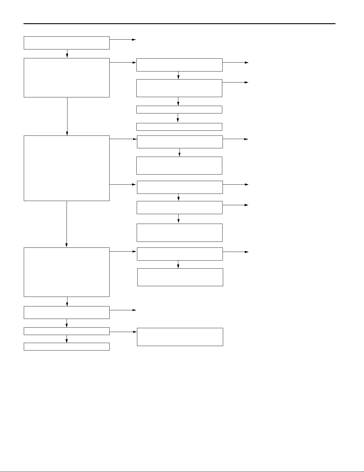
MPI <4G1> -
Troubleshooting
13A-23
Check the following connector:
A-108
OK
Measure at oxygen sensor (rear)
connector A-108.
D Disconnect the connector and
measure at the harness side.
D Resistance between terminal 2
and earth
OK:
2 W or less
OK
Measure at oxygen sensor (rear)
connector A-108.
D Measure the voltage at the
oxygen sensor (rear) terminal
D Engine: 2,500 r/min (after
warming up)
(1) Voltage between terminal 2 and
earth
OK:
(2) Voltage between terminal 4 and
Measure at engine-ECU connector
B-34.
D Measure the voltage at the
D Engine: 2,500 r/min (after
D Voltage between terminal 75 and
Check the following connector:
B-34
Check the trouble symptoms.
Replace the engine-ECU.
0.5 V or less
earth
OK:
0 V and 0.8 V alternate.
OK
engine-ECU terminal.
warming up)
earth
OK:
0 V and 0.8 V alternate.
OK
OK
NG
NG
NG
(1) NG
(2) NG
NG
NG
OK
Repair
Check the following connector:
B-34
OK
Check the harness wire between the
oxygen sensor (rear) and the
engine-ECU.
OK
Check the trouble symptoms.
NG
Replace the engine-ECU.
Check the following connector:
B-34
OK
Check the harness wire between the
oxygen sensor (rear) and the
engine-ECU, and repair if necessary.
Check the oxygen sensor (rear).
(Refer to P.13A-81.)
OK
Check the following connector:
B-34
OK
Check the harness wire between the
oxygen sensor (rear) and the
engine-ECU, and repair if necessary.
Check the following connector:
B-34
OK
Check the harness wire between the
oxygen sensor (rear) and the
engine-ECU, and repair if necessary.
Repair
Transient malfunction
(Refer to GROUP 00 - Points to
Note for Intermittent Malfunctions.)
NG
NG
NG
NG
NG
NG
Repair
Repair
Repair
Replace
Repair
Repair
Page 54

13A-24
MPI <4G1> -
Troubleshooting
Code No. P0141 Oxygen sensor heater (rear) system
<sensor 2>
Range of Check
D The engine coolant temperature is approx. 20_C or more.
D The oxygen sensor heater (rear) remains on.
D The engine speed is 50 r/min or more.
D Battery voltage is 11 - 16 V.
Set Conditions
D The current, which flows through the oxygen sensor heater (rear), is 0.2 A or
less or 3.5 A or more for six seconds.
Measure at oxygen sensor (rear)
connector A-108.
D Disconnect the connector and
measure at the harness side.
D Resistance between terminals 1
and 3
OK:
11 - 1 8 W
OK
Check the following connector:
A-108
OK
Measure at oxygen sensor (rear)
connector A-108.
D Disconnect the connector and
measure at the harness side.
D Ignition switch: ON
D Voltage between terminal 1 and
earth
OK:
System voltage
OK
Measure at engine-ECU connector
B-35.
D Measure the voltage at the
engine-ECU terminal.
D Ignition switch: ON
D Voltage between terminal 54 and
earth
OK:
System voltage
OK
Check the following connector:
B-35
OK
Check the harness wires between
the oxygen sensor (rear) and the
engine-ECU, and between the
oxygen sensor (rear) and the engine
control relay.
OK
Check the trouble symptoms.
NG
Replace the engine-ECU.
NG
NG
NG
NG
NG
NG
OK
Replace
Repair
Check the following connector:
B-13
OK
Check the harness wires between
the oxygen sensor (rear) and the
engine control relay, and repair if
necessary.
Check the following connector:
B-35
OK
Check the harness wire between the
oxygen sensor (rear) and the
engine-ECU, and repair if necessary.
Repair
Repair
Transient malfunction
(Refer to GROUP 00 - Points to
Note for Intermittent Malfunctions.)
Probable cause
D Malfunction of oxygen sensor heater (rear)
D Open or short circuit in the oxygen sensor heater
(rear) circuit or loose connector contact
D Malfunction of engine-ECU
NG
NG
Repair
Repair
Page 55

MPI <4G1> -
Troubleshooting
Code No. P0170 Abnormal fuel system Probable cause
Range of Check
D Engine: Being learning the air-fuel ratio
Set Conditions
D Two seconds or more have been passed while the fuel injection amount
compensation value is too low.
or
D Two seconds or more have been passed while the fuel injection amount
compensation value is too high.
D Incorrect fuel pressure
D Malfunction of injector
D Malfunction of oxygen sensor (front)
D Malfunction of intake air temperature sensor
D Malfunction of vacuum sensor
D Malfunction of engine-ECU
13A-25
MUT-IIData list
13 Intake air temperature sensor (Refer to P.13A-65.)
OK
MUT-IIData list
21 Engine coolant temperature sensor (Refer to P.13A-66.)
OK
MUT-IIData list
32 Vacuum sensor (Refer to P.13A-67.)
OK
Check the injector (Refer to P.13A-86*.)
OK
Check the following connectors:
Check the harness wire between the engine-ECU and the
injector connector.
Check the fuel pressure (Refer to P.13A-78*.)
MUT-IIData list
81 Long-term fuel compensation (Refer to P.13A-69.)
D Is fuel trim more or less than zero?
D Check for fuel leaks from injector.
D Check for entry of foreign matter (water, kerosene, etc.) into
the fuel.
Replace the engine-ECU.
A-74, A-75, A-76, A-80
OK
OK
OK
Less than zero
OK
NG
NG
NG
NG
NG
NG
NG
NGNG
NG
NGNG
More than zero
Check the intake air temperature sensor system
(Refer to P.13A-12, INSPECTION PROCEDURE FOR DIAGNOSTIC TROUBLE CODE P0110.)
Check the engine coolant temperature sensor system
(Refer to P.13A-13, INSPECTION PROCEDURE FOR DIAGNOSTIC TROUBLE CODE P0115.)
Check the vacuum sensor system
(Refer to P.13A-10, INSPECTION PROCEDURE FOR DIAGNOSTIC TROUBLE CODE P0105.)
Replace
Replace
Repair
Repair
Check if air was drawn
into the intake system.
D Check for clogging of the injector.
D Check for clogging of the fuel filter and fuel line.
D Check the fuel pump (insufficient discharge rate).
D Check for exhaust leaks (oxygen sensor installation section,
D Check for entry of foreign matter (water, kerosene, etc.) into
Replace the engine-ECU.
NG
NGNG
OK
cracks in exhaust manifold, cracks in front pipe, etc.).
the fuel.
OK
Repair
NOTE:
*: Refer to the ’96 COLT/LANCER Workshop Manual (Pub. No. PWME9511).
Page 56

13A-26
MPI <4G1> -
Troubleshooting
Code No. P0201 No. 1 injector system
Code No. P0202 No. 2 injector system
Code No. P0203 No. 3 injector system
Code No. P0204 No. 4 injector system
Range of Check
D Engine speed is approx. 50 - 1,000 r/min
D The throttle position sensor output voltage is 1.15 V or less.
D Actuator test by MUT-II is not carried out.
Set Conditions
D Surge voltage of injector coil is not detected for 2 seconds.
MUT-IIActuator Test
01 No. 1 injector
02 No. 2 injector
03 No. 3 injector
04 No. 4 injector
OK:
The idling condition should change
NG
Check the following connectors:
A-74, A-75, A-76, A-80
OK
Check the injector. (Refer to P.13A-86*.)
OK
Measure at the injector connectors A-74, A-75, A-76, A-80.
D Disconnect the connector, and measure at the harness side.
D Voltage between 1 and earth (Ignition switch: ON)
OK:
System voltage
OK
Check the following connector:
Measure at the engine-ECU connector B-37.
D Disconnect the connector, and measure at the harness side.
D Voltage between 1, 2, 14, 15 and earth (Ignition switch: ON)
OK:
System voltage
Check the trouble symptoms.
Use an analyzer to measure the signal waveform at injector
connectors A-74, A-75, A-76, A-80.
D Connect the connector using test harness (MB991348), and
measure at pick-up harness.
D Engine: Idling
D The voltage between terminal 2 and earth
OK:
A normal waveform should be displayed as described
on P.13A-69* (INSPECTION PROCEDURE USING AN
ANALYZER).
B-37
OK
OK
NG
NG
OK
NG
NG
NG
NG
NGNG
NG
OK
Probable cause
D Malfunction of the injector
D Improper connector contact, open circuit or
short-circuited harness wire of the injector circuit
D Malfunction of the engine-ECU
Intermittent malfunction
(Refer to GROUP 00 - Points to Note for Intermittent Malfunctions.)
Repair
Replace
Check the harness wire between the engine control relay and the
injector connector, and repair if necessary.
Repair
Check the harness wire between the engine-ECU and the injector
connector, and repair if necessary.
Intermittent malfunction
(Refer to GROUP 00 - Points to Note for Intermittent Malfunctions.)
Replace the engine-ECU.
NOTE:
*: Refer to the ’96 COLT/LANCER Workshop Manual (Pub. No. PWME9511).
Page 57

MPI <4G1> -
Troubleshooting
Code No. P0300 Random cylinder misfire detected Probable cause
Range of Check
D Engine speed is approx. 50 - 4,500 r/min.
D When the engine is running except deceleration and sudden acceleration.
Set Conditions
D The number of misfires exceeds a predetermined number per 200 engine
revolutions.
D The number of misfires exceeds a predetermined number per 1,000 engine
revolutions.
D Malfunction of the ignition system
D Abnormal compression
D Malfunction of injector
D Abnormal signal from the crank angle sensor
D Malfunction of the lambda control system
D Malfunction of the engine coolant temperature
sensor
D Missing timing belt teeth
D Malfunction of the EGR valve
D Malfunction of engine-ECU
13A-27
MUT-IIData list
22 Crankshaft position sensor (Refer to P.13A-66.)
D Crankshaft position sensor waveform check
D Engine speed: stable
OK:
Constant pulse range
OK
Check the injector (Refer to P.13A-86*.)
OK
Check the following connectors:
A-74, A-75, A-76, A-80, B-37
OK
Check the harness wire between the engine-ECU and the
injector connector
OK
MUT-II Data list
81 Long-term fuel compensation (Refer to P.13A-69.)
OK
MUT-II Data list
82 Short-term fuel compensation (Refer to P.13A-69.)
OK
MUT-II Data list
21 Engine coolant temperature sensor (Refer to P.13A-66.)
OK
Check the following items:
D Check the ignition coil, spark pugs, spark plug cables.
D Check the compression pressure.
D Check the timing belt for jumping teeth.
D Check the EGR system and EGR valve.
NG
NG
NG
NG
NG
NG
NG
Check the crankshaft position sensor system.
(Refer to P.13A-29, INSPECTION PROCEDURE FOR
DIAGNOSIS CODE P0335.)
Replace
Repair
Repair
Check the abnormal fuel system.
(Refer to P.13A-25, INSPECTION PROCEDURE FOR
DIAGNOSTIC TROUBLE CODE P0170.)
Check the engine coolant temperature sensor system.
(Refer to P.13A-13, INSPECTION PROCEDURE FOR
DIAGNOSTIC TROUBLE CODE P0115.)
NOTE:
*: Refer to the ’96 COLT/LANCER Workshop Manual (Pub. No. PWME9511).
Page 58

13A-28
MPI <4G1> -
Troubleshooting
Code No. P0301 No. 1 cylinder misfire detected
Code No. P0302 No. 2 cylinder misfire detected
Code No. P0303 No. 3 cylinder misfire detected
Code No. P0304 No. 4 cylinder misfire detected
Range of Check
D The engine speed is 500 - 4,500 r/min.
D While the engine is running except deceleration and sudden acceleration.
Set Conditions
D The number of misfires exceeds a predetermined number per 200 engine
revolutions (Misfire has occurred in only one cylinder).
or
D The number of misfires exceeds a predetermined number per 1,000 engine
revolutions (Misfire has occurred in only one cylinder).
Check the following connectors:
A-73, A-79
OK
Measure at ignition coil connectors
A-73, A-79.
D Disconnect the connector and
measure at the harness side.
(1) The voltage between terminal 1
and earth
(Ignition switch: ON)
OK:
(2) The voltage between terminal 3
(3) The resistance between terminal
System voltage
and earth
(Engine: Cranking)
OK:
0.5 - 4.0 V
2 and earth
OK:
2 W or less
OK
NG
(1) NG
(2) NG
(3) NG
Repair
Check the following connector:
A-107
OK
Check the ignition failure sensor
(Refer to GROUP 16 - Ignition
System.)
OK
Check the harness wire between the
ignition coil and the ignition failure
sensor, and between the ignition coil
and the ignition failure sensor.
Check the following connector:
B-37
OK
Check the harness wire between the
ignition coil and the engine-ECU.
OK
Check the trouble symptoms.
Probable cause
D Malfunction of the ignition system
D Abnormal compression
D Malfunction of injector
D Malfunction of engine-ECU
NG
NG
NG
NG
NG
Repair
Replace
Repair
Repair
Replace the engine-ECU.
Check the ignition coil (Refer to
GROUP 16 - Ignition System.)
Check the spark plugs.
OK
Check the injector
(Refer to P.13A-86*.)
OK
Check the following connectors:
A-74, A-75, A-76, A-80, B-37
OK
Check the harness wire between the
injector and the engine-ECU.
OK
Check the compression pressure.
(Refer to GROUP 11B - On-vehicle
Service.)
OK
Check the trouble symptoms.
NG
NG
NG
NG
NG
NG
Check the harness wire between the
ignition coil and the earth, and repair
if necessary.
Replace
Replace
Repair
Repair
Repair
Replace the engine-ECU.
NOTE:
*: Refer to the ’96 COLT/LANCER Workshop Manual (Pub. No. PWME9511).
Page 59

MPI <4G1> -
Troubleshooting
Code No. P0325 Detonation sensor system Probable cause
Range of Check
D Engine: Two seconds after the engine has been started
Set Conditions
D Changes in sensor output voltage (detonation sensor peak voltage per 1/2
crankshaft rotation) in 200 consecutive cycles are 0.06 V or less.
D Malfunction of the detonation sensor
D Open or short circuit in the detonation sensor
circuit or loose connector contact
D Malfunction of engine-ECU
13A-29
Check the following connector:
Measure at the detonation sensor connector A-64.
D Disconnect the connector and measure at the harness
side.
D The resistance between terminal 2 and earth
OK:
2 W or less
Check the following connector:
Check the harness wire between the detonation sensor and
the engine-ECU.
Check the trouble symptoms.
Replace the detonation sensor .
Check the trouble symptoms.
Replace the engine-ECU.
A-64
OK
OK
B-34
OK
OK
NG
NG
NG
NG
NG
NG
OK
Repair
Check the harness wire between the detonation sensor and
earth, and repair if necessary.
Repair
Repair
Intermittent malfunction
(Refer to GROUP 00 - Points to Note for Intermittent
Malfunctions.)
Code No. P0335 Crank angle sensor system Probable cause
Range of Check
D Engine is cranking
Set Conditions
D Sensor output voltage does not change for 2 seconds (no pulse signal input).
D Malfunction of the crank angle sensor.
D Open or short circuit in the crank angle sensor
circuit or loose connector contact.
D Malfunction of engine-ECU
Page 60

13A-30
MPI <4G1> -
Troubleshooting
MUT-IIData list
22 Crank angle sensor
OK:
Refer to P.13A-65, DATA
LIST REFERENCE TABLE.
NG
Check the following connector:
A-84
OK
Measure at the crank angle sensor
connector A-84.
D Disconnect the connector and
measure at the harness side.
(1) The resistance between terminal
1 and earth
OK:
(2) The voltage between terminal 2
(3) The voltage between terminal 3
2 W or less
and earth
(Ignition switch: ON)
OK:
4.8 - 5.2 V
and earth
(Ignition switch: ON)
OK:
System voltage
OK
NG
(1) NG
(2) NG
(3) NG
Intermittent malfunction
(Refer to GROUP 00 - Points to
Note for Intermittent Malfunctions.)
Repair
Check the harness between the
crank angle sensor and earth, and
repair if necessary.
Measure at engine-ECU connector
B-34.
D Measure the voltage at the
engine-ECU terminal.
D Disconnect the connector A-84
D Ignition switch: ON
D The voltage between terminal 89
and earth.
OK:
4.8 - 5.2 V
NG
Check the following connector:
B-34
OK
Check the harness wire between the
crank angle sensor and the
engine-ECU.
OK
Check the trouble symptoms.
Check the following connector:
B-13
OK
OK
NG
NG
NG
NG
Check the following connector:
B-34
OK
Check the harness wire between the
crank angle sensor and the
engine-ECU, and repair if necessary.
Repair
Repair
Replace the engine-ECU.
Repair
NG
Repair
OK
Use an analyzer to measure the
output waveform at the crank angle
sensor connector A-84.
D Use the test harness
(MD998478) to connect the
connector, and measure at the
pick-up harness side.
D Engine: Idling
D The voltage between terminal 2
and earth
OK:
A normal waveform should
be displayed as described
on P.13A-72 (Inspection
Procedure Using an Analyzer). Its maximum value
should be 4.8 V or more,
and its minimum value
should be 0.6 V or less
with no noise in waveform.
OK
Check the trouble symptoms.
NG
Replace the engine-ECU.
NG
Check the harness wire between the
crank angle sensor and the engine
control relay, and repair if necessary.
Check the crank angle sensor vane
OK
Replace the crank angle sensor.
Check the trouble symptoms.
NG
Check the following connectors:
B-13, B-34
OK
Check the harness wires between
the crank angle sensor and the
engine-ECU, crank angle sensor and
the engine control relay, and the
crank angle sensor and earth. Then,
repair if necessary.
NG
NG
Replace
Repair
Page 61

MPI <4G1> -
Troubleshooting
Code No. P0340 Camshaft position sensor system Probable cause
Range of Check
D After the engine was started
Set Conditions
D The sensor output voltage does not change for 2 seconds (no pulse signal
input).
D Malfunction of the camshaft position sensor
D Open or short circuit in the camshaft position
sensor circuit or loose connector contact.
D Malfunction of engine-ECU
13A-31
Check the following connector:
A-70
OK
Measure at camshaft position sensor
connector A-70.
D Disconnect the connector and
measure at the harness side.
(1) The voltage between terminal 3
and earth
(Ignition switch: ON)
OK:
(2) The voltage between terminal 2
(3) The resistance between terminal
Use an analyzer to measure the
output waveform at camshaft position
sensor connector A-70.
D Use test harness (MB991709) to
D Engine: Idling
D The voltage between terminal 2
Check the trouble symptoms.
Replace the engine-ECU.
System voltage
and earth
(Ignition switch: ON)
OK:
4.8 - 5.2 V
1 and earth
OK:
2 W or less
OK
connect the connector, and
measure at the pick-up harness.
and earth
OK:
A normal waveform should
be displayed as described
on P.13A-72 (Inspection
Procedure Using an Analyzer), its maximum value
should be 4.8 V or more,
and its minimum value
should be 0.6 V or less
with no noise in waveform.
OK
NG
NG
(1) NG
(2) NG
(3) NG
NG
OK
Repair
Check the following connector:
B-13
OK
Check the harness wire between the
camshaft position sensor connector
and the engine control relay, and
repair if necessary.
Measure at engine-ECU connector
B-34.
D Measure the voltage at the
engine-ECU terminal.
D Disconnect connector A-70.
D Ignition switch: ON
D The voltage between terminal 88
and earth
OK:
4.8 - 5.2 V
NG
Check the following connector:
B-34
OK
Check the harness wire between the
camshaft position sensor connector
and the engine-ECU.
OK
Check the trouble symptoms.
Check the harness wire between the
camshaft position sensor connector
and earth, and repair if necessary.
Check the camshaft position sensing
cylinder.
Check the trouble symptoms.
NG
Replace the camshaft position
sensor.
OK
Check the following connectors:
B-13, B-34
OK
Check the harness wires between the camshaft position sensor connector and the
engine-ECU, the camshaft position sensor connector and the engine control relay, and
the camshaft position sensor connector and earth. Then, repair if necessary.
Intermittent malfunction
(Refer to GROUP 00 - Points to Note for Intermittent Malfunctions.)
NG
OK
NG
NG
NG
NG
NG
Repair
Check the following connector:
B-34
OK
Check the harness wire between the
camshaft position sensor connector
and the engine-ECU, and repair if
necessary.
Repair
Repair
Replace the engine-ECU.
Replace
Repair
NG
Repair
Page 62
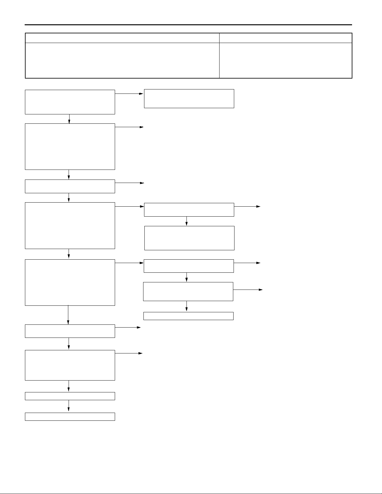
13A-32
MPI <4G1> -
Troubleshooting
Code No. P0403 EGR control solenoid valve system Probable cause
Range of Check
D Ignition switch: ON
D Battery voltage is 10 V or more.
Set Conditions
D The solenoid coil surge voltage (battery voltage + 2 V) is not detected when
the EGR control solenoid valve is turned from on to off.
D Malfunction of the EGR control solenoid valve
D Open or short circuit in the EGR control solenoid
valve circuit or loose connector contact
D Malfunction of engine-ECU
MUT-IIActuator Test
10 EGR control solenoid valve
OK:
Operating sound can be
heard and the valve vibrates.
NG
Measure at the EGR control solenoid
valve connector A-88.
D Disconnect the connector, and
measure at the solenoid valve
side.
D The resistance between terminals
1 and 2
OK:
28 - 36 W (at 20_C)
OK
Check the following connector:
A-88
OK
Measure at the EGR control solenoid
valve connector A-88.
D Disconnect the connector and
measure at the harness side.
D Ignition switch: ON
D The voltage between terminal 1
and earth
OK:
System voltage
OK
Measure at engine-ECU connector
B-37.
D Measure the voltage at the
engine-ECU terminal.
D Ignition switch: ON
D The voltage between terminal 6
and earth
OK:
System voltage
OK
Check the following connectors:
B-13, B-37
OK
Check the harness wires between
the EGR control solenoid valve and
the engine control relay, and
between the EGR control solenoid
valve and the engine-ECU.
OK
OK
NG
NG
NG
NG
NG
NG
Intermittent malfunction
(Refer to GROUP 00 - Points to
Note for Intermittent Malfunctions.)
Replace
Repair
Check the following connector:
B-13
NG
Check the harness wire between the
EGR control solenoid valve and the
engine control relay, and repair if
necessary.
Check the following connector:
B-37
OK
Check the harness wire between the
EGR control solenoid valve and the
engine-ECU.
OK
Replace the engine-ECU.
Repair
Repair
NG
NG
NG
Repair
Repair
Repair
Check the trouble symptoms.
NG
Replace the engine-ECU.
Page 63
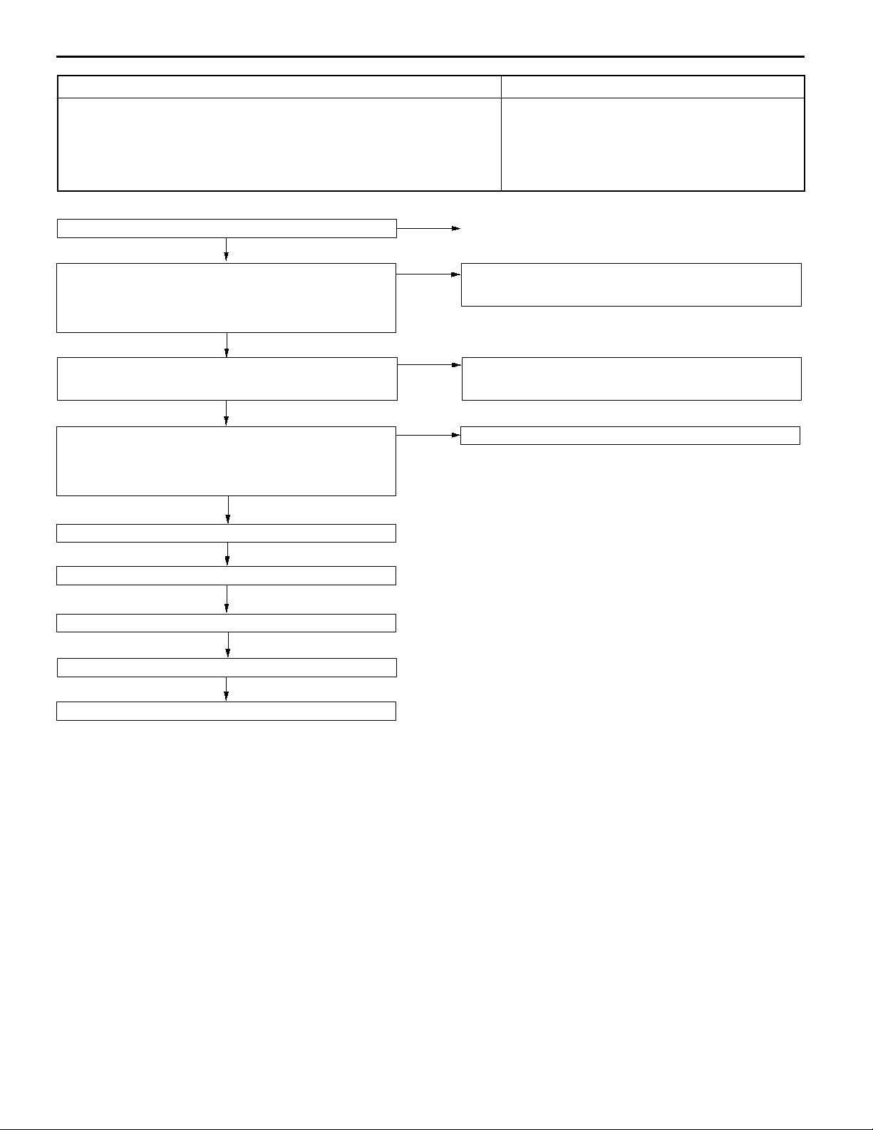
MPI <4G1> -
Troubleshooting
Code No. P0421 Catalyst malfunction Probable cause
Range of Check
D The engine speed is 4,000 r/min or less.
D During driving
D During air/fuel ratio feedback control
Set Conditions
D The ratio between the oxygen sensor (rear) and the oxygen sensor (front)
output frequencies reaches 0.8 per 10 seconds on average.
D Malfunction of catalyst
D Malfunction of the oxygen sensor (front)
D Malfunction of the oxygen sensor (rear)
D Malfunction of engine-ECU
13A-33
Check the exhaust manifold. (Are there any cracks?)
OK
MUT-IIData list
59 Oxygen sensor (rear)
D Transmission: 2nd
D Drive with wide open throttle
OK:
600 - 1,000 mV
OK
MUT-IIData list
11 Oxygen sensor (front)
OK:
600 - 1,000 mV when racing suddenly
OK
MUT-IIData list
11 Oxygen sensor (front)
D Transmission: 2nd
OK:
Changeover between 0 - 400 mV and 600 - 1,000
mV occur 15 times in 10 seconds.
OK
Replace the oxygen sensor (rear).
Check the trouble symptoms.
NG
Replace the catalytic converter.
NG
NG
NG
NG
Repair
Check the oxygen sensor (rear) system <sensor 2>
(Refer to P.13A-22, INSPECTION PROCEDURE FOR
DIAGNOSTIC TROUBLE CODE P0136.)
Check the oxygen sensor (front) system <sensor 1>
(Refer to P.13A-19, INSPECTION PROCEDURE FOR
DIAGNOSTIC TROUBLE CODE P0130.)
Replace the oxygen sensor (front).
Check the trouble symptoms.
Replace the engine-ECU.
NG
Page 64
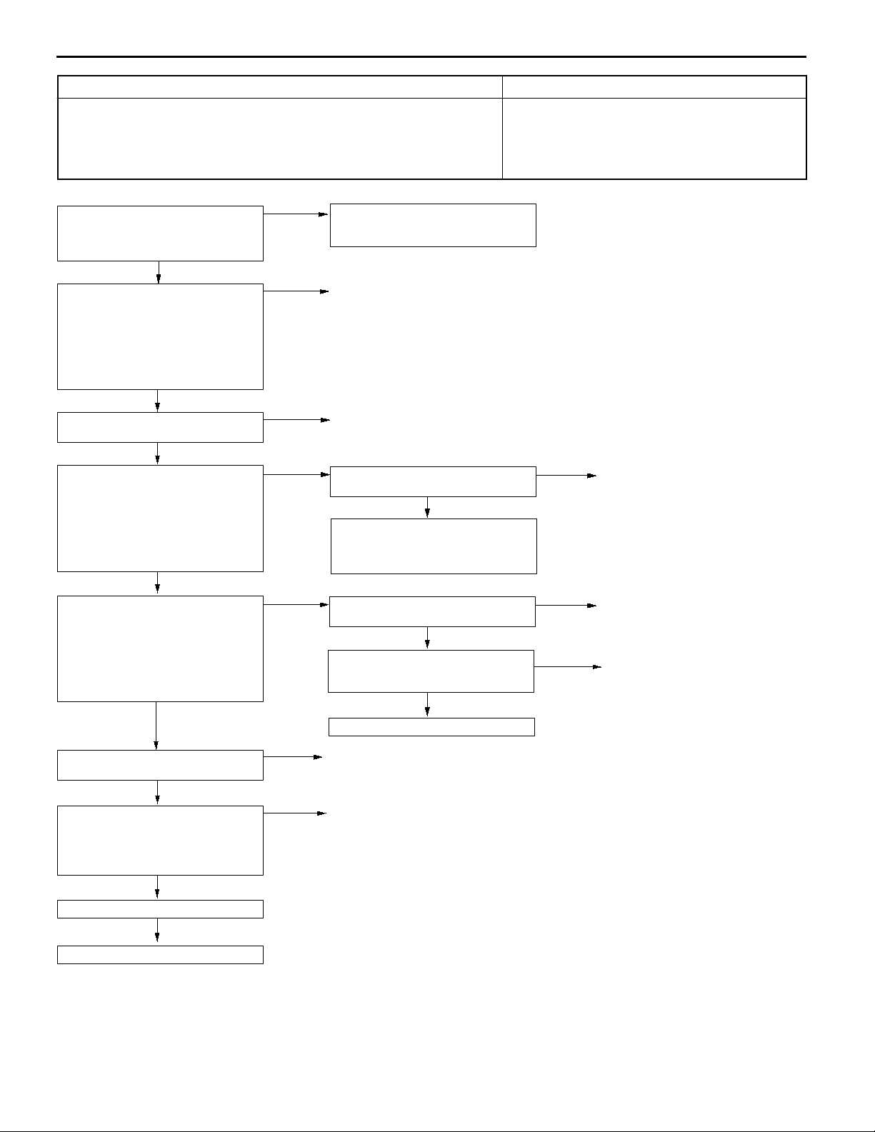
13A-34
MPI <4G1> -
Troubleshooting
Code No. P0443 Purge control solenoid valve system Probable cause
Range of Check
D Ignition switch: ON
D Battery voltage is 10 V or more.
Set Conditions
D The solenoid coil surge voltage (battery voltage + 2 V) is not detected when
the purge control solenoid valve is turned from on to off.
D Malfunction of the purge control solenoid valve
D Open or short circuit in the purge control solenoid
valve circuit or loose connector contact
D Malfunction of engine-ECU
MUT-IIActuator Test
08 Purge control solenoid valve
OK:
Operating sound can be
heard and the valve vibrates.
NG
Measure at the purge control
solenoid valve connector A-81.
D Disconnect the connector, and
measure at the solenoid valve
side.
D The resistance between terminals
1 and 2
OK:
28 - 36 W (at 20_C)
OK
Check the following connector:
A-81
OK
Measure at the purge control
solenoid valve connector A-81.
D Disconnect the connector and
measure at the harness side.
D Ignition switch: ON
D The voltage between terminal 2
and earth
OK:
System voltage
OK
Measure at engine-ECU connector
B-37.
D Measure the voltage at the
engine-ECU terminal.
D Ignition switch: ON
D The voltage between terminal 9
and earth
OK:
System voltage
OK
Check the following connectors:
B-13, B-37
OK
Check the harness wires between
the purge control solenoid valve and
the engine control relay, and
between the purge control solenoid
valve and the engine-ECU.
OK
OK
NG
NG
NG
NG
NG
NG
Intermittent malfunction
(Refer to GROUP 00 - Points to
Note for Intermittent Malfunctions.)
Replace
Repair
Check the following connector:
B-13
NG
Check the harness wire between the
purge control solenoid valve and the
engine control relay, and repair if
necessary.
Check the following connector:
B-37
OK
Check the harness wire between the
purge control solenoid valve and the
engine-ECU.
OK
Replace the engine-ECU.
Repair
Repair
NG
NG
NG
Repair
Repair
Repair
Check the trouble symptoms.
NG
Replace the engine-ECU.
Page 65
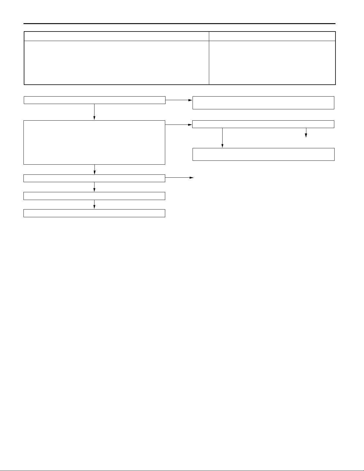
MPI <4G1> -
Troubleshooting
Code No. P0500 Vehicle speed sensor system Probable cause
Range of Check
D Engine: Two seconds after the engine was started
D Idle switch: OFF
D Engine speed: 2,500 r/min or more
D During high engine load
Set Conditions
D The sensor output voltage does not change for 2 seconds (no pulse signal
input).
D Malfunction of the vehicle speed sensor
D Open or short circuit in the vehicle speed sensor
circuit or loose connector contact
D Malfunction of engine-ECU
13A-35
Does the speedometer operate normally?
YES
Use an analyzer to measure the output waveform of the
vehicle speed sensor at engine-ECU connector B-34.
D Driving the vehicle
D The voltage between terminal 86 and earth
OK:
A normal waveform should be displayed as described
in OSCILLOSCOPE INSPECTION PROCEDURE,
and noise should not be displayed in the waveform.
(Refer to GROUP 23 - Troubleshooting.)
OK
Check the following connector:
Check the trouble symptoms.
Replace the engine-ECU.
B-34
OK
NG
NO
NG
NG
Check the vehicle speed sensor
(Refer to GROUP 54 - Combination Meter.)
Check the following connectors:
OK
Check the harness wire between intermediate connector B-33
and the engine-ECU, and repair if necessary.
Repair
B-33, B-34
NG
Repair
Page 66

13A-36
MPI <4G1> -
Troubleshooting
Code No. P0505 Idle speed control (ISC) system Probable cause
Check Area
D Vehicle speed has reached 1.5 km/h at least once.
D Under the closed loop idle speed control.
Judgment Criteria
D Actual idle speed has continued to be higher than the target idle speed by
300 r/min or more for 10 sec.
Check Area
D Vehicle speed has reached 1.5 km/h at least once.
D During idle speed closed loop control.
D The highest temperature at the last drive is 45_C or less.
D Engine coolant temperature is approx. 80_C or more.
D Battery voltage is 10 V or more.
D Intake air temperature is - 10_C (14_F) or more.
Judgment Criteria
D Actual idle speed has been minimum 200 r/min higher than the target idle
speed for ten seconds.
Check Area
D During idle speed closed loop control.
D Engine coolant temperature is about 80_C or higher.
D Battery voltage is 10 V or higher.
D Power steering switch is off.
D Intake air pipe pressure is 53 kPa or less.
D Intake air temperature is - 10_C or more.
Judgment Criteria
D Actual idle speed has been minimum 100 r/min higher than the target idle
speed for ten seconds.
D Malfunction of idle speed control (ISC) servo
D Improper connector contact, open circuit or
short-circuited harness wire
D Malfunction of the engine-ECU
Page 67
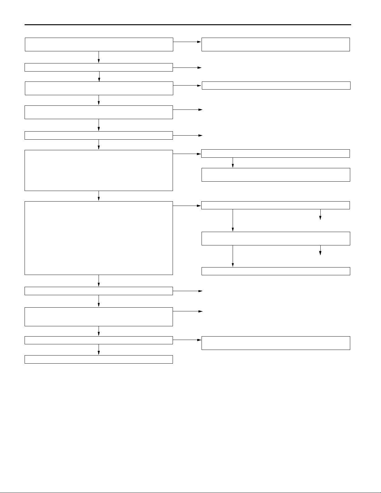
MPI <4G1> -
Troubleshooting
13A-37
MUT-IISelf-Diag Code
Is any diagnosis code other than No. P0505 output?
NO
Check intake air hose and intake manifold for air intake.
OK
contamination.
OK
Check the idle speed control (ISC) servo.
(Refer to P.13A-88*.)
OK
Check the following connector:
Measure at the idle speed control servo connector A-56.
D Disconnect the connector, and measure at the harness
side.
D Ignition switch: ON
D The voltage between terminal 2 and earth
D The voltage between terminal 5 and earth
OK:
System voltage
Measure at engine-ECU connector B-37.
D Connect the connector using test harness (MB991709),
and measure at pick-up harness.
D The voltage between terminal 4 and earth
D The voltage between terminal 5 and earth
D The voltage between terminal 17 and earth
D The voltage between terminal 18 and earth
OK:
The voltage changes as follows for three seconds
when the ignition switch is turned ON.
(When using a circuit tester)
5 V and 8 V alternates
(When using an analyzer)
1 V or less and system voltage alternates
Check the following connectors:
Check the harness wire between the engine control relay and
the idle speed control servo, and between the idle speed
control servo and the engine-ECU.
Check the trouble symptoms.
A-56
OK
OK
OK
B-13, B-37
OK
OK
NG
YES
NG
NG
NG
NG
NG
NG
NG
NG
OK
Refer to P.13A-9, INSPECTION CHART FOR DIAGNOSIS
CODES.
Repair
Clean around the throttle valve. (Refer to P.13A-75*.)Check the throttle body (around the throttle valve) for
Replace
Repair
Check the following connector:
OK
Check the harness wire between the engine control relay and
the idle speed control servo, and repair if necessary.
Check the following connector:
OK
Check the harness wire between the idle speed control servo
and the engine-ECU.
OK
Replace the engine-ECU.
Repair
Repair
Intermittent malfunction (Refer to GROUP 00 - Points to Note
for Intermittent Malfunctions.)
B-13
B-37
NG
Repair
NG
Repair
Replace the engine-ECU.
NOTE:
*: Refer to the ’96 COLT/LANCER Workshop Manual (Pub. No. PWME9511).
Page 68

13A-38
MPI <4G1> -
Troubleshooting
Code No. P1610 Immobilizer system Probable cause
Range of Check
D Ignition switch: ON
Set Conditions
D Improper communication between the engine-ECU and the immobilizer-ECU
D Open or short circuit, or loose connector contact
D Malfunction of the immobilizer-ECU
D Malfunction of the engine-ECU
NOTE
(1) If the registered ignition keys are close each other when starting the engine, radio interference may
cause this code to be displayed.
(2) This code may be displayed when registering the key ID code.
Check the following connectors:
B-24, B-32, B-35
OK
Check the harness wire between the
immobilizer-ECU and the
engine-ECU.
OK
Check the trouble symptoms.
NG
Replace the immobilizer-ECU.
NG
NG
Repair
Replace
Check the trouble symptoms.
NG
Replace the engine-ECU.
Page 69

MPI <4G1> -
Troubleshooting
INSPECTION CHART FOR TROUBLE SYMPTOMS
13A-39
Trouble symptom Inspection
procedure
No.
Communication Communication with all systems is not possible. 1 13A-40
with MUT-II is
impossible.
Engine warning
lamp and
related parts
Starting No initial combustion (starting impossible) 5 13A-42
Idling stability Unstable idling (Rough idling, hunting) 8 13A-45
(Improper idling)
Idling stability When the engine is cold, it stalls at idling. (Die out) 11 13A-48
(Engine stalls)
Communication with engine-ECU only is not possible. 2 13A-40
The engine warning lamp does not illuminate right after the
ignition switch is turned to the ON position.
The engine warning lamp remains illuminating and never goes
out.
Initial combustion but no complete combustion
(starting impossible)
Long time to start (improper starting) 7 13A-44
Idling speed is high. (Improper idling speed) 9 13A-47
Idling speed is low. (Improper idling speed) 10 13A-47
When the engine becomes hot, it stalls at idling. (Die out) 12 13A-49
3 13A-41
4 13A-41
6 13A-43
Reference page
The engine stalls when starting the car. (Pass out) 13 13A-51
The engine stalls when decelerating. 14 13A-51
Driving Hesitation, sag or stumble 15 13A-52
The feeling of impact or vibration when accelerating 16 13A-53
The feeling of impact or vibration when decelerating 17 13A-53
Poor acceleration 18 13A-54
Surge 19 13A-55
Knocking 20 13A-56
Dieseling 21 13A-56
Too high CO and HC concentration when idling 22 13A-57
Fans (radiator fan, A/C condenser fan) are inoperative 23 13A-58
Page 70

13A-40
MPI <4G1> -
Troubleshooting
INSPECTION PROCEDURE FOR TROUBLE SYMPTOMS
INSPECTION PROCEDURE 1
Communication with MUT-IIis not possible.
(Communication with all systems is not possible.)
The cause is probably a defect in the power supply system (including earth) for the
diagnosis line.
Measure at the diagnosis connector
(16-pin) B-18.
D Voltage between 16 and earth
OK:
Battery voltage
OK
Measure at the diagnosis connector
(16-pin) B-18.
D Continuity between 4 and earth
D Continuity between 5 and earth
OK:
Continuity
OK
Replace the MUT-II.
NG
NG
Check the following connectors:
B-67, B-74
OK
check the trouble symptom.
Check the harness wire between the
diagnostic connector (16-pin) and earth,
and repair if necessary.
INSPECTION PROCEDURE 2
MUT-IIcommunication with engine-ECU is impossible.
One of the following causes may be suspected:
D No power supply to engine-ECU.
D Defective earth circuit of engine-ECU.
D Defective engine-ECU.
D Improper communication line between engine-ECU and MUT-II
Probable cause
D Malfunction of the connector
D Malfunction of the harness wire
NG
NG
Repair
Check the harness wire between the
power supply and diagnostic connector
(16-pin), and repair if necessary.
Probable cause
D Malfunction of engine-ECU power supply circuit
D Malfunction of engine-ECU
D Open circuit between engine-ECU and diagnosis
connector
Check the following connectors:
B-24 <Vehicles with immobilizer system>, B-32, B-35, B-38
OK
check the trouble symptom.
NG
Check the harness wire between engine-ECU and diagnosis connector.
NG
Repair
NG
OK
Repair
Check the harness wire
between engine-ECU and
earth.
OK
Check the power supply and ignition switch-IG system.
(Refer to P.13A-59, INSPECTION PROCEDURE 25.)
NG
Repair
NOTE
Though the above inspection has been performed, if trouble symptom does not disappear, check the
multi center display, and replace it if necessary.
Page 71

INSPECTION PROCEDURE 3
MPI <4G1> -
Troubleshooting
13A-41
The engine warning lamp does not illuminate right after
the ignition switch is turned to the ON position.
Because there is a burnt-out bulb, the engine-ECU causes the engine warning lamp
to illuminate for five seconds immediately after the ignition switch is turned to ON.
If the engine warning lamp does not illuminate immediately after the ignition switch
is turned to ON, one of the malfunctions listed at right has probably occurred.
MUT-IIData list
16 Engine ECU power supply voltage (Refer to P.13A-66.)
OK
Measure at the engine-ECU connector B-36.
D Disconnect the connector, and measure at the harness side.
D Earth the terminal No. 36.
OK:
The engine warning lamp illuminates.
NG
Check a burnt-out bulb.
OK
Measure at the combination meter connector B-02.
D Disconnect the connector, and measure at the harness side.
D Voltage between 42 and earth (Ignition switch: ON)
OK:
System voltage
OK
Check the following connectors:
B-02, B-32, B-36, B-69
OK
check the trouble symptom.
NG
Replace
NG
OK
NG
NG
NG
Check the engine-ECU power supply and earth circuit.
(Refer to P.13A-59, INSPECTION PROCEDURE 24.)
Check the following
connector:
check the trouble symptom.
Replace the engine-ECU.
Check the engine warning lamp power supply circuit, and repair
if necessary.
Repair
Check the harness wire between combination meter and engineECU, and repair if necessary.
Probable cause
D Burnt-out bulb
D Defective warning lamp circuit
D Malfunction of the engine-ECU
NG
B-36.
OK
NG
Repair
INSPECTION PROCEDURE 4
The engine warning lamp remains illuminating and never
goes out.
In cases such as the above, the cause is probably that the engine-ECU is detecting
a problem in a sensor or actuator, or that one of the malfunctions listed at right has
occurred.
MUT-IISelf-Diag code
Are diagnosis codes displayed?
No
Measure at the combination meter connector B-02.
D Disconnect the connector, and measure at the harness side.
D Disconnect the engine-ECU connector
D Continuity between 53 and earth
OK:
No continuity
OK
Replace the engine-ECU.
Yes
NG
Probable cause
D Short-circuit between the engine warning lamp and
engine-ECU
D Malfunction of the engine-ECU
Refer to P.13A-9, INSPECTION CHART FOR DIAGNOSIS
CODES.
Check the harness wire between combination meter and engineECU connector, and repair if necessary.
Page 72
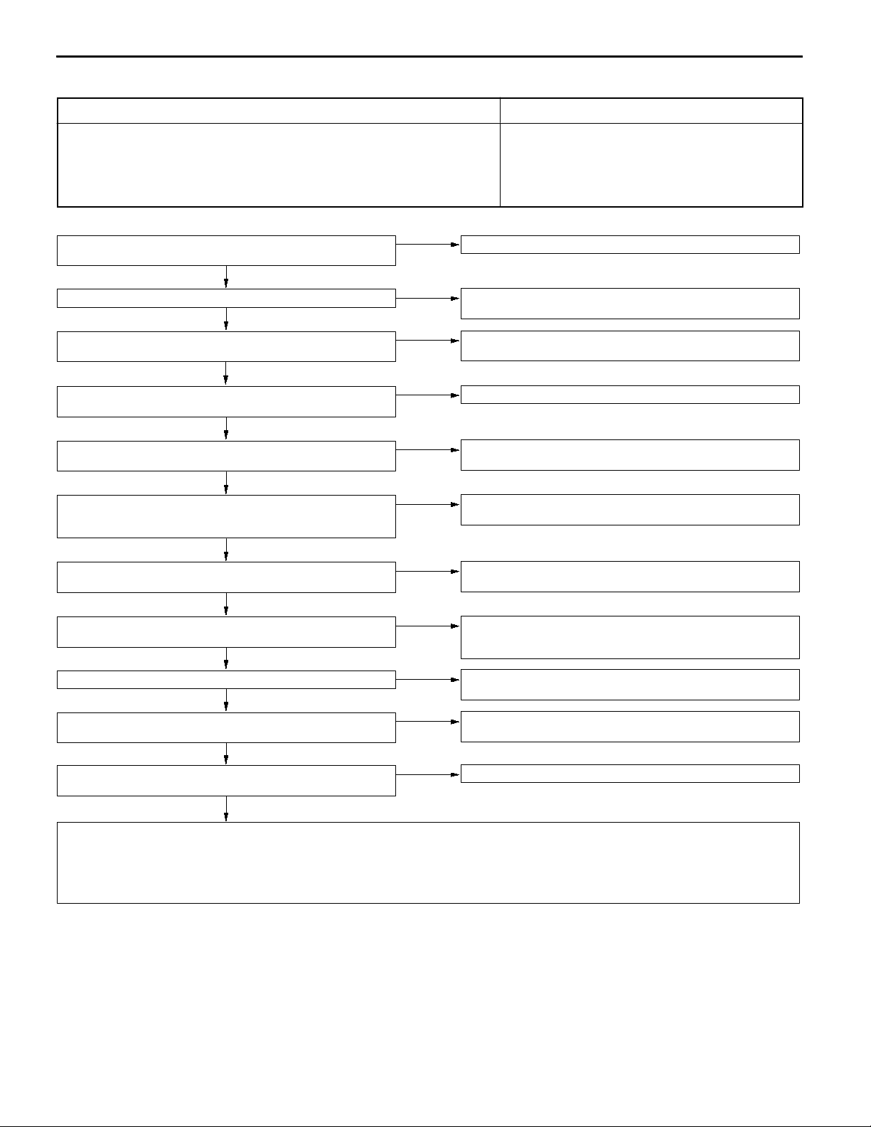
13A-42
INSPECTION PROCEDURE 5
MPI <4G1> -
Troubleshooting
No initial combustion (starting impossible)
In cases such as the above, the cause is probably that a spark plug is defective,
or that the supply of fuel to the combustion chamber is defective.
In addition, foreign materials (water, kerosene, etc.) may be mixed with the fuel.
Check battery voltage when cranking.
OK:
8 V or higher
OK
Is an immobilizer-ECU diagnosis code displayed?
No
MUT-IIData list
16 Voltage of engine-ECU power source (Refer to P.13A-66.)
OK
Does the camshaft rotate at the engine cranking? (When oil filler
cap is removed.)
Yes
MUT-IISelf-Diag code
Are diagnosis codes displayed?
No
MUT-IIData list
22 Crank angle sensor
OK:
Cranking speed is displayed.
OK
MUT-IIActuator test
07 Fuel pump (Refer to P.13A-70.)
OK
MUT-IIData list
21 Engine coolant temperature sensor (Refer to P.13A-66.)
OK
Can any sound be heard from the injectors when cranking?
OK
Does the engine tachometer display the cranking speed?
D Set the tachometer of primary voltage detection type.
OK
Check the ignition timing when cranking.
OK:
Approx. 5_ BTDC
OK
Check the following items.
D Check the ignition coil, spark plugs, spark plug cables. (Refer to GROUP 16 - On-vehicle service.)
D Check if the injectors are clogged.
D Check if foreign materials (water, alcohol, etc.) got into fuel.
D Check the compression pressure.
D Check the immobilizer system. (Refer to GROUP 54 - Ignition Key and Immobilizer.)
NG
Yes
NG
No
Yes
No
NG
NG
NG
NG
NG
Probable cause
D Malfunction of the ignition system
D Malfunction of the fuel pump system
D Malfunction of the injectors
D Malfunction of the engine-ECU
D Malfunction of the immobilizer system
D Foreign materials in fuel
Check the battery. (Refer to GROUP 54 - Battery.)
Check the immobilizer.
(Refer to GROUP 54 - Ignition Key and Immobilizer.)
Check the power supply and ignition switch-IG system.
(Refer to P.13A-59, INSPECTION PROCEDURE 25.)
Check timing belt for breakage.
Refer to P.13A-9, INSPECTION CHART FOR DIAGNOSIS
CODES.
Check thecrank angle sensor system. (Referto P.13A-29, INSPECTION PROCEDURE FOR DIAGNOSIS CODE P0335.)
Check the fuel pump system. (Refer to P.13A-60, INSPECTION
PROCEDURE 26.)
Check the engine coolant temperature sensor system. (Refer to
P.13A-13, INSPECTION PROCEDURE FOR DIAGNOSIS CODE
P0115.)
Check the injector system. (Refer to P.13A-26, INSPECTION PROCEDURE FOR DIAGNOSIS CODE P0201, P0202, P0203, P0204.)
Check the ignition circuit system.
(Refer to P.13A-63, INSPECTION PROCEDURE 30.)
Check that the distributor is installed properly.
Page 73

INSPECTION PROCEDURE 6
MPI <4G1> -
Troubleshooting
13A-43
Initial combustion but no complete combustion
(starting impossible)
In such cases as the above, the cause is probably that the spark plugs are generating
sparks but the sparks are weak, or the initial mixture for starting is not appropriate.
Check battery voltage when cranking.
OK:
8 V or higher
OK
MUT-IISelf-Diag code
Are diagnosis codes displayed?
No
MUT-IIActuator test
07 Fuel pump (Refer to P.13A-70.)
OK
MUT-IIData list
21 Engine coolant temperature sensor (Refer to P.13A-66.)
OK
MUT-IIData list
18 Ignition switch-ST (Refer to P.13A-66.)
OK
Can any sound be heard from the injectors when cranking?
OK
Is starting good if the engine is cranked with the accelerator pedal
slightly depressed?
No
NG
Yes
NG
NG
NG
NG
Yes
Check the battery. (Refer to GROUP 54 - Battery.)
Refer to P.13A-9, INSPECTION CHART FOR DIAGNOSIS
CODES.
Check the fuel pump system.
(Refer to P.13A-60, INSPECTION PROCEDURE 26.)
Check the engine coolant temperature sensor system.
(Refer to P.13A-13, INSPECTION PROCEDURE FOR DIAGNOSIS
CODE P0115.)
Check the ignition switch-ST system.
(Refer to P.13A-61, INSPECTION PROCEDURE 27.)
Check the injector system. (Refer to P.13A-26, INSPECTION PROCEDURE FOR DIAGNOSIS CODE P0201, P0202, P0203, P0204.)
Check ISC servo for
operation sound.
(Refer to P.13A-88*.)
D Clean the throttle valve area. (Refer to P.13A-75*.)
Probable cause
D Malfunction of the ignition system
D Malfunction of the injector system
D Foreign materials in fuel
D Poor compression
D Malfunction of the engine-ECU
NG
Check the ISC servo system.
(Refer to P.13A-36, INSPECTION PROCEDURE FOR
OK
DIAGNOSIS CODE P0505.)
Check the ignition timing when cranking.
OK:
Approx. 5_BTDC
OK
Check the following items.
D Check the ignition coil, spark plugs, spark plug cables. (Refer to GROUP 16 - On-vehicle Service.)
D Check if the injectors are clogged.
D Check the compression pressure. (Refer to GROUP 11B - On-vehicle Service.)
D Check fuel lines for clogging.
D Check if foreign materials (water, alcohol, etc.) got into fuel.
NG
Check that the distributor is installed properly.
NOTE:
*: Refer to the ’96 COLT/LANCER Workshop Manual (Pub. No. PWME9511).
Page 74

13A-44
INSPECTION PROCEDURE 7
MPI <4G1> -
Troubleshooting
In takes too long time to start. (Incorrect starting)
In cases such as the above, the cause is probably that the spark is weak and ignition
is difficult, the initial mixture for starting is not appropriate, or sufficient compression
pressure is not being obtained.
Check battery voltage when cranking
OK:
8 V or higher
OK
MUT-IISelf-Diag code
Are diagnosis codes displayed?
No
MUT-IIActuator test
07 Fuel pump (Refer to P.13A-70.)
OK
MUT-IIData list
21 Engine coolant temperature sensor (Refer to P.13A-66.)
OK
MUT-IIData list
18 Ignition switch-ST (Refer to P.13A-66.)
OK
Can any sound be heard from the injectors when cranking?
OK
Check the ignition timing when cranking.
OK:
Approx. 5_BTDC
OK
NG
Yes
NG
NG
NG
NG
NG
Check the battery. (Refer to GROUP 54 - Battery.)
Refer to P.13A-9, INSPECTION CHART FOR DIAGNOSIS
CODES.
Check the fuel pump system.
(Refer to P.13A-60, INSPECTION PROCEDURE 26.)
Check the engine coolant temperature sensor system.
(Refer to P.13A-13, INSPECTION PROCEDURE FOR DIAGNOSIS
CODE P0115.)
Check the ignition switch-ST system.
(Refer to P.13A-61, INSPECTION PROCEDURE 27.)
Check the injector system. (Refer to P.13A-26, INSPECTION PROCEDURE FOR DIAGNOSIS CODE P0201, P0202, P0203, P0204.)
Check that the distributor is installed properly.
Probable cause
D Malfunction of the ignition system
D Malfunction of the injector system
D Inappropriate gasoline use
D Poor compression
Check the following items.
D Check the ignition coil, spark plugs, spark plug cables. (Refer to GROUP 16 - On-vehicle Service.)
D Check if the injectors are clogged.
D Check the compression pressure. (Refer to GROUP 11B - On-vehicle Service.)
D Check if foreign materials (water, alcohol, etc.) got into fuel.
Page 75

INSPECTION PROCEDURE 8
MPI <4G1> -
Troubleshooting
13A-45
Unstable idling (Rough idling, hunting)
In cases as the above, the cause is probably that the ignition system, air/fuel mixture,
idle speed control (ISC) or compression pressure is defective.
Because the range of possible causes is broad, inspection is narrowed down to simple
items.
Were the battery terminals disconnected?
No
MUT-IISelf-Diag code
Are diagnosis codes displayed?
No
Does idling speed fluctuate excessively?
No
Check the ISC servo for operation sound. (Refer to P.13A-88*.)
OK
Check the injector for operation sound.
OK
MUT-IIData list
14 Throttle position sensor (Refer to P.13A-65.)
OK
MUT-IIData list
13 Intake air temperature sensor (Refer to P.13A-65.)
OK
MUT-IIData list
21 Engine coolant temperature sensor (Refer to P.13A-66.)
OK
MUT-IIActuator test
08 Purge control solenoid valve (Refer to P.13A-70.)
OK
MUT-IIActuator test
10 EGR control solenoid valve (Refer to P.13A-70.)
OK
MUT-IIData list
59 Oxygen sensor (rear)
D Transmission: 2nd gear
D Driving with throttle widely open
OK:
600 - 1,000 mV
OK
MUT-IIData list
11 Oxygen sensor (front)
OK:
600 - 1,000 mV during sudden racing
Yes
Yes
Yes
NG
NG
NG
NG
NG
NG
NG
NG
NG
OK
After warming-up, let the engine run at idling for 10 minutes.
Refer to P.13A-9, INSPECTION CHART FOR DIAGNOSIS
CODES.
Check the throttle body. (Refer to P.13A-75*.)
check the trouble symptom.
Inspect the intake of air into the air intake system.
D Broken intake manifold gasket
D Broken air intake hose
D Broken vacuum hose
D Positive crankcase ventilation valve does not operate.
Check the ISC system. (Refer to P.13A-36, INSPECTION PROCEDURE FOR DIAGNOSIS CODE P0505.)
Check the injector system. (Refer to P.13A-26, INSPECTION PROCEDURE FOR DIAGNOSIS CODE P0201, P0202, P0203, P0204.)
Check the throttle position sensor system. (Refer to P.13A-16, INSPECTION PROCEDURE FOR DIAGNOSIS CODE P0120.)
Check the intake air temperature sensor system.
(Refer to P.13A-12, INSPECTION PROCEDURE FOR DIAGNOSIS
CODE P0110.)
Check the engine coolant temperature sensor system.
(Refer to P.13A-13, INSPECTION PROCEDURE FOR DIAGNOSIS
CODE P0115.)
Check the purge control solenoid valve system. (Refer to P.13A-34,
INSPECTION PROCEDURE FOR DIAGNOSIS CODE P0443.)
Check the EGR control solenoid valve system. (Refer to P.13A-32,
INSPECTION PROCEDURE FOR DIAGNOSIS CODE P0403.)
Check the oxygen sensor (rear) system. (Refer to P.13A-22, INSPECTION PROCEDURE FOR DIAGNOSIS CODE P0136.)
Check the oxygen sensor (front) system. (Refer to P.13A-19, INSPECTION PROCEDURE FOR DIAGNOSIS CODE P0130.)
To next page
Probable cause
D Malfunction of the ignition system
D Malfunction of air-fuel ratio control system
D Malfunction of the ISC system
D Malfunction of the purge control solenoid valve system
D Malfunction of the EGR solenoid valve system
D Poor compression
D Drawing air into exhaust system
NG
NOTE:
*: Refer to the ’96 COLT/LANCER Workshop Manual (Pub. No. PWME9511).
Page 76
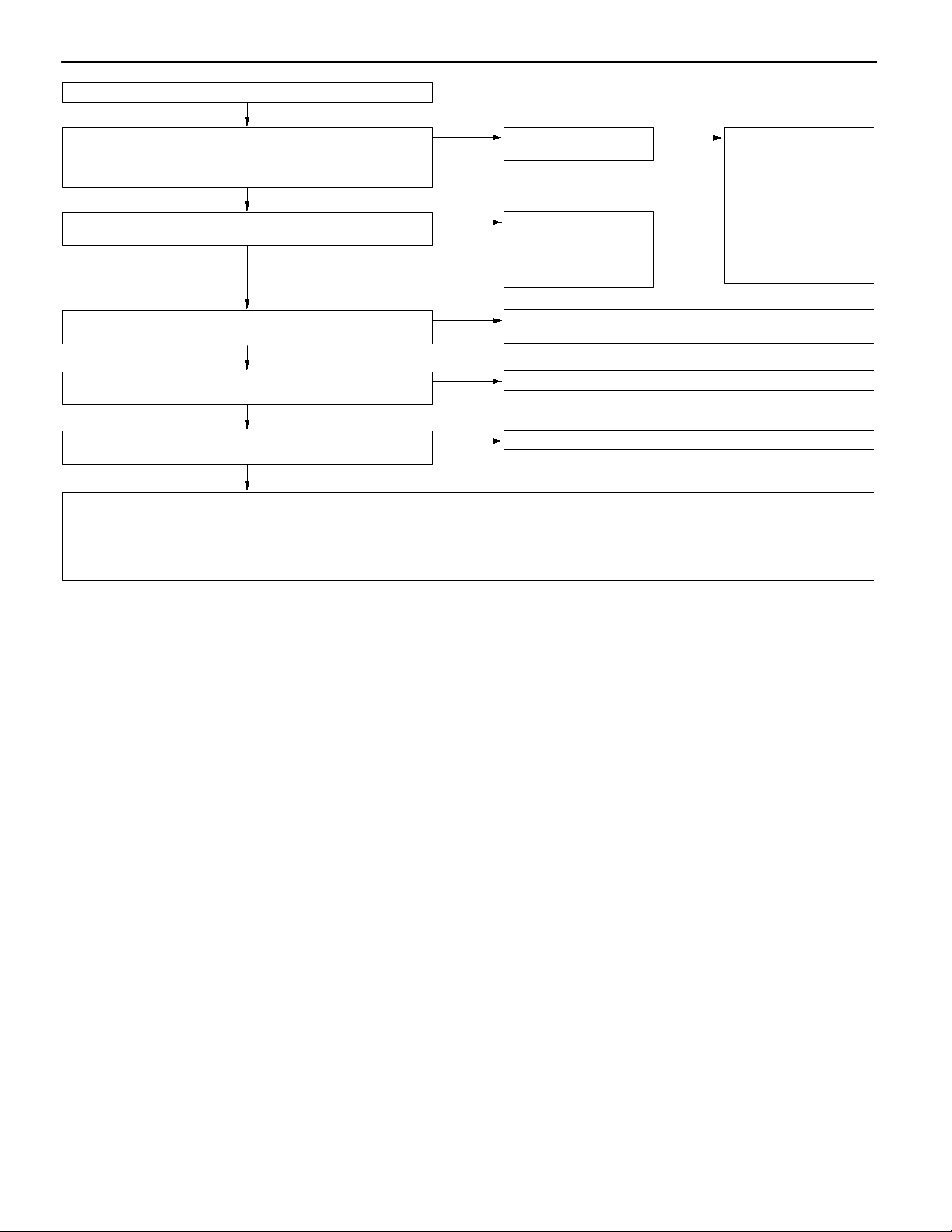
13A-46
From previous page
OK
MUT-IIData list
11 Oxygen sensor (front)
OK:
Changes between 0 - 400 mV and 600 - 1,000 mV during
idling
OK
MUT-IIData list
27 Power steering fluid pressure switch (Refer to P.13A-67.)
OK
MPI <4G1> -
Troubleshooting
NG
NG
Check the fuel pressure.
(Refer to P.13A-78*.)
Check the power steering
fluid pressure switch system. (Refer to P.13A-61,
INSPECTION PROCEDURE 28.)
OK
1. Inspect the intake of
air into the air intake
system.
D Broken intake man-
ifold gasket
D Broken vacuum hose
D PCV valve does not
operate.
D Broken airintake hose
2. Check the injector for
clog.
MUT-IIData list
28 A/C switch (Refer to P.13A-67.)
OK
MUT-IIData list
45 ISC servo position (Refer to P.13A-68.)
OK
Check the ignition timing.
(Refer to GROUP 11B - On-vehicle Service.)
OK
Check the following items.
D Check the ignition coil, spark plugs, spark plug cables. (Refer to GROUP 16 - On-vehicle Service.)
D Check the purge control system. (Refer to GROUP 17 - Emission Control System.)
D Check the EGR control system. (Refer to GROUP 17 - Emission Control System.)
D Check the compression pressure. (Refer to GROUP 11A - On-vehicle Service.)
D Check if foreign materials (water, alcohol, etc.) got into fuel.
NG
NG
NG
Check the A/C switch and A/C relay system.
(Refer to P.13A-62, INSPECTION PROCEDURE 29.)
Adjust the basic idle speed. (Refer to P.13A-78.)
Check that the distributor is installed properly.
NOTE:
*: Refer to the ’96 COLT/LANCER Workshop Manual (Pub. No. PWME9511).
Page 77
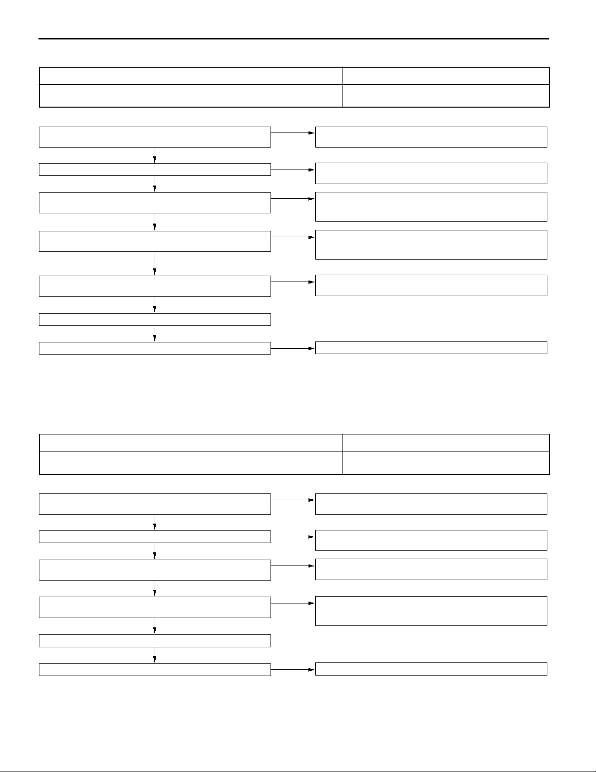
INSPECTION PROCEDURE 9
MPI <4G1> -
Troubleshooting
13A-47
Idling speed is high. (Improper idling speed)
In such cases as the above, the cause is probably that the intake air volume during
idling is too great.
MUT-IISelf-Diag code
Are diagnosis codes displayed?
No
Check the ISC servo for operation sound. (Refer to P.13A-88*.)
OK
MUT-IIData list
14 Throttle position sensor (Refer to P.13A-65.)
OK
MUT-IIData list
21 Engine coolant temperature sensor (Refer to P.13A-66.)
OK
MUT-IIData list
28 A/C switch (Refer to P.13A-67.)
OK
Basic idle adjustment (Refer to P.13A-78.)
check the trouble symptom.
Yes
NG
NG
NG
NG
NG
Refer to P.13A-9, INSPECTION CHART FOR DIAGNOSIS
CODES.
Check the ISC system. (Refer to P.13A-36, INSPECTION PROCEDURE FOR DIAGNOSIS CODE P0505.)
Check the throttle position sensor system.
(Refer to P.13A-16, INSPECTION PROCEDURE FOR DIAGNOSIS
CODE P0120.)
Check the engine coolant temperature sensor system.
(Refer to P.13A-13, INSPECTION PROCEDURE FOR DIAGNOSIS
CODE P0115.)
Check the A/C switch and A/C relay system.
(Refer to P.13A-62, INSPECTION PROCEDURE 29.)
Clean the throttle valve area. (Refer to P.13A-75*.)
Probable cause
D Malfunction of the ISC system
D Malfunction of the throttle body
NOTE:
*: Refer to the ’96 COLT/LANCER Workshop Manual (Pub. No. PWME9511).
INSPECTION PROCEDURE 10
Idling speed is low. (Improper idling speed)
In cases such as the above, the cause is probably that the intake air volume during
idling is too small.
MUT-IISelf-Diag code
Are diagnosis codes displayed?
No
Check the ISC servo for operation sound. (Refer to P.13A-88*.)
OK
MUT-IIData list
14 Throttle position sensor (Refer to P.13A-65.)
OK
MUT-IIData list
21 Engine coolant temperature sensor (Refer to P.13A-66.)
OK
Basic idle adjustment (Refer to P.13A-78.)
Yes
NG
NG
NG
Probable cause
D Malfunction of the ISC system
D Malfunction of the throttle body
Refer to P.13A-9, INSPECTION CHART FOR DIAGNOSIS
CODES.
Check the ISC system. (Refer to P.13A-36, INSPECTION PROCEDURE FOR DIAGNOSIS CODE P0505.)
Check the throttle position sensor system. (Refer to P.13A-16, INSPECTION PROCEDURE FOR DIAGNOSIS CODE P0120.)
Check the engine coolant temperature sensor system.
(Refer to P.13A-13, INSPECTION PROCEDURE FOR DIAGNOSIS
CODE P0115.)
check the trouble symptom.
NG
Clean the throttle valve area. (Refer to P.13A-75*.)
NOTE:
*: Refer to the ’96 COLT/LANCER Workshop Manual (Pub. No. PWME9511).
Page 78
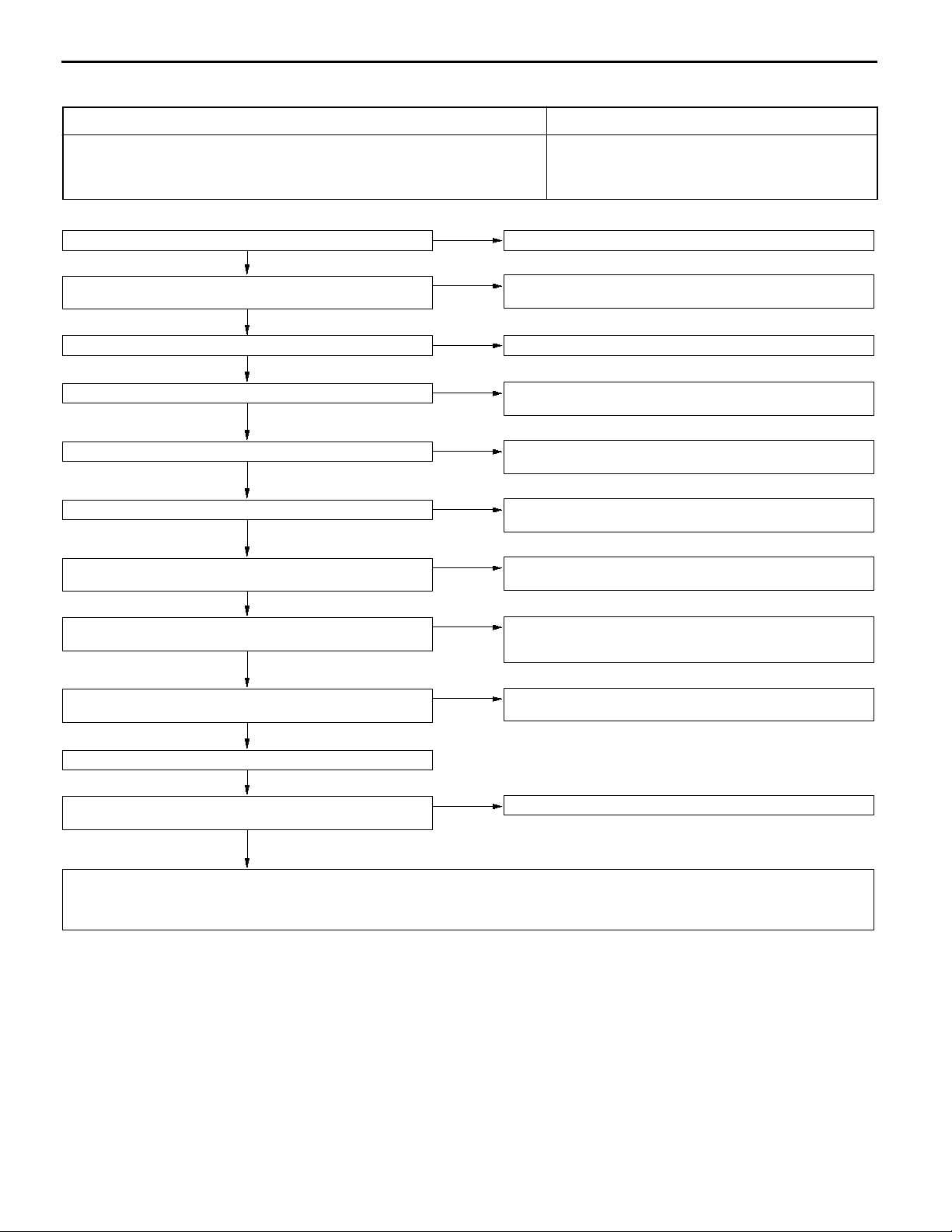
13A-48
INSPECTION PROCEDURE 11
MPI <4G1> -
Troubleshooting
When the engine is cold, it stalls at idling. (Die out)
In such cases as the above, thecause isprobably thatthe air/fuelmixture is inappropriate
when the engine is cold, or that the intake air volume is insufficient.
Were the battery terminals disconnected?
No
MUT-IISelf-Diag code
Are diagnosis codes displayed?
No
Does the engine stall right after the accelerator pedal is released?
No
Is engine-idling stable after the warming-up?
Yes
Check the ISC servo for operation sound. (Refer to P.13A-88*.)
OK
Check the injector for operation sound.
OK
MUT-IIData list
14 Throttle position sensor (Refer to P.13A-65.)
OK
MUT-IIData list
21 Engine coolant temperature sensor (Refer to P.13A-66.)
OK
MUT-IIActuator test
10 EGR control solenoid valve (Refer to P.13A-70.)
OK
Yes
Yes
Yes
No
NG
NG
NG
NG
NG
After warming-up, let the engine run at idling for 10 minutes.
Refer to P.13A-9, INSPECTION CHART FOR DIAGNOSIS
CODES.
Clean the throttle valve area. (Refer to P.13A-75*.)
Check if the unstable idling (Rough idling, hunting).
(Refer to P.13A-45, INSPECTION PROCEDURE 8.)
Check the ISC system. (Refer to P.13A-36, INSPECTION PROCEDURE FOR DIAGNOSIS CODE P0505.)
Check the injector system. (Refer to P.13A-26, INSPECTION PROCEDURE FOR DIAGNOSIS CODE P0201, P0202, P0203, P0204.)
Check the throttle position sensor system. (Refer to P.13A-16, INSPECTION PROCEDURE FOR DIAGNOSIS CODE P0120.)
Check the engine coolant temperature sensor system.
(Refer to P.13A-13, INSPECTION PROCEDURE FOR DIAGNOSIS
CODE P0115.)
Check the EGR control solenoid valve system. (Refer to P.13A-32,
INSPECTION PROCEDURE FOR DIAGNOSIS CODE P0403.)
Probable cause
D Malfunction of the ISC system
D Malfunction of the throttle body
D Malfunction of the injector system
D Malfunction of the ignition system
Check the fuel pressure. (Refer to P.13A-78*.)
OK
Check the ignition timing.
(Refer to GROUP 11B - On-vehicle Service.)
OK
Check the following items.
D Check the ignition coil, spark plugs, spark plug cables. (Refer to GROUP 16 - On-vehicle Service.)
D Check the compression pressure. (Refer to GROUP 11B - On-vehicle Service.)
D Check the engine oil viscosity.
NG
Check that the distributor is installed properly.
NOTE:
*: Refer to the ’96 COLT/LANCER Workshop Manual (Pub. No. PWME9511).
Page 79

INSPECTION PROCEDURE 12
MPI <4G1> -
Troubleshooting
13A-49
When the engine is hot, it stalls at idling. (Die out)
In such cases as the above, the cause is probably that ignition system, air/fuel mixture,
idle speed control (ISC) or compression pressure is defective.
In addition, if the engine suddenly stalls, the cause may also be a defective connector
contact.
Were the battery terminals disconnected?
No
MUT-IISelf-Diag code
Are diagnosis codes displayed?
No
Check the ISC servo for operation sound. (Refer to P.13A-88*.)
OK
Check the injector for operation sound.
OK
Does the engine stall right after the accelerator pedal is released?
No
Does the engine stall easily again?
Yes
Yes
Yes
NG
NG
Yes
No
After warming-up, let the engine run at idling for 10 minutes.
Refer to P.13A-9, INSPECTION CHART FOR DIAGNOSIS
CODES.
Check the ISC system. (Refer to P.13A-36, INSPECTION PROCEDURE FOR DIAGNOSIS CODE P0505.)
Check the injector system. (Refer to P.13A-26, INSPECTION PROCEDURE FOR DIAGNOSIS CODE P0201, P0202, P0203, P0204.)
Clean the throttle valve area. (Refer to P.13A-75*.)
While carrying out an intermittent malfunction simulation test (Refer
to GROUP 00 - Points to Note for Intermittent Malfunctions.), check
for sudden changes in the signals shown below.
D Crank angle sensor signal
D Injector drive signal
Probable cause
D Malfunction of the ignition system
D Malfunction of air-fuel ratio control system
D Malfunction of the ISC system
D Drawing air into intake system
D Improper connector contact
D Primary and secondary
ignition signal
D Fuel pump drive signal
D Engine ECU power supply
voltage
MUT-IIData list
14 Throttle position sensor (Refer to P.13A-65.)
OK
MUT-IIData list
13 Intake air temperature sensor (Refer to P.13A-65.)
OK
MUT-IIData list
21 Engine coolant temperature sensor (Refer to P.13A-66.)
OK
MUT-IIActuator test
10 EGR control solenoid valve (Refer to P.13A-70.)
OK
MUT-IIData list
59 Oxygen sensor (rear)
D Transmission: 2nd gear
D Driving with throttle widely open
OK:
600 - 1,000 mV
OK
MUT-IIData list
11 Oxygen sensor (front)
OK:
600 - 1,000 mV during sudden racing
OK
To next page
NG
NG
NG
NG
NG
NG
Check the throttle position sensor system. (Refer to P.13A-16, INSPECTION PROCEDURE FOR DIAGNOSIS CODE P0120.)
Check the intake air temperature sensor system.
(Refer to P.13A-12, INSPECTION PROCEDURE FOR DIAGNOSIS
CODE P0110.)
Check the engine coolant temperature sensor system.
(Refer to P.13A-13, INSPECTION PROCEDURE FOR DIAGNOSIS
CODE P0115.)
Check the EGR control solenoid valve system. (Refer to P.13A-32,
INSPECTION PROCEDURE FOR DIAGNOSIS CODE P0403.)
Check the oxygen sensor (rear) system. (Refer to P.13A-22, INSPECTION PROCEDURE FOR DIAGNOSIS CODE P0136.)
Check the oxygen sensor (front) system. (Refer to P.13A-19, INSPECTION PROCEDURE FOR DIAGNOSIS CODE P0130.)
Page 80

13A-50
From previous page
OK
MUT-IIData list
11 Oxygen sensor (front)
OK:
Changes between 0 - 400 mV and 600 - 1,000 mV during
idling
OK
MUT-IIData list
27 Power steering fluid pressure switch (Refer to P.13A-67.)
OK
MPI <4G1> -
Troubleshooting
NG
NG
Check the fuel pressure.
(Refer to P.13A-78*.)
Check the power steering
fluid pressure switch system. (Refer to P.13A-61,
INSPECTION PROCEDURE 28.)
OK
1. Inspect the intake of
air into the air intake
system.
D Broken intake man-
ifold gasket
D Broken vacuum hose
D PCV valve does not
operate.
D Broken airintake hose
2. Check the injector for
clog.
MUT-IIData list
28 A/C switch (Refer to P.13A-67.)
OK
MUT-IIData list
45 ISC servo position (Refer to P.13A-68.)
OK
Check the ignition timing.
(Refer to GROUP 11B - On-vehicle Service.)
OK
Check the following items.
D Check the ignition coil, spark plugs, spark plug cables. (Refer to GROUP 16 - On-vehicle Service.)
D Check if the injectors are clogged.
D Check the compression pressure. (Refer to GROUP 11B - On-vehicle Service.)
D Check if foreign materials (water, alcohol, etc.) got into fuel.
NG
NG
NG
Check the A/C switch and A/C relay system.
(Refer to P.13A-62, INSPECTION PROCEDURE 29.)
Adjust the basic idle speed. (Refer to P.13A-78.)
Check that the distributor is installed properly.
NOTE:
*: Refer to the ’96 COLT/LANCER Workshop Manual (Pub. No. PWME9511).
Page 81

INSPECTION PROCEDURE 13
MPI <4G1> -
Troubleshooting
13A-51
The engine stalls when starting the car. (Pass out)
In cases such as the above, the cause is probably misfiring due to a weak spark,
or an inappropriate air/fuel mixture when the accelerator pedal is depressed.
MUT-IISelf-Diag code
Are diagnosis codes displayed?
No
MUT-IIActuator test
10 EGR control solenoid valve (Refer to P.13A-70.)
OK
Check the following items.
D Check the ignition coil, spark plugs, spark plug cables. (Refer to GROUP 16 - On-vehicle Service.)
D Check if air was drawn into the intake system.
Broken intake manifold gasket
Broken or disconnected vacuum hose
Improper operation of the PCV valve
Broken air intake hose
Yes
NG
Probable cause
D Drawing air into intake system
D Malfunction of the ignition system
Refer to P.13A-9, INSPECTION CHART FOR DIAGNOSIS
CODES.
Check the EGR control solenoid valve system. (Refer to P.13A-32,
INSPECTION PROCEDURE FOR DIAGNOSIS CODE P0403.)
INSPECTION PROCEDURE 14
The engine stalls when decelerating.
In cases such as theabove, thecause is probably that the intake air volume is insufficient
due to a defective idle speed control (ISC) servo system.
Were the battery terminals disconnected?
No
MUT-IISelf-Diag code
Are diagnosis codes displayed?
No
MUT-IIData list
14 Throttle position sensor (Refer to P.13A-65.)
OK
MUT-IIData list
45 ISC servo position
D Is the idle speed control (ISC) servo position drops to 0 -
2 steps when decelerating (engine r/min less than 1,000)?
No
MUT-IIActuator test
10 EGR control solenoid valve (Refer to P.13A-70.)
OK
Yes
Yes
NG
Yes
NG
Probable cause
D Malfunction of the ISC system
After warming-up, let the engine run at idling for 10 minutes.
Refer to P.13A-9, INSPECTION CHART FOR DIAGNOSIS
CODES.
Check the throttle position sensor system. (Refer to P.13A-16,
INSPECTION PROCEDURE FOR DIAGNOSIS CODE P0120.)
Check the vehicle speed sensor system. (Refer to P.13A-35,
INSPECTION PROCEDURE FOR DIAGNOSIS CODE P0500.)
Check the EGR control solenoid valve system.
(Refer to P.13A-32, INSPECTION PROCEDURE FOR DIAGNOSIS
CODE P0403.)
Check the following items.
D Check the ignition coil, spark plugs, spark plug cables. (Refer to GROUP 16 - On-vehicle Service.)
D Clean the throttle valve area.
Page 82
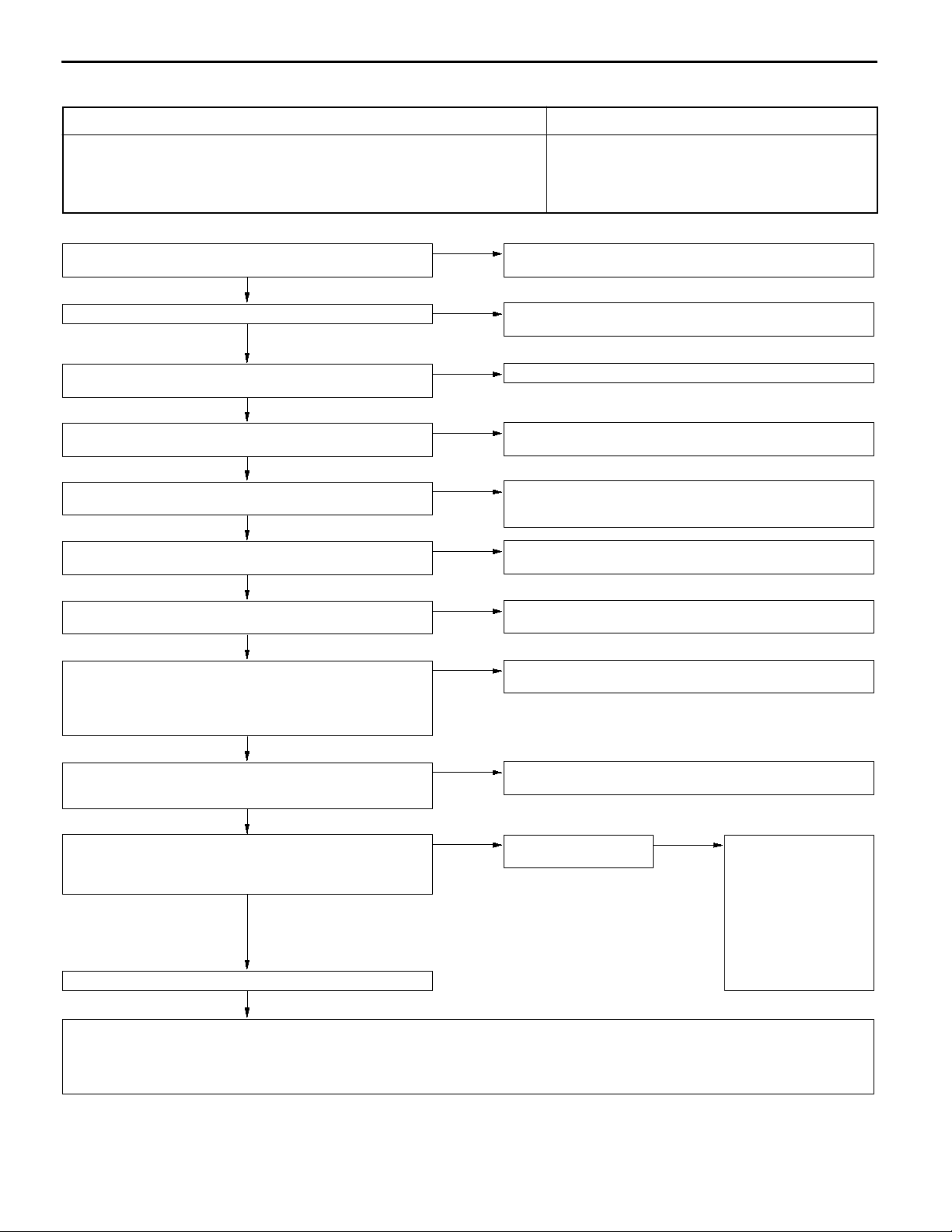
13A-52
INSPECTION PROCEDURE 15
MPI <4G1> -
Troubleshooting
Hesitation, sag or stumble
In cases such as the above, the cause is probably that ignition system, air/fuel mixture
or compression pressure is defective.
MUT-IISelf-Diag code
Are diagnosis codes displayed?
No
Check the injectors for operation sound.
OK
Check the ignition timing.
(Refer to GROUP 11B - On-vehicle Service.)
OK
MUT-IIData list
13 Intake air temperature sensor (Refer to P.13A-65.)
OK
MUT-IIData list
21 Engine coolant temperature sensor (Refer to P.13A-66.)
OK
MUT-IIData list
14 Throttle position sensor (Refer to P.13A-65.)
OK
MUT-IIActuator test
10 EGR control solenoid valve (Refer to P.13A-70.)
OK
MUT-IIData list
59 Oxygen sensor (rear)
D Transmission: 2nd gear
D Driving with throttle widely open
OK:
600 - 1,000 mV
OK
MUT-IIData list
11 Oxygen sensor (front)
OK:
600 - 1,000 mV during sudden racing
OK
MUT-IIData list
11 Oxygen sensor (front)
OK:
Changes between 0 - 400 mV and 600 - 1,000 mV during
idling
OK
Check the fuel pressure. (Refer to P.13A-78*.)
OK
Yes
NG
NG
NG
NG
NG
NG
NG
NG
NG
Refer to P.13A-9, INSPECTION CHART FOR DIAGNOSIS
CODES.
Check the injector system. (Refer to P.13A-26, INSPECTION PROCEDURE FOR DIAGNOSIS CODE P0201, P0202, P0203, P0204.)
Check that the distributor is installed properly.
Check theintake air temperature sensorsystem. (Referto P.13A-12,
INSPECTION PROCEDURE FOR DIAGNOSIS CODE P0110.)
Check the engine coolant temperature sensor system.
(Refer to P.13A-13, INSPECTION PROCEDURE FOR DIAGNOSIS
CODE P0115.)
Check the throttle position sensor system. (Refer to P.13A-16, INSPECTION PROCEDURE FOR DIAGNOSIS CODE P0120.)
Check the EGR control solenoid valve system. (Refer to P.13A-32,
INSPECTION PROCEDURE FOR DIAGNOSIS CODE P0403.)
Check the oxygen sensor (rear) system. (Refer to P.13A-22, INSPECTION PROCEDURE FOR DIAGNOSIS CODE P0136.)
Check the oxygen sensor (front) system. (Refer to P.13A-19, INSPECTION PROCEDURE FOR DIAGNOSIS CODE P0130.)
Check the fuel pressure.
(Refer to P.13A-78*.)
Probable cause
D Malfunction of the ignition system
D Malfunction of air-fuel ratio control system
D Malfunction of the fuel supply system
D Malfunction of the EGR control solenoid valve system
D Poor compression
OK
1. Inspect the intake of
air into the air intake
system.
D Broken intake man-
ifold gasket
D Broken vacuum hose
D PCV valve does not
operate.
D Broken airintake hose
2. Check the injector for
clog.
Check the following items.
D Check the ignition coil, spark plugs, spark plug cables. (Refer to GROUP 16 - On-vehicle Service.)
D Check the EGR control system. (Refer to GROUP 17 - Emission Control System.)
D Check the compression pressure. (Refer to GROUP 11B - On-vehicle Service.)
D Check the fuel filter or fuel line for clogging.
NOTE:
*: Refer to the ’96 COLT/LANCER Workshop Manual (Pub. No. PWME9511).
Page 83
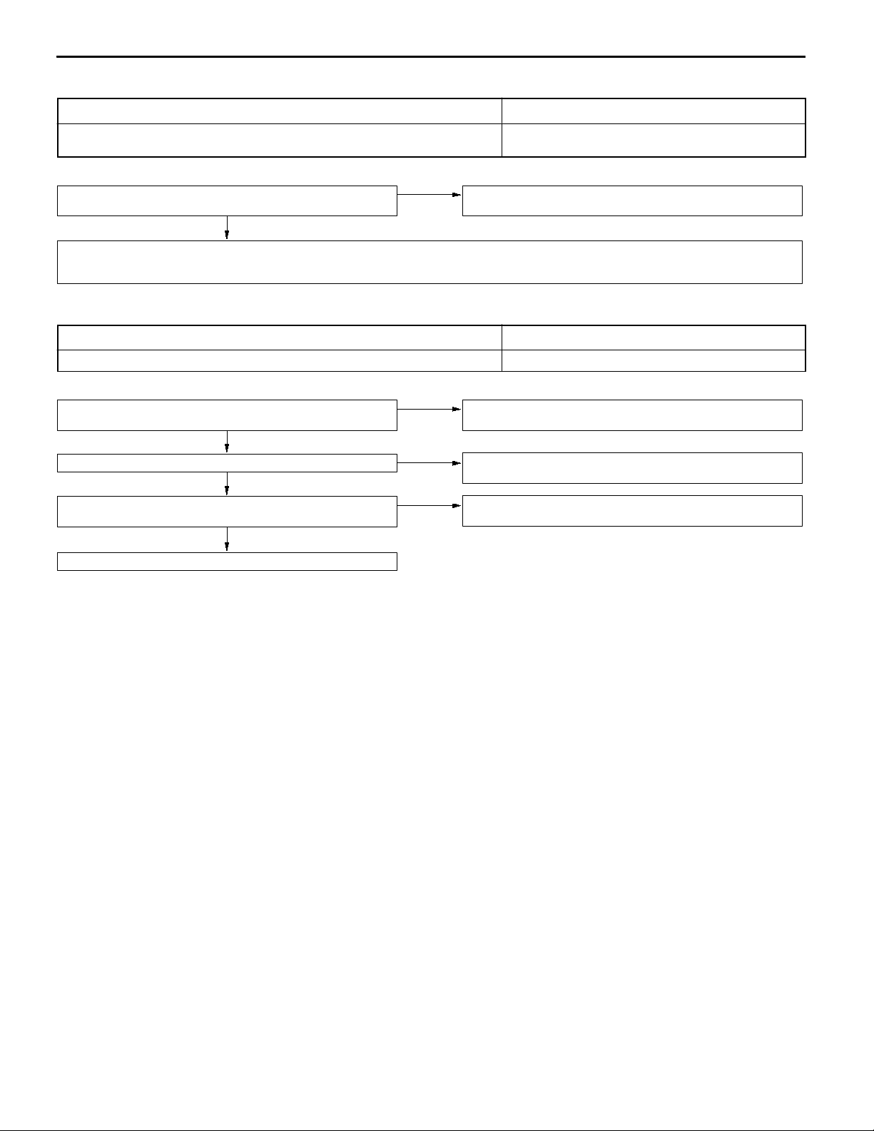
INSPECTION PROCEDURE 16
MPI <4G1> -
Troubleshooting
13A-53
The feeling of impact or vibration when accelerating
In cases such as the above, the cause is probably that there is an ignition leak
accompanying the increase in the spark plug demand voltage during acceleration.
Yes
MUT-IISelf-Diag code
Are diagnosis codes displayed?
No
Check the following items.
D Check the ignition coil, spark plugs, spark plug cables. (Refer to GROUP 16 - On-vehicle Service.)
D Check for occurrence of ignition leak.
Probable cause
D Malfunction of the ignition system
Refer to P.13A-9, INSPECTION CHART FOR DIAGNOSIS
CODES.
INSPECTION PROCEDURE 17
The feeling of impact or vibration when decelerating.
Malfunction of the ISC system is suspected. D Malfunction of the ISC system
MUT-IISelf-Diag code
Are diagnosis codes displayed?
No
Check the ISC servo for operation sound. (Refer to P.13A-88*.)
OK
MUT-IIData list
14 Throttle position sensor (Refer to P.13A-65.)
OK
Yes
NG
NG
Probable cause
Refer to P.13A-9, INSPECTION CHART FOR DIAGNOSIS
CODES.
Check the ISC system. (Refer to P.13A-36, INSPECTION PROCEDURE FOR DIAGNOSIS CODE P0505.)
Check the throttle position sensor system. (Refer to P.13A-16,
INSPECTION PROCEDURE FOR DIAGNOSIS CODE P0120.)
Clean the throttle valve area. (Refer to P.13A-75*.)
NOTE:
*: Refer to the ’96 COLT/LANCER Workshop Manual (Pub. No. PWME9511).
Page 84

13A-54
INSPECTION PROCEDURE 18
MPI <4G1> -
Troubleshooting
Poor acceleration
Defective ignition system, abnormal air-fuel ratio, poor compression pressure, etc.
are suspected.
MUT-IISelf-Diag code
Are diagnosis codes displayed?
No
Check the injectors for operation sound.
OK
Check the ignition timing.
(Refer to GROUP 11B - On-vehicle Service.)
OK
MUT-IIData list
13 Intake air temperature sensor (Refer to P.13A-65.)
OK
MUT-IIData list
21 Engine coolant temperature sensor (Refer to P.13A-66.)
OK
MUT-IIData list
14 Throttle position sensor (Refer to P.13A-65.)
OK
MUT-IIActuator test
10 EGR control solenoid valve (Refer to P.13A-70.)
OK
MUT-IIData list
59 Oxygen sensor (rear)
D Transmission: 2nd gear
D Driving with throttle widely open
OK:
600 - 1,000 mV
OK
MUT-IIData list
11 Oxygen sensor (front)
OK:
600 - 1,000 mV during sudden racing
OK
MUT-IIData list
11 Oxygen sensor (front)
OK:
Changes between 0 - 400 mV and 600 - 1,000 mV during
idling
OK
Check the fuel pressure. (Refer to P.13A-78*.)
OK
Yes
NG
NG
NG
NG
NG
NG
NG
NG
NG
Refer to P.13A-9, INSPECTION CHART FOR DIAGNOSIS
CODES.
Check the injector system. (Refer to P.13A-26, INSPECTION PROCEDURE FOR DIAGNOSIS CODE P0201, P0202, P0203, P0204.)
Check that the distributor is installed properly.
Check the intake air temperature sensor system.
(Refer to P.13A-12, INSPECTION PROCEDURE FOR DIAGNOSIS
CODE P0110.)
Check the engine coolant temperature sensor system.
(Refer to P.13A-13, INSPECTION PROCEDURE FOR DIAGNOSIS
CODE P0115.)
Check the throttle position sensor system. (Refer to P.13A-16, INSPECTION PROCEDURE FOR DIAGNOSIS CODE P0120.)
Check the EGR control solenoid valve system. (Refer to P.13A-32,
INSPECTION PROCEDURE FOR DIAGNOSIS CODE P0403.)
Check the oxygen sensor (rear) system. (Refer to P.13A-22, INSPECTION PROCEDURE FOR DIAGNOSIS CODE P0136.)
Check the oxygen sensor (front) system. (Refer to P.13A-19, INSPECTION PROCEDURE FOR DIAGNOSIS CODE P0130.)
Check the fuel pressure.
(Refer to P.13A-78*.)
Probable cause
D Malfunction of the ignition system
D Malfunction of air-fuel ratio control system
D Malfunction of the fuel supply system
D Poor compression pressure
D Clogged exhaust system
OK
1. Inspect the intake of
air into the air intake
system.
D Broken intake man-
ifold gasket
D Broken vacuum hose
D PCV valve does not
operate.
D Broken airintake hose
2. Check the injector for
clog.
Check the following items.
D Check the ignition coil, spark plugs, spark plug cables. (Refer to GROUP 16 - On-vehicle Service.)
D Check the compression pressure. (Refer to GROUP 11B - On-vehicle Service.)
D Check the fuel filter or fuel line for clogging.
D Broken air intake hose
D Clogged air cleaner
NOTE:
*: Refer to the ’96 COLT/LANCER Workshop Manual (Pub. No. PWME9511).
Page 85

INSPECTION PROCEDURE 19
MPI <4G1> -
Troubleshooting
13A-55
Surge
Defective ignition system, abnormal air-fuel ratio, etc. are suspected. D Malfunction of the ignition system
MUT-IISelf-Diag code
Are diagnosis codes displayed?
No
Check the injectors for operation sound.
OK
Check the ignition timing.
(Refer to GROUP 11B - On-vehicle Service.)
OK
MUT-IIData list
13 Intake air temperature sensor (Refer to P.13A-65.)
OK
MUT-IIData list
21 Engine coolant temperature sensor (Refer to P.13A-66.)
OK
MUT-IIData list
14 Throttle position sensor (Refer to P.13A-65.)
OK
MUT-IIActuator test
10 EGR control solenoid valve (Refer to P.13A-70.)
OK
MUT-IIData list
59 Oxygen sensor (rear)
D Transmission: 2nd gear
D Driving with throttle widely open
OK:
600 - 1,000 mV
OK
MUT-IIData list
11 Oxygen sensor (front)
OK:
600 - 1,000 mV during sudden racing
OK
MUT-IIData list
11 Oxygen sensor (front)
OK:
Changes between 0 - 400 mV and 600 - 1,000 mV during
idling
OK
Check the fuel pressure. (Refer to P.13A-78*.)
OK
Yes
NG
NG
NG
NG
NG
NG
NG
NG
NG
Probable cause
D Malfunction of air-fuel ratio control system
D Malfunction of the EGR control solenoid valve system
Refer to P.13A-9, INSPECTION CHART FOR DIAGNOSIS
CODES.
Check the injector system. (Refer to P.13A-26, INSPECTION PROCEDURE FOR DIAGNOSIS CODE P0201, P0202, P0203, P0204.)
Check that the distributor is installed properly.
Check the intake air temperature sensor system.
(Refer to P.13A-12, INSPECTION PROCEDURE FOR DIAGNOSIS
CODE P0110.)
Check the engine coolant temperature sensor system.
(Refer to P.13A-13, INSPECTION PROCEDURE FOR DIAGNOSIS
CODE P0115.)
Check the throttle position sensor system. (Refer to P.13A-16, INSPECTION PROCEDURE FOR DIAGNOSIS CODE P0120.)
Check the EGR control solenoid valve system. (Refer to P.13A-32,
INSPECTION PROCEDURE FOR DIAGNOSIS CODE P0403.)
Check the oxygen sensor (rear) system. (Refer to P.13A-22, INSPECTION PROCEDURE FOR DIAGNOSIS CODE P0136.)
Check the oxygen sensor (front) system. (Refer to P.13A-19, INSPECTION PROCEDURE FOR DIAGNOSIS CODE P0130.)
Check the fuel pressure.
(Refer to P.13A-78*.)
OK
1. Inspect the intake of
D Broken intake man-
D Broken vacuum hose
D PCV valve does not
D Broken airintake hose
2. Check the injector for
air into the air intake
system.
ifold gasket
operate.
clog.
Check the following items.
D Check the ignition coil, spark plugs, spark plug cables. (Refer to GROUP 16 - On-vehicle Service.)
D Check the EGR control system. (Refer to GROUP 17 - Emission Control System.)
NOTE:
*: Refer to the ’96 COLT/LANCER Workshop Manual (Pub. No. PWME9511).
Page 86

13A-56
INSPECTION PROCEDURE 20
MPI <4G1> -
Troubleshooting
Knocking
In cases as the above, the cause is probably that the detonation control is defective
or the heat value of the spark plug is inappropriate.
MUT-IISelf-Diag code
Are diagnosis codes displayed?
No
Does knocking occur when driving with the detonation sensor
connector disconnected? At this time, use the MUT-II to check
if the timing is retarded compared to when the detonation sensor
connector is disconnected.
Yes
Check the following items.
D Spark plugs
D Check if foreign materials (water, alcohol, etc.) got into fuel.
Yes
No
Probable cause
D Defective detonation sensor
D Inappropriate heat value of the spark plug
Refer to P.13A-9, INSPECTION CHART FOR DIAGNOSIS
CODES.
Check the detonation sensor system. (Refer to P.13A-29, INSPECTION PROCEDURE FOR DIAGNOSIS CODE P0325.)
INSPECTION PROCEDURE 21
Dieseling
Fuel leakage from injectors is suspected. D Fuel leakage from injectors
Check the injectors for fuel leakage.
Probable cause
Page 87

INSPECTION PROCEDURE 22
MPI <4G1> -
Troubleshooting
13A-57
Too high CO and HC concentration when idling
Abnormal air-fuel ratio is suspected. D Malfunction of the air-fuel ratio control system
MUT-IISelf-Diag code
Are diagnosis codes displayed?
No
Check the ignition timing.
(Refer to GROUP 11B - On-vehicle Service.)
OK
MUT-IIData list
21 Engine coolant temperature sensor. (Refer to P.13A-66.)
OK
MUT-IIData list
13 Intake air temperature sensor (Refer to P.13A-65.)
OK
MUT-IIData list
59 Oxygen sensor (rear)
D Transmission: 2nd gear
D Driving with throttle widely open
OK:
600 - 1,000 mV
OK
MUT-IIData list
11 Oxygen sensor (front)
OK:
600 - 1,000 mV when racing suddenly
OK
MUT-IIData list
11 Oxygen sensor (front)
OK:
Repeat 0 - 400 mV and 600 - 1,000 mV alternately when
idling.
NG
Check the fuel pressure. (Refer to P.13A-78*.)
OK
Yes
NG
NG
NG
NG
NG
OK
Probable cause
D Deteriorated catalyst
Refer to P.13A-9, INSPECTION CHART FOR DIAGNOSIS
CODES.
Check that the distributor is installed properly.
Check the engine coolant temperature sensor system.
(Refer to P.13A-13, INSPECTION PROCEDURE FOR DIAGNOSIS
CODE P0115.)
Check the intake air temperature sensor system.
(Refer to P.13A-12, INSPECTION PROCEDURE FOR DIAGNOSIS
CODE P0110.)
Check the oxygen sensor (rear) system. (Refer to P.13A-22,
INSPECTION PROCEDURE FOR DIAGNOSIS CODE P0136.)
Check the oxygen sensor (front) system. (Refer to P.13A-19,
INSPECTION PROCEDURE FOR DIAGNOSIS CODE P0130.)
Replace the oxygen sensor.
Check the trouble symptom.
NG
Check the following items.
D Check the injectors for operation sound.
D Check the injectors for fuel leakage.
D Check the ignition coil, spark plugs, spark plug cables. (Refer to GROUP 16 - On-vehicle Service.)
D Check the compression pressure. (Refer to GROUP 11B - On-vehicle Service.)
D Check the positive crankcase ventilation system. (Refer to GROUP 17 - Emission Control System.)
D Check the purge control system. (Refer to GROUP 17 - Emission Control System.)
D Check the EGR control system. (Refer to GROUP 17 - Emission Control System.)
Check the trouble symptom.
NG
Replace the catalytic converter.
NOTE:
*: Refer to the ’96 COLT/LANCER Workshop Manual (Pub. No. PWME9511).
Page 88

13A-58
INSPECTION PROCEDURE 23
MPI <4G1> -
Troubleshooting
Fans (radiator fan, A/C condenser fan) are inoperative.
The fan motor relay is controlled by the power transistor inside the engine-ECU turning
ON and OFF.
Measure at the engine-ECU connector B-37.
D Disconnect the connector, and measure at the harness side.
D Check the condition of the fans (radiator fan and A/C condenser
fan). (Ignition switch: ON)
OK:
D Voltage between 20 and earth, 21 and earth
D Connect a jumper wire between 20 and earth
D Connect a jumper wire between 21 and earth
Check the following connector:
Check the trouble symptoms.
MUT-IIData list
21 Engine coolant temperature sensor
OK:
Check the thermostat.
Fans are stopped
(Ignition switch: ON)
OK:
System voltage
(Ignition switch: ON)
OK:
Radiator fan and condenser fan run at high speed.
(Ignition switch: ON)
OK:
Radiator fan and condenser fan run at low speed.
OK
B-37
OK
NG
After the engine has warmed up, the engine coolant temperature durning idling is identical to the MUT-II reading.
OK
OK
NG
NG
NG
NG
D Check the radiator fan circuit. (Referto ELECTRICAL WIRING.)
D Check the A/C condenser fan circuit.
Repair
Check the engine coolant temperature sensor system.
(Refer to P.13A-13, INSPECTION PROCEDURE FOR DIAGNOSIS
CODE P0115.)
Replace
Probable cause
D Malfunction of the fan motor relay
D Malfunction of the fan motor
D Malfunction of the thermostat
D Improper connector contact, open circuit or
short-circuited harness wire
D Malfunction of the engine-ECU
(Refer to ELECTRICAL WIRING.)
Replace the engine-ECU.
Page 89

MPI <4G1> -
Troubleshooting
INSPECTION PROCEDURE 24
Check the engine-ECU power supply and earth circuit.
13A-59
Measure the engine-ECU connectors, B-34, B-36, B-37.
D Disconnect the connector and measure at the harness side
1. Voltage between 82 and earth (Ignition switch: ON)
OK:
2. Voltage between 38 and earth
3. Voltage between 12, 25 and earth (Ignition switch: ON)
4. Continuity between 13, 26 and earth
5. Voltage between 80 and earth
Check the following
connectors:
B-34, B-36, B-37
Check the trouble symptom.
Replace the engine-ECU.
Check the following connectors:
B-32, B-34, B-48, B-62, B-69
Check the trouble symptom.
Check the harness wire between engine-ECU and battery, and
repair if necessary.
System voltage
OK:
System voltage
OK:
System voltage (when the terminal 38 is earthed)
OK:
Continuity
OK:
System voltage
OK
NG
OK
NG
OK
NG
Repair
NG
Repair
1. NG
2., 3. NG
4. NG
5. NG
Check the following
connectors:
Check the trouble symptom.
Check the harness wire
between engine-ECU and
ignition switch connector.
Check the ignition switch.
(Refer to GROUP 54 - Ignition Switch and Immobilizer System.)
Check the following
connectors:
Check the trouble symptoms.
Check the harness wire between engine-ECU and control relay
connector, and repair if necessary.
Check the harness wire between engine-ECU and earth, and repair
if necessary.
B-32, B-70
OK
OK
OK
B-36, B-37
OK
NG
NG
NG
NG
Repair
Repair
Repair
INSPECTION PROCEDURE 25
Power supply system and ignition switch-IG system
When an ignition switch ON signal is input to the engine-ECU, the engine-ECU turns
the control relay ON. This causes battery voltage to be supplied to the engine-ECU,
injectors and air flow sensor.
Check the control relay. (Refer to P.13A-83*.)
OK
Measure at the control relay connector B-13.
D Disconnect the connector, and measure at the harness side.
D Voltage between 3, 4 and earth
OK:
System voltage
OK
Check the engine-ECU power supply and earth circuit.
(Refer to P.13A-59, INSPECTION PROCEDURE 24.)
NG
NG
Replace
Probable cause
D Malfunction of the ignition switch
D Malfunction of the control relay
D Improper connector contact, open circuit or
short-circuited harness wire
D Disconnected engine-ECU earth wire
D Malfunction of the engine-ECU
Check the following
connector:
Check the trouble symptom.
Check the harnesswire between batteryand control relay connector,
and repair if necessary.
A-10
OK
NG
NG
NOTE:
*: Refer to the ’96 COLT/LANCER Workshop Manual (Pub. No. PWME9511).
Repair
Page 90

13A-60
INSPECTION PROCEDURE 26
MPI <4G1> -
Troubleshooting
Fuel pump system
The engine-ECU turns the fuel pump relay ON when the engine is cranking or running,
and this supplies power to drive the fuel pump.
Check the fuel pump operation.
(Refer to P.13A-81*.)
OK
Check the fuel pump relay.
(Refer to P.13A-83*.)
OK
NG
NG
Measure at the fuel pump connector
D-14.
D Disconnect the connector, and
measure at the harness side.
D Continuity between 2 and earth
OK:
Continuity
OK
Check the following connectors:
B-12, B-33, D-04, D-14
OK
Replace
Check the trouble symptom.
NG
Check the harness wire between the
fuel pump relay and fuel pump connector.
OK
Replace the fuel pump.
Probable cause
D Malfunction of the fuel pump relay
D Malfunction of the fuel pump
D Improper connector contact, open circuit or
short-circuited harness wire
D Malfunction of the engine-ECU
NG
NG
NG
Check the following connectors:
D-04, D-14
OK
Check the trouble symptom.
Repair
Check the harness wire between the
fuel pump andearth, and repair if necessary.
Repair
NG
NG
Repair
Measure at the fuel pump relay connector B-12.
D Connect the connector.
D Voltage between 1 and earth
MUT-IIActuator test:
D
drive
OK:
System voltage
Check the harness wire between fuel
pump relay connector and fuel pump,
and repair if necessary.
Fuel pump
OK
NG
Measure at the fuel pump relay connector B-12.
D Disconnect the connector, and
measure at the harness side.
D Voltage between 4 and earth
(Ignition switch: ON)
OK:
System voltage
OK
Measure at the engine-ECU connector
B-37.
D Disconnect the connector, and
measure at the harness side.
D Voltage between 22 <Vehicles with
immobilizer system>, 8 <Vehicles
without immobilizer system> and
earth (Ignition switch: ON)
OK:
System voltage
OK
Check the following connector:
OK
Check the trouble symptom.
NG
Replace the engine-ECU.
B-37
NG
NG
NG
Check the following connectors:
B-32, B-70
OK
Check the trouble symptom.
NG
Check the harness wire between the
fuel pump relay and ignition switch connector.
OK
Check the ignition switch.
(Refer to GROUP 54 - Ignition Switch
and Immobilizer System.)
Check the following connector:
OK
Repair
Check the trouble symptom.
NG
Check the harness wire between the
engine-ECU and the fuel pump relay,
and repair if necessary.
NG
Repair
NG
Repair
B-12
NG
Repair
NOTE:
*: Refer to the ’96 COLT/LANCER Workshop Manual (Pub. No. PWME9511).
Page 91

INSPECTION PROCEDURE 27
MPI <4G1> -
Troubleshooting
13A-61
Ignition switch-ST system
The ignition switch-ST inputs a HIGH signal to the engine-ECU while the engine is
cranking.
The engine-ECU controls fuel injection, etc. during starting based on this input.
Measure at the engine-ECU connector B-34.
D Disconnect the connector, and measure at the harness side.
D Voltage between 71 and earth (Ignition switch: START)
OK:
8V or more
OK
Check the following
connector:
Check the trouble symptom.
Replace the engine-ECU.
B-34
OK
NG
NG
Repair
NG
INSPECTION PROCEDURE 28
Power steering fluid pressure switch system
The presence or absence of power steering load is input to the engine-ECU.
The engine-ECU controls the idle speed control (ISC) servo based on this input.
Probable cause
D Malfunction of ignition switch
D Improper connector contact, open circuit or
short-circuited harness wire
D Malfunction of the engine-ECU
Check the following connectors:
Check the trouble symptom.
Check harness wire between
the engine-ECU and ignition
switch connector.
Check the ignition switch.
(Refer to GROUP 54 - Ignition Switch and Immobilizer system.)
B-33, B-34
OK
NG
OK
NG
NG
Repair
Repair
Probable cause
D Malfunction of power steering fluid pressure switch
D Improper connector contact, open circuit or
short-circuited harness wire
D Malfunction of the engine-ECU
Check the power steering fluid pressure switch.
(Refer to GROUP 37A - On-vehicle Service.)
OK
Measure at the power steering fluid pressure switch connector
A-78.
D Disconnect the connector, and measure at the harness side.
D Voltage between 1 and earth (Ignition switch: ON)
OK:
System voltage
OK
Check the following
connector:
Check the trouble symptom.
Replace the engine-ECU.
A-78
OK
NG
NG
Repair
NG
NG
Replace
Check the following
connectors:
Check the trouble symptom.
Check harness wire
between engine-ECU and
power steering fluid pressure switch connector.
Replace the engine-ECU.
A-10, B-36
OK
NG
OK
NG
NG
Repair
Repair
Page 92
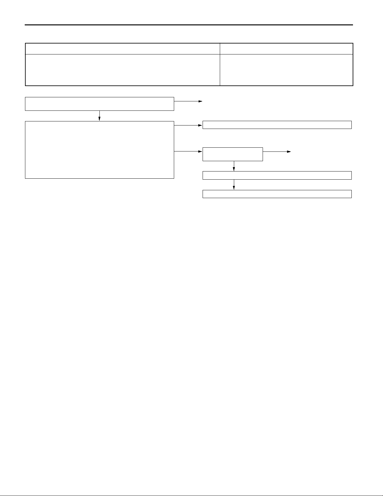
13A-62
INSPECTION PROCEDURE 29
MPI <4G1> -
Troubleshooting
A/C switch and A/C relay system
When an A/C ON signal is input to the engine-ECU, the engine-ECU carries out
control of the idle speed control (ISC) servo, and also operates the A/C compressor
magnetic clutch.
Check the A/C compressor relay.
(Refer to GROUP 55 - On-vehicle Service.)
OK
Measure at the engine-ECU connectors B-36, B-37.
D Disconnect the connectors, and measure at the harness side.
D Voltage between 8 <Vehicles with immobilizer system>, 22
<Vehicles without immobilizer system> and earth, and 45 and
earth (Ignition switch: ON, A/C switch: ON)
OK:
D Short circuit between 8 <Vehicles with immobilizer system>,
System voltage
22 <Vehicles without immobilizer system> and earth(Ignition
switch: ON, A/C switch: ON)
OK:
A/C compressor clutch turns on.
NG
NG
OK
Replace
Check the A/C system. (Refer to GROUP 55 - On-vehicle Service.)
Check the following
connectors:
Check the trouble symptom.
Replace the engine-ECU.
Probable cause
D Malfunction of A/C control system
D Malfunction of A/C switch
D Improper connector contact, open circuit or
short-circuited harness wire
D Malfunction of the engine-ECU
NG
B-36, B-37
OK
NG
Replace
Page 93

INSPECTION PROCEDURE 30
MPI <4G1> -
Troubleshooting
13A-63
Ignition circuit system
The engine-ECU interruptsthe ignition coilprimary currentby turningthe power transistor
inside the engine-ECU ON and OFF .
Check the ignition coil.
(Refer to GROUP 16 - Ignition System.)
OK
Check the ignition failure sensor.
(Refer to GROUP 16 - Ignition System.)
OK
Measure at the ignition failure sensor connector A-107.
D Disconnect the connector and measure at the harness side.
Voltage between 4 and ground (Ignition switch: ON)
OK:
System voltage
OK
NG
NG
Replace
Replace
NG
Check the following
connectors:
Check the trouble symptom.
Check the harness wire
between the ignition
failure sensor and ignition
switch connector.
Check the ignition switch. (Refer to GROUP 54 - Ignition Switch.)
Probable cause
D Malfunction of ignition coil
D Malfunction of ignition failure sensor
D Improper connector contact, open circuit or
short-circuited harness wire
D Malfunction of the engine-ECU
NG
B-32, B-70
OK
NG
NG
OK
Repair
Repair
Measure at the ignition coil connectors
A-73, A-79.
D Disconnect the connector, and
measure at the harness side.
1. Voltage between 1 and earth
(Ignition switch: ON)
OK:
2. Voltage between 3 and earth
3. Continuity between 2 and earth
Check the following connectors:
A-73, A-79
Check the trouble symptom.
To the next page
Battery positive voltage
(Engine: Cranking)
OK:
0.5 - 4.0 V
OK:
Continuity
OK
OK
NG
Repair
NG
1. NG
2. NG
3. NG
Check the following connector:
A-107
OK
Check the trouble symptom. Check the harness wire between the
Check the following connector:
B-37
OK
Check the trouble symptom.
NG
Check the harness wire between the
engine-ECU and ignition coil connector.
OK
Replace the engine-ECU.
Check the harness wire between the
ignition coil connector and ground, and
repair if necessary.
NG
NG
NG
NG
Repair
ignition coil and ignition failure sensor
connector, and repair if necessary.
Repair
Repair
Page 94
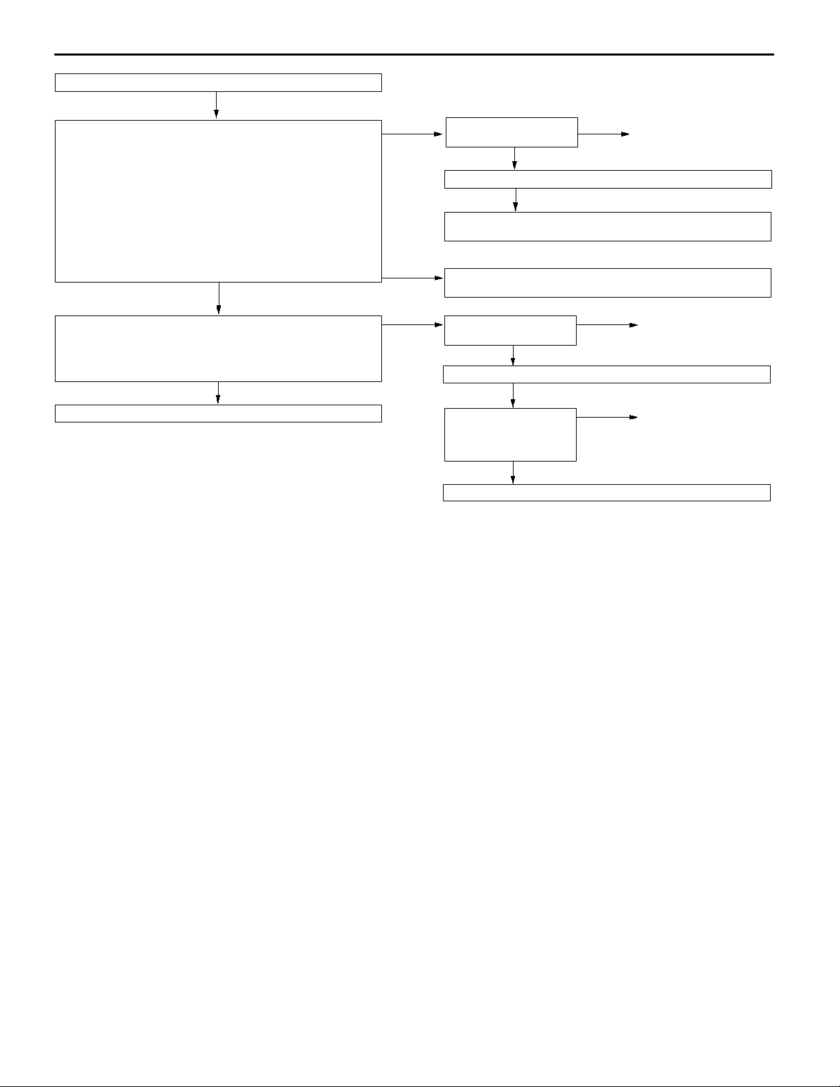
13A-64
From the previous page
OK
Measure at the ignition failure sensor connector A-107.
D Disconnect the connector and measure at the harness side.
1. Voltage between 2 and earth (Ignition switch: ON)
OK:
OK:
4 V or more
Continuity
2. Continuity between 1 and earth
MPI <4G1> -
Troubleshooting
1. NG
Check the following
connector:
Check the trouble symptom.
There is an open or short-circuit the ignition signal output harness
of the ignition failure sensor, so check and repair the harness.
B-35
OK
NG
NG
Repair
OK
Measure at the engine-ECU connector B-35.
D Measure with the connector connected.
D Voltage between 58 and earth
(Engine: Cranking or 3,000 r/min)
OK:
0.3 - 3.0 V
OK
Replace the engine-ECU.
2. NG
NG
Check the harness wire between the ignition failure sensor and
earth, and repair if necessary.
Check the following
connector:
Check the trouble symptom.
Check the harness wire
between the engine-ECU
and the ignition failure
sensor connector.
Replace the ignition failure sensor .
A-107
OK
NG
OK
NG
NG
Repair
Repair
Page 95

MPI <4G1> -
Troubleshooting
13A-65
DATA LIST REFERENCE TABLE
NOTE
*1: In a new vehicle [driven approximately 500 km or less], the air intake plenum pressure is sometimes
10 % higher than the standard pressure.
*2: The injector drive time represents the time when the cranking speed is at 250 r/min or below when
the power supply voltage is 11 V.
*3: In a new vehicle [driven approximately 500 km or less], the injector drive time is sometimes 10 %
longer than the standard time.
*4: In a new vehicle [driven approximately 500 km or less], the step of the stepper motor is sometimes
30 steps greater than the standard value.
Item
No.
11 Oxygen
13 Intake air
Inspection
item
sensor
(front)
temperature
sensor
Inspection contents Normal condition Inspection
procedure
No.
Engine: After having
warmed up
Air/fuel mixture is
made leaner when
made leaner when
decelerating, and is
made richer when
racing.
Engine: After having
warmed up
The oxygen sensor
signal is used to
check the air/fuel
mixture ratio, and
control condition is
also checked by the
ECU.
Ignition switch: ON or
with engine running
When at 4,000 r/min,
engine is suddenly
decelerated
When engine is
suddenly raced
Engine is idling 400 mV or less
2,500 r/min
When intake air
temperature is
-20_C
When intake air
temperature is 0_C
200 mV or less Code No.
600 - 1,000 mV
(Changes)
600 - 1,000 mV
-20_C Code No.
0_C
P0130
P0110
Reference
page
13A-19
13A-12
When intake air
temperature is 20_C
When intake air
temperature is 40_C
When intake air
temperature is 80_C
14 Throttle Ignition switch: ON Set to idle position 300 - 1,000 mV Code No. 13A-16
position
sensor
Gradually open Increases in
Open fully 4,500 - 5,500 mV
20_C
40_C
80_C
P0120
proportion to
throttle opening
angle
Page 96

13A-66
MPI <4G1> -
Troubleshooting
Item
No.
16 Power
18 Cranking
21 Engine
Inspection
item
supply
voltage
signal
signal
(ignition
switch-ST)
coolant
temperature
sensor
Inspection contents Normal condition Inspection
procedure
No.
Ignition switch: ON System voltage Procedure
No. 25
Ignition switch: ON Engine: Stopped OFF Procedure
No. 27
No. 27
Engine: Cranking ON
Ignition switch: ON or
with engine running
When engine
coolant temperature
is - 20_C
When engine
coolant temperature
is 0_C
When engine
coolant temperature
is 20_C
When engine
coolant temperature
is 40_C
-20_C Code No.
P0115
0_C
20_C
40_C
Reference
page
13A-59
13A-61
13A-13
22 Crank angle
sensor
D Engine: Cranking
D Tachometer:
Connected
D Engine: Idling
D Idle position
switch: ON
When engine
coolant temperature
is 80_C
Compare the engine
speed readings on
the tachometer and
the MUT-II.
When engine
coolant temperature
is - 20_C
When engine
coolant temperature
is 0_C
When engine
coolant temperature
is 20_C
When engine
coolant temperature
is 40_C
When engine
coolant temperature
is 80_C
80_C
Accord Code No.
P0335
1,475 - 1,675
r/min
1,345 - 1,545
r/min
1,200 - 1,400
r/min
1,025 - 1,225
r/min
650 - 850 r/min
13A-29
24 Vehicle
speed sensor
Drive at 40 km/h Approximately 40
km/h
Code No.
P0500
13A-35
Page 97

MPI <4G1> -
Troubleshooting
13A-67
Item
No.
27 Power
28 A/C switch Engine: Idling
32 V acuum
Inspection
item
steering fluid
pressure
switch
sensor*
1
Inspection contents Normal condition Inspection
Engine: Idling Steering wheel
(when A/C switch is
(when A/C switch is
ON, A/C compressor
should be operating.)
D Engine coolant
temperature: 80 95_C
D Lamps, electric
cooling fan and all
accessories: OFF
D Transmission:
Neutral
D Ignition switch: ON
procedure
No.
OFF Procedure
stationary
Steering wheel
turning
A/C switch: OFF OFF Procedure
A/C switch: ON ON
Engine: Stopped
(At altitude of 0 m)
Engine: Stopped (At
altitude of 600 m)
Engine: Stopped (At
altitude of 1,200 m)
Engine: Stopped (At
altitude of 1,800 m)
Engine: Idling 24.3 - 37.7 kPa
ON
101 kPa Code No.
95 kPa
88 kPa
81 kPa
No. 28
No. 29
No. 29
P0105
Reference
page
13A-61
13A-62
13A-10
41 Injectors*
When engine is
suddenly raced
2
Engine: Cranking When engine
coolant temperature
is 0_C (injection is
carried out for all
cylinders
simultaneously)
When engine
coolant temperature
is 20_C
When engine
coolant temperature
is 80_C
Increases
13 - 23 ms - -
26 - 46 ms
8 - 12 ms
Page 98

13A-68
MPI <4G1> -
Troubleshooting
Item
No.
41 Injectors*
44 Ignition
45 ISC
item
coils and
power
transistors (The timing lamp is
(stepper)
motor
position*
3
D Engine coolant
temperature:
80 – 95_C
D Lamps, electric
cooling fan and all
cooling fan and all
accessories: OFF
D Transmission:
Neutral
D Engine: After
having warmed up
D Timing lamp is set.
set in order to
check actual
ignition timing.)
D Engine coolant
temperature:
4
80 - 95_C
D Lamps, electric
cooling fan and all
accessories: OFF
accessories: OFF
D Transmission:
Neutral
D Engine: Idling
D When A/C switch is
ON, A/C
compressor should
be operating
Normal conditionInspection contentsInspection
Engine is idling 1.7 - 2.9 ms - -
2,500 r/min 1.4 - 2.6 ms
When engine is
suddenly raced
Engine is idling 0-20_BTDC - -
2,500 r/min 19 - 39 _BTDC
A/C switch: OFF 2 - 25 STEP - -
A/C switch:
OFF ® ON
Increases
Increases by
10 - 70 steps
Inspection
procedure
No.
Reference
page
49 A/C relay Engine: After having
warmed up/Engine is
idling
59 Oxygen
sensor
(rear)
D Transmission:
2nd gear
D Drive with throttle
widely open
A/C switch: OFF OFF (Compressor
clutch is not
operating)
A/C switch: ON ON (Compressor
clutch is
operating)
3,500 r/min 600 - 1,000 mV Code No.
Procedure
No. 29
P0136
13A-62
13A-22
Page 99

MPI <4G1> -
Troubleshooting
13A-69
Item
No.
81 Long-term
82 Short-term
87 Calculation Engine: Warm Engine: Idling 20 - 33 % - -
88 Fuel control Engine: Warm 2,500 r/min Closed loop Code No. 13A-18
A1 Oxygen
item
fuel compensation
fuel compensation
load value
condition
sensor
(front)
Engine: Warm, 2,500 r/min without any load
(during closed loop)
Engine: Warm, 2,500 r/min without any load
(during closed loop)
2,500 r/min 20 - 33 %
When engine is
suddenly raced
Engine: After having
warmed up
Air/fuel mixture is
made leaner when
decelerating, and is
made richer when
racing.
When at 4,000
r/min, engine is
suddenly decelerated
When engine is
sudden racing
Normal conditionInspection contentsInspection
-12.5 - 12.5 % Code No.
-17 - 17 % Code No.
Open loop - drive
condition
0.2 V or less Code No.
0.6 - 1.0 V
Inspection
procedure
No.
P0170
P0170
P0125
P0130
Reference
page
13A-25
13A-25
13A-19
Engine: After having
warmed up
The oxygen sensor
signal is used to
check the air/fuel
mixture ratio, and
control condition is
also checked by the
engine-ECU.
A2 Oxygen
sensor
(rear)
8A Throttle D Ignition switch: ON Set to idle position 6 - 20 % Code No. 13A-16
position
sensor
(Throttle
opening
angle)
D Transmission:
2nd gear
D Drive with throttle
widely open
Engine is idling 0.4 V or less
(Changes)
0.6 - 1.0 V
2,500 r/min
3,500 r/min 0.6 - 1.0 V Code No.
P0136
P0120
Gradually open Increase in
proportion to
throttle opening
angle
Open fully 80 - 100 %
13A-22
Page 100

13A-70
MPI <4G1> -
ACTUATOR TEST REFERENCE TABLE
Troubleshooting
Item
No.
01 Injectors Cut fuel to No. 1
02 Cut fuel to No. 2
03 Cut fuel to No. 3
04 Cut fuel to No. 4
07 Fuel pump Fuel pump
Inspection
item
Drive contents Inspection contents Normal condition Inspection
injector
injector
injector
injector
operates and
fuel is recirculated.
Engine:
After having warmed up/Engine is idling
(Cut the fuel supply to each
injector in turn and check
cylinders which don’t affect
idling.)
D Engine:
Cranking
D Fuel
pump:
Forced
driving
Inspect
according
to both the
above
conditions.
Pinch the
return hose
with fingers
to feel the
pulse of the
fuel being
recirculated.
Listen near
the fuel tank
for the
sound of fuel
pump
operation.
procedure
No.
Idling condition
becomes different
(becomes unstable).
Pulse is felt. Procedure
Sound of operation
is heard.
Code No.
P0201
Code No.
P0202
Code No.
P0203
Code No.
P0204
No. 26
Reference
page
13A-26
13A-60
08 Purge
control
solenoid
valve
10 EGR
control
solenoid
valve
20 Condenser
fan
21 Radiator
fan
Solenoid valve
turns from OFF
to ON.
Solenoid valve
turns from OFF
to ON.
Drive the fan
motors
(condenser)
Drive the fan
motors
(radiator)
Ignition switch: ON Sound of operation
can be heard when
solenoid valve is
driven.
Ignition switch: ON Sound of operation
can be heard when
solenoid valve is
driven.
D Ignition switch: ON
D A/C switch: ON
D Ignition switch: ON Fan motor runs Procedure
Fan motor runs Procedure
Code No.
P0443
Code No.
P0403
No. 23
No. 23
13A-34
13A-32
13A-58
13A-58
 Loading...