


FOREWORD
This service manual is written to familiarize you with the maintenance of your L-series Diesel Engine. If the engine is
carefully maintained, it will deliver a long productive life and efficient performance marked by power and economy.
Before attempting to inspect, disassemble, or repair the engine, read this manual carefully to learn more about the
engine and how to care for it properly. All descriptions, illustrations, specifications and serial numbers in this manual
are effective as of the date of printing of this manual.
The information contained in this manual applies to the engine model produced at the time of publication. It should
be noted that specifications and design may change due to improvements made thereafter.
What this manual covers
This service manual covers standard specifications for the L-series Mitsubishi Diesel Engine, and describes
• Specification
• Maintenance standard
• Adjustment
• Disassembly, inspection and repair
• Reassembly
In addition to the Summary of Manual Contents, a short summary of contents is found on the first page of each
group of the manual.
Operation and periodic maintenance are described in the Operation & Maintenance Manual, component parts and
ordering of service parts are described in the Parts Catalogue. Structure and function of the engine are described in
the various training manuals.
How to use this manual
1. Parts in illustrations are numbered to correspond with references to those numbers in the disassembly
sequence.
2. Items or conditions to be inspected during disassembly are enclosed in a box in the disassembled views:
3. Clogged oil hole
4. Maintenance standards for inspection and repair are described in text where they are relevant. For a quick
summary of maintenance standards, refer to group 9 of this manual.
5. Tightening torque under wet conditions is indicated as “(wet)” in text, drawings and tables. When so indicated as
(wet), apply engine oil to the threaded portion of the fastener. Unless indicated as such, the tightening torque is
to be assumed in the dry condition.
6. Measurements are based on the International System of Units (SI), and they are converted to the metric and
English system units in this manual based on the following conversion rates.
• Pressure 1 Mpa = 10.197 kgf/cm
• Torque N·m = 0.10197 kgf·m
• Force N = 0.10197 kgf
• Horsepower 1 kW = 1.341 HP = 1.3596 PS
2
Service Manual
Mitsubishi L-Series diesel engines
Version 08/2004
Copyright © 2004 MHI Equipment Europe B.V.
Service Manual Mitsubishi L-Series diesel engines
Version 08/2004
ENGLISH
1 / 155

WARNING SIGNS
The following safety related signs are used in this manual to emphasize important and critical instructions:
Indicates the most serious specific potential hazard which could result in
serious personal injury or death.
DANGER
Indicates a specific potential hazard which could result in personal injury.
WARNING
Indicates operating procedures, practices, etc. which could result in personal
CAUTION
injury or damage causing destruction to the engine. Some of the CAUTION
signs also indicate a specific potential hazard which could result in serious
personal injury or death.
Indicates procedures, conditions, etc. which are important to highlight.
NOTE
2 / 155
ENGLISH
Service Manual Mitsubishi L-Series diesel engines
Version 08/2004

TERMS USED IN THIS MANUAL
Before reading this manual, note that the following special terms are used in dimensional and other specifications.
Assembly standard
Indicates the dimension of a part, the dimension to be attained at the time of reassembly or the standard
performance. The value is rounded to the nearest number needed for inspection and is different from the design
value.
Repair limit
A part which has reached this limit must be repaired.
Service limit
A part which has reached this limit must be replaced.
Service Manual Mitsubishi L-Series diesel engines
Version 08/2004
ENGLISH
3 / 155
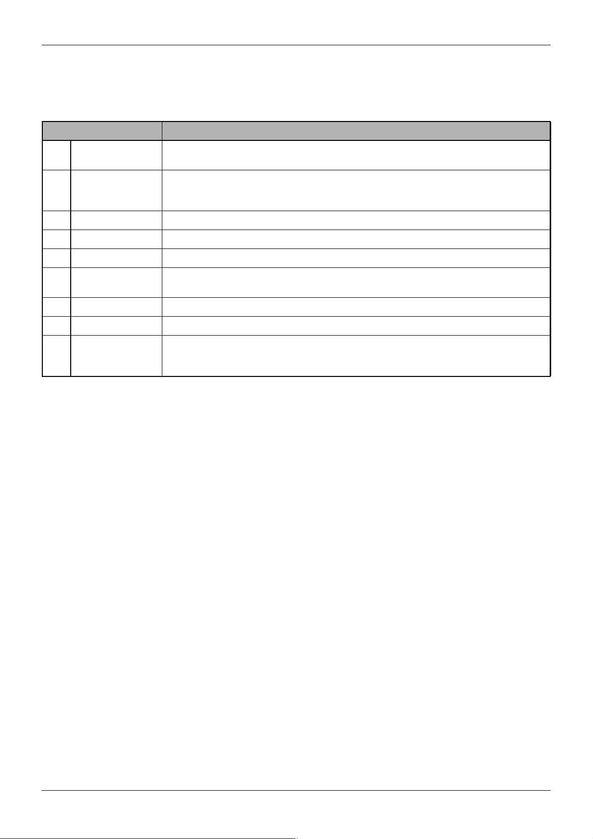
SUMMARY OF MANUAL CONTENTS
Section Contents
1. General Engine model and engine number, external views, features, engine specifications,
maintenance, troubleshooting
2. Engine main parts General, rocker arms and rocker shaft, cylinder head, valves and valve springs, inlet manifold
and exhaust manifold, gear case and oil pump, timing gear, camshaft (valve camshaft and
injection pump camshaft), piston and connecting rod, crankshaft, cylinder block
3. Lubrication system General, oil filter and oil pressure switch
4. Fuel system General, fuel injection pump, injection nozzle
5. Governor system General, torque spring
6. Cooling system General, fan and fan belt, water pump, thermostat, water temperature gauge unit and
thermoswitch
7. Air cleaner Air cleaner
8. Electrical system General, starter, alternator and dynamo, glow plug, key-off stop system, glow timer system
9. Service
specifications and
standard
Periodic service chart, specifications and standards, tightening torque chart and sealant chart,
special tools
Table 1 Sections in the service manual
4 / 155
ENGLISH
Service Manual Mitsubishi L-Series diesel engines
Version 08/2004

TABLE OF CONTENTS
TABLE OF CONTENTS
GENERAL
1 ENGINE MODEL AND ENGINE NUMBER........................................................................ 12
1.1 Model, classification and use ................................................................................................. 12
1.2 Engine model embossment and engine number stamp......................................................... 12
2 EXTERNAL VIEW ..................................................................................................................... 14
2.1 Engine L2............................................................................................................................... 14
2.2 Engine L3............................................................................................................................... 15
3FEATURES................................................................................................................................. 16
3.1 Aim of development ............................................................................................................... 16
3.2 Features of the new series..................................................................................................... 16
4 SPECIFICATIONS..................................................................................................................... 18
5 MAINTENANCE......................................................................................................................... 19
5.1 Engine oil and oil filter............................................................................................................ 19
5.2 Retightening the cylinder head bolts...................................................................................... 21
5.3 Adjusting the valve clearance ................................................................................................22
5.4 Adjusting the fan belt tension................................................................................................. 23
5.5 Bleeding air from the fuel system........................................................................................... 23
5.6 Replacing the fuel filter .......................................................................................................... 24
5.7 Checking and adjusting injection timing................................................................................. 26
5.8 Adjusting the engine speeds..................................................................................................27
5.9 Checking and adjustment of nozzles ..................................................................................... 28
6 TROUBLESHOOTING ............................................................................................................. 31
6.1 Hints on using the trouble-diagnosis chart............................................................................. 31
6.2 Hard starting .......................................................................................................................... 32
6.3 Knocking ................................................................................................................................ 33
6.4 Overheating ........................................................................................................................... 34
6.5 Black-smoky exhaust ............................................................................................................. 35
6.6 Unsteady idling ...................................................................................................................... 36
6.7 Low output ............................................................................................................................. 37
ENGINE MAIN PARTS
7GENERAL.................................................................................................................................... 40
7.1 Specifications......................................................................................................................... 40
7.2 Special Tools ......................................................................................................................... 41
8 ROCKER ARMS AND ROCKER SHAFT........................................................................... 42
8.1 Disassembly........................................................................................................................... 42
8.2 Removal and installation........................................................................................................ 43
8.3 Inspection............................................................................................................................... 43
9 CYLINDER HEAD ..................................................................................................................... 44
9.1 Disassembly........................................................................................................................... 44
9.2 Removal................................................................................................................................. 45
9.3 Inspection and Repair ............................................................................................................ 46
9.4 Replacement of valve guide...................................................................................................46
Service Manual Mitsubishi L-Series diesel engines
Version 08/2004
ENGLISH
5 / 155

TABLE OF CONTENTS
9.5 Repair of valve seat ............................................................................................................... 47
9.6 Installation.............................................................................................................................. 48
10 VALVES AND VALVE SPRINGS ......................................................................................... 49
10.1 Disassembly........................................................................................................................... 49
10.2 Removal................................................................................................................................. 50
10.3 Inspection and repair ............................................................................................................. 50
10.4 Installation.............................................................................................................................. 51
11 INLET MANIFOLD AND EXHAUST MANIFOLD............................................................. 52
11.1 Disassembly........................................................................................................................... 52
11.2 Inspection............................................................................................................................... 52
12 GEAR CASE AND OIL PUMP............................................................................................... 54
12.1 Disassembly........................................................................................................................... 54
12.2 Removal................................................................................................................................. 55
12.3 Inspection............................................................................................................................... 55
12.4 Replacement of front oil seal ................................................................................................. 56
12.5 Replacement of governor shaft bushings .............................................................................. 56
12.6 Inspection of governor system ...............................................................................................57
12.7 Disassembly and reassembly of governor levers .................................................................. 57
12.8 Installation of gear case assembly......................................................................................... 58
13 TIMING GEARS ......................................................................................................................... 59
13.1 Disassembly........................................................................................................................... 59
13.2 Removal................................................................................................................................. 60
13.3 Inspection............................................................................................................................... 60
13.4 Installation of timing gears ..................................................................................................... 61
14 CAMSHAFTS (VALVE AND INJECTION PUMP)............................................................ 62
14.1 Disassembly........................................................................................................................... 62
14.2 Removal of Valve Camshaft .................................................................................................. 63
14.3 Inspection............................................................................................................................... 64
14.4 Installation.............................................................................................................................. 65
15 PISTON AND CONNECTION ROD...................................................................................... 66
15.1 Disassembly........................................................................................................................... 66
15.2 Removal................................................................................................................................. 67
15.3 Inspection............................................................................................................................... 68
15.4 Installation.............................................................................................................................. 69
16 CRANKSHAFT........................................................................................................................... 73
16.1 Disassembly........................................................................................................................... 73
16.2 Removal................................................................................................................................. 74
16.3 Inspection............................................................................................................................... 74
16.4 Replacement of crankshaft rear oil seal................................................................................. 76
16.5 Installation.............................................................................................................................. 77
17 CYLINDER BLOCK .................................................................................................................. 78
17.1 Disassembly........................................................................................................................... 78
17.2 Inspection............................................................................................................................... 79
17.3 Reboring of cylinder ............................................................................................................... 79
LUBRICATION SYSTEM
6 / 155
ENGLISH
Service Manual Mitsubishi L-Series diesel engines
Version 08/2004

18 GENERAL.................................................................................................................................... 82
18.1 Specification........................................................................................................................... 82
18.2 Special tools........................................................................................................................... 82
19 OIL FILTER AND OIL PRESSURE SWITCH.................................................................... 83
19.1 Disassembly........................................................................................................................... 83
19.2 Removal and installation........................................................................................................ 84
19.3 Inspection............................................................................................................................... 84
FUEL SYSTEM
20 GENERAL.................................................................................................................................... 86
20.1 Specifications......................................................................................................................... 86
20.2 Disassembly........................................................................................................................... 88
21 FUEL INJECTION PUMP........................................................................................................ 89
21.1 Disassembly........................................................................................................................... 89
21.2 Inspecting the injection pump while operating the engine ..................................................... 90
21.3 Removal................................................................................................................................. 90
21.4 Disassembly........................................................................................................................... 90
21.5 Inspection............................................................................................................................... 91
21.6 Reassembly of plunger .......................................................................................................... 91
21.7 Reassembly of delivery valve ................................................................................................91
22 INJECTION NOZZLE ............................................................................................................... 92
22.1 Disassembly........................................................................................................................... 92
22.2 Removal................................................................................................................................. 92
22.3 Disassembly........................................................................................................................... 93
22.4 Inspection............................................................................................................................... 94
22.5 Assembly ............................................................................................................................... 94
22.6 Adjustment ............................................................................................................................. 94
22.7 Installation.............................................................................................................................. 95
GOVERNOR SYSTEM
23 GENERAL.................................................................................................................................... 98
23.1 Specification........................................................................................................................... 98
23.2 Disassembly........................................................................................................................... 99
24 TORQUE SPRING................................................................................................................... 100
24.1 Installation of torque spring set ............................................................................................ 100
24.2 Assembling the torque spring set......................................................................................... 100
24.3 Single spring type ................................................................................................................ 101
24.4 Inspection............................................................................................................................. 102
24.5 Removal and installation...................................................................................................... 103
COOLING SYSTEM
25 GENERAL.................................................................................................................................. 106
25.1 Specifications....................................................................................................................... 106
25.2 Disassembly......................................................................................................................... 107
26 FAN AND FAN BELT............................................................................................................. 108
26.1 Fan belt inspection............................................................................................................... 108
26.2 Fan inspection...................................................................................................................... 108
Service Manual Mitsubishi L-Series diesel engines
Version 08/2004
ENGLISH
7 / 155

27 WATER PUMP ......................................................................................................................... 109
27.1 Removal and installation...................................................................................................... 109
27.2 Inspection............................................................................................................................. 109
28 THERMOSTAT......................................................................................................................... 110
28.1 Removal and installation...................................................................................................... 110
28.2 Inspection............................................................................................................................. 110
29 WATER TEMPERATURE GAGE UNIT AND THERMOSWITCH.............................. 111
29.1 Inspection of water temperature gage unit........................................................................... 111
29.2 Inspection of thermoswitch .................................................................................................. 111
AIR CLEANER
30 AIR CLEANER ......................................................................................................................... 114
30.1 Disassembly......................................................................................................................... 114
30.2 Inspection............................................................................................................................. 115
ELECTRICAL SYSTEM
31 GENERAL.................................................................................................................................. 118
31.1 Specifications....................................................................................................................... 118
31.2 Wiring diagrams ................................................................................................................... 120
32 STARTER .................................................................................................................................. 122
32.1 Structure .............................................................................................................................. 122
32.2 Inspection (assembly) .......................................................................................................... 123
32.3 Disassembly......................................................................................................................... 125
32.4 Inspection............................................................................................................................. 126
32.5 Assembly and adjustment.................................................................................................... 128
33 ALTERNATOR AND DYNAMO........................................................................................... 129
33.1 Structure .............................................................................................................................. 129
33.2 Dynamo................................................................................................................................ 130
33.3 Inspection of the alternator (installed on the engine) ........................................................... 130
33.4 Output inspection ................................................................................................................. 131
33.5 Removal............................................................................................................................... 131
33.6 Disassembly of alternator .................................................................................................... 131
33.7 Inspection............................................................................................................................. 132
33.8 Installation............................................................................................................................ 135
33.9 Alternator and regulator ....................................................................................................... 135
34 GLOW PLUG ............................................................................................................................ 137
34.1 Removal............................................................................................................................... 137
34.2 Inspection............................................................................................................................. 137
34.3 Installation............................................................................................................................ 137
35 KEY-OFF STOP SYSTEM .................................................................................................... 138
35.1 General ................................................................................................................................ 138
35.2 Control timer unit.................................................................................................................. 138
35.3 Fuel cutoff solenoid (ETS type)............................................................................................ 138
35.4 Fuel cutoff solenoid (ETR type) ........................................................................................... 139
36 GLOW TIMER SYSTEM........................................................................................................ 141
36.1 General ................................................................................................................................ 141
8 / 155
ENGLISH
Service Manual Mitsubishi L-Series diesel engines
Version 08/2004

36.2 Glow timer............................................................................................................................ 141
36.3 Glow relay ............................................................................................................................ 141
SERVICE DATA
37 PERIODIC INSPECTION CHART....................................................................................... 144
37.1 Periodic service chart........................................................................................................... 144
38 SPECIFICATIONS AND MAINTENANCE STANDARDS............................................ 145
38.1 Engine Main Parts................................................................................................................ 145
38.2 Lubrication System .............................................................................................................. 148
38.3 Fuel System ......................................................................................................................... 148
38.4 Governor System ................................................................................................................. 149
38.5 Cooling System.................................................................................................................... 149
38.6 Electrical System ................................................................................................................. 150
39 TIGHTENING TORQUE CHART AND SEALANT CHART......................................... 152
39.1 Tightening Torque for Main Bolts......................................................................................... 152
39.2 Tightening Torque for Common Bolts and Nuts................................................................... 152
39.3 Tightening Torque for Common Plugs ................................................................................. 153
39.4 Sealant Chart ....................................................................................................................... 153
40 SPECIAL TOOLS .................................................................................................................... 154
Service Manual Mitsubishi L-Series diesel engines
Version 08/2004
ENGLISH
9 / 155

10 / 155
ENGLISH
Service Manual Mitsubishi L-Series diesel engines
Version 08/2004

GENERAL
Service Manual Mitsubishi L-Series diesel engines
Version 08/2004
ENGLISH
11 / 155
ENGINE MODEL AND ENGINE NUMBER GENERAL
GENERAL
1 ENGINE MODEL AND
ENGINE NUMBER
1.1 Model, classification and use
1.1.1 Engine model
Model Application Use
L2A 11,12 - For Agricultural
L2C
L2B 31, 32 - For Industrial
L3A
L3C 61, 62 - For Export only
L3E
Table 1 Engine model and usage
1.1.2 Engine model and application codes
L 3 C – 11 A
L – Name of series (L: Lightweight engine)
3 – Number of cylinders (2: two, 3: three)
C – Cylinder bore
• A: ø65, C: ø70,
• E: ø76
11 – Application
• 11: Agricultural, 31: Industrial,
• 61: For export only
A – Subdivision of specification
t
1.2 Engine model embossment and engine number stamp
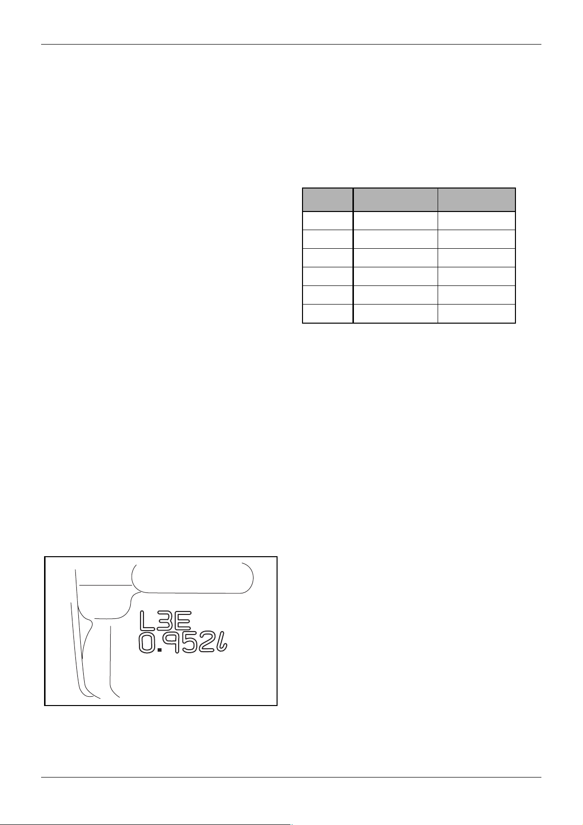
1.2.1 Embossment of engine model and
cylinder volume
Figure 1 Engine model and cylinder volume
12 / 155
ENGLISH
The engine model and cylinder volume are embossed
on the side of injection pump mounting portion of the
cylinder block.
Service Manual Mitsubishi L-Series diesel engines
Version 08/2004
GENERAL
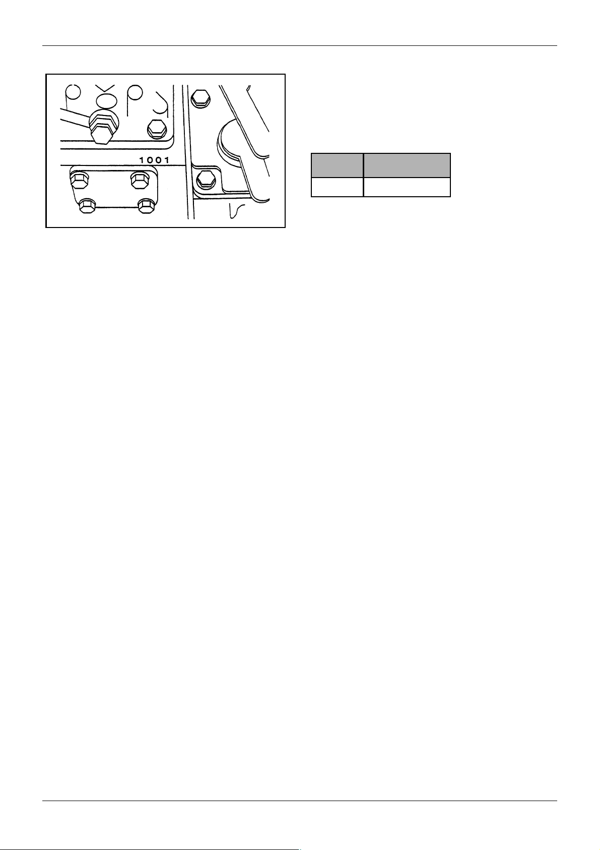
Figure 2 Engine number
ENGINE MODEL AND ENGINE NUMBER
1.2.2 Engine number stamp
The engine number is stamped on the injection pump
mounting portion of the cylinder block (on the upper
side of the tie rod cover). It is a serial number beginning
with 1001 shown as below.
Number Engine model
1001 - (ALL models)
Table 2 Engine number stamp
Service Manual Mitsubishi L-Series diesel engines
Version 08/2004
ENGLISH
13 / 155

EXTERNAL VIEW GENERAL
GENERAL
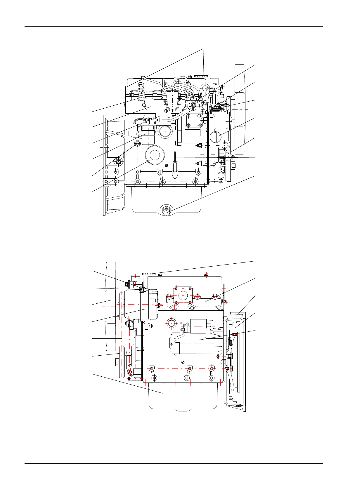
2 EXTERNAL VIEW
2.1 Engine L2
Engine hangers
Air vent screw
Water pump
Fuel injection pump
Fuel injector
Air inlet cover
Stop solenoid
Fuel filter
Side oil filler
Coolant drain plug
Oil pressure switch
Oil filter
REAR
Thermostat housing
Thermoswitch
Alternator
Fan
V-b elt
Dipstick
Oil drain plug
FRONT
RIGHT SIDE VIEW
Top oil filler
Exhaust manifold
Flywheel housing
Flywheel
Starter
14 / 155
Crankshaft pulley
Oil pan
FRONT
LEFT SIDE VIEW
ENGLISH
REAR
Service Manual Mitsubishi L-Series diesel engines
Version 08/2004
GENERAL
EXTERNAL VIEW
2.2 Engine L3
Fuel injector
Air inlet cover
Stop solenoid
Fuel filter
Coolant drain plug
Oil filter
REAR
Engine hangers
Air vent screw
Water pump
Fuel injection pump
Side oil filler
Oil pressure switch
Dipstick
Oil drain plug
FRONT
Thermostat housing
Thermoswitch
Fan
Alternator
V-belt
Crankshaft pulley
Oil pan
RIGHT SIDE VIEW
Top oil filler
Exhaust manifold
Flywheel housing
Flywheel
Starter
FRONT
Service Manual Mitsubishi L-Series diesel engines
Version 08/2004
LEFT SIDE VIEW
ENGLISH
REAR
15 / 155
FEATURES GENERAL
GENERAL
3FEATURES
3.1 Aim of development
The L-series designs are compact, lightweight engines
suitable for superseding gasoline engines to power
lawn mowers, vehicles, etc. The high-speed (3600 min
1
continuous) engines are also available for generators,
welders, and marine use. The L series are the smallest
and the lightest water-cooled diesel engines in the
world.
3.2 Features of the new series
3.2.1 Small and lightweight engine
The new L-series are 10 to 20% lighter in weight and
15 to 20% smaller in contour volume than the same
class of competitor’s engines.
-
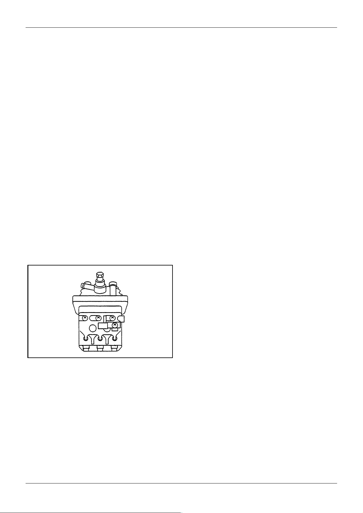
Figure 3 Injection pump
3.2.2 Low noise and economical fuel
consumption
Low noise and economical fuel consumption are
attained by the well designed cylinder block
construction (having curved side faces), the rearranged
combustion chambers, and the compacted fuel
injection system.
3.2.3 Easy starting
The engine can be started instantly only by keeping the
starting switch key in the ON position for about 6
seconds to feed electric current to the glow plugs
automatically (For engines with the automatic glow plug
system). The new governor mechanism also
contributes to easy engine start, by increasing the
amount of fuel injection and delaying injection timing,
without moving the throttle lever to the “full throttle”
position.
16 / 155
ENGLISH
Service Manual Mitsubishi L-Series diesel engines
Version 08/2004
GENERAL
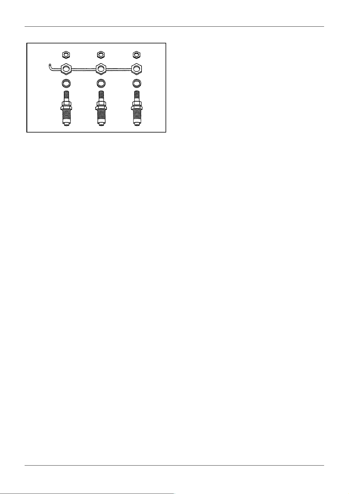
Figure 4 Nozzle holders and return pipe
FEATURES
3.2.4 Multipurpose engine
The L-series engine can be equipped with various
kinds of optional devices.
Ex.
• Key-OFF stop system (Fuel cutoff valve)
• Torque spring
• Manual stop lever
Service Manual Mitsubishi L-Series diesel engines
Version 08/2004
ENGLISH
17 / 155
SPECIFICATIONS GENERAL
GENERAL
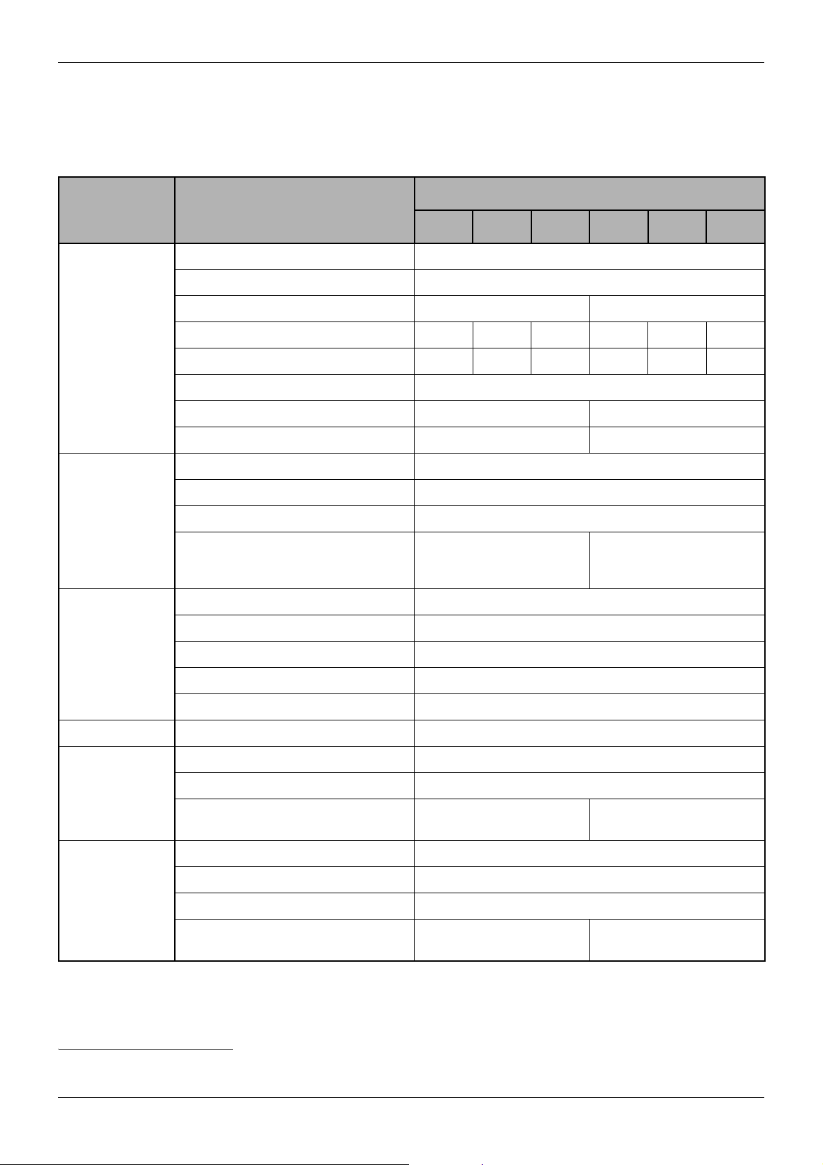
4 SPECIFICATIONS
System Item
Type 4-cycle, water-cooled, vertical, overhead valve, diesel engine
Combustion chamber Swirl chamber type
No. of cylinders 2 3
ENGINE
PROPER
LUBRICATING
SYSTEM
Bore x Stroke (mm) 65x70 70x70 76x70 65x70 70x70 76x70
Total displacement (l ) 0.464 0.538 0.635 0.696 0.808 0.952
Compression ratio 23
Firing order 1 - 2 1 - 3 - 2
Dry weight (kg) 61 75
Lubricating method Forced lubrication
Oil pump Gear type
Oil filter Paper element type
Oil capacity:
FULL level/EMPTY level (l )
(Exclusive of oil filter capacity 0.5 l )
1
Model
L2A L2C L2E L3A L3C L3E
2.4/1.4 3.0/1.5 or 3.6/1.8 or 4.8/3.0
Fuel injection pump Bosch type NC
Nozzle Throttle type
FUEL SYSTEM
INTAKE SYSTEM Air cleaner Paper-element type or Oil-bath type
COOLING
SYSTEM
ELECTRICAL
SYSTEM
Fuel injection pressure 140 kgf/cm
Fuel to be used Diesel fuel; see chapter 7
Governor Centrifugal weight type
Cooling method Forced circulation of water
Water pump Centrifugal type
Coolant capacity (l)
(Engine proper only)
Starter (V - kW) Solenoid shift type (12-1.2 or 12-1.6 or 12-1.7)
Alternator (V - A) AC generator (12-40)
Glow plug Sheathed type
Battery
(capacity depends on application)
12V, 45 Ah or more 12V, 60 Ah or more
1.2 1.8
2
(1,991 psi) [13,729 kPa]
Table 3 Specifications
1 All specifications are subject to change without any prior notice.
18 / 155
ENGLISH
Service Manual Mitsubishi L-Series diesel engines
Version 08/2004
GENERAL
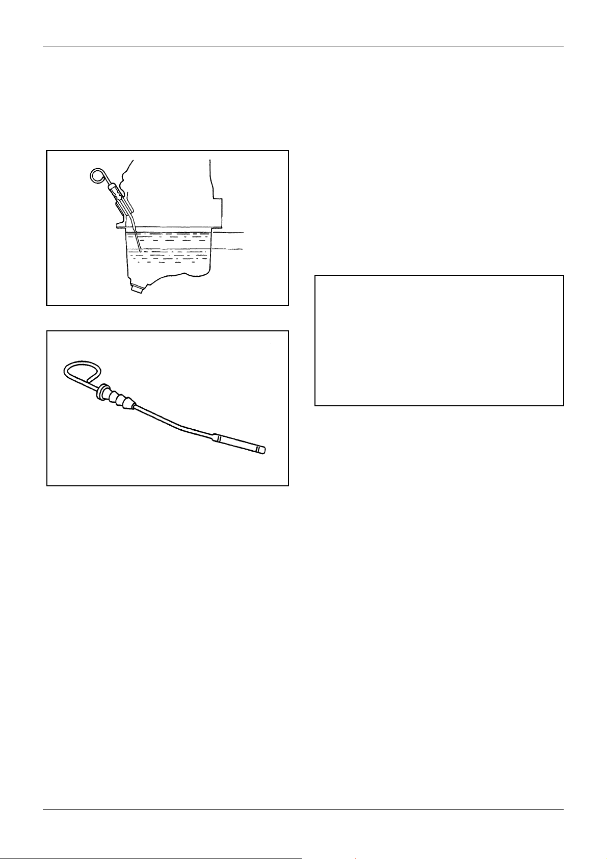
Figure 5 Checking oil level
MAINTENANCE
GENERAL
5 MAINTENANCE
5.1 Engine oil and oil filter
5.1.1 Checking and correcting the engine
oil level
Procedure
1. Place the engine horizontally.
2. Check the oil level with the oil level gage. If the oil
level has fallen to the lower limit, add oil up to the
upper limit.
3. Check the oil level before (everyday) operation of
the engine.
CAUTION
a. Whenever oil is added, check the oil level again
after waiting for about 1 minute.
b. When adding oil, use only the same engine oil as
used in the engine.
c. When checking the oil level in an engine which
has not been used for long time, check the oil
level again after running the engine for a few
minutes.
Figure 6 Oil level gage
5.1.2 Oil change intervals
Change the oil and the oil filter after initial 50 service
hour of a new engine and, thereafter, every 100 hours
of operation or once a year (whatever comes first).
Except generator application, 250 hours or once a year
(whatever comes first) can be applied for industrial and
marine application.
5.1.3 Engine oil to be used
Engine oil must conform to the API classification and
viscosity number specified in the table below.
Service Manual Mitsubishi L-Series diesel engines
Version 08/2004
ENGLISH
19 / 155

MAINTENANCE GENERAL
API
classification
Class CF
or CF-4
Atm. temperature Viscosity
Above 20°C [68°F] SAE30
5° to 20°C [41 to
68°F]
Below 5°C [41°F] SAE10W-30
All seasons SAE10W-30
SAE20
Table 4 API classification
5.1.4 Replacing the oil filter
When replacing the oil filter, use only the genuine
replacement filter.
Figure 7 Oil filter
5.1.5 Changing the oil
To change oil, first warm up the engine and remove the
drain plug to let oil drain completely. Put back the drain
plug and refill the oil pan with fresh engine oil through
the oil filler.
Tightening torque N·m (kgf·m) [lbf·ft]
Description Standard
Oil pan drain plug
tightening torque
Table 5 Tightening torque
Oil capacity (Upper
limit/Lower limit)
(excluding 0.5 l of
oil filter capacity)
1 [U.S.gal]
49.0 to 58.8 (5.0 to 6.0)
[36.17 to 43.40]
L2 L3
2.4/1.4
[0.6341/
0.3699]
Ordinary type 3.0/1.5
[0.7926/0.3963]
Deep type 3.6/1.8
[0.9511/0.4756] or
4.8/3.0 [1.2682/
0.7926]
20 / 155
ENGLISH
Table 6 Oil capacity
5.1.6 Replacing the oil filter
Procedure
1. Remove the oil filter with a filter wrench or the like.
Service Manual Mitsubishi L-Series diesel engines
Version 08/2004
GENERAL
MAINTENANCE
2. Thoroughly clean the filter mounting surface of the
filter bracket. Install the new filter with the O-ring
coated with engine oil and tighten securely by
hand.
Unit: N·m (kgf·m) [lbf·ft]
Tightening torque 10.8 to 12.7 (1.1 to 1.3) [7.96 to 9.40]
Table 7 Tightening torque
CAUTION
Be careful not to twist the O-ring.
3. Run the engine for several minutes and make sure
that no oil leaks.
4. After stopping the engine, check the oil level. If
necessary, add oil.
M10 bolt: 73.5 to 83.4 N·m (7.5 to 8.5 kgf·m)
[54.25 to 61.48 lbf·ft]
M8 bolt: 19.6 to 29.4 N·m (2.0 to 3.0 kgf·m)
[14.47 to 21.70 lbf·ft]
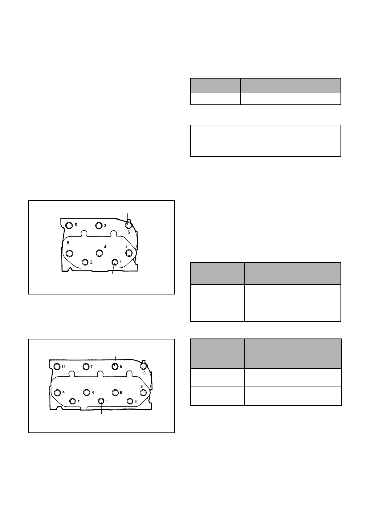
Figure 8 Cylinder head bolt tightening sequence
(L2)
M10 bolt: 73.5 to 83.4 N·m (7.5 to 8.5 kgf·m)
[54.25 to 61.48 lbf·ft]
5.2 Retightening the cylinder head
bolts
When retightening the cylinder head bolts, drain out
coolant, loosen the bolts slightly, and then retighten the
bolts to the specified torque in the numerical order
illustrated at right.
Tightening
torque
M10 bolt 73.5 to 83.4 (7.5 to 8.5)
M8 bolt 19.6 to 29.4 (2.0 to 3.0)
Table 8 Tightening torque
Rocker stay
tightening
torque
M10 bolt 73.5 to 83.4 (7.5 to 8.5)
Unit: N·m (kgf·m) [lbf·ft]
[54.25 to 61.48]
[14.47 to 21.70]
Unit: N·m (kgf·m) [lbf·ft]
[54.25 to 61.48]
M8 bolt: 19.6 to 29.4 N·m (2.0 to 3.0 kgf·m)
[14.47 to 21.70 lbf·ft]
Figure 9 Cylinder head bolt tightening sequence
(L3)
Service Manual Mitsubishi L-Series diesel engines
Version 08/2004
Table 9 Rocker stay tightening torque
The rocker assembly (the rocker arms, shaft and stays)
is to be kept removed when the cylinder head bolts are
retightened.
ENGLISH
M8 bolt 19.6 to 29.4 (2.0 to 3.0)
[14.47 to 21.70]
21 / 155
MAINTENANCE GENERAL
5.3 Adjusting the valve clearance
CAUTION
Be sure to retighten the cylinder head bolts before
adjusting the valve clearance.
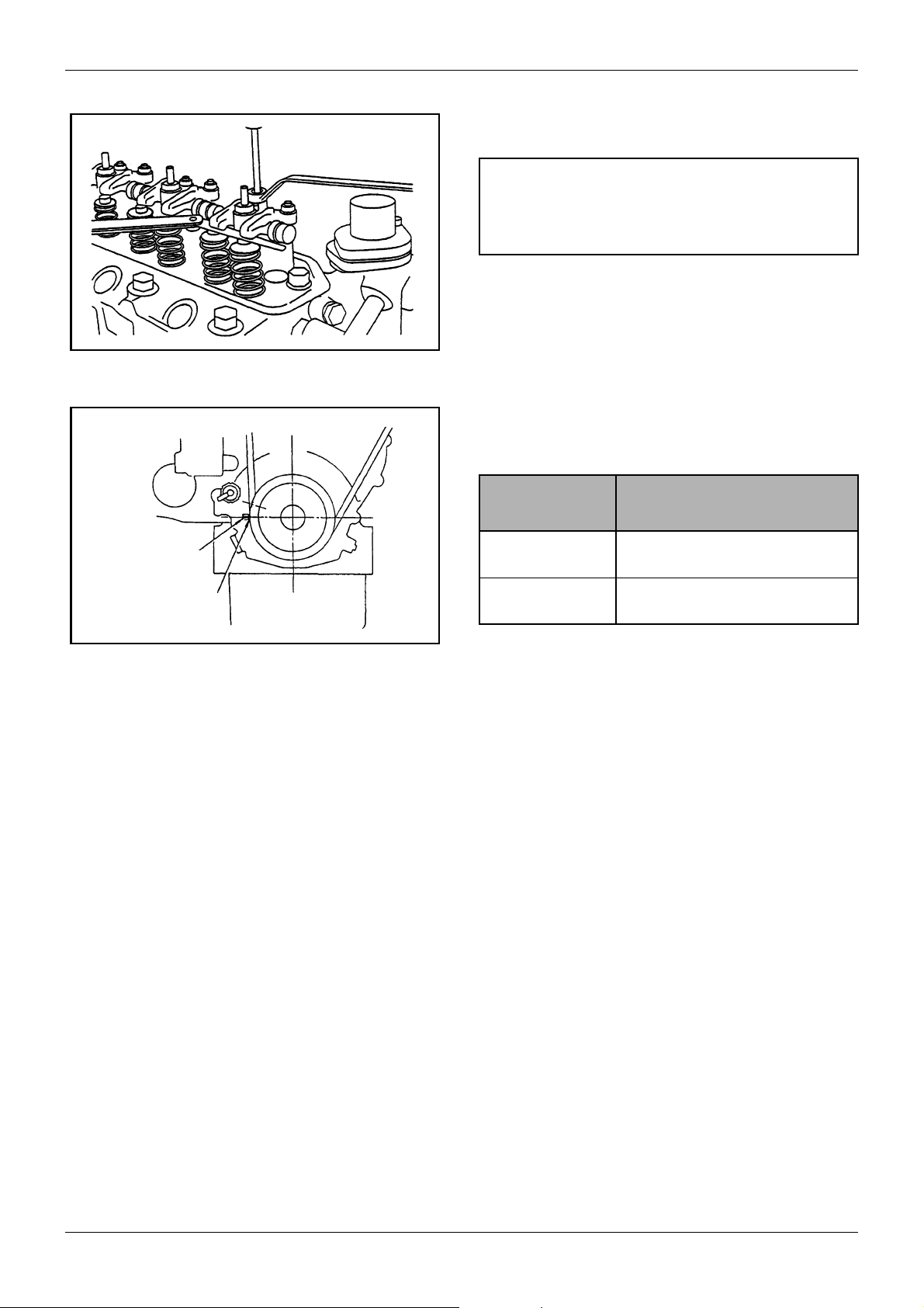
Figure 10 Adjusting valve clearance
Procedure
1. Set the cylinder to be adjusted to the top dead
center of compression stroke.
Mark on
gear case
TDC mark on
crankshaft pulley
Figure 11 Timing mark
Tightening
torque
M10 bolt 73.5 to 83.4 (7.5 to 8.5)
M8 bolt 19.6 to 29.4 (2.0 to 3.0)
Table 10 Tightening torque
2. The top dead center of compression stroke can be
obtained by aligning the TDC (Top Dead Center)
mark (notch) on the crankshaft pulley with the
mark on the gear case.
3. First align the TDC mark for the No. 1 cylinder.
Confirm that the valves do not move up and down
when the crankshaft is turned about 20° in normal
direction of rotation and in reverse direction.
4. When setting the top dead center for the No. 2
cylinder and that for the No. 3 cylinder, perform as
follows:
a L2 (Two-cylinder engine)
Turn the crankshaft 180° clockwise from TDC
(Top Dead Center) of the No. 1 cylinder, to set
the No. 2 cylinder TDC.
b L3 (Three-cylinder engine)
Turn the crankshaft 240° clockwise from TDC
of the No. 2 cylinder, to set the No. 3 cylinder
TDC. Further, turn the crankshaft 240°
clockwise from No. 3 cylinder TDC and
reconfirm the position of the No. 2 cylinder
TDC.
Unit: N·m (kgf·m) [lbf·ft]
[54.25 to 61.48]
[14.47 to 21.70]
22 / 155
ENGLISH
Service Manual Mitsubishi L-Series diesel engines
Version 08/2004
GENERAL
Approx: 10 mm
[0.3937 in.]
(98 N (10 kgf) [22 lbf]
of thumb force)
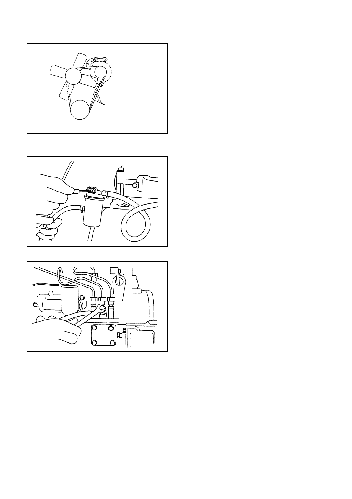
Figure 12 Adjusting fan belt tension
Figure 13 Fuel filter air bleeding
MAINTENANCE
5.4 Adjusting the fan belt tension
To check if the belt tension is appropriate, press the
belt at a midpoint between the alternator pulley and
crankshaft pulley with your thumb, and check that the
amount of belt deflection is about 10 mm [0.3937 in.]
(about 98 N (10 kgf) [22 lbf]).
5.5 Bleeding air from the fuel system
Procedure
1. Loosen the air vent screw on the fuel filter.
2. For engine without feed pump, fuel flows down and
enters the fuel filter, wait for fuel to overflow from
the air vent screw. Then tighten the air vent screw.
3. For engine with the electromagnetic fuel pump,
turn the starting switch key to the ON position to
feed fuel to the fuel filter. Loosen the air vent screw
on the filter and, after bleeding air, tighten the air
vent screw.
4. Loosen the air vent screw on the fuel injection
pump to let air bleed from the fuel pipe and fuel
injection pump.
5. Air in the injection pipes and nozzles is driven out
automatically by cranking the engine.
Figure 14 Fuel injection pump air bleeding
Service Manual Mitsubishi L-Series diesel engines
Version 08/2004
ENGLISH
23 / 155
MAINTENANCE GENERAL
5.6 Replacing the fuel filter
5.6.1 Cartridge type
Replace the cartridge type filter as an assembly if
accumulation of dust or water is in its element. Regular
replacement interval is every 500 service hours of
engine operation. Check the filter every 100 service
hours and, if necessary, replace early.
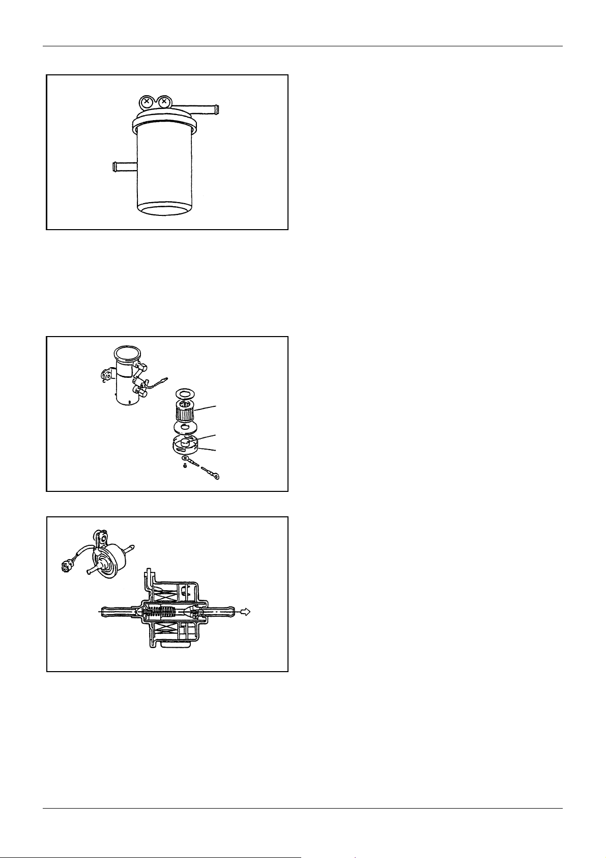
5.6.2 Separate type filter with cock
Close the filter cock, remove the ring nut, and take out
Figure 15 Cartridge type filter
the element from the inside of filter. Clean or replace
the element.
5.6.3 Fuel pump
The following three types of fuel pumps are available.
Which type of pump is to be used for an engine
depends upon engine specification.
Filter
Magnet
Cover
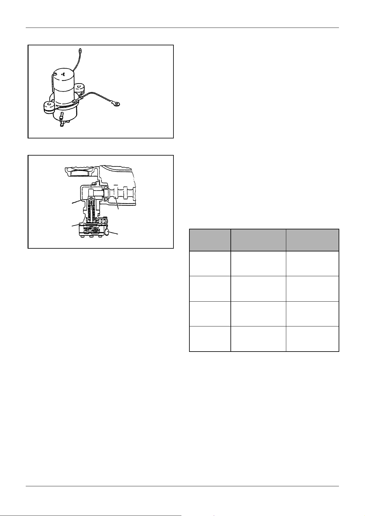
Figure 16 Plunger type (common) fuel pump
1. Plunger type electromagnetic pump
The plunger-type pumps are classified as the common, large-sized pump having a filter element or
as the compact lightweight, low-priced pump without filter element. Regardless of classification,
check the plunger-type pump for normal function
and make sure that it does not leak fuel. Only on
the pump with filter element, remove the cover and
clean or replace the filter element.
Figure 17 Plunger type (compact) fuel pump
24 / 155
ENGLISH
Service Manual Mitsubishi L-Series diesel engines
Version 08/2004
GENERAL
Figure 18 Diaphragm type fuel pump
Adapter
Camshaft, fuel
injection pump
Fuel pump
Primer lever
MAINTENANCE
2. Diaphragm type electromagnetic pump
The diaphragm type electromagnetic pump should
not be disassembled. Like the compact plungertype pump mentioned above, check the pump for
functions and fuel leak.
3. Mechanical type fuel pump
This type of fuel pump is installed with an adapter
on the rear-end side of the fuel injection pump
camshaft. As the camshaft rotates, the fuel pump
cam pushes the tappet to actuate the diaphragm of
the fuel pump. This type of fuel pump is provided
with a priming lever to allow manual feed to fuel.
Check the fuel pump for normal function and make
sure that it does not leak fuel or make unusual
noise.
Pump type Delivery flow
Shut-off
pressure
Figure 19 Mechanical type fuel pump
Plunger type
(common)
Plunger type
(compact)
Diaphragm
type
Mechanical
type
0.9 l
[0.24 U.S.gal]/ min
or more
0.4 l
[0.11 U.S.gal]/ min
or more
0.37 l
[0.10 U.S.gal]/ min
or more
0.255 l
[0.06 U.S.gal]/ min
or more
0.03 MPa
(0.35 kgf/cm2)
[4.98 psi]
0.03 MPa
(0.35 kgf/cm
[4.98 psi]
0.01 MPa
(0.15 kgf/cm
[2.13 psi]
0.01 MPa
(0.15 kgf/cm
[2.13 psi]
2
)
2
)
2
)
Table 11 Fuel pumps at 12V (electromagnetic
pumps only) and at 20°C [68°F]
5.6.4 Draining water from the water
sedimentator
For engine provided with a water sedimentator, remove
the filter ring nut involved and take out the cup. Wipe off
water and dust accumulated in the cup.
Service Manual Mitsubishi L-Series diesel engines
Version 08/2004
ENGLISH
25 / 155
MAINTENANCE GENERAL
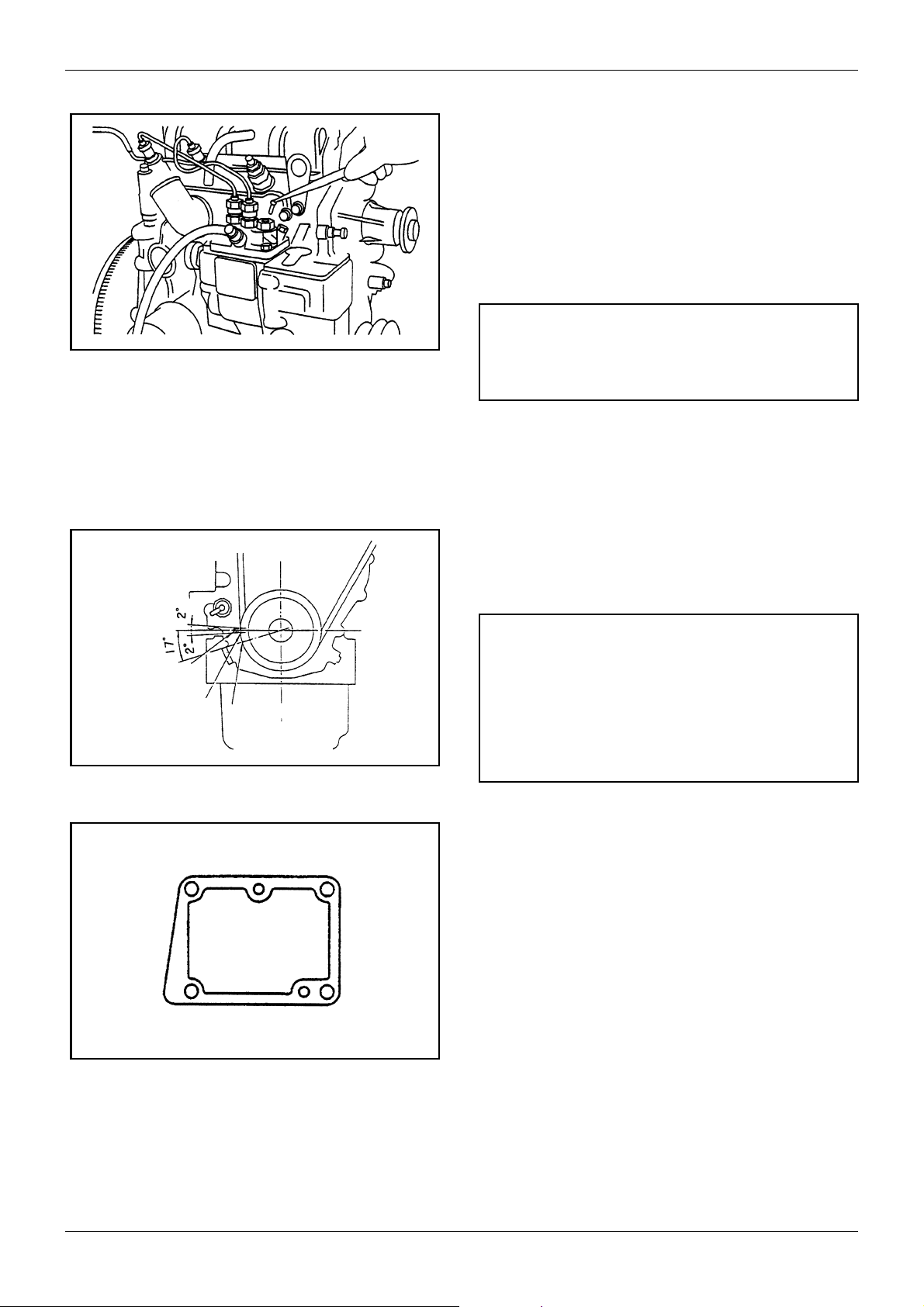
5.7 Checking and adjusting injection timing
To check and adjust injection timing, use the following
procedure:
1. Disconnect the No. 1 injection pipe.
2. Remove the No. 1 delivery valve from the injection
pump. Put back the valve holder only.
CAUTION
Figure 20 Removing delivery valve
Be sure to shut off the fuel feed before removing the
delivery valve.
3. Remove the tie-rod cover and disconnect the tie-
rod from the control rack.
4. Set the control rack to a midway position in the
working range.
5. Open the fuel feed pipe and make sure that fuel
flows from the delivery valve holder.
6. Turn the crankshaft in the direction of normal
rotation (clockwise) and find an instant that fuel
stops flowing from the delivery valve holder. This
instant is the real injection timing.
Mark on gear
case
IT mark on
pulley
Figure 21 Injection timing mark
Figure 22 Adjusting shim thickness
TDC mark
CAUTION
The standard injection timing differs with engine
specification and engine speed.
Check to see whether the real injection timing
coincides with the standard injection timing (whether
the IT mark on the crankshaft pulley aligns with the
mark on the gear case).
7. If they do not coincide with each other, adjust
thickness of the injection pump mounting shim.
Increasing or decreasing shim thickness by 0.1
mm [0.0039 in.] causes the real injection timing to
vary about 1°.
26 / 155
ENGLISH
Service Manual Mitsubishi L-Series diesel engines
Version 08/2004
GENERAL
Figure 23 Removing injection pump
MAINTENANCE
8. To remove the injection pump, first disconnect the
injection pipes and fuel feed pipe from the injection
pump. Then, remove the tie-rod cover and tie-rod.
Dismount the pump assembly. Reassembly
sequence of the pump is the reverse of
disassembly.
9. In the dusty place or when the engine is dirty,
removal of a delivery valve may cause dust to
enter into the injection pump. Under such
circumstances leave the delivery valve installed
and check injection timing using the following
procedure:
a Remove the tie-rod cover and disconnect the
tie-rod from the control rack.
b Set the control rack to a midway position in
the working range. Disconnect the injection
pipe from the No. 1 nozzle. Turn the
crankshaft gradually in the direction of normal
rotation until swelling of fuel is found at the
open end of the injection pipe. This instant is
the real injection timing, which will come
approx. 1° later than standard injection timing.
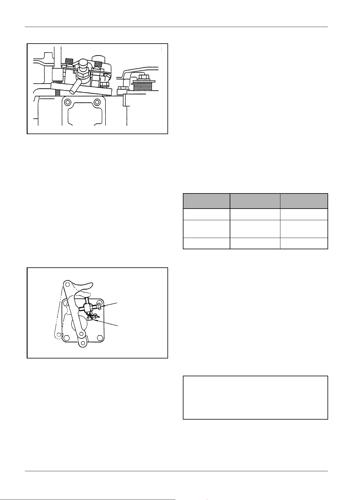
LOW-SPEED
set bolt
HIGH-SPEED
set bolt
Figure 24 HIGH-SPEED and LOW-SPEED set bolts
1
min-
Less than 2000 BTDC 15° BTDC 15°
200 to less than
3600
3600 or more BTDC 19° BTDC 19°
Table 12 Standard injection timing
Model L2 Model L3
BTDC 17° BTDC 17°
5.8 Adjusting the engine speeds
To adjust engine speed, remove the cooling fan and
install the safety cover over the fan to reduce the risk of
injury.
1. The upper limit of engine speed can be adjusted
with the HIGH-SPEED stopper bolt. This stopper
bolt has been set properly and sealed in the
factory before shipping of the engine. Never
attempt to open the seal unless it is necessary.
2. The lower limit of engine speed can be adjusted
with the LOW-SPEED stopper bolt.
3. Never remove the sealing cap unless it is
necessary to adjust the torque spring set.
Service Manual Mitsubishi L-Series diesel engines
Version 08/2004
CAUTION
Warm up the engine (until coolant temperature rises
up to 60°C [140°F] or above) before adjusting engine
speeds.
4. During running of the engine for speed adjustment,
ENGLISH
check the engine for gas leak, water leak, oil leak
and fuel leak.
27 / 155
MAINTENANCE GENERAL
5. After adjustment, perform engine acceleration and
deceleration test to confirm that the engine is free
from hunting and smoking.
5.9 Checking and adjustment of nozzles
To check and adjust the injection nozzles, use the
following procedure:
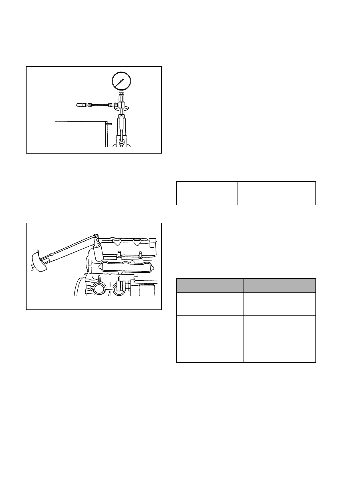
5.9.1 Injection start pressure
1. Remove the nozzle assembly to be tested from the
cylinder head and set the nozzle on the nozzle
tester.
Perform air bleeding by moving the tester handle
up and down.
Figure 25 Testing injection start pressure
2. Operate the handle at a rate of one discharge a
second or more and read the gage pressure of fuel
injected from the nozzle.
H25 to 29 N m
(2.5 to 3.0 kgf m)
[18.08 to 21.70 lbf ft]
Figure 26 Installing nozzle assembly
Injection start pressure 13.7 MPa
+1.0
- 0
+10
(140 kgf/cm
- 0
+142
[1992 psi]
- 0
2
)
Table 13 Start pressure
3. If reading of gage pressure exceeds the specified
range, disassemble the nozzle and adjust by using
the adjusting shim.
Increasing or decreasing shim thickness by 0.1
mm [0.0039 in.] will cause injection pressure to
vary about 0.98 MPa (10 kgf/cm2) [142 psi].
4. When reassembling the nozzle, use the following
values of tightening torque:
Nozzle Tightening torque
Nozzle tightening (to
cylinder head) torque
Nozzle retaining nut
tightening torque
Nozzle union collar
tightening torque
49.0 to 58.8 N·m
(5.0 to 6.0 kgf·m )
[36.17 to 43.40 lbf·ft]
34.3 to 39.2 N·m
(3.5 to 4.0 kgf·m)
[25.32 to 28.93 lbf·ft]
25 to29 N·m
(2.5 to 3.0 kgf·m)
[18.08 to 21.70 lbf·ft]
28 / 155
ENGLISH
Table 14 Tightening torque
Service Manual Mitsubishi L-Series diesel engines
Version 08/2004
GENERAL
MAINTENANCE
5.9.2 Chattering test
Operate the tester handle at a speed of about one
stroke per second.
1. Needle valve oscillation
If the fuel spray shows good atomization, making
intermittent sounds, and oscillations of the needle
valve are transmitted to the handle, then the nozzle is considered as normal.
Good
Bad
Figure 27 Chattering test
Good
Bad
Figure 28 After-spilling
Bad
Bad
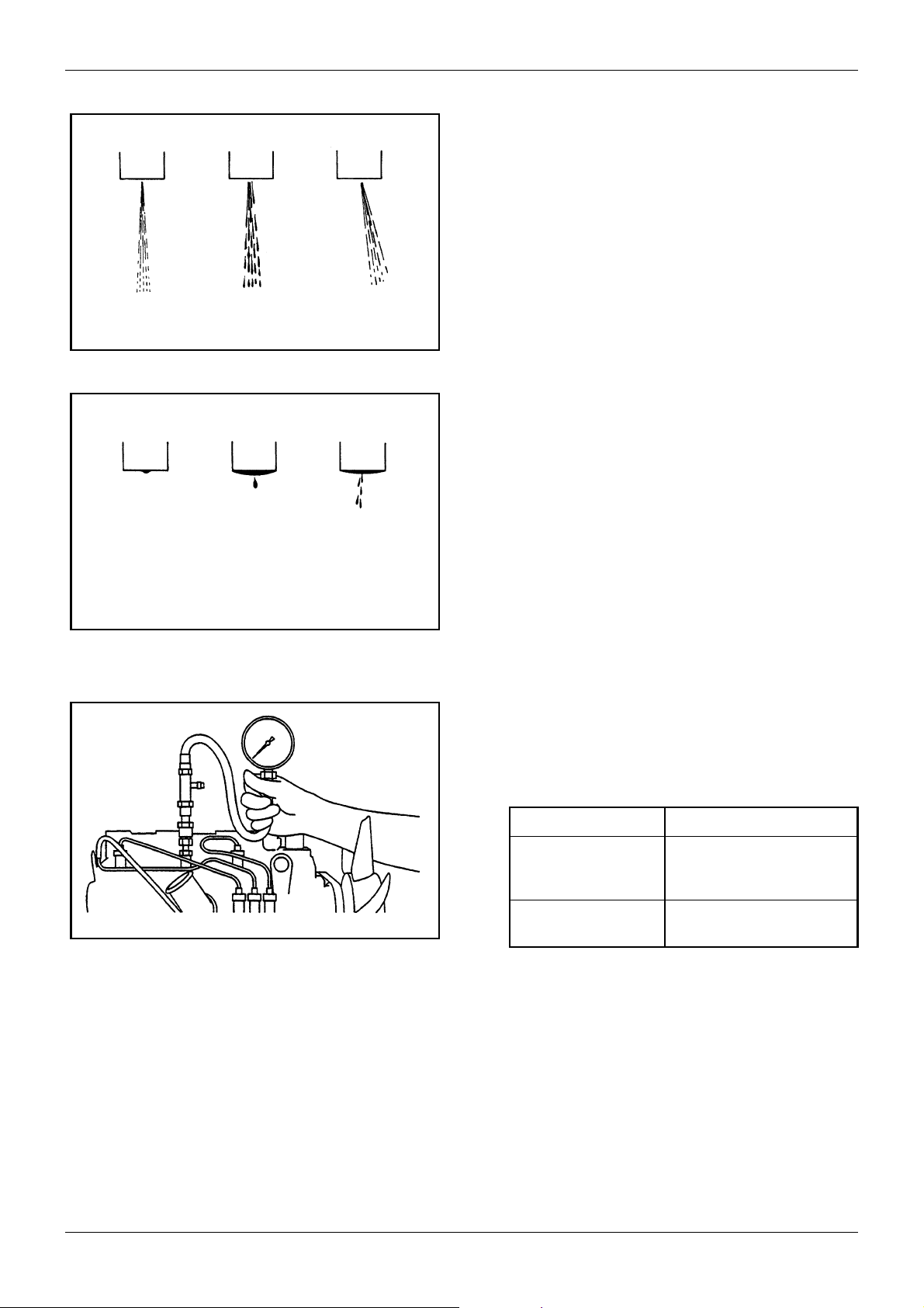
2. Shape of fuel spray
The nozzle should inject fuel spray straight in the
direction of its axis. A nozzle is defective if it does
not inject steadily or it injects fuel in several separate stripes.
A nozzle is defective if it spills fuel accumulated on
the bottom of the nozzle after chattering test. However, a very small drop of fuel remaining on the tip
of nozzle after chattering test may be regarded as
normal.
5.9.3 Injection Test
1. Operate the tester handle at a speed of 4 to 6
strokes per second.
2. A nozzle should inject fuel spray uniformly in the
shape of a cone.
5.9.4 Checking the compression pressure
Make sure of the following:
1. The engine oil level, air cleaner, starting motor, and
battery are well-conditioned.
Figure 29 Testing compression pressure
Service Manual Mitsubishi L-Series diesel engines
Version 08/2004
2. Warm up the engine to the coolant temperature of
Measure the compression pressure using the following
procedure:
1. The following are the conditions to perform test.
2. Pull the stop lever to the “non-injection” position.
3. Remove the glow plug from the cylinder to be
ENGLISH
Engine speed 250 to 280 min
Compression
pressure
Pressure difference
between cylinders
2.84 to 3.14 Mpa
(29 to 32 kgf/cm2)
[413 to 455 psi]
0.29 MPa (3 kgf/cm
[43 psi] or less
-1
2
)
Table 15 Conditions to perform test
50°C [122°F] or more.
tested. Set the compression gage adapter to that
cylinder and install the gage.
29 / 155

MAINTENANCE GENERAL
Special tool name Part No.
Compression gage
adapter
ST332270
Table 16 Tools
4. Crank the engine with the starting motor until a
stable reading of the compression gage is
obtained.
5. After reading the gage, remove the compression
gage and adapter. Put back the glow plug.
6. Check all cylinders using the same procedure
described above.
30 / 155
ENGLISH
Service Manual Mitsubishi L-Series diesel engines
Version 08/2004
 Loading...