


QnUDVCPU/LCPU User's Manual
(Data Logging Function)
-Q03UDVCPU
-Q04UDVCPU
-Q04UDPVCPU
-Q06UDVCPU
-Q06UDPVCPU
-Q13UDVCPU
-Q13UDPVCPU
-Q26UDVCPU
-Q26UDPVCPU
-L02CPU
-L02CPU-P
-L06CPU
-L06CPU-P
-L26CPU
-L26CPU-P
-L26CPU-BT
-L26CPU-PBT

SAFETY PRECAUTIONS
WARNING
CAUTION
Indicates that incorrect handling may cause hazardous conditions,
resulting in death or severe injury.
Indicates that incorrect handling may cause hazardous conditions,
resulting in minor or moderate injury or property damage.
(Read these precautions before using this product.)
Before using this product, please read this manual and the relevant manuals carefully and pay full attention
to safety to handle the product correctly.
In this manual, the safety precautions are classified into two levels: " WARNING" and " CAUTION".
Under some circumstances, failure to observe the precautions given under " CAUTION" may lead to
serious consequences.
Observe the precautions of both levels because they are important for personal and system safety.
Make sure that the end users read this manual and then keep the manual in a safe place for future
reference.
1
[Design Precautions]
Overcurrent or overvoltage protection of
the power supply module is activated.
The CPU module detects an error such as a
watchdog timer error by the self-diagnostic function.
All outputs are turned off All outputs are turned off
All outputs are turned off
All outputs are held or turned off
according to the parameter setting.
Q/L series module AnS/A series module
WARNING
● Configure safety circuits external to the programmable controller to ensure that the entire system
operates safely even when a fault occurs in the external power supply or the programmable controller.
Failure to do so may result in an accident due to an incorrect output or malfunction.
(1) Emergency stop circuits, protection circuits, and protective interlock circuits for conflicting
operations (such as forward/reverse rotations or upper/lower limit positioning) must be configured
external to the programmable controller.
(2) Machine OPR (Original Point Return) of the positioning function is controlled by two kinds of data:
an OPR direction and an OPR speed. Deceleration starts when the near-point watchdog signal
turns on. If an incorrect OPR direction is set, motion control may continue without deceleration. To
prevent machine damage caused by this, configure an interlock circuit external to the
programmable controller.
(3) When the CPU module detects an error during control by the positioning function, the motion slows
down and stops.
(4) The programmable controller stops its operation upon detection of the following status, and the
output status of the system will be as shown below.
Also, all outputs may be turned on if an error occurs in a part, such as an I/O control part, where
the programmable controller CPU cannot detect any error. To ensure safety operation in such a
case, provide a safety mechanism or a fail-safe circuit external to the programmable controller.
For a fail-safe circuit example, refer to the User's Manual (Hardware Design, Maintenance and
Inspection) for the CPU module used.
(5) Outputs may remain on or off due to a failure of a component such as a transistor in an output
circuit. Configure an external circuit for monitoring output signals that could cause a serious
accident.
● In an output circuit, when a load current exceeding the rated current or an overcurrent caused by a
load short-circuit flows for a long time, it may cause smoke and fire. To prevent this, configure an
external safety circuit, such as a fuse.
● Configure a circuit so that the programmable controller is turned on first and then the external power
supply. If the external power supply is turned on first, an accident may occur due to an incorrect output
or malfunction.
● Configure a circuit so that the external power supply is turned off first and then the programmable
controller. If the programmable controller is turned off first, an accident may occur due to an incorrect
output or malfunction.
● For the operating status of each station after a communication failure, refer to relevant manuals for
each network. Incorrect output or malfunction due to a communication failure may result in an
accident.
2
WARNING
● When changing data from a peripheral device connected to the CPU module during operation,
configure an interlock circuit in the program to ensure that the entire system will always operate safely.
For other controls to a running programmable controller (such as program modification or operating
status change), read relevant manuals carefully and ensure the safety before the operation.
Especially, in the case of a control from an external device to a remote programmable controller,
immediate action cannot be taken for a problem on the programmable controller due to a
communication failure. To prevent this, configure an interlock circuit in the program, and determine
corrective actions to be taken between the external device and CPU module in case of a
communication failure.
● An absolute position restoration by the positioning function may turn off the servo-on signal (servo off)
for approximately 20ms, and the motor may run unexpectedly. If this causes a problem, provide an
electromagnetic brake to lock the motor during absolute position restoration.
[Design Precautions]
CAUTION
● Do not install the control lines or communication cables together with the main circuit lines or power
cables. Keep a distance of 100mm or more between them. Failure to do so may result in malfunction
due to noise.
● During control of an inductive load such as a lamp, heater, or solenoid valve, a large current
(approximately ten times greater than normal) may flow when the output is turned from off to on.
Therefore, use a module that has a sufficient current rating.
● After the CPU module is powered on or is reset, the time taken to enter the RUN status varies
depending on the system configuration, parameter settings, and/or program size. Design circuits so
that the entire system will always operate safely, regardless of the time.
3
[Installation Precautions]
WARNING
● Shut off the external power supply (all phases) used in the system before mounting or removing a
module. Failure to do so may result in electric shock or cause the module to fail or malfunction.
[Installation Precautions]
CAUTION
● Use the programmable controller in an environment that meets the general specifications in the User's
Manual (Hardware Design, Maintenance and Inspection) for the CPU module used. Failure to do so
may result in electric shock, fire, malfunction, or damage to or deterioration of the product.
● To mount the module, while pressing the module mounting lever in the lower part of the module, fully
insert the module fixing projection(s) into the hole(s) in the base unit and press the module until it
snaps into place. Incorrect interconnection may cause malfunction, failure, or drop of the module.
When using the programmable controller in an environment of frequent vibrations, fix the module with
a screw. Tighten the screws within the specified torque range. Undertightening can cause drop of the
screw, short circuit, or malfunction. Overtightening can damage the screw and/or module, resulting in
drop, short circuit, or malfunction.
● When using an extension cable, connect it to the extension cable connector of the base unit securely.
Check the connection for looseness. Poor contact may cause incorrect input or output.
● When using an SD memory card, fully insert it into the SD memory card slot. Check that it is inserted
completely. Poor contact may cause malfunction.
● Securely insert an extended SRAM cassette into the cassette connector of a CPU module. After
insertion, close the cassette cover to prevent the cassette from coming off. Failure to do so may cause
malfunction.
● To interconnect modules, engage the respective connectors and securely lock the module joint levers
until they click.
● Do not directly touch any conductive parts and electronic components of the module. Doing so can
cause malfunction or failure of the module.
● Securely connect an extension cable to the connectors of a branch module and an extension module.
After connections, check that the cable is inserted completely. Poor contact may cause malfunction.
[Wiring Precautions]
WARNING
● Shut off the external power supply (all phases) used in the system before wiring. Failure to do so may
result in electric shock or cause the module to fail or malfunction.
● After installation and wiring, attach the included terminal cover to the module before turning it on for
operation. Failure to do so may result in electric shock.
4

[Wiring Precautions]
CAUTION
● Individually ground the FG and LG terminals of the programmable controller with a ground resistance
of 100 ohms or less. Failure to do so may result in electric shock or malfunction.
● Use applicable solderless terminals and tighten them within the specified torque range.
If any spade solderless terminal is used, it may be disconnected when a terminal block screw comes
loose, resulting in failure.
● Check the rated voltage and terminal layout before wiring to the module, and connect the cables
correctly. Connecting a power supply with a different voltage rating or incorrect wiring may cause a fire
or failure.
● Connectors for external devices must be crimped or pressed with the tool specified by the
manufacturer, or must be correctly soldered. Incomplete connections may cause short circuit, fire, or
malfunction.
● Securely connect the connector to the module. Poor contact may result in malfunction.
● Do not install the control lines or communication cables together with the main circuit lines or power
cables. Keep a distance of 100mm or more between them. Failure to do so may result in malfunction
due to noise.
● Place the cables in a duct or clamp them. If not, dangling cable may swing or inadvertently be pulled,
resulting in damage to the module or cables or malfunction due to poor contact.
● Check the interface type and correctly connect the cable. Incorrect wiring (connecting the cable to an
incorrect interface) may cause failure of the module and external device.
● Tighten the terminal block screws within the specified torque range. Undertightening can cause short
circuit, fire, or malfunction. Overtightening can damage the screw and/or module, resulting in drop,
short circuit, or malfunction.
● When disconnecting the cable from the module, do not pull the cable by the cable part. For the cable
with connector, hold the connector part of the cable. For the cable connected to the terminal block,
loosen the terminal screw. Pulling the cable connected to the module may result in malfunction or
damage to the module or cable.
● Prevent foreign matter such as dust or wire chips from entering the module. Such foreign matter can
cause a fire, failure, or malfunction.
● A protective film is attached to the top of the module to prevent foreign matter, such as wire chips,
from entering the module during wiring. Do not remove the film during wiring. Remove it for heat
dissipation before system operation.
● To use the high-speed counter function, ground the shield cable on the encoder side (relay box).
Failure to do so may cause malfunction.
● Mitsubishi Electric programmable controllers must be installed in control panels. Connect the main
power supply to the power supply module in the control panel through a relay terminal block.
Wiring and replacement of a power supply module must be performed by qualified maintenance
personnel with knowledge of protection against electric shock.
For wiring methods, refer to the User's Manual (Hardware Design, Maintenance and Inspection) for
the CPU module used.
5
[Startup and Maintenance Precautions]
WARNING
● Do not touch any terminal while power is on. Doing so will cause electric shock or malfunction.
● Correctly connect the battery connector. Do not charge, disassemble, heat, short-circuit, solder, or
throw the battery into the fire. Also, do not expose it to liquid or strong shock.
Doing so will cause the battery to produce heat, explode, ignite, or leak, resulting in injury and fire.
● Shut off the external power supply (all phases) used in the system before cleaning the module or
retightening the terminal block screws, connector screws, or module fixing screws. Failure to do so
may result in electric shock or cause the module to fail or malfunction.
[Startup and Maintenance Precautions]
CAUTION
● Before performing online operations (especially, program modification, forced output, and operating
status change) for the running CPU module from the peripheral device connected, read relevant
manuals carefully and ensure the safety. Improper operation may damage machines or cause
accidents.
● Do not disassemble or modify the modules. Doing so may cause failure, malfunction, injury, or a fire.
● Use any radio communication device such as a cellular phone or PHS (Personal Handy-phone
System) more than 25cm away in all directions from the programmable controller. Failure to do so
may cause malfunction.
● Shut off the external power supply (all phases) used in the system before mounting or removing a
module. Failure to do so may cause the module to fail or malfunction.
● Tighten the terminal block screws within the specified torque range. Undertightening can cause drop
of the component or wire, short circuit, or malfunction. Overtightening can damage the screw and/or
module, resulting in drop, short circuit, or malfunction.
● After the first use of the product (module, display unit, and terminal block), do not connect/disconnect
the product, do not mount/remove the module to/from the base unit, and do not insert/remove the
extended SRAM cassette to/from the CPU module more than 50 times (in accordance with IEC
61131-2). Exceeding the limit may result in malfunction.
● After the first use of the product, do not insert/remove the SD memory card to/from the CPU module
more than 500 times. Exceeding the limit may cause malfunction.
● Do not drop or apply shock to the battery to be installed in the module. Doing so may damage the
battery, causing the battery fluid to leak inside the battery. If the battery is dropped or any shock is
applied to it, dispose of it without using.
● Before handling the module, touch a conducting object such as a grounded metal to discharge the
static electricity from the human body. Failure to do so may cause the module to fail or malfunction.
● Before testing the operation by the positioning function, set a low speed value for the speed limit
parameter so that the operation can be stopped immediately upon occurrence of a hazardous
condition.
6
[Disposal Precautions]
CAUTION
● When disposing of this product, treat it as industrial waste. When disposing of batteries, separate
them from other wastes according to the local regulations. (For details on battery regulations in EU
member states, refer to the User's Manual (Hardware Design, Maintenance and Inspection) for the
CPU module used.)
[Transportation Precautions]
CAUTION
● When transporting lithium batteries, follow the transportation regulations. (For details on the regulated
models, refer to the User's Manual (Hardware Design, Maintenance and Inspection) for the CPU
module used.)
7

CONDITIONS OF USE FOR THE PRODUCT
(1) Mitsubishi programmable controller ("the PRODUCT") shall be used in conditions;
i) where any problem, fault or failure occurring in the PRODUCT, if any, shall not lead to any major
or serious accident; and
ii) where the backup and fail-safe function are systematically or automatically provided outside of
the PRODUCT for the case of any problem, fault or failure occurring in the PRODUCT.
(2) The PRODUCT has been designed and manufactured for the purpose of being used in general
industries.
MITSUBISHI SHALL HAVE NO RESPONSIBILITY OR LIABILITY (INCLUDING, BUT NOT
LIMITED TO ANY AND ALL RESPONSIBILITY OR LIABILITY BASED ON CONTRACT,
WARRANTY, TORT, PRODUCT LIABILITY) FOR ANY INJURY OR DEATH TO PERSONS OR
LOSS OR DAMAGE TO PROPERTY CAUSED BY the PRODUCT THAT ARE OPERATED OR
USED IN APPLICATION NOT INTENDED OR EXCLUDED BY INSTRUCTIONS, PRECAUTIONS,
OR WARNING CONTAINED IN MITSUBISHI'S USER, INSTRUCTION AND/OR SAFETY
MANUALS, TECHNICAL BULLETINS AND GUIDELINES FOR the PRODUCT.
("Prohibited Application")
Prohibited Applications include, but not limited to, the use of the PRODUCT in;
• Nuclear Power Plants and any other power plants operated by Power companies, and/or any
other cases in which the public could be affected if any problem or fault occurs in the PRODUCT.
• Railway companies or Public service purposes, and/or any other cases in which establishment of
a special quality assurance system is required by the Purchaser or End User.
• Aircraft or Aerospace, Medical applications, Train equipment, transport equipment such as
Elevator and Escalator, Incineration and Fuel devices, Vehicles, Manned transportation,
Equipment for Recreation and Amusement, and Safety devices, handling of Nuclear or
Hazardous Materials or Chemicals, Mining and Drilling, and/or other applications where there is a
significant risk of injury to the public or property.
Notwithstanding the above, restrictions Mitsubishi may in its sole discretion, authorize use of the
PRODUCT in one or more of the Prohibited Applications, provided that the usage of the PRODUCT
is limited only for the specific applications agreed to by Mitsubishi and provided further that no
special quality assurance or fail-safe, redundant or other safety features which exceed the general
specifications of the PRODUCTs are required. For details, please contact the Mitsubishi
representative in your region.
8
INTRODUCTION
Remark
Thank you for purchasing the Mitsubishi Electric MELSEC-Q or -L series programmable controllers.
This manual describes the data logging function of the High-speed Universal model QCPU, Universal model Process CPU,
and the LCPU. It also describes the configuration tool for data logging.
Before using this product, please read this manual and the relevant manuals carefully and develop familiarity with the
functions and performance of the MELSEC-Q or -L series programmable controller to handle the product correctly.
When applying the program examples introduced in this manual to the actual system, ensure the applicability and confirm that
it will not cause system control problems.
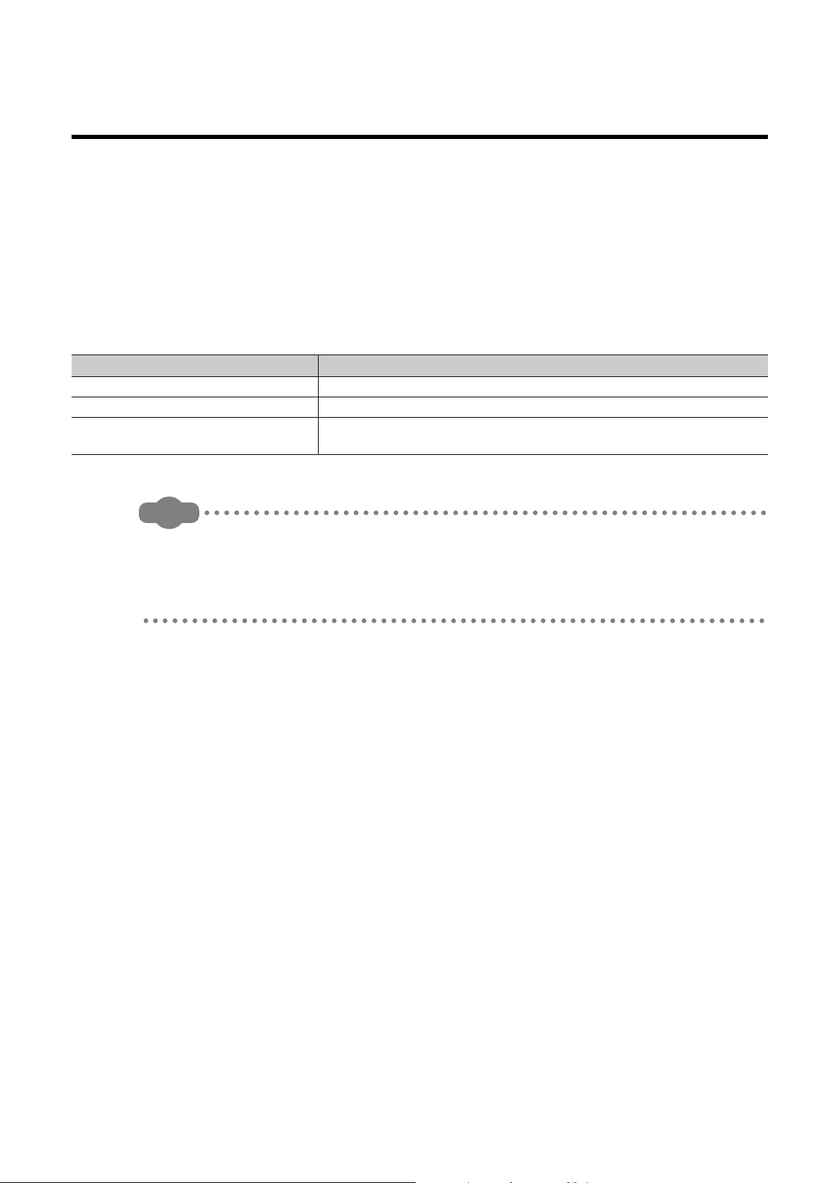
Relevant CPU modules
CPU module Typ e name
High-speed Universal model QCPU Q03UDVCPU, Q04UDVCPU, Q06UDVCPU, Q13UDVCPU, Q26UDVCPU
Universal model Process CPU Q04UDPVCPU, Q06UDPVCPU, Q13UDPVCPU, Q26UDPVCPU
LCPU
L02CPU, L02CPU-P, L06CPU, L06CPU-P, L26CPU, L26CPU-P,
L26CPU-BT, L26CPU-PBT
● This manual does not describe the details of the error codes, special relay (SM), and special register (SD).
For details, refer to the user's manual for the CPU module used.
QCPU User's Manual (Hardware Design, Maintenance and Inspection)
MELSEC-L CPU Module User's Manual (Hardware Design, Maintenance and Inspection)
● The L02SCPU and L02SCPU-P do not support the data logging function.
9
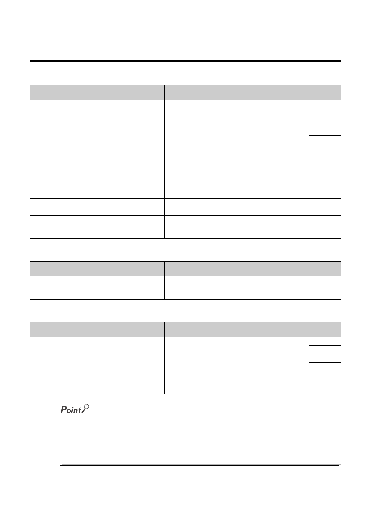
RELEVANT MANUALS
(1) CPU module user's manual
Manual name
[manual number (model code)]
QCPU User's Manual (Hardware Design, Maintenance and
Inspection)
[SH-080483ENG, 13JR73]
MELSEC-L CPU Module User's Manual (Hardware Design,
Maintenance and Inspection)
[SH-080890ENG, 13JZ36]
QnUCPU User's Manual (Function Explanation, Program
Fundamentals)
[SH-080807ENG, 13JZ27]
MELSEC-L CPU Module User's Manual (Function Explanation,
Program Fundamentals)
[SH-080889ENG, 13JZ35]
QnUCPU User's Manual (Communication via Built-in Ethernet Port)
[SH-080811ENG, 13JZ29]
MELSEC-L CPU Module User's Manual (Built-In Ethernet
Function)
[SH-080891ENG, 13JZ37]
Description
Specifications of the CPU modules, power supply modules, base units,
extension cables, memory cards, SD memory cards, extended SRAM
cassettes, and batteries, information on how to establish a system,
maintenance and inspection, and troubleshooting
Specifications of the CPU modules, power supply modules, display unit,
branch module, extension module, SD memory cards, and batteries,
information on how to establish a system, maintenance and inspection,
and troubleshooting
Functions and devices of the CPU module, and programming
Functions and devices of the CPU module, and programming
Detailed description of the Ethernet function of the CPU module
Detailed description of the Ethernet function of the CPU module
Available
form
Print book
PDF
Print book
e-Manual
PDF
Print book
PDF
Print book
e-Manual
PDF
Print book
PDF
Print book
e-Manual
PDF
(2) Programming manual
Manual name
[manual number (model code)]
MELSEC-Q/L Programming Manual (Common Instruction)
[SH-080809ENG, 13JW10]
(3) Operating manual
Manual name
[manual number (model code)]
GX Works2 Version 1 Operating Manual (Common)
[SH-080779ENG, 13JU63]
GX Developer Version 8 Operating Manual
[SH-080373E, 13JU41]
GX LogViewer Version 1 Operating Manual
[SH-080915ENG, 13JU68]
e-Manual refers to the Mitsubishi Electric FA electronic book manuals that can be browsed using a dedicated tool. e-Manual
has the following features:
• Required information can be cross-searched in multiple manuals.
• Other manuals can be accessed from the links in the manual.
• The hardware specifications of each part can be found from the product figures.
• Pages that users often browse can be bookmarked.
• Sample programs can be copied to an engineering tool.
Description
Detailed description and usage of instructions used in programs
Description
System configuration, parameter settings, and online operations
(common to Simple project and Structured project) of GX Works2
Operating methods of GX Developer, such as programming, printing,
monitoring, and debugging
System configuration, functions, and operating methods of GX
LogViewer
Available
form
Print book
e-Manual
PDF
Available
form
Print book
PDF
Print book
PDF
Print book
e-Manual
PDF
10

Memo
11

CONTENTS
CONTENTS
SAFETY PRECAUTIONS . . . . . . . . . . . . . . . . . . . . . . . . . . . . . . . . . . . . . . . . . . . . . . . . . . . . . . . . . . . . . 1
CONDITIONS OF USE FOR THE PRODUCT . . . . . . . . . . . . . . . . . . . . . . . . . . . . . . . . . . . . . . . . . . . . . 8
INTRODUCTION . . . . . . . . . . . . . . . . . . . . . . . . . . . . . . . . . . . . . . . . . . . . . . . . . . . . . . . . . . . . . . . . . . . . 9
RELEVANT MANUALS . . . . . . . . . . . . . . . . . . . . . . . . . . . . . . . . . . . . . . . . . . . . . . . . . . . . . . . . . . . . . . 10
MANUAL PAGE ORGANIZATION. . . . . . . . . . . . . . . . . . . . . . . . . . . . . . . . . . . . . . . . . . . . . . . . . . . . . . 16
TERMS . . . . . . . . . . . . . . . . . . . . . . . . . . . . . . . . . . . . . . . . . . . . . . . . . . . . . . . . . . . . . . . . . . . . . . . . . . 19
CHAPTER 1 DATA LOGGING 20
1.1 Features . . . . . . . . . . . . . . . . . . . . . . . . . . . . . . . . . . . . . . . . . . . . . . . . . . . . . . . . . . . . . . . . . . 20
1.2 Processing Outline . . . . . . . . . . . . . . . . . . . . . . . . . . . . . . . . . . . . . . . . . . . . . . . . . . . . . . . . . . 25
CHAPTER 2 SYSTEM CONFIGURATION 26
2.1 Overall System Configuration. . . . . . . . . . . . . . . . . . . . . . . . . . . . . . . . . . . . . . . . . . . . . . . . . . 26
2.1.1 Software. . . . . . . . . . . . . . . . . . . . . . . . . . . . . . . . . . . . . . . . . . . . . . . . . . . . . . . . . . . . . . . . . .27
2.1.2 Connection from a USB or serial port . . . . . . . . . . . . . . . . . . . . . . . . . . . . . . . . . . . . . . . . . . .28
2.1.3 Connection from an interface board . . . . . . . . . . . . . . . . . . . . . . . . . . . . . . . . . . . . . . . . . . . . .31
2.2 Precautions for Ethernet Connection . . . . . . . . . . . . . . . . . . . . . . . . . . . . . . . . . . . . . . . . . . . . 32
2.3 Operating Environment for the Configuration Tool . . . . . . . . . . . . . . . . . . . . . . . . . . . . . . . . . . 33
CHAPTER 3 SPECIFICATIONS 34
3.1 Function Specifications. . . . . . . . . . . . . . . . . . . . . . . . . . . . . . . . . . . . . . . . . . . . . . . . . . . . . . . 34
3.2 Folder Structure . . . . . . . . . . . . . . . . . . . . . . . . . . . . . . . . . . . . . . . . . . . . . . . . . . . . . . . . . . . . 36
3.3 CSV File Output Format . . . . . . . . . . . . . . . . . . . . . . . . . . . . . . . . . . . . . . . . . . . . . . . . . . . . . . 37
3.3.1 CSV format specifications . . . . . . . . . . . . . . . . . . . . . . . . . . . . . . . . . . . . . . . . . . . . . . . . . . . . 37
3.3.2 Output details of lines and columns . . . . . . . . . . . . . . . . . . . . . . . . . . . . . . . . . . . . . . . . . . . . .37
3.3.3 Value ranges by output format . . . . . . . . . . . . . . . . . . . . . . . . . . . . . . . . . . . . . . . . . . . . . . . . .42
3.4 Size of Data Logging Setting File . . . . . . . . . . . . . . . . . . . . . . . . . . . . . . . . . . . . . . . . . . . . . . .43
CHAPTER 4 PROCEDURES AND SETTINGS BEFORE SYSTEM OPERATION 44
CHAPTER 5 START-UP OF THE CONFIGURATION TOOL 46
5.1 Getting the Configuration Tool . . . . . . . . . . . . . . . . . . . . . . . . . . . . . . . . . . . . . . . . . . . . . . . . . 46
5.2 Installing/Uninstalling the Configuration Tool . . . . . . . . . . . . . . . . . . . . . . . . . . . . . . . . . . . . . . 47
5.3 Starting the Configuration Tool . . . . . . . . . . . . . . . . . . . . . . . . . . . . . . . . . . . . . . . . . . . . . . . . . 47
5.4 Switching a Display Language . . . . . . . . . . . . . . . . . . . . . . . . . . . . . . . . . . . . . . . . . . . . . . . . .47
CHAPTER 6 DATA LOGGING FUNCTION 48
12
6.1 Target Data. . . . . . . . . . . . . . . . . . . . . . . . . . . . . . . . . . . . . . . . . . . . . . . . . . . . . . . . . . . . . . . . 49
6.2 Sampling of Target Data . . . . . . . . . . . . . . . . . . . . . . . . . . . . . . . . . . . . . . . . . . . . . . . . . . . . . . 50
6.3 Logging Type . . . . . . . . . . . . . . . . . . . . . . . . . . . . . . . . . . . . . . . . . . . . . . . . . . . . . . . . . . . . . . 56
6.3.1 Continuous logging . . . . . . . . . . . . . . . . . . . . . . . . . . . . . . . . . . . . . . . . . . . . . . . . . . . . . . . . .56
6.3.2 Trigger logging . . . . . . . . . . . . . . . . . . . . . . . . . . . . . . . . . . . . . . . . . . . . . . . . . . . . . . . . . . . . .57
6.3.3 Specification period logging . . . . . . . . . . . . . . . . . . . . . . . . . . . . . . . . . . . . . . . . . . . . . . . . . . .61

6.4 Data Logging Status . . . . . . . . . . . . . . . . . . . . . . . . . . . . . . . . . . . . . . . . . . . . . . . . . . . . . . . . . 63
6.5 Data Logging File . . . . . . . . . . . . . . . . . . . . . . . . . . . . . . . . . . . . . . . . . . . . . . . . . . . . . . . . . . . 64
6.5.1 Saving format of the data logging file. . . . . . . . . . . . . . . . . . . . . . . . . . . . . . . . . . . . . . . . . . . .64
6.5.2 How sampled data are saved. . . . . . . . . . . . . . . . . . . . . . . . . . . . . . . . . . . . . . . . . . . . . . . . . .64
6.5.3 File switching setting . . . . . . . . . . . . . . . . . . . . . . . . . . . . . . . . . . . . . . . . . . . . . . . . . . . . . . . .65
6.6 Buffer Capacity . . . . . . . . . . . . . . . . . . . . . . . . . . . . . . . . . . . . . . . . . . . . . . . . . . . . . . . . . . . . . 68
6.7 Data Missing. . . . . . . . . . . . . . . . . . . . . . . . . . . . . . . . . . . . . . . . . . . . . . . . . . . . . . . . . . . . . . . 69
6.8 SD Memory Card Life When the Data Logging Function is Used. . . . . . . . . . . . . . . . . . . . . . . 71
6.9 Precautions to Take When Using the Data Logging Function . . . . . . . . . . . . . . . . . . . . . . . . . 73
CHAPTER 7 OTHER FUNCTIONS 77
7.1 Data Logging Operation at Transition to RUN . . . . . . . . . . . . . . . . . . . . . . . . . . . . . . . . . . . . . 77
7.2 Auto Logging by Inserting an SD Memory Card . . . . . . . . . . . . . . . . . . . . . . . . . . . . . . . . . . . . 78
7.3 File Access . . . . . . . . . . . . . . . . . . . . . . . . . . . . . . . . . . . . . . . . . . . . . . . . . . . . . . . . . . . . . . . . 81
7.4 Data Logging File Transfer Function. . . . . . . . . . . . . . . . . . . . . . . . . . . . . . . . . . . . . . . . . . . . . 82
7.4.1 Procedure overview of the data logging file transfer function . . . . . . . . . . . . . . . . . . . . . . . . .83
7.4.2 Directory structure of the FTP server . . . . . . . . . . . . . . . . . . . . . . . . . . . . . . . . . . . . . . . . . . . .84
7.4.3 File transfer status . . . . . . . . . . . . . . . . . . . . . . . . . . . . . . . . . . . . . . . . . . . . . . . . . . . . . . . . . .85
7.4.4 File transfer test . . . . . . . . . . . . . . . . . . . . . . . . . . . . . . . . . . . . . . . . . . . . . . . . . . . . . . . . . . . .88
7.4.5 File transfer diagnostics . . . . . . . . . . . . . . . . . . . . . . . . . . . . . . . . . . . . . . . . . . . . . . . . . . . . . .89
7.4.6 Precautions for using the data logging file transfer function . . . . . . . . . . . . . . . . . . . . . . . . . .90
7.4.7 Stack logging file transfer. . . . . . . . . . . . . . . . . . . . . . . . . . . . . . . . . . . . . . . . . . . . . . . . . . . . .92
7.4.8 Transfer completing/Non-completing file distinction indication. . . . . . . . . . . . . . . . . . . . . . . . .94
CHAPTER 8 HOW TO USE THE CONFIGURATION TOOL 95
8.1 Setting Flow Chart . . . . . . . . . . . . . . . . . . . . . . . . . . . . . . . . . . . . . . . . . . . . . . . . . . . . . . . . . . 95
8.2 Window Structure . . . . . . . . . . . . . . . . . . . . . . . . . . . . . . . . . . . . . . . . . . . . . . . . . . . . . . . . . . . 96
8.2.1 Main window . . . . . . . . . . . . . . . . . . . . . . . . . . . . . . . . . . . . . . . . . . . . . . . . . . . . . . . . . . . . . .96
8.2.2 Menu structure . . . . . . . . . . . . . . . . . . . . . . . . . . . . . . . . . . . . . . . . . . . . . . . . . . . . . . . . . . . . .97
8.2.3 Toolbar structure . . . . . . . . . . . . . . . . . . . . . . . . . . . . . . . . . . . . . . . . . . . . . . . . . . . . . . . . . . .98
8.2.4 Edit item tree . . . . . . . . . . . . . . . . . . . . . . . . . . . . . . . . . . . . . . . . . . . . . . . . . . . . . . . . . . . . . .99
8.2.5 Status bar. . . . . . . . . . . . . . . . . . . . . . . . . . . . . . . . . . . . . . . . . . . . . . . . . . . . . . . . . . . . . . . .100
8.2.6 Common operations. . . . . . . . . . . . . . . . . . . . . . . . . . . . . . . . . . . . . . . . . . . . . . . . . . . . . . . .101
8.2.7 Device batch replacement . . . . . . . . . . . . . . . . . . . . . . . . . . . . . . . . . . . . . . . . . . . . . . . . . . .102
8.3 Project Management. . . . . . . . . . . . . . . . . . . . . . . . . . . . . . . . . . . . . . . . . . . . . . . . . . . . . . . . 103
8.3.1 Creating a new project . . . . . . . . . . . . . . . . . . . . . . . . . . . . . . . . . . . . . . . . . . . . . . . . . . . . . .103
8.3.2 Opening a project . . . . . . . . . . . . . . . . . . . . . . . . . . . . . . . . . . . . . . . . . . . . . . . . . . . . . . . . . .103
8.3.3 Saving a project . . . . . . . . . . . . . . . . . . . . . . . . . . . . . . . . . . . . . . . . . . . . . . . . . . . . . . . . . . .104
8.3.4 Changing a programmable controller series . . . . . . . . . . . . . . . . . . . . . . . . . . . . . . . . . . . . .105
8.3.5 Reading the data logging setting from the SD memory card . . . . . . . . . . . . . . . . . . . . . . . . .106
8.3.6 Writing the data logging setting to the SD memory card . . . . . . . . . . . . . . . . . . . . . . . . . . . .108
8.4 Data Logging Setting . . . . . . . . . . . . . . . . . . . . . . . . . . . . . . . . . . . . . . . . . . . . . . . . . . . . . . . 110
8.4.1 Data logging setting list . . . . . . . . . . . . . . . . . . . . . . . . . . . . . . . . . . . . . . . . . . . . . . . . . . . . .110
8.4.2 Change of the data logging setting window . . . . . . . . . . . . . . . . . . . . . . . . . . . . . . . . . . . . . .112
8.4.3 Logging type. . . . . . . . . . . . . . . . . . . . . . . . . . . . . . . . . . . . . . . . . . . . . . . . . . . . . . . . . . . . . .114
13

8.4.4 Sampling . . . . . . . . . . . . . . . . . . . . . . . . . . . . . . . . . . . . . . . . . . . . . . . . . . . . . . . . . . . . . . . .115
8.4.5 Data . . . . . . . . . . . . . . . . . . . . . . . . . . . . . . . . . . . . . . . . . . . . . . . . . . . . . . . . . . . . . . . . . . . . 117
8.4.6 Paste/Insert device copied in other application software . . . . . . . . . . . . . . . . . . . . . . . . . . . . 119
8.4.7 Batch data insertion . . . . . . . . . . . . . . . . . . . . . . . . . . . . . . . . . . . . . . . . . . . . . . . . . . . . . . . .120
8.4.8 Trigger . . . . . . . . . . . . . . . . . . . . . . . . . . . . . . . . . . . . . . . . . . . . . . . . . . . . . . . . . . . . . . . . . .121
8.4.9 Specification period . . . . . . . . . . . . . . . . . . . . . . . . . . . . . . . . . . . . . . . . . . . . . . . . . . . . . . . .123
8.4.10 Number of logging lines . . . . . . . . . . . . . . . . . . . . . . . . . . . . . . . . . . . . . . . . . . . . . . . . . . . . .124
8.4.11 CSV output. . . . . . . . . . . . . . . . . . . . . . . . . . . . . . . . . . . . . . . . . . . . . . . . . . . . . . . . . . . . . . .125
8.4.12 Save . . . . . . . . . . . . . . . . . . . . . . . . . . . . . . . . . . . . . . . . . . . . . . . . . . . . . . . . . . . . . . . . . . . .127
8.4.13 File transfer . . . . . . . . . . . . . . . . . . . . . . . . . . . . . . . . . . . . . . . . . . . . . . . . . . . . . . . . . . . . . .129
8.4.14 Movement . . . . . . . . . . . . . . . . . . . . . . . . . . . . . . . . . . . . . . . . . . . . . . . . . . . . . . . . . . . . . . .131
8.4.15 Finish . . . . . . . . . . . . . . . . . . . . . . . . . . . . . . . . . . . . . . . . . . . . . . . . . . . . . . . . . . . . . . . . . . .132
8.5 Common Setting. . . . . . . . . . . . . . . . . . . . . . . . . . . . . . . . . . . . . . . . . . . . . . . . . . . . . . . . . . . 133
8.5.1 Auto logging setting . . . . . . . . . . . . . . . . . . . . . . . . . . . . . . . . . . . . . . . . . . . . . . . . . . . . . . . .134
8.5.2 Buffer capacity setting . . . . . . . . . . . . . . . . . . . . . . . . . . . . . . . . . . . . . . . . . . . . . . . . . . . . . .135
8.6 Transfer Setup . . . . . . . . . . . . . . . . . . . . . . . . . . . . . . . . . . . . . . . . . . . . . . . . . . . . . . . . . . . . 136
8.6.1 Connection with a USB or Ethernet cable . . . . . . . . . . . . . . . . . . . . . . . . . . . . . . . . . . . . . . .136
8.6.2 Connection via a network. . . . . . . . . . . . . . . . . . . . . . . . . . . . . . . . . . . . . . . . . . . . . . . . . . . .138
8.6.3 Connection test . . . . . . . . . . . . . . . . . . . . . . . . . . . . . . . . . . . . . . . . . . . . . . . . . . . . . . . . . . . 140
8.6.4 Connection channel list . . . . . . . . . . . . . . . . . . . . . . . . . . . . . . . . . . . . . . . . . . . . . . . . . . . . .140
8.6.5 Searching CPU modules on the network . . . . . . . . . . . . . . . . . . . . . . . . . . . . . . . . . . . . . . . .141
8.7 Reading the Data Logging Setting from the CPU Module . . . . . . . . . . . . . . . . . . . . . . . . . . . 143
8.8 Writing the Data Logging Setting to the CPU Module. . . . . . . . . . . . . . . . . . . . . . . . . . . . . . . 145
8.9 Deleting the Data Logging Setting in the CPU Module. . . . . . . . . . . . . . . . . . . . . . . . . . . . . . 147
8.10 Logging Status and Operation . . . . . . . . . . . . . . . . . . . . . . . . . . . . . . . . . . . . . . . . . . . . . . . . 149
8.11 Logging File Operation . . . . . . . . . . . . . . . . . . . . . . . . . . . . . . . . . . . . . . . . . . . . . . . . . . . . . . 152
8.12 Data Logging File Transfer Status . . . . . . . . . . . . . . . . . . . . . . . . . . . . . . . . . . . . . . . . . . . . . 154
8.13 Checking the Product Information . . . . . . . . . . . . . . . . . . . . . . . . . . . . . . . . . . . . . . . . . . . . . 156
8.13.1 Opening the user's manual . . . . . . . . . . . . . . . . . . . . . . . . . . . . . . . . . . . . . . . . . . . . . . . . . .156
8.13.2 Checking the version information. . . . . . . . . . . . . . . . . . . . . . . . . . . . . . . . . . . . . . . . . . . . . .156
8.14 Available Characters. . . . . . . . . . . . . . . . . . . . . . . . . . . . . . . . . . . . . . . . . . . . . . . . . . . . . . . . 157
8.14.1 Available ASCII characters. . . . . . . . . . . . . . . . . . . . . . . . . . . . . . . . . . . . . . . . . . . . . . . . . . .157
8.14.2 Characters available for file and folder (directory) names . . . . . . . . . . . . . . . . . . . . . . . . . . .158
8.14.3 Characters available for the data logging setting . . . . . . . . . . . . . . . . . . . . . . . . . . . . . . . . . .158
CHAPTER 9 SD MEMORY CARD 159
9.1 Precautions for Using SD Memory Cards. . . . . . . . . . . . . . . . . . . . . . . . . . . . . . . . . . . . . . . . 159
CHAPTER 10 PROCESSING TIME 161
10.1 Data Logging Processing Time. . . . . . . . . . . . . . . . . . . . . . . . . . . . . . . . . . . . . . . . . . . . . . . . 161
10.1.1 Continuous logging, specification period logging . . . . . . . . . . . . . . . . . . . . . . . . . . . . . . . . . .162
10.1.2 Trigger logging . . . . . . . . . . . . . . . . . . . . . . . . . . . . . . . . . . . . . . . . . . . . . . . . . . . . . . . . . . . .165
10.2 Checking the Processing Time . . . . . . . . . . . . . . . . . . . . . . . . . . . . . . . . . . . . . . . . . . . . . . . . 167
10.2.1 Checking the data logging processing time . . . . . . . . . . . . . . . . . . . . . . . . . . . . . . . . . . . . . .167
10.3 Impact on Scan Time . . . . . . . . . . . . . . . . . . . . . . . . . . . . . . . . . . . . . . . . . . . . . . . . . . . . . . . 168
14

10.4 Processing Time of Each Instruction . . . . . . . . . . . . . . . . . . . . . . . . . . . . . . . . . . . . . . . . . . . 169
CHAPTER 11 DATA LOGGING INSTRUCTIONS 170
11.1 Trigger Logging Set (Reset) (LOGTRG(R)) . . . . . . . . . . . . . . . . . . . . . . . . . . . . . . . . . . . . . . 171
11.2 Data Logging Name Read (SP.LOGNAMER). . . . . . . . . . . . . . . . . . . . . . . . . . . . . . . . . . . . . 173
11.3 Data Logging File Name Addition (SP.LOGFILES) . . . . . . . . . . . . . . . . . . . . . . . . . . . . . . . . . 175
CHAPTER 12 SPECIAL RELAY AND SPECIAL REGISTER 178
12.1 Special Relay List . . . . . . . . . . . . . . . . . . . . . . . . . . . . . . . . . . . . . . . . . . . . . . . . . . . . . . . . . . 178
12.2 Special Register List. . . . . . . . . . . . . . . . . . . . . . . . . . . . . . . . . . . . . . . . . . . . . . . . . . . . . . . . 179
CHAPTER 13 TROUBLESHOOTING 180
13.1 List of the Errors That May Occur in Data Logging. . . . . . . . . . . . . . . . . . . . . . . . . . . . . . . . . 180
13.2 Troubleshooting by Symptom . . . . . . . . . . . . . . . . . . . . . . . . . . . . . . . . . . . . . . . . . . . . . . . . . 183
13.2.1 Troubleshooting on CSV file output . . . . . . . . . . . . . . . . . . . . . . . . . . . . . . . . . . . . . . . . . . . .183
13.2.2 Troubleshooting on SD memory cards . . . . . . . . . . . . . . . . . . . . . . . . . . . . . . . . . . . . . . . . . .183
13.2.3 Troubleshooting on the configuration tool . . . . . . . . . . . . . . . . . . . . . . . . . . . . . . . . . . . . . . .183
13.2.4 Troubleshooting on the entire system during operation of the data logging function. . . . . . .184
13.2.5 Troubleshooting on the data logging status . . . . . . . . . . . . . . . . . . . . . . . . . . . . . . . . . . . . . .185
13.2.6 Troubleshooting on the data logging file transfer function . . . . . . . . . . . . . . . . . . . . . . . . . . .185
APPENDICES 187
Appendix 1 Installing a USB Driver . . . . . . . . . . . . . . . . . . . . . . . . . . . . . . . . . . . . . . . . . . . . . . . . . 187
Appendix 2 Added and Changed Functions. . . . . . . . . . . . . . . . . . . . . . . . . . . . . . . . . . . . . . . . . . . 190
INDEX 192
INSTRUCTION INDEX 194
REVISIONS . . . . . . . . . . . . . . . . . . . . . . . . . . . . . . . . . . . . . . . . . . . . . . . . . . . . . . . . . . . . . . . . . . . . . . 196
WARRANTY . . . . . . . . . . . . . . . . . . . . . . . . . . . . . . . . . . . . . . . . . . . . . . . . . . . . . . . . . . . . . . . . . . . . . 199
TRADEMARKS . . . . . . . . . . . . . . . . . . . . . . . . . . . . . . . . . . . . . . . . . . . . . . . . . . . . . . . . . . . . . . . . . . . 200
15
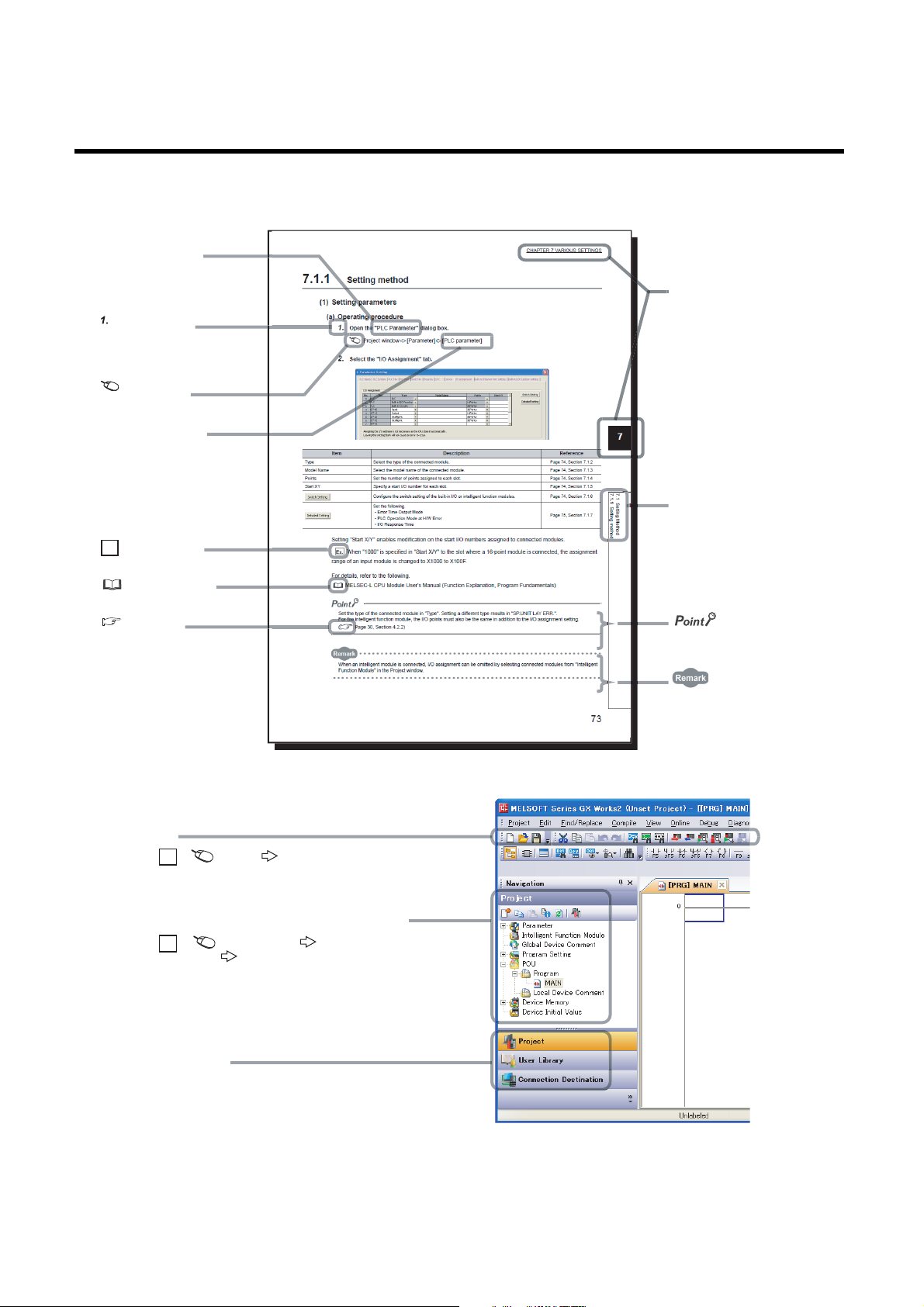
MANUAL PAGE ORGANIZATION
The section of
the current page is shown.
The chapter of
the current page is shown.
"" is used for
screen names and items.
[ ] is used for items
in the menu bar and
the project window.
shows operating
procedures.
shows reference
manuals.
shows notes that
requires attention.
shows mouse
operations.
*1
shows
reference pages.
shows setting or
operating examples.
Ex.
shows useful
information.
A window selected in the view selection area is displayed.
View selection area
[Online] [Write to PLC...]
Select [Online] on the menu bar,
and then select [Write to PLC...].
Project window
[Parameter]
[PLC Parameter]
Select [Project] from the view selection
area to open the Project window.
Menu bar
Ex.
Ex.
In the Project window, expand [Parameter] and
select [PLC Parameter].
In this manual, pages are organized and the symbols are used as shown below.
The following illustration is for explanation purpose only, and should not be referred to as an actual documentation.
*1 The mouse operation example (for GX Works2) is provided below.
16
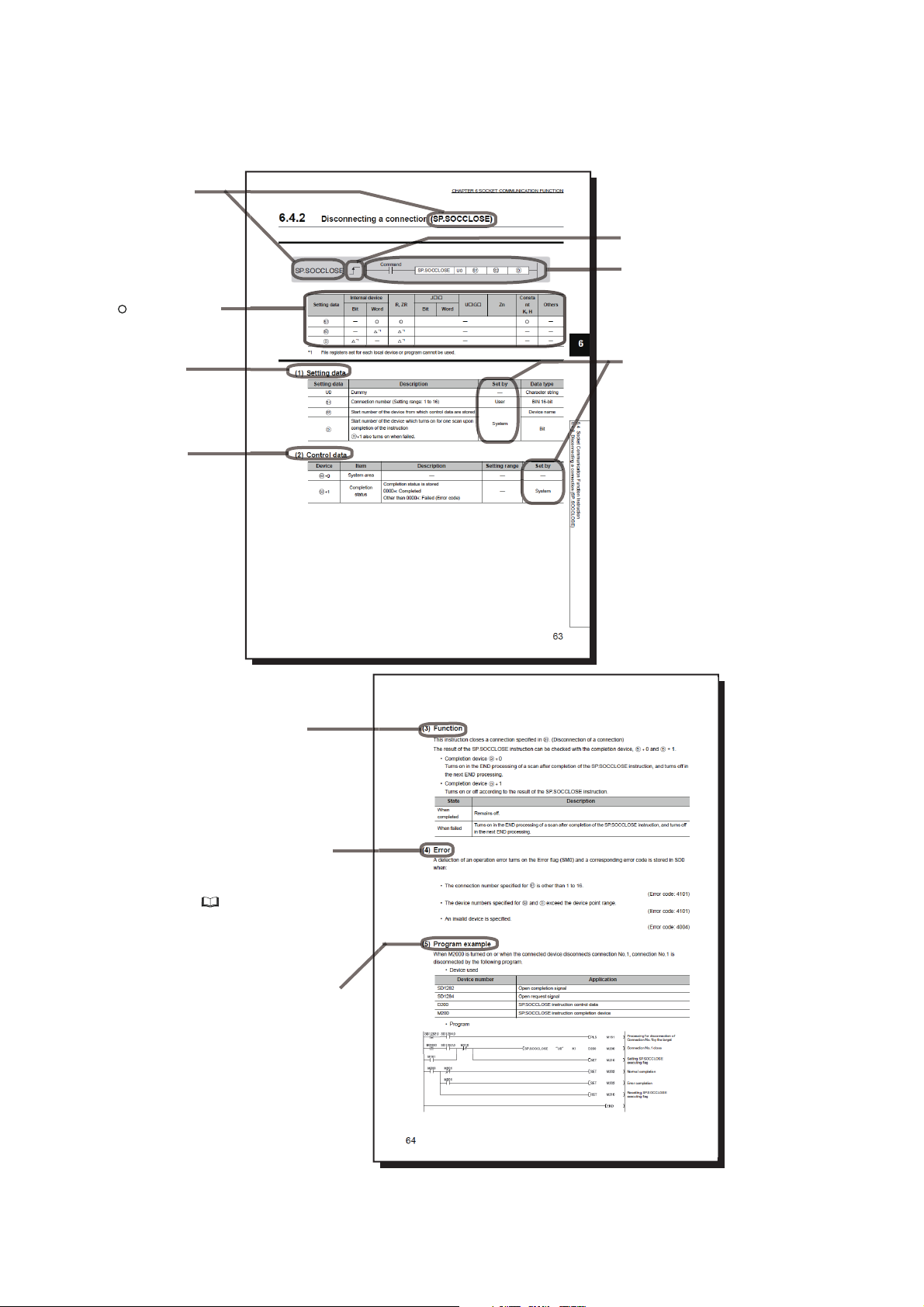
Pages describing instructions are organized as shown below.
Descriptions of
setting data and data type
Instruction name
Structure of the instruction
in the ladder mode
shows the devices
applicable to the instruction
Descriptions of
control data (if any)
Execution condition of the instruction
Setting side
User
: Device value is set by the user.
System: Device value is set by
the CPU module.
Conditions for the error and
error codes
For the errors not described in
this manual, refer to the following.
User's Manual (Hardware
Design, Maintenance and Inspection)
for the CPU module used
Simple program example(s)
and descriptions of the devices used
Detailed descriptions
of the instruction
The following illustration is for explanation purpose only, and should not be referred to as an actual documentation.
17
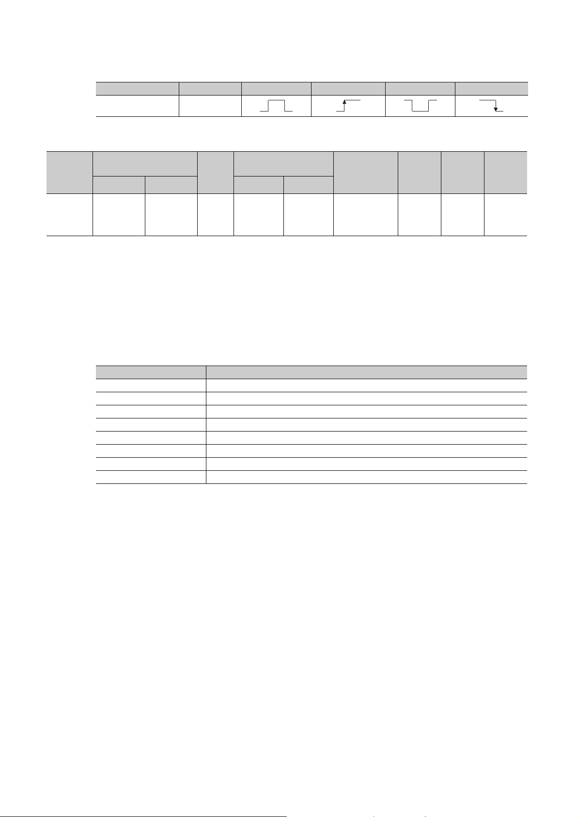
Setting
data
Applicable
*1
device
• Instructions can be executed under the following conditions.
Execution condition Any time During on On the rising edge During off On the falling edge
Symbol No symbol
• The following devices can be used.
Internal device
(system, user)
Bit Word Bit Word
X, Y, M, L,
SM, F, B, SB,
FX, FY
*2
T, ST, C,
D, W, SD, SW
*2
, @
FD
File
register
*3
R, ZR
Link direct device
J\
J\X,
J\Y,
J\B,
J\SB
*4
J\W,
J\SW
*1 For details on each device, refer to the following.
User's Manual (Function Explanation, Program Fundamentals) for the CPU module used
*2 FX and FY can be used for bit data only, and FD for word data only.
*3 When T, ST, and C are used in an instruction other than the following, they are used as word devices.
Instructions that T, ST, and C are used as bit devices: LD, LDI, AND, ANI, OR, ORI, LDP, LDF, ANDP, ANDF, ORP, ORF,
OUT, and RST
*4 These devices can be used in the CC-Link IE Field Network, CC-Link IE Controller Network, MELSECNET/H, and
MELSECNET/10.
*5 In the "Constant" and "Others" columns, a device(s) that can be set for each instruction is shown.
Intelligent
function module
device
U\G
U\G Z K, H, E, $
Index
register
Zn
Constant*5Others
P, I, J, U,
DX, DY, N,
BL, TR,
BL\S, V
*5
• The following data types can be used.
Data type Description
Bit Bit data or the start number of bit data
BIN 16-bit 16-bit binary data or the start number of word device
BIN 32-bit 32-bit binary data or the start number of double-word device
BCD 4-digit Four-digit binary-coded decimal data
BCD 8-digit Eight-digit binary-coded decimal data
Real number Floating-point data
String Character string data
Device name Device name data
18
TERMS
Unless otherwise specified, this manual uses the following terms.
Ter m Description
Configuration tool Another term for the CPU Module Logging Configuration Tool
CPU module A generic term for the High-speed Universal model QCPU, Universal model Process CPU, and the LCPU
CPU Module Logging Configuration
To ol
Display unit A liquid crystal display to be attached to the LCPU
GX Developer
GX Works2
GX LogViewer Software to display data collected by data logging
LCPU
Programming tool A generic term for GX Works2 and GX Developer
Universal model Process CPU
QnUDPVCPU
High-speed Universal model QCPU
QnUDVCPU
SD memory card
Software to configure data logging settings and to manage collected data
The product name of the software package for the MELSEC programmable controllers
A generic term for the L02CPU, L02CPU-P, L06CPU, L06CPU-P, L26CPU, L26CPU-P, L26CPU-BT, and L26CPUPBT
A generic term for the Q04UDPVCPU, Q06UDPVCPU, Q13UDPVCPU, and Q26UDPVCPU
A generic term for the Q03UDVCPU, Q04UDVCPU, Q06UDVCPU, Q13UDVCPU, and Q26UDVCPU
Secure Digital Memory Card, which is a flash memory device. The NZ1MEM-2GBSD, NZ1MEM-4GBSD, NZ1MEM8GBSD, NZ1MEM-16GBSD, L1MEM-2GBSD, and L1MEM-4GBSD are available.
19
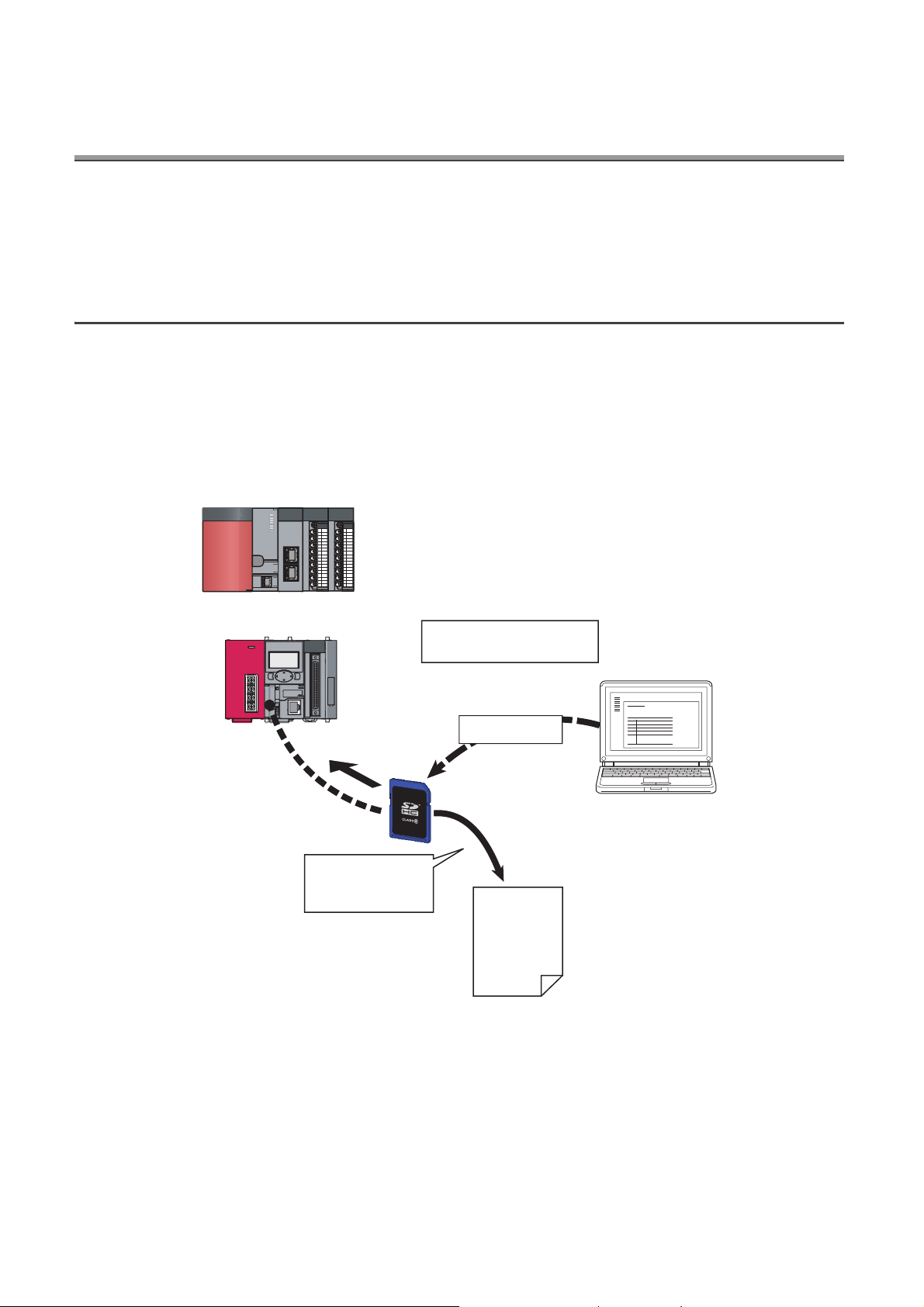
CHAPTER 1 DATA LOGGING
Device data can be sampled
with just a simple setting.
CSV format
Data can be stored
on an SD memory
card in CSV format.
Configurations
:
18:55:18 67,723,36,0
18:55:19 68,741,36,0
18:55:20 69,712,36,1
18:55:20 70,724,36,1
18:55:20 71,732,36,1
18:55:20 72,733,
18:55:16 65,725,36,1
18:55:17 66,756,36,0
QnUDVCPU
Configuration tool
LCPU
or
The data logging function of the CPU module stores collected device data on an SD memory card in CSV format, with
just a simple setting.
1.1 Features
The following explains the features of the data logging function.
(1) Logging of device data is easy.
No program needs to be created for logging. Device data can be logged by only setting parameters.
Logged data can be stored on an SD memory card in CSV format.
20
CHAPTER 1 DATA LOGGING
2008/1/10 14:25:34
2008/1/10 14:25:34
2008/1/10 14:25:34
2008/1/10 14:25:34
2008/1/10 14:25:34
2008/1/10 14:25:34
2008/1/10 14:25:34
2008/1/10 14:25:34
2008/1/10 14:25:34
2008/1/10 14:25:34
2008/1/10 14:25:34
2008/1/10 14:25:34
2008/1/10 14:25:34
2008/1/10 14:25:34
2008/1/10 14:25:34
2008/1/10 14:25:34
2008/1/10 14:25:34
2008/1/10 14:25:35
150
200
250
300
350
400
450
500
550
600
650
700
750
800
850
900
950
0
18
18
19
18
18
19
18
15
12
11
5
3
12
14
17
18
19
18
356
330
280
310
300
285
290
310
312
333
340
352
360
362
363
363
365
370
39
39
39
42
43
46
47
48
49
50
50
51
51
50
50
50
49
49
Data before trigger
Data after trigger
Trigger occurred
Range of the data stored in a file
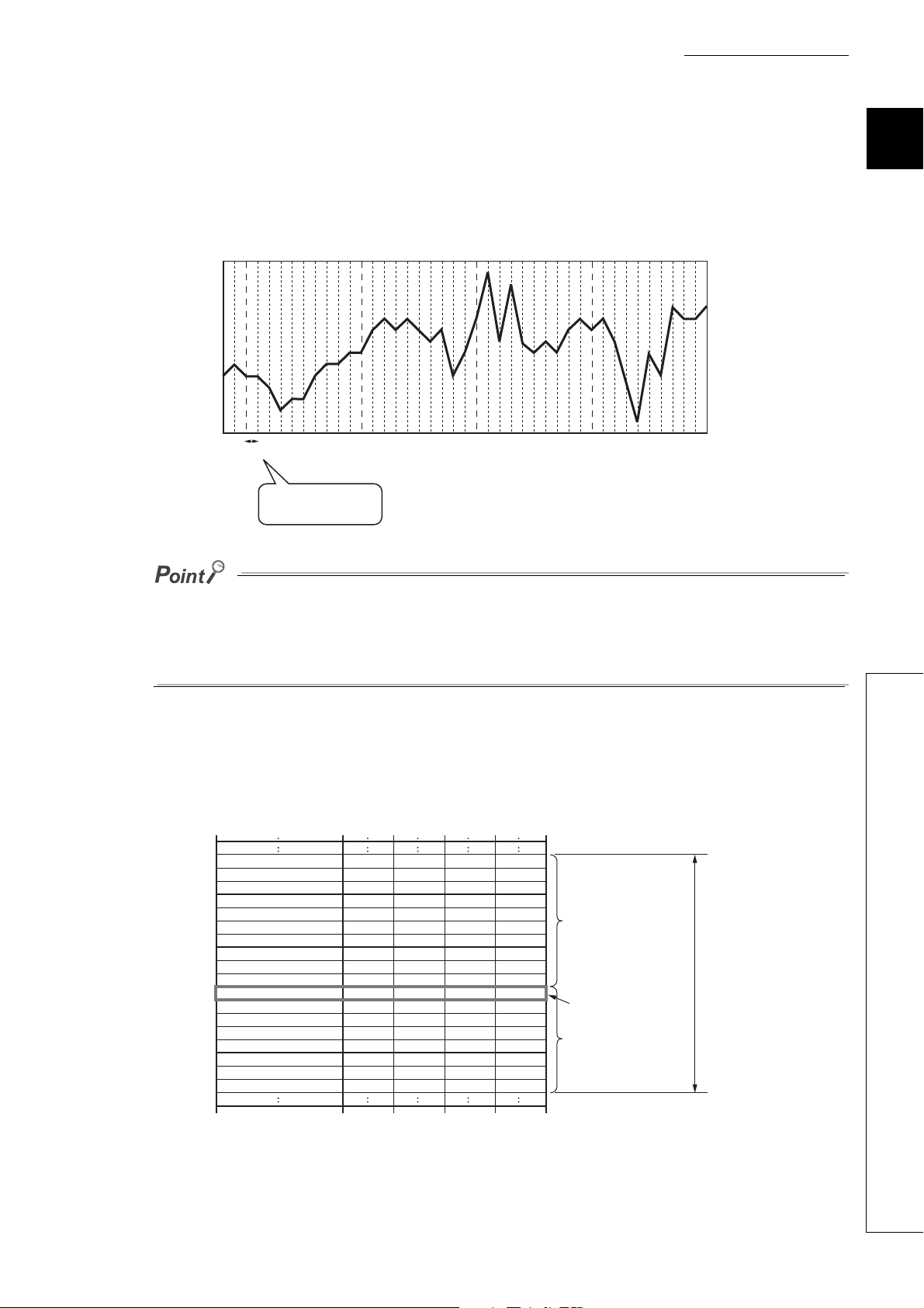
(2) Control data can be logged without missing a change (continuous logging).
Data logging is available every scan or on the millisecond time scale. Since changes in the specified control data
can be logged, the data logging function is effective to identify the cause of a problem. Also, logging is performed
at a high speed so that equipment can be analyzed with high accuracy.
When sampling data at intervals of 1ms
1ms
Slight changes in data
are caught.
1
Data logging is the best-effort type*1 function. Logging may not be performed at a specified sampling interval because
processing time may vary depending on the configuration or the other connected devices. After configuring the system,
thoroughly examine the processing time before starting the system operation. ( Page 161, CHAPTER 10)
*1 The concept of obtaining the maximum performance from the condition at the time.
(3) Problem analysis can be speeded up. (Trigger logging)
The states and changes in data can be stored as the data before and after a trigger. Since only the data before
and after occurrence of each problem can be stored, the cause of the problem can be identified quickly, and file
space can be saved.
1.1 Features
21
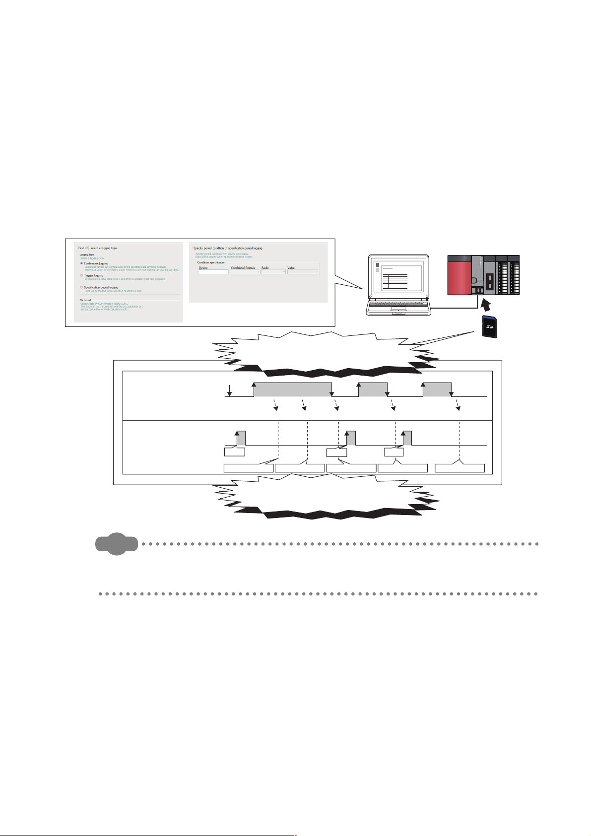
(4) Only the specific data can be collected in each file (specification period
Remark
ON ON
OFF OFF OFF
ON
ON ON ON
00000001.CSV 00000002.CSV 00000003.CSV 00000004.CSV 00000005.CSV
ABC_00000001.CSV ABC_00000002.CSV ABC_00000003.CSV DEF_00000004.CSV GHI_00000005.CSV
"ABC"
"DEF"
"GHI"
QnUDVCPU
<Operation of the
specification period logging>
Configuration tool
SD memory card
Logging start
Saved files
Period Ò Period Ó Period Ô
When the SP.LOGFILES instruction
is simultaneously used
Only the data logging results collected
under the specific conditions can be stored.
Any string can be added to saved file
names for each specified period.
Data collection period: M0
Data collection timing: Each
scanning cycle
logging).
Using the specification period logging (Page 61, Section 6.3.3), data can be collected only while the specific
conditions are met, and files can be saved for each specified period.
Capacity increase resulting from collecting unnecessary data can thus be prevented, and time taken to analyze
and organize data can also be shortened. Even when the conditions change, all data that meet the changed
conditions can be collected.
Furthermore, together with the data logging file name addition instruction (SP.LOGFILES) (Page 175,
Section 11.3), the specification period logging allows any character to be added to the data logging results for
each specified period, facilitating the control of data logging files.
The specification period logging is available only for the High-speed Universal model QCPU and the Universal model
Process CPU. Before using the specification period logging, check the versions of the CPU module and configuration tool
used. ( Page 190, Appendix 2)
22
CHAPTER 1 DATA LOGGING
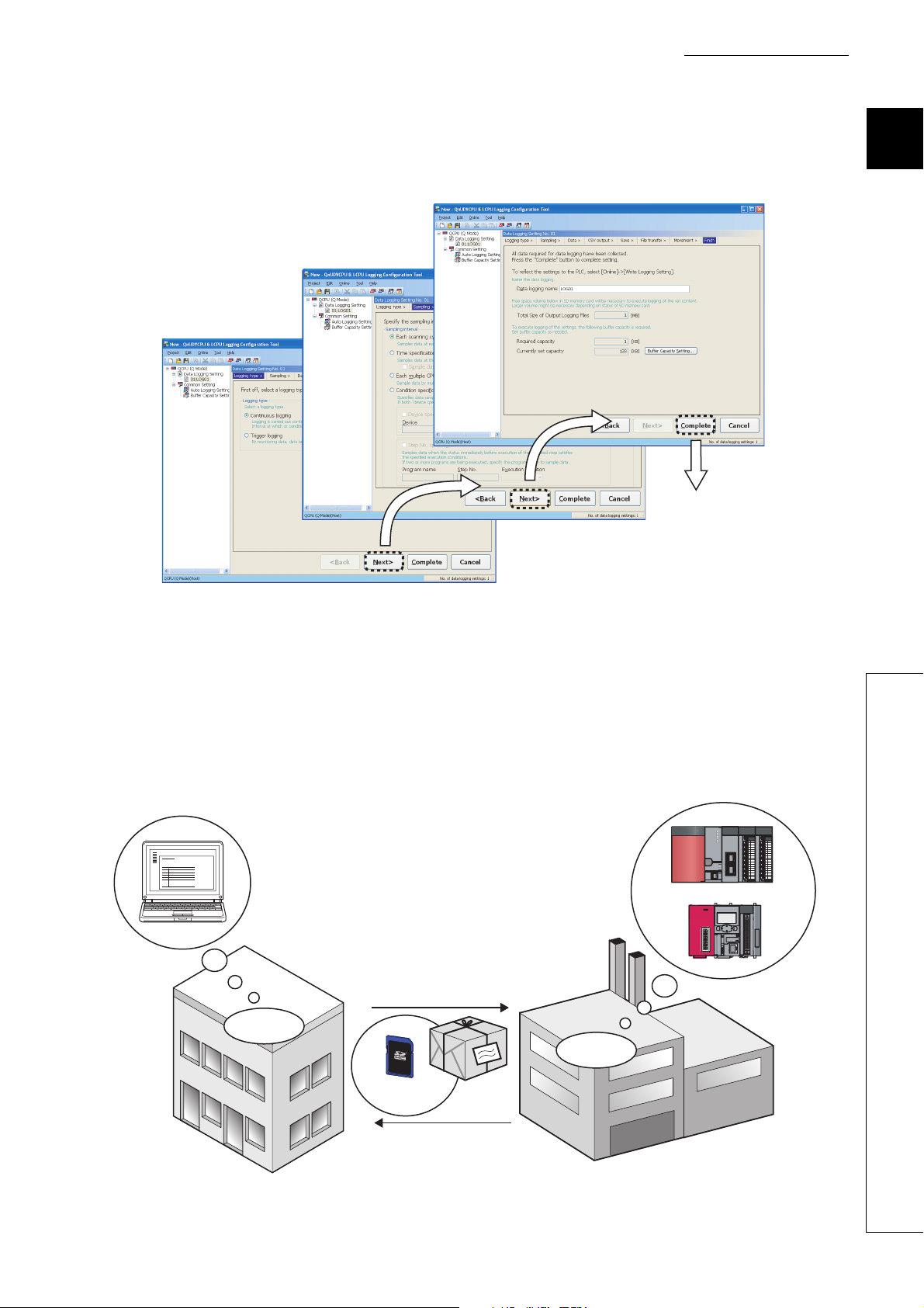
QnUDVCPU
SD memory
card
1) Sending a card
3) Returning the card
Office
Factory floor
2) Sampling
data
Logging starts automatically by
inserting the SD memory card into
the slot of the CPU module.
4) Analyzing
data
LCPU
or
(5) Configuration for logging is simple.
Logging settings can be configured easily by following the wizard.
1
Settings configured.
(6) A large volume of logging files can be stored.
Use of an SD memory card of up to 16GB enables a long-term logging.
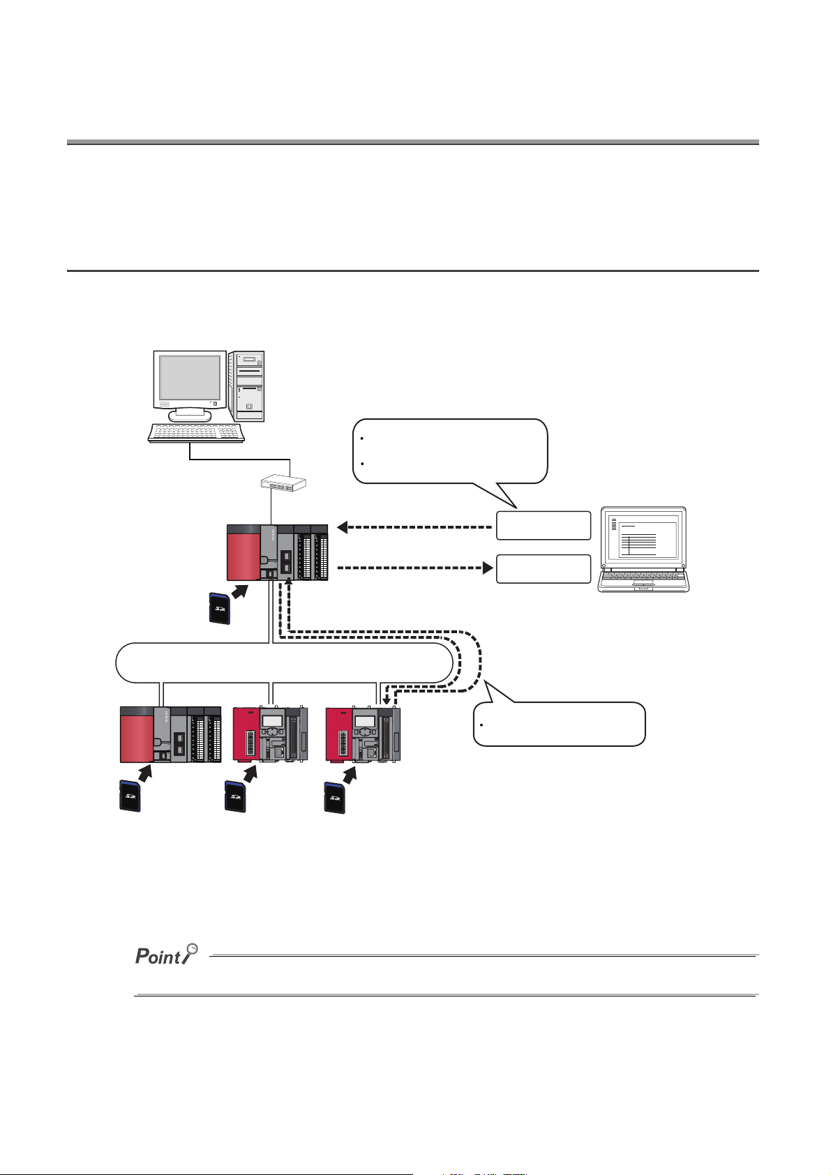
(7) Data sampling for troubleshooting can be instructed easily.
Data required for troubleshooting can be collected by simply sending an SD memory card (where auto logging
setting data are stored) to the factory floor and inserting it into the slot of the CPU module. (Auto logging function)
Furthermore, the logged data can be analyzed if the SD memory card is returned to the office after termination of
the logging.
1.1 Features
23
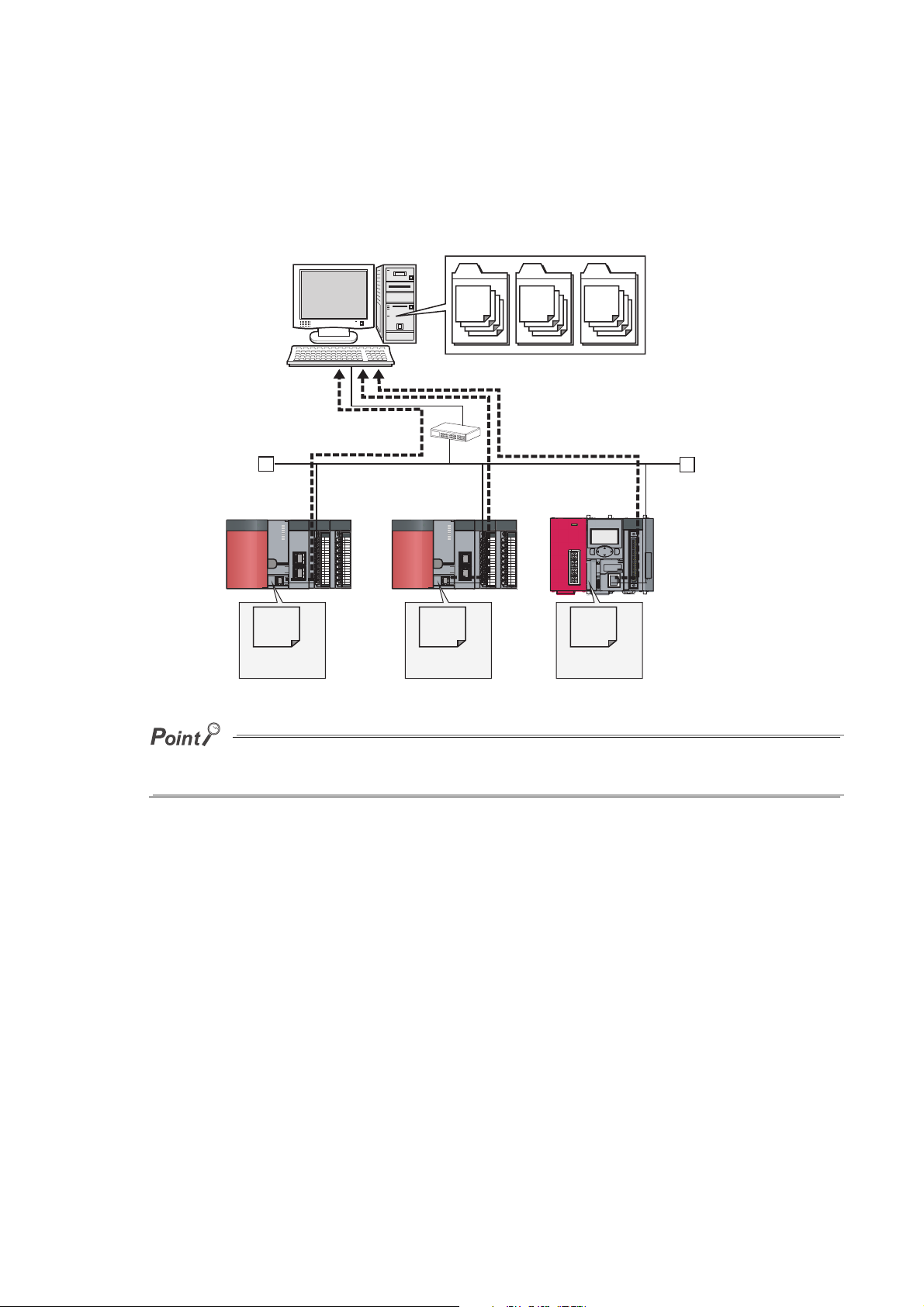
(8) Data logging files can be transferred from the CPU module to the FTP server
By using the data logging file transfer function, the CPU module serves as an FTP client, and data logging files in
SD memory cards can be transferred to the FTP server. ( Page 82, Section 7.4) Since data logging files can
be managed by one FTP server, data management and maintenance work can be reduced.
FTP server
QnUDVCPU
LOG01_
00000026
.csv
Data logging
file
SD memory card
Ethernet
LOG01_
00000001
.csv
QnUDVCPU
LOG02_
00000026
.csv
Data logging
file
SD memory card
LOG02_
00000001
.csv
LOG03_
00000001
.csv
LCPU
LOG03_
00000026
.csv
Data logging
file
SD memory card
The data logging file transfer function requires an FTP server. For details on the server, refer to the manual for the server
used.
24
CHAPTER 1 DATA LOGGING
:
CSV format
Device
values
Data logging file
Samples device values of the CPU module.
CPU module
SD memory card
Data logging
LCPU
or
QnUDVCPU
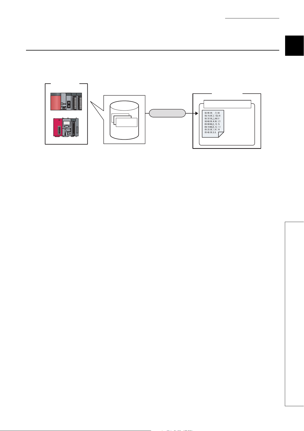
1.2 Processing Outline
Device values collected from the CPU module are stored in the data logging file in an SD memory card. All of the data
collected over the specified period can be stored, and these data can be analyzed in detail.
1
1.2 Processing Outline
25
CHAPTER 2 SYSTEM CONFIGURATION
Configuration tool
GX LogViewer
Personal
computer
SD memory card
(sold separately,
required)
QnUDVCPU
Settings displayed.
Settings configured.
Ethernet, CC-Link, or C24
QnUDVCPU LCPU LCPU
FTP server
*1
SD memory card
(sold separately,
required)
Connection from a USB or serial
port
*2
Connection from an interface board
*2
Connection via network modules
*2
SD memory card
(sold separately,
required)
SD memory card
(sold separately,
required)
This chapter describes a system configuration for executing the data logging function.
2.1 Overall System Configuration
An overall system configuration for executing the data logging function is shown below.
*1 The data logging file transfer function requires an FTP server. For details on the server, refer to the manual for the server
used.
*2 For connection, refer to Page 28, Section 2.1.2 and Page 31, Section 2.1.3.
For connection to the CPU module, refer to Page 32, Section 2.2.
26
CHAPTER 2 SYSTEM CONFIGURATION
2.1.1 Software
The following software can be used for data logging. For information on how to get and start it, refer to Page 46,
CHAPTER 5.
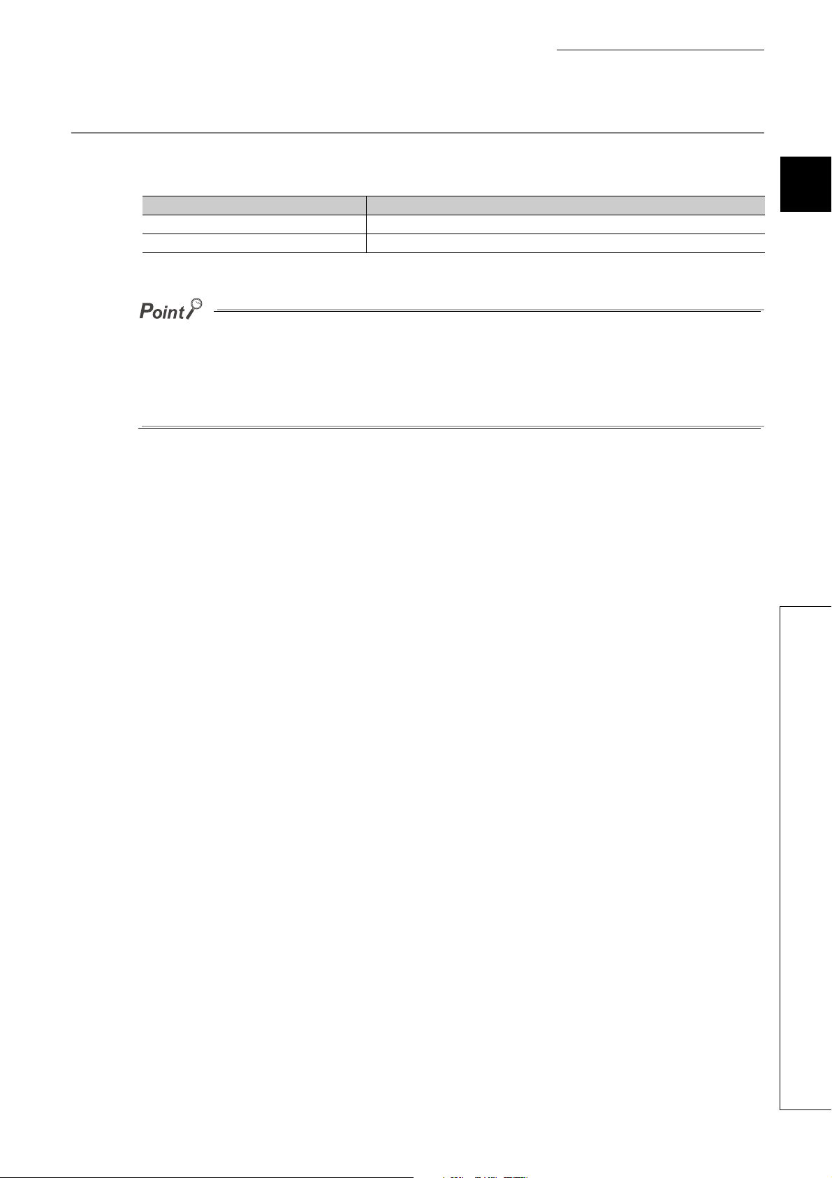
Name Description
CPU Module Logging Configuration Tool Software to configure data logging settings and to manage collected data
GX LogViewer Software to display data collected by data logging
● Some project files created or data logging settings configured by a new version of the configuration tool may not be read
by the older version. Use the latest version of the configuration tool. ( Page 46, Section 5.1)
● GX LogViewer is not an indispensable tool for executing the data logging function. Use it for graphical display of logged
data. This manual does not contain descriptions of GX LogViewer, unless otherwise required. For details on GX
LogViewer, refer to the following.
GX LogViewer Version 1 Operating Manual
2
2.1 Overall System Configuration
2.1.1 Software
27
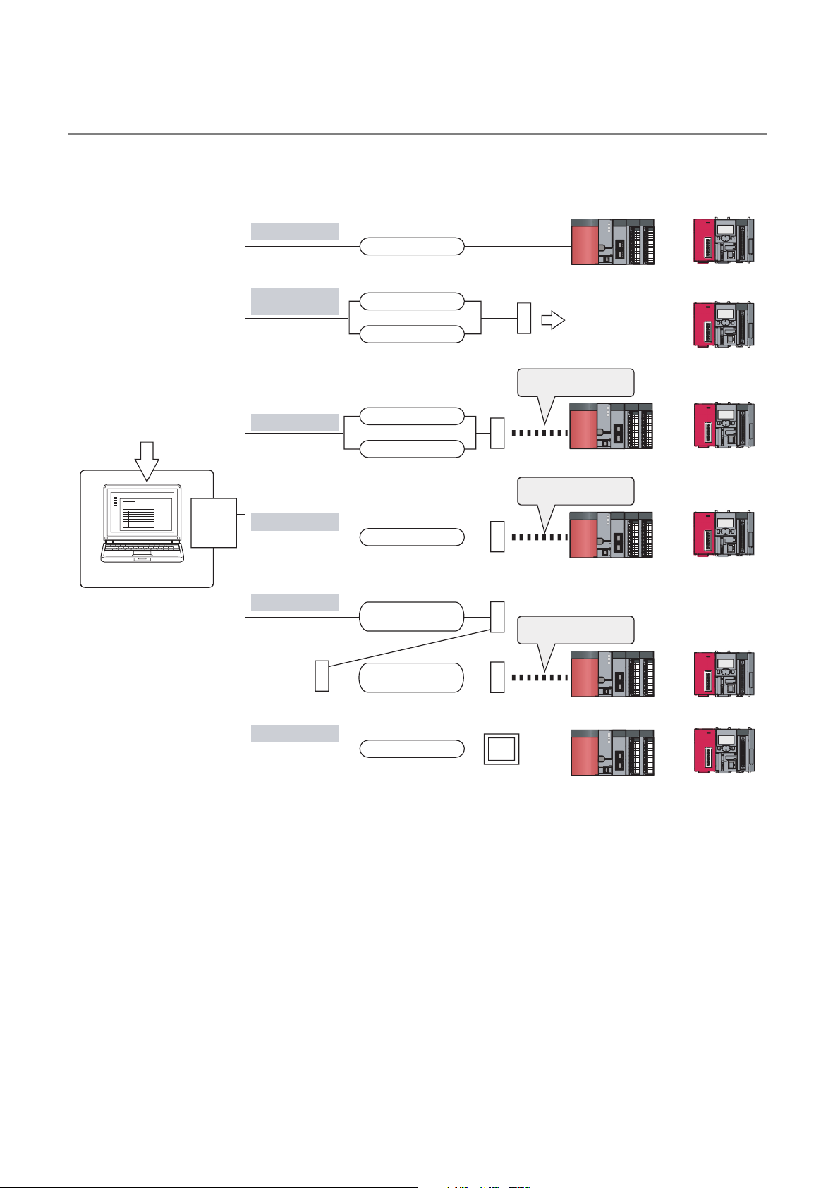
2.1.2 Connection from a USB or serial port
Configuration tool
Personal computer
USB or
serial
port
USB communication
Direct connection to
serial port
Via computer link
Via CC-Link (G4)
Via modem
Via GOT
Modem
Cable
Cable supplied with
modem
Converter/cable
Cable supplied with
modem
Converter/cable
RS-232 cable
QC30R2
USB cable
Converter/cable
GOT
C24
Modem
G4 module
G4-S3 module
C24
Serial communication link
CC-Link
Serial communication link
RS-232 adapter
LCPUQnUDVCPU
or
LCPUQnUDVCPU
or
LCPUQnUDVCPU
or
LCPUQnUDVCPU
or
LCPU
LCPUQnUDVCPU
or
The figure below shows configurations of the systems that are connectable through the USB or serial port of a
personal computer.
28

CHAPTER 2 SYSTEM CONFIGURATION
Connection from a personal computer with multiple USB ports to multiple CPU modules
Connection to multiple CPU modules via a USB hub
<Unavailable configuration>
USB cable
USB cable
USB cable
USB cable
USB
hub
Personal computer
Personal computer
USB
cable
LCPU
QnUDVCPU
or
LCPUQnUDVCPU
or
LCPUQnUDVCPU
or
LCPU
QnUDVCPU
or
(1) Using a USB cable
The following USB cable and adapter can be used.
• USB cable (USB A type USB miniB type)
• USB adapter (USB B type USB miniB type)
Install a USB driver when using a USB cable for the first time. ( Installing a USB Driver)
Only one CPU module can be connected at the same time. The following configurations are not available.
2
When connecting a personal computer to the CPU module with a USB/RS-232 conversion cable, confirm the COM port
number. For the confirmation method, refer to the manual for the cable.
2.1 Overall System Configuration
2.1.2 Connection from a USB or serial port
29

(2) Using an RS-232 cable
The following RS-232 cable has been tested for operation.
Model Manufacturer
QC30R2 (for D-sub 9-pin connector on personal computer)
For high-speed communication (transmission speed: 115.2/57.6kbps), use a personal computer that supports high-speed
communication. If a communication error has occurred, lower the transmission speed setting and retry the communication.
Mitsubishi Electric Corporation
(3) Access through a GOT
The transparent function of a GOT allows an access to the CPU module through the GOT. For details, refer to the
following.
GOT1000 Series Connection Manual (Mitsubishi Products) for GT Works3
GOT2000 Series Connection Manual (Mitsubishi Products) For GT Works3 Version1
30

CHAPTER 2 SYSTEM CONFIGURATION
Personal computer
MELSEC interface board
LCPUQnUDVCPU
or
(Another station)(Another station)
+ Driver
Standard interface board
LCPUQnUDVCPU
or
(Own station or
another station)
(Own station or
another station)
+ Driver
2.1.3 Connection from an interface board
The following figure shows configurations of the systems, in each of which the personal computer is connected to a
CPU module using an interface board installed in the personal computer. For the applicable interface boards and
details of a USB driver, refer to the manual for the interface board used.
Interface board name
MELSECNET/H interface board
CC-Link IE Controller Network interface board
MELSEC interface board
Standard interface board Ethernet interface board
CC-Link IE Field Network interface board
CC-Link Ver.1 interface board
CC-Link Ver.2 interface board
2
For the connectable CPU modules, refer to the manual for the interface board used.
TCP connection is recommended when devices are connected on Ethernet. For Ethernet direct connection or UDP
connection, it takes time to process the following:
• Opening the window of the configuration tool
• Logging file operation ( Page 152, Section 8.11)
For specifications of Ethernet communication, refer to the following.
QnUCPU User's Manual (Communication via Built-in Ethernet Port)
MELSEC-L CPU Module User's Manual (Built-In Ethernet Function)
2.1.3 Connection from an interface board
2.1 Overall System Configuration
31

2.2 Precautions for Ethernet Connection
This section describes precautions for connecting a personal computer to the CPU module over Ethernet.
(1) When the Windows Firewall setting is enabled
Disable the Windows Firewall setting.
(2) When multiple IP addresses are valid at the same time
Do not select direct connection setting when two or more IP addresses are valid at the same time as follows:
• To multiple Ethernet ports (network devices) of a personal computer, multiple IP addresses are assigned.
• Wireless LAN setting is enabled, in addition to the Ethernet port setting of the personal computer.
• To one Ethernet port of the personal computer, more than one IP address are assigned.
32

CHAPTER 2 SYSTEM CONFIGURATION
2.3 Operating Environment for the Configuration Tool
For the operating environment of the configuration tool, refer to the following files included in the installers:
CPU Module Logging Configuration Tool/GX LogViewer Installation Instructions (BCN-P5999-0506)
2
2.3 Operating Environment for the Configuration Tool
33

CHAPTER 3 SPECIFICATIONS
This chapter describes the specifications of the data logging function.
3.1 Function Specifications
The following lists the specifications of the data logging function.
Item Specifications Reference
Number of data logging settings 10
Data storage location
Logging type
Sampling interval
Data sampling
Number of data sampling points Up to 1280 (128 points per setting)
AND conjunction
Data processing Trigger logging
File name
File format CSV file
File output
Handling of output
files
Data type
Data output format (CSV file)
File
switching
Trigger condition
AND conjunction
Trigger logging range
Number of triggers 1
Number of trigger logging
records
File switching
timing
Number of saved files 1 to 65535
Standard ROM (configuration files only), SD memory
card
• Continuous logging
• Trigger logging
• Specification period logging
• Each scanning cycle
• Time specification
• Each multiple CPU high speed transmission cycle
• Condition specification (Device specification, Step No.
specification)
In the Sampling interval setting, Device and Step No.
under "Condition specification" can be specified in
combination (AND conjunction).
• Condition specification (Device change specification,
Step No. specification)
• When trigger instruction executed
• When data logging trigger activated
In the Trigger setting, Device data change and Step No.
under "Condition specification" can be specified in
combination (AND conjunction).
Data of the specified number of records are logged
before and after a trigger.
Up to 1000000
Additional information
•Bit
• Word (unsigned)
• Word (signed)
• Double word (unsigned)
• Double word (signed)
• Single-precision real number
• Double-precision real number
• Character string: 1 to 256 characters
• Numeric string: 1 to 256 bytes
• Decimal format
• Hexadecimal format
• Exponential format
• No. of records
• File size
*3
+ File number (serial number)
Page 48, CHAPTER 6
Page 56, Section 6.3
*4
*2
Page 50, Section 6.2
Page 57, Section
6.3.2,
Page 59, Section 6.3.2
(1)
Page 37, Section 3.3
Page 64, Section 6.5
34

Others
CHAPTER 3 SPECIFICATIONS
Item Specifications Reference
Data logging operation at transition to RUN
Auto logging by inserting an SD memory card
File access
Data logging file transfer function
*1
Specify the operation at the time of status change, from
power on to RUN, from reset to RUN, or from STOP to
RUN, after registration of the data logging setting.
By inserting an SD memory card (to which data logging
settings have been written), data logging automatically
starts.
The FTP server function allows saving and deletion of
data logging files from the SD memory card installed in
the CPU module to the personal computer.
Data logging files can be transferred from the CPU
module to the FTP server on LAN.
Page 77, Section 7.1
Page 78, Section 7.2
Page 81, Section 7.3
Page 82, Section 7.4
*1 Before using the data logging file transfer function with the LCPU, check the versions of the CPU module and
configuration tool used. ( Page 190, Appendix 2)
*2 The setting is available only for the High-speed Universal model QCPU and the Universal model Process CPU.
*3 For additional information, refer to Page 127, Section 8.4.12.
*4 The function is available only for the High-speed Universal model QCPU and the Universal model Process CPU. Before
using this function, check the versions of the CPU module and configuration tool used. ( Page 190, Appendix 2)
3
3.1 Function Specifications
35

3.2 Folder Structure
LOG03
LOG01
LOG02
:
18:55:16 65,725,36,1
18:55:17 66,756,36,0
18:55:18 67,723,36,0
18:55:19 68,741,36,0
18:55:20 69,712,36,1
18:55:20 70,724,36,1
18:55:20 71,732,36,1
18:55:20 72,733,
LOG01.CSV
00000101
00000001
:
18:55:16 65,725,36,1
18:55:17 66,756,36,0
18:55:18 67,723,36,0
18:55:19 68,741,36,0
18:55:20 69,712,36,1
18:55:20 70,724,36,1
18:55:20 71,732,36,1
18:55:20 72,733,
00000001.CSV
:
18:55:16 65,725,36,1
18:55:17 66,756,36,0
18:55:18 67,723,36,0
18:55:19 68,741,36,0
18:55:20 69,712,36,1
18:55:20 70,724,36,1
18:55:20 71,732,36,1
18:55:20 72,733,
00000002.CSV
:
18:55:16 65,725,36,1
18:55:17 66,756,36,0
18:55:18 67,723,36,0
18:55:19 68,741,36,0
18:55:20 69,712,36,1
18:55:20 70,724,36,1
18:55:20 71,732,36,1
18:55:20 72,733,
00000003.CSV
:
18:55:16 65,725,36,1
18:55:17 66,756,36,0
18:55:18 67,723,36,0
18:55:19 68,741,36,0
18:55:20 69,712,36,1
18:55:20 70,724,36,1
18:55:20 71,732,36,1
18:55:20 72,733,
LOG02.CSV
:
18:55:16 65,725,36,1
18:55:17 66,756,36,0
18:55:18 67,723,36,0
18:55:19 68,741,36,0
18:55:20 69,712,36,1
18:55:20 70,724,36,1
18:55:20 71,732,36,1
18:55:20 72,733,
LOG03.CSV
Stack file (setting No.1)
Stack file (setting No.2)
Stack file (setting No.3)
/
LOGGING
*1 *2
*3
*3
The following is the folder structure of an SD memory card that is installed in the CPU module. When an access is
made by the FTP function, " / " denotes that it is the root folder (directory) of the SD memory card.
*1 The folder name is fixed.
*2 Do not create any file or folder under the LOGGING folder using a personal computer.
*3 Delete unnecessary folders by:
• Using a personal computer
• Logging file operation ( Page 152, Section 8.11)
36
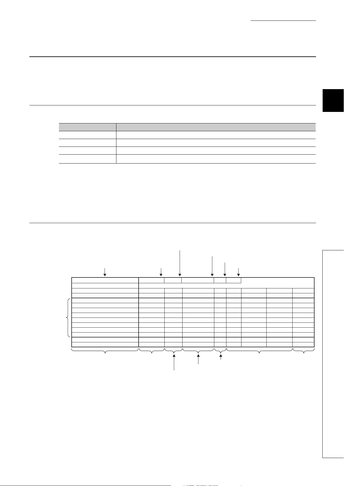
3.3 CSV File Output Format
Data line
File information line
Comment line
Data name line
Data type information line
File type File version
Data type information line number
Data name line number
Comment line number
Data start line number
Date column Data sampling
interval column
Execution step No. column
Execution program name column
Index column
Data column Trigger
information
column
[LOGGING]
LOGGING TEST
DATETIME[YYYY/MM/DD hh.mm.ss.s]
TIME
L1
INTERVAL
0
60000000
60000000
60000000
60000000
60000000
60000000
60000000
3
STEP NO.
STEP NO.
10
2
15
100
100
1
0
0
4
PROGRAM NAME
PROGRAM NAME
MAIN
MAIN1
MAIN1
MAIN2
MAIN2
MAIN
MAIN
MAIN
5
INDEX
INDEX
1
2
3
4
5
6
7
8
BIT[1;0]
FFFF
1
FFFF
1
FFFF
1
FFFF
1
M0
1
0
0
0
0
0
0
0
1234
1234
0
0
12345678
12345678
12345679
12345680
USHORT[HEX]
W30
LONG[DEC.0]
D100
2
TRIGGER[*]
Trigger
*
INTERVAL[µs]
2009/10/01 12:01:00,000
2009/10/01 12:02:00,000
2009/10/01 12:03:00,000
2009/10/01 12:04:00,000
2009/10/01 12:05:00,000
2009/10/01 12:06:00,000
2009/10/01 12:07:00,000
2009/10/01 12:00:00,000
This section describes the CSV format specifications and lines and columns output.
CHAPTER 3 SPECIFICATIONS
3.3.1 CSV format specifications
The CSV file format is specified as shown below.
Item Description
Delimiter Comma (,)
Line feed code CRLF (0x0D, 0x0A)
Character code ASCII or Shift JIS
Field data
*1 When "Output device comments for data column" is selected in "CSV output" of the data logging setting, if a double
quotation mark (" or ") or comma (,) is included in a device comment, the data must be as follows:
The entire data must be enclosed with double quotation marks (" ").
Embedded double quotation marks (" ") must be doubled.
Double quotation marks (" ") and commas (,) must not be included in each of data.
3.3.2 Output details of lines and columns
An example of the lines and columns output is shown below.
3
*1
3.3 CSV File Output Format
3.3.1 CSV format specifications
37

Output of the following information can be disabled. ( Page 125, Section 8.4.11)
• Date and time column
• Trigger information column (selectable only for trigger logging)
• Index column
• Data sampling interval column
• Execution program name column
• Execution step No. column
• Comment line
(1) File information line
Information on the file is displayed.
Item Description
File type [LOGGING] is output. 9 bytes
File version
Data type information line
number
Data name line number Line number indicating the Data name line is entered. 1 byte
Data start line number Line number indicating the first of the data lines is entered. 1 byte
Comment line number
File version (fixed to Q1 for High-speed Universal model QCPU and Universal model
Process CPU, or fixed to L1 for LCPU)
Line number indicating the Data type information line is entered. 1 byte
Line number indicating the Comment line is entered.
If the Comment line data are not to be output, this field is left blank.
*1
Size
2 bytes
0 to 1 byte
*1 The size of the File information line is the total of the following. (When outputting a comment)
9 (File type) + 2 (File version) + 1 (Data type information line number) + 1 (Line No. of Data name line number) + 1 (Data
start line number) + 1 (Comment line number) + 5 (number of commas) + 2 (CR + LF) = 22 bytes
(2) Comment line
A comment is displayed.
Item Description
Comment
*1 The size of the Comment line is the total of the following.
The size of the characters used for the comment (1 byte for each one-byte character, 2 bytes for each two-byte
character) + 2 (CR + LF)
A comment set in the configuration tool is output. (Up to 512 one-byte or 256 two-byte
characters can be output. If there is no setting, blank space is output.)
*1
Size
0 to 512 bytes
38

CHAPTER 3 SPECIFICATIONS
(3) Data type information line
The data type of each column is displayed. Data are output in the format of (data type) [(additional information)].
Item "Data type" output
Date and time column DATETIME 8 bytes
Data sampling interval
column
Execution step No. STEP NO. 8 bytes 0 bytes
Execution program
name column
Index column INDEX 5 bytes 0 bytes
Data column
Trigger information
column
INTERVAL 8 bytes
PROGRAM NAME 12 bytes 0 bytes
Bit type: BIT 3 bytes Bit type: [1;0] 5 bytes
16-bit integer (unsigned): USHORT 5 bytes
16-bit integer (signed): SHORT 6 bytes
32-bit integer (unsigned): ULONG 4 bytes
32-bit integer (signed): LONG 5 bytes
Single-precision floating point (32-bit): FLOAT 5 bytes
Double-precision floating point (64-bit):
DOUBLE
Character string type: STRING 6 bytes
Numeric string type: RAW 3 bytes
TRIGGER 7 bytes
Size
6 bytes
*1
"Additional information" output
A format is output.
Example: [YYYY/MM/DD hh:mm:ss.s]
None
Decimal format: [DEC.0] 7 bytes
Hexadecimal format: [HEX] 5 bytes
Exponential representation: [EXP, (number of
fractional digits)]
Character string or numeric string type: The
specified length of data (in byte units) is output.
[(Character string for indicating trigger
occurrence)] is output. (Semicolon (;), double
quotation marks (" ") and comma (,) cannot be
used.)
Size
3 to 34
bytes
0 bytes
7 to 8
bytes
3 to 5
bytes
3 to 34
bytes
*1
3
*1 For example, when 128 point decimal data is logged in the 16-bit integer (signed) format (when the date and time (in
"YYYY/MM/DD hh:mm:ss.s" format), data sampling interval, execution step No., execution program name, and index
columns are selected for output), the size of the data type information line is the total of the following.
(8 + 23) (date and time) + 8 (data sampling interval) + 8 (execution step No.) + 12 (execution program name) + 5 (index)
+ (5 + 7) 128 (data) + 132 (number of commas) + 2 (CR + LF) = 1734 bytes
3.3 CSV File Output Format
3.3.2 Output details of lines and columns
39

(4) Data name line
The data name of each column is displayed.
Item Description
Date and time column TIME is output. 4 bytes
Data sampling interval
column
Execution step No. STEP NO. is output. 8 bytes
Execution program name
column
Index column INDEX is output. 5 bytes
Data column
Trigger information column Trigger is output. 7 bytes
*1 The device comment of the comment file specified in the setting is displayed.
*2 Even if "Output device comments for data column" is selected, device No. is displayed when:
• No device comment is set.
• The specified device comment file does not exist.
• A digit-specified bit device is specified for sampling data.
• A bit-specified word device is specified for sampling data.
*3 For example, when 128 point data in D100 to D227 is logged (when the date and time, data sampling interval, execution
step No., execution program name, and index columns are selected for output, and when device No. is selected for the
data column), the size of the data name line is the total of the following.
4 (date and time) + 12 (data sampling interval) + 8 (execution step No.) + 12 (execution program name) + 5 (index) + (4
128) (data) + 132 (number of commas) + 2 (CR + LF) = 687 bytes
INTERVAL [us] is output. 12 bytes
PROGRAM NAME is output. 12 bytes
"Device No." or "Device comment"
*1*2
specified in the setting is displayed.
*3
Size
1 to 32 bytes
40

(5) Data line
Sampled data values are displayed. One line contains the data sampled at one time.
Item Description
Date and time column
Data sampling interval
column
Execution step No.
Execution program name
column
Index column
Data column
Trigger information
column
CHAPTER 3 SPECIFICATIONS
*11
Size
Date and time information is output.
A time interval between the previous and current sampling events is output.
(Unit: s, Range: 1 to 100000000000)
An execution step No. is output.
An execution program name is output.
An index No. of the data sampled in data logging is output.
(Range: 1 to 4294967295)
When bit is specified: Bit ON = 1, or bit OFF = 0 is output. 1 byte
When unsigned word or double-word type is specified: Data are output in the format specified
among decimal, hexadecimal, and exponential formats.
When signed word or double-word type is specified: Data are output in the format specified
among decimal, hexadecimal, and exponential formats.
When single- or double-precision real number is specified: Data are output in the specified
*10
decimal
"NaN" is output in the data line. For the value range applicable to each real number type, refer
to Page 42, Section 3.3.3.
When character string type is specified: A string of characters in the specified size is output. If
"0" is included in the data, the data after the "0" is not output because it indicates the end of
the string.
When numeric string type is specified: Data are converted into hexadecimal characters in byte
units, and output without any space.
The line, where a trigger has occurred, is output. 0 to 32 bytes
or exponential format. When the specified data type is not applicable to the data,
*5
*12
*1
*2
*6*7
*8*9
*3
*4
Hexadecimal format: 1 to 4 bytes
Exponential format: 5 to 21 bytes
Hexadecimal format: 1 to 8 bytes
Exponential format: 5 to 22 bytes
1 to 32 bytes
1 to 12 bytes
1 to 6 bytes
1 to 8 bytes
1 to 10 bytes
Decimal format: 1 to 6 bytes
Decimal format: 1 to 11 bytes
1 to 256 bytes
2 to 512 bytes
3
3.3 CSV File Output Format
3.3.2 Output details of lines and columns
*1 At the first sampling, "0" is stored.
*2 When the upper limit of the display range is exceeded, the value returns to 1, and the time interval measured again is
output.
*3 If any data are missed to be sampled, the index value is reset to 1.
*4 When the maximum value is exceeded, it returns to 1 and is incremented again.
*5 Characters other than ASCII and Shift-JIS code characters, double quotation marks (" "), commas (,), and semicolons (;)
are replaced with periods (.).
*6 If the timing of sampling coincides with a system operation (such as a system interrupt), "0" is output.
*7 When "Each scanning cycle" is set to "Sampling", the step No. of the END instruction in the last program executed is
output.
*8 If the timing of sampling coincides with a system operation (such as a system interrupt), "*SYSTEM" is output.
*9 When "Each scanning cycle" is set to "Sampling", the name of the last program executed is output.
*10 When the value to be output is outside the range of -2147483648.0 to 4294967295.0, it is displayed in the format
equivalent to "exponential representation and 9 fractional digits".
*11 For example, when 128 point data in D100 to D227 is logged in the unsigned word type format (when the date and time
(in "YYYY/MM/DD hh:mm:ss.s" format), data sampling interval, execution step No, execution program name, and index
columns are selected for output), the size of the data line is the total of the following.
21 (date and time) + 12 (data sampling interval) + 6 (execution step No.) + 8 (execution program name) + 10 (index) + (6
128) (data) + 132 (number of commas) + 2 (CR + LF) = 959 bytes
*12 When a CSV file is opened in Excel, the date and time column is displayed in the default format of Excel. Format the
cells if needed. For example, to display information of year, month, day, time, minute, second, and millisecond, specify
the following user defined display format.
yyyy/mm/dd hh:mm:ss.000
41

3.3.3 Value ranges by output format
This section describes the value ranges available for each output format.
(1) Integer type
The value range available for each integer type is shown below.
Output format Lower limit Upper limit
Word (unsigned) 0 65535
Word (signed) -32768 32767
Double word (unsigned) 0 4294967295
Double word (signed) -2147483648 2147483647
(2) Real number type
The value range available for each real number type is shown below.
Output format
Single-precision
real number
Double-precision
real number
Lower limit Upper limit Lower limit Upper limit
-3.4028235E+38 -1.401298E-45 1.401298E-45 3.4028235E+38
-1.79769313486231570E+308 -4.94065645841246544E-324 4.94065645841246544E-324 1.79769313486231570E+308
Negative value Positive value
If the output value is out of the range specified above, the following value is output.
• +Inf: when the value exceeds the upper limit of positive values
• -Inf: when the value falls below the lower limit of negative values
• 0: when the value is between the upper limit of negative values and the lower limit of positive values
Output format -Inf 0 +Inf
Single-precision real number 0xff800000 0x00000000 0x7f800000
Double-precision real number 0xfff0000000000000 0x0000000000000000 0x7ff0000000000000
42

3.4 Size of Data Logging Setting File
The size of a data logging setting file is the total of the following:
• Size of a common setting data file
• Size of individual setting data files of setting No.1 to setting No.10
CHAPTER 3 SPECIFICATIONS
(1) Size of a common setting data file
The size is the total of the following:
Item Size (byte) Quantity
Common header 64 1
File information 4 1
Data logging common setting area 28 1
(2) Size of individual setting data files
The size is the total of the following:
Item Size (byte) Quantity
Common header 64 1
File information 4 1
Data logging common setting area 36 1
Sampling information 114 1
Trigger condition setting/specification period condition setting
information
Output setting information 772 1
Storage setting information 46 1
Data logging sampling data area (information) 4 1
Data logging sampling data area (number of points) 10 Total number of data points
Data logging sampling data area (setting) 8 Number of set data
Optional information 2 1
Extension function bit 2
Extension function setting 1 (data logging file
transfer function) setting data size
Extension
function
setting
Extension function
setting 1 (data logging
file transfer function)
setting contents
Common area (size fixed) 14
FTP server (IP address)
Login user name
Login password
Directory path
Total of the following setting 1 items:
122 1
Total of the following:
2
7 to 15
1 to 32
0 to 32
1 to 64
*1
*2
*2
*2
*2
3
3.4 Size of Data Logging Setting File
1
*1 When the extension function setting is the default, the size is 0 bytes.
*2 The size (byte) is the number of characters of each item.
43

CHAPTER 4 PROCEDURES AND SETTINGS
CPU module
Start
Personal computer
Insert an SD memory card into the slot of the CPU module.
Install the configuration tool.
Power on the CPU module
Start the configuration tool.
Set the CPU module switch to RUN. Configure data logging settings.
Select a communication route in the "Transfer
Setup" dialog box of the configuration tool.
Connect the personal computer to the CPU module.
Write the settings to the CPU module.
Start data logging.
End
BEFORE SYSTEM OPERATION
The following flowchart shows the steps to be performed before data logging operation.
Page 47, Section 5.2
Page 47, Section 5.3
Page 110, Section 8.4
Page 136, Section 8.6
Page 145, Section 8.8
Page 149, Section 8.10
For installation of the CPU module, power supply module, and SD memory card, and the installation environment, refer to
the following.
User's Manual (Hardware Design, Maintenance and Inspection) for the CPU module used
44

Memo
CHAPTER 4 PROCEDURES AND SETTINGS BEFORE SYSTEM OPERATION
4
45

CHAPTER 5 START-UP OF THE CONFIGURATION
TOOL
This chapter describes the procedure for starting the configuration tool.
5.1 Getting the Configuration Tool
The configuration tool is included in the programming tool.
(1) Programming tools that include the configuration tool
The configuration tool is included in the CD-ROM of the following programming tools. Applicable versions are as
follows:
Relevant CPU module
High-speed Universal model QCPU
Universal model Process CPU
LCPU 1.20W or later 8.89T or later
*1
*1
GX Works2 GX Developer
1.98C or later Not supported
1.492N or later Not supported
configuration tool
*1 For the configuration tool version, which is compatible with the High-speed Universal model QCPU and Universal model
Process CPU, refer to Page 190, Appendix 2.
46

CHAPTER 5 START-UP OF THE CONFIGURATION TOOL
Remark
5.2 Installing/Uninstalling the Configuration Tool
For the installation/uninstallation procedures, refer to the following manual included in the installer.
CPU Module Logging Configuration Tool/GX LogViewer Installation Instructions (BCN-P5999-0506)
5.3 Starting the Configuration Tool
There are three ways to start the configuration tool:
• From the Start menu
• From the programming tool
• From GX LogViewer
(1) Start from the Start menu
After installing the configuration tool, follow the procedure below.
[Start] [All programs] [MELSOFT Application] [Logging] [CPU Module Logging
Configuration Tool]
5
(2) Start from the programming tool
After starting the programming tool, follow the procedure below.
[Tool] [Logging Configuration Tool]
(3) Start from GX LogViewer
Refer to the following.
GX LogViewer Version 1 Operating Manual
5.4 Switching a Display Language
The configuration tool supports multiple display languages so that the display language can be changed from the
menu bar on the same personal computer screen.
(1) Operating procedure
[View] [Switch Display Language]
(2) Precautions
If the language different from the operating system is set, the language might not be displayed properly, (e.g.: A
word is cut off in the middle, or a line is cut off lengthwise.)
5.2 Installing/Uninstalling the Configuration Tool
Before switching the display language, check the versions of the configuration tool used. ( Page 190, Appendix 2)
47

CHAPTER 6 DATA LOGGING FUNCTION
2009/01/10 10:15:18
2009/01/10 10:15:19
2009/01/10 10:15:20
2009/01/10 10:15:21
2009/01/10 10:15:22
OFF, 10
ON, 11
ON , 12
ON , 11
OFF, 10
LCPUQnUDVCPU
or
SD memory card
CPU module
Word device
Bit device
Data
logging file
(CSV format)
Trigger logging
(when condition(s)
is met)
*1
Continuous logging
(continuously)
*1
Specification period
logging (while
conditions are met)
*1
Sampling interval
Target data
*2
The data logging function allows logging of CPU module device values at the specified sampling intervals. The logged
data are stored on an SD memory card.
*1 For the type of logging, refer to Page 56, Section 6.3.
*2 For the target data, refer to Page 49, Section 6.1.
A block of the target data, which are collected according to the same sampling interval and logging type settings, is
referred to as a data logging setting. Up to 10 data logging settings can be configured with the data logging function.
( Page 110, Section 8.4)
48

CHAPTER 6 DATA LOGGING FUNCTION
6.1 Target D ata
The target data is device memory data in the CPU module, which is saved on an SD memory card with time stamp.
(1) Data type
The following data types can be specified for data logging of the device memory.
Data type Number of device points Data type Number of device points
Bit 1 Single-precision real number 2
Word (unsigned) 1 Double-precision real number 4
Double word (unsigned) 2 Character string
Word (signed) 1
Double word (signed) 2
Numeric string
*1 The specified size ranges from 1 to 256.
The number of points is calculated for each setting No. and the total number of points is used. In the following case, the total
number of points is eight.
• Setting No.1 Data type (Character string), specified size (1) 1 point
• Setting No.2 Data type (Character string), specified size (5) 3 points
• Setting No.3 Data type (Double-precision real number) 4 points
Specified size/2
Specified size/2
*1
*1
6
(2) Devices available for sampling
The following lists the devices whose data can be specified as sampling data.
Typ e Description
X (DX), Y (DY), M, L, F, SM, V, B, SB, T (contact)
*4
, C (contact)*3, C (coil)*4, FX, FY, BL\S, J\X*5, J\Y*5,
*5
*6
, J\B
*5
, J\SW*5, U3E\G
*5
*6
, J\B
*6
*1
, J\W*5, J\SW*5, U3E\G
Bit device
Word device
ST (coil)
J\SB
Bit specification of word device:
D, D (extended data register), SD, W, W (extended link register), SW, R, ZR, FD, U\G
J\W
T (current value), ST (current value), C (current value), D, D (extended data register), SD, W, W (extended link
register), SW, R, Z, ZR, FD, U\G
Digit specification of bit device*2: X, Y, M, L, F, SM, V, B, SB, BL\S, J\X*5, J\Y*5,
J\SB
*1 The built-in I/O function does not support the U\G specification.
*2 Digit specification of bit device is available only for K1 to K8.
*3 T (contact), ST (contact), and C (contact) are specified with TS, SS, and CS respectively.
*4 T (coil), ST (coil), and C (coil) are specified with TC, SC, and CC respectively.
*5 Before specifying the device, check the versions of the CPU module and configuration tool used. ( Page 190,
Appendix 2)
*6 The LCPU does not support this item.
For the above devices (except for FX, FY, FD, BL\S, and bit specification of word device), index modification
can be specified although indirect specification is not allowed.
*3
, T (coil)*4, ST (contact)*3,
*6
*1
,
6.1 Target Data
49

6.2 Sampling of Target Data
Sampling
Scan time Scan time Scan time Scan time Scan time
Program 0 END
Sampling
0 END
Sampling
0 END
Sampling Sampling
0 END 0 END
END processing END processing END processing END processing END processing
Select a sampling interval and timing from the following items. ( Page 115, Section 8.4.4)
Setting item Description
Each scanning cycle Data are collected in the END processing of each scan.
Sample data at the first END processing after the specified time
Time
specification
Each multiple CPU high speed transmission cycle
Condition
specification
has elapsed
Samples data at the specified time interval.
• When the bit of the bit device rises
• When the bit of the bit device falls
Device specification
Step No. specification
• When the word device value meets
the specified value
• When the word device data is
changed
• Always
• When execution condition is ON
• When execution condition is OFF
• When execution condition rises
• When execution condition falls
*1
Specify the time of sampling interval. Data are collected in
the END processing after the specified time has elapsed.
Specify the time of sampling interval. Data are collected at
the specified time intervals.
Data are collected in synchronization with the multiple
CPU high speed transfer cycle in a multiple CPU system
where the multiple CPU high speed transmission function
is used.
Data are collected when the specified device condition is
met in the END processing of each scan.
Data are collected during execution of the specified step
and when the specified condition is met.
*1 The LCPU does not support this item.
(1) Each scanning cycle
Data are collected in the END processing of each scan.
(2) Time specification
Data are collected at the specified time intervals. The setting range is as follows:
• Millisecond: 1 to 32767 (in increments of 1ms)
• Second: 1 to 86400 (in increments of 1s)
*1
50
*1 In the following cases, scan time will be extended and a watchdog timer error will occur. Pay attention to the sampling
interval and timing or the time spent for one data logging processing.
Short sampling interval, and many data logging executions per scan
Large volume of data to be collected, and long data logging processing time

CHAPTER 6 DATA LOGGING FUNCTION
Ex.
Ex.
100 ms 100 ms 100 ms
Program 0 END
END processing
Sampling
0 END
END processing
0 END
END processing
Sampling
0 END 0 END
END processing END processing
Time
specification
1 scan
Time specification
Sampling
5 ms
Sampling
5 ms 5 ms
(a) Sample data at the first END processing after the specified time has elapsed
Select this when data are to be collected at relatively long intervals and at the timing of END processing, not
during any other program execution.
When 100 milliseconds are specified
Specify a time value larger than the scan time. When scan time is longer than the time specified, even if more than one
sampling timing occur within one scan, only one sampling is performed in the END processing.
6
(b) Samples data at the specified time interval
*1
Select this when data are to be collected at relatively short intervals and in real time.
When 5 milliseconds are specified
*1 Even if clock data are changed during execution of data logging, actual sampling interval will not be changed.
6.2 Sampling of Target Data
51

(3) Each multiple CPU high speed transmission cycle (High-speed Universal
Ex.
Ex.
Sampling
Interrupt
program
execution
0.88 ms
Interrupt
Sampling
Interrupt
program
execution
0.88 ms
Interrupt
Interrupt
program
execution
Interrupt
Interrupt
program
execution
Interrupt
Sampling
Interrupt
program
execution
0.88 ms
Interrupt
Interrupt
program
execution
0.88 ms 0.88 ms 0.88 ms 0.88 ms
Interrupt
Interrupt
program
execution
Interrupt
Each multiple
CPU high-speed
transmission cycle
1 scan
Program 0 END
END processing
Sampling
0 END
END processing
Sampling
0 END
END processing
0 END 0 END
END processing END processing
Data are not sampled because the
condition is not met at END processing.
Specified value ≠
current value
Specified value ≠ current value
Specified value = current value
Word device
value
model QCPU and Universal model Process CPU only)
After the I45 interrupt program is executed, data are collected at the specified interval.
When the interval is set to 3
Data can be collected only when the following conditions are all met.
• A multiple CPU high-speed main base unit (Q3DB) is used.
• The system contains two or more CPU modules (multiple CPU system), and the use of the multiple CPU highspeed transmission function is enabled.
• The program includes an interrupt pointer (I45).
• The EI instruction is being executed, and the interrupt pointer (I45) is not masked.
(4) Condition specification
Data are collected when the state of the specified device or step meets the specified condition. Furthermore, if
both of (a) and (b) are selected, an AND condition can be created.
(a) Device specification
Data are collected when the specified device condition is met in the END processing of each scan.
<Data are continuously collected while the condition is satisfied.>
While the condition of the specified device is met, device data are collected in the END processing of each
scan. Set the following.
• When the word device value meets the specified value: When the current value of the specified device is
the specified value
When the word device value meets the specified value
52

CHAPTER 6 DATA LOGGING FUNCTION
Ex.
<Data are collected only when the status is changed.>
Device data are collected only in the END processing of the scan where the specified device condition is
changed. Set the following.
• When the bit of the bit device rises: When the specified device is turned on
• When the bit of the bit device falls: When the specified device is turned off
• When the word device data is changed: When the current value of the specified device is changed
When the word device data is changed
Word device
value
Program
Bit device
Word device
Specified value =
0 (initial value)
0 END
END processing
0 END
END processing
Specified value = 1 Specified value = 2
0 END
END processing
1 scan
Sampling
Data are not sampled because the status did not change
after the previous sampling.
The following devices can be specified as device data conditions.
Typ e Description
X, Y, M, L, F, SM, V, B, SB, T (contact)
*4
, J\Y*4, J\SB*4, J\B
J\X
Bit specification of word device:
D, D (extended data register), SD, W, W (extended link register), SW, R, ZR, FD, U\G
*4
, J\SW*4, U3E\G
J\W
T (current value), ST (current value), C (current value), D, D (extended data register), SD, W, W (extended link
register), SW, R, Z, ZR, FD, U\G
Digit specification of bit device*2:
X, Y, M, L, F, SM, V, B, SB, BL\S, J\X
*5
*3
, ST (contact)*3, C (contact)*3, FX, FY, BL\S,
*5
*1
, J\W*4, J\SW*4, J\B
*4
, J\Y*4, J\SB*4, U3E\G
0 END 0 END
END processing END processing
Sampling
*1
,
*5
*5
6
6.2 Sampling of Target Data
*1 The built-in I/O function does not support the U\G specification.
*2 Digit specification of bit device is available only for K1 to K4.
*3 T (contact), ST (contact), and C (contact) are specified with TS, SS, and CS respectively.
*4 Before specifying the device, check the versions of the CPU module and configuration tool used. ( Page 190,
Appendix 2)
*5 The LCPU does not support this item.
For the above devices, the following modification is available.
• Indirect specification
• Index modification (except for FX, FY, FD, BL\S, and bit specification of word device)
53

(b) Step No. specification
Ex.
END processing
END processing END processing
Sampling
Sampling
Specified step
Executed
Not
executed
Program
Data are not sampled because
the specified step is Not Executed.
0 END 0 END 0 END 0
Data are collected when the specified condition is met immediately before execution of the specified step. In
addition to "Step No.", set "Program name" and "Execution condition".
<Data are continuously collected while the condition is satisfied.>
Select an execution condition from the following.
• Always: Any time regardless of the operation status immediately before the execution of the specified step
• When the specified condition is ON: The operation status immediately before the execution of the
specified step is the Executed state.
• When the specified condition is OFF: The operation status immediately before the execution of the
specified step is the Not Executed state.
When the specified condition is ON
54

CHAPTER 6 DATA LOGGING FUNCTION
Ex.
Data are sampled because Not Executed
has changed to Executed.
Data are not sampled because the operation status
has not changed after the previous sampling.
END processing
END processing
END processing
Sampling
Specified step
Executed
Not
executed
Program 0 END 0 END 0 END 0
<Data are collected only when the status is changed.>
Select an execution condition from the following.
• When the specified condition rises: The operation status immediately before the execution of the specified
step has changed from Not Executed to Executed.
• When the specified condition falls: The operation status immediately before the execution of the specified
step has changed from Executed to Not Executed.
When the specified condition rises
6
● Data are collected when the status immediately before execution of the specified step changes to the specified status.
● With the High-speed Universal model QCPU and Universal model Process CPU, only the first data which satisfies the
specified conditions is collected if the step between the FOR and NEXT instructions is specified.
6.2 Sampling of Target Data
55

6.3 Logging Type
The data configured in the configuration tool are
collected and saved to an SD memory card.
: User operation
: Operation of CPU module
<Preparation for continuous logging>
Configure data logging settings in the
configuration tool, and write them to the CPU
module.
<Start of continuous logging>
*3
Start data logging by the start operation from the
configuration tool.
*4
<Data sampling>
<Completion of continuous
logging>
*3
When the specified number of saved files is
reached, the logging is completed.
*4
<Pause of continuous logging>
*3
By the following operation, data logging pauses
with the data logging settings registered.
• Pause operation from the configuration tool
• Turning off the special relay (data logging start)
<Stop of continuous logging>
*3
By the following operation, registration of the data
logging setting in the CPU module is cancelled.
• Stop operation from the configuration tool
<Reading of continuous logging
results>
*3
Specify a file in the SD memory card, and read
out the data logging results.
*4
*1
*2
*5
There are three logging types:
• Continuous logging
• Trigger logging
• Specification period logging
6.3.1 Continuous logging
When continuous logging is selected, device values of the CPU module are continuously logged at the specified
intervals. The flow of the continuous logging is shown below.
*1 Data logging can be resumed by performing the following from the pause status.
*2 Logging data are regarded as being saved until the entire buffer data are saved in the SD memory card.
*3 For the data logging status, refer to Page 63, Section 6.4.
*4 For the configuration tool, refer to Page 95, CHAPTER 8.
*5 The data logging results can be read because the data logging file is created even when the data logging has not been
Start operation from the configuration tool ( Page 131, Section 8.4.14)
Turning on the special relay (Data logging start)
completed.
56

CHAPTER 6 DATA LOGGING FUNCTION
The data configured in the configuration tool
are collected and saved to an SD memory
card.
:User operation
:Operation of CPU module
<Preparation for trigger logging>
Configure data logging settings in the
configuration tool, and write them to the
CPU module.
<Start of trigger logging>
*3
Start data logging by the start operation
from the configuration tool.
*4
<Data sampling>
<Completion of trigger logging>
*3
When data of the specified number of
records are collected and written to the SD
memory card, the trigger logging is
completed.
*4
<Pause of trigger logging>
*3
By the following operation, data logging
pauses with the data logging settings
registered.
• Pause operation from the configuration tool
• Turning off the special relay (data logging
start
<Stop of trigger logging>
*3
By the following operation, registration of the
data logging setting in the CPU module is
cancelled.
• Stop operation from the configuration tool
<Reading of trigger logging results>
*3
Specify a file in the SD memory card, and
read out the data logging results.
*4
*1
<Waiting for trigger>
Wait for the trigger condition
*5
*2
6.3.2 Trigger logging
When trigger logging is selected, device values of the CPU module before and after a trigger (satisfaction of the
specified condition) are logged for the specified number of records. The flow of the trigger logging is shown below.
6
*1 Data logging can be resumed by performing the following from the pause status.
*2 Logging data are regarded as being saved until the entire buffer data are saved in the SD memory card.
*3 For the data logging status, refer to Page 63, Section 6.4.
*4 For the configuration tool, refer to Page 95, CHAPTER 8.
*5 For the trigger condition, refer to Page 59, Section 6.3.2 (1).
Start operation from the configuration tool ( Page 147, Section 8.9)
Turning on the special relay (Data logging start)
6.3 Logging Type
6.3.2 Trigger logging
57
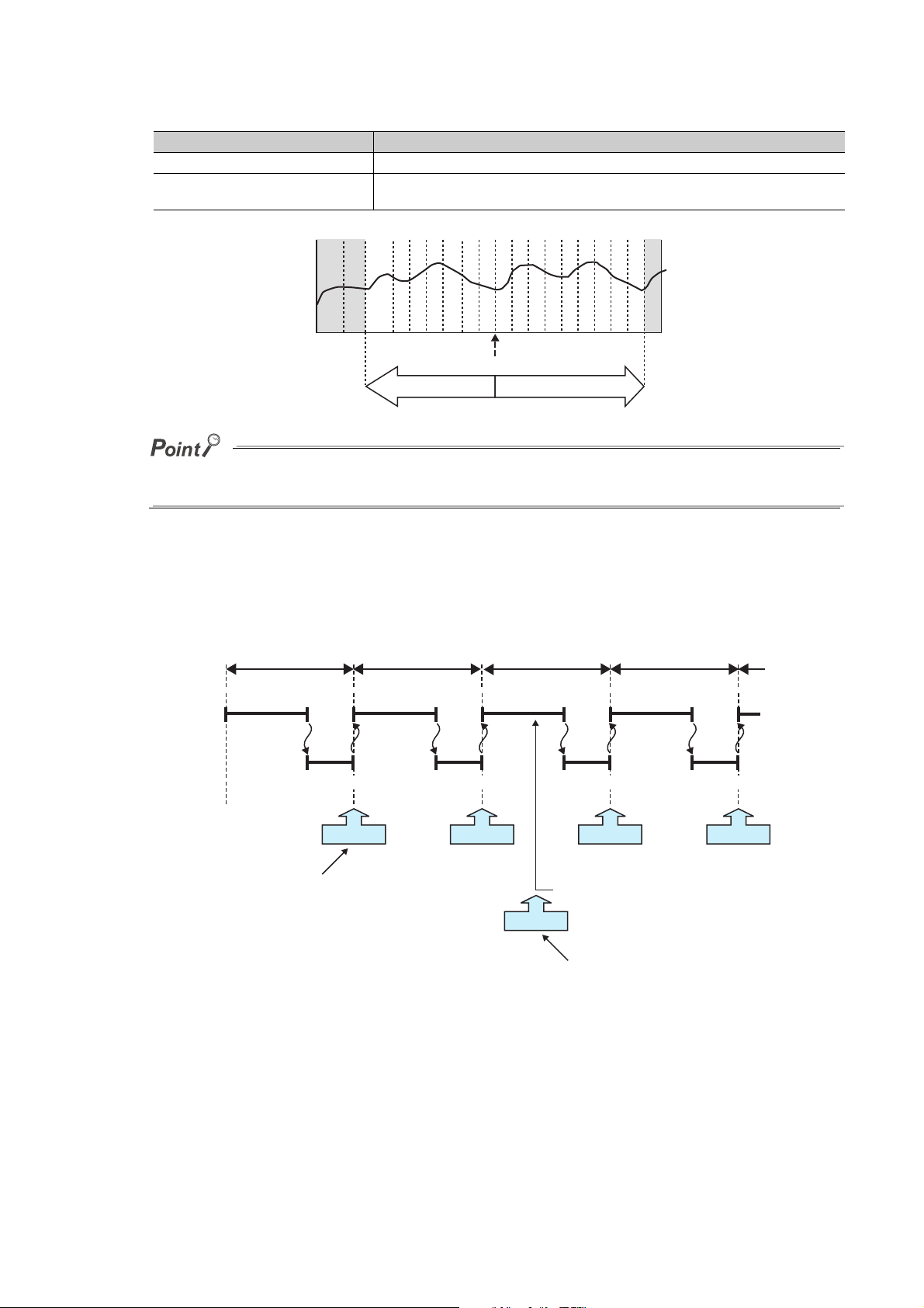
Specify the numbers of records before and after trigger in the following setting. ( Page 124, Section 8.4.10)
Sampling
Scan time Scan time Scan time Scan time
Program 0 END
Sampling
0 END
Sampling
0 END
Sampling
Sampling
0 END 0
END processing END processing END processing END processing
Data sampling at the specified intervals or timing
("Each scanning cycle" in this case)
Data sampling by trigger
Condition occurred
Setting item Description
No. of records (before trigger) Specify the volume of the data sampled before trigger as the number of records.
No. of records (after trigger)
Device value
After starting data logging, if the trigger condition is met before data collection of the specified number of records (before
trigger) is completed, the number of sampled records will be less than the specified.
Specify the volume of the data sampled after trigger (including at the time of trigger) as the
number of records.
Time
Trigger
No. of records before trigger
No. of records after trigger
With trigger logging setting, the specified data are collected at the specified interval or timing. Data of the specified
number of records before and after the trigger are extracted from the collected data, and saved in a data logging file in
the SD memory card.
Note that, in addition to the specified interval or timing, data are also collected when the trigger condition is met.
58

(1) Trigger condition
Specify a trigger condition by selecting appropriate items from the following.
Setting item Description
Device change
specification
Condition
specification
Step No.
specification
When trigger instruction executed
When data logging trigger activated
When the bit of the bit device
rises
When the bit of the bit device
falls
When the word device value
meets the specified value
When data are written to a
word device
Always
When execution condition is ONA trigger occurs any time but only during operation execution of the
When execution condition is
OFF
When execution condition
rises
When execution condition
falls
A trigger occurs when the status of the specified device is changed
from off to on.
A trigger occurs when the status of the specified device is changed
from on to off.
A trigger occurs when the data that match the specified value are
*2
written
(match or not match with the specified value).
A trigger occurs when data are written
A trigger occurs any time regardless of the operation status of the
specified step.
specified step.
A trigger occurs only not during operation execution of the specified
step.
A trigger occurs when the operation nonexecutable status of the
specified step is changed to the executable status.
A trigger occurs when the operation executable status of the specified
step is changed to the nonexecutable status.
A trigger occurs when the trigger logging set instruction (LOGTRG) is
executed.
A trigger occurs when the special relay (Data logging trigger) is turned
on.
CHAPTER 6 DATA LOGGING FUNCTION
*1
( Page 121, Section 8.4.8)
, regardless of the current value status of the specified device
*2
to the specified device.
6
*1 The following cases are not regarded as trigger conditions.
When a trigger condition is met again after occurrence of the trigger
When a trigger condition is met with no data sampling performed
*2 A trigger will also occur in a case other than program execution (such as link refresh, transient update, or a device test
conducted from a peripheral device).
(a) Condition specification
A trigger occurs when the state of the specified device or step meets the specified condition.
• Device change specification
A trigger occurs when the specified device condition is met. Select one from the following.
Item Description
When the bit of the bit device rises When the specified device is turned on
When the bit of the bit device falls When the specified device is turned off
A trigger occurs when the data that match the specified value are
When the word device value meets the specified value
When data are written to a word device When data are written to the specified device
The following devices can be specified as trigger conditions.
Typ e Description
*1
Bit device
Word device
X, Y, M, L, F, SM, V, B, SB, T (contact)
Bit specification of word device: D, D (extended data register), SD, W, W (extended link register), SW, R, ZR, FD
T (current value), ST (current value), C (current value), D, D (extended data register), SD, W, W (extended link register),
SW, R, ZR, FD
, ST (contact)*1, C (contact)*1, FX, FY
written, regardless of the current value status of the specified device
(match or not match with the specified value).
6.3 Logging Type
6.3.2 Trigger logging
*1 T (contact), ST (contact), and C (contact) are specified with TS, SS, and CS respectively.
For the above devices, index modification and indirect specification are not available.
59

• Step No. specification
Ex.
END processing
END processing END processing
Sampling
Trigger
Specified step
Executed
Not
executed
Program 0 END 0 END 0 END 0
Data sampling before trigger
Data sampling after trigger
Changed from Not Executed to Executed
A trigger occurs when the specified condition is met immediately before execution of the specified step. In
addition to "Step No.", set "Program name" and "Execution condition". Select an execution condition from
the following.
Item Description
Always
When the specified condition is ON
When the specified condition is OFF
When the specified condition rises
When the specified condition falls
Any time regardless of the operation status immediately before the execution of the
specified step
The operation status immediately before the execution of the specified step is the
Executed state.
The operation status immediately before the execution of the specified step is the Not
Executed state.
The operation status immediately before the execution of the specified step has
changed from Not Executed to Executed.
The operation status immediately before the execution of the specified step has
changed from Executed to Not Executed.
When the specified condition rises
● A trigger occurs when the status immediately before execution of the specified step changes to the specified status.
● With the High-speed Universal model QCPU and Universal model Process CPU, a trigger occurs only when the specified
conditions are satisfied for the first time if the step between the FOR and NEXT instructions is specified.
(b) When trigger instruction executed
A trigger occurs when an instruction is executed. For instructions used for data logging, refer to Page 170,
CHAPTER 11.
(c) When data logging trigger activated
A trigger occurs when the special relay (Data logging trigger) is turned on. For the list of the special relay and
special register used for data logging, refer to Page 178, CHAPTER 12.
60

CHAPTER 6 DATA LOGGING FUNCTION
Remark
The data configured in the configuration tool are
collected and saved to an SD memory card.
: User operation
: Operation of CPU module
<Preparation for specification period logging>
Configure data logging settings in the
configuration tool, and write them to the CPU
module.
<Start of specification
period logging>
*3
Start data logging by the start operation from
the configuration tool.
*4
<Waiting for conditions
to be met>
Wait for conditions of the specified period to
be met.
<Data sampling>
<Completion of specification
period logging>
*3
When the specified number of saved files is
reached, the logging is completed.
*4
<Pause of specification period logging>
*3
By the following operations, data logging pauses
with the data logging settings registered.
• Pause operation from the configuration tool
• Turning off the special relay (data logging start)
<Stop of specification period logging>
*3
By the following operation, registration of the data
logging setting in the CPU module is cancelled.
• Stop operation from the configuration tool
<Reading of specification period
logging results>
*3
Specify a file in the SD memory card, and read
out the data logging results.
*4
*1
*2
*6
*5
6.3.3 Specification period logging
When specification period logging is selected, specified devices are sampled while specified conditions are met.
Specification period logging is used to check only the specified devices while the specific conditions are met.
6
6.3 Logging Type
6.3.3 Specification period logging
*1 Data logging can be resumed by performing the following from the pause status.
Start operation from the configuration tool ( Page 131, Section 8.4.14)
Turning on the special relay (Data logging start)
*2 Logging data are regarded as being saved until the entire buffer data are saved in the SD memory card.
*3 For the data logging status, refer to Page 63, Section 6.4.
*4 For the configuration tool, refer to Page 95, CHAPTER 8.
*5 When the conditions of the specified period are not met, the CPU module waits for conditions of the specified period to
be met.
*6 The data logging results can be read because the data logging file is created even when the data logging has not been
completed.
Specification period logging is available only for the High-speed Universal model QCPU and the Universal model Process
CPU. Before using the specification period logging, check the versions of the CPU module and configuration tool used. (
Page 190, Appendix 2)
61

(1) Specification period
0 END
(1)
(4)
(3)
(2)
0
END 0 END 0 0 END
(5)
ENDProgram
Conditions
Data collection
Scan time Scan time Scan time Scan time Scan time
END processing
END processing END processingEND processing END processingEND processing END processingEND processing END processing
Sampling Sampling Sampling
MetMet Not metNot met MetMet
PossiblePossible Not possibleNot possible PossiblePossible
Select conditions treated as the specification period from the following items.
Setting item Description
Condition
specification
Device
(a) Conditions of the specified period
Whether the specified conditions are met is judged in the END processing of each scan. When the conditions
are met in the END processing, data are sampled for a specified period or at a specified timing until the
conditions are not met in the subsequent END processing.
When the bit device is on Data are sampled while the specified device is on.
When the bit device is off Data are sampled while the specified device is off.
When the word device value meets the
specified value
Data are sampled while the current value of the specified device is equal to the
condition value.
(1) Even when the conditions are not met, data can be sampled until the judgment whether the conditions are met is made in the END
processing.
(2) Even when the conditions are met, data cannot be sampled until the judgment whether the conditions are met is made in the END
processing.
(3) Even when the conditions are not met, data are sampled because the data sampling is possible during this period.
(4) Data are not sampled because the data sampling is not possible during this period.
(5) Even when the conditions are met, data are not sampled because the data sampling is not possible during this period.
(b) Condition specification
When the conditions of the specified device are met, data are sampled for a specified period or at a specified
timing. Select the setting from the following.
• When the bit device is on: Data are sampled while the specified device is on.
• When the bit device is off: Data are sampled while the specified device is off.
• When the word device value meets the specified value: Data are sampled when the current value of the
specified device is equal to the condition value.
The following devices can be specified as device data conditions.
Typ e Description
Bit device
Word device T (current value), ST (current value), C (current value), D, D (extended data register), SD, W, W (extended link register), SW, R, ZR, FD
X, Y, M, L, F, SM, V, B, SB, T (contact)
Bit specification of word device: D, D (extended data register), SD, W, W (extended link register), SW, R, ZR, FD
*1 T (contact), ST (contact), and C (contact) are specified with TS, SS, and CS respectively.
*1
, ST (contact)*1, C (contact)*1, FX, FY
For the above devices, index modification and indirect specification are not available.
62

6.4 Data Logging Status
There are four data logging status levels:
•Start
•Pause
•Stop
• Completion
(1) Start
By a data logging start request, register a data logging*1 and start it. Data logging start can be requested by the
following:
• Start operation from the configuration tool ( Page 149, Section 8.10)
• Turning on the special relay (Data logging start)
CHAPTER 6 DATA LOGGING FUNCTION
*1 Data logging can be registered by the following:
Power off on
Reset
STOP RUN
Auto logging start
(2) Pause
With the data logging setting registered, the data logging is stopped temporarily. The following operation and
status causes a pause.
• Pause operation from the configuration tool ( Page 149, Section 8.10)
• Turning off the special relay (Data logging start)
• The CPU module is in the STOP status. (Including a stop error)
(3) Stop
Registration of the data logging setting in the CPU module is canceled. The following stops data logging.
• Stop operation from the configuration tool ( Page 149, Section 8.10)
Latch clear will clear the data logging status, and make it unregistered. To execute data logging again, start it from the
configuration tool. Also, if "Format PLC Memory" is executed to the memory where the currently executing data logging file is
stored, the data logging status will be cleared and left unregistered. To execute the data logging again, write the
configuration of the data logging, and then start it from the configuration tool.
6
6.4 Data Logging Status
(4) Completion
Data logging is completed with the data logging setting registered. Perform the following.
(a) For continuous logging
In the "Save" setting of the data logging setting, when "Stop" is selected for "Operation occurring when number
of saved files is exceeded", the data logging is completed at the time the number of saved files reaches the
specified value.
(b) For trigger logging
After sampling the data, of which number of records is specified in the "Number of records" setting of the data
logging setting, and after saving them to an SD memory card, the data logging is completed.
63

6.5 Data Logging File
:
18:55:18 67,723,36,0
18:55:19 68,741,36,0
18:55:20 69,712,36,1
18:55:20 70,724,36,1
18:55:20 71,732,36,1
18:55:20 72,733,
18:55:16 65,725,36,1
18:55:17 66,756,36,0
:
18:55:18 67,723,36,0
18:55:19 68,741,36,0
18:55:20 69,712,36,1
18:55:20 70,724,36,1
18:55:20 71,732,36,1
18:55:20 72,733,
18:55:16 65,725,36,1
18:55:17 66,756,36,0
:
18:55:18 67,723,36,0
18:55:19 68,741,36,0
18:55:20 69,712,36,1
18:55:20 70,724,36,1
18:55:20 71,732,36,1
18:55:20 72,733,
18:55:16 65,725,36,1
18:55:17 66,756,36,0
Stack file
Saved file
Saved file
1st sampling data
2nd sampling data
Device
area
Buffer
SD memory card
Collects data of the
specified device.
CPU module
Buffer capacity for
setting 1
3rd sampling data
nth sampling data
Saved to SD
memory card.
Data are temporarily stored in
a stack file, which is changed
to a saved file at file switching
timing.
*1
The target data of the data logging are saved in the data logging file.
6.5.1 Saving format of the data logging file
Data logging files are saved in the CSV format (the extension is ".CSV"). The CSV file format is a format of the files
that can be opened by general applications, such as Excel and Notepad. For the CSV file output format, refer to
Page 37, Section 3.3.
6.5.2 How sampled data are saved
The following shows how sampled data are saved to an SD memory card.
64
*1 For the file switching setting, refer to Page 65, Section 6.5.3.
Sampled data are stored in the specified buffer. The data in the buffer are saved to the SD memory card at the timing
of file saving. If all available space of the buffer is used up, the old data that have already been saved to the SD
memory card will be overwritten in chronological order.

CHAPTER 6 DATA LOGGING FUNCTION
LOG01.CSV
LOG01.CSV LOG01_00000001.CSV
The existing stack file is switched to a
saved file and a new stack file is created.
File switching
:
18:55:18 67,723,36,0
18:55:19 68,741,36,0
18:55:20 69,712,36,1
18:55:20 70,724,36,1
18:55:20 71,732,36,1
18:55:20 72,733,
18:55:16 65,725,36,1
18:55:17 66,756,36,0
:
18:55:18 67,723,36,0
18:55:19 68,741,36,0
18:55:20 69,712,36,1
18:55:20 70,724,36,1
18:55:20 71,732,36,1
18:55:20 72,733,
18:55:16 65,725,36,1
18:55:17 66,756,36,0
or
or
LCPUQnUDVCPU
LCPUQnUDVCPU
Stack file
Stack file
Saved file
Device data sampling
Device data sampling
6.5.3 File switching setting
The sampled target data of data logging are temporarily saved in a stack file*1 in the SD memory card. The stack file
can be switched to the saved file so that the size of the stack file will not be too large. By renaming the stack file, it can
be switched to a saved file. (After change of the file name, a new stack file is created.)
6
*1 The LCPU adds null data after the sampled target data and stores the data in a stack file. When referring to the data in
the stack file, see the one before the null data.
When specification period logging is selected, the stack file is switched to the storage file not only at a file switching
timing, but also when the conditions of the specification period are not met.
(1) File switching timing
Files are switched at the following timing. This setting is available only for continuous logging or specification
period logging.
( Page 127, Section 8.4.12)
Switching timing Setting range
When the specified number of records is reached 100 to 65500 records
When the specified file size is reached 10 to 16384 k bytes
Note that, regardless of the setting, the file is switched in the following cases.
• The number of records reached 65500.
• The file size reached 16M bytes.
• By changing the status from RUN to STOP or performing stop operation, the data logging paused or
stopped.
• Data logging is started while a stack file exists.
A number is appended to each file name until the specified number is reached, and the files are stored in the SD
memory card. When the specified number is exceeded, old files are deleted and new files are created.
6.5.3 File switching setting
6.5 Data Logging File
65

(2) File after switching
When all of the information is added: LOG01_20091201_171530_00000001
Ex.
Time NumberFolder name Date
In renaming a file, an eight-digit serial number (hexadecimal) is appended to the original file name. The following
information can be also added if the number of characters is 48 or less (including an extension and periods).
Type of information Information added
Folder name The folder name specified as a location where a stack file of the sampling data is saved
Date
Time
The following shows file names given when saved folders and additional information are not attached to them. In
each folder of the specified file storage destination, up to 256 files are stored.
LOGGING
Date information in the following format:
Year (4 digits): YYYY, Month (2 digits): MM, Day: (2 digits): DD
Time information in the following format:
Hour (2 digits): hh, Minute (2 digits): mm, Second (2 digits): ss
*1
Folder
\00000001
\[File destination 1]
\00000101
\00000001
\[File destination 2]
\00000101
File name (CSV file)
00000001.CSV 1st
00000002.CSV 2nd
::
000000FF.CSV :
00000100.CSV 256th
00000101.CSV 257th
00000102.CSV :
::
000001FF.CSV :
00000001.CSV 1st
00000002.CSV 2nd
::
000000FF.CSV :
00000100.CSV 256th
00000101.CSV 257th
00000102.CSV :
::
000001FF.CSV :
*1 File destination 1 and File destination 2 are specified at the destination to save.
66

CHAPTER 6 DATA LOGGING FUNCTION
(3) Storage location of saved files
A folder is created under the destination folder, and saved files are stored in the folder. Up to 256 files can be
stored in each folder. (When the maximum number of files has been reached, a new folder is created in the next
file switching, and the file storage location after file switching is changed.)
The number of files that can be stored in a destination folder is set within the range of 1 to 65535.
(4) When the maximum number of files to be saved is exceeded
Either of the following can be selected in the case of exceeding the maximum number of files to be saved. (
Page 127, Section 8.4.12)
• Overwrite
•Stop
(a) When "Overwrite" is selected
After the number of saved files is reached, the oldest file with the smallest number is deleted and a new file with
"the largest number plus one" is created to continue data logging. Also, as a result of file deletion, if no file
exists in a folder, the folder will be deleted.
6
(b) When "Stop" is selected
The operation differs depending on the following timing.
Timing Condition Operation
At start of data logging
During execution of data
logging
The number of saved files is calculated with the file numbers as follows.
(when no file is deleted among the saved files of the smallest to the largest numbers)
Latest file number - Oldest file number + 1
Files more than the specified number of saved files
exist when data logging is started.
File switching occurs due to the timing set in the File
switching timing setting, and because of this, the
specified number of saved files is reached.
When the start is instructed from the configuration tool, an error
message is returned and data logging is not executed.
When the start is instructed from any other than the configuration tool,
the special relay (Data logging error) turns on, and information on the
cause of the error is stored in the special register (Data logging error
cause). Data logging is not executed.
The data logging is completed and stopped. The special relay (Data
logging completion) turns on.
6.5.3 File switching setting
6.5 Data Logging File
67

6.6 Buffer Capacity
Ex.
1st sampling data
2nd sampling data
1st sampling data
2nd sampling data
Device
area
<Setting 1>
<Setting 2>
Buffer
1st sampling data
2nd sampling data
1st sampling data
2nd sampling data
<Setting 1>
<Setting 2>
SD memory card
Specified
device data
sampling
CPU module
Buffer capacity for setting 1
Buffer capacity for setting 2
Buffer capacity means the size of the buffer that is used to temporarily store collected data.
Sampled data are stored in the specified buffer. The data in the buffer are saved to the SD memory card at the timing
of file saving.
Item Setting range
Data logging buffer capacity
For each setting, any of 32 to 4832K bytes (in increments of 1K byte) can be specified.
The total capacity for the settings No.1 to No.10 is 5120K bytes (maximum).
(1) Buffer capacity setting
Increasing the buffer capacity enables the following.
• Continuous logging: Processing overflow occurs less frequently.
• Trigger logging: The number of sampled data is increased.
• Specification period logging: Processing overflow occurs less frequently.
*1 Adjust the buffer capacity while checking the special register (Free buffer space). When the free buffer space is
insufficient even though the buffer capacity is increased, perform the following actions.
• Increase the sampling interval. ( Page 115, Section 8.4.4)
• Decrease the number of sampled data. ( Page 117, Section 8.4.5)
• Decrease frequency of file switching. ( Page 127, Section 8.4.12)
• Cancel the "File Transfer" setting in the data logging setting. ( Page 129, Section 8.4.13)
To consider the processing time taken to data logging, refer to Page 161, CHAPTER 10.
(2) Buffer utilization
The buffer utilization can be obtained by a formula, "number of device points 2 bytes + 2 bytes". Note that, if
output of the following column is selected, the corresponding amount is increased.
• Date column: 10 bytes
• Data sampling interval column: 8 bytes
• Execution step No. column: 10 bytes
• Execution program name column: 8 bytes
• Index column: 4 bytes
Outputting data in all columns as data to be sampled by data logging when 128 points is assigned to one
setting (Maximum setting)
128 2 + 2 + (10 + 8 + 10 + 8 + 4) = 298 bytes
* 1
* 1
68
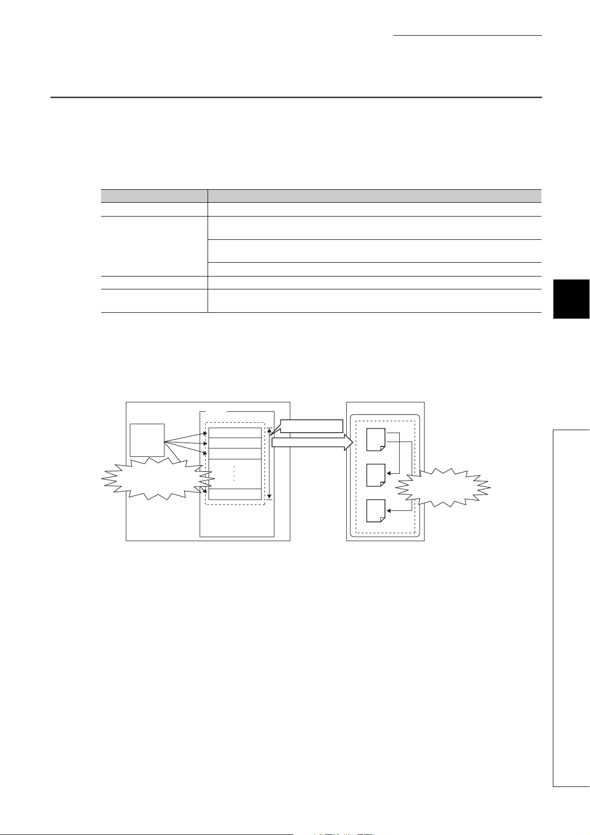
CHAPTER 6 DATA LOGGING FUNCTION
:
18:55:18 67,723,36,0
18:55:19 68,741,36,0
18:55:20 69,712,36,1
18:55:20 70,724,36,1
18:55:20 71,732,36,1
18:55:20 72,733,
18:55:16 65,725,36,1
18:55:17 66,756,36,0
:
18:55:18 67,723,36,0
18:55:19 68,741,36,0
18:55:20 69,712,36,1
18:55:20 70,724,36,1
18:55:20 71,732,36,1
18:55:20 72,733,
18:55:16 65,725,36,1
18:55:17 66,756,36,0
:
18:55:18 67,723,36,0
18:55:19 68,741,36,0
18:55:20 69,712,36,1
18:55:20 70,724,36,1
18:55:20 71,732,36,1
18:55:20 72,733,
18:55:16 65,725,36,1
18:55:17 66,756,36,0
Stack file
Saved file
Saved file
1st sampling data
2nd sampling data
Device
area
Buffer
SD memory card
Specified
device data
sampling
CPU module
Buffer capacity for setting 1
3rd sampling data
nth sampling data
(a) Missing caused by short
sampling interval or too
many data to be sampled
(b) Missing caused by
frequent file switching
6.7 Data Missing
When some of the data to be sampled is not obtained and data are not successively collected, this state is called
missing.
(1) Cases of data missing
Data missing occurs in the following cases.
Item Description
Processing overflow Processing overflow occurs at the specified sampling interval or timing.
When "Auto Start" is set in the Operation at transition to RUN setting, the CPU module is set to RUN,
STOP, and RUN again.
CPU module operation
Operation by the special relay The special relay (Data logging start) is turned off and on.
Operation by the configuration
tool
When "Auto Start" is set in the Operation at transition to RUN setting, the CPU module is powered off and
on.
When "Auto Start" is set in the Operation at transition to RUN setting, the CPU module is reset.
After sampling pauses by the operation from the configuration tool, a start operation is performed.
6
(2) Missing due to processing overflow
If data sampling is performed at short intervals and processing is not completed within the interval, data writing
from devices to the buffer is not possible,
resulting in missing of sampled data. The following two factors cause processing to overflow.
(a) "The data sampling interval is too short." or "Too many data are to be sampled."
If the speed of saving data in the buffer exceeds that of saving data to the SD memory card, the buffer will be
full of sampled but non-overwritten data (that are not yet saved to the SD memory card). Because data cannot
be written from the device area to the buffer, data will be missed.
6.7 Data Missing
(b) File switching occurs frequently.
During file switching, data are not saved from the buffer to the SD memory card. If file switching occurs
frequently, the buffer will be full of sampled but non-overwritten data (that are not yet saved to the SD memory
card). Because data cannot be written from the device area to the buffer, data missing will occur.
(c) When the data logging file transfer function is used
During file transfer by the data logging file transfer function, data are not saved from the buffer to the SD
memory card. Therefore, the buffer will be full of sampled but non-overwritten data (that are not yet saved to
the SD memory card) soon, compared when the data logging file transfer function is not used. Because data
cannot be written from the device area to the buffer, data will be missed.
69

(d) When other functions are used
When the following functions are used, the data sampling performance of data logging is deteriorated.
• Project data batch save/load function (applicable to the LCPU only)
• iQ Sensor Solution data backup/restoration function
Therefore, data missing may occur even with the data logging settings with which it did not occur previously.
Also, with a setting with which data missing occurred previously, the frequency of data missing may increase.
● Once missing occurs, it tends to recur afterward. The following settings can reduce frequency of missing.
• Increase the sampling interval. ( Page 115, Section 8.4.4)
• Decrease the number of sampled data. ( Page 117, Section 8.4.5)
• Increase the buffer capacity. ( Page 135, Section 8.5.2)
• Decrease frequency of file switching. ( Page 127, Section 8.4.12)
• Cancel the "File Transfer" setting in the data logging setting. ( Page 129, Section 8.4.13)
To consider the processing time taken to data logging, refer to Page 161, CHAPTER 10.
● When sampling cannot be completed within the specified sampling interval due to execution of an instruction of which
processing time is long (such as the FMOV instruction), it is not regarded as data missing.
70

CHAPTER 6 DATA LOGGING FUNCTION
6.8 SD Memory Card Life When the Data Logging Function
is Used
Each SD memory card has its limit on writing data. This section describes how to calculate the life of an SD memory
card when the data logging function is used. Use the calculated limit for reference since the actual life of the card
varies depending on the use conditions and environment.
(1) Calculation formula
SD memory card life (year) = Total size of data that can be written (G bytes) Size of data to be written per year
(G bytes/year)
(2) Total size of data that can be written
Capacity Number of writes
*1 For the capacity of applicable SD memory cards and the number of writes, refer to the following.
User's Manual (Hardware Design, Maintenance and Inspection) for the CPU module used
6
(3) Size of data to be written per year
The size of data to be written per year is obtained by the following formula.
*1
Size of data to be written per year (G bytes/year) = ((DS1
*1
(DCS1
*1 Round up DSn and DCSn to a multiple of 512.
DSn, DNn, DCSn, and DCNn are obtained as follows:
+ 6144) DCN1 + + (DCSn*1 + 6144) DCNn) 1073741824
(a) Data logging data size per record (DSn)
CSV file output format: Refer to (5) in the following section. ( Page 37, Section 3.3.2)
(b) Number of records for data logging per year (DNn)
• Continuous logging: DNn = 60 60 24 365 Collection interval and timing (seconds)*1 Operating
*2
rate
• Trigger logging: DNn = Total number of records
• Specification period logging: DNn = 60 60 24 365 Collection interval and timing (seconds)*1
Specification period logging operating rate
*1 A value that is determined depending on the condition set in "Sampling" when "Continuous logging" is selected for the
logging type. (When the value is determined in milliseconds, convert the value into seconds.)
*2 Calculate the ratio according to the operating time of the CPU module per year. For example, if the operating time per
year is 5000 hours, the operating rate is 0.57 (5000 (24 365)).
*3 A value set in "No. of records" when "Trigger logging" is selected for the logging type
*4 Calculate the operating rate according to the total time during which the conditions of the specification period are met on
the CPU module per year. For example, if the total time of the specification period per year is 2500 hours, the operating
rate is 0.28 (2500 (24 365)).
*4
+ 6144) DN1 + + (DSn*1 + 6144) DNn +
*3
6.8 SD Memory Card Life When the Data Logging Function is Used
(c) Header size of data logging (DCSn)
CSV file output format: Refer to "File information line" to "Data name line" in the following section. ( Page
37, Section 3.3.2)
71

(d) Number of data logging file switching times per year (DCNn)
Calculate this number with an estimated number according to the save setting of the data logging and system
operations. For example, when 1000 records are set in "Nnumber of records" of "File switching timing" in the
save setting and "Each scanning cycle" is specified for "Sampling interval" in the sampling setting, the time
interval of the file switching is obtained by multiplying the scan time by 1000. For this reason, the number of
data logging file switching times per year is obtained by the following formula: 60 60 24 365 (Scan time
(second) 1000).
72

CHAPTER 6 DATA LOGGING FUNCTION
6.9 Precautions to Take When Using the Data Logging
Function
This section describes precautions for using the data logging function.
(1) Exclusive processing
(a) Sampling trace during data logging execution
Sampling trace is not executable during data logging execution.
(b) Data logging during sampling trace execution
Sampling trace continues normally, and an error is detected in data logging.
(c) Online change during data logging execution
When a value is specified for "Step No." in "Sampling" or "Trigger", online change continues normally, and an
error is detected in data logging.
6
(d) Data logging during online change execution
When a value is specified for "Step No." in "Sampling" or "Trigger", online change continues normally, and an
error is detected in data logging.
(e) CPU module change by using an SD memory card during data logging execution
CPU module change by using an SD memory card is not executable during data logging execution.
(f) Data logging during execution of CPU module change by an SD memory card
CPU module change by using an SD memory card continues normally, and an error is detected in data logging.
(g) Concurrent execution of data logging and real-time monitor
If the sum of the total buffer capacity used in the data logging function and the total buffer capacity used in the
real-time monitor function exceeds 5120K bytes, the function that has been executed at a later time results in
an error. When executing these functions concurrently, adjust the sum of the buffer capacity used in each
function to not more than 5120K bytes.
(h) PLC memory formatting during data logging execution
While sampled data are being saved from the buffer to an SD memory card, PLC memory formatting cannot be
performed to the memory where the setting file of the currently executing data logging is stored.
(i) Data logging during execution of PLC memory formatting
PLC memory formatting continues normally, and an error is detected in data logging.
6.9 Precautions to Take When Using the Data Logging Function
(2) Multiple trigger logging settings
In multiple trigger logging settings, the following causes an error at start of data logging.
• Specifying a device in "Condition specification" of "Trigger".
73

(3) Holding and clearing the data logging setting
The data logging setting registered to the CPU module is latched. Even if the CPU module is powered off and on
or is reset, the data logging can be performed again with registered setting data. However, the data logging status
is cleared when the storage destination is an SD memory card and any of the following conditions is met. Write
the setting data again.
• The CPU module is powered off and on or is reset with the SD memory card removed.
• When the CPU module change function with SD memory card is used, the CPU module is powered off and
on or is reset with no setting data stored in the SD memory card. (If the SD memory card after replacement
contains setting data, registration is performed with the data.)
(4) Availability of data logging
Data logging can be executed through another station or a serial communication module on the network.
For the same setting number, however, simultaneous execution by multiple routes is not allowed.
(5) Execution of data logging
Once data logging is started, it can be executed only with the memory where the setting file of the currently
executing data logging is stored. (A data logging setting file stored in a different memory cannot be used.)
(6) Start operation after stop of trigger logging
When data logging is restarted after stop or temporary stop of data logging before completing trigger logging,
data are collected from the initial status before the trigger.
(7) When data logging registration failed
If a part of multiple data logging settings fails to be registered, successfully registered data loggings only will be
executed. Note that, however, registration by auto logging is different in operation.
( Page 78, Section 7.2 (2))
(8) Sampling interval setting in "Sampling"
When "Time specification" is set for the sampling interval in "Sampling", sampling is executed as interrupt
processing. Therefore, scan time will be extended and a watchdog timer error may occur in the following cases.
• Short sampling interval and many data logging executions per scan
• Large volume of data to be sampled, and long data logging processing time
(9) Checking the sampling interval
Depending on the accuracy of the clock, some errors may be observed in the information output to the "Date"
column. Check the sampling intervals with the information output to the "Sampling interval" column. For the
accuracy of the clock, refer to the following.
User's Manual (Hardware Design, Maintenance and Inspection) for the CPU module used
(10)When a file register is specified
When a file register is specified in "Device specification" in "Sampling" or "Trigger", do not change the block
numbers and file name of the file register after registration of the data logging. Doing so may disable normal
collection of logging results.
74

CHAPTER 6 DATA LOGGING FUNCTION
Ex.
(11)When "Sampling" is set to "Step No. specification"
With "Sampling" set to "Step No. specification", the processing time of data logging is added to the program
running time. Accordingly, when "Step No. specification" is specified, design watchdog timer settings and
interrupt programs with a consideration of the processing time of data logging (setting the fixed scan interval).
(12)Sampled data being saved to an SD memory card
If the CPU module is powered off or reset while data in the buffer is being saved to an SD memory card, unsaved
data will be cleared. However, data will be saved without being cleared in the following cases.
• Status change from RUN to STOP
• Pause caused by turning off the special relay (Data logging start)
• Stop or pause operation from the configuration tool
• Execution of the trigger logging reset instruction (LOGTRGR)
(13)Changing clock data
Do not change clock data of the CPU module during execution of data logging. Doing so will cause incorrect
"Date" column information to be output to the CSV file. (Even if clock data are changed, data are collected at the
specified intervals or timing. Therefore, changed clock data will be output in the Date column of the CSV file.)
6
(14)Sampling timing when the display unit is attached
An error of up to 100s may occur in the sampling timing when the display unit is attached.
A time value is set for "Time specification" of "Sampling", without setting of data sampling at the END
processing.
(15)Removing the SD memory card
When data logging is being executed with the data logging setting stored in an SD memory card, the
corresponding bit of SD604 (Memory card use conditions) turns on.
Because of this, the following LEDs do not turn off when the removal operation is performed.
• SD CARD LED of the High-speed Universal model QCPU and Universal model Process CPU: when the SD
memory card access control switch is pressed for 1 second or longer
• SD LED of the LCPU: when the SD memory card access control switch is slid up
To remove the SD memory card in the above case, stop the data logging processing and remove the SD memory
card again. For details on the removal procedure, refer to the following. For details on the removal procedure,
refer to the following.
User's Manual (Hardware Design, Maintenance and Inspection) for the CPU module used
(16)Using data that are set by a CPU module of a different series
If the High-speed Universal model QCPU or Universal model Process CPU executes data logging using the
settings stored in an SD memory card by a CPU module of a different series, an error occurs. ( Page 180,
Section 13.1)
Since the LCPU can use the settings stored in an SD memory card by a CPU module of a different series, no
error occurs.
6.9 Precautions to Take When Using the Data Logging Function
75

(17)When the CPU module is locked with a security key
No device comment can be output to the data logging file.
(18)Disabling the addition of character string by the data logging file name
addition instruction when the data logging is registered
When the data logging is registered by writing of data logging setting of the target setting number after the data
logging file name addition instruction (SP.LOGFILES instruction) is executed, addition of a character string
executed by this instruction is disabled. (The bits corresponding to the setting numbers of SD710 to SD712 are
turned off.) Therefore, execute the instruction again when adding a character string. ( Page 177, Section 11.3
(3))
76

CHAPTER 7 OTHER FUNCTIONS
CHAPTER 7 OTHER FUNCTIONS
This chapter describes the functions other than the data logging function.
7.1 Data Logging Operation at Transition to RUN
After registration of a data logging setting, logging operation for the following transition to RUN can be specified.
Setting is available for each of setting No.1 to No.10. ( Page 131, Section 8.4.14)
(1) Relevant operations
The relevant operations are shown below.
• Power-on RUN
• Reset RUN
•STOP RUN
(2) Selectable operations
Select an operation from the following.
• Auto Start
• Start by User Operation
(a) When "Auto Start" is selected
Data logging is automatically started after the operation listed above.
To start the data logging at the first time, the user must perform a specific operation.
(b) When "Start by User Operation" is selected
Data logging is temporarily stopped after the operation listed above. To restart the data logging, the user must
perform a specific operation.
When the auto logging function is enabled, even if "Start by User Operation" is set, the same operation as "Auto Start" is
performed.
7
7.1 Data Logging Operation at Transition to RUN
77

7.2 Auto Logging by Inserting an SD Memory Card
Prepare an SD memory card where the auto logging setting is stored.
Start
Insert the SD memory card into the slot of the running CPU module.
Slide the SD memory card access control switch upward,
stop the card access, and then remove the SD memory card.
End
Data logging automatically starts.
The SD CARD LED or SD LED turns on.
Upon completion of auto logging,
the SD CARD LED or SD LED starts flashing.
Writing auto logging settings to an SD memory card and inserting it into a running CPU module will automatically start
logging. All of continuous logging, trigger logging, and specification period logging are executable. Individual setting is
not available for each of setting No.1 to No.10. ( Page 134, Section 8.5.1)
(1) Procedure to use
The following is the procedure to use the auto logging function.
● A new data logging cannot be started during auto logging operation.
● After completion of auto logging, replace the SD memory card where the auto logging settings are stored. Otherwise,
another auto logging cannot be started.
(2) When data logging registration by the auto logging function failed
When multiple data logging settings are registered by the auto logging function, if a part of them has failed to be
registered, all of data logging will not be executed.
78

CHAPTER 7 OTHER FUNCTIONS
(3) Conditions for auto logging completion
When one of the following conditions is met, the auto logging is terminated. The following conditions can be set in
combination. In that case, the auto logging is terminated when either of the conditions is met first.
Condition Setting
Data logging stop
Time r
(a) When "Data logging stop" is set
The auto logging is terminated when all or any of the configured data loggings is stopped.
Data logging stop is defined as follows:
• Continuous logging: The number of saved files in the Save setting is exceeded, and data logging is
completed.
• Trigger logging: Data of the specified number of records have been collected and written to the SD
memory card, and data logging is completed.
• Specification period logging: The number of saved files in the Save setting is exceeded, and data logging
is completed.
• Data logging is stopped from the configuration tool.
Select one from the following.
• When all data loggings stop
• When any of the data loggings stops
Select "Complete with timer".
Setting range for "Elapsed time": 1 to 86400 seconds (in increments of 1s)
7
● When continuous logging or specification period logging is selected for a data logging for which auto logging is enabled,
if "Overwrite" is selected in the "Number of saved files" setting, the data logging will not be terminated. Therefore, select
"Stop".
● If "When any of the data loggings stops" is selected, operation of a data logging in execution, which is other than the
stopped one, is the same as the operation performed after the time specified with the timer has elapsed.
(b) When "Timer" is set
After start of data logging execution, when operating time reaches the specified time, all of the data collected
until then are saved on the SD memory card, and the auto logging is completed. However, for trigger logging, if
data of the specified number of records have not been collected yet, the data including collected data will not
be saved.
If a data logging is temporarily stopped before completion of auto logging and then restarted, the timer is cleared to zero.
However, when a temporary stop is caused by turning off the special relay (Data logging start), the timer continues running
even while the data logging is temporarily stopped.
7.2 Auto Logging by Inserting an SD Memory Card
79

(4) Conditions for auto logging inactivation
After completion of auto logging, the following operation does not start another auto logging.
• Power off on
• Reset
•STOP RUN
Also, auto logging does not start even if the following operation is performed with an SD memory card (with the
auto logging setting) inserted.
• Power off on
• Reset
(5) Operation when the status is changed to RUN
When the auto logging function is enabled for multiple data logging settings, if the following is performed with a
part of data logging completed and then the status is changed to RUN, unfinished data loggings only will be
started.
• Power off on
• Reset
(6) When an error occurs
When an auto logging error occurs, the operation is as follows:
(a) Registration failure at start of auto logging
When auto logging was not executed due to registration failure at the start of auto logging, the operation will be
the same as the one performed upon completion of auto logging.
(b) Error occurred during auto logging execution
Even if an error occurs during auto logging execution and the data logging is stopped, it can be restarted by
turning on the special relay (Data logging start). Because of this, the error is not included in the conditions for
auto logging completion. However, when online change is performed during auto logging execution, the data
logging cannot be restarted although it is also detected as an error. Therefore, this is included in the conditions
for auto logging completion.
*1 Only when "When all data loggings stop" is selected
*1
80

CHAPTER 7 OTHER FUNCTIONS
Remark
7.3 File Access
The FTP server function allows saving and deletion of data logging files from the SD memory card installed in the CPU
module to the personal computer. The following commands can be used for access. When a file is to be specified, use
a command for which a folder name can be included. Available commands are shown below.
Command Function Command Function
delete Deletes a file. mdir Stores file information in a file.
mdelete Deletes files. ls Displays a file name.
get Reads a file. mls Stores a file name in a file.
mget Reads files. rename Changes a file name.
dir Displays file information. quote change Displays or changes a file attribute.
For details on command specification, refer to the following.
QnUCPU User's Manual (Communication via Built-in Ethernet Port)
MELSEC-L CPU Module User's Manual (Built-In Ethernet Function)
7
7.3 File Access
81

7.4 Data Logging File Transfer Function
Remark
Before using the function with the LCPU, check the versions of the CPU module and configuration tool used. ( Page
190, Appendix 2)
This function supports the client function of the FTP (File Transfer Protocol), a protocol for file transfer with external
devices. By using the data logging file transfer function, the CPU module serves as an FTP client, and data logging
files in SD memory cards can be transferred to the FTP server. Since data logging files can be managed by one FTP
server, data management and maintenance work can be reduced.
FTP server
QnUDVCPU
LOG01_
00000026
.csv
Data logging
file
SD memory card
Ethernet
LOG01_
00000001
.csv
QnUDVCPU
LOG02_
00000026
.csv
Data logging
file
SD memory card
LOG02_
00000001
.csv
LOG03_
00000001
.csv
LCPU
LOG03_
00000026
.csv
Data logging
file
SD memory card
82
The data logging file transfer function requires an FTP server. For details on the server, refer to the manual for the server
used.

CHAPTER 7 OTHER FUNCTIONS
7.4.1 Procedure overview of the data logging file transfer function
The following flowchart lists a procedure for performing the data logging file transfer function.
<Preparation for data logging>
Configure data logging settings and write
them to the CPU module (standard
ROM/SD memory card).
<Start of data logging>
Start data logging by the start operation
from the configuration tool.
<Start of data logging file transfer function>
The data logging file transfer function starts
when data logging starts.
<Data sampling>
The data configured in the configuration tool
are collected and saved to an SD memory
card.
*4
transfer set?
<Stop of data logging>
By the following operation, registration of
the data logging setting in the CPU module
is cancelled.
• Stop operation from the configuration tool
<Stop of data logging file transfer function>
The data logging file transfer function stops
when the file transfer is completed.
Is the file
No
Yes
<File transfer>
Data logging files are transferred to the FTP
server.
• Standby : When a file is saved while other
files are being transferred, the
file enters standby.
• Transfer data overflow : A standby file
enters the transfer data overflow
status when a file with the same
setting No. as that of the standby
file is saved.
*1
*3
*2
Has
the file transfer
completed?
Yes
7
7.4 Data Logging File Transfer Function
*3
No
If a file transfer has failed
due to communication error,
files are resent (retry).
*3
7.4.1 Procedure overview of the data logging file transfer function
: User operation
: Operation of CPU module
*1 Check that the CPU module is connected to the target server using a file transfer test before performing file transfer.
( Page 88, Section 7.4.4)
*2 Transfer status can be checked using file transfer diagnostics. ( Page 89, Section 7.4.5)
*3 For the start operation from the configuration tool, refer to Page 149, Section 8.10.
*4 For the file transfer status, refer to Page 85, Section 7.4.3.
83

7.4.2 Directory structure of the FTP server
LOG01
00000001
18:55:16 65,725,36,1
18:55:17 66,756,36,0
18:55:18 67,723,36,0
18:55:19 68,741,36,0
18:55:20 69,712,36,1
18:55:20 70,724,36,1
18:55:20 71,732,36,1
18:55:20 72,733,
00000001.CSV
18:55:16 65,725,36,1
18:55:17 66,756,36,0
18:55:18 67,723,36,0
18:55:19 68,741,36,0
18:55:20 69,712,36,1
18:55:20 70,724,36,1
18:55:20 71,732,36,1
18:55:20 72,733,
00000002.CSV
18:55:16 65,725,36,1
18:55:17 66,756,36,0
18:55:18 67,723,36,0
18:55:19 68,741,36,0
18:55:20 69,712,36,1
18:55:20 70,724,36,1
18:55:20 71,732,36,1
18:55:20 72,733,
00000100.CSV
/
File storage
folder
18:55:16 65,725,36,1
18:55:17 66,756,36,0
18:55:18 67,723,36,0
18:55:19 68,741,36,0
18:55:20 69,712,36,1
18:55:20 70,724,36,1
18:55:20 71,732,36,1
18:55:20 72,733,
00000101.CSV
18:55:16 65,725,36,1
18:55:17 66,756,36,0
18:55:18 67,723,36,0
18:55:19 68,741,36,0
18:55:20 69,712,36,1
18:55:20 70,724,36,1
18:55:20 71,732,36,1
18:55:20 72,733,
00000102.CSV
00000101
When data logging files are transferred, a folder is automatically created in the specified directory path on the FTP
server, and the data logging files are saved in the folder.
When files are simultaneously transferred from different CPU modules to one FTP server, they may overwrite each other.
Specify a different directory path as a storage location of each file.
84

7.4.3 File transfer status
Ex.
Data logging setting
Data logging
start request
SM1940
(Data logging preparation)
SM1941
(Data logging start)
SM1948
(Data logging file transfer
execution status flag)
Start of data logging file transfer function
ON
OFF
ON
OFF
ON
OFF
There are five file transfer status levels:
• Transfer start
• Standby
• Transfer data overflow
•Retry
• Transfer completion (stop)
(1) Transfer start
Data logging files of each setting No. are transferred one by one. Data logging file transfer starts simultaneously
with the data logging start operation, and the special relay (Data logging file transfer execution status flag) turns
on.
CHAPTER 7 OTHER FUNCTIONS
(2) Standby
When a data logging file is newly saved during data logging file transfer, the new file enters standby. Only one
data logging file enters standby in each setting No. If a data logging file with the same setting No. as the standby
file is saved, the standby file enters transfer data overflow status. ( Page 86, Section 7.4.3 (3))
After completion of the ongoing transfer processing, a standby data logging file is started to be transferred. When
there are several standby data logging files, they are transferred in the order that they are saved in the SD
memory card.
When a data logging file of setting No.4 is saved while data logging files are on standby in the order of
setting No.2 and setting No.3
Data logging
setting No.4
Data logging file
Standby
Data logging
setting No.3
Data logging file
Data logging
setting No.2
Data logging file
Transfer
completed
7.4.3 File transfer status
7
7.4 Data Logging File Transfer Function
A newly saved data
logging file is on
standby.
Transferred in
an orderly manner
FirstLast
The first saved
data logging file on
standby starts to
be transferred.
85

(3) Transfer data overflow
Ex.
If a data logging file with the same setting No. as a standby file is saved, the standby file will not be transferred.
When a data logging file of setting No.2 is saved while a data logging file of setting No.2 is on standby
Standby
Transfer
completed
Data logging
setting No.2
Data logging file
A data logging file
with the same
setting No. as that
of the standby file
is saved.
Data logging
setting No.3
Data logging file
Transferred in
an orderly manner
Data logging
setting No.2
Data logging file
The standby data logging
file enters the transfer
data overflow status.
FirstLast
Data logging
setting No.1
Data logging file
If transfer data overflow frequently occurs, the frequency can be reduced by taking the following actions:
• Increase the sampling interval. ( Page 115, Section 8.4.4)
• Decrease the number of sampled data. ( Page 117, Section 8.4.5)
• Decrease frequency of file switching. ( Page 127, Section 8.4.12)
If transfer data overflow still frequently occurs even after the above actions are taken, settings (e.g. "Save" and "Sampling"
settings) configured for other data logging setting Nos. should be changed. Correct settings for other data logging setting
Nos. of files during transfer processing.
86

CHAPTER 7 OTHER FUNCTIONS
Data logging file
Transferred in
an orderly
manner
A data logging file that failed to
be transferred enters standby to
be resent.
Standby
Data logging file
Data logging
setting No.3
Data logging file
Data logging
setting No.2
FirstLast
Transfer
failed
Data logging
setting No.1
A communication
error occurs.
Transfer failed due
to errors such as
network failure.
Data logging
stop request
Buffer data
saved
SM1940
(Data logging preparation)
SM1941
(Data logging start)
SM1948
(Data logging file transfer
execution status flag)
The data logging file transfer function stops.
ON
OFF
ON
OFF
ON
OFF
File transfer completed
Buffer data
being saved
File being
transferred
(4) Retry
If data logging file transfer failed due to network failure between the CPU module and the FTP server, the data
logging file not yet transferred is repeatedly sent until the network returns to normal.
The retry processing ends when the network returns to normal and file transfer is completed. However, even if file
transfer fails, the processing ends when any of the following conditions is met:
• Retransmission of data logging files failed due to an error other than communication error
• Retransmission failed after the elapse of the retry time
• The file enters transfer data overflow status.
• File transfer is stopped during retry by forced stop. ( Page 91, Section 7.4.6 (6))
*1
7
(5) Transfer completion (stop)
*1 Refers to the time from retry start to file retransmission. ( Page 129, Section 8.4.13)
Only the latest data logging file is retransferred when network returns to normal. When retransmitting the untransferred file
before the network returns to normal, use stack logging file transfer. ( Page 92, Section 7.4.7)
Files enter transfer completion status when the data logging stop operation is performed and all data logging files
with the same setting No. have been transferred. When file transfer is completed, the special relay (Data logging
file transfer execution status flag) turns off.
87
7.4.3 File transfer status
7.4 Data Logging File Transfer Function

7.4.4 File transfer test
Communication status and settings between the CPU module and the FTP server can be checked by transferring a
test file from the CPU module to the FTP server. Since this function can be executed without starting or stopping data
logging, file transfer operation can be checked before system operation.
(1) Procedure
The following describes a procedure for file transfer test.
1. Configure destination server settings using configuration tool. ( Page 129, Section 8.4.13)
2. Click the button in the "FTP Setting" window to execute a file transfer test.
[Data logging Setting] [File Transfer] [Server Setting]
3. Check the test result in the displayed window.
4. Check if the test file has been transferred in the directory path on the FTP server.
(2) Test file structure
The following describes a test file structure to be transferred to the FTP server.
(a) Test file name
MELSEC_CPU_FTP_TEST_data logging setting No..txt
A test file of setting No.1 has the following file name:
MELSEC_CPU_FTP_TEST_01.txt
(b) Information in a test file
A test file contains the IP address of the CPU module, date and time when the test is executed.
Ex.
192.168.10.39_20101001_170230
TimeIP address Date
● Even if a file transfer test failed due to a communication error, file transfer will not be performed again.
● A file transfer test cannot be simultaneously executed from multiple configuration tools. Execute a file transfer test after
the ongoing test is ended.
● In a file transfer test, "FTP Server Connection Request Timeout Time" is fixed to 10 seconds.
88

7.4.5 File transfer diagnostics
This function stores file transfer status of the data logging file transfer function.
(1) File transfer status
The transfer status can be checked in the "Data Logging File Transfer Status" window. ( Page 154, Section
8.12)
[Online] [Data Logging File Transfer Status]
The following lists the transfer status:
•"": "File transfer" in the data logging setting is not set.
• "Stopped": The data logging file transfer function is stopped.
• "Retrying": The data logging file transfer function is being retried.
• "Transferring": A file is being transferred by the data logging file transfer function.
• "Waiting for transfer": A file is on standby for transfer.
CHAPTER 7 OTHER FUNCTIONS
*1
When the data logging file transfer function is used
*1 Even if data logging status is "Completed" or "Pausing", file transfer status is in "Waiting for transfer".
If the CPU module is powered off and on or is reset during file transfer, data logging files not yet transferred will not be
transferred.
(2) File transfer error log
Error logs can be checked in the "File Transfer Error Log" window. ( Page 154, Section 8.12)
[Online] [Data Logging File Transfer Status] button
Up to 30 error logs can be stored. (If errors are collected more than 30, an error log is deleted from the oldest
one.) Error logs are held when the CPU module is powered off and on or is reset.
7
7.4 Data Logging File Transfer Function
7.4.5 File transfer diagnostics
89

7.4.6 Precautions for using the data logging file transfer function
This section describes precautions for using the data logging file transfer function.
(1) Concurrent execution of another function
(a) Auto logging function
The data logging file transfer function cannot be performed during auto logging.
(b) Functions of a programming tool
If either of the following functions is executed from a programming tool during data logging file transfer, an error
may occur. An error also may occur in a standby data logging file and a data logging file during retry
processing.
• SD memory card formatting
• CPU module change function with SD memory card
(2) Sampling performance
When the data logging file transfer function is used, the sampling performance is degraded, compared when the
function is not used. Therefore, data missing may occur even if it did not occur when the data logging file transfer
function was not used. If data missing had occurred before the function is used, the frequency of data missing
may rise. ( Page 69, Section 6.7)
(3) IP address setting for Ethernet communication
In the data logging file transfer function, data logging files are transferred to the FTP server through built-in
Ethernet ports of the CPU module. Set "IP Address" in the "Built-in Ethernet Port Setting" tab using a
programming tool.
QnUCPU User's Manual (Communication via Built-in Ethernet Port)
MELSEC-L CPU Module User's Manual (Built-In Ethernet Function)
(4) Port numbers when the socket communication function is used
For the data logging file transfer function, own station port numbers, F000H to FFFEH, are used for FTP
communication. Do not specify F000
communication function (SP.SOCOPEN) during execution of the data logging file transfer function.
QnUCPU User's Manual (Communication via Built-in Ethernet Port)
MELSEC-L CPU Module User's Manual (Built-In Ethernet Function)
to FFFEH using the connection establishment instruction for the socket
H
(5) Processing time of file transfer
Time taken to file transfer depends on a load placed on the Ethernet line (congestion of the line), operating status
of other communication functions, and system configuration.
90

CHAPTER 7 OTHER FUNCTIONS
(6) Starting data logging during file transfer
Another data logging cannot be started to the same file being transferred. If the start operation is performed, the
following window appears. Select whether to start the data logging or not.
Clicking "Yes" will stop transferring data logging files. (Files not yet completely transferred may remain on the
FTP server. Standby data logging files (including files during retry processing) will no longer be on standby, and
an error will occur.)
(7) Data logging file that results in a file transfer error
If an error caused by communication error, file access error, or file transfer stop error occurs during file transfer,
data logging files not yet completely transferred may remain on the FTP server. Since unreliable, the logging files
should not be referred to (Data logging files in file transfer error can be checked in the "File Transfer Error Log"
window).
(8) Latch clear during data logging file transfer
If latch clear is executed during data logging file transfer, data logging status will be unregistered. The operation
will be in the same status when the data logging stop operation is performed.
(9) Powering off and on or resetting the CPU module during data logging file
transfer
If the CPU module is powered off and on or is reset during data logging file transfer, data logging files not yet
completely transferred may remain on the FTP server. Note that transfer of a standby data logging file (including
a file that were in retry process) and a data logging file that was being transferred will not be resumed.
7.4.6 Precautions for using the data logging file transfer function
7
7.4 Data Logging File Transfer Function
91

7.4.7 Stack logging file transfer
Remark
<Stored files>
00000001.CSV (transferred file)
00000002.CSV (transferred file)
00000003.CSV (transferred file)
00000004.CSV (transferred file)
00000005.CSV (transferred file)
00000006.CSV (untransferred file)
00000007.CSV (untransferred file)
00000008.CSV (untransferred file)
Data logging files that have
not been transferred to the
FTP server due to the network
disconnection.
Execution of the
data logging function
Ethernet Hub
FTP server
Network
disconnected
<Stored files>
00000001.CSV
00000002.CSV
00000003.CSV
00000004.CSV
00000005.CSV
<Stored files>
00000001.CSV
00000002.CSV
00000003.CSV
00000004.CSV
00000005.CSV
00000006.CSV
00000007.CSV
00000008.CSV
<Stored files>
00000001.CSV (transferred file)
00000002.CSV (transferred file)
00000003.CSV (transferred file)
00000004.CSV (transferred file)
00000005.CSV (transferred file)
00000006.CSV
00000007.CSV
00000008.CSV
Execution of the
data logging function
Ethernet Hub
FTP server
The untransferred
files can be transferred
to the FTP server
when the network
recovered.
untransferred file
Network
recovered
Check the versions of the CPU module and configuration tool used when using this function with the LCPU. ( Page 190,
Appendix 2)
This function cannot be used with the High-speed Universal model QCPU and Universal model Process CPU.
Transfer the untransferred data logging file when switching file due to the network failure by using data logging file
transfer function to the FIP server. The data logging file made during network failure can be transferred when the
network recovered because the order of file transfer is decided.
92

CHAPTER 7 OTHER FUNCTIONS
Ex.
(1) Setting methods
Settings for the stack logging file transfer is set by "File transfer" in data logging settings. ( Page 129, Section
8.4.13)
(2) File transfer
(a) Order
Files are transferred in order from a small number of file names within the data logging setting number.
(b) Timing of transfer
If the next transfer file has already been stored when the file transfer is completed, the next file is transferred
sequentially. If the next file has not yet been stored, the file is transferred when switching file.
When data logging setting No.1 file (00000001.csv) is completed, the next data logging setting No.1 file
(00000002.csv) of has already been stored.
1) Checks whether a next file with
the same setting No. is saved
when the file transfer is
completed.
2) If the next file is already saved,
the file enters standby.
LOG01
Data logging
setting No.1
Data logging file
00000001.CSV
Data logging
setting No.1
Data logging file
00000001.CSV
7
Standby
Data logging
setting No.3
Data logging file
00000001.CSV
Transferred in
an orderly
manner
Data logging
setting No.4
Data logging file
00000001.CSV
FirstLast
Transfer completed
Data logging
setting No.1
Data logging file
00000001.CSV
(3) Retransmission
With the stack logging file transfer, a file is repeatedly sent until the file transfer is completed. When retransmitting
of the file is completed, check the next file and transfer sequentially until all stored files are transferred.
7.4 Data Logging File Transfer Function
7.4.7 Stack logging file transfer
93

7.4.8 Transfer completing/Non-completing file distinction
Remark
Ex.
indication
Check the versions of the CPU module and configuration tool used when using this function with the LCPU. ( Page 190,
Appendix 2)
This function cannot be used with the High-speed Universal model QCPU and Universal model Process CPU.
For the data logging file in the SD memory card, character string "C_" (abbreviated designation of "Complete_") is
added to a file name after file transfer completion to the FTP server. Only checking the file name of the data logging file
in the SD memory card can distinguish at first sight whether the file has been transferred to the FTP server.
File name before the transfer: LOG01_00000001.CSV
File name after the transfer: C_LOG01_00000001.CSV
Only a saved file of the data logging function is a target of the character string "C_" addition.
(1) Setting methods
Settings for the stack logging file transfer is set by "File transfer" in data logging settings.
( Page 129, Section 8.4.13)
(2) Cautions
• The saved file name can be set up to 46 characters (including the extension and period) to add the character
string for two characters to the file name by the transfer completion/non-completion file distinction indication.
• When an abnormal completion is encountered as a result of an error during file transfer, character string
"C_" is not added to it.
94

CHAPTER 8 HOW TO USE THE CONFIGURATION TOOL
Start
Configure the auto logging settings.
Enable auto logging?
Configure the auto logging settings.
Yes
No
Is data logging stopped?
Stop the data logging.
Yes
No
Write the settings.
CHAPTER 8 HOW TO USE THE CONFIGURATION
TOOL
This chapter describes the setting procedure and operations for data logging.
8.1 Setting Flow Chart
Follow the flow chart below to configure the settings.
Configure the settings required for data
logging.
( Page 110, Section 8.4)
Start the data logging.
Stop the data logging.
Read the data logging file from the
SD memory card.
8
( Page 134, Section 8.5.1)
8.1 Setting Flow Chart
Before writing common settings, all the data
logging must be stopped.
( Page 145, Section 8.8)
( Page 145, Section 8.8)
Execute or stop the data logging.
( Page 149, Section 8.10)
( Page 152, Section 8.11)
Check the CSV file.
End
95

8.2 Window Structure
This section describes the window structure of the configuration tool.
8.2.1 Main window
The main window of the configuration tool is as shown below.
(1) Displayed window
(2) Displayed items
Name Description Reference
Menu Menu items used for executing respective functions are displayed. Page 97, Section 8.2.2
Toolbar Tool buttons used for executing respective functions are displayed. Page 98, Section 8.2.3
Edit item tree When an item on the tree is selected, the corresponding advanced settings area is displayed. Page 99, Section 8.2.4
Comment
Status bar Information on the current project is displayed. Page 100, Section 8.2.5
Advanced settings area A setting area for each function is displayed.
A comment about the project can be entered. This comment is not written to the CPU module. Up to
1024 one-byte characters (512 two-byte characters) can be entered.
96
CHAPTER 8 HOW TO USE THE CONFIGURATION TOOL
8.2.2 Menu structure
The menu structure of the configuration tool is as listed below.
Project Reference
New Creates a new project, discarding the currently editing project. Page 103, Section 8.3.1
Open Opens a project file that is stored in the local disk. Page 103, Section 8.3.2
Save Saves the current project data to the current file.
Save as Saves the current project file with a different name.
Change PLC series Changes the programmable controller series of the project being edited. Page 105, Section 8.3.4
Read Logging Setting from Memory Card
(SD)
Write Logging Setting into Memory Card
(SD)
Recent Files Lists the recently used files in the configuration tool.
Exit Terminates the configuration tool.
Delete Data Logging Setting Deletes the data logging setting selected on the edit item tree.
Batch Data Insertion Sets the setting items all at once.
Cut Setting Item Cuts the setting in the tabular form.
Paste Setting Item Pastes the setting in the tabular form.
Paste device copied in other application
software
Insert Copied Setting Item Pastes the copied setting in the tabular form. Page 101, Section 8.2.6
Insert device copied in other application
software
Insert Cut Setting Item Pastes the cut setting in the tabular form.
Delete Setting Item Deletes the setting in the tabular form.
Move Setting Item Upward Moves the setting item upward.
Move Setting Item Downward Moves the setting item downward.
Device Batch Replacement Replaces all of the configured devices. Page 102, Section 8.2.7
Switch Display Language Changes the display language from the menu bar. Page 47, Section 5.4
Transfer Setup Performs communication setting for connection to a CPU module. Page 136, Section 8.6
Read Logging Setting Reads the setting from the CPU module. Page 143, Section 8.7
Write Logging Setting Writes the setting to the CPU module. Page 145, Section 8.8
Delete Logging Setting Deletes the setting in the CPU module. Page 145, Section 8.8
Logging Status and Operation Checks the logging status. Page 147, Section 8.9
Logging File Operation
Data Logging File Transfer Status Displays transfer status of data logging files. Page 154, Section 8.12
Reads the data logging setting written on an SD memory card in the personal
computer.
Writes the currently editing data in a form available for CPU module operation. Data
are written directly to the SD memory card in the personal computer. When the SD
memory card is installed into the CPU module, logging is started.
Edit Reference
Pastes a device which is copied in other application into a line selected. (Existing
data in the line are overwritten and erased.)
Pastes a device which is copied in other application into a line selected and shifts
down existing data in the selected line and below.
View Reference
Online Reference
Accesses the CPU module, and downloads or deletes a file in the SD memory card
installed in the CPU module.
Page 104, Section 8.3.3
Page 106, Section 8.3.5
Page 108, Section 8.3.6
Page 99, Section 8.2.4Copy and Add Data Logging Setting Copies the data logging setting selected on the edit item tree and adds it.
Page 101, Section 8.2.6Copy Setting Item Copies the setting in the tabular form.
Page 119, Section 8.4.6
Page 119, Section 8.4.6
Page 101, Section 8.2.6
Page 149, Section 8.10
8.2.2 Menu structure
8
8.2 Window Structure
Tool Reference
Start GX LogViewer Starts GX LogViewer. Page 47, Section 5.3
Help Reference
Open Manual Starts e-Manual Viewer, and opens the manual.
About Configuration tool Displays the product information of the configuration tool.
Page 156, Section
8.13.1
Page 156, Section
8.13.2
97

8.2.3 Toolbar structure
The toolbar structure of the configuration tool is as listed below.
Icon Equivalent menu item Reference
[Project] [New] Page 103, Section 8.3.1
[Project] [Open] Page 103, Section 8.3.2
[Project] [Save] Page 104, Section 8.3.3
[Edit] [Delete Data Logging Setting] Page 99, Section 8.2.4
[Edit] [Cut Setting Item]
[Edit] [Paste Setting Item]
[Online] [Write Logging Setting] Page 145, Section 8.8
[Online] [Read Logging Setting] Page 143, Section 8.7
Page 101, Section 8.2.6[Edit] [Copy Setting Item]
[Online] [Logging Status and Operation] Page 149, Section 8.10
[Online] [Logging File Operation] Page 152, Section 8.11
98
 Loading...