

Page 1

CITY MULTI® H2I® Y-SERIES HYPER-HEATING INVERTER
SYSTEM DESIGN
1. ELECTRICAL WORK ...........................................................................................................................................H2iSD-2
1-1. General Cautions ....................................................................................................................................... H2iSD-2
1-2. Power Supply for Indoor Unit and Outdoor Unit ......................................................................................... H2iSD-3
2. M-NET CONTROL................................................................................................................................................H2iSD-6
2-1. Transmission Cable Length Limitation .......................................................................................................H2iSD-6
2-2. TransmissionCableSpecications ............................................................................................................H2iSD-7
2-3. SystemCongurationRestrictions ............................................................................................................. H2iSD-8
2-4. Address Setting .........................................................................................................................................H2iSD-11
3. PIPING DESIGN ................................................................................................................................................ H2iSD-22
3-1. R410A Piping Material ..............................................................................................................................H2iSD-22
3-2. PUHY-HP-T/Y(S)JMU’s Piping Design ..................................................................................................... H2iSD-23
3-3. Refrigerant Charge Calculation ................................................................................................................ H2iSD-25
4. INSTALLATION ..................................................................................................................................................H2iSD-26
4-1. Installation Site Requirements ................................................................................................................. H2iSD-26
4-2. Installation Clearance Space ................................................................................................................... H2iSD-27
4-3. Piping Direction ........................................................................................................................................ H2iSD-29
4-4. Weather Countermeasures ...................................................................................................................... H2iSD-34
4-5. Low Ambient Kit Application Guidelines ...................................................................................................H2iSD-35
5. STANDARD AND SEACOAST PROTECTION (-BS) TREATMENT ..................................................................H2iSD-37
5-1. H2i Y-Series .............................................................................................................................................H2iSD-37
6. CAUTIONS ......................................................................................................................................................... H2iSD-38
6-1. Refrigerant Properties .............................................................................................................................. H2iSD-38
6-2. ConrmtheCriticalConcentrationandPerformCountermeasures ......................................................... H2iSD-38
SYSTEM DESIGN
Y-SERIES
2010 H2i
®
2010 Hyper-heating Y-SERIES SYSTEM DESIGN (Sept. 2010)
H2iSD-1
Page 2

®
Y-SERIES
2010 H2i
SYSTEM DESIGN
1. ELECTRICAL WORK
1-1. General Cautions
Follow ordinance of your governmental organization for technical standard related to electrical equipment, wiring
regulations, and guidance of each electric power company.
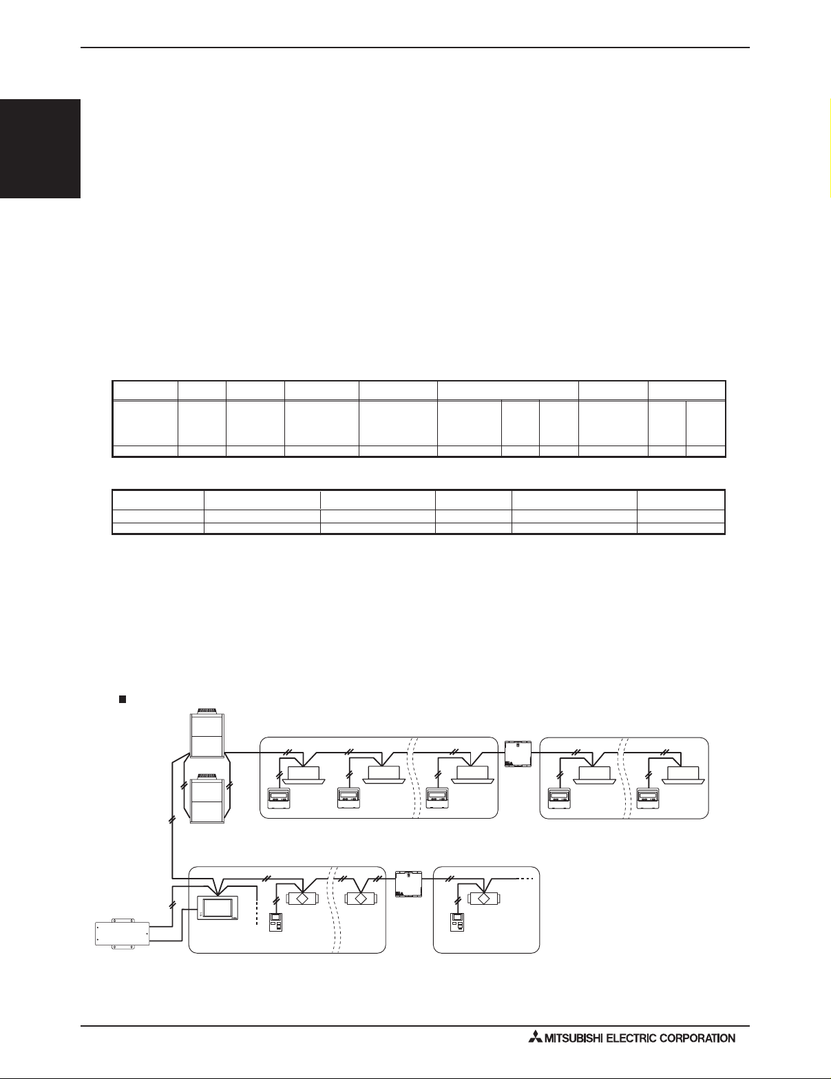
Wiring for control (hereinafter referred to as transmission ) shall be (50mm[1-5/8in] or more) apart from power source
wiring so that it is not influenced by electric noise from power source wiring. (Do not insert transmission and power
source wire in the same conduit.)
Be sure to provide designated grounding work to outdoor unit.
Give some allowance to wiring for electrical part box of indoor and outdoor units, because the box is sometimes removed
at the time of service work.
Never connect 100V, 208~230,460V power source to terminal block of transmission . If connected,electrical parts will
be burnt
Use
multiplecore
out.
2-conductor
cable, the resultant poor transmitting and receiving will cause erroneous operations.
shield cable for transmission . If transmission of different systems are wired with the same
cable
cable
cable
cable
cables
Outdoor
unit
2-conductor shield cable
OK NO
Outdoor
unit
2-conductor shield cable
BC controller
Indoor unit
Remote
controller
Indoor unit
Remote
controller
Outdoor
unit
Outdoor
unit
Multiple-
core cable
Remote
controller
BC controller
controller
Indoor unit
Indoor unit
Remote
H2iSD-2
2010 Hyper-heating Y-SERIES SYSTEM DESIGN (Sept. 2010)
Page 3
1. ELECTRICAL WORK
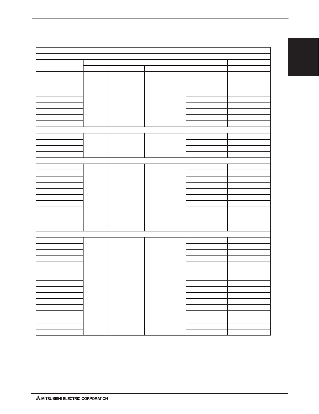
1-2. Power Supply for Indoor and Outdoor Units
1-2-1. Electrical Characteristics of the Indoor Units
Symbols: MCA : Min.Circuit Amps (=1.25xFLA) FLA : Full Load Amps
IFM :Indoor Fan Motor Output : Fan motor rated output
Model
PLFY-P08NCMU-E
PLFY-P12NCMU-E 0.35 / 0.35 0.28 / 0.28
PLFY-P15NCMU-E 0.35 / 0.35 0.28 / 0.28
PLFY-P12NBMU-E 0.64 / 0.64 0.51 / 0.51
PLFY-P15NBMU-E 0.64 / 0.64 0.51 / 0.51
PLFY-P18NBMU-E 0.64 / 0.64 0.51 / 0.51
PLFY-P24NBMU-E 0.64 / 0.64 0.51 / 0.51
PLFY-P30NBMU-E 0.64 / 0.64 0.51 / 0.51
PLFY-P36NBMU-E 1.25 / 1.25 1.00 / 1.00
Hz Volts Voltage range MCA(A) FLA(A)
60Hz 208 / 230V 188 to 253V
Indoor Unit IFM
0.29 / 0.29 0.23 / 0.23
SYSTEM DESIGN
Y-SERIES
2010 H2i
®
PMFY-P06NBMU-E
PMFY-P08NBMU-E 0.25 / 0.25 0.20 / 0.20
PMFY-P12NBMU-E 0.26 / 0.26 0.21 / 0.21
PMFY-P15NBMU-E 0.33 / 0.33 0.26 / 0.26
PEFY-P06NMAU-E
PEFY-P08NMAU-E 1.05 / 1.05 0.84 / 0.84
PEFY-P12NMAU-E 1.21 / 1.21 0.97 / 0.97
PEFY-P15NMAU-E 1.45 / 1.45 1.16 / 1.16
PEFY-P18NMAU-E 1.56 / 1.56 1.25 / 1.25
PEFY-P24NMAU-E 2.25 / 2.25 1.80 / 1.80
PEFY-P27NMAU-E 2.49 / 2.49 1.99 / 1.99
PEFY-P30NMAU-E 2.50 / 2.50 2.00 / 2.00
PEFY-P36NMAU-E 3.33 / 3.33 2.66 / 2.66
PEFY-P48NMAU-E 3.41 / 3.41 2.73 / 2.73
PEFY-P54NMAU-E 3.31 / 3.31 2.65 / 2.65
PEFY-P06NMSU-E
PEFY-P08NMSU-E 0.47 / 0.50 0.41 / 0.39
PEFY-P12NMSU-E 0.68 / 0.74 0.46 / 0.43
PEFY-P15NMSU-E 1.20 / 1.33 0.47 / 0.45
PEFY-P18NMSU-E 1.20 / 1.33 0.64 / 0.60
PEFY-P24NMSU-E 1.57 / 1.73 0.88 / 0.83
PEFY-P15NMHU-E 1.20 / 1.33 0.96 / 1.06
PEFY-P18NMHU-E 1.20 / 1.33 0.96 / 1.06
PEFY-P24NMHU-E 1.57 / 1.73 1.25 / 1.38
PEFY-P27NMHU-E 1.72 / 1.89 1.37 / 1.51
PEFY-P30NMHU-E 2.08 / 2.29 1.66 / 1.83
PEFY-P36NMHU-E 4.23 / 4.67 3.38 / 3.73
PEFY-P48NMHU-E 4.23 / 4.67 3.38 / 3.73
PEFY-P54NMHU-E
PEFY-P72NMHU-E 5.60 / 6.18 4.48 / 4.94
PEFY-P96NMHU-E 7.12 / 7.85 5.69 / 6.28
60Hz 208 / 230V 188 to 253V
60Hz 208 / 230V 188 to 253V
60Hz 208 / 230V 188 to 253V
0.25 / 0.25 0.20 / 0.20
1.05 / 1.05 0.84 / 0.84
0.47 / 0.50 0.32 / 0.31
4.29 / 4.73 3.43 / 3.78
2010 Hyper-heating Y-SERIES SYSTEM DESIGN (Sept. 2010)
H2iSD-3
Page 4
®
Y-SERIES
2010 H2i
SYSTEM DESIGN
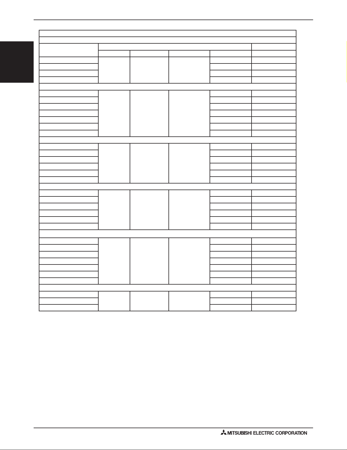
1. ELECTRICAL WORK
Symbols: MCA : Min.Circuit Amps (=1.25xFLA) FLA : Full Load Amps
IFM :Indoor Fan Motor
Model
PCFY-P15NKMU-E
PCFY-P24NKMU-E 0.52 / 0.52 0.41 / 0.41
PCFY-P30NKMU-E 1.22 / 1.22 0.97 / 0.97
PCFY-P36NKMU-E 1.22 / 1.22 0.97 / 0.97
Hz Volts Voltage range MCA(A) FLA(A)
60Hz 208 / 230V 188 to 253V
Indoor Unit IFM
0.44 / 0.44 0.35 / 0.35
PKFY-P06NBMU-E
PKFY-P08NBMU-E 0.19 / 0.19 0.15 / 0.15
PKFY-P12NHMU-E 0.38 / 0.38 0.30 / 0.30
PKFY-P15NHMU-E 0.38 / 0.38 0.30 / 0.30
PKFY-P18NHMU-E 0.38 / 0.38 0.30 / 0.30
PKFY-P24NKMU-E 0.37 / 0.37 0.29 / 0.29
PKFY-P30NKMU-E 0.54 / 0.54 0.43 / 0.43
PFFY-P06NEMU-E
PFFY-P08NEMU-E 0.32 / 0.34 0.25 / 0.27
PFFY-P12NEMU-E 0.34 / 0.38 0.27 / 0.30
PFFY-P15NEMU-E 0.40 / 0.44 0.32 / 0.35
PFFY-P18NEMU-E 0.48 / 0.53 0.38 / 0.42
PFFY-P24NEMU-E 0.59 / 0.64 0.47 / 0.51
PFFY-P06NRMU-E
PFFY-P08NRMU-E 0.32 / 0.34 0.25 / 0.27
PFFY-P12NRMU-E 0.34 / 0.38 0.27 / 0.30
PFFY-P15NRMU-E 0.40 / 0.44 0.32 / 0.35
PFFY-P18NRMU-E 0.48 / 0.53 0.38 / 0.42
PFFY-P24NRMU-E 0.59 / 0.64 0.47 / 0.51
PVFY-P12E00A
PVFY-P18E00A 1.53 / 1.38 1.22 / 1.10
PVFY-P24E00A 1.39 / 1.85 1.11 / 1.00
PVFY-P30E00A 2.50 / 2.25 2.00 / 1.80
PVFY-P36E00A 2.09 / 1.88 1.67 / 1.50
PVFY-P48E00A 2.23 / 2.00 1.78 / 1.60
PVFY-P54E00A 2.64 / 2.38 2.11 / 1.90
60Hz 208 / 230V 188 to 253V
60Hz 208 / 230V 188 to 253V
60Hz 208 / 230V 188 to 253V
60Hz 208 / 230V 188 to 253V
0.19 / 0.19 0.15 / 0.15
0.32 / 0.34 0.25 / 0.27
0.32 / 0.34 0.25 / 0.27
0.56 / 0.50 0.45 / 0.40
PWFY-P36NMU-E-BU
PWFY-P36NMU-E-AU 0.09 PWFY-P72NMU-E-AU 0.09 -
H2iSD-4
2010 Hyper-heating Y-SERIES SYSTEM DESIGN (Sept. 2010)
60Hz 208 / 230V 188 to 253V
25 -
Page 5
1. ELECTRICAL WORK
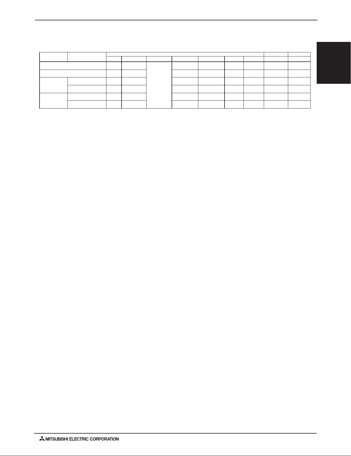
1-2-2. Electrical characteristics of Outdoor unit of cooling mode
Symbols: MCA : Min. Circuit Amps
PUHY-HP-T(S)JMU
Model
PUHY-HP72TJMU-A
PUHY-HP96TJMU-A
PUHY-HP
144TSJMU-A
PUHY-HP
192TSJMU-A
Tosizebreakers,see“RecommendedFuse/BreakerSize”intheSpecicationstable.
Unit Combination
PUHY-HP72TJMU-A
PUHY-HP72TJMU-A
PUHY-HP96TJMU-A
PUHY-HP96TJMU-A
60Hz
60Hz
60Hz
60Hz
60Hz
60Hz
VoltsHz
208 / 230V
208 / 230V
208 / 230V
208 / 230V
208 / 230V
208 / 230V
Voltage range
188 to 253V
SC : Starting Current RLA
Outdoor Units
RLA(A)
19.4 / 17.6
28.2 / 25.5
19.4 / 17.6
19.4 / 17.6
28.2 / 25.5
28.2 / 25.5
RLA(MAX)(A)
38.4 / 38.4
52.4 / 52.4
38.4 / 38.4
38.4 / 38.4
52.4 / 52.4
52.4 / 52.4
MOCP : Max. Over Current Protection
: Rated Load Amps
MCA(A)
59 / 54
74 / 68
59 / 54
59 / 54
74 / 68
74 / 68
101 / 92
127 / 116
101 / 92
101 / 92
127 / 116
127 / 116
MOCP
Compressor
15
15
15
15
15
15
Fan
Output(kW)SC(A)
0.92
0.92
0.92
0.92
0.92
0.92
SYSTEM DESIGN
Y-SERIES
2010 H2i
®
2010 Hyper-heating Y-SERIES SYSTEM DESIGN (Sept. 2010)
H2iSD-5
Page 6
2. M-NET CONTROL
2-1. Transmission Cable Length Limitations
®
Y-SERIES
2010 H2i
SYSTEM DESIGN
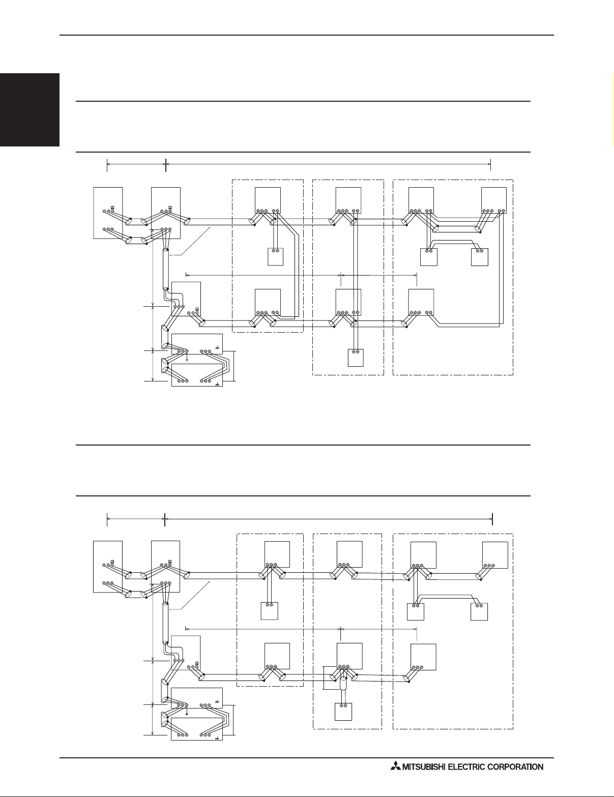
2-1-1. Using MA Remote controller
Long transmission cable causes voltage down, therefore, the length limitation should be obeyed to secure proper transmission.
Max. length via Outdoor (M-NET cable) L1+L2+L3+L4, L1+L2+L6+L7, L3+L4+L6+L7 <=500m[1640ft.] 1.25mm
Max. Total M-NET Wiring
Max. length to Outdoor (M-NET cable)
(L1 → 8) <=2km [6,560ft.] 1.25mm2 [AWG16] or thicker
∑
L1+L8, L3+L4, L6, L2+L6+L8, L7 <=200m[656ft.] 1.25mm2 [AWG16] or thicker
Max. length from MA to Indoor a1+a2, a1+a2+a3+a4 <=200m[656ft.] 0.3-1.25 mm
24VDC to AG-150A n <=50m[164ft.] 0.75-2.0 mm
L
8
Group1 Group3 Group5
OS
(52)
TB3
M2
TB7
M2SM2M1 M1 S
2
L
6
L
7
L
(51)
OC
TB3
M2M1 M1
TB7
AG-150A
Shielded wire
OC
(54 )
TB7
M1M2
S
TB3
M2M1
Power Supply Unit
PAC-SC51KUA
AB
S
V+V-FG
AB
S
V+V-FG
L
3
IC
(01)
TB5 TB15
M1 M2 12S
a1
AB
a2
MA
IC
(02)
TB15
TB5
12
M1 M2 S
n
OC, OS : Outdoor unit controller; IC: Indoor unit controller; MA: MA remote controller
L
1
M1 M2 S
M1 M2 S
IC
(04)
TB15
TB5
12
a2
L
4
IC
(03)
TB 15
TB5
12
a1
AB
MA
M1 M2 S
M1 M2 S
IC
(05)
TB15
TB5
12
a1
AB
MA
IC
(07)
TB15
TB5
12
2
[AWG16] or thicker
2
[AWG22-16]
2
[AWG18-14]
IC
(06)
TB5
M1 M2 S
a2
a4
AB
MA
TB15
12
a3
2-1-2. Using ME Remote controller
Long transmission cable causes voltage down, therefore, the length limitation should be obeyed to secure proper transmission.
Max. length via Outdoor (M-NET cable)
Max. Total M-NET Wiring
Max. length to Outdoor (M-NET cable) L1+L8, L3+L4, L6, L2+L6+L8, L7, L3+L5 <=200m[656ft.] 1.25mm
Max. length from ME to Indoor e1, e2+e3, e4 <=10m[32ft.]*1 0.3-1.25 mm
24VDC to AG-150A n <=50m[164ft.] 0.75-2.0 mm
*1. If the length from ME to Indoor exceed 10m [33ft.], use 1.25 mm
L
8
OS
(52)
TB3
M2
TB7
S
M2
OC, OS : Outdoor unit controller; IC: Indoor unit controller; ME: ME remote controller
H2iSD-6
OC
(51)
TB3
M2M1 M1
TB7
M2M1 M1
S
Shielded wire
2
L
TB7
M1 M2
L6L7
Power Supply Unit
PAC-SC51KUA
AG-150A
2010 Hyper-heating Y-SERIES SYSTEM DESIGN (Sept. 2010)
L1+L2+L3+L4, L1+L2+L6+L7,L1+L2+L3+L5, L3+L4+L6+L7
∑ (L1 → 8) <=2km [6,560ft.] 1.25mm
2
[AWG16] shielded cable, but the total length should be counted into Max. length via Outdoor.
L1
Group1 Group3
IC
(01)
TB5
M1 M2 S
e1
AB
(101)
ME
OC
(54 )
S
TB3
M2M1
AB
S
V+V-FG
L3
TB5
M1 M2 S
IC
(02)
n
AB
S
V+V-FG
IC
(04)
TB5
M1 M2 S
IC
(03)
TB5
M1 M2 S
L5
e4
AB
(103)
ME
<=500m[1640ft.] 1.25mm2 [AWG16] or thicker
2
[AWG16] or thicker
2
[AWG16] or thicker
2
[AWG22-16] *1
2
[AWG18-14]
Group5
IC
(05)
TB5
M1 M2 S
e2
AB AB
(105)
ME
L4
M1 M2 S
e3
IC
(07)
TB5
M1 M2 S
(155)
ME
IC
(06)
TB5
Page 7

2. M-NET CONTROL
2-2. Transmission Cable Specications
(Li)
—
Type of cable
Cable size
Remarks
Connected with simple remote controller.
Transmission cablesME Remote controller cables
Shielding wire (2-core)
CVVS, CPEVS or MVVS
1.25 [AWG16]
MA Remote controller cables
Sheathed 2-core cable (unshielded)
CVV
2
1.25 [AWG16]
1.25 [AWG16]
When 10m [32ft] is exceeded, use cables with
the same specification as transmission cables.
2
CVVS, MVVS : PVC insulated PVC jacketed shielded control cable
PE insulated PVC jacketed shielded communication cable
CPEVS :
CVV : PV insulated PVC sheathed control cable
1.25 [AWG16]
1.25 [AWG16]
Max length : 200m [656ft]
SYSTEM DESIGN
2010 H2i
Y-SERIES
2
2
®
2010 Hyper-heating Y-SERIES SYSTEM DESIGN (Sept. 2010)
H2iSD-7
Page 8
®
Y-SERIES
2010 H2i
SYSTEM DESIGN
2. M-NET CONTROL
2-3. System Conguration Restrictions
2-3-1. Common restrictions for the CITY MULTI system
For each Outdoor unit, the maximum connectable quantity of Indoor unit is specified at its Specifications table.
A) 1 Group of Indoor units can have 1-16 Indoor units;
B) Maximum 2 remote controllers for 1 Group; (MA/ME remote controllers cannot be present together in 1group.)
C) 1 LOSSNAY unit can interlock maximum 16 Indoor units; 1 Indoor unit can interlock only 1 LOSSNAY unit.
D) Maximum 3 System controllers are connectable when connecting to TB3 of the Outdoor unit.
E) Maximum 3 System controllers are connectable when connecting to TB7 of the Outdoor unit, if the transmission
power is supplied by the Outdoor unit.
F) 4 System controllers or more are connectable when connecting to TB7 of the Outdoor unit, if the transmission
power is supplied by the power supply unit PAC-SC51KUA. Details refer to 2-3-3-C.
*System controller connected as described in D) and E) would have a risk that the failure of connected Outdoor
unit would stop power supply to the System controller.
2-3-2. Ensuring proper communication power for M-NET
In order to ensure proper communication among Outdoor unit, Indoor unit, LOSSNAY and Controllers, the transmission
power situation for the M-NET should be observed. In some cases, Transmission booster should be used. Taking the
power consumption index of Indoor unit sized P06-P54 as 1, the equivalent power consumption index and supply
capability index of others are listed at Table 2-3-1 and Table 2-3-2.
Table 2-3-1 The equivalent power consumption by index Indoor units, LOSSNAY, controllers
Indoor, OA unitIndoor unit
Sized P06-P54
Sized P72,
P96
BC controller
CMB
1 701/41/2 31 21/2
*RC : Remote Controller
Table 2-3-2 The equivalent power supply capability index of Trans.Booster, Power supply unit, Connector TB3, TB7 of Outdoor unit.
Transmission Booster
PAC-SF46EPA
25
*If PAC-SC51KUA is used to supply power at TB7 side, no power supply need from Outdoor unit at TB7, Connector TB3 itself will therefore have 32.
Not applicable to the PUMY model.
Power supply unit
PAC-SC51KUA
With the equivalent power consumption values in Table 2-3-1 and Table 2-3-2, PAC-SF46EPA can be designed into the airconditioner system to ensure proper system communication according to 2-3-2-A, B, C.
2-3-2-A) Firstly, count from TB3 at TB3 side the total quantity of Indoor units and ME remote controller, Timers and System
controllers.If the total quantity reaches 40, a PAC-SF46EPA should be set.In this case, Indoor unit sized P72, 96 is
counted as 7 Indoor units, but MA remote controller(s), LOSSNAY is NOT counted.
2-3-2-B) Secondly, count from TB7 side to TB3 side the total transmission power consumption index. If the total power consumption
reaches 32, a PAC-SF46EPA should be set.Yet, if a PAC-SC51KUA is used to supply power at TB7 side, count from
index TB3 side only.
2-3-2-C) Thirdly, count from TB7 at TB7 side the total transmission power consumption index, If the total power consumption reaches
6, a PAC-SF46EPA should be set.
System example
2
5
MA RC.LOSSNAY
PAR-21MAA
PAC-YT51CRB
PAR-FA32MA
LGH-RX-E
PZ-41SLB
BM ADAPTER
BAC-HD150
ME Remote Contr. Timers, System Contr. ON/OFF Contr MN Converter.
PAR-F27MEA
PZ-52SF
PAC-SF44SRA
PAC-YT34STA
AG-150A
TC-24A
PAC-YT40ANRA CMS
GB-24A
4
System Controller
GB-50ADA
6
6
Outdoor unit
Connector TB3 and TB7 total *
32
-MNF-B
Outdoor unit
Connector TB7 only
6
CMS
-MNG-E
Power supply unit
PAC-SC51KUA
H2iSD-8
TB7 TB3
ME remote
TB7 TB3
Outdoor unit
M-NET
24VDC
CENTRALIZED CONTROLLER AG-150A
Centralized controller
(AG-150A)
Transmission booster (No.2) should be used,
if the total equivalent transmission power consumption reaches 5.
controller
Transmission booster (No.1) should be used,
if the total quantity of Indoor units and ME remote controllers
reaches 40, (Indoor unit sized P72, 96 is counted as 7);
or if the total equivalent transmission power consumption reaches 32.
LOSSNAY
unit
PZ-52SF
N3
2010 Hyper-heating Y-SERIES SYSTEM DESIGN (Sept. 2010)
N1
0201
UP
TRANSMISSION BOOSTER
MODEL
PAC-SF46EPA
220-240V:0.7A ~/N
POWER RATING
50
3.4kg
WEIGHT
MADE IN JAPAN
Transmission
booster
PAC-SF46EPA
(No.2)
LOSSNAY
unit
PZ-52SF
Within N4, the total equivalent transmission
power consumption should not exceed 25.
N4
UP
TRANSMISSION BOOSTER
MODEL
PAC-SF46EPA
220-240V:0.7A ~/N
POWER RATING
50
3.4kg
WEIGHT
MADE IN JAPAN
Transmission
booster
(No.1)
ME remote
controller
Within N2, conditions 1,2 should be followed.
1.The total quantity of Indoor units and ME remote controller
should not exceed 40.
*Indoor unit sized P72, 96 is counted as 7 units.
2.The total equivalent transmission power consumption
should not exceed 25.
N2
Page 9

2. M-NET CONTROL
The power to System controller (excluding LMAP03-U) is supplied via M-NET transmission line. M-NET transmission line
at TB7 side is called Central control transmission line while one at TB3 side is called Indoor-Outdoor transmission line.
There are 3 ways to supply power to the System controller .
A) Connecting to TB3 of the Outdoor unit and receiving power from the Outdoor unit.
B) Connecting to TB7 of the Outdoor unit and receiving power from the Outdoor unit.
C) Connecting to TB7 of the Outdoor unit but receiving power from power supply unit PAC-SC51KUA.
Maximum 3 System controllers can be connected to TB3.
If there is more than 1 Outdoor unit, it is necessary to
replace power supply switch connector CN41 with CN40
on one Outdoor unit.
Maximum 3 System controllers can be connected to TB7
and receiving power from the Outdoor unit.
It is necessary to replace power supply switch connector
CN41 with CN40 on one Outdoor unit.
2-3-3-A. When connecting to TB3 of the Outdoor unit and receiving power from the Outdoor unit.
2-3-3-B. When connecting to TB7 of the Outdoor unit and receiving power from the Outdoor unit.
2-3-3-C. When connecting to TB7 of the Outdoor unit but receiving power from PAC-SC51KUA.
2-3-3. Ensuring proper power supply to System controller
Outdoor unit
MA remote controller
Group Group
Indoor unit
M-NET transmission lines
(transmission lines
for central controller)
Outdoor unit
ME remote controller
Group Group
Indoor unit
Replacement of
CN41 with CN40
Use CN41
as it is.
TB7
TB3
System controller
(excluding LMAP03-E)
M-NET transmission lines
(Indoor-Outdoor transmission lines)
TB7
TB3
System
controller
Maximum 3 System controllers can be connected to TB3.
Fig. 2-3-3-A
M-NET transmission lines
(transmission lines
for central controller)
MA remote controller
ME remote controller
Group Group
Group Group
Indoor unit
Indoor unit
TB3
Outdoor unit
Outdoor unit
Replacement of
CN41 with CN40
Use CN41
as it is.
System
controller
TB7
TB7
TB3
Maximum 3 System controllers can be connected to TB7.
M-NET transmission lines
(Indoor-Outdoor transmission lines)
Fig. 2-3-3-B
PAC-SC51KUA
M-NET transmission lines
(transmission lines
for central controller)
MA remote controller
ME remote controller
Group Group
Group Group
Indoor unit
Indoor unit
TB3
Outdoor unit
Outdoor unit
Use CN41
as it is.
Use CN41
as it is.
System
controller
TB7
TB7
TB3
CAUTION
M-NET transmission lines
(Indoor-Outdoor transmission lines)
Fig. 2-3-3-C
When using PAC-SC51KUA to supply transmission
power, the power supply connector CN41 on the Outdoor
units should be kept as it is. It is also a factory setting.
1 PAC-SC51KUA supports maximum 1 AG-150A unit
due to the limited power 24VDC at its TB3.
However, 1 PAC-SC51KUA supplies transmission power
at its TB2 equal to 5 Indoor units, which is referable at
Table 2-3-2.
If PZ-52SF, Timers, System controller, ON/OFF controller
connected to TB7 consume transmission power more
than 5 (Indoor units), Transmission booster
PAC-SF46EPA is needed. PAC-SF46EPA supplies
transmission power equal to 25 Indoor units.
AG-150A*1 is recommended to connect to TB7 because it performs back-up to a number of data.
In an air conditioner system has more than 1 Outdoor units, AG-150A receiving transmission power through TB3 or TB7 on one of the Outdoor units would
have a risk that the connected Outdoor unit failure would stop power supply to AG-150A and disrupt the whole system.
When applying apportioned electric power function, AG-150A is necessary to connected to TB7 and has its own power supply unit PAC-SC51KUA.
Note: Power supply unit PAC-SC51KUA is for AG-150A.
*1: AG-150A is an example model of system controllers.
SYSTEM DESIGN
Y-SERIES
2010 H2i
®
2010 Hyper-heating Y-SERIES SYSTEM DESIGN (Sept. 2010)
H2iSD-9
Page 10

2. M-NET CONTROL
2-3-4. Power supply to LM adapter LMAP03U
1-phase 208-230V AC power supply is needed.
®
The power supply unit PAC-SC51KUA is not necessary when connecting only the LMAP03U. Yet, make sure to change
the power supply changeover connector CN41 to CN40 on the LM adapter.
2-3-5.
Y-SERIES
2010 H2i
SYSTEM DESIGN
2-3-6.
Power supply to BM ADAPTER
1-phase 100-240VAC power supply is needed.
The power supply unit PAC-SC51KUA is not necessary when only BM ADAPTER is connected.
Yet, make sure to move the power jumper from CN41 to CN40 on the BM ADAPTER.
Power supply to GB-50ADA-A
1-phase 100-240VAC power supply is needed.
The power supply unit PAC-SC51KUA is not necessary.
GB-50ADA-A supplies power through TB3, which equals 6 indoor units. (refer to Table 2-3-2)
H2iSD-10
2010 Hyper-heating Y-SERIES SYSTEM DESIGN (Sept. 2010)
Page 11
2. M-NET CONTROL
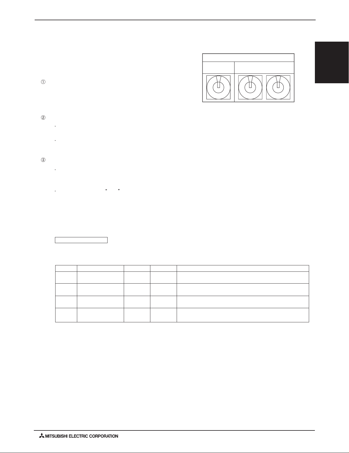
Branch
No. setting
Unit address No. setting
Rotary switch
In order to constitute CITY MULTI in a complete system, switch
operation for setting the unit address No. and connection No. is
required.
À Address No. of outdoor unit, indoor unit and remote controller.
The address No. is set at the address setting board.
In the case of R2 system, it is necessary to set the same No. at the
branch No. switch of indoor unit as that of the BC controller
connected. (When connecting two or more branches, use the lowest
branch No.)
Á Caution for switch operations
 MA remote controller
¥ Be sure to shut off power source before switch setting. If operated with power source on, switch can
not operate properly.
¥ When connecting only one remote controller to one group, it is always the main remote controller.
When connecting two remote controllers to one group, set one remote controller as the main remote controller
and the other as the sub remote controller.
¥ No units with identical unit address shall exist in one whole air conditioner system. If set erroneously,
the system can not operate.
¥ The factory setting is Main .
2-4-1. Switch operation
0
1
2
3
4
5
6
7
8
9
A
B
C
D
E
F
0
1
2
3
4
5
6
7
8
9
0
1
2
3
4
5
6
7
8
9
PAR-21MAA
The MA remote controller does not have the switches listed above.
Refer to the installation manual for the function setting.
Setting the dip switches
There are switches on the front of the remote controller. Remote controller Main/Sub and other function settings
are performed using these switches. Ordinarily, only change the Main/Sub setting of SW1.
(The factory settings are all “ON”.)
SW No
1
2
3
SW contents Main
Remote controller
Main/Sub setting
Temperature display
units setting
Cooling/heating display in AUTO mode
ON
Main
Celsius
Yes
OFF
Sub
Fahrenheit
No
Comment
Set one of the two remote controllers at one group to “Main”
When the temperature is displayed in [Fahrenheit], set to “No”.
When you do not want to display “Cooling” and “Heating” in the
Auto mode, set to “No”.
PAC-YT51CRB
4
Intake temperature
display
YesNo
When you do not want to display the intake temperature, set to
“No”.
2-4. Address Setting
SYSTEM DESIGN
Y-SERIES
2010 H2i
®
2010 Hyper-heating Y-SERIES SYSTEM DESIGN (Sept. 2010)
H2iSD-11
Page 12
2. M-NET CONTROL
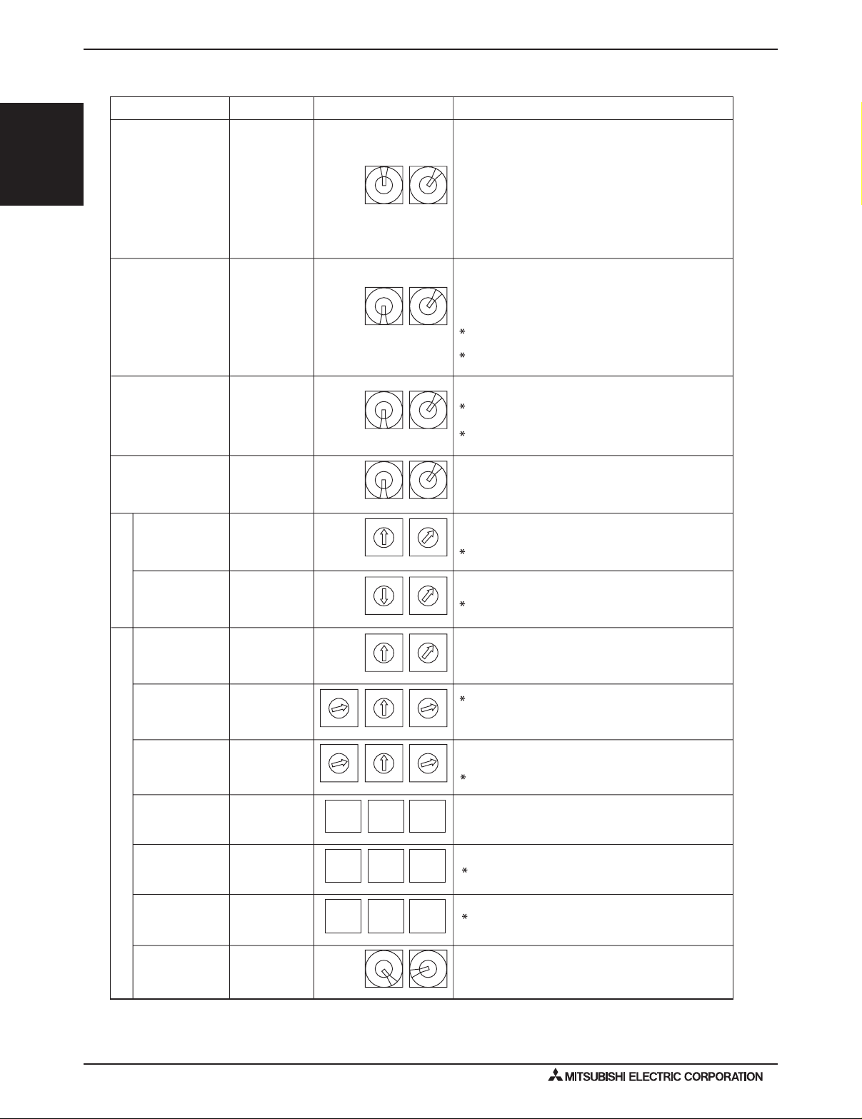
2-4-2. Rule of setting address
Unit
Indoor unit
ME, LOSSNAY
Remote controller
(Main)
ME, LOSSNAY
Remote controller
(Sub)
Address setting
01 ~ 50
52 ~ 99, 100
101 ~ 150
151 ~ 199, 200
NoteExample
The address of outdoor unit + 1
Please reset one of them to an address between 51
and 99 when two addresses overlap.
The address automatically becomes "100" if it is set
as "01~ 50"
The smallest address of indoor unit in the group + 100
The place of "100" is fixed to "1"
System remote
controller
ON/OFF remote
controller
000, 201 ~ 250
000, 201 ~ 250
Local remote controller
System controller
The address of main remote controller + 50
The address automatically becomes "200" if it is set
as "00"
10 1
10 1
0
1
2
3
4
5
6
7
8
9
0
1
2
3
4
5
6
7
8
9
10 1
10 1
0
1
2
3
4
5
6
7
8
9
0
1
2
3
4
5
6
7
8
9
0
1
2
3
4
5
6
7
8
9
0
1
2
3
4
5
6
7
8
9
0
1
2
3
4
5
6
7
8
9
0
1
2
3
4
5
6
7
8
9
0
1
2
3
4
5
6
7
8
9
0
1
2
3
4
5
6
7
8
9
0
1
2
3
4
5
6
7
8
9
10 1
10 1100
0
1
2
3
4
5
6
7
8
9
0
1
2
3
4
5
6
7
8
9
0
1
2
3
4
5
6
7
8
9
10 1100
LMAP03U
201 ~ 250
1
1
Fixed
Fixed
Group remote
controller
201 ~ 250
The smallest group No. to be managed + 200
For TC-24A, the address is set on the screen.
10 1
2
Fixed
2
Fixed
Outdoor unit
BC controller
(Main)
52 ~ 99, 100
Lowest address within the indoor units connected to
the BC controller (Sub) plus 50.
10 1
BC controller
(Sub)
51 ~ 99, 100
The smallest address of indoor unit in same refrigerant
system + 50
Assign sequential address numbers to the outdoor
units in one refrigerant circuit system. OC and OS are
automatically detected. (Note 2)
Please reset one of them to an address between 51
and 99 when two addresses overlap.
The address automatically becomes "100" if it is set
as "01~ 50"
Use the most recent address within the same group of
indoor units. Make the indoor units address connected
to the BC controller (Sub) larger than the indoor units
address connected to the BC controller (Main).
If applicable, set the sub BC controllers in an PURY
system in the following order:
(1)
Indoor unit to be connected to the BC controller (Main)
(2)
Indoor unit to be connected to the BC controller (No.1 Sub)
(3)
Indoor unit to be connected to the BC controller (No.2 Sub)
Set the address so that (1)<(2)<(3)
0
1
2
3
4
5
6
7
8
9
0
1
2
3
4
5
6
7
8
9
0
1
2
3
4
5
6
7
8
9
0
1
2
3
4
5
6
7
8
9
0
1
2
3
4
5
6
7
8
9
0
1
2
3
4
5
6
7
8
9
0
1
2
3
4
5
6
7
8
9
0
1
2
3
4
5
6
7
8
9
10 1
(Note1)
The smallest group No. to be managed is changeable.
The smallest group No. to be managed + 200
Note1: To set the address to "100", set it to "50"
Note2: Outdoor units OC and OS in one refrigerant circuit system are automatically detected.
OC and OS are ranked in descending order of capacity. If units are the same capacity, they are ranked in ascending
order of their address.
AG-150A
GB-50ADA
GB-24A
000, 201 ~ 250
10 1100
00 0
PAC-YG50ECA
000, 201 ~ 250
10 1100
BAC-HD150
000, 201 ~ 250
10 1100
Settings are made on the initial screen of AG-150A.
Settings are made with setting tool of BM ADAPTER.
00 0
00 0
®
Y-SERIES
2010 H2i
SYSTEM DESIGN
H2iSD-12
2010 Hyper-heating Y-SERIES SYSTEM DESIGN (Sept. 2010)
Page 13

2. M-NET CONTROL
2-4-3. System examples
Factory setting
Original switch setting of the outdoors, indoors, controllers and LMAP at shipment is as follows.
Outdoor unit : Address: 00, CN41: U (Jumper), DipSW2-1: OFF
Indoor unit : Address: 00
ME remote controller : Address: 101
LMAP : Address: 247, CN41: U (Jumper), DipSW1-2: OFF
Setting at the site
DipSW2-1(Outdoor) : When the System Remote Controller is used, all the Dip SW2-1 at the outdoor units should be
set to "ON".
DipSW1-2(LMAP) : When the LMAP is used together with System Remote Controller, DipSW1-2 at the LMAP
should be set to "ON".
CN40/CN41 : Change jumper from CN41 to CN 40 at outdoor control board will activate central transmission
power supply to TB7;
(Change jumper at only one outdoor unit when activating the transmission power supply
without using a power supply unit.)
Change jumper from CN41 to CN 40 at LMAP will activate transmission power supply to LMAP
itself;
Power supply unit is recommended to use for a system having more than 1 outdoor unit,
because the central transmission power supply from TB7 of one of outdoor units is risking that
the outdoor unit failure may let down the whole system controller system.
2-4-3-1. MA remote controller, Single-refrigerant-system, No System Controller
<Two outdoor units>
PUHY-HP-TSJMU
OC OS
<One outdoor unit>
PUHY-HP-TJMU
0000
CN41CN40CN41CN40 CN41CN40
* Dip SW2-1 remains OFF when only LMAP03U is used.
OC
00
SYSTEM DESIGN
Y-SERIES
2010 H2i
®
DipSW2-1
OFF
*1
To *1 or *2
DipSW2-1
OFF
TB3TB3
DipSW2-1
OFF
TB3
*2
Indoor unit
Group 2Group 1 Group 3 Group 4
00 00 00 00 00
SRU
*3
*3
TB15
TB15 TB15 TB15 TB15
MA R/C MA R/C MA R/C
(Main) (Sub)
TB5 TB5TB5 TB5 TB5
Wireless R/C
*3 For Wireless R/C and Signal receiver unit (SRU), channel 1, 2 and 3 are selectable and should be set to same channel.
NOTE:
1. Outdoor units OC and OS in one refrigerant circuit system are automatically detected.
OC and OS are ranked in descending order of capacity. If units are the same capacity, they are ranked in ascending order
of their address.
2. No address setting is needed.
3. For a system having more than 16 indoor unit, confirm the need of Booster at 2-3 "System configuration restrictions".
MA R/C
2010 Hyper-heating Y-SERIES SYSTEM DESIGN (Sept. 2010)
H2iSD-13
Page 14

®
Y-SERIES
2010 H2i
SYSTEM DESIGN
2. M-NET CONTROL
2-4-3-2. MA remote controller, Single-refrigerant-system, System Controller
<Two outdoor units>
PUHY-HP-TSJMU
OC OS
5251
CN41CN40CN41CN40 CN41CN40
DipSW2-1
ON
*1 *2
DipSW2-1
ON
TB3TB3
<One outdoor unit>
PUHY-HP-TJMU
OC
51
DipSW2-1
ON
TB3
To *1 or *2
Indoor unit
Group 2Group 1 Group 3 Group 4
01 02 03 04 05
SRU
*3
*3
TB15
TB15 TB15 TB15 TB15
MA R/C MA R/C MA R/C
(Main) (Sub)
MA R/C
TB5 TB5TB5 TB5 TB5
201
SC
Wireless R/C
*3 For Wireless R/C and Signal receiver unit (SRU), channel 1, 2 and 3 are selectable and should be set to same channel.
*SC can be connected to TB3 side or TB7 side;
Should SC connected to TB7 side, change Jumper from CN41 to CN40 at the Outdoor unit module so as to supply power to the SC.
NOTE:
1. Outdoor units OC and OS in one refrigerant circuit system are automatically detected.
OC and OS are ranked in descending order of capacity. If units are the same capacity, they are ranked in ascending order
of their address.
2. Address should be set to Indoor units and central controller.
3. For a system having more than 16 indoor unit, confirm the need of Booster at 2-3 "System configuration restrictions".
H2iSD-14
2010 Hyper-heating Y-SERIES SYSTEM DESIGN (Sept. 2010)
Page 15

2. M-NET CONTROL
2-4-3-3. MA remote controller, Multi-refrigerant-system, System Controller at TB7 side, Booster for long M-NET wiring
PUHY-HP-TSJMU
OC OS
DipSW2-1
ON
TB3
TB7TB7 TB7 TB7
TB3
PUHY-HP-TSJMU
OC OS
5251
CN41CN40CN41CN40 CN41CN40CN41CN40 CN41CN40
DipSW2-1
ON
Indoor unit
DipSW2-1
ON
9291
DipSW2-1
ON
TB3TB3
Group 2Group 1 Group 21
PUHY-HP-TJMU
OC
TB7
97
DipSW2-1
ON
TB3
01 02 03 30
PSU
Power supply
unit (PSU)
(PAC-SC51KUA)*2
000 or 201
SC*3
TB5 TB5TB5 TB2
Wireless R/C
SRU
*1
TB15
TB15 TB15 TB3
Transmission Booster
PAC-SF46EPA
MA R/C MA R/C
TB5
TB15
MA R/C
(Main) (Sub)
*1
Group 31 Group 34 Group 35
Group 33Group 32
SYSTEM DESIGN
Y-SERIES
2010 H2i
®
Indoor unit
41 45 46
SRU
TB15
*1
TB5 TB5 TB5
203
SC*3
42
TB5
142 143
ME R/CPZ-52SF
LOSSNAY
TB5
43
TB15
MA R/C
TB15
MA R/C
MA R/C
(Main) (Sub)
*1
Wireless R/C
*1 For Wireless R/C and Signal receiver unit (SRU), channel 1, 2 and 3 are selectable and should be set to same channel.
*2 System controller should connect to TB7 at Outdoor and use power supply unit together in Multi-Refrigerant-System.
For AG-150A, 24V DC should be used with the PAC-SC51KUA.
*3 When multiple system controllers are connected in the system, set the controller with more functions than others as a "main"
controller and others as "sub".
TC-24A is for exclusive use as a "main" system controller and cannot be used as a "sub" system controller.
Make the setting to only one of the system controllers for "prohibition of operation from local remote controller".
NOTE:
1. Outdoor units OC and OS in one refrigerant circuit system are automatically detected.
OC and OS are ranked in descending order of capacity. If units are the same capacity, they are ranked in ascending order
of their address.
2. Address should be set to Indoor units, LOSSNAY and central controller.
3. M-NET power is supplied by the Outdoor unit at TB3, while Indoor unit and
transmission use. The power balance is needed to consider for long M-NET wiring. Details refer to 2-3 "System configuration
restrictions".
ME remote controller consume the M-NET power for
2010 Hyper-heating Y-SERIES SYSTEM DESIGN (Sept. 2010)
H2iSD-15
Page 16

®
Y-SERIES
2010 H2i
SYSTEM DESIGN
2. M-NET CONTROL
2-4-3-4. ME remote controller, Single-refrigerant-system, No system controller
<Two outdoor units>
PUHY-HP-TSJMU
OC OS
DipSW2-1
OFF
TB3TB3
*1
5251
CN41CN40CN41CN40 CN41CN40
DipSW2-1
OFF
<One outdoor unit>
PUHY-HP-TJMU
OC
51
DipSW2-1
OFF
TB3
*2
To *1 or *2
Indoor unit
Group 2Group 1 Group 3 Group 4
01 02 03 04 05
TB5 TB5TB5
101
ME R/C
NOTE:
1. Outdoor units OC and OS in one refrigerant circuit system are automatically detected.
OC and OS are ranked in descending order of capacity. If units are the same capacity, they are ranked in ascending order of their
address.
2. Address should be set to Indoor units,
3. M-NET power is supplied by the Outdoor unit at TB3, while Indoor unit and ME RC consume the M-NET power for transmission
use. The power balance is needed to consider for long M-NET wiring. Details refer to 2-3 "System configuration restrictions".
controller and ME remote controllers.
system
102
ME R/C ME R/C ME R/C
2-4-3-5. ME remote controller, Single-refrigerant-system, System controller, LOSSNAY
<Two outdoor units>
PUHY-HP-TSJMU
OC OS
DipSW2-1
ON
TB3TB3
*1
5251
CN41CN40CN41CN40 CN41CN40
DipSW2-1
ON
<One outdoor unit>
PUHY-HP-TJMU
OC
51
DipSW2-1
ON
TB3
*2
TB5 TB5
104 105 155
ME R/C
To *1 or *2
201
SC
*SC can be connected to TB3 side or TB7 side;
Should SC connected to TB7 side, change Jumper from CN41 to CN40 at the Outdoor unit module so as to supply power to the SC.
NOTE:
1. Outdoor units OC and OS in one refrigerant circuit system are automatically detected.
OC and OS are ranked in descending order of capacity. If units are the same capacity, they are ranked in ascending order of their
address.
2. Address should be set to Indoor units, LOSSNAY central controller, ME remote controllers.
3. For a system having more than 16 indoor unit, confirm the need of Booster at 2-3 "System configuration restrictions".
H2iSD-16
2010 Hyper-heating Y-SERIES SYSTEM DESIGN (Sept. 2010)
Group 1 Group 4 Group 5
Indoor unit
01 04 05
TB5 TB5 TB5
101
ME R/C
Group 2Group 3
LOSSNAY
02
TB5
102 103
ME R/CPZ-52SF
TB5
03
104 105 155
ME R/C
ME R/C ME R/C
Page 17

2. M-NET CONTROL
2-4-3-6.
TB3
Power supply
unit (PSU)
(PAC-SC51KUA)
ME remote controller, Multi-refrigerant-system, System Controller at TB 7side, LOSSNAY, Booster for M-NET wiring
PUHY-HP-TSJMU
OC OS
DipSW2-1
ON
201
SC
PSU
*1
PUHY-HP-TSJMU
TB7TB7 TB7 TB7
OC OS
5251
CN41CN40CN41CN40 CN41CN40CN41CN40 CN41CN40
DipSW2-1
TB3TB3
Group 2Group 1 Group 21
TB3
DipSW2-1
ON
DipSW2-1
ON
Indoor unit
01 02 03 30
TB5 TB5TB5 TB2
202
SC *2
101
ME R/C
Group 31 Group 34 Group 35
Indoor unit
41 44 45
TB5 TB5 TB5
102
ME R/C
Group 32 Group 33
42
TB5
9291
ON
TB5
LOSSNAY
43
PUHY-HP-TJMU
OC
TB7
96
DipSW2-1
ON
TB3
Transmission Booster
PAC-SF46EPA
TB3
TB5
130 180
ME R/C ME R/C
SYSTEM DESIGN
Y-SERIES
2010 H2i
®
203
SC *2
*1 System controller should connect to TB7 at Outdoor and use power supply unit together in Multi-Refrigerant-System.
For AG-150A, 24V DC should be used with the PAC-SC51KUA.
*2 When multiple system controllers are connected in the system, set the controller with more functions than others as a "main"
controller and others as "sub".
TC-24A, AG-150A, GB-50ADA and GB-24A are for exclusive use as a "main" system controller and cannot be used as a "sub"
system controller.
Make the setting to only one of the system controllers for "prohibition of operation from local remote controller".
NOTE:
1. Outdoor units OC and OS in one refrigerant circuit system are automatically detected.
OC and OS are ranked in descending order of capacity. If units are the same capacity, they are ranked in ascending order of their address.
2. M-NET power is supplied by the Outdoor unit at TB3, while Indoor unit and ME
transmission use. The power balance is needed to consider for M-NET wiring. Details refer to "System configuration
restrictions".
141
ME R/C
142 143
ME R/C PZ-52SF
remote controller
144 145 195
ME R/C
consume the M-NET power for
ME R/C ME R/C
2010 Hyper-heating Y-SERIES SYSTEM DESIGN (Sept. 2010)
H2iSD-17
Page 18

®
Y-SERIES
2010 H2i
SYSTEM DESIGN
2. M-NET CONTROL
2-4-3-7. ME remote controller, Multi-refrigerant-system, No Power supply unit
PUHY-HP-TSJMU PUHY-HP-TJMU
OC OCOS
TB7
CN40
DipSW2-1
OFF
TB3
TB7
5251
CN41CN40CN41
DipSW2-1
OFF
TB3
01 02 03 04 05
TB7
56
CN41CN40
DipSW2-1
OFF
TB3
Group 1
Group 2
101
ME R/C
Group 3Group 4
105
ME R/C
0910 08 07 06
110
NOTE
It is necessary to change the connecter to CN40 on the outdoor unit control board (only one outdoor unit) when the group is set between other refrigerant systems.
It is necessary to set on the remote controller by manual when group sets on the different refrigerant system. Please refer to remote controller installation manual
ME R/C
107
ME R/C
2-4-3-8. ME remote controller, Multi-refrigerant-system, System Controller at TB7 side, No Power supply unit
PUHY-HP-TSJMU PUHY-HP-TJMU
OC OCOS
TB7
CN40
DipSW2-1
ON
TB3
TB7
5251
CN41CN40CN41
DipSW2-1
ON
TB3
TB7
DipSW2-1
TB3
56
ON
CN41CN40
Group 1
Group 2
01 02 03 04 05
.
201
SC
101
ME R/C
Group 3Group 4
105
ME R/C
0910 08 07 06
110
NOTE
It is necessary to change the connecter to CN40 on the outdoor unit control board (only one outdoor unit) when the group is set between other refrigerant systems.
It is necessary to set on the remote controller by manual when group sets on the different refrigerant system. Please refer to remote controller installation manual
H2iSD-18
2010 Hyper-heating Y-SERIES SYSTEM DESIGN (Sept. 2010)
ME R/C
107
ME R/C
.
Page 19

2. M-NET CONTROL
CM
2-4-3-9. TG-2000A + AG-150A/GB-50A
AG-150A/GB-50A can control max. 50 indoor units.
AG-150A can control max. 50 indoor units. AG-150A can control max. 150 indoor units via expansion controllers (PAC-YG50ECA).
TG-2000A can control max. 40 pieces of AG-150A*2 or GB-50A;
TG-2000A can control max. 40 pieces of AG-150A*1 or GB-50A;
TG-2000A can control max. 2000 indoor units.
TG-2000A can control max. 2000 indoor units.
AG-150A
000
24VDC
PUHY-HP-TJMU
OC
TB7
51
CN41CN40
SYSTEM DESIGN
Y-SERIES
2010 H2i
®
HUB
PC with
TG-2000A
*3
LAN
PSU
(PAC-SC51KUA)
AG-150A
000
24VDC
PSU
(PAC-SC51KUA)
DipSW2-1
ON
TB3
Group 2Group 1 Group 40
Indoor unit
01 02 03 42
TB5 TB5TB5 TB2
Wireless R/C
PUHY-HP-TSJMU PUHY-HP-TJMU
TB15
SRU
*2
*2
OC OS
TB7 TB7
DipSW2-1
ON
TB3TB3
MA R/
9291
CN41CN40CN41CN40 CN41CN40
DipSW2-1
ON
TB15 TB15 TB3
Transmission Booster
PAC-SF46EPA
OC
TB7
51
DipSW2-1
ON
TB3
TB5
TB15
A R/C
(Main) (Sub)
MA R/C
Group 2Group 1 Group 21
Indoor unit
01 02 03 30
TB5 TB5TB5 TB2
Transmission Booster
101
ME R/C
Indoor unit
41 42
TB5 TB5
141
ME R/C
NOTE
It is planned that GB-50ADA will be supported on TG-2000A Ver. 6.3* or later.
*1 When AG-150A is connected with expansion controllers (PAC-YG50ECA), AG-150A here means PAC-YG50ECA.
*2 For Wireless R/C and Signal receiver unit (SRU), channel 1, 2 and 3 are selectable and should be set to same channel.
*3 AG-150A connected with PAC-YG50ECA is compatible with TG-2000A Ver.6.10* or later.
102 130 180
ME R/C ME R/C ME R/C
Group 32Group 31 Group 33 Group 34
Interlocked
LOSSNAY
43
TB5 TB5 TB5
142
ME R/C
PAC-SF46EPA
2010 Hyper-heating Y-SERIES SYSTEM DESIGN (Sept. 2010)
TB3
44 45
144 145 195
ME R/C
TB5
ME R/C ME R/C
H2iSD-19
Page 20

®
Y-SERIES
2010 H2i
SYSTEM DESIGN
2. M-NET CONTROL
2-4-3-10. LMAP
LMAP can transmit max. 50 indoor units;
If system controller (SC) is used, DipSW1-2 at LMAP and DipSW2-1 at Outdoor unit should set to "ON".
Change Jumper from CN41 to CN40 to activate power supply to LMAP itself for those LMAP connected without system
controller (SC).
LMAP can transmit for max.
50 indoor units in single-refrigerant-system or multi-refrigerant-system.
CN41
PUHY-HP-TSJMU
OC OS
TB7 TB7
5251
CN41CN40CN41CN40
(LONWORKS adapter)
LMAP(01)
identified by Neuron ID
247
CN40
DipSW1-2
OFF
Power supply unit
(PAC-SC51KUA)
PSU
LMAP(02)
identified by Neuron ID
247
CN40
LONWORKS
DipSW1-2
24VDC
CN41
ON
TB3
DipSW2-1
OFF
Group 2Group 1
Group 40
DipSW2-1
OFF
TB3
Indoor unit
01 02 03 42
SRU
TB15
*1
TB15 TB15 TB3
MA R/C MA R/C
*1
TB7TB7 TB7 TB7
5251
CN41CN40CN41CN40
DipSW2-1
ON
TB3
Group 2
OC OS
DipSW2-1
ON
Transmission Booster
PAC-SF46EPA
9291
CN40CN41CN40 CN41CN40
CN41
DipSW2-1
ON
TB3TB3
TB5
(Main) (Sub)
TB3
Group 21
TB5 TB5TB5 TB2
AG-150A
000
Wireless R/C
PUHY-HP-TSJMU PUHY-HP-TSJMU PUHY-HP-TJMU
OC OS
DipSW2-1
ON
TB3
Group 1
Indoor unit
01 02 03 30
TB5 TB5TB5 TB2
TB3
TB5
TB15
MA R/C
OC
TB7
96
DipSW2-1
ON
LONW
LONW
LONW
H2iSD-20
PC
ORKS
ORKS
ORKS
Transmission Booster
101
ME R/C
Group 31 Group 34 Group 35
Indoor unit
41 44 45
TB5 TB5 TB5
102 130 180
ME R/C ME R/C ME R/C
Group 32 Group 33
LOSSNAY
42
TB5
43
TB5
PAC-SF46EPA
card
card
card
*1 For Wireless R/C and Signal receiver unit (SRU), channel 1, 2 and 3 are selectable and should be set to same channel.
For other equipments (Lighting, security, elevator etc.)
141
ME R/C
142 143
ME R/CPZ-52SF
144 145 195
ME R/C
ME R/C ME R/C
2010 Hyper-heating Y-SERIES SYSTEM DESIGN (Sept. 2010)
Page 21

2. M-NET CONTROL
2-4-3-11. BM ADAPTER
BM ADAPTER(01)
HUB
For other equipments (Lighting, security, elevator etc.)
BM ADAPTER can transmit for max.
50 indoor units in single-refrigerant-system or multi-refrigerant-system.
000
BAC net
BM ADAPTER(02)
201
CN41
CN40
BM ADAPTER can transmit max. 50 indoor units;
Change Jumper from CN41 to CN40 to activate power supply to BM ADAPTER itself for those BM ADAPTER connected
without the power supply unit.
Indoor unit
MA R/CMA R/C
(Main)(Sub)
MA R/C
SRU
Wireless R/C
*1
*1
01 02 03 42
TB15
TB5TB5TB5TB2
Transmission Booster
PAC-SF46EPA
TB5
TB15 TB15 TB3
TB15
Group 2Group 1
Group 40
Indoor unit
ME R/C ME R/CME R/C
01 02 03 30
TB5TB5TB5TB2
Transmission Booster
PAC-SF46EPA
TB5
ME R/C
101
102 130 180
TB3
Group 2
Group 1
Group 21
TB3
TB7TB7
TB7
TB3
OC OS
5251
TB3
91
OC
CN41CN40CN41CN40 CN41CN40
ON
DipSW2-1
ON
DipSW2-1
ON
DipSW2-1
ME R/CME R/C
Indoor unit
ME R/C
ME R/C
PZ-52SF-E
142 143
144 145 195
41 42
43
44 45
TB5TB5
LOSSNAY
TB5TB5 TB5
Group 32 Group 33Group 31 Group 34 Group 35
ME R/C
141
PUHY-HP-TSJMU PUHY-HP-TJMU
*1 For Wireless R/C and Signal receiver unit (SRU), channel 1, 2 and 3 are selectable and should be set to same channel.
HUB
CN41
CN40
TB3
TB7TB7
TB7
TB3
5251
OC OS
TB3
51
OC
CN41CN40CN41CN40 CN41CN40
OFF
DipSW2-1
OFF
DipSW2-1
OFF
DipSW2-1
PUHY-HP-TSJM
U
PUHY-HP-TJMU
<Two outdoor units>
<One outdoor unit>
SYSTEM DESIGN
Y-SERIES
2010 H2i
®
2010 Hyper-heating Y-SERIES SYSTEM DESIGN (Sept. 2010)
H2iSD-21
Page 22

3. PIPING DESIGN
3-1. R410A Piping Material
®
Y-SERIES
2010 H2i
SYSTEM DESIGN
Refrigerant pipe for CITY MULTI shall be made of phosphorus deoxidized copper, and has two types.
A. Type-O : Soft copper pipe (annealed copper pipe), can be easily bent with human's hand.
B. Ty pe-1/2H pipe : Hard copper pipe (Straight pipe), being stronger than Type-O pipe of the same radical thickness.
The maximum operation pressure of R410A air conditioner is 4.30 MPa [623psi] . The refrigerant piping should ensure the safety
under the maximum operation pressure. MITSUBISHI ELECTRIC recommends pipe size as Ta ble 3-1, or You shall follow the local
industrial standard. Pipes of radical thickness 0.7mm or less shall not be used.
Table 3-1. Copper pipe size and radial thickness for R410A CITY MULTI.
Size (mm) Size (inch)Radial thickness (mm) Pipe type
ø6.35 ø1/4"0.8 Ty pe-O
ø9.52 ø3/8"0.8 Ty pe-O
ø12.7 ø1/2"0.8 Ty pe-O
ø15.88 ø5/8"1.0 Ty pe-O
ø19.05 ø3/4"1.2 Ty pe-O
ø19.05 ø3/4"1.0 Ty pe-1/2H or H
ø22.2 ø7/8"1.0 Ty pe-1/2H or H
ø25.4ø1" 1.0Type-1/2H or H
ø28.58 ø1-1/8" 1.0Type-1/2H or H
ø31.75 ø1-1/4" 1.1Type-1/2H or H
ø34.93 ø1-3/8" 1.2Type-1/2H or H
ø41.28 ø1-5/8" 1.4
* F
or pipe sized ø19.05 (3/4") for R410A air conditioner, choice of pipe type is up to you.
* The figures in the radial thickness column are based on the Japanese standards and provided only as a reference. Use pipes that meet the
local standards.
Radial thickness (mil)
[32]
[32]
[32]
[40]
[48]
[40]
[40]
[40]
[40]
[44]
[48]
[56] Type-1/2H or H
Flare
Due to the relative higher operation pressure of R410A compared to R22, the flare connection should follow dimensions
mentioned below so as to achieve enough the air-tightness.
Flare pipe Pipe sizeA (For R410A) Flare nut Pipe size
ø6.35 [1/4"]
ø9.52 [3/8"]
A
ø12.70 [1/2"]
ø15.88 [5/8"]
ø19.05 [3/4"]
9.1 [3/8"]
13.2 [9/16"]
16.6 [11/16"]
19.7 [13/16"]
24.0 [1"]
B
ø6.35 [1/4"]
ø9.52 [3/8"]
ø12.70 [1/2"]
ø15.88 [5/8"]
ø19.05 [3/4"]
B (For R410A)
17.0 [3/4"]
22.0 [7/8"]
26.0 [1-1/16"]
29.0 [1-1/8"]
36.0 [1-7/16"]
(mm[in.]) (mm[in.])
H2iSD-22
2010 Hyper-heating Y-SERIES SYSTEM DESIGN (Sept. 2010)
Page 23

3. PIPING DESIGN
Table3-2-1-6. R410A Joint selection rule
Total down-stream Indoor capacity Joint
~ P72 CMY-Y102S-G2
P73 ~ P144 CMY-Y102L-G2
P145 ~ P234 CMY-Y202-G2
P235 ~ CMY-Y302-G2
*Concerning detailed usage of Joint parts, refer to its Installation Manual.
Table3-2-1-7. R410A Header selection rule
4-branch Header 8-branch Header 10-branch Header
CMY-Y104-G CMY-Y108-G CMY-Y1010-G
Total down-stream Indoor capacity
<=P72 <=P144 <=P234
* CMY-Y104-G can directly connect PUHY-HP72TJMU, but can NOT directly connect PUHY-HP96TJMU or above;
* CMY-Y108-G can directly connect PUHY-HP72-144T(S)JMU, but can NOT directly connect PUHY-HP192TSJMU
* CMY-Y1010-G can directly connect PUHY-HP72-192T(S)JMU;
* CMY-Y104-G can NOT connect P72, P96 Indoor, but CMY-Y108, Y1010-G can do;
* Concerning detailed usage of Header parts, refer to its Installation Manual.
H
h
H'
The first joint
Joint
b ca
L2
L1
IU
IU IUIU
d
IU
IU
f
IU
e
C
D
A
OU
B
Header
Note1. No Joint after Header; Piping direct to Indoor Unit from Header;
Note2. If the A/C system is designed to use Cooling-mode under Outside temperature 10°C [50°F], H'<=40m [131ft.];
Note3. As bents cause pressure loss on transportation of refrigerant, fewer bents design is better;
Piping length needs to consider the actual length and equivalent length which bents are counted.
Equivalent piping length = Actual piping length + "M" x Quantity of bent.
IU : Indoor unit , OU : Outdoor unit
g
Fig. 3-2-1A Piping scheme
3-2-1. PUHY-HP-72, 96TJMU Piping
Table3-2-1-1. Piping length (m [ft.])
Item Piping in the figure Max. length
Max. equivalent length
Total piping length A+B+C+D+a+b+c+d+e+f+g 300 [984'] Farthest IU from OU (L1) A+C+D+g / A+B+d 150 [492'] 175 [574']
Farthest IU from first Joint (L2) C+D+g / B+d 40 [131'] 40 [131']
Height between OU and IU (OU above IU)
H 50 [164'] -
Height between OU and IU (OU under IU)
H' 40 [131'] -
Height between IU and IU h 15 [49'] -
OU: Outdoor Unit, IU: Indoor Unit
Table3-2-1-3. Piping "A" size selection rule (mm [in.])
Outdoor and the first Joint Pipe(Liquid) Pipe(Gas)
PUHY-HP72TJMU=CMY-Y102S-G2 ø12.70 [1/2"] ø19.05 [3/4"]
PUHY-HP96TJMU=CMY-Y102L-G2 ø12.70 [1/2"] ø22.20 [7/8"]
Table3-2-1-4. Piping "B","C","D"size selection rule
(mm [in.])
Total down-stream Indoor capacity Pipe(Liquid) Pipe(Gas)
~ P54 ø9.52 [3/8"] ø15.88 [5/8"]
P55 ~ P72 ø9.52 [3/8"] ø19.05 [3/4"]
P73 ~ P108 ø9.52 [3/8"] ø22.20 [7/8"]
P109 ~ P144 ø12.70 [1/2"] ø28.58 [1-1/8"]
P145 ~ P234 ø15.88 [5/8"] ø28.58 [1-1/8"]
Table3-2-1-5.
Piping "a","b","c","d","e","f","g"size selection rule (mm [in.])
Indoor Unit size Pipe(Liquid) Pipe(Gas)
P06,P08,P12,P15,P18 ø6.35 [1/4"] ø12.70 [1/2"]
P24,P27,P30,P36,P48,P54 ø9.52 [3/8"] ø15.88 [5/8"]
P72 ø9.52 [3/8"] ø19.05 [3/4"]
P96 ø9.52 [3/8"] ø22.20 [7/8"]
Table3-2-1-2.
Bent equivalent length "M"
Outdoor Model M (m/
bends
[ft./
bends
])
PUHY-HP72TJMU 0.30 [0.99]
PUHY-HP96TJMU 0.35 [1.15]
Note4. Indoor capacity is described as its model size;
For example, PEFY-P08NMAU-E, its capacity is P06;
Note5. Total down-stream Indoor capacity is the summary of the model size of Indoors downstream.
For example, PEFY-P06NMAU-E+PEFY-P08NMAU-E: Total Indoor capacity=P06+P08=P14
Note6. Piping sized determined by the Total down-stream indoor capacity is NOT necessary
to be bigger than the up-stream one.
i.e. A>=B; A>=C>=D
3-2. Piping Design
SYSTEM DESIGN
Y-SERIES
2010 H2i
®
2010 Hyper-heating Y-SERIES SYSTEM DESIGN (Sept. 2010)
H2iSD-23
Page 24

3. PIPING DESIGN
Table3-2-2-4. R410A Joint selection rule
Total down-stream Indoor capacity Joint
~ P72CMY-Y102S-G2
P73~ P144 CMY-Y102L-G2
P145 ~ P234 CMY-Y202-G2
*First Joint is always CMY-Y202-G2;
*Concerning detailed usage of Joint parts, refer to its Installation Manual.
Outdoor Twinning Kit
CMY-Y100VBK2
Note1. No Joint after Header; Piping direct to Indoor Unit from Header;
Note2. If the A/C system is designed to use cooling-mode under outside temperature 10°C [50°F], H’<=40m [131ft].
Note3. As bents cause pressure loss on transportation of refrigerant, fewer bents design is better;
Piping length needs to consider the actual length and equivalent length which bents are counted.
Equivalent piping length=Actual piping length+"M" x Quantity of bent.
H (OU above IU)
h1
H' (OU under IU)
h2
1st Joint
Joint
ba
L2
L1
IU
IU IUIU
g
IU
e
IU
d
C
D
IU
f
E
T
S
A
B
Header
Capped
IU : Indoor unit , OU : Outdoor unit
Fig. 3-2-1B Piping scheme
c
2m [6.56ft]
To indoor unit
To indoor unit
To indoor unit
To indoor unit
2m [6.56ft] max
Trap (gas
pipe only)
Upward
incline
Downward
incline
Install the pipes from the outdoor unit to the branch
joint with a downward incline.
If the length of pipe between the branch joint and outdoor
unit exceeds 2m [6.56ft], provide at rap at a distance 2m [6.56ft] or
less from the branch joint.
OK
NO
3-2-2. PUHY-HP144-192TSJMU Piping
Table3-2-2-1. Piping length (m [ft.])
ItemPiping in the figureMax. length
Max. equivalent length
Total piping length
S+T+A+B+C+D+E+a+b+c+d+e+f+g
300 [984']Distance between OU and OU S+T 10[32']Height between OU and OU h2 0.1[0.3']Farthest IU from OU (L1)
S(T)+A+C+D+E+g / S(T)+A+B+c
150 [492'] 175 [574']
Farthest IU from the first Joint (L2) C+D+E+g / B+c 40 [131'] 40 [131']
Height between OU and IU (OU above IU)
H 50 [164']-
Height between OU and IU (OU under IU)
H' 40 [131']-
Height between IU and IU h1 15 [49']-
OU: Outdoor Unit, IU: Indoor Unit
Table3-2-2-3. Piping "A" size selection rule (mm [in.])
Outdoor and the first JointPipe(Liquid) Pipe(Gas)
CMY-Y100VBK2=CMY-Y202-G2 ø15.88[5/8"] ø28.58[1-1/8"]
For Piping size "S","T", please refer to specification of the Twining kit CMY-Y100VBK2 at the Outdoor unit's
external drawing.
Table3-2-2-2.
Bent equivalent length "M"
Outdoor Model M (m/bends [ft./bends])
PUHY-HP144TSJMU 0.50 [1.64]
PUHY-HP192TSJMU 0.50 [1.64]
OU
OU
®
Y-SERIES
2010 H2i
SYSTEM DESIGN
H2iSD-24
2010 Hyper-heating Y-SERIES SYSTEM DESIGN (Sept. 2010)
Page 25

3. PIPING DESIGN
+++
++
++
3-3. Refrigerant Charge Calculation
At the time of shipping, the outdoor unit is charged with the refrigerant. As this charge does not include the amount needed
for extended piping, additional charging for each refrigerant line will be required on site. In order that future servicing may be
properly provided, always keep a record of the size and length of each refrigerant line and the amount of additional charge
by writing it in the space provided on the outdoor unit.
(1) Calculation of additional refrigerant charge
Calculate the amount of additional charge based on the length of the piping extension and the size of the refrigerant
line.
Use the table to the below as a guide to calculating the amount of additional charging and charge the system
accordingly.
If the calculation results in a fraction of less than 0.1kg, round up to the next 0.1kg. For example, if the result of the
12.38kg, round the result up to 12.4kg.
calculation was
If the calculation results in a fraction of less than 1oz, round up to the next 1oz. For example, if the result of the
calculation was 435.1oz, round the result up to 436oz.
<Additional Charge>
Additional
refrigerant charge
Table3-2-3-1. Value of
(kg)
(oz)
Total capacity of connecting indoor units
Total length of liquid
= ++
(m)
(ft.)
Models 27
Models 28 54
Models 55 126
Models 127 144
Models 145 180
Models 181 234
Models 235
Example: PUHY-HP96TJMU
m [kg]
Indoor 1: P48A: 40 m a: 10 m
2: P36B: 10 m b: 5 m
3: P15 15 m c: 10 m
4: P12 10 m d: 10 m
5: P24 e: 10 m
The total length of liquid pipe of each size is as follows:
12.7 : A = 40 = 40 m
9.52 : B + C + D + a + b + e = 10 + 15 + 10 + 10 + 5 + 10 = 60 m
A
6.35 : c + d = 10 + 10 = 20 m
Total capacity of connecting Indoor units Pt :
Pt = P48 + P36 + P15 + P12 + P24 = P135, therefore = 3.5kg
0.29 (kg/m)
x
x 3.1 [oz/ft.]
Total length of liquid
(m) x 0.20 (kg/m)
(ft.)
x 2.15 [oz/ft.]
2.0 kg [71 oz]
2.5 kg [89 oz]
3.0 kg [106 oz]
3.5 kg [124 oz]
4.5 kg [159 oz]
5.0 kg [177 oz]
6.0 kg [212 oz]
Total length of liquid
(m) x 0.12 (kg/m)
(ft.)
x 1.29 [oz/ft.]
ft. [oz]
Indoor 1: P48A: 131ft. 32ft.
The total length of liquid pipe of each line is as follows:
Total capacity of connecting Indoor units Pt :
Pt = P48 + P36 + P15 + P12 + P24 = P135, therefore = 124oz
Total length of liquid
(m) x 0.06 (kg/m)
(ft.)
x 0.65 [oz/ft.]
2: P36B: 32ft. b: 16ft.
3: P15C: 49ft. c: 32ft.
4: P12D: 32ft. d: 32ft.
5: P24 e: 32ft.
A = 131 = 131ft.
+ a + b + e = 32 + 49 + 32 + 32 + 16 + 32 = 193ft.
Total length of liquid
(m) x 0.024 (kg/m)
(ft.)
x 0.26 [oz/ft.]
SYSTEM DESIGN
Y-SERIES
2010 H2i
®
m [kg]
Additional
refrigerant charge
(kg)
or
ft. [oz]
Additional
refrigerant charge
(oz)
B C D
e
a b c d
P15P36P48 P12
Total length of liquid
=+++
x 0.29 (kg/m)
0 (m) x 0.29 (kg/m)
=
0 0 40 x 0.12 60 x 0.06 20 x 0.024
= 12.4 kg
Total length of liquid
=+++
x 3.1 (oz/ft.)
0 (ft.) x 3.1 (oz/ft.)
=
0 0 131 x 1.29 193 x 0.65 64 x 0.26
= 436 [oz]
Total length of liquid
x 0.20 (kg/m)
0 (m) x 0.20 (kg/m)
++++
Total length of liquid
x 2.15 (oz/ft.)
0 (ft.) x 2.15 (oz/ft.)
++++
Total length of liquid
x 0.12 (kg/m)
40 (m) x 0.12 (kg/m)
Total length of liquid
x 1.29 (oz/ft.)
131 (ft.) x 1.29 (oz/ft.)
Total length of liquid
x 0.06 (kg/m)
60 (m) x 0.06 (kg/m)
Total length of liquid
x 0.65 (oz/ft.)
193 (ft.) x 0.65 (oz/ft.)
2010 Hyper-heating Y-SERIES SYSTEM DESIGN (Sept. 2010)
P24
Total length of liquid
x 0.024 (kg/m)
20 (m) x 0.024 (kg/m)
Total length of liquid
x 0.26 (oz/ft.)
64 (ft.) x 0.26 (oz/ft.)
H2iSD-25
3.5
+ 3.5
124
+ 124
Page 26

®
Y-SERIES
2010 H2i
SYSTEM DESIGN
4. OUTDOOR INSTALLATION
4-1. Installation Site Requirements
1.
Do not install in an area where the unit could be subjected to direct heat.
2.
Avoid installing the unit in a location where the operating sound could be an annoyance.
3. Avoid the sites where strong winds blow.
4.
Install on a stable, load-bearing surface.
5.
Ensure there is adequate drain flow from the unit when in heating mode
6.
See space requirements for installation and maintenance.
7. Do not install the unit in an environment that may have combustible gas, oil, steam, chemical gas like acidic solutions,
sulfur gas, etc.
8. To ensure an adequate flow velocity for the exhaust pipe, make sure its horizontal gradient is higher than 1/100.
H2iSD-26
2010 Hyper-heating Y-SERIES SYSTEM DESIGN (Sept. 2010)
Page 27

4. OUTDOOR INSTALLATION
4-2. Installation Clearance Space
In case of single installation
• Secure enough space around the unit as shown in the figure.
<A> : Top view
<B> :Side view
<C> : When there is little space up to an obstruction
(1) If the distance is 300 mm [11-13/16 in.] or more between the rear side and the wall
:Front
A
Unit height
:
B
300*
[11-13/16]
Back
:
C
:Air outlet guide (Procured at the site)
D
SYSTEM DESIGN
Y-SERIES
2010 H2i
®
A
450*
[17-23/32]
15* [19/32] 15* [19/32]
<A>
(2) If the distance is 100 mm [3-15/16 in.] or more between the rear side and the wall
100*
[3-15/16]
A
450*
[17-23/32]
50* [1-31/32] 50* [1-31/32]
<A>
(3) If the wall height (H) of the front, rear or side exceeds the wall height restriction
h
H
B
A
h
H
500
[19-11/16]
<B>
• When the height of the walls on the front, back or on the sides <H> exceeds the wall height limit as defined below,
add the height that exceeds the height limit <h> to the figures that are marked with an asterisk.
<Wall height limit> Front: Up to the unit height
Back: Up to 500mm [19-11/16 in.] from the unit bottom
Side: Up to the unit height
(4) If there are obstacles at the upper part of the unit
1000
45°
240
[39-3/8]
D
[9-15/32]
<C>
C
(Unit : mm [in.])
A
50 [1-31/32]
2010 Hyper-heating Y-SERIES SYSTEM DESIGN (Sept. 2010)
H2iSD-27
Page 28

®
Y-SERIES
2010 H2i
SYSTEM DESIGN
4. OUTDOOR INSTALLATION
In case of collective installation and continuous installation
:Front
A
Must be open
:
B
• When multiple units are installed adjacent to each other, secure enough space to allow for air circulation and
passageways between groups of units as shown in the figures.
• At least two sides must be left open.
• As with the single installation, add the height that exceeds the height limit <h> to the figures that are marked with
an asterisk.
• If there is a wall at both the front and the rear of the unit, install up to six units consecutively in the side direction and
provide a space of 1000mm [33-3/8] or more as inlet space/passage space for each six units.
: Wall height (H)
C
C
B B
A
C
C
30
[1-3/16]
450* 300*
[17-23/32] [11-13/16]
[3-15/16]
B B
A
C
100
[3-15/16]
450* 100*
[17-23/32]
B
C
AAA
C
C
B B
A
C
C
A
1000*
[39-3/8]
B
300*300*
900
900 300*
[11-13/16] [11-13/16] [11-13/16]
[35-7/16]
B
[35-7/16]
H2iSD-28
450*
[17-23/32] [17-23/32] [17-23/32]
450 450
100*
[3-15/16]
B
C
15*
AAA
450 450
[17-23/32] [17-23/32]
2010 Hyper-heating Y-SERIES SYSTEM DESIGN (Sept. 2010)
(Unit : mm [in.])
Page 29

4. OUTDOOR INSTALLATION
-
4-3. Piping Direction
4-3-1. Lifting method
· When lifting the unit with ropes, run the ropes under the unit and use the lifting hole.
· Support the unit at four points with two ropes, and avoid giving mechanical shock.
· Suspension rope angle must be 40° or less, so as to avoid compressing fan guard.
· Use two ropes, each at least 8m [26 ft.] in length
· Use ropes strong enough to support the weight of the unit.
· Always suspend the unit from four corners. (It is dangerous to suspend a unit from two corners and must not be attempt
ed.)
· Use protective pads to keep the ropes from scratching the panels on the unit.
SYSTEM DESIGN
Y-SERIES
2010 H2i
®
1 HP72 HP96
8 [26]
°
40
8 [26]
2
8 [26]
40°
8 [26]
CAUTION
Exercise caution when transporting products.
· Products weighing more than 20 kg [45 LBS] should not be carried alone.
· Do not carry the product by the PP bands.
· To avoid the risk of injury, do not touch the heat exchanger fins.
· Plastic bags may pose a risk of choking hazard to children. Tear plastic bags into pieces before disposing of them.
· When lifting and transporting outdoor units with ropes, run the ropes through lifting hole at the unit base. Securely
fix the unit so that the ropes will not slide off, and always lift the unit at four points to prevent the unit from falling.
2010 Hyper-heating Y-SERIES SYSTEM DESIGN (Sept. 2010)
H2iSD-29
Page 30

4. OUTDOOR INSTALLATION
4-3-2. Installation
®
Y-SERIES
2010 H2i
SYSTEM DESIGN
· Secure the unit with anchor bolts as shown in the figure below so that the unit will not topple over with strong wind or during an earthquake.
· Install the unit on a durable base made of such materials as concrete or angle steel.
· Ta ke appropriate anti-vibration measures (e.g., vibration damper pad, vibration isolation base) to keep vibrations and
noise from being transmitted from the unit through walls and floors.
· Install the unit in such a way that the corner of the angle bracket at the base of the unit shown in the figure below is
securely supported.
· Install the anchor bolt in such a way that the top end of the anchor bolt do not stick out more than 30 mm [1-3/16in].
· This unit is not designed to be anchored with post-installation-type anchor bolts, although by adding fixing brackets
anchoring with such type of anchor bolts becomes possible.
WARNING
Properly install the unit on a surface that can withstand the weight of
the unit.Unit installed on an unstable surface may fall and cause injury.
WARNING
Ta ke appropriate safety measures against strong winds and earthquakes to prevent the unit from falling.
[1-3/16in]
30mm
Install the unit in such a
way that the corner of
the angle bracket at the
base of the unit shown
in the figure is securely
supported. The brackets
may bend if they are not
securely supported.
Fixing bracket for postinstallation-type anchor
bolts.
Ta ke into consideration the durability of the base, water drainage route (Drain water is discharged from outdoor units
during operation.), piping route, and wiring route when performing foundation work.
4-3-3. Anchor bolt positions
<HP72, 96>
• Individual installation • Collective installation
724±3 [(28-13/32~28-5/8)]
AAAA
(For maintenance)
30 [1-3/16]
190 [7-1/2]
30 [1-3/16]
190 [7-1/2]
Leave a minimum of 30 mm [1-3/16 in.] between units.
HP72
760±2 [29-15/16(29-27/32~30)]
A
1060±2 [41-3/4(41-21/32~41-13/16)]
(Unit : mm [in.])
724±3 [(28-13/32~28-5/8)]
HP96PUHY
H2iSD-30
2010 Hyper-heating Y-SERIES SYSTEM DESIGN (Sept. 2010)
Page 31

4. OUTDOOR INSTALLATION
4-3-4. Installation
When the pipes and/or cables are routed at the bottom of the unit, make sure that the through hole at the base of
the unit does not get blocked with the installation base.
When the pipes are routed at the bottom of the unit, the base should be at least 100 mm [3-15/16 in] in height.
· HP72
(Unit : mm [in.]) (Unit : mm [in.])
· HP96
SYSTEM DESIGN
Y-SERIES
2010 H2i
®
(5-29/32)
221
251
186
80
(3-5/32)
150
(3-9/32)
83
Refrigerant service
valve <gas>
760
(29-15/16)
(Mounting pitch)
(5-23/32)
(3-13/32)
86
145
92
80
(3-5/32)
(8-23/32)
(9-29/32)
(7-11/32)
(5-3/16)
(5-29/32)
131
150
Refrigerant service
valve <liquid>
Bottom view
4-3-5. Refrigerant pipe routing
2X2-14(9/16)X20(13/16) Oval hole
18
(23/32)
(3-5/8)
(29-15/16)
(760)
(Mounting pitch)
724(721~727)
(28-13/32~28-5/8)
(28-17/32)
18
(23/32)
(10-11/16)
(11-7/8)
(8-17/32)
(5-3/16)
(5-29/32)
131
150
Refrigerant service
valve <liquid>
Installation base perpendicular to the unit’s front panelInstallation base parallel to the unit’s front panel
(5-29/32)
150271
301 83
216
(3-5/32) (3-5/32)
(3-9/32)
Refrigerant service
valve <gas>
1060
(41-3/4)
(Mounting pitch)
(5-23/32)
(3-5/16)
145
94 84
(3-23/32)
8080
Bottom view
2X2-14(9/16)X20(13/16) Oval hole
18
(23/32)
(29-15/16)
760
724(721~727)
(Mounting pitch)
(28-13/32~28-5/8)
(28-17/32)
18
(23/32)
Example of closure materials (field-supplied)
Fill the gap at the site
2010 Hyper-heating Y-SERIES SYSTEM DESIGN (Sept. 2010)
The gaps around the edges of through holes for pipes and wires on the
unit allow water or mice to enter the unit and damage its parts. Close
these gaps with filler plates.
This unit allows two types of pipe routing:
• Bottom piping
• Front piping
CAUTION
To prevent small animals, water and snow from
entering the unit and damage its parts, close the
gap around the edges of through holes for pipes
and wires with filler plates.
H2iSD-31
Page 32

4. OUTDOOR INSTALLATION
4-3-6. Twinning on the outdoor unit side
Reducer
±15°
The tilt angle of the reducer should be
within
±15° with the horizontal plane.
Note: See the following drawing for the fitting
position of the twinning pipe.
The tilt angle of the twinning pipe
The tilt angle of the twinning pipe must be within ±15° with the horizontal plane.
Tilting the twinning pipe more than specified will cause damage to the unit.
The length of the straight part of the pipe before the branching
For the twinning kit, always use the accessory piping parts.
The length of the straight part of pipe connected in front of the
twinning pipe must be 500 mm (19 in) or longer.
(Connect the field piping so that the length of the straight part
of pipe connected in front of the twinning pipe can be 500 mm
(19 in) or longer.)
If the length is less than 500 mm (19 in), it will cause damage
to the unit.
To Indoor unit
Less than 2 m (6 ft)
To Indoor unit
2m
(6 ft)
200 mm (7 in)
or over
Trap
(gas pipe only)
The piping connection
When connecting the twinning kit to the outdoor unit, note the following:
If the length of piping from the twinning kit to the outdoor unit is more than 2 m (6 ft),
install a trap within 2 m (6 ft) from the outdoor unit. The height of the trap must be 200
mm (7 in) or higher.
When installing the twinning kit in a higher position than the outdoor unit base, make
sure that the twinning kit is installed in a position lower than 200 mm (7 in) from the
outdoor unit base.
<2 m (6 ft) or less>
<PUHY-HP144TSJMU-A>
<PUHY-HP192TSJMU-A>
<More than 2 m (6 ft)>
Outdoor unit 1Outdoor unit 2
200 mm (7 in)
or less
Twinning pipe1
To Indoor unit
To indoor unit
Twinning pipe 1
200mm [7 in.]
or less
Outdoor unit 1
Outdoor unit 2
®
Y-SERIES
2010 H2i
SYSTEM DESIGN
H2iSD-32
2010 Hyper-heating Y-SERIES SYSTEM DESIGN (Sept. 2010)
Page 33

4. OUTDOOR INSTALLATION
4-3-7. Twinning on the outdoor unit side
See the following drawing for connecting the pipes between the outdoor units.
<PUHY-HP144 TSJMU-A>
<PUHY-HP192TSJMU-A>
Field piping
Twinning kit
Field piping
The length of the straight pipe
must be 500 mm [19 in.
]
or longer
SYSTEM DESIGN
Y-SERIES
2010 H2i
®
Field piping
Twinning kit
CAUTION
The length of the straight pipe must be 500mm[19in.] or longer.
If not, it may cause improper operation.
Field piping
The length of the straight pipe
must be 500 mm [19 in.] or longer
2010 Hyper-heating Y-SERIES SYSTEM DESIGN (Sept. 2010)
H2iSD-33
Page 34

• Snow hood
®
2010 H2i
4. OUTDOOR INSTALLATION
4-4. Weather Countermeasures
906 [35-11/16]
Y-SERIES
SYSTEM DESIGN
(See Note 1)
800 [31-1/2]
1324 [52-5/32]
86
[3-13/32]
H
(920 [36-1/4])
750 [29-17/32]
(760) [29-15/16]
Unit : mm[in]
453 [17-27/32] 453 [17-27/32]
910 [35-27/32]
760 [29-15/16]
<Side view><Front view>
Outlet
453 [17-27/32]
Inlet
Note:
1.Height of frame base for snow damage prevention (H) 12 inches above the average snowfall. Width of frame base shall not
exceed that of the unit. The frame base shall be made of angle steel, etc., and designed so that snow and wind slip through
the structure. (If frame base is too wide, snow will be accumulated on it.)
2.Install unit so that wind will not directly lash against openings of inlet and outlet ducts.
3.Build frame base at customer referring to this figure.
Material: Galvanized steel plate 1.2T [1/16 in T]
Painting: Overall painting with polyester powder
Color: Munsell 5Y8/1 (same as that of unit)
4.When the unit is used in a cold region and the heating operation is continuously performed for a long time when the outside air
temperature is below freezing, install a heater to the unit base or take other appropriate measures to prevent water from
freezing on the base.
Countermeasure to wind
Referring to the figure shown below, take appropriate measures which will suit the actual situation of the place for installation.
Wind
H2iSD-34
Install the outdoor unit where seasonal
winds do not blow directly against the
unit, such as behind a building.
Install the outdoor unit to avoid having
seasonal winds against the front of air
outlet/inlet on the unit.
2010 Hyper-heating Y-SERIES SYSTEM DESIGN (Sept. 2010)
Page 35

4. OUTDOOR INSTALLATION
Prevailing
Outdoor Units
Building Wall
12"
1-3/16"
OK
Concrete Pad
4-5. Low Ambient Kit Application Guidelines
General Unit Placement and Clearances
• Outdoor units should be located in an area protected from
prevailing winds.
• In high wind locations, it may be advisable to install the outdoor
units within a walled area.
• Hood discharge should be directed away from or perpendicular
to the prevailing winds. Do not direct the hood discharge towards
prevailing winds.
• When using the low ambient components, add an additional 7” to
the standard mounting clearances.
Note:
Equipment supports must elevate the unit at least 12” above the average
expected snow depth or 12” above the ground, whichever is higher. The
equipment supports must be an open construction to minimize snow drifting
and/or ice formation during defrost.
Wind
Top View
SYSTEM DESIGN
Y-SERIES
2010 H2i
®
If the units are surrounded by an enclosure, the hood must be
positioned that the air is directed out and over the walls to prevent
air recirculation.
Equipment Supports
When modules are combined, they should be placed a minimum of 1-3/16”
apart.Bydoingso,onlyonesetofsidewinddeectors(SWD-1)are
required per group of modules.
Theequipmentsupportmustbermlyattachedtothegroundorstructure.
The outdoor unit must be properly attached to the equipment support with
3/8” stainless steel or equal strength to at least a grade 5 bolt.
Note:
If the outdoor unit is located in an area with continuous high winds,
additional braced may be required. Contact your distributor for
assistance.
Minimum 3/8”
stainless steel or
harder bolts
2010 Hyper-heating Y-SERIES SYSTEM DESIGN (Sept. 2010)
H2iSD-35
Page 36

Important!
For all roof top
installations, safety
straps must be
attached between the
hood(s) and the unit
mounting structure.
®
Y-SERIES
2010 H2i
SYSTEM DESIGN
4. OUTDOOR INSTALLATION
Additional Rooftop Mounting Guidelines
Ground-level installation is preferred for outdoor units that include a low
ambient kit. If ground-level installation is not possible, follow general, as
well all additional installation guidelines for rooftop mounting. If you have
any questions, please contact your distributor.
Note:
Low ambient hood(s) increase the overall height of the outdoor
units and make them more susceptible to wind stresses. Follow
all guidelines when using these for rooftop applications.
• Straps must be attached to the hood where they will not interfere with
the movement of the dampers.
Note:
For all rooftop installation, safety straps must be attached between the
hood(s) and the equipment support structure. Straps should be 3/16” (or
larger) vinyl-coated cables.
• Straps must be connected to both the hood and mounting structure
through using ¼” diameter (or larger) bolt.
• Theoutdoorunitandequipmentsupportshouldbermly
attached to the structure. If the equipment support does not attach to the structure, refer to the support manufacturer’s
guidelines for proper size and construction.
Safety strap
Provided by others
Dependingonlocation,exposureandotherfactorsinuencingwind
access or blockage, additional support may be required such as
shown at right. Contact your distributor for assistance.
H2iSD-36
2010 Hyper-heating Y-SERIES SYSTEM DESIGN (Sept. 2010)
Page 37

5. STANDARD AND SEACOAST (BS) PROTECTION TREATMENT
5-1. H2i Y-Series
Component Base Material
External Panel Base
External Front Panel
Pillar
Compressor Cover
Fin Guard Steel Wires
Fan Guard and Drum
Fan
Fan Motor Frame Galvanized Steel Sheet
Fan Motor Shaft High-carbon S35C Steel
Fan Motor Support Galvanized Steel Sheet
Heat Exchanger
(Fin Only)
Electrical Parts Box
Printed Circuit Board Epoxy Resin
Screws Steel
Alloyed Galvanized Steel
Sheet
Alloyed Galvanized Steel
Sheet
Alloyed Galvanized Steel
Sheet
Galvanized Steel Sheet
Galvanized Aluminum
Sheet
Weather-resistant
Polypropylene Plastic
Weather-resistant Acrylic
Nitrile Styrene Plastic
Aluminum Plate
Galvanized Steel Sheet
Galvanized Aluminum
Sheet
Standard
Models
● ●
●
●
●
● ●
● ●
● ●
● ●
● ●
●
●
●
●
● ●
Seacoast
Protection
Models (-BS)
●
●
●
●
●
●
●
Surface
Treatment
Thermoset Polyester-resin
Powder Coating
Polyester-resin Coating ≥15μm ≥5μm
Thermoset Polyester-resin
Powder Coating
Polyester-resin Coating ≥30μm
Thermoset Polyester-resin
Powder Coating
No Treatment
Thermoset Polyester-resin
Powder Coating
Weather-resistant
Polypropylene-resin Coating
No Treatment
No Treatment
No Treatment
Rust-prevention Coating
No Treatment
Thermoset Polyester-resin
Powder Coating
Cellulose- and Polyurethaneresin Coating (Blue Fin)
(no unusual rust development
to 480 hours)
Cellulose- and Polyurethaneresin Coating (Blue Fin)
(no unusual rust development
to 960 hours)
No Treatment
Thermoset Polyester-resin
Powder Coating
No Treatment
Polyurethane Coating ≥10μm
Zinc-nickel Alloy Plating with
a Chromate Film
External Surface Internal Surface
Coating Thickness
≥70μm ≥70μm
≥85μm ≥75μm
≥70μm ≥70μm
≥70μm ≥70μm
≥300μm ≥300μm
≥70μm ≥70μm
≥1μm
≥1-1.5μm
≥70μm
≥5μm
SYSTEM DESIGN
Y-SERIES
2010 H2i
®
Application Guide
Direct Exposure to Sea Breezes
Facing Inland Seacoast Protection (-BS) Models Standard Models
Facing Sea Seacoast Protection (-BS) Models
On an Island Seacoast Protection (-BS) Models
Indirect Exposure to Sea Breezes
Facing Inland Seacoast Protection (-BS) Models Standard Models
Facing Sea Seacoast Protection (-BS) Models
On an Island Seacoast Protection (-BS) Models
Material
Test
Conditions
Test
Results
984′(300m) 1,640′(500m) 3,281′(1km)
Thermoset Polyester-resin
Powder Coating
Salt-spray T est Method: JIS
K2371 based on ISO9227
Conform to JRA9002 Criteria
(960-hour test)
Distance from the Sea
Cellulose- and Polyurethane-
resin Coating (Blue Fin)
Salt-spray T est Method: JIS Z2371
based on ISO9227
No unusual rust
development to
480 hours
No unusual rust
development to
960 hours
2010 Hyper-heating Y-SERIES SYSTEM DESIGN (Sept. 2010)
For optimum performance, follow the cautions
listed below.
1. Avoid installing the unit in a location that is
subjected to direct sea winds.
2. Do not attach a sunshade to the unit. Let the rain
wash away any salt residue that may adhere to the
unit.
3. Unit should be installed following instructions
for proper operation and to ensure optimum water
drainage.
4. Periodically wash the unit.
5. If the panels become scratched, repair as soon as
possible.
6. Inspect the unit at regular intervals. Paint the unit
or replace parts when necessary.
“Blue Fin” treatment is an anti-corrosion treatment that
is applied to the condenser coil to protect it against
airborne contaminants.
H2iSD-37
Page 38

6. CAUTIONS
R410A refrigerant is harmless and incombustible. R410A is heavier than the indoor air in density. Leakage of the refrigerant in a room
has possibility to lead to a hypoxia situation. Therefore, the critical concentration specified below shall not be exceeded even if the leakage
happens.
Critical concentration
Critical concentration is the maximum refrigerant concentration at which no harm would occur if immediate measures are taken
when refrigerant leakage happens.
Critical concentration of R410A: 0.30kg/m
3
(The weight of refrigeration gas per 1 m
3
[1 ft3] air
conditioning space.);
The critical concentration is per ISO5149, EN378-1 (other codes and standards may establish different values for critical concentration).
For CITY MULTI systems, the concentration of refrigerant leaked should not exceed the critical concentration in any situation.
[0.0187 lbs./ft
3
]
The maximum refrigerant leakage concentration (Rmax) is defined as the result of the possible maximum refrigerant weight (Wmax)
leaked into a room divided by its room capacity (V). The refrigerant weight includes itsoriginal charge and additional charge at the site.
The additional charge is calculated according to "
PUHY-P-T(S)HMU/Y(S)HMU's refrigerant charging calculation
", and shall not be
over charged at the site
.
Procedure 6-2-1~3 tells how to confirm maximum refrigerant leakage concentration (Rmax) and how to take
Refrigerant pipe
to Outdoor unit
Indoor unit
Opening
Ventilation air supply fan (always ON)
Indoor space
(Floor)
Fig. 6-2. air supply always ON
Refrigerant pipe
to Outdoor unit
Indoor unit
Opening
Sensor for refrigerant leakage (Oxygen sensor or refrigerant sensor).
[At 0.3m height from the floor]
Ventilation air supply fan
Indoor space
(Floor)
Fig. 6-3.
air supply upon sensor action
Note 1. Countermeasure 3 should be done in a proper way in which the ventilation air supply shall be on whenever the leakage happens .
Note 2. In principle, MITSUBISHI ELECTRIC requires proper piping design, installation and air-tight testing after installation to avoid leakage happening.
In the area should earthquake happen, anti-vibration measures should be fully considered.
The piping should consider the extension due to the temperature variation.
Outdoor unit (No.1)
Flow of refrigerant
Indoor unit
Maximum refrigerant leakage concentration (Rmax)
Outdoor unit (No.1) Outdoor unit (No.2)
Indoor unit
Flow of refrigerant Flow of refrigerant
Rmax=Wmax / V
Maximum refrigerant leakage concentration (Rmax)
Rmax=Wmax / V
where, Wmax=W1+W2
W1: Refrigerant weight of Outdoor unit No.1
W2: Refrigerant weight of Outdoor unit No.2
Fig. 6-1 The maximum refrigerant leakage concentration
6-2-1.Find the room capacity (V),
If a room having total opening area more than 0.15% of the floor area at a low position with another room/space, the two rooms/space are
considered as one. The total space shall be added up.
6-2-2.Find the possible maximum leakage (Wmax) in the room. If a room has Indoor unit(s) from more than 1 Outdoor unit, add up the refriger-
ant of the Outdoor units.
6-2-3.Divide (Wmax) by (V) to get the maximum refrigerant leakage concentration (Rmax).
6-2-4.Find if there is any room in which the maximum refrigerant leakage concentration (Rmax) is over 0.30kg/m
3
If no, then the CITY MULTI is safe against refrigerant leakage.
If yes, following countermeasure is recommended to do at site.
Countermeasure 1: Let-out (making V bigger)
Design an opening of more than 0.15% of the floor area at a low position of the wall to let out the refrigerant whenever leaked.
e.g. make the upper and lower seams of door big enough.
Countermeasure 2: Smaller total charge (making Wmax smaller)
e.g. Avoid connecting more than 1 Outdoor unit to one room.
e.g. Using smaller model size but more Outdoor units.
e.g. Shorten the refrigerant piping as much as possible.
Countermeasure 3:
As the density of the refrigerant is bigger than that of the air.
Ventilation air supply solution refers to Fig. 6-2~3.
countermeasures against a possible leakage.
Ventilation air in from the ceiling.
Ventilation air from the ceiling is better than air exhausting from the ceiling.
Ventilation Ventilation
[0.0187 lbs./ft. ].
3
e.g. Remove unit from space.
The installer and/or air-conditioning system specialist shall follow local safety regulations and standards regarding refrigerant leakage. The
following standard may be applicable if a local regulation or standard is available.
®
2010 H2i
6-1. Refrigerant Properties
Y-SERIES
SYSTEM DESIGN
6-2. Conrm the Critical Concentration Levels and Perform Countermeasures
H2iSD-38
2010 Hyper-heating Y-SERIES SYSTEM DESIGN (Sept. 2010)
 Loading...