

Page 1

PURY-HP-T(S)KMU,-Y(S)KMU (September 2014)
H2i-R2-1
© 2014 Mitsubishi Electric US, Inc.
CITY MULTI® H2i® R2-SERIES HYPER-HEATING INVERTER SERIES
OUTDOOR UNITS
1. SPECIFICATIONS ..................................................................................................................................................H2i-R2-4
1-1. PURY-HP72~192T(S)KMU-A-H Specications .............................................................................................H2i-R2-4
1-2. PURY-HP72~192Y(S)KMU-A Specications ................................................................................................H2i-R2-7
2. EXTERNAL DIMENSIONS ...................................................................................................................................H2i-R2-11
3. CENTER OF GRAVITY ........................................................................................................................................H2i-R2-17
4. ELECTRICAL WIRING DIAGRAMS .....................................................................................................................H2i-R2-18
5. REFRIGERANT CIRCUIT DIAGRAMS ................................................................................................................H2i-R2-20
6. SOUND PRESSURE LEVELS .............................................................................................................................H2i-R2-22
7. CAPACITY TABLES .............................................................................................................................................H2i-R2-24
7-1. Correction by Temperature (Standard Performance) in Fahrenheit ............................................................H2i-R2-24
7-1-1. Cooling Capacity/Power Input with PURY-HP72TKMU-A-H ..........................................................H2i-R2-24
7-1-2. Cooling Capacity/Power Input with PURY-HP96TKMU-A-H ..........................................................H2i-R2-25
7-1-3. Cooling Capacity/Power Input with PURY-HP144TSKMU-A-H .....................................................H2i-R2-26
7-1-4. Cooling Capacity/Power Input with PURY-HP192TSKMU-A-H .....................................................H2i-R2-27
7-1-5. Heating Capacity/Power Input with PURY-HP72TKMU-A-H .........................................................H2i-R2-28
7-1-6. Heating Capacity/Power Input with PURY-HP96TKMU-A-H .........................................................H2i-R2-29
7-1-7. Heating Capacity/Power Input with PURY-HP144TSKMU-A-H .....................................................H2i-R2-30
7-1-8. Heating Capacity/Power Input with PURY-HP192TSKMU-A-H .....................................................H2i-R2-31
7-2. Correction by Temperature (High Heating Performance) in Fahrenheit ......................................................H2i-R2-32
7-2-1. Heating Capacity/Power Input (High Heat Performance) with PURY-HP72TKMU-A-H ...............H2i-R2-32
7-2-2. Heating Capacity/Power Input (High Heat Performance) with PURY-HP96TKMU-A-H ................H2i-R2-33
7-2-3. Heating Capacity/Power Input (High Heat Performance) with PURY-HP144TSKMU-A-H ............H2i-R2-34
7-2-4. Heating Capacity/Power Input (High Heat Performance) with PURY-HP192TSKMU-A-H ...........H2i-R2-35
7-3. Correction by Temperature (Intelligent Heat Performance) in Fahrenheit ...................................................H2i-R2-36
7-3-1. Heating Capacity/Power Input (Intelligent Heat Performance) with PURY-HP72TKMU-A-H ........H2i-R2-36
7-3-2. Heating Capacity/Power Input (Intelligent Heat Performance) with PURY-HP96TKMU-A-H ........H2i-R2-37
7-3-3. Heating Capacity/Power Input (Intelligent Heat Performance) with PURY-HP144TSKMU-A-H ....H2i-R2-38
7-3-4. Heating Capacity/Power Input (Intelligent Heat Performance) with PURY-HP192TSKMU-A-H ....H2i-R2-39
7-4. Correction by Temperature/Total Indoor in Fahrenheit ................................................................................H2i-R2-40
7-4-1. Cooling Capacity with PURY-HP72TKMU-A-H .............................................................................H2i-R2-40
7-4-2. Cooling Capacity with PURY-HP96TKMU-A-H ..............................................................................H2i-R2-44
7-4-3. Cooling Capacity with PURY-HP144TSKMU-A-H .........................................................................H2i-R2-48
7-4-4. Cooling Capacity with PURY-HP192TSKMU-A-H .........................................................................H2i-R2-52
7-4-5. Cooling Capacity with PURY-HP72YKMU-A ..................................................................................H2i-R2-56
7-4-6. Cooling Capacity with PURY-HP96YKMU-A ..................................................................................H2i-R2-60
7-4-7. Cooling Capacity with PURY-HP144YSKMU-A .............................................................................H2i-R2-64
7-4-8. Cooling Capacity with PURY-HP192YSKMU-A .............................................................................H2i-R2-68
7-4-9. Heating Capacity with PURY-HP72TKMU-A-H ..............................................................................H2i-R2-72
7-4-10. Heating Capacity with PURY-HP96TKMU-A-H ............................................................................H2i-R2-75
7-4-11. Heating Capacity with PURY-HP144TSKMU-A-H .......................................................................H2i-R2-78
7-4-12. Heating Capacity with PURY-HP192TSKMU-A-H .......................................................................H2i-R2-81
7-4-13. Heating Capacity with PURY-HP72YKMU-A ...............................................................................H2i-R2-84
7-4-14. Heating Capacity with PURY-HP96YKMU-A ..............................................................................H2i-R2-87
7-4-15. Heating Capacity with PURY-HP144YSKMU-A ...........................................................................H2i-R2-90
7-4-16. Heating Capacity with PURY-HP192YSKMU-A ...........................................................................H2i-R2-93
7-4-17. Heating Capacity [High Heat Performance Mode] with PURY-HP72TKMU-A-H .........................H2i-R2-96
7-4-18. Heating Capacity [High Heat Performance Mode] with PURY-HP96TKMU-A-H .........................H2i-R2-99
Page 2

H2i-R2-2
PURY-HP-T(S)KMU,-Y(S)KMU (September 2014)
© 2014 Mitsubishi Electric US, Inc.
H2i® R2-SERIES HYPER-HEATING INVERTER SERIES
7-4-19. Heating Capacity [High Heat Performance Mode] PURY-HP144TSKMU-A-H .........................H2i-R2-102
7-4-20. Heating Capacity [High Heat Performance Mode] with PURY-HP192TSKMU-A-H ...................H2i-R2-105
7-4-21. Heating Capacity [High Heat Performance Mode] with PURY-HP72YKMU-A ...........................H2i-R2-108
7-4-22. Heating Capacity [High Heat Performance Mode] with PURY-HP96YKMU-A ........................... H2i-R2-111
7-4-23. Heating Capacity [High Heat Performance Mode] with PURY-HP144YSKMU-A ......................H2i-R2-11 4
7-4-24. Heating Capacity [High Heat Performance Mode] with PURY-HP192YSKMU-A ......................H2i-R2-11 7
7-4-25. Heating Capacity [Intelligent Heat Mode] with PURY-HP72TKMU-A-H .....................................H2i-R2-120
7-4-26. Heating Capacity [Intelligent Heat Mode] with PURY-HP96TKMU-A-H .....................................H2i-R2-123
7-4-27. Heating Capacity [Intelligent Heat Mode] with PURY-HP144TSKMU-A-H ................................H2i-R2-126
7-4-28. Heating Capacity [Intelligent Heat Mode] with PURY-HP192TSKMU-A-H ................................H2i-R2-129
7-4-29. Heating Capacity [Intelligent Heat Mode] with PURY-HP72YKMU-A ........................................H2i-R2-132
7-4-30. Heating Capacity [Intelligent Heat Mode] with PURY-HP96YKMU-A ........................................H2i-R2-135
7-4-31. Heating Capacity [Intelligent Heat Mode] with PURY-HP144YSKMU-A ....................................H2i-R2-138
7-4-32. Heating Capacity [Intelligent Heat Mode] with PURY-HP192YSKMU-A ....................................H2i-R2-141
7-5. Correction by Temperature (Standard Performance) in Celsius ...............................................................H2i-R2-144
7-6. Correction by Temperature (High Heating Performance) in Celsius .........................................................H2i-R2-145
7-7. Correction by Temperature (Intelligent Heat Performance) in Celsius ......................................................H2i-R2-146
7-8. Correction by Temperature/Total Indoor in Celsius ...................................................................................H2i-R2-147
7-8-1. Cooling Capacity with PURY-HP72TKMU-A-H ............................................................................H2i-R2-147
7-8-2. Cooling Capacity with PURY-HP96TKMU-A-H ............................................................................H2i-R2-151
7-8-3. Cooling Capacity with PURY-HP144TSKMU-A-H .......................................................................H2i-R2-156
7-8-4. Cooling Capacity with PURY-HP192TSKMU-A-H .......................................................................H2i-R2-160
7-8-5. Cooling Capacity with PURY-HP72YKMU-A ................................................................................H2i-R2-164
7-8-6. Cooling Capacity with PURY-HP96YKMU-A ................................................................................H2i-R2-168
7-8-7. Cooling Capacity with PURY-HP144YSKMU-A ...........................................................................H2i-R2-172
7-8-8. Cooling Capacity with PURY-HP192YSKMU-A ...........................................................................H2i-R2-176
7-8-9. Heating Capacity with PURY-HP72TKMU-A-H ............................................................................H2i-R2-180
7-8-10. Heating Capacity with PURY-HP96TKMU-A-H ..........................................................................H2i-R2-183
7-8-11. Heating Capacity with PURY-HP144TSKMU-A-H .....................................................................H2i-R2-186
7-8-12. Heating Capacity with PURY-HP192TSKMU-A-H .....................................................................H2i-R2-189
7-8-13. Heating Capacity with PURY-HP72YKMU-A .............................................................................H2i-R2-192
7-8-14. Heating Capacity with PURY-HP96YKMU-A ............................................................................H2i-R2-195
7-8-15. Heating Capacity with PURY-HP144YSKMU-A .........................................................................H2i-R2-198
7-8-16. Heating Capacity with PURY-HP192YSKMU-A .........................................................................H2i-R2-201
7-8-17. Heating Capacity [High Heat Performance Mode] with PURY-HP72TKMU-A-H .......................H2i-R2-204
7-8-18. Heating Capacity [High Heat Performance Mode] with PURY-HP96TKMU-A-H .......................H2i-R2-207
7-8-19. Heating Capacity [High Heat Performance Mode] PURY-HP144TSKMU-A-H ..........................H2i-R2-210
7-8-20. Heating Capacity [High Heat Performance Mode] with PURY-HP192TSKMU-A-H ...................H2i-R2-213
7-8-21. Heating Capacity [High Heat Performance Mode] with PURY-HP72YKMU-A ...........................H2i-R2-216
7-8-22. Heating Capacity [High Heat Performance Mode] with PURY-HP96YKMU-A ...........................H2i-R2-219
7-8-23. Heating Capacity [High Heat Performance Mode] with PURY-HP144YSKMU-A ......................H2i-R2-222
7-8-24. Heating Capacity [High Heat Performance Mode] with PURY-HP192YSKMU-A ......................H2i-R2-225
7-8-25. Heating Capacity [Intelligent Heat Mode] with PURY-HP72TKMU-A-H .....................................H2i-R2-228
7-8-26. Heating Capacity [Intelligent Heat Mode] with PURY-HP96TKMU-A-H .....................................H2i-R2-231
7-8-27. Heating Capacity [Intelligent Heat Mode] with PURY-HP144TSKMU-A-H ................................H2i-R2-234
7-8-28. Heating Capacity [Intelligent Heat Mode] with PURY-HP192TSKMU-A-H ................................H2i-R2-237
7-8-29. Heating Capacity [Intelligent Heat Mode] with PURY-HP72YKMU-A ........................................H2i-R2-240
7-8-30. Heating Capacity [Intelligent Heat Mode] with PURY-HP96YKMU-A ........................................H2i-R2-243
7-8-31. Heating Capacity [Intelligent Heat Mode] with PURY-HP144YSKMU-A ....................................H2i-R2-246
7-8-32. Heating Capacity [Intelligent Heat Mode] with PURY-HP192YSKMU-A ....................................H2i-R2-249
Page 3

PURY-HP-T(S)KMU,-Y(S)KMU (September 2014)
H2i-R2-3
© 2014 Mitsubishi Electric US, Inc.
H2i® R2-SERIES HYPER-HEATING INVERTER SERIES
7-9. Correction by Refrigerant Piping Length ...................................................................................................H2i-R2-252
7-9-1. Cooling Capacity Correction .......................................................................................................H2i-R2-252
7-9-2. Heating Capacity Correction .......................................................................................................H2i-R2-253
7-9-3. How to obtain the equivalent piping length ..................................................................................H2i-R2-253
7-10. Correction at Frost and Defrost ...............................................................................................................H2i-R2-254
7-11. Operation Temperature Range ................................................................................................................H2i-R2-255
7-12. Extended Cooling Range with Low Ambient Kit ......................................................................................H2i-R2-256
8. OPTIONAL PARTS .............................................................................................................................................H2i-R2-257
8-1. Branch Joints ............................................................................................................................................H2i-R2-257
8-2. Twinning Kit ...............................................................................................................................................H2i-R2-258
8-3. Joint Adapter Kit ........................................................................................................................................H2i-R2-259
8-4. Low Ambient Kit ........................................................................................................................................H2i-R2-260
8-5. Snow/Hail Guards Kit ................................................................................................................................H2i-R2-263
Page 4
H2i-R2-4
PURY-HP-T(S)KMU,-Y(S)KMU (September 2014)
© 2014 Mitsubishi Electric US, Inc.
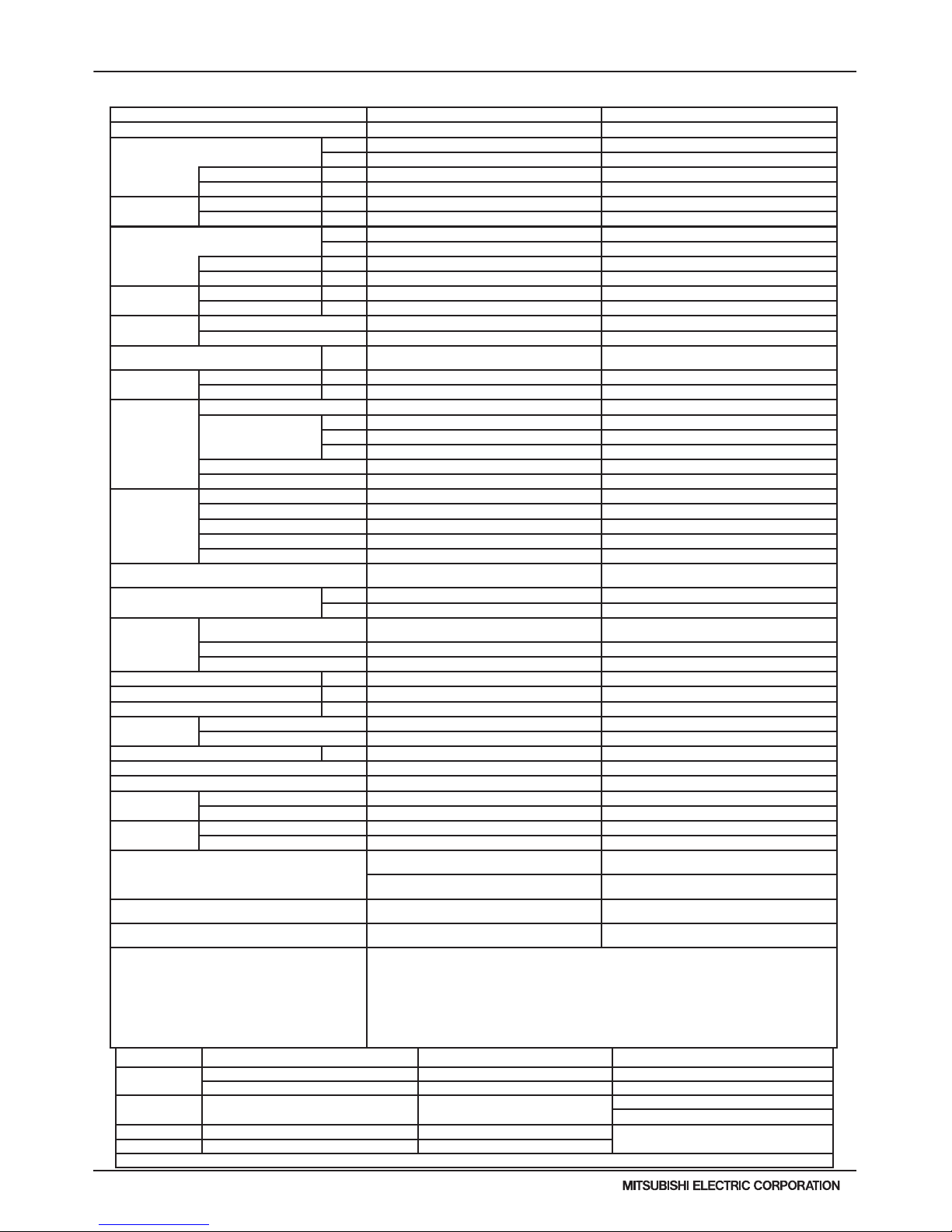
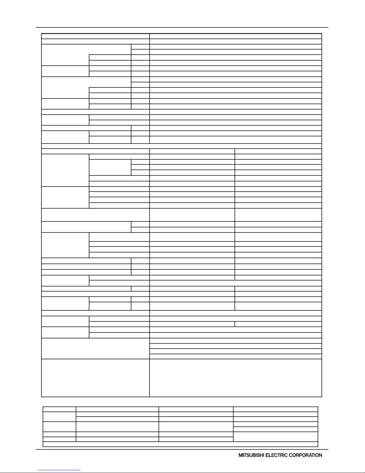
1. SPECIFICATIONS
Model
PURY-HP72TKMU-A-H PURY-HP96TKMU-A-H
Power source
3-phase 3-wire 208 / 230V ±10% 60Hz 3-phase 3-wire 208 / 230V ±10% 60Hz
Cooling capacity (Nominal) *1 (208 / 230V)
Btu/h
72,000 96,000
kW
21.1 28.1
Power input kW
5.08 *4 7.66 *4
Current input A
15.6 / 14.1 *4 23.6 / 21.3 *4
Temp. range of
cooling *3
Indoor W.B.
59 ~ 75° F(15 ~ 24° C) 59 ~ 75° F(15 ~ 24° C)
Outdoor D.B.
23 ~ 115° F (-5 ~ +46° C) *5 23 ~ 115° F (-5 ~ +46° C) *5
Heating capacity (Nominal) *2 (208-230V)
Btu/h
80,000 108,000
kW
23.4 31.7
Power input kW
6.26 *4 8.88 *4
Current input A
19.3 / 17.4 *4 27.3 / 24.7 *4
Temp. range of
heating *3
Indoor D.B.
59~81°F(15~27°C) 59~81°F(15~27°C)
Outdoor W.B.
-13~60°F(-25~15.5°C) -13~60°F(-25~15.5°C)
Indoor unit
Total capacity
50~150 % of outdoor unit capacity 50~150 % of outdoor unit capacity
Model / Quantity
P06~P96 / 1~18 P06~P96 / 1~24
Sound pressure level (measured in
anechoic room)
dB <A>
58.0 58.0
Refrigerant
piping diameter
Liquid (High Pressure) In. (mm)
5/8 (15.88) Brazed 3/4 (19.05) Brazed
Gas (Low Pressure) In. (mm)
3/4 (19.05) Brazed 7/8 (22.2) Brazed
Fan
Type x Quantity
Propeller fan x 1 Propeller fan x 1
Airow rate
CFM
6,200 6,200
m3 / min
175 175
L/s
2,920 2,920
Control, Driving mechanism
Inverter-control, Brushless DC motor Inverter-control, Brushless DC motor
External static pressure *6
0 in.WG (0 Pa) *6 0 in.WG (0 Pa) *6
Compressor
Type x Quantity
Inverter scroll hermetic compressor x 1 Inverter scroll hermetic compressor x 1
Manufacturer
AC&R Works, MITSUBISHI ELECTRIC CORP. AC&R Works, MITSUBISHI ELECTRIC CORP.
Operating Range
Heating: 16-100%
Heating: 13-100%
Starting method
Inverter Inverter
Lubricant
MEL32 MEL32
External nish
Pre-coated galvanized steel sheet
<MUNSELL 5Y 8/1 or similar>
Pre-coated galvanized steel sheet
<MUNSELL 5Y 8/1 or similar>
External dimension H x W x D
In.
64-31/32 x 48-1/16 x 29-15/16 64-31/32 x 48-1/16 x 29-15/16
mm
1,650 x 1,220 x 760 1,650 x 1,220 x 760
Protection
devices
High pressure protection
High pressure sensor, High pressure switch at
4.15MPa (601 psi)
High pressure sensor, High pressure switch at
4.15MPa (601 psi)
Inverter circuit (COMP. / FAN)
Over-current protection Over-current protection
Fan motor
Thermal switch Thermal switch
Minimum Circuit Ampacity (MCA) A 44 / 40 60 / 54
Recommended Fuse/Breaker Size A 50 65
Maximum Fuse Size A 60 80
Refrigerant
Type x original charge
R410A x 26 lbs + 1 oz (11.8 kg) R410A x 26 lbs + 1 oz (11.8kg)
Control
Indoor LEV and BC controller Indoor LEV and BC controller
Net weight lbs (kg)
552 (250) 552 (250)
Heat exchanger
Salt-resistant cross n & copper tube Salt-resistant cross n & copper tube
Defrost method
Auto-defrost mode (Reversed refrigerant cycle) Auto-defrost mode (Reversed refrigerant cycle)
Drawing
External
KJ94G386 KJ94G386
Wiring
KE94C883 KE94C883
Standard
attachment
Document
Installation Manual Installation Manual
Accessory
Details refer to External Drw Details refer to External Drw
Optional parts
Joint: CMY-Y102SS-G2,CMY-Y102LS-G2,
CMY-R160C-J
Joint: CMY-Y102SS-G2,CMY-Y102LS-G2,
CMY-R160C-J
BC controller: CMB-P104,105,106,108,1010,1013,
1016NU-G
BC controller: CMB-P104,105,106,108,1010,1013,
1016NU-G
Main BC controller: CMB-P108,1010,1013,
1016NU-GA,1016NU-HA
Main BC controller: CMB-P108,1010,1013,
1016NU-GA,1016NU-HA
Sub BC controller: CMB-P104,108NU-GB,
CMB-P1016NU-HB
Sub BC controller: CMB-P104,108NU-GB,
CMB-P1016NU-HB
Remark
Details on foundation work, duct work, insulation work, electrical wiring, power source switch, and
other items shall be referred to the Installation Manual.
*3 Harsh weather environments may demand performance enhancing equipment.
Ask your Mitsubishi Electric representative for more details on your region.
*4 For details on the electrical data needed for installing these units,
see the H2i R2-Series System Design section.
*5 For details on extended ambient cooling operation range down to -10°FDB (-23°CDB),
see Low Ambient Cooling Kit information.
*6 External static pressure is adjustable via dipswitch setting
(0.12 in.WG, 0.24 in.WG / 30Pa, 60Pa).
Note: *1 Nominal cooling conditions *2 Nominal heating conditions
Unit converter
Indoor:
80degF D.B./ 67degF W.B. 70degF D.B.
kcal =kW x 860
(26.7degC D.B./ 19.4degC W.B.) (21.1degC D.B.)
BTU/h =kW x 3,412
Outdoor: 95degF D.B. (35degC D.B.)
47degF D.B./ 43degF W.B.
(8.3degC D.B./ 6.1degC W.B.)
cfm =m3/min x 35.31
lb =kg / 0.4536
Pipe length: 25ft.(7.6m) 25ft.(7.6m)
* Above specification data is subject to rounding
variation.
Level difference: 0ft.(0m) 0ft.(0m)
* Due to continuing improvement, above specifications may be subject to change without notice.
1-1. PURY-HP72~192T(S)KMU-A-H Specications
Page 5
PURY-HP-T(S)KMU,-Y(S)KMU (September 2014)
H2i-R2-5
© 2014 Mitsubishi Electric US, Inc.
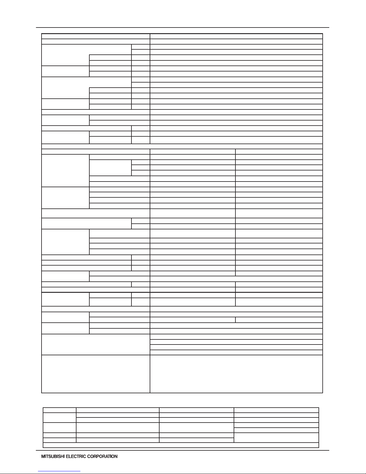
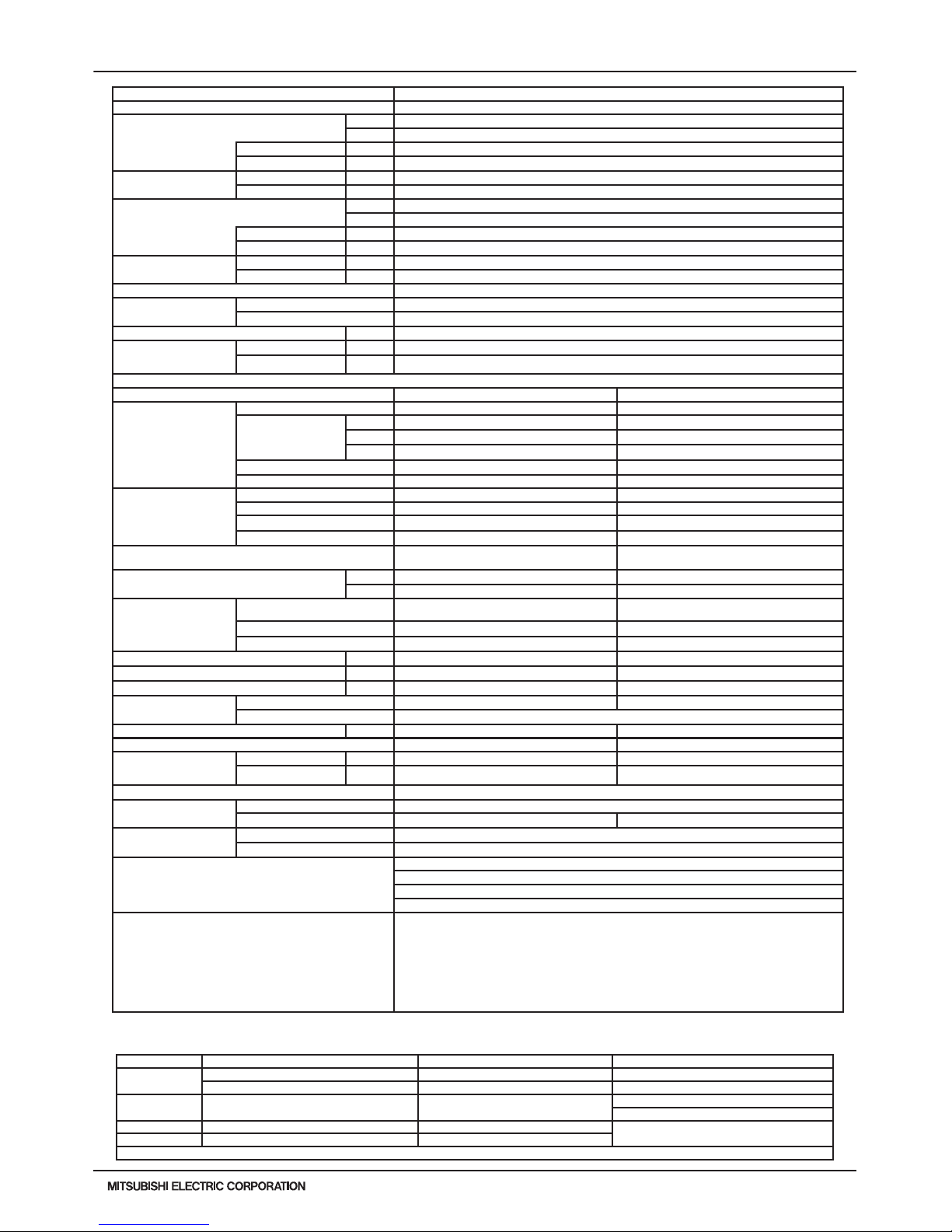
1. SPECIFICATIONS
Model PURY-HP144TSKMU-A-H
Power source 3-phase 3-wire 208 / 230V ±10% 60Hz
Cooling capacity (Nominal) *1 (208 / 230V)
Btu/h 144,000
kW 42.2
Power input
kW 10.85 *4
Current input
A 33.4 / 30.2 *4
Temp. range of cooling *3
Indoor
W.B. 59 ~ 75° F(15 ~ 24° C)
Outdoor
D.B. 23 ~ 115° F (-5 ~ +46° C) *5
Heating capacity (Nominal) *2 (208-230V)
Btu/h 160,000
kW 46.9
Power input
kW 13.16 *4
Current input
A 40.5 / 36.7 *4
Temp. range of heating *3
Indoor
D.B. 59~81°F(15~27°C)
Outdoor
W.B. -13~60°F(-25~15.5°C)
System Compressor Operating Range Heating: 8-100%
Indoor unit
connectable
Total capacity 50~150 % of outdoor unit capacity
Model / Quantity P06~P96 / 1~36
Sound pressure level (measured in anechoic room) dB <A> 61.0
Refrigerant piping
diameter from Twinning
Kit to Indoor Units
Liquid (High Pressure) In. (mm) 7/8 (22.2) Brazed
Gas (Low Pressure) In. (mm) 1-1/8 (28.58) Brazed
Set Model
Model PURY-HP72TKMU-A-H PURY-HP72TKMU-A-H
Fan
Type x Quantity Propeller fan x 1 Propeller fan x 1
Airflow rate
CFM 6,200 6,200
m3 / min 175 175
L/s 2,920 2,920
Control , Driving mechanism Inverter-control, Brushless DC motor Inverter-control, Brushless DC motor
External static pressure *6 0 in.WG (0 Pa) *6 0 in.WG (0 Pa) *6
Compressor
Type x Quantity Inverter scroll hermetic compressor x 1 Inverter scroll hermetic compressor x 1
Manufacturer AC&R Works, MITSUBISHI ELECTRIC CORP. AC&R Works, MITSUBISHI ELECTRIC CORP.
Starting method Inverter Inverter
Lubricant MEL32 MEL32
External finish
Pre-coated galvanized steel sheet
<MUNSELL 5Y 8/1 or similar>
Pre-coated galvanized steel sheet
<MUNSELL 5Y 8/1 or similar>
External dimension H x W x D
In. 64-31/32 x 48-1/16 x 29-15/16 64-31/32 x 48-1/16 x 29-15/16
mm 1,650 x 1,220 x 760 1,650 x 1,220 x 760
Protection
devices
High pressure protection
High pressure sensor, High pressure switch at
4.15MPa (601 psi)
High pressure sensor, High pressure switch at
4.15MPa (601 psi)
Inverter circuit (COMP. / FAN)
Over-heat protection,Over-current protection Over-heat protection,Over-current protection
Compressor Over-heat protection Over-heat protection
Fan Motor Thermal switch Thermal switch
Minimum Circuit Ampacity (MCA) A 44 / 40 44 / 40
Recommended Fuse/Breaker Size A 50 50
Maximum Fuse Size A 60 60
Refrigerant
Type x original charge R410A x 26 lbs + 1 oz (11.8 kg) R410A x 26 lbs + 1 oz (11.8 kg)
Control LEV and HIC circuit
Net weight lbs (kg) 552 (250) 552 (250)
Heat exchanger Salt-resistant cross n & copper tube Salt-resistant cross n & copper tube
Refrigerant piping
diameter from Module to
Twinning Kit
Liquid (High Pressure) In. (mm) 5/8”(15.88)Brazed 5/8”(15.88)Brazed
Gas (Low Pressure) In. (mm) 3/4”(19.05)Brazed 3/4”(19.05)Brazed
Defrosting method Auto-defrost mode (Reversed refrigerant cycle)
Drawing
External KJ94G492
Wiring KE94C883 KE94C883
Standard attachment
Document Installation Manual
Accessory Details refer to External Drw
Optional parts
Outdoor Twinning kit: CMY-Y100CBK2
Joint: CMY-Y102SS-G2,CMY-Y102LS-G2,CMY-Y202S-G2,CMY-R160C-J
Main BC controller: CMB-P108,1010,1013,1016NU-GA,1016NU-HA
Sub BC controller: CMB-P104,108NU-GB,CMB-P1016NU-HB
Remark
Details on foundation work, duct work, insulation work, electrical wiring, power source switch, and
other items shall be referred to the Installation Manual.
*3 Harsh weather environments may demand performance enhancing equipment.
Ask your Mitsubishi Electric representative for more details on your region.
*4 For details on the electrical data needed for installing these units,
see the H2i R2-Series System Design section.
*5 For details on extended ambient cooling operation range down to -10°FDB (-23°CDB),
see Low Ambient Cooling Kit information.
*6 External static pressure is adjustable via dipswitch setting
(0.12 in.WG, 0.24 in.WG / 30Pa, 60Pa).
Note: *1 Nominal cooling conditions *2 Nominal heating conditions Unit converter
Indoor:
80degF D.B./ 67degF W.B. 70degF D.B. kcal =kW x 860
(26.7degC D.B./ 19.4degC W.B.) (21.1degC D.B.) BTU/h =kW x 3,412
Outdoor: 95degF D.B. (35degC D.B.)
47degF D.B./ 43degF W.B.
(8.3degC D.B./ 6.1degC W.B.)
cfm =m3/min x 35.31
lb =kg / 0.4536
Pipe length: 25ft.(7.6m) 25ft.(7.6m)
* Above specification data is subject to rounding
variation.
Level difference: 0ft.(0m) 0ft.(0m)
* Due to continuing improvement, above specifications may be subject to change without notice.
Page 6
H2i-R2-6
PURY-HP-T(S)KMU,-Y(S)KMU (September 2014)
© 2014 Mitsubishi Electric US, Inc.
1. SPECIFICATIONS
Model
PURY-HP192TSKMU-A-H
Power source
3-phase 3-wire 208 / 230V ±10% 60Hz
Cooling capacity (Nominal) *1 (208 / 230V)
Btu/h
192,000
kW
56.3
Power input kW
15.86 *4
Current input A
48.9 / 44.2 *4
Temp. range of cooling *3
Indoor W.B.
59 ~ 75° F(15 ~ 24° C)
Outdoor D.B.
23 ~ 115° F (-5 ~ +46° C) *5
Heating capacity (Nominal) *2 (208-230V)
Btu/h
215,000
kW
63.0
Power input kW
18.52 *4
Current input A
55.9 / 50.5 *4
Temp. range of heating *3
Indoor D.B.
59~81°F(15~27°C)
Outdoor W.B.
-13~60°F(-25~15.5°C)
System Compressor Operating Range
Heating: 6-100%
Indoor unit
connectable
Total capacity
50~150 % of outdoor unit capacity
Model / Quantity
P06~P96 / 1-48
Sound pressure level (measured in anechoic room) dB <A>
61.0
Refrigerant piping diameter
from Twinning Kit to Indoor
Units
Liquid (High Pressure) In. (mm)
7/8”(22.2) Brazed
Gas (Low Pressure) In. (mm)
1-1/8”(28.58) Brazed
Set Model
Model
PURY-HP96TKMU-A-H PURY-HP96TKMU-A-H
Fan
Type x Quantity
Propeller fan x 1 Propeller fan x 1
Airow rate
CFM
6,200 6,200
m3 / min
175 175
L/s
2,920 2,920
Control , Driving mechanism
Inverter-control, Brushless DC motor Inverter-control, Brushless DC motor
External static pressure *6
0 in.WG (0 Pa) *6 0 in.WG (0 Pa) *6
Compressor
Type x Quantity
Inverter scroll hermetic compressor x 1 Inverter scroll hermetic compressor x 1
Manufacturer
AC&R Works, MITSUBISHI ELECTRIC CORP. AC&R Works, MITSUBISHI ELECTRIC CORP.
Starting method
Inverter Inverter
Lubricant
MEL32 MEL32
External nish
Pre-coated galvanized steel sheet
<MUNSELL 5Y 8/1 or similar>
Pre-coated galvanized steel sheet
<MUNSELL 5Y 8/1 or similar>
External dimension H x W x D
In.
64-31/32 x 48-1/16 x 29-15/16 64-31/32 x 48-1/16 x 29-15/16
mm
1,650 x 1,220 x 760 1,650 x 1,220 x 760
Protection
devices
High pressure protection
High pressure sensor, High pressure switch at
4.15MPa (601 psi)
High pressure sensor, High pressure switch at
4.15MPa (601 psi)
Inverter circuit (COMP. / FAN)
Over-current protection Over-current protection
Fan Motor
Thermal switch Thermal switch
Minimum Circuit Ampacity (MCA) A
60 / 54 60 / 54
Recommended Fuse/Breaker Size A
65 65
Maximum Fuse Size A
80 80
Refrigerant
Type x original charge
R410A x 26 lbs + 1oz (11.8kg) R410A x 26 lbs + 1oz (11.8kg)
Control
LEV and HIC circuit
Net weight lbs (kg)
552 (250) 552 (250)
Heat exchanger
Salt-resistant cross n & copper tube Salt-resistant cross n & copper tube
Refrigerant piping diameter
from Module to Twinning Kit
Liquid (High Pressure) In. (mm)
3/4”(19.05)Brazed 3/4”(19.05)Brazed
Gas (Low Pressure) In. (mm)
7/8”(22.2)Brazed 7/8”(22.2)Brazed
Defrosting method
Auto-defrost mode (Reversed refrigerant cycle)
Drawing
External
KJ94G492
Wiring
KE94C883 KE94C883
Standard attachment
Document
Installation Manual
Accessory
Details refer to External Drw
Optional parts
Outdoor Twinning kit: CMY-Y100CBK2
Joint: CMY-Y102SS-G2,CMY-Y102LS-G2,CMY-Y202S-G2,CMY-R160C-J
Main BC controller: CMB-P108,1010,1013,1016NU-GA,1016NU-HA
Sub BC controller: CMB-P104,108NU-GB,CMB-P1016NU-HB
Remark
Details on foundation work, duct work, insulation work, electrical wiring, power source switch, and
other items shall be referred to the Installation Manual.
*3 Harsh weather environments may demand performance enhancing equipment.
Ask your Mitsubishi Electric representative for more details on your region.
*4 For details on the electrical data needed for installing these units,
see the H2i R2-Series System Design section.
*5 For details on extended ambient cooling operation range down to -10°FDB (-23°CDB),
see Low Ambient Cooling Kit information.
*6 External static pressure is adjustable via dipswitch setting
(0.12 in.WG, 0.24 in.WG / 30Pa, 60Pa).
Note: *1 Nominal cooling conditions *2 Nominal heating conditions Unit converter
Indoor:
80degF D.B./ 67degF W.B. 70degF D.B. kcal =kW x 860
(26.7degC D.B./ 19.4degC W.B.) (21.1degC D.B.) BTU/h =kW x 3,412
Outdoor: 95degF D.B. (35degC D.B.)
47degF D.B./ 43degF W.B.
(8.3degC D.B./ 6.1degC W.B.)
cfm =m3/min x 35.31
lb =kg / 0.4536
Pipe length: 25ft.(7.6m) 25ft.(7.6m)
* Above specification data is subject to rounding
variation.
Level difference: 0ft.(0m) 0ft.(0m)
* Due to continuing improvement, above specifications may be subject to change without notice.
Page 7
PURY-HP-T(S)KMU,-Y(S)KMU (September 2014)
H2i-R2-7
© 2014 Mitsubishi Electric US, Inc.
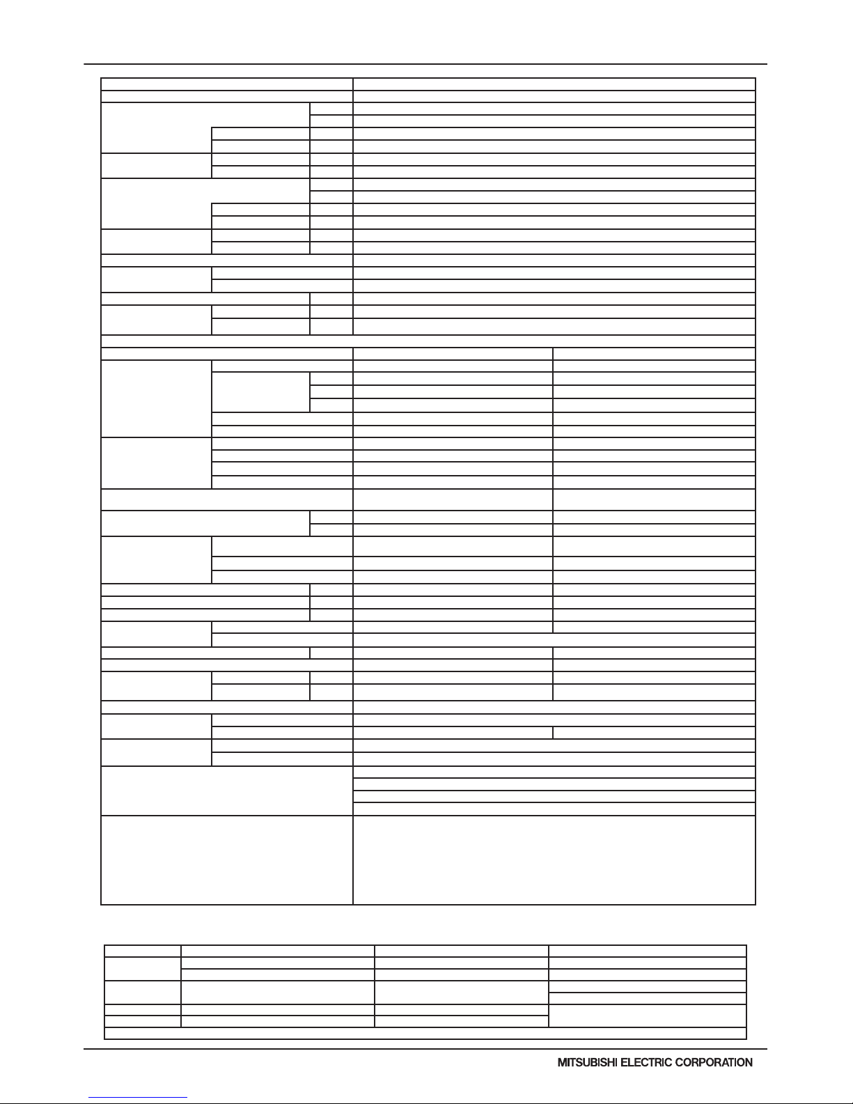
1. SPECIFICATIONS
Model
PURY-HP72YKMU-A PURY-HP96YKMU-A
Power source
3-phase 3-wire 460V ±10% 60Hz 3-phase 3-wire 460V ±10% 60Hz
Cooling capacity (Nominal) *1 (460V)
Btu/h
72,000 96,000
kW
21.1 28.1
Power input kW
5.08 *4 7.66 *4
Current input A
7.0 *4 10.6 *4
Temp. range of
cooling *3
Indoor W.B.
59 ~ 75° F(15 ~ 24° C) 59 ~ 75° F(15 ~ 24° C)
Outdoor D.B.
23 ~ 115° F (-5 ~ +46° C) *5 23 ~ 115° F (-5 ~ +46° C) *5
Heating capacity (Nominal) *2 (460V)
Btu/h
80,000 108,000
kW
23.4 31.7
Power input kW
6.26 *4 8.88 *4
Current input A
8.7 *4 12.3 *4
Temp. range of
heating *3
Indoor D.B.
59~81°F(15~27°C) 59~81°F(15~27°C)
Outdoor W.B.
-13~60°F(-25~15.5°C) -13~60°F(-25~15.5°C)
Indoor unit
Total capacity
50~150 % of outdoor unit capacity 50~150 % of outdoor unit capacity
Model / Quantity
P06~P96 / 1~18 P06~P96 / 1~24
Sound pressure level (measured in
anechoic room)
dB <A>
58.0 58.0
Refrigerant
piping diameter
Liquid (High Pressure) In. (mm)
5/8 (15.88) Brazed 3/4 (19.05) Brazed
Gas (Low Pressure) In. (mm)
3/4 (19.05) Brazed 7/8 (22.2) Brazed
Fan
Type x Quantity
Propeller fan x 1 Propeller fan x 1
Airow rate
CFM
6,200 6,200
m3 / min
175 175
L/s
2,920 2,920
Control, Driving mechanism
Inverter-control, Brushless DC motor Inverter-control, Brushless DC motor
External static pressure *6
0 in.WG (0 Pa) *6 0 in.WG (0 Pa) *6
Compressor
Type x Quantity
Inverter scroll hermetic compressor x 1 Inverter scroll hermetic compressor x 1
Manufacturer
AC&R Works, MITSUBISHI ELECTRIC CORP. AC&R Works, MITSUBISHI ELECTRIC CORP.
Operating Range
Heating: 16-100%
Heating: 13-100%
Starting method
Inverter Inverter
Lubricant
MEL32 MEL32
External nish
Pre-coated galvanized steel sheet
<MUNSELL 5Y 8/1 or similar>
Pre-coated galvanized steel sheet
<MUNSELL 5Y 8/1 or similar>
External dimension H x W x D
In.
64-31/32 x 48-1/16 x 29-15/16 64-31/32 x 48-1/16 x 29-15/16
mm
1,650 x 1,220 x 760 1,650 x 1,220 x 760
Protection
devices
High pressure protection
High pressure sensor, High pressure switch at
4.15MPa (601 psi)
High pressure sensor, High pressure switch at
4.15MPa (601 psi)
Inverter circuit (COMP. / FAN)
Over-current protection Over-current protection
Fan motor
Thermal switch Thermal switch
Minimum Circuit Ampacity (MCA) A 26 32
Recommended Fuse/Breaker Size A 30 35
Maximum Fuse Size A 30 35
Refrigerant
Type x original charge
R410A x 26 lbs + 1 oz (11.8 kg) R410A x 26 lbs + 1 oz (11.8kg)
Control
Indoor LEV and BC controller Indoor LEV and BC controller
Net weight lbs (kg)
574 (260) 576 (261)
Heat exchanger
Salt-resistant cross n & copper tube Salt-resistant cross n & copper tube
Defrost method
Auto-defrost mode (Reversed refrigerant cycle) Auto-defrost mode (Reversed refrigerant cycle)
Drawing
External
KJ94G387 KJ94G387
Wiring
KE94C884 KE94C884
Standard
attachment
Document
Installation Manual Installation Manual
Accessory
Details refer to External Drw Details refer to External Drw
Optional parts
Joint: CMY-Y102SS-G2,CMY-Y102LS-G2,
CMY-R160C-J
Joint: CMY-Y102SS-G2,CMY-Y102LS-G2,
CMY-R160C-J
BC controller: CMB-P104,105,106,108,1010,1013,
1016NU-G
BC controller: CMB-P104,105,106,108,1010,1013,
1016NU-G
Main BC controller: CMB-P108,1010,1013,
1016NU-GA,1016NU-HA
Main BC controller: CMB-P108,1010,1013,
1016NU-GA,1016NU-HA
Sub BC controller: CMB-P104,108NU-GB,
CMB-P1016NU-HB
Sub BC controller: CMB-P104,108NU-GB,
CMB-P1016NU-HB
Remark
Details on foundation work, duct work, insulation work, electrical wiring, power source switch, and
other items shall be referred to the Installation Manual.
*3 Harsh weather environments may demand performance enhancing equipment.
Ask your Mitsubishi Electric representative for more details on your region.
*4 For details on the electrical data needed for installing these units,
see the H2i R2-Series System Design section.
*5 For details on extended ambient cooling operation range down to -10°FDB (-23°CDB),
see Low Ambient Cooling Kit information.
*6 External static pressure is adjustable via dipswitch setting
(0.12 in.WG, 0.24 in.WG / 30Pa, 60Pa).
Note: *1 Nominal cooling conditions *2 Nominal heating conditions
Unit converter
Indoor:
80degF D.B./ 67degF W.B. 70degF D.B.
kcal =kW x 860
(26.7degC D.B./ 19.4degC W.B.) (21.1degC D.B.)
BTU/h =kW x 3,412
Outdoor: 95degF D.B. (35degC D.B.)
47degF D.B./ 43degF W.B.
(8.3degC D.B./ 6.1degC W.B.)
cfm =m3/min x 35.31
lb =kg / 0.4536
Pipe length: 25ft.(7.6m) 25ft.(7.6m)
* Above specification data is subject to rounding
variation.
Level difference: 0ft.(0m) 0ft.(0m)
* Due to continuing improvement, above specifications may be subject to change without notice.
1-2. PURY-HP72~192Y(S)KMU-A Specications
Page 8
H2i-R2-8
PURY-HP-T(S)KMU,-Y(S)KMU (September 2014)
© 2014 Mitsubishi Electric US, Inc.
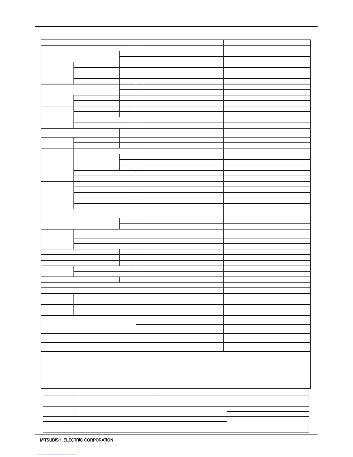
1. SPECIFICATIONS
Model PURY-HP144YSKMU-A
Power source 3-phase 3-wire 460V ±10% 60Hz
Cooling capacity (Nominal) *1 (460V)
Btu/h 144,000
kW 42.2
Power input
kW 10.85 *4
Current input
A 15.1 *4
Temp. range of cooling *3
Indoor
W.B. 59 ~ 75° F(15 ~ 24° C)
Outdoor
D.B. 23 ~ 115° F (-5 ~ +46° C) *5
Heating capacity (Nominal) *2 (460V)
Btu/h 160,000
kW 46.9
Power input
kW 13.16 *4
Current input
A 18.3 *4
Temp. range of heating *3
Indoor
D.B. 59~81°F(15~27°C)
Outdoor
W.B. -13~60°F(-25~15.5°C)
System Compressor Operating Range Heating: 8-100%
Indoor unit
connectable
Total capacity 50~150 % of outdoor unit capacity
Model / Quantity P06~P96 / 1~36
Sound pressure level (measured in anechoic room) dB <A> 61.0
Refrigerant piping
diameter from Twinning
Kit to Indoor Units
Liquid (High Pressure) In. (mm) 7/8 (22.2) Brazed
Gas (Low Pressure) In. (mm) 1-1/8 (28.58) Brazed
Set Model
Model PURY-HP72YKMU-A PURY-HP72YKMU-A
Fan
Type x Quantity Propeller fan x 1 Propeller fan x 1
Airflow rate
CFM 6,200 6,200
m3 / min 175 175
L/s 2,920 2,920
Control , Driving mechanism Inverter-control, Brushless DC motor Inverter-control, Brushless DC motor
External static pressure *6 0 in.WG (0 Pa) *6 0 in.WG (0 Pa) *6
Compressor
Type x Quantity Inverter scroll hermetic compressor x 1 Inverter scroll hermetic compressor x 1
Manufacturer AC&R Works, MITSUBISHI ELECTRIC CORP. AC&R Works, MITSUBISHI ELECTRIC CORP.
Starting method Inverter Inverter
Lubricant MEL32 MEL32
External finish
Pre-coated galvanized steel sheet
<MUNSELL 5Y 8/1 or similar>
Pre-coated galvanized steel sheet
<MUNSELL 5Y 8/1 or similar>
External dimension H x W x D
In. 64-31/32 x 48-1/16 x 29-15/16 64-31/32 x 48-1/16 x 29-15/16
mm 1,650 x 1,220 x 760 1,650 x 1,220 x 760
Protection
devices
High pressure protection
High pressure sensor, High pressure switch at
4.15MPa (601 psi)
High pressure sensor, High pressure switch at
4.15MPa (601 psi)
Inverter circuit (COMP. / FAN)
Over-heat protection,Over-current protection Over-heat protection,Over-current protection
Compressor Over-heat protection Over-heat protection
Fan Motor Thermal switch Thermal switch
Minimum Circuit Ampacity (MCA) A
26 26
Recommended Fuse/Breaker Size A
30 30
Maximum Fuse Size A
30 30
Refrigerant
Type x original charge R410A x 26 lbs + 1 oz (11.8 kg) R410A x 26 lbs + 1 oz (11.8 kg)
Control LEV and HIC circuit
Net weight lbs (kg) 574 (260) 574 (260)
Heat exchanger Salt-resistant cross n & copper tube Salt-resistant cross n & copper tube
Refrigerant piping
diameter from Module to
Twinning Kit
Liquid (High Pressure) In. (mm) 5/8 (15.88)Brazed 5/8 (15.88)Brazed
Gas (Low Pressure) In. (mm) 3/4 (19.05)Brazed 3/4 (19.05)Brazed
Defrosting method Auto-defrost mode (Reversed refrigerant cycle)
Drawing
External KJ94G493
Wiring KE94C884 KE94C884
Standard attachment
Document Installation Manual
Accessory Details refer to External Drw
Optional parts
Outdoor Twinning kit: CMY-Y100CBK2
Joint: CMY-Y102SS-G2,CMY-Y102LS-G2,CMY-Y202S-G2,CMY-R160C-J
Main BC controller: CMB-P108,1010,1013,1016NU-GA,1016NU-HA
Sub BC controller: CMB-P104,108NU-GB,CMB-P1016NU-HB
Remark
Details on foundation work, duct work, insulation work, electrical wiring, power source switch, and
other items shall be referred to the Installation Manual.
*3 Harsh weather environments may demand performance enhancing equipment.
Ask your Mitsubishi Electric representative for more details on your region.
*4 For details on the electrical data needed for installing these units,
see the H2i R2-Series System Design section.
*5 For details on extended ambient cooling operation range down to -10°FDB (-23°CDB),
see Low Ambient Cooling Kit information.
*6 External static pressure is adjustable via dipswitch setting
(0.12 in.WG, 0.24 in.WG / 30Pa, 60Pa).
Note: *1 Nominal cooling conditions *2 Nominal heating conditions Unit converter
Indoor:
80degF D.B./ 67degF W.B. 70degF D.B. kcal =kW x 860
(26.7degC D.B./ 19.4degC W.B.) (21.1degC D.B.) BTU/h =kW x 3,412
Outdoor: 95degF D.B. (35degC D.B.)
47degF D.B./ 43degF W.B.
(8.3degC D.B./ 6.1degC W.B.)
cfm =m3/min x 35.31
lb =kg / 0.4536
Pipe length: 25ft.(7.6m) 25ft.(7.6m)
* Above specification data is subject to rounding
variation.
Level difference: 0ft.(0m) 0ft.(0m)
* Due to continuing improvement, above specifications may be subject to change without notice.
Page 9
PURY-HP-T(S)KMU,-Y(S)KMU (September 2014)
H2i-R2-9
© 2014 Mitsubishi Electric US, Inc.
1. SPECIFICATIONS
Model
PURY-HP192YSKMU-A
Power source
3-phase 3-wire 460V ±10% 60Hz
Cooling capacity (Nominal) *1 (460V)
Btu/h
192,000
kW
56.3
Power input kW
15.86 *4
Current input A
22.1 *4
Temp. range of cooling *3
Indoor W.B.
59 ~ 75° F(15 ~ 24° C)
Outdoor D.B.
23 ~ 115° F (-5 ~ +46° C) *5
Heating capacity (Nominal) *2 (460V)
Btu/h
215,000
kW
63.0
Power input kW
18.52 *4
Current input A
25.8 *4
Temp. range of heating *3
Indoor D.B.
59~81°F(15~27°C)
Outdoor W.B.
-13~60°F(-25~15.5°C)
System Compressor Operating Range
Heating: 6-100%
Indoor unit
connectable
Total capacity
50~150 % of outdoor unit capacity
Model / Quantity
P06~P96 / 1-48
Sound pressure level (measured in anechoic room) dB <A>
61.0
Refrigerant piping diameter
from Twinning Kit to Indoor
Units
Liquid (High Pressure) In. (mm)
7/8 (22.2) Brazed
Gas (Low Pressure) In. (mm)
1-1/8 (28.58) Brazed
Set Model
Model
PURY-HP96YKMU-A PURY-HP96YKMU-A
Fan
Type x Quantity
Propeller fan x 1 Propeller fan x 1
Airow rate
CFM
6,200 6,200
m3 / min
175 175
L/s
2,920 2,920
Control , Driving mechanism
Inverter-control, Brushless DC motor Inverter-control, Brushless DC motor
External static pressure *6
0 in.WG (0 Pa) *6 0 in.WG (0 Pa) *6
Compressor
Type x Quantity
Inverter scroll hermetic compressor x 1 Inverter scroll hermetic compressor x 1
Manufacturer
AC&R Works, MITSUBISHI ELECTRIC CORP. AC&R Works, MITSUBISHI ELECTRIC CORP.
Starting method
Inverter Inverter
Lubricant
MEL32 MEL32
External nish
Pre-coated galvanized steel sheet
<MUNSELL 5Y 8/1 or similar>
Pre-coated galvanized steel sheet
<MUNSELL 5Y 8/1 or similar>
External dimension H x W x D
In.
64-31/32 x 48-1/16 x 29-15/16 64-31/32 x 48-1/16 x 29-15/16
mm
1,650 x 1,220 x 760 1,650 x 1,220 x 760
Protection
devices
High pressure protection
High pressure sensor, High pressure switch at
4.15MPa (601 psi)
High pressure sensor, High pressure switch at
4.15MPa (601 psi)
Inverter circuit (COMP. / FAN)
Over-current protection Over-current protection
Fan Motor
Thermal switch Thermal switch
Minimum Circuit Ampacity (MCA) A 32 32
Recommended Fuse/Breaker Size A 35 35
Maximum Fuse Size A 35 35
Refrigerant
Type x original charge
R410A x 26 lbs + 1oz (11.8kg) R410A x 26 lbs + 1oz (11.8kg)
Control
LEV and HIC circuit
Net weight lbs (kg)
576 (261) 576 (261)
Heat exchanger
Salt-resistant cross n & copper tube Salt-resistant cross n & copper tube
Refrigerant piping diameter
from Module to Twinning Kit
Liquid (High Pressure) In. (mm)
3/4 (19.05)Brazed 3/4 (19.05)Brazed
Gas (Low Pressure) In. (mm)
7/8 (22.2)Brazed 7/8 (22.2)Brazed
Defrosting method
Auto-defrost mode (Reversed refrigerant cycle)
Drawing
External
KJ94G493
Wiring
KE94C884 KE94C884
Standard attachment
Document
Installation Manual
Accessory
Details refer to External Drw
Optional parts
Outdoor Twinning kit: CMY-Y100CBK2
Joint: CMY-Y102SS-G2,CMY-Y102LS-G2,CMY-Y202S-G2,CMY-R160C-J
Main BC controller: CMB-P108,1010,1013,1016NU-GA,1016NU-HA
Sub BC controller: CMB-P104,108NU-GB,CMB-P1016NU-HB
Remark
Details on foundation work, duct work, insulation work, electrical wiring, power source switch, and
other items shall be referred to the Installation Manual.
*3 Harsh weather environments may demand performance enhancing equipment.
Ask your Mitsubishi Electric representative for more details on your region.
*4 For details on the electrical data needed for installing these units,
see the H2i R2-Series System Design section.
*5 For details on extended ambient cooling operation range down to -10°FDB (-23°CDB),
see Low Ambient Cooling Kit information.
*6 External static pressure is adjustable via dipswitch setting
(0.12 in.WG, 0.24 in.WG / 30Pa, 60Pa).
Note: *1 Nominal cooling conditions *2 Nominal heating conditions Unit converter
Indoor:
80degF D.B./ 67degF W.B. 70degF D.B. kcal =kW x 860
(26.7degC D.B./ 19.4degC W.B.) (21.1degC D.B.) BTU/h =kW x 3,412
Outdoor: 95degF D.B. (35degC D.B.)
47degF D.B./ 43degF W.B.
(8.3degC D.B./ 6.1degC W.B.)
cfm =m3/min x 35.31
lb =kg / 0.4536
Pipe length: 25ft.(7.6m) 25ft.(7.6m)
* Above specification data is subject to rounding
variation.
Level difference: 0ft.(0m) 0ft.(0m)
* Due to continuing improvement, above specifications may be subject to change without notice.
Page 10
H2i-R2-10
PURY-HP-T(S)KMU,-Y(S)KMU (September 2014)
© 2014 Mitsubishi Electric US, Inc.
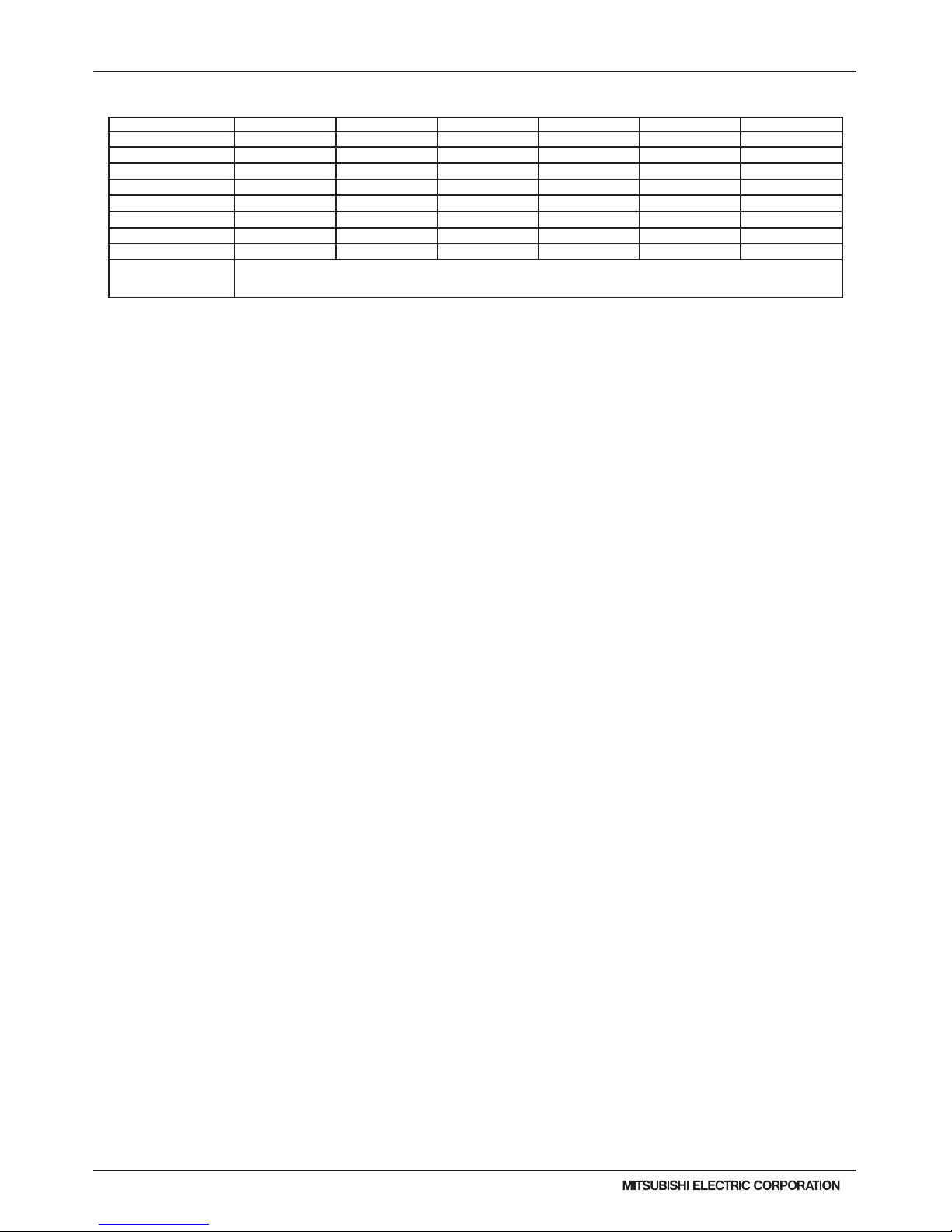
Model
IDU Type EER (95° F) *1 IEER *1 HI COP (47° F) *1 LOW COP (17° F) *1 SCHE
PURY-HP72TKMU-A-H Ducted / Non-Ducted 12.9 / 13 17.2 / 18.4 3.61 / 3.55 2.39 / 2.25 22.7 / 22.6
PURY-HP96TKMU-A-H Ducted / Non-Ducted 11.4 / 12.5 16.5 / 17.1 3.46 / 3.44 2.31 / 2.25 17.4 / 22.0
PURY-HP144TSKMU-A-H Ducted / Non-Ducted 12.5 / 12.6 16.7 / 17.9 3.47 / 3.41 2.32 / 2.05 22.1 / 22.0
PURY-HP192TSKMU-A-H Ducted / Non-Ducted 11.1 / 12.1 16.1 / 16.6 3.32 / 3.31 2.24 / 2.05 16.9 / 21.4
PURY-HP72YKMU-A Ducted / Non-Ducted 12.9 / 13 17.2 / 18.4 3.61 / 3.55 2.39 / 2.25 22.7 / 22.6
PURY-HP96YKMU-A Ducted / Non-Ducted 11.4 / 12.5 16.5 / 17.1 3.46 / 3.44 2.31 / 2.25 17.4 / 22.0
PURY-HP144YSKMU-A Ducted / Non-Ducted 12.5 / 12.6 16.7 / 17.9 3.47 / 3.41 2.32 / 2.05 22.1 / 22.0
PURY-HP192YSKMU-A Ducted / Non-Ducted 11.1 / 12.1 16.1 / 16.6 3.32 / 3.31 2.24 / 2.05 16.9 / 21.4
Note:
*1. Efficiency values based on AHRI 1230 test method.
1. SPECIFICATIONS
Efciency Ratings
Page 11
PURY-HP-T(S)KMU,-Y(S)KMU (September 2014)
H2i-R2-11
© 2014 Mitsubishi Electric US, Inc.
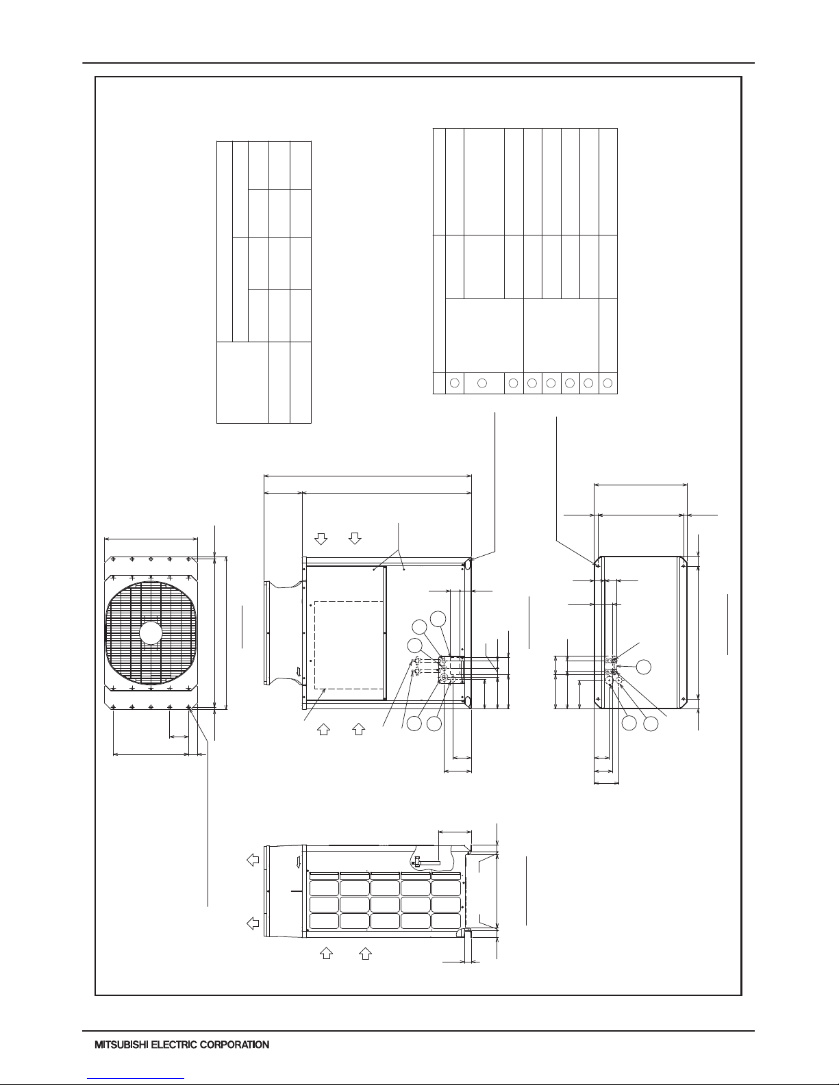
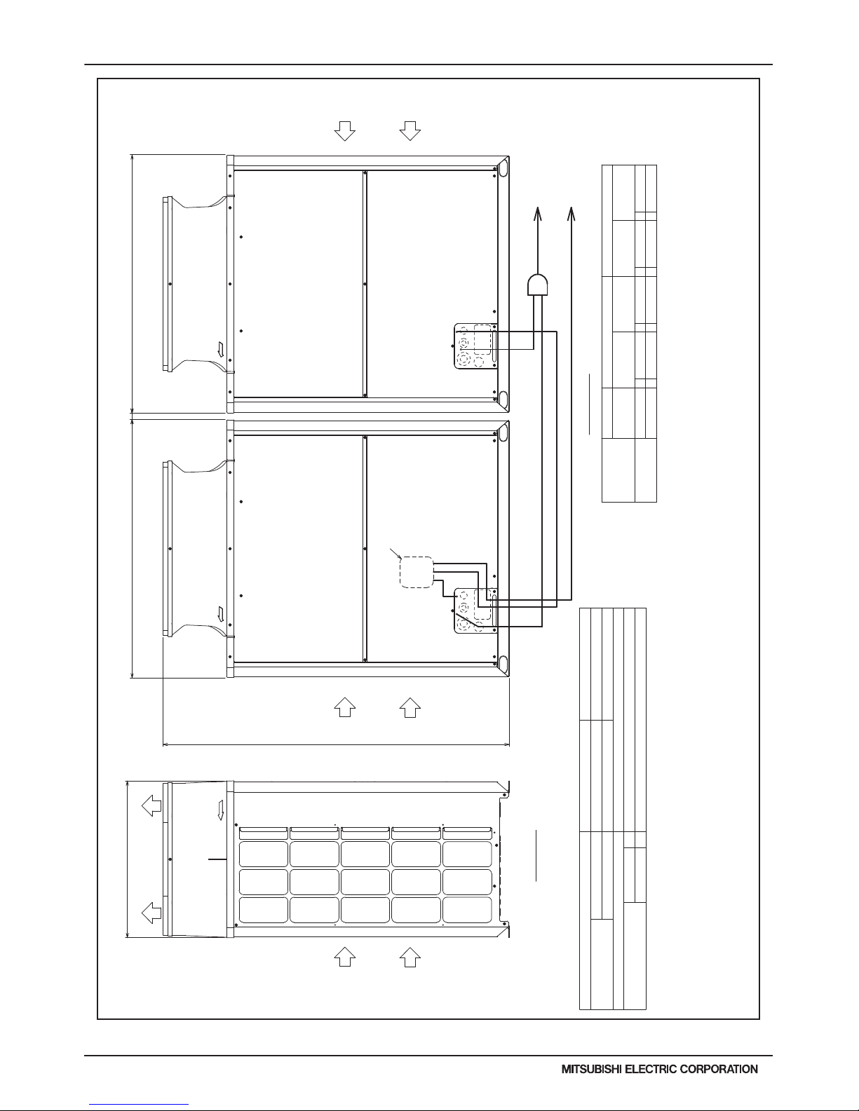
2. EXTERNAL DIMENSIONS
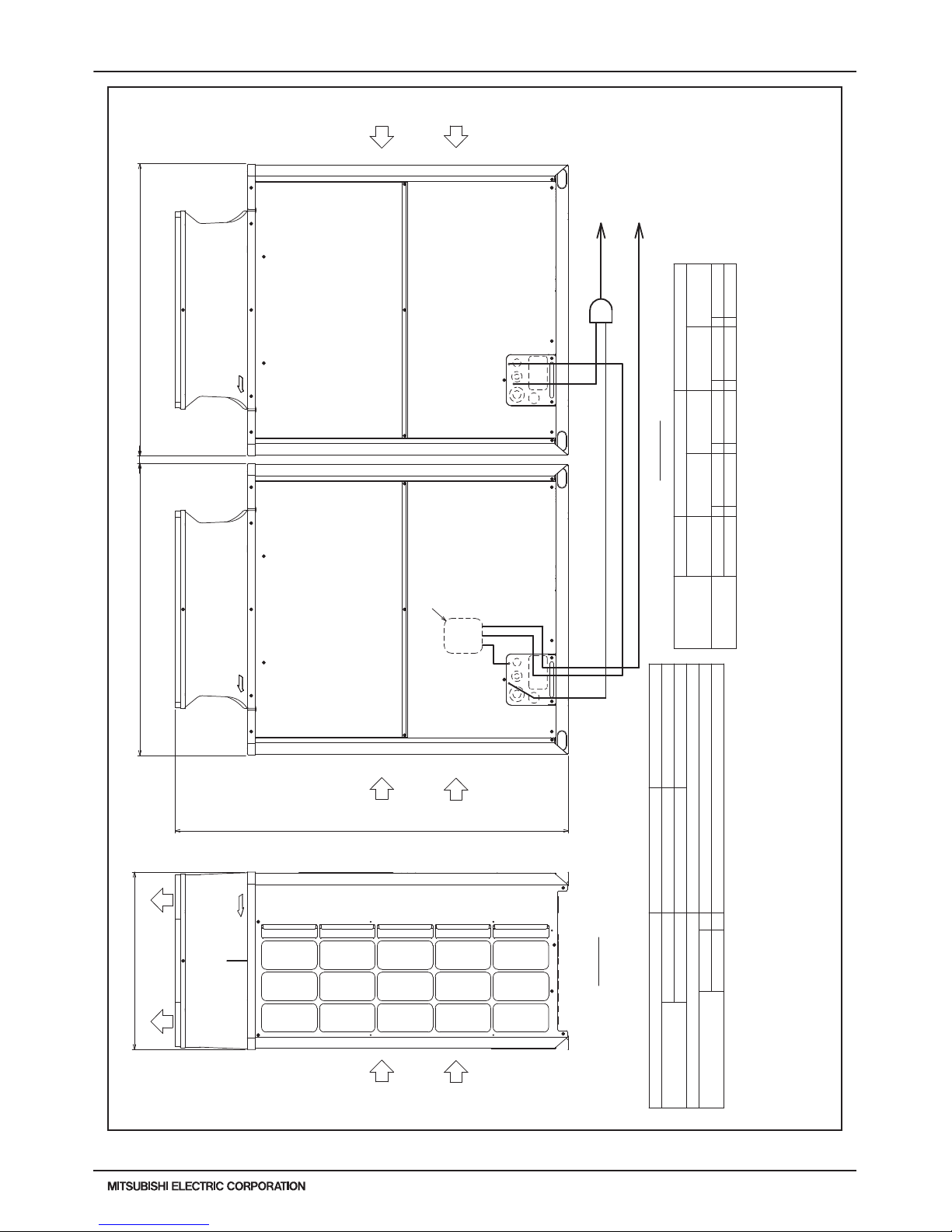
DATA U10
PURY-HP72, 96TKMU-A-H(-BS)
Unit : mm(in)
Refrigerant service
valve <High pressure>
Refrigerant service
valve <Low pressure>
Refrigerant service valve
<Low pressure>
Refrigerant service valve
<High pressure>
(5-3/4)
(5-3/4)
(1-3/16)
(1-3/16)
(Mounting pitch)
(26-23/32~26-15/16)
(26-13/16)
(Mounting pitch)
(3-5/32)
(3-5/32)
(4-25/32)
(8-9/16) 217
(5-23/32) 145
(10-11/32)
(7-23/32)
(3-5/16)
(3-23/32)
(10-23/32) 272
(11-7/8) 301
(8-15/16) 227
(2-1/4)
(2-1/4)
(13/16)
(13/16)
(3-17/32)
(3-1/16)
1
(9-29/32) 251
(9-5/16) 236
(10-23/32) 272
(11-15/16)
(25/32)(25/32)
(2-25/32)
=(5-29/32)X4
(23-5/8)
<Snow hood attachment hole>
4X5-ø4.6(3/16) Hole
(Make hole at the plastic fan guard
for snow hood attachment)
Intake
air
Discharge air
Control box
Intake
air
Service
panel
Intake
air
<Sling hole>
3
6
2
4
5
8
2X2-14(9/16)X20(13/16) Oval hole
2X2-80(3-5/32)X35(1-13/32) Oval hole
7
*1 Use the pipe joint(field supply) and connect to the refrigerant service
valve piping.
High
pressure
ø25.4
(1)
Low
pressure
Service valveRefrigerant pipe
Diameter
High
pressure
Low
pressure
Model
PURY-HP72TKMU-A-H(-BS)
ø25.4
(1)
ø19.05 Brazedø15.88 Brazed
ø45 Knockout hole
Specifications
ø43.7 or ø22.2 Knockout hole
ø62.7 or ø34.5 Knockout hole
Front through hole
Bottom through hole
Bottom through hole
Front through hole
Front through hole
For wires
Usage
Front through hole
Front through hole
(Uses when twinning
kit (optional
parts) is mounted.)
140 × 77 Knockout hole
150 × 94 Knockout hole
Bottom through hole
For pipes
ø52 Knockout hole
For transmission cables
ø34 Knockout hole
ø65 Knockout hole
PURY-HP96TKMU-A-H(-BS)
ø19.05 Brazed
ø25.4 ø25.4
ø22.2 Brazed
58(2-5/16)
75(2-31/32)
146
146
83 (3-9/32)
262
(740)(29-5/32)
150 (5-29/32)
57
54(2-5/32)
19.5
80
1060(41-3/4)
586(23-3/32)
19.5
57
94 84
121
600=150×4
20
1220(48-1/16)
150 (5-29/32)
1650(64-31/32)
196
1347(53-1/16)
89
303
20
740(29-5/32)
70
1181(46-1/2)
140(5-17/32)
80
77
681(678~684)29.5 29.5
Bottom view
Left side view
Front view
Top view
Note1. Please refer to the next page for information
regarding necessary spacing around the
unit and foundation work.
2. At brazing of pipes,wrap the refrigerant service valve
with wet cloth and keep the temperature of
refrigerant service valve under 120°C(248°F).
Connecting pipe specifications
(3/4)
*1
(5/8)
*
1
(1-25/32)
(2-9/16)
(1-3/4)
(2-15/32) (1-3/8)
(7/8)
(1-11/32)
(2-1/16)
(5-29/32) (3-23/32)
(5-17/32) (3-1/16)
(3/4)
*1
(1) (1)(7/8)
*1
NO.
1
2
3
4
5
6
7
8
Page 12
H2i-R2-12
PURY-HP-T(S)KMU,-Y(S)KMU (September 2014)
© 2014 Mitsubishi Electric US, Inc.
2. EXTERNAL DIMENSIONS
DATA U10
H2i R2
PURY-HP72, 96TKMU-A-H(-BS)
Unit : mm(in)
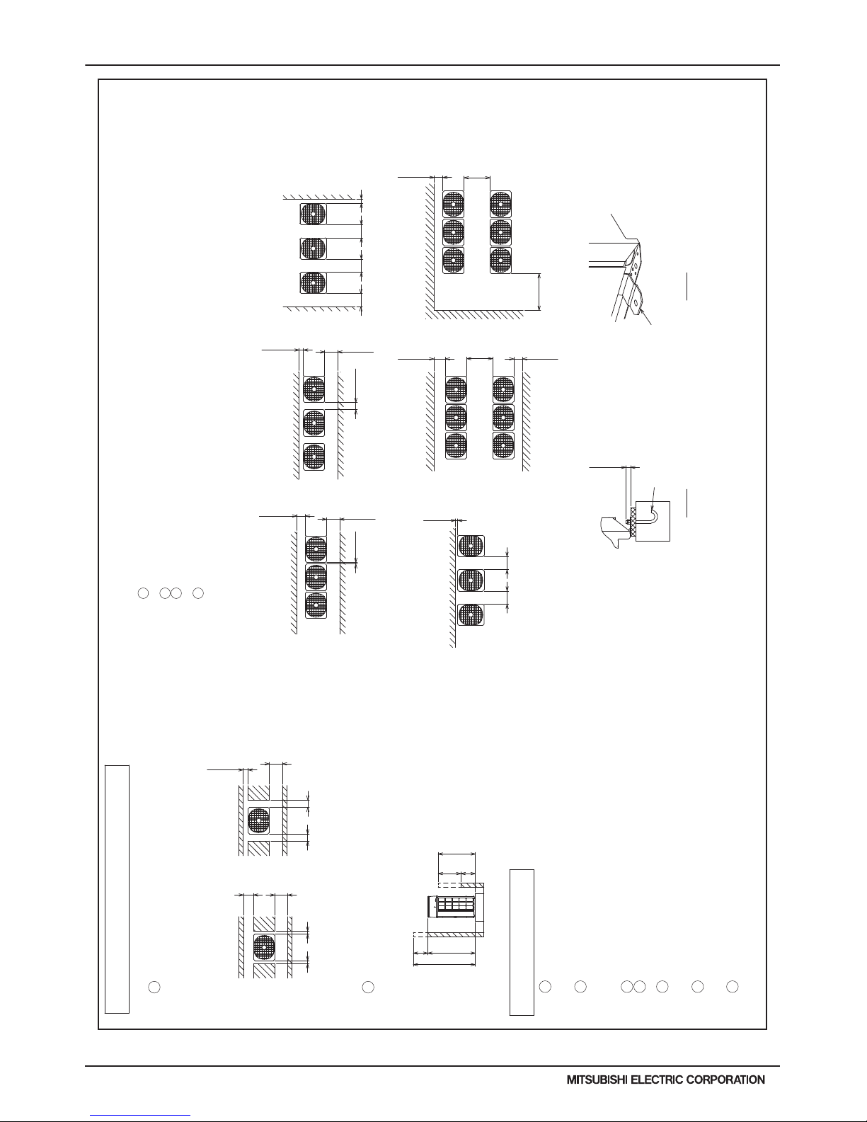
●In case of single installation
1. Required space around the unit
2 When the height of the walls on the front,back or on the sides<H>
exceeds the wall height limit as defined below
add the height that exceeds the height limit <h> to the figures that
are marked with an asterisk.
1 Secure enough space around the unit as shown in the figure below.
2. Foundation work
Wall <H>
Front
Front
Front
Front
Front
Front
Wall <H>
Wall<H>
Front
<Unit:mm(in)>
<To be left open>
Wall <H>
Front
<To be left open>
Wall <H>
Wall <H>
Wall <H>
Wall <H>
<To be left open>
Wall <H>
Wall <H>
Front
Front
<Unit:mm(in)>
1 When multiple units are installed adjacent to each other, secure enough space to allow
for air circulation and walkway between groups of units as shown in the figures below.
2 At least two sides must be left open.
3 As with the single installation, add the height that exceeds the height limit<h>
to the figures that are marked with an asterisk.
4 If there is a wall at both the front and the rear of the unit, install up to six units
consecutively in the side direction and provide a space of 1000mm or more as inlet space/
passage space for each six units.
●In case of collective installation
1 Take into consideration the surface strength, water drainage route,
piping route, and wiring route when preparing the installation site.
<Note that the drain water comes out of the unit during operation.>
2 Build the foundation in such way that the corner of the installation leg is
securely supported as shown in the right figure.(Fig.A)
When using a rubber isolating cushion, please ensure it is large enough
to cover the entire width of each of the unit's legs.
3 The protrusion length of the anchor bolt must not exceed 30mm(1-3/16).(Fig.A)
4 Use four fixing plates as shown in the right figure <field supply required>
when using post-installed anchor bolts.(Fig.B)
5 To prevent small animals and water and snow from entering the unit and damaging its parts,
close the gap around the edges of through holes for pipes and wires with
filler plates <field supply required>.
6 When the pipes or cables are routed at the bottom of the unit,
make sure that the through hole at the base of the unit does not get blocked
with the installation base.
7 Refer to the Installation Manual when installing units on an installation base.
(19-11/16)
(1-3/16)
(35-7/16)
(11-13/16)
(35-7/16) (11-13/16)(11-13/16)
(19/32)
(17-23/32) (17-23/32)
(39-3/8)
(17-23/32)
(17-23/32)
(17-23/32)
(3-15/16)
(3-15/16)
(1-3/16)
(11-13/16)
(3-15/16)
(17-23/32)
(17-23/32)
(1-31/32)(1-31/32)
(3-15/16)
(17-23/32)
(19/32)(19/32)
(11-13/16)
(17-23/32)
<To be left open>
<To be left open>
<To be left open>
<To be left open>
<To be left open>
<To be left open>
<To be left open>
Front
M10 anchor bolt
<field supply required>
Fixing plate
<field supply required>
Front
<Top view><Top view>
Front
<Side view>
• With a space of at least
300mm(11-13/16) to the wall on
the back of the unit
<Wall height limit> Front : Up to the unit height
Back : Up to 500mm(19-11/16) from
the unit bottom
Side : Up to the unit height
Fig.A Fig.B
Unit height
500
900 min.
300 min.*
1000 min.*
300 min.* 300 min.*900 min.
15 min.*
450 min.450 min.
100 min.*
450 min.
450 min.
450 min.*
100 min.
450 min.*
100 min.*
30 min.
300 min.*
450 min.*
100 min.*
450 min.*
450 min.*
300 min.*
15 min.* 15 min.* 50 min.*50 min.*
H
h
h
H
30mm max.
• With a space of at least
100mm(3-15/16) to the wall on
the back of the unit
Page 13
PURY-HP-T(S)KMU,-Y(S)KMU (September 2014)
H2i-R2-13
© 2014 Mitsubishi Electric US, Inc.
2. EXTERNAL DIMENSIONS
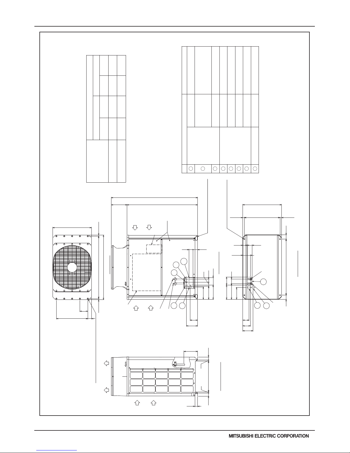
DATA U10
PURY-HP144, 192TSKMU-A-H(-BS)
Unit : mm(in)
30 (1-3/16)
1220 (48-1/16) 1220 (48-1/16)
1650 (64-31/32)
740 (29-5/32)
Front view
Left view
Outdoor unit 2Outdoor unit 1
To BC controller
To BC controller
a
b
e
f
c
d
Twinning pipe(High pressure)
<optional parts>
Twinning pipe(Low pressure)
<optional parts>
Intake
air
Intake
air
Discharge air
Intake
air
Low pressure
Unit model
Component
unit model
ø15.88(5/8) ø19.05(3/4)ccee
ddff
High pressure
HP72 HP96
Twinning Kit
~Outdoor unit
HP72 HP96
(Note 5) (Note 5)
--
ø19.05(3/4)
ø19.05(3/4)
HP144 HP192
Low pressure
Twinning pipe connection size
Outdoor unit 1
Component unit name
Package unit name
BC controller~Twinning pipe
a
b
High pressure
Outdoor Twinning Kit(optional parts)
CMY-R100CBK2
Outdoor unit 2
PURY-HP144TSKMU-A-H(-BS) PURY-HP192TSKMU-A-H(-BS)
PURY-HP72TKMU-A-H(-BS) PURY-HP96TKMU-A-H(-BS)
PURY-HP72TKMU-A-H(-BS) PURY-HP96TKMU-A-H(-BS)
ø28.58(1-1/8)
ø22.2(7/8)
ø15.88(5/8)
ø22.2(7/8)
Note 1. Connect the pipes as shown in the figure above. Refer to the table aboveforthe pipe size.
2. Twinning pipe (High pressure) should not be tilted more than 15 degrees from the horizontal plane.
Be sure to see the Installation Manual for details of Twinning pipe installation.
3. The pipe section before the Twinning pipe (section "a" in the figure) must have at least 500mm(19-11/16) of straight section
(*including the straight pipe that is supplied with the Twinning pipe).
4. Only use the Twinning pipe by Mitsubishi (optional parts).
5. Connect the outdoor unit 1 with the Twinning pipe (Low pressure) (section "d" in the figure).
Page 14
H2i-R2-14
PURY-HP-T(S)KMU,-Y(S)KMU (September 2014)
© 2014 Mitsubishi Electric US, Inc.
2. EXTERNAL DIMENSIONS
DATA U10
H2i R2
PURY-HP72, 96YKMU-A(-BS)
Unit : mm(in)
(1) (1)
(3/4)
(5/8)
(1-25/32)
(2-9/16)
(1-3/4)
(2-15/32)
(7/8)
(1-3/8)
(1-11/32)
(2-1/16)
(3-23/32)(5-29/32)
(3-1/16)(5-17/32)
(3/4) (1) (1)
(7/8)
Connecting pipe specifications
Note1. Please refer to the next page for information
regarding necessary spacing around the
unit and foundation work.
2. At brazing of pipes, wrap the refrigerant service valve
with wet cloth and keep the temperature of
refrigerant service valve under 120°C(248°F).
Refrigerant service
valve <High pressure>
Refrigerant service
valve <Low pressure>
Refrigerant service valve
<Low pressure>
Refrigerant service valve
<High pressure>
(5-3/4)
(1-3/16)
(1-3/16)
(29-5/32)
(Mounting pitch)
(26-23/32~26-15/16)
(26-13/16)
(Mounting pitch)
(3-5/32) (3-5/32)
(10-11/32)
(3-5/16)
(3-23/32)
(10-23/32) 272
(11-7/8) 301
(8-15/16) 227
(2-1/4)(2-1/4)
(13/16)
(13/16)
(3-17/32)
(3-1/16)
1
(9-29/32) 251
(9-5/16) 236
(10-23/32) 272
(11-15/16)
(25/32)(25/32)
(2-25/32)
=(5-29/32)X4
(23-5/8)
<Snow hood attachment hole>
4X5-ø4.6 (3/16) Hole
(Make hole at the plastic fan guard
for snow hood attachment)
Intake
air
Discharge air
Control box
Intake
air
Service
panel
Intake
air
<Sling hole>
3
6
2
4
5
8
2X2-14(9/16)X20(13/16) Oval hole
2X2-80(3-5/32)X35(1-13/32) Oval hole
7
*1 Use the pipe joint(field supply) and connect to the refrigerant service
valve piping.
High
pressure
ø25.4
Low
pressure
Service valveRefrigerant pipe
Diameter
*1
High
pressure
Low
pressure
Model
PURY-HP72YKMU-A(-BS)
ø25.4
ø19.05 Brazed
ø15.88 Brazed
*1
ø45 Knockout hole
Specifications
ø43.7 or ø22.2 Knockout hole
ø62.7 or ø34.5 Knockout hole
Front through hole
Bottom through hole
Bottom through hole
Front through hole
Front through hole
For wires
Usage
Front through hole
Front through hole
(Uses when twinning
kit (optional
parts) is mounted.)
140 × 77 Knockout hole
150 × 94 Knockout hole
Bottom through hole
For pipes
ø52 Knockout hole
For transmission cables
ø34 Knockout hole
ø65 Knockout hole
PURY-HP96YKMU-A(-BS)
ø19.05 Brazed
*1
ø25.4
*1
ø25.4
ø22.2 Brazed
Transformer box
58 (2-5/16)
75 (2-31/32)
(8-9/16) 217
(5-23/32) 145
146 (5-3/4)
146
83 (3-9/32)
262
(740)
150 (5-29/32)
57
54 (2-5/32)
19.5
80 1060 (41-3/4)
586 (23-3/32)
19.5
57
94 84
121 (4-25/32)
600=150×4
20
1220 (48-1/16)
150 (5-29/32)
1650 (64-31/32)
196 (7-23/32)
1347 (53-1/16)
89
303
20
740 (29-5/32)
70
1181 (46-1/2)
140 (5-17/32)
80
77
681(678~684)29.5 29.5
Bottom view
Left side view
Front view
Top view
NO.
1
2
3
465
8
7
Page 15
PURY-HP-T(S)KMU,-Y(S)KMU (September 2014)
H2i-R2-15
© 2014 Mitsubishi Electric US, Inc.
2. EXTERNAL DIMENSIONS
DATA U10
PURY-HP72, 96YKMU-A(-BS)
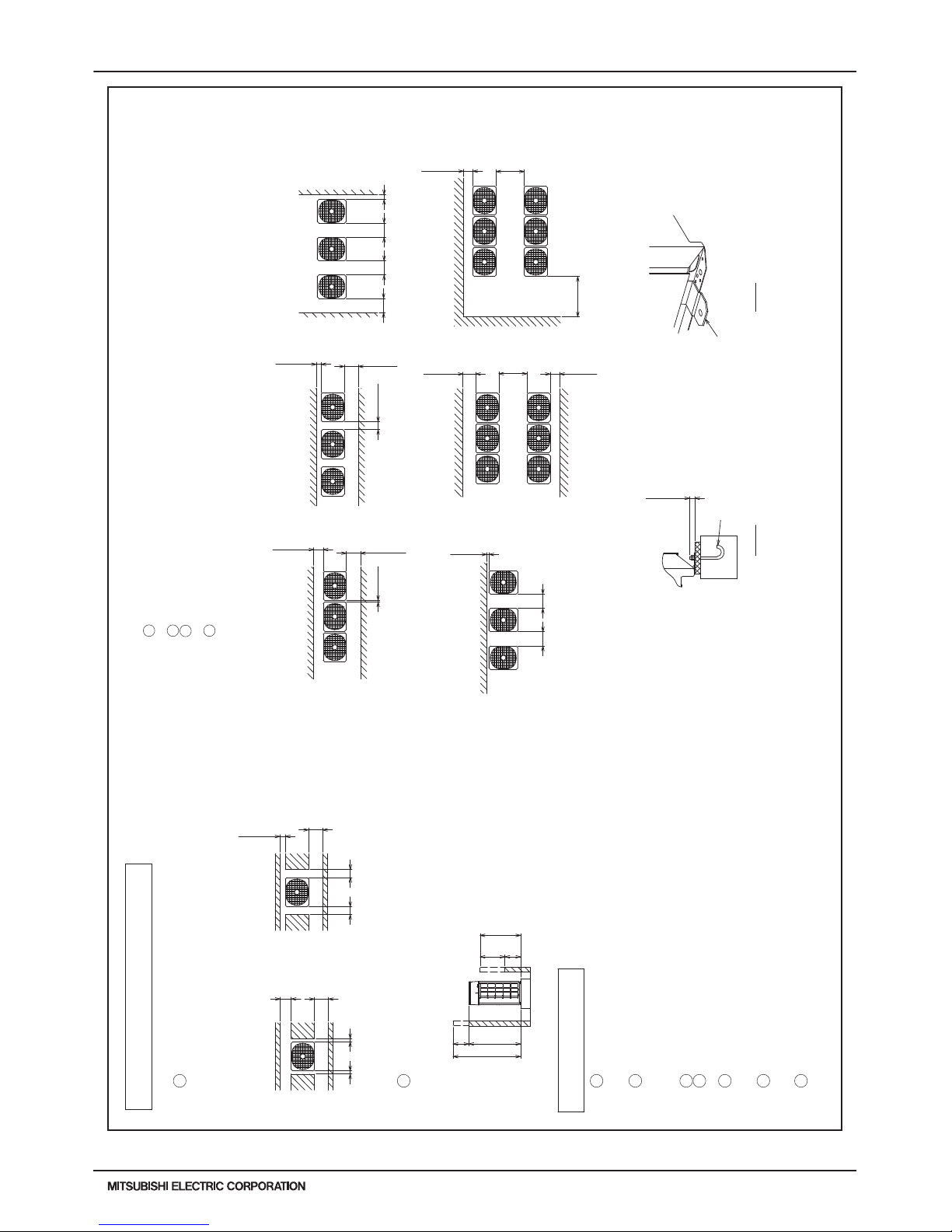
Unit : mm(in)
Front
Front
Front
Front
Front
Front
Wall <H>
Front
<Unit:mm(in)>
<To be left open>
Front
<To be left open>
<To be left open>
Wall <H>
Front
Front
<Unit:mm(in)>
1 When multiple units are installed adjacent to each other, secure enough space to allow
for air circulation and walkway between groups of units as shown in the figures below.
2 At least two sides must be left open.
3 As with the single installation, add the height that exceeds the height limit<h>
to the figures that are marked with an asterisk.
4 If there is a wall at both the front and the rear of the unit, install up to six units
consecutively in the side direction and provide a space of 1000mm or more as inlet space/
passage space for each six units.
●In case of collective installation
1 Take into consideration the surface strength,water drainage route,
piping route,and wiring route when preparing the installation site.
<Note that the drain water comes out of the unit during operation.>
2 Build the foundation in such way that the corner of the installation leg is
securely supported as shown in the right figure.(Fig.A)
When using a rubber isolating cushion, please ensure it is large enough
to cover the entire width of each of the unit's legs.
3 The protrusion length of the anchor bolt must not exceed 30mm(1-3/16).(Fig.A)
4 Use four fixing plates as shown in the right figure <field supply required>
when using post-installed anchor bolts.(Fig.B)
5 To prevent small animals and water and snow from entering the unit and damaging its parts,
close the gap around the edges of through holes for pipes and wires with
filler plates <field supply required>.
6 When the pipes or cables are routed at the bottom of the unit,
make sure that the through hole at the base of the unit does not get blocked
with the installation base.
7 Refer to the Installation Manual when installing units on an installation base.
Wall <H>
Wall <H>
Wall <H>
Wall <H>
Wall <H>
Wall <H>
Wall <H>
Wall <H>
●In case of single installation
1. Required space around the unit
2 When the height of the walls on the front,back or on the sides<H>
exceeds the wall height limit as defined below
add the height that exceeds the height limit <h> to the figures that
are marked with an asterisk.
1 Secure enough space around the unit as shown in the figure below.
2. Foundation work
(19-11/16)
(1-3/16)
(35-7/16)
(11-13/16)
(35-7/16)
(11-13/16)
(11-13/16)
(19/32)
(17-23/32)
(17-23/32)
(39-3/8)
(17-23/32)
(17-23/32)
(17-23/32)
(3-15/16)
(3-15/16)
(1-3/16)
(11-13/16)
(3-15/16)
(17-23/32)
(17-23/32)
(1-31/32)
(1-31/32)
(3-15/16)
(17-23/32)
(19/32)
(19/32)
(11-13/16)
(17-23/32)
<To be left open>
<To be left open>
<To be left open>
<To be left open>
<To be left open>
<To be left open>
<To be left open>
Front
M10 anchor bolt
<field supply required>
Fixing plate
<field supply required>
Front
<Top view>
<Top view>
Front
<Side view>
• With a space of at least
100mm(3-15/16) to the wall on
the back of the unit
• With a space of at least
300mm(11-13/16) to the wall on
the back of the unit
Fig.A Fig.B
Unit height
500
900 min.
300 min.*
1000 min.*
300 min.* 300 min.*
900 min.
15 min.*
450 min. 450 min.
100 min.*
450 min.
450 min.
450 min.*
100 min.
450 min.*
100 min.*
30 min.
300 min.*
450 min.*
100 min.*
450 min.*
450 min.*
300 min.*
15 min.*
15 min.*
50 min.*
50 min.*
H
h
h
H
30mm max.
<Wall height limit> Front : Up to the unit height
Back : Up to 500mm(19-11/16) from
the unit bottom
Side : Up to the unit height
Page 16
H2i-R2-16
PURY-HP-T(S)KMU,-Y(S)KMU (September 2014)
© 2014 Mitsubishi Electric US, Inc.
2. EXTERNAL DIMENSIONS
DATA U10
H2i R2
PURY-HP144, 192YSKMU-A(-BS)
Unit : mm(in)
Low pressure
Unit model
Component
unit model
ø15.88(5/8) ø19.05(3/4)
ccee
ddff
High pressure
HP72 HP96
Twinning Kit
~Outdoor unit
HP72 HP96
(Note 5) (Note 5)
--
ø19.05(3/4)
ø19.05(3/4)
HP144 HP192
Low pressure
Twinning pipe connection size
Outdoor unit 1
Component unit name
Package unit name
BC controller~Twinning pipe
a
b
High pressure
Outdoor Twinning Kit(optional parts)
CMY-R100CBK2
Outdoor unit 2
PURY-HP144YSKMU-A(-BS) PURY-HP192YSKMU-A(-BS)
PURY-HP72YKMU-A(-BS) PURY-HP96YKMU-A(-BS)
PURY-HP72YKMU-A(-BS) PURY-HP96YKMU-A(-BS)
ø28.58(1-1/8)
ø22.2(7/8)
ø15.88(5/8)
ø22.2(7/8)
Note 1. Connect the pipes as shown in the figure above. Refer to the table above for the pipe size.
2. Twinning pipe (High pressure) should not be tilted more than 15 degrees from the horizontal plane.
Be sure to see the Installation Manual for details of Twinning pipe installation.
3. The pipe section before the Twinning pipe (section "a" in the figure) must have at least 500mm(19-11/16) of straight section
(*including the straight pipe that is supplied with the Twinning pipe).
4. Only use the Twinning pipe by Mitsubishi (optional parts).
5. Connect the outdoor unit 1 with the Twinning pipe (Low pressure) (section "d" in the figure).
30 (1-3/16)
1220 (48-1/16) 1220 (48-1/16)
1650 (64-31/32)
740 (29-5/32)
Front view
Left view
Outdoor unit 2Outdoor unit 1
To BC controller
To BC controller
a
b
e
f
c
d
Twinning pipe(High pressure)
<optional parts>
Twinning pipe(Low pressure)
<optional parts>
Intake
air
Intake
air
Discharge air
Intake
air
Page 17
PURY-HP-T(S)KMU,-Y(S)KMU (September 2014)
H2i-R2-17
© 2014 Mitsubishi Electric US, Inc.
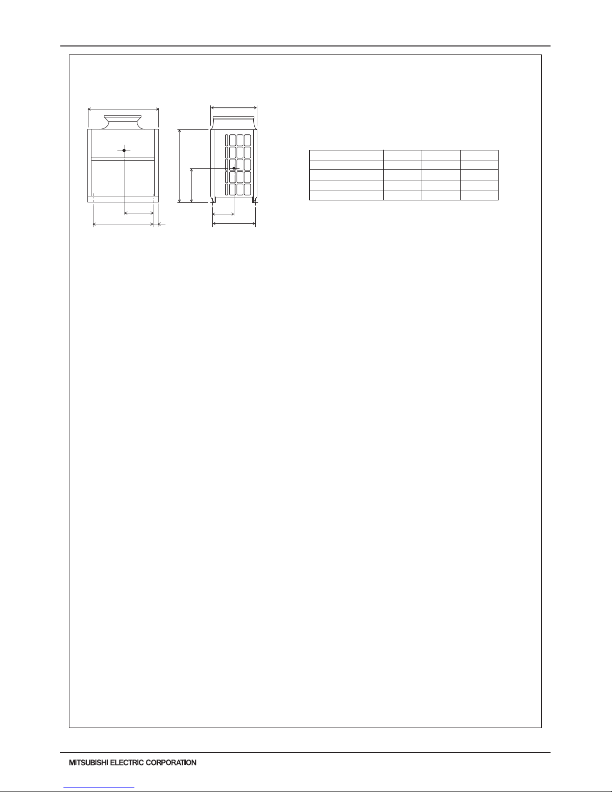
3. CENTER OF GRAVITY
DATA U10
1060
80
1220
X
Y
681
740
1347
Z
PURY-HP72, 96TKMU-A-H (-BS)
PURY-HP72, 96YKMU-A (-BS)
Model X Y Z
Unit : mm[in.]
PURY-HP72YKMU-A
PURY-HP96YKMU-A
460[18-1/8]
447[17-5/8]
447[17-5/8]
435[17-5/32]
320[12-5/8]
311[12-1/4]
310[12-7/32]
302[11-29/32]
609[23]
595[23-7/16]
623[24-17/32]
610[24-1/32]
PURY-HP72TKMU-A-H
PURY-HP96TKMU-A-H
Page 18
H2i-R2-18
PURY-HP-T(S)KMU,-Y(S)KMU (September 2014)
© 2014 Mitsubishi Electric US, Inc.
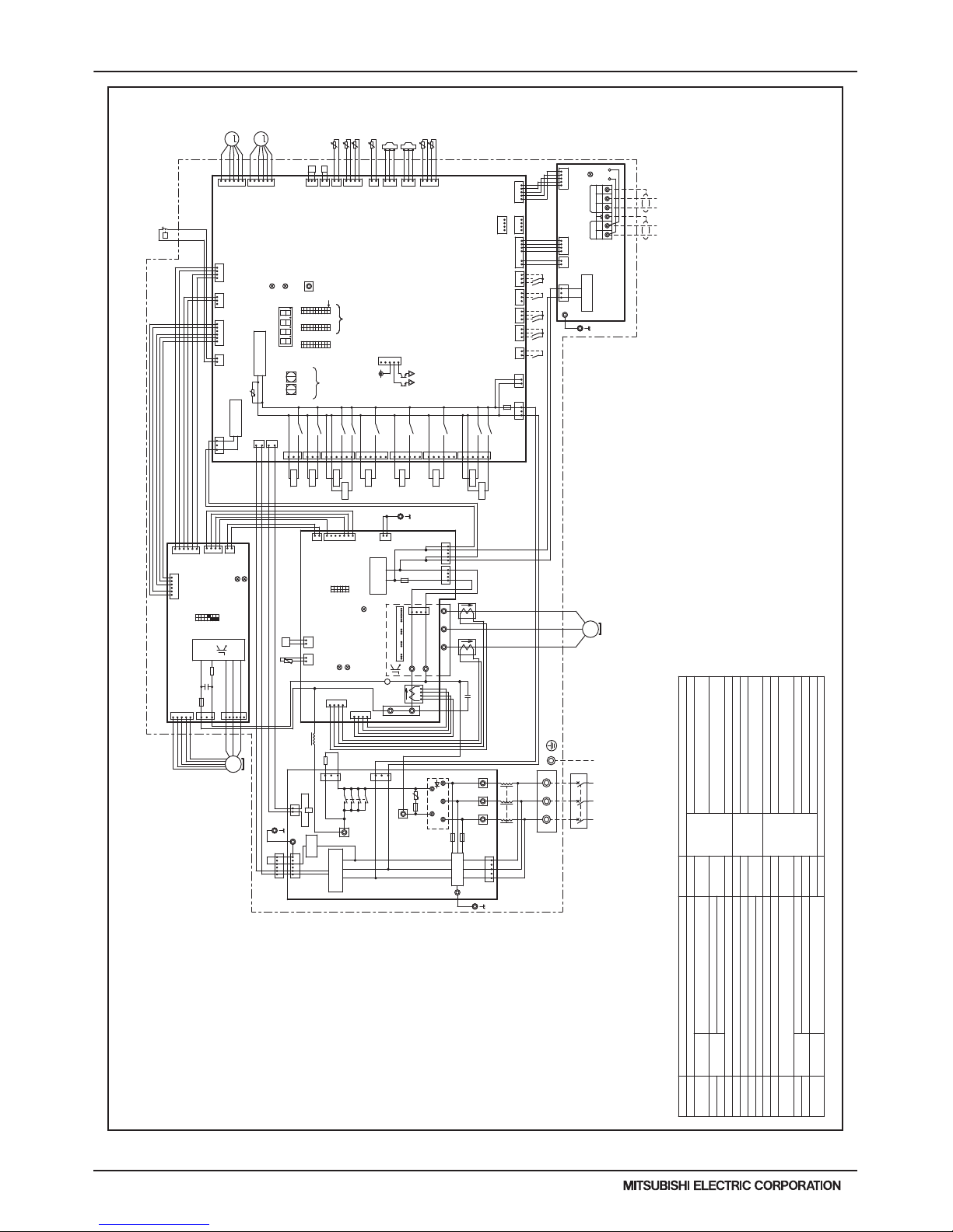
4. ELECTRICAL WIRING DIAGRAMS
DATA U10
H2i R2
PURY-HP72, 96TKMU-A-H(-BS)
For opening/closing the bypass
circuit
Terminal
block
Central control transmission
cable
Power supply
Function setting connector
IPM temperature
Heat exchanger outlet pipe temperature
ACC inlet pipe temperature
Discharge pipe temperature
Thermistor
SV9
TB1
TB3
TB7
TH4
TH5
TH6
THHS
Z24,25,26
DC reactor
Current sensor(AC)
Low pressure
Discharge pressure
High pressure protection for the
outdoor unit
Pressure
switch
Pressure
sensor
Explanation
Explanation
4-way valve (Cooling/Heating switching)
For opening/closing the bypass circuit
under the O/S
Solenoid
valve
Solenoid
valve
DCL
LEV5a
ACCT1,2
63LS
63HS1
63H1
<Symbol explanation>
Symbol
Symbol
21S4a
C1
DCCT1
SV1a
SV5b
Outdoor unit heat exchanger
capacity control
SV4a,b,d
Subcooled liquid refrigerant
temperature
*1. Single-dotted lines indicate wiring not
supplied with the unit.
*2. Dot-dash lines indicate the control box
boundaries.
*3. Refer to the Data book for connecting
input/output signal connectors.
*4. Daisy-chain terminals (TB3) on the outdoor
units in the same refrigerant system together.
*5. Faston terminals have a locking function.
Make sure the terminals are securely locked
in place after insertion. Press the tab on
the terminals to removed them.
*6. Control box houses high-voltage parts.
Before inspecting the inside of the control box,
turn off the power,keep the unit off for at
least 10 minutes, and confirm that the voltage
at both ends of the main capacitor (C1) has
dropped to DC20V or less.
X001
For inrush current preventionR1
Choke coil (for high frequency noise reduction)L
Indoor/Outdoor transmission cable
Magnetic relay (inverter main circuit)72C
Heat exchanger capacity control
Linear expansion valve (for the control of
evaporating temperature)
Resistor
For current detection
RSH01
Capacitor (inverter main circuit)
Current sensor(DC)
For opening/closing the injection circuitLEV4
For opening/closing the defrost circuit
SV10,11
OA temperature
TH7
TH9,11
Ground
L3L2
L1
X14
X13
613
5
12
red
CNPS
132
1
TP1 TP2
TB3
2
3
TB7
M1 M2 M1 M2 S
512 34
1
2
t
°
1
2
132
346
122
CN82
blue
134
CN83
black
31
6
X12
1
3
CN508
blue
CN4
black
231
t
SW001
1
3
°
CN2
7
12
1
3
31
432
2
3
1
1
TH4
t
4
°
1
1
CN211
green
23
123
321
6
CNSNR
54321
U
V
W
Fan motor
(Heat exchanger)
MS
3~
416
CNINV
2
SW1
1
6
OFF ON
3
2
23
Power failure
detection circuit
red
1
Surge
absorber
2
3
1
TB1
L3L2L1
21
INV Board
°
t
2
L
yellow
CNPOW
t
°
654
5
CNVDC
4
CNDC2
1
ACCT2
F02
AC250V
3.15A T
C1
IPM
4
X10
ON
X08
Unit address
setting
LED3:Charge
6
316
F001
AC250V
6.3A T
F002
AC250V
6.3A T
RSH01
CN001
531
TB22 TB23TB21
Diode stack
~~~
12
34
3
green
CN62
CN990
green
CNTYP4
CN201
Z25
1
TH5
2
SWU2
LED1
SW6
10
Control Board
CN40
63HS1
CN41
TH7
15
543
1
SW4
LED3
2
LEV5a
3
SET UP(SW6-10)
V
M
OFF
CN506
red
yellow
CN3K
*3
Compressor ON/OFF output
Error detection output
DC12V
CN51
SV5b
W
blue
CN3N
1
334
TB7 Power
selecting
connector
CNVDC
IPM
5
1
26
ON
OFF
M-NET power
supply circuit
12
M-NET Board
Power failure
detection circuit
Indoor/Outdoor
transmission
cable
ON
1's
digit
CN102
1
4
1
U
10's
digit
OFF
LED2:Normal operation(Lit)
/ Error(Blink)
yellow
CNDC
red
MS
3~
2
TH6
U
LED1:Power supply to
Indoor/Outdoor
transmission line
ZNR400
Central control
transmission
cable
ONOFF
Motor
(Compressor)
red
CN3S
1
CN04
red
CN43
yellow
CN61
green
CN202
red
8
/ Error(Blink)
*4
2
P
63H1
4
1
SW5
10
5
CN3D
1
CPU power
supply circuit
black
CNAC2
1
*3
ONOFF
10
SWU1
N
CN212
red
WU
P
6
CNDC1
1
4
V
1
CN80
25
F301
AC250V
15A T
CNIPM
CNTYP5
green
LED4:CPU in operation
FT-N
LED1:Normal operation(Lit)
/ Error(Blink)
CN801
red
SWP1
CN012
1
3
FAN Board
63LS
U
-
+
ZNR005
Z24
2
CN507
black
3
F003
AC250V
6.3A T
TB42
6
4
X001
CN213
green
black
*5
SV9
Function
setting
LED1
Display
setting/
Function
setting
red
LED4:CPU in operation
5
1
SC-P1
DCL
black
CN72C
red
3
1
DCCT1
1
2
1
4
1
CNLVA
1
CNR1
red
black
F01
AC250V
3.15A T
TB31
R1
white
red
CNIT
red
X001
12
Power Source
3~
60Hz
208/230V
CNCT
red
white
ACCT1
56
CN110
Noise filter
31
6412
IPM power
supply circuit
CNFG2
Noise
Filter
black
432
1
CNCT2
blue
432
1
X05
X06
351
6
CN505
13
12
CNFG
blue
1
2
black
redwhite
*5
black
red
THHS
°
t
Z26
CNTYP
2
CNTH
green
21
CN110
black
2
1
red
1
2
1
CNAC
CN81
green
12
5
134
4
SV4a
4
CN2
C310,C311
SV4d
SV1a
SV4b
21S4a
12346
M
CNLVE
yellow
LEV4
TH9
TH11
t
°
2
CN509
yellow
CNS2
32
3
1
X04
yellow
CN504
SV11
3
1
X03
green
CN503
SV10
CN72C
green
LED1:Normal operation(Lit)
Page 19
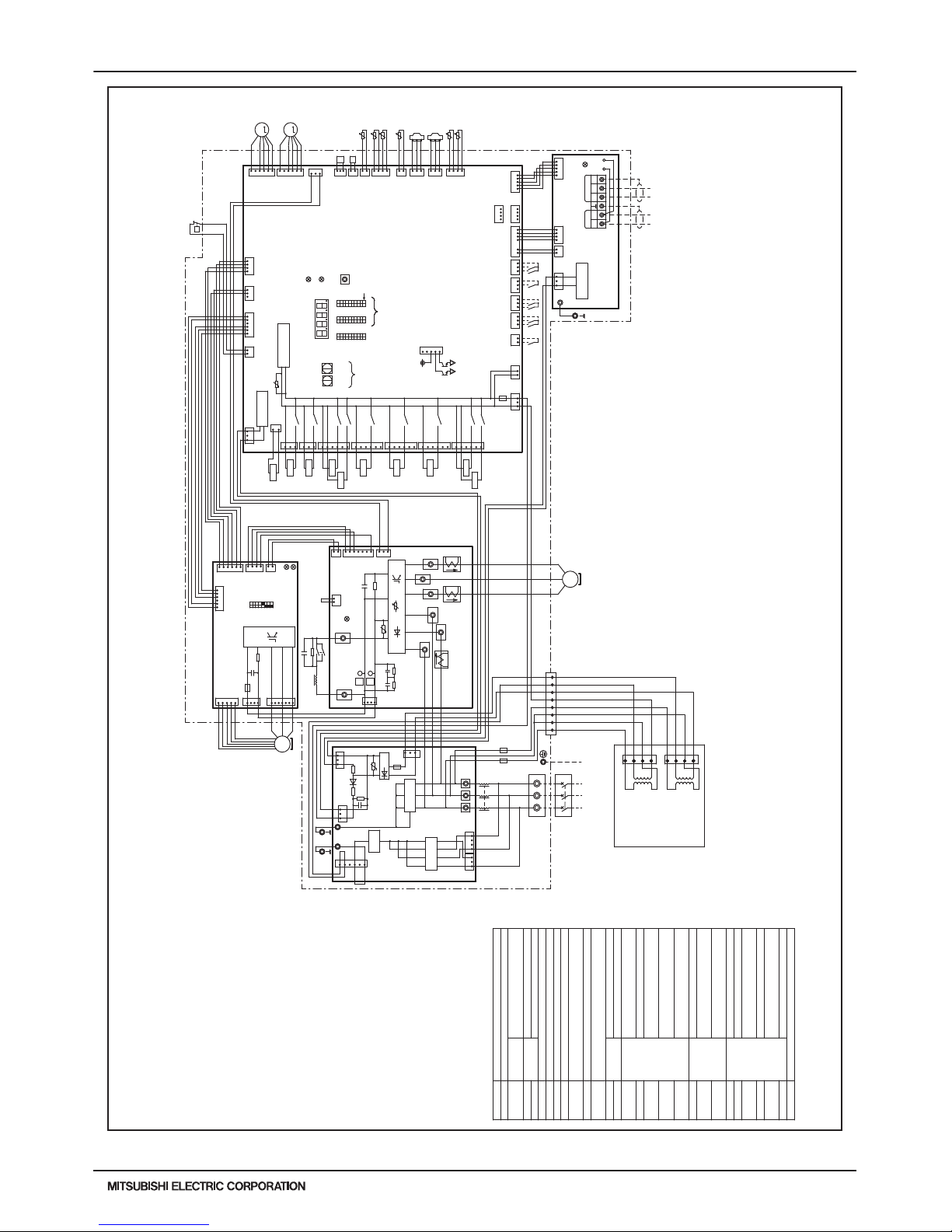
PURY-HP-T(S)KMU,-Y(S)KMU (September 2014)
H2i-R2-19
© 2014 Mitsubishi Electric US, Inc.
4. ELECTRICAL WIRING DIAGRAMS
DATA U10
PURY-HP72, 96YKMU-A(-BS)
For opening/closing the bypass
circuit
Terminal
block
Central control transmission
cable
Indoor/Outdoor transmission
cable
Power supply
Function setting connector
IPM temperature
OA temperature
ACC inlet pipe temperature
Discharge pipe temperatureThermistor
SV9
TB1
TB3
TB7
TH4
TH5
TH6
TH7
THHS
Z24,25
DC reactor
Current sensor(AC)
Magnetic relay(inverter main circuit)
Low pressure
Discharge pressure
High pressure protection for
the outdoor unit
Pressure
switch
Pressure
sensor
Explanation
4-way valve(Cooling/Heating switching)
For opening/closing the bypass
circuit under the O/S
Solenoid
valve
DCL
LEV5a
CT12,22,3
72C
63LS
63HS1
63H1
<Symbol explanation>
Symbol
21S4a
SV1a
SV5b Outdoor unit heat exchanger
capacity control
Subcooled liquid refrigerant
temperature
*1. Single-dotted lines indicate wiring not supplied
with the unit.
*2. Dot-dash lines indicate the control box boundaries.
*3. Refer to the Data book for connecting input/output
signal connectors.
*4. Daisy-chain terminals (TB3) on the outdoor units in the
same refrigerant system together.
*5. Faston terminals have a locking function.
Make sure the terminals are securely locked in place
after insertion. Press the tab on the terminals to
removed them.
*6. Control box houses high-voltage parts.
Before inspecting the inside of the control box,turn off
the power,keep the unit off for at least 10 minutes, and
confirm that the voltage between FT-P and FT-N on
INV Board has dropped to DC20V or less.
For inrush current preventionResistorR1,5
Heat exchanger capacity controlSV4a,b,d
L
Capacitor (inverter main circuit)C30~C37
For current detection
RSH01,RSH1
Linear expansion valve (for the control of
evaporating temperature)
Choke coil
(for high frequency noise reduction)
LEV4 For opening/closing the injection circuit
For opening/closing the defrost
circuit
SV10,11
Heat exchanger outlet pipe
temperature
TH9,11
12
L3
red
CNPS
132
1
TP1TP2
TB3
2
3
TB7
M1 M2 M1 M2 S
1
512 34
1
2
t
°
1
2
132
346
3
615
31
2
2
CN82
blue
134
CN83
black
L1
L2
31
Fan motor
(Heat exchanger)
U
V
W
CNINV
714
34
CN4
black
1
13
231
t
3
SW001
1
4
°
CN2
1
12
1
3
31
432
2
3
1
1
CNSNR
TH4
t
4
°
1
1
1
CN211
green
23
123
321
U
5
Transformer Box
CNTR3
3
4
CNTR2
T02
(Transformer)
223
4
T03
(Transformer)
1
1
2
54321
1
3
2
1
23
123
1
CN6
21
°
t
2
yellow
CNPOW
t
°
1
654
X10
ON
X08
Unit address
setting
CT12
CN5
red
D1
R4
-
Z5
1
+
316
CNTR1
12
L1 L2 L2
3
L3
45678
RSH01
white
Ground
12
34
3
white
red
black
black
white
red
F4
AC600V
6A F
F5
AC600V
6A F
green
CN62
CN990
green
CNTYP4
F4
AC250V
6.3A T
R5
CN201
Z25
1
TH5
2
SWU2
LED1
SW6
10
Control Board
CN40
63HS1
CN41
TH7
15
234
1
SW4
LED3
5
LEV5a
3
3
SET UP(SW6-10)
SC-V
CT22
SC-U
V
CN4
blue
red
M
OFF
t
black
CN506
red
CNTYP2
black
6
yellow
CN3K
*3
Compressor ON/OFF output
Error detection output
TB21
DC12V
CN51
SV5b
CN1A
U
CN2
blue
CN3N
1
3
+
3
4
TB1
CN1B
TB7 Power
selecting
connector
CNVDC
1
IPM
2
5
6
L3
DCL
black
72C
white
red
26
ON
OFF
M-NET power
supply circuit
12
M-NET Board
Power failure
detection circuit
Indoor/Outdoor
transmission
cable
INV Board
red
TB23
L2L1
+
ON
1's
digit
THHS
CN102
C31,C33,
C35,C37
1
4
1
W
10's
digit
OFF
LED2:Normal operation(Lit)
/ Error(Blink)
yellow
CNDC
red
red
MS
3
~
2
C100
*5
TH6
U
LED1:Power supply to
Indoor/Outdoor
transmission line
ZNR400
+
black
Central control
transmission
cable
*6
SC-L1
ONOFF
FT-N
R30,R32,
R34
Motor
(Compressor)
red
CN3S
1
CN04
red
CN43
1
SC-P2
P
CN61
green
CN202
red
C30,C32,
C34,C36
8
N
CN1
LED1: Normal operation(Lit)
/ Error(Blink)
*4
SC-W
SC-L3
2
P
63H1
4
1
SW5
10
5
CN3D
1
CPU power
supply circuit
black
CNAC2
1
*3
ONOFF
10
SWU1
white
CN212
red
SC-L2
6
2
CN80
F301
DC700V
4A T
CNTYP5
green
LED4:CPU in operation
LED1:Normal operation(Lit)
/ Error(Blink)
CN801
red
5
°
IPM
4
SC-P1
FT-P
black
red
DB1
CT3
C1
CNTYP
black
black
TB22
SWP1
RSH1
R6
C11
FAN Board
63LS
ZNR1
U
L
Noise
Filter
Z24
2
CN507
black
336
4
CN213
green
CN6
yellow
SV9
Function
setting
LED1
Display
setting/
Function
setting
72C
Noise filter
Noise filter
6
7
red
Surge
absorber
1
2
1
CNLVA
1
F01
AC250V
3.15A T
MS
3~
white black
1
CNIT
red
L1 L2 L3
R31,R33,
R35
3
4
1
R1,R5
X05
X06
351
6
CN505
13
X13
SV4d
X14
X12
163
CN508
blue
163
CNAC
CN81
green
12
5
134
SV4a
SV4b
4
4
CN2
C310,C311
SV1a
21S4a
5
Power Source
3~
60Hz
460V
12346
M
CNLVE
LEV4
yellow
TH9
TH11
t
°
2
CNS2
CN509
yellow
X04
3
1
yellow
SV11
CN504
X03
3
1
green
CN503
SV10
green
CN72
yellow
Page 20
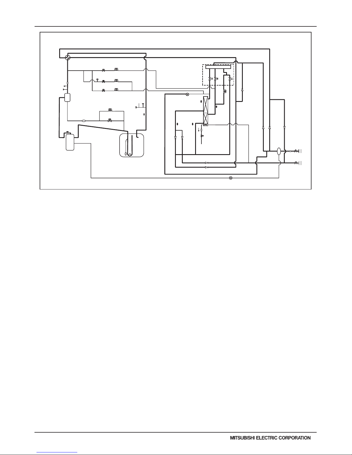
H2i-R2-20
PURY-HP-T(S)KMU,-Y(S)KMU (September 2014)
© 2014 Mitsubishi Electric US, Inc.
5. REFRIGERANT CIRCUIT DIAGRAMS
PURY-HP72, HP96YKMU-A(-BS)
Solenoid valve block
TH4
CJ2
BV2
COMP
21S4a
ST1
63LS
BV1
CV8a
CV6a
TH7
SV4a
SV4b
SV4d
ACC
ST6
ST7
ST17
TH5
TH6
CV9a
TH9 TH11
SV9
SV10
SV11
CV4a
CV2a
CV7a
CV3a
CV5a
CJ1
SV5b
HEX
ST18
63HS1
63H1
ST3
CP1
SV1a
LEV5a
LEV4
*1
*1
CP3
CP2
CP4
CP5
O/S
PURY-HP72, HP96TKMU-A-H
PURY-HP72, HP96YKMU-A
Page 21
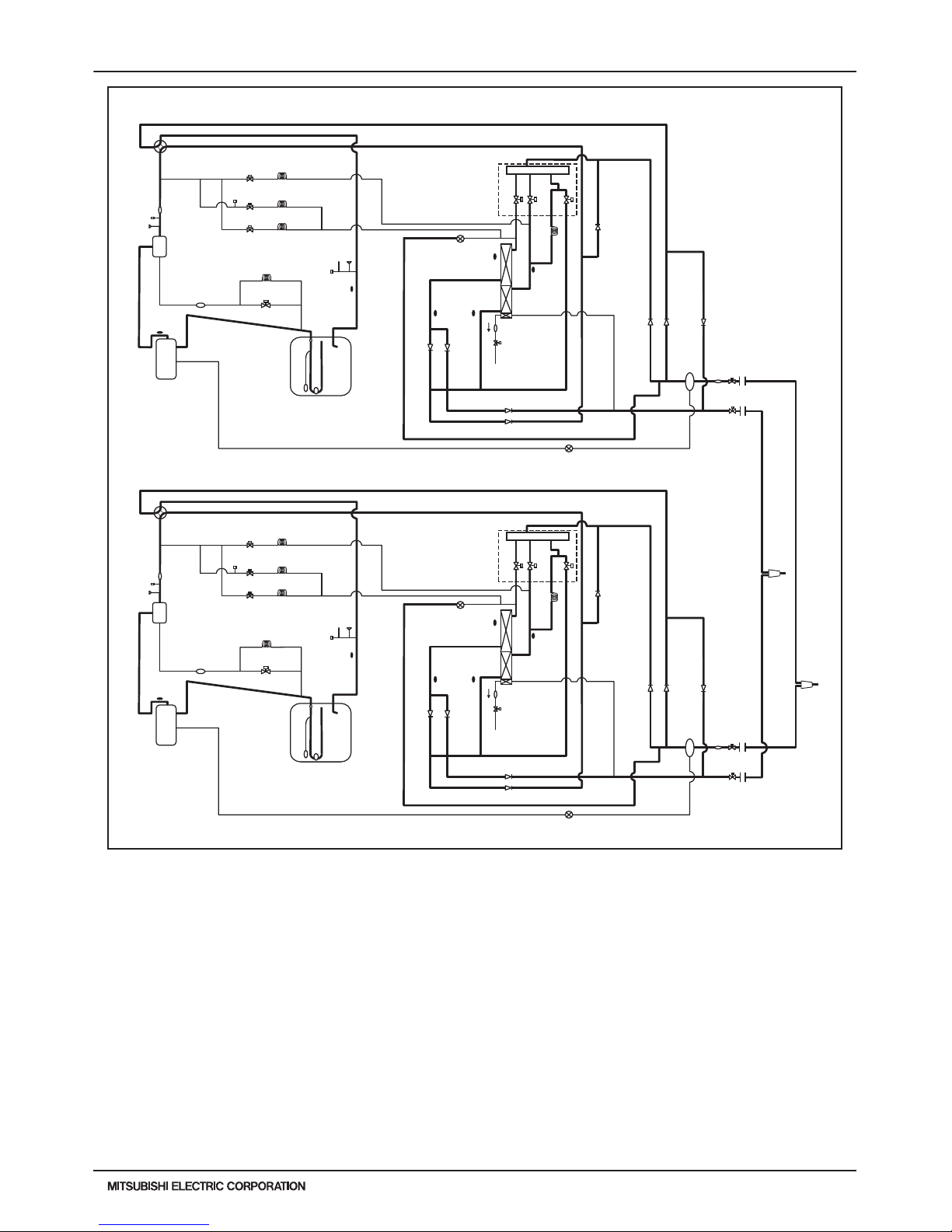
PURY-HP-T(S)KMU,-Y(S)KMU (September 2014)
H2i-R2-21
© 2014 Mitsubishi Electric US, Inc.
5. REFRIGERANT CIRCUIT DIAGRAMS
[3-2 Outdoor Unit Refrigerant Circuit Diagrams ]
(2) PURY-HP144, HP192TSKMU-A-H(-BS)
PURY-HP144, HP192YSKMU-A(-BS)
*1
Low-pressure
side distributor
High-pressure
side junction pipe
Solenoid valve block
Solenoid valve block
O/S
TH4
CJ2
BV2
COMP
21S4a
ST1
63LS
BV1
CV8a
CV6a
TH7
SV4a
SV4b
SV4d
ACC
ST6
ST7
ST17
TH5
TH6
CV9a
TH9 TH11
SV9
SV10
SV11
CV4a
CV2a
CV7a
CV3a
CV5a
CJ1
SV5b
HEX
ST18
63HS1
63H1
ST3
CP1
SV1a
LEV5a
LEV4
*1
CP3
CP2
CP4
CP5
O/S
TH4
CJ2
BV2
COMP
21S4a
ST1
63LS
BV1
CV8a
CV6a
TH7
SV4a
SV4b
SV4d
ACC
ST6
ST7
ST17
TH5
TH6
CV9a
TH9 TH11
SV9
SV10
SV11
CV4a
CV2a
CV7a
CV3a
CV5a
CJ1
SV5b
HEX
ST18
63HS1
63H1
ST3
CP1
SV1a
LEV5a
LEV4
*1
*1
CP3
CP2
CP4
CP5
PURY-HP144, HP192TSKMU-A-H
PURY-HP144, HP192YSKMU-A
Page 22
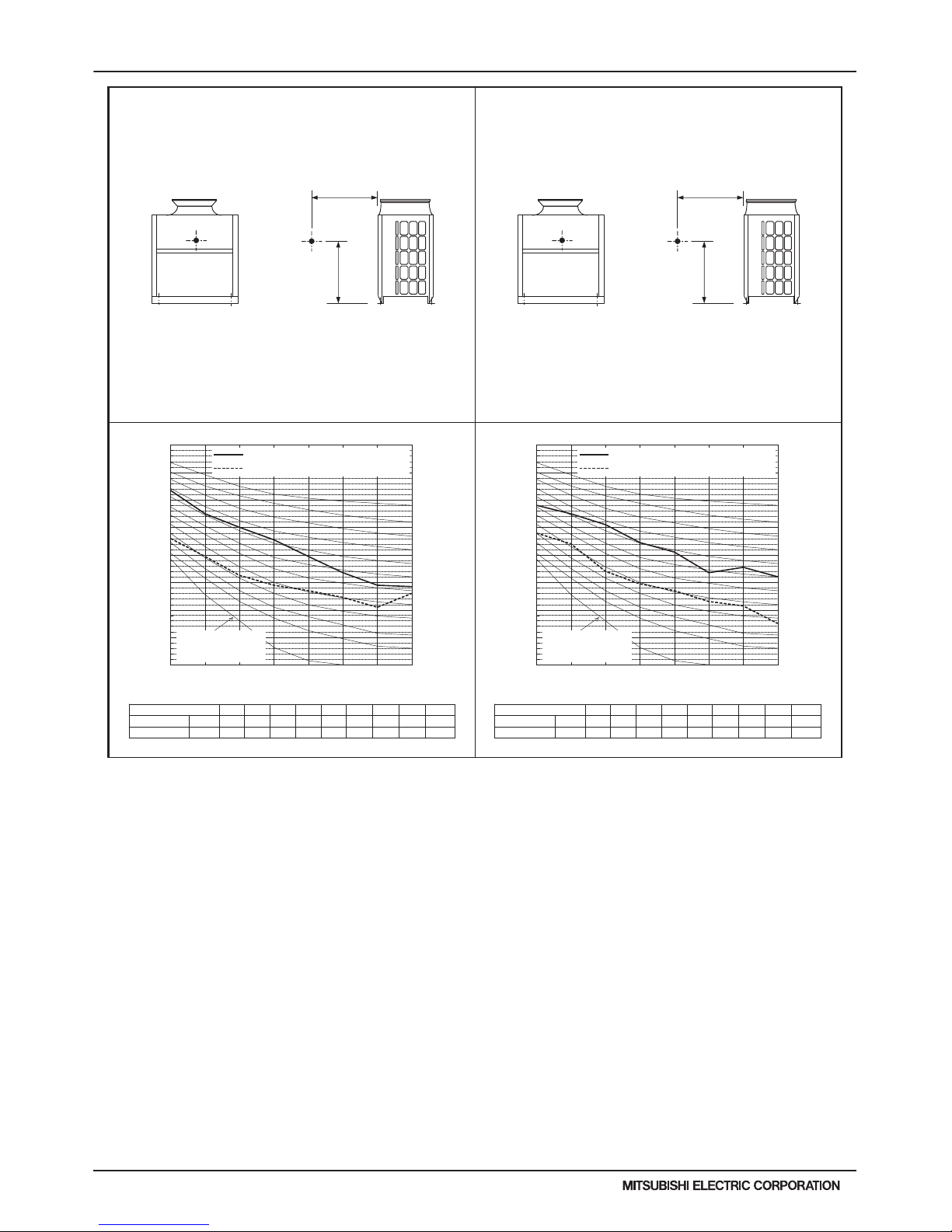
H2i-R2-22
PURY-HP-T(S)KMU,-Y(S)KMU (September 2014)
© 2014 Mitsubishi Electric US, Inc.
6. SOUND PRESSURE LEVELS
5. SOUND LEVELS
DATA U10
H2i R2
5. SOUND LEVELS
Measurement
location
1m
1m
Measurement condition
PURY-HP72TKMU-A-H/YKMU-A
Measurement
location
1m
1m
Measurement condition
PURY-HP96TKMU-A-H/YKMU-A
63 125 250 500 1k 2k 4k 8k dB(A)
Standard 60Hz
73.5 65.0 60.0 55.5 49.5 43.5 39.0 38.5 58.0
Low noise mode 60Hz
56.0 49.5 42.5 39.0 37.0 34.5 31.0 36.0 44.0
When Low noise mode is set,the A/C system's capacity is limited. The system could return to normal operation
from Low noise mode automatically in the case that the operation condition is severe.
10
20
30
40
50
60
70
80
90
63 125 250 500 1k 2k 4k 8k
NC-40
NC-30
NC-20
NC-60
NC-50
NC-70
Octave band central frequency (Hz)
Octave band sound level (dB)
Approximate minimum
audible limit on
continuous noise
Stand 60Hz
Low 60Hz
Sound level of PURY-HP72TKMU-A-H(-BS)/YKMU-A(-BS)
63 125 250 500 1k 2k 4k 8k dB(A)
Standard 60Hz
68.0 65.0 61.0 54.5 51.0 43.5 45.5 42.0 58.0
Low noise mode 60Hz
58.0 54.0 44.0 39.5 37.0 33.0 31.5 25.0 44.0
When Low noise mode is set,the A/C system's capacity is limited. The system could return to normal operation
from Low noise mode automatically in the case that the operation condition is severe.
10
20
30
40
50
60
70
80
90
63 125 250 500 1k 2k 4k 8k
NC-40
NC-30
NC-20
NC-60
NC-50
NC-70
Octave band central frequency (Hz)
Octave band sound level (dB)
Approximate minimum
audible limit on
continuous noise
Stand 60Hz
Low 60Hz
Sound level of PURY-HP96TKMU-A-H(-BS)/YKMU-A(-BS)
Page 23

PURY-HP-T(S)KMU,-Y(S)KMU (September 2014)
H2i-R2-23
© 2014 Mitsubishi Electric US, Inc.
6. SOUND PRESSURE LEVELS
5. SOUND LEVELS
DATA U10
Measurement
location
1m
Measurement condition
PURY-HP144TSKMU-A-H/YSKMU-A
Measurement
location
1m
Measurement condition
PURY-HP192TSKMU-A-H/YSKMU-A
63 125 250 500 1k 2k 4k 8k dB(A)
Standard 60Hz
76.5 68.0 63.0 58.5 52.5 46.5 42.0 41.5 61.0
Low noise mode 60Hz
59.0 52.5 45.5 42.0 40.0 37.5 34.0 39.0 47.0
When Low noise mode is set,the A/C system's capacity is limited. The system could return to normal operation
from Low noise mode automatically in the case that the operation condition is severe.
10
20
30
40
50
60
70
80
90
63 125 250 500 1k 2k 4k 8k
NC-40
NC-30
NC-20
NC-60
NC-50
NC-70
Octave band central frequency (Hz)
Octave band sound level (dB)
Approximate minimum
audible limit on
continuous noise
Stand 60Hz
Low 60Hz
Sound level of PURY-HP144TSKMU-A-H(-BS)/YSKMU-A(-BS)
63 125 250 500 1k 2k 4k 8k dB(A)
Standard 60Hz
71.0 68.0 64.0 57.5 54.0 46.5 48.5 45.0 61.0
Low noise mode 60Hz
61.0 57.0 47.0 42.5 40.0 36.0 34.5 28.0 47.0
When Low noise mode is set,the A/C system's capacity is limited. The system could return to normal operation
from Low noise mode automatically in the case that the operation condition is severe.
10
20
30
40
50
60
70
80
90
63 125 250 500 1k 2k 4k 8k
NC-40
NC-30
NC-20
NC-60
NC-50
NC-70
Octave band central frequency (Hz)
Octave band sound level (dB)
Approximate minimum
audible limit on
continuous noise
Stand 60Hz
Low 60Hz
Sound level of PURY-HP192TSKMU-A-H(-BS)/YSKMU-A(-BS)
Page 24
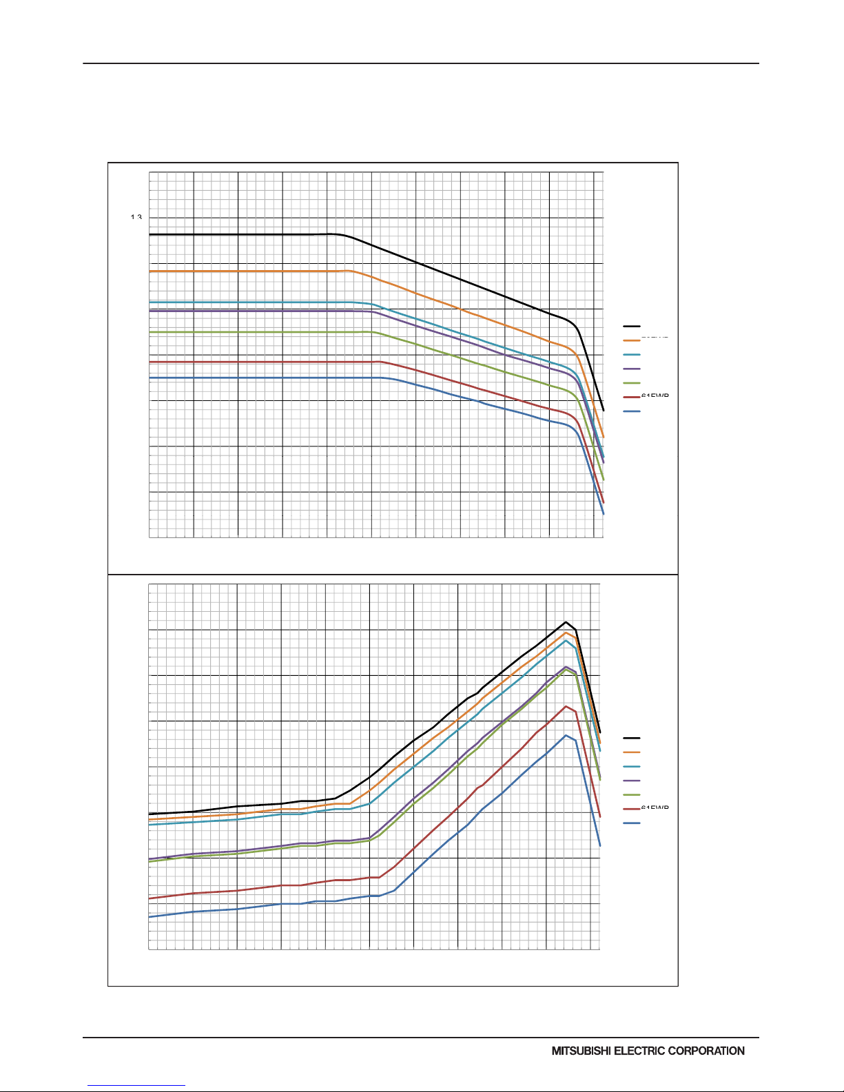
H2i-R2-24
PURY-HP-T(S)KMU,-Y(S)KMU (September 2014)
© 2014 Mitsubishi Electric US, Inc.
7. CAPACITY TABLES
7-1. Correction by Temperature (Standard Performance) in Fahrenheit
1.4
1.2
1.3
1.1
apacity
75FWB
1
tio of Cooling
C
72FWB
69FWB
67FWB
64FWB
0.8
0.9
R
a
61FWB
59FWB
0.7
0.6
23 32 41 50 59 68 77 86 95 104 113
Outdoor Temperature (FDB)
CITY MULTI could have various capacities at different design temperatures. Using the nominal cooling/heating capacity value
and the ratio below, the capacity can be observed at various temperatures.
7-1-1. Cooling Capacity/Power Input with PURY-HP72TKMU-A-H
0.9
1
1.1
1.2
1.3
Ratio of Power Input
75FWB
72FWB
69FWB
67FWB
64FWB
0.5
0.6
0.7
0.8
23.0 32.0 41.0 50.0 59.0 68.0 77.0 86.0 95.0 104.0 113.0
Outdoor Temperature (FDB)
61FWB
59FWB
Page 25
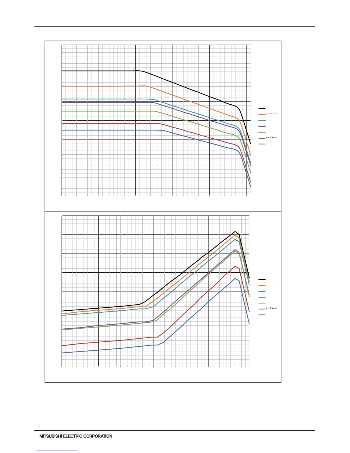
PURY-HP-T(S)KMU,-Y(S)KMU (September 2014)
H2i-R2-25
© 2014 Mitsubishi Electric US, Inc.
7. CAPACITY TABLES
1.4
1.2
1.3
1.1
apacity
75FWB
1
tio of Cooling
C
72FWB
69FWB
67FWB
64FWB
0.8
0.9
R
a
61FWB
59FWB
0.7
0.6
23 32 41 50 59 68 77 86 95 104 113
Outdoor Temperature (FDB)
7-1-2. Cooling Capacity/Power Input with PURY-HP96TKMU-A-H
1.3
1.1
1.2
1
Input
75FWB
0.9
Ratio of Powe
r
72FWB
69FWB
67FWB
64FWB
0.7
0.8
61FWB
59FWB
0.6
0.5
23.0 32.0 41.0 50.0 59.0 68.0 77.0 86.0 95.0 104.0 113.0
Outdoor Temperature (FDB)
Page 26
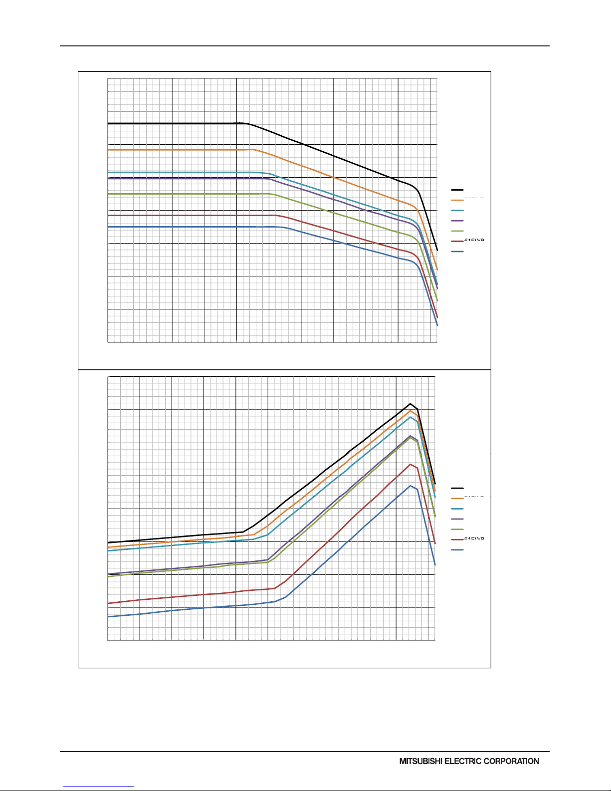
H2i-R2-26
PURY-HP-T(S)KMU,-Y(S)KMU (September 2014)
© 2014 Mitsubishi Electric US, Inc.
1.4
1.2
1.3
1.1
apacity
75FWB
1
tio of Cooling
C
72FWB
69FWB
67FWB
64FWB
0.8
0.9
R
a
61FWB
59FWB
0.7
0.6
23 32 41 50 59 68 77 86 95 104 113
Outdoor Temperature (FDB)
7-1-3. Cooling Capacity/Power Input with PURY-HP144TSKMU-A-H
7. CAPACITY TABLES
1.3
1.1
1.2
1
Input
75FWB
0.9
Ratio of Powe
r
72FWB
69FWB
67FWB
64FWB
0.7
0.8
61FWB
59FWB
0.6
0.5
23.0 32.0 41.0 50.0 59.0 68.0 77.0 86.0 95.0 104.0 113.0
Outdoor Temperature (FDB)
Page 27
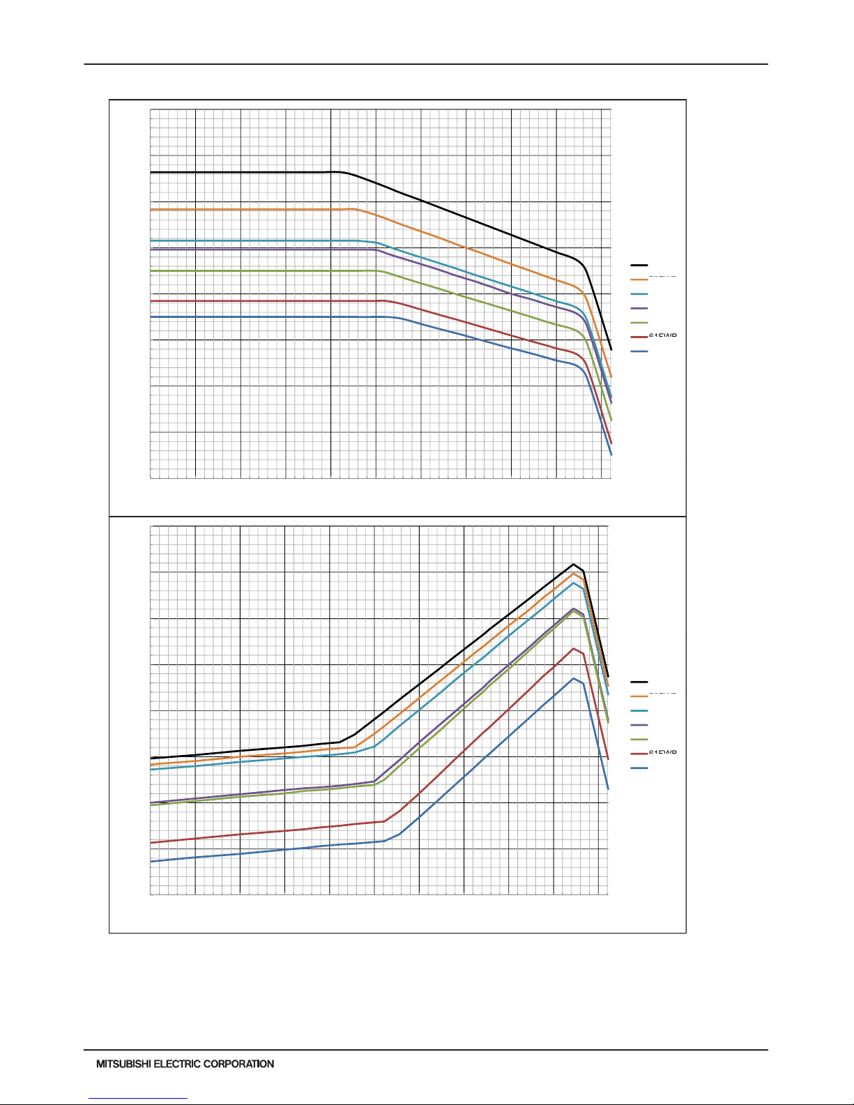
PURY-HP-T(S)KMU,-Y(S)KMU (September 2014)
H2i-R2-27
© 2014 Mitsubishi Electric US, Inc.
1.4
1.2
1.3
1.1
apacity
75FWB
1
tio of Cooling
C
72FWB
69FWB
67FWB
64FWB
0.8
0.9
R
a
61FWB
59FWB
0.7
0.6
23 32 41 50 59 68 77 86 95 104 113
Outdoor Temperature (FDB)
7-1-4. Cooling Capacity/Power Input with PURY-HP192TSKMU-A-H
7. CAPACITY TABLES
1.3
1.1
1.2
1
Input
75FWB
0.9
Ratio of Powe
r
72FWB
69FWB
67FWB
64FWB
0.7
0.8
61FWB
59FWB
0.6
0.5
23.0 32.0 41.0 50.0 59.0 68.0 77.0 86.0 95.0 104.0 113.0
Outdoor Temperature (FDB)
Page 28

H2i-R2-28
PURY-HP-T(S)KMU,-Y(S)KMU (September 2014)
© 2014 Mitsubishi Electric US, Inc.
1.4
1.3
1.1
1.2
apacity
1
tio of Heating
C
59FDB
70FWB
77FWB
81FWB
0.9
R
a
0.8
0.7
-20 -10 0 10 20 30 40 50 60
Outdoor Temperature (FWB)
7-1-5. Heating Capacity/Power Input with PURY-HP72TKMU-A-H
7. CAPACITY TABLES
2.1
2.2
2.3
1.8
1.9
2
1.5
1.6
1.7
Input
1.3
1.4
Ratio of Powe
r
59FDB
70FWB
77FWB
81FWB
1
1.1
1.2
0.7
0.8
0.9
0.5
0.6
-20.0 -10.0 0.0 10.0 20.0 30.0 40.0 50.0 60.0
Outdoor Temperature (FWB)
59FDB
70FDB
77FDB
81FDB
59FDB
70FDB
77FDB
81FDB
59FDB
70FDB
77FDB
81FDB
Page 29
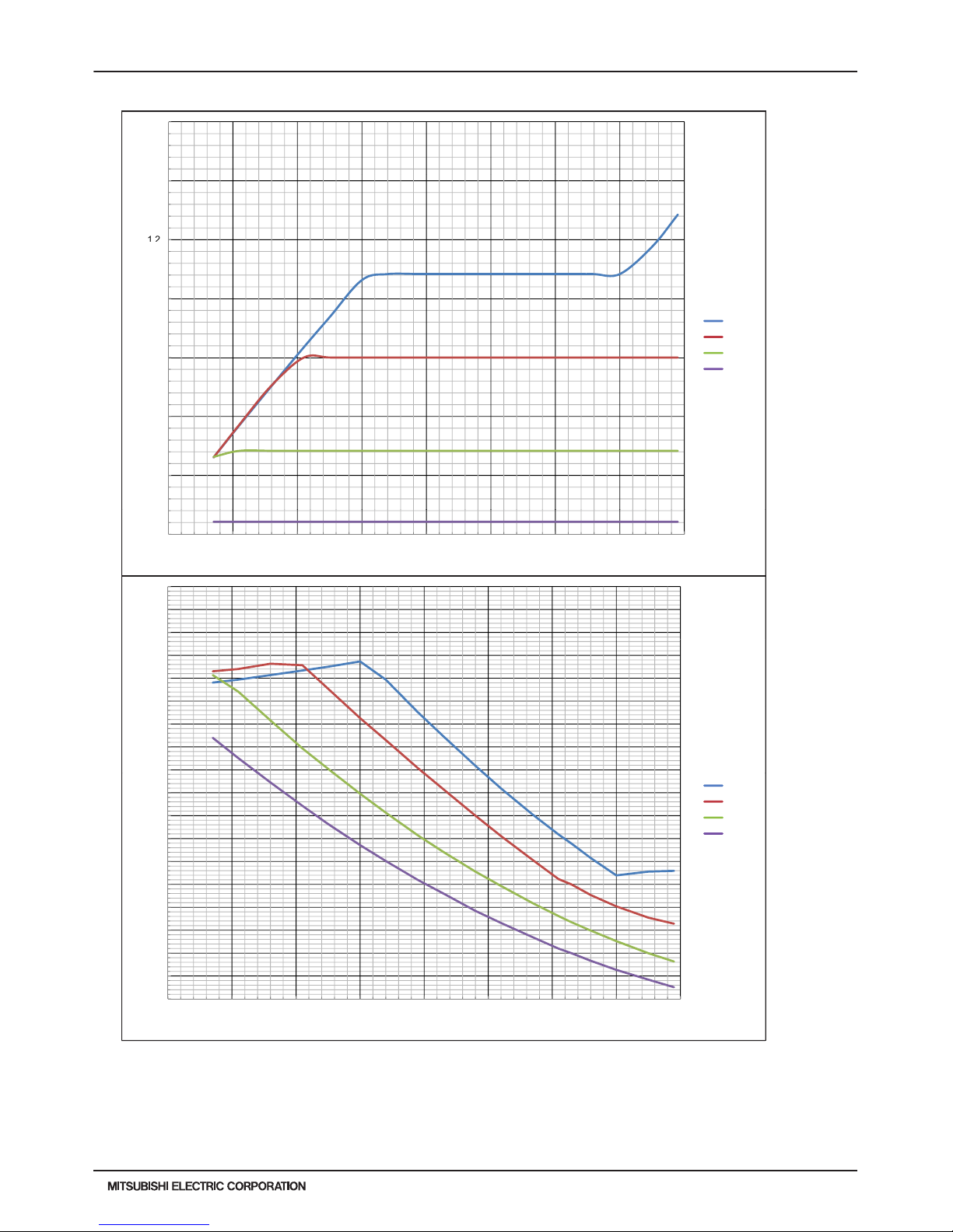
PURY-HP-T(S)KMU,-Y(S)KMU (September 2014)
H2i-R2-29
© 2014 Mitsubishi Electric US, Inc.
1.4
1.3
1.1
1.2
apacity
1
tio of Heating
C
59FDB
70FWB
77FWB
81FWB
0.9
R
a
0.8
0.7
-20 -10 0 10 20 30 40 50 60
Outdoor Temperature (FWB)
7-1-6. Heating Capacity/Power Input with PURY-HP96TKMU-A-H
7. CAPACITY TABLES
2.1
2.2
2.3
1.8
1.9
2
1.5
1.6
1.7
Input
1.3
1.4
Ratio of Powe
r
59FDB
70FWB
77FWB
81FWB
1
1.1
1.2
0.7
0.8
0.9
0.5
0.6
-20.0 -10.0 0.0 10.0 20.0 30.0 40.0 50.0 60.0
Outdoor Temperature (FWB)
59FDB
70FDB
77FDB
81FDB
59FDB
70FDB
77FDB
81FDB
59FDB
70FDB
77FDB
81FDB
Page 30
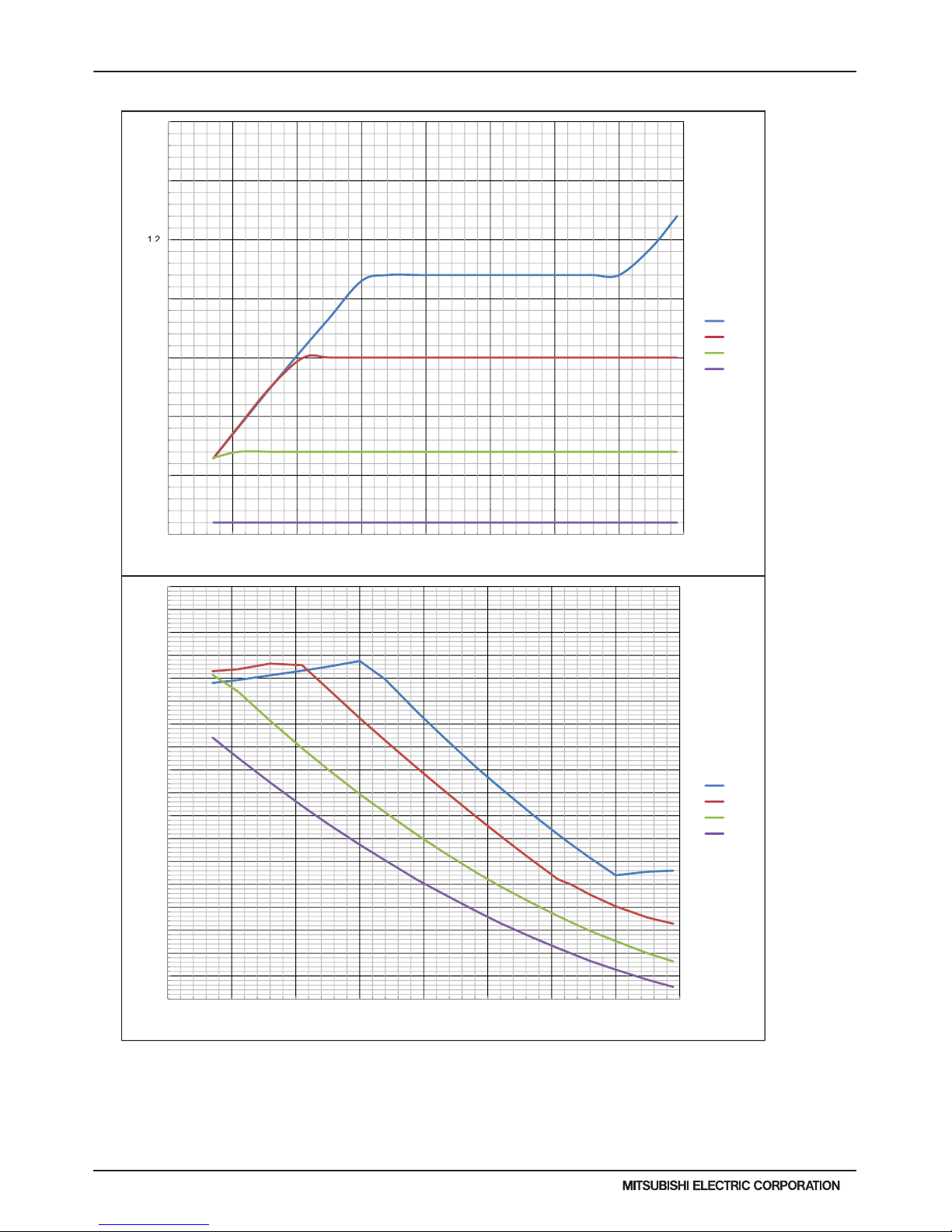
H2i-R2-30
PURY-HP-T(S)KMU,-Y(S)KMU (September 2014)
© 2014 Mitsubishi Electric US, Inc.
1.4
1.3
1.1
1.2
apacity
1
tio of Heating
C
59FDB
70FWB
77FWB
81FWB
0.9
R
a
0.8
0.7
-20 -10 0 10 20 30 40 50 60
Outdoor Temperature (FWB)
7-1-7. Heating Capacity/Power Input with PURY-HP144TSKMU-A-H
7. CAPACITY TABLES
2.1
2.2
2.3
1.8
1.9
2
1.5
1.6
1.7
Input
1.3
1.4
Ratio of Powe
r
59FDB
70FWB
77FWB
81FWB
1
1.1
1.2
0.7
0.8
0.9
0.5
0.6
-20.0 -10.0 0.0 10.0 20.0 30.0 40.0 50.0 60.0
Outdoor Temperature (FWB)
59FDB
70FDB
77FDB
81FDB
59FDB
70FDB
77FDB
81FDB
59FDB
70FDB
77FDB
81FDB
Page 31

PURY-HP-T(S)KMU,-Y(S)KMU (September 2014)
H2i-R2-31
© 2014 Mitsubishi Electric US, Inc.
1.4
1.3
1.1
1.2
apacity
1
tio of Heating
C
59FDB
70FWB
77FWB
81FWB
0.9
R
a
0.8
0.7
-20 -10 0 10 20 30 40 50 60
Outdoor Temperature (FWB)
7-1-8. Heating Capacity/Power Input with PURY-HP192TSKMU-A-H
7. CAPACITY TABLES
2.1
2.2
2.3
1.8
1.9
2
1.5
1.6
1.7
Input
1.3
1.4
Ratio of Powe
r
59FDB
70FWB
77FWB
81FWB
1
1.1
1.2
0.7
0.8
0.9
0.5
0.6
-20.0 -10.0 0.0 10.0 20.0 30.0 40.0 50.0 60.0
Outdoor Temperature (FWB)
59FDB
70FDB
77FDB
81FDB
59FDB
70FDB
77FDB
81FDB
59FDB
70FDB
77FDB
81FDB
Page 32

H2i-R2-32
PURY-HP-T(S)KMU,-Y(S)KMU (September 2014)
© 2014 Mitsubishi Electric US, Inc.
7. CAPACITY TABLES
7-2. Correction by Temperature (High Heating Performance) in Fahrenheit
CITY MULTI could have various capacities at different design temperatures. Using the nominal heating capacity value and the
ratio below, the capacity can be observed at various temperatures.
To select high-heating performance operation, DipSW3-7 must be set to ON. At low ambient temperatures, heating capacity and
power input become higher than those seen in standard operation.
1.4
1.3
1.1
1.2
apacity
1
tio of Heating
C
59FDB
70FWB
77FWB
81FWB
0.9
R
a
0.8
0.7
-20 -10 0 10 20 30 40 50 60
Outdoor Temperature (FWB)
7-2-1. Heating Capacity/Power Input (High Heat Performance) with PURY-HP72TKMU-A-H
2.1
2.2
2.3
1.8
1.9
2
1.5
1.6
1.7
Input
1.3
1.4
Ratio of Powe
r
59FDB
70FWB
77FWB
81FWB
1
1.1
1.2
0.7
0.8
0.9
0.5
0.6
-20.0 -10.0 0.0 10.0 20.0 30.0 40.0 50.0 60.0
Outdoor Temperature (FWB)
59FDB
70FDB
77FDB
81FDB
59FDB
70FDB
77FDB
81FDB
59FDB
70FDB
77FDB
81FDB
Page 33

PURY-HP-T(S)KMU,-Y(S)KMU (September 2014)
H2i-R2-33
© 2014 Mitsubishi Electric US, Inc.
7. CAPACITY TABLES
1.4
1.3
1.1
1.2
apacity
1
tio of Heating
C
59FDB
70FWB
77FWB
81FWB
0.9
R
a
0.8
0.7
-20 -10 0 10 20 30 40 50 60
Outdoor Temperature (FWB)
7-2-2. Heating Capacity/Power Input (High Heat Performance) with PURY-HP96TKMU-A-H
2.1
2.2
2.3
1.8
1.9
2
1.5
1.6
1.7
Input
1.3
1.4
Ratio of Powe
r
59FDB
70FWB
77FWB
81FWB
1
1.1
1.2
0.7
0.8
0.9
0.5
0.6
-20.0 -10.0 0.0 10.0 20.0 30.0 40.0 50.0 60.0
Outdoor Temperature (FWB)
59FDB
70FDB
77FDB
81FDB
59FDB
70FDB
77FDB
81FDB
59FDB
70FDB
77FDB
81FDB
Page 34

H2i-R2-34
PURY-HP-T(S)KMU,-Y(S)KMU (September 2014)
© 2014 Mitsubishi Electric US, Inc.
1.4
1.3
1.1
1.2
apacity
1
tio of Heating
C
59FDB
70FWB
77FWB
81FWB
0.9
R
a
0.8
0.7
-20 -10 0 10 20 30 40 50 60
Outdoor Temperature (FWB)
7-2-3. Heating Capacity/Power Input (High Heat Performance) with PURY-HP144TSKMU-A-H
7. CAPACITY TABLES
2.1
2.2
2.3
1.8
1.9
2
1.5
1.6
1.7
Input
1.3
1.4
Ratio of Powe
r
59FDB
70FWB
77FWB
81FWB
1
1.1
1.2
0.7
0.8
0.9
0.5
0.6
-20.0 -10.0 0.0 10.0 20.0 30.0 40.0 50.0 60.0
Outdoor Temperature (FWB)
59FDB
70FDB
77FDB
81FDB
59FDB
70FDB
77FDB
81FDB
59FDB
70FDB
77FDB
81FDB
Page 35

PURY-HP-T(S)KMU,-Y(S)KMU (September 2014)
H2i-R2-35
© 2014 Mitsubishi Electric US, Inc.
1.4
1.3
1.1
1.2
apacity
1
tio of Heating
C
59FDB
70FWB
77FWB
81FWB
0.9
R
a
0.8
0.7
-20 -10 0 10 20 30 40 50 60
Outdoor Temperature (FWB)
7-2-4. Heating Capacity/Power Input (High Heat Performance) with PURY-HP192TSKMU-A-H
7. CAPACITY TABLES
2.1
2.2
2.3
1.8
1.9
2
1.5
1.6
1.7
Input
1.3
1.4
Ratio of Powe
r
59FDB
70FWB
77FWB
81FWB
1
1.1
1.2
0.7
0.8
0.9
0.5
0.6
-20.0 -10.0 0.0 10.0 20.0 30.0 40.0 50.0 60.0
Outdoor Temperature (FWB)
59FDB
70FDB
77FDB
81FDB
59FDB
70FDB
77FDB
81FDB
59FDB
70FDB
77FDB
81FDB
Page 36

H2i-R2-36
PURY-HP-T(S)KMU,-Y(S)KMU (September 2014)
© 2014 Mitsubishi Electric US, Inc.
7. CAPACITY TABLES
7-3. Correction by Temperature (Intelligent Heat Performance) in Fahrenheit
CITY MULTI could have various capacities at different design temperatures. Using the nominal cooling/heating capacity value
and the ratio below, the capacity can be observed at various temperatures.
1.4
1.3
1.1
1.2
apacity
1
tio of Heating
C
59FDB
70FWB
77FWB
81FWB
0.9
R
a
0.8
0.7
-20 -10 0 10 20 30 40 50 60
Outdoor Temperature (FWB)
7-3-1. Heating Capacity/Power Input (Intelligent Heat Performance) with PURY-HP72TKMU-A-H
2.1
2.2
2.3
1.8
1.9
2
1.5
1.6
1.7
Input
1.3
1.4
Ratio of Powe
r
59FDB
70FWB
77FWB
81FWB
1
1.1
1.2
0.7
0.8
0.9
0.5
0.6
-20.0 -10.0 0.0 10.0 20.0 30.0 40.0 50.0 60.0
Outdoor Temperature (FWB)
59FDB
70FDB
77FDB
81FDB
59FDB
70FDB
77FDB
81FDB
59FDB
70FDB
77FDB
81FDB
Page 37
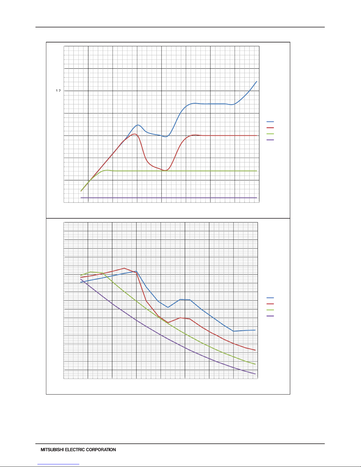
PURY-HP-T(S)KMU,-Y(S)KMU (September 2014)
H2i-R2-37
© 2014 Mitsubishi Electric US, Inc.
7. CAPACITY TABLES
1.4
1.3
1.1
1.2
apacity
1
tio of Heating
C
59FDB
70FWB
77FWB
81FWB
0.9
R
a
0.8
0.7
-20 -10 0 10 20 30 40 50 60
Outdoor Temperature (FWB)
7-3-2. Heating Capacity/Power Input (Intelligent Heat Performance) with PURY-HP96TKMU-A-H
2.1
2.2
2.3
1.8
1.9
2
1.5
1.6
1.7
Input
1.3
1.4
Ratio of Powe
r
59FDB
70FWB
77FWB
81FWB
1
1.1
1.2
0.7
0.8
0.9
0.5
0.6
-20.0 -10.0 0.0 10.0 20.0 30.0 40.0 50.0 60.0
Outdoor Temperature (FWB)
59FDB
70FDB
77FDB
81FDB
59FDB
70FDB
77FDB
81FDB
59FDB
70FDB
77FDB
81FDB
Page 38
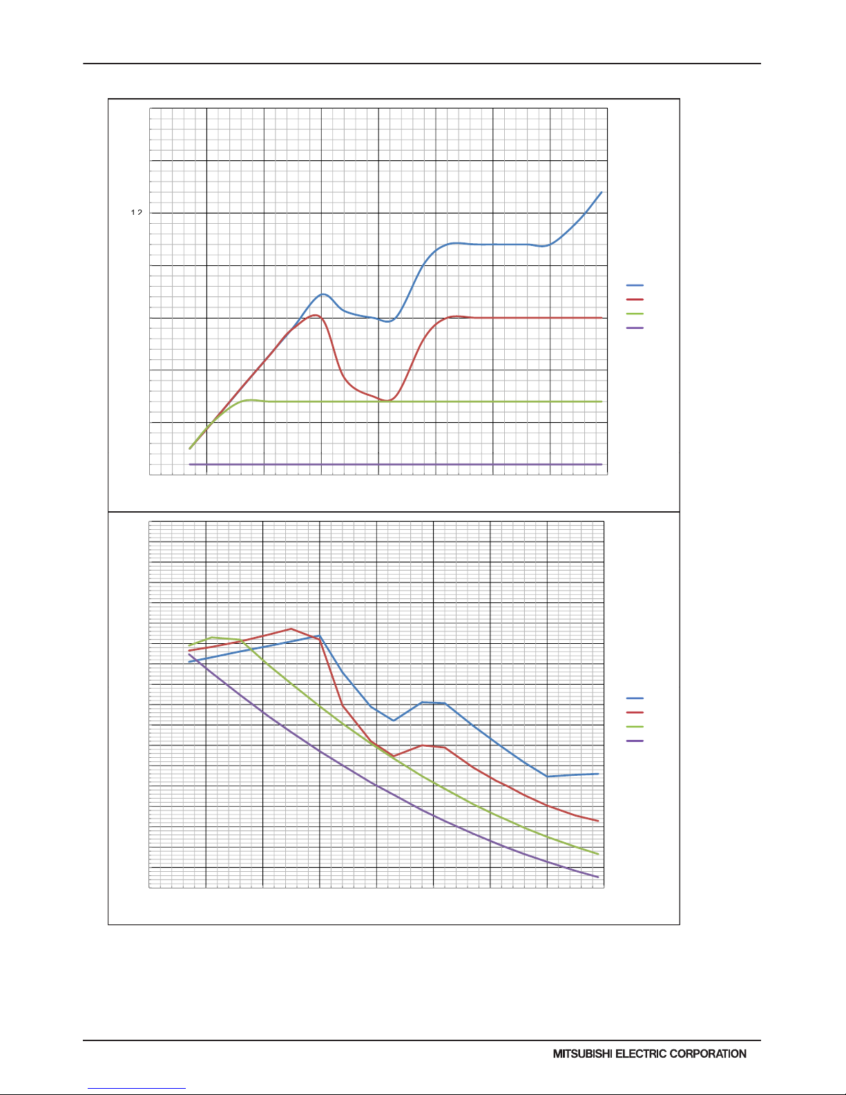
H2i-R2-38
PURY-HP-T(S)KMU,-Y(S)KMU (September 2014)
© 2014 Mitsubishi Electric US, Inc.
1.4
1.3
1.1
1.2
apacity
1
tio of Heating
C
59FDB
70FWB
77FWB
81FWB
0.9
R
a
0.8
0.7
-20 -10 0 10 20 30 40 50 60
Outdoor Temperature (FWB)
7-3-3. Heating Capacity/Power Input (Intelligent Heat Performance) with PURY-HP144TSKMU-A-H
7. CAPACITY TABLES
2.1
2.2
2.3
1.8
1.9
2
1.5
1.6
1.7
Input
1.3
1.4
Ratio of Powe
r
59FDB
70FWB
77FWB
81FWB
1
1.1
1.2
0.7
0.8
0.9
0.5
0.6
-20.0 -10.0 0.0 10.0 20.0 30.0 40.0 50.0 60.0
Outdoor Temperature (FWB)
59FDB
70FDB
77FDB
81FDB
59FDB
70FDB
77FDB
81FDB
59FDB
70FDB
77FDB
81FDB
Page 39

PURY-HP-T(S)KMU,-Y(S)KMU (September 2014)
H2i-R2-39
© 2014 Mitsubishi Electric US, Inc.
1.4
1.3
1.1
1.2
apacity
1
tio of Heating
C
59FDB
70FWB
77FWB
81FWB
0.9
R
a
0.8
0.7
-20 -10 0 10 20 30 40 50 60
Outdoor Temperature (FWB)
7-3-4. Heating Capacity/Power Input (Intelligent Heat Performance) with PURY-HP192TSKMU-A-H
7. CAPACITY TABLES
2.1
2.2
2.3
1.8
1.9
2
1.5
1.6
1.7
Input
1.3
1.4
Ratio of Powe
r
59FDB
70FWB
77FWB
81FWB
1
1.1
1.2
0.7
0.8
0.9
0.5
0.6
-20.0 -10.0 0.0 10.0 20.0 30.0 40.0 50.0 60.0
Outdoor Temperature (FWB)
59FDB
70FDB
77FDB
81FDB
59FDB
70FDB
77FDB
81FDB
59FDB
70FDB
77FDB
81FDB
Page 40
H2i-R2-40
PURY-HP-T(S)KMU,-Y(S)KMU (September 2014)
© 2014 Mitsubishi Electric US, Inc.
7. CAPACITY TABLES
7-4. Correction by Temperature/Total Indoor in Fahrenheit
7-4-1. Cooling Capacity with PURY-HP72TKMU-A-H
6. CAPACITY TABLES
DATA U10
H2i R2
PURY-HP72TKMU-A-H TC:Total Capacity(BTU), PI:Power Input(BTU)
Combination Outdoor Indoor air temp.
(%) air temp. 71°F D.B. 73°F D.B. 77°F D.B. 80°F D.B. 82°F D.B. 86°F D.B. 90°F D.B.
59°F W.B. 61°F W.B. 64°F W.B. 67°F W.B. 69°F W.B. 72°F W.B. 75°F W.B.
°F D.B. TC PI TC PI TC PI TC PI TC PI TC PI TC PI
150 23.0 74900 10200 77700 10900 82800 12300 86400 12400 87900 13700 93300 13900 99600 14100
32.0 74900 10300 77700 11000 82800 12500 86400 12600 87900 13800 93300 14000 99600 14300
41.0 74900 10500 77700 11200 82800 12600 86400 12700 87900 14000 93300 14200 99600 14400
50.0 74900 10600 77700 11300 82800 12800 86400 12900 87900 14100 93300 14300 99600 14600
54.0 74900 10700 77700 11400 82800 12900 86400 13000 87900 14200 93300 14400 99600 14600
57.0 74900 10700 77700 11500 82800 12900 86400 13000 87900 14200 93300 14400 99600 14700
61.0 74900 10800 77700 11500 82800 13000 86400 13100 87900 14300 93300 14500 99600 14700
64.0 74900 10900 77700 11600 82800 13000 86400 13100 87900 14400 93300 14600 99100 15000
68.0 74900 10900 77700 11700 82800 13100 86300 13200 87600 14600 92300 15100 97800 15600
70.0 74900 11000 77700 11700 82500 13300 85800 13600 87000 14900 91700 15400 97100 15900
73.0 74600 11200 77100 12100 81700 13800 85000 14100 86200 15400 90700 15800 96100 16400
77.0 73700 11900 76200 12800 80600 14500 83900 14700 85100 16000 89500 16500 94800 17000
81.0 72800 12600 75200 13500 79600 15200 82800 15400 84000 16600 88300 17100 93500 17600
84.0 72100 13100 74400 14100 78800 15700 82000 15900 83100 17100 87300 17500 92500 18000
88.0 71200 13800 73500 14800 77800 16400 80900 16600 82000 17700 86100 18200 91200 18600
90.0 70700 14100 73000 15100 77200 16700 80300 16900 81500 18000 85500 18500 90500 18900
91.0 70500 14300 72700 15300 77000 16900 80000 17100 81200 18200 85200 18600 90200 19100
95.0 69500 15000 71700 16000 75900 17600 78800 17700 80100 18800 83900 19200 88900 19700
99.0 68600 15700 70800 16700 74900 18300 77900 18400 79000 19500 82700 19800 87600 20200
102.0 67900 16200 70000 17300 74100 18800 77100 18900 78100 19900 81800 20300 86600 20700
104.0 67500 16500 69500 17600 73600 19100 76600 19200 77600 20200 81200 20600 85900 21000
108.0 66600 17200 68500 18400 72500 19800 75500 19900 76500 20900 79900 21200 84600 21600
110.0 64700 17000 66700 18200 70600 19600 73600 19700 74600 20600 78000 21000 82600 21300
115.0 51300 12900 53300 14100 57200 15500 60200 15600 61200 16600 64600 16900 69200 17300
140 23.0 73900 10100 76600 10900 81600 12300 85200 12400 86700 13600 92000 13800 98300 14100
32.0 73900 10300 76600 11000 81600 12400 8520 0 12500 8670 0 13800 92 000 14000 98 300 14200
41.0 73900 10400 76600 11200 81600 12600 8520 0 12700 8670 0 13900 92 000 14100 98 300 14400
50.0 73900 10600 76600 11300 81600 12700 8520 0 12800 8670 0 14100 92 000 14300 98 300 14500
54.0 73900 10600 76600 11400 81600 12800 8520 0 12900 8670 0 14100 92 000 14300 98 300 14600
57.0 73900 10700 76600 11400 81600 12900 8520 0 13000 8670 0 14200 92 000 14400 98 300 14600
61.0 73900 10800 76600 11500 81600 12900 8520 0 13000 8670 0 14200 92 000 14500 98 300 14700
64.0 73900 10800 76600 11500 81600 13000 8520 0 13100 8670 0 14300 92 000 14500 97 700 15000
68.0 73900 10900 76600 11600 81600 13100 8510 0 13200 8640 0 14500 91 000 15000 96 400 15600
70.0 73900 10900 76600 11600 81400 13300 8460 0 13500 8580 0 14800 90 400 15300 95 800 15900
73.0 73600 11200 76100 12000 80600 13800 8380 0 14000 8500 0 15300 89 500 15800 94 800 16300
77.0 72700 11800 75100 12700 79500 14400 8270 0 14700 8390 0 15900 88 300 16400 93 500 16900
81.0 71800 12500 74100 13500 78500 15100 8170 0 15300 8280 0 16500 87 100 17000 92 200 17500
84.0 71100 13000 73400 14000 77700 15600 8080 0 15800 8200 0 17000 86 100 17500 91 200 17900
88.0 70200 13700 72400 14700 76700 16300 7980 0 16500 8090 0 17700 84 900 18100 89 900 18500
90.0 69700 14100 72000 15100 76200 16700 7920 0 16800 8040 0 18000 84 300 18400 89 300 18800
91.0 69500 14200 71700 15300 75900 16800 7890 0 17000 8010 0 18100 84 000 18500 88 900 19000
95.0 68600 14900 70700 16000 74900 17500 7770 0 17700 7900 0 18800 82 800 19200 87 700 19600
99.0 67700 15600 69800 16700 73800 18200 7680 0 18300 7790 0 19400 81 600 19800 86 400 20200
102.0 67000 16100 69000 1720 0 73000 1870 0 76000 18 800 77000 19 900 80600 20200 85400 20600
104.0 66500 16500 68600 1760 0 72500 1900 0 75500 19 200 76500 20 200 80000 20500 84800 20900
108.0 65600 17100 67600 1830 0 71500 1970 0 74400 19 800 75400 20 800 78800 21100 83500 21500
110.0 63800 16900 65800 1810 0 69600 1950 0 72600 19 600 73500 20 600 76900 20900 81500 21300
115.0 50600 12900 52500 1400 0 56400 1540 0 59300 15 500 60300 16 500 63700 16900 68300 17200
130 23.0 72700 10100 75400 10800 80300 12200 83900 12300 85300 13600 90500 13800 96700 14000
32.0 72700 10200 75400 11000 80300 12400 8390 0 12500 8530 0 13700 90 500 13900 96 700 14100
41.0 72700 10400 75400 11100 80300 12500 8390 0 12600 8530 0 13900 90 500 14100 96 700 14300
50.0 72700 10500 75400 11300 80300 12700 8390 0 12800 8530 0 14000 90 500 14200 96 700 14400
54.0 72700 10600 75400 11300 80300 12800 8390 0 12900 8530 0 14100 90 500 14300 96 700 14500
57.0 72700 10600 75400 11400 80300 12800 8390 0 12900 8530 0 14100 90 500 14300 96 700 14500
61.0 72700 10700 75400 11400 80300 12900 8390 0 13000 8530 0 14200 90 500 14400 96 700 14600
64.0 72700 10800 75400 11500 80300 12900 8390 0 13000 8530 0 14200 90 500 14400 96 100 14900
68.0 72700 10800 75400 11600 80300 13000 8380 0 13100 8500 0 14400 89 600 14900 94 900 15500
70.0 72700 10900 75400 11600 80100 13200 8330 0 13500 8450 0 14800 89 000 15200 94 300 15800
73.0 72400 11100 74900 12000 79300 13700 8250 0 14000 8370 0 15200 88 100 15700 93 300 16200
77.0 71500 11800 73900 12700 78300 14400 8140 0 14600 8260 0 15900 86 900 16300 92 000 16800
81.0 70600 12500 73000 13400 77300 15100 8040 0 15300 8150 0 16500 85 700 16900 90 800 17400
84.0 70000 13000 72200 13900 76500 15600 7960 0 15800 8070 0 17000 84 800 17400 89 800 17900
88.0 69100 13700 71300 14600 75500 16200 7850 0 16400 7960 0 17600 83 600 18000 88 500 18500
90.0 68600 14000 70800 15000 75000 16600 7800 0 16700 7910 0 17900 83 000 18300 87 900 18700
91.0 68400 14200 70600 15200 74700 16800 7770 0 16900 7880 0 18100 82 700 18500 87 500 18900
95.0 67500 14900 69600 15900 73700 17400 7650 0 17600 7770 0 18700 81 500 19100 86 300 19500
99.0 66600 15500 68700 16600 72700 18100 7560 0 18200 7670 0 19300 80 300 19700 85 000 20100
102.0 65900 16100 67900 1710 0 71900 1860 0 74800 18 700 75800 19 800 79400 20100 84000 20500
104.0 65500 16400 67500 1750 0 71400 1900 0 74300 19 100 75300 20 100 78800 20400 83400 20800
108.0 64600 17100 66500 1820 0 70400 1960 0 73300 19 700 74200 20 700 77600 21100 82200 21400
110.0 62800 16900 64700 1800 0 68500 1940 0 71400 19 500 72400 20 500 75700 20800 80200 21200
115.0 49800 12800 51700 1400 0 55500 1540 0 58400 15 500 59400 16 400 62700 16800 67200 17100
kcal/h=kW x 860 , BTU/h = kW x 3,412
Page 41

PURY-HP-T(S)KMU,-Y(S)KMU (September 2014)
H2i-R2-41
© 2014 Mitsubishi Electric US, Inc.
7. CAPACITY TABLES
7-4-1. Cooling Capacity with PURY-HP72TKMU-A-H (cont.)
6. CAPACITY TABLES
DATA U10
120 23.0 71400 10000 74000 10800 78900 12200 82400 12300 83800 13500 88900 13700 95000 13900
32.0 71400 10200 74000 10900 78900 12300 82400 12400 83800 13700 88900 13900 95000 14100
41.0 71400 10300 74000 11100 78900 12500 82400 12600 83800 13800 88900 14000 95000 14200
50.0 71400 10500 74000 11200 78900 12600 82400 12700 83800 13900 88900 14100 95000 14400
54.0 71400 10500 74000 11300 78900 12700 82400 12800 83800 14000 88900 14200 95000 14400
57.0 71400 10600 74000 11300 78900 12700 82400 12800 83800 14100 88900 14300 95000 14500
61.0 71400 10700 74000 11400 78900 12800 82400 12900 83800 14100 88900 14300 95000 14500
64.0 71400 10700 74000 11400 78900 12900 82400 13000 83800 14200 88900 14400 94400 14800
68.0 71400 10800 74000 11500 78900 12900 82300 13100 83500 14400 88000 14900 93200 15400
70.0 71400 10800 74000 11500 78600 13100 81800 13400 83000 14700 87400 15200 92600 15700
73.0 71100 11000 73500 11900 77900 13600 81000 13900 82200 15200 86500 15600 91600 16200
77.0 70200 11700 72600 12600 76900 14300 80000 14500 81100 15800 85300 16200 90400 16700
81.0 69400 12400 71700 13300 75900 15000 78900 15200 80100 16400 84200 16800 89100 17300
84.0 68700 12900 70900 13900 75100 15500 78100 15700 79300 16900 83300 17300 88200 17800
88.0 67800 13600 70000 14600 74100 16200 77100 16300 78200 17500 82100 17900 86900 18400
90.0 67400 13900 69600 14900 73600 16500 76600 16700 77700 17800 81500 18200 86300 18700
91.0 67200 14100 69300 15100 73400 16700 76300 16800 77400 18000 81200 18400 86000 18800
95.0 66300 14800 68400 15800 72400 17300 75100 17500 76300 18600 80000 19000 84700 19400
99.0 65400 15500 67400 16500 71400 18000 74300 18100 75300 19200 78900 19600 83500 20000
102.0 64700 16000 66700 17100 70600 18500 73500 18600 74500 19700 78000 20000 82500 20400
104.0 64300 16300 66300 17400 70100 18900 73000 19000 74000 20000 77400 20300 81900 20700
108.0 63400 17000 65300 18100 69100 19500 72000 19600 72900 20600 76200 21000 80700 21300
110.0 61700 16800 63600 17900 67300 19300 70100 19400 71100 20400 74300 20700 78800 21100
115.0 48900 12800 50800 13900 54500 15300 57400 15400 58300 16400 61600 16700 66000 17100
110 23.0 70000 10000 72500 10700 77300 12100 80700 12200 82100 13400 87100 13600 93100 13900
32.0 70000 10100 72500 10800 77300 12300 80700 12400 82100 13600 87100 13800 93100 14000
41.0 70000 10300 72500 11000 77300 12400 80700 12500 82100 13700 87100 13900 93100 14100
50.0 70000 10400 72500 11100 77300 12600 80700 12700 82100 13900 87100 14100 93100 14300
54.0 70000 10500 72500 11200 77300 12600 80700 12700 82100 13900 87100 14100 93100 14300
57.0 70000 10500 72500 11300 77300 12700 80700 12800 82100 14000 87100 14200 93100 14400
61.0 70000 10600 72500 11300 77300 12700 80700 12800 82100 14000 87100 14200 93100 14500
64.0 70000 10700 72500 11400 77300 12800 80700 12900 82100 14100 87100 14300 92500 14700
68.0 70000 10700 72500 11400 77300 12900 80600 13000 81800 14300 86200 14800 91300 15300
70.0 70000 10700 72500 11500 77100 13100 80100 13300 81300 14600 85600 15100 90700 15600
73.0 69700 11000 72000 11900 76300 13600 79400 13800 80500 15100 84800 15600 89800 16100
77.0 68800 11700 71100 12600 75300 14200 78400 14500 79500 15700 83600 16200 88600 16700
81.0 68000 12300 70200 13300 74400 14900 77400 15100 78500 16300 82500 16800 87300 17200
84.0 67300 12800 69500 13800 73600 15400 76600 15600 77700 16800 81600 17200 86400 17700
88.0 66500 13500 68600 14500 72600 16100 75600 16300 76600 17400 80400 17800 85200 18300
90.0 66000 13900 68200 14800 72200 16400 75000 16600 76100 17700 79900 18100 84600 18600
91.0 65800 14000 67900 15000 71900 16600 74800 16800 75800 17900 79600 18300 84300 18700
95.0 65000 14700 67000 15700 70900 17300 73600 17400 74800 18500 78400 18900 83000 19300
99.0 64100 15400 66100 16400 69900 17900 72800 18000 73800 19100 77300 19500 81800 19900
102.0 63500 15900 65400 17000 69200 18400 72000 18500 73000 19600 76400 19900 80900 20300
104.0 63000 16200 64900 17300 68700 18800 71500 18900 72500 19900 75800 20200 80300 20600
108.0 62200 16900 64000 18000 67700 19400 70500 19500 71400 20500 74700 20800 79100 21200
110.0 60400 16700 62300 17800 66000 19200 68700 19300 69600 20300 72800 20600 77200 21000
115.0 47900 12700 49800 13800 53400 15200 56200 15300 57100 16300 60300 16600 64700 17000
100 23.0 68400 9900 70900 10600 75600 12000 78900 12100 80300 13400 85200 13600 91000 13800
32.0 68400 10100 70900 10800 75600 12200 78900 12300 80300 13500 85200 13700 91000 13900
41.0 68400 10200 70900 10900 75600 12300 78900 12400 80300 13600 85200 13800 91000 14100
50.0 68400 10400 70900 11100 75600 12500 78900 12600 80300 13800 85200 14000 91000 14200
54.0 68400 10400 70900 11100 75600 12600 78900 12700 80300 13800 85200 14000 91000 14300
57.0 68400 10500 70900 11200 75600 12600 78900 12700 80300 13900 85200 14100 91000 14300
61.0 68400 10500 70900 11300 75600 12700 78900 12800 80300 14000 85200 14200 91000 14400
64.0 68400 10600 70900 11300 75600 12700 78900 12800 80300 14000 85200 14200 90500 14700
68.0 68400 10700 70900 11400 75600 12800 78800 12900 80000 14200 84300 14700 89300 15200
70.0 68400 10700 70900 11400 75300 13000 78400 13200 79500 14500 83700 15000 88700 15500
73.0 68100 10900 70400 11800 74600 13500 77600 13700 78700 15000 82900 15500 87800 16000
77.0 67300 11600 69600 12500 73700 14200 76600 14400 77700 15600 81700 16100 86600 16600
81.0 66500 12300 68700 13200 72700 14800 75600 15000 76700 16200 80600 16700 85400 17100
84.0 65800 12800 68000 13700 72000 15300 74900 15500 75900 16700 79800 17100 84500 17600
88.0 65000 13400 67100 14400 71000 16000 73900 16200 74900 17300 78600 17700 83300 18200
90.0 64600 13800 66600 14800 70500 16300 73400 16500 74400 17600 78100 18000 82700 18400
91.0 64300 14000 66400 14900 70300 16500 73100 16700 74100 17800 77800 18200 82400 18600
95.0 63500 14600 65500 15600 69300 17200 72000 17300 73100 18400 76700 18800 81200 19200
99.0 62700 15300 64600 16300 68400 17800 71100 17900 72100 19000 75600 19400 80000 19800
102.0 62000 15800 63900 16900 67700 18300 70400 18400 71400 19500 74700 19800 79100 20200
104.0 61600 16100 63500 17200 67200 18600 69900 18800 70900 19800 74100 20100 78500 20500
108.0 60800 16800 62600 17900 66200 19300 68900 19400 69800 20400 73000 20700 77300 21100
110.0 59100 16600 60900 17700 64500 19100 67200 19200 68100 20100 71200 20500 75500 20800
115.0 46900 12600 48700 13700 52300 15100 55000 15200 55900 16200 59000 16500 63200 16900
PURY-HP72TKMU-A-H TC:Total Capacity(BTU), PI:Power Input(BTU)
Combination Outdoor Indoor air temp.
(%) air temp. 71°F D.B. 73°F D.B. 77°F D.B. 80°F D.B. 82°F D.B. 86°F D.B. 90°F D.B.
59°F W.B. 61°F W.B. 64°F W.B. 67°F W.B. 69°F W.B. 72°F W.B. 75°F W.B.
°F D.B. T C PI TC PI TC PI TC PI TC PI TC PI TC PI
kcal/h=kW x 860 , BTU/h = kW x 3,412
Page 42

H2i-R2-42
PURY-HP-T(S)KMU,-Y(S)KMU (September 2014)
© 2014 Mitsubishi Electric US, Inc.
7. CAPACITY TABLES
7-4-1. Cooling Capacity with PURY-HP72TKMU-A-H (cont.)
6. CAPACITY TABLES
DATA U10
H2i R2
90 23.0 61600 8800 63800 9500 68000 10700 71000 10800 72200 11900 76700 12100 81900 12300
32.0 61600 9000 63800 9600 68000 10800 71000 10900 7220 0 12000 76 600 12200 81 900 12400
41.0 61600 9100 63800 9700 68000 11000 71000 11100 7220 0 12100 76 600 12300 81 900 12500
50.0 61600 9200 63800 9900 68000 11100 71000 11200 7220 0 12300 76 600 12400 81 900 12600
54.0 61600 9300 63800 9900 68000 11200 71000 11300 7220 0 12300 76 700 12500 81 900 12700
57.0 61600 9300 63800 10000 68000 1120 0 71000 1130 0 72200 12 400 76700 12 500 81900 12700
61.0 61600 9400 63800 10000 68000 1130 0 71000 1140 0 72200 12 400 76700 12 600 81900 12800
64.0 61600 9400 63800 10100 68000 1130 0 71000 1140 0 72200 12 500 76700 12 600 81400 13000
68.0 61600 9500 63800 10100 68000 1140 0 70900 1150 0 72000 12 700 75800 13 100 80300 13600
70.0 61600 9500 63800 10100 67800 1160 0 70500 1180 0 71500 12 900 75300 13 300 79800 13800
73.0 61300 9700 63400 10500 67100 1200 0 69800 1220 0 70800 13 300 74600 13 800 79000 14200
77.0 60600 10300 62600 11100 66300 12600 6900 0 12800 6990 0 13900 73 600 14300 77 900 14700
81.0 59800 10900 61800 11700 65400 13200 6810 0 13400 6900 0 14400 72 600 14800 76 800 15200
84.0 59200 11400 61200 12200 64800 13600 6740 0 13800 6830 0 14800 71 800 15200 76 000 15600
88.0 58500 12000 60400 12800 63900 14200 6650 0 14400 6740 0 15400 70 800 15800 75 000 16200
90.0 58100 12300 60000 13100 63500 14500 6600 0 14700 6700 0 15700 70 300 16000 74 400 16400
91.0 57900 12400 59800 13300 63300 14700 6580 0 14800 6670 0 15800 70 000 16200 74 100 16600
95.0 57200 13000 59000 13900 62400 15300 6480 0 15400 6580 0 16300 69 000 16700 73 100 17100
99.0 56400 13600 58200 14500 61500 15800 6400 0 16000 6490 0 16900 68 000 17200 72 000 17600
102.0 55800 14100 57500 15000 60900 16300 63400 16400 64200 17300 67200 17600 71200 18000
104.0 55400 14400 57100 15300 60500 16600 62900 16700 63800 17600 66700 17900 70600 18200
108.0 54700 14900 56300 15900 59600 17200 62000 17300 62900 18100 65700 18400 69600 18700
110.0 53200 14800 54800 15800 58000 17000 60500 17100 61300 17900 64100 18200 67900 18500
115.0 42200 11200 43800 12200 47000 13500 49500 13500 50300 14400 53100 14700 56900 15000
80 23.0 54700 7800 56700 8400 60500 9500 63100 9500 64200 10500 68100 10700 72800 10800
32.0 54700 7900 56700 8500 60500 9600 63100 9700 64200 10600 68100 10800 72800 10900
41.0 54700 8000 56700 8600 60500 9700 63100 9800 64200 10700 68100 10900 72800 11100
50.0 54700 8100 56700 8700 60500 9800 63100 9900 64200 10800 68100 11000 72800 11200
54.0 54700 8200 56700 8800 60500 9900 63100 9900 64200 10900 68100 11000 72800 11200
57.0 54700 8200 56700 8800 60500 9900 63100 10000 64200 10900 68100 11100 72800 11200
61.0 54700 8300 56700 8800 60500 10000 63100 10000 64200 11000 68100 11100 72800 11300
64.0 54700 8300 56700 8900 60500 10000 63100 10100 64200 11000 68100 11200 72400 11500
68.0 54700 8400 56700 8900 60500 10100 63100 10200 64000 11200 67400 11600 71400 12000
70.0 54700 8400 56700 9000 60300 10200 62700 10400 63600 11400 67000 11800 70900 12200
73.0 54500 8600 56300 9300 59700 10600 62100 10800 63000 11800 66300 12200 70200 12600
77.0 53800 9100 55600 9800 58900 11100 61300 11300 62200 12300 65400 12600 69300 13000
81.0 53200 9600 54900 10400 58200 11600 60500 11800 61400 12700 64500 13100 68300 13500
84.0 52700 10000 54400 1080 0 57600 12 000 59900 12200 60700 13100 63800 13 500 67600 13800
88.0 52000 10600 53700 1130 0 56800 12 600 59100 12700 59900 13600 62900 13 900 66600 14300
90.0 51700 10800 53300 1160 0 56400 12 800 58700 13000 59500 13800 62500 14 200 66100 14500
91.0 51500 11000 53100 1170 0 56200 13 000 58500 13100 59300 14000 62200 14 300 65900 14600
95.0 50800 11500 52400 1230 0 55500 13 500 57600 13600 58500 14400 61300 14 700 64900 15100
99.0 50100 12000 51700 1280 0 54700 14 000 56900 14100 57700 14900 60400 15 200 64000 15500
102.0 49600 12400 51100 13300 54100 14400 56300 14500 57100 15300 59700 15600 63300 15900
104.0 49300 12700 50800 13500 53700 14700 55900 14700 56700 15500 59300 15800 62800 16100
108.0 48600 13200 50100 14100 53000 15200 55100 15200 55900 16000 58400 16300 61800 16600
110.0 47300 13000 48700 13900 51600 15000 53700 15100 54500 15800 57000 16100 60400 16400
115.0 37500 9900 38900 10800 41800 11900 44000 12000 44700 12700 47200 13000 50600 13300
70 23.0 47900 6800 49600 7300 52900 8300 55200 8400 56200 9200 59600 9300 63700 9500
32.0 47900 6900 49600 7400 52900 8400 55200 8500 56200 9300 59600 9400 63700 9600
41.0 47900 7000 49600 7500 52900 8500 55200 8600 56200 9400 59600 9500 63700 9700
50.0 47900 7100 49600 7600 52900 8600 55200 8700 56200 9500 59600 9600 63700 9800
54.0 47900 7200 49600 7700 52900 8600 55200 8700 56200 9500 59600 9700 63700 9800
57.0 47900 7200 49600 7700 52900 8700 55200 8700 56200 9600 59600 9700 63700 9900
61.0 47900 7300 49600 7700 52900 8700 55200 8800 56200 9600 59600 9700 63700 9900
64.0 47900 7300 49600 7800 52900 8800 55200 8800 56200 9600 59600 9800 63300 10100
68.0 47900 7300 49600 7800 52900 8800 55200 8900 56000 9800 59000 10100 62500 10500
70.0 47900 7400 49600 7900 52700 8900 54800 9100 55600 10000 58600 10300 62100 10700
73.0 47700 7500 49300 8100 52200 9300 54300 9500 55100 10300 58000 10600 61400 11000
77.0 47100 8000 48700 8600 51600 9700 53600 9900 54400 10700 57200 11100 60600 11400
81.0 46500 8400 48100 9100 50900 10200 52900 10300 53700 11200 56400 11500 59800 11800
84.0 46100 8800 47600 9400 50400 10500 52400 10700 53100 11500 55800 11800 59100 12100
88.0 45500 9300 47000 9900 49700 11000 51700 11100 52400 11900 55000 12200 58300 12500
90.0 45200 9500 46600 10200 49400 11200 51400 11300 52100 12100 54700 12400 57900 12700
91.0 45000 9600 46500 10300 49200 11400 51200 11500 51900 12200 54400 12500 57700 12800
95.0 44500 10100 45900 1080 0 48500 11 800 50400 11900 51200 12600 53700 12 900 56800 13200
99.0 43900 10500 45200 1120 0 47900 12 300 49800 12400 50500 13100 52900 13 300 56000 13600
102.0 43400 10900 44800 11600 47400 12600 49300 12700 49900 13400 52300 13600 55400 13900
104.0 43100 11100 44400 11900 47000 12800 49000 12900 49600 13600 51900 13900 54900 14100
108.0 42500 11600 43800 12300 46400 13300 48200 13400 48900 14000 51100 14300 54100 14500
110.0 41400 11400 42600 12200 45100 13100 47000 13200 47700 13900 49800 14100 52800 14300
115.0 32800 8700 34100 9500 36600 10400 38500 10500 39100 11100 41300 11400 44300 11600
PURY-HP72TKMU-A-H TC:Total Capacity(BTU), PI:Power Input(BTU)
Combination Outdoor Indoor air temp.
(%) air temp. 71°F D.B. 73°F D.B. 77°F D.B. 80°F D.B. 82°F D.B. 86°F D.B. 90°F D.B.
59°F W.B. 61°F W.B. 64°F W.B. 67°F W.B. 69°F W.B. 72°F W.B. 75°F W.B.
°F D.B. TC PI TC PI TC PI TC PI TC PI TC PI TC PI
kcal/h=kW x 860 , BTU/h = kW x 3,412
Page 43

PURY-HP-T(S)KMU,-Y(S)KMU (September 2014)
H2i-R2-43
© 2014 Mitsubishi Electric US, Inc.
7. CAPACITY TABLES
7-4-1. Cooling Capacity with PURY-HP72TKMU-A-H (cont.)
6. CAPACITY TABLES
DATA U10
60 23.0 41100 5900 42600 6300 45400 7200 47300 7200 48200 8000 51100 8100 54600 8200
32.0 41100 6000 42600 6400 45400 7300 47400 7300 48200 8100 51100 8200 54600 8300
41.0 41100 6100 42600 6500 45400 7400 47400 7400 48200 8100 51100 8300 54600 8400
50.0 41100 6200 42600 6600 45400 7500 47400 7500 48200 8200 51100 8400 54600 8500
54.0 41100 6200 42600 6700 45400 7500 47300 7600 48200 8300 51100 8400 54600 8500
57.0 41100 6300 42600 6700 45400 7500 47300 7600 48200 8300 51100 8400 54600 8500
61.0 41100 6300 42600 6700 45400 7600 47300 7600 48200 8300 51100 8500 54600 8600
64.0 41100 6300 42600 6800 45400 7600 47300 7700 48200 8400 51100 8500 54300 8800
68.0 41100 6400 42600 6800 45400 7600 47300 7700 48000 8500 50600 8800 53600 9100
70.0 41000 6400 42600 6800 45200 7800 47000 7900 47700 8700 50200 9000 53200 9300
73.0 40900 6500 42300 7000 44800 8100 46600 8200 47200 9000 49700 9200 52700 9500
77.0 40400 6900 41700 7500 44200 8500 46000 8600 46600 9300 49100 9600 52000 9900
81.0 39900 7300 41200 7900 43600 8800 45400 9000 46000 9700 48400 9900 51200 10200
84.0 39500 7600 40800 8200 43200 9100 44900 9300 45600 10000 47900 10200 50700 10500
88.0 39000 8000 40300 8600 42600 9500 44300 9600 45000 10300 47200 10600 50000 10800
90.0 38700 8200 40000 8800 42300 9700 44000 9800 44700 10500 46900 10800 49600 11000
91.0 38600 8300 39800 8900 42200 9800 43900 9900 44500 10600 46700 10900 49400 11100
95.0 38100 8700 39300 9300 41600 10200 43200 10300 43900 11000 46000 11200 48700 11500
99.0 37600 9100 38800 9800 41000 10600 42700 10700 43300 11300 45300 11600 48000 11800
102.0 37200 9400 38400 10100 40600 10900 42300 11000 42800 11600 44800 11800 47500 12100
104.0 37000 9600 38100 10300 40300 11100 42000 11200 42500 11800 44500 12000 47100 12200
108.0 36500 10000 37600 10700 39700 11500 41400 11600 41900 12200 43800 12400 46400 12600
110.0 35500 9900 36500 10600 38700 11400 40300 11500 40900 12000 42700 12200 45300 12400
115.0 28100 7500 29200 8200 31400 9000 33000 9100 33500 9700 35400 9900 37900 10100
50 23.0 34200 5100 35500 5400 37800 6200 39500 6200 40200 6800 42600 6900 45500 7100
32.0 34200 5200 35500 5500 37800 6200 39500 6300 40200 6900 42600 7000 45500 7100
41.0 34200 5200 35500 5600 37800 6300 39500 6400 40200 7000 42600 7100 45500 7200
50.0 34200 5300 35500 5700 37800 6400 39500 6400 40200 7100 42600 7200 45500 7300
54.0 34200 5300 35500 5700 37800 6400 39500 6500 40200 7100 42600 7200 45500 7300
57.0 34200 5400 35500 5700 37800 6500 39500 6500 40200 7100 42600 7200 45500 7300
61.0 34200 5400 35500 5800 37800 6500 39500 6500 40200 7100 42600 7300 45500 7400
64.0 34200 5400 35500 5800 37800 6500 39500 6600 40200 7200 42600 7300 45300 7500
68.0 34200 5500 35500 5800 37800 6600 39400 6600 40000 7300 42200 7500 44700 7800
70.0 34200 5500 35500 5800 37700 6700 39200 6800 39800 7400 41900 7700 44400 8000
73.0 34100 5600 35200 6000 37300 6900 38800 7000 39400 7700 41500 7900 43900 8200
77.0 33700 5900 34800 6400 36800 7200 38300 7400 38900 8000 40900 8200 43300 8500
81.0 33300 6300 34300 6800 36400 7600 37800 7700 38400 8300 40300 8500 42700 8800
84.0 32900 6500 34000 7000 36000 7800 37500 7900 38000 8500 39900 8800 42300 9000
88.0 32500 6900 33600 7400 35500 8200 37000 8300 37500 8900 39300 9100 41700 9300
90.0 32300 7100 33300 7600 35300 8400 36700 8400 37200 9000 39100 9200 41400 9400
91.0 32200 7100 33200 7700 35200 8400 36600 8500 37100 9100 38900 9300 41200 9500
95.0 31800 7500 32800 8000 34700 8800 36000 8900 36600 9400 38400 9600 40600 9800
99.0 31400 7800 32300 8400 34200 9100 35600 9200 36100 9700 37800 9900 40000 10100
102.0 31000 8100 32000 8600 33800 9400 35200 9400 35700 10000 37400 10200 39600 10300
104.0 30800 8300 31800 8800 33600 9600 35000 9600 35400 10100 37100 10300 39300 10500
108.0 30400 8600 31300 9200 33100 9900 34500 9900 34900 10400 36500 10600 38700 10800
110.0 29600 8500 30500 9100 32300 9800 33600 9800 34100 10300 35600 10500 37800 10700
115.0 23400 6500 24300 7000 26100 7800 27500 7800 27900 8300 29500 8500 31600 8600
PURY-HP72TKMU-A-H TC:Total Capacity(BTU), PI:Power Input(BTU)
Combination Outdoor Indoor air temp.
(%) air temp. 71°F D.B. 73°F D.B. 77°F D.B. 80°F D.B. 82°F D.B. 86°F D.B. 90°F D.B.
59°F W.B. 61°F W.B. 64°F W.B. 67°F W.B. 69°F W.B. 72°F W.B. 75°F W.B.
°F D.B. T C PI TC PI TC PI TC PI TC PI TC PI TC PI
kcal/h=kW x 860 , BTU/h = kW x 3,412
Page 44

H2i-R2-44
PURY-HP-T(S)KMU,-Y(S)KMU (September 2014)
© 2014 Mitsubishi Electric US, Inc.
7. CAPACITY TABLES
7-4-2. Cooling Capacity with PURY-HP96TKMU-A-H
6. CAPACITY TABLES
DATA U10
H2i R2
PURY-HP96TKMU-A-H TC:Total Capacity(BTU), PI:Power Input(BTU)
Combination Outdoor Indoor air temp.
(%) air temp. 71°F D.B. 73°F D.B. 77°F D.B. 80°F D.B. 82°F D.B. 86°F D.B. 90°F D.B.
59°F W.B. 61°F W.B. 64°F W.B. 67°F W.B. 69°F W.B. 72°F W.B. 75°F W.B.
°F D.B. TC PI TC PI TC PI TC PI TC PI TC PI TC PI
150 23.0 100100 15100 103800 16200 110600 18300 115500 18500 117500 20400 124600 20600 133200 21000
32.0 100100 15300 103800 16400 110600 18600 115500 18700 117500 20600 124600 20900 133200 21200
41.0 100100 15600 103800 16600 110600 18800 115500 18900 117500 20800 124600 21100 133200 21400
50.0 100100 15800 103800 16900 110600 19000 115500 19200 117500 21000 124600 21300 133200 21600
54.0 100100 15900 103800 17000 110600 19100 115500 19300 117500 21100 124600 21400 133200 21700
57.0 100100 16000 103800 17000 110600 19200 115500 19300 117500 21200 124600 21500 133200 21800
61.0 100100 16100 103800 17100 110600 19300 115500 19400 117500 21300 124600 21600 133200 21900
64.0 100100 16100 103800 17200 110600 19400 115500 19500 117500 21300 124600 21600 132400 22300
68.0 100100 16200 103800 17300 110600 19500 115400 19700 117100 21700 123300 22400 130600 23200
70.0 100100 16300 103800 17400 110200 19800 114600 20200 116300 22100 122500 22900 129800 23700
73.0 99700 16600 103100 18 000 109200 20600 11 3600 20900 115200 22 800 121200 23600 1 28400 24300
77.0 98500 17700 101800 19 000 107800 21600 11 2100 21900 113700 23 800 119600 24500 1 26700 25200
81.0 97300 18700 100500 20 100 106400 22600 11 0700 22900 112200 24 700 118000 25400 1 25000 26100
84.0 96300 19500 99500 20900 105300 23300 109600 23600 111100 25400 116700 26100 123600 26800
88.0 95100 20500 98200 22000 103900 24300 108100 24600 109600 26300 115100 27000 121900 27700
90.0 94500 21000 97500 22500 103200 24800 107400 25100 108900 26800 114300 27400 121000 28100
91.0 94200 21300 97200 22800 102800 25100 107000 25400 108500 27100 113800 27700 120500 28300
95.0 92900 22300 95900 23800 101500 26100 105400 26400 107000 28000 112200 28600 118800 29200
99.0 91700 23300 94600 24900 100100 27100 104100 27300 105500 28900 110600 29500 117100 30100
102.0 90800 24100 93600 25700 99000 27900 103000 28100 104400 29600 109300 30200 115700 30800
104.0 90200 24600 92900 26200 98300 28400 102300 28600 103700 30100 108500 30600 114900 31200
108.0 88900 25600 91600 27300 96900 29400 100900 29600 102200 31000 106800 31600 113100 32100
110.0 86500 25300 89100 27000 94400 29100 98300 29200 99600 30700 104200 31200 110500 31700
115.0 68600 19200 71200 20900 76500 23100 80400 23200 81700 24600 86300 25200 92500 25700
140 23.0 98700 15 100 102300 16200 10 9000 18300 113800 18 500 115800 20300 1 22800 20600 131300 21 000
32.0 98700 15300 102300 16400 109000 18500 113800 18700 115800 20500 122800 20800 131300 21200
41.0 98700 15500 102300 16600 109000 18800 113800 18900 115800 20800 122800 21100 131300 21400
50.0 98700 15800 102300 16900 109000 19000 113800 19100 115800 21000 122800 21300 131300 21600
54.0 98700 15900 102300 16900 109000 19100 113800 19200 115800 21100 122800 21400 131300 21700
57.0 98700 15900 102300 17000 109000 19200 113800 19300 115800 21100 122800 21400 131300 21800
61.0 98700 16000 102300 17100 109000 19300 113800 19400 115800 21200 122800 21500 131300 21900
64.0 98700 16100 102300 17200 109000 19400 113800 19500 115800 21300 122800 21600 130500 22300
68.0 98700 16200 102300 17300 109000 19500 113700 19700 115400 21600 121600 22400 128800 23200
70.0 98700 16300 102300 17400 108700 19800 113000 20100 114700 22100 120800 22800 127900 23600
73.0 98300 16600 101600 17900 107600 20500 111900 20900 113500 22800 119500 23500 126600 24300
77.0 97100 17600 100300 19000 106200 21500 110500 21900 112100 23700 117900 24400 124900 25200
81.0 95900 18600 99000 20100 104900 22500 109100 22900 110600 24700 116300 25300 123200 26100
84.0 94900 19400 98000 20900 103800 23300 108000 23600 109500 25400 115000 26000 121800 26700
88.0 93700 20400 96800 21900 102400 24300 106500 24600 108100 26300 113400 26900 120100 27600
90.0 93100 21000 96100 22500 101700 24800 105800 25100 107300 26800 112600 27400 119300 28100
91.0 92800 21200 95800 22700 101400 25100 105400 25300 106900 27000 112200 27600 118800 28300
95.0 91600 22200 94500 23800 100000 26100 103800 26300 105500 28000 110600 28600 117100 29200
99.0 90400 23300 93200 24900 98600 27100 102600 27300 104000 28900 109000 29500 115400 30100
102.0 89500 24000 92200 25700 97600 27900 101600 28100 102900 29600 107700 30200 114100 30700
104.0 88900 24500 91600 26200 96900 28400 100900 28500 102200 30100 106900 30600 113200 31200
108.0 87700 25600 90300 27300 95500 29400 99400 29500 100700 31000 105300 31500 111500 32100
110.0 85200 25200 87800 27000 93000 29100 96900 29200 98200 30600 102700 31200 108900 31700
115.0 67600 19200 70200 20900 75400 23000 79300 23200 80600 24600 85100 25100 91200 25700
130 23.0 97100 15 100 100600 16100 10 7200 18300 111900 18 400 113900 20300 1 20800 20600 129100 20 900
32.0 97100 15300 100600 16400 107200 18500 111900 18700 113900 20500 120800 20800 129100 21100
41.0 97100 15500 100600 16600 107200 18700 111900 18900 113900 20700 120800 21000 129100 21400
50.0 97100 15700 100600 16800 107200 19000 111900 19100 113900 20900 120800 21200 129100 21600
54.0 97100 15800 100600 16900 107200 19100 111900 19200 113900 21000 120800 21300 129100 21700
57.0 97100 15900 100600 17000 107200 19100 111900 19300 113900 21100 120800 21400 129100 21700
61.0 97100 16000 100600 17100 107200 19200 111900 19400 113900 21200 120800 21500 129100 21800
64.0 97100 16100 100600 17200 107200 19300 111900 19500 113900 21300 120800 21600 128300 22300
68.0 97100 16200 100600 17300 107200 19400 111800 19600 113500 21600 119600 22300 126700 23200
70.0 97100 16200 100600 17300 106900 19700 111200 20100 112800 22100 118800 22800 125800 23600
73.0 96700 16600 99900 17900 105800 20500 110100 20900 111700 22800 117600 23500 124500 24300
77.0 95500 17600 98700 19000 104500 21500 108700 21800 110200 23700 116000 24400 122800 25100
81.0 94300 18600 97400 20000 103100 22500 107300 22800 108800 24600 114400 25300 121100 26000
84.0 93400 19400 96400 20800 102100 23300 106200 23600 107700 25300 113200 26000 119800 26700
88.0 92200 20400 95200 21900 100800 24300 104800 24500 106300 26300 111600 26900 118200 27600
90.0 91600 20900 94500 22400 100100 24800 104100 25000 105600 26700 110800 27400 117300 28000
91.0 91300 21200 94200 22700 99700 25100 103700 25300 105200 27000 110300 27600 116900 28300
95.0 90100 22200 92900 23800 98400 26100 102100 26300 103800 27900 108800 28500 115200 29100
99.0 88900 23200 91700 24800 97000 27100 100900 27300 102300 28800 107200 29400 113500 30000
102.0 88000 24000 90700 25600 96000 27800 99900 28000 101200 29600 106000 30100 112200 30700
104.0 87400 24500 90100 26200 95300 28300 99200 28500 100500 30000 105200 30600 111300 31100
108.0 86200 25500 88800 27200 93900 29300 97800 29500 99100 30900 103600 31500 109700 32000
110.0 83800 25200 86400 26900 91500 29000 95300 29100 96600 30600 101000 31100 107100 31600
115.0 66500 19200 69000 20900 74100 23000 78000 23100 79200 24600 83700 25100 89700 25600
kcal/h=kW x 860 , BTU/h = kW x 3,412
Page 45

PURY-HP-T(S)KMU,-Y(S)KMU (September 2014)
H2i-R2-45
© 2014 Mitsubishi Electric US, Inc.
7. CAPACITY TABLES
7-4-2. Cooling Capacity with PURY-HP96TKMU-A-H (cont.)
6. CAPACITY TABLES
DATA U10
120 23.0 95300 15100 98700 16100 105300 18200 109900 18400 111800 20300 118600 20500 126700 20900
32.0 95300 15300 98700 16300 105300 18500 109900 1 8600 111800 20500 118600 20800 126700 21100
41.0 95300 15500 98700 16600 105300 18700 109900 1 8900 111800 20700 118600 21000 126700 21300
50.0 95300 15700 98700 16800 105300 18900 109900 1 9100 111800 20900 118600 21200 126700 21500
54.0 95300 15800 98700 16900 105300 19000 109900 1 9200 111800 21000 118600 21300 126700 21600
57.0 95300 15900 98700 17000 105300 19100 109900 1 9300 111800 21100 118600 21400 126700 21700
61.0 95300 16000 98700 17100 105300 19200 109900 1 9400 111800 21200 118600 21500 126700 21800
64.0 95300 16100 98700 17100 105300 19300 109900 1 9400 111800 21200 118600 21500 126000 22200
68.0 95300 16200 98700 17200 105300 19400 109800 1 9600 111400 21600 117400 22300 124300 23100
70.0 95300 16200 98700 17300 104900 19700 109100 2 0100 110700 22000 116600 22700 123500 23500
73.0 94900 16600 98100 17900 103900 20500 108000 2 0800 109600 22700 115400 23400 122200 24200
77.0 93700 17600 96800 18900 102600 21500 106700 2 1800 108200 23700 113800 24300 120600 25100
81.0 92600 18600 95600 20000 101200 22500 105300 2 2800 106800 24600 112300 25300 118900 26000
84.0 91700 19400 94600 20800 100200 23200 104300 2 3500 105700 25300 111100 25900 117600 26700
88.0 90500 20400 93400 21900 98900 24200 102900 24500 104300 26200 109500 26900 116000 27500
90.0 89900 20900 92800 22400 98200 24700 102200 25000 103600 26700 108700 27300 115100 28000
91.0 89600 21200 92500 22700 97900 25000 101800 25300 103200 26900 108300 27600 114700 28200
95.0 88400 22200 91200 23700 96500 26000 100200 26200 101800 27900 106800 28500 113000 29100
99.0 87300 23200 90000 24800 95200 27000 99100 27200 100400 28800 105200 29400 111400 30000
102.0 86400 24000 89000 25600 94200 27800 98100 28000 99400 29500 104000 30100 110100 30600
104.0 85800 24500 88400 26100 93500 28300 97400 28400 98700 30000 103200 30500 109300 31100
108.0 84600 25500 87200 27200 92200 29300 96000 29400 97300 30900 101700 31400 107600 31900
110.0 82300 25200 84800 26900 89800 29000 93600 29100 94800 30500 99200 31100 105100 31600
115.0 65200 19100 67700 20800 72800 22900 76500 23100 77800 24500 82100 25000 88100 25600
110 23.0 93300 15000 96700 16100 103100 18200 107600 18400 109500 20200 116100 20500 124100 20800
32.0 93300 15200 96700 16300 103100 18400 107600 1 8600 109500 20400 116100 20700 124100 21100
41.0 93300 15500 96700 16500 103100 18700 107600 1 8800 109500 20600 116100 20900 124100 21300
50.0 93300 15700 96700 16800 103100 18900 107600 1 9000 109500 20900 116100 21200 124100 21500
54.0 93300 15800 96700 16900 103100 19000 107600 1 9100 109500 20900 116100 21300 124100 21600
57.0 93300 15800 96700 16900 103100 19100 107600 1 9200 109500 21000 116100 21300 124100 21700
61.0 93300 15900 96700 17000 103100 19200 107600 1 9300 109500 21100 116100 21400 124100 21700
64.0 93300 16000 96700 17100 103100 19200 107600 1 9400 109500 21200 116100 21500 123400 22200
68.0 93300 16100 96700 17200 103100 19300 107500 1 9500 109100 21500 114900 22200 121700 23100
70.0 93300 16200 96700 17300 102700 19600 106800 2 0000 108400 22000 114200 22700 120900 23500
73.0 92900 16500 96000 17800 101700 20400 105800 2 0800 107300 22700 113000 23400 119700 24200
77.0 91800 17500 94800 18900 100400 21400 104500 2 1700 106000 23600 111500 24300 118100 25000
81.0 90600 18500 93600 19900 99100 22400 103100 22700 104600 24500 109900 25200 116400 25900
84.0 89800 19300 92700 20800 98100 23200 102100 23500 103500 25200 108800 25900 115200 26600
88.0 88600 20300 91500 21800 96800 24200 100700 24400 102200 26200 107200 26800 113600 27500
90.0 88000 20800 90900 22300 96200 24700 100000 24900 101500 26600 106500 27200 112800 27900
91.0 87700 21100 90500 22600 95800 24900 99700 25200 101100 26900 106100 27500 112300 28100
95.0 86600 22100 89300 23700 94500 25900 98200 26200 99700 27800 104500 28400 110700 29000
99.0 85500 23100 88100 24700 93200 26900 97000 27100 98400 28700 103000 29300 109100 29900
102.0 84600 23900 87200 25500 92200 27700 96000 27900 97300 29400 101800 30000 107800 30600
104.0 84000 24400 86600 26000 91600 28200 95400 28400 96600 29900 101100 30400 107000 31000
108.0 82900 25400 85400 27100 90300 29200 94000 29400 95200 30800 99600 31300 105400 31900
110.0 80600 25100 83000 26800 87900 28900 91600 29000 92800 30500 97100 31000 102900 31500
115.0 63900 19100 66300 20800 71200 22900 74900 23000 76200 24500 80400 25000 86200 25500
100 23.0 91100 15000 94500 16000 100700 18200 105100 18300 106900 20200 113500 20400 121200 20800
32.0 91100 15200 94500 16300 100700 18400 105100 1 8500 106900 20400 113400 20700 121200 21000
41.0 91100 15400 94500 16500 100700 18600 105100 1 8800 106900 20600 113400 20900 121200 21200
50.0 91100 15600 94500 16700 100700 18800 105100 1 9000 106900 20800 113400 21100 121200 21400
54.0 91100 15700 94500 16800 100700 18900 105100 1 9100 106900 20900 113500 21200 121200 21500
57.0 91100 15800 94500 16900 100700 19000 105100 1 9200 106900 21000 113500 21300 121200 21600
61.0 91100 15900 94500 17000 100700 19100 105100 1 9300 106900 21100 113500 21400 121200 21700
64.0 91100 16000 94500 17100 100700 19200 105100 1 9300 106900 21100 113500 21400 120500 22100
68.0 91100 16100 94500 17200 100700 19300 105000 1 9500 106600 21400 112300 22200 118900 23000
70.0 91100 16100 94500 17200 100300 19600 104400 2 0000 105900 21900 111500 22600 118100 23400
73.0 90800 16500 93800 17800 99400 20400 103400 20700 104900 22600 110400 23300 116900 24100
77.0 89600 17500 92600 18800 98100 21300 102100 21700 103500 23500 108900 24200 115300 25000
81.0 88500 18500 91500 19900 96800 22300 100700 22700 102200 24500 107400 25100 113700 25800
84.0 87700 19300 90500 20700 95900 23100 99700 23400 101100 25200 106200 25800 112500 26500
88.0 86600 20300 89400 21700 94600 24100 98400 24400 99800 26100 104800 26700 110900 27400
90.0 86000 20800 88800 22300 94000 24600 97700 24900 99100 26500 104000 27200 110200 27800
91.0 85700 21000 88400 22600 93600 24900 97400 25100 98800 26800 103600 27400 109700 28100
95.0 84600 22100 87300 23600 92400 25900 96000 26100 97400 27700 102100 28300 108100 28900
99.0 83500 23100 86100 24600 91100 26900 94800 27100 96100 28600 100600 29200 106600 29800
102.0 82600 23800 85200 25500 90100 27600 93800 27800 95000 29300 99500 29900 105300 30500
104.0 82100 24300 84600 26000 89500 28100 93200 28300 94400 29800 98700 30400 104500 30900
108.0 81000 25300 83400 27000 88200 29100 91800 29300 93000 30700 97300 31300 103000 31800
110.0 78700 25000 81100 26700 85900 28800 89500 28900 90700 30400 94900 30900 100500 31400
115.0 62400 19000 64800 20700 69600 22800 73200 23000 74400 24400 78600 24900 84200 25400
PURY-HP96TKMU-A-H TC:Total Capacity(BTU), PI:Power Input(BTU)
Combination Outdoor Indoor air temp.
(%) air temp. 71°F D.B. 73°F D.B. 77°F D.B. 80°F D.B. 82°F D.B. 86°F D.B. 90°F D.B.
59°F W.B. 61°F W.B. 64°F W.B. 67°F W.B. 69°F W.B. 72°F W.B. 75°F W.B.
°F D.B. T C PI TC PI TC PI TC PI TC PI TC PI TC PI
kcal/h=kW x 860 , BTU/h = kW x 3,412
Page 46

H2i-R2-46
PURY-HP-T(S)KMU,-Y(S)KMU (September 2014)
© 2014 Mitsubishi Electric US, Inc.
7. CAPACITY TABLES
7-4-2. Cooling Capacity with PURY-HP96TKMU-A-H (cont.)
6. CAPACITY TABLES
DATA U10
H2i R2
90 23.0 82000 13000 85000 13900 90600 15800 94600 15900 96300 17500 102100 17800 109100 18100
32.0 82000 13200 85000 14100 90600 16000 94600 16100 96300 17700 102100 18000 109100 18300
41.0 82000 13400 85000 14300 90600 16200 94600 16300 96300 17900 102100 18200 109100 18400
50.0 82000 13600 85000 14500 90600 16400 94600 16500 96300 18100 102100 18300 109100 18600
54.0 82000 13700 85000 14600 90600 16500 94600 16600 96300 18200 102100 18400 109100 18700
57.0 82000 13700 85000 14700 90600 16500 94600 16700 96300 18200 102100 18500 109100 18800
61.0 82000 13800 85000 14800 90600 16600 94600 16700 96300 18300 102100 18600 109100 18900
64.0 82000 13900 85000 14800 90600 16700 94600 16800 96300 18400 102100 18600 108500 19200
68.0 82000 14000 85000 14900 90600 16800 94500 16900 95900 18600 101100 19300 107000 20000
70.0 82000 14000 85000 15000 90300 17000 93900 17400 95300 19000 100400 19700 106300 20400
73.0 81700 14300 84500 15500 89400 17700 93000 18000 94400 19700 99300 20300 105200 21000
77.0 80700 15200 83400 16400 88300 18600 91900 18900 93200 20500 98000 21100 103800 21700
81.0 79700 16100 82300 17300 87200 19400 90700 19700 92000 21300 96700 21800 102400 22500
84.0 78900 16700 81500 18000 86300 20100 89800 20300 91000 21900 95600 22400 101300 23100
88.0 77900 17600 80400 1890 0 85100 21 000 88600 21200 89800 22700 94300 23 200 99900 23800
90.0 77400 18100 79900 1940 0 84600 21 400 88000 21600 89200 23100 93600 23 600 99200 24200
91.0 77100 18300 79600 1960 0 84300 21 600 87600 21800 88900 23300 93300 23 800 98800 24400
95.0 76100 19200 78500 2050 0 83100 22 500 86300 22700 87700 24100 91900 24 600 97300 25200
99.0 75100 20000 77500 2140 0 82000 23 400 85300 23500 86500 24900 90600 25 400 95900 25900
102.0 74400 20700 76700 22100 81100 24000 84400 24200 85600 25500 89500 26000 94800 26500
104.0 73900 21200 76100 22600 80500 24500 83900 24600 84900 25900 88900 26400 94100 26900
108.0 72900 22000 75100 23500 79400 25300 82600 25400 83700 26700 87500 27200 92700 27600
110.0 70800 21800 73000 23200 77300 25100 80600 25200 81600 26400 85400 26900 90500 27300
115.0 56200 16600 58300 18000 62600 19800 65900 20000 67000 21200 70700 21700 75800 22100
80 23.0 72900 11200 75600 12000 80600 13600 84100 13700 85600 15100 90800 15300 97000 15600
32.0 72900 11400 75600 1220 0 80600 13 800 84100 13900 85600 15300 90800 15 500 97000 15700
41.0 72900 11600 75600 1240 0 80600 14 000 84100 14100 85600 15400 90800 15 700 97000 15900
50.0 72900 11700 75600 1250 0 80600 14 100 84100 14200 85600 15600 90800 15 800 97000 16100
54.0 72900 11800 75600 1260 0 80600 14 200 84100 14300 85600 15700 90800 15 900 97000 16100
57.0 72900 11900 75600 1270 0 80600 14 300 84100 14400 85600 15700 90800 16 000 97000 16200
61.0 72900 11900 75600 1270 0 80600 14 300 84100 14400 85600 15800 90800 16 000 97000 16300
64.0 72900 12000 75600 1280 0 80600 14 400 84100 14500 85600 15800 90800 16 100 96400 16600
68.0 72900 12100 75600 1290 0 80600 14 500 84000 14600 85300 16100 89800 16 600 95200 17200
70.0 72900 12100 75600 1290 0 80300 14 700 83500 15000 84700 16400 89200 17 000 94500 17600
73.0 72600 12400 75100 1330 0 79500 15 300 82700 15500 83900 17000 88300 17 500 93500 18100
77.0 71700 13100 74100 1410 0 78500 16 000 81700 16300 82800 17700 87100 18 200 92300 18700
81.0 70800 13900 73200 1490 0 77500 16 800 80600 17000 81800 18300 85900 18 800 91000 19400
84.0 70200 14500 72500 1550 0 76700 17 300 79800 17600 80900 18900 85000 19 400 90000 19900
88.0 69300 15200 71500 1630 0 75700 18 100 78700 18300 79900 19600 83800 20 000 88800 20500
90.0 68800 15600 71000 1670 0 75200 18 500 78200 18600 79300 19900 83200 20 400 88100 20900
91.0 68600 15800 70800 1690 0 74900 18 700 77900 18800 79000 20100 82900 20 600 87800 21000
95.0 67700 16500 69800 1770 0 73900 19 400 76700 19600 78000 20800 81700 21 200 86500 21700
99.0 66800 17300 68900 1850 0 72900 20 200 75800 20300 76900 21500 80500 21 900 85300 22400
102.0 66100 17900 68100 19100 72100 20700 75100 20900 76100 22000 79600 22400 84300 22900
104.0 65700 18300 67700 19500 71600 21100 74500 21200 75500 22400 79000 22800 83700 23200
108.0 64800 19000 66700 20300 70600 21800 73500 22000 74400 23000 77800 23400 82400 23800
110.0 63000 18800 64900 20000 68700 21600 71600 21700 72600 22800 75900 23200 80500 23600
115.0 49900 14300 51900 15600 55700 17100 58600 17200 59500 18300 62900 18700 67400 19100
70 23.0 63800 9600 66100 10300 70500 11700 73600 11800 74900 12900 79400 13100 84900 13300
32.0 63800 9800 66100 10400 70500 11800 73600 11900 74900 13100 79400 13300 84900 13500
41.0 63800 9900 66100 10600 70500 11900 73600 12000 74900 13200 79400 13400 84900 13600
50.0 63800 10000 66100 1070 0 70500 12 100 73600 12200 74900 13300 79400 13 500 84900 13800
54.0 63800 10100 66100 1080 0 70500 12 200 73600 12300 74900 13400 79400 13 600 84900 13800
57.0 63800 10100 66100 1080 0 70500 12 200 73600 12300 74900 13500 79400 13 700 84900 13900
61.0 63800 10200 66100 1090 0 70500 12 300 73600 12400 74900 13500 79400 13 700 84900 13900
64.0 63800 10300 66100 1090 0 70500 12 300 73600 12400 74900 13600 79400 13 800 84400 14200
68.0 63800 10300 66100 1100 0 70500 12 400 73500 12500 74600 13800 78600 14 200 83300 14800
70.0 63800 10300 66100 1100 0 70300 12 600 73100 12800 74100 14100 78100 14 500 82700 15000
73.0 63500 10600 65700 1140 0 69600 13 100 72400 13300 73400 14500 77300 15 000 81900 15500
77.0 62800 11200 64900 1210 0 68700 13 700 71500 13900 72500 15100 76200 15 600 80800 16000
81.0 62000 11900 64000 1280 0 67800 14 300 70500 14500 71500 15700 75200 16 100 79600 16600
84.0 61400 12400 63400 1330 0 67100 14 800 69800 15000 70800 16200 74400 16 600 78800 17000
88.0 60600 13000 62600 1400 0 66200 15 500 68900 15600 69900 16700 73400 17 200 77700 17600
90.0 60200 13300 62200 1430 0 65800 15 800 68400 16000 69400 17000 72800 17 400 77100 17900
91.0 60000 13500 61900 1450 0 65600 16 000 68200 16100 69200 17200 72500 17 600 76800 18000
95.0 59200 14200 61100 1510 0 64700 16 600 67200 16800 68200 17800 71500 18 200 75700 18600
99.0 58500 14800 60300 1580 0 63800 17 200 66400 17400 67300 18400 70500 18 800 74600 19100
102.0 57900 15300 59600 16300 63100 17700 65700 17900 66500 18800 69700 19200 73800 19600
104.0 57500 15600 59200 16700 62700 18100 65200 18200 66100 19100 69100 19500 73200 19800
108.0 56700 16300 58400 17300 61800 18700 64300 18800 65100 19700 68100 20100 72100 20400
110.0 55100 16100 56800 17200 60100 18500 62700 18600 63500 19500 66400 19800 70400 20200
115.0 43700 12200 45400 13300 48700 14700 51300 14700 52100 15700 55000 16000 59000 16300
PURY-HP96TKMU-A-H TC:Total Capacity(BTU), PI:Power Input(BTU)
Combination Outdoor Indoor air temp.
(%) air temp. 71°F D.B. 73°F D.B. 77°F D.B. 80°F D.B. 82°F D.B. 86°F D.B. 90°F D.B.
59°F W.B. 61°F W.B. 64°F W.B. 67°F W.B. 69°F W.B. 72°F W.B. 75°F W.B.
°F D.B. TC PI TC PI TC PI TC PI TC PI TC PI TC PI
kcal/h=kW x 860 , BTU/h = kW x 3,412
Page 47

PURY-HP-T(S)KMU,-Y(S)KMU (September 2014)
H2i-R2-47
© 2014 Mitsubishi Electric US, Inc.
7. CAPACITY TABLES
7-4-2. Cooling Capacity with PURY-HP96TKMU-A-H (cont.)
6. CAPACITY TABLES
DATA U10
60 23.0 54700 8200 56700 8700 60400 9900 63100 10000 64200 11000 68100 11100 72800 11300
32.0 54700 8300 56700 8900 60400 10000 63100 10100 64200 11100 68100 11300 72700 11400
41.0 54700 8400 56700 9000 60400 10100 63100 10200 64200 11200 68100 11400 72700 11600
50.0 54700 8500 56700 9100 60400 10300 63100 10400 64200 11300 68100 11500 72800 11700
54.0 54700 8600 56700 9200 60400 10300 63100 10400 64200 11400 68100 11600 72800 11700
57.0 54700 8600 56700 9200 60400 10400 63100 10400 64200 11400 68100 11600 72800 11800
61.0 54700 8700 56700 9300 60400 10400 63100 10500 64200 11500 68100 11600 72800 11800
64.0 54700 8700 56700 9300 60400 10500 63100 10500 64200 11500 68100 11700 72300 12100
68.0 54700 8800 56700 9400 60400 10500 63000 10600 64000 11700 67400 12100 71400 12500
70.0 54700 8800 56700 9400 60200 10700 62600 10900 63500 11900 66900 12300 70900 12800
73.0 54500 9000 56300 9700 59600 11100 62000 11300 62900 12300 66200 12700 70200 13100
77.0 53800 9500 55600 10300 58900 11600 61300 11800 62100 12800 65300 13200 69200 13600
81.0 53100 10100 54900 10800 58100 12200 60500 12400 61300 13300 64500 13700 68300 14100
84.0 52600 10500 54300 11300 57500 12600 59900 12800 60700 13700 63800 14100 67500 14500
88.0 52000 11100 53600 11900 56800 13100 59100 13300 59900 14200 62900 14600 66600 14900
90.0 51600 11300 53300 12100 56400 13400 58700 13600 59500 14500 62400 14800 66100 15200
91.0 51400 11500 53100 12300 56200 13600 58400 13700 59300 14600 62200 14900 65800 15300
95.0 50800 12000 52400 12900 55400 14100 57600 14200 58500 15100 61300 15400 64900 15800
99.0 50100 12600 51700 13400 54700 14600 56900 14800 57700 15600 60400 15900 64000 16200
102.0 49600 13000 51100 13900 54100 15100 56300 15200 57000 16000 59700 16300 63200 16600
104.0 49300 13300 50800 14200 53700 15300 55900 15400 56600 16200 59300 16500 62700 16900
108.0 48600 13800 50000 14700 52900 15900 55100 16000 55800 16800 58400 17000 61800 17300
110.0 47200 13600 48700 14600 51600 15700 53700 15800 54400 16600 56900 16800 60300 17100
115.0 37500 10400 38900 11300 41800 12400 43900 12500 44600 13300 47100 13600 50600 13900
50 23.0 45600 6900 47200 7400 50400 8300 52600 8400 53500 9300 56700 9400 60600 9600
32.0 45600 7000 47200 7500 50400 8400 52600 8500 53500 9400 56700 9500 60600 9700
41.0 45600 7100 47200 7600 50400 8600 52600 8600 53500 9500 56700 9600 60600 9800
50.0 45600 7200 47200 7700 50400 8700 52600 8700 53500 9600 56700 9700 60600 9800
54.0 45600 7200 47200 7700 50400 8700 52600 8800 53500 9600 56700 9700 60600 9900
57.0 45600 7300 47200 7800 50400 8700 52600 8800 53500 9600 56700 9800 60600 9900
61.0 45600 7300 47200 7800 50400 8800 52600 8900 53500 9700 56700 9800 60600 10000
64.0 45600 7300 47200 7800 50400 8800 52600 8900 53500 9700 56700 9900 60300 10200
68.0 45600 7400 47200 7900 50400 8900 52500 9000 53300 9900 56100 10200 59500 10600
70.0 45600 7400 47200 7900 50200 9000 52200 9200 52900 10100 55800 10400 59100 10800
73.0 45400 7600 46900 8200 49700 9400 51700 9500 52400 10400 55200 10700 58500 11100
77.0 44800 8000 46300 8700 49100 9800 51000 10000 51800 10800 54400 11100 57700 11500
81.0 44300 8500 45700 9100 48400 10300 50400 10400 51100 11200 53700 11500 56900 11900
84.0 43800 8900 45300 9500 47900 10600 49900 10800 50600 11600 53100 11900 56300 12200
88.0 43300 9300 44700 10000 47300 11100 49200 11200 49900 12000 52400 12300 55500 12600
90.0 43000 9600 44400 10200 47000 11300 48900 11400 49600 12200 52000 12500 55100 12800
91.0 42900 9700 44200 10400 46800 11400 48700 11600 49400 12300 51800 12600 54900 12900
95.0 42300 10100 43600 10800 46200 11900 48000 12000 48700 12700 51100 13000 54100 13300
99.0 41700 10600 43000 11300 45500 12400 47400 12400 48000 13200 50300 13400 53300 13700
102.0 41300 11000 42600 11700 45100 12700 46900 12800 47500 13500 49700 13700 52700 14000
104.0 41000 11200 42300 11900 44700 12900 46600 13000 47200 13700 49400 14000 52300 14200
108.0 40500 11700 41700 12400 44100 13400 45900 13500 46500 14100 48600 14400 51500 14600
110.0 39400 11500 40600 12300 43000 13200 44800 13300 45400 14000 47400 14200 50300 14400
115.0 31200 8800 32400 9500 34800 10500 36600 10600 37200 11200 39300 11500 42100 11700
PURY-HP96TKMU-A-H TC:Total Capacity(BTU), PI:Power Input(BTU)
Combination Outdoor Indoor air temp.
(%) air temp. 71°F D.B. 73°F D.B. 77°F D.B. 80°F D.B. 82°F D.B. 86°F D.B. 90°F D.B.
59°F W.B. 61°F W.B. 64°F W.B. 67°F W.B. 69°F W.B. 72°F W.B. 75°F W.B.
°F D.B. T C PI TC PI TC PI TC PI TC PI TC PI TC PI
kcal/h=kW x 860 , BTU/h = kW x 3,412
Page 48

H2i-R2-48
PURY-HP-T(S)KMU,-Y(S)KMU (September 2014)
© 2014 Mitsubishi Electric US, Inc.
7. CAPACITY TABLES
7-4-3. Cooling Capacity with PURY-HP144TSKMU-A-H
6. CAPACITY TABLES
DATA U10
H2i R2
PURY-HP144TSKMU-A-H TC:Total Capacity(BTU), PI:Power Input(BTU)
Combination Outdoor Indoor air temp.
(%) air temp. 71°F D.B. 73°F D.B. 77°F D.B. 80°F D.B. 82°F D.B. 86°F D.B. 90°F D.B.
59°F W.B. 61°F W.B. 64°F W.B. 67°F W.B. 69°F W.B. 72°F W.B. 75°F W.B.
°F D.B. TC PI TC PI TC PI TC PI TC PI TC PI TC PI
150 23.0 149800 21800 155300 23300 165500 26400 172800 26600 175800 29300 186500 29700 199300 30200
32.0 149800 22100 155300 23600 165500 26700 172800 26900 175800 29600 186500 30000 199300 30500
41.0 149800 22400 155300 23900 165500 27000 172800 27300 175800 29900 186500 30300 199300 30800
50.0 149800 22700 155300 24300 165500 27400 172800 27600 175800 30200 186500 30700 199300 31100
54.0 149800 22900 155300 24400 165500 27500 172800 27700 175800 30300 186500 30800 199300 31300
57.0 149800 23000 155300 24500 165500 27600 172800 27800 175800 30500 186500 30900 199300 31400
61.0 149800 23100 155300 24700 165500 27800 172800 28000 175800 30600 186500 31000 199300 31500
64.0 149800 23200 155300 24800 165500 27900 172800 28100 175800 30700 186500 31100 198100 32100
68.0 149800 23400 155300 24900 165500 28000 172600 28300 175200 31200 184600 32200 195500 33400
70.0 149800 23400 155300 25000 165000 28500 171600 29000 174100 31800 183300 32900 194200 34000
73.0 149200 23900 154200 25900 163400 29600 169900 30100 172400 32900 181500 33900 192200 35000
77.0 147400 25400 152300 27400 161300 31000 167800 31500 170200 34200 179000 35200 189600 36300
81.0 145600 26900 150400 28900 159200 32500 165600 32900 168000 35500 176600 36500 187000 37500
84.0 144100 28000 148900 30100 157600 33600 164000 34000 166300 36600 174700 37500 185000 38500
88.0 142300 29500 146900 31600 155500 35000 161800 35400 164100 37900 172200 38800 182400 39800
90.0 141400 30200 145900 32300 154500 35800 160700 36100 163000 38600 171000 39500 181100 40400
91.0 140900 30600 145400 32800 153900 36100 160100 36500 162400 38900 170300 39800 180400 40800
95.0 139100 32000 143500 34300 151800 37600 157700 37900 160200 40300 167900 41100 177800 42000
99.0 137300 33500 141500 35800 149800 39000 155800 39300 158000 41600 165400 42400 175200 43300
102.0 135800 34600 140000 37000 148100 40200 154200 40400 156300 42600 163600 43500 173200 44300
104.0 134900 35400 139000 37700 147100 40900 153200 41100 155200 43300 162300 44100 171900 44900
108.0 133100 36800 137100 39300 145000 42300 151000 42500 152900 44600 159900 45400 169300 46200
110.0 129400 36400 133300 38800 141200 41900 147100 42100 149100 44100 156000 44900 165300 45700
115.0 102600 27700 106500 30100 114400 33200 120300 33400 122300 35400 129200 36200 138500 37000
140 23.0 147700 21700 153200 23200 163300 26300 170400 26500 173400 29200 183900 29600 196500 30100
32.0 147700 22000 153200 23500 163300 26600 170400 26800 173400 29500 183900 29900 196500 30400
41.0 147700 22300 153200 23900 163300 26900 170400 27100 173400 29800 183900 30200 196500 30700
50.0 147700 22600 153200 24200 163300 27300 170400 27500 173400 30100 183900 30500 196500 31000
54.0 147700 22800 153200 24300 163300 27400 170400 27600 173400 30200 183900 30700 196500 31100
57.0 147700 22900 153200 24400 163300 27500 170400 27700 173400 30300 183900 30800 196500 31200
61.0 147700 23000 153200 24600 163300 27700 170400 27900 173400 30500 183900 30900 196500 31400
64.0 147700 23100 153200 24700 163300 27800 170400 28000 173400 30600 183900 31000 195400 32000
68.0 147700 23300 153200 24800 163300 27900 170200 28200 172800 31000 182000 32100 192800 33300
70.0 147700 23300 153200 24900 162700 28300 169200 28900 171700 31700 180800 32800 191500 33900
73.0 147100 23800 152100 25700 161100 29500 167600 30000 170000 32700 178900 33800 189500 34900
77.0 145300 25300 150200 27300 159100 30900 165500 31400 167800 34100 176500 35100 187000 36100
81.0 143500 26800 148300 28800 157000 32300 163400 32800 165700 35400 174100 36400 184400 37400
84.0 142200 27900 146800 29900 155400 33500 161700 33900 164000 36400 172300 37400 182400 38400
88.0 140400 29300 144900 31500 153400 34900 159500 35300 161800 37800 169800 38700 179900 39600
90.0 139500 30100 143900 32200 152300 35600 158500 36000 160700 38400 168600 39300 178600 40300
91.0 139000 30500 143400 32600 151800 36000 157900 36400 160100 38800 168000 39700 177900 40600
95.0 137200 31900 141500 34200 149700 37400 155500 37800 157900 40100 165600 41000 175300 41900
99.0 135400 33400 139600 35700 147700 38900 153700 39200 155800 41400 163200 42300 172800 43100
102.0 134000 34500 138100 36800 146100 40000 152100 40300 154100 42500 161300 43300 170800 44100
104.0 133100 35200 137100 37600 145100 40700 151000 41000 153000 43100 160100 43900 169500 44700
108.0 131300 36700 135200 39100 143000 42200 148900 42400 150800 44500 157700 45200 166900 46000
110.0 127600 36200 131500 38700 139300 41700 145100 41900 147100 44000 153800 44700 163000 45500
115.0 101200 27600 105100 30000 112800 33000 118700 33200 120600 35300 127400 36100 136600 36800
130 23.0 145400 21600 150700 23100 160700 26200 167700 26400 170600 29000 181000 29500 193400 29900
32.0 145400 21900 150700 23400 160700 26500 167700 26700 170600 29300 181000 29800 193400 30300
41.0 145400 22200 150700 23700 160700 26800 167700 27000 170600 29700 181000 30100 193400 30600
50.0 145400 22500 150700 24100 160700 27100 167700 27400 170600 30000 181000 30400 193400 30900
54.0 145400 22700 150700 24200 160700 27300 167700 27500 170600 30100 181000 30500 193400 31000
57.0 145400 22800 150700 24300 160700 27400 167700 27600 170600 30200 181000 30600 193400 31100
61.0 145400 22900 150700 24500 160700 27500 167700 27800 170600 30300 181000 30800 193400 31200
64.0 145400 23000 150700 24600 160700 27700 167700 27900 170600 30400 181000 30900 192300 31900
68.0 145400 23200 150700 24700 160700 27800 167600 28100 170000 30900 179100 32000 189800 33100
70.0 145400 23200 150700 24800 160100 28200 166500 28800 169000 31600 178000 32600 188500 33800
73.0 144800 23700 149700 25600 158600 29300 164900 29900 167300 32600 176100 33600 186600 34700
77.0 143100 25200 147800 27100 156600 30800 162900 31200 165200 33900 173700 34900 184000 36000
81.0 141300 26600 145900 28700 154500 32200 160800 32600 163000 35200 171400 36200 181500 37200
84.0 139900 27800 144500 29800 153000 33300 159100 33700 161400 36300 169500 37200 179600 38200
88.0 138100 29200 142600 31300 150900 34700 157000 35100 159200 37600 167200 38500 177000 39500
90.0 137200 29900 141600 32100 149900 35500 156000 35800 158200 38200 166000 39100 175800 40100
91.0 136800 30300 141100 32500 149400 35800 155400 36200 157600 38600 165300 39500 175100 40400
95.0 135000 31800 139200 34000 147400 37300 153000 37600 155500 39900 163000 40800 172600 41700
99.0 133200 33200 137400 35500 145300 38700 151200 39000 153300 41300 160600 42100 170000 42900
102.0 131900 34300 135900 36700 143800 39800 149700 40100 151700 42300 158700 43100 168100 43900
104.0 131000 35100 134900 37400 142800 40500 148600 40800 150600 42900 157600 43700 166800 44500
108.0 129200 36500 133100 38900 140800 42000 146500 42200 148500 44300 155200 45000 164300 45800
110.0 125600 36100 129400 38500 137100 41500 142800 41700 144700 43800 151400 44500 160400 45300
115.0 99600 27400 103400 29900 111100 32900 116800 33100 118700 35100 125400 35900 134400 36700
kcal/h=kW x 860 , BTU/h = kW x 3,412
Page 49

PURY-HP-T(S)KMU,-Y(S)KMU (September 2014)
H2i-R2-49
© 2014 Mitsubishi Electric US, Inc.
7. CAPACITY TABLES
7-4-3. Cooling Capacity with PURY-HP144TSKMU-A-H (cont.)
6. CAPACITY TABLES
DATA U10
120 23.0 142800 21500 148000 23000 157800 26000 164700 26200 167600 28900 177800 29300 190000 29800
32.0 142800 21800 148000 23300 1578 00 26400 164700 266 00 167600 29200 177800 29600 190000 30100
41.0 142800 22100 148000 23600 1578 00 26700 164700 269 00 167600 29500 177800 29900 190000 30400
50.0 142800 22400 148000 24000 1578 00 27000 164700 272 00 167600 29800 177800 30200 190000 30700
54.0 142800 22600 148000 24100 1578 00 27100 164700 274 00 167600 29900 177800 30400 190000 30900
57.0 142800 22700 148000 24200 1578 00 27300 164700 275 00 167600 30100 177800 30500 190000 31000
61.0 142800 22800 148000 24300 1578 00 27400 164700 276 00 167600 30200 177800 30600 190000 31100
64.0 142800 22900 148000 24500 1578 00 27500 164700 277 00 167600 30300 177800 30700 188900 31700
68.0 142800 23000 148000 24600 1578 00 27700 164600 279 00 167000 30800 175900 31800 186400 33000
70.0 142800 23100 148000 24700 1573 00 28100 163600 286 00 165900 31400 174800 32400 185100 33600
73.0 142200 23600 147000 25500 1557 00 29200 162000 297 00 164300 32400 173000 33400 183200 34600
77.0 140500 25100 145200 27000 1538 00 30600 160000 311 00 162200 33700 170600 34700 180700 35800
81.0 138800 26500 143300 28500 1518 00 32000 157900 325 00 160100 35100 168300 36000 178300 37100
84.0 137400 27600 141900 29700 1502 00 33100 156300 336 00 158500 36100 166500 37000 176300 38000
88.0 135700 29100 140000 31200 1483 00 34600 154200 350 00 156400 37400 164200 38300 173900 39300
90.0 134800 29800 139100 31900 1473 00 35300 153200 356 00 155300 38100 163000 39000 172600 39900
91.0 134300 30200 138600 32300 1467 00 35700 152600 360 00 154800 38400 162400 39300 172000 40200
95.0 132600 31600 136800 33800 1447 00 37100 150300 374 00 152700 39700 160000 40600 169500 41500
99.0 130800 33100 134900 35300 1428 00 38500 148500 388 00 150600 41100 157700 41900 167000 42700
102.0 129500 34200 133500 36500 141200 39600 147000 39900 149000 42100 155900 42900 165100 43700
104.0 128600 34900 132500 37200 140200 40300 146000 40600 147900 42700 154700 43500 163800 44300
108.0 126900 36300 130700 38700 138200 41800 143900 42000 145800 44100 152400 44800 161400 45600
110.0 123400 35900 127100 38300 134600 41300 140300 41500 142100 43600 148700 44300 157600 45100
115.0 97800 27300 101600 29700 109100 32700 114700 32900 116600 35000 123100 35700 132000 36500
110 23.0 140000 21400 145100 22900 154700 25900 161400 26100 164200 28700 174200 29200 186200 29600
32.0 140000 21700 145100 23200 1547 00 26200 161400 264 00 164200 29000 174200 29500 186200 29900
41.0 140000 22000 145100 23500 1547 00 26500 161400 268 00 164200 29300 174200 29800 186200 30200
50.0 140000 22300 145100 23800 1547 00 26900 161400 271 00 164200 29700 174200 30100 186200 30600
54.0 140000 22400 145100 24000 1547 00 27000 161400 272 00 164200 29800 174200 30200 186200 30700
57.0 140000 22500 145100 24100 1547 00 27100 161400 273 00 164200 29900 174200 30300 186200 30800
61.0 140000 22700 145100 24200 1547 00 27300 161400 275 00 164200 30000 174200 30500 186200 30900
64.0 140000 22800 145100 24300 1547 00 27400 161400 276 00 164200 30100 174200 30600 185100 31500
68.0 139900 22900 145100 24500 1547 00 27500 161300 278 00 163700 30600 172400 31600 182600 32800
70.0 139900 23000 145100 24500 1541 00 27900 160300 285 00 162600 31200 171300 32300 181400 33400
73.0 139400 23500 144100 25400 1526 00 29000 158700 295 00 161000 32300 169500 33300 179500 34400
77.0 137700 24900 142300 26900 1507 00 30400 156800 309 00 159000 33600 167200 34500 177100 35600
81.0 136000 26400 140500 28400 1487 00 31900 154700 323 00 156900 34900 164900 35800 174700 36900
84.0 134700 27500 139100 29500 1472 00 33000 153200 334 00 155300 35900 163200 36800 172800 37800
88.0 133000 28900 137200 31000 1453 00 34400 151100 348 00 153300 37200 160900 38100 170400 39100
90.0 132100 29600 136300 31800 1443 00 35100 150100 355 00 152200 37900 159700 38700 169200 39700
91.0 131600 30000 135800 32200 1438 00 35500 149500 358 00 151700 38200 159100 39100 168500 40000
95.0 129900 31400 134000 33700 1418 00 36900 147300 372 00 149600 39500 156800 40400 166100 41300
99.0 128200 32900 132200 35100 1399 00 38300 145500 386 00 147600 40800 154600 41700 163700 42500
102.0 126900 34000 130800 36300 138400 39400 144100 39700 146000 41800 152800 42600 161800 43500
104.0 126000 34700 129900 37000 137400 40100 143100 40400 144900 42500 151600 43300 160600 44100
108.0 124300 36100 128100 38500 135500 41500 141000 41700 142900 43800 149400 44600 158100 45300
110.0 120900 35700 124600 38100 131900 41100 137500 41300 139300 43300 145700 44100 154400 44800
115.0 95800 27200 99500 29600 106900 32600 112400 32700 114300 34800 120700 35500 129400 36300
100 23.0 136800 21200 141800 22700 151200 25700 157800 26000 160600 28600 170400 29000 182000 29500
32.0 136800 21500 141800 23100 1512 00 26100 157800 263 00 160600 28900 170400 29300 182000 29800
41.0 136800 21900 141800 23400 1512 00 26400 157800 266 00 160600 29200 170400 29600 182000 30100
50.0 136800 22200 141800 23700 1512 00 26700 157800 269 00 160600 29500 170400 29900 182000 30400
54.0 136800 22300 141800 23800 1512 00 26800 157800 271 00 160600 29600 170400 30000 182000 30500
57.0 136800 22400 141800 23900 1512 00 27000 157800 272 00 160600 29700 170400 30100 182000 30600
61.0 136800 22500 141800 24100 1512 00 27100 157800 273 00 160600 29800 170400 30300 182000 30700
64.0 136800 22600 141800 24200 1512 00 27200 157800 274 00 160600 29900 170400 30400 180900 31400
68.0 136800 22800 141800 24300 1512 00 27300 157700 276 00 160000 30400 168600 31400 178600 32600
70.0 136800 22900 141800 24400 1507 00 27800 156700 283 00 159000 31100 167500 32100 177400 33200
73.0 136300 23400 140900 25200 1492 00 28900 155200 294 00 157400 32100 165700 33100 175500 34200
77.0 134600 24800 139100 26700 1473 00 30300 153300 307 00 155400 33400 163500 34300 173200 35400
81.0 132900 26200 137300 28200 1454 00 31700 151300 321 00 153400 34700 161300 35600 170800 36600
84.0 131700 27300 136000 29300 1439 00 32800 149700 332 00 151900 35700 159500 36600 169000 37600
88.0 130000 28700 134200 30800 1420 00 34200 147800 346 00 149800 37000 157300 37900 166600 38800
90.0 129100 29500 133300 31600 1411 00 34900 146700 352 00 148800 37600 156200 38500 165400 39400
91.0 128700 29800 132800 32000 1406 00 35300 146200 356 00 148300 38000 155600 38900 164800 39800
95.0 127000 31300 131000 33500 1387 00 36700 144000 370 00 146300 39300 153300 40100 162400 41000
99.0 125400 32700 129200 34900 1368 00 38100 142300 384 00 144300 40600 151100 41400 160000 42300
102.0 124100 33800 127900 36100 135300 39200 140800 39400 142700 41600 149400 42400 158200 43200
104.0 123200 34500 127000 36800 134400 39900 139900 40100 141700 42300 148300 43000 157000 43800
108.0 121600 35900 125200 38300 132500 41300 137900 41500 139700 43600 146000 44300 154600 45100
110.0 118200 35500 121800 37900 129000 40800 134400 41000 136200 43100 142400 43800 151000 44500
115.0 93700 27000 97300 29400 104500 32400 109900 32500 111700 34600 118000 35300 126500 36100
PURY-HP144TSKMU-A-H
TC:Total Capacity(BTU), PI:Power Input(BTU)
Combination Outdoor Indoor air temp.
(%) air temp. 71°F D.B. 73°F D.B. 77°F D.B. 80°F D.B. 82°F D.B. 86°F D.B. 90°F D.B.
59°F W.B. 61°F W.B. 64°F W.B. 67°F W.B. 69°F W.B. 72°F W.B. 75°F W.B.
°F D.B. T C PI TC PI TC PI TC PI TC PI TC PI TC PI
kcal/h=kW x 860 , BTU/h = kW x 3,412
Page 50

H2i-R2-50
PURY-HP-T(S)KMU,-Y(S)KMU (September 2014)
© 2014 Mitsubishi Electric US, Inc.
7. CAPACITY TABLES
7-4-3. Cooling Capacity with PURY-HP144TSKMU-A-H (cont.)
6. CAPACITY TABLES
DATA U10
H2i R2
90 23.0 123100 18900 127600 20200 136100 22900 142000 23100 144500 25400 153300 25800 163800 26200
32.0 123100 19200 127600 20500 136100 23200 142000 23400 144500 25700 153300 26100 163800 26500
41.0 123100 19400 127600 20800 136100 23500 142000 23700 144500 26000 153300 26300 163800 26800
50.0 123100 19700 127600 21100 136100 23800 142000 23900 144500 26200 153300 26600 163800 27000
54.0 123100 19800 127600 21200 136100 23900 142000 24100 144500 26300 153300 26700 163800 27100
57.0 123100 19900 127600 21300 136100 24000 142000 24200 144500 26400 153300 26800 163800 27200
61.0 123100 20100 127600 21400 136100 24100 142000 24300 144500 26600 153300 26900 163800 27400
64.0 123100 20200 127600 21500 136100 24200 142000 24400 144500 26600 153300 27000 162800 27900
68.0 123100 20300 127600 21600 136100 24300 141900 24600 144000 27100 151700 28000 160700 29000
70.0 123100 20300 127600 21700 135600 24700 141000 25200 143100 27600 150700 28500 159600 29600
73.0 122600 20800 126800 22400 134300 25700 139700 26100 141700 28500 149100 29400 158000 30400
77.0 121100 22100 125200 23800 132600 26900 137900 27400 139900 29700 147100 30600 155800 31500
81.0 119600 23300 123600 25100 130900 28200 136100 28600 138100 30900 145100 31700 153700 32600
84.0 118500 24300 122300 26100 129500 29200 134800 29500 136700 31700 143600 32600 152000 33500
88.0 117000 25600 120700 27400 127800 30400 133000 30800 134800 32900 141600 33700 149900 34500
90.0 116200 26200 119900 28100 127000 31000 132100 31400 133900 33500 140500 34300 148800 35100
91.0 115800 26600 119500 28400 126500 31400 131600 31700 133400 33800 140000 34600 148300 35400
95.0 114300 27800 117900 29800 124800 32600 129600 32900 131600 35000 138000 35700 146100 36500
99.0 112800 29100 116300 31100 123100 33900 128100 34100 129800 36100 136000 36800 144000 37600
102.0 111600 30100 115100 32100 121800 34900 126700 35100 128400 37000 134400 37700 142300 38400
104.0 110900 30700 114300 32800 120900 35500 125900 35700 127500 37600 133400 38300 141300 39000
108.0 109400 32000 112700 34100 119200 36700 124100 36900 125700 38800 131400 39400 139100 40100
110.0 106400 31600 109600 33700 116100 36300 120900 36500 122600 38300 128200 39000 135900 39600
115.0 84300 24000 87600 26200 94000 28800 98900 29000 100500 30800 106200 31400 113800 32100
80 23.0 109400 16700 113500 17900 120900 20200 126200 20400 128400 22500 136300 22800 145600 23200
32.0 109400 16900 113500 18100 120900 20500 126200 20600 128400 22700 136300 23000 145600 23400
41.0 109400 17200 113500 18400 120900 20700 126200 20900 128400 22900 136300 23300 145600 23600
50.0 109400 17400 113500 18600 120900 21000 126200 21200 128400 23200 136300 23500 145600 23900
54.0 109400 17500 113500 18700 120900 21100 126200 21300 128400 23300 136300 23600 145600 24000
57.0 109400 17600 113500 18800 120900 21200 126200 21400 128400 23400 136300 23700 145600 24100
61.0 109400 17700 113500 18900 120900 21300 126200 21500 128400 23500 136300 23800 145600 24200
64.0 109400 17800 113500 19000 120900 21400 126200 21500 128400 23500 136300 23900 144700 24600
68.0 109400 17900 113500 19100 120900 21500 126100 21700 128000 23900 134800 24700 142800 25600
70.0 109400 18000 113500 19200 120500 21800 125300 22200 127200 24400 133900 25200 141900 26100
73.0 109000 18400 112700 19800 119400 22700 124100 23100 125900 25200 132600 26000 140400 26900
77.0 107700 19500 111300 21000 117800 23800 122600 24200 124300 26200 130800 27000 138500 27800
81.0 106300 20600 109800 22200 116300 24900 121000 25200 122700 27300 129000 28000 136600 28800
84.0 105300 21500 108700 23100 115100 25800 119800 26100 121500 28000 127600 28800 135100 29500
88.0 104000 22600 107300 24200 113600 26900 118200 27200 119900 29100 125800 29800 133200 30500
90.0 103300 23100 106600 24800 112900 27400 117400 27700 119100 29600 124900 30300 132300 31000
91.0 102900 23500 106200 25100 112400 27700 116900 28000 118600 29900 124400 30500 131800 31300
95.0 101600 24600 104800 26300 110900 28800 115200 29100 117000 30900 122700 31500 129900 32200
99.0 100300 25700 103400 27500 109400 29900 113800 30200 115400 31900 120900 32500 128000 33200
102.0 99200 26600 102300 28400 108200 30800 112700 31000 114200 32700 119500 33300 126500 34000
104.0 98600 27100 101600 28900 107500 31300 111900 31500 113300 33200 118600 33800 125600 34400
108.0 97200 28200 100100 30100 105900 32500 110300 32600 111700 34200 116800 34800 123700 35400
110.0 94500 27900 97400 2980 0 103200 32100 10750 0 32300 108900 3390 0 113900 34400 12080 0 35000
115.0 75000 21200 77800 2310 0 83600 2540 0 87900 25 600 89400 27 200 94400 27800 101200 28300
70 23.0 9580 0 14600 99 300 15700 105800 1770 0 110500 17900 112 400 19700 119200 2000 0 127400 20300
32.0 95800 14800 99300 15900 105800 17900 110500 18100 112400 19900 119200 20200 127400 20500
41.0 95800 15000 99300 16100 105800 18200 110500 18300 112400 20100 119200 20400 127400 20700
50.0 95800 15300 99300 16300 105800 18400 110500 18500 112400 20300 119200 20600 127400 20900
54.0 95800 15400 99300 16400 105800 18500 110500 18600 112400 20400 119200 20700 127400 21000
57.0 95800 15400 99300 16500 105800 18600 110500 18700 112400 20500 119200 20800 127400 21100
61.0 95800 15500 99300 16600 105800 18700 110500 18800 112400 20500 119200 20800 127400 21200
64.0 95800 15600 99300 16600 105800 18700 110500 18900 112400 20600 119200 20900 126600 21600
68.0 95800 15700 99300 16700 105800 18800 110400 19000 112000 20900 118000 21600 125000 22400
70.0 95800 15700 99300 16800 105500 19100 109700 19500 111300 21400 117200 22100 124100 22900
73.0 95400 16100 98600 17400 104400 19900 108600 20200 110200 22100 116000 22800 122900 23500
77.0 94200 17100 97400 18400 103100 20800 107300 21200 108800 23000 114400 23600 121200 24400
81.0 93000 18000 96100 19400 101800 21800 105900 22100 107400 23900 112900 24500 119500 25200
84.0 92100 18800 95200 20200 100700 22600 104800 22800 106300 24600 111700 25200 118300 25900
88.0 91000 19800 93900 21200 99400 23500 103400 23800 104900 25500 110100 26100 116600 26700
90.0 90400 20300 93300 21700 98800 24000 102700 24300 104200 25900 109300 26500 115800 27200
91.0 90100 20500 92900 22000 98400 24300 102300 24500 103800 26200 108900 26800 115300 27400
95.0 88900 21500 91700 23000 97100 25300 100800 25500 102400 27000 107300 27600 113600 28200
99.0 87700 22500 90500 24100 95700 26200 9960 0 26400 1 01000 27900 105800 28 500 112000 29100
102.0 86800 23300 89500 24800 94700 27000 98600 27100 99900 28600 104600 29200 110700 29700
104.0 86300 23800 88900 25400 94000 27500 97900 27600 99200 29100 103800 29600 109900 30200
108.0 85100 24700 87600 26400 92700 28400 96500 28600 97800 30000 102200 30500 108200 31000
110.0 82700 24400 85200 2610 0 90300 2810 0 94100 28 200 95300 29 600 99700 30200 105700 30700
115.0 65600 18600 68100 20200 73100 22300 76900 22400 78200 23800 82600 24300 88500 24800
PURY-HP144TSKMU-A-H TC:Total Capacity(BTU), PI:Power Input(BTU)
Combination Outdoor Indoor air temp.
(%) air temp. 71°F D.B. 73°F D.B. 77°F D.B. 80°F D.B. 82°F D.B. 86°F D.B. 90°F D.B.
59°F W.B. 61°F W.B. 64°F W.B. 67°F W.B. 69°F W.B. 72°F W.B. 75°F W.B.
°F D.B. TC PI TC PI TC PI TC PI TC PI TC PI TC PI
kcal/h=kW x 860 , BTU/h = kW x 3,412
Page 51
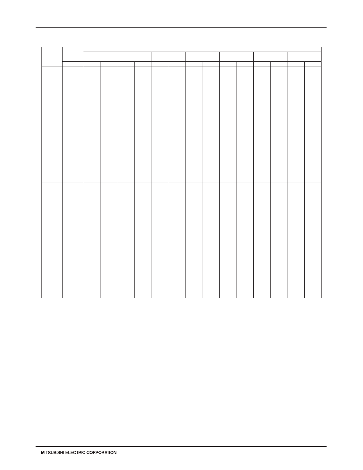
PURY-HP-T(S)KMU,-Y(S)KMU (September 2014)
H2i-R2-51
© 2014 Mitsubishi Electric US, Inc.
7. CAPACITY TABLES
7-4-3. Cooling Capacity with PURY-HP144TSKMU-A-H (cont.)
6. CAPACITY TABLES
DATA U10
60 23.0 82100 12700 85100 13600 90700 15400 94700 15500 96300 17100 102200 17300 109200 17600
32.0 82100 12900 85100 13800 90700 15600 94700 15700 96300 17200 102200 17500 109200 17800
41.0 82100 13000 85100 14000 90700 15800 94700 15900 96300 17400 102200 17700 109200 18000
50.0 82100 13200 85100 14100 90700 15900 94700 16100 96300 17600 102200 17900 109200 18100
54.0 82100 13300 85100 14200 90700 16000 94700 16200 96300 17700 102200 17900 109200 18200
57.0 82100 13400 85100 14300 90700 16100 94700 16200 96300 17700 102200 18000 109200 18300
61.0 82100 13500 85100 14400 90700 16200 94700 16300 96300 17800 102200 18100 109200 18400
64.0 82100 13500 85100 14400 90700 16200 94700 16400 96300 17900 102200 18100 108600 18700
68.0 82100 13600 85100 14500 90700 16300 94600 16500 96000 18200 101100 18800 107100 19500
70.0 82100 13600 85100 14600 90400 16600 94000 16900 95400 18500 100500 19200 106400 19800
73.0 81800 14000 84500 15100 89500 17200 93100 17500 94500 19100 99400 19700 105300 20400
77.0 80800 14800 83500 15900 88400 18100 92000 18400 93300 19900 98100 20500 103900 21100
81.0 79800 15700 82400 16800 87300 18900 90800 19200 92100 20700 96800 21300 102500 21900
84.0 79000 16300 81600 17500 86400 19600 89900 19800 91100 21300 95700 21900 101400 22400
88.0 78000 17200 80500 18400 85200 20400 88700 20600 89900 22100 94400 22600 100000 23200
90.0 77500 17600 80000 18800 84700 20800 88100 21000 89300 22500 93700 23000 99200 23600
91.0 77200 17800 79700 19100 84300 21100 87700 21300 89000 22700 93300 23200 98900 23800
95.0 76200 18700 78600 20000 83200 21900 86400 22100 87800 23500 92000 24000 97400 24500
99.0 75200 19500 77600 20900 82100 22700 85400 22900 86600 24200 90700 24700 96000 25200
102.0 74400 20200 76700 21500 81200 23400 84500 23500 85600 24800 89600 25300 94900 25800
104.0 73900 20600 76200 22000 80600 23800 83900 24000 85000 25200 89000 25700 94200 26200
108.0 72900 21500 75100 22900 79500 24700 82700 24800 83800 26000 87600 26500 92800 26900
110.0 70900 21200 73100 22600 77400 24400 80600 24500 81700 25700 85500 26200 90600 26600
115.0 56200 16100 58400 17600 62700 19300 65900 19400 67000 20700 70800 21100 75900 21500
50 23.0 68400 10900 71000 11600 75600 13200 78900 13300 80300 14600 85200 14800 91100 15100
32.0 68400 11000 71000 11800 75600 13300 78900 13500 80300 14800 85200 15000 91000 15200
41.0 68400 11200 71000 12000 75600 13500 78900 13600 80300 14900 85200 15200 91000 15400
50.0 68400 11400 71000 12100 75600 13700 78900 13800 80300 15100 85200 15300 91100 15600
54.0 68400 11400 71000 12200 75600 13800 78900 13900 80300 15200 85200 15400 91100 15600
57.0 68400 11500 71000 12300 75600 13800 78900 13900 80300 15200 85200 15400 91100 15700
61.0 68400 11500 71000 12300 75600 13900 78900 14000 80300 15300 85200 15500 91100 15700
64.0 68400 11600 71000 12400 75600 13900 78900 14000 80300 15300 85200 15600 90500 16100
68.0 68400 11700 71000 12500 75600 14000 78900 14100 80000 15600 84300 16100 89300 16700
70.0 68400 11700 71000 12500 75400 14200 78400 14500 79500 15900 83800 16400 88700 17000
73.0 68200 12000 70500 12900 74600 14800 77600 15000 78800 16400 82900 16900 87800 17500
77.0 67300 12700 69600 13700 73700 15500 76700 15700 77700 17100 81800 17600 86600 18100
81.0 66500 13400 68700 14400 72700 16200 75700 16500 76700 17800 80700 18200 85400 18800
84.0 65900 14000 68000 15000 72000 16800 74900 17000 76000 18300 79800 18700 84500 19300
88.0 65000 14700 67100 15800 71100 17500 73900 17700 75000 18900 78700 19400 83300 19900
90.0 64600 15100 66700 16200 70600 17900 73400 18100 74500 19300 78100 19700 82700 20200
91.0 64400 15300 66400 16400 70300 18100 73100 18200 74200 19500 77800 19900 82400 20400
95.0 63500 16000 65500 17100 69400 18800 72000 19000 73200 20100 76700 20600 81200 21000
99.0 62700 16700 64700 17900 68400 19500 71200 19700 72200 20800 75600 21200 80000 21600
102.0 62100 17300 64000 18500 67700 20100 70500 20200 71400 21300 74700 21700 79100 22100
104.0 61600 17700 63500 18900 67200 20400 70000 20600 70900 21600 74200 22000 78500 22400
108.0 60800 18400 62600 19600 66300 21200 69000 21300 69900 22300 73000 22700 77300 23100
110.0 59100 18200 60900 19400 64500 20900 67200 21000 68100 22100 71300 22400 75500 22800
115.0 46900 13800 48700 15100 52300 16600 55000 16700 55900 17700 59000 18100 63300 18500
PURY-HP144TSKMU-A-H
TC:Total Capacity(BTU), PI:Power Input(BTU)
Combination Outdoor Indoor air temp.
(%) air temp. 71°F D.B. 73°F D.B. 77°F D.B. 80°F D.B. 82°F D.B. 86°F D.B. 90°F D.B.
59°F W.B. 61°F W.B. 64°F W.B. 67°F W.B. 69°F W.B. 72°F W.B. 75°F W.B.
°F D.B. T C PI TC PI TC PI TC PI TC PI TC PI TC PI
kcal/h=kW x 860 , BTU/h = kW x 3,412
Page 52

H2i-R2-52
PURY-HP-T(S)KMU,-Y(S)KMU (September 2014)
© 2014 Mitsubishi Electric US, Inc.
7. CAPACITY TABLES
7-4-4. Cooling Capacity with PURY-HP192TSKMU-A-H
6. CAPACITY TABLES
DATA U10
H2i R2
PURY-HP192TSKMU-A-H TC:Total Capacity(BTU), PI:Power Input(BTU)
Combination Outdoor Indoor air temp.
(%) air temp. 71°F D.B. 73°F D.B. 77°F D.B. 80°F D.B. 82°F D.B. 86°F D.B. 90°F D.B.
59°F W.B. 61°F W.B. 64°F W.B. 67°F W.B. 69°F W.B. 72°F W.B. 75°F W.B.
°F D.B. TC PI TC PI TC PI TC PI TC PI TC PI TC PI
150 23.0 200500 31300 207900 33600 221600 38000 231300 38300 235300 42200 249700 42800 266800 43500
32.0 200500 31800 207900 34000 221600 38500 231300 38800 235300 42600 249700 43200 266700 43900
41.0 200500 32300 207900 34500 221600 38900 231300 39300 235300 43100 249700 43700 266700 44400
50.0 200500 32700 207900 35000 221600 39400 231300 39700 235300 43500 249700 44200 266800 44800
54.0 200500 32900 207900 35200 221600 39600 231300 39900 235300 43700 249700 44400 266800 45000
57.0 200500 33100 207900 35300 221600 39800 231300 40100 235300 43900 249700 44500 266800 45200
61.0 200500 33300 207900 35500 221600 40000 231300 40300 235300 44100 249700 44700 266800 45400
64.0 200500 33400 207900 35700 221600 40200 231300 40500 235300 44200 249700 44900 265200 46300
68.0 200500 33600 207900 35900 221600 40400 231100 40800 234500 44900 247000 46400 261700 48100
70.0 200500 33700 207900 36000 220800 41000 229700 41800 233000 45900 245400 47400 260000 49000
73.0 199700 34500 206500 37200 218700 42600 227500 43400 230700 47300 242900 48800 257300 50400
77.0 197300 36600 203900 39400 215900 44700 224600 45400 227800 49300 239600 50700 253800 52300
81.0 194800 38700 201300 41600 213100 46800 221700 47400 224800 51200 236300 52600 250300 54100
84.0 192900 40300 199200 43300 211000 48400 219500 49000 222600 52700 233800 54000 247600 55500
88.0 190500 42400 196600 45500 208200 50500 216500 51000 219600 54600 230500 55900 244100 57300
90.0 189300 43500 195300 46600 206800 51500 215100 52000 218100 55600 228900 56900 242400 58200
91.0 188600 44100 194600 47200 206000 52100 214300 52600 217300 56100 228000 57400 241400 58700
95.0 186200 46200 192000 49400 203200 54200 211000 54600 214400 58000 224700 59300 238000 60600
99.0 183700 48300 189400 51600 200400 56200 208500 56600 211400 59900 221400 61100 234500 62400
102.0 181800 49900 187400 53300 198300 57800 206400 58200 209100 61400 218900 62600 231800 63800
104.0 180600 50900 186100 54400 196900 58900 205000 59200 207700 62400 217300 63500 230100 64700
108.0 178200 53000 183500 56600 194100 61000 202100 61300 204700 64300 214000 65400 226600 66500
110.0 173200 52400 178500 55900 189000 60300 196900 60600 199600 63600 208800 64700 221300 65800
115.0 137300 39900 142600 43400 153200 47800 161100 48100 163700 51100 172900 52100 185400 53200
140 23.0 197600 31300 204900 33500 218400 37900 228000 38300 231900 42100 246100 42700 262900 43400
32.0 197600 31800 204900 34000 218400 38400 228000 38700 231900 42600 246100 43200 262900 43900
41.0 197600 32200 204900 34500 218400 38900 228000 39200 231900 43000 246100 43700 262900 44300
50.0 197600 32700 204900 34900 218400 39400 228000 39700 231900 43500 246100 44100 262900 44800
54.0 197600 32900 204900 35100 218400 39600 228000 39900 231900 43700 246100 44300 262900 45000
57.0 197600 33000 204900 35300 218400 39700 228000 40100 231900 43800 246100 44500 262900 45100
61.0 197600 33200 204900 35500 218400 40000 228000 40300 231900 44000 246100 44700 262900 45300
64.0 197600 33400 204900 35700 218400 40100 228000 40400 231900 44200 246100 44800 261400 46200
68.0 197600 33600 204900 35900 218400 40300 227800 40700 231100 44800 243500 46400 257900 48100
70.0 197600 33700 204900 36000 217700 40900 226400 41700 229700 45800 241900 47300 256200 49000
73.0 196900 34500 203500 37200 215500 42600 224200 43300 227400 47300 239400 48800 253600 50400
77.0 194400 36600 200900 39400 212800 44600 221400 45300 224500 49200 236200 50600 250100 52200
81.0 192000 38700 198400 41600 210000 46700 218500 47400 221600 51100 232900 52500 246700 54000
84.0 190200 40300 196400 43300 207900 48300 216300 48900 219400 52600 230400 54000 244100 55400
88.0 187800 42400 193800 45500 205200 50400 213400 51000 216500 54500 227200 55900 240600 57300
90.0 186600 43400 192500 46500 203800 51400 212000 52000 215000 55500 225600 56800 238900 58200
91.0 185900 44000 191800 47100 203100 52000 211200 52500 214200 56000 224700 57300 238000 58700
95.0 183500 46100 189300 49300 200300 54100 208000 54600 211300 57900 221500 59200 234600 60500
99.0 181100 48200 186700 51500 197600 56200 205500 56600 208400 59900 218300 61100 231100 62300
102.0 179200 49800 184700 53200 195400 57800 203400 58200 206100 61400 215800 62500 228500 63700
104.0 178000 50900 183400 54300 194100 58800 202100 59200 204700 62300 214200 63500 226800 64600
108.0 175600 53000 180900 56500 191300 60900 199200 61200 201800 64200 210900 65300 223300 66500
110.0 170700 52300 175900 55900 186300 60200 194100 60500 196700 63500 205800 64600 218100 65700
115.0 135400 39800 140600 43400 151000 47700 158800 48000 161400 51000 170400 52100 182700 53200
130 23.0 194400 31300 201500 33500 214800 37900 224200 38200 228100 42100 242000 42700 258600 43400
32.0 194400 31700 201500 33900 214800 38400 224200 38700 228100 42500 242000 43100 258600 43800
41.0 194400 32200 201500 34400 214800 38800 224200 39200 228100 43000 242000 43600 258600 44300
50.0 194400 32600 201500 34900 214800 39300 224200 39600 228100 43400 242000 44000 258600 44700
54.0 194400 32800 201500 35100 214800 39500 224200 39800 228100 43600 242000 44200 258600 44900
57.0 194400 33000 201500 35200 214800 39700 224200 40000 228100 43800 242000 44400 258600 45100
61.0 194400 33200 201500 35400 214800 39900 224200 40200 228100 43900 242000 44600 258600 45300
64.0 194400 33300 201500 35600 214800 40100 224200 40400 228100 44100 242000 44700 257100 46200
68.0 194400 33500 201500 35800 214800 40300 224000 40700 227300 44800 239500 46300 253700 48000
70.0 194400 33700 201500 35900 214100 40900 222600 41700 225900 45700 237900 47200 252000 48900
73.0 193600 34400 200200 37100 212000 42500 220500 43200 223700 47200 235500 48700 249400 50300
77.0 191300 36500 197600 39300 209300 44600 217700 45300 220800 49100 232300 50600 246000 52100
81.0 188900 38600 195100 41500 206600 46600 214900 47300 218000 51100 229100 52400 242700 53900
84.0 187100 40200 193200 43200 204500 48200 212800 48900 215800 52500 226700 53900 240100 55400
88.0 184700 42300 190600 45400 201800 50300 209900 50900 212900 54500 223500 55800 236700 57200
90.0 183500 43400 189400 46500 200500 51400 208500 51900 211500 55400 221900 56700 235000 58100
91.0 182900 43900 188700 47100 199700 51900 207700 52400 210700 55900 221000 57200 234100 58600
95.0 180500 46000 186200 49300 197000 54000 204600 54500 207800 57900 217900 59100 230700 60400
99.0 178100 48100 183600 51400 194300 56100 202200 56500 205000 59800 214700 61000 227300 62200
102.0 176300 49800 181700 53100 192200 57700 200100 58100 202800 61300 212200 62400 224700 63600
104.0 175100 50800 180400 54200 190900 58700 198700 59100 201300 62200 210700 63400 223000 64500
108.0 172700 52900 177900 56400 188200 60800 195900 61100 198500 64100 207500 65200 219700 66400
110.0 167900 52200 173000 55800 183300 60100 190900 60400 193500 63400 202400 64500 214500 65600
115.0 133100 39800 138300 43300 148500 47700 156200 47900 158700 50900 167600 52000 179700 53100
kcal/h=kW x 860 , BTU/h = kW x 3,412
Page 53
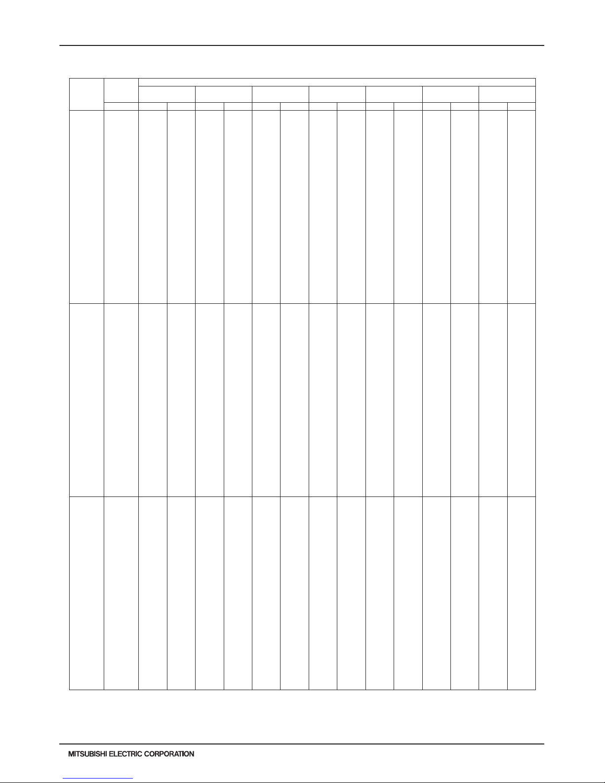
PURY-HP-T(S)KMU,-Y(S)KMU (September 2014)
H2i-R2-53
© 2014 Mitsubishi Electric US, Inc.
7. CAPACITY TABLES
7-4-4. Cooling Capacity with PURY-HP192TSKMU-A-H (cont.)
6. CAPACITY TABLES
DATA U10
120 23.0 190800 31200 197800 33400 210900 37800 220100 38100 223900 42000 237600 42600 253800 43300
32.0 190800 31700 197800 33900 2109 00 38300 220100 386 00 223900 42400 237600 43000 253800 43700
41.0 190800 32100 197800 34300 2109 00 38800 220100 391 00 223900 42900 237600 43500 253800 44200
50.0 190800 32600 197800 34800 2109 00 39200 220100 396 00 223900 43300 237600 44000 253800 44600
54.0 190800 32800 197800 35000 2109 00 39500 220100 398 00 223900 43500 237600 44200 253800 44800
57.0 190800 32900 197800 35200 2109 00 39600 220100 399 00 223900 43700 237600 44300 253800 45000
61.0 190800 33100 197800 35400 2109 00 39800 220100 401 00 223900 43900 237600 44500 253800 45200
64.0 190800 33300 197800 35500 2109 00 40000 220100 403 00 223900 44000 237600 44700 252300 46100
68.0 190800 33500 197800 35700 2109 00 40200 219900 406 00 223100 44700 235100 46200 249000 47900
70.0 190800 33600 197800 35800 2101 00 40800 218500 416 00 221700 45600 233500 47100 247400 48800
73.0 190000 34300 196500 37100 2081 00 42400 216400 432 00 219600 47100 231100 48600 244800 50200
77.0 187700 36400 194000 39200 2054 00 44500 213700 452 00 216700 49000 228000 50500 241500 52000
81.0 185400 38500 191500 41400 2028 00 46600 211000 472 00 213900 51000 224900 52300 238200 53800
84.0 183600 40100 189600 43100 2007 00 48200 208800 488 00 211800 52400 222500 53800 235600 55200
88.0 181300 42200 187100 45300 1981 00 50200 206000 508 00 209000 54300 219400 55700 232300 57100
90.0 180100 43300 185900 46400 1968 00 51300 204600 518 00 207600 55300 217800 56600 230700 58000
91.0 179500 43900 185200 47000 1960 00 51800 203900 523 00 206800 55800 216900 57100 229700 58500
95.0 177100 45900 182700 49200 1934 00 53900 200800 544 00 204000 57700 213800 59000 226400 60300
99.0 174800 48000 180200 51300 1907 00 56000 198400 564 00 201200 59700 210700 60900 223100 62100
102.0 173000 49700 178300 53000 188700 57600 196400 58000 199000 61100 208300 62300 220600 63500
104.0 171900 50700 177100 54100 187400 58600 195100 59000 197600 62100 206800 63200 218900 64400
108.0 169500 52800 174600 56300 184700 60700 192300 61000 194800 64000 203600 65100 215600 66200
110.0 164800 52100 169800 55700 179900 60000 187400 60300 189900 63300 198600 64400 210500 65500
115.0 130700 39700 135700 43200 145700 47600 153300 47800 155800 50800 164500 51900 176400 53000
110 23.0 186800 31100 193700 33300 206500 37700 215500 38000 219300 41900 232600 42500 248600 43200
32.0 186900 31600 193700 33800 2065 00 38200 215500 385 00 219300 42300 232600 42900 248600 43600
41.0 186900 32000 193700 34300 2065 00 38700 215500 390 00 219300 42800 232600 43400 248600 44100
50.0 186900 32500 193700 34700 2065 00 39100 215500 395 00 219300 43200 232600 43800 248600 44500
54.0 186900 32700 193700 34900 2065 00 39400 215500 397 00 219300 43400 232600 44000 248600 44700
57.0 186900 32800 193700 35100 2065 00 39500 215500 398 00 219300 43600 232600 44200 248600 44900
61.0 186900 33100 193700 35300 2065 00 39700 215500 400 00 219300 43800 232600 44400 248600 45100
64.0 186800 33200 193700 35500 2065 00 39900 215500 402 00 219300 43900 232600 44600 247100 46000
68.0 186800 33400 193700 35700 2065 00 40100 215300 405 00 218500 44600 230200 46100 243800 47800
70.0 186800 33500 193700 35800 2058 00 40700 214000 415 00 217100 45500 228700 47000 242200 48700
73.0 186100 34300 192400 37000 2038 00 42300 211900 431 00 215000 47000 226300 48500 239700 50100
77.0 183800 36300 190000 39200 2012 00 44400 209300 451 00 212300 48900 223300 50400 236500 51900
81.0 181500 38400 187500 41300 1986 00 46400 206600 471 00 209500 50800 220200 52200 233200 53700
84.0 179800 40000 185700 43000 1966 00 48000 204500 487 00 207400 52300 217900 53700 230700 55100
88.0 177500 42100 183200 45200 1940 00 50100 201800 507 00 204600 54200 214800 55500 227500 56900
90.0 176400 43200 182000 46300 1927 00 51100 200400 517 00 203300 55200 213300 56500 225900 57800
91.0 175700 43700 181400 46900 1920 00 51700 199600 522 00 202500 55700 212400 57000 225000 58300
95.0 173500 45800 178900 49000 1894 00 53800 196600 542 00 199800 57600 209400 58800 221700 60100
99.0 171200 47900 176500 51200 1868 00 55800 194300 563 00 197000 59500 206300 60700 218500 62000
102.0 169400 49500 174600 52900 184800 57400 192300 57800 194900 61000 204000 62200 216000 63400
104.0 168300 50600 173400 54000 183500 58500 191000 58800 193500 62000 202500 63100 214400 64300
108.0 166000 52700 171000 56200 180900 60500 188300 60800 190800 63900 199400 65000 211100 66100
110.0 161400 52000 166300 55600 176100 59900 183500 60200 186000 63100 194500 64200 206200 65300
115.0 128000 39600 132900 43100 142700 47400 150100 47700 152500 50700 161100 51800 172700 52900
100 23.0 182500 31000 189200 33200 201700 37600 210500 37900 214200 41800 227300 42400 242800 43100
32.0 182500 31500 189200 33700 2017 00 38100 210500 384 00 214200 42200 227300 42800 242800 43500
41.0 182500 31900 189200 34200 2017 00 38600 210500 389 00 214200 42700 227300 43300 242800 44000
50.0 182500 32400 189200 34600 2017 00 39000 210500 394 00 214200 43100 227300 43700 242800 44400
54.0 182500 32600 189200 34800 2017 00 39300 210500 396 00 214200 43300 227300 43900 242800 44600
57.0 182500 32800 189200 35000 2017 00 39400 210500 397 00 214200 43400 227300 44100 242800 44800
61.0 182500 33000 189200 35200 2017 00 39600 210500 399 00 214200 43600 227300 44300 242800 45000
64.0 182500 33100 189200 35400 2017 00 39800 210500 401 00 214200 43800 227300 44400 241400 45900
68.0 182500 33300 189200 35600 2017 00 40000 210300 404 00 213400 44500 224900 46000 238200 47700
70.0 182500 33400 189200 35700 2010 00 40600 209000 414 00 212100 45400 223400 46900 236600 48600
73.0 181800 34200 187900 36900 1991 00 42200 207000 429 00 210000 46900 221100 48300 234200 50000
77.0 179600 36200 185600 39000 1965 00 44300 204400 450 00 207300 48800 218100 50200 231000 51800
81.0 177300 38300 183200 41200 1940 00 46300 201800 470 00 204700 50700 215100 52100 227800 53600
84.0 175600 39900 181400 42900 1920 00 47900 199800 485 00 202600 52200 212800 53500 225400 55000
88.0 173400 42000 179000 45100 1895 00 50000 197100 505 00 199900 54100 209800 55400 222200 56800
90.0 172300 43100 177800 46200 1882 00 51000 195800 515 00 198600 55000 208400 56300 220600 57700
91.0 171700 43600 177200 46700 1875 00 51600 195000 521 00 197800 55500 207500 56800 219800 58200
95.0 169500 45700 174800 48900 1850 00 53600 192000 541 00 195100 57500 204600 58700 216600 60000
99.0 167200 47800 172400 51100 1825 00 55700 189800 561 00 192500 59400 201600 60500 213400 61800
102.0 165500 49400 170600 52800 180500 57300 187900 57700 190400 60800 199300 62000 211000 63200
104.0 164400 50400 169400 53800 179200 58300 186600 58700 189000 61800 197800 62900 209400 64100
108.0 162200 52500 167000 56000 176700 60400 183900 60700 186400 63700 194800 64800 206200 65900
110.0 157700 51900 162500 55400 172100 59700 179300 60000 181700 63000 190000 64100 201400 65100
115.0 125000 39500 129800 43000 139400 47300 146600 47600 149000 50600 157400 51600 168700 52700
PURY-HP192TSKMU-A-H
TC:Total Capacity(BTU), PI:Power Input(BTU)
Combination Outdoor Indoor air temp.
(%) air temp. 71°F D.B. 73°F D.B. 77°F D.B. 80°F D.B. 82°F D.B. 86°F D.B. 90°F D.B.
59°F W.B. 61°F W.B. 64°F W.B. 67°F W.B. 69°F W.B. 72°F W.B. 75°F W.B.
°F D.B. T C PI TC PI TC PI TC PI TC PI TC PI TC PI
kcal/h=kW x 860 , BTU/h = kW x 3,412
Page 54
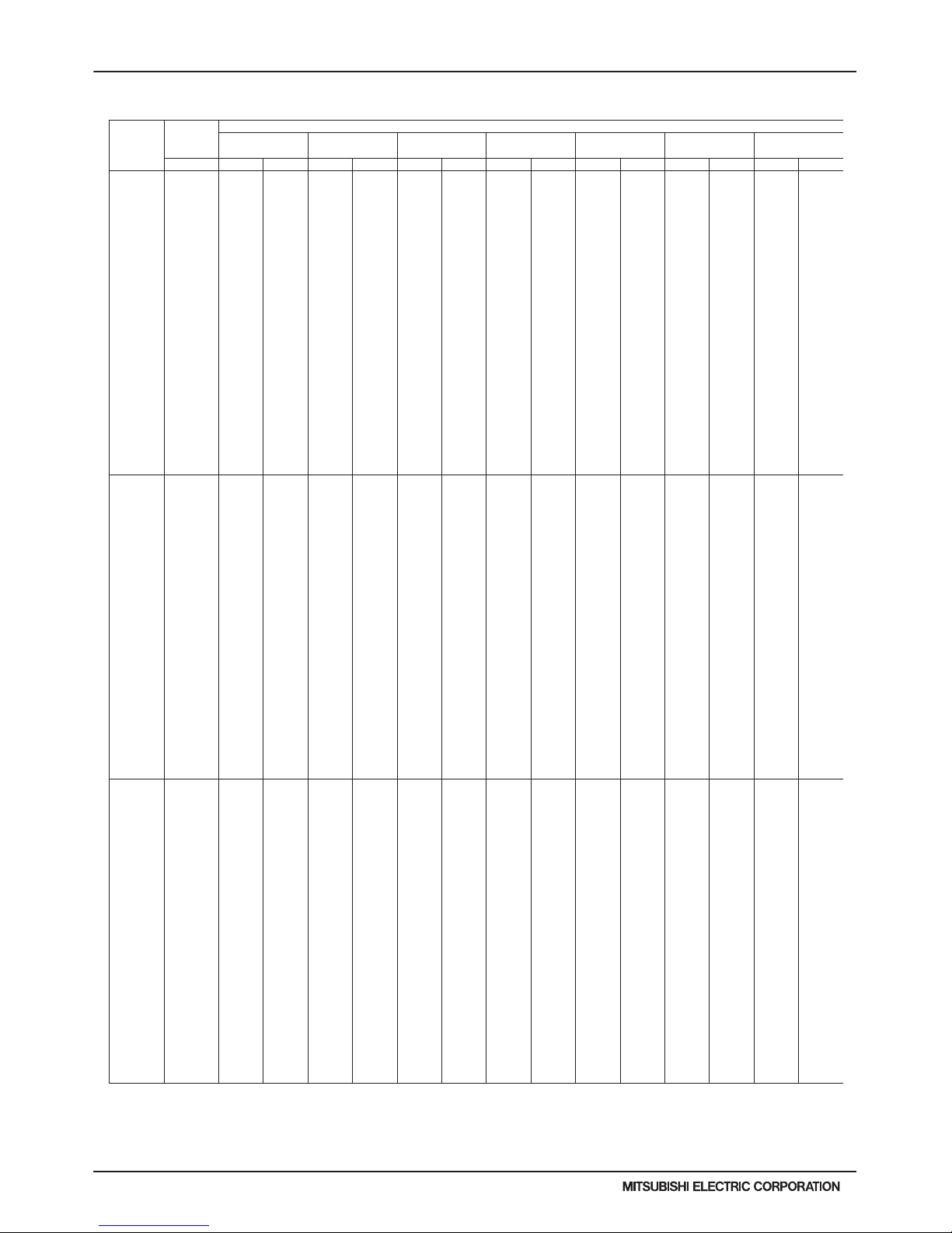
H2i-R2-54
PURY-HP-T(S)KMU,-Y(S)KMU (September 2014)
© 2014 Mitsubishi Electric US, Inc.
7. CAPACITY TABLES
7-4-4. Cooling Capacity with PURY-HP192TSKMU-A-H (cont.)
6. CAPACITY TABLES
DATA U10
H2i R2
90 23.0 164300 27000 170300 28900 181600 32700 189500 33000 192800 36300 204600 36800 218600 37500
32.0 164300 27400 170300 29300 181600 33100 189500 33400 192800 36700 204600 37200 218600 37800
41.0 164300 27800 170300 29700 181600 33500 189500 33800 192800 37100 204600 37600 218600 38200
50.0 164300 28200 170300 30100 181600 33900 189500 34200 192800 37500 204600 38000 218600 38600
54.0 164300 28300 170300 30300 181600 34100 189500 34400 192800 37600 204600 38200 218600 38800
57.0 164300 28500 170300 30400 181600 34300 189500 34500 192800 37800 204600 38300 218600 38900
61.0 164300 28700 170300 30600 181600 34400 189500 34700 192800 37900 204600 38500 218600 39100
64.0 164300 28800 170300 30700 181600 34600 189500 34800 192800 38100 204600 38600 217300 39900
68.0 164300 29000 170300 30900 181600 34800 189300 35100 192100 38700 202400 40000 214400 41400
70.0 164300 29100 170300 31000 180900 35300 188200 36000 190900 39500 201100 40800 213000 42200
73.0 163600 29700 169200 32100 179200 36700 186400 37300 189100 40800 199000 42000 210800 43400
77.0 161600 31500 167000 33900 176900 38500 184000 39100 186600 42400 196300 43700 207900 45000
81.0 159600 33300 164900 35800 174600 40300 181700 40800 184200 44100 193600 45300 205100 46600
84.0 158100 34700 163300 37300 172800 41700 179800 42200 182400 45400 191600 46500 202900 47800
88.0 156100 36500 161100 39200 170600 43400 177400 43900 179900 47000 188900 48100 200000 49400
90.0 155100 37400 160100 40100 169400 44300 176200 44800 178700 47800 187500 49000 198600 50100
91.0 154500 37900 159500 40600 168800 44800 175600 45300 178100 48300 186800 49400 197800 50600
95.0 152500 39700 157300 42500 166500 46600 172900 47000 175700 49900 184100 51000 195000 52100
99.0 150500 41600 155200 44400 164200 48400 170900 48800 173200 51600 181400 52600 192100 53700
102.0 149000 43000 153600 45900 162500 49800 169100 50100 171400 52900 179400 53900 189900 54900
104.0 148000 43900 152500 46800 161300 50700 168000 51000 170200 53700 178000 54700 188500 55700
108.0 146000 45700 150300 48700 159000 52500 165600 52700 167700 55400 175400 56300 185700 57300
110.0 141900 45100 146200 48200 154900 51900 161400 52200 163500 54700 171000 55700 181300 56600
115.0 112500 34300 116800 37400 125500 41100 132000 41400 134100 44000 141700 44900 151900 45800
80 23.0 146100 23300 151400 24900 161400 28200 168500 28500 171400 31300 181900 31800 194300 32300
32.0 146100 23600 151400 25300 161400 28600 168500 28800 171400 31700 181900 32100 194300 32600
41.0 146100 24000 151400 25600 161400 28900 168500 29200 171400 32000 181900 32500 194300 33000
50.0 146100 24300 151400 26000 161400 29300 168500 29500 171400 32300 181900 32800 194300 33300
54.0 146100 24500 151400 26100 161400 29400 168500 29700 171400 32500 181900 32900 194300 33500
57.0 146100 24600 151400 26200 161400 29600 168500 29800 171400 32600 181900 33100 194300 33600
61.0 146100 24700 151400 26400 161400 29700 168500 29900 171400 32700 181900 33200 194300 33700
64.0 146100 24800 151400 26500 161400 29800 168500 30100 171400 32800 181900 33300 193200 34400
68.0 146100 25000 151400 26700 161400 30000 168300 30300 170800 33300 179900 34500 190600 35700
70.0 146100 25100 151400 26700 160900 30400 167300 31000 169700 34100 178800 35200 189300 36400
73.0 145500 25600 150400 27700 159300 31600 165700 32200 168100 35200 176900 36300 187400 37500
77.0 143700 27200 148500 29300 157300 33200 163600 33700 165900 36600 174500 37700 184900 38800
81.0 141900 28700 146600 30900 155200 34700 161500 35200 163800 38000 172100 39100 182300 40200
84.0 140500 30000 145100 32200 153700 35900 159900 36400 162100 39100 170300 40100 180400 41200
88.0 138800 31500 143200 33800 151600 37500 157700 37900 160000 40600 167900 41500 177800 42600
90.0 137900 32300 142300 34600 150600 38300 156700 38700 158900 41300 166700 42200 176600 43300
91.0 137400 32700 141800 35100 150100 38700 156100 39100 158300 41700 166100 42600 175900 43600
95.0 135600 34300 139900 36700 148000 40200 153700 40600 156200 43100 163700 44000 173300 45000
99.0 133800 35800 138000 38300 146000 41800 151900 42100 154000 44500 161300 45400 170800 46300
102.0 132400 37100 136500 39600 144400 43000 150400 43200 152300 45600 159500 46500 168800 47400
104.0 131600 37800 135600 40400 143400 43700 149300 44000 151300 46300 158300 47200 167600 48100
108.0 129800 39400 133700 42000 141400 45300 147200 45500 149100 47800 155900 48600 165000 49400
110.0 126200 38900 130000 41600 137700 44800 143500 45000 145400 47200 152100 48000 161200 48900
115.0 100000 29600 103900 32200 111600 35500 117300 35700 119200 37900 125900 38700 135000 39500
70 23.0 127800 19900 132500 21300 141200 24200 147400 24400 150000 26800 159100 27200 170000 27700
32.0 127800 20200 132500 21600 141200 24500 147400 24700 150000 27100 159100 27500 170000 27900
41.0 127800 20500 132500 21900 141200 24800 147400 25000 150000 27400 159100 27800 170000 28200
50.0 127800 20800 132500 22200 141200 25100 147400 25300 150000 27700 159100 28100 170000 28500
54.0 127800 20900 132500 22400 141200 25200 147400 25400 150000 27800 159100 28200 170000 28600
57.0 127800 21000 132500 22500 141200 25300 147400 25500 150000 27900 159100 28300 170000 28700
61.0 127800 21200 132500 22600 141200 25400 147400 25600 150000 28000 159100 28400 170000 28900
64.0 127800 21300 132500 22700 141200 25500 147400 25700 150000 28100 159100 28500 169000 29400
68.0 127800 21400 132500 22800 141200 25700 147300 25900 149500 28500 157500 29500 166800 30600
70.0 127800 21500 132500 22900 140800 26100 146400 26600 148500 29200 156400 30100 165700 31200
73.0 127300 21900 131600 23700 139400 27100 145000 27600 147100 30100 154800 31000 164000 32100
77.0 125700 23300 129900 25100 137600 28400 143200 28900 145200 31300 152700 32200 161800 33200
81.0 124200 24600 128300 26500 135800 29700 141300 30100 143300 32500 150600 33400 159500 34400
84.0 123000 25600 127000 27500 134500 30800 139900 31100 141900 33500 149000 34400 157800 35300
88.0 121400 27000 125300 28900 132700 32100 138000 32400 140000 34700 146900 35600 155600 36400
90.0 120600 27600 124500 29600 131800 32700 137100 33100 139000 35300 145900 36200 154500 37000
91.0 120200 28000 124100 30000 131300 33100 136600 33400 138500 35700 145300 36500 153900 37300
95.0 118700 29300 122400 31400 129500 34400 134500 34700 136600 36900 143200 37700 151700 38500
99.0 117100 30700 120700 32800 127800 35800 132900 36000 134800 38100 141100 38900 149500 39700
102.0 115900 31700 119400 33900 126400 36800 131600 37000 133300 39000 139500 39800 147700 40600
104.0 115100 32400 118600 34600 125500 37400 130700 37700 132400 39700 138500 40400 146600 41100
108.0 113600 33700 117000 36000 123700 38800 128800 38900 130500 40900 136400 41600 144400 42300
110.0 110400 33300 113800 35600 120500 38300 125500 38500 127200 40400 133100 41100 141000 41800
115.0 87500 25300 90900 27600 97600 30400 102700 30600 104300 32500 110200 33200 118200 33900
PURY-HP192TSKMU-A-H TC:Total Capacity(BTU), PI:Power Input(BTU)
Combination Outdoor Indoor air temp.
(%) air temp. 71°F D.B. 73°F D.B. 77°F D.B. 80°F D.B. 82°F D.B. 86°F D.B. 90°F D.B.
59°F W.B. 61°F W.B. 64°F W.B. 67°F W.B. 69°F W.B. 72°F W.B. 75°F W.B.
°F D.B. TC PI TC PI TC PI TC PI TC PI TC PI TC PI
kcal/h=kW x 860 , BTU/h = kW x 3,412
Page 55

PURY-HP-T(S)KMU,-Y(S)KMU (September 2014)
H2i-R2-55
© 2014 Mitsubishi Electric US, Inc.
7. CAPACITY TABLES
7-4-4. Cooling Capacity with PURY-HP192TSKMU-A-H (cont.)
6. CAPACITY TABLES
DATA U10
60 23.0 109500 16900 113600 18100 121100 20500 126400 20700 128500 22800 136400 23100 145700 23500
32.0 109500 17200 113600 18400 121100 20800 126400 20900 128500 23000 136400 23400 145700 23700
41.0 109500 17400 113600 18600 121100 21000 126400 21200 128500 23300 136400 23600 145700 24000
50.0 109500 17700 113600 18900 121100 21300 126400 21500 128500 23500 136400 23800 145700 24200
54.0 109500 17800 113600 19000 121100 21400 126400 21600 128500 23600 136400 23900 145700 24300
57.0 109500 17900 113600 19100 121100 21500 126400 21700 128500 23700 136400 24000 145700 24400
61.0 109500 18000 113600 19200 121100 21600 126400 21800 128500 23800 136400 24100 145700 24500
64.0 109500 18100 113600 19300 121100 21700 126400 21900 128500 23900 136400 24200 144900 25000
68.0 109500 18200 113600 19400 121100 21800 126200 22000 128100 24200 135000 25100 143000 26000
70.0 109500 18200 113600 19400 120600 22100 125500 22600 127300 24800 134100 25600 142000 26500
73.0 109100 18600 112800 20100 119500 23000 124300 23400 126100 25600 132700 26400 140500 27200
77.0 107800 19800 111400 21300 117900 24100 122700 24500 124400 26600 130900 27400 138600 28200
81.0 106400 20900 109900 22500 116400 25300 121100 25600 122800 27600 129100 28400 136700 29200
84.0 105400 21800 108800 23400 115200 26100 119900 26500 121600 28400 127700 29200 135300 30000
88.0 104100 22900 107400 24600 113700 27200 118300 27500 120000 29500 125900 30200 133400 31000
90.0 103400 23500 106700 25200 113000 27800 117500 28100 119200 30000 125000 30700 132400 31400
91.0 103000 23800 106300 25500 112500 28100 117000 28400 118700 30300 124600 31000 131900 31700
95.0 101700 24900 104900 26700 111000 29200 115300 29500 117100 31300 122800 32000 130000 32700
99.0 100400 26100 103500 27900 109500 30400 113900 30600 115500 32400 121000 33000 128100 33700
102.0 99300 26900 102400 28800 108300 31200 112800 31400 114300 33200 119600 33800 126600 34400
104.0 98700 27500 101700 29400 107600 31800 112000 32000 113500 33700 118700 34300 125700 34900
108.0 97300 28600 100200 30500 106000 32900 110400 33100 111800 34700 116900 35300 123800 35900
110.0 94600 28300 97500 30200 103300 32600 107600 32700 109000 34300 114000 34900 120900 35500
115.0 75000 21500 77900 23400 83700 25800 88000 25900 89400 27600 94400 28200 101300 28700
50 23.0 91300 14300 94600 15300 100900 17300 105300 17400 107100 19200 113600 19500 121400 19800
32.0 91300 14500 94600 15500 100900 17500 105300 17700 107100 19400 113600 19700 121400 20000
41.0 91300 14700 94600 15700 100900 17700 105300 17900 107100 19600 113600 19900 121400 20200
50.0 91300 14900 94600 15900 100900 17900 105300 18100 107100 19800 113600 20100 121400 20400
54.0 91300 15000 94600 16000 100900 18000 105300 18200 107100 19900 113600 20200 121400 20500
57.0 91300 15100 94600 16100 100900 18100 105300 18300 107100 20000 113600 20300 121400 20600
61.0 91300 15200 94600 16200 100900 18200 105300 18400 107100 20100 113600 20400 121400 20700
64.0 91300 15200 94600 16300 100900 18300 105300 18400 107100 20100 113600 20400 120700 21100
68.0 91300 15300 94600 16300 100900 18400 105200 18600 106700 20400 112400 21100 119100 21900
70.0 91300 15400 94600 16400 100500 18700 104500 19000 106100 20900 111700 21600 118300 22300
73.0 90900 15700 9 4000 17000 99500 19400 103500 19700 105000 2 1600 110500 22200 11 7100 23000
77.0 89800 16700 9 2800 18000 98300 20300 102200 20700 103700 2 2400 109100 23100 11 5500 23800
81.0 88700 17600 9 1600 18900 97000 21300 100900 21600 102300 2 3300 107600 23900 11 3900 24600
84.0 87800 18400 90700 19700 96000 22000 99900 22300 101300 24000 106400 24600 112700 25300
88.0 86700 19300 89500 20700 94800 23000 98600 23200 100000 24900 104900 25500 111100 26100
90.0 86200 19800 88900 21200 94100 23400 97900 23700 99300 25300 104200 25900 110300 26500
91.0 85800 20100 88600 21500 93800 23700 97500 23900 98900 25500 103800 26100 109900 26700
95.0 84700 21000 87400 22500 92500 24700 96100 24900 97600 26400 102300 27000 108300 27600
99.0 83600 22000 86200 23500 91200 25600 94900 25800 96200 27300 100800 27800 106700 28400
102.0 82800 22700 85300 24300 90300 26300 94000 26500 95200 28000 99600 28500 105500 29000
104.0 82200 23200 84700 24800 89600 26800 93300 27000 94500 28400 98900 28900 104700 29500
108.0 81100 24100 83500 25800 88400 27800 92000 27900 93200 29300 97400 29800 103100 30300
110.0 78800 23900 81200 25500 86000 27500 89600 27600 90800 29000 95000 29400 100700 29900
115.0 62500 18100 64900 19800 69700 21800 73300 21900 74500 23200 78700 23700 84400 24200
PURY-HP192TSKMU-A-H
TC:Total Capacity(BTU), PI:Power Input(BTU)
Combination Outdoor Indoor air temp.
(%) air temp. 71°F D.B. 73°F D.B. 77°F D.B. 80°F D.B. 82°F D.B. 86°F D.B. 90°F D.B.
59°F W.B. 61°F W.B. 64°F W.B. 67°F W.B. 69°F W.B. 72°F W.B. 75°F W.B.
°F D.B. T C PI TC PI TC PI TC PI TC PI TC PI TC PI
kcal/h=kW x 860 , BTU/h = kW x 3,412
Page 56

H2i-R2-56
PURY-HP-T(S)KMU,-Y(S)KMU (September 2014)
© 2014 Mitsubishi Electric US, Inc.
7. CAPACITY TABLES
7-4-5. Cooling Capacity with PURY-HP72YKMU-A
6. CAPACITY TABLES
DATA U10
H2i R2
PURY-HP72YKMU-A TC:Total Capacity(BTU), PI:Power Input(BTU)
Combination Outdoor Indoor air temp.
(%) air temp. 71°F D.B. 73°F D.B. 77°F D.B. 80°F D.B. 82°F D.B. 86°F D.B. 90°F D.B.
59°F W.B. 61°F W.B. 64°F W.B. 67°F W.B. 69°F W.B. 72°F W.B. 75°F W.B.
°F D.B. TC PI TC PI TC PI TC PI TC PI TC PI TC PI
150 23.0 74900 10200 77700 10900 82800 12300 86400 12400 87900 13700 93300 13900 99600 14100
32.0 74900 10300 77700 11000 82800 12500 86400 12600 87900 13800 93300 14000 99600 14300
41.0 74900 10500 77700 11200 82800 12600 86400 12700 87900 14000 93300 14200 99600 14400
50.0 74900 10600 77700 11300 82800 12800 86400 12900 87900 14100 93300 14300 99600 14600
54.0 74900 10700 77700 11400 82800 12900 86400 13000 87900 14200 93300 14400 99600 14600
57.0 74900 10700 77700 11500 82800 12900 86400 13000 87900 14200 93300 14400 99600 14700
61.0 74900 10800 77700 11500 82800 13000 86400 13100 87900 14300 93300 14500 99600 14700
64.0 74900 10900 77700 11600 82800 13000 86400 13100 87900 14400 93300 14600 99100 15000
68.0 74900 10900 77700 11700 82800 13100 86300 13200 87600 14600 92300 15100 97800 15600
70.0 74900 11000 77700 11700 82500 13300 85800 13600 87000 14900 91700 15400 97100 15900
73.0 74600 11200 77100 12100 81700 13800 85000 14100 86200 15400 90700 15800 96100 16400
77.0 73700 11900 76200 12800 80600 14500 83900 14700 85100 16000 89500 16500 94800 17000
81.0 72800 12600 75200 13500 79600 15200 82800 15400 84000 16600 88300 17100 93500 17600
84.0 72100 13100 74400 14100 78800 15700 82000 15900 83100 17100 87300 17500 92500 18000
88.0 71200 13800 73500 14800 77800 16400 80900 16600 82000 17700 86100 18200 91200 18600
90.0 70700 14100 73000 15100 77200 16700 80300 16900 81500 18000 85500 18500 90500 18900
91.0 70500 14300 72700 15300 77000 16900 80000 17100 81200 18200 85200 18600 90200 19100
95.0 69500 15000 71700 16000 75900 17600 78800 17700 80100 18800 83900 19200 88900 19700
99.0 68600 15700 70800 16700 74900 18300 77900 18400 79000 19500 82700 19800 87600 20200
102.0 67900 16200 70000 17300 74100 18800 77100 18900 78100 19900 81800 20300 86600 20700
104.0 67500 16500 69500 17600 73600 19100 76600 19200 77600 20200 81200 20600 85900 21000
108.0 66600 17200 68500 18400 72500 19800 75500 19900 76500 20900 79900 21200 84600 21600
110.0 64700 17000 66700 18200 70600 19600 73600 19700 74600 20600 78000 21000 82600 21300
115.0 51300 12900 53300 14100 57200 15500 60200 15600 61200 16600 64600 16900 69200 17300
140 23.0 73900 10100 76600 10900 81600 12300 85200 12400 86700 13600 92000 13800 98300 14100
32.0 73900 10300 76600 11000 81600 12400 8520 0 12500 8670 0 13800 92 000 14000 98 300 14200
41.0 73900 10400 76600 11200 81600 12600 8520 0 12700 8670 0 13900 92 000 14100 98 300 14400
50.0 73900 10600 76600 11300 81600 12700 8520 0 12800 8670 0 14100 92 000 14300 98 300 14500
54.0 73900 10600 76600 11400 81600 12800 8520 0 12900 8670 0 14100 92 000 14300 98 300 14600
57.0 73900 10700 76600 11400 81600 12900 8520 0 13000 8670 0 14200 92 000 14400 98 300 14600
61.0 73900 10800 76600 11500 81600 12900 8520 0 13000 8670 0 14200 92 000 14500 98 300 14700
64.0 73900 10800 76600 11500 81600 13000 8520 0 13100 8670 0 14300 92 000 14500 97 700 15000
68.0 73900 10900 76600 11600 81600 13100 8510 0 13200 8640 0 14500 91 000 15000 96 400 15600
70.0 73900 10900 76600 11600 81400 13300 8460 0 13500 8580 0 14800 90 400 15300 95 800 15900
73.0 73600 11200 76100 12000 80600 13800 8380 0 14000 8500 0 15300 89 500 15800 94 800 16300
77.0 72700 11800 75100 12700 79500 14400 8270 0 14700 8390 0 15900 88 300 16400 93 500 16900
81.0 71800 12500 74100 13500 78500 15100 8170 0 15300 8280 0 16500 87 100 17000 92 200 17500
84.0 71100 13000 73400 14000 77700 15600 8080 0 15800 8200 0 17000 86 100 17500 91 200 17900
88.0 70200 13700 72400 14700 76700 16300 7980 0 16500 8090 0 17700 84 900 18100 89 900 18500
90.0 69700 14100 72000 15100 76200 16700 7920 0 16800 8040 0 18000 84 300 18400 89 300 18800
91.0 69500 14200 71700 15300 75900 16800 7890 0 17000 8010 0 18100 84 000 18500 88 900 19000
95.0 68600 14900 70700 16000 74900 17500 7770 0 17700 7900 0 18800 82 800 19200 87 700 19600
99.0 67700 15600 69800 16700 73800 18200 7680 0 18300 7790 0 19400 81 600 19800 86 400 20200
102.0 67000 16100 69000 1720 0 73000 1870 0 76000 18 800 77000 19 900 80600 20200 85400 20600
104.0 66500 16500 68600 1760 0 72500 1900 0 75500 19 200 76500 20 200 80000 20500 84800 20900
108.0 65600 17100 67600 1830 0 71500 1970 0 74400 19 800 75400 20 800 78800 21100 83500 21500
110.0 63800 16900 65800 1810 0 69600 1950 0 72600 19 600 73500 20 600 76900 20900 81500 21300
115.0 50600 12900 52500 1400 0 56400 1540 0 59300 15 500 60300 16 500 63700 16900 68300 17200
130 23.0 72700 10100 75400 10800 80300 12200 83900 12300 85300 13600 90500 13800 96700 14000
32.0 72700 10200 75400 11000 80300 12400 8390 0 12500 8530 0 13700 90 500 13900 96 700 14100
41.0 72700 10400 75400 11100 80300 12500 8390 0 12600 8530 0 13900 90 500 14100 96 700 14300
50.0 72700 10500 75400 11300 80300 12700 8390 0 12800 8530 0 14000 90 500 14200 96 700 14400
54.0 72700 10600 75400 11300 80300 12800 8390 0 12900 8530 0 14100 90 500 14300 96 700 14500
57.0 72700 10600 75400 11400 80300 12800 8390 0 12900 8530 0 14100 90 500 14300 96 700 14500
61.0 72700 10700 75400 11400 80300 12900 8390 0 13000 8530 0 14200 90 500 14400 96 700 14600
64.0 72700 10800 75400 11500 80300 12900 8390 0 13000 8530 0 14200 90 500 14400 96 100 14900
68.0 72700 10800 75400 11600 80300 13000 8380 0 13100 8500 0 14400 89 600 14900 94 900 15500
70.0 72700 10900 75400 11600 80100 13200 8330 0 13500 8450 0 14800 89 000 15200 94 300 15800
73.0 72400 11100 74900 12000 79300 13700 8250 0 14000 8370 0 15200 88 100 15700 93 300 16200
77.0 71500 11800 73900 12700 78300 14400 8140 0 14600 8260 0 15900 86 900 16300 92 000 16800
81.0 70600 12500 73000 13400 77300 15100 8040 0 15300 8150 0 16500 85 700 16900 90 800 17400
84.0 70000 13000 72200 13900 76500 15600 7960 0 15800 8070 0 17000 84 800 17400 89 800 17900
88.0 69100 13700 71300 14600 75500 16200 7850 0 16400 7960 0 17600 83 600 18000 88 500 18500
90.0 68600 14000 70800 15000 75000 16600 7800 0 16700 7910 0 17900 83 000 18300 87 900 18700
91.0 68400 14200 70600 15200 74700 16800 7770 0 16900 7880 0 18100 82 700 18500 87 500 18900
95.0 67500 14900 69600 15900 73700 17400 7650 0 17600 7770 0 18700 81 500 19100 86 300 19500
99.0 66600 15500 68700 16600 72700 18100 7560 0 18200 7670 0 19300 80 300 19700 85 000 20100
102.0 65900 16100 67900 1710 0 71900 1860 0 74800 18 700 75800 19 800 79400 20100 84000 20500
104.0 65500 16400 67500 1750 0 71400 1900 0 74300 19 100 75300 20 100 78800 20400 83400 20800
108.0 64600 17100 66500 1820 0 70400 1960 0 73300 19 700 74200 20 700 77600 21100 82200 21400
110.0 62800 16900 64700 1800 0 68500 1940 0 71400 19 500 72400 20 500 75700 20800 80200 21200
115.0 49800 12800 51700 1400 0 55500 1540 0 58400 15 500 59400 16 400 62700 16800 67200 17100
kcal/h=kW x 860 , BTU/h = kW x 3,412
Page 57

PURY-HP-T(S)KMU,-Y(S)KMU (September 2014)
H2i-R2-57
© 2014 Mitsubishi Electric US, Inc.
7. CAPACITY TABLES
7-4-5. Cooling Capacity with PURY-HP72YKMU-A (cont.)
6. CAPACITY TABLES
DATA U10
120 23.0 71400 10000 74000 10800 78900 12200 82400 12300 83800 13500 88900 13700 95000 13900
32.0 71400 10200 74000 10900 78900 12300 82400 12400 83800 13700 88900 13900 95000 14100
41.0 71400 10300 74000 11100 78900 12500 82400 12600 83800 13800 88900 14000 95000 14200
50.0 71400 10500 74000 11200 78900 12600 82400 12700 83800 13900 88900 14100 95000 14400
54.0 71400 10500 74000 11300 78900 12700 82400 12800 83800 14000 88900 14200 95000 14400
57.0 71400 10600 74000 11300 78900 12700 82400 12800 83800 14100 88900 14300 95000 14500
61.0 71400 10700 74000 11400 78900 12800 82400 12900 83800 14100 88900 14300 95000 14500
64.0 71400 10700 74000 11400 78900 12900 82400 13000 83800 14200 88900 14400 94400 14800
68.0 71400 10800 74000 11500 78900 12900 82300 13100 83500 14400 88000 14900 93200 15400
70.0 71400 10800 74000 11500 78600 13100 81800 13400 83000 14700 87400 15200 92600 15700
73.0 71100 11000 73500 11900 77900 13600 81000 13900 82200 15200 86500 15600 91600 16200
77.0 70200 11700 72600 12600 76900 14300 80000 14500 81100 15800 85300 16200 90400 16700
81.0 69400 12400 71700 13300 75900 15000 78900 15200 80100 16400 84200 16800 89100 17300
84.0 68700 12900 70900 13900 75100 15500 78100 15700 79300 16900 83300 17300 88200 17800
88.0 67800 13600 70000 14600 74100 16200 77100 16300 78200 17500 82100 17900 86900 18400
90.0 67400 13900 69600 14900 73600 16500 76600 16700 77700 17800 81500 18200 86300 18700
91.0 67200 14100 69300 15100 73400 16700 76300 16800 77400 18000 81200 18400 86000 18800
95.0 66300 14800 68400 15800 72400 17300 75100 17500 76300 18600 80000 19000 84700 19400
99.0 65400 15500 67400 16500 71400 18000 74300 18100 75300 19200 78900 19600 83500 20000
102.0 64700 16000 66700 17100 70600 18500 73500 18600 74500 19700 78000 20000 82500 20400
104.0 64300 16300 66300 17400 70100 18900 73000 19000 74000 20000 77400 20300 81900 20700
108.0 63400 17000 65300 18100 69100 19500 72000 19600 72900 20600 76200 21000 80700 21300
110.0 61700 16800 63600 17900 67300 19300 70100 19400 71100 20400 74300 20700 78800 21100
115.0 48900 12800 50800 13900 54500 15300 57400 15400 58300 16400 61600 16700 66000 17100
110 23.0 70000 10000 72500 10700 77300 12100 80700 12200 82100 13400 87100 13600 93100 13900
32.0 70000 10100 72500 10800 77300 12300 80700 12400 82100 13600 87100 13800 93100 14000
41.0 70000 10300 72500 11000 77300 12400 80700 12500 82100 13700 87100 13900 93100 14100
50.0 70000 10400 72500 11100 77300 12600 80700 12700 82100 13900 87100 14100 93100 14300
54.0 70000 10500 72500 11200 77300 12600 80700 12700 82100 13900 87100 14100 93100 14300
57.0 70000 10500 72500 11300 77300 12700 80700 12800 82100 14000 87100 14200 93100 14400
61.0 70000 10600 72500 11300 77300 12700 80700 12800 82100 14000 87100 14200 93100 14500
64.0 70000 10700 72500 11400 77300 12800 80700 12900 82100 14100 87100 14300 92500 14700
68.0 70000 10700 72500 11400 77300 12900 80600 13000 81800 14300 86200 14800 91300 15300
70.0 70000 10700 72500 11500 77100 13100 80100 13300 81300 14600 85600 15100 90700 15600
73.0 69700 11000 72000 11900 76300 13600 79400 13800 80500 15100 84800 15600 89800 16100
77.0 68800 11700 71100 12600 75300 14200 78400 14500 79500 15700 83600 16200 88600 16700
81.0 68000 12300 70200 13300 74400 14900 77400 15100 78500 16300 82500 16800 87300 17200
84.0 67300 12800 69500 13800 73600 15400 76600 15600 77700 16800 81600 17200 86400 17700
88.0 66500 13500 68600 14500 72600 16100 75600 16300 76600 17400 80400 17800 85200 18300
90.0 66000 13900 68200 14800 72200 16400 75000 16600 76100 17700 79900 18100 84600 18600
91.0 65800 14000 67900 15000 71900 16600 74800 16800 75800 17900 79600 18300 84300 18700
95.0 65000 14700 67000 15700 70900 17300 73600 17400 74800 18500 78400 18900 83000 19300
99.0 64100 15400 66100 16400 69900 17900 72800 18000 73800 19100 77300 19500 81800 19900
102.0 63500 15900 65400 17000 69200 18400 72000 18500 73000 19600 76400 19900 80900 20300
104.0 63000 16200 64900 17300 68700 18800 71500 18900 72500 19900 75800 20200 80300 20600
108.0 62200 16900 64000 18000 67700 19400 70500 19500 71400 20500 74700 20800 79100 21200
110.0 60400 16700 62300 17800 66000 19200 68700 19300 69600 20300 72800 20600 77200 21000
115.0 47900 12700 49800 13800 53400 15200 56200 15300 57100 16300 60300 16600 64700 17000
100 23.0 68400 9900 70900 10600 75600 12000 78900 12100 80300 13400 85200 13600 91000 13800
32.0 68400 10100 70900 10800 75600 12200 78900 12300 80300 13500 85200 13700 91000 13900
41.0 68400 10200 70900 10900 75600 12300 78900 12400 80300 13600 85200 13800 91000 14100
50.0 68400 10400 70900 11100 75600 12500 78900 12600 80300 13800 85200 14000 91000 14200
54.0 68400 10400 70900 11100 75600 12600 78900 12700 80300 13800 85200 14000 91000 14300
57.0 68400 10500 70900 11200 75600 12600 78900 12700 80300 13900 85200 14100 91000 14300
61.0 68400 10500 70900 11300 75600 12700 78900 12800 80300 14000 85200 14200 91000 14400
64.0 68400 10600 70900 11300 75600 12700 78900 12800 80300 14000 85200 14200 90500 14700
68.0 68400 10700 70900 11400 75600 12800 78800 12900 80000 14200 84300 14700 89300 15200
70.0 68400 10700 70900 11400 75300 13000 78400 13200 79500 14500 83700 15000 88700 15500
73.0 68100 10900 70400 11800 74600 13500 77600 13700 78700 15000 82900 15500 87800 16000
77.0 67300 11600 69600 12500 73700 14200 76600 14400 77700 15600 81700 16100 86600 16600
81.0 66500 12300 68700 13200 72700 14800 75600 15000 76700 16200 80600 16700 85400 17100
84.0 65800 12800 68000 13700 72000 15300 74900 15500 75900 16700 79800 17100 84500 17600
88.0 65000 13400 67100 14400 71000 16000 73900 16200 74900 17300 78600 17700 83300 18200
90.0 64600 13800 66600 14800 70500 16300 73400 16500 74400 17600 78100 18000 82700 18400
91.0 64300 14000 66400 14900 70300 16500 73100 16700 74100 17800 77800 18200 82400 18600
95.0 63500 14600 65500 15600 69300 17200 72000 17300 73100 18400 76700 18800 81200 19200
99.0 62700 15300 64600 16300 68400 17800 71100 17900 72100 19000 75600 19400 80000 19800
102.0 62000 15800 63900 16900 67700 18300 70400 18400 71400 19500 74700 19800 79100 20200
104.0 61600 16100 63500 17200 67200 18600 69900 18800 70900 19800 74100 20100 78500 20500
108.0 60800 16800 62600 17900 66200 19300 68900 19400 69800 20400 73000 20700 77300 21100
110.0 59100 16600 60900 17700 64500 19100 67200 19200 68100 20100 71200 20500 75500 20800
115.0 46900 12600 48700 13700 52300 15100 55000 15200 55900 16200 59000 16500 63200 16900
PURY-HP72YKMU-A
TC:Total Capacity(BTU), PI:Power Input(BTU)
Combination Outdoor Indoor air temp.
(%) air temp. 71°F D.B. 73°F D.B. 77°F D.B. 80°F D.B. 82°F D.B. 86°F D.B. 90°F D.B.
59°F W.B. 61°F W.B. 64°F W.B. 67°F W.B. 69°F W.B. 72°F W.B. 75°F W.B.
°F D.B. T C PI TC PI TC PI TC PI TC PI TC PI TC PI
kcal/h=kW x 860 , BTU/h = kW x 3,412
Page 58

H2i-R2-58
PURY-HP-T(S)KMU,-Y(S)KMU (September 2014)
© 2014 Mitsubishi Electric US, Inc.
7. CAPACITY TABLES
7-4-5. Cooling Capacity with PURY-HP72YKMU-A (cont.)
6. CAPACITY TABLES
DATA U10
H2i R2
90 23.0 61600 8800 63800 9500 68000 10700 71000 10800 72200 11900 76700 12100 81900 12300
32.0 61600 9000 63800 9600 68000 10800 71000 10900 7220 0 12000 76 600 12200 81 900 12400
41.0 61600 9100 63800 9700 68000 11000 71000 11100 7220 0 12100 76 600 12300 81 900 12500
50.0 61600 9200 63800 9900 68000 11100 71000 11200 7220 0 12300 76 600 12400 81 900 12600
54.0 61600 9300 63800 9900 68000 11200 71000 11300 7220 0 12300 76 700 12500 81 900 12700
57.0 61600 9300 63800 10000 68000 1120 0 71000 1130 0 72200 12 400 76700 12 500 81900 12700
61.0 61600 9400 63800 10000 68000 1130 0 71000 1140 0 72200 12 400 76700 12 600 81900 12800
64.0 61600 9400 63800 10100 68000 1130 0 71000 1140 0 72200 12 500 76700 12 600 81400 13000
68.0 61600 9500 63800 10100 68000 1140 0 70900 1150 0 72000 12 700 75800 13 100 80300 13600
70.0 61600 9500 63800 10100 67800 1160 0 70500 1180 0 71500 12 900 75300 13 300 79800 13800
73.0 61300 9700 63400 10500 67100 1200 0 69800 1220 0 70800 13 300 74600 13 800 79000 14200
77.0 60600 10300 62600 11100 66300 12600 6900 0 12800 6990 0 13900 73 600 14300 77 900 14700
81.0 59800 10900 61800 11700 65400 13200 6810 0 13400 6900 0 14400 72 600 14800 76 800 15200
84.0 59200 11400 61200 12200 64800 13600 6740 0 13800 6830 0 14800 71 800 15200 76 000 15600
88.0 58500 12000 60400 12800 63900 14200 6650 0 14400 6740 0 15400 70 800 15800 75 000 16200
90.0 58100 12300 60000 13100 63500 14500 6600 0 14700 6700 0 15700 70 300 16000 74 400 16400
91.0 57900 12400 59800 13300 63300 14700 6580 0 14800 6670 0 15800 70 000 16200 74 100 16600
95.0 57200 13000 59000 13900 62400 15300 6480 0 15400 6580 0 16300 69 000 16700 73 100 17100
99.0 56400 13600 58200 14500 61500 15800 6400 0 16000 6490 0 16900 68 000 17200 72 000 17600
102.0 55800 14100 57500 15000 60900 16300 63400 16400 64200 17300 67200 17600 71200 18000
104.0 55400 14400 57100 15300 60500 16600 62900 16700 63800 17600 66700 17900 70600 18200
108.0 54700 14900 56300 15900 59600 17200 62000 17300 62900 18100 65700 18400 69600 18700
110.0 53200 14800 54800 15800 58000 17000 60500 17100 61300 17900 64100 18200 67900 18500
115.0 42200 11200 43800 12200 47000 13500 49500 13500 50300 14400 53100 14700 56900 15000
80 23.0 54700 7800 56700 8400 60500 9500 63100 9500 64200 10500 68100 10700 72800 10800
32.0 54700 7900 56700 8500 60500 9600 63100 9700 64200 10600 68100 10800 72800 10900
41.0 54700 8000 56700 8600 60500 9700 63100 9800 64200 10700 68100 10900 72800 11100
50.0 54700 8100 56700 8700 60500 9800 63100 9900 64200 10800 68100 11000 72800 11200
54.0 54700 8200 56700 8800 60500 9900 63100 9900 64200 10900 68100 11000 72800 11200
57.0 54700 8200 56700 8800 60500 9900 63100 10000 64200 10900 68100 11100 72800 11200
61.0 54700 8300 56700 8800 60500 10000 63100 10000 64200 11000 68100 11100 72800 11300
64.0 54700 8300 56700 8900 60500 10000 63100 10100 64200 11000 68100 11200 72400 11500
68.0 54700 8400 56700 8900 60500 10100 63100 10200 64000 11200 67400 11600 71400 12000
70.0 54700 8400 56700 9000 60300 10200 62700 10400 63600 11400 67000 11800 70900 12200
73.0 54500 8600 56300 9300 59700 10600 62100 10800 63000 11800 66300 12200 70200 12600
77.0 53800 9100 55600 9800 58900 11100 61300 11300 62200 12300 65400 12600 69300 13000
81.0 53200 9600 54900 10400 58200 11600 60500 11800 61400 12700 64500 13100 68300 13500
84.0 52700 10000 54400 1080 0 57600 12 000 59900 12200 60700 13100 63800 13 500 67600 13800
88.0 52000 10600 53700 1130 0 56800 12 600 59100 12700 59900 13600 62900 13 900 66600 14300
90.0 51700 10800 53300 1160 0 56400 12 800 58700 13000 59500 13800 62500 14 200 66100 14500
91.0 51500 11000 53100 1170 0 56200 13 000 58500 13100 59300 14000 62200 14 300 65900 14600
95.0 50800 11500 52400 1230 0 55500 13 500 57600 13600 58500 14400 61300 14 700 64900 15100
99.0 50100 12000 51700 1280 0 54700 14 000 56900 14100 57700 14900 60400 15 200 64000 15500
102.0 49600 12400 51100 13300 54100 14400 56300 14500 57100 15300 59700 15600 63300 15900
104.0 49300 12700 50800 13500 53700 14700 55900 14700 56700 15500 59300 15800 62800 16100
108.0 48600 13200 50100 14100 53000 15200 55100 15200 55900 16000 58400 16300 61800 16600
110.0 47300 13000 48700 13900 51600 15000 53700 15100 54500 15800 57000 16100 60400 16400
115.0 37500 9900 38900 10800 41800 11900 44000 12000 44700 12700 47200 13000 50600 13300
70 23.0 47900 6800 49600 7300 52900 8300 55200 8400 56200 9200 59600 9300 63700 9500
32.0 47900 6900 49600 7400 52900 8400 55200 8500 56200 9300 59600 9400 63700 9600
41.0 47900 7000 49600 7500 52900 8500 55200 8600 56200 9400 59600 9500 63700 9700
50.0 47900 7100 49600 7600 52900 8600 55200 8700 56200 9500 59600 9600 63700 9800
54.0 47900 7200 49600 7700 52900 8600 55200 8700 56200 9500 59600 9700 63700 9800
57.0 47900 7200 49600 7700 52900 8700 55200 8700 56200 9600 59600 9700 63700 9900
61.0 47900 7300 49600 7700 52900 8700 55200 8800 56200 9600 59600 9700 63700 9900
64.0 47900 7300 49600 7800 52900 8800 55200 8800 56200 9600 59600 9800 63300 10100
68.0 47900 7300 49600 7800 52900 8800 55200 8900 56000 9800 59000 10100 62500 10500
70.0 47900 7400 49600 7900 52700 8900 54800 9100 55600 10000 58600 10300 62100 10700
73.0 47700 7500 49300 8100 52200 9300 54300 9500 55100 10300 58000 10600 61400 11000
77.0 47100 8000 48700 8600 51600 9700 53600 9900 54400 10700 57200 11100 60600 11400
81.0 46500 8400 48100 9100 50900 10200 52900 10300 53700 11200 56400 11500 59800 11800
84.0 46100 8800 47600 9400 50400 10500 52400 10700 53100 11500 55800 11800 59100 12100
88.0 45500 9300 47000 9900 49700 11000 51700 11100 52400 11900 55000 12200 58300 12500
90.0 45200 9500 46600 10200 49400 11200 51400 11300 52100 12100 54700 12400 57900 12700
91.0 45000 9600 46500 10300 49200 11400 51200 11500 51900 12200 54400 12500 57700 12800
95.0 44500 10100 45900 1080 0 48500 11 800 50400 11900 51200 12600 53700 12 900 56800 13200
99.0 43900 10500 45200 1120 0 47900 12 300 49800 12400 50500 13100 52900 13 300 56000 13600
102.0 43400 10900 44800 11600 47400 12600 49300 12700 49900 13400 52300 13600 55400 13900
104.0 43100 11100 44400 11900 47000 12800 49000 12900 49600 13600 51900 13900 54900 14100
108.0 42500 11600 43800 12300 46400 13300 48200 13400 48900 14000 51100 14300 54100 14500
110.0 41400 11400 42600 12200 45100 13100 47000 13200 47700 13900 49800 14100 52800 14300
115.0 32800 8700 34100 9500 36600 10400 38500 10500 39100 11100 41300 11400 44300 11600
PURY-HP72YKMU-A TC:Total Capacity(BTU), PI:Power Input(BTU)
Combination Outdoor Indoor air temp.
(%) air temp. 71°F D.B. 73°F D.B. 77°F D.B. 80°F D.B. 82°F D.B. 86°F D.B. 90°F D.B.
59°F W.B. 61°F W.B. 64°F W.B. 67°F W.B. 69°F W.B. 72°F W.B. 75°F W.B.
°F D.B. TC PI TC PI TC PI TC PI TC PI TC PI TC PI
kcal/h=kW x 860 , BTU/h = kW x 3,412
Page 59

PURY-HP-T(S)KMU,-Y(S)KMU (September 2014)
H2i-R2-59
© 2014 Mitsubishi Electric US, Inc.
7. CAPACITY TABLES
7-4-5. Cooling Capacity with PURY-HP72YKMU-A (cont.)
6. CAPACITY TABLES
DATA U10
60 23.0 41100 5900 42600 6300 45400 7200 47300 7200 48200 8000 51100 8100 54600 8200
32.0 41100 6000 42600 6400 45400 7300 47400 7300 48200 8100 51100 8200 54600 8300
41.0 41100 6100 42600 6500 45400 7400 47400 7400 48200 8100 51100 8300 54600 8400
50.0 41100 6200 42600 6600 45400 7500 47400 7500 48200 8200 51100 8400 54600 8500
54.0 41100 6200 42600 6700 45400 7500 47300 7600 48200 8300 51100 8400 54600 8500
57.0 41100 6300 42600 6700 45400 7500 47300 7600 48200 8300 51100 8400 54600 8500
61.0 41100 6300 42600 6700 45400 7600 47300 7600 48200 8300 51100 8500 54600 8600
64.0 41100 6300 42600 6800 45400 7600 47300 7700 48200 8400 51100 8500 54300 8800
68.0 41100 6400 42600 6800 45400 7600 47300 7700 48000 8500 50600 8800 53600 9100
70.0 41000 6400 42600 6800 45200 7800 47000 7900 47700 8700 50200 9000 53200 9300
73.0 40900 6500 42300 7000 44800 8100 46600 8200 47200 9000 49700 9200 52700 9500
77.0 40400 6900 41700 7500 44200 8500 46000 8600 46600 9300 49100 9600 52000 9900
81.0 39900 7300 41200 7900 43600 8800 45400 9000 46000 9700 48400 9900 51200 10200
84.0 39500 7600 40800 8200 43200 9100 44900 9300 45600 10000 47900 10200 50700 10500
88.0 39000 8000 40300 8600 42600 9500 44300 9600 45000 10300 47200 10600 50000 10800
90.0 38700 8200 40000 8800 42300 9700 44000 9800 44700 10500 46900 10800 49600 11000
91.0 38600 8300 39800 8900 42200 9800 43900 9900 44500 10600 46700 10900 49400 11100
95.0 38100 8700 39300 9300 41600 10200 43200 10300 43900 11000 46000 11200 48700 11500
99.0 37600 9100 38800 9800 41000 10600 42700 10700 43300 11300 45300 11600 48000 11800
102.0 37200 9400 38400 10100 40600 10900 42300 11000 42800 11600 44800 11800 47500 12100
104.0 37000 9600 38100 10300 40300 11100 42000 11200 42500 11800 44500 12000 47100 12200
108.0 36500 10000 37600 10700 39700 11500 41400 11600 41900 12200 43800 12400 46400 12600
110.0 35500 9900 36500 10600 38700 11400 40300 11500 40900 12000 42700 12200 45300 12400
115.0 28100 7500 29200 8200 31400 9000 33000 9100 33500 9700 35400 9900 37900 10100
50 23.0 34200 5100 35500 5400 37800 6200 39500 6200 40200 6800 42600 6900 45500 7100
32.0 34200 5200 35500 5500 37800 6200 39500 6300 40200 6900 42600 7000 45500 7100
41.0 34200 5200 35500 5600 37800 6300 39500 6400 40200 7000 42600 7100 45500 7200
50.0 34200 5300 35500 5700 37800 6400 39500 6400 40200 7100 42600 7200 45500 7300
54.0 34200 5300 35500 5700 37800 6400 39500 6500 40200 7100 42600 7200 45500 7300
57.0 34200 5400 35500 5700 37800 6500 39500 6500 40200 7100 42600 7200 45500 7300
61.0 34200 5400 35500 5800 37800 6500 39500 6500 40200 7100 42600 7300 45500 7400
64.0 34200 5400 35500 5800 37800 6500 39500 6600 40200 7200 42600 7300 45300 7500
68.0 34200 5500 35500 5800 37800 6600 39400 6600 40000 7300 42200 7500 44700 7800
70.0 34200 5500 35500 5800 37700 6700 39200 6800 39800 7400 41900 7700 44400 8000
73.0 34100 5600 35200 6000 37300 6900 38800 7000 39400 7700 41500 7900 43900 8200
77.0 33700 5900 34800 6400 36800 7200 38300 7400 38900 8000 40900 8200 43300 8500
81.0 33300 6300 34300 6800 36400 7600 37800 7700 38400 8300 40300 8500 42700 8800
84.0 32900 6500 34000 7000 36000 7800 37500 7900 38000 8500 39900 8800 42300 9000
88.0 32500 6900 33600 7400 35500 8200 37000 8300 37500 8900 39300 9100 41700 9300
90.0 32300 7100 33300 7600 35300 8400 36700 8400 37200 9000 39100 9200 41400 9400
91.0 32200 7100 33200 7700 35200 8400 36600 8500 37100 9100 38900 9300 41200 9500
95.0 31800 7500 32800 8000 34700 8800 36000 8900 36600 9400 38400 9600 40600 9800
99.0 31400 7800 32300 8400 34200 9100 35600 9200 36100 9700 37800 9900 40000 10100
102.0 31000 8100 32000 8600 33800 9400 35200 9400 35700 10000 37400 10200 39600 10300
104.0 30800 8300 31800 8800 33600 9600 35000 9600 35400 10100 37100 10300 39300 10500
108.0 30400 8600 31300 9200 33100 9900 34500 9900 34900 10400 36500 10600 38700 10800
110.0 29600 8500 30500 9100 32300 9800 33600 9800 34100 10300 35600 10500 37800 10700
115.0 23400 6500 24300 7000 26100 7800 27500 7800 27900 8300 29500 8500 31600 8600
PURY-HP72YKMU-A
TC:Total Capacity(BTU), PI:Power Input(BTU)
Combination Outdoor Indoor air temp.
(%) air temp. 71°F D.B. 73°F D.B. 77°F D.B. 80°F D.B. 82°F D.B. 86°F D.B. 90°F D.B.
59°F W.B. 61°F W.B. 64°F W.B. 67°F W.B. 69°F W.B. 72°F W.B. 75°F W.B.
°F D.B. T C PI TC PI TC PI TC PI TC PI TC PI TC PI
kcal/h=kW x 860 , BTU/h = kW x 3,412
Page 60

H2i-R2-60
PURY-HP-T(S)KMU,-Y(S)KMU (September 2014)
© 2014 Mitsubishi Electric US, Inc.
7. CAPACITY TABLES
7-4-6. Cooling Capacity with PURY-HP96YKMU-A
6. CAPACITY TABLES
DATA U10
H2i R2
PURY-HP96YKMU-A TC:Total Capacity(BTU), PI:Power Input(BTU)
Combination Outdoor Indoor air temp.
(%) air temp. 71°F D.B. 73°F D.B. 77°F D.B. 80°F D.B. 82°F D.B. 86°F D.B. 90°F D.B.
59°F W.B. 61°F W.B. 64°F W.B. 67°F W.B. 69°F W.B. 72°F W.B. 75°F W.B.
°F D.B. TC PI TC PI TC PI TC PI TC PI TC PI TC PI
150 23.0 100100 15100 103800 16200 110600 18300 115500 18500 117500 20400 124600 20600 133200 21000
32.0 100100 15300 103800 16400 110600 18600 115500 18700 117500 20600 124600 20900 133200 21200
41.0 100100 15600 103800 16600 110600 18800 115500 18900 117500 20800 124600 21100 133200 21400
50.0 100100 15800 103800 16900 110600 19000 115500 19200 117500 21000 124600 21300 133200 21600
54.0 100100 15900 103800 17000 110600 19100 115500 19300 117500 21100 124600 21400 133200 21700
57.0 100100 16000 103800 17000 110600 19200 115500 19300 117500 21200 124600 21500 133200 21800
61.0 100100 16100 103800 17100 110600 19300 115500 19400 117500 21300 124600 21600 133200 21900
64.0 100100 16100 103800 17200 110600 19400 115500 19500 117500 21300 124600 21600 132400 22300
68.0 100100 16200 103800 17300 110600 19500 115400 19700 117100 21700 123300 22400 130600 23200
70.0 100100 16300 103800 17400 110200 19800 114600 20200 116300 22100 122500 22900 129800 23700
73.0 99700 16600 103100 18 000 109200 20600 11 3600 20900 115200 22 800 121200 23600 1 28400 24300
77.0 98500 17700 101800 19 000 107800 21600 11 2100 21900 113700 23 800 119600 24500 1 26700 25200
81.0 97300 18700 100500 20 100 106400 22600 11 0700 22900 112200 24 700 118000 25400 1 25000 26100
84.0 96300 19500 99500 20900 105300 23300 109600 23600 111100 25400 116700 26100 123600 26800
88.0 95100 20500 98200 22000 103900 24300 108100 24600 109600 26300 115100 27000 121900 27700
90.0 94500 21000 97500 22500 103200 24800 107400 25100 108900 26800 114300 27400 121000 28100
91.0 94200 21300 97200 22800 102800 25100 107000 25400 108500 27100 113800 27700 120500 28300
95.0 92900 22300 95900 23800 101500 26100 105400 26400 107000 28000 112200 28600 118800 29200
99.0 91700 23300 94600 24900 100100 27100 104100 27300 105500 28900 110600 29500 117100 30100
102.0 90800 24100 93600 25700 99000 27900 103000 28100 104400 29600 109300 30200 115700 30800
104.0 90200 24600 92900 26200 98300 28400 102300 28600 103700 30100 108500 30600 114900 31200
108.0 88900 25600 91600 27300 96900 29400 100900 29600 102200 31000 106800 31600 113100 32100
110.0 86500 25300 89100 27000 94400 29100 98300 29200 99600 30700 104200 31200 110500 31700
115.0 68600 19200 71200 20900 76500 23100 80400 23200 81700 24600 86300 25200 92500 25700
140 23.0 98700 15 100 102300 16200 10 9000 18300 113800 18 500 115800 20300 1 22800 20600 131300 21 000
32.0 98700 15300 102300 16400 109000 18500 113800 18700 115800 20500 122800 20800 131300 21200
41.0 98700 15500 102300 16600 109000 18800 113800 18900 115800 20800 122800 21100 131300 21400
50.0 98700 15800 102300 16900 109000 19000 113800 19100 115800 21000 122800 21300 131300 21600
54.0 98700 15900 102300 16900 109000 19100 113800 19200 115800 21100 122800 21400 131300 21700
57.0 98700 15900 102300 17000 109000 19200 113800 19300 115800 21100 122800 21400 131300 21800
61.0 98700 16000 102300 17100 109000 19300 113800 19400 115800 21200 122800 21500 131300 21900
64.0 98700 16100 102300 17200 109000 19400 113800 19500 115800 21300 122800 21600 130500 22300
68.0 98700 16200 102300 17300 109000 19500 113700 19700 115400 21600 121600 22400 128800 23200
70.0 98700 16300 102300 17400 108700 19800 113000 20100 114700 22100 120800 22800 127900 23600
73.0 98300 16600 101600 17900 107600 20500 111900 20900 113500 22800 119500 23500 126600 24300
77.0 97100 17600 100300 19000 106200 21500 110500 21900 112100 23700 117900 24400 124900 25200
81.0 95900 18600 99000 20100 104900 22500 109100 22900 110600 24700 116300 25300 123200 26100
84.0 94900 19400 98000 20900 103800 23300 108000 23600 109500 25400 115000 26000 121800 26700
88.0 93700 20400 96800 21900 102400 24300 106500 24600 108100 26300 113400 26900 120100 27600
90.0 93100 21000 96100 22500 101700 24800 105800 25100 107300 26800 112600 27400 119300 28100
91.0 92800 21200 95800 22700 101400 25100 105400 25300 106900 27000 112200 27600 118800 28300
95.0 91600 22200 94500 23800 100000 26100 103800 26300 105500 28000 110600 28600 117100 29200
99.0 90400 23300 93200 24900 98600 27100 102600 27300 104000 28900 109000 29500 115400 30100
102.0 89500 24000 92200 25700 97600 27900 101600 28100 102900 29600 107700 30200 114100 30700
104.0 88900 24500 91600 26200 96900 28400 100900 28500 102200 30100 106900 30600 113200 31200
108.0 87700 25600 90300 27300 95500 29400 99400 29500 100700 31000 105300 31500 111500 32100
110.0 85200 25200 87800 27000 93000 29100 96900 29200 98200 30600 102700 31200 108900 31700
115.0 67600 19200 70200 20900 75400 23000 79300 23200 80600 24600 85100 25100 91200 25700
130 23.0 97100 15 100 100600 16100 10 7200 18300 111900 18 400 113900 20300 1 20800 20600 129100 20 900
32.0 97100 15300 100600 16400 107200 18500 111900 18700 113900 20500 120800 20800 129100 21100
41.0 97100 15500 100600 16600 107200 18700 111900 18900 113900 20700 120800 21000 129100 21400
50.0 97100 15700 100600 16800 107200 19000 111900 19100 113900 20900 120800 21200 129100 21600
54.0 97100 15800 100600 16900 107200 19100 111900 19200 113900 21000 120800 21300 129100 21700
57.0 97100 15900 100600 17000 107200 19100 111900 19300 113900 21100 120800 21400 129100 21700
61.0 97100 16000 100600 17100 107200 19200 111900 19400 113900 21200 120800 21500 129100 21800
64.0 97100 16100 100600 17200 107200 19300 111900 19500 113900 21300 120800 21600 128300 22300
68.0 97100 16200 100600 17300 107200 19400 111800 19600 113500 21600 119600 22300 126700 23200
70.0 97100 16200 100600 17300 106900 19700 111200 20100 112800 22100 118800 22800 125800 23600
73.0 96700 16600 99900 17900 105800 20500 110100 20900 111700 22800 117600 23500 124500 24300
77.0 95500 17600 98700 19000 104500 21500 108700 21800 110200 23700 116000 24400 122800 25100
81.0 94300 18600 97400 20000 103100 22500 107300 22800 108800 24600 114400 25300 121100 26000
84.0 93400 19400 96400 20800 102100 23300 106200 23600 107700 25300 113200 26000 119800 26700
88.0 92200 20400 95200 21900 100800 24300 104800 24500 106300 26300 111600 26900 118200 27600
90.0 91600 20900 94500 22400 100100 24800 104100 25000 105600 26700 110800 27400 117300 28000
91.0 91300 21200 94200 22700 99700 25100 103700 25300 105200 27000 110300 27600 116900 28300
95.0 90100 22200 92900 23800 98400 26100 102100 26300 103800 27900 108800 28500 115200 29100
99.0 88900 23200 91700 24800 97000 27100 100900 27300 102300 28800 107200 29400 113500 30000
102.0 88000 24000 90700 25600 96000 27800 99900 28000 101200 29600 106000 30100 112200 30700
104.0 87400 24500 90100 26200 95300 28300 99200 28500 100500 30000 105200 30600 111300 31100
108.0 86200 25500 88800 27200 93900 29300 97800 29500 99100 30900 103600 31500 109700 32000
110.0 83800 25200 86400 26900 91500 29000 95300 29100 96600 30600 101000 31100 107100 31600
115.0 66500 19200 69000 20900 74100 23000 78000 23100 79200 24600 83700 25100 89700 25600
kcal/h=kW x 860 , BTU/h = kW x 3,412
Page 61

PURY-HP-T(S)KMU,-Y(S)KMU (September 2014)
H2i-R2-61
© 2014 Mitsubishi Electric US, Inc.
7. CAPACITY TABLES
7-4-6. Cooling Capacity with PURY-HP96YKMU-A (cont.)
6. CAPACITY TABLES
DATA U10
120 23.0 95300 15100 98700 16100 105300 18200 109900 18400 111800 20300 118600 20500 126700 20900
32.0 95300 15300 98700 16300 105300 18500 109900 1 8600 111800 20500 118600 20800 126700 21100
41.0 95300 15500 98700 16600 105300 18700 109900 1 8900 111800 20700 118600 21000 126700 21300
50.0 95300 15700 98700 16800 105300 18900 109900 1 9100 111800 20900 118600 21200 126700 21500
54.0 95300 15800 98700 16900 105300 19000 109900 1 9200 111800 21000 118600 21300 126700 21600
57.0 95300 15900 98700 17000 105300 19100 109900 1 9300 111800 21100 118600 21400 126700 21700
61.0 95300 16000 98700 17100 105300 19200 109900 1 9400 111800 21200 118600 21500 126700 21800
64.0 95300 16100 98700 17100 105300 19300 109900 1 9400 111800 21200 118600 21500 126000 22200
68.0 95300 16200 98700 17200 105300 19400 109800 1 9600 111400 21600 117400 22300 124300 23100
70.0 95300 16200 98700 17300 104900 19700 109100 2 0100 110700 22000 116600 22700 123500 23500
73.0 94900 16600 98100 17900 103900 20500 108000 2 0800 109600 22700 115400 23400 122200 24200
77.0 93700 17600 96800 18900 102600 21500 106700 2 1800 108200 23700 113800 24300 120600 25100
81.0 92600 18600 95600 20000 101200 22500 105300 2 2800 106800 24600 112300 25300 118900 26000
84.0 91700 19400 94600 20800 100200 23200 104300 2 3500 105700 25300 111100 25900 117600 26700
88.0 90500 20400 93400 21900 98900 24200 102900 24500 104300 26200 109500 26900 116000 27500
90.0 89900 20900 92800 22400 98200 24700 102200 25000 103600 26700 108700 27300 115100 28000
91.0 89600 21200 92500 22700 97900 25000 101800 25300 103200 26900 108300 27600 114700 28200
95.0 88400 22200 91200 23700 96500 26000 100200 26200 101800 27900 106800 28500 113000 29100
99.0 87300 23200 90000 24800 95200 27000 99100 27200 100400 28800 105200 29400 111400 30000
102.0 86400 24000 89000 25600 94200 27800 98100 28000 99400 29500 104000 30100 110100 30600
104.0 85800 24500 88400 26100 93500 28300 97400 28400 98700 30000 103200 30500 109300 31100
108.0 84600 25500 87200 27200 92200 29300 96000 29400 97300 30900 101700 31400 107600 31900
110.0 82300 25200 84800 26900 89800 29000 93600 29100 94800 30500 99200 31100 105100 31600
115.0 65200 19100 67700 20800 72800 22900 76500 23100 77800 24500 82100 25000 88100 25600
110 23.0 93300 15000 96700 16100 103100 18200 107600 18400 109500 20200 116100 20500 124100 20800
32.0 93300 15200 96700 16300 103100 18400 107600 1 8600 109500 20400 116100 20700 124100 21100
41.0 93300 15500 96700 16500 103100 18700 107600 1 8800 109500 20600 116100 20900 124100 21300
50.0 93300 15700 96700 16800 103100 18900 107600 1 9000 109500 20900 116100 21200 124100 21500
54.0 93300 15800 96700 16900 103100 19000 107600 1 9100 109500 20900 116100 21300 124100 21600
57.0 93300 15800 96700 16900 103100 19100 107600 1 9200 109500 21000 116100 21300 124100 21700
61.0 93300 15900 96700 17000 103100 19200 107600 1 9300 109500 21100 116100 21400 124100 21700
64.0 93300 16000 96700 17100 103100 19200 107600 1 9400 109500 21200 116100 21500 123400 22200
68.0 93300 16100 96700 17200 103100 19300 107500 1 9500 109100 21500 114900 22200 121700 23100
70.0 93300 16200 96700 17300 102700 19600 106800 2 0000 108400 22000 114200 22700 120900 23500
73.0 92900 16500 96000 17800 101700 20400 105800 2 0800 107300 22700 113000 23400 119700 24200
77.0 91800 17500 94800 18900 100400 21400 104500 2 1700 106000 23600 111500 24300 118100 25000
81.0 90600 18500 93600 19900 99100 22400 103100 22700 104600 24500 109900 25200 116400 25900
84.0 89800 19300 92700 20800 98100 23200 102100 23500 103500 25200 108800 25900 115200 26600
88.0 88600 20300 91500 21800 96800 24200 100700 24400 102200 26200 107200 26800 113600 27500
90.0 88000 20800 90900 22300 96200 24700 100000 24900 101500 26600 106500 27200 112800 27900
91.0 87700 21100 90500 22600 95800 24900 99700 25200 101100 26900 106100 27500 112300 28100
95.0 86600 22100 89300 23700 94500 25900 98200 26200 99700 27800 104500 28400 110700 29000
99.0 85500 23100 88100 24700 93200 26900 97000 27100 98400 28700 103000 29300 109100 29900
102.0 84600 23900 87200 25500 92200 27700 96000 27900 97300 29400 101800 30000 107800 30600
104.0 84000 24400 86600 26000 91600 28200 95400 28400 96600 29900 101100 30400 107000 31000
108.0 82900 25400 85400 27100 90300 29200 94000 29400 95200 30800 99600 31300 105400 31900
110.0 80600 25100 83000 26800 87900 28900 91600 29000 92800 30500 97100 31000 102900 31500
115.0 63900 19100 66300 20800 71200 22900 74900 23000 76200 24500 80400 25000 86200 25500
100 23.0 91100 15000 94500 16000 100700 18200 105100 18300 106900 20200 113500 20400 121200 20800
32.0 91100 15200 94500 16300 100700 18400 105100 1 8500 106900 20400 113400 20700 121200 21000
41.0 91100 15400 94500 16500 100700 18600 105100 1 8800 106900 20600 113400 20900 121200 21200
50.0 91100 15600 94500 16700 100700 18800 105100 1 9000 106900 20800 113400 21100 121200 21400
54.0 91100 15700 94500 16800 100700 18900 105100 1 9100 106900 20900 113500 21200 121200 21500
57.0 91100 15800 94500 16900 100700 19000 105100 1 9200 106900 21000 113500 21300 121200 21600
61.0 91100 15900 94500 17000 100700 19100 105100 1 9300 106900 21100 113500 21400 121200 21700
64.0 91100 16000 94500 17100 100700 19200 105100 1 9300 106900 21100 113500 21400 120500 22100
68.0 91100 16100 94500 17200 100700 19300 105000 1 9500 106600 21400 112300 22200 118900 23000
70.0 91100 16100 94500 17200 100300 19600 104400 2 0000 105900 21900 111500 22600 118100 23400
73.0 90800 16500 93800 17800 99400 20400 103400 20700 104900 22600 110400 23300 116900 24100
77.0 89600 17500 92600 18800 98100 21300 102100 21700 103500 23500 108900 24200 115300 25000
81.0 88500 18500 91500 19900 96800 22300 100700 22700 102200 24500 107400 25100 113700 25800
84.0 87700 19300 90500 20700 95900 23100 99700 23400 101100 25200 106200 25800 112500 26500
88.0 86600 20300 89400 21700 94600 24100 98400 24400 99800 26100 104800 26700 110900 27400
90.0 86000 20800 88800 22300 94000 24600 97700 24900 99100 26500 104000 27200 110200 27800
91.0 85700 21000 88400 22600 93600 24900 97400 25100 98800 26800 103600 27400 109700 28100
95.0 84600 22100 87300 23600 92400 25900 96000 26100 97400 27700 102100 28300 108100 28900
99.0 83500 23100 86100 24600 91100 26900 94800 27100 96100 28600 100600 29200 106600 29800
102.0 82600 23800 85200 25500 90100 27600 93800 27800 95000 29300 99500 29900 105300 30500
104.0 82100 24300 84600 26000 89500 28100 93200 28300 94400 29800 98700 30400 104500 30900
108.0 81000 25300 83400 27000 88200 29100 91800 29300 93000 30700 97300 31300 103000 31800
110.0 78700 25000 81100 26700 85900 28800 89500 28900 90700 30400 94900 30900 100500 31400
115.0 62400 19000 64800 20700 69600 22800 73200 23000 74400 24400 78600 24900 84200 25400
PURY-HP96YKMU-A
TC:Total Capacity(BTU), PI:Power Input(BTU)
Combination Outdoor Indoor air temp.
(%) air temp. 71°F D.B. 73°F D.B. 77°F D.B. 80°F D.B. 82°F D.B. 86°F D.B. 90°F D.B.
59°F W.B. 61°F W.B. 64°F W.B. 67°F W.B. 69°F W.B. 72°F W.B. 75°F W.B.
°F D.B. T C PI TC PI TC PI TC PI TC PI TC PI TC PI
kcal/h=kW x 860 , BTU/h = kW x 3,412
Page 62

H2i-R2-62
PURY-HP-T(S)KMU,-Y(S)KMU (September 2014)
© 2014 Mitsubishi Electric US, Inc.
7. CAPACITY TABLES
7-4-6. Cooling Capacity with PURY-HP96YKMU-A (cont.)
6. CAPACITY TABLES
DATA U10
H2i R2
90 23.0 82000 13000 85000 13900 90600 15800 94600 15900 96300 17500 102100 17800 109100 18100
32.0 82000 13200 85000 14100 90600 16000 94600 16100 96300 17700 102100 18000 109100 18300
41.0 82000 13400 85000 14300 90600 16200 94600 16300 96300 17900 102100 18200 109100 18400
50.0 82000 13600 85000 14500 90600 16400 94600 16500 96300 18100 102100 18300 109100 18600
54.0 82000 13700 85000 14600 90600 16500 94600 16600 96300 18200 102100 18400 109100 18700
57.0 82000 13700 85000 14700 90600 16500 94600 16700 96300 18200 102100 18500 109100 18800
61.0 82000 13800 85000 14800 90600 16600 94600 16700 96300 18300 102100 18600 109100 18900
64.0 82000 13900 85000 14800 90600 16700 94600 16800 96300 18400 102100 18600 108500 19200
68.0 82000 14000 85000 14900 90600 16800 94500 16900 95900 18600 101100 19300 107000 20000
70.0 82000 14000 85000 15000 90300 17000 93900 17400 95300 19000 100400 19700 106300 20400
73.0 81700 14300 84500 1550 0 89400 17 700 93000 18000 94400 19700 99300 20 300 105200 21000
77.0 80700 15200 83400 1640 0 88300 18 600 91900 18900 93200 20500 98000 21 100 103800 21700
81.0 79700 16100 82300 1730 0 87200 19 400 90700 19700 92000 21300 96700 21 800 102400 22500
84.0 78900 16700 81500 1800 0 86300 20 100 89800 20300 91000 21900 95600 22 400 101300 23100
88.0 77900 17600 80400 1890 0 85100 21 000 88600 21200 89800 22700 94300 23 200 99900 23800
90.0 77400 18100 79900 1940 0 84600 21 400 88000 21600 89200 23100 93600 23 600 99200 24200
91.0 77100 18300 79600 1960 0 84300 21 600 87600 21800 88900 23300 93300 23 800 98800 24400
95.0 76100 19200 78500 2050 0 83100 22 500 86300 22700 87700 24100 91900 24 600 97300 25200
99.0 75100 20000 77500 2140 0 82000 23 400 85300 23500 86500 24900 90600 25 400 95900 25900
102.0 74400 20700 76700 22100 81100 24000 84400 24200 85600 25500 89500 26000 94800 26500
104.0 73900 21200 76100 22600 80500 24500 83900 24600 84900 25900 88900 26400 94100 26900
108.0 72900 22000 75100 23500 79400 25300 82600 25400 83700 26700 87500 27200 92700 27600
110.0 70800 21800 73000 23200 77300 25100 80600 25200 81600 26400 85400 26900 90500 27300
115.0 56200 16600 58300 18000 62600 19800 65900 20000 67000 21200 70700 21700 75800 22100
80 23.0 72900 11200 75600 12000 80600 13600 84100 13700 85600 15100 90800 15300 97000 15600
32.0 72900 11400 75600 1220 0 80600 13 800 84100 13900 85600 15300 90800 15 500 97000 15700
41.0 72900 11600 75600 1240 0 80600 14 000 84100 14100 85600 15400 90800 15 700 97000 15900
50.0 72900 11700 75600 1250 0 80600 14 100 84100 14200 85600 15600 90800 15 800 97000 16100
54.0 72900 11800 75600 1260 0 80600 14 200 84100 14300 85600 15700 90800 15 900 97000 16100
57.0 72900 11900 75600 1270 0 80600 14 300 84100 14400 85600 15700 90800 16 000 97000 16200
61.0 72900 11900 75600 1270 0 80600 14 300 84100 14400 85600 15800 90800 16 000 97000 16300
64.0 72900 12000 75600 1280 0 80600 14 400 84100 14500 85600 15800 90800 16 100 96400 16600
68.0 72900 12100 75600 1290 0 80600 14 500 84000 14600 85300 16100 89800 16 600 95200 17200
70.0 72900 12100 75600 1290 0 80300 14 700 83500 15000 84700 16400 89200 17 000 94500 17600
73.0 72600 12400 75100 1330 0 79500 15 300 82700 15500 83900 17000 88300 17 500 93500 18100
77.0 71700 13100 74100 1410 0 78500 16 000 81700 16300 82800 17700 87100 18 200 92300 18700
81.0 70800 13900 73200 1490 0 77500 16 800 80600 17000 81800 18300 85900 18 800 91000 19400
84.0 70200 14500 72500 1550 0 76700 17 300 79800 17600 80900 18900 85000 19 400 90000 19900
88.0 69300 15200 71500 1630 0 75700 18 100 78700 18300 79900 19600 83800 20 000 88800 20500
90.0 68800 15600 71000 1670 0 75200 18 500 78200 18600 79300 19900 83200 20 400 88100 20900
91.0 68600 15800 70800 1690 0 74900 18 700 77900 18800 79000 20100 82900 20 600 87800 21000
95.0 67700 16500 69800 1770 0 73900 19 400 76700 19600 78000 20800 81700 21 200 86500 21700
99.0 66800 17300 68900 1850 0 72900 20 200 75800 20300 76900 21500 80500 21 900 85300 22400
102.0 66100 17900 68100 19100 72100 20700 75100 20900 76100 22000 79600 22400 84300 22900
104.0 65700 18300 67700 19500 71600 21100 74500 21200 75500 22400 79000 22800 83700 23200
108.0 64800 19000 66700 20300 70600 21800 73500 22000 74400 23000 77800 23400 82400 23800
110.0 63000 18800 64900 20000 68700 21600 71600 21700 72600 22800 75900 23200 80500 23600
115.0 49900 14300 51900 15600 55700 17100 58600 17200 59500 18300 62900 18700 67400 19100
70 23.0 63800 9600 66100 10300 70500 11700 73600 11800 74900 12900 79400 13100 84900 13300
32.0 63800 9800 66100 10400 70500 11800 73600 11900 74900 13100 79400 13300 84900 13500
41.0 63800 9900 66100 10600 70500 11900 73600 12000 74900 13200 79400 13400 84900 13600
50.0 63800 10000 66100 1070 0 70500 12 100 73600 12200 74900 13300 79400 13 500 84900 13800
54.0 63800 10100 66100 1080 0 70500 12 200 73600 12300 74900 13400 79400 13 600 84900 13800
57.0 63800 10100 66100 1080 0 70500 12 200 73600 12300 74900 13500 79400 13 700 84900 13900
61.0 63800 10200 66100 1090 0 70500 12 300 73600 12400 74900 13500 79400 13 700 84900 13900
64.0 63800 10300 66100 1090 0 70500 12 300 73600 12400 74900 13600 79400 13 800 84400 14200
68.0 63800 10300 66100 1100 0 70500 12 400 73500 12500 74600 13800 78600 14 200 83300 14800
70.0 63800 10300 66100 1100 0 70300 12 600 73100 12800 74100 14100 78100 14 500 82700 15000
73.0 63500 10600 65700 1140 0 69600 13 100 72400 13300 73400 14500 77300 15 000 81900 15500
77.0 62800 11200 64900 1210 0 68700 13 700 71500 13900 72500 15100 76200 15 600 80800 16000
81.0 62000 11900 64000 1280 0 67800 14 300 70500 14500 71500 15700 75200 16 100 79600 16600
84.0 61400 12400 63400 1330 0 67100 14 800 69800 15000 70800 16200 74400 16 600 78800 17000
88.0 60600 13000 62600 1400 0 66200 15 500 68900 15600 69900 16700 73400 17 200 77700 17600
90.0 60200 13300 62200 1430 0 65800 15 800 68400 16000 69400 17000 72800 17 400 77100 17900
91.0 60000 13500 61900 1450 0 65600 16 000 68200 16100 69200 17200 72500 17 600 76800 18000
95.0 59200 14200 61100 1510 0 64700 16 600 67200 16800 68200 17800 71500 18 200 75700 18600
99.0 58500 14800 60300 1580 0 63800 17 200 66400 17400 67300 18400 70500 18 800 74600 19100
102.0 57900 15300 59600 16300 63100 17700 65700 17900 66500 18800 69700 19200 73800 19600
104.0 57500 15600 59200 16700 62700 18100 65200 18200 66100 19100 69100 19500 73200 19800
108.0 56700 16300 58400 17300 61800 18700 64300 18800 65100 19700 68100 20100 72100 20400
110.0 55100 16100 56800 17200 60100 18500 62700 18600 63500 19500 66400 19800 70400 20200
115.0 43700 12200 45400 13300 48700 14700 51300 14700 52100 15700 55000 16000 59000 16300
PURY-HP96YKMU-A TC:Total Capacity(BTU), PI:Power Input(BTU)
Combination Outdoor Indoor air temp.
(%) air temp. 71°F D.B. 73°F D.B. 77°F D.B. 80°F D.B. 82°F D.B. 86°F D.B. 90°F D.B.
59°F W.B. 61°F W.B. 64°F W.B. 67°F W.B. 69°F W.B. 72°F W.B. 75°F W.B.
°F D.B. TC PI TC PI TC PI TC PI TC PI TC PI TC PI
kcal/h=kW x 860 , BTU/h = kW x 3,412
Page 63

PURY-HP-T(S)KMU,-Y(S)KMU (September 2014)
H2i-R2-63
© 2014 Mitsubishi Electric US, Inc.
7. CAPACITY TABLES
7-4-6. Cooling Capacity with PURY-HP96YKMU-A (cont.)
6. CAPACITY TABLES
DATA U10
60 23.0 54700 8200 56700 8700 60400 9900 63100 10000 64200 11000 68100 11100 72800 11300
32.0 54700 8300 56700 8900 60400 10000 63100 10100 64200 11100 68100 11300 72700 11400
41.0 54700 8400 56700 9000 60400 10100 63100 10200 64200 11200 68100 11400 72700 11600
50.0 54700 8500 56700 9100 60400 10300 63100 10400 64200 11300 68100 11500 72800 11700
54.0 54700 8600 56700 9200 60400 10300 63100 10400 64200 11400 68100 11600 72800 11700
57.0 54700 8600 56700 9200 60400 10400 63100 10400 64200 11400 68100 11600 72800 11800
61.0 54700 8700 56700 9300 60400 10400 63100 10500 64200 11500 68100 11600 72800 11800
64.0 54700 8700 56700 9300 60400 10500 63100 10500 64200 11500 68100 11700 72300 12100
68.0 54700 8800 56700 9400 60400 10500 63000 10600 64000 11700 67400 12100 71400 12500
70.0 54700 8800 56700 9400 60200 10700 62600 10900 63500 11900 66900 12300 70900 12800
73.0 54500 9000 56300 9700 59600 11100 62000 11300 62900 12300 66200 12700 70200 13100
77.0 53800 9500 55600 10300 58900 11600 61300 11800 62100 12800 65300 13200 69200 13600
81.0 53100 10100 54900 10800 58100 12200 60500 12400 61300 13300 64500 13700 68300 14100
84.0 52600 10500 54300 11300 57500 12600 59900 12800 60700 13700 63800 14100 67500 14500
88.0 52000 11100 53600 11900 56800 13100 59100 13300 59900 14200 62900 14600 66600 14900
90.0 51600 11300 53300 12100 56400 13400 58700 13600 59500 14500 62400 14800 66100 15200
91.0 51400 11500 53100 12300 56200 13600 58400 13700 59300 14600 62200 14900 65800 15300
95.0 50800 12000 52400 12900 55400 14100 57600 14200 58500 15100 61300 15400 64900 15800
99.0 50100 12600 51700 13400 54700 14600 56900 14800 57700 15600 60400 15900 64000 16200
102.0 49600 13000 51100 13900 54100 15100 56300 15200 57000 16000 59700 16300 63200 16600
104.0 49300 13300 50800 14200 53700 15300 55900 15400 56600 16200 59300 16500 62700 16900
108.0 48600 13800 50000 14700 52900 15900 55100 16000 55800 16800 58400 17000 61800 17300
110.0 47200 13600 48700 14600 51600 15700 53700 15800 54400 16600 56900 16800 60300 17100
115.0 37500 10400 38900 11300 41800 12400 43900 12500 44600 13300 47100 13600 50600 13900
50 23.0 45600 6900 47200 7400 50400 8300 52600 8400 53500 9300 56700 9400 60600 9600
32.0 45600 7000 47200 7500 50400 8400 52600 8500 53500 9400 56700 9500 60600 9700
41.0 45600 7100 47200 7600 50400 8600 52600 8600 53500 9500 56700 9600 60600 9800
50.0 45600 7200 47200 7700 50400 8700 52600 8700 53500 9600 56700 9700 60600 9800
54.0 45600 7200 47200 7700 50400 8700 52600 8800 53500 9600 56700 9700 60600 9900
57.0 45600 7300 47200 7800 50400 8700 52600 8800 53500 9600 56700 9800 60600 9900
61.0 45600 7300 47200 7800 50400 8800 52600 8900 53500 9700 56700 9800 60600 10000
64.0 45600 7300 47200 7800 50400 8800 52600 8900 53500 9700 56700 9900 60300 10200
68.0 45600 7400 47200 7900 50400 8900 52500 9000 53300 9900 56100 10200 59500 10600
70.0 45600 7400 47200 7900 50200 9000 52200 9200 52900 10100 55800 10400 59100 10800
73.0 45400 7600 46900 8200 49700 9400 51700 9500 52400 10400 55200 10700 58500 11100
77.0 44800 8000 46300 8700 49100 9800 51000 10000 51800 10800 54400 11100 57700 11500
81.0 44300 8500 45700 9100 48400 10300 50400 10400 51100 11200 53700 11500 56900 11900
84.0 43800 8900 45300 9500 47900 10600 49900 10800 50600 11600 53100 11900 56300 12200
88.0 43300 9300 44700 10000 47300 11100 49200 11200 49900 12000 52400 12300 55500 12600
90.0 43000 9600 44400 10200 47000 11300 48900 11400 49600 12200 52000 12500 55100 12800
91.0 42900 9700 44200 10400 46800 11400 48700 11600 49400 12300 51800 12600 54900 12900
95.0 42300 10100 43600 10800 46200 11900 48000 12000 48700 12700 51100 13000 54100 13300
99.0 41700 10600 43000 11300 45500 12400 47400 12400 48000 13200 50300 13400 53300 13700
102.0 41300 11000 42600 11700 45100 12700 46900 12800 47500 13500 49700 13700 52700 14000
104.0 41000 11200 42300 11900 44700 12900 46600 13000 47200 13700 49400 14000 52300 14200
108.0 40500 11700 41700 12400 44100 13400 45900 13500 46500 14100 48600 14400 51500 14600
110.0 39400 11500 40600 12300 43000 13200 44800 13300 45400 14000 47400 14200 50300 14400
115.0 31200 8800 32400 9500 34800 10500 36600 10600 37200 11200 39300 11500 42100 11700
PURY-HP96YKMU-A
TC:Total Capacity(BTU), PI:Power Input(BTU)
Combination Outdoor Indoor air temp.
(%) air temp. 71°F D.B. 73°F D.B. 77°F D.B. 80°F D.B. 82°F D.B. 86°F D.B. 90°F D.B.
59°F W.B. 61°F W.B. 64°F W.B. 67°F W.B. 69°F W.B. 72°F W.B. 75°F W.B.
°F D.B. T C PI TC PI TC PI TC PI TC PI TC PI TC PI
kcal/h=kW x 860 , BTU/h = kW x 3,412
Page 64

H2i-R2-64
PURY-HP-T(S)KMU,-Y(S)KMU (September 2014)
© 2014 Mitsubishi Electric US, Inc.
7. CAPACITY TABLES
7-4-7. Cooling Capacity with PURY-HP144YSKMU-A
6. CAPACITY TABLES
DATA U10
H2i R2
PURY-HP144YSKMU-A TC:Total Capacity(BTU), PI:Power Input(BTU)
Combination Outdoor Indoor air temp.
(%) air temp. 71°F D.B. 73°F D.B. 77°F D.B. 80°F D.B. 82°F D.B. 86°F D.B. 90°F D.B.
59°F W.B. 61°F W.B. 64°F W.B. 67°F W.B. 69°F W.B. 72°F W.B. 75°F W.B.
°F D.B. TC PI TC PI TC PI TC PI TC PI TC PI TC PI
150 23.0 149800 21800 155300 23300 165500 26400 172800 26600 175800 29300 186500 29700 199300 30200
32.0 149800 22100 155300 23600 165500 26700 172800 26900 175800 29600 186500 30000 199300 30500
41.0 149800 22400 155300 23900 165500 27000 172800 27300 175800 29900 186500 30300 199300 30800
50.0 149800 22700 155300 24300 165500 27400 172800 27600 175800 30200 186500 30700 199300 31100
54.0 149800 22900 155300 24400 165500 27500 172800 27700 175800 30300 186500 30800 199300 31300
57.0 149800 23000 155300 24500 165500 27600 172800 27800 175800 30500 186500 30900 199300 31400
61.0 149800 23100 155300 24700 165500 27800 172800 28000 175800 30600 186500 31000 199300 31500
64.0 149800 23200 155300 24800 165500 27900 172800 28100 175800 30700 186500 31100 198100 32100
68.0 149800 23400 155300 24900 165500 28000 172600 28300 175200 31200 184600 32200 195500 33400
70.0 149800 23400 155300 25000 165000 28500 171600 29000 174100 31800 183300 32900 194200 34000
73.0 149200 23900 154200 25900 163400 29600 169900 30100 172400 32900 181500 33900 192200 35000
77.0 147400 25400 152300 27400 161300 31000 167800 31500 170200 34200 179000 35200 189600 36300
81.0 145600 26900 150400 28900 159200 32500 165600 32900 168000 35500 176600 36500 187000 37500
84.0 144100 28000 148900 30100 157600 33600 164000 34000 166300 36600 174700 37500 185000 38500
88.0 142300 29500 146900 31600 155500 35000 161800 35400 164100 37900 172200 38800 182400 39800
90.0 141400 30200 145900 32300 154500 35800 160700 36100 163000 38600 171000 39500 181100 40400
91.0 140900 30600 145400 32800 153900 36100 160100 36500 162400 38900 170300 39800 180400 40800
95.0 139100 32000 143500 34300 151800 37600 157700 37900 160200 40300 167900 41100 177800 42000
99.0 137300 33500 141500 35800 149800 39000 155800 39300 158000 41600 165400 42400 175200 43300
102.0 135800 34600 140000 37000 148100 40200 154200 40400 156300 42600 163600 43500 173200 44300
104.0 134900 35400 139000 37700 147100 40900 153200 41100 155200 43300 162300 44100 171900 44900
108.0 133100 36800 137100 39300 145000 42300 151000 42500 152900 44600 159900 45400 169300 46200
110.0 129400 36400 133300 38800 141200 41900 147100 42100 149100 44100 156000 44900 165300 45700
115.0 102600 27700 106500 30100 114400 33200 120300 33400 122300 35400 129200 36200 138500 37000
140 23.0 147700 21700 153200 23200 163300 26300 170400 26500 173400 29200 183900 29600 196500 30100
32.0 147700 22000 153200 23500 163300 26600 170400 26800 173400 29500 183900 29900 196500 30400
41.0 147700 22300 153200 23900 163300 26900 170400 27100 173400 29800 183900 30200 196500 30700
50.0 147700 22600 153200 24200 163300 27300 170400 27500 173400 30100 183900 30500 196500 31000
54.0 147700 22800 153200 24300 163300 27400 170400 27600 173400 30200 183900 30700 196500 31100
57.0 147700 22900 153200 24400 163300 27500 170400 27700 173400 30300 183900 30800 196500 31200
61.0 147700 23000 153200 24600 163300 27700 170400 27900 173400 30500 183900 30900 196500 31400
64.0 147700 23100 153200 24700 163300 27800 170400 28000 173400 30600 183900 31000 195400 32000
68.0 147700 23300 153200 24800 163300 27900 170200 28200 172800 31000 182000 32100 192800 33300
70.0 147700 23300 153200 24900 162700 28300 169200 28900 171700 31700 180800 32800 191500 33900
73.0 147100 23800 152100 25700 161100 29500 167600 30000 170000 32700 178900 33800 189500 34900
77.0 145300 25300 150200 27300 159100 30900 165500 31400 167800 34100 176500 35100 187000 36100
81.0 143500 26800 148300 28800 157000 32300 163400 32800 165700 35400 174100 36400 184400 37400
84.0 142200 27900 146800 29900 155400 33500 161700 33900 164000 36400 172300 37400 182400 38400
88.0 140400 29300 144900 31500 153400 34900 159500 35300 161800 37800 169800 38700 179900 39600
90.0 139500 30100 143900 32200 152300 35600 158500 36000 160700 38400 168600 39300 178600 40300
91.0 139000 30500 143400 32600 151800 36000 157900 36400 160100 38800 168000 39700 177900 40600
95.0 137200 31900 141500 34200 149700 37400 155500 37800 157900 40100 165600 41000 175300 41900
99.0 135400 33400 139600 35700 147700 38900 153700 39200 155800 41400 163200 42300 172800 43100
102.0 134000 34500 138100 36800 146100 40000 152100 40300 154100 42500 161300 43300 170800 44100
104.0 133100 35200 137100 37600 145100 40700 151000 41000 153000 43100 160100 43900 169500 44700
108.0 131300 36700 135200 39100 143000 42200 148900 42400 150800 44500 157700 45200 166900 46000
110.0 127600 36200 131500 38700 139300 41700 145100 41900 147100 44000 153800 44700 163000 45500
115.0 101200 27600 105100 30000 112800 33000 118700 33200 120600 35300 127400 36100 136600 36800
130 23.0 145400 21600 150700 23100 160700 26200 167700 26400 170600 29000 181000 29500 193400 29900
32.0 145400 21900 150700 23400 160700 26500 167700 26700 170600 29300 181000 29800 193400 30300
41.0 145400 22200 150700 23700 160700 26800 167700 27000 170600 29700 181000 30100 193400 30600
50.0 145400 22500 150700 24100 160700 27100 167700 27400 170600 30000 181000 30400 193400 30900
54.0 145400 22700 150700 24200 160700 27300 167700 27500 170600 30100 181000 30500 193400 31000
57.0 145400 22800 150700 24300 160700 27400 167700 27600 170600 30200 181000 30600 193400 31100
61.0 145400 22900 150700 24500 160700 27500 167700 27800 170600 30300 181000 30800 193400 31200
64.0 145400 23000 150700 24600 160700 27700 167700 27900 170600 30400 181000 30900 192300 31900
68.0 145400 23200 150700 24700 160700 27800 167600 28100 170000 30900 179100 32000 189800 33100
70.0 145400 23200 150700 24800 160100 28200 166500 28800 169000 31600 178000 32600 188500 33800
73.0 144800 23700 149700 25600 158600 29300 164900 29900 167300 32600 176100 33600 186600 34700
77.0 143100 25200 147800 27100 156600 30800 162900 31200 165200 33900 173700 34900 184000 36000
81.0 141300 26600 145900 28700 154500 32200 160800 32600 163000 35200 171400 36200 181500 37200
84.0 139900 27800 144500 29800 153000 33300 159100 33700 161400 36300 169500 37200 179600 38200
88.0 138100 29200 142600 31300 150900 34700 157000 35100 159200 37600 167200 38500 177000 39500
90.0 137200 29900 141600 32100 149900 35500 156000 35800 158200 38200 166000 39100 175800 40100
91.0 136800 30300 141100 32500 149400 35800 155400 36200 157600 38600 165300 39500 175100 40400
95.0 135000 31800 139200 34000 147400 37300 153000 37600 155500 39900 163000 40800 172600 41700
99.0 133200 33200 137400 35500 145300 38700 151200 39000 153300 41300 160600 42100 170000 42900
102.0 131900 34300 135900 36700 143800 39800 149700 40100 151700 42300 158700 43100 168100 43900
104.0 131000 35100 134900 37400 142800 40500 148600 40800 150600 42900 157600 43700 166800 44500
108.0 129200 36500 133100 38900 140800 42000 146500 42200 148500 44300 155200 45000 164300 45800
110.0 125600 36100 129400 38500 137100 41500 142800 41700 144700 43800 151400 44500 160400 45300
115.0 99600 27400 103400 29900 111100 32900 116800 33100 118700 35100 125400 35900 134400 36700
kcal/h=kW x 860 , BTU/h = kW x 3,412
Page 65

PURY-HP-T(S)KMU,-Y(S)KMU (September 2014)
H2i-R2-65
© 2014 Mitsubishi Electric US, Inc.
7. CAPACITY TABLES
7-4-7. Cooling Capacity with PURY-HP144YSKMU-A (cont.)
6. CAPACITY TABLES
DATA U10
120 23.0 142800 21500 148000 23000 157800 26000 164700 26200 167600 28900 177800 29300 190000 29800
32.0 142800 21800 148000 23300 1578 00 26400 164700 266 00 167600 29200 177800 29600 190000 30100
41.0 142800 22100 148000 23600 1578 00 26700 164700 269 00 167600 29500 177800 29900 190000 30400
50.0 142800 22400 148000 24000 1578 00 27000 164700 272 00 167600 29800 177800 30200 190000 30700
54.0 142800 22600 148000 24100 1578 00 27100 164700 274 00 167600 29900 177800 30400 190000 30900
57.0 142800 22700 148000 24200 1578 00 27300 164700 275 00 167600 30100 177800 30500 190000 31000
61.0 142800 22800 148000 24300 1578 00 27400 164700 276 00 167600 30200 177800 30600 190000 31100
64.0 142800 22900 148000 24500 1578 00 27500 164700 277 00 167600 30300 177800 30700 188900 31700
68.0 142800 23000 148000 24600 1578 00 27700 164600 279 00 167000 30800 175900 31800 186400 33000
70.0 142800 23100 148000 24700 1573 00 28100 163600 286 00 165900 31400 174800 32400 185100 33600
73.0 142200 23600 147000 25500 1557 00 29200 162000 297 00 164300 32400 173000 33400 183200 34600
77.0 140500 25100 145200 27000 1538 00 30600 160000 311 00 162200 33700 170600 34700 180700 35800
81.0 138800 26500 143300 28500 1518 00 32000 157900 325 00 160100 35100 168300 36000 178300 37100
84.0 137400 27600 141900 29700 1502 00 33100 156300 336 00 158500 36100 166500 37000 176300 38000
88.0 135700 29100 140000 31200 1483 00 34600 154200 350 00 156400 37400 164200 38300 173900 39300
90.0 134800 29800 139100 31900 1473 00 35300 153200 356 00 155300 38100 163000 39000 172600 39900
91.0 134300 30200 138600 32300 1467 00 35700 152600 360 00 154800 38400 162400 39300 172000 40200
95.0 132600 31600 136800 33800 1447 00 37100 150300 374 00 152700 39700 160000 40600 169500 41500
99.0 130800 33100 134900 35300 1428 00 38500 148500 388 00 150600 41100 157700 41900 167000 42700
102.0 129500 34200 133500 36500 141200 39600 147000 39900 149000 42100 155900 42900 165100 43700
104.0 128600 34900 132500 37200 140200 40300 146000 40600 147900 42700 154700 43500 163800 44300
108.0 126900 36300 130700 38700 138200 41800 143900 42000 145800 44100 152400 44800 161400 45600
110.0 123400 35900 127100 38300 134600 41300 140300 41500 142100 43600 148700 44300 157600 45100
115.0 97800 27300 101600 29700 109100 32700 114700 32900 116600 35000 123100 35700 132000 36500
110 23.0 140000 21400 145100 22900 154700 25900 161400 26100 164200 28700 174200 29200 186200 29600
32.0 140000 21700 145100 23200 1547 00 26200 161400 264 00 164200 29000 174200 29500 186200 29900
41.0 140000 22000 145100 23500 1547 00 26500 161400 268 00 164200 29300 174200 29800 186200 30200
50.0 140000 22300 145100 23800 1547 00 26900 161400 271 00 164200 29700 174200 30100 186200 30600
54.0 140000 22400 145100 24000 1547 00 27000 161400 272 00 164200 29800 174200 30200 186200 30700
57.0 140000 22500 145100 24100 1547 00 27100 161400 273 00 164200 29900 174200 30300 186200 30800
61.0 140000 22700 145100 24200 1547 00 27300 161400 275 00 164200 30000 174200 30500 186200 30900
64.0 140000 22800 145100 24300 1547 00 27400 161400 276 00 164200 30100 174200 30600 185100 31500
68.0 139900 22900 145100 24500 1547 00 27500 161300 278 00 163700 30600 172400 31600 182600 32800
70.0 139900 23000 145100 24500 1541 00 27900 160300 285 00 162600 31200 171300 32300 181400 33400
73.0 139400 23500 144100 25400 1526 00 29000 158700 295 00 161000 32300 169500 33300 179500 34400
77.0 137700 24900 142300 26900 1507 00 30400 156800 309 00 159000 33600 167200 34500 177100 35600
81.0 136000 26400 140500 28400 1487 00 31900 154700 323 00 156900 34900 164900 35800 174700 36900
84.0 134700 27500 139100 29500 1472 00 33000 153200 334 00 155300 35900 163200 36800 172800 37800
88.0 133000 28900 137200 31000 1453 00 34400 151100 348 00 153300 37200 160900 38100 170400 39100
90.0 132100 29600 136300 31800 1443 00 35100 150100 355 00 152200 37900 159700 38700 169200 39700
91.0 131600 30000 135800 32200 1438 00 35500 149500 358 00 151700 38200 159100 39100 168500 40000
95.0 129900 31400 134000 33700 1418 00 36900 147300 372 00 149600 39500 156800 40400 166100 41300
99.0 128200 32900 132200 35100 1399 00 38300 145500 386 00 147600 40800 154600 41700 163700 42500
102.0 126900 34000 130800 36300 138400 39400 144100 39700 146000 41800 152800 42600 161800 43500
104.0 126000 34700 129900 37000 137400 40100 143100 40400 144900 42500 151600 43300 160600 44100
108.0 124300 36100 128100 38500 135500 41500 141000 41700 142900 43800 149400 44600 158100 45300
110.0 120900 35700 124600 38100 131900 41100 137500 41300 139300 43300 145700 44100 154400 44800
115.0 95800 27200 99500 29600 106900 32600 112400 32700 114300 34800 120700 35500 129400 36300
100 23.0 136800 21200 141800 22700 151200 25700 157800 26000 160600 28600 170400 29000 182000 29500
32.0 136800 21500 141800 23100 1512 00 26100 157800 263 00 160600 28900 170400 29300 182000 29800
41.0 136800 21900 141800 23400 1512 00 26400 157800 266 00 160600 29200 170400 29600 182000 30100
50.0 136800 22200 141800 23700 1512 00 26700 157800 269 00 160600 29500 170400 29900 182000 30400
54.0 136800 22300 141800 23800 1512 00 26800 157800 271 00 160600 29600 170400 30000 182000 30500
57.0 136800 22400 141800 23900 1512 00 27000 157800 272 00 160600 29700 170400 30100 182000 30600
61.0 136800 22500 141800 24100 1512 00 27100 157800 273 00 160600 29800 170400 30300 182000 30700
64.0 136800 22600 141800 24200 1512 00 27200 157800 274 00 160600 29900 170400 30400 180900 31400
68.0 136800 22800 141800 24300 1512 00 27300 157700 276 00 160000 30400 168600 31400 178600 32600
70.0 136800 22900 141800 24400 1507 00 27800 156700 283 00 159000 31100 167500 32100 177400 33200
73.0 136300 23400 140900 25200 1492 00 28900 155200 294 00 157400 32100 165700 33100 175500 34200
77.0 134600 24800 139100 26700 1473 00 30300 153300 307 00 155400 33400 163500 34300 173200 35400
81.0 132900 26200 137300 28200 1454 00 31700 151300 321 00 153400 34700 161300 35600 170800 36600
84.0 131700 27300 136000 29300 1439 00 32800 149700 332 00 151900 35700 159500 36600 169000 37600
88.0 130000 28700 134200 30800 1420 00 34200 147800 346 00 149800 37000 157300 37900 166600 38800
90.0 129100 29500 133300 31600 1411 00 34900 146700 352 00 148800 37600 156200 38500 165400 39400
91.0 128700 29800 132800 32000 1406 00 35300 146200 356 00 148300 38000 155600 38900 164800 39800
95.0 127000 31300 131000 33500 1387 00 36700 144000 370 00 146300 39300 153300 40100 162400 41000
99.0 125400 32700 129200 34900 1368 00 38100 142300 384 00 144300 40600 151100 41400 160000 42300
102.0 124100 33800 127900 36100 135300 39200 140800 39400 142700 41600 149400 42400 158200 43200
104.0 123200 34500 127000 36800 134400 39900 139900 40100 141700 42300 148300 43000 157000 43800
108.0 121600 35900 125200 38300 132500 41300 137900 41500 139700 43600 146000 44300 154600 45100
110.0 118200 35500 121800 37900 129000 40800 134400 41000 136200 43100 142400 43800 151000 44500
115.0 93700 27000 97300 29400 104500 32400 109900 32500 111700 34600 118000 35300 126500 36100
PURY-HP144YSKMU-A
TC:Total Capacity(BTU), PI:Power Input(BTU)
Combination Outdoor Indoor air temp.
(%) air temp. 71°F D.B. 73°F D.B. 77°F D.B. 80°F D.B. 82°F D.B. 86°F D.B. 90°F D.B.
59°F W.B. 61°F W.B. 64°F W.B. 67°F W.B. 69°F W.B. 72°F W.B. 75°F W.B.
°F D.B. T C PI TC PI TC PI TC PI TC PI TC PI TC PI
kcal/h=kW x 860 , BTU/h = kW x 3,412
Page 66

H2i-R2-66
PURY-HP-T(S)KMU,-Y(S)KMU (September 2014)
© 2014 Mitsubishi Electric US, Inc.
7. CAPACITY TABLES
7-4-7. Cooling Capacity with PURY-HP144YSKMU-A (cont.)
6. CAPACITY TABLES
DATA U10
H2i R2
90 23.0 123100 18900 127600 20200 136100 22900 142000 23100 144500 25400 153300 25800 163800 26200
32.0 123100 19200 127600 20500 136100 23200 142000 23400 144500 25700 153300 26100 163800 26500
41.0 123100 19400 127600 20800 136100 23500 142000 23700 144500 26000 153300 26300 163800 26800
50.0 123100 19700 127600 21100 136100 23800 142000 23900 144500 26200 153300 26600 163800 27000
54.0 123100 19800 127600 21200 136100 23900 142000 24100 144500 26300 153300 26700 163800 27100
57.0 123100 19900 127600 21300 136100 24000 142000 24200 144500 26400 153300 26800 163800 27200
61.0 123100 20100 127600 21400 136100 24100 142000 24300 144500 26600 153300 26900 163800 27400
64.0 123100 20200 127600 21500 136100 24200 142000 24400 144500 26600 153300 27000 162800 27900
68.0 123100 20300 127600 21600 136100 24300 141900 24600 144000 27100 151700 28000 160700 29000
70.0 123100 20300 127600 21700 135600 24700 141000 25200 143100 27600 150700 28500 159600 29600
73.0 122600 20800 126800 22400 134300 25700 139700 26100 141700 28500 149100 29400 158000 30400
77.0 121100 22100 125200 23800 132600 26900 137900 27400 139900 29700 147100 30600 155800 31500
81.0 119600 23300 123600 25100 130900 28200 136100 28600 138100 30900 145100 31700 153700 32600
84.0 118500 24300 122300 26100 129500 29200 134800 29500 136700 31700 143600 32600 152000 33500
88.0 117000 25600 120700 27400 127800 30400 133000 30800 134800 32900 141600 33700 149900 34500
90.0 116200 26200 119900 28100 127000 31000 132100 31400 133900 33500 140500 34300 148800 35100
91.0 115800 26600 119500 28400 126500 31400 131600 31700 133400 33800 140000 34600 148300 35400
95.0 114300 27800 117900 29800 124800 32600 129600 32900 131600 35000 138000 35700 146100 36500
99.0 112800 29100 116300 31100 123100 33900 128100 34100 129800 36100 136000 36800 144000 37600
102.0 111600 30100 115100 32100 121800 34900 126700 35100 128400 37000 134400 37700 142300 38400
104.0 110900 30700 114300 32800 120900 35500 125900 35700 127500 37600 133400 38300 141300 39000
108.0 109400 32000 112700 34100 119200 36700 124100 36900 125700 38800 131400 39400 139100 40100
110.0 106400 31600 109600 33700 116100 36300 120900 36500 122600 38300 128200 39000 135900 39600
115.0 84300 24000 87600 26200 94000 28800 98900 29000 100500 30800 106200 31400 113800 32100
80 23.0 109400 16700 113500 17900 120900 20200 126200 20400 128400 22500 136300 22800 145600 23200
32.0 109400 16900 113500 18100 120900 20500 126200 20600 128400 22700 136300 23000 145600 23400
41.0 109400 17200 113500 18400 120900 20700 126200 20900 128400 22900 136300 23300 145600 23600
50.0 109400 17400 113500 18600 120900 21000 126200 21200 128400 23200 136300 23500 145600 23900
54.0 109400 17500 113500 18700 120900 21100 126200 21300 128400 23300 136300 23600 145600 24000
57.0 109400 17600 113500 18800 120900 21200 126200 21400 128400 23400 136300 23700 145600 24100
61.0 109400 17700 113500 18900 120900 21300 126200 21500 128400 23500 136300 23800 145600 24200
64.0 109400 17800 113500 19000 120900 21400 126200 21500 128400 23500 136300 23900 144700 24600
68.0 109400 17900 113500 19100 120900 21500 126100 21700 128000 23900 134800 24700 142800 25600
70.0 109400 18000 113500 19200 120500 21800 125300 22200 127200 24400 133900 25200 141900 26100
73.0 109000 18400 112700 19800 119400 22700 124100 23100 125900 25200 132600 26000 140400 26900
77.0 107700 19500 111300 21000 117800 23800 122600 24200 124300 26200 130800 27000 138500 27800
81.0 106300 20600 109800 22200 116300 24900 121000 25200 122700 27300 129000 28000 136600 28800
84.0 105300 21500 108700 23100 115100 25800 119800 26100 121500 28000 127600 28800 135100 29500
88.0 104000 22600 107300 24200 113600 26900 118200 27200 119900 29100 125800 29800 133200 30500
90.0 103300 23100 106600 24800 112900 27400 117400 27700 119100 29600 124900 30300 132300 31000
91.0 102900 23500 106200 25100 112400 27700 116900 28000 118600 29900 124400 30500 131800 31300
95.0 101600 24600 104800 26300 110900 28800 115200 29100 117000 30900 122700 31500 129900 32200
99.0 100300 25700 103400 27500 109400 29900 113800 30200 115400 31900 120900 32500 128000 33200
102.0 99200 26600 102300 28400 108200 30800 112700 31000 114200 32700 119500 33300 126500 34000
104.0 98600 27100 101600 28900 107500 31300 111900 31500 113300 33200 118600 33800 125600 34400
108.0 97200 28200 100100 30100 105900 32500 110300 32600 111700 34200 116800 34800 123700 35400
110.0 94500 27900 97400 2980 0 103200 32100 10750 0 32300 108900 3390 0 113900 34400 12080 0 35000
115.0 75000 21200 77800 2310 0 83600 2540 0 87900 25 600 89400 27 200 94400 27800 101200 28300
70 23.0 9580 0 14600 99 300 15700 105800 1770 0 110500 17900 112 400 19700 119200 2000 0 127400 20300
32.0 95800 14800 99300 15900 105800 17900 110500 18100 112400 19900 119200 20200 127400 20500
41.0 95800 15000 99300 16100 105800 18200 110500 18300 112400 20100 119200 20400 127400 20700
50.0 95800 15300 99300 16300 105800 18400 110500 18500 112400 20300 119200 20600 127400 20900
54.0 95800 15400 99300 16400 105800 18500 110500 18600 112400 20400 119200 20700 127400 21000
57.0 95800 15400 99300 16500 105800 18600 110500 18700 112400 20500 119200 20800 127400 21100
61.0 95800 15500 99300 16600 105800 18700 110500 18800 112400 20500 119200 20800 127400 21200
64.0 95800 15600 99300 16600 105800 18700 110500 18900 112400 20600 119200 20900 126600 21600
68.0 95800 15700 99300 16700 105800 18800 110400 19000 112000 20900 118000 21600 125000 22400
70.0 95800 15700 99300 16800 105500 19100 109700 19500 111300 21400 117200 22100 124100 22900
73.0 95400 16100 98600 17400 104400 19900 108600 20200 110200 22100 116000 22800 122900 23500
77.0 94200 17100 97400 18400 103100 20800 107300 21200 108800 23000 114400 23600 121200 24400
81.0 93000 18000 96100 19400 101800 21800 105900 22100 107400 23900 112900 24500 119500 25200
84.0 92100 18800 95200 20200 100700 22600 104800 22800 106300 24600 111700 25200 118300 25900
88.0 91000 19800 93900 21200 99400 23500 103400 23800 104900 25500 110100 26100 116600 26700
90.0 90400 20300 93300 21700 98800 24000 102700 24300 104200 25900 109300 26500 115800 27200
91.0 90100 20500 92900 22000 98400 24300 102300 24500 103800 26200 108900 26800 115300 27400
95.0 88900 21500 91700 23000 97100 25300 100800 25500 102400 27000 107300 27600 113600 28200
99.0 87700 22500 90500 24100 95700 26200 9960 0 26400 1 01000 27900 105800 28 500 112000 29100
102.0 86800 23300 89500 24800 94700 27000 98600 27100 99900 28600 104600 29200 110700 29700
104.0 86300 23800 88900 25400 94000 27500 97900 27600 99200 29100 103800 29600 109900 30200
108.0 85100 24700 87600 26400 92700 28400 96500 28600 97800 30000 102200 30500 108200 31000
110.0 82700 24400 85200 2610 0 90300 2810 0 94100 28 200 95300 29 600 99700 30200 105700 30700
115.0 65600 18600 68100 20200 73100 22300 76900 22400 78200 23800 82600 24300 88500 24800
PURY-HP144YSKMU-A TC:Total Capacity(BTU), PI:Power Input(BTU)
Combination Outdoor Indoor air temp.
(%) air temp. 71°F D.B. 73°F D.B. 77°F D.B. 80°F D.B. 82°F D.B. 86°F D.B. 90°F D.B.
59°F W.B. 61°F W.B. 64°F W.B. 67°F W.B. 69°F W.B. 72°F W.B. 75°F W.B.
°F D.B. TC PI TC PI TC PI TC PI TC PI TC PI TC PI
kcal/h=kW x 860 , BTU/h = kW x 3,412
Page 67

PURY-HP-T(S)KMU,-Y(S)KMU (September 2014)
H2i-R2-67
© 2014 Mitsubishi Electric US, Inc.
7. CAPACITY TABLES
7-4-7. Cooling Capacity with PURY-HP144YSKMU-A (cont.)
6. CAPACITY TABLES
DATA U10
60 23.0 82100 12700 85100 13600 90700 15400 94700 15500 96300 17100 102200 17300 109200 17600
32.0 82100 12900 85100 13800 90700 15600 94700 15700 96300 17200 102200 17500 109200 17800
41.0 82100 13000 85100 14000 90700 15800 94700 15900 96300 17400 102200 17700 109200 18000
50.0 82100 13200 85100 14100 90700 15900 94700 16100 96300 17600 102200 17900 109200 18100
54.0 82100 13300 85100 14200 90700 16000 94700 16200 96300 17700 102200 17900 109200 18200
57.0 82100 13400 85100 14300 90700 16100 94700 16200 96300 17700 102200 18000 109200 18300
61.0 82100 13500 85100 14400 90700 16200 94700 16300 96300 17800 102200 18100 109200 18400
64.0 82100 13500 85100 14400 90700 16200 94700 16400 96300 17900 102200 18100 108600 18700
68.0 82100 13600 85100 14500 90700 16300 94600 16500 96000 18200 101100 18800 107100 19500
70.0 82100 13600 85100 14600 90400 16600 94000 16900 95400 18500 100500 19200 106400 19800
73.0 81800 14000 84500 15100 89500 17200 93100 17500 94500 19100 99400 19700 105300 20400
77.0 80800 14800 83500 15900 88400 18100 92000 18400 93300 19900 98100 20500 103900 21100
81.0 79800 15700 82400 16800 87300 18900 90800 19200 92100 20700 96800 21300 102500 21900
84.0 79000 16300 81600 17500 86400 19600 89900 19800 91100 21300 95700 21900 101400 22400
88.0 78000 17200 80500 18400 85200 20400 88700 20600 89900 22100 94400 22600 100000 23200
90.0 77500 17600 80000 18800 84700 20800 88100 21000 89300 22500 93700 23000 99200 23600
91.0 77200 17800 79700 19100 84300 21100 87700 21300 89000 22700 93300 23200 98900 23800
95.0 76200 18700 78600 20000 83200 21900 86400 22100 87800 23500 92000 24000 97400 24500
99.0 75200 19500 77600 20900 82100 22700 85400 22900 86600 24200 90700 24700 96000 25200
102.0 74400 20200 76700 21500 81200 23400 84500 23500 85600 24800 89600 25300 94900 25800
104.0 73900 20600 76200 22000 80600 23800 83900 24000 85000 25200 89000 25700 94200 26200
108.0 72900 21500 75100 22900 79500 24700 82700 24800 83800 26000 87600 26500 92800 26900
110.0 70900 21200 73100 22600 77400 24400 80600 24500 81700 25700 85500 26200 90600 26600
115.0 56200 16100 58400 17600 62700 19300 65900 19400 67000 20700 70800 21100 75900 21500
50 23.0 68400 10900 71000 11600 75600 13200 78900 13300 80300 14600 85200 14800 91100 15100
32.0 68400 11000 71000 11800 75600 13300 78900 13500 80300 14800 85200 15000 91000 15200
41.0 68400 11200 71000 12000 75600 13500 78900 13600 80300 14900 85200 15200 91000 15400
50.0 68400 11400 71000 12100 75600 13700 78900 13800 80300 15100 85200 15300 91100 15600
54.0 68400 11400 71000 12200 75600 13800 78900 13900 80300 15200 85200 15400 91100 15600
57.0 68400 11500 71000 12300 75600 13800 78900 13900 80300 15200 85200 15400 91100 15700
61.0 68400 11500 71000 12300 75600 13900 78900 14000 80300 15300 85200 15500 91100 15700
64.0 68400 11600 71000 12400 75600 13900 78900 14000 80300 15300 85200 15600 90500 16100
68.0 68400 11700 71000 12500 75600 14000 78900 14100 80000 15600 84300 16100 89300 16700
70.0 68400 11700 71000 12500 75400 14200 78400 14500 79500 15900 83800 16400 88700 17000
73.0 68200 12000 70500 12900 74600 14800 77600 15000 78800 16400 82900 16900 87800 17500
77.0 67300 12700 69600 13700 73700 15500 76700 15700 77700 17100 81800 17600 86600 18100
81.0 66500 13400 68700 14400 72700 16200 75700 16500 76700 17800 80700 18200 85400 18800
84.0 65900 14000 68000 15000 72000 16800 74900 17000 76000 18300 79800 18700 84500 19300
88.0 65000 14700 67100 15800 71100 17500 73900 17700 75000 18900 78700 19400 83300 19900
90.0 64600 15100 66700 16200 70600 17900 73400 18100 74500 19300 78100 19700 82700 20200
91.0 64400 15300 66400 16400 70300 18100 73100 18200 74200 19500 77800 19900 82400 20400
95.0 63500 16000 65500 17100 69400 18800 72000 19000 73200 20100 76700 20600 81200 21000
99.0 62700 16700 64700 17900 68400 19500 71200 19700 72200 20800 75600 21200 80000 21600
102.0 62100 17300 64000 18500 67700 20100 70500 20200 71400 21300 74700 21700 79100 22100
104.0 61600 17700 63500 18900 67200 20400 70000 20600 70900 21600 74200 22000 78500 22400
108.0 60800 18400 62600 19600 66300 21200 69000 21300 69900 22300 73000 22700 77300 23100
110.0 59100 18200 60900 19400 64500 20900 67200 21000 68100 22100 71300 22400 75500 22800
115.0 46900 13800 48700 15100 52300 16600 55000 16700 55900 17700 59000 18100 63300 18500
PURY-HP144YSKMU-A
TC:Total Capacity(BTU), PI:Power Input(BTU)
Combination Outdoor Indoor air temp.
(%) air temp. 71°F D.B. 73°F D.B. 77°F D.B. 80°F D.B. 82°F D.B. 86°F D.B. 90°F D.B.
59°F W.B. 61°F W.B. 64°F W.B. 67°F W.B. 69°F W.B. 72°F W.B. 75°F W.B.
°F D.B. T C PI TC PI TC PI TC PI TC PI TC PI TC PI
kcal/h=kW x 860 , BTU/h = kW x 3,412
Page 68

H2i-R2-68
PURY-HP-T(S)KMU,-Y(S)KMU (September 2014)
© 2014 Mitsubishi Electric US, Inc.
7. CAPACITY TABLES
7-4-8. Cooling Capacity with PURY-HP192YSKMU-A
6. CAPACITY TABLES
DATA U10
H2i R2
PURY-HP192YSKMU-A TC:Total Capacity(BTU), PI:Power Input(BTU)
Combination Outdoor Indoor air temp.
(%) air temp. 71°F D.B. 73°F D.B. 77°F D.B. 80°F D.B. 82°F D.B. 86°F D.B. 90°F D.B.
59°F W.B. 61°F W.B. 64°F W.B. 67°F W.B. 69°F W.B. 72°F W.B. 75°F W.B.
°F D.B. TC PI TC PI TC PI TC PI TC PI TC PI TC PI
150 23.0 200500 31300 207900 33600 221600 38000 231300 38300 235300 42200 249700 42800 266800 43500
32.0 200500 31800 207900 34000 221600 38500 231300 38800 235300 42600 249700 43200 266700 43900
41.0 200500 32300 207900 34500 221600 38900 231300 39300 235300 43100 249700 43700 266700 44400
50.0 200500 32700 207900 35000 221600 39400 231300 39700 235300 43500 249700 44200 266800 44800
54.0 200500 32900 207900 35200 221600 39600 231300 39900 235300 43700 249700 44400 266800 45000
57.0 200500 33100 207900 35300 221600 39800 231300 40100 235300 43900 249700 44500 266800 45200
61.0 200500 33300 207900 35500 221600 40000 231300 40300 235300 44100 249700 44700 266800 45400
64.0 200500 33400 207900 35700 221600 40200 231300 40500 235300 44200 249700 44900 265200 46300
68.0 200500 33600 207900 35900 221600 40400 231100 40800 234500 44900 247000 46400 261700 48100
70.0 200500 33700 207900 36000 220800 41000 229700 41800 233000 45900 245400 47400 260000 49000
73.0 199700 34500 206500 37200 218700 42600 227500 43400 230700 47300 242900 48800 257300 50400
77.0 197300 36600 203900 39400 215900 44700 224600 45400 227800 49300 239600 50700 253800 52300
81.0 194800 38700 201300 41600 213100 46800 221700 47400 224800 51200 236300 52600 250300 54100
84.0 192900 40300 199200 43300 211000 48400 219500 49000 222600 52700 233800 54000 247600 55500
88.0 190500 42400 196600 45500 208200 50500 216500 51000 219600 54600 230500 55900 244100 57300
90.0 189300 43500 195300 46600 206800 51500 215100 52000 218100 55600 228900 56900 242400 58200
91.0 188600 44100 194600 47200 206000 52100 214300 52600 217300 56100 228000 57400 241400 58700
95.0 186200 46200 192000 49400 203200 54200 211000 54600 214400 58000 224700 59300 238000 60600
99.0 183700 48300 189400 51600 200400 56200 208500 56600 211400 59900 221400 61100 234500 62400
102.0 181800 49900 187400 53300 198300 57800 206400 58200 209100 61400 218900 62600 231800 63800
104.0 180600 50900 186100 54400 196900 58900 205000 59200 207700 62400 217300 63500 230100 64700
108.0 178200 53000 183500 56600 194100 61000 202100 61300 204700 64300 214000 65400 226600 66500
110.0 173200 52400 178500 55900 189000 60300 196900 60600 199600 63600 208800 64700 221300 65800
115.0 137300 39900 142600 43400 153200 47800 161100 48100 163700 51100 172900 52100 185400 53200
140 23.0 197600 31300 204900 33500 218400 37900 228000 38300 231900 42100 246100 42700 262900 43400
32.0 197600 31800 204900 34000 218400 38400 228000 38700 231900 42600 246100 43200 262900 43900
41.0 197600 32200 204900 34500 218400 38900 228000 39200 231900 43000 246100 43700 262900 44300
50.0 197600 32700 204900 34900 218400 39400 228000 39700 231900 43500 246100 44100 262900 44800
54.0 197600 32900 204900 35100 218400 39600 228000 39900 231900 43700 246100 44300 262900 45000
57.0 197600 33000 204900 35300 218400 39700 228000 40100 231900 43800 246100 44500 262900 45100
61.0 197600 33200 204900 35500 218400 40000 228000 40300 231900 44000 246100 44700 262900 45300
64.0 197600 33400 204900 35700 218400 40100 228000 40400 231900 44200 246100 44800 261400 46200
68.0 197600 33600 204900 35900 218400 40300 227800 40700 231100 44800 243500 46400 257900 48100
70.0 197600 33700 204900 36000 217700 40900 226400 41700 229700 45800 241900 47300 256200 49000
73.0 196900 34500 203500 37200 215500 42600 224200 43300 227400 47300 239400 48800 253600 50400
77.0 194400 36600 200900 39400 212800 44600 221400 45300 224500 49200 236200 50600 250100 52200
81.0 192000 38700 198400 41600 210000 46700 218500 47400 221600 51100 232900 52500 246700 54000
84.0 190200 40300 196400 43300 207900 48300 216300 48900 219400 52600 230400 54000 244100 55400
88.0 187800 42400 193800 45500 205200 50400 213400 51000 216500 54500 227200 55900 240600 57300
90.0 186600 43400 192500 46500 203800 51400 212000 52000 215000 55500 225600 56800 238900 58200
91.0 185900 44000 191800 47100 203100 52000 211200 52500 214200 56000 224700 57300 238000 58700
95.0 183500 46100 189300 49300 200300 54100 208000 54600 211300 57900 221500 59200 234600 60500
99.0 181100 48200 186700 51500 197600 56200 205500 56600 208400 59900 218300 61100 231100 62300
102.0 179200 49800 184700 53200 195400 57800 203400 58200 206100 61400 215800 62500 228500 63700
104.0 178000 50900 183400 54300 194100 58800 202100 59200 204700 62300 214200 63500 226800 64600
108.0 175600 53000 180900 56500 191300 60900 199200 61200 201800 64200 210900 65300 223300 66500
110.0 170700 52300 175900 55900 186300 60200 194100 60500 196700 63500 205800 64600 218100 65700
115.0 135400 39800 140600 43400 151000 47700 158800 48000 161400 51000 170400 52100 182700 53200
130 23.0 194400 31300 201500 33500 214800 37900 224200 38200 228100 42100 242000 42700 258600 43400
32.0 194400 31700 201500 33900 214800 38400 224200 38700 228100 42500 242000 43100 258600 43800
41.0 194400 32200 201500 34400 214800 38800 224200 39200 228100 43000 242000 43600 258600 44300
50.0 194400 32600 201500 34900 214800 39300 224200 39600 228100 43400 242000 44000 258600 44700
54.0 194400 32800 201500 35100 214800 39500 224200 39800 228100 43600 242000 44200 258600 44900
57.0 194400 33000 201500 35200 214800 39700 224200 40000 228100 43800 242000 44400 258600 45100
61.0 194400 33200 201500 35400 214800 39900 224200 40200 228100 43900 242000 44600 258600 45300
64.0 194400 33300 201500 35600 214800 40100 224200 40400 228100 44100 242000 44700 257100 46200
68.0 194400 33500 201500 35800 214800 40300 224000 40700 227300 44800 239500 46300 253700 48000
70.0 194400 33700 201500 35900 214100 40900 222600 41700 225900 45700 237900 47200 252000 48900
73.0 193600 34400 200200 37100 212000 42500 220500 43200 223700 47200 235500 48700 249400 50300
77.0 191300 36500 197600 39300 209300 44600 217700 45300 220800 49100 232300 50600 246000 52100
81.0 188900 38600 195100 41500 206600 46600 214900 47300 218000 51100 229100 52400 242700 53900
84.0 187100 40200 193200 43200 204500 48200 212800 48900 215800 52500 226700 53900 240100 55400
88.0 184700 42300 190600 45400 201800 50300 209900 50900 212900 54500 223500 55800 236700 57200
90.0 183500 43400 189400 46500 200500 51400 208500 51900 211500 55400 221900 56700 235000 58100
91.0 182900 43900 188700 47100 199700 51900 207700 52400 210700 55900 221000 57200 234100 58600
95.0 180500 46000 186200 49300 197000 54000 204600 54500 207800 57900 217900 59100 230700 60400
99.0 178100 48100 183600 51400 194300 56100 202200 56500 205000 59800 214700 61000 227300 62200
102.0 176300 49800 181700 53100 192200 57700 200100 58100 202800 61300 212200 62400 224700 63600
104.0 175100 50800 180400 54200 190900 58700 198700 59100 201300 62200 210700 63400 223000 64500
108.0 172700 52900 177900 56400 188200 60800 195900 61100 198500 64100 207500 65200 219700 66400
110.0 167900 52200 173000 55800 183300 60100 190900 60400 193500 63400 202400 64500 214500 65600
115.0 133100 39800 138300 43300 148500 47700 156200 47900 158700 50900 167600 52000 179700 53100
kcal/h=kW x 860 , BTU/h = kW x 3,412
Page 69

PURY-HP-T(S)KMU,-Y(S)KMU (September 2014)
H2i-R2-69
© 2014 Mitsubishi Electric US, Inc.
7. CAPACITY TABLES
7-4-8. Cooling Capacity with PURY-HP192YSKMU-A (cont.)
6. CAPACITY TABLES
DATA U10
120 23.0 190800 31200 197800 33400 210900 37800 220100 38100 223900 42000 237600 42600 253800 43300
32.0 190800 31700 197800 33900 2109 00 38300 220100 386 00 223900 42400 237600 43000 253800 43700
41.0 190800 32100 197800 34300 2109 00 38800 220100 391 00 223900 42900 237600 43500 253800 44200
50.0 190800 32600 197800 34800 2109 00 39200 220100 396 00 223900 43300 237600 44000 253800 44600
54.0 190800 32800 197800 35000 2109 00 39500 220100 398 00 223900 43500 237600 44200 253800 44800
57.0 190800 32900 197800 35200 2109 00 39600 220100 399 00 223900 43700 237600 44300 253800 45000
61.0 190800 33100 197800 35400 2109 00 39800 220100 401 00 223900 43900 237600 44500 253800 45200
64.0 190800 33300 197800 35500 2109 00 40000 220100 403 00 223900 44000 237600 44700 252300 46100
68.0 190800 33500 197800 35700 2109 00 40200 219900 406 00 223100 44700 235100 46200 249000 47900
70.0 190800 33600 197800 35800 2101 00 40800 218500 416 00 221700 45600 233500 47100 247400 48800
73.0 190000 34300 196500 37100 2081 00 42400 216400 432 00 219600 47100 231100 48600 244800 50200
77.0 187700 36400 194000 39200 2054 00 44500 213700 452 00 216700 49000 228000 50500 241500 52000
81.0 185400 38500 191500 41400 2028 00 46600 211000 472 00 213900 51000 224900 52300 238200 53800
84.0 183600 40100 189600 43100 2007 00 48200 208800 488 00 211800 52400 222500 53800 235600 55200
88.0 181300 42200 187100 45300 1981 00 50200 206000 508 00 209000 54300 219400 55700 232300 57100
90.0 180100 43300 185900 46400 1968 00 51300 204600 518 00 207600 55300 217800 56600 230700 58000
91.0 179500 43900 185200 47000 1960 00 51800 203900 523 00 206800 55800 216900 57100 229700 58500
95.0 177100 45900 182700 49200 1934 00 53900 200800 544 00 204000 57700 213800 59000 226400 60300
99.0 174800 48000 180200 51300 1907 00 56000 198400 564 00 201200 59700 210700 60900 223100 62100
102.0 173000 49700 178300 53000 188700 57600 196400 58000 199000 61100 208300 62300 220600 63500
104.0 171900 50700 177100 54100 187400 58600 195100 59000 197600 62100 206800 63200 218900 64400
108.0 169500 52800 174600 56300 184700 60700 192300 61000 194800 64000 203600 65100 215600 66200
110.0 164800 52100 169800 55700 179900 60000 187400 60300 189900 63300 198600 64400 210500 65500
115.0 130700 39700 135700 43200 145700 47600 153300 47800 155800 50800 164500 51900 176400 53000
110 23.0 186800 31100 193700 33300 206500 37700 215500 38000 219300 41900 232600 42500 248600 43200
32.0 186900 31600 193700 33800 2065 00 38200 215500 385 00 219300 42300 232600 42900 248600 43600
41.0 186900 32000 193700 34300 2065 00 38700 215500 390 00 219300 42800 232600 43400 248600 44100
50.0 186900 32500 193700 34700 2065 00 39100 215500 395 00 219300 43200 232600 43800 248600 44500
54.0 186900 32700 193700 34900 2065 00 39400 215500 397 00 219300 43400 232600 44000 248600 44700
57.0 186900 32800 193700 35100 2065 00 39500 215500 398 00 219300 43600 232600 44200 248600 44900
61.0 186900 33100 193700 35300 2065 00 39700 215500 400 00 219300 43800 232600 44400 248600 45100
64.0 186800 33200 193700 35500 2065 00 39900 215500 402 00 219300 43900 232600 44600 247100 46000
68.0 186800 33400 193700 35700 2065 00 40100 215300 405 00 218500 44600 230200 46100 243800 47800
70.0 186800 33500 193700 35800 2058 00 40700 214000 415 00 217100 45500 228700 47000 242200 48700
73.0 186100 34300 192400 37000 2038 00 42300 211900 431 00 215000 47000 226300 48500 239700 50100
77.0 183800 36300 190000 39200 2012 00 44400 209300 451 00 212300 48900 223300 50400 236500 51900
81.0 181500 38400 187500 41300 1986 00 46400 206600 471 00 209500 50800 220200 52200 233200 53700
84.0 179800 40000 185700 43000 1966 00 48000 204500 487 00 207400 52300 217900 53700 230700 55100
88.0 177500 42100 183200 45200 1940 00 50100 201800 507 00 204600 54200 214800 55500 227500 56900
90.0 176400 43200 182000 46300 1927 00 51100 200400 517 00 203300 55200 213300 56500 225900 57800
91.0 175700 43700 181400 46900 1920 00 51700 199600 522 00 202500 55700 212400 57000 225000 58300
95.0 173500 45800 178900 49000 1894 00 53800 196600 542 00 199800 57600 209400 58800 221700 60100
99.0 171200 47900 176500 51200 1868 00 55800 194300 563 00 197000 59500 206300 60700 218500 62000
102.0 169400 49500 174600 52900 184800 57400 192300 57800 194900 61000 204000 62200 216000 63400
104.0 168300 50600 173400 54000 183500 58500 191000 58800 193500 62000 202500 63100 214400 64300
108.0 166000 52700 171000 56200 180900 60500 188300 60800 190800 63900 199400 65000 211100 66100
110.0 161400 52000 166300 55600 176100 59900 183500 60200 186000 63100 194500 64200 206200 65300
115.0 128000 39600 132900 43100 142700 47400 150100 47700 152500 50700 161100 51800 172700 52900
100 23.0 182500 31000 189200 33200 201700 37600 210500 37900 214200 41800 227300 42400 242800 43100
32.0 182500 31500 189200 33700 2017 00 38100 210500 384 00 214200 42200 227300 42800 242800 43500
41.0 182500 31900 189200 34200 2017 00 38600 210500 389 00 214200 42700 227300 43300 242800 44000
50.0 182500 32400 189200 34600 2017 00 39000 210500 394 00 214200 43100 227300 43700 242800 44400
54.0 182500 32600 189200 34800 2017 00 39300 210500 396 00 214200 43300 227300 43900 242800 44600
57.0 182500 32800 189200 35000 2017 00 39400 210500 397 00 214200 43400 227300 44100 242800 44800
61.0 182500 33000 189200 35200 2017 00 39600 210500 399 00 214200 43600 227300 44300 242800 45000
64.0 182500 33100 189200 35400 2017 00 39800 210500 401 00 214200 43800 227300 44400 241400 45900
68.0 182500 33300 189200 35600 2017 00 40000 210300 404 00 213400 44500 224900 46000 238200 47700
70.0 182500 33400 189200 35700 2010 00 40600 209000 414 00 212100 45400 223400 46900 236600 48600
73.0 181800 34200 187900 36900 1991 00 42200 207000 429 00 210000 46900 221100 48300 234200 50000
77.0 179600 36200 185600 39000 1965 00 44300 204400 450 00 207300 48800 218100 50200 231000 51800
81.0 177300 38300 183200 41200 1940 00 46300 201800 470 00 204700 50700 215100 52100 227800 53600
84.0 175600 39900 181400 42900 1920 00 47900 199800 485 00 202600 52200 212800 53500 225400 55000
88.0 173400 42000 179000 45100 1895 00 50000 197100 505 00 199900 54100 209800 55400 222200 56800
90.0 172300 43100 177800 46200 1882 00 51000 195800 515 00 198600 55000 208400 56300 220600 57700
91.0 171700 43600 177200 46700 1875 00 51600 195000 521 00 197800 55500 207500 56800 219800 58200
95.0 169500 45700 174800 48900 1850 00 53600 192000 541 00 195100 57500 204600 58700 216600 60000
99.0 167200 47800 172400 51100 1825 00 55700 189800 561 00 192500 59400 201600 60500 213400 61800
102.0 165500 49400 170600 52800 180500 57300 187900 57700 190400 60800 199300 62000 211000 63200
104.0 164400 50400 169400 53800 179200 58300 186600 58700 189000 61800 197800 62900 209400 64100
108.0 162200 52500 167000 56000 176700 60400 183900 60700 186400 63700 194800 64800 206200 65900
110.0 157700 51900 162500 55400 172100 59700 179300 60000 181700 63000 190000 64100 201400 65100
115.0 125000 39500 129800 43000 139400 47300 146600 47600 149000 50600 157400 51600 168700 52700
PURY-HP192YSKMU-A
TC:Total Capacity(BTU), PI:Power Input(BTU)
Combination Outdoor Indoor air temp.
(%) air temp. 71°F D.B. 73°F D.B. 77°F D.B. 80°F D.B. 82°F D.B. 86°F D.B. 90°F D.B.
59°F W.B. 61°F W.B. 64°F W.B. 67°F W.B. 69°F W.B. 72°F W.B. 75°F W.B.
°F D.B. T C PI TC PI TC PI TC PI TC PI TC PI TC PI
kcal/h=kW x 860 , BTU/h = kW x 3,412
Page 70

H2i-R2-70
PURY-HP-T(S)KMU,-Y(S)KMU (September 2014)
© 2014 Mitsubishi Electric US, Inc.
7. CAPACITY TABLES
7-4-8. Cooling Capacity with PURY-HP192YSKMU-A (cont.)
6. CAPACITY TABLES
DATA U10
H2i R2
90 23.0 164300 27000 170300 28900 181600 32700 189500 33000 192800 36300 204600 36800 218600 37500
32.0 164300 27400 170300 29300 181600 33100 189500 33400 192800 36700 204600 37200 218600 37800
41.0 164300 27800 170300 29700 181600 33500 189500 33800 192800 37100 204600 37600 218600 38200
50.0 164300 28200 170300 30100 181600 33900 189500 34200 192800 37500 204600 38000 218600 38600
54.0 164300 28300 170300 30300 181600 34100 189500 34400 192800 37600 204600 38200 218600 38800
57.0 164300 28500 170300 30400 181600 34300 189500 34500 192800 37800 204600 38300 218600 38900
61.0 164300 28700 170300 30600 181600 34400 189500 34700 192800 37900 204600 38500 218600 39100
64.0 164300 28800 170300 30700 181600 34600 189500 34800 192800 38100 204600 38600 217300 39900
68.0 164300 29000 170300 30900 181600 34800 189300 35100 192100 38700 202400 40000 214400 41400
70.0 164300 29100 170300 31000 180900 35300 188200 36000 190900 39500 201100 40800 213000 42200
73.0 163600 29700 169200 32100 179200 36700 186400 37300 189100 40800 199000 42000 210800 43400
77.0 161600 31500 167000 33900 176900 38500 184000 39100 186600 42400 196300 43700 207900 45000
81.0 159600 33300 164900 35800 174600 40300 181700 40800 184200 44100 193600 45300 205100 46600
84.0 158100 34700 163300 37300 172800 41700 179800 42200 182400 45400 191600 46500 202900 47800
88.0 156100 36500 161100 39200 170600 43400 177400 43900 179900 47000 188900 48100 200000 49400
90.0 155100 37400 160100 40100 169400 44300 176200 44800 178700 47800 187500 49000 198600 50100
91.0 154500 37900 159500 40600 168800 44800 175600 45300 178100 48300 186800 49400 197800 50600
95.0 152500 39700 157300 42500 166500 46600 172900 47000 175700 49900 184100 51000 195000 52100
99.0 150500 41600 155200 44400 164200 48400 170900 48800 173200 51600 181400 52600 192100 53700
102.0 149000 43000 153600 45900 162500 49800 169100 50100 171400 52900 179400 53900 189900 54900
104.0 148000 43900 152500 46800 161300 50700 168000 51000 170200 53700 178000 54700 188500 55700
108.0 146000 45700 150300 48700 159000 52500 165600 52700 167700 55400 175400 56300 185700 57300
110.0 141900 45100 146200 48200 154900 51900 161400 52200 163500 54700 171000 55700 181300 56600
115.0 112500 34300 116800 37400 125500 41100 132000 41400 134100 44000 141700 44900 151900 45800
80 23.0 146100 23300 151400 24900 161400 28200 168500 28500 171400 31300 181900 31800 194300 32300
32.0 146100 23600 151400 25300 161400 28600 168500 28800 171400 31700 181900 32100 194300 32600
41.0 146100 24000 151400 25600 161400 28900 168500 29200 171400 32000 181900 32500 194300 33000
50.0 146100 24300 151400 26000 161400 29300 168500 29500 171400 32300 181900 32800 194300 33300
54.0 146100 24500 151400 26100 161400 29400 168500 29700 171400 32500 181900 32900 194300 33500
57.0 146100 24600 151400 26200 161400 29600 168500 29800 171400 32600 181900 33100 194300 33600
61.0 146100 24700 151400 26400 161400 29700 168500 29900 171400 32700 181900 33200 194300 33700
64.0 146100 24800 151400 26500 161400 29800 168500 30100 171400 32800 181900 33300 193200 34400
68.0 146100 25000 151400 26700 161400 30000 168300 30300 170800 33300 179900 34500 190600 35700
70.0 146100 25100 151400 26700 160900 30400 167300 31000 169700 34100 178800 35200 189300 36400
73.0 145500 25600 150400 27700 159300 31600 165700 32200 168100 35200 176900 36300 187400 37500
77.0 143700 27200 148500 29300 157300 33200 163600 33700 165900 36600 174500 37700 184900 38800
81.0 141900 28700 146600 30900 155200 34700 161500 35200 163800 38000 172100 39100 182300 40200
84.0 140500 30000 145100 32200 153700 35900 159900 36400 162100 39100 170300 40100 180400 41200
88.0 138800 31500 143200 33800 151600 37500 157700 37900 160000 40600 167900 41500 177800 42600
90.0 137900 32300 142300 34600 150600 38300 156700 38700 158900 41300 166700 42200 176600 43300
91.0 137400 32700 141800 35100 150100 38700 156100 39100 158300 41700 166100 42600 175900 43600
95.0 135600 34300 139900 36700 148000 40200 153700 40600 156200 43100 163700 44000 173300 45000
99.0 133800 35800 138000 38300 146000 41800 151900 42100 154000 44500 161300 45400 170800 46300
102.0 132400 37100 136500 39600 144400 43000 150400 43200 152300 45600 159500 46500 168800 47400
104.0 131600 37800 135600 40400 143400 43700 149300 44000 151300 46300 158300 47200 167600 48100
108.0 129800 39400 133700 42000 141400 45300 147200 45500 149100 47800 155900 48600 165000 49400
110.0 126200 38900 130000 41600 137700 44800 143500 45000 145400 47200 152100 48000 161200 48900
115.0 100000 29600 103900 32200 111600 35500 117300 35700 119200 37900 125900 38700 135000 39500
70 23.0 127800 19900 132500 21300 141200 24200 147400 24400 150000 26800 159100 27200 170000 27700
32.0 127800 20200 132500 21600 141200 24500 147400 24700 150000 27100 159100 27500 170000 27900
41.0 127800 20500 132500 21900 141200 24800 147400 25000 150000 27400 159100 27800 170000 28200
50.0 127800 20800 132500 22200 141200 25100 147400 25300 150000 27700 159100 28100 170000 28500
54.0 127800 20900 132500 22400 141200 25200 147400 25400 150000 27800 159100 28200 170000 28600
57.0 127800 21000 132500 22500 141200 25300 147400 25500 150000 27900 159100 28300 170000 28700
61.0 127800 21200 132500 22600 141200 25400 147400 25600 150000 28000 159100 28400 170000 28900
64.0 127800 21300 132500 22700 141200 25500 147400 25700 150000 28100 159100 28500 169000 29400
68.0 127800 21400 132500 22800 141200 25700 147300 25900 149500 28500 157500 29500 166800 30600
70.0 127800 21500 132500 22900 140800 26100 146400 26600 148500 29200 156400 30100 165700 31200
73.0 127300 21900 131600 23700 139400 27100 145000 27600 147100 30100 154800 31000 164000 32100
77.0 125700 23300 129900 25100 137600 28400 143200 28900 145200 31300 152700 32200 161800 33200
81.0 124200 24600 128300 26500 135800 29700 141300 30100 143300 32500 150600 33400 159500 34400
84.0 123000 25600 127000 27500 134500 30800 139900 31100 141900 33500 149000 34400 157800 35300
88.0 121400 27000 125300 28900 132700 32100 138000 32400 140000 34700 146900 35600 155600 36400
90.0 120600 27600 124500 29600 131800 32700 137100 33100 139000 35300 145900 36200 154500 37000
91.0 120200 28000 124100 30000 131300 33100 136600 33400 138500 35700 145300 36500 153900 37300
95.0 118700 29300 122400 31400 129500 34400 134500 34700 136600 36900 143200 37700 151700 38500
99.0 117100 30700 120700 32800 127800 35800 132900 36000 134800 38100 141100 38900 149500 39700
102.0 115900 31700 119400 33900 126400 36800 131600 37000 133300 39000 139500 39800 147700 40600
104.0 115100 32400 118600 34600 125500 37400 130700 37700 132400 39700 138500 40400 146600 41100
108.0 113600 33700 117000 36000 123700 38800 128800 38900 130500 40900 136400 41600 144400 42300
110.0 110400 33300 113800 35600 120500 38300 125500 38500 127200 40400 133100 41100 141000 41800
115.0 87500 25300 90900 27600 97600 30400 102700 30600 104300 32500 110200 33200 118200 33900
PURY-HP192YSKMU-A TC:Total Capacity(BTU), PI:Power Input(BTU)
Combination Outdoor Indoor air temp.
(%) air temp. 71°F D.B. 73°F D.B. 77°F D.B. 80°F D.B. 82°F D.B. 86°F D.B. 90°F D.B.
59°F W.B. 61°F W.B. 64°F W.B. 67°F W.B. 69°F W.B. 72°F W.B. 75°F W.B.
°F D.B. TC PI TC PI TC PI TC PI TC PI TC PI TC PI
kcal/h=kW x 860 , BTU/h = kW x 3,412
Page 71

PURY-HP-T(S)KMU,-Y(S)KMU (September 2014)
H2i-R2-71
© 2014 Mitsubishi Electric US, Inc.
7. CAPACITY TABLES
7-4-8. Cooling Capacity with PURY-HP192YSKMU-A (cont.)
6. CAPACITY TABLES
DATA U10
60 23.0 109500 16900 113600 18100 121100 20500 126400 20700 128500 22800 136400 23100 145700 23500
32.0 109500 17200 113600 18400 121100 20800 126400 20900 128500 23000 136400 23400 145700 23700
41.0 109500 17400 113600 18600 121100 21000 126400 21200 128500 23300 136400 23600 145700 24000
50.0 109500 17700 113600 18900 121100 21300 126400 21500 128500 23500 136400 23800 145700 24200
54.0 109500 17800 113600 19000 121100 21400 126400 21600 128500 23600 136400 23900 145700 24300
57.0 109500 17900 113600 19100 121100 21500 126400 21700 128500 23700 136400 24000 145700 24400
61.0 109500 18000 113600 19200 121100 21600 126400 21800 128500 23800 136400 24100 145700 24500
64.0 109500 18100 113600 19300 121100 21700 126400 21900 128500 23900 136400 24200 144900 25000
68.0 109500 18200 113600 19400 121100 21800 126200 22000 128100 24200 135000 25100 143000 26000
70.0 109500 18200 113600 19400 120600 22100 125500 22600 127300 24800 134100 25600 142000 26500
73.0 109100 18600 112800 20100 119500 23000 124300 23400 126100 25600 132700 26400 140500 27200
77.0 107800 19800 111400 21300 117900 24100 122700 24500 124400 26600 130900 27400 138600 28200
81.0 106400 20900 109900 22500 116400 25300 121100 25600 122800 27600 129100 28400 136700 29200
84.0 105400 21800 108800 23400 115200 26100 119900 26500 121600 28400 127700 29200 135300 30000
88.0 104100 22900 107400 24600 113700 27200 118300 27500 120000 29500 125900 30200 133400 31000
90.0 103400 23500 106700 25200 113000 27800 117500 28100 119200 30000 125000 30700 132400 31400
91.0 103000 23800 106300 25500 112500 28100 117000 28400 118700 30300 124600 31000 131900 31700
95.0 101700 24900 104900 26700 111000 29200 115300 29500 117100 31300 122800 32000 130000 32700
99.0 100400 26100 103500 27900 109500 30400 113900 30600 115500 32400 121000 33000 128100 33700
102.0 99300 26900 102400 28800 108300 31200 112800 31400 114300 33200 119600 33800 126600 34400
104.0 98700 27500 101700 29400 107600 31800 112000 32000 113500 33700 118700 34300 125700 34900
108.0 97300 28600 100200 30500 106000 32900 110400 33100 111800 34700 116900 35300 123800 35900
110.0 94600 28300 97500 30200 103300 32600 107600 32700 109000 34300 114000 34900 120900 35500
115.0 75000 21500 77900 23400 83700 25800 88000 25900 89400 27600 94400 28200 101300 28700
50 23.0 91300 14300 94600 15300 100900 17300 105300 17400 107100 19200 113600 19500 121400 19800
32.0 91300 14500 94600 15500 100900 17500 105300 17700 107100 19400 113600 19700 121400 20000
41.0 91300 14700 94600 15700 100900 17700 105300 17900 107100 19600 113600 19900 121400 20200
50.0 91300 14900 94600 15900 100900 17900 105300 18100 107100 19800 113600 20100 121400 20400
54.0 91300 15000 94600 16000 100900 18000 105300 18200 107100 19900 113600 20200 121400 20500
57.0 91300 15100 94600 16100 100900 18100 105300 18300 107100 20000 113600 20300 121400 20600
61.0 91300 15200 94600 16200 100900 18200 105300 18400 107100 20100 113600 20400 121400 20700
64.0 91300 15200 94600 16300 100900 18300 105300 18400 107100 20100 113600 20400 120700 21100
68.0 91300 15300 94600 16300 100900 18400 105200 18600 106700 20400 112400 21100 119100 21900
70.0 91300 15400 94600 16400 100500 18700 104500 19000 106100 20900 111700 21600 118300 22300
73.0 90900 15700 9 4000 17000 99500 19400 103500 19700 105000 2 1600 110500 22200 11 7100 23000
77.0 89800 16700 9 2800 18000 98300 20300 102200 20700 103700 2 2400 109100 23100 11 5500 23800
81.0 88700 17600 9 1600 18900 97000 21300 100900 21600 102300 2 3300 107600 23900 11 3900 24600
84.0 87800 18400 90700 19700 96000 22000 99900 22300 101300 24000 106400 24600 112700 25300
88.0 86700 19300 89500 20700 94800 23000 98600 23200 100000 24900 104900 25500 111100 26100
90.0 86200 19800 88900 21200 94100 23400 97900 23700 99300 25300 104200 25900 110300 26500
91.0 85800 20100 88600 21500 93800 23700 97500 23900 98900 25500 103800 26100 109900 26700
95.0 84700 21000 87400 22500 92500 24700 96100 24900 97600 26400 102300 27000 108300 27600
99.0 83600 22000 86200 23500 91200 25600 94900 25800 96200 27300 100800 27800 106700 28400
102.0 82800 22700 85300 24300 90300 26300 94000 26500 95200 28000 99600 28500 105500 29000
104.0 82200 23200 84700 24800 89600 26800 93300 27000 94500 28400 98900 28900 104700 29500
108.0 81100 24100 83500 25800 88400 27800 92000 27900 93200 29300 97400 29800 103100 30300
110.0 78800 23900 81200 25500 86000 27500 89600 27600 90800 29000 95000 29400 100700 29900
115.0 62500 18100 64900 19800 69700 21800 73300 21900 74500 23200 78700 23700 84400 24200
PURY-HP192YSKMU-A
TC:Total Capacity(BTU), PI:Power Input(BTU)
Combination Outdoor Indoor air temp.
(%) air temp. 71°F D.B. 73°F D.B. 77°F D.B. 80°F D.B. 82°F D.B. 86°F D.B. 90°F D.B.
59°F W.B. 61°F W.B. 64°F W.B. 67°F W.B. 69°F W.B. 72°F W.B. 75°F W.B.
°F D.B. T C PI TC PI TC PI TC PI TC PI TC PI TC PI
kcal/h=kW x 860 , BTU/h = kW x 3,412
Page 72

H2i-R2-72
PURY-HP-T(S)KMU,-Y(S)KMU (September 2014)
© 2014 Mitsubishi Electric US, Inc.
7. CAPACITY TABLES
7-4-9. Heating Capacity with PURY-HP72TKMU-A-H
6. CAPACITY TABLES
DATA U10
PURY-HP72TKMU-A-H TC:Total Capacity(BTU), PI:Power Input(BTU)
Combination Outdoor Indoor air temp.
(%) air temp. 59°F D.B. 70°F D.B. 77°F D.B. 81°F D.B.
°F W.B. TC PI TC PI TC PI TC PI
150 -13.0 66900 36000 66800 37000 66900 36700 58000 31400
-9.0 71200 36300 71300 37200 67700 35300 58000 29700
-4.0 76600 36700 76700 37600 67700 32900 58000 27700
1.0 81900 37100 80600 37500 677 00 30600 580 00 25700
5.0 86000 37400 80600 35500 677 00 28800 580 00 24300
10.0 91100 37900 80600 33100 67700 26700 58000 22500
14.0 91900 36300 80600 31200 67700 25200 58000 21200
19.0 91900 33600 80600 28900 67700 23300 58000 19600
23.0 91900 31500 80600 27100 67700 21900 58000 18400
28.0 91900 29100 80600 24900 67700 20200 58000 17000
32.0 91900 27200 80600 23200 67700 19000 58000 15900
37.0 91900 25000 80600 21200 67700 17600 58000 14700
41.0 91900 23300 80600 19600 67700 16500 58000 13800
43.0 91900 22600 80600 19200 67700 16000 58000 13400
46.0 91900 21400 80600 18300 67700 15300 58000 12800
50.0 91900 19900 80600 17300 67700 14400 58000 12000
55.0 95600 20200 80600 16400 67700 13400 58000 11200
59.0 100000 20300 80600 15900 67700 12700 58000 10600
140 -13.0 66800 36500 66700 37500 66800 37200 57900 31900
-9.0 71100 36800 712 00 37700 6 7600 35800 57900 30200
-4.0 76500 37200 765 00 38200 6 7600 33300 57900 28100
1.0 81800 37600 80500 38000 67600 31000 57900 26100
5.0 85800 37900 80500 36000 67600 29200 57900 24600
10.0 90900 38400 80500 33600 67600 27100 57900 22800
14.0 91800 36800 80500 31700 67600 25500 57900 21400
19.0 91800 34100 80500 29300 67600 23600 57900 19800
23.0 91800 32000 80500 27500 67600 22200 57900 18600
28.0 91800 29500 80500 25300 67600 20500 57900 17200
32.0 91800 27600 80500 23600 67600 19300 57900 16200
37.0 91800 25300 80500 21500 67600 17800 57900 14900
41.0 91800 23700 80500 19900 67600 16700 57900 14000
43.0 91800 22900 80500 19400 67600 16200 57900 13600
46.0 91800 21700 80500 18600 67600 15500 57900 13000
50.0 91800 20200 80500 17600 67600 14600 57900 12200
55.0 95500 20500 80500 16600 67600 13600 57900 11300
59.0 99800 20600 80500 16100 67600 12900 57900 10700
130 -13.0 66600 37200 66600 38200 66700 37900 57800 32500
-9.0 71000 37500 71000 38400 67500 36500 57800 30700
-4.0 76400 37900 76400 38900 67500 34000 57800 28600
1.0 81600 38300 80300 38700 67500 31600 57800 26600
5.0 85700 38600 80300 36700 67500 29800 57800 25000
10.0 90800 39100 80300 34200 67500 27600 57800 23200
14.0 91600 37500 80300 32200 67500 26000 57800 21800
19.0 91600 34700 80300 29800 67500 24000 57800 20200
23.0 91600 32600 80300 28000 67500 22600 57800 19000
28.0 91600 30000 80300 25700 67500 20900 57800 17500
32.0 91600 28100 80300 24000 67500 19600 57800 16500
37.0 91600 25800 80300 21900 67500 18100 57800 15200
41.0 91600 24100 80300 20200 67500 17100 57800 14300
43.0 91600 23300 80300 19800 67500 16500 57800 13800
46.0 91600 22100 80300 18900 67500 15800 57800 13200
50.0 91600 20600 80300 17900 67500 14900 57800 12400
55.0 95300 20900 80300 16900 67500 13800 57800 11500
59.0 99600 21000 80300 16400 67500 13100 57800 10900
120 -13.0 66500 38100 66500 39100 66500 38800 57700 33200
-9.0 70800 38300 709 00 39300 6 7300 37300 57700 31400
-4.0 76200 38700 763 00 39700 6 7300 34700 57700 29200
1.0 81500 39100 80200 39600 673 00 32300 577 00 27200
5.0 85500 39500 80200 37500 673 00 30400 577 00 25600
10.0 90600 40000 8 0200 34900 67300 28200 57700 23700
14.0 91400 38400 8 0200 33000 67300 26600 57700 22300
19.0 91400 35500 8 0200 30500 67300 24600 57700 20700
23.0 91400 33300 8 0200 28600 67300 23100 57700 19400
28.0 91400 30700 8 0200 26300 67300 21400 57700 17900
32.0 91400 28700 8 0200 24500 67300 20100 57700 16800
37.0 91400 26400 8 0200 22300 67300 18600 57700 15500
41.0 91400 24700 8 0200 20700 67300 17400 57700 14600
43.0 91400 23800 8 0200 20200 67300 16900 57700 14100
46.0 91400 22600 8 0200 19300 67300 16100 57700 13500
50.0 91400 21000 8 0200 18300 67300 15200 57700 12700
55.0 95100 21400 8 0200 17300 67300 14200 57700 11800
59.0 99400 21500 8 0200 16800 67300 13400 57700 11200
kcal/h=kW x 860 , BTU/h = kW x 3,412
Page 73
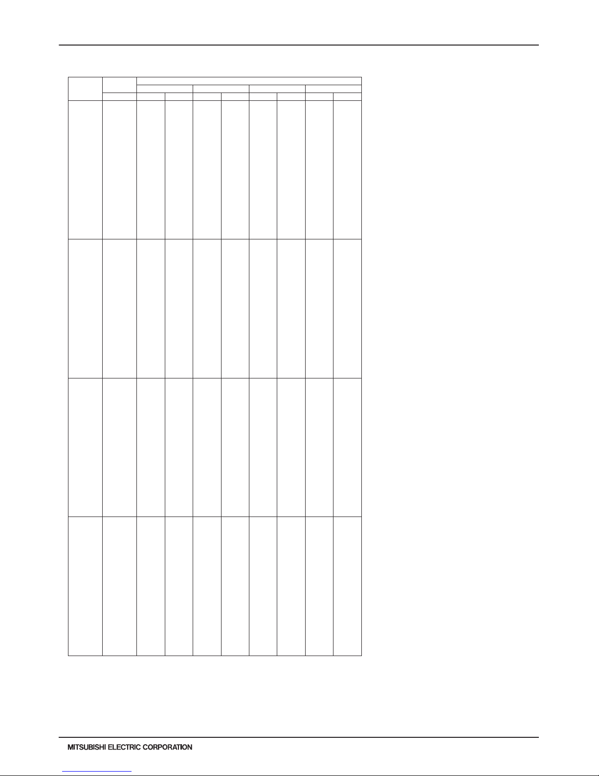
PURY-HP-T(S)KMU,-Y(S)KMU (September 2014)
H2i-R2-73
© 2014 Mitsubishi Electric US, Inc.
7. CAPACITY TABLES
7-4-9. Heating Capacity with PURY-HP72TKMU-A-H (cont.)
6. CAPACITY TABLES
DATA U10
H2i R2
110 -13.0 66400 39100 66300 40100 66400 39800 57600 34100
-9.0 70700 39300 70700 40300 67200 38300 57600 32200
-4.0 76000 39700 76100 40800 67200 35600 57600 30000
1.0 81300 40200 80000 40700 67200 33100 57600 27900
5.0 85300 40500 80000 38500 67200 31300 57600 26300
10.0 90400 41000 80000 35900 67200 29000 57600 24400
14.0 91200 39400 80000 33800 67200 27300 57600 22900
19.0 91200 36400 80000 31300 67200 25200 57600 21200
23.0 91200 34200 80000 29400 67200 23700 57600 19900
28.0 91200 31500 80000 27000 67200 21900 57600 18400
32.0 91200 29500 80000 25200 67200 20600 57600 17300
37.0 91200 27100 80000 22900 67200 19000 57600 15900
41.0 91200 25300 80000 21200 67200 17900 57600 15000
43.0 91200 24500 80000 20800 67200 17400 57600 14500
46.0 91200 23200 80000 19800 67200 16600 57600 13900
50.0 91200 21600 80000 18800 67200 15600 57600 13000
55.0 94900 21900 80000 17800 67200 14500 57600 12100
59.0 99200 22000 80000 17200 67200 13800 57600 11500
100 -13.0 66200 40200 66100 41300 66200 41000 57500 35100
-9.0 70500 40500 70600 41500 67000 39400 57500 33200
-4.0 75800 40900 75900 42000 67000 36700 57500 30900
1.0 81100 41400 80000 41900 67000 34100 57500 28700
5.0 85100 41800 80000 39700 67000 32200 57500 27100
10.0 90100 42300 80000 37000 67000 29800 57500 25100
14.0 91000 40600 80000 34900 67000 28100 57500 23600
19.0 91000 37500 80000 32300 67000 26000 57500 21800
23.0 91000 35200 80000 30300 67000 24400 57500 20500
28.0 91000 32500 80000 27800 67000 22600 57500 18900
32.0 91000 30400 80000 26000 67000 21200 57500 17800
37.0 91000 27900 80000 23600 67000 19600 57500 16400
41.0 91000 26100 80000 21900 67000 18400 57500 15400
43.0 91000 25200 80000 21400 67000 17900 57500 15000
46.0 91000 23900 80000 20400 67000 17100 57500 14300
50.0 91000 22300 80000 19400 67000 16100 57500 13400
55.0 94700 22600 80000 18300 67000 15000 57500 12500
59.0 99000 22700 80000 17700 67000 14200 57500 11800
90 -13.0 59600 35500 59500 36400 59600 36100 51700 31000
-9.0 63400 35700 63500 36600 60300 34800 51700 29300
-4.0 68300 36100 68300 37100 60300 32400 51700 27300
1.0 73000 36500 71800 36900 60300 30100 51700 25300
5.0 76600 36800 71800 35000 60300 28400 51700 23900
10.0 81100 37300 71800 32600 60300 26300 51700 22100
14.0 81900 35800 71800 30700 60300 24800 51700 20800
19.0 81900 33100 71800 28400 60300 22900 51700 19300
23.0 81900 31100 71800 26700 60300 21600 51700 18100
28.0 81900 28600 71800 24500 60300 19900 51700 16700
32.0 81900 26800 71800 22900 60300 18700 51700 15700
37.0 81900 24600 71800 20800 60300 17300 51700 14500
41.0 81900 23000 71800 19300 60300 16300 51700 13600
43.0 81900 22200 71800 18900 60300 15800 51700 13200
46.0 81900 21000 71800 18000 60300 15100 51700 12600
50.0 81900 19600 71800 17100 60300 14200 51700 11800
55.0 85200 19900 71800 16100 60300 13200 51700 11000
59.0 89100 20000 71800 15600 60300 12500 51700 10400
80 -13.0 53000 31100 52900 31900 53000 31600 46000 27100
-9.0 56400 31300 56500 32100 53600 30400 46000 25600
-4.0 60700 31600 60700 32400 53600 28300 46000 23900
1.0 64900 31900 63800 32300 53600 26300 46000 22200
5.0 68100 32200 63800 30600 53600 24800 46000 20900
10.0 72100 32600 63800 28500 53600 23000 46000 19400
14.0 72800 31300 63800 26900 53600 21700 46000 18200
19.0 72800 29000 63800 24900 53600 20100 46000 16900
23.0 72800 27200 63800 23400 53600 18900 46000 15800
28.0 72800 25100 63800 21500 53600 17400 46000 14600
32.0 72800 23500 63800 20000 53600 16400 46000 13700
37.0 72800 21500 63800 18200 53600 15100 46000 12700
41.0 72800 20100 63800 16900 53600 14200 46000 11900
43.0 72800 19400 63800 16500 53600 13800 46000 11500
46.0 72800 18400 63800 15800 53600 13200 46000 11000
50.0 72800 17200 63800 14900 53600 12400 46000 10400
55.0 75700 17400 63800 14100 53600 11600 46000 9600
59.0 79200 17500 63800 13700 53600 10900 46000 9100
PURY-HP72TKMU-A-H
TC:Total Capacity(BTU), PI:Power Input(BTU)
Combination Outdoor Indoor air temp.
(%) air temp. 59°F D.B. 70°F D.B. 77°F D.B. 81°F D.B.
°F W.B. TC PI TC PI TC PI TC PI
kcal/h=kW x 860 , BTU/h = kW x 3,412
Page 74

H2i-R2-74
PURY-HP-T(S)KMU,-Y(S)KMU (September 2014)
© 2014 Mitsubishi Electric US, Inc.
7. CAPACITY TABLES
7-4-9. Heating Capacity with PURY-HP72TKMU-A-H (cont.)
6. CAPACITY TABLES
DATA U10
70 -13.0 46300 27000 46300 27700 46400 27500 40200 23600
-9.0 49300 27200 49400 27900 46900 26500 40200 22300
-4.0 53100 27500 53100 28200 46900 24600 40200 20700
1.0 56800 27800 55900 28100 46900 22900 40200 19300
5.0 59600 28000 55900 26600 46900 21600 40200 18200
10.0 63100 28400 5 5900 24800 46900 20000 40200 16800
14.0 63700 27200 5 5900 23400 46900 18900 40200 15800
19.0 63700 25200 5 5900 21600 46900 17400 40200 14600
23.0 63700 23600 5 5900 20300 46900 16400 40200 13800
28.0 63700 21800 5 5900 18700 46900 15200 40200 12700
32.0 63700 20400 5 5900 17400 46900 14200 40200 11900
37.0 63700 18700 5 5900 15900 46900 13200 40200 11000
41.0 63700 17500 5 5900 14700 46900 12400 40200 10400
43.0 63700 16900 5 5900 14400 46900 12000 40200 10000
46.0 63700 16000 5 5900 13700 46900 11500 40200 9600
50.0 63700 14900 5 5900 13000 46900 10800 40200 9000
55.0 66300 15200 5 5900 12300 46900 10000 40200 8400
59.0 69300 15200 5 5900 11900 46900 950 0 40200 7900
60 -13.0 39700 23300 39700 23900 39800 23700 34500 20300
-9.0 42300 23400 42400 24000 40200 22800 34500 19200
-4.0 45500 23700 45600 24300 40200 21200 34500 17900
1.0 48700 23900 47900 24200 40200 19700 34500 16600
5.0 51100 24100 47900 23000 40200 18600 34500 15700
10.0 54100 24400 4 7900 21400 40200 17300 34500 14500
14.0 54600 23500 4 7900 20200 40200 16300 34500 13700
19.0 54600 21700 4 7900 18700 40200 15000 34500 12600
23.0 54600 20400 4 7900 17500 40200 14100 34500 11900
28.0 54600 18800 4 7900 16100 40200 13100 34500 11000
32.0 54600 17600 4 7900 15000 40200 12300 34500 10300
37.0 54600 16100 4 7900 13700 40200 11300 34500 9500
41.0 54600 15100 4 7900 12600 40200 10700 34500 8900
43.0 54600 14600 4 7900 12400 40200 10300 34500 8700
46.0 54600 13800 4 7900 11800 40200 990 0 34500 8300
50.0 54600 12900 4 7900 11200 40200 930 0 34500 7800
55.0 56800 13100 4 7900 10600 40200 870 0 34500 7200
59.0 59400 13100 4 7900 10300 40200 820 0 34500 6800
50 -13.0 33100 19900 33100 20400 33100 20300 28700 17400
-9.0 35300 20000 35300 20500 33500 19500 28700 16400
-4.0 37900 20200 38000 20800 33500 18100 28700 15300
1.0 40600 20500 39900 20700 33500 16900 28700 14200
5.0 42600 20600 39900 19600 33500 15900 28700 13400
10.0 45100 20900 3 9900 18300 33500 14800 28700 12400
14.0 45500 20100 3 9900 17200 33500 13900 28700 11700
19.0 45500 18500 3 9900 16000 33500 12900 28700 10800
23.0 45500 17400 3 9900 15000 33500 12100 28700 10100
28.0 45500 16000 3 9900 13800 33500 11200 28700 9400
32.0 45500 15000 3 9900 12800 33500 10500 28700 8800
37.0 45500 13800 3 9900 11700 33500 970 0 28700 8100
41.0 45500 12900 3 9900 10800 33500 910 0 28700 7600
43.0 45500 12500 3 9900 10600 33500 880 0 28700 7400
46.0 45500 11800 3 9900 10100 33500 840 0 28700 7100
50.0 45500 11000 3 9900 9600 33500 8000 28700 6600
55.0 47300 11200 3 9900 9100 33500 7400 28700 6200
59.0 49500 11200 3 9900 8800 33500 7000 28700 5800
PURY-HP72TKMU-A-H TC:Total Capacity(BTU), PI:Power Input(BTU)
Combination Outdoor Indoor air temp.
(%) air temp. 59°F D.B. 70°F D.B. 77°F D.B. 81°F D.B.
°F W.B. TC PI TC PI TC PI TC PI
kcal/h=kW x 860 , BTU/h = kW x 3,412
Page 75

PURY-HP-T(S)KMU,-Y(S)KMU (September 2014)
H2i-R2-75
© 2014 Mitsubishi Electric US, Inc.
7. CAPACITY TABLES
7-4-10. Heating Capacity with PURY-HP96TKMU-A-H
6. CAPACITY TABLES
DATA U10
PURY-HP96TKMU-A-H TC:Total Capacity(BTU), PI:Power Input(BTU)
Combination Outdoor Indoor air temp.
(%) air temp. 59°F D.B. 70°F D.B. 77°F D.B. 81°F D.B.
°F W.B. TC PI TC PI TC PI TC PI
150 -13.0 89800 52400 89700 53800 89900 53400 78000 45700
-9.0 95600 52800 95800 54100 91000 51400 78000 43300
-4.0 102900 53300 103000 54700 91000 47800 78000 40300
1.0 110000 53900 108300 54600 91000 44400 78000 3 7400
5.0 115500 54400 108300 51700 91000 41900 78000 3 5300
10.0 122300 55000 108300 48100 91000 38900 78000 327 00
14.0 123400 52800 108300 45400 91000 36600 78000 308 00
19.0 123400 48900 108300 42000 91000 33900 78000 284 00
23.0 123400 45900 108300 39400 91000 31800 78000 267 00
28.0 123400 42300 108300 36200 91000 29400 78000 247 00
32.0 123400 39600 108300 33800 91000 27600 78000 232 00
37.0 123400 36400 108300 30800 91000 25500 78000 214 00
41.0 123400 34000 108300 28500 91000 24000 78000 201 00
43.0 123400 32800 108300 27900 91000 23300 78000 195 00
46.0 123400 31100 108300 26600 91000 22200 78000 186 00
50.0 123400 29000 108300 25200 91000 21000 78000 175 00
55.0 128400 29400 108300 23800 91000 19500 78000 163 00
59.0 134300 29500 108300 23100 91000 18500 78000 154 00
140 -13.0 89900 53000 898 00 54400 8 9900 54000 7 8000 46300
-9.0 95700 53400 95800 54700 91000 52000 78000 43800
-4.0 103000 53900 103000 55400 91000 48400 78000 40700
1.0 110100 54500 108300 55200 91000 45000 78000 3 7800
5.0 115600 55000 108300 52300 91000 42400 78000 3 5700
10.0 122400 55700 108300 48700 91000 39300 78000 331 00
14.0 123500 53500 108300 45900 91000 37000 78000 311 00
19.0 123500 49400 108300 42500 91000 34300 78000 288 00
23.0 123500 46400 108300 39900 91000 32200 78000 270 00
28.0 123500 42800 108300 36700 91000 29800 78000 250 00
32.0 123500 40100 108300 34200 91000 28000 78000 234 00
37.0 123500 36800 108300 31100 91000 25800 78000 216 00
41.0 123500 34400 108300 28800 91000 24300 78000 203 00
43.0 123500 33200 108300 28200 91000 23600 78000 197 00
46.0 123500 31500 108300 26900 91000 22500 78000 188 00
50.0 123500 29300 108300 25500 91000 21200 78000 177 00
55.0 128500 29800 108300 24100 91000 19700 78000 164 00
59.0 134300 29900 108300 23400 91000 18700 78000 156 00
130 -13.0 89900 53800 898 00 55200 8 9900 54800 7 8000 46900
-9.0 95700 54200 95800 55500 91000 527 00 78000 444 00
-4.0 103000 54700 103100 56200 91000 49100 78000 41300
1.0 110100 55300 108300 56000 91000 45600 78000 38400
5.0 115600 55800 108300 53000 91000 43000 78000 36200
10.0 122400 56500 108300 49400 91000 39900 78000 335 00
14.0 123500 54200 108300 46600 91000 37600 78000 316 00
19.0 123500 50100 108300 43100 91000 34800 78000 292 00
23.0 123500 47100 108300 40500 91000 32700 78000 274 00
28.0 123500 43400 108300 37200 91000 30200 78000 253 00
32.0 123500 40600 108300 34700 91000 28400 78000 238 00
37.0 123500 37300 108300 31600 91000 26200 78000 220 00
41.0 123500 34800 108300 29200 91000 24700 78000 206 00
43.0 123500 33700 108300 28600 91000 23900 78000 200 00
46.0 123500 31900 108300 27300 91000 22800 78000 191 00
50.0 123500 29700 108300 25900 91000 21500 78000 180 00
55.0 128500 30200 108300 24500 91000 20000 78000 167 00
59.0 134400 30300 108300 23700 91000 19000 78000 158 00
120 -13.0 89900 54700 898 00 56200 8 9900 55700 7 8000 47700
-9.0 95700 55100 95800 56400 91000 53600 78000 45200
-4.0 103000 55600 103000 57100 91000 49900 78000 42000
1.0 110100 56300 108300 56900 91000 46400 78000 3 9000
5.0 115600 56800 108300 54000 91000 43800 78000 3 6800
10.0 122400 57500 108300 50200 91000 40600 78000 341 00
14.0 123500 55100 108300 47400 91000 38200 78000 321 00
19.0 123500 51000 108300 43900 91000 35300 78000 297 00
23.0 123500 47900 108300 41200 91000 33200 78000 279 00
28.0 123500 44100 108300 37800 91000 30700 78000 258 00
32.0 123500 41300 108300 35300 91000 28900 78000 242 00
37.0 123500 37900 108300 32100 91000 26700 78000 223 00
41.0 123500 35400 108300 29700 91000 25100 78000 210 00
43.0 123500 34200 108300 29100 91000 24300 78000 203 00
46.0 123500 32400 108300 27800 91000 23200 78000 194 00
50.0 123500 30200 108300 26300 91000 21900 78000 183 00
55.0 128500 30700 108300 24900 91000 20300 78000 170 00
59.0 134300 30800 108300 24100 91000 19300 78000 160 00
kcal/h=kW x 860 , BTU/h = kW x 3,412
Page 76

H2i-R2-76
PURY-HP-T(S)KMU,-Y(S)KMU (September 2014)
© 2014 Mitsubishi Electric US, Inc.
7. CAPACITY TABLES
7-4-10. Heating Capacity with PURY-HP96TKMU-A-H (cont.)
6. CAPACITY TABLES
DATA U10
H2i R2
110 -13.0 89800 55800 89700 57200 89900 56800 78000 48700
-9.0 95600 56200 95800 57500 91000 54700 78000 46000
-4.0 102900 56700 103000 58200 91000 50900 78000 42800
1.0 110000 57300 108300 58100 91000 47300 78000 39800
5.0 115500 57900 108300 55000 91000 44600 78000 37500
10.0 122300 58600 108300 51200 91000 41400 78000 34800
14.0 123400 56200 108300 48300 91000 38900 78000 32700
19.0 123400 52000 108300 44700 91000 36000 78000 30300
23.0 123400 48800 108300 42000 91000 33900 78000 28400
28.0 123400 45000 108300 38600 91000 31300 78000 26300
32.0 123400 42100 108300 36000 91000 29400 78000 24700
37.0 123400 38700 108300 32700 91000 27200 78000 22800
41.0 123400 36100 108300 30300 91000 25600 78000 21400
43.0 123400 34900 108300 29700 91000 24800 78000 20700
46.0 123400 33100 108300 28300 91000 23700 78000 19800
50.0 123400 30800 108300 26800 91000 22300 78000 18600
55.0 128400 31300 108300 25400 91000 20700 78000 17300
59.0 134300 31400 108300 24600 91000 19700 78000 16400
100 -13.0 89700 57000 89700 58500 89800 58000 77900 49700
-9.0 95600 57400 95700 58800 90900 55800 77900 47000
-4.0 102800 58000 102900 59500 90900 52000 77900 4380 0
1.0 109900 58600 108000 59300 90900 48300 77900 40700
5.0 115400 59100 108000 56200 90900 45600 77900 38300
10.0 122200 59800 108000 52300 9090 0 42300 7790 0 35500
14.0 123300 57400 108000 49400 9090 0 39800 7790 0 33400
19.0 123300 53100 108000 45700 9090 0 36800 7790 0 30900
23.0 123300 49900 108000 42900 9090 0 34600 7790 0 29100
28.0 123300 46000 108000 39400 9090 0 32000 7790 0 26800
32.0 123300 43000 108000 36700 9090 0 30100 7790 0 25200
37.0 123300 39500 108000 33500 9090 0 27800 7790 0 23300
41.0 123300 36900 108000 31000 9090 0 26100 7790 0 21800
43.0 123300 35700 108000 30300 9090 0 25300 7790 0 21200
46.0 123300 33800 108000 28900 9090 0 24200 7790 0 20200
50.0 123300 31500 108000 27400 9090 0 22800 7790 0 19000
55.0 128300 32000 108000 25900 9090 0 21200 7790 0 17700
59.0 134200 32100 108000 25100 9090 0 20100 7790 0 16700
90 -13.0 80800 49300 80700 50600 80800 50200 70100 43000
-9.0 86000 49700 86100 50900 81800 48300 70100 40700
-4.0 92600 50200 92600 51500 81800 45000 70100 37900
1.0 99000 50700 97400 51300 81800 41800 70100 35200
5.0 103900 51200 97400 48 600 81800 39400 70100 33200
10.0 110000 51800 97400 45300 81800 36600 70100 30700
14.0 111000 49700 97400 42700 81800 34400 70100 28900
19.0 111000 46000 97400 39500 81800 31900 70100 26800
23.0 111000 43200 97400 37100 81800 30000 70100 25100
28.0 111000 39800 97400 34100 81800 27700 70100 23200
32.0 111000 37200 97400 31800 81800 26000 70100 21800
37.0 111000 34200 97400 29000 81800 24000 70100 20100
41.0 111000 31900 97400 26800 81800 22600 70100 18900
43.0 111000 30900 97400 26200 81800 21900 70100 18300
46.0 111000 29200 97400 25000 81800 20900 70100 17500
50.0 111000 27300 97400 23700 81800 19700 70100 16500
55.0 115500 27700 97400 22400 81800 18300 70100 15300
59.0 120800 27800 97400 21700 81800 17400 70100 14500
80 -13.0 71800 42300 71800 43400 71900 43100 62300 36900
-9.0 76500 42600 76600 43700 72700 41500 62300 34900
-4.0 82300 43000 82300 44200 72700 38600 62300 32500
1.0 88000 43500 86600 44000 72700 35900 62300 30200
5.0 92300 43900 86600 41700 72700 33800 62300 28500
10.0 97800 44400 86600 38900 72700 31400 62300 26400
14.0 98700 42700 86600 36700 72700 29600 62300 24800
19.0 98700 39400 86600 33900 72700 27300 62300 23000
23.0 98700 37000 86600 31800 72700 25700 62300 21600
28.0 98700 34100 86600 29300 72700 23800 62300 19900
32.0 98700 32000 86600 27300 72700 22300 62300 18700
37.0 98700 29300 86600 24800 72700 20600 62300 17300
41.0 98700 27400 86600 23000 72700 19400 62300 16200
43.0 98700 26500 86600 22500 72700 18800 62300 15700
46.0 98700 25100 86600 21500 72700 18000 62300 15000
50.0 98700 23400 86600 20400 72700 16900 62300 14100
55.0 102700 23800 86600 1930 0 72700 15 700 62300 13100
59.0 107400 23900 86600 1860 0 72700 14 900 62300 12400
PURY-HP96TKMU-A-H TC:Total Capacity(BTU), PI:Power Input(BTU)
Combination Outdoor Indoor air temp.
(%) air temp. 59°F D.B. 70°F D.B. 77°F D.B. 81°F D.B.
°F W.B. TC PI TC PI TC PI TC PI
kcal/h=kW x 860 , BTU/h = kW x 3,412
Page 77

PURY-HP-T(S)KMU,-Y(S)KMU (September 2014)
H2i-R2-77
© 2014 Mitsubishi Electric US, Inc.
7. CAPACITY TABLES
7-4-10. Heating Capacity with PURY-HP96TKMU-A-H (cont.)
6. CAPACITY TABLES
DATA U10
70 -13.0 62800 36000 62800 37000 62900 36700 54500 31400
-9.0 66900 36300 67000 37200 63600 35300 54500 29700
-4.0 72000 36600 72000 37600 63600 32900 54500 27700
1.0 77000 37000 75800 37500 63600 30500 54500 25700
5.0 80800 37400 75800 35500 63600 28800 54500 24200
10.0 85600 37800 7 5800 33100 63600 26700 54500 22500
14.0 86400 36300 7 5800 31200 63600 25100 54500 21100
19.0 86400 33600 7 5800 28900 63600 23300 54500 19500
23.0 86400 31500 7 5800 27100 63600 21900 54500 18400
28.0 86400 29000 7 5800 24900 63600 20200 54500 17000
32.0 86400 27200 7 5800 23200 63600 19000 54500 15900
37.0 86400 25000 7 5800 21100 63600 17600 54500 14700
41.0 86400 23300 7 5800 19600 63600 16500 54500 13800
43.0 86400 22500 7 5800 19100 63600 16000 54500 13400
46.0 86400 21400 7 5800 18300 63600 15300 54500 12800
50.0 86400 19900 7 5800 17300 63600 14400 54500 12000
55.0 89900 20200 7 5800 16400 63600 13400 54500 11200
59.0 93900 20300 7 5800 15900 63600 12700 54500 10600
60 -13.0 53900 30400 53800 31200 53900 30900 46700 26500
-9.0 57300 30600 57400 31400 54500 29800 46700 25100
-4.0 61700 30900 61800 31700 54500 27700 46700 23300
1.0 66000 31200 64900 31600 54500 25800 46700 21700
5.0 69300 31500 64900 30000 54500 24300 46700 20400
10.0 73300 31900 6 4900 27900 54500 22500 46700 19000
14.0 74000 30600 6 4900 26300 54500 21200 46700 17800
19.0 74000 28300 6 4900 24400 54500 19600 46700 16500
23.0 74000 26600 6 4900 22900 54500 18500 46700 15500
28.0 74000 24500 6 4900 21000 54500 17100 46700 14300
32.0 74000 23000 6 4900 19600 54500 16000 46700 13400
37.0 74000 21100 6 4900 17800 54500 14800 46700 12400
41.0 74000 19700 6 4900 16500 54500 13900 46700 11700
43.0 74000 19000 6 4900 16200 54500 13500 46700 11300
46.0 74000 18000 6 4900 15400 54500 12900 46700 10800
50.0 74000 16800 6 4900 14600 54500 12200 46700 10100
55.0 77000 17100 6 4900 13800 54500 11300 46700 9400
59.0 80500 17100 6 4900 13400 54500 10700 46700 8900
50 -13.0 44900 25400 44800 26100 44900 25900 39000 22200
-9.0 47800 25600 47800 26300 45400 24900 39000 21000
-4.0 51400 25900 51500 26600 45400 23200 39000 19500
1.0 55000 26200 54100 26500 45400 21600 39000 18200
5.0 57700 26400 54100 25100 45400 20400 39000 17100
10.0 61100 26700 5 4100 23400 45400 18900 39000 15900
14.0 61700 25700 5 4100 22000 45400 17800 39000 14900
19.0 61700 23700 5 4100 20400 45400 16400 39000 13800
23.0 61700 22300 5 4100 19200 45400 15500 39000 13000
28.0 61700 20500 5 4100 17600 45400 14300 39000 12000
32.0 61700 19200 5 4100 16400 45400 13400 39000 11300
37.0 61700 17700 5 4100 14900 45400 12400 39000 10400
41.0 61700 16500 5 4100 13800 45400 11700 39000 9800
43.0 61700 15900 5 4100 13500 45400 11300 39000 9500
46.0 61700 15100 5 4100 12900 45400 10800 39000 9000
50.0 61700 14100 5 4100 12200 45400 10200 39000 8500
55.0 64200 14300 5 4100 11600 45400 950 0 39000 7900
59.0 67100 14300 5 4100 11200 45400 900 0 39000 7500
PURY-HP96TKMU-A-H TC:Total Capacity(BTU), PI:Power Input(BTU)
Combination Outdoor Indoor air temp.
(%) air temp. 59°F D.B. 70°F D.B. 77°F D.B. 81°F D.B.
°F W.B. TC PI TC PI TC PI TC PI
kcal/h=kW x 860 , BTU/h = kW x 3,412
Page 78

H2i-R2-78
PURY-HP-T(S)KMU,-Y(S)KMU (September 2014)
© 2014 Mitsubishi Electric US, Inc.
7. CAPACITY TABLES
7-4-11. Heating Capacity with PURY-HP144TSKMU-A-H
6. CAPACITY TABLES
DATA U10
PURY-HP144TSKMU-A-H TC:Total Capacity(BTU), PI:Power Input(BTU)
Combination Outdoor Indoor air temp.
(%) air temp. 59°F D.B. 70°F D.B. 77°F D.B. 81°F D.B.
°F W.B. TC PI TC PI TC PI TC PI
150 -13.0 134100 75600 134000 77600 134100 77000 116400 66000
-9.0 142800 76200 142900 78000 135800 74100 116400 62400
-4.0 153600 76900 153700 79000 135800 69000 116400 58100
1.0 164200 77800 161600 78700 135800 64100 116400 54000
5.0 172400 78500 161600 74600 135800 60500 116400 50900
10.0 182600 79400 161600 69400 135800 56100 116400 47200
14.0 184200 76200 161600 65500 135800 52800 116400 44400
19.0 184200 70500 161600 60600 135800 48900 116400 41000
23.0 184200 66200 161600 56900 135800 45900 116400 38600
28.0 184200 61000 161600 52300 135800 42400 116400 35600
32.0 184200 57100 161600 48800 135800 39900 116400 33400
37.0 184200 52400 161600 44400 135800 36900 116400 30900
41.0 184200 49000 161600 41100 135800 34700 116400 29000
43.0 184200 47300 161600 40200 135800 33600 116400 28100
46.0 184200 44800 161600 38400 135800 32100 116400 26800
50.0 184200 41800 161600 36400 135800 30200 116400 25200
55.0 191700 42400 161600 34400 135800 28100 116400 23400
59.0 200400 42600 161600 33300 135800 26600 116400 22200
140 -13.0 133800 76700 133700 78700 133900 78100 116200 66900
-9.0 142500 77200 142700 79100 135600 75100 116200 63300
-4.0 153400 78000 153500 80100 135600 70000 116200 58900
1.0 164000 78800 161400 79800 135600 65000 116200 54700
5.0 172100 79600 161400 75600 135600 61300 116200 51600
10.0 182300 80500 161400 70400 135600 56900 116200 47800
14.0 184000 77300 161400 66400 135600 53500 116200 45000
19.0 184000 71500 161400 61500 135600 49500 116200 41600
23.0 184000 67100 161400 57700 135600 46600 116200 39100
28.0 184000 61800 161400 53000 135600 43000 116200 36100
32.0 184000 57900 161400 49400 135600 40400 116200 33900
37.0 184000 53200 161400 45000 135600 37400 116200 31300
41.0 184000 49700 161400 41700 135600 35100 116200 29400
43.0 184000 48000 161400 40800 135600 34100 116200 28500
46.0 184000 45500 161400 38900 135600 32500 116200 27200
50.0 184000 42400 161400 36900 135600 30700 116200 25600
55.0 191400 43000 161400 34900 135600 28500 116200 23800
59.0 200100 43200 161400 33800 135600 27000 116200 22500
130 -13.0 133600 78100 133500 80200 133700 79500 116000 68100
-9.0 142300 78600 142500 80600 135300 76500 116000 64500
-4.0 153100 79400 153200 81500 135300 71200 116000 60000
1.0 163700 80300 161100 81300 135300 66200 116000 55700
5.0 171800 81000 161100 77000 135300 62500 116000 52500
10.0 182000 82000 161100 71700 135300 57900 116000 48700
14.0 183600 78700 161100 67600 135300 54500 116000 45800
19.0 183600 72800 161100 62600 135300 50500 116000 42400
23.0 183600 68400 161100 58800 135300 47400 116000 39800
28.0 183600 63000 161100 54000 135300 43800 116000 36800
32.0 183600 59000 161100 50400 135300 41200 116000 34500
37.0 183600 54200 161100 45900 135300 38100 116000 31900
41.0 183600 50600 161100 42400 135300 35800 116000 29900
43.0 183600 48900 161100 41500 135300 34700 116000 29000
46.0 183600 46300 161100 39600 135300 33100 116000 27700
50.0 183600 43200 161100 37600 135300 31200 116000 26100
55.0 191100 43800 161100 35500 135300 29000 116000 24200
59.0 199700 44000 161100 34400 135300 27500 116000 22900
120 -13.0 133300 79800 133200 82000 133400 81300 115700 69700
-9.0 142000 80400 142200 82400 135000 78300 115700 65900
-4.0 152800 81200 152900 83400 135000 72800 115700 61300
1.0 163300 82100 160800 83100 135000 67700 115700 57000
5.0 171500 82900 160800 78700 135000 63900 115700 53700
10.0 181600 83900 160800 73300 135000 59200 115700 49800
14.0 183300 80500 160800 69200 135000 55800 115700 46900
19.0 183300 74400 160800 64000 135000 51600 115700 43300
23.0 183300 69900 160800 60100 135000 48500 115700 40700
28.0 183300 64400 160800 55200 135000 44800 115700 37600
32.0 183300 60300 160800 51500 135000 42100 115700 35300
37.0 183300 55400 160800 46900 135000 38900 115700 32600
41.0 183300 51700 160800 43400 135000 36600 115700 30600
43.0 183300 50000 160800 42500 135000 35500 115700 29700
46.0 183300 47400 160800 40500 135000 33900 115700 28300
50.0 183300 44200 160800 38400 135000 31900 115700 26700
55.0 190700 44800 160800 36300 135000 29700 115700 24800
59.0 199300 45000 160800 35200 135000 28100 115700 23400
kcal/h=kW x 860 , BTU/h = kW x 3,412
Page 79

PURY-HP-T(S)KMU,-Y(S)KMU (September 2014)
H2i-R2-79
© 2014 Mitsubishi Electric US, Inc.
7. CAPACITY TABLES
7-4-11. Heating Capacity with PURY-HP144TSKMU-A-H (cont.)
6. CAPACITY TABLES
DATA U10
H2i R2
110 -13.0 133000 82 000 132900 84100 13 3100 83500 115500 71 500
-9.0 141700 82600 141800 84600 134700 80300 115500 67700
-4.0 152400 83400 152600 85600 134700 74800 115500 63000
1.0 163000 84300 160400 85300 134700 69500 115500 58500
5.0 171100 85000 160400 80800 134700 65600 115500 55200
10.0 181200 86100 160400 75300 134700 60800 115500 51100
14.0 182900 82600 160400 71000 134700 57200 115500 48100
19.0 182900 76400 160400 65700 134700 53000 115500 44500
23.0 182900 71800 160400 61700 134700 49800 115500 41800
28.0 182900 66100 160400 56700 134700 46000 115500 38600
32.0 182900 61900 160400 52900 134700 43200 115500 36200
37.0 182900 56800 160400 48100 134700 40000 115500 33500
41.0 182900 53100 160400 44500 134700 37600 115500 31400
43.0 182900 51300 160400 43600 134700 36400 115500 30500
46.0 182900 48600 160400 41600 134700 34800 115500 29100
50.0 182900 45300 160400 39400 134700 32800 115500 27400
55.0 190300 46000 160400 37300 134700 30500 115500 25400
59.0 198900 46200 160400 36100 134700 28900 115500 24000
100 -13.0 132700 84400 132600 86700 132800 86000 115200 73700
-9.0 141300 85000 141500 87100 134400 82700 115200 69700
-4.0 152100 85900 152200 88200 134400 77000 115200 64900
1.0 162600 86800 160000 87900 134400 71600 115200 60300
5.0 170700 87600 160000 83300 134400 67500 115200 56800
10.0 180800 88700 160000 77500 134400 62600 115200 52700
14.0 182400 85100 160000 73100 134400 59000 115200 49600
19.0 182400 78700 160000 67700 134400 54600 115200 45800
23.0 182400 73900 160000 63500 134400 51300 115200 43100
28.0 182400 68100 160000 58400 134400 47400 115200 39800
32.0 182400 63800 160000 54400 134400 44500 115200 37300
37.0 182400 58600 160000 49600 134400 41200 115200 34500
41.0 182400 54700 160000 45900 134400 38700 115200 32400
43.0 182400 52800 160000 44900 134400 37500 115200 31400
46.0 182400 50100 160000 42900 134400 35800 115200 29900
50.0 182400 46700 160000 40600 134400 33800 115200 28200
55.0 189800 47400 160000 38400 134400 31400 115200 26200
59.0 198400 47600 160000 37200 134400 29800 115200 24800
90 -13.0 119400 74400 119400 76400 119500 75800 103700 64900
-9.0 127200 75000 127400 76800 121000 73000 103700 61400
-4.0 136900 75700 137000 77700 121000 67900 103700 57200
1.0 146300 76500 144000 77500 121000 63100 103700 53100
5.0 153600 77200 144000 73400 121000 59500 103700 50100
10.0 162700 78200 144000 68400 121000 55200 103700 46400
14.0 164200 75000 144000 64500 121000 52000 103700 43700
19.0 164200 69400 144000 59700 121000 48100 103700 40400
23.0 164200 65200 144000 56000 121000 45200 103700 38000
28.0 164200 60000 144000 51500 121000 41800 103700 35100
32.0 164200 56200 144000 48000 121000 39300 103700 32900
37.0 164200 51600 144000 43700 121000 36300 103700 30400
41.0 164200 48200 144000 40400 121000 34100 103700 28500
43.0 164200 46600 144000 39600 121000 33100 103700 27700
46.0 164200 44200 144000 37800 121000 31600 103700 26400
50.0 164200 41200 144000 35800 121000 29800 103700 24900
55.0 170800 41800 144000 33900 121000 27700 103700 23100
59.0 178600 42000 144000 32800 121000 26200 103700 21800
80 -13.0 106200 65200 106100 66900 106200 66400 92200 56900
-9.0 113100 65600 113200 67200 107500 63900 92200 53800
-4.0 121700 66300 121800 68100 107500 59500 92200 50100
1.0 130100 67000 128000 67800 107500 55300 92200 46500
5.0 136500 67600 128000 64300 107500 52100 92200 43900
10.0 144600 68500 128000 59900 107 500 48300 92200 40600
14.0 145900 65700 128000 56500 107 500 45500 92200 38300
19.0 145900 60800 128000 52300 107 500 42100 92200 35400
23.0 145900 57100 128000 49000 107 500 39600 92200 33200
28.0 145900 52600 128000 45100 107 500 36600 92200 30700
32.0 145900 49200 128000 42000 107 500 34400 92200 28800
37.0 145900 45200 128000 38300 107 500 31800 92200 26600
41.0 145900 42200 128000 35400 107 500 29900 92200 25000
43.0 145900 40800 128000 34700 107 500 29000 92200 24200
46.0 145900 38700 128000 33100 107 500 27700 92200 23100
50.0 145900 36000 128000 31400 107 500 26100 92200 21800
55.0 151800 36600 128000 29700 107 500 24200 92200 20200
59.0 158700 36700 128000 28700 107 500 23000 92200 19100
PURY-HP144TSKMU-A-H TC:Total Capacity(BTU), PI:Power Input(BTU)
Combination Outdoor Indoor air temp.
(%) air temp. 59°F D.B. 70°F D.B. 77°F D.B. 81°F D.B.
°F W.B. TC PI TC PI TC PI TC PI
kcal/h=kW x 860 , BTU/h = kW x 3,412
Page 80
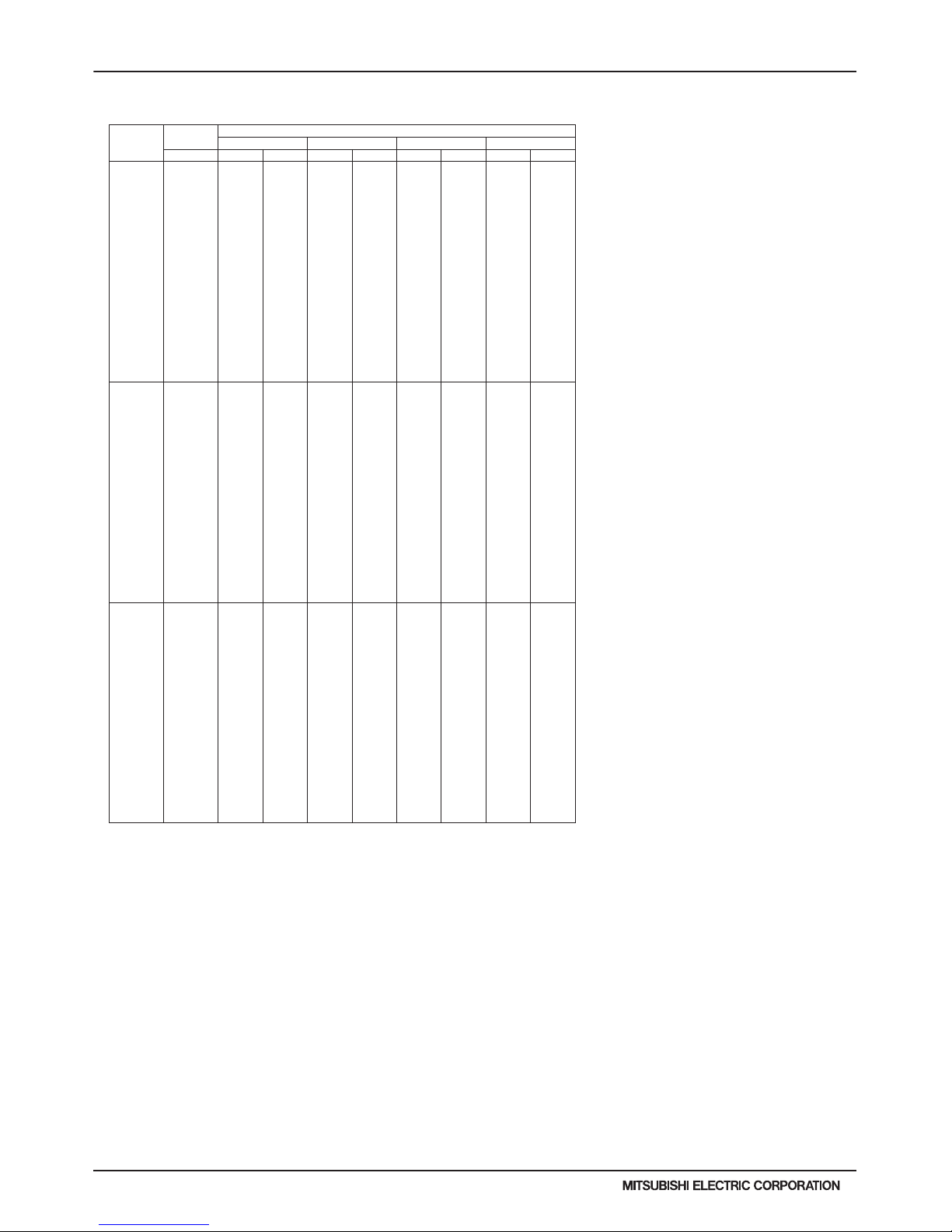
H2i-R2-80
PURY-HP-T(S)KMU,-Y(S)KMU (September 2014)
© 2014 Mitsubishi Electric US, Inc.
7. CAPACITY TABLES
7-4-11. Heating Capacity with PURY-HP144TSKMU-A-H (cont.)
6. CAPACITY TABLES
DATA U10
70 -13.0 92900 56600 92800 58100 93000 57700 80700 49400
-9.0 98900 57000 99100 58400 94100 55500 80700 46700
-4.0 106500 57600 106500 59100 94100 51700 80700 43500
1.0 113800 58200 112000 59000 94100 48000 80700 40400
5.0 119500 58800 112000 55900 94100 45300 80700 38100
10.0 126500 59500 112000 52000 94100 42000 80700 35300
14.0 127700 57100 112000 49100 94100 39600 80700 33200
19.0 127700 52800 112000 45400 94100 36600 80700 30700
23.0 127700 49600 112000 42600 94100 34400 80700 28900
28.0 127700 45700 112000 39200 94100 31800 80700 26700
32.0 127700 42800 112000 36500 94100 29900 80700 25000
37.0 127700 39300 112000 33300 94100 27600 80700 23100
41.0 127700 36700 112000 30800 94100 26000 80700 21700
43.0 127700 35400 112000 30100 94100 25200 80700 21100
46.0 127700 33600 112000 28800 94100 24000 80700 20100
50.0 127700 31300 112000 27200 94100 22700 80700 18900
55.0 132900 31800 112000 25800 94100 21100 80700 17600
59.0 138900 31900 112000 24900 94100 20000 80700 16600
60 -13.0 79600 48800 79600 50100 79700 49700 69100 42600
-9.0 84800 49200 84900 50400 80700 47800 69100 40300
-4.0 91300 49700 91300 51000 80700 44500 69100 37500
1.0 97600 50200 96000 50800 80700 41400 69100 34800
5.0 102400 50700 96000 48200 80700 39100 69100 32900
10.0 108500 51300 96000 44800 80700 36200 69100 30400
14.0 109500 49200 96000 42300 80700 34100 69100 28700
19.0 109500 45500 96000 39100 80700 31500 69100 26500
23.0 109500 42700 96000 36700 80700 29700 69100 24900
28.0 109500 39400 96000 33800 80700 27400 69100 23000
32.0 109500 36900 96000 31500 80700 25800 69100 21600
37.0 109500 33900 96000 28700 80700 23800 69100 19900
41.0 109500 31600 96000 26500 80700 22400 69100 18700
43.0 109500 30600 96000 26000 80700 21700 69100 18200
46.0 109500 29000 96000 24800 80700 20700 69100 17300
50.0 109500 27000 96000 23500 80700 19500 69100 16300
55.0 113900 27400 96000 22200 80700 18200 69100 15100
59.0 119100 27500 96000 21500 80700 17200 69100 14300
50 -13.0 66400 41700 66300 42800 66400 42500 57600 36400
-9.0 70700 42000 70800 43100 67200 40900 57600 34500
-4.0 76100 42500 76100 43600 67200 38100 57600 32100
1.0 81300 42900 80000 43400 67200 35400 57600 29800
5.0 85400 43300 80000 41200 67200 33400 57600 28100
10.0 90400 43800 80000 38300 67200 31000 57600 26000
14.0 91200 42100 80000 36200 67200 29100 57600 24500
19.0 91200 38900 80000 33500 67200 27000 57600 22700
23.0 91200 36500 80000 31400 67200 25400 57600 21300
28.0 91200 33700 80000 28900 67200 23400 57600 19700
32.0 91200 31500 80000 26900 67200 22000 57600 18500
37.0 91200 28900 80000 24500 67200 20300 57600 17000
41.0 91200 27000 80000 22700 67200 19100 57600 16000
43.0 91200 26100 80000 22200 67200 18600 57600 15500
46.0 91200 24800 80000 21200 67200 17700 57600 14800
50.0 91200 23100 80000 20100 67200 16700 57600 13900
55.0 94900 23400 80000 19000 67200 15500 57600 12900
59.0 99200 23500 80000 18400 67200 14700 57600 12200
PURY-HP144TSKMU-A-H TC:Total Capacity(BTU), PI:Power Input(BTU)
Combination Outdoor Indoor air temp.
(%) air temp. 59°F D.B. 70°F D.B. 77°F D.B. 81°F D.B.
°F W.B. TC PI TC PI TC PI TC PI
kcal/h=kW x 860 , BTU/h = kW x 3,412
Page 81

PURY-HP-T(S)KMU,-Y(S)KMU (September 2014)
H2i-R2-81
© 2014 Mitsubishi Electric US, Inc.
7. CAPACITY TABLES
7-4-12. Heating Capacity with PURY-HP192TSKMU-A-H
6. CAPACITY TABLES
DATA U10
PURY-HP192TSKMU-A-H TC:Total Capacity(BTU), PI:Power Input(BTU)
Combination Outdoor Indoor air temp.
(%) air temp. 59°F D.B. 70°F D.B. 77°F D.B. 81°F D.B.
°F W.B. TC PI TC PI TC PI TC PI
150 -13.0 178500 109300 178300 112200 178600 111300 154900 95400
-9.0 190000 110100 190300 112800 180700 107100 154900 90200
-4.0 204500 111200 204600 114200 180700 99700 154900 84000
1.0 218600 112400 215200 113800 180700 92700 154900 7 8000
5.0 229500 113400 215200 107800 180700 87500 154900 7 3600
10.0 243100 114800 215200 100400 180700 81100 154900 68200
14.0 245300 110200 215200 94700 1 80700 76300 154900 64200
19.0 245300 101900 215200 87700 1 80700 70600 154900 59300
23.0 245300 95700 215200 82300 180700 66400 154900 55800
28.0 245300 88200 215200 75600 180700 61400 154900 51500
32.0 245300 82600 215200 70500 180700 57700 154900 48300
37.0 245300 75800 215200 64200 180700 53300 154900 44600
41.0 245300 70800 215200 59400 180700 50100 154900 41900
43.0 245300 68400 215200 58100 180700 48600 154900 40600
46.0 245300 64800 215200 55500 180700 46400 154900 38800
50.0 245300 60500 215200 52600 180700 43700 154900 36500
55.0 255200 61400 215200 49700 180700 40700 154900 33900
59.0 266800 61600 215200 48200 180700 38500 154900 32100
140 -13.0 178500 110600 178400 113500 178700 112600 155000 96500
-9.0 190100 111400 190400 114100 180800 108400 155000 91300
-4.0 204600 112500 204700 115500 180800 100900 155000 85000
1.0 218700 113700 215300 115100 180800 93800 155000 7 8900
5.0 229600 114800 215300 109100 180800 88500 155000 7 4400
10.0 243200 116200 215300 101600 180800 82000 155000 69000
14.0 245400 111500 215300 95800 180800 77200 155000 64900
19.0 245400 103100 215300 88700 180800 71500 155000 60000
23.0 245400 96800 215300 83200 180800 67200 155000 56400
28.0 245400 89200 215300 76500 180800 62100 155000 52100
32.0 245400 83500 215300 71300 180800 58300 155000 48900
37.0 245400 76700 215300 64900 180800 53900 155000 45100
41.0 245400 71700 215300 60100 180800 50700 155000 42400
43.0 245400 69200 215300 58800 180800 49200 155000 41100
46.0 245400 65600 215300 56100 180800 46900 155000 39200
50.0 245400 61200 215300 53200 180800 44200 155000 36900
55.0 255300 62100 215300 50300 180800 41100 155000 34300
59.0 266900 62300 215300 48700 180800 39000 155000 32500
130 -13.0 178600 112200 178400 115200 178700 114300 155000 97900
-9.0 190200 113000 190400 115800 180800 110000 155000 92600
-4.0 204600 114100 204800 117200 180800 102400 155000 86200
1.0 218800 115400 215300 116800 180800 95100 155000 80100
5.0 229600 116400 215300 110700 180800 89700 155000 75500
10.0 243200 117800 215300 103000 180800 83200 155000 70000
14.0 245400 113100 215300 97200 1 80800 78300 155000 65800
19.0 245400 104600 215300 90000 1 80800 72500 155000 60900
23.0 245400 98200 215300 84400 180800 68200 155000 57200
28.0 245400 90500 215300 77600 180800 63000 155000 52800
32.0 245400 84700 215300 72300 180800 59200 155000 49600
37.0 245400 77800 215300 65900 180800 54700 155000 45800
41.0 245400 72700 215300 61000 180800 51400 155000 43000
43.0 245400 70200 215300 59700 180800 49900 155000 41700
46.0 245400 66500 215300 57000 180800 47600 155000 39800
50.0 245400 62000 215300 54000 180800 44900 155000 37500
55.0 255400 63000 215300 51100 180800 41700 155000 34800
59.0 267000 63200 215300 49400 180800 39500 155000 32900
120 -13.0 178500 114100 178400 117100 178700 116200 155000 99500
-9.0 190100 114900 190400 117700 180800 111800 155000 94200
-4.0 204600 116100 204700 119200 180800 104100 155000 87600
1.0 218700 117300 215300 118800 180800 96800 155000 8 1400
5.0 229600 118400 215300 112500 180800 91300 155000 7 6800
10.0 243200 119800 215300 104800 180800 84600 155000 71200
14.0 245400 115000 215300 98800 1 80800 79700 155000 67000
19.0 245400 106400 215300 91500 1 80800 73700 155000 61900
23.0 245400 99900 215300 85900 180800 69300 155000 58200
28.0 245400 92000 215300 78900 180800 64100 155000 53700
32.0 245400 86200 215300 73600 180800 60200 155000 50500
37.0 245400 79100 215300 67000 180800 55600 155000 46600
41.0 245400 73900 215300 62000 180800 52300 155000 43800
43.0 245400 71400 215300 60700 180800 50700 155000 42400
46.0 245400 67700 215300 57900 180800 48400 155000 40500
50.0 245400 63100 215300 54900 180800 45600 155000 38100
55.0 255300 64000 215300 51900 180800 42400 155000 35400
59.0 266900 64300 215300 50300 180800 40200 155000 33500
kcal/h=kW x 860 , BTU/h = kW x 3,412
Page 82

H2i-R2-82
PURY-HP-T(S)KMU,-Y(S)KMU (September 2014)
© 2014 Mitsubishi Electric US, Inc.
7. CAPACITY TABLES
7-4-12. Heating Capacity with PURY-HP192TSKMU-A-H (cont.)
6. CAPACITY TABLES
DATA U10
H2i R2
110 -13.0 178500 116300 178300 119400 178600 118500 154900 101500
-9.0 190000 117100 190300 120000 180700 114000 154900 96000
-4.0 204500 118300 204600 121500 180700 106100 154900 89300
1.0 218600 119600 215200 121100 180700 98600 154900 83000
5.0 229500 120700 215200 114700 180700 93000 154900 78300
10.0 243100 122200 215200 106800 180700 86300 154900 72500
14.0 245300 117300 215200 100800 180700 81200 154900 68300
19.0 245300 108400 215200 93 300 180700 75200 154 900 63100
23.0 245300 101800 215200 87 500 180700 70700 154 900 59300
28.0 245300 93800 215200 80400 180700 65300 154900 54800
32.0 245300 87900 215200 75000 180700 61400 154900 51400
37.0 245300 80700 215200 68300 180700 56700 154900 47500
41.0 245300 75400 215200 63200 180700 53300 154900 44600
43.0 245300 72800 215200 61900 180700 51700 154900 43200
46.0 245300 69000 215200 59000 180700 49400 154900 41200
50.0 245300 64300 215200 56000 180700 46500 154900 38800
55.0 255200 65300 215200 52900 180700 43300 154900 36100
59.0 266800 65600 215200 51200 180700 41000 154900 34100
100 -13.0 178300 118800 178200 122000 178500 121000 154800 103700
-9.0 189900 119700 190100 122600 180600 116500 154800 98100
-4.0 204300 120900 204500 124100 180600 108400 154800 91300
1.0 218500 122200 215000 123700 180600 100800 154800 84800
5.0 229300 123300 215000 117200 180600 95100 154800 80000
10.0 242900 124800 215000 109100 180600 88200 154800 74100
14.0 245100 119800 215000 103000 180600 83000 154800 69800
19.0 245100 110800 215000 95300 180600 76800 154800 64500
23.0 245100 104000 215000 89400 180600 72200 154800 60600
28.0 245100 95900 215000 82200 180600 66700 154800 56000
32.0 245100 89800 215000 76600 180600 62700 154800 52600
37.0 245100 82400 215000 69800 180600 57900 154800 48500
41.0 245100 77000 215000 64600 180600 54500 154800 45600
43.0 245100 74400 215000 63200 180600 52800 154800 44200
46.0 245100 70500 215000 60300 180600 50400 154800 42100
50.0 245100 65700 215000 57200 180600 47500 154800 39700
55.0 255000 66700 215000 54100 180600 44200 154800 36900
59.0 266600 67000 215000 52400 180600 41900 154800 34900
90 -13.0 160500 102800 160400 105600 160600 104700 139300 89700
-9.0 170900 103600 171100 106100 162600 100800 139300 84900
-4.0 183900 104600 184100 107400 162600 93800 139300 79000
1.0 196600 105800 193500 107100 162600 87200 139300 73400
5.0 206400 106700 193500 101400 162600 82300 139300 69200
10.0 218600 108000 193500 94400 162600 76300 139300 64100
14.0 220600 103700 193500 89100 162600 71800 139300 60400
19.0 220600 95900 193500 82500 162600 66500 139300 55800
23.0 220600 90000 193500 77400 162600 62500 139300 52400
28.0 220600 83000 193500 71100 162600 57700 139300 48400
32.0 220600 77700 193500 66300 162600 54300 139300 45500
37.0 220600 71300 193500 60400 162600 50100 139300 42000
41.0 220600 66600 193500 55900 162600 47100 139300 39400
43.0 220600 64400 193500 54700 162600 45700 139300 38200
46.0 220600 61000 193500 52200 162600 43600 139300 36500
50.0 220600 56900 193500 49500 162600 41100 139300 34300
55.0 229500 57700 193500 46800 162600 38300 139300 31900
59.0 240000 58000 193500 45300 162600 36200 139300 30200
80 -13.0 142700 88200 142600 90600 142800 89900 123900 77000
-9.0 151900 88900 152100 91100 144500 86500 123900 72900
-4.0 163500 89800 163600 92200 144500 80500 123900 67800
1.0 174800 90800 172000 91900 144500 74900 123900 63000
5.0 183500 91600 172000 87000 144500 70600 123900 59400
10.0 194300 92700 172000 81100 144500 65500 123900 55000
14.0 196100 89000 172000 76500 144500 61600 123900 51800
19.0 196100 82300 172000 70800 144500 57000 123900 47900
23.0 196100 77300 172000 66400 144500 53600 123900 45000
28.0 196100 71200 172000 61000 144500 49600 123900 41600
32.0 196100 66700 172000 56900 144500 46600 123900 39000
37.0 196100 61200 172000 51800 144500 43000 123900 36000
41.0 196100 57200 172000 48000 144500 40500 123900 33800
43.0 196100 55200 172000 46900 144500 39200 123900 32800
46.0 196100 52400 172000 44800 144500 37500 123900 31300
50.0 196100 48800 172000 42500 144500 35300 123900 29500
55.0 204000 49500 172000 40200 144500 32800 123900 27400
59.0 213300 49800 172000 38900 144500 31100 123900 25900
PURY-HP192TSKMU-A-H
TC:Total Capacity(BTU), PI:Power Input(BTU)
Combination Outdoor Indoor air temp.
(%) air temp. 59°F D.B. 70°F D.B. 77°F D.B. 81°F D.B.
°F W.B. TC PI TC PI TC PI TC PI
kcal/h=kW x 860 , BTU/h = kW x 3,412
Page 83
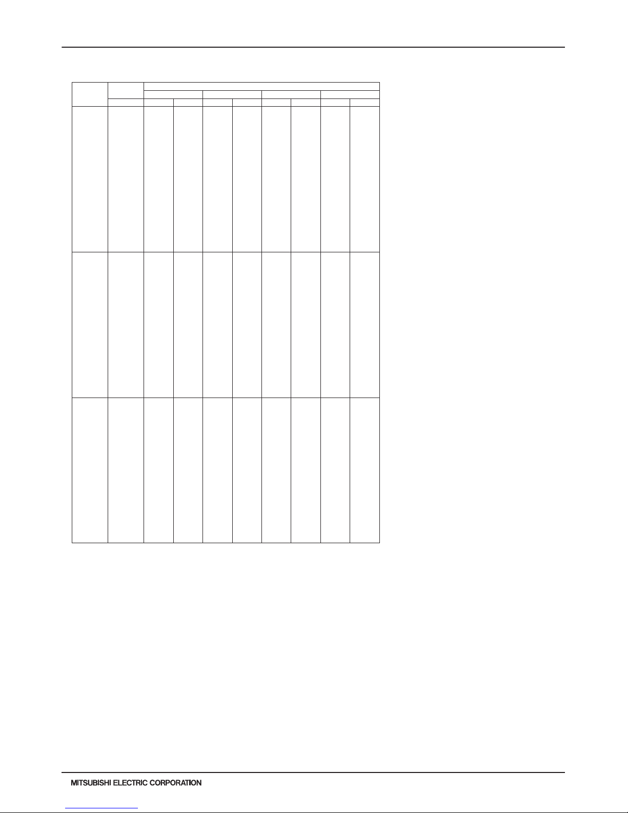
PURY-HP-T(S)KMU,-Y(S)KMU (September 2014)
H2i-R2-83
© 2014 Mitsubishi Electric US, Inc.
7. CAPACITY TABLES
7-4-12. Heating Capacity with PURY-HP192TSKMU-A-H (cont.)
6. CAPACITY TABLES
DATA U10
70 -13.0 124800 75100 124800 77100 124900 76500 108400 65500
-9.0 132900 75600 133100 77500 126400 73600 108400 62000
-4.0 143100 76400 143200 78400 126400 68500 108400 57700
1.0 152900 77200 150500 78200 126400 63700 108400 53600
5.0 160600 77900 150500 74100 126400 60100 108400 50500
10.0 170000 78900 150500 69000 126400 55700 108400 46800
14.0 171600 75700 150500 65100 126400 52500 108400 44100
19.0 171600 70000 150500 60200 126400 48500 108400 40800
23.0 171600 65800 150500 56500 126400 45600 108400 38300
28.0 171600 60600 150500 51900 126400 42200 108400 35400
32.0 171600 56700 150500 48400 126400 39600 108400 33200
37.0 171600 52100 150500 44100 126400 36600 108400 30700
41.0 171600 48700 150500 40800 126400 34400 108400 28800
43.0 171600 47000 150500 39900 126400 33400 108400 27900
46.0 171600 44600 150500 38100 126400 31900 108400 26600
50.0 171600 41500 150500 36100 126400 30000 108400 25100
55.0 178500 42200 150500 34200 126400 27900 108400 23300
59.0 186700 42300 150500 33100 126400 26500 108400 22000
60 -13.0 107000 63400 106900 65100 107100 64500 92900 55300
-9.0 114000 63800 114100 65400 108400 62100 92900 5 2300
-4.0 122600 64500 122700 66200 108400 57800 92900 4 8700
1.0 131100 65200 129000 66000 10 8400 53800 92900 45200
5.0 137600 65800 129000 62500 10 8400 50700 92900 42700
10.0 145700 66600 129000 58200 1084 00 47000 9 2900 39500
14.0 147100 63900 129000 54900 1084 00 44300 9 2900 37200
19.0 147100 59100 129000 50800 1084 00 41000 9 2900 34400
23.0 147100 55500 129000 47700 1084 00 38500 9 2900 32300
28.0 147100 51100 129000 43800 1084 00 35600 9 2900 29800
32.0 147100 47900 129000 40900 1084 00 33400 9 2900 28000
37.0 147100 44000 129000 37200 1084 00 30900 9 2900 25900
41.0 147100 41100 129000 34400 1084 00 29000 9 2900 24300
43.0 147100 39700 129000 33700 1084 00 28200 9 2900 23600
46.0 147100 37600 129000 32200 1084 00 26900 9 2900 22500
50.0 147100 35000 129000 30500 1084 00 25300 9 2900 21200
55.0 153000 35600 129000 28800 1084 00 23600 9 2900 19700
59.0 160000 35700 129000 27900 1084 00 22300 9 2900 18600
50 -13.0 89200 53100 89100 54500 89200 54100 77400 46300
-9.0 94900 53500 95100 54800 90300 52000 77400 43800
-4.0 102200 54000 102200 55400 90300 48400 77400 40800
1.0 109200 54600 107500 55300 90300 45000 77400 37900
5.0 114700 55100 107500 52400 90300 42500 77400 35700
10.0 121400 55800 107500 48700 90300 39400 77400 33100
14.0 122500 53500 107500 46000 90300 37100 77400 31200
19.0 122500 49500 107500 42600 90300 34300 77400 28800
23.0 122500 46500 107500 39900 90300 32200 77400 27100
28.0 122500 42800 107500 36700 90300 29800 77400 25000
32.0 122500 40100 107500 34200 90300 28000 77400 23500
37.0 122500 36800 107500 31200 90300 25900 77400 21700
41.0 122500 34400 107500 28800 90300 24300 77400 20400
43.0 122500 33200 107500 28200 90300 23600 77400 19700
46.0 122500 31500 107500 26900 90300 22500 77400 18800
50.0 122500 29400 107500 25500 90300 21200 77400 17700
55.0 127500 29800 107500 24200 90300 19700 77400 16500
59.0 133300 29900 107500 23400 90300 18700 77400 15600
PURY-HP192TSKMU-A-H TC:Total Capacity(BTU), PI:Power Input(BTU)
Combination Outdoor Indoor air temp.
(%) air temp. 59°F D.B. 70°F D.B. 77°F D.B. 81°F D.B.
°F W.B. TC PI TC PI TC PI TC PI
kcal/h=kW x 860 , BTU/h = kW x 3,412
Page 84

H2i-R2-84
PURY-HP-T(S)KMU,-Y(S)KMU (September 2014)
© 2014 Mitsubishi Electric US, Inc.
7. CAPACITY TABLES
7-4-13. Heating Capacity with PURY-HP72YKMU-A
6. CAPACITY TABLES
DATA U10
PURY-HP72YKMU-A TC:Total Capacity(BTU), PI:Power Input(BTU)
Combination Outdoor Indoor air temp.
(%) air temp. 59°F D.B. 70°F D.B. 77°F D.B. 81°F D.B.
°F W.B. TC PI TC PI TC PI TC PI
150 -13.0 66900 36000 66800 37000 66900 36700 58000 31400
-9.0 71200 36300 71300 37200 67700 35300 58000 29700
-4.0 76600 36700 76700 37600 67700 32900 58000 27700
1.0 81900 37100 80600 37500 677 00 30600 580 00 25700
5.0 86000 37400 80600 35500 677 00 28800 580 00 24300
10.0 91100 37900 80600 33100 67700 26700 58000 22500
14.0 91900 36300 80600 31200 67700 25200 58000 21200
19.0 91900 33600 80600 28900 67700 23300 58000 19600
23.0 91900 31500 80600 27100 67700 21900 58000 18400
28.0 91900 29100 80600 24900 67700 20200 58000 17000
32.0 91900 27200 80600 23200 67700 19000 58000 15900
37.0 91900 25000 80600 21200 67700 17600 58000 14700
41.0 91900 23300 80600 19600 67700 16500 58000 13800
43.0 91900 22600 80600 19200 67700 16000 58000 13400
46.0 91900 21400 80600 18300 67700 15300 58000 12800
50.0 91900 19900 80600 17300 67700 14400 58000 12000
55.0 95600 20200 80600 16400 67700 13400 58000 11200
59.0 100000 20300 80600 15900 67700 12700 58000 10600
140 -13.0 66800 36500 66700 37500 66800 37200 57900 31900
-9.0 71100 36800 712 00 37700 6 7600 35800 57900 30200
-4.0 76500 37200 765 00 38200 6 7600 33300 57900 28100
1.0 81800 37600 80500 38000 67600 31000 57900 26100
5.0 85800 37900 80500 36000 67600 29200 57900 24600
10.0 90900 38400 80500 33600 67600 27100 57900 22800
14.0 91800 36800 80500 31700 67600 25500 57900 21400
19.0 91800 34100 80500 29300 67600 23600 57900 19800
23.0 91800 32000 80500 27500 67600 22200 57900 18600
28.0 91800 29500 80500 25300 67600 20500 57900 17200
32.0 91800 27600 80500 23600 67600 19300 57900 16200
37.0 91800 25300 80500 21500 67600 17800 57900 14900
41.0 91800 23700 80500 19900 67600 16700 57900 14000
43.0 91800 22900 80500 19400 67600 16200 57900 13600
46.0 91800 21700 80500 18600 67600 15500 57900 13000
50.0 91800 20200 80500 17600 67600 14600 57900 12200
55.0 95500 20500 80500 16600 67600 13600 57900 11300
59.0 99800 20600 80500 16100 67600 12900 57900 10700
130 -13.0 66600 37200 66600 38200 66700 37900 57800 32500
-9.0 71000 37500 71000 38400 67500 36500 57800 30700
-4.0 76400 37900 76400 38900 67500 34000 57800 28600
1.0 81600 38300 80300 38700 67500 31600 57800 26600
5.0 85700 38600 80300 36700 67500 29800 57800 25000
10.0 90800 39100 80300 34200 67500 27600 57800 23200
14.0 91600 37500 80300 32200 67500 26000 57800 21800
19.0 91600 34700 80300 29800 67500 24000 57800 20200
23.0 91600 32600 80300 28000 67500 22600 57800 19000
28.0 91600 30000 80300 25700 67500 20900 57800 17500
32.0 91600 28100 80300 24000 67500 19600 57800 16500
37.0 91600 25800 80300 21900 67500 18100 57800 15200
41.0 91600 24100 80300 20200 67500 17100 57800 14300
43.0 91600 23300 80300 19800 67500 16500 57800 13800
46.0 91600 22100 80300 18900 67500 15800 57800 13200
50.0 91600 20600 80300 17900 67500 14900 57800 12400
55.0 95300 20900 80300 16900 67500 13800 57800 11500
59.0 99600 21000 80300 16400 67500 13100 57800 10900
120 -13.0 66500 38100 66500 39100 66500 38800 57700 33200
-9.0 70800 38300 709 00 39300 6 7300 37300 57700 31400
-4.0 76200 38700 763 00 39700 6 7300 34700 57700 29200
1.0 81500 39100 80200 39600 673 00 32300 577 00 27200
5.0 85500 39500 80200 37500 673 00 30400 577 00 25600
10.0 90600 40000 8 0200 34900 67300 28200 57700 23700
14.0 91400 38400 8 0200 33000 67300 26600 57700 22300
19.0 91400 35500 8 0200 30500 67300 24600 57700 20700
23.0 91400 33300 8 0200 28600 67300 23100 57700 19400
28.0 91400 30700 8 0200 26300 67300 21400 57700 17900
32.0 91400 28700 8 0200 24500 67300 20100 57700 16800
37.0 91400 26400 8 0200 22300 67300 18600 57700 15500
41.0 91400 24700 8 0200 20700 67300 17400 57700 14600
43.0 91400 23800 8 0200 20200 67300 16900 57700 14100
46.0 91400 22600 8 0200 19300 67300 16100 57700 13500
50.0 91400 21000 8 0200 18300 67300 15200 57700 12700
55.0 95100 21400 8 0200 17300 67300 14200 57700 11800
59.0 99400 21500 8 0200 16800 67300 13400 57700 11200
kcal/h=kW x 860 , BTU/h = kW x 3,412
Page 85

PURY-HP-T(S)KMU,-Y(S)KMU (September 2014)
H2i-R2-85
© 2014 Mitsubishi Electric US, Inc.
7. CAPACITY TABLES
7-4-13. Heating Capacity with PURY-HP72YKMU-A (cont.)
6. CAPACITY TABLES
DATA U10
H2i R2
110 -13.0 66400 39100 66300 40100 66400 39800 57600 34100
-9.0 70700 39300 70700 40300 67200 38300 57600 32200
-4.0 76000 39700 76100 40800 67200 35600 57600 30000
1.0 81300 40200 80000 40700 67200 33100 57600 27900
5.0 85300 40500 80000 38500 67200 31300 57600 26300
10.0 90400 41000 80000 35900 67200 29000 57600 24400
14.0 91200 39400 80000 33800 67200 27300 57600 22900
19.0 91200 36400 80000 31300 67200 25200 57600 21200
23.0 91200 34200 80000 29400 67200 23700 57600 19900
28.0 91200 31500 80000 27000 67200 21900 57600 18400
32.0 91200 29500 80000 25200 67200 20600 57600 17300
37.0 91200 27100 80000 22900 67200 19000 57600 15900
41.0 91200 25300 80000 21200 67200 17900 57600 15000
43.0 91200 24500 80000 20800 67200 17400 57600 14500
46.0 91200 23200 80000 19800 67200 16600 57600 13900
50.0 91200 21600 80000 18800 67200 15600 57600 13000
55.0 94900 21900 80000 17800 67200 14500 57600 12100
59.0 99200 22000 80000 17200 67200 13800 57600 11500
100 -13.0 66200 40200 66100 41300 66200 41000 57500 35100
-9.0 70500 40500 70600 41500 67000 39400 57500 33200
-4.0 75800 40900 75900 42000 67000 36700 57500 30900
1.0 81100 41400 80000 41900 67000 34100 57500 28700
5.0 85100 41800 80000 39700 67000 32200 57500 27100
10.0 90100 42300 80000 37000 67000 29800 57500 25100
14.0 91000 40600 80000 34900 67000 28100 57500 23600
19.0 91000 37500 80000 32300 67000 26000 57500 21800
23.0 91000 35200 80000 30300 67000 24400 57500 20500
28.0 91000 32500 80000 27800 67000 22600 57500 18900
32.0 91000 30400 80000 26000 67000 21200 57500 17800
37.0 91000 27900 80000 23600 67000 19600 57500 16400
41.0 91000 26100 80000 21900 67000 18400 57500 15400
43.0 91000 25200 80000 21400 67000 17900 57500 15000
46.0 91000 23900 80000 20400 67000 17100 57500 14300
50.0 91000 22300 80000 19400 67000 16100 57500 13400
55.0 94700 22600 80000 18300 67000 15000 57500 12500
59.0 99000 22700 80000 17700 67000 14200 57500 11800
90 -13.0 59600 35500 59500 36400 59600 36100 51700 31000
-9.0 63400 35700 63500 36600 60300 34800 51700 29300
-4.0 68300 36100 68300 37100 60300 32400 51700 27300
1.0 73000 36500 71800 36900 60300 30100 51700 25300
5.0 76600 36800 71800 35000 60300 28400 51700 23900
10.0 81100 37300 71800 32600 60300 26300 51700 22100
14.0 81900 35800 71800 30700 60300 24800 51700 20800
19.0 81900 33100 71800 28400 60300 22900 51700 19300
23.0 81900 31100 71800 26700 60300 21600 51700 18100
28.0 81900 28600 71800 24500 60300 19900 51700 16700
32.0 81900 26800 71800 22900 60300 18700 51700 15700
37.0 81900 24600 71800 20800 60300 17300 51700 14500
41.0 81900 23000 71800 19300 60300 16300 51700 13600
43.0 81900 22200 71800 18900 60300 15800 51700 13200
46.0 81900 21000 71800 18000 60300 15100 51700 12600
50.0 81900 19600 71800 17100 60300 14200 51700 11800
55.0 85200 19900 71800 16100 60300 13200 51700 11000
59.0 89100 20000 71800 15600 60300 12500 51700 10400
80 -13.0 53000 31100 52900 31900 53000 31600 46000 27100
-9.0 56400 31300 56500 32100 53600 30400 46000 25600
-4.0 60700 31600 60700 32400 53600 28300 46000 23900
1.0 64900 31900 63800 32300 53600 26300 46000 22200
5.0 68100 32200 63800 30600 53600 24800 46000 20900
10.0 72100 32600 63800 28500 53600 23000 46000 19400
14.0 72800 31300 63800 26900 53600 21700 46000 18200
19.0 72800 29000 63800 24900 53600 20100 46000 16900
23.0 72800 27200 63800 23400 53600 18900 46000 15800
28.0 72800 25100 63800 21500 53600 17400 46000 14600
32.0 72800 23500 63800 20000 53600 16400 46000 13700
37.0 72800 21500 63800 18200 53600 15100 46000 12700
41.0 72800 20100 63800 16900 53600 14200 46000 11900
43.0 72800 19400 63800 16500 53600 13800 46000 11500
46.0 72800 18400 63800 15800 53600 13200 46000 11000
50.0 72800 17200 63800 14900 53600 12400 46000 10400
55.0 75700 17400 63800 14100 53600 11600 46000 9600
59.0 79200 17500 63800 13700 53600 10900 46000 9100
PURY-HP72YKMU-A TC:Total Capacity(BTU), PI:Power Input(BTU)
Combination Outdoor Indoor air temp.
(%) air temp. 59°F D.B. 70°F D.B. 77°F D.B. 81°F D.B.
°F W.B. TC PI TC PI TC PI TC PI
kcal/h=kW x 860 , BTU/h = kW x 3,412
Page 86

H2i-R2-86
PURY-HP-T(S)KMU,-Y(S)KMU (September 2014)
© 2014 Mitsubishi Electric US, Inc.
7. CAPACITY TABLES
7-4-13. Heating Capacity with PURY-HP72YKMU-A (cont.)
6. CAPACITY TABLES
DATA U10
70 -13.0 46300 27000 46300 27700 46400 27500 40200 23600
-9.0 49300 27200 49400 27900 46900 26500 40200 22300
-4.0 53100 27500 53100 28200 46900 24600 40200 20700
1.0 56800 27800 55900 28100 46900 22900 40200 19300
5.0 59600 28000 55900 26600 46900 21600 40200 18200
10.0 63100 28400 5 5900 24800 46900 20000 40200 16800
14.0 63700 27200 5 5900 23400 46900 18900 40200 15800
19.0 63700 25200 5 5900 21600 46900 17400 40200 14600
23.0 63700 23600 5 5900 20300 46900 16400 40200 13800
28.0 63700 21800 5 5900 18700 46900 15200 40200 12700
32.0 63700 20400 5 5900 17400 46900 14200 40200 11900
37.0 63700 18700 5 5900 15900 46900 13200 40200 11000
41.0 63700 17500 5 5900 14700 46900 12400 40200 10400
43.0 63700 16900 5 5900 14400 46900 12000 40200 10000
46.0 63700 16000 5 5900 13700 46900 11500 40200 9600
50.0 63700 14900 5 5900 13000 46900 10800 40200 9000
55.0 66300 15200 5 5900 12300 46900 10000 40200 8400
59.0 69300 15200 5 5900 11900 46900 950 0 40200 7900
60 -13.0 39700 23300 39700 23900 39800 23700 34500 20300
-9.0 42300 23400 42400 24000 40200 22800 34500 19200
-4.0 45500 23700 45600 24300 40200 21200 34500 17900
1.0 48700 23900 47900 24200 40200 19700 34500 16600
5.0 51100 24100 47900 23000 40200 18600 34500 15700
10.0 54100 24400 4 7900 21400 40200 17300 34500 14500
14.0 54600 23500 4 7900 20200 40200 16300 34500 13700
19.0 54600 21700 4 7900 18700 40200 15000 34500 12600
23.0 54600 20400 4 7900 17500 40200 14100 34500 11900
28.0 54600 18800 4 7900 16100 40200 13100 34500 11000
32.0 54600 17600 4 7900 15000 40200 12300 34500 10300
37.0 54600 16100 4 7900 13700 40200 11300 34500 9500
41.0 54600 15100 4 7900 12600 40200 10700 34500 8900
43.0 54600 14600 4 7900 12400 40200 10300 34500 8700
46.0 54600 13800 4 7900 11800 40200 990 0 34500 8300
50.0 54600 12900 4 7900 11200 40200 930 0 34500 7800
55.0 56800 13100 4 7900 10600 40200 870 0 34500 7200
59.0 59400 13100 4 7900 10300 40200 820 0 34500 6800
50 -13.0 33100 19900 33100 20400 33100 20300 28700 17400
-9.0 35300 20000 35300 20500 33500 19500 28700 16400
-4.0 37900 20200 38000 20800 33500 18100 28700 15300
1.0 40600 20500 39900 20700 33500 16900 28700 14200
5.0 42600 20600 39900 19600 33500 15900 28700 13400
10.0 45100 20900 3 9900 18300 33500 14800 28700 12400
14.0 45500 20100 3 9900 17200 33500 13900 28700 11700
19.0 45500 18500 3 9900 16000 33500 12900 28700 10800
23.0 45500 17400 3 9900 15000 33500 12100 28700 10100
28.0 45500 16000 3 9900 13800 33500 11200 28700 9400
32.0 45500 15000 3 9900 12800 33500 10500 28700 8800
37.0 45500 13800 3 9900 11700 33500 970 0 28700 8100
41.0 45500 12900 3 9900 10800 33500 910 0 28700 7600
43.0 45500 12500 3 9900 10600 33500 880 0 28700 7400
46.0 45500 11800 3 9900 10100 33500 840 0 28700 7100
50.0 45500 11000 3 9900 9600 33500 8000 28700 6600
55.0 47300 11200 3 9900 9100 33500 7400 28700 6200
59.0 49500 11200 3 9900 8800 33500 7000 28700 5800
PURY-HP72YKMU-A TC:Total Capacity(BTU), PI:Power Input(BTU)
Combination Outdoor Indoor air temp.
(%) air temp. 59°F D.B. 70°F D.B. 77°F D.B. 81°F D.B.
°F W.B. TC PI TC PI TC PI TC PI
kcal/h=kW x 860 , BTU/h = kW x 3,412
Page 87
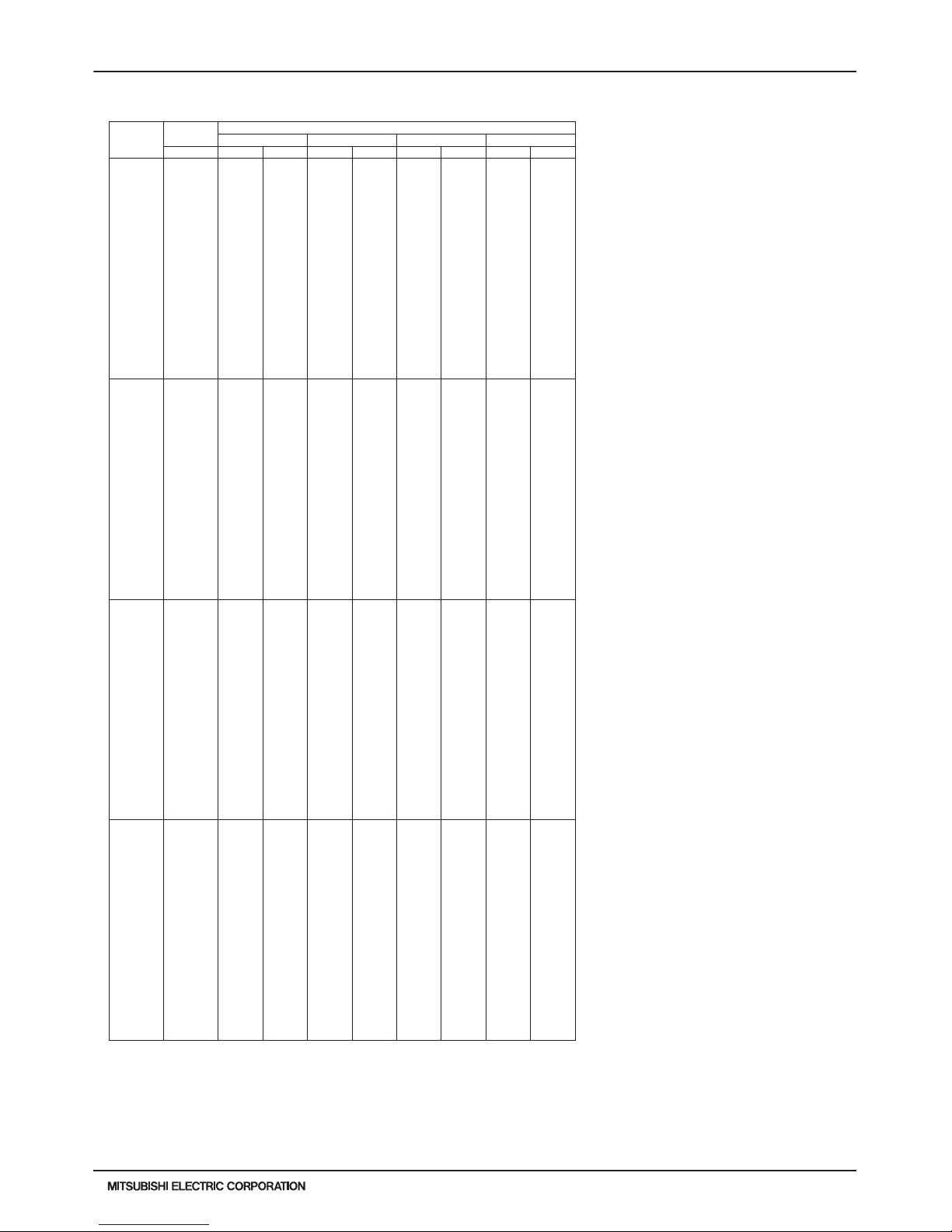
PURY-HP-T(S)KMU,-Y(S)KMU (September 2014)
H2i-R2-87
© 2014 Mitsubishi Electric US, Inc.
7. CAPACITY TABLES
7-4-14. Heating Capacity with PURY-HP96YKMU-A
6. CAPACITY TABLES
DATA U10
PURY-HP96YKMU-A TC:Total Capacity(BTU), PI:Power Input(BTU)
Combination Outdoor Indoor air temp.
(%) air temp. 59°F D.B. 70°F D.B. 77°F D.B. 81°F D.B.
°F W.B. TC PI TC PI TC PI TC PI
150 -13.0 89800 52400 89700 53800 89900 53400 78000 45700
-9.0 95600 52800 95800 54100 91000 51400 78000 43300
-4.0 102900 53300 103000 54700 91000 47800 78000 40300
1.0 110000 53900 108300 54600 91000 44400 78000 3 7400
5.0 115500 54400 108300 51700 91000 41900 78000 3 5300
10.0 122300 55000 108300 48100 91000 38900 78000 327 00
14.0 123400 52800 108300 45400 91000 36600 78000 308 00
19.0 123400 48900 108300 42000 91000 33900 78000 284 00
23.0 123400 45900 108300 39400 91000 31800 78000 267 00
28.0 123400 42300 108300 36200 91000 29400 78000 247 00
32.0 123400 39600 108300 33800 91000 27600 78000 232 00
37.0 123400 36400 108300 30800 91000 25500 78000 214 00
41.0 123400 34000 108300 28500 91000 24000 78000 201 00
43.0 123400 32800 108300 27900 91000 23300 78000 195 00
46.0 123400 31100 108300 26600 91000 22200 78000 186 00
50.0 123400 29000 108300 25200 91000 21000 78000 175 00
55.0 128400 29400 108300 23800 91000 19500 78000 163 00
59.0 134300 29500 108300 23100 91000 18500 78000 154 00
140 -13.0 89900 53000 898 00 54400 8 9900 54000 7 8000 46300
-9.0 95700 53400 95800 54700 91000 52000 78000 43800
-4.0 103000 53900 103000 55400 91000 48400 78000 40700
1.0 110100 54500 108300 55200 91000 45000 78000 3 7800
5.0 115600 55000 108300 52300 91000 42400 78000 3 5700
10.0 122400 55700 108300 48700 91000 39300 78000 331 00
14.0 123500 53500 108300 45900 91000 37000 78000 311 00
19.0 123500 49400 108300 42500 91000 34300 78000 288 00
23.0 123500 46400 108300 39900 91000 32200 78000 270 00
28.0 123500 42800 108300 36700 91000 29800 78000 250 00
32.0 123500 40100 108300 34200 91000 28000 78000 234 00
37.0 123500 36800 108300 31100 91000 25800 78000 216 00
41.0 123500 34400 108300 28800 91000 24300 78000 203 00
43.0 123500 33200 108300 28200 91000 23600 78000 197 00
46.0 123500 31500 108300 26900 91000 22500 78000 188 00
50.0 123500 29300 108300 25500 91000 21200 78000 177 00
55.0 128500 29800 108300 24100 91000 19700 78000 164 00
59.0 134300 29900 108300 23400 91000 18700 78000 156 00
130 -13.0 89900 53800 898 00 55200 8 9900 54800 7 8000 46900
-9.0 95700 54200 95800 55500 91000 527 00 78000 444 00
-4.0 103000 54700 103100 56200 91000 49100 78000 41300
1.0 110100 55300 108300 56000 91000 45600 78000 38400
5.0 115600 55800 108300 53000 91000 43000 78000 36200
10.0 122400 56500 108300 49400 91000 39900 78000 335 00
14.0 123500 54200 108300 46600 91000 37600 78000 316 00
19.0 123500 50100 108300 43100 91000 34800 78000 292 00
23.0 123500 47100 108300 40500 91000 32700 78000 274 00
28.0 123500 43400 108300 37200 91000 30200 78000 253 00
32.0 123500 40600 108300 34700 91000 28400 78000 238 00
37.0 123500 37300 108300 31600 91000 26200 78000 220 00
41.0 123500 34800 108300 29200 91000 24700 78000 206 00
43.0 123500 33700 108300 28600 91000 23900 78000 200 00
46.0 123500 31900 108300 27300 91000 22800 78000 191 00
50.0 123500 29700 108300 25900 91000 21500 78000 180 00
55.0 128500 30200 108300 24500 91000 20000 78000 167 00
59.0 134400 30300 108300 23700 91000 19000 78000 158 00
120 -13.0 89900 54700 898 00 56200 8 9900 55700 7 8000 47700
-9.0 95700 55100 95800 56400 91000 53600 78000 45200
-4.0 103000 55600 103000 57100 91000 49900 78000 42000
1.0 110100 56300 108300 56900 91000 46400 78000 3 9000
5.0 115600 56800 108300 54000 91000 43800 78000 3 6800
10.0 122400 57500 108300 50200 91000 40600 78000 341 00
14.0 123500 55100 108300 47400 91000 38200 78000 321 00
19.0 123500 51000 108300 43900 91000 35300 78000 297 00
23.0 123500 47900 108300 41200 91000 33200 78000 279 00
28.0 123500 44100 108300 37800 91000 30700 78000 258 00
32.0 123500 41300 108300 35300 91000 28900 78000 242 00
37.0 123500 37900 108300 32100 91000 26700 78000 223 00
41.0 123500 35400 108300 29700 91000 25100 78000 210 00
43.0 123500 34200 108300 29100 91000 24300 78000 203 00
46.0 123500 32400 108300 27800 91000 23200 78000 194 00
50.0 123500 30200 108300 26300 91000 21900 78000 183 00
55.0 128500 30700 108300 24900 91000 20300 78000 170 00
59.0 134300 30800 108300 24100 91000 19300 78000 160 00
kcal/h=kW x 860 , BTU/h = kW x 3,412
Page 88

H2i-R2-88
PURY-HP-T(S)KMU,-Y(S)KMU (September 2014)
© 2014 Mitsubishi Electric US, Inc.
7. CAPACITY TABLES
7-4-14. Heating Capacity with PURY-HP96YKMU-A (cont.)
6. CAPACITY TABLES
DATA U10
H2i R2
110 -13.0 89800 55800 89700 57200 89900 56800 78000 48700
-9.0 95600 56200 95800 57500 91000 54700 78000 46000
-4.0 102900 56700 103000 58200 91000 50900 78000 42800
1.0 110000 57300 108300 58100 91000 47300 78000 39800
5.0 115500 57900 108300 55000 91000 44600 78000 37500
10.0 122300 58600 108300 51200 91000 41400 78000 34800
14.0 123400 56200 108300 48300 91000 38900 78000 32700
19.0 123400 52000 108300 44700 91000 36000 78000 30300
23.0 123400 48800 108300 42000 91000 33900 78000 28400
28.0 123400 45000 108300 38600 91000 31300 78000 26300
32.0 123400 42100 108300 36000 91000 29400 78000 24700
37.0 123400 38700 108300 32700 91000 27200 78000 22800
41.0 123400 36100 108300 30300 91000 25600 78000 21400
43.0 123400 34900 108300 29700 91000 24800 78000 20700
46.0 123400 33100 108300 28300 91000 23700 78000 19800
50.0 123400 30800 108300 26800 91000 22300 78000 18600
55.0 128400 31300 108300 25400 91000 20700 78000 17300
59.0 134300 31400 108300 24600 91000 19700 78000 16400
100 -13.0 89700 57000 89700 58500 89800 58000 77900 49700
-9.0 95600 57400 95700 58800 90900 55800 77900 47000
-4.0 102800 58000 102900 59500 90900 52000 77900 4380 0
1.0 109900 58600 108000 59300 90900 48300 77900 40700
5.0 115400 59100 108000 56200 90900 45600 77900 38300
10.0 122200 59800 108000 52300 9090 0 42300 7790 0 35500
14.0 123300 57400 108000 49400 9090 0 39800 7790 0 33400
19.0 123300 53100 108000 45700 9090 0 36800 7790 0 30900
23.0 123300 49900 108000 42900 9090 0 34600 7790 0 29100
28.0 123300 46000 108000 39400 9090 0 32000 7790 0 26800
32.0 123300 43000 108000 36700 9090 0 30100 7790 0 25200
37.0 123300 39500 108000 33500 9090 0 27800 7790 0 23300
41.0 123300 36900 108000 31000 9090 0 26100 7790 0 21800
43.0 123300 35700 108000 30300 9090 0 25300 7790 0 21200
46.0 123300 33800 108000 28900 9090 0 24200 7790 0 20200
50.0 123300 31500 108000 27400 9090 0 22800 7790 0 19000
55.0 128300 32000 108000 25900 9090 0 21200 7790 0 17700
59.0 134200 32100 108000 25100 9090 0 20100 7790 0 16700
90 -13.0 80800 49300 80700 50600 80800 50200 70100 43000
-9.0 86000 49700 86100 50900 81800 48300 70100 40700
-4.0 92600 50200 92600 51500 81800 45000 70100 37900
1.0 99000 50700 97400 51300 81800 41800 70100 35200
5.0 103900 51200 97400 48 600 81800 39400 70100 33200
10.0 110000 51800 97400 45300 81800 36600 70100 30700
14.0 111000 49700 97400 42700 81800 34400 70100 28900
19.0 111000 46000 97400 39500 81800 31900 70100 26800
23.0 111000 43200 97400 37100 81800 30000 70100 25100
28.0 111000 39800 97400 34100 81800 27700 70100 23200
32.0 111000 37200 97400 31800 81800 26000 70100 21800
37.0 111000 34200 97400 29000 81800 24000 70100 20100
41.0 111000 31900 97400 26800 81800 22600 70100 18900
43.0 111000 30900 97400 26200 81800 21900 70100 18300
46.0 111000 29200 97400 25000 81800 20900 70100 17500
50.0 111000 27300 97400 23700 81800 19700 70100 16500
55.0 115500 27700 97400 22400 81800 18300 70100 15300
59.0 120800 27800 97400 21700 81800 17400 70100 14500
80 -13.0 71800 42300 71800 43400 71900 43100 62300 36900
-9.0 76500 42600 76600 43700 72700 41500 62300 34900
-4.0 82300 43000 82300 44200 72700 38600 62300 32500
1.0 88000 43500 86600 44000 72700 35900 62300 30200
5.0 92300 43900 86600 41700 72700 33800 62300 28500
10.0 97800 44400 86600 38900 72700 31400 62300 26400
14.0 98700 42700 86600 36700 72700 29600 62300 24800
19.0 98700 39400 86600 33900 72700 27300 62300 23000
23.0 98700 37000 86600 31800 72700 25700 62300 21600
28.0 98700 34100 86600 29300 72700 23800 62300 19900
32.0 98700 32000 86600 27300 72700 22300 62300 18700
37.0 98700 29300 86600 24800 72700 20600 62300 17300
41.0 98700 27400 86600 23000 72700 19400 62300 16200
43.0 98700 26500 86600 22500 72700 18800 62300 15700
46.0 98700 25100 86600 21500 72700 18000 62300 15000
50.0 98700 23400 86600 20400 72700 16900 62300 14100
55.0 102700 23800 86600 1930 0 72700 15 700 62300 13100
59.0 107400 23900 86600 1860 0 72700 14 900 62300 12400
PURY-HP96YKMU-A TC:Total Capacity(BTU), PI:Power Input(BTU)
Combination Outdoor Indoor air temp.
(%) air temp. 59°F D.B. 70°F D.B. 77°F D.B. 81°F D.B.
°F W.B. TC PI TC PI TC PI TC PI
kcal/h=kW x 860 , BTU/h = kW x 3,412
Page 89

PURY-HP-T(S)KMU,-Y(S)KMU (September 2014)
H2i-R2-89
© 2014 Mitsubishi Electric US, Inc.
7. CAPACITY TABLES
7-4-14. Heating Capacity with PURY-HP96YKMU-A (cont.)
6. CAPACITY TABLES
DATA U10
70 -13.0 62800 36000 62800 37000 62900 36700 54500 31400
-9.0 66900 36300 67000 37200 63600 35300 54500 29700
-4.0 72000 36600 72000 37600 63600 32900 54500 27700
1.0 77000 37000 75800 37500 63600 30500 54500 25700
5.0 80800 37400 75800 35500 63600 28800 54500 24200
10.0 85600 37800 7 5800 33100 63600 26700 54500 22500
14.0 86400 36300 7 5800 31200 63600 25100 54500 21100
19.0 86400 33600 7 5800 28900 63600 23300 54500 19500
23.0 86400 31500 7 5800 27100 63600 21900 54500 18400
28.0 86400 29000 7 5800 24900 63600 20200 54500 17000
32.0 86400 27200 7 5800 23200 63600 19000 54500 15900
37.0 86400 25000 7 5800 21100 63600 17600 54500 14700
41.0 86400 23300 7 5800 19600 63600 16500 54500 13800
43.0 86400 22500 7 5800 19100 63600 16000 54500 13400
46.0 86400 21400 7 5800 18300 63600 15300 54500 12800
50.0 86400 19900 7 5800 17300 63600 14400 54500 12000
55.0 89900 20200 7 5800 16400 63600 13400 54500 11200
59.0 93900 20300 7 5800 15900 63600 12700 54500 10600
60 -13.0 53900 30400 53800 31200 53900 30900 46700 26500
-9.0 57300 30600 57400 31400 54500 29800 46700 25100
-4.0 61700 30900 61800 31700 54500 27700 46700 23300
1.0 66000 31200 64900 31600 54500 25800 46700 21700
5.0 69300 31500 64900 30000 54500 24300 46700 20400
10.0 73300 31900 6 4900 27900 54500 22500 46700 19000
14.0 74000 30600 6 4900 26300 54500 21200 46700 17800
19.0 74000 28300 6 4900 24400 54500 19600 46700 16500
23.0 74000 26600 6 4900 22900 54500 18500 46700 15500
28.0 74000 24500 6 4900 21000 54500 17100 46700 14300
32.0 74000 23000 6 4900 19600 54500 16000 46700 13400
37.0 74000 21100 6 4900 17800 54500 14800 46700 12400
41.0 74000 19700 6 4900 16500 54500 13900 46700 11700
43.0 74000 19000 6 4900 16200 54500 13500 46700 11300
46.0 74000 18000 6 4900 15400 54500 12900 46700 10800
50.0 74000 16800 6 4900 14600 54500 12200 46700 10100
55.0 77000 17100 6 4900 13800 54500 11300 46700 9400
59.0 80500 17100 6 4900 13400 54500 10700 46700 8900
50 -13.0 44900 25400 44800 26100 44900 25900 39000 22200
-9.0 47800 25600 47800 26300 45400 24900 39000 21000
-4.0 51400 25900 51500 26600 45400 23200 39000 19500
1.0 55000 26200 54100 26500 45400 21600 39000 18200
5.0 57700 26400 54100 25100 45400 20400 39000 17100
10.0 61100 26700 5 4100 23400 45400 18900 39000 15900
14.0 61700 25700 5 4100 22000 45400 17800 39000 14900
19.0 61700 23700 5 4100 20400 45400 16400 39000 13800
23.0 61700 22300 5 4100 19200 45400 15500 39000 13000
28.0 61700 20500 5 4100 17600 45400 14300 39000 12000
32.0 61700 19200 5 4100 16400 45400 13400 39000 11300
37.0 61700 17700 5 4100 14900 45400 12400 39000 10400
41.0 61700 16500 5 4100 13800 45400 11700 39000 9800
43.0 61700 15900 5 4100 13500 45400 11300 39000 9500
46.0 61700 15100 5 4100 12900 45400 10800 39000 9000
50.0 61700 14100 5 4100 12200 45400 10200 39000 8500
55.0 64200 14300 5 4100 11600 45400 950 0 39000 7900
59.0 67100 14300 5 4100 11200 45400 900 0 39000 7500
PURY-HP96YKMU-A TC:Total Capacity(BTU), PI:Power Input(BTU)
Combination Outdoor Indoor air temp.
(%) air temp. 59°F D.B. 70°F D.B. 77°F D.B. 81°F D.B.
°F W.B. TC PI TC PI TC PI TC PI
kcal/h=kW x 860 , BTU/h = kW x 3,412
Page 90

H2i-R2-90
PURY-HP-T(S)KMU,-Y(S)KMU (September 2014)
© 2014 Mitsubishi Electric US, Inc.
7. CAPACITY TABLES
7-4-15. Heating Capacity with PURY-HP144YSKMU-A
6. CAPACITY TABLES
DATA U10
PURY-HP144YSKMU-A TC:Total Capacity(BTU), PI:Power Input(BTU)
Combination Outdoor Indoor air temp.
(%) air temp. 59°F D.B. 70°F D.B. 77°F D.B. 81°F D.B.
°F W.B. TC PI TC PI TC PI TC PI
150 -13.0 134100 75600 134000 77600 134100 77000 116400 66000
-9.0 142800 76200 142900 78000 135800 74100 116400 62400
-4.0 153600 76900 153700 79000 135800 69000 116400 58100
1.0 164200 77800 161600 78700 135800 64100 116400 54000
5.0 172400 78500 161600 74600 135800 60500 116400 50900
10.0 182600 79400 161600 69400 135800 56100 116400 47200
14.0 184200 76200 161600 65500 135800 52800 116400 44400
19.0 184200 70500 161600 60600 135800 48900 116400 41000
23.0 184200 66200 161600 56900 135800 45900 116400 38600
28.0 184200 61000 161600 52300 135800 42400 116400 35600
32.0 184200 57100 161600 48800 135800 39900 116400 33400
37.0 184200 52400 161600 44400 135800 36900 116400 30900
41.0 184200 49000 161600 41100 135800 34700 116400 29000
43.0 184200 47300 161600 40200 135800 33600 116400 28100
46.0 184200 44800 161600 38400 135800 32100 116400 26800
50.0 184200 41800 161600 36400 135800 30200 116400 25200
55.0 191700 42400 161600 34400 135800 28100 116400 23400
59.0 200400 42600 161600 33300 135800 26600 116400 22200
140 -13.0 133800 76700 133700 78700 133900 78100 116200 66900
-9.0 142500 77200 142700 79100 135600 75100 116200 63300
-4.0 153400 78000 153500 80100 135600 70000 116200 58900
1.0 164000 78800 161400 79800 135600 65000 116200 54700
5.0 172100 79600 161400 75600 135600 61300 116200 51600
10.0 182300 80500 161400 70400 135600 56900 116200 47800
14.0 184000 77300 161400 66400 135600 53500 116200 45000
19.0 184000 71500 161400 61500 135600 49500 116200 41600
23.0 184000 67100 161400 57700 135600 46600 116200 39100
28.0 184000 61800 161400 53000 135600 43000 116200 36100
32.0 184000 57900 161400 49400 135600 40400 116200 33900
37.0 184000 53200 161400 45000 135600 37400 116200 31300
41.0 184000 49700 161400 41700 135600 35100 116200 29400
43.0 184000 48000 161400 40800 135600 34100 116200 28500
46.0 184000 45500 161400 38900 135600 32500 116200 27200
50.0 184000 42400 161400 36900 135600 30700 116200 25600
55.0 191400 43000 161400 34900 135600 28500 116200 23800
59.0 200100 43200 161400 33800 135600 27000 116200 22500
130 -13.0 133600 78100 133500 80200 133700 79500 116000 68100
-9.0 142300 78600 142500 80600 135300 76500 116000 64500
-4.0 153100 79400 153200 81500 135300 71200 116000 60000
1.0 163700 80300 161100 81300 135300 66200 116000 55700
5.0 171800 81000 161100 77000 135300 62500 116000 52500
10.0 182000 82000 161100 71700 135300 57900 116000 48700
14.0 183600 78700 161100 67600 135300 54500 116000 45800
19.0 183600 72800 161100 62600 135300 50500 116000 42400
23.0 183600 68400 161100 58800 135300 47400 116000 39800
28.0 183600 63000 161100 54000 135300 43800 116000 36800
32.0 183600 59000 161100 50400 135300 41200 116000 34500
37.0 183600 54200 161100 45900 135300 38100 116000 31900
41.0 183600 50600 161100 42400 135300 35800 116000 29900
43.0 183600 48900 161100 41500 135300 34700 116000 29000
46.0 183600 46300 161100 39600 135300 33100 116000 27700
50.0 183600 43200 161100 37600 135300 31200 116000 26100
55.0 191100 43800 161100 35500 135300 29000 116000 24200
59.0 199700 44000 161100 34400 135300 27500 116000 22900
120 -13.0 133300 79800 133200 82000 133400 81300 115700 69700
-9.0 142000 80400 142200 82400 135000 78300 115700 65900
-4.0 152800 81200 152900 83400 135000 72800 115700 61300
1.0 163300 82100 160800 83100 135000 67700 115700 57000
5.0 171500 82900 160800 78700 135000 63900 115700 53700
10.0 181600 83900 160800 73300 135000 59200 115700 49800
14.0 183300 80500 160800 69200 135000 55800 115700 46900
19.0 183300 74400 160800 64000 135000 51600 115700 43300
23.0 183300 69900 160800 60100 135000 48500 115700 40700
28.0 183300 64400 160800 55200 135000 44800 115700 37600
32.0 183300 60300 160800 51500 135000 42100 115700 35300
37.0 183300 55400 160800 46900 135000 38900 115700 32600
41.0 183300 51700 160800 43400 135000 36600 115700 30600
43.0 183300 50000 160800 42500 135000 35500 115700 29700
46.0 183300 47400 160800 40500 135000 33900 115700 28300
50.0 183300 44200 160800 38400 135000 31900 115700 26700
55.0 190700 44800 160800 36300 135000 29700 115700 24800
59.0 199300 45000 160800 35200 135000 28100 115700 23400
kcal/h=kW x 860 , BTU/h = kW x 3,412
Page 91

PURY-HP-T(S)KMU,-Y(S)KMU (September 2014)
H2i-R2-91
© 2014 Mitsubishi Electric US, Inc.
7. CAPACITY TABLES
7-4-15. Heating Capacity with PURY-HP144YSKMU-A (cont.)
6. CAPACITY TABLES
DATA U10
H2i R2
110 -13.0 133000 82 000 132900 84100 13 3100 83500 115500 71 500
-9.0 141700 82600 141800 84600 134700 80300 115500 67700
-4.0 152400 83400 152600 85600 134700 74800 115500 63000
1.0 163000 84300 160400 85300 134700 69500 115500 58500
5.0 171100 85000 160400 80800 134700 65600 115500 55200
10.0 181200 86100 160400 75300 134700 60800 115500 51100
14.0 182900 82600 160400 71000 134700 57200 115500 48100
19.0 182900 76400 160400 65700 134700 53000 115500 44500
23.0 182900 71800 160400 61700 134700 49800 115500 41800
28.0 182900 66100 160400 56700 134700 46000 115500 38600
32.0 182900 61900 160400 52900 134700 43200 115500 36200
37.0 182900 56800 160400 48100 134700 40000 115500 33500
41.0 182900 53100 160400 44500 134700 37600 115500 31400
43.0 182900 51300 160400 43600 134700 36400 115500 30500
46.0 182900 48600 160400 41600 134700 34800 115500 29100
50.0 182900 45300 160400 39400 134700 32800 115500 27400
55.0 190300 46000 160400 37300 134700 30500 115500 25400
59.0 198900 46200 160400 36100 134700 28900 115500 24000
100 -13.0 132700 84400 132600 86700 132800 86000 115200 73700
-9.0 141300 85000 141500 87100 134400 82700 115200 69700
-4.0 152100 85900 152200 88200 134400 77000 115200 64900
1.0 162600 86800 160000 87900 134400 71600 115200 60300
5.0 170700 87600 160000 83300 134400 67500 115200 56800
10.0 180800 88700 160000 77500 134400 62600 115200 52700
14.0 182400 85100 160000 73100 134400 59000 115200 49600
19.0 182400 78700 160000 67700 134400 54600 115200 45800
23.0 182400 73900 160000 63500 134400 51300 115200 43100
28.0 182400 68100 160000 58400 134400 47400 115200 39800
32.0 182400 63800 160000 54400 134400 44500 115200 37300
37.0 182400 58600 160000 49600 134400 41200 115200 34500
41.0 182400 54700 160000 45900 134400 38700 115200 32400
43.0 182400 52800 160000 44900 134400 37500 115200 31400
46.0 182400 50100 160000 42900 134400 35800 115200 29900
50.0 182400 46700 160000 40600 134400 33800 115200 28200
55.0 189800 47400 160000 38400 134400 31400 115200 26200
59.0 198400 47600 160000 37200 134400 29800 115200 24800
90 -13.0 119400 74400 119400 76400 119500 75800 103700 64900
-9.0 127200 75000 127400 76800 121000 73000 103700 61400
-4.0 136900 75700 137000 77700 121000 67900 103700 57200
1.0 146300 76500 144000 77500 121000 63100 103700 53100
5.0 153600 77200 144000 73400 121000 59500 103700 50100
10.0 162700 78200 144000 68400 121000 55200 103700 46400
14.0 164200 75000 144000 64500 121000 52000 103700 43700
19.0 164200 69400 144000 59700 121000 48100 103700 40400
23.0 164200 65200 144000 56000 121000 45200 103700 38000
28.0 164200 60000 144000 51500 121000 41800 103700 35100
32.0 164200 56200 144000 48000 121000 39300 103700 32900
37.0 164200 51600 144000 43700 121000 36300 103700 30400
41.0 164200 48200 144000 40400 121000 34100 103700 28500
43.0 164200 46600 144000 39600 121000 33100 103700 27700
46.0 164200 44200 144000 37800 121000 31600 103700 26400
50.0 164200 41200 144000 35800 121000 29800 103700 24900
55.0 170800 41800 144000 33900 121000 27700 103700 23100
59.0 178600 42000 144000 32800 121000 26200 103700 21800
80 -13.0 106200 65200 106100 66900 106200 66400 92200 56900
-9.0 113100 65600 113200 67200 107500 63900 92200 53800
-4.0 121700 66300 121800 68100 107500 59500 92200 50100
1.0 130100 67000 128000 67800 107500 55300 92200 46500
5.0 136500 67600 128000 64300 107500 52100 92200 43900
10.0 144600 68500 128000 59900 107 500 48300 92200 40600
14.0 145900 65700 128000 56500 107 500 45500 92200 38300
19.0 145900 60800 128000 52300 107 500 42100 92200 35400
23.0 145900 57100 128000 49000 107 500 39600 92200 33200
28.0 145900 52600 128000 45100 107 500 36600 92200 30700
32.0 145900 49200 128000 42000 107 500 34400 92200 28800
37.0 145900 45200 128000 38300 107 500 31800 92200 26600
41.0 145900 42200 128000 35400 107 500 29900 92200 25000
43.0 145900 40800 128000 34700 107 500 29000 92200 24200
46.0 145900 38700 128000 33100 107 500 27700 92200 23100
50.0 145900 36000 128000 31400 107 500 26100 92200 21800
55.0 151800 36600 128000 29700 107 500 24200 92200 20200
59.0 158700 36700 128000 28700 107 500 23000 92200 19100
PURY-HP144YSKMU-A TC:Total Capacity(BTU), PI:Power Input(BTU)
Combination Outdoor Indoor air temp.
(%) air temp. 59°F D.B. 70°F D.B. 77°F D.B. 81°F D.B.
°F W.B. TC PI TC PI TC PI TC PI
kcal/h=kW x 860 , BTU/h = kW x 3,412
Page 92

H2i-R2-92
PURY-HP-T(S)KMU,-Y(S)KMU (September 2014)
© 2014 Mitsubishi Electric US, Inc.
7. CAPACITY TABLES
7-4-15. Heating Capacity with PURY-HP144YSKMU-A (cont.)
6. CAPACITY TABLES
DATA U10
70 -13.0 92900 56600 92800 58100 93000 57700 80700 49400
-9.0 98900 57000 99100 58400 94100 55500 80700 46700
-4.0 106500 57600 106500 59100 94100 51700 80700 43500
1.0 113800 58200 112000 59000 94100 48000 80700 40400
5.0 119500 58800 112000 55900 94100 45300 80700 38100
10.0 126500 59500 112000 52000 94100 42000 80700 35300
14.0 127700 57100 112000 49100 94100 39600 80700 33200
19.0 127700 52800 112000 45400 94100 36600 80700 30700
23.0 127700 49600 112000 42600 94100 34400 80700 28900
28.0 127700 45700 112000 39200 94100 31800 80700 26700
32.0 127700 42800 112000 36500 94100 29900 80700 25000
37.0 127700 39300 112000 33300 94100 27600 80700 23100
41.0 127700 36700 112000 30800 94100 26000 80700 21700
43.0 127700 35400 112000 30100 94100 25200 80700 21100
46.0 127700 33600 112000 28800 94100 24000 80700 20100
50.0 127700 31300 112000 27200 94100 22700 80700 18900
55.0 132900 31800 112000 25800 94100 21100 80700 17600
59.0 138900 31900 112000 24900 94100 20000 80700 16600
60 -13.0 79600 48800 79600 50100 79700 49700 69100 42600
-9.0 84800 49200 84900 50400 80700 47800 69100 40300
-4.0 91300 49700 91300 51000 80700 44500 69100 37500
1.0 97600 50200 96000 50800 80700 41400 69100 34800
5.0 102400 50700 96000 48200 80700 39100 69100 32900
10.0 108500 51300 96000 44800 80700 36200 69100 30400
14.0 109500 49200 96000 42300 80700 34100 69100 28700
19.0 109500 45500 96000 39100 80700 31500 69100 26500
23.0 109500 42700 96000 36700 80700 29700 69100 24900
28.0 109500 39400 96000 33800 80700 27400 69100 23000
32.0 109500 36900 96000 31500 80700 25800 69100 21600
37.0 109500 33900 96000 28700 80700 23800 69100 19900
41.0 109500 31600 96000 26500 80700 22400 69100 18700
43.0 109500 30600 96000 26000 80700 21700 69100 18200
46.0 109500 29000 96000 24800 80700 20700 69100 17300
50.0 109500 27000 96000 23500 80700 19500 69100 16300
55.0 113900 27400 96000 22200 80700 18200 69100 15100
59.0 119100 27500 96000 21500 80700 17200 69100 14300
50 -13.0 66400 41700 66300 42800 66400 42500 57600 36400
-9.0 70700 42000 70800 43100 67200 40900 57600 34500
-4.0 76100 42500 76100 43600 67200 38100 57600 32100
1.0 81300 42900 80000 43400 67200 35400 57600 29800
5.0 85400 43300 80000 41200 67200 33400 57600 28100
10.0 90400 43800 80000 38300 67200 31000 57600 26000
14.0 91200 42100 80000 36200 67200 29100 57600 24500
19.0 91200 38900 80000 33500 67200 27000 57600 22700
23.0 91200 36500 80000 31400 67200 25400 57600 21300
28.0 91200 33700 80000 28900 67200 23400 57600 19700
32.0 91200 31500 80000 26900 67200 22000 57600 18500
37.0 91200 28900 80000 24500 67200 20300 57600 17000
41.0 91200 27000 80000 22700 67200 19100 57600 16000
43.0 91200 26100 80000 22200 67200 18600 57600 15500
46.0 91200 24800 80000 21200 67200 17700 57600 14800
50.0 91200 23100 80000 20100 67200 16700 57600 13900
55.0 94900 23400 80000 19000 67200 15500 57600 12900
59.0 99200 23500 80000 18400 67200 14700 57600 12200
PURY-HP144YSKMU-A TC:Total Capacity(BTU), PI:Power Input(BTU)
Combination Outdoor Indoor air temp.
(%) air temp. 59°F D.B. 70°F D.B. 77°F D.B. 81°F D.B.
°F W.B. TC PI TC PI TC PI TC PI
kcal/h=kW x 860 , BTU/h = kW x 3,412
Page 93

PURY-HP-T(S)KMU,-Y(S)KMU (September 2014)
H2i-R2-93
© 2014 Mitsubishi Electric US, Inc.
7. CAPACITY TABLES
7-4-16. Heating Capacity with PURY-HP192YSKMU-A
6. CAPACITY TABLES
DATA U10
PURY-HP192YSKMU-A TC:Total Capacity(BTU), PI:Power Input(BTU)
Combination Outdoor Indoor air temp.
(%) air temp. 59°F D.B. 70°F D.B. 77°F D.B. 81°F D.B.
°F W.B. TC PI TC PI TC PI TC PI
150 -13.0 178500 109300 178300 112200 178600 111300 154900 95400
-9.0 190000 110100 190300 112800 180700 107100 154900 90200
-4.0 204500 111200 204600 114200 180700 99700 154900 84000
1.0 218600 112400 215200 113800 180700 92700 154900 7 8000
5.0 229500 113400 215200 107800 180700 87500 154900 7 3600
10.0 243100 114800 215200 100400 180700 81100 154900 68200
14.0 245300 110200 215200 94700 1 80700 76300 154900 64200
19.0 245300 101900 215200 87700 1 80700 70600 154900 59300
23.0 245300 95700 215200 82300 180700 66400 154900 55800
28.0 245300 88200 215200 75600 180700 61400 154900 51500
32.0 245300 82600 215200 70500 180700 57700 154900 48300
37.0 245300 75800 215200 64200 180700 53300 154900 44600
41.0 245300 70800 215200 59400 180700 50100 154900 41900
43.0 245300 68400 215200 58100 180700 48600 154900 40600
46.0 245300 64800 215200 55500 180700 46400 154900 38800
50.0 245300 60500 215200 52600 180700 43700 154900 36500
55.0 255200 61400 215200 49700 180700 40700 154900 33900
59.0 266800 61600 215200 48200 180700 38500 154900 32100
140 -13.0 178500 110600 178400 113500 178700 112600 155000 96500
-9.0 190100 111400 190400 114100 180800 108400 155000 91300
-4.0 204600 112500 204700 115500 180800 100900 155000 85000
1.0 218700 113700 215300 115100 180800 93800 155000 7 8900
5.0 229600 114800 215300 109100 180800 88500 155000 7 4400
10.0 243200 116200 215300 101600 180800 82000 155000 69000
14.0 245400 111500 215300 95800 180800 77200 155000 64900
19.0 245400 103100 215300 88700 180800 71500 155000 60000
23.0 245400 96800 215300 83200 180800 67200 155000 56400
28.0 245400 89200 215300 76500 180800 62100 155000 52100
32.0 245400 83500 215300 71300 180800 58300 155000 48900
37.0 245400 76700 215300 64900 180800 53900 155000 45100
41.0 245400 71700 215300 60100 180800 50700 155000 42400
43.0 245400 69200 215300 58800 180800 49200 155000 41100
46.0 245400 65600 215300 56100 180800 46900 155000 39200
50.0 245400 61200 215300 53200 180800 44200 155000 36900
55.0 255300 62100 215300 50300 180800 41100 155000 34300
59.0 266900 62300 215300 48700 180800 39000 155000 32500
130 -13.0 178600 112200 178400 115200 178700 114300 155000 97900
-9.0 190200 113000 190400 115800 180800 110000 155000 92600
-4.0 204600 114100 204800 117200 180800 102400 155000 86200
1.0 218800 115400 215300 116800 180800 95100 155000 80100
5.0 229600 116400 215300 110700 180800 89700 155000 75500
10.0 243200 117800 215300 103000 180800 83200 155000 70000
14.0 245400 113100 215300 97200 1 80800 78300 155000 65800
19.0 245400 104600 215300 90000 1 80800 72500 155000 60900
23.0 245400 98200 215300 84400 180800 68200 155000 57200
28.0 245400 90500 215300 77600 180800 63000 155000 52800
32.0 245400 84700 215300 72300 180800 59200 155000 49600
37.0 245400 77800 215300 65900 180800 54700 155000 45800
41.0 245400 72700 215300 61000 180800 51400 155000 43000
43.0 245400 70200 215300 59700 180800 49900 155000 41700
46.0 245400 66500 215300 57000 180800 47600 155000 39800
50.0 245400 62000 215300 54000 180800 44900 155000 37500
55.0 255400 63000 215300 51100 180800 41700 155000 34800
59.0 267000 63200 215300 49400 180800 39500 155000 32900
120 -13.0 178500 114100 178400 117100 178700 116200 155000 99500
-9.0 190100 114900 190400 117700 180800 111800 155000 94200
-4.0 204600 116100 204700 119200 180800 104100 155000 87600
1.0 218700 117300 215300 118800 180800 96800 155000 8 1400
5.0 229600 118400 215300 112500 180800 91300 155000 7 6800
10.0 243200 119800 215300 104800 180800 84600 155000 71200
14.0 245400 115000 215300 98800 180800 79700 155000 67000
19.0 245400 106400 215300 91500 180800 73700 155000 61900
23.0 245400 99900 215300 85900 180800 69300 155000 58200
28.0 245400 92000 215300 78900 180800 64100 155000 53700
32.0 245400 86200 215300 73600 180800 60200 155000 50500
37.0 245400 79100 215300 67000 180800 55600 155000 46600
41.0 245400 73900 215300 62000 180800 52300 155000 43800
43.0 245400 71400 215300 60700 180800 50700 155000 42400
46.0 245400 67700 215300 57900 180800 48400 155000 40500
50.0 245400 63100 215300 54900 180800 45600 155000 38100
55.0 255300 64000 215300 51900 180800 42400 155000 35400
59.0 266900 64300 215300 50300 180800 40200 155000 33500
kcal/h=kW x 860 , BTU/h = kW x 3,412
Page 94

H2i-R2-94
PURY-HP-T(S)KMU,-Y(S)KMU (September 2014)
© 2014 Mitsubishi Electric US, Inc.
7. CAPACITY TABLES
7-4-16. Heating Capacity with PURY-HP192YSKMU-A (cont.)
6. CAPACITY TABLES
DATA U10
H2i R2
110 -13.0 178500 116300 178300 119400 178600 118500 154900 101500
-9.0 190000 117100 190300 120000 180700 114000 154900 96000
-4.0 204500 118300 204600 121500 180700 106100 154900 89300
1.0 218600 119600 215200 121100 180700 98600 154900 83000
5.0 229500 120700 215200 114700 180700 93000 154900 78300
10.0 243100 122200 215200 106800 180700 86300 154900 72500
14.0 245300 117300 215200 100800 180700 81200 154900 68300
19.0 245300 108400 215200 93 300 180700 75200 154 900 63100
23.0 245300 101800 215200 87 500 180700 70700 154 900 59300
28.0 245300 93800 215200 80400 180700 65300 154900 54800
32.0 245300 87900 215200 75000 180700 61400 154900 51400
37.0 245300 80700 215200 68300 180700 56700 154900 47500
41.0 245300 75400 215200 63200 180700 53300 154900 44600
43.0 245300 72800 215200 61900 180700 51700 154900 43200
46.0 245300 69000 215200 59000 180700 49400 154900 41200
50.0 245300 64300 215200 56000 180700 46500 154900 38800
55.0 255200 65300 215200 52900 180700 43300 154900 36100
59.0 266800 65600 215200 51200 180700 41000 154900 34100
100 -13.0 178300 118800 178200 122000 178500 121000 154800 103700
-9.0 189900 119700 190100 122600 180600 116500 154800 98100
-4.0 204300 120900 204500 124100 180600 108400 154800 91300
1.0 218500 122200 215000 123700 180600 100800 154800 84800
5.0 229300 123300 215000 117200 180600 95100 154800 80000
10.0 242900 124800 215000 109100 180600 88200 154800 74100
14.0 245100 119800 215000 103000 180600 83000 154800 69800
19.0 245100 110800 215000 95300 180600 76800 154800 64500
23.0 245100 104000 215000 89400 180600 72200 154800 60600
28.0 245100 95900 215000 82200 180600 66700 154800 56000
32.0 245100 89800 215000 76600 180600 62700 154800 52600
37.0 245100 82400 215000 69800 180600 57900 154800 48500
41.0 245100 77000 215000 64600 180600 54500 154800 45600
43.0 245100 74400 215000 63200 180600 52800 154800 44200
46.0 245100 70500 215000 60300 180600 50400 154800 42100
50.0 245100 65700 215000 57200 180600 47500 154800 39700
55.0 255000 66700 215000 54100 180600 44200 154800 36900
59.0 266600 67000 215000 52400 180600 41900 154800 34900
90 -13.0 160500 102800 160400 105600 160600 104700 139300 89700
-9.0 170900 103600 171100 106100 162600 100800 139300 84900
-4.0 183900 104600 184100 107400 162600 93800 139300 79000
1.0 196600 105800 193500 107100 162600 87200 139300 73400
5.0 206400 106700 193500 101400 162600 82300 139300 69200
10.0 218600 108000 193500 94400 162600 76300 139300 64100
14.0 220600 103700 193500 89100 162600 71800 139300 60400
19.0 220600 95900 193500 82500 162600 66500 139300 55800
23.0 220600 90000 193500 77400 162600 62500 139300 52400
28.0 220600 83000 193500 71100 162600 57700 139300 48400
32.0 220600 77700 193500 66300 162600 54300 139300 45500
37.0 220600 71300 193500 60400 162600 50100 139300 42000
41.0 220600 66600 193500 55900 162600 47100 139300 39400
43.0 220600 64400 193500 54700 162600 45700 139300 38200
46.0 220600 61000 193500 52200 162600 43600 139300 36500
50.0 220600 56900 193500 49500 162600 41100 139300 34300
55.0 229500 57700 193500 46800 162600 38300 139300 31900
59.0 240000 58000 193500 45300 162600 36200 139300 30200
80 -13.0 142700 88200 142600 90600 142800 89900 123900 77000
-9.0 151900 88900 152100 91100 144500 86500 123900 72900
-4.0 163500 89800 163600 92200 144500 80500 123900 67800
1.0 174800 90800 172000 91900 144500 74900 123900 63000
5.0 183500 91600 172000 87000 144500 70600 123900 59400
10.0 194300 92700 172000 81100 144500 65500 123900 55000
14.0 196100 89000 172000 76500 144500 61600 123900 51800
19.0 196100 82300 172000 70800 144500 57000 123900 47900
23.0 196100 77300 172000 66400 144500 53600 123900 45000
28.0 196100 71200 172000 61000 144500 49600 123900 41600
32.0 196100 66700 172000 56900 144500 46600 123900 39000
37.0 196100 61200 172000 51800 144500 43000 123900 36000
41.0 196100 57200 172000 48000 144500 40500 123900 33800
43.0 196100 55200 172000 46900 144500 39200 123900 32800
46.0 196100 52400 172000 44800 144500 37500 123900 31300
50.0 196100 48800 172000 42500 144500 35300 123900 29500
55.0 204000 49500 172000 40200 144500 32800 123900 27400
59.0 213300 49800 172000 38900 144500 31100 123900 25900
PURY-HP192YSKMU-A TC:Total Capacity(BTU), PI:Power Input(BTU)
Combination Outdoor Indoor air temp.
(%) air temp. 59°F D.B. 70°F D.B. 77°F D.B. 81°F D.B.
°F W.B. TC PI TC PI TC PI TC PI
kcal/h=kW x 860 , BTU/h = kW x 3,412
Page 95

PURY-HP-T(S)KMU,-Y(S)KMU (September 2014)
H2i-R2-95
© 2014 Mitsubishi Electric US, Inc.
7. CAPACITY TABLES
7-4-16. Heating Capacity with PURY-HP192YSKMU-A (cont.)
6. CAPACITY TABLES
DATA U10
70 -13.0 124800 75100 124800 77100 124900 76500 108400 65500
-9.0 132900 75600 133100 77500 126400 73600 108400 62000
-4.0 143100 76400 143200 78400 126400 68500 108400 57700
1.0 152900 77200 150500 78200 126400 63700 108400 53600
5.0 160600 77900 150500 74100 126400 60100 108400 50500
10.0 170000 78900 150500 69000 126400 55700 108400 46800
14.0 171600 75700 150500 65100 126400 52500 108400 44100
19.0 171600 70000 150500 60200 126400 48500 108400 40800
23.0 171600 65800 150500 56500 126400 45600 108400 38300
28.0 171600 60600 150500 51900 126400 42200 108400 35400
32.0 171600 56700 150500 48400 126400 39600 108400 33200
37.0 171600 52100 150500 44100 126400 36600 108400 30700
41.0 171600 48700 150500 40800 126400 34400 108400 28800
43.0 171600 47000 150500 39900 126400 33400 108400 27900
46.0 171600 44600 150500 38100 126400 31900 108400 26600
50.0 171600 41500 150500 36100 126400 30000 108400 25100
55.0 178500 42200 150500 34200 126400 27900 108400 23300
59.0 186700 42300 150500 33100 126400 26500 108400 22000
60 -13.0 107000 63400 106900 65100 107100 64500 92900 55300
-9.0 114000 63800 114100 65400 108400 62100 92900 5 2300
-4.0 122600 64500 122700 66200 108400 57800 92900 4 8700
1.0 131100 65200 129000 66000 10 8400 53800 92900 45200
5.0 137600 65800 129000 62500 10 8400 50700 92900 42700
10.0 145700 66600 129000 58200 1084 00 47000 9 2900 39500
14.0 147100 63900 129000 54900 1084 00 44300 9 2900 37200
19.0 147100 59100 129000 50800 1084 00 41000 9 2900 34400
23.0 147100 55500 129000 47700 1084 00 38500 9 2900 32300
28.0 147100 51100 129000 43800 1084 00 35600 9 2900 29800
32.0 147100 47900 129000 40900 1084 00 33400 9 2900 28000
37.0 147100 44000 129000 37200 1084 00 30900 9 2900 25900
41.0 147100 41100 129000 34400 1084 00 29000 9 2900 24300
43.0 147100 39700 129000 33700 1084 00 28200 9 2900 23600
46.0 147100 37600 129000 32200 1084 00 26900 9 2900 22500
50.0 147100 35000 129000 30500 1084 00 25300 9 2900 21200
55.0 153000 35600 129000 28800 1084 00 23600 9 2900 19700
59.0 160000 35700 129000 27900 1084 00 22300 9 2900 18600
50 -13.0 89200 53100 89100 54500 89200 54100 77400 46300
-9.0 94900 53500 95100 54800 90300 52000 77400 43800
-4.0 102200 54000 102200 55400 90300 48400 77400 40800
1.0 109200 54600 107500 55300 90300 45000 77400 37900
5.0 114700 55100 107500 52400 90300 42500 77400 35700
10.0 121400 55800 107500 48700 90300 39400 77400 33100
14.0 122500 53500 107500 46000 90300 37100 77400 31200
19.0 122500 49500 107500 42600 90300 34300 77400 28800
23.0 122500 46500 107500 39900 90300 32200 77400 27100
28.0 122500 42800 107500 36700 90300 29800 77400 25000
32.0 122500 40100 107500 34200 90300 28000 77400 23500
37.0 122500 36800 107500 31200 90300 25900 77400 21700
41.0 122500 34400 107500 28800 90300 24300 77400 20400
43.0 122500 33200 107500 28200 90300 23600 77400 19700
46.0 122500 31500 107500 26900 90300 22500 77400 18800
50.0 122500 29400 107500 25500 90300 21200 77400 17700
55.0 127500 29800 107500 24200 90300 19700 77400 16500
59.0 133300 29900 107500 23400 90300 18700 77400 15600
PURY-HP192YSKMU-A TC:Total Capacity(BTU), PI:Power Input(BTU)
Combination Outdoor Indoor air temp.
(%) air temp. 59°F D.B. 70°F D.B. 77°F D.B. 81°F D.B.
°F W.B. TC PI TC PI TC PI TC PI
kcal/h=kW x 860 , BTU/h = kW x 3,412
Page 96
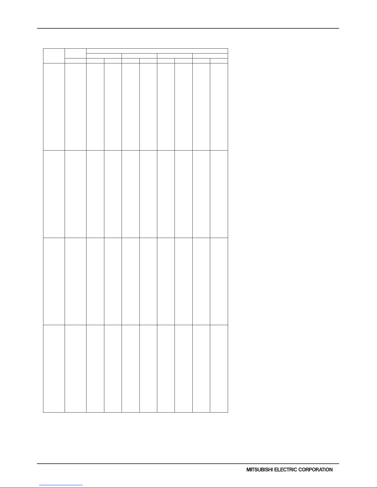
H2i-R2-96
PURY-HP-T(S)KMU,-Y(S)KMU (September 2014)
© 2014 Mitsubishi Electric US, Inc.
7. CAPACITY TABLES
7-4-17. Heating Capacity [High Heat Performance Mode] with PURY-HP72TKMU-A-H
6. CAPACITY TABLES
DATA U10
PURY-HP72TKMU-A-H TC:Total Capacity(BTU), PI:Power Input(BTU)
Combination Outdoor Indoor air temp.
(%) air temp. 59°F D.B. 70°F D.B. 77°F D.B. 81°F D.B.
°F W.B. TC PI TC PI TC PI TC PI
150 -13.0 66800 36000 66800 37000 66800 37100 66900 37600
-9.0 71300 36300 71400 37200 71500 37700 70800 37600
-4.0 76700 36700 76700 37700 76300 38300 68800 34300
1.0 82000 37100 81600 38200 764 00 35700 668 00 31100
5.0 85900 37400 85100 38700 749 00 33300 652 00 28700
10.0 90800 37700 85100 35600 72900 30200 63200 25700
14.0 94400 37900 83700 33000 71300 27800 61600 23500
19.0 94000 34900 82000 29800 69300 24800 59600 20700
23.0 91900 32000 80600 27400 67700 22500 58000 18600
28.0 91900 28900 80600 24600 67700 20200 58000 16700
32.0 91900 27000 80600 22800 67700 18700 58000 15500
37.0 91900 24800 80600 20900 67700 17100 58000 14300
41.0 91900 23200 80600 19700 67700 16000 58000 13400
43.0 91900 22500 80600 19200 67700 15500 58000 13000
46.0 91900 21400 80600 18300 67700 14900 58000 12500
50.0 91900 20100 80600 17300 67700 14200 58000 11900
55.0 95600 20200 80600 16400 67700 13600 58000 11400
59.0 100000 20300 80600 15900 67700 13300 58000 11100
140 -13.0 66700 36500 66700 37500 66700 37600 66800 38100
-9.0 71200 36800 713 00 37800 7 1400 38200 70700 38100
-4.0 76600 37200 766 00 38200 7 6100 38900 68700 34800
1.0 81900 37600 81500 38700 76200 36200 66700 31600
5.0 85800 37900 84900 39200 74700 33800 65100 29100
10.0 90600 38200 85000 36100 72800 30700 63100 26100
14.0 94300 38500 83600 33500 71200 28200 61500 23800
19.0 93900 35400 81900 30300 69200 25200 59500 21000
23.0 91800 32500 80500 27800 67600 22800 57900 18800
28.0 91800 29300 80500 25000 67600 20400 57900 16900
32.0 91800 27400 80500 23100 67600 18900 57900 15700
37.0 91800 25200 80500 21200 67600 17300 57900 14500
41.0 91800 23500 80500 19900 67600 16200 57900 13600
43.0 91800 22800 80500 19400 67600 15700 57900 13200
46.0 91800 21700 80500 18600 67600 15100 57900 12700
50.0 91800 20400 80500 17600 67600 14400 57900 12100
55.0 95500 20500 80500 16600 67600 13800 57900 11600
59.0 99800 20600 80500 16100 67600 13500 57900 11300
130 -13.0 66600 37200 66600 38200 66600 38300 66700 38800
-9.0 71000 37500 71200 38500 71300 38900 70600 38800
-4.0 76500 37900 76500 38900 76000 39600 68600 35400
1.0 81700 38300 81300 39400 76100 36900 66600 32100
5.0 85600 38600 84800 39900 74600 34400 65000 29700
10.0 90500 38900 84800 36700 72700 31200 63000 26600
14.0 94100 39200 83500 34100 71100 28800 61400 24200
19.0 93700 36000 81700 30800 69100 25600 59400 21400
23.0 91600 33100 80300 28300 67400 23200 57800 19200
28.0 91600 29900 80300 25400 67500 20800 57800 17200
32.0 91600 27900 80300 23500 67500 19300 57800 16000
37.0 91600 25600 80300 21500 67500 17600 57800 14700
41.0 91600 24000 80300 20300 67500 16500 57800 13800
43.0 91600 23200 80300 19800 67500 16000 57800 13400
46.0 91600 22100 80300 18900 67500 15400 57800 12900
50.0 91600 20800 80300 17900 67500 14700 57800 12300
55.0 95300 20900 80300 16900 67500 14000 57800 11800
59.0 99600 21000 80300 16400 67500 13800 57800 11500
120 -13.0 66500 38000 66500 39000 66500 39200 66500 39700
-9.0 70900 38400 710 00 39300 7 1200 39800 70400 39700
-4.0 76300 38800 763 00 39800 7 5900 40500 68400 36200
1.0 81500 39200 81200 40300 759 00 37700 664 00 32900
5.0 85500 39500 84600 40800 745 00 35200 649 00 30300
10.0 90300 39800 8 4700 37600 72500 31900 62900 27200
14.0 93900 40100 8 3300 34900 71000 29400 61300 24800
19.0 93500 36900 8 1600 31500 68900 26200 59300 21800
23.0 91400 33800 8 0200 28900 67300 23700 57700 19600
28.0 91400 30600 8 0200 26000 67300 21300 57700 17600
32.0 91400 28500 8 0200 24100 67300 19700 57700 16400
37.0 91400 26200 8 0200 22000 67300 18000 57700 15100
41.0 91400 24500 8 0200 20800 67300 16900 57700 14200
43.0 91400 23700 8 0200 20200 67300 16400 57700 13800
46.0 91400 22600 8 0200 19300 67300 15700 57700 13200
50.0 91400 21200 8 0200 18300 67300 15000 57700 12600
55.0 95100 21400 8 0200 17300 67300 14400 57700 12000
59.0 99400 21500 8 0200 16800 67300 14100 57700 11700
kcal/h=kW x 860 , BTU/h = kW x 3,412
Page 97
PURY-HP-T(S)KMU,-Y(S)KMU (September 2014)
H2i-R2-97
© 2014 Mitsubishi Electric US, Inc.
7. CAPACITY TABLES
7-4-17. Heating Capacity [High Heat Performance Mode] with PURY-HP72TKMU-A-H (cont.)
6. CAPACITY TABLES
DATA U10
H2i R2
110 -13.0 66300 39000 66300 40100 66300 40200 66400 40700
-9.0 70700 39400 70900 40400 71000 40800 70300 40700
-4.0 76200 39800 76200 40800 75700 41500 68300 37200
1.0 81400 40200 81000 41400 75800 38700 66300 33700
5.0 85300 40500 84400 41900 74300 36100 64700 31100
10.0 90100 40900 84500 38600 72300 32800 62700 27900
14.0 93700 41100 83100 35800 70800 30200 61200 25400
19.0 93300 37800 81400 32400 68800 26900 59200 22400
23.0 91200 34700 80000 29700 67200 24400 57600 20100
28.0 91200 31400 80000 26700 67200 21900 57600 18100
32.0 91200 29300 80000 24700 67200 20300 57600 16800
37.0 91200 26900 80000 22600 67200 18500 57600 15500
41.0 91200 25200 80000 21300 67200 17300 57600 14500
43.0 91200 24400 80000 20800 67200 16800 57600 14100
46.0 91200 23200 80000 19800 67200 16100 57600 13500
50.0 91200 21800 80000 18800 67200 15400 57600 12900
55.0 94900 21900 80000 17800 67200 14700 57600 12400
59.0 99200 22000 80000 17200 67200 14400 57600 12100
100 -13.0 66200 40200 66200 41300 66100 41400 66200 41900
-9.0 70600 40600 70700 41600 70800 42100 70100 42000
-4.0 76000 41000 76000 42100 75500 42800 68100 38300
1.0 81200 41400 80800 42600 75600 39900 66100 34800
5.0 85100 41700 84200 43200 74100 37200 64500 32100
10.0 89900 42100 84300 39700 72200 33800 62600 28700
14.0 93500 42400 82900 36900 70600 31100 61000 26200
19.0 93100 39000 81200 33300 68600 27700 59000 23100
23.0 91000 35800 80000 30600 67000 25100 57500 20700
28.0 91000 32300 80000 27500 67000 22500 57500 18600
32.0 91000 30200 80000 25400 67000 20900 57500 17300
37.0 91000 27700 80000 23300 67000 19100 57500 15900
41.0 91000 25900 80000 22000 67000 17900 57500 15000
43.0 91000 25100 80000 21400 67000 17300 57500 14500
46.0 91000 23900 80000 20400 67000 16600 57500 14000
50.0 91000 22500 80000 19400 67000 15900 57500 13300
55.0 94700 22600 80000 18300 67000 15200 57500 12700
59.0 99000 22700 80000 17700 67000 14900 57500 12400
90 -13.0 59500 35400 59600 36400 59500 36500 59600 37000
-9.0 63500 35800 63600 36700 63700 37100 63100 37000
-4.0 68400 36100 68400 37100 68000 37700 61300 33800
1.0 73000 36500 72700 37600 68000 35200 59500 30700
5.0 76600 36800 75800 38100 66700 32800 58100 28300
10.0 80900 37100 75800 35000 65000 29800 56300 25300
14.0 84100 37400 74600 32500 63600 27400 54900 23100
19.0 83800 34400 73100 29400 61700 24400 53100 20400
23.0 81900 31600 71800 26900 60300 22100 51700 18300
28.0 81900 28500 71800 24200 60300 19800 51700 16400
32.0 81900 26600 71800 22400 60300 18400 51700 15300
37.0 81900 24400 71800 20500 60300 16800 51700 14000
41.0 81900 22900 71800 19400 60300 15700 51700 13200
43.0 81900 22100 71800 18900 60300 15300 51700 12800
46.0 81900 21100 71800 18000 60300 14600 51700 12300
50.0 81900 19800 71800 17100 60300 14000 51700 11800
55.0 85200 19900 71800 16100 60300 13400 51700 11200
59.0 89100 20000 71800 15600 60300 13100 51700 11000
80 -13.0 52900 31000 52900 31900 52900 32000 53000 32400
-9.0 56500 31300 56500 32100 56700 32500 56100 32400
-4.0 60800 31600 60800 32500 60400 33000 54500 29600
1.0 64900 32000 64600 32900 60500 30800 52900 26800
5.0 68100 32200 67400 33300 59300 28700 51600 24800
10.0 71900 32500 67400 30700 57700 26100 50100 22200
14.0 74800 32700 66300 28500 56500 24000 48800 20200
19.0 74500 30100 64900 25700 54900 21400 47200 17800
23.0 72800 27600 63800 23600 53600 19400 46000 16000
28.0 72800 24900 63800 21200 53600 17400 46000 14400
32.0 72800 23300 63800 19600 53600 16100 46000 13400
37.0 72800 21400 63800 18000 53600 14700 46000 12300
41.0 72800 20000 63800 17000 53600 13800 46000 11600
43.0 72800 19400 63800 16500 53600 13400 46000 11200
46.0 72800 18400 63800 15800 53600 12800 46000 10800
50.0 72800 17300 63800 14900 53600 12200 46000 10300
55.0 75700 17400 63800 14100 53600 11700 46000 9800
59.0 79200 17500 63800 13700 53600 11500 46000 9600
PURY-HP72TKMU-A-H TC:Total Capacity(BTU), PI:Power Input(BTU)
Combination Outdoor Indoor air temp.
(%) air temp. 59°F D.B. 70°F D.B. 77°F D.B. 81°F D.B.
°F W.B. TC PI TC PI TC PI TC PI
kcal/h=kW x 860 , BTU/h = kW x 3,412
Page 98

H2i-R2-98
PURY-HP-T(S)KMU,-Y(S)KMU (September 2014)
© 2014 Mitsubishi Electric US, Inc.
7. CAPACITY TABLES
7-4-17. Heating Capacity [High Heat Performance Mode] with PURY-HP72TKMU-A-H (cont.)
6. CAPACITY TABLES
DATA U10
70 -13.0 46300 27000 46300 27700 46300 27800 46400 28100
-9.0 49400 27200 49500 27900 49600 28200 49100 28200
-4.0 53200 27500 53200 28200 52900 28700 47700 25700
1.0 56800 27800 56600 28600 52900 26800 46300 23300
5.0 59600 28000 59000 29000 51900 24900 45200 21500
10.0 62900 28200 5 9000 26600 50500 22700 43800 19300
14.0 65400 28400 5 8000 24700 49400 20900 42700 17600
19.0 65200 26100 5 6800 22400 48000 18600 41300 15500
23.0 63700 24000 5 5900 20500 46900 16800 40200 13900
28.0 63700 21700 5 5900 18400 46900 15100 40200 12500
32.0 63700 20200 5 5900 17100 46900 14000 40200 11600
37.0 63700 18600 5 5900 15600 46900 12800 40200 10700
41.0 63700 17400 5 5900 14700 46900 12000 40200 10000
43.0 63700 16800 5 5900 14400 46900 11600 40200 9800
46.0 63700 16000 5 5900 13700 46900 11100 40200 9400
50.0 63700 15100 5 5900 13000 46900 10600 40200 8900
55.0 66300 15200 5 5900 12300 46900 10200 40200 8500
59.0 69300 15200 5 5900 11900 46900 10000 40200 8300
60 -13.0 39700 23200 39700 23900 39700 23900 39800 24300
-9.0 42300 23500 42400 24000 42500 24300 42100 24300
-4.0 45600 23700 45600 24300 45300 24700 40900 22200
1.0 48700 23900 48500 24700 45400 23100 39700 20100
5.0 51100 24100 50500 25000 44500 21500 38700 18500
10.0 53900 24300 5 0600 23000 43300 19500 37500 16600
14.0 56100 24500 4 9800 21300 42400 18000 36600 15200
19.0 55900 22500 4 8700 19300 41200 16000 35400 13400
23.0 54600 20700 4 7900 17700 40200 14500 34500 12000
28.0 54600 18700 4 7900 15900 40200 13000 34500 10800
32.0 54600 17500 4 7900 14700 40200 12100 34500 10000
37.0 54600 16000 4 7900 13500 40200 11000 34500 9200
41.0 54600 15000 4 7900 12700 40200 10300 34500 8700
43.0 54600 14500 4 7900 12400 40200 10000 34500 8400
46.0 54600 13800 4 7900 11800 40200 960 0 34500 8100
50.0 54600 13000 4 7900 11200 40200 920 0 34500 7700
55.0 56800 13100 4 7900 10600 40200 880 0 34500 7400
59.0 59400 13100 4 7900 10300 40200 860 0 34500 7200
50 -13.0 33100 19900 33100 20400 33100 20500 33100 20700
-9.0 35300 20000 35400 20600 35400 20800 35100 20700
-4.0 38000 20300 38000 20800 37800 21200 34100 18900
1.0 40600 20500 40400 21100 37800 19700 33100 17200
5.0 42600 20600 42100 21300 37100 18400 32300 15900
10.0 44900 20800 4 2100 19600 36100 16700 31300 14200
14.0 46700 20900 4 1500 18200 35300 15400 30500 13000
19.0 46600 19300 4 0600 16500 34300 13700 29500 11400
23.0 45500 17700 3 9900 15100 33500 12400 28700 10300
28.0 45500 16000 3 9900 13600 33500 11100 28700 9200
32.0 45500 14900 3 9900 12600 33500 10300 28700 8600
37.0 45500 13700 3 9900 11500 33500 940 0 28700 7900
41.0 45500 12800 3 9900 10900 33500 880 0 28700 7400
43.0 45500 12400 3 9900 10600 33500 860 0 28700 7200
46.0 45500 11800 3 9900 10100 33500 820 0 28700 6900
50.0 45500 11100 3 9900 9600 33500 7800 28700 6600
55.0 47300 11200 3 9900 9100 33500 7500 28700 6300
59.0 49500 11200 3 9900 8800 33500 7400 28700 6100
PURY-HP72TKMU-A-H TC:Total Capacity(BTU), PI:Power Input(BTU)
Combination Outdoor Indoor air temp.
(%) air temp. 59°F D.B. 70°F D.B. 77°F D.B. 81°F D.B.
°F W.B. TC PI TC PI TC PI TC PI
kcal/h=kW x 860 , BTU/h = kW x 3,412
Page 99
PURY-HP-T(S)KMU,-Y(S)KMU (September 2014)
H2i-R2-99
© 2014 Mitsubishi Electric US, Inc.
7. CAPACITY TABLES
7-4-18. Heating Capacity [High Heat Performance Mode] with PURY-HP96TKMU-A-H
6. CAPACITY TABLES
DATA U10
PURY-HP96TKMU-A-H TC:Total Capacity(BTU), PI:Power Input(BTU)
Combination Outdoor Indoor air temp.
(%) air temp. 59°F D.B. 70°F D.B. 77°F D.B. 81°F D.B.
°F W.B. TC PI TC PI TC PI TC PI
150 -13.0 89800 52400 89800 53700 89800 53900 89900 54600
-9.0 95700 52800 95900 54200 96100 54800 95100 54700
-4.0 103100 53400 103100 54800 102400 55700 92400 4 9900
1.0 110100 53900 109600 55500 102600 52000 89700 45300
5.0 115400 54300 114300 56200 100600 48400 87600 41800
10.0 121900 54800 114300 51700 97900 44000 84900 374 00
14.0 126800 55200 112500 48000 95800 40500 82800 341 00
19.0 126300 50800 110100 43400 93100 36100 80100 301 00
23.0 123400 46600 108300 39800 90900 32700 78000 270 00
28.0 123400 42100 108300 35800 91000 29300 78000 242 00
32.0 123400 39300 108300 33100 91000 27200 78000 226 00
37.0 123400 36100 108300 30300 91000 24800 78000 207 00
41.0 123400 33800 108300 28600 91000 23300 78000 195 00
43.0 123400 32700 108300 27900 91000 22600 78000 189 00
46.0 123400 31100 108300 26600 91000 21600 78000 182 00
50.0 123400 29200 108300 25200 91000 20700 78000 174 00
55.0 128400 29400 108300 23800 91000 19800 78000 166 00
59.0 134300 29500 108300 23100 91000 19400 78000 162 00
140 -13.0 89800 53000 898 00 54400 8 9800 54600 8 9900 55300
-9.0 95800 53400 96000 54800 96100 55400 95100 55300
-4.0 103100 54000 103100 55400 102500 56400 92400 50500
1.0 110200 54600 109700 56200 102600 52600 89700 45800
5.0 115500 55000 114300 56900 100600 49000 87600 42300
10.0 122000 55500 114400 52300 98000 44500 84900 379 00
14.0 126900 55800 112500 48600 95900 41000 82800 345 00
19.0 126400 51400 110200 43900 93100 36500 80100 304 00
23.0 123500 47200 108300 40300 90900 33100 78000 273 00
28.0 123500 42600 108300 36200 91000 29700 78000 245 00
32.0 123500 39800 108300 33500 91000 27500 78000 228 00
37.0 123500 36500 108300 30700 91000 25100 78000 210 00
41.0 123500 34200 108300 28900 91000 23500 78000 197 00
43.0 123500 33100 108300 28200 91000 22800 78000 192 00
46.0 123500 31500 108300 26900 91000 21900 78000 184 00
50.0 123500 29600 108300 25500 91000 20900 78000 176 00
55.0 128500 29800 108300 24100 91000 20000 78000 168 00
59.0 134300 29900 108300 23400 91000 19600 78000 164 00
130 -13.0 89800 53700 898 00 55200 8 9800 55300 8 9900 56100
-9.0 95800 54200 96000 55600 96200 562 00 95200 561 00
-4.0 103200 54800 103200 56200 102500 57200 92500 5 1200
1.0 110200 55300 109700 57000 102600 53300 89800 46500
5.0 115500 55800 114300 57700 100600 49700 87600 42900
10.0 122000 56300 114400 53100 98000 45100 84900 384 00
14.0 126900 56600 112600 49300 95900 41600 82800 350 00
19.0 126400 52100 110200 44600 93200 37100 80100 309 00
23.0 123500 47800 108300 40800 91000 33500 78000 277 00
28.0 123500 43200 108300 36700 91000 30100 78000 249 00
32.0 123500 40300 108300 34000 91000 27900 78000 232 00
37.0 123500 37000 108300 31100 91000 25500 78000 213 00
41.0 123500 34600 108300 29400 91000 23900 78000 200 00
43.0 123500 33500 108300 28600 91000 23200 78000 194 00
46.0 123500 31900 108300 27300 91000 22200 78000 187 00
50.0 123500 30000 108300 25900 91000 21200 78000 178 00
55.0 128500 30200 108300 24500 91000 20300 78000 170 00
59.0 134400 30300 108300 23700 91000 19900 78000 166 00
120 -13.0 89800 54600 898 00 56100 8 9800 56300 8 9900 57000
-9.0 95800 55100 96000 56500 96100 57200 95100 57000
-4.0 103100 55700 103100 57200 102500 58200 92400 5 2100
1.0 110200 56300 109700 58000 102600 54200 89700 47300
5.0 115500 56700 114300 58700 100600 50600 87600 43600
10.0 122000 57200 114400 54000 98000 45900 84900 391 00
14.0 126900 57600 112500 50100 95900 42300 82800 356 00
19.0 126400 53000 110200 45300 93100 37700 80100 314 00
23.0 123500 48600 108300 41500 90900 34100 78000 282 00
28.0 123500 43900 108300 37400 91000 30600 78000 253 00
32.0 123500 41000 108300 34600 91000 28400 78000 236 00
37.0 123500 37600 108300 31700 91000 25900 78000 216 00
41.0 123500 35200 108300 29900 91000 24300 78000 203 00
43.0 123500 34100 108300 29100 91000 23600 78000 198 00
46.0 123500 32500 108300 27800 91000 22600 78000 190 00
50.0 123500 30500 108300 26300 91000 21600 78000 181 00
55.0 128500 30700 108300 24900 91000 20600 78000 173 00
59.0 134300 30800 108300 24100 91000 20200 78000 169 00
kcal/h=kW x 860 , BTU/h = kW x 3,412
Page 100

H2i-R2-100
PURY-HP-T(S)KMU,-Y(S)KMU (September 2014)
© 2014 Mitsubishi Electric US, Inc.
7. CAPACITY TABLES
7-4-18. Heating Capacity [High Heat Performance Mode] with PURY-HP96TKMU-A-H (cont.)
6. CAPACITY TABLES
DATA U10
H2i R2
110 -13.0 89800 55700 89800 57200 89800 57400 89900 58100
-9.0 95700 56200 95900 57600 96100 58300 95100 58200
-4.0 103100 56800 103100 58300 102400 59300 92400 53100
1.0 110100 57400 109600 59100 102600 55300 89700 48200
5.0 115400 57800 114300 59800 100600 51500 87600 44400
10.0 121900 58300 114300 55000 97900 46800 84900 39800
14.0 126800 58700 112500 51100 95800 43100 82800 36300
19.0 126300 54000 110100 46200 93100 38400 80100 32000
23.0 123400 49600 108300 42400 90900 34800 78000 28700
28.0 123400 44800 108300 38100 91000 31200 78000 25800
32.0 123400 41800 108300 35300 91000 28900 78000 24000
37.0 123400 38400 108300 32300 91000 26400 78000 22100
41.0 123400 35900 108300 30400 91000 24700 78000 20700
43.0 123400 34800 108300 29700 91000 24000 78000 20200
46.0 123400 33100 108300 28300 91000 23000 78000 19300
50.0 123400 31100 108300 26800 91000 22000 78000 18500
55.0 128400 31300 108300 25400 91000 21000 78000 17600
59.0 134300 31400 108300 24600 91000 20600 78000 17200
100 -13.0 89700 56900 89700 58400 89700 58600 89800 59400
-9.0 95700 57400 95800 58900 96000 59600 95000 59400
-4.0 103000 58000 103000 59600 102400 60600 92300 54200
1.0 110000 58600 109500 60400 102500 56500 89600 49200
5.0 115400 59100 114200 61100 100500 52700 87500 45400
10.0 121800 59600 114300 56200 9790 0 47800 8480 0 40700
14.0 126700 60000 112400 52200 9580 0 44000 8270 0 37100
19.0 126200 55200 110100 47200 9300 0 39300 8000 0 32700
23.0 123300 50700 108000 43300 9080 0 35500 7790 0 29400
28.0 123300 45800 108000 38900 9090 0 31900 7790 0 26400
32.0 123300 42700 108000 36000 9090 0 29500 7790 0 24600
37.0 123300 39200 108000 33000 9090 0 27000 7790 0 22500
41.0 123300 36700 108000 31100 9090 0 25300 7790 0 21200
43.0 123300 35500 108000 30300 9090 0 24500 7790 0 20600
46.0 123300 33800 108000 28900 9090 0 23500 7790 0 19800
50.0 123300 31800 108000 27400 9090 0 22400 7790 0 18900
55.0 128300 32000 108000 25900 9090 0 21500 7790 0 18000
59.0 134200 32100 108000 25100 9090 0 21100 7790 0 17600
90 -13.0 80700 49300 80800 50600 80700 50700 80800 51400
-9.0 86100 49700 86300 51000 86400 51500 85500 51400
-4.0 92700 50200 92700 51500 92100 52400 83100 46900
1.0 99000 50700 98600 52300 92300 48900 80700 42600
5.0 103800 51100 102800 52900 90400 45600 78800 39300
10.0 109700 51600 102800 48700 8810 0 41400 7640 0 35200
14.0 114100 51900 101200 45200 8620 0 38100 7440 0 32100
19.0 113600 47800 99100 4080 0 83700 34 000 72000 28300
23.0 111000 43800 97400 3740 0 81800 30 700 70100 25400
28.0 111000 39600 97400 3370 0 81800 27 600 70100 22800
32.0 111000 37000 97400 3120 0 81800 25 600 70100 21200
37.0 111000 33900 97400 2850 0 81800 23 300 70100 19500
41.0 111000 31800 97400 2690 0 81800 21 900 70100 18300
43.0 111000 30700 97400 2620 0 81800 21 200 70100 17800
46.0 111000 29300 97400 2500 0 81800 20 400 70100 17100
50.0 111000 27500 97400 2370 0 81800 19 400 70100 16300
55.0 115500 27700 97400 2240 0 81800 18 600 70100 15600
59.0 120800 27800 97400 2170 0 81800 18 200 70100 15200
80 -13.0 71800 42300 71800 43400 71800 43500 71900 44100
-9.0 76600 42600 76700 43700 76800 44200 76000 44100
-4.0 82400 43100 82400 44200 81900 45000 73900 40300
1.0 88000 43500 87600 44800 82000 42000 71700 36600
5.0 92300 43900 91400 45400 80400 39100 70000 33700
10.0 97500 44300 91400 41800 78300 35500 67900 30200
14.0 101400 44600 89900 3880 0 76600 32 700 66200 27600
19.0 101000 41000 88100 3500 0 74400 29 200 64000 24300
23.0 98700 37600 86600 32100 72700 26400 62300 21800
28.0 98700 34000 86600 28900 72700 23700 62300 19600
32.0 98700 31700 86600 26800 72700 21900 62300 18200
37.0 98700 29100 86600 24500 72700 20000 62300 16700
41.0 98700 27300 86600 23100 72700 18800 62300 15700
43.0 98700 26400 86600 22500 72700 18200 62300 15300
46.0 98700 25100 86600 21500 72700 17500 62300 14700
50.0 98700 23600 86600 20400 72700 16700 62300 14000
55.0 102700 23800 86600 1930 0 72700 16 000 62300 13400
59.0 107400 23900 86600 1860 0 72700 15 600 62300 13100
PURY-HP96TKMU-A-H TC:Total Capacity(BTU), PI:Power Input(BTU)
Combination Outdoor Indoor air temp.
(%) air temp. 59°F D.B. 70°F D.B. 77°F D.B. 81°F D.B.
°F W.B. TC PI TC PI TC PI TC PI
kcal/h=kW x 860 , BTU/h = kW x 3,412
 Loading...