

Mitsubishi GX Configurator-TI, Q68TD-G-H02 User Manual

Channel Isolated Thermocouple Input Module
User's Manual
-Q68TD-G-H01
-Q68TD-G-H02
-GX Configurator-TI (SW1D5C-QTIU-E)

SAFETY PRECAUTIONS
(Read these precautions before using this product.)
Before using this product, please read this manual and the relevant manuals carefully and pay full attention
to safety to handle the product correctly.
In this manual, the safety precautions are classified into two levels: " WARNING" and " CAUTION".
WARNING
CAUTION
Under some circumstances, failure to observe the precautions given under " CAUTION" may lead to
serious consequences.
Observe the precautions of both levels because they are important for personal and system safety.
Make sure that the end users read this manual and then keep the manual in a safe place for future
reference.
Indicates that incorrect handling may cause hazardous conditions,
resulting in death or severe injury.
Indicates that incorrect handling may cause hazardous conditions,
resulting in minor or moderate injury or property damage.
[Design Precautions]
WARNING
● Do not write any data to the "system area" of the buffer memory in the intelligent function module.
Also, do not use any "use prohibited" signals as an output signal from the programmable controller
CPU to the intelligent function module.
Doing so may cause malfunction of the programmable controller system.
CAUTION
● Do not install the control lines or communication cables together with the main circuit lines or power
cables.
Keep a distance of 100mm or more between them.
Failure to do so may result in malfunction due to noise.
A - 1
[Installation Precautions]
CAUTION
● Use the programmable controller in an environment that meets the general specifications in the
user's manual for the CPU module used.
Failure to do so may result in electric shock, fire, malfunction, or damage to or deterioration of the
product.
● To mount the module, while pressing the module mounting lever located in the lower part of the
module, fully insert the module fixing projection(s) into the hole(s) in the base unit and press the
module until it snaps into place.
Incorrect mounting may cause malfunction, failure or drop of the module.
Fix the module to the base unit with a fixing bracket. (Q68TD-G-H02 only)
When using the programmable controller in an environment of frequent vibrations, fix the module
with a module fixing screw. (Q68TD-G-H01 only)
● Tighten the screw within the specified torque range.
Undertightening can cause drop of the screw, short circuit or malfunction.
Overtightening can damage the screw and/or module, resulting in drop, short circuit, or malfunction.
● Shut off the external power supply (all phases) used in the system before mounting or removing the
module.
Failure to do so may result in damage to the product.
A module can be replaced online (while power is on) on any MELSECNET/H remote I/O station or in
the system where a CPU module supporting the online module change function is used.
Note that there are restrictions on the modules that can be replaced online, and each module has its
predetermined replacement procedure.
For details, refer to the relevant chapter in this manual.
● Do not directly touch any conductive parts and electronic components of the module.
Doing so can cause malfunction or failure of the module.
[Wiring Precautions]
CAUTION
● Individually ground the shielded cables of the programmable controller with a ground resistance of
or less. Failure to do so may result in electric shock or malfunction.
100
● Connectors for external devices must be crimped or pressed with the tool specified by the
manufacturer, or must be correctly soldered.
Incomplete connections may cause short circuit, fire, or malfunction.
● Prevent foreign matter such as dust or wire chips from entering the module.
Such foreign matter can cause a fire, failure, or malfunction.
A - 2

[Wiring Precautions]
CAUTION
● A protective film is attached to the top of the module to prevent foreign matter, such as wire chips,
from entering the module during wiring.
Do not remove the film during wiring.
Remove it for heat dissipation before system operation.
● Place the cables in a duct or clamp them.
If not, dangling cable may swing or inadvertently be pulled, resulting in damage to the module or
cables or malfunction due to poor contact.
● When disconnecting the cable from the module, do not pull the cable by the cable part.
For the cable with connector, hold the connector part of the cable.
Pulling the cable connected to the module may result in malfunction or damage to the module or
cable.
● Keep a distance of 100mm or more between a thermocouple and the main circuit line or AC control
lines.
Also, keep the thermocouple away from a circuit that includes harmonics, such as a high-voltage
circuit and a load circuit of an inverter.
● Do not place the module near a device that generates magnetic noise.
A - 3
[Startup and Maintenance Precautions]
WARNING
● Do not touch any terminal while power is on.
Doing so will cause electric shock or malfunction.
● Shut off the external power supply (all phases) used in the system before cleaning the module or
retightening the terminal screws, connector screws, or module fixing screws.
Failure to do so may result in electric shock or cause the module to fail or malfunction.
Undertightening can cause drop of the screw, short circuit or malfunction.
Overtightening can damage the screw and/or module, resulting in drop, short circuit, or malfunction.
CAUTION
● Do not disassemble or modify the modules.
Doing so may cause failure, malfunction, injury, or a fire.
● Shut off the external power supply (all phases) used in the system before mounting or removing the
module.
Failure to do so may cause the module to fail or malfunction.
A module can be replaced online (while power is on) on any MELSECNET/H remote I/O station or in
the system where a CPU module supporting the online module change function is used.
Note that there are restrictions on the modules that can be replaced online, and each module has its
predetermined replacement procedure.
For details, refer to the relevant chapter in this manual.
● After the first use of the product, do not mount/remove the module to/from the base unit more than
50 times (IEC 61131-2 compliant).
Exceeding the limit of 50 times may cause malfunction.
● Before handling the module, touch a grounded metal object to discharge the static electricity from
the human body.
Failure to do so may cause the module to fail or malfunction.
[Disposal Precautions]
CAUTION
● When disposing of this product, treat it as industrial waste.
A - 4

CONDITIONS OF USE FOR THE PRODUCT
(1) Mitsubishi programmable controller ("the PRODUCT") shall be used in conditions;
i) where any problem, fault or failure occurring in the PRODUCT, if any, shall not lead to any major
or serious accident; and
ii) where the backup and fail-safe function are systematically or automatically provided outside of
the PRODUCT for the case of any problem, fault or failure occurring in the PRODUCT.
(2) The PRODUCT has been designed and manufactured for the purpose of being used in general
industries.
MITSUBISHI SHALL HAVE NO RESPONSIBILITY OR LIABILITY (INCLUDING, BUT NOT
LIMITED TO ANY AND ALL RESPONSIBILITY OR LIABILITY BASED ON CONTRACT,
WARRANTY, TORT, PRODUCT LIABILITY) FOR ANY INJURY OR DEATH TO PERSONS OR
LOSS OR DAMAGE TO PROPERTY CAUSED BY the PRODUCT THAT ARE OPERATED OR
USED IN APPLICATION NOT INTENDED OR EXCLUDED BY INSTRUCTIONS, PRECAUTIONS,
OR WARNING CONTAINED IN MITSUBISHI'S USER, INSTRUCTION AND/OR SAFETY
MANUALS, TECHNICAL BULLETINS AND GUIDELINES FOR the PRODUCT.
("Prohibited Application")
Prohibited Applications include, but not limited to, the use of the PRODUCT in;
• Nuclear Power Plants and any other power plants operated by Power companies, and/or any
other cases in which the public could be affected if any problem or fault occurs in the PRODUCT.
• Railway companies or Public service purposes, and/or any other cases in which establishment of
a special quality assurance system is required by the Purchaser or End User.
• Aircraft or Aerospace, Medical applications, Train equipment, transport equipment such as
Elevator and Escalator, Incineration and Fuel devices, Vehicles, Manned transportation,
Equipment for Recreation and Amusement, and Safety devices, handling of Nuclear or
Hazardous Materials or Chemicals, Mining and Drilling, and/or other applications where there is a
significant risk of injury to the public or property.
Notwithstanding the above, restrictions Mitsubishi may in its sole discretion, authorize use of the
PRODUCT in one or more of the Prohibited Applications, provided that the usage of the PRODUCT
is limited only for the specific applications agreed to by Mitsubishi and provided further that no
special quality assurance or fail-safe, redundant or other safety features which exceed the general
specifications of the PRODUCTs are required. For details, please contact the Mitsubishi
representative in your region.
A - 5
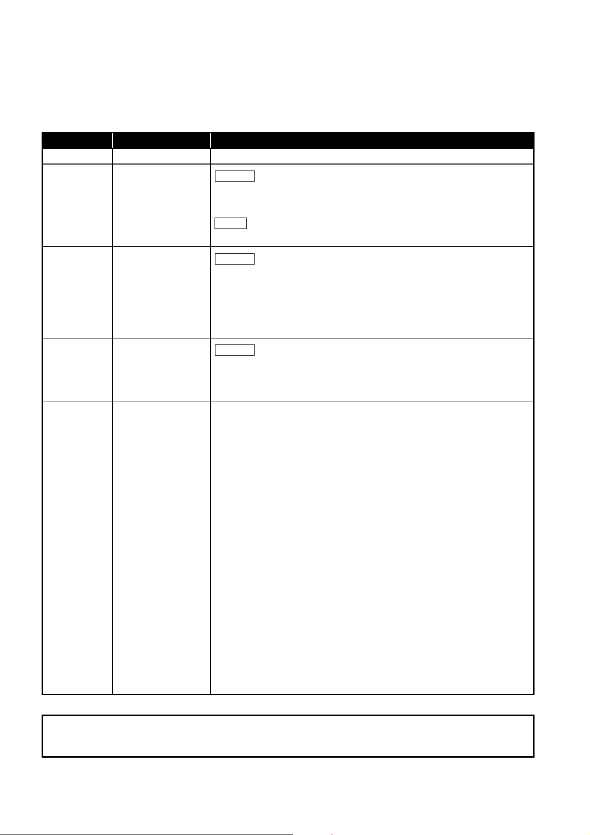
REVISIONS
Correction
Addition
Correction
Correction
*The manual number is given on the bottom left of the back cover.
Print Date *Manual Number Revision
Nov., 2008 SH(NA)-080795ENG-A First printing
Sep., 2011 SH(NA)-080795ENG-B
SAFETY PRECAUTIONS, COMPLIANCE WITH EMC AND LOW VOLTAGE
DIRECTIVES, Section 6.2.3, WARRANTY
CONDITIONS OF USE FOR THE PRODUCT
Feb., 2012 SH(NA)-080795ENG-C
SAFETY PRECAUTIONS, GENERIC TERMS, ABBREVIATIONS, AND TERMS,
Chapter 1, Section 1.1, 2.1 to 2.3, 3.1, 3.2, 3.2.1, 3.2.4, 3.3.1, 3.3.2, 3.4.1, 3.4.4,
3.4.5, 3.4.10, 3.4.11, 4.1, 4.3, 4.4.1, 4.4.2, 4.5 to 4.7, 5.2.1, 5.2.2, 5.3.1, 5.4, 5.5,
5.6.1, 5.6.2, 6.2.1, 6.2.2, 6.3.2, 7.1, 7.2, 7.3.1 to 7.3.6, 7.4.1, 7.4.2, 7.5, 8.1,
8.2.9, Appendix 2.2 to 2.4, Appendix 3
Jun., 2016 SH(NA)-080795ENG-D
COMPLIANCE WITH EMC AND LOW VOLTAGE DIRECTIVES,
GENERIC TERMS, ABBREVIATIONS, AND TERMS, Section 2.1, 2.2, 2.3, 3.1,
3.2.1, 4.4.2, 5.2.2, 6.2, 6.2.2, 6.2.3, 6.3, 6.3.2, 6.3.3, 8.1, 8.2.1, 8.2.9
Japanese Manual Version SH-080794-F
This manual confers no industrial property rights or any rights of any other kind, nor does it confer any patent licenses.
Mitsubishi Electric Corporation cannot be held responsible for any problems involving industrial property rights which may
occur as a result of using the contents noted in this manual.
© 2008 MITSUBISHI ELECTRIC CORPORATION
A - 6

INTRODUCTION
Thank you for purchasing the MELSEC-Q series Programmable Controller.
Before using the equipment, please read this manual carefully to develop full familiarity with the functions
and performance of the Q series Programmable Controller you have purchased, so as to ensure correct
use.
Please forward a copy of this manual to the end user.
CONTENTS
SAFETY PRECAUTIONS .................................................................................................................................A - 1
CONDITIONS OF USE FOR THE PRODUCT..................................................................................................A - 5
REVISIONS.......................................................................................................................................................A - 6
INTRODUCTION...............................................................................................................................................A - 7
CONTENTS ......................................................................................................................................................A - 7
COMPLIANCE WITH EMC AND LOW VOLTAGE DIRECTIVES................................................................... A - 11
GENERIC TERMS, ABBREVIATIONS, AND TERMS .................................................................................... A - 12
PACKING LIST ...............................................................................................................................................A - 14
CHAPTER 1 OVERVIEW 1 - 1 to 1 - 3
1.1 Features........................................................................................................................................... 1 - 2
CHAPTER 2 SYSTEM CONFIGURATION 2 - 1 to 2 - 7
2.1 Applicable Systems ......................................................................................................................... 2 - 1
2.2 When Using the Q68TD-G-H02 (H01) in the Redundant System ................................................... 2 - 4
2.3 How to Check the Function Version, Serial No., and Software Version .......................................... 2 - 5
CHAPTER 3 SPECIFICATIONS 3 - 1 to 3 - 62
3.1 Performance Specifications ............................................................................................................. 3 - 1
3.2 Function List .................................................................................................................................... 3 - 5
3.2.1 Temperature conversion system ..............................................................................................3 - 7
3.2.2 Conversion setting for disconnection detection function (Q68TD-G-H02 only) ...................... 3 - 12
3.2.3 Disconnection state conversion setting function (Q68TD-G-H01 only) .................................. 3 - 14
3.2.4 Warning output function.......................................................................................................... 3 - 16
3.2.5 Cold junction temperature compensation resistor disconnection detection function .............. 3 - 21
3.3 I/O Signals Transferred to/from Programmable Controller CPU.................................................... 3 - 22
3.3.1 I/O signal list ........................................................................................................................... 3 - 22
3.3.2 I/O signal details ..................................................................................................................... 3 - 23
3.4 Buffer Memory ............................................................................................................................... 3 - 30
3.4.1 Buffer memory assignment..................................................................................................... 3 - 30
3.4.2 Conversion enable/disable setting (Un\G0) ............................................................................ 3 - 38
3.4.3 CH[ ] Time/Count/Moving average/Time constant setting (Un\G1 to Un\G8) ......................... 3 - 39
3.4.4 Conversion completion flag (Un\G10) .................................................................................... 3 - 40
3.4.5 CH[ ] Measured temperature value (Un\G11 to Un\G18) ....................................................... 3 - 41
A - 7

3.4.6 Error code (Un\G19) ............................................................................................................... 3 - 42
3.4.7 Setting range 1, 2 (Thermocouple type) (Un\G20,Un\G21) .................................................... 3 - 42
3.4.8 Setting range 3 (Offset/gain setting) (Un\G22) ....................................................................... 3 - 42
3.4.9 Averaging processing selection (Un\G24,Un\G25)................................................................. 3 - 43
3.4.10 Offset/gain setting mode (Un\G26,Un\G27)............................................................................ 3 - 44
3.4.11 CH[ ] Offset/gain temperature setting values (Un\G28 to Un\G43)......................................... 3 - 45
3.4.12 Cold junction compensation setting status (Un\G45) (Q68TD-G-H02 only) ........................... 3 - 45
3.4.13 Warning output enable/disable setting (Un\G46) .................................................................... 3 - 46
3.4.14 Warning output flag (Process alarm/Rate alarm) (Un\G47,Un\G48) ...................................... 3 - 47
3.4.15 Disconnection detection flag (Un\G49) (Q68TD-G-H02 only)................................................. 3 - 48
3.4.16 Disconnection state monitor flag (Un\G49) (Q68TD-G-H01only) ........................................... 3 - 50
3.4.17 CH[ ] Scaling value (Un\G50 to Un\G57) ................................................................................ 3 - 52
3.4.18 Scaling valid/invalid setting (Un\G58) ..................................................................................... 3 - 53
3.4.19 CH[ ] Scaling range upper/lower limit values (Un\G62 to Un\G77) ......................................... 3 - 54
3.4.20 CH[ ] Scaling width upper/lower limit values (Un\G78 to Un\G93).......................................... 3 - 55
3.4.21 CH[ ] Process alarm upper/lower limit values (Un\G94 to Un\G125) ...................................... 3 - 56
3.4.22 CH[ ] Rate alarm warning detection period (Un\G126 to Un\G133)........................................ 3 - 57
3.4.23 CH[ ] Rate alarm upper/lower limit values (Un\G134 to Un\G149) ......................................... 3 - 57
3.4.24 Mode switching setting (Un\G158, Un\G159) ......................................................................... 3 - 58
3.4.25 Conversion setting for disconnection detection (Un\G164, Un\G165) (Q68TD-G-H02 only).. 3 - 59
3.4.26 Disconnection state conversion setting (Un\G164, Un\G165) (Q68TD-G-H01only)............... 3 - 60
3.4.27 CH[ ] Conversion setting value for disconnection detection (Un\G166 to Un\G173)
(Q68TD-G-H02 only) ..............................................................................................................3 - 61
3.4.28 CH[ ] Conversion setting value for disconnection state (Un\G166 to Un\G173)
(Q68TD-G-H01only) ...............................................................................................................3 - 61
3.4.29 Factory default offset/gain values, User range settings offset/gain values
(Un\G190 to Un\G253)............................................................................................................3 - 62
CHAPTER 4 SETUP AND PROCEDURES BEFORE OPERATION 4 - 1 to 4 - 20
4.1 Handling Precautions....................................................................................................................... 4 - 1
4.1.1 Fixing module with module fixing bracket (Q68TD-G-H02 only)............................................... 4 - 2
4.2 Setup and Procedures before Operation ......................................................................................... 4 - 3
4.3 Part Names...................................................................................................................................... 4 - 4
4.4 Wiring............................................................................................................................................... 4 - 7
4.4.1 Wiring precautions .................................................................................................................... 4 - 7
4.4.2 External wiring .......................................................................................................................... 4 - 8
4.5 Switch Setting for Intelligent Function Module ...............................................................................4 - 11
4.6 Offset/Gain Setting ........................................................................................................................ 4 - 13
4.7 Cold Junction Temperature Compensation with/without Setting ................................................... 4 - 19
CHAPTER 5 UTILITY PACKAGE (GX Configurator-TI) 5 - 1 to 5 - 23
5.1 Utility Package Functions ................................................................................................................ 5 - 1
5.2 Installing and Uninstalling the Utility Package ................................................................................. 5 - 3
5.2.1 Handling precautions ................................................................................................................ 5 - 3
5.2.2 Operating environment ............................................................................................................. 5 - 5
5.3 Utility Package Operation ................................................................................................................ 5 - 7
5.3.1 Common utility package operations..........................................................................................5 - 7
A - 8

5.3.2 Operation overview................................................................................................................... 5 - 9
5.3.3 Starting the Intelligent function module utility ......................................................................... 5 - 11
5.4 Initial Setting .................................................................................................................................. 5 - 13
5.5 Auto Refresh Settings .................................................................................................................... 5 - 15
5.6 Monitoring/Test .............................................................................................................................. 5 - 17
5.6.1 Monitor/test screen ................................................................................................................. 5 - 17
5.6.2 Offset/gain setting operation................................................................................................... 5 - 20
5.6.3 OMC (Online Module Change) refresh data ........................................................................... 5 - 23
CHAPTER 6 PROGRAMMING 6 - 1 to 6 - 30
6.1 Programming Procedure.................................................................................................................. 6 - 2
6.2 Using Programs in Normal System Configuration ........................................................................... 6 - 4
6.2.1 Before creating a program ........................................................................................................ 6 - 6
6.2.2 Program example when Configurator-TI .................................................................................. 6 - 8
6.2.3 Program example when GX Configurator-TI is not used ........................................................ 6 - 13
6.3 Using Programs on Remote I/O Network ...................................................................................... 6 - 17
6.3.1 Before creating a program ...................................................................................................... 6 - 19
6.3.2 Program example when GX Configurator-TI is used .............................................................. 6 - 20
6.3.3 Program example when GX Configurator-TI is not used ........................................................ 6 - 24
CHAPTER 7 ONLINE MODULE CHANGE 7 - 1 to 7 - 37
7.1 Online Module Change Conditions .................................................................................................. 7 - 2
7.2 Online Module Change Operations ................................................................................................. 7 - 3
7.3 Online Module Change Procedure .................................................................................................. 7 - 4
7.3.1 When factory default is used and initial setting was made with GX Configurator-TI ................ 7 - 4
7.3.2 When factory default is used and initial setting was made with sequence program................. 7 - 9
7.3.3 When user range setting is used and initial setting was made with GX Configurator-TI
(other system is available)...................................................................................................... 7 - 13
7.3.4 When user range setting is used and initial setting was made with GX Configurator-TI
(other system is unavailable).................................................................................................. 7 - 18
7.3.5 When user range setting is used and initial setting was made with sequence program
(other system is available)...................................................................................................... 7 - 23
7.3.6 When user range setting is used and initial setting was made with sequence program
(other system is unavailable).................................................................................................. 7 - 28
7.4 Range Reference Table................................................................................................................. 7 - 33
7.4.1 Range reference table (Q68TD-G-H02) ................................................................................. 7 - 33
7.4.2 Range reference table (Q68TD-G-H01) ................................................................................. 7 - 35
7.5 Precautions for Online Module Change.........................................................................................7 - 37
CHAPTER 8 TROUBLESHOOTING 8 - 1 to 8 - 8
8.1 Error Code List................................................................................................................................. 8 - 1
8.2 Troubleshooting ............................................................................................................................... 8 - 4
8.2.1 "RUN" LED is extinguished ...................................................................................................... 8 - 4
8.2.2 "RUN" LED flickers ................................................................................................................... 8 - 4
8.2.3 "ERR" LED flickers ................................................................................................................... 8 - 4
A - 9

8.2.4 "ERR" LED is lit ........................................................................................................................ 8 - 4
8.2.5 "ALM" LED flickers.................................................................................................................... 8 - 5
8.2.6 "ALM" LED is lit......................................................................................................................... 8 - 5
8.2.7 When Disconnection detection signal (XC) (Q68TD-G-H02 only) or Disconnection state monitor
signal (XC) (Q68TD-G-H01 only) turns on................................................................................ 8 - 5
8.2.8 Measured temperature value cannot be read ........................................................................... 8 - 5
8.2.9 Measured temperature value is abnormal ................................................................................ 8 - 6
8.2.10 Checking the Q68TD-G-H02(H01) status using GX Developer system monitor ...................... 8 - 7
APPENDICES APPX - 1 to APPX - 14
Appendix 1 Differences of Q68TD-G-H02, Q68TD-G-H01, Q64TD, Q64TDV-GH ..........................APPX - 1
Appendix 2 Dedicated Instruction .....................................................................................................APPX - 2
Appendix 2.1 Dedicated Instruction List and Available Device ...................................................APPX - 2
Appendix 2.2 G(P).OFFGAN .......................................................................................................APPX - 3
Appendix 2.3 G(P).OGLOAD ......................................................................................................APPX - 5
Appendix 2.4 G(P).OGSTOR ......................................................................................................APPX - 9
Appendix 3 External Dimension Diagram .......................................................................................APPX - 14
INDEX INDEX - 1 to INDEX - 2
A - 10

COMPLIANCE WITH EMC AND LOW VOLTAGE DIRECTIVES
(1) Method of ensuring compliance
To ensure that Mitsubishi programmable controllers maintain EMC and Low Voltage
Directives when incorporated into other machinery or equipment, certain measures
may be necessary. Please refer to one of the following manuals.
• QCPU User's Manual (Hardware Design, Maintenance and Inspection)
• Safety Guidelines
(This manual is included with the CPU module or base unit.)
The CE mark on the side of the programmable controller indicates compliance with
EMC and Low Voltage Directives.
(2) Additional measures
To ensure that this product maintains EMC and Low Voltage Directives, please refer
to Section 4.4.1.
A - 11

GENERIC TERMS, ABBREVIATIONS, AND TERMS
Unless otherwise specified, this manual uses the following general terms, abbreviations,
and terms.
Generic term/
Abbreviation/Term
Description
Q68TD-G-H02 The abbreviation for the Q68TD-G-H02 channel isolated thermocouple input module
Q68TD-G-H01 The abbreviation for the Q68TD-G-H01 channel isolated thermocouple input module
Q68TD-G-H02(H01)
Up scale
Down scale
GX Developer
GX Works2
GX Configurator-TI
The abbreviation for the Q68TD-G-H02 or Q68TD-G-H01 channel isolated thermocouple
input module
The maximum value in measured temperature range plus 5% value of measured
temperature range
The minimum value in measured temperature range minus 5% value of measured
temperature range
The product name of the software package for the MELSEC programmable controllers
The abbreviation for the thermocouple input module setting and monitor tool GX
Configurator-TI (SW1D5C-QTIU-E)
A generic term for the Q00JCPU, Q00UJCPU, Q00CPU, Q00UCPU, Q01CPU,
Q01UCPU, Q02CPU, Q02HCPU, Q02PHCPU, Q02UCPU, Q03UDCPU, Q03UDVCPU,
Q03UDECPU, Q04UDHCPU, Q04UDVCPU, Q04UDEHCPU, Q06HCPU, Q06PHCPU,
QCPU (Q mode)
Q06UDHCPU, Q06UDVCPU, Q06UDEHCPU, Q10UDHCPU, Q10UDEHCPU,
Q12HCPU, Q12PHCPU, Q12PRHCPU, Q13UDHCPU, Q13UDVCPU, Q13UDEHCPU,
Q20UDHCPU, Q20UDEHCPU, Q25HCPU, Q25PHCPU, Q25PRHCPU, Q26UDHCPU,
Q26UDVCPU, Q26UDEHCPU, Q50UDEHCPU, and Q100UDEHCPU
Redundant CPU A generic term for the Q12PRHCPU and Q25PRHCPU
Process CPU A generic term for the Q02PHCPU, Q06PHCPU, Q12PHCPU, and Q25PHCPU
Cold junction temperature
compensation resistor
Personal computer
A generic term for resistance temperature detectors (RTD) used for cold junction
temperature compensation. Pt100 is used.
An IBM PC/AT
®
or compatible computer with DOS/V
A generic term for the following:
®
Windows Vista® Home Basic Operating System,
®
Windows Vista® Home Premium Operating System,
®
Windows Vista® Business Operating System,
®
Windows Vista® Ultimate Operating System,
®
Windows Vista® Enterprise Operating System
Windows Vista
Microsoft
®
Microsoft
Microsoft
Microsoft
Microsoft
A generic term for the following:
®
Windows® XP
Microsoft
Microsoft
Windows® XP Professional Operating System,
®
Windows® XP Home Edition Operating System
A - 12

Generic term/
Abbreviation/Term
Windows® 7
Description
A generic term for the following:
®
Microsoft
Microsoft
Microsoft
Microsoft
Microsoft
Windows® 7 Starter Operating System,
®
Windows® 7 Home Premium Operating System,
®
Windows® 7 Professional Operating System,
®
Windows® 7 Ultimate Operating System,
®
Windows® 7 Enterprise Operating System
Note that the 32-bit version is designated as "32-bit Windows
®
is designated as "64-bit Windows
7".
®
7", and the 64-bit version
A - 13
PACKING LIST
The product package contains the following.
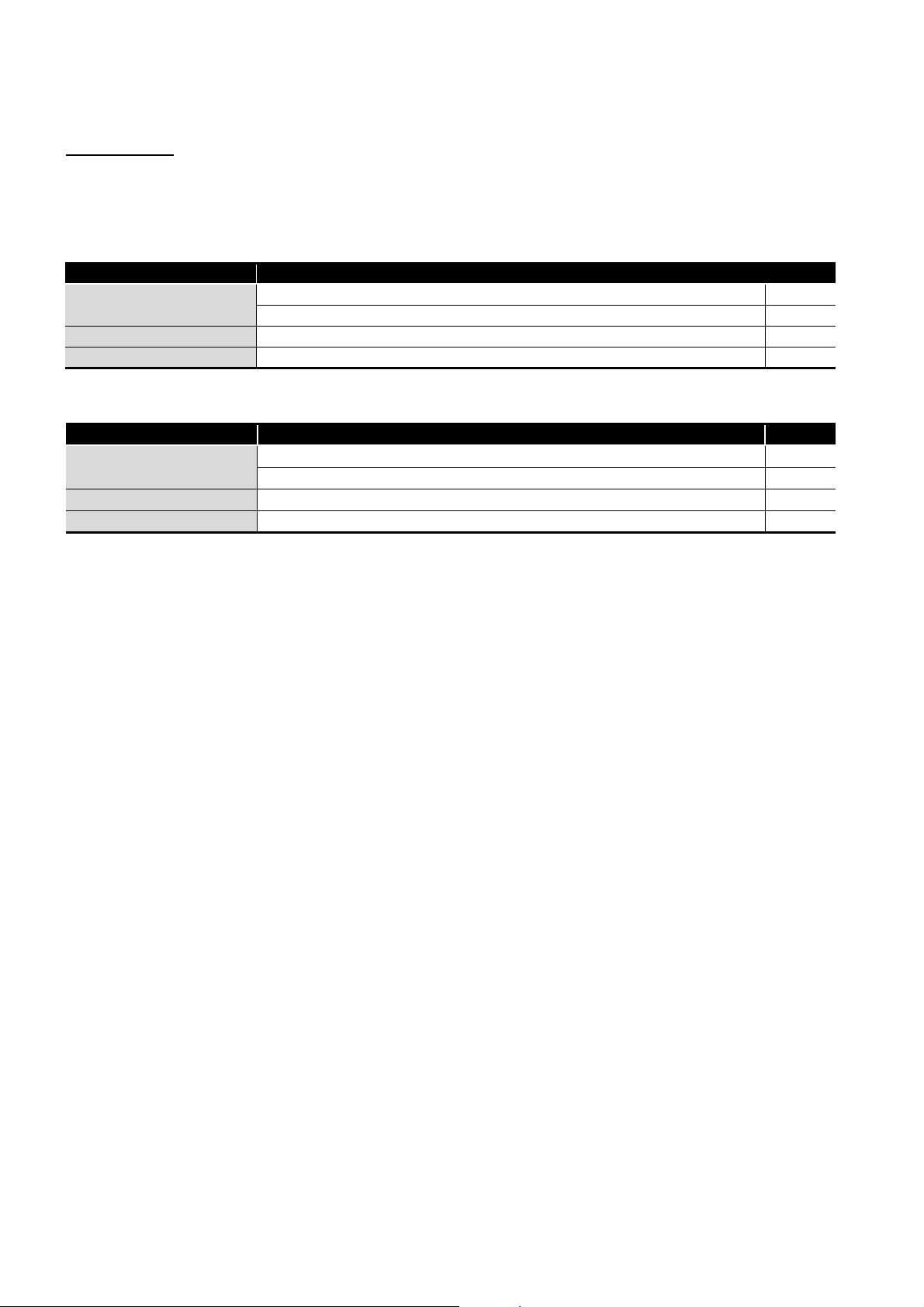
(1) Q68TD-G-H02
Model Product Quantity
Q68TD-G-H02
SW1D5C-QTIU-E GX Configurator-TI Version 1 (Single license product) (CD-ROM) 1
SW1D5C-QTIU-EA GX Configurator-TI Version 1 (Volume license product) (CD-ROM) 1
Q68TD-G-H02 channel isolated thermocouple input module 1
Cold junction temperature compensation resistor (RTD) 1
(2) Q68TD-G-H01
Model Product Quantity
Q68TD-G-H01
SW1D5C-QTIU-E GX Configurator-TI Version 1 (Single license product) (CD-ROM) 1
SW1D5C-QTIU-EA GX Configurator-TI Version 1 (Volume license product) (CD-ROM) 1
Q68TD-G-H01 channel isolated thermocouple input module 1
Cold junction temperature compensation resistor (RTD) 1
A - 14
1
OVERVIEW
CHAPTER 1 OVERVIEW
This user's manual provides the specifications, handling instructions, programming
procedures and other information of the Q68TD-G-H02 or Q68TD-G-H01 channel isolated
thermocouple input module (hereafter abbreviated as Q68TD-G-H02 (H01)), which is
designed to use with the MELSEC-Q series CPU module (referred to as the
programmable controller CPU).
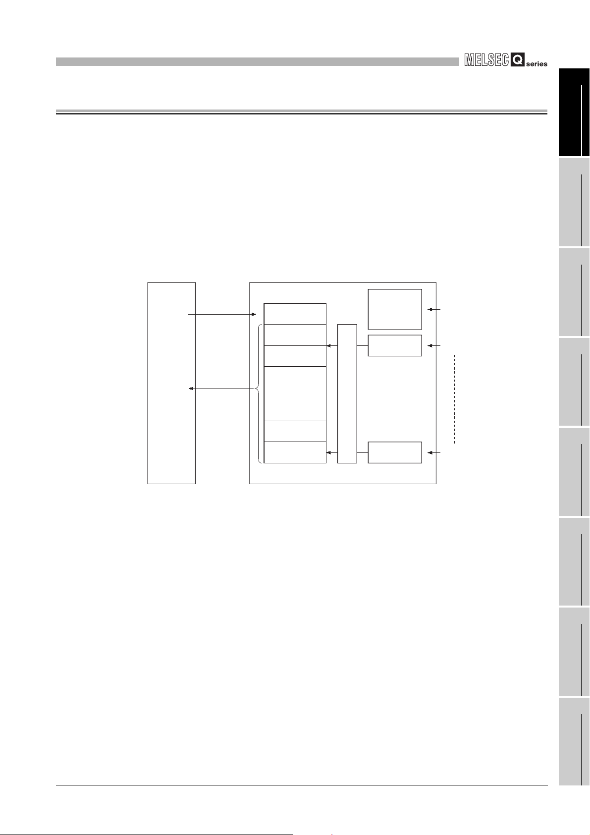
The Q68TD-G-H02(H01) is a module designed to convert thermocouple input values from
outside the programmable controller into 16-bit signed binary measured temperature
values and 16-bit signed binary scaling values (ratios).
Programmable
controller CPU
Q68TD-G-H02(H01)
1
2
3
OVERVIEW
SYSTEM
CONFIGURATION
TO
instruction
FROM
instruction
(Buffer memory)
Initial setting
Measured
temperature value,
scaling value
reading
Figure 1.1 Overview of Q68TD-G-H02(H01)
* 1 Refer to Section 3.4.17 for details of the scaling values.
Set data
Measured
temperature value
Scaling value
Measured
temperature value
Scaling value
1
*
1
*
Cold junction
temperature
compensation
channel
Channel 1
Temperature measurement
Channel 8
Resistance temperature
detector input
(by cold junction temperature
compensation resistor (RTD))
Thermocouple input
Thermocouple input
SPECIFICATIONS
4
SETUP AND
PROCEDURES BEFORE
OPERATION
5
UTILITY PACKAGE (GX
CONFIGURATOR-TI)
6
PROGRAMMING
7
ONLINE MODULE
CHANGE
8
TROUBLESHOOTING
1 - 1

1
OVERVIEW
1.1 Features
(1) Channels isolated
Q68TD-G-H02(H01) is channel isolated modules.
(2) 8 channels of temperatures measured by one module
One Q68TD-G-H02(H01) module can measure temperatures of 8 channels.
It can also convert the detected temperature values into scaling values (ratios (%)).
(3) Setting of conversion enable/disable
Conversion enable/disable setting for each channel is possible. Disabling conversion
for unused channels prevents unnecessary disconnection detection or monitor of
disconnection state on unused channels.
(4) Use of thermocouples conforming to JIS or IEC standards
Eight types of thermocouple (K, E, J, T, B, R, S, N) conforming to JIS or IEC standards
can be used.
A thermocouple type can be selected for each channel.
(5) Disconnection detection function (Q68TD-G-H02 only)
Disconnection status of thermocouple or compensating lead wire can be detected for
each channel by Disconnection detection flag.
Disconnection status can also be detected from the measured temperature value by
setting "Up scale", "Down scale" or "Given value" for the Conversion setting for
disconnection detection.
(6) Disconnection monitor function (Q68TD-G-H01 only)
Disconnection status of thermocouple or compensating lead wire can be checked on
each channel by Disconnection state monitor flag.
Disconnection status can also be checked from the measured temperature value by
setting "Up scale", "Down scale" or "Given value" for the Conversion setting for
disconnection detection.
(7) Selection of sampling processing, time average processing, count average
processing, moving average processing, and primary delay filter
As a conversion processing method, sampling processing, time average processing,
count average processing, moving average or primary delay filter can be selected for
each channel.
(8) Cold junction temperature compensation by cold junction temperature
compensation resistor (RTD)
Cold junction temperature compensation is possible by connecting the supplied cold
junction temperature compensation resistor (RTD) and enabling the cold junction
temperature compensation.
Resistance temperature detector Pt100 is used for cold junction temperature
compensation resistor (RTD).
1 - 2
1.1 Features

1
OVERVIEW
(9) Error compensation by offset/gain value setting
Error compensation can be made by setting offset and gain values on each channel.
As the offset and gain values, you can make selection from user range setting and
factory default setting.
(10)Warning output function
(a) Process alarm warning output
(b) Rate alarm warning output
A warning can be output when the input range set by the user is exceeded.
Upper limit value and lower limit value can be set for each channel, and a setting
to have a difference (hysteresis) between warning output and warning clear is
also possible.
By setting a changing rate, a warning can be output when the changing rate is
exceeded.
1
2
3
OVERVIEW
SYSTEM
CONFIGURATION
(11) Online module change
The module can be changed without stopping the system.
Furthermore, the following operations can be processed by using sequence
programs.
• Transferring the offset/gain set values to the replacement Q68TD-G-H02 (H01)
• Transferring the offset/and gain set values to another Q68TD-G-H02 (H01)
mounted on the other slot
(12)Easy settings using GX Configurator-TI
Using GX Configurator-TI which is sold separately, sequence programs can be
reduced since settings of the Q68TD-G-H02 (H01) can be made on the screen.
Also, the set status or operating status of the module can be checked easily.
SPECIFICATIONS
4
SETUP AND
PROCEDURES BEFORE
OPERATION
5
UTILITY PACKAGE (GX
CONFIGURATOR-TI)
6
PROGRAMMING
7
1.1 Features
ONLINE MODULE
CHANGE
8
TROUBLESHOOTING
1 - 3

2
Remark
SYSTEM CONFIGURATION
CHAPTER 2 SYSTEM CONFIGURATION
This chapter explains the system configuration of the Q68TD-G-H02 (H01).
2.1 Applicable Systems
This section describes applicable systems.
(1) Applicable modules and base units, and number of modules
(a) When mounted with a CPU module
For the CPU modules, the number of modules, and base units applicable to the
Q68TD-G-H02 (H01), refer to the user's manual for the CPU module used.
Note the following when the Q68TD-G-H02 (H01) is mounted with a CPU module.
• Depending on the combination with other modules or the number of mounted
modules, power supply capacity may be insufficient. Pay attention to the
power supply capacity before mounting modules, and if the power supply
capacity is insufficient, change the combination of the modules.
• Mount a module within the number of I/O points for the CPU module.
If the number of slots is within the available range, the module can be
mounted on any slot.
To use the Q68TD-G-H02 (H01) with a C Controller module, refer to the user's
manual for the C Controller module.
(b) When the module is used in a MELSECNET/H remote I/O station
For the MELSECNET/H remote I/O station, the number of modules, and base
units applicable to the Q68TD-G-H02 (H01), refer to the Q Corresponding
MELSECNET/H Network System Reference Manual (Remote I/O network).
(2) Restrictions on mountable slot position
(a) Restrictions in using both the Q68TD-G-H02 and Q68TD-G-H01
When mounting the Q68TD-G-H02 and Q68TD-G-H01 on the same base unit,
provide one or more than one slot of space between the Q68TD-G-H02 and
Q68TD-G-H01.
2 - 1
2.1 Applicable Systems
2
OUT
IN
I/01 I/01
Slot
No.0
Not mountable Mountable
Slot
No.1
Slot
No.2
Power
supply
SYSTEM CONFIGURATION
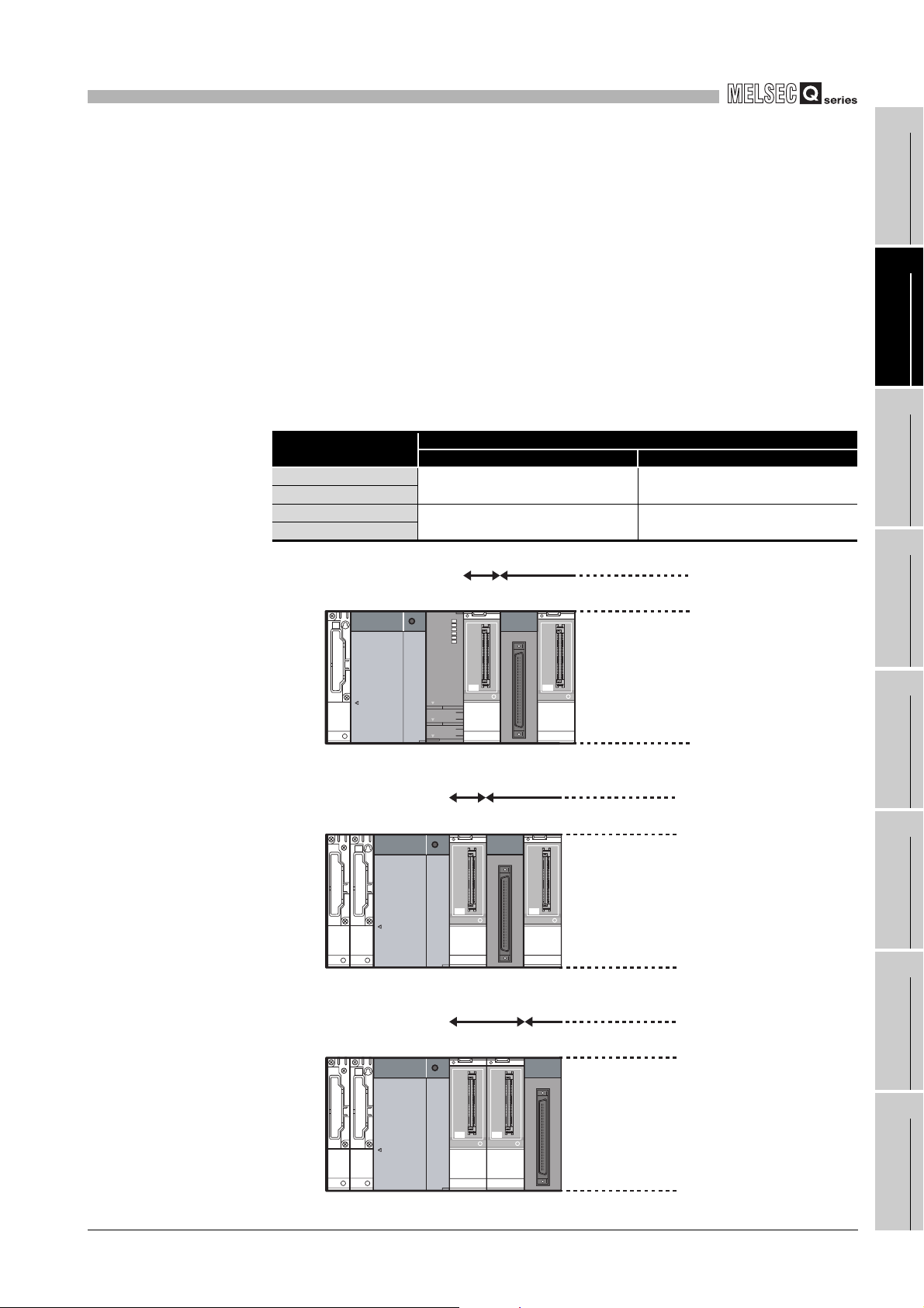
(b) Restriction on mountable slot position of the Q68TD-G-H01
The Q68TD-G-H01 has restrictions on mountable slot position.
The following describes the restrictions of the slot position when mounting the
Q68TD-G-H01 with a combination of the power supply module and the base unit.
For the slot that the Q68TD-G-H01 cannot be mounted, leave the slot open or
mount a module other than the Q68TD-G-H01.
The combination use of modules other than the following power supply modules
and the base units does not have restrictions.
When using the Q68TD-G-H01 on the remote I/O station, the restriction is the
same as for the main base unit.
When failing to comply with the following restrictions, the accuracy might not be in
the specification range.
Table 2.1 Restriction on mountable slot position
Power supply module
Q63P
Q63RP
Q64P Mount the module to I/O slot No.1 or
Q64RP
1)
No restrictions
later. 1)
Restrictions
Main base unit Extension base unit
Mount the module to I/O slot No.1 or
later. 2)
Mount the module to I/O slot No.2 or
later. 3)
Not mountable
Mountable
1
2
3
4
OVERVIEW
SYSTEM
CONFIGURATION
SPECIFICATIONS
Power
supply
OUT
Figure 2.1 Mountable slot position of Q68TD-G-H01
2)
Power
supply
OUT
IN
Figure 2.2 Mountable slot position of Q68TD-G-H01
Slot
CPU
No.0
I/01 I/01
Not mountable
Slot
No.0
I/01 I/01
Slot
No.1
Mountable
Slot
No.1
Slot
No.2
Slot
No.2
3)
SETUP AND
PROCEDURES BEFORE
OPERATION
5
UTILITY PACKAGE (GX
CONFIGURATOR-TI)
6
PROGRAMMING
7
ONLINE MODULE
CHANGE
8
Figure 2.3 Mountable slot position of Q68TD-G-H01
2.1 Applicable Systems
TROUBLESHOOTING
2 - 2
2
POINT
SYSTEM CONFIGURATION
(3) Support of the multiple CPU system
When using the Q68TD-G-H02 (H01) in a multiple CPU system, refer to the following
manual first.
• QCPU User's Manual (Multiple CPU System).
(4) Compatibility with online module change
The Q68TD-G-H02 (H01) is compatible with online module change from the initial
product with function version C.
Refer to CHAPTER 7.
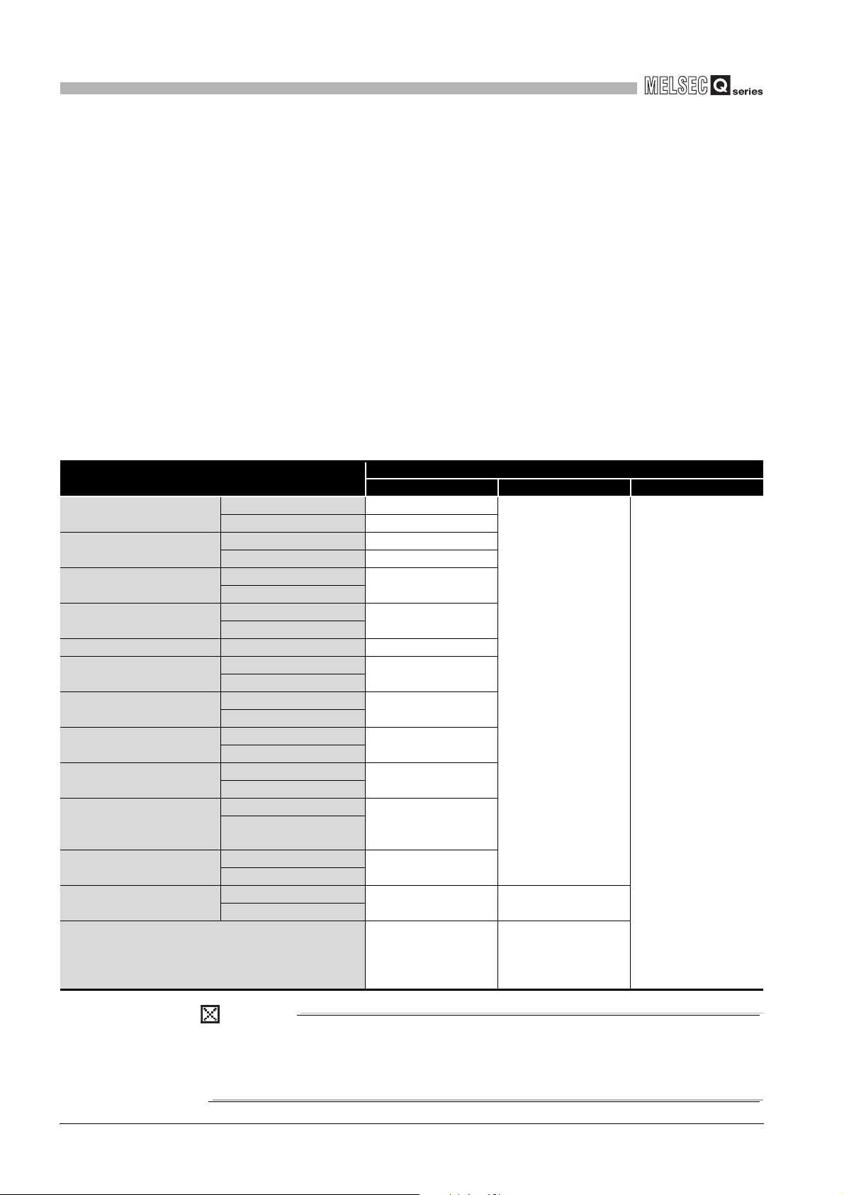
(5) Supported software packages
Relation between the system containing the Q68TD-G-H02 (H01) and software
package is shown in the following table.
GX Developer or GX Works2 is required to use the Q68TD-G-H02 (H01).
Table 2.2 System and compatible software package
System
Q00J/Q00/Q01CPU
Q02/Q02H/Q06H/Q12H/
Q25HCPU
Q02PH/Q06PHCPU
Q12PH/Q25PHCPU
Q12PRH/Q25PRHCPU Redundant system Version 8.45X or later
Q00UJ/Q00U/Q01UCPU
Q02U/Q03UD/Q04UDH/
Q06UDHCPU
Q10UDH/Q20UDHCPU
Q13UDH/Q26UDHCPU
Q03UDE/Q04UDEH/
Q06UDEH/Q13UDEH/
Q26UDEHCPU
Q10UDEH/Q20UDEHCPU
CPU modules other than the
above
If installed in a MELSECNET/H remote I/O station Version 6 or later
Single CPU system Version 7 or later
Multiple CPU system Version 8 or later
Single CPU system Version 4 or later
Multiple CPU system Version 6 or later
Single CPU system
Multiple CPU system
Single CPU system
Multiple CPU system
Single CPU system
Multiple CPU system
Single CPU system
Multiple CPU system
Single CPU system
Multiple CPU system
Single CPU system
Multiple CPU system
Single CPU system
Multiple CPU system
Single CPU system
Multiple CPU system
Single CPU system
Multiple CPU system
GX Developer GX Configurator-TI GX Works2
Version 8.68W or later
Version 7.10L or later
Version 8.76E or later
Version 8.48A or later
Version 8.76E or later
Version 8.62Q or later
Version 8.68W or later
Version 8.76E or later
Cannot be used Cannot be used
Software version
Version 1.28AE or later
(Q68TD-G-H02)
Version 1.24AA or later
(Q68TD-G-H01)
Version 1.28AE or later
(Q68TD-G-H02)
Version 1.24AA or later
(Q68TD-G-H01)
Refer to the GX Works2
Version 1 Operating
Manual (Common).
2 - 3
When using GX Works2, refer to the following:
• GX Works2 Version 1 Operating Manual (Common)
• GX Works2 Version 1 Operating Manual (Intelligent Function Module)
2.1 Applicable Systems
2
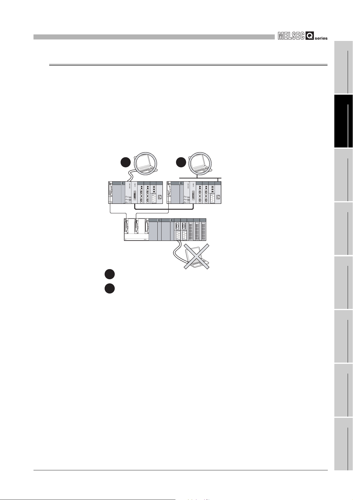
Main base unit
Extension base unit
12
1
Direct connection to use the CPU
2
Connection through an intelligent function module on the main base unit
(Through Ethernet module, MELSECNET/H module, or CC-Link module)
(GX Configurator-TI cannot be used.)
SYSTEM CONFIGURATION
2.2 When Using the Q68TD-G-H02 (H01) in the Redundant System
This section describes the use of the Q68TD-G-H02 (H01) in the redundant system.
1
(1) Dedicated instruction
The dedicated instruction cannnot be used.
(2) GX Configurator-TI
Configurator-TI cannot be used when accessing Redundant CPU via an intelligent
function module on an extension base unit from GX Developer. Connect a personal
computer with a communication path indicated below.
OVERVIEW
2
SYSTEM
CONFIGURATION
3
SPECIFICATIONS
4
SETUP AND
PROCEDURES BEFORE
OPERATION
5
Figure 2.4 Communication path available for GX Configurator-TI
2.2 When Using the Q68TD-G-H02 (H01) in the Redundant System
UTILITY PACKAGE (GX
CONFIGURATOR-TI)
6
PROGRAMMING
7
ONLINE MODULE
CHANGE
8
TROUBLESHOOTING
2 - 4
2
)
SYSTEM CONFIGURATION
2.3 How to Check the Function Version, Serial No., and Software
Version
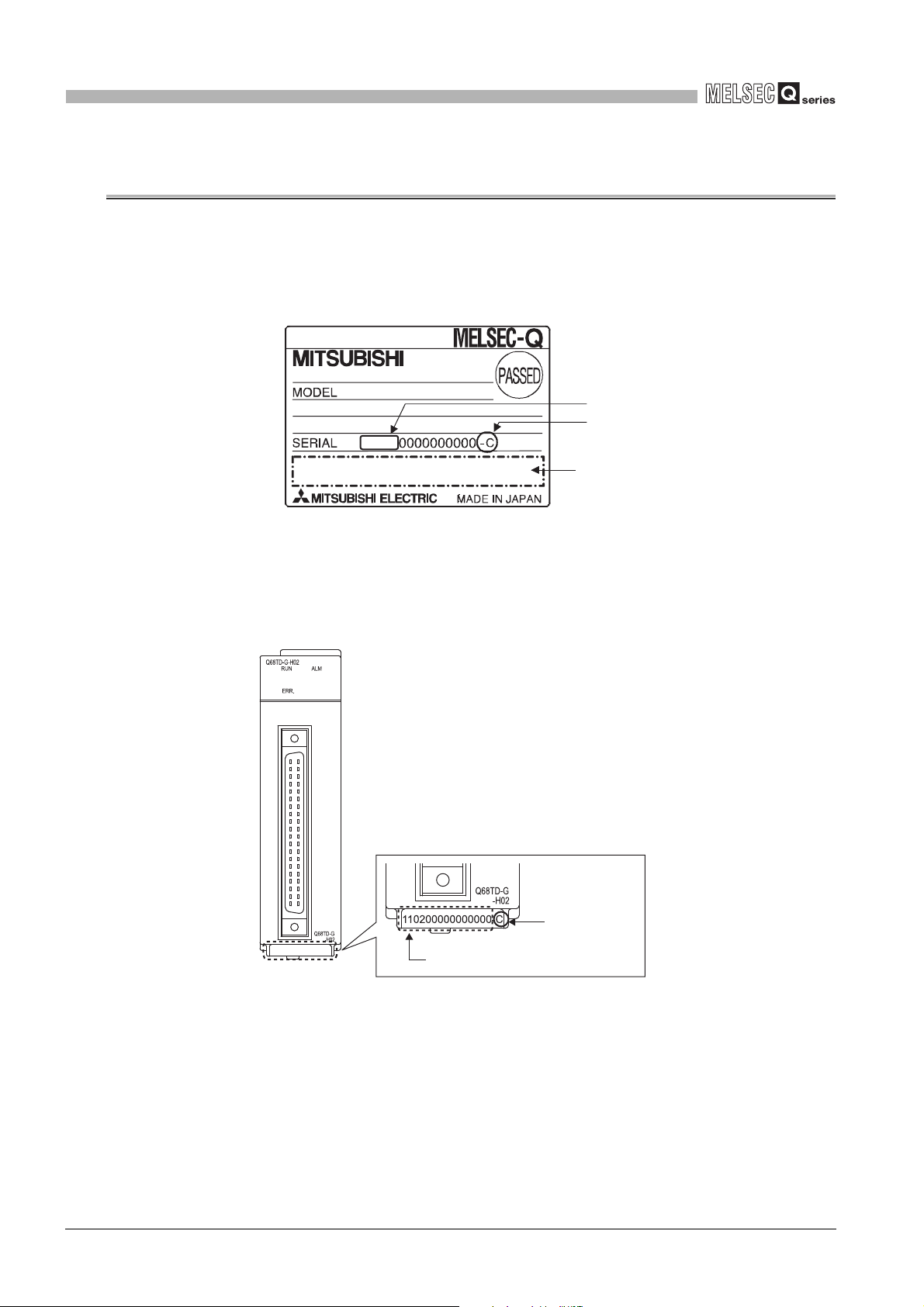
(1) Checking the function version and serial No.
(a) On the rating plate
The rating plate is put on the side of the Q68TD-G-H02 (H01).
(b) On the front of the module
The function version and serial No. on the rating plate is also indicated on the
front of the module (lower part).
11020
Figure 2.5 Rating plate
Serial No. (first 5 digits
Function version
Relevant regulation
standards
2 - 5
Function version
Serial No.
2.3 How to Check the Function Version, Serial No., and Software Version
2
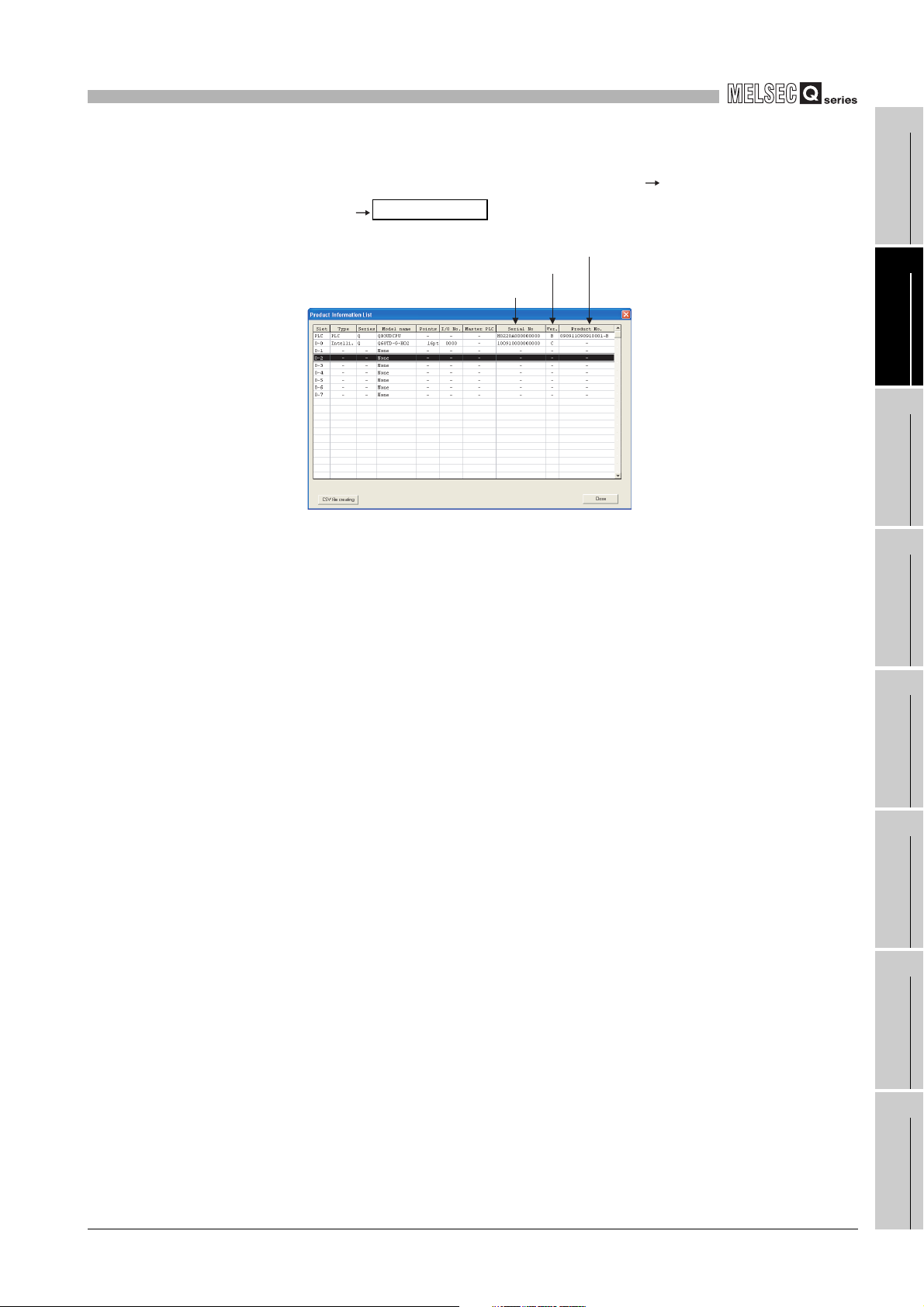
Product Inf. List
Serial No.
Function version
Product No.
SYSTEM CONFIGURATION
(c) On the system monitor (product information list)
To display the system monitor, select [Diagnostics] [System
monitor] of GX Developer.
1
2
3
OVERVIEW
SYSTEM
CONFIGURATION
Figure 2.6 "Product Information List" screen
1) Production number
Production number indication is not available for the Q68TD-G-H02 (H01); "-"
is shown.
SPECIFICATIONS
4
SETUP AND
PROCEDURES BEFORE
OPERATION
5
UTILITY PACKAGE (GX
CONFIGURATOR-TI)
6
PROGRAMMING
7
2.3 How to Check the Function Version, Serial No., and Software Version
ONLINE MODULE
CHANGE
8
TROUBLESHOOTING
2 - 6
2
POINT
SYSTEM CONFIGURATION
The serial No. on the rating plate and the front of the module may be different from
the serial No. displayed on the product information list in GX Developer.
• The serial No. on the rating plate and the front of the module indicates the
management information of the product.
• The serial No. displayed on the product information list in GX Developer
indicates the function information of the product. The function information
of the product is updated when a new function is added.
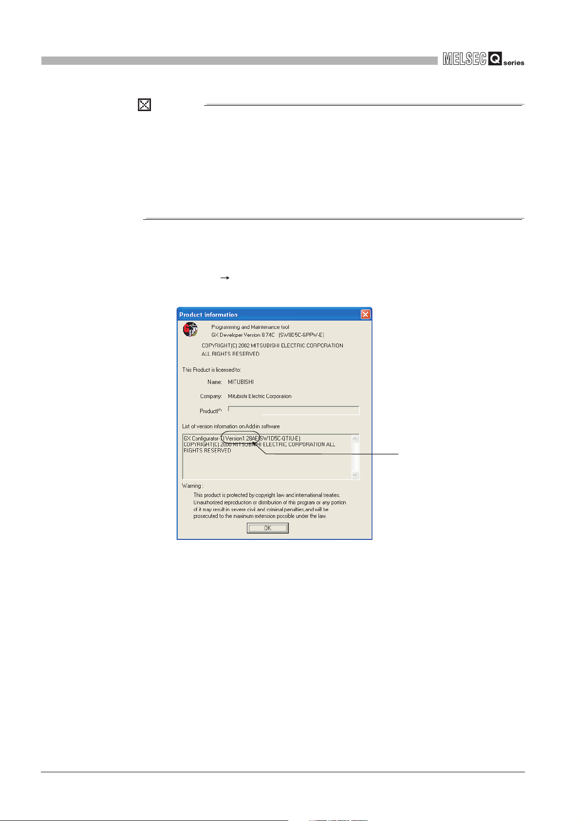
(2) Checking the software version of GX Configurator- TI
The software version of GX Configurator-TI can be checked on GX Developer by
clicking [Help] [Product information].
("Product information" screen of GX Developer Version 8)
Figure 2.7 How to check the software version of GX Configurator- TI
Software version
2 - 7
2.3 How to Check the Function Version, Serial No., and Software Version
3
SPECIFICATIONS
CHAPTER 3 SPECIFICATIONS
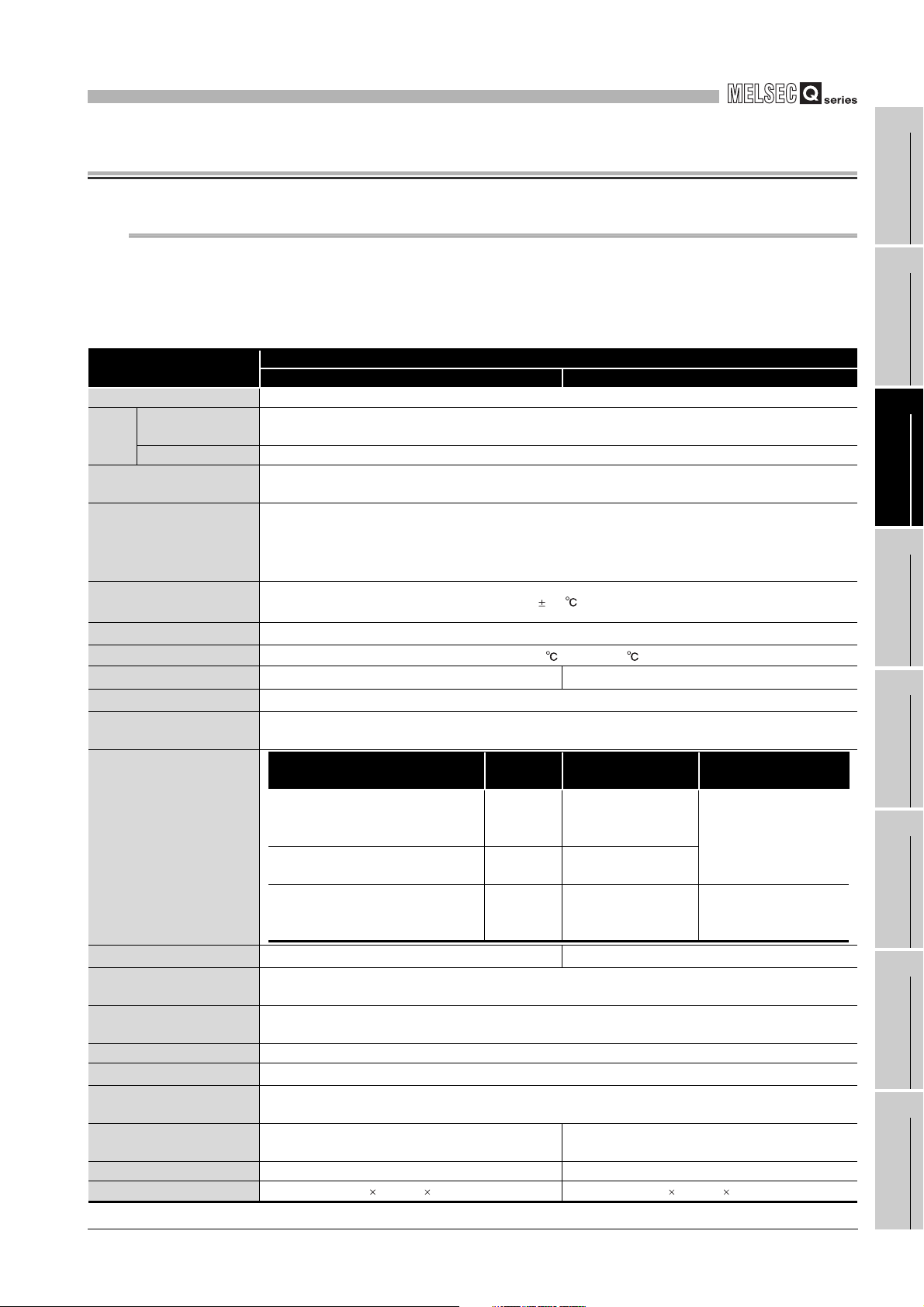
3.1 Performance Specifications
The following are the performance specifications of the Q68TD-G-H02 (H01).
(1) List of performance specifications
Table 3.1 List of performance specifications
Item
Number of channels 8 channels
Measured
Output
Thermocouple compliance
standards
Applicable thermocouples,
conversion accuracy
effect from wiring resistance
of 1
Cold junction compensation
accuracy
Accuracy
Resolution
Conversion speed
Sampling period
Number of analog input
channels
Isolation specifications
Disconnection detection
Maximum number of writes to
flash memory
Number of I/O points
occupied
External interface 40-pin connector
Applicable wire size
External device connector
(sold separately)
Internal current consumption
(5VDC)
Weight 0.22kg 0.18kg
External dimensions
temperature value
Scaling value 16-bit signed binary
*1
, and
*1
*1
*3
*4
Specific isolated area
Between thermocouple input channel
and programmable controller power
Between thermocouple input
Between cold junction compensation
channel and programmable controller
Available (each channel respectively)
Q68TD-G-H02 Q68TD-G-H01
16-bit signed binary (-2700 to 18200)
JIS C1602-1995,IEC 60584-1(1995),IEC60584-2(1982)
640ms/8 channels 320ms/8 channels
8 channels + cold junction compensation channels/ 1 module
supply
channels
power supply
16 points (I/O assignment: Intelligent 16 points)
2
0.3mm
(AWG22) or less (for A6CON1, A6CON4), 0.24mm2(AWG24) (for A6CON2)
0.65A 0.49A
102(H) 27.4(W) 130(D)mm 98(H) 27.4(W) 90(D)mm
Specifications
Refer to (2) in this section
1.0
Caluculated with formula
B,R,S,N: 0.3 K,E,J,T: 0.1
320ms/8 channels
Isolation
method
Transfer
isolation
Trasnfer
isolation
No isolation - -
*5
A6CON1, A6CON2, A6CON4
Dielectric withstand
500VACrms for 1min
1000VACrms for 1min
50,000
*2
voltage
Not available
Isolation resistance
500VDC 10M or more
*6
1
OVERVIEW
2
SYSTEM
CONFIGURATION
3
SPECIFICATIONS
4
SETUP AND
PROCEDURES BEFORE
OPERATION
5
UTILITY PACKAGE (GX
CONFIGURATOR-TI)
6
PROGRAMMING
7
ONLINE MODULE
CHANGE
8
3.1 Performance Specifications
TROUBLESHOOTING
3 - 1

3
SPECIFICATIONS
* 1 To satisfy with the accuracy, a warm-up (power distribution) period of 30 minutes is required.
* 2 Calculate the accuracy in the following method.
(Accuracy) = (conversion accuracy) + (temperature characteristic) (operating ambient
temperature variation) + (cold junction temperature compensation accuracy)
An operating ambient temperature variation indicates a deviation of the operating ambient
temperature from the 25 5 range.
Example: When using the thermocouple B (refer to Section 3.1 (2)) with the operating ambient
temperature of 35 and the measured temperature of 1000 , the accuracy is as follows.
( 2.5 )+( 0.4 ) (35 -30 )+( 1 )= 5.5
* 3 The conversion speed indicates the maximum time from when the input temperature changes till
when the measured temperature value of buffer memory is batch-updated.
* 4 The sampling period indicates the period batch-updating the measured temperature value in one
channel.
* 5 When disconnection state is detected, output values are selected from "Up scale", "Down scale"
or Given scale". (Refer to Section 3.2.2)
* 6 The Q68TD-G-H01 does not have the disconnection detection function. However, the
disconnection monitor function is available to select a measured temperature value on a
disconnection occurrence from either "Up scale", "Down scale", or "Given value". (Refer to
Section 3.2.3)
It takes up to 11s to check a disconnection state.
3 - 2
3.1 Performance Specifications
3
Usable
Thermo
couple
Typ e
B
R
S
K
E
J
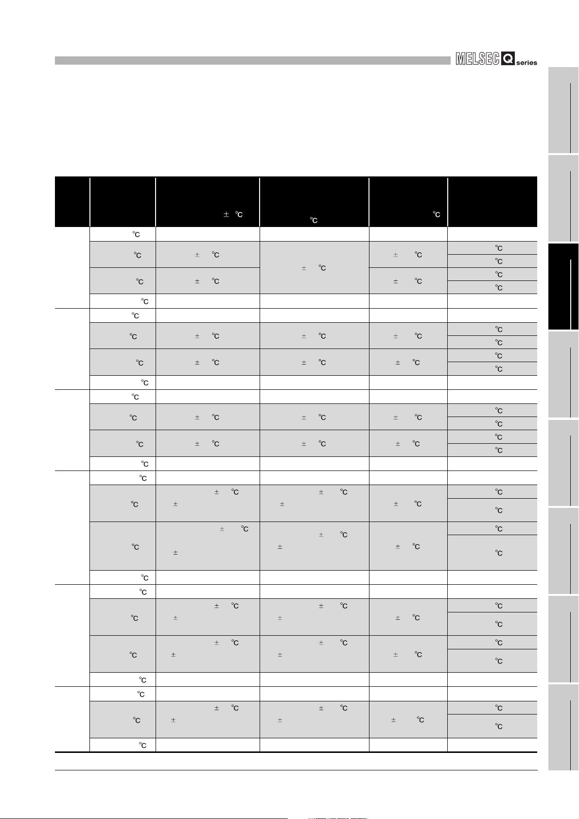
SPECIFICATIONS
(2) Applicable thermocouples, conversion accuracy, and effect from wiring
resistance of 1
The following table lists applicable thermocouples, conversion accuracy, and the
effect from wiring resistance of 1.
Table 3.2 Applicable thermocouples, conversion accuracy, and the effect from wiring resistance of 1
Measured
Temperature
Range
0 to 600
600 to 800
800 to 1700
1700 to 1820
-50 to 0
0 to 300
300 to 1600
1600 to 1760
-50 to 0
0 to 300
300 to 1600
1600 to 1760
-270 to -200
-200 to 0
0 to 1200
1200 to 1370
-270 to -200
-200 to 0
0 to 900
900 to 1000
-210 to -40
-40 to 750
750 to 1200
Conversion Accuracy
(At operating ambient
*1
*2
*2
*2
temperature 25 5 )
*2
*2
*2
*2
Larger value of 0.5 and
*2
*2
*2
*2
0.5% of measured
temperature
Larger value of 0.25
0.5% of measured
temperature
Larger value of 0.5 and
0.5% of measured
temperature
Larger value of 0.5 and
0.25% of measured
temperature
Larger value of 0.5 and
0.25% of measured
temperature
*3
------
3.0
2.5 12.5
*3
------
*3
------
2.5 0.4 12.5
2.0 0.3 9.5
*3
------
*3
------
2.5 0.4 12.5
2.0 0.3 9.5
*3
------
*3
------
and
*3
------
*3
------
*3
------
*3
------
*3
------
Temperature Characteristic
(Per operating ambient
temperature variation of
1 )
*3
------
0.4
*3
------
*3
------
*3
------
*3
------
*3
------
*3
------
Larger value of 0.06 and
0.2% of measured
temperature
Larger value of 0.06 and
0.02% of measured
temperature
*3
------
*3
------
Larger value of 0.06 and
0.15% of measured
temperature
Larger value of 0.06 and
0.02% of measured
temperature
*3
------
*3
------
Larger value of 0.06 and
0.02% of measured
temperature
*3
------
Max. Temperature
Error at Ambient
Temperature 55
*3
------
13.0
*3
------
*3
------
*3
------
*3
------
*3
------
*3
------
11. 0
9.0
*3
------
*3
------
8.5
6.75
*3
------
*3
------
5.625
*3
------
Effect from wiring
*4
resistance of 1
(upper: Q68TD-G-H02
lower: Q68TD-G-H01)
------
-0.169 /
-0.042 /
-0.143 /
-0.036 /
------
------
-0.200 /
-0.050 /
-0.112 /
-0.028 /
------
------
-0.200 /
-0.050 /
-0.112 /
-0.028 /
------
------
-0.034 /
-0.009 /
-0.026 /
-0.007 /
------
------
-0.023 /
-0.006 /
-0.018 /
-0.005 /
------
------
-0.022 /
-0.006 /
------
*3
*3
*3
*3
*3
*3
*3
*3
*3
*3
*3
*3
1
OVERVIEW
2
SYSTEM
CONFIGURATION
3
SPECIFICATIONS
4
SETUP AND
PROCEDURES BEFORE
OPERATION
5
UTILITY PACKAGE (GX
CONFIGURATOR-TI)
6
PROGRAMMING
7
ONLINE MODULE
CHANGE
8
3.1 Performance Specifications
TROUBLESHOOTING
3 - 3
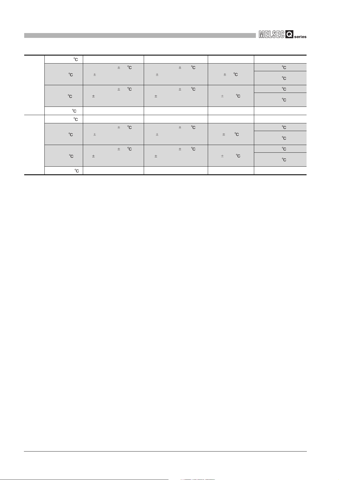
3
T
N
SPECIFICATIONS
Table 3.2 Applicable thermocouples, conversion accuracy, and the effect from wiring resistance of 1
-270 to -200
-200 to 0
0 to 350
350 to 400
-270 to -200
-200 to 0
0 to 1250
1250 to 1300
------
Larger value of 0.5 and
*2
*2
*2
*2
0.5% of measured
temperature
Larger value of 0.5 and
0.25% of measured
temperature
------
------
Larger value of 0.5 and
0.5% of measured
temperature
Larger value of 0.5 and
0.25% of measured
temperature
------
* 1 If a value entered from the thermocouple is outside the measured temperature range given in the
* 2 The accuracies only in the temperature ranges of Class 1 to 3 (shaded areas) in JIS C1602-1995
* 3 Temperature measurement can be executed, but accuracy is not guaranteed.
* 4 This is the temperature error per 1 wiring resistance of the thermocouple. Check the wiring
*3
Larger value of 0.06 and
0.1% of measured
Larger value of 0.06 and
0.02% of measured
*3
*3
Larger value of 0.06 and
0.2% of measured
Larger value of 0.06 and
0.02% of measured
*3
table, it is handled as the maximum/minimum value of the measured temperature range.
apply.
Also, a warm-up (power distribution) period of 30 minutes is required to satisfy with the accuracy.
resistance value and calculate the temperature error in the system. If the error exceeds the
allowable range of the system, correct the measured temperature value by the offset/gain setting.
(Refer to Section 4.6.)
*3
------
temperature
temperature
*3
------
*3
------
temperature
temperature
*3
------
------
6.0
2.625
------
------
11.0
9.375
------
*3
*3
*3
*3
*3
------
-0.036 /
-0.009 /
-0.026 /
-0.007 /
*3
------
*3
------
-0.048 /
-0.012 /
-0.039 /
-0.010 /
*3
------
3 - 4
3.1 Performance Specifications
 Loading...