

Mitsubishi Electric QJ71C24-R2, QJ71C24N-R2, QJ71C24N-R4, QJ71C24, GX Configurator-SC User Manual

Q Corresponding Serial Communication Module
User's Manual (Basic)
-QJ71C24N
-QJ71C24N-R2
-QJ71C24N-R4
-QJ71C24
-QJ71C24-R2
-GX Configurator-SC (SW2D5C-QSCU-E)

SAFETY PRECAUTIONS
(Read these precautions before using this product.)
Before using this product, please read this manual and the relevant manuals carefully and pay full attention
to safety to handle the product correctly.
The instructions given in this manual are concerned with this product. For the safety instructions of the
programmable controller system, please read the user's manual of the CPU module to use.
In this manual, the safety precautions are classified into two levels: " WARNING" and " CAUTION".
Under some circumstances, failure to observe the precautions given under " CAUTION" may lead to
serious consequences.
Observe the precautions of both levels because they are important for personal and system safety.
Make sure that the end users read this manual and then keep the manual in a safe place for future reference.
[Design Precautions]
!
WARNING
For the operation status of each station at communication error in each station, refer to the
respective manual for each station.
The communication error may result in an accident due to incorrect output or malfunction.
When using the notification function, the pager receiver may not be contacted due to the frequency
transmission status from the system setup environment and error on the receiver side.
To ensure the safety of the programmable controller system, install a call circuit with a lamp
display or buzzer sound.
When connecting a peripheral with the CPU module or connecting an external device, such as a
personal computer, with an intelligent function module to modify data of a running
programmable controller, configure an interlock circuit in the program to ensure that the entire
system will always operate safely.
For other forms of control (such as program modification or operating status change) of a
running programmable controller, read the relevant manuals carefully and ensure that the
operation is safe before proceeding.
Especially, when a remote programmable controller is controlled by an external device,
immediate action cannot be taken if a problem occurs in the programmable controller due to a
communication failure.
To prevent this, configure an interlock circuit in the program, and determine corrective actions to
be taken between the external device and CPU module in case of a communication failure.
A - 1 A - 1
[Design Precautions]
!
WARNING
Do not write any data to the "system area" of the buffer memory in the intelligent function
module.
Also, do not use any "use prohibited" signals as an output signal from the programmable
controller CPU to the intelligent function module.
Doing so may cause malfunction of the programmable controller system.
!
CAUTION
Do not install the control lines or communication cables together with the main circuit lines or
power cables.
Keep a distance of 100mm or more between them.
Failure to do so may result in malfunction due to noise.
When using the module while values, such as buffer memory set values, are registered in the
Flash ROM, do not turn off the power supply for the module loading station nor reset the
programmable controller CPU.
If the power supply for the module loading station is turned off or the programmable controller
CPU is reset while any values are registered, the data contents in the Flash ROM become
inconsistent and as a result the values must be set again in the buffer memory, etc. and
reregistered to the Flash ROM.
Also, this may cause failure and malfunction of the module.
[Installation Precautions]
!
CAUTION
Use the programmable controller in an environment that meets the general specifications in the
user's manual for the CPU module used.
Failure to do so may result in electric shock, fire, malfunction, or damage to or deterioration of
the product.
To mount the module, while pressing the module mounting lever located in the lower part of the
module, fully insert the module fixing projection(s) into the hole(s) in the base unit and press the
module until it snaps into place.
Incorrect mounting may cause malfunction, failure or drop of the module.
When using the programmable controller in an environment of frequent vibrations, fix the
module with a screw.
Tighten the screws within the specified torque range.
Undertightening can cause drop of the screw, short circuit or malfunction.
Overtightening can damage the screw and/or module, resulting in drop, short circuit, or
malfunction.
Shut off the external power supply (all phases) used in the system before mounting or removing
a module.
Failure to do so may result in damage to the product.
Do not directly touch any conductive parts and electronic components of the module.
Doing so can cause malfunction or failure of the module.
A - 2 A - 2

[Wiring Precautions]
!
CAUTION
When turning on the power and operating the module after installation and wiring are completed,
always attach the terminal cover that comes with the product.
There is a risk of electric shock if the terminal cover is not attached.
Perform correct pressure-displacement, crimp-contact or soldering for external wire connections
using the tools specified by the manufactures.
Incorrect connection may cause short circuits, fire, or malfunction.
Attach connectors to the module securely.
Place the cables in a duct or clamp them.
If not, dangling cable may swing or inadvertently be pulled, resulting in damage to the module or
cables or malfunction due to poor contact.
Before connecting the cables, check the type o f interface to be connected.
Connecting or erroneous wiring to the wrong interface may cause failure to the module and
external devices.
Tighten the terminal screws within the specified torque range.
Undertightening the terminal screws can cause short circuit or malfunction.
Overtightening can damage the screw and/or module, resulting in drop, short circuit, or
malfunction.
When disconnecting the cable from the module, do not pull the cable by the cable part. For the
cable with connector, hold the connector part of the cable.
For the cable connected to the terminal block, loosen the terminal screw.
Pulling the cable that is still connected to the module may cause malfunction or damage to the
module or cable.
Prevent foreign matter such as dust or wire chips from entering the module.
Such foreign matter can cause a fire, failure, or malfunction.
A protective film is attached to the top of the module to prevent foreign matter, such as wire
chips, from entering the module during wiring.
Do not remove the film during wiring.
Remove it for heat dissipation before system operation.
A - 3 A - 3
[Startup/Maintenance Precautions]
!
CAUTION
Do not disassemble or modify the modules.
Doing so may cause failure, malfunction, injury, or a fire.
Shut off the external power supply (all phases) used in the system before mounting or removing
the module.
Failure to do so may cause the module to fail or malfunction.
After the first use of the product, do not mount/remove the module to/from the base unit, and the
terminal block to/from the module more than 50 times (IEC 61131-2 compliant) respectively.
Exceeding the limit may cause malfunction.
Do not touch any terminal while power is on.
Doing so may cause malfunction.
Shut off the external power supply (all phases) used in the system before cleaning the module or
retightening the terminal screws or module fixing screws.
Failure to do so may cause the module to fail or malfunction.
Undertightening can cause drop of the screw, short circuit or malfunction.
Overtightening can damage the screw and/or module, resulting in drop, short circuit, or
malfunction.
Before handling the module, touch a conducting object such as a grounded metal to discharge
the static electricity from the human body.
Failure to do so may cause the module to fail or malfunction.
[Operation Precautions]
!
CAUTION
When changing data and operating status, and modifying program of the running programmable
controller from an external device such as a personal computer connected to an intelligent
function module, read relevant manuals carefully and ensure the safety before operation.
Failure to perform correct operations to change data, program, or the status may result in
system malfunction, machine damage, or an accident.
[Disposal Precautions]
!
CAUTION
When disposing of this product, treat it as industrial waste.
A - 4 A - 4

CONDITIONS OF USE FOR THE PRODUCT
(1) Mitsubishi programmable controller ("the PRODUCT") shall be used in conditions;
i) where any problem, fault or failure occurring in the PRODUCT, if any, shall not lead to any major or
serious accident; and
ii) where the backup and fail-safe function are systematically or automatically provided outside of the
PRODUCT for the case of any problem, fault or failure occurring in the PRODUCT.
(2) The PRODUCT has been designed and manufactured for the purpose of being used in general
industries.
MITSUBISHI SHALL HAVE NO RESPONSIBILITY OR LIABILITY (INCLUDING, BUT NOT LIMITED TO
ANY AND ALL RESPONSIBILITY OR LIABILITY BASED ON CONTRACT, WARRANTY, TORT,
PRODUCT LIABILITY) FOR ANY INJURY OR DEATH TO PERSONS OR LOSS OR DAMAGE TO
PROPERTY CAUSED BY the PRODUCT THAT ARE OPERATED OR USED IN APPLICATION NOT
INTENDED OR EXCLUDED BY INSTRUCTIONS, PRECAUTIONS, OR WARNING CONTAINED IN
MITSUBISHI'S USER, INSTRUCTION AND/OR SAFETY MANUALS, TECHNICAL BULLETINS AND
GUIDELINES FOR the PRODUCT.
("Prohibited Application")
Prohibited Applications include, but not limited to, the use of the PRODUCT in;
Nuclear Power Plants and any other power plants operated by Power companies, and/or any other
cases in which the public could be affected if any problem or fault occurs in the PRODUCT.
Railway companies or Public service purposes, and/or any other cases in which establishment of a
special quality assurance system is required by the Purchaser or End User.
Aircraft or Aerospace, Medical applications, Train equipment, transport equipment such as Elevator
and Escalator, Incineration and Fuel devices, Vehicles, Manned transportation, Equipment for
Recreation and Amusement, and Safety devices, handling of Nuclear or Hazardous Materials or
Chemicals, Mining and Drilling, and/or other applications where there is a significant risk of injury to
the public or property.
Notwithstanding the above, restrictions Mitsubishi may in its sole discretion, authorize use of the
PRODUCT in one or more of the Prohibited Applications, provided that the usage of the PRODUCT is
limited only for the specific applications agreed to by Mitsubishi and provided further that no special
quality assurance or fail-safe, redundant or other safety features which exceed the general specifications
of the PRODUCTs are required. For details, please contact the Mitsubishi representative in your region.
A - 5 A - 5
REVISIONS
The manual number is given on the bottom left of the back cover.
Print Date Manual Number Revision
Dec., 1999 SH (NA)-080006-A First edition
Oct., 2000 SH (NA)-080006-B Add the contents of the function version B.
Correction
Contents, Entire manual (change MELSECNET/10H to MELSECNET/H),
About Manuals, About The Generic Terms and Abbreviations, Product
Configuration, Section 1.2, 1.2(8), 1.3 POINT, Section 2.2, 2.3, 2.5, 2.6,
Section 3.1, 3.6, 3.9, Section 4.2, 4.4.1(2)(a)(Figure), 4.6(1), Chapter
5(all), Section 6.1.1, 6.1.3, 6.1.4, Section 7.1.1, 7.1.2, 7.2.2, Section 8.1,
8.2.1, 8.2.2, 8.3.1, 8.3.2, Section 9.2 to 9.7, Section 10.1.1, 10.2.1,
10.3.8, 10.3.18, Appendix 1.1(2), Appendix 2(all), Appendix 3(2),
Appendix 7, Appendix 8
Addition
Entire manual (add the explanation on MELSECNET/H remote I/O
station), The Manual's Use and Structure, Section 2.1, Section
3.1(Table), Section 4.4.2(1)(d), 4.9.2, Section 8.3.2 POINT, Section
10.2.1 (7164
Jun., 2001 SH (NA)-080006-C Put Windows base software product together from Mitsubishi
H, 7E70H), Appendix 3(1)
R
Programmable Controller MELSEC Series to Mitsubishi integrated FA
Software MELSOFT Series.
Standardize the name from software package (GPP function) to Product
name (GX Developer).
Standardize the name from utility package (QSCU) to Product name (GX
Configurator-SC).
Correction
Conformation to the EMC Directive and Low Voltage Instruction, About
the Generic Terms and Abbreviations, Product Configuration, Program
Examples (Section 6.1.4, 6.2.3, Section 7.2.3, Section 9.3, 9.5, Appendix-
8), Section 1.2(1)(d), 1.2(4)(b)(Diagram), 1.2(8)(b), 1.3, Section 2.1, 2.3,
2.4, 2.5, 2.7, Section 3.1(Table), 3.2.1(3), 3.3.3(2), 3.4(Table), 3.9,
Section 4.3, 4.5.2, Section 5.1.5(3), 5.2, Section 6.1.4, Section 8.2, 8.3.2
POINT, 8.4.2, 8.4.9(Table), 8.6.3(Table), 8.6.7(Table), Section 10.1.2(b),
10.3(Table), Appendix 1.1, 2.1, 6, 7, 9
Addition
Section 2.6, Section 8.4.4, 8.6.2(Table), Section 10.2.1(716FH, 7FEFH),
H), 10.3.14, Appendix 3
Feb., 2002 SH (NA)-080006-D
10.2.3(7FE9
Addition
About The Generic Terms and Abbreviations, Section 1.2, Section 2.1,
2.7, Section 4.5.2, Section 8.2.1, 8.2.2, Section 10.2.1, Appendix 1.1, 6
Oct., 2002 SH (NA)-080006-E
Addition
The Manual's Use and Structure, About The Generic Terms and
Abbreviations, Section 1.2(1)(4), Section 2.1, 2.4, Section 5.2, Section
6.1.4, Section 9.8, Appendix 7
Jan., 2003 SH (NA)-080006-F
Addition model
QJ71C24N, QJ71C24N-R2, QJ71C24N-R4
A - 6 A - 6
The manual number is given on the bottom left of the back cover.
Print Date Manual Number Revision
Jan., 2003 SH (NA)-080006-F
Addition
SAFETY PRECAUTIONS, About Manuals, About The Generic Terms
and Abbreviations, Product Configuration, Section 1.3, Section 2.1, 2.2,
2.3, 2.5, 2.6, 2.7, Section 3.1, 3.2.1, 3.3.1, 3.6, 3.8, 3.9, Section 4.1, 4.3,
4.4, 4.5, 4.6, 4.7.1, Section 6.1.1, 6.1.2, Section 7.1, 7.2.2, Chapter 8(all),
Section 9.1, 9.6, Section 10.1.2(b), 10.1.3(1), 10.2, Appendix 1, Appendix
2.1, Appendix 3, Appendix 5, Appendix 9
Jun., 2004 SH (NA)-080006-G
Correction
About The Generic Terms and Abbreviations, Product Configuration,
Chapter 2 (all), Section 3.8, Section 4.2.2 (1), Section 5.1.3 POINT,
Section 5.1.4, Chapter 8 (screen change), Section 8.6.10, Section 10.1.1,
Section 10.2
Addition
Appendix 9
Sep., 2004 SH (NA)-080006-H
Correction
Section 1.3, Section 2.5, 2.6, Section 3.5, 3.6, 3.9, Section 4.1, Chapter 8
(screen change), Section 8.6.9, 8.6.10, Section 10.1, 10.2, Appendix 1.1
Addition
Appendix 9.12
Feb., 2005 SH (NA)-080006-I
Correction
Section 2.1 (1), Section 3.1, Section 4.5.2 (1) ©, Chapter 9 (Simultaneous
execution of dedicated instructions), Section 10.2.1
Aug., 2005 SH (NA)-080006-J
Correction
SAFETY PRECAUTIONS, Section 3.3.1, 3.3.3, Section 8.2.2,
Section 9.4, Appendix 5, Appendix 7.1, 7.2
Feb., 2006 SH (NA)-080006-K
Mar., 2006 SH (NA)-080006-L
Correction
Section 2.6, Section 3.9, Section 8.2.1, 8.3.3, Section 9.1, Appendix 5
Correction
SAFETY PRECAUTIONS, Section 1.3, Section 2.6, Section 3.2.1, 3.8,
3.9, Section 8.6.9, Section 10.2.1, 10.3.11, Appendix 1
Addition
Section 10.1.7
Jan., 2008 SH (NA)-080006-M
Change of a term
"PLC" was changed to "programmable controller".
Correction
About The Generic Terms and Abbreviations, Section 1.2, 1.3, Section
2.1, 2.5, 2.7, Section 3.2.1, 3.2.2, 3.3.1, 3.9, Section 4.1, 4.3, 4.4, 4.5.2,
4.6, 4.9.2, Section 5.1.4, 5.2, Section 6.1.6, Chapter 8, Section 9.2 to 9.8,
Section 10.1.1, 10.1.6, 10.2.1,10.2.3, 10.3.3, 10.3.4, 10.3.8, 10.3.11,
10.3.19, Appendix 1.1, Appendix 2.1, Appendix 3, Appendix 5, Appendix
7.1
Addition
Section 2.5, Appendix 1.3
A - 7 A - 7
A
The manual number is given on the bottom left of the back cover.
Print Date Manual Number Revision
May, 2008 SH (NA)-080006-N
Correction
SAFETY PRECAUTIONS, About Manuals, Compliance with the EMC
and Low Voltage Directives, About The Generic Terms and
bbreviations, Section 1.2, 1.3, Section 2.1 to 2.3, 2.8, Section 4.1, 4.5.2,
Section 5.1.1, Section 8.2.1, 8.3.2, 8.3.3, Section 9.8, Section 10.1.1,
10.2.1, 10.3.3, 10.3.6, Appendices 1.1, 2.1, 3
Addition
Section 2.7
June, 2009 SH (NA)-080006-O
Correction
About Manuals, Manual's Use and Structure, About The Generic Terms
and Abbreviations, Definitions and Descriptions of Terminology,
Sections 1.2, 1.3, 2.1, 2.2, 2.4 to 2.6,
2.8, 3.1, 3.2.1, 3.3.4, 3.4 to 3.6, 3.8, 3.9, 4.1 to 4.3,
4.4.2, 4.5.2, 4.5.3, 4.6, 4.7, 4.7.1, 5.1.4, 5.1.5, 6.1.2,
6.1.4, 6.2.2, 7.1.2, and 7.2.2, Chapter 9, Sections 9.1, 9.2.1, 9.2.2,
9.3.1, 9.4, 9.4.5, 9.6.1, 9.6.3, 10.2 to 10.8, 11.1.1, 11.1.2, 11.1.5,
11.1.6, 11.2.1, 11.3, 11.3.1 to 11.3.3,
and 11.3.5 to 11.3.22, Appendices 1.1, 2.1, 3, 9.6, and 10
Partial addition
Section 3.3.4, Chapter 8, Sections 9.4.9, 9.6.7, 11.3.4, and 11.3.6
Section number change
Chapters 8 to 10 9 to 11, Sections 9.6.7 to 9.6.10 9.6.8 to 9.6.11,
Sections 9.4.9 to 9.4.11 9.4.10 to 9.4.12,
Section 11.3.4 11.3.5, Sections 11.3.5 to 11.3.20 11.3.7 to 11.3.22
Apr., 2011 SH (NA)-080006-P
Correction
SAFETY PRECAUTIONS, About The Generic Terms and Abbreviations,
Sections 1.2, 1.3, 2.1, 2.2, 2.8, 3.2.1, 3.2.2, 3.3.1, 3.3.2, 3.8, 4.4, 5.2,
6.1.1, 6.1.3, 9.2.1, 9.2.2, 10.1, 10.4, 11.2.1, 11.3.3, 11.3.8, 11.3.21,
Appendices 1.1, 3, 6, 7.1
Addition
CONDITIONS OF USE FOR THE PRODUCT, Sections 8.1.5, 8.1.6, 10.7
Section number change
Section 10.8 10.9
Nov., 2012 SH (NA)-080006-Q
Correction
COMPLIANCE WITH THE EMC AND LOW VOLTAGE DIRECTIVES,
Sections 1.3, 3.2.1, 8.1.5, 8.1.6, 9.2.2, 11.2.1, 11.3.1, Appendix 3
Partial addition
Appendix 6
A - 8 A - 8
The manual number is given on the bottom left of the back cover.
Print Date Manual Number Revision
Mar., 2015 SH (NA)-080006-R
Correction
ABOUT MANUALS, ABOUT THE GENERIC TERMS AND
ABBREVIATIONS, DEFINITIONS AND DESCRIPTIONS OF
TERMINOLOGY, Sections 1.2, 2.1, 2.8, 3.3.1, 3.3.2, 3.8, 3.9, 4.3, 4.4,
4.4.1, 4.5.2, 4.7, 4.7.1, 6.1.4, Chapters 8, Sections 8.1.6, 9.2.1, 9.2.2,
9.3.3, 10.7, 11.2.1, 11.3.14, Appendices 1.1, 2.3.1, 5, 6.1, 6.2, 9.1, 9.8
Deletion
Section 2.7
Section number change
Section 2.8 2.7
Jan., 2016 SH (NA)-080006-S
Correction
Section 2.1
Dec., 2016 SH (NA)-080006-T
Correction
ABOUT THE GENERIC TERMS AND ABBREVIATIONS, DEFINITIONS
AND DESCRIPTIONS OF TERMINOLOGY, DISCONTINUED MODELS,
Section 2.7, 6.1.1, 9.2.2, 11.2, Appendices 7.1
This manual confers no industrial property rights or any rights of any other kind, nor does it confer any patent
licenses. Mitsubishi Electric Corporation cannot be held responsible for any problems involving industrial property
rights which may occur as a result of using the contents noted in this manual.
1999 MITSUBISHI ELECTRIC CORPORATION
Japanese Manual Version SH-080001-AD
A - 9 A - 9

INTRODUCTION
Thank you for purchasing the MELSEC-Q series programmable controller.
Before using the equipment, please read this manual carefully to develop full familiarity with the functions
and performance of the Q series programmable controller you have purchased, so as to ensure correct use.
Please forward a copy of this manual to the end user.
CONTENTS
SAFETY PRECAUTIONS ............................................................................................................................ A- 1
CONDITIONS OF USE FOR THE PRODUCT ........................................................................................... A- 5
REVISIONS .................................................................................................................................................. A- 6
CONTENTS .................................................................................................................................................. A- 10
ABOUT MANUALS ...................................................................................................................................... A- 16
COMPLIANCE WITH THE EMC AND LOW VOLTAGE DIRECTIVES ..................................................... A- 16
THE MANUAL'S USE AND STRUCTURE ................................................................................................. A- 17
ABOUT THE GENERIC TERMS AND ABBREVIATIONS ......................................................................... A- 20
DEFINITIONS AND DESCRIPTIONS OF TERMINOLOGY ...................................................................... A- 22
DISCONTINUED MODELS ....................................................................................................................... A- 23
PRODUCT CONFIGURATION ................................................................................................................... A- 24
1 OVERVIEW 1- 1 to 1-15
1.1 Overview of the Serial Communication Module ................................................................................. 1- 1
1.2 Features of the Serial Communication Module .................................................................................. 1- 2
1.3 About Added/Changed Functions in Function Version B .................................................................. 1- 13
2 SYSTEM CONFIGURATION AND AVAILABLE FUNCTIONS 2- 1 to 2-20
2.1 Applicable Systems ............................................................................................................................. 2- 1
2.2 Combinations of Programmable Controller CPU and External Device, and Available Functions .... 2- 4
2.3 For Use in Multiple CPU System ........................................................................................................ 2- 8
2.4 Use with Basic Model QCPU .............................................................................................................. 2- 9
2.5 Use with Redundant CPUs ................................................................................................................. 2- 10
2.6 Use on MELSECNET/H Remote I/O Stations .................................................................................... 2- 12
2.7 Checking the Function Version, Serial No., and Software Version ................................................... 2- 16
3 SPECIFICATIONS 3- 1 to 3-42
3.1 Performance Specifications ................................................................................................................ 3- 1
3.2 RS-232 Interface Specification ........................................................................................................... 3- 3
3.2.1 RS-232 connector specifications ................................................................................................. 3- 3
3.2.2 RS-232 cable specification ........................................................................................................... 3- 6
3.3 RS-422/485 Interface Specifications .................................................................................................. 3- 7
3.3.1 RS-422/485 terminal block specifications .................................................................................... 3- 7
3.3.2 RS-422/485 cable specifications .................................................................................................. 3- 8
3.3.3 Precautions when transferring data using RS-422/485 circuit .................................................... 3- 9
3.3.4 Enabling or disabling echo back of the RS-422/485 interface .................................................... 3- 12
3.4 Serial Communication Module Function List ...................................................................................... 3- 14
3.5 Dedicated Instruction List .................................................................................................................... 3- 16
3.6 Utility Package (GX Configurator-SC) Function List .......................................................................... 3- 17
3.7 List of GX Developer Setting Items for Serial Communication Modules ........................................... 3- 19
3.8 List of Input/Output Signals for the Programmable Controller CPU .................................................. 3- 20
3.9 List of Applications and Assignments of the Buffer Memory ............................................................. 3- 23
A - 10 A - 10

4 SETTINGS AND PROCEDURES PRIOR TO OPERATION 4- 1 to 4-35
4.1 Handling Precautions .......................................................................................................................... 4- 1
4.2 Settings and Procedures Prior to Operation ....................................................................................... 4- 2
4.3 Part Names and Functions ................................................................................................................. 4- 3
4.4 External Wiring .................................................................................................................................... 4- 5
4.4.1 Connecting the RS-232 interface (full-duplex communications) ................................................. 4- 6
4.4.2 Connecting the RS-422/485 interface.......................................................................................... 4- 8
4.5 Settings for GX Developer .................................................................................................................. 4- 13
4.5.1 I/O assignment settings ................................................................................................................ 4- 13
4.5.2 Switch settings for I/O and intelligent functional module ............................................................. 4- 14
4.5.3 The Intelligent function module interrupt pointer setting ............................................................. 4- 21
4.6 Settings with the Utility Package (GX Configurator-SC) .................................................................... 4- 23
4.7 Individual Station Test ......................................................................................................................... 4- 26
4.7.1 ROM/RAM/switch tests ................................................................................................................ 4- 26
4.7.2 Individual station loopback test .................................................................................................... 4- 29
4.8 Loopback Test ..................................................................................................................................... 4- 31
4.9 Maintenance and Inspection ............................................................................................................... 4- 33
4.9.1 Maintenance and inspection ........................................................................................................ 4- 33
4.9.2 When mounting/dismounting the module .................................................................................... 4- 34
5 DATA COMMUNICATION USING THE MELSEC COMMUNICATION PROTOCOL 5- 1 to 5- 6
5.1 Data Communication Functions .......................................................................................................... 5- 1
5.1.1 Accessing the programmable controller CPUs using the MC protocol ...................................... 5- 1
5.1.2 Message format and control procedure for data communication ............................................... 5- 2
5.1.3 Programmable controller CPU setting for performing data communication ............................... 5- 2
5.1.4 Support of multiple CPU system or redundant system ............................................................... 5- 3
5.1.5 Support for the QCPU remote password functio n ....................................................................... 5- 4
5.2 Utilizing the MX Component ............................................................................................................... 5- 6
6 DATA COMMUNICATION USING THE NON PROCEDURE PROTOCOL 6- 1 to 6-33
6.1 Data Reception from the External Device .......................................................................................... 6- 2
6.1.1 Receiving methods ....................................................................................................................... 6- 2
6.1.2 The receive area and the received data list ................................................................................. 6- 6
6.1.3 Sequence program for data reception ......................................................................................... 6- 11
6.1.4 Receive data clear ........................................................................................................................ 6- 15
6.1.5 How to detect reception errors ..................................................................................................... 6- 19
6.1.6 Received data count and receive complete code settings .......................................................... 6- 22
6.2 Sending Data to the External Device .................................................................................................. 6- 24
6.2.1 Transmission methods ................................................................................................................. 6- 24
6.2.2 Arrangement and contents of the transmission area and the transmission data ....................... 6- 25
6.2.3 Sequence program for transmission data .................................................................................... 6- 27
6.2.4 How to detect transmission errors ............................................................................................... 6- 30
6.3 Data Communications Precautions .................................................................................................... 6- 32
A - 11 A - 11

7 DATA COMMUNICATION USING THE BIDIRECTIONAL PROTOCOL 7- 1 to 7-28
7.1 Data Reception from the External Device .......................................................................................... 7- 2
7.1.1 Receiving methods ....................................................................................................................... 7- 2
7.1.2 Arrangement and contents of the receive area and the receive data ......................................... 7- 4
7.1.3 Sequence program for data reception ......................................................................................... 7- 10
7.1.4 How to detect reception errors ..................................................................................................... 7- 13
7.1.5 Receive data clear ........................................................................................................................ 7- 14
7.2 Sending Data to the External Device .................................................................................................. 7- 15
7.2.1 Transmission methods ................................................................................................................. 7- 15
7.2.2 Arrangement and contents of the transmission area and the transmission data ....................... 7- 16
7.2.3 Sequence program for data transmission .................................................................................... 7- 19
7.2.4 How to detect transmission errors ............................................................................................... 7- 22
7.3 Processing when Simultaneous Transmission Performed During Full-Duplex Communications .... 7- 24
7.3.1 Processing when simultaneous transmissions occur .................................................................. 7- 24
7.3.2 Communication data processing when simultaneous transmissions occur ............................... 7- 25
7.4 Data Communications Precautions .................................................................................................... 7- 27
8 DATA COMMUNICATION USING THE PRE-DEFINED PROTOCOL 8- 1 to 8-21
8.1 Function of the Pre-Defined Protocol ................................................................................................. 8- 3
8.1.1 Data communication procedure ................................................................................................... 8- 3
8.1.2 Pre-defined protocol system setting ............................................................................................ 8- 5
8.1.3 Pre-defined protocol monitor/test ................................................................................................. 8- 6
8.1.4 Protocol execution log storage function ....................................................................................... 8- 7
8.1.5 Executing Condition of Predefined Protocol Communication ..................................................... 8- 8
8.1.6 Programming Example ................................................................................................................. 8- 13
9 UTILITY PACKAGE (GX Configurator -SC) 9- 1 to 9-56
9.1 Functions Available with Utility Package ............................................................................................ 9- 3
9.2 Installing and Uninstalling the Utility Package .................................................................................... 9- 4
9.2.1 Handling precautions .................................................................................................................... 9- 4
9.2.2 Operating environment ................................................................................................................. 9- 7
9.3 Utility Package Operation .................................................................................................................... 9- 9
9.3.1 Operation overview ....................................................................................................................... 9- 9
9.3.2 Starting the Intelligent function module utility ............................................................................ 9- 13
9.3.3 Common utility package operations ............................................................................................. 9- 16
9.4 System Registration to Flash ROM .................................................................................................... 9- 19
9.4.1 User frame registration ................................................................................................................. 9- 21
9.4.2 Data for modem initialization registration ..................................................................................... 9- 22
9.4.3 Data for modem connection registration ...................................................................................... 9- 23
9.4.4 Modem function system setting/registration ................................................................................ 9- 24
9.4.5 Transmission control and others system setting ......................................................................... 9- 25
9.4.6 MC protocol system setting .......................................................................................................... 9- 27
9.4.7 Non procedure system setting ..................................................................................................... 9- 28
9.4.8 Bidirectional system setting .......................................................................................................... 9- 29
9.4.9 Pre-defined protocol system setting ............................................................................................ 9- 30
9.4.10 Programmable controller CPU monitoring system setting ........................................................ 9- 31
A - 12 A - 12

9.4.11 Transmission user frame No. designation system setting ........................................................ 9- 33
9.4.12 Resetting the buffer memory/flash ROM setting values to the default values ......................... 9- 34
9.4.13 Flash ROM write allow/prohibit setting ...................................................................................... 9- 34
9.5 Auto Refresh Setting ........................................................................................................................... 9- 35
9.6 Monitor/Test ......................................................................................................................................... 9- 36
9.6.1 X/Y monitor/test ............................................................................................................................ 9- 37
9.6.2 Modem function monitor/test ........................................................................................................ 9- 38
9.6.3 Transmission control and others monitor/test ............................................................................. 9- 41
9.6.4 MC protocol monitor ..................................................................................................................... 9- 43
9.6.5 Non procedure monitor/test .......................................................................................................... 9- 45
9.6.6 Bidirectional monitor ..................................................................................................................... 9- 47
9.6.7 Pre-defined protocol monitor/test ................................................................................................. 9- 48
9.6.8 PLC CPU monitoring monitor ....................................................................................................... 9- 49
9.6.9 Transmission user frame No. designation monitor ...................................................................... 9- 51
9.6.10 Monitor/test others ...................................................................................................................... 9- 52
9.6.11 Display LED off and communication error information/error code initialization ........................ 9- 54
9.7 Non Procedure Protocol Receive Data Clear ..................................................................................... 9- 56
10 DEDICATED INSTRUCTIONS 10- 1 to 10-34
10.1 Dedicated Instruction List and Available Devices .......................................................................... 10- 1
10.2 G(P).ONDEMAND ........................................................................................................................... 10- 3
10.3 G(P).OUTPUT ................................................................................................................................. 10- 7
10.4 G.INPUT .......................................................................................................................................... 10- 11
10.5 G(P).BIDOUT .................................................................................................................................. 10- 15
10.6 G(P).BIDIN....................................................................................................................................... 10- 18
10.7 G(P). CPRTCL ................................................................................................................................ 10- 21
10.7.1 Functional protocol ...................................................................................................................... 10- 28
10.8 G(P).SPBUSY ................................................................................................................................. 10- 29
10.9 ZP.CSET (Receive data clear) ....................................................................................................... 10- 31
11 TROUBLESHOOTING 11- 1 to 11-57
11.1 Checking the Status of the Serial Communication Module ........................................................... 11- 1
11.1.1 Checking the LED ON status, communications error status, and switch setting status of
the serial communication module ............................................................................................ 11- 1
11.1.2 Initializing error information of the serial communication module ........................................... 11- 6
11.1.3 Reading the RS-232 control signal status ............................................................................... 11- 10
11.1.4 Reading the data communication status (Transmission sequence status) ............................ 11- 11
11.1.5 Reading the switch setting status ............................................................................................ 11- 12
11.1.6 How to read the current operation status ................................................................................ 11- 14
11.1.7 Clearing the programmable controller CPU information ......................................................... 11- 16
11.2 Error Code Tables ........................................................................................................................... 11- 18
11.2.1 Error code table ........................................................................................................................ 11- 18
11.2.2 A compatible 1C frame communications error code table ...................................................... 11- 30
11.2.3 Error code list while modem function is used .......................................................................... 11- 32
11.3 Troubleshooting by Symptom ......................................................................................................... 11- 34
11.3.1 The "RUN" LED is turned OFF ................................................................................................ 11- 36
11.3.2 The "RD" LED does not blink even after message transmission from the external device ... 11- 37
A - 13 A - 13

11.3.3 No response message is returned even though the external device transmitted a message
and the "RD" LED blinked ........................................................................................................ 11- 38
11.3.4 Transmission request does not make the "SD" LED blink ...................................................... 11- 39
11.3.5 Read request signal does not turn ON even though the external device transmitted
a message and the "RD" LED was blinking ............................................................................ 11- 40
11.3.6 The CPRTCL instruction execution is not completed although the “RD” LED blinked .......... 11- 41
11.3.7 Communication error "NAK"..................................................................................................... 11- 42
11.3.8 Communication error "C/N" ...................................................................................................... 11- 42
11.3.9 Communication error "P/S" ...................................................................................................... 11- 43
11.3.10 Communication error "PRO." ................................................................................................. 11- 44
11.3.11 Communication error "SIO" .................................................................................................... 11- 45
11.3.12 Communication error "CH1 ERR." or "CH2 ERR." ............................................................... 11- 46
11.3.13 Communication is intermittent ................................................................................................ 11- 49
11.3.14 Undecidable data are transmitted or received ...................................................................... 11- 51
11.3.15 Whether the communication error is caused on the Q series C24 or external device is unclear
................................................................................................................................................. 11- 52
11.3.16 Communication is not available via the modem .................................................................... 11- 53
11.3.17 Communication is not available with the ISDN sub-address ................................................ 11- 54
11.3.18 Periodic transmission is not performed normally .................................................................. 11- 54
11.3.19 Condition agreement transmission is not performed normally ............................................. 11- 54
11.3.20 Data cannot be received due to by an interrupt program ..................................................... 11- 54
11.3.21 Data cannot be written to the flash ROM .............................................................................. 11- 55
11.3.22 Troubleshooting on protocol setting data reading/writing ..................................................... 11- 56
11.3.23 The "ERR" LED is lit ............................................................................................................... 11- 57
APPENDICES App.- 1 to App.-63
Appendix 1 Functional Improvements of the Q Series C24 ................................................................ App.- 1
Appendix 1.1 Comparison of Q series C24/GX Configurator-SC/GX Works2 ............................... App.- 1
Appendix 1.2 Precautions when updating the module from function version A to B...................... App.- 7
Appendix 1.3 Precautions when replacing the QJ71C24(-R2) with the QJ71C24N(-R2/R4) ........ App.- 7
Appendix 2 QnA/A Series Module ....................................................................................................... App.- 8
Appendix 2.1 Functional comparison with the Q series C24 and the QnA/A series modules ....... App.- 8
Appendix 2.2 Using programs designed for the QC24 (N) and installing the Q series C24
into existing systems .................................................................................................. App.- 10
Appendix 2.2.1 Using programs designed for the QC24 (N) .................................................. App.- 10
Appendix 2.2.2 Installing on existing systems ........................................................................ App.- 11
Appendix 2.3 Using programs designed for the computer link module and installing
the Q series C24 into existing systems ..................................................................... App.- 12
Appendix 2.3.1 Using programs designed for the computer link module ............................... App.- 12
Appendix 2.3.2 Installing the Q series C24 into existing systems .......................................... App.- 15
Appendix 3 Processing Time ............................................................................................................... App.- 16
Appendix 4 ASCII-Code Table ............................................................................................................. App.- 19
Appendix 5 External Dimensions ......................................................................................................... App.- 20
Appendix 6 Interfaces ........................................................................................................................... App.- 22
Appendix 6.1 RS-232 interfaces used for the Q series C24 ........................................................... App.- 22
Appendix 6.2 Connection examples when using a converter ......................................................... App.- 22
Appendix 7 Communication Support Tool (MX Component) .............................................................. App.- 25
Appendix 7.1 Overview of MX Component ...................................................................................... App.- 25
Appendix 7.2 Usage procedure of MX Component ......................................................................... App.- 28
A - 14 A - 14

Appendix 8 Example of Clear Process Program for Receive Data .................................................... App.- 35
Appendix 9 Program Examples for Using Q Series C24 at MELSECNET/H Remote I/O Station .... App.- 37
Appendix 9.1 System configuration and program conditions .......................................................... App.- 37
Appendix 9.2 When accessing buffer memory using sequence program ...................................... App.- 39
Appendix 9.3 When sending on-demand data ................................................................................ App.- 40
Appendix 9.4 When receiving data using nonprocedural or bidirectional protocol ........................ App.- 42
Appendix 9.5 When sending data using nonprocedural or bidirectional protocol .......................... App.- 44
Appendix 9.6 When clearing received data ..................................................................................... App.- 46
Appendix 9.7 When sending data using user frames ...................................................................... App.- 48
Appendix 9.8 When performing initial setting .................................................................................. App.- 51
Appendix 9.9 When registering user frame ..................................................................................... App.- 53
Appendix 9.10 When reading user frame ........................................................................................ App.- 55
Appendix 9.11 When deleting user frame ........................................................................................ App.- 57
Appendix 9.12 When changing the communication protocol and transmission setting ................. App.- 59
Appendix 10 Setting Value Recording Sheet ...................................................................................... App.- 62
INDEX Index- 1 to Index- 2
A - 15 A - 15

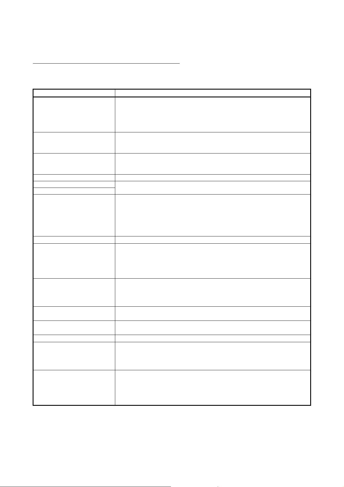
ABOUT MANUALS
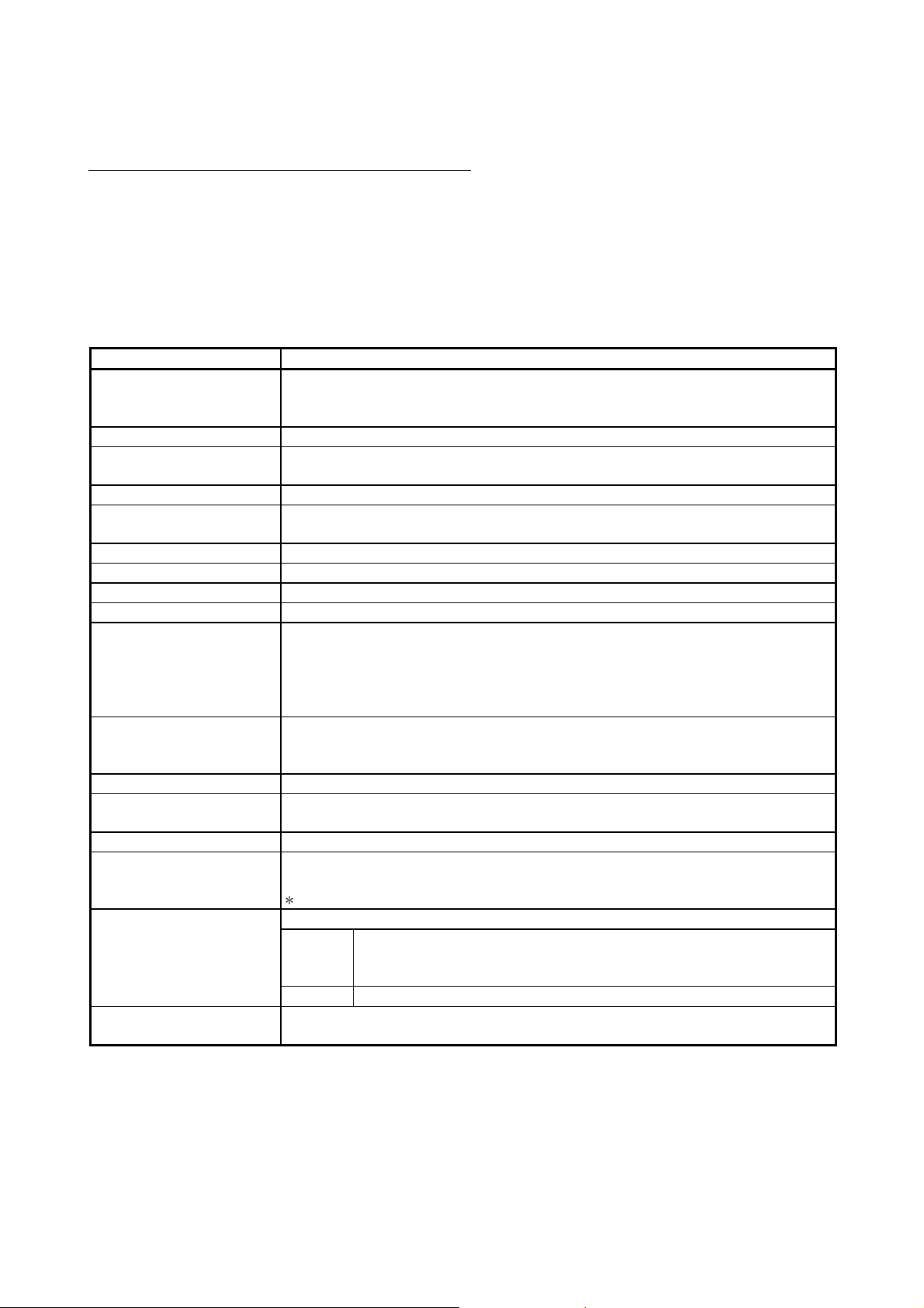
The following table lists the manuals relating to this product. Please order the desired manual(s) as needed.
Related manuals
Manual Name
MELSEC-Q/L Serial Communication Module User's Manual (Application)
Details of the special functions (specifications, usage, and settings) of the serial communication module
and the data communication methods between the module and external devices
(sold separately)
MELSEC Communication Protocol Reference Manual
Details of MELSEC communication protocol (MC protocol) that is used for data communication between
an external device and a CPU module
(sold separately)
GX Configurator-SC Version 2 Operating Manual (Protocol FB support function)
Details of the protocol FB support function (specifications, usage, and parameter settings) that enables
users to easily create data communication programs of the serial communication module
(sold separately)
Manual Number
(Model Code)
SH-080007
(13JL87)
SH-080008
(13JF89)
SH-080393E
(13JU46)
GX Configurator-SC Version 2 Operating Manual (Pre-defined protocol support function)
Details of the pre-defined protocol support function (specifications, usage, and protocol setting method)
of the serial communication module
(sold separately)
COMPLIANCE WITH THE EMC AND LOW VOLTAGE DIRECTIVES
(1) Method of ensuring compliance
To ensure that Mitsubishi programmable controllers maintain EMC and Low
Voltage Directives when incorporated into other machinery or equipment, certain
measures may be necessary. Please refer to one of the following manuals.
• QCPU User's Manual (Hardware Design, Maintenance and Inspection)
• Safety Guidelines
(This manual is included with the CPU module or base unit.)
The CE mark on the side of the programmable controller indicates compliance
with EMC and Low Voltage Directives.
(2) Additional measures
No additional measures are necessary for the compliance of this product with
EMC and Low Voltage Directives.
SH-080850ENG
(13JU66)
A - 16 A - 16

THE MANUAL'S USE AND STRUCTURE
How to use this manual
In this manual, details of the serial communication modules (QJ71C24N,
QJ71C24N-R2, QJ71C24N-R4, QJ71C24 and QJ71C24-R2) are organized as
shown below, according to their applications.
Please use this manual using the contents below as a reference.
(1) To learn about features, functions and component parts
(a) To learn about features and functions
• Chapter 1 describes the features of the serial communication modules.
• Chapter 3 describes the common specifications and functions of the serial
(b) To learn about the packed items and system-configured items
communication modules.
• The section prior to Chapter 1, "Product Configuration", describes the
parts that are packed along with the serial communication module.
• Parts and components other than those packed with the module must be
prepared separately by the user.
(2) To learn about processing required to start up the serial
communication module
(a) To learn about the startup procedure
• Section 4.2 describes the general procedures prior to starting the
(b) To learn about the connection with the external devices
(c) To learn about processing required prior to operation of the serial
(d) To check for failure in the serial communication module
(e) To learn how to check for a connection error with the external devices
operation of the serial communication module.
• Section 4.4 describes the connection methods for each type of interface.
communication module
• Section 4.5 explains the parameter settings with GX Developer in order to
use the serial communication module.
• Section 4.6 and Chapter 9 describe the settings from GX Configurator-SC
to perform the initial setting of the serial communication module.
To change an initial value, follow the procedure described in Chapter 9.
• Section 4.7 describes the test of the individual serial communication
module.
• Section 4.8 describes how to perform the individual module test and the
loopback test using MC protocol-based communication.
Details of the loopback test command are described in the reference
manual.
A - 17 A - 17

(3) To learn about data communication functions and detailed
explanations
(a) To learn about the communication functions
• Section 3.4 describes an overview of the serial communication module
(b) To learn about detailed explanations of the communication functions
functions.
• The basic communication methods are described in Chapters 5 to 7.
• Special functions are described in the User's Manual (Application).
(4) To learn about data communication functions and programming
(a) To learn how to read data from and written to the programmable controller
CPU
• Data is read from and written to the programmable controller CPU with a
communication function using the MC protocol.
Details are described in the Reference Manual.
• Appendix 7 describes an overview of the communication support tool (MX
(b) To learn how to send and receive data between the programmable controller
(c) To learn how to transfer data between a programmable controller CPU and
Component) that supports communication using the MC protocol.
CPU and the external devices
• Data communication between the programmable controller CPU and the
external devices is performed with a communication function using the
non procedure protocol or the bidirectional protocol.
• Chapter 6 explains details of the communication functions and
programming using the non procedure protocol.
• Chapter 7 explains details of the communication functions and
programming using the bidirectional protocol.
an external device using the protocol of the external device
• With the pre-defined protocol function, data can be transferred between
the QJ71C24N(-R2/R4) and external devices.
The details are described in the Operating Manual (Pre-defined protocol
support function).
(5) To learn how to check for error occurrences and take corrective
actions
Chapter 11 describes troubleshooting, how to check for errors, and detailed
explanations of error codes.
(6) To learn about functions that have been added or changed in
function version B
• Section 1.3 lists the functions that have been added or changed as well as
manuals that provide detailed explanations hereof.
• Appendix 1.1 provides a breakdown of the functions of Q series C24/GX
Configurator-SC by function version/software version.
A - 18 A - 18

The structure of this manual
The module's buffer memory stores default values that are used as initial settings
to execute the data send/receive functions in order to communicate with the
external devices.
Data can be sent to or received from the external devices using these default
values. However, it may be necessary to change the default values, depending on
system specifications.
This manual explains how to perform the initial settings in order to use each
function of the utility package available for this module (GX-Configurator-SC).
When changing a default value for sending and receiving data to/from an opposite
device, first see the section describing the applicable function to verify the initial
setting item and setting value you wish to change, then change the default value
as explained in Chapter 9.
A - 19 A - 19
ABOUT THE GENERIC TERMS AND ABBREVIATIONS
This manual uses the following generic terms and abbreviations to describe the serial communication
modules, unless otherwise specified.
(1) Generic terms and abbreviations of relevant modules
In this manual, the following generic terms and abbreviations are used to indicate
the programmable controller CPU and other modules used for the datacommunication functions of the serial communication modules. Module model
names are provided when relevant model names are needed to be shown.
Generic term/abbreviation Description of generic term/abbreviation
The abbreviation for QJ71C24N, QJ71C24N-R2, QJ71C24N-R4, QJ71C24 and QJ71C24-R2 type
Q series C24 (C24)
QC24 A generic term for AJ71QC24, AJ71QC24-R2, AJ71QC24-R4, A1SJ71QC24, and A1SJ71QC24-R2
QC24N
QC24(N) A generic term for QC24, and QC24N
QCPU
Basic model QCPU A generic term for Q00JCPU, Q00CPU, and Q01CPU
High Performance model QCPU A generic term for Q02CPU, Q02HCPU, Q06HCPU, Q12HCPU, and Q25HCPU
Process CPU A generic term for Q02PHCPU, Q06PHCPU, Q12PHCPU, and Q25PHCPU
Redundant CPU A generic term for Q12PRHCPU, and Q25PRHCPU
Universal model QCPU
Built-in Ethernet port QCPU
QCPU station The abbreviation for the programmable controller with QCPU installed
QnACPU
Q/QnACPU A generic term for QCPU, and QnACPU
UC24
Computer link module
Serial communication module
C Controller module
serial communication modules
(Indicated as "C24" in the diagrams)
A generic term for AJ71QC24N, AJ71QC24N-R2, AJ71QC24N-R4, A1SJ71QC24N1,
A1SJ71QC24N1-R2, A1SJ71QC24N, and A1SJ71QC24N-R2
A generic term for the Basic model QCPU, High Performance model QCPU, Process CPU,
Redundant CPU, and Universal model QCPU
A generic term for the Q00UJCPU, Q00UCPU, Q01UCPU, Q02UCPU, Q03UDCPU, Q03UDVCPU,
Q03UDECPU, Q04UDHCPU, Q04UDVCPU, Q04UDEHCPU, Q06UDHCPU, Q06UDVCPU,
Q06UDEHCPU, Q10UDHCPU, Q10UDEHCPU, Q13UDHCPU, Q13UDVCPU, Q13UDEHCPU,
Q20UDHCPU, Q20UDEHCPU, Q26UDHCPU, Q26UDVCPU, Q26UDEHCPU, Q50UDEHCPU, and
Q100UDEHCPU
A generic term for the Q03UDVCPU, Q03UDECPU, Q04UDVCPU, Q04UDEHCPU, Q06UDVCPU,
Q06UDEHCPU, Q10UDEHCPU, Q13UDVCPU, Q13UDEHCPU, Q20UDEHCPU, Q26UDVCPU,
Q26UDEHCPU, Q50UDEHCPU, and Q100UDEHCPU
A generic term for Q2ACPU, Q2ACPU-S1, Q2ASCPU, Q2ASCPU-S1, Q2ASHCPU, Q2ASHCPU-S1,
Q3ACPU, Q4ACPU, and Q4ARCPU
A generic term for AJ71UC24, A1SJ71UC24-R2, A1SJ71UC24-R4, A1SJ71UC24-PRF,
A1SJ71C24-R2, A1SJ71C24-R4, A1SJ71C24-PRF, A2CCPUC24, and A2CCPUC24-PRF
A series computer link modules.
A generic term for the module below
AJ71QC24, AJ71QC24-R2, AJ71QC24-R4, A1SJ71QC24, A1SJ71QC24-R2,
QnA series
Q series QJ71C24N, QJ71C24N-R2, QJ71C24N-R4, QJ71C24, QJ71C24-R2.
A generic term for the C Controller modules: Q06CCPU-V, Q06CCPU-V-B, Q12DCCPU-V,
Q24DHCCPU-V, and Q24DHCCPU-LS
AJ71QC24N, AJ71QC24N-R2, AJ71QC24N-R4, A1SJ71QC24N1, A1SJ71QC24N1-R2,
A1SJ71QC24N, A1SJ71QC24N-R2.
A - 20 A - 20
(2) Other generic terms and abbreviations
This manual uses the following generic terms and abbreviations to explain the
data-communication devices for the serial communication module. The
names/model names are provided when it is necessary to explicitly identify the
model being discussed.
Generic term/abbreviation Description of generic term/abbreviation
BIDIN The abbreviation for G.BIDIN or GP.BIDIN
BIDOUT The abbreviation for G.BIDOUT or GP.BIDOUT
A generic term for memory of the intelligent function modules/special function modules used for
Buffer memory
BUFRCVS The abbreviation for Z.BUFRCVS
CPRTCL The abbreviation for G.CPRTCL or GP.CPRTCL
CSET The abbreviation for ZP.CSET
Data communication function
GETE The abbreviation for G.GETE or GP.GETE
Intelligent function module devices
Intelligent function modules
MELSECNET/10 The abbreviation for MELSECNET/10 network system
MELSECNET/H The abbreviation for MELSECNET/H network system
ONDEMAND The abbreviation for G.ONDEMAND or GP.ONDEMAND
Operating Manual
(Protocol FB support function)
Operating Manual
(Pre-defined protocol support
function)
Opposite devices
(external devices)
OUTPUT The abbreviation for G.OUTPUT or GP.OUTPUT
PRR The abbreviation for G.PRR or GP.PRR
PUTE The abbreviation for G.PUTE or GP.PUTE
Reference Manual Q Corresponding MELSEC Communication Protocol Reference Manual
SPBUSY The abbreviation for G.SPBUSY or GP.SPBUSY
Special function modules
Switch setting A generic term for intelligent function module switch setting
UINI The abbreviation for ZP.UINI
User's Manual (Application) or
Application
User's Manual (Basic) or Basic Q Corresponding Serial Communication Module User's Manual (Basic)
A - 21 A - 21
storing data sent to or received from the programmable controller CPU. (setting values, monitor
values, etc.)
A generic term for MC protocol, non procedure protocol, and bidirectional protocol, and pre-defined
protocol
A generic term for buffer memory of the intelligent function modules used for storing data sent to or
received from the programmable controller CPU. (setting values, monitor values, etc.)
A generic term for the Q series programmable controller modules that are operated by commands
from the programmable controller CPU (equivalent to the A series programmable controller special
function modules)
Examples:
• CC-Link interface module
• A/D and D/A conversion modules
• Ethernet interface module
• Serial communication module
GX Configurator-SC Version 2 Operating Manual (Protocol FB support function)
GX Configurator-SC Version 2 Operating Manual (Pre-defined protocol support function)
A generic term for computers, indicators, measuring instruments, ID modules, bar code readers,
regulators, other serial communication modules, UC24, etc. that are connected to this serial
communication module for data communication
A generic term for the A/QnA series programmable controller modules that are operated by
commands from the programmable controller CPU (equivalent to the Q series programmable
controller intelligent function modules)
Examples:
• CC-Link interface module
• A/D and D/A conversion modules
• High-speed counter module
• Ethernet interface module
• Computer link module and serial communication module
MELSEC-Q/L Serial Communication Module User's Manual (Application)
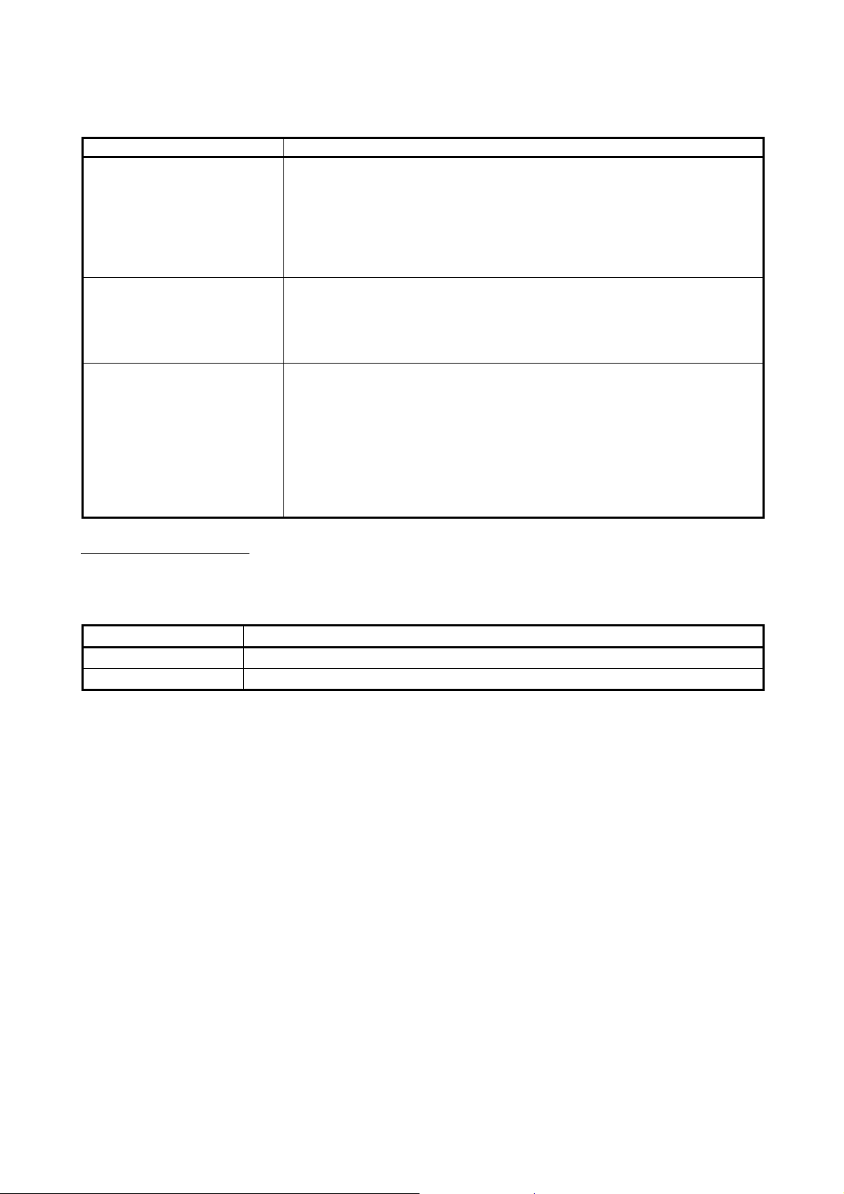
DEFINITIONS AND DESCRIPTIONS OF TERMINOLOGY
The following table lists the definitions and descriptions of terminology used in this manual and related
manuals for the Q series serial communication modules.
Terms Description
One of the message formats for the serial communication module for performing communication
A compatible 1C frame
(Formats 1 to 4)
Bidirectional protocol
Independent operation
GX Configurator-SC Setting and monitoring tool for the serial communication module (MELSOFT product)
GX Developer
GX Works2
Linked operation
MX Component Active X® control library for serial communication (MELSOFT product)
MELSEC communication protocol
(MC protocol)
Message send function
(Printer function)
Multidrop connection
Non procedure protocol
Packet A string of data used for communication with external devices by the pre-defined protocol.
Pre-defined protocol
Pre-defined protocol support function
using the MC protocol and ASCII code data.
This is the same message format as when communicating using the protocol for the A series
computer link modules. Device memory read/write operations for the QCPU are allowed within
the device range of the AnACPU.
A communication procedure for the serial communication modules and one of the data
communication functions for communicating any data between the programmable controller CPU
and an opposite device.
A mode of interface operation to communicate data with external devices using a function
specified in each communication protocol setting. Two interfaces of serial communication
modules do not interact.
The product name of the software package for the MELSEC programmable controllers
The operation mode of each of the two interfaces for a serial communication module that are
connected to external devices and linked to one another in order to send/receive data to/from the
external devices.
The two interfaces communicate data using the identical data-communication function (MC
protocol (identical format) or non procedure protocol) and the identical transmission
specifications. (Linked operation using the bidirectional or pre-defined protocol is not allowed.)
A communication procedure for the Q series serial communication modules or the Ethernet
interface modules, and a name of communication method for accessing to the programmable
controller CPU from an opposite device. (This is called the MC protocol in this manual.)
There are two communication methods; one uses ASCII code data and the other uses binary
code data.
This function registers character data (messages) to be sent to external devices (mainly printers)
in the serial communication module as a user frame in advance, and sends the registered data
for multiple user frames using the non-procedure protocol (sent by an instruction from the
programmable controller CPU).
A name of the connection when multiple external devices or other serial communication modules are
connected in a 1:n or m:n mode using the serial communication module's RS-422/485 interface.
A user's communication procedure and one of the data communication functions for
communicating any data between the programmable controller CPU and an opposite device.
One of the data communication functions available for the QJ71C24N(-R2/R4).
In data communication between the QJ71C24N(-R2/R4) and an external device, data can be
sent and received by using a protocol for the external device.
This must be set in GX Configurator-SC (Pre-defined protocol support function).
A function available in GX Configurator-SC (Pre-defined protocol support function), which
includes:
• Registration of the protocol appropriate to each external device
• Writing protocol setting data to or reading them from the flash ROM of the QJ71C24N(-R2/R4)
• Debug support function
A - 22 A - 22
Terms Description
QnA compatible 2C frame
(Formats 1 to 4)
QnA compatible 3C frame
(Formats 1 to 4)
QnA compatible 4C frame
(Formats 1 to 4)
QnA compatible 4C frame
(Format 5)
User frame
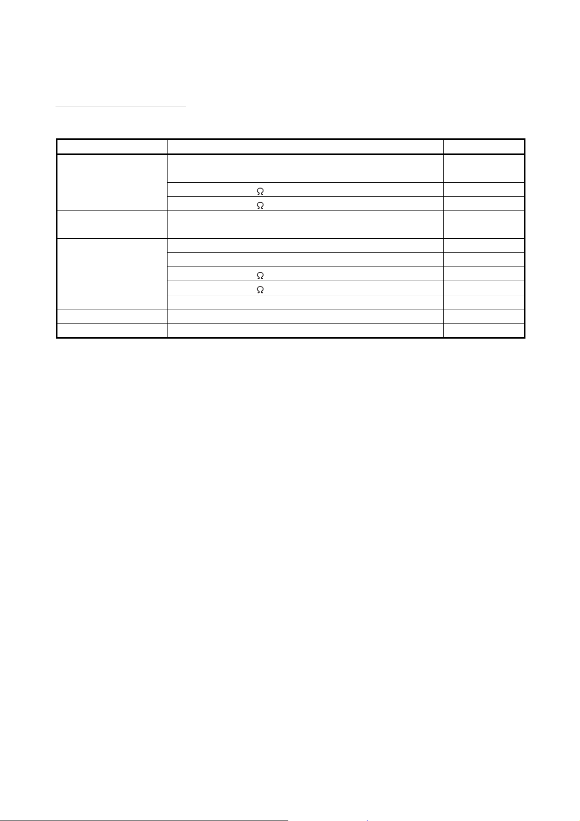
DISCONTINUED MODELS
One of the message formats for the serial communication module for performing communication
using the MC protocol and ASCII code data.
This is the same message format as the communication frame using the protocol for the QnA
series serial communication modules.
• QnA compatible 2C frame (Formats 1 to 4): QnA simplified frame (Formats 1 to 4)
• QnA compatible 3C frame (Formats 1 to 4): QnA frame (Formats 1 to 4)
• QnA compatible 4C frame (Formats 1 to 4): QnA extension frame (Formats 1 to 4)
One of the message formats for the serial communication module for performing communication
using the MC protocol and binary code data.
This is the same message format as the communication frame using the protocol for the QnA
series serial communication modules.
• QnA compatible 4C frame (Format 5): QnA extension frame (Format 5)
Data name when the fixed format portion of messages to be sent or received between a serial
communication module and an external device is registered in the module and used for sending
and receiving data. (The contents of a user frame data should conform to the specifications of the
external device.)
The data array of the head and tail sections of a message (transmission control code, serial
communication module station No., sum check, fixed data, etc.) to be sent and received is
registered in the serial communication module before use.
User frame is used in MC protocol on-demand functions and data communication functions which
use the non procedure protocol.
The following models are described in this manual, but have no longer been produced.
For the onerous repair term after discontinuation of production, refer to "WARRANTY" in this manual.
Model Production discontinuation
QJ71C24 January 2004
QJ71C24-R2 January 2004
A - 23 A - 23
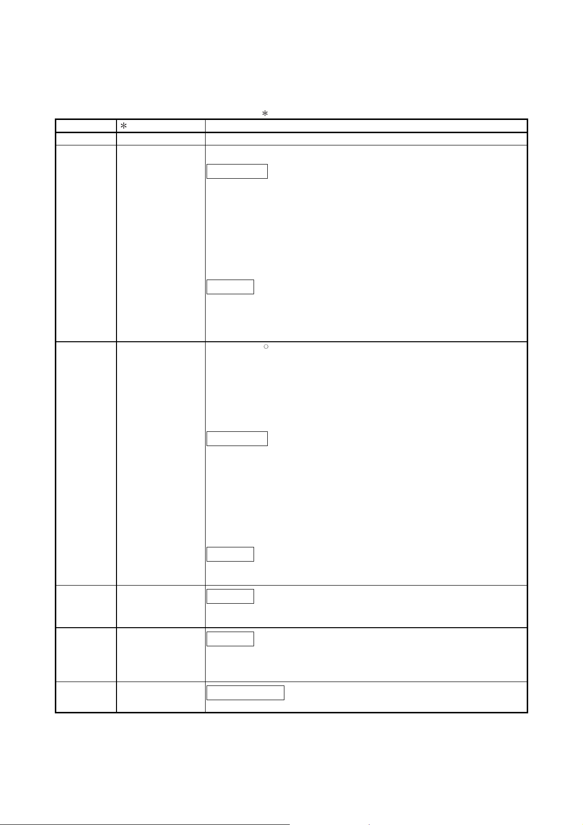
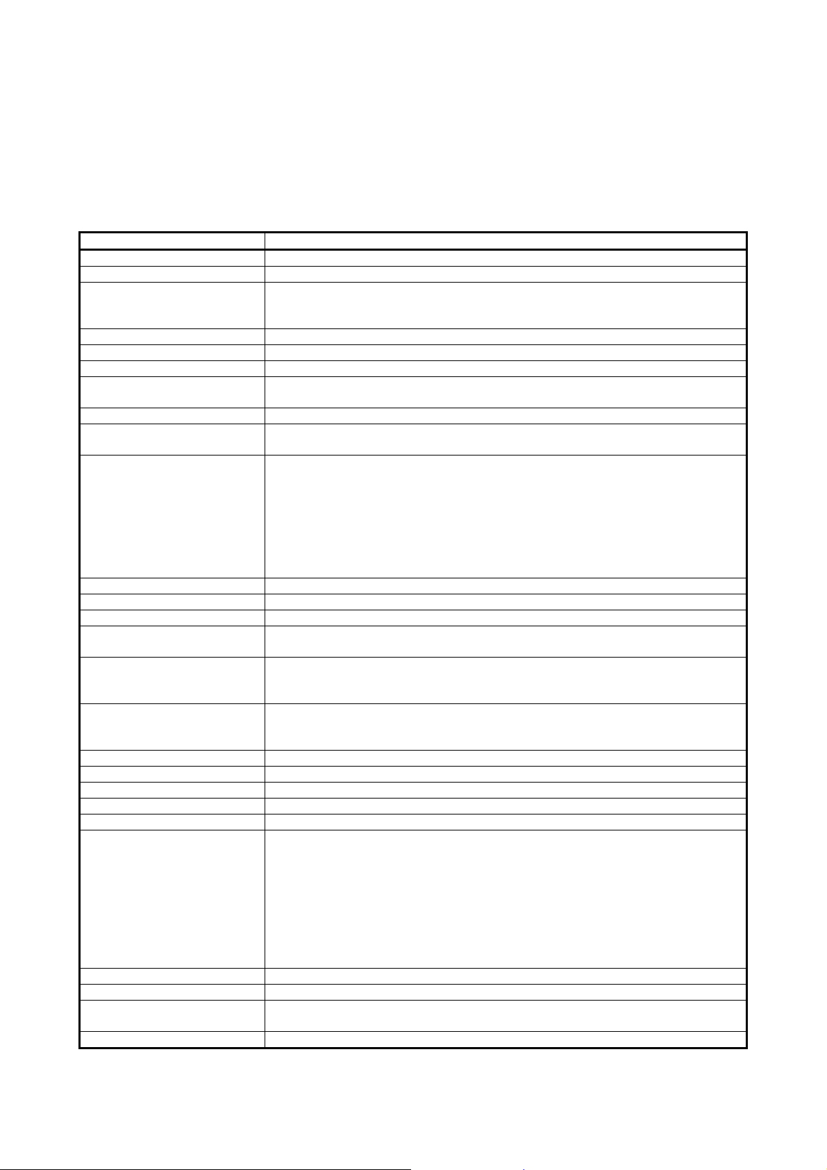
PRODUCT CONFIGURATION
The following lists the product configuration of the Q series serial communication modules.
Model Item name Quantity
QJ71C24N serial communication module or QJ71C24 serial
QJ71C24N or QJ71C24
QJ71C24N-R2 or
QJ71C24-R2
QJ71C24N-R4
SW2D5C-QSCU-E GX Configurator-SC Version 2 (1-license product) (CD-ROM) 1
SW2D5C-QSCU-EA GX Configurator-SC Version 2 (Multiple-license product) (CD-ROM) 1
communication module
Terminal resistor 330 ¼ W (for RS-422 communication) 2
Terminal resistor 110 ½ W (for RS-485 communication) 2
QJ71C24N-R2 serial communication module or QJ71C24-R2 serial
communication module
QJ71C24N-R4 serial communication module 1
RS-422/485 plug-in connector socket block 2
Terminal resistor 330 ¼ W (for RS-422 communication) 4
Terminal resistor 110 ½ W (for RS-485 communication) 4
Plate terminal (for connecting a braided shield cable) 4
1
1
A - 24 A - 24
1 OVERVIEW
MELSEC-Q
1 OVERVIEW
This manual describes the specifications for the QJ71C24N, QJ71C24N-R2,
QJ71C24N-R4, QJ71C24, QJ71C24-R2 serial communication module (hereinafter
referred to as "Q series C24"), as well as the procedures prior to starting the operation,
maintenance, inspection, data communication methods for use with external devices
and troubleshooting.
When applying the following program examples to the actual system, make sure to
examine the applicability and confirm that it will not cause system control problems.
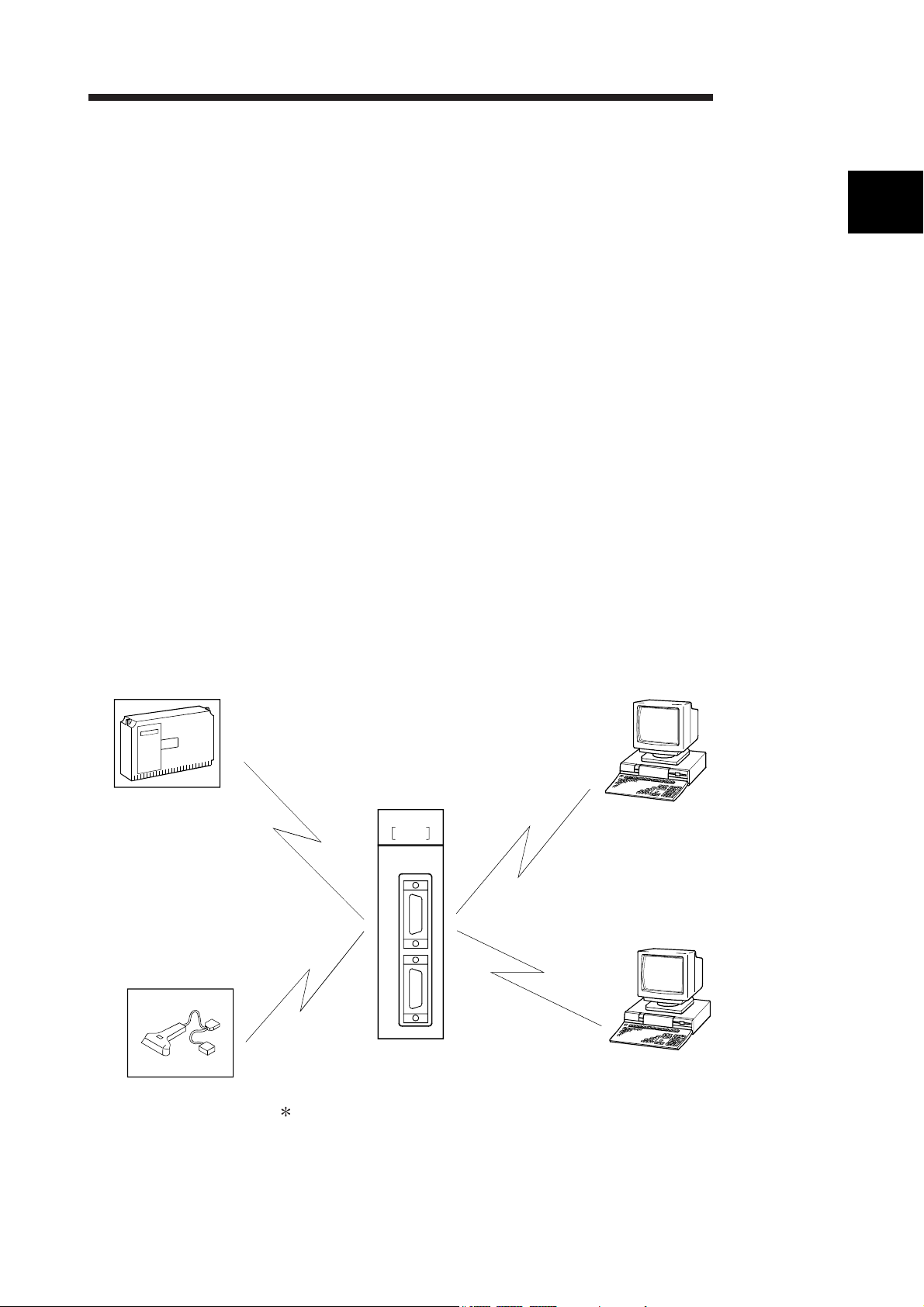
1.1 Overview of the Serial Communication Module
The Q series C24 is a module that connects the Q series programmable controller
CPU and an external device using an RS-232 or RS-422/485 line for serial
communication, in order to achieve the data communication described below.
By using a modem/terminal adapter, a public line (analog/digital) can be used for data
communication with a remote location.
• Programmable controller data collection/change from the external devices
(See the MELSEC Communication Protocol Reference Manual.)
• Programmable controller monitoring and control from the external devices (See the
User's Manual (Application).)
• Data receiving and sending in any formats that conform to the external device
specifications (See Section 1.2. (2), (3), and (4).)
• Collection of measured data from a measuring device (See Section 1.2. (2) and (4).)
• Operation of a programmable controller CPU that is connected to a personal
computer installed with GX Developer. (See the GX Developer Manual.)
1
• Collection of measured
data
• Collection of read data
QJ71C24-R2
RUN
ERR.
NEU
NEU
SD
SD
CH.1 CH.2
RD
RD
CH. 1
Being a convenient means of connection among different devices (personal
computers, display devices, printers, etc.), the serial communication line is the
most widely used medium on the market today.
• Programmable controller data
collection/change
• Programmable controller monitoring
and control from an external device
• Data receiving and sending in any
formats that conform to the external
device specifications
• GX Developer
• File writing/reading
• Device monitoring/testing
1 - 1 1 - 1
1 OVERVIEW
1.2 Features of the Serial Communication Module
The following describes the features of the Q series C24.
1
(1) Data communication based on the MELSEC communication
Q25HCPU
MELSEC
protocol (hereinafter referred to as the MC protocol)
(Details are explained in the MELSEC Communication Protocol Reference
Manual.)
(a) External devices can read/write the programmable controller device data
and sequence programs, and can monitor programmable controller
equipment status.
With the exception of the on-demand function described below, the
programmable controller does not require a sequence program because the
programmable controller sends and receives data based solely on
commands from external devices.
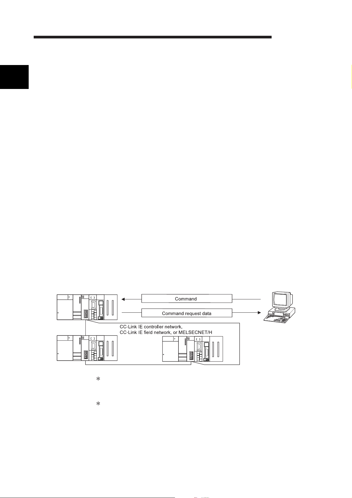
(b) Using the on-demand function, data can be sent from the programmable
controller CPU to the external devices in each frame format of the MC
protocol.
(c) Data communication can be performed using a program at the external
device side that has been created for communicating data with conventional
A/QnA series computer link module/serial communication modules.
(d) When an external device is a personal computer, use separately sold
communication support tools (MX Component). This allows a communication
program for the external device to be created, regardless of MC protocol's
transmitting/receiving procedure.
For details on MX Component, refer to Appendix 7 and the operating manual
of MX Component.
QJ71E71QJ71C24
MELSEC-Q
Q25HCPU
MELSEC
QJ71E71QJ71C24
Q25HCPU
MELSEC
QJ71E71QJ71C24
In the MELSECNET/H (MELSECNET/10 mode), other stations (including the
A/QnA series programmable controller CPUs) can be accessed during data link
operation.
The MC protocol is equivalent to the communication function using a dedicated
protocol that is supported by the A/QnA series computer link module/serial
communication modules.
1 - 2 1 - 2
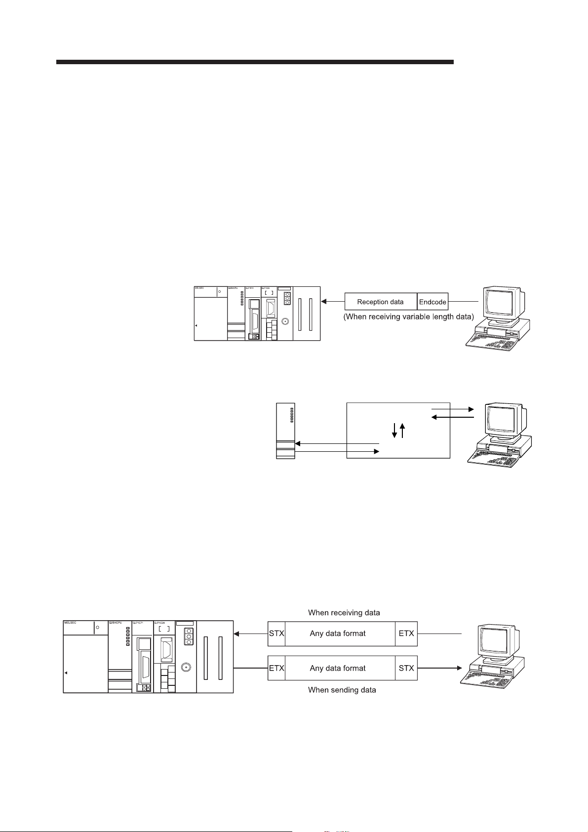
1 OVERVIEW
MELSEC-Q
(2) Data communication using the non procedure protocol
(Details are explained in Chapter 6 and the User's Manual (Application).)
(a) Data can be transferred in any message formats that conform to the
specifications of external devices (measuring devices, personal computers,
etc.).
(b) Fixed or variable length messages can be received in accordance with the
external device specifications.
• How to receive the variable length data
The external device sends data by adding at the end of the message the
end-code data (CR+LF or any one-byte data) that is set for the Q series C24.
• How to receive the fixed length data
The external device sends the amount of data equivalent to the size of the
end data that is set for the Q series C24.
(c) ASCII code data can be used for communication using the ASCII-BIN
conversion function.
QCPU
Q25HCPU
MODE
RUN
ERR.
USER
BAT.
BOOT
USB
RS-232
Binary
data
Q series C24
ASCII-BIN
conversion
Binary
data
ASCII
data
(d) It is necessary to create a sequence program for communication control that
is appropriate to the external device.
(e) Communication can be performed using a user frame by registering the fixed
format portion of the head and tail sections of a message as a user frame.
• When sending data, the Q series C24 adds a user frame to any data
specified by the user.
• When receiving data, the Q series C24 transfers any data excluding the
user frame to the programmable controller CPU.
(f) It is possible to clear the current reception data without interrupting the
transmission processing by using the dedicated instruction "CSET".
1 - 3 1 - 3
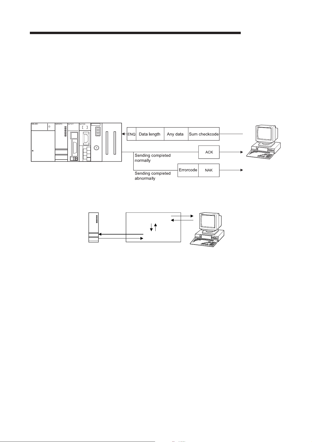
1 OVERVIEW
MELSEC-Q
(3) Data communication using the bidirectional protocol
(Details are explained in Chapter 7 and the User's Manual (Application).)
(a) In communication between programmable controller CPUs and
communication with an external device for which transmission/receive
control programming is allowed, data communication is performed in a
sequence of "data transmission and response receipt".
(b) Error check of received data can be performed using the sum-check code,
while the occurrence of a reception error at an external device can be
checked via an ACK/NAK response.
(c) ASCII code data can be used for communication using the ASCII-BIN
QCPU
Q25HCPU
RS-232
conversion function.
MODE
RUN
ERR.
USER
BAT.
BOOT
Binary
USB
data
Q series C24
ASCII-BIN
conversion
Binary
data
ASCII
data
1 - 4 1 - 4
 Loading...