

Mitsubishi Q, QD70P4, QD70, QD70P8, SW1D5C-QPTU-E User Manual
...
Type QD70 Positioning Module
U
Type QD70 Positioning Module User's Manual
Mitsubishi Programmable
Logic Controller
QD70P4
QD70P8
GX Configurator-PT
(SW1D5C-QPTU-E)
A - 1 A - 1
SAFETY INSTRUCTIONS
(Always read these instructions before using this equipment.)
Before using this product, please read this manual and the relevant manuals introduced in this manual
carefully and pay full attention to safety to handle the product correctly.
The instructions given in this manual are concerned with this product. For the safety instructions of the
programmable logic controller system, please read the CPU module User's Manual.
In this manual, the safety instructions are ranked as "DANGER" and "CAUTION".
!
DANGER
CAUTION
!
Indicates that incorrect handling may cause hazardous conditions,
resulting in death or severe injury .
Indicates that incorrect handling may cause hazardous conditions,
resulting in medium or slight personal injury or physical damage.
Note that the !CAUTION level may lead to a serious consequence according to the circumstances.
Always follow the instructions of both levels because they are important to personal safety.
Please save this manual to make it accessible when required and always forward it to the end user.
[DESIGN INSTRUCTION]
!
DANGER
Provide a safety circuit outside the programmable logic controller so that the entire system will
operate safely even when an external power supply error or PLC fault occurs.
Failure to observe this could lead to accidents for incorrect outputs or malfunctioning.
(1) Configure an emergency stop circuit and interlock circuit such as a positioning control
upper limit/lower limit to prevent mechanical damage outside the PLC.
(2) The OPR operation is controlled by the OPR direction and OPR speed data. Deceleration
starts when the near-point dog turns ON. Thus, if the OPR direction is incorrectly set,
deceleration will not start and the machine will continue to travel. Configure an interlock
circuit to prevent mechanical damage outside the PLC.
(3) When the module detects an error, deceleration st op will t ake place.
Make sure that the OPR data and positioning data are within the parameter setting values.
A - 2 A - 2
!
CAUTION
Do not bundle or adjacently lay the control wire or communication cable with the main circuit or
power wire.
Separate these by 100mm (3.94in.) or more.
Failure to observe this could lead to malfunctioning caused by noise.
[MOUNTING INSTRU CT ION S ]
!
CAUTION
Use the PLC within the general specifications environment given in t his manual.
Using the PLC outside the general specification range environment could lead t o elect ric
shocks, fires, malfunctioning, product damage or deterioration.
Hold down the module loading lever at the bottom of the module and insert the module fixing
hooks into the base unit fixing holes securely to load the module. Improper loading of the
module can cause a malfunction, failure or drop.
For use in vibratory environment, tighten the module with screws.
Tighten the screws within the specified torque range.
Undertightening can cause a drop, short circuit or malfunction.
Overtightening can cause a drop, short circuit or malfunction due to damage to the screws or
module.
Always load or unload the module after switching power off externally in all phases. Not doing
so may damage the product.
[WIRING INSTRUCTIONS]
!
DANGER
Always confirm the terminal layout before connecting the wires to the module.
[STARTUP/MAINTENANCE INSTRUCTIONS]
!
DANGER
Always turn all phases of the power supply OFF externally before cleaning or tightening the
screws.
Failure to turn all phases OFF could lead to electric shocks.

A - 3 A - 3
[STARTUP/MAINTENANCE INSTRUCTIONS]
!
CAUTION
Never disassemble or modify the module.
Failure to observe this could lead to trouble, malfunctioning, injuries or fires.
Always turn all phases of the power supply OFF externally before installing or removing the
module.
Failure to turn all phases OFF could lead to module trouble or malfunctioning.
Before starting test operation, set the parameter speed limit value to the slowest value, and
make sure that operation can be stopped immediately if a hazardous state occurs.
[DISPOSAL INSTRUCTIONS]
!
CAUTION
When disposing of the product, handle it as industrial waste.
A - 4 A - 4
REVISIONS
The manual number is given on the bottom left of the back cover
.
Print Date
Manual Number Revision
Jun., 2001 SH (NA)-080171-A First edition
Feb., 2002 SH (NA)-080171-B
Modifications
About Manuals, Section 2.3, Section 2.4, Section 4.6.1, Section 5.3,
Section 5.7, Section 6.2.2, Section 8.2.3, Section 8.2.4, Section
8.2.5, Section 8.2.6, Section 10.3, Appendix 8
Jul., 2002 SH (NA)-080171-C
Modifications
CONTENS, Section .1.1.1, Section 4.2, Section 11.3, Section 11.4,
Section 11.5, Section 13.2, Appendix 2, Appendix 8, INDEX
Japanese Manual Version SH-080138-D
This manual confers no industrial property rights or any rights of any other kind, nor does it confer any patent
licenses. Mitsubishi Electric Corporation cannot be held responsible for any problems involving industrial property
rights which may occur as a result of using the contents noted in this manual.
2001 MITSUBISHI ELECTRIC CORPORATION

A - 5 A - 5
INTRODUCTION
Thank you for purchasing the Mitsubishi programmable logic controller MELSEC-Q Series.
Always read through this manual, and fully comprehend the functions and performance of the Q Series PLC
before starting use to ensure correct usage of this product.
CONTENTS
SAFETY INSTRUCTIONS.............................................................................................................................A- 1
REVISIONS....................................................................................................................................................A- 4
CONTENTS....................................................................................................................................................A- 5
About Manuals ...............................................................................................................................................A- 9
Using This Manual..........................................................................................................................................A- 9
Conformation to the EMC Directive and Low Voltage Instruction ................................................................A- 9
Generic Terms and Abbreviations................................................................................................................A- 10
Component List .............................................................................................................................................A- 10
SECTION 1 PRODUCT SPECIFICATIONS AND HANDLING
1 PRODUCT OUTLINE 1- 1 to 1- 10
1.1 Positioning control....................................................................................................................................1- 1
1.1.1 Features of QD70..............................................................................................................................1- 1
1.1.2 Mechanism of positioning control ......................................................................................... ............1- 2
1.1.3 Outline design of positioning control system....................................................................................1- 4
1.1.4 Communicating signals between QD70 and each module..............................................................1- 7
1.2 Positioning control....................................................................................................................................1- 9
1.2.1 Outline of starting ...................................................................................................... ........................1- 9
1.2.2 Outline of stopping ...........................................................................................................................1- 10
2 SYSTEM CONFIGURATION 2- 1 to 2- 5
2.1 General image of system.........................................................................................................................2- 1
2.2 Component list .........................................................................................................................................2- 2
2.3 Applicable system....................................................................................................................................2- 3
2.4 How to check the function version and the software version ................................................................. 2- 4
3 SPECIFICATIONS AND FUNCTIONS 3- 1 to 3- 11
3.1 Performance specifications......................................................................................................................3- 1
3.2 List of functions ........................................................................................................................................3- 2
3.3 Specifications of input/output signal with PLC CPU ...............................................................................3- 4
3.3.1 List of input/output signals with PLC CPU........................................................................................3- 4
3.3.2 Details of input signal (QD70
PLC CPU) .....................................................................................3- 5
3.3.3 Details of output signals (PLC CPU
QD70).................................................................................3- 6
3.4 Specifications of input/output interfaces with external device ................................................................3- 7
3.4.1 Electrical specifications of input/output signals................................................................................ 3- 7
3.4.2 Signal layout for external device connection connector...................................................................3- 9
3.4.3 List of input/output signal details......................................................................................................3- 10
3.4.4 Input/output interface internal circuit................................................................................................3- 11

A - 6 A - 6
4 DATA USED FOR POSITIONI NG CON TROL ( LIS T OF BU FFER MEM ORY ADDRE SSES ) 4- 1 to 4- 31
4.1 Type of data .............................................................................................................................................4- 1
4.1.1 Parameters and data required for control.........................................................................................4- 1
4.1.2 Setting items for parameters.............................................................................................................4- 3
4.1.3 Setting items for OPR data...............................................................................................................4- 4
4.1.4 Setting items for JOG data................................................................................................................4- 5
4.1.5 Setting items for positioning data...................................................................................................... 4- 6
4.1.6 Type and roles of monitor data.........................................................................................................4- 7
4.1.7 Type and roles of control data ..........................................................................................................4- 8
4.2 List of parameters ....................................................................................................................................4- 9
4.3 List of OPR data......................................................................................................................................4- 14
4.4 List of JOG data ......................................................................................................................................4- 20
4.5 List of positioning data ............................................................................................................................4- 21
4.6 List of monitor data..................................................................................................................................4- 27
4.6.1 Axis monitor data..............................................................................................................................4- 27
4.6.2 Module information monitor data.....................................................................................................4- 29
4.7 List of control data...................................................................................................................................4- 30
4.7.1 Axis control data...............................................................................................................................4- 30
5 SETUP AND PROCEDURES BEFORE OPERATION 5- 1 to 5- 20
5.1 Handling precautions ...............................................................................................................................5- 1
5.2 Procedures before operation ...................................................................................................................5- 3
5.3 Part identification nomenclature ..............................................................................................................5- 4
5.4 Wiring .......................................................................................................................................................5- 7
5.4.1 Wiring precautions.............................................................................................................................5- 7
5.5 Confirming the wiring ..............................................................................................................................5- 12
5.5.1 Confirmation items at completion of wiring......................................................................................5- 12
5.6 Switch setting for intelligent function module.........................................................................................5- 14
5.7 Simple reciprocating operation...............................................................................................................5- 18
6 UTILITY PACKAGE(GX Configurator-PT) 6- 1 to 6- 17
6.1 Utility package functions .......................................................................................................................... 6- 1
6.2 Installing and uninstalling the utility package..........................................................................................6- 2
6.2.1 User precautions ...............................................................................................................................6- 2
6.2.2 Operating environment......................................................................................................................6- 4
6.3 Explanation of utility package operations................................................................................................6- 5
6.3.1 How to perform common utility package operations........................................................................ 6- 5
6.3.2 Operation overview ...........................................................................................................................6- 7
6.3.3 Starting the intelligent function module utility ................................................................................... 6- 9
6.4 Initial setting.............................................................................................................................................6- 11
6.5 Auto refresh setting.................................................................................................................................6- 13
6.6 Monitor/test..............................................................................................................................................6- 15
6.6.1 Monitor/Test screen..........................................................................................................................6- 15
7 SEQUENCE PROGRAM USED FOR POSITIONING CONTROL 7- 1 to 7- 20
7.1 Precautions for creating program............................................................................................................7- 1
7.2 List of devices used..................................................................................................................................7- 3

A - 7 A - 7
7.3 Creating a program ..................................................................................................................................7- 5
7.3.1 General configuration of program.....................................................................................................7- 5
7.3.2 Positioning control operation program..............................................................................................7- 6
7.4 Positioning control program examples....................................................................................................7- 8
7.5 Program details.......................................................................................................................................7- 12
7.5.1 Initialization program ........................................................................................................................7- 12
7.5.2 Start method setting program ..........................................................................................................7- 13
7.5.3 Start program....................................................................................................................................7- 13
7.5.4 Sub program.....................................................................................................................................7- 18
SECTION 2 CONTROL DETAILS AND SETTING
8 OPR CONTROL 8- 1 to 8- 16
8.1 Outline of OPR control.............................................................................................................................8- 1
8.1.1 Two types of OPR control.................................................................................................................8- 1
8.2 Machine OPR control...............................................................................................................................8- 2
8.2.1 Outline of the machine OPR operation.............................................................................................8- 2
8.2.2 Machine OPR method.......................................................................................................................8- 3
8.2.3 OPR method (1): Near-point dog method ........................................................................................8- 4
8.2.4 OPR method (2): Stopper 1 .............................................................................................................. 8- 6
8.2.5 OPR method (3): Stopper 2 .............................................................................................................. 8- 8
8.2.6 OPR method (4): Stopper 3 .............................................................................................................8- 10
8.2.7 OPR method (5): Count 1 ................................................................................................................8- 12
8.2.8 OPR method (6): Count 2 ................................................................................................................8- 14
8.3 Fast OPR control.....................................................................................................................................8- 16
8.3.1 Outline of the fast OPR control operation........................................................................................8- 16
9 POSITIONING CONTROL 9- 1 to 9- 17
9.1 Outline of positioning controls..................................................................................................................9- 1
9.1.1 Data required for positioning control.................................................................................................9- 1
9.1.2 Operation patterns of positioning controls........................................................................................9- 2
9.1.3 Designating the positioning address.................................................................................................9- 8
9.1.4 Confirming the current value.............................................................................................................9- 9
9.2 Setting the positioning data ....................................................................................................................9- 10
9.2.1 Relation between each control and positioning data ......................................................................9- 10
9.2.2 1-axis linear control ..........................................................................................................................9- 11
9.2.3 Speed-position switching control ..................................................................................................... 9- 13
9.2.4 Current value changing....................................................................................................................9- 16
9.3 Multiple axes simultaneous start control ................................................................................................9- 17
10 JOG OPERATION 10- 1 to 10- 6
10.1 Outline of JOG operation.....................................................................................................................10- 1
10.2 JOG operation execution procedure ...................................................................................................10- 3
10.3 JOG operation example.......................................................................................................................10- 4
11 SUB FUNCTIONS 11- 1 to 11- 13
11.1 Outline of sub functions .......................................................................................................................11- 1
A - 8 A - 8
11.2 Speed limit function..............................................................................................................................11- 1
11.3 Speed change function........................................................................................................................11- 2
11.4 Software stroke limit function...............................................................................................................11- 5
11.5 Acceleration/deceleration processing function....................................................................................11- 8
11.6 Restart function...................................................................................................................................11- 12
12 COMMON FUNCTIONS 12- 1 to 12- 3
12.1 Outline of common functions ...............................................................................................................12- 1
12.2 External I/O signal switching function..................................................................................................12- 1
12.3 External I/O signal monitor function ....................................................................................................12- 2
13 TROUBLESHOOTING 13- 1 to 13- 14
13.1 Error and warning details.....................................................................................................................13- 1
13.2 List of errors .........................................................................................................................................13- 3
13.3 List of warnings ...................................................................................................................................13- 11
13.4 LED display function...........................................................................................................................13- 13
13.5 Confirming the error definition using system monitor of GX Developer............................................13- 14
APPENDIX App- 1 to App- 18
Appendix 1 External dimension drawing ...................................................................................................App- 1
Appendix 2 Operation timing and processing time in each control ..........................................................App- 2
Appendix 3 Connection examples with servo amplifiers manufactured by MITSUBISHI Electric Corporation
.................................................................................................................................................App- 6
Appendix 3.1 Connection example of QD70P
and MR-H A...........................................................App- 6
Appendix 3.2 Connection example of QD70P
and MR-J2/J2S- A................................................App- 7
Appendix 3.3 Connection example of QD70P
and MR-C A...........................................................App- 8
Appendix 4 Connection examples with stepping motors manufactured by ORIENTALMOTOR Co., Ltd.
.................................................................................................................................................App- 9
Appendix 4.1 Connection example of QD70P
and VEXTA UPD .....................................................App- 9
Appendix 5 Connection examples with servo amplifiers manufactured by Matsushita Electric Industrial Co.,
Ltd...........................................................................................................................................App- 10
Appendix 5.1 Connection example of QD70P
and MINAS A series ...............................................App- 10
Appendix 6 Connection examples with servo amplifiers manufactured by Yamayo Electric Co., Ltd...App- 11
Appendix 6.1 Connection example of QD70P
and PZ series..........................................................App- 11
Appendix 7 Connection examples with servo amplifiers manufactured by Yasukawa Electric Co., Ltd
................................................................................................................................................App- 12
Appendix 7.1 Connection example of QD70P
and Σ- series .........................................................App- 12
Appendix 8 Comparisons with type QD75 positioning module................................................................App- 13
Appendix 9 List of buffer memory addresses...........................................................................................App- 16
INDEX Index- 1 to Index- 5

A - 9 A - 9
About Manuals
The following manuals are also related to this product.
In necessary, order them by quoting the details in the tables below.
Detailed Manuals
Manual Name
Manual Number
(Model Code)
Type QD70 Positioning Module User's Manual (Hardware)
Describes the performance, specifications, I/O interface, component names, and startup procedure of
the respective positioning modules: QD70P4 and QD70P8. (The manual is supplied with the module.)
IB-0800169
(13JT42)
Using This Manual
The symbols used in this manual are shown below.
Pr.
...... Symbol indicating positioning parameter and OPR parameter item.
OPR.
....... Symbol indicating OPR data item.
JOG.
....... Symbol indicating JOG data item.
Da.
...... Symbol indicating positioning data item.
Md.
...... Symbol indicating monitor data item.
Cd.
....... Symbol indicating control data item.
(A serial No. is inserted in the
mark. )
Numeric values used in this manual
• The buffer memory addresses, error codes and warning codes are represented
in decimal.
• The X/Y devices are represented in hexadecimal.
• The setting data and monitor data are represented in either decimal or
hexadecimal. The data ended b y "H" are repres en ted in hex a dec imal.
(Example) 10.........10 Decimal
10H......16 Hexadecimal
Conformation to the EMC Directive and Low Voltage Instruction
For details on making Mitsubishi PLC conform to the EMC directive and low
voltage instruction when installing it in your product, please refer to Chapter 3,
“EMC Directive and Low Voltage Instruction” of the using PLC CPU module
User’s Manual (Hardware).
The CE logo is printed on the rating plate on the main body of the PLC that
conforms to the EMC directive and low voltage instruction.
To make this product conform to the EMC directive and low voltage instruction,
please refer to Section 5.4.1 "Wiring precautions".
A - 10 A - 10
Generic Terms and Abbreviations
Unless specially noted, the following generic terms and abbreviations are used in
this manual.
Generic term/abbreviation Details of generic term/abbreviation
PLC CPU Generic term for PLC CPU on which QD70 can be mounted.
AD75 Generic term for type A1SD75P1-S3/P2-S3/P3-S3, AD75P1-S3/P2-S3/P3-S3 Positioning
module.
The module type is described to indicate a specific modul e.
QD70 Generic term for type QD70 positioning module QD70P4/QD70P8.
The module type is described to indicate a specific modul e.
QD75
Generic term for positioning module QD75P1, QD75P2, QD75P4, QD75D1, QD 75D2, and
QD75D4.
The module type is described to indicate a specific modul e.
Peripheral device
Generic term for DOS/V personal computer where following "GX Configurator-PT" and ""GX
Developer" have been installed.
GX Configurator-PT
Abbreviation for GX Configurator-PT (SW1D5C-QPTU-E) utility package for QD70 positioning
module.
GX Developer Abbreviation for GX Developer (SW4D5C-GPPW-E or later).
Drive unit
Abbreviation for open collector pulse input compatible drive unit (servo amplifier or stepping
motor).
DOS/V personal computer IBM PC/AT® and compatible DOS/V compliant personal computer.
Personal computer Generic term for DOS/V personal computer.
Workpiece Generic term for moving body such as workpiece and tool, and for v arious control targ ets.
Axis 1, axis 2, axis 3,
axis 4, axis 5, axis 6,
axis 7, axis 8
Indicates each axis connected to QD70.
1-axis, 2-axes, 3-axes,
4-axes, 5-axes, 6-axes,
7-axes, 8-axes
Indicates the number of axes. (Example: 2-axes = Indicates two axes such as axis 1 and axis
2, axis 2 and axis 3, and axis 3 and axis 1.)
Component List
The component list of this product is given below.
Type Component Quantity
QD70P4 Type QD70P4 Positioning Module (4-axes open-collector output type) 1
QD70P8 Type QD70P8 Positioning Module (8-axes open-collector output type) 1
SW1D5C-QPTU-E GX Configurator-PT Version 1 (1-license product) (CD-ROM) 1
SW1D5C-QPTU-EA GX Configurator-PT Version 1 (Multiple-license product) (CD-ROM) 1

SECTION 1 PRODUCT SPECIFICATIONS
AND HANDLING
Section 1 is configured for the following purposes (1) to (4).
(1) To understand the outline of positioning control, and the QD70 specifications
and functions
(2) To carry out actual work such as installation and wiring
(3) To set parameters and data required for positioning control
(4) To create a sequence program required for positioning control
Read "Section 2" for details on each control.
CHAPTER 1 PRODUCT OUTLINE ................................................................................. 1- 1 to 1- 10
CHAPTER 2 SYSTEM CONFIGURATION..................................................................... 2- 1 to 2- 5
CHAPTER 3 SPECIFICATIONS AND FUNCTIONS...................................................... 3- 1 to 3- 11
CHAPTER 4 DATA USED FOR POSITIONING CONTROL.......................................... 4- 1 to 4- 31
CHAPTER 5 SETUP AND PROCEDURES BEFORE OPERATION............................. 5- 1 to 5- 20
CHAPTER 6 UTILITY PACKAGE.................................................................................... 6- 1 to 6- 17
CHAPTER 7 SEQUENCE PROGRAM USED FOR POSITIONING CONTROL........... 7- 1 to 7- 20
SECTION 1

MEMO
SECTION 1

1 - 1 1 - 1
MELSEC-Q
1 PRODUCT OUTLINE
CHAPTER 1 PRODUCT OUTLINE
This user's manual provides the specifications, handling, programming methods and
other information of the QD70 positioning module used with the MELSEC-Q series
CPU module.
1.1 Positioning control
1.1.1 Features of QD70
The following are the features of the QD70.
(1) Wide assortment of 4-axes and 8-ax es modul es
The QD70 is a positioning module used in a multi-axes system that does not
need complex control.
It is not compatible with the MELSEC-A series AD70 positioning module in I/O
signals, functio n s, et c.
(2) About positioning control functions
(a) The QD70 has a number of functions required for a positioning control
system, such as posi ti oni ng cont r ol to any po sit io n an d equa l - spee d contr ol .
1) You can set up to 10 pieces of positioning data, which include
positioning address, control method, operation pattern and like, per axis.
These positioning data are used to exercise positioning control axis-byaxis.
2) Axis-by-axis positioning control allows linear control (up to 8 axes can be
controlled simul tane ou sly ) .
This control can perform positioning termination with one piece of
positioning data or exercise continuous positioning control by continuous
execution of multi pl e pi e ces of po sit ion in g da ta.
(b) As the control method, any of position control, speed-position switching
control and current value changing may be specified in each positioning
data.
(c) The following six different OPR methods are available for "machine OPR
control": nea r-p oi nt do g meth od (o ne met h od ), stop pe r (t hree met h od s) an d
count (two methods).
(d) Varying finely in speed to ensure smooth acceleration/deceleration, the
QD70 is suitable fo r co nne ctio n t o a st epping motor.
(e) You can change the I/O signal logic according to the specifications of the
external device.
This allows the input signals to be used with either of "normally open" and
"normally closed" contacts, and the output signals to be used according to
the specifications of the drive unit.
(3) Fast start processing
Processing at a position control start has been speeded up to shorten the start
processing time of one axis to 0.1ms.
At a simultaneous start of multiple axes (the positioning start signals are turned
ON at the same time within one scan), there are no starting delays between the
axes.
(4) Ease of maintenance
In the QD70, error definitions have been subdivided to improve maintenance
performance.
(5) Ease of utility package settings
The optionally available utility package (GX Configurator-PT) allows initial setting
and auto refresh setting to be made on the screen, reducing sequence programs
and facilitating the confirmation of the setting status and operating status.
1
1 - 2 1 - 2
MELSEC-Q
1 PRODUCT OUTLINE
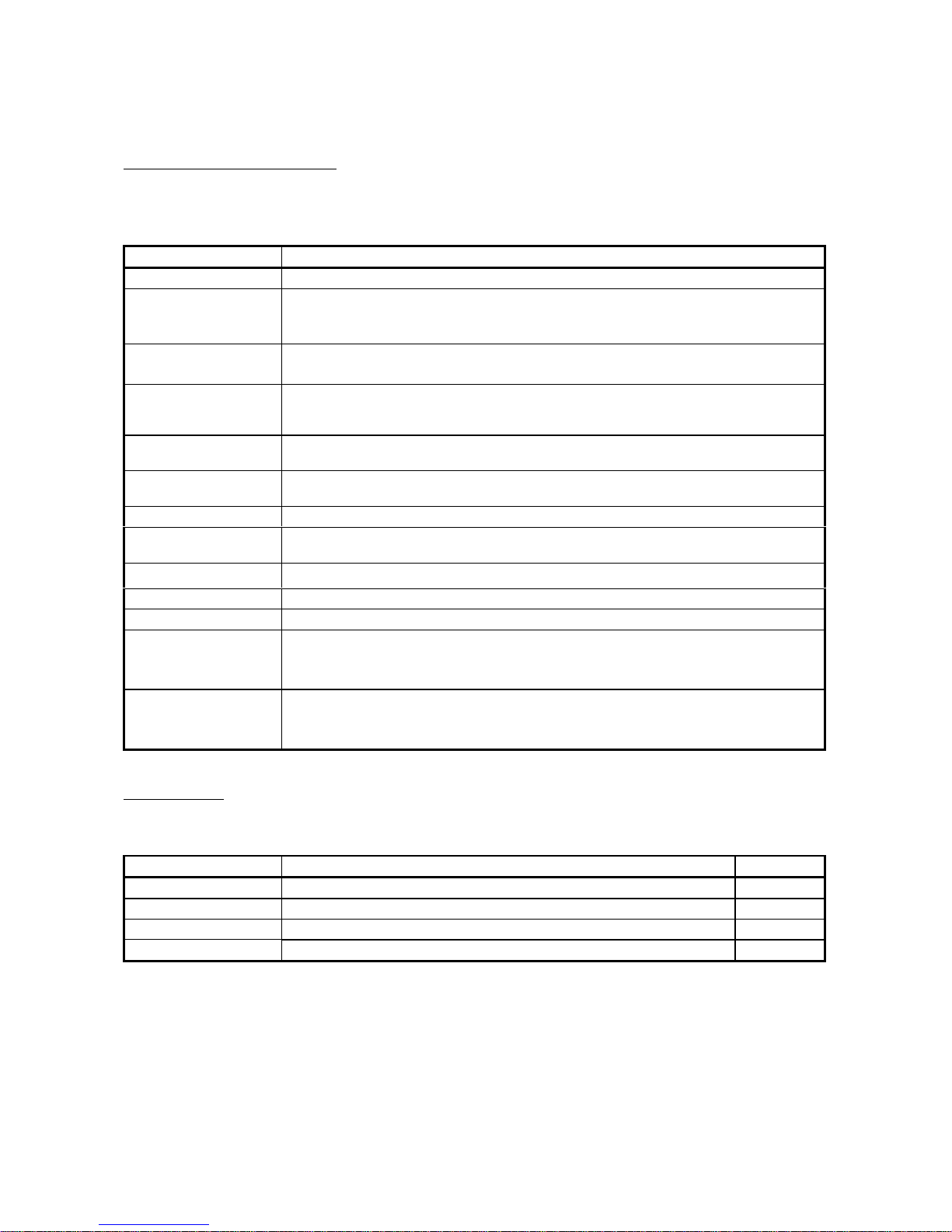
1.1.2 Mechanism of positioning control
Positioning control using the QD70 is exercised using "pulse signals". (The QD70 is a
module that outputs pulses.)
In a positioning control system using the QD70, a variety of software and external
devices are used to play their roles as shown below.
The QD70 imports various signals, parameters and data, and exercises control with
the PLC CPU to realiz e co mpl e x po siti oni ng con tro l.
Stores the created program.
The QD70 outputs the positioning start signal and
axis stop signal following the stired program.
QD70 errors, etc., are detected.
PLC CPU
Peripheral device
GX Developer/
GX Configurator-PT
QD70
positioning
module
Drive
unit
Stores the parameter and data
Outputs to the drive unit according to the
instructins from the PLC CPU.
Receives pulses commands from QD70,
and drives the motor.
Carries out the actual work according to
commands from the drive unit
Motor
Workpiece
Using GX Developer, create
control sequence and conditions
as sequence program.
Adding in GX Configurator-PT
enables initial setting of
parameters and data.
Input near-point dog signal and speed
-position switching signal to QD70.
Mechanical
system inputs
(Switches)
1
1 - 3 1 - 3
MELSEC-Q
1 PRODUCT OUTLINE
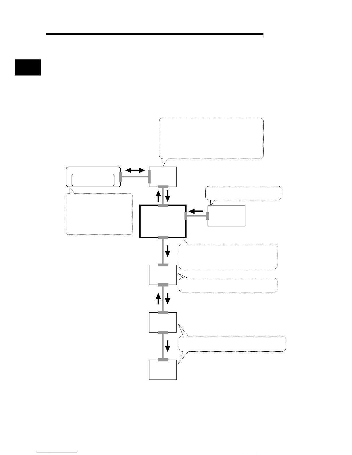
The principle of "position control" and "speed control" operation is shown below.
Position control
The total No. of pulses required to move the designated distance is obtained in the
following manner.
Total No. of pulses
required to move
designated distance
Designated distance
Movement amount of machine (load)
side when motor rotates once
No. of pulses
required for motor to
rotate once
=
The No. of pulses required for the motor to rotate once is the "encoder resolution"
described in the motor catalog specification list.
When this total No. of pulses is issued from the QD70 to the drive unit, control to move
the designated distance can be executed.
The machine side movement amount when one pulse is issued to the drive unit is
called the "movement amount per pulse". This value is the min. value for the workpiece
to move, and is also the electrical positioning control precision.
Speed control
Though the above "total No. of pulses" is an element needed to control the
movement amount, speed must be controlled to perform equal-speed operation.
This "speed" is controlled by the "pulse frequency" output from the QD70 to the drive
unit.
Speed=Pulses frequency
Movement amount=No. of puleses
Feedback pulses=
Pulses generated by detector
Positioning
module
Servo
amplifiter
Servo
motor
Detector
Pulses generated by detector
A
ta td
0.4 0.41.2
(s)
Pulse frequency
[pps]
This area is hte total
No. of commanded
pulses.
Movement amount t = 2
Fig. 1.1 Relationship between position control and speed control
POINT
• The "movement amount per pulse" is the value determined on the machine side.
(Refer to Section 1.1.3.)
• The QD70 uses the "total No. of pulses" to control the position, and uses the
"pulse frequency" to control the speed.
1 - 4 1 - 4
MELSEC-Q
1 PRODUCT OUTLINE
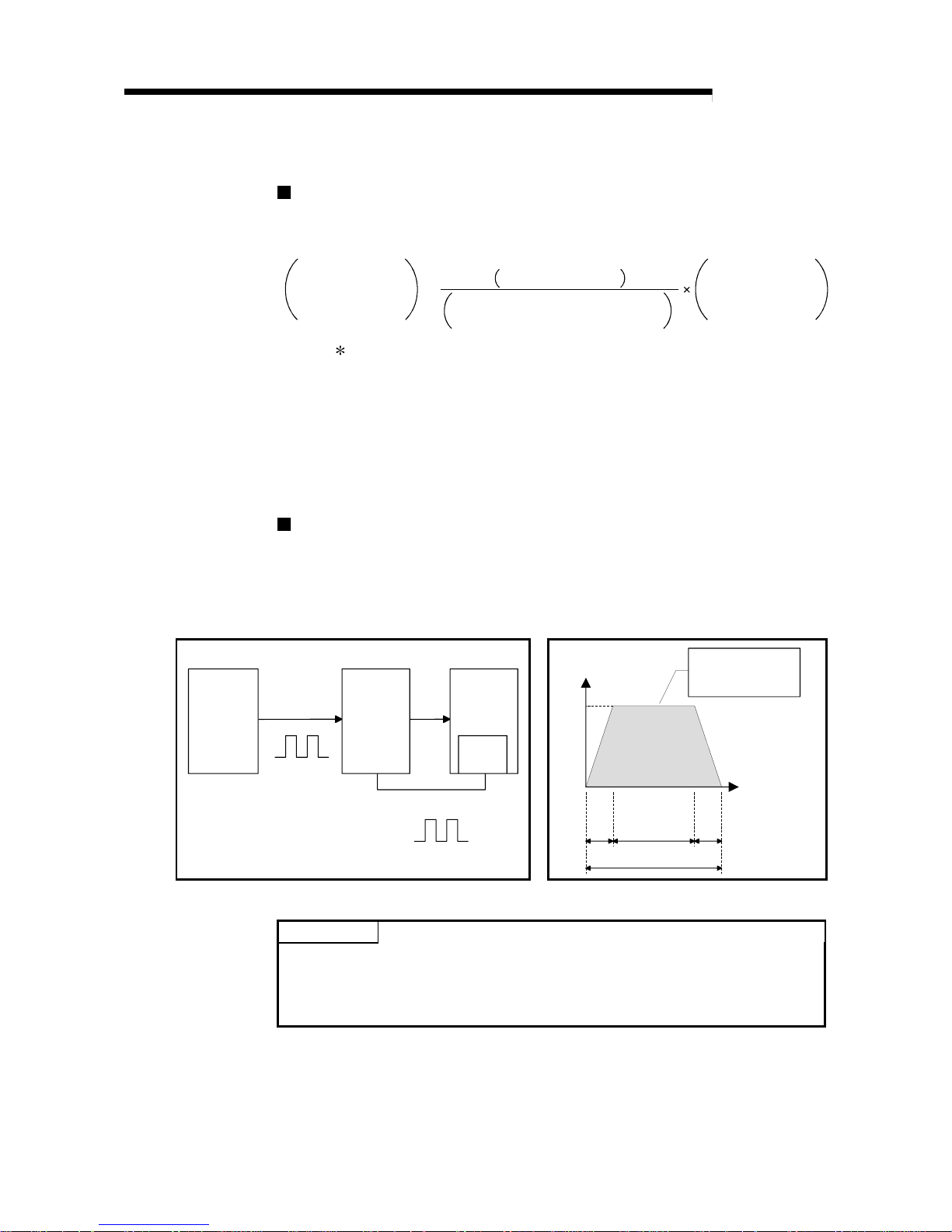
1.1.3 Outline design of positioning control sy stem
The outline of the positioning control system operation and design, using the QD70, is
shown below.
(1) Positioning control system using QD70
Positioning module
QD70
PLC CPU
M
PG
GX Configurator-PT
Program
Intelligent
function module
parameter
Read, write, etc.
Monitor date read
Initial setteng /Auto rofresh setting/Monitor
Drive unit
Buffer
memories
/XY
device
Forward run
pulse train
Reverse run
pulse train
Deviation
counter
D/A
converter
Speed
command
Servo
amplifiter
Interface
Feedback pulse
Servomotor
Fig. 1.2 Outline of the operation of positioning control system using QD70
(a) Positioning operation by the QD70
1) The QD70 output is a pulse train.
The pulse train output by the QD70 is counted by and stored in the
deviation counter in the drive unit.
The D/A converter outputs an analog DC current proportionate to the
count maintained by the deviation counter (called "pulse droop"). The
analog DC current serves as the servo motor speed control signal.
2) The servo motor rotation is controlled by the speed control signal from
the drive unit.
As the servo motor rotates, the pulse generator (PG) attached to the
servo motor generates feedback pulses, the frequency of which is
proportionate to the rotation speed.
The feedback pulses are fed back to the drive unit and decrements the
pulse droop, the pulse count maintained by the deviation counter.
The motor keeps on rotating as the pulse droop is maintained at a
certain level.
3) When the QD70 terminates the output of a pulse train, the servo motor
decelerates as the pulse droop decreases and stops when the count
drops to zero.
Thus, the servo motor rotation speed is proportionate to the pulse
frequency, while the overall motor rotation angle is proportionate to the
total number o f pu l ses ou tp ut by the QD70.
Therefore, when a movement amount per pulse is given, the overall
movement amount can be determined by the number of pulses in the
pulse train.
The pulse frequency, on the other hand, determines the servo motor
rotation speed (feed speed).
1 - 5 1 - 5
MELSEC-Q
1 PRODUCT OUTLINE
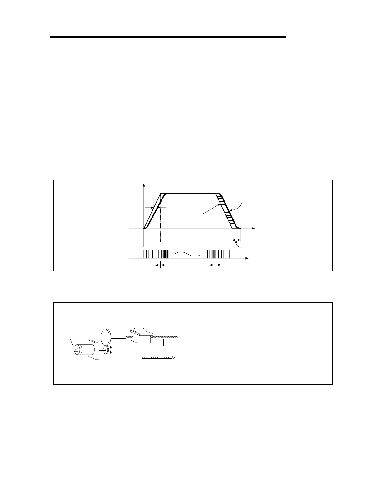
(b) Pulse train output from the QD70
1) As shown in Fig. 1.3, the pulse frequency increases as the servo motor
accelerates. The pulses are sparse when the servo motor starts and
more frequent when the servo motor speed comes close to the target
speed.
2) The pulse frequency stabilizes when the motor speed equals the target
speed.
3) The QD70 decreases the pulse frequency (sparser pulses) to
decelerate the servo motor before it finally stops the output.
There will be a little difference in timing between the decrease in the
pulse frequency and the actual deceleration and stopping of the servo
motor.
This difference, called "the stop settling time", is required for gaining a
stopping accuracy.
Speed V Pulse droop
amount
Pulse
distribution
Servomotor
speed
Acceleration
Deceleration
Time t
Stop
setting time
Pulse train Rough Dense
Rough
Fig. 1.3 QD70 output pulses
(2) Movement amount and speed in a system usi ng w orm g ear s
V
L
P0
P
Workpiece
Worm pear
Table
Pulse
generator
(PG)
Servomotor
A : Movement amount per pulse (mm/pulse)
Vs : Command pulse frequency (pulse/s)
n : No. of pulse generator slits
"
No. of pulses" (pulse/rev)
L : Worm gear lead (mm/rev)
R : Deceleration ratio
V : Movable section speed (mm/s)
N : Motor speed (r/min)
K : Position loop gain (1/s)
ε
: Deviation counter droop pulse amount
P0 : OP (pulse)
P : Address (pulse)
Fig. 1.4 System using worm gears

1 - 6 1 - 6
MELSEC-Q
1 PRODUCT OUTLINE
In the system shown in Fig. 1.4, the movement amount per pulse,
command pulse frequency, and the deviation counter droop pulser amount
are determined as follows:
1) Movement amount per pulse
The movement amount per pulse is determined by the worm gear lead,
deceleration ratio, and the No. of pulse generator slites.
The movement amount, therefore, is given as follows: (Number of
pulses output) × (Movement amount per pulse).
L
A =
R
×
n
[mm/pulse]
2) Command pulse frequency
The command pulse frequency is determined by the speed of the
moving part and movement amount per pulse.
V
Vs =
A
[pulse/s]
3) Deviation counter droop pulser amount.
The deviation counter droop pulser amount is determined by the
command pulse frequency and position loop gain.
Vs
ε
=
K
[pulse]
1 - 7 1 - 7
MELSEC-Q
1 PRODUCT OUTLINE
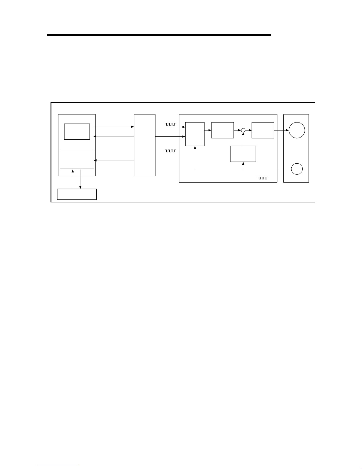
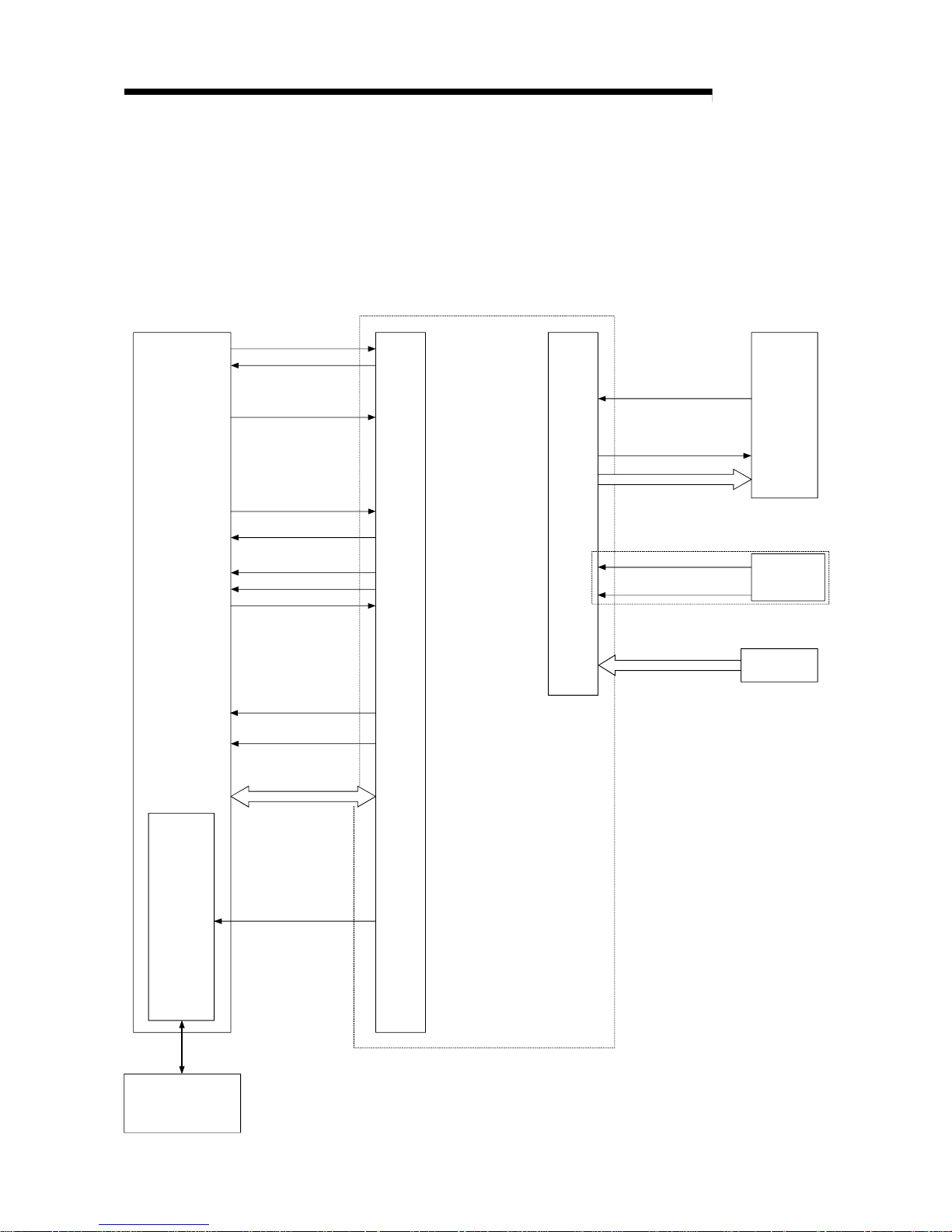
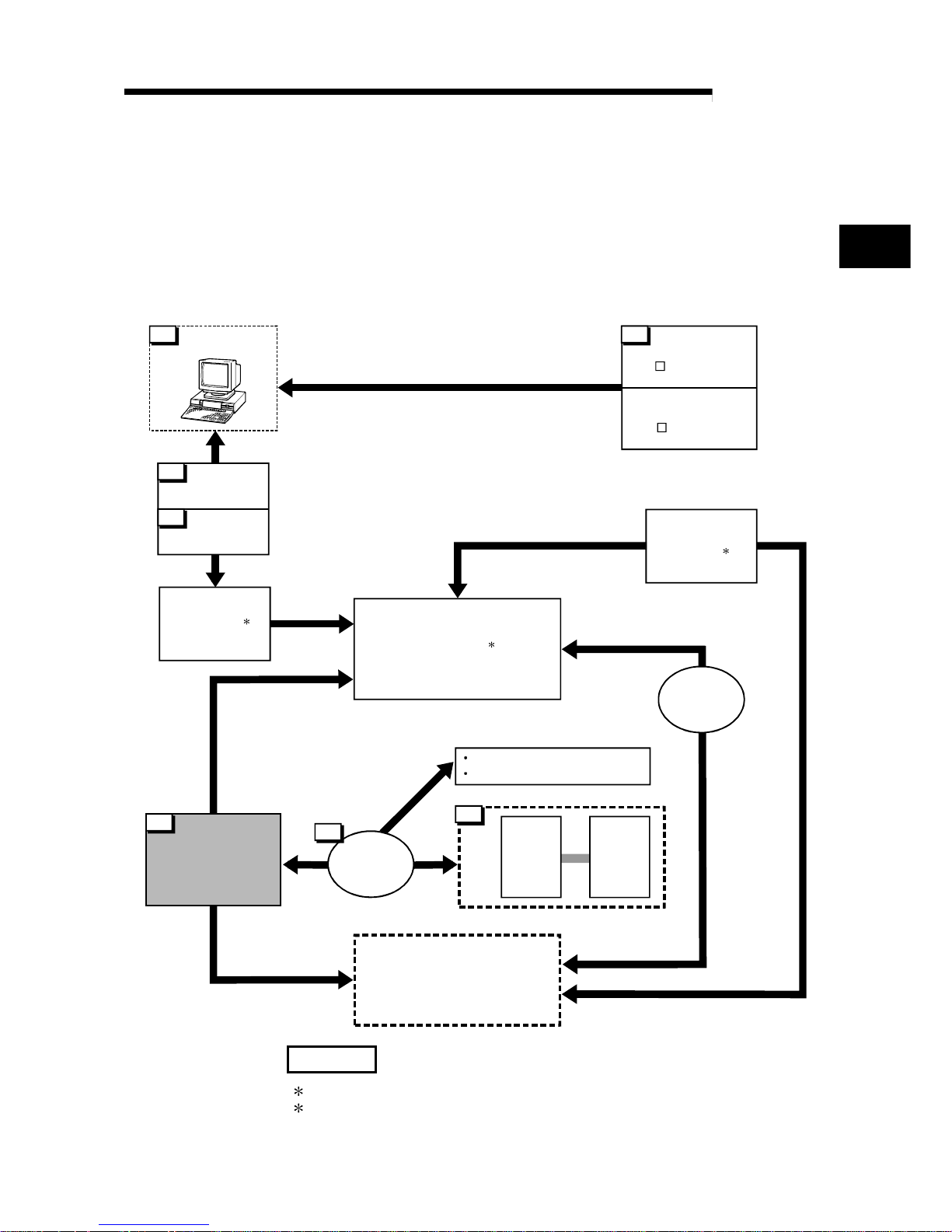
1.1.4 Communicating signals between QD 70 and each mo dul e
The outline of the signal communication between the QD70 (positioning module) and
PLC CPU, peripheral device (GX Configurator-PT) and drive unit, etc., is shown below.
(A peripheral device communicates with the QD70 via the PLC CPU to which it is
connected)
Refer to Chap te r 3 fo r de tails of the I/O si gn al s.
PLC READY signal
Module READY signal
JOG start signal
BUSY signal
Drive
unit
Deviation counter clear
Pulse train
QD70
Y0
X0
PLC CPU
Near-point dog singal
Monitor data
Y18 to Y1F
X10 to X17
Y10 to Y17
X1
Y8 to YF
X18 to X1F
X8 to XF
X2
Axis warning occurrence
signal
24VDC
Power supply
Peripheral device
(GX Configurator-PT)
Initial setting/ Auto refresh/
Operation monitor
Positioning start
Start comple te signal
Axis stop signal
Positioning complete
signal
Axis error occurrence
signal
Mechanical
system inputs
(Switches)
Speed-position switching
signal
(For pulse train output)
Zero signal
Date write/read
Interface
with
PLC CPU
Peripheral
device
interface
External
interface
1 - 8 1 - 8
MELSEC-Q
1 PRODUCT OUTLINE
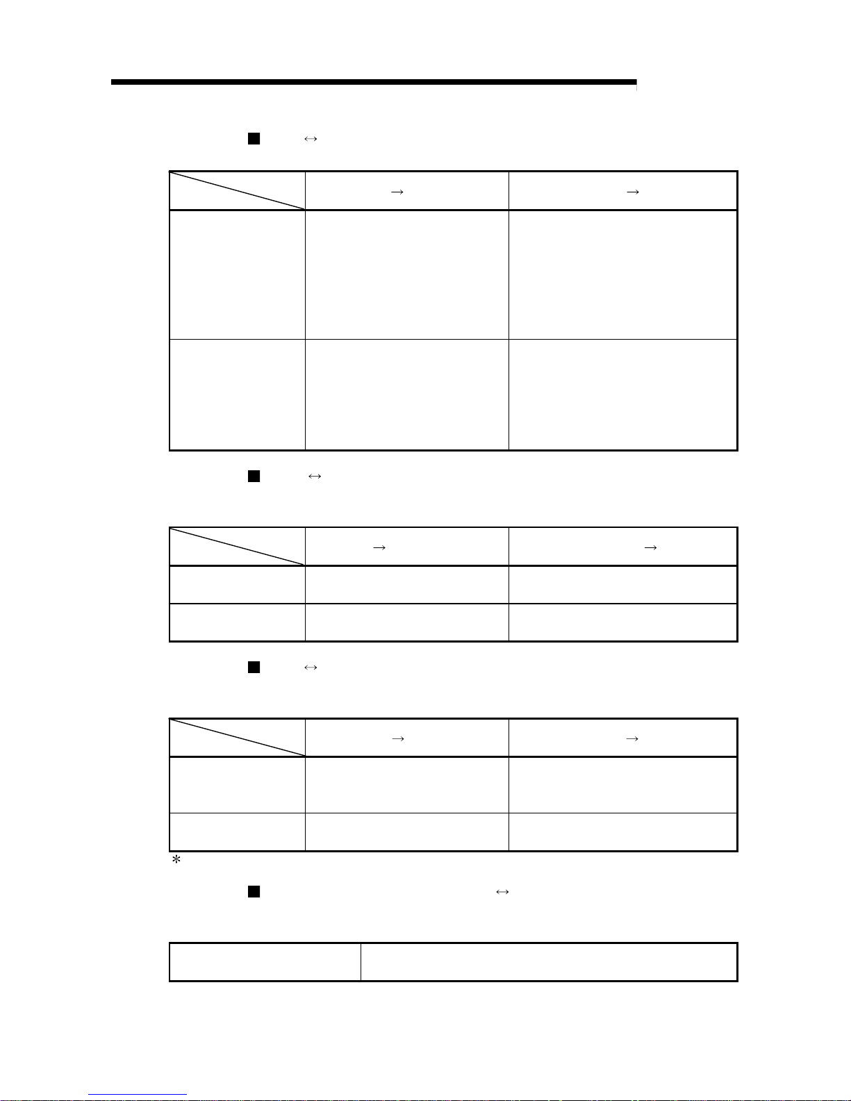
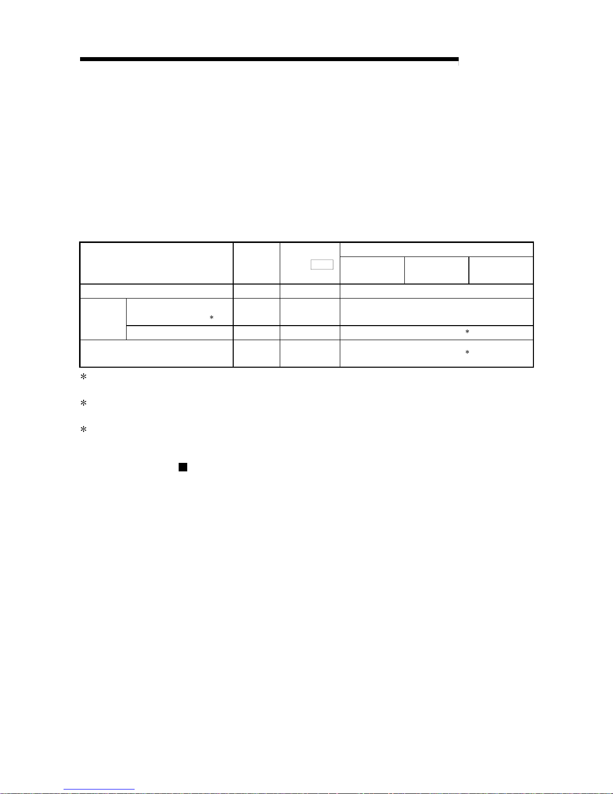
QD70 PLC CPU
The QD70 and PLC CPU communicate the following data via the base unit.
Direction
Communication
QD70
PLC CPU PLC CPU QD70
Control signal
Signal indication QD70 state.
•
Module READY (X0)
•
Axis error occurrence (X1)
•
Axis warning occurrence (X2)
•
BUSY (X8 to XF)
•
Start complete (X10 to X17)
•
Positioning complete (X18 to X1F)
Signal related to commands.
•
PLC READY (Y0)
•
Positioning start (Y8 to YF)
•
Axis stop (Y10 to Y17)
•
JOG start (Y18 to Y1F)
Data (read/write)
•
Parameter
•
OPR data
•
JOG data
•
Positioning data
•
Control data
•
Monitor data
•
Parameter
•
OPR data
•
JOG data
•
Positioning data
•
Control data
QCPU Peripheral device (GX Configurator-PT)
The QCPU and peripheral device make the following communications. (Refer to
Chapter 6 for de ta il s. )
Direction
Communication
QCPU
Peripheral device Peripheral device QCPU
Data –
•
Initial setting
•
Auto refresh setting
Operation monitor
•
Monitor data (QD70 buffer
memory/XY devices)
–
QD70 Drive unit
The QD70 and drive unit communicate the following data via the external device
connection connector.
Direction
Communication
QD70
Drive unit Drive unit QD70
Control signal
Signals related to commands
•
Deviation counter clear signal
(CLEAR)
Signal indicating OP
•
Zero signal (PG0)
Pulse train
•
Pulse train output (PULSE F/
PULSE R)
–
: External 24VDC must be supplied to output the pulse train.
Mechanical system inputs (switches) QD70
The input signals from the mechanical system inputs (switches) are entered into the
QD70 via the exte r nal dev i c e con ne cti on conn e cto r .
Mechanical system inputs (switches)
•
Near-point dog signal (DOG)
•
Speed-position switching signal (CHG)
1 - 9 1 - 9
MELSEC-Q
1 PRODUCT OUTLINE
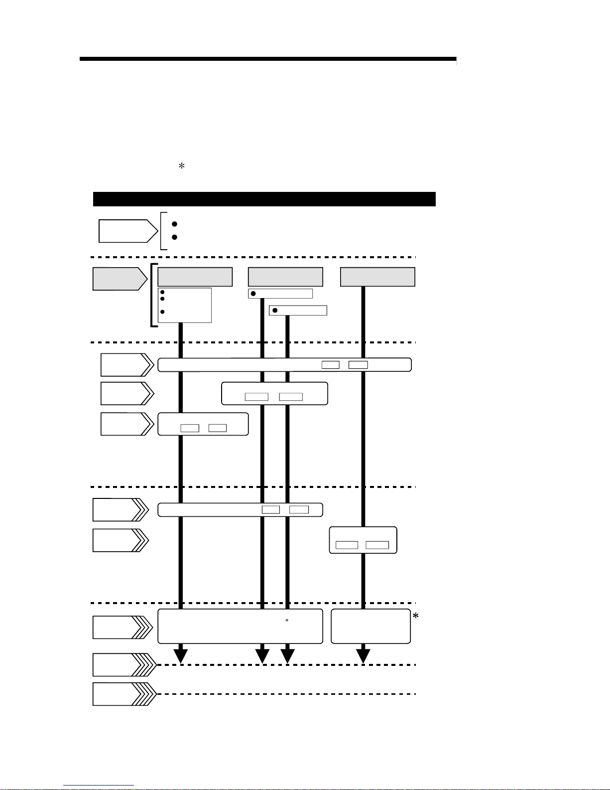
1.2 Positioning control
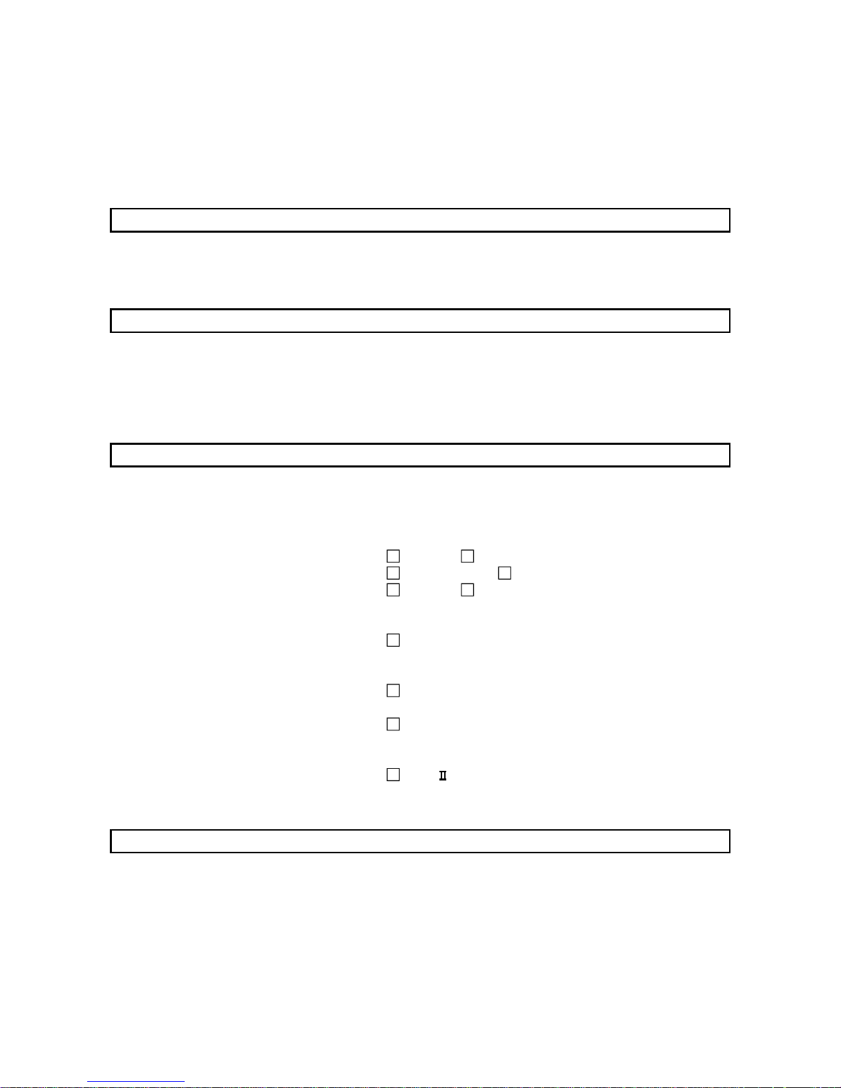
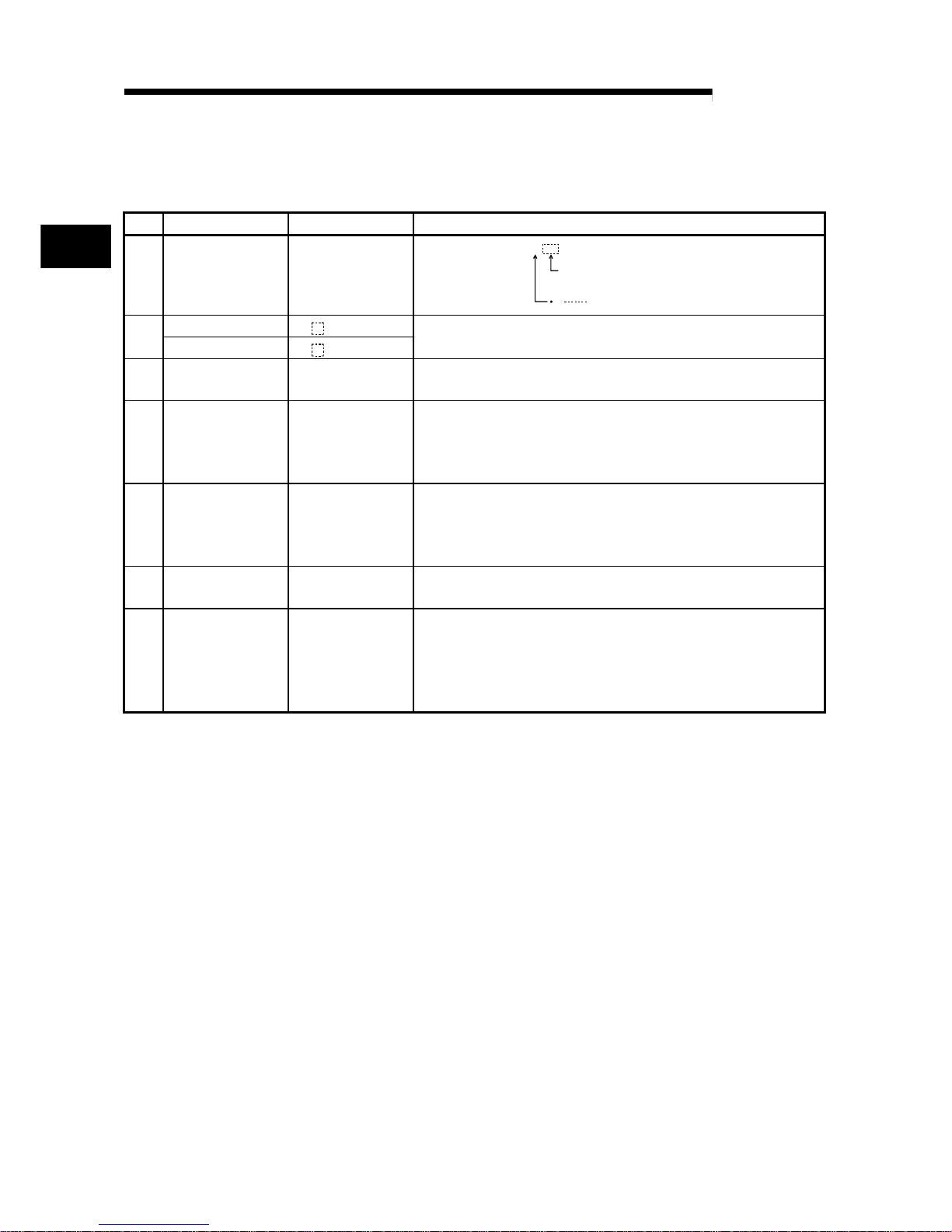
1.2.1 Outline of starting
The outline for starting each control is shown with the following flowchart.
It is assumed that each module is installed, and the required system configuration,
etc., has been prepared.
Machine OPR control
Fast OPR control
OPR control
Set the OPR data.
OPR. 1 to
OPR. 9
Preparation
Control
functions
Flow of starting
Installation and connection of module
Setting of hardware
Position control
Speed-position
switching control
Current value
changing
Positioning control
JOG operation
Parameter
Positioning
data
OPR data
Control data
Start signal
Control start
Control end
Set the parameters.
Set the start method.( Da. 1 to Da. 7 )
Operation
Stop
Turn ON the QD70 start signal
from the PLC CPU
Set the positioning data.
( Da. 1 to Da. 7 )
Set the JOG data
( JOG. 1 to JOG. 4 )
JOG data
( Pr. 1 to Pr. 10 )
: Positioning control can make a
multiple axes simultaneous start.
(Refer to "Section 9.3" for details.)
Turn the QD70 JOG
start signal ON from
the PLC CPU
1 - 10 1 - 10
MELSEC-Q
1 PRODUCT OUTLINE
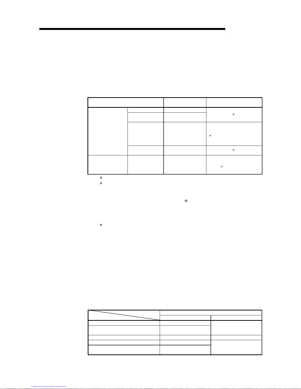
1.2.2 Outline of stopping
The possible causes of a control stop are as follows.
(1) Control ended normally
(2) An error occurred in the PLC CPU
(3) An error occurred in the QD70
(4) The axis stop signal from the PLC CPU turned ON
Stop processings performed in the above cases are outlined in the following table.
(Except the case (1) where control sto pped normally)
Stop processing
Stop factor
Stopped
axis
Axis operation
status (
Md. 4
)
after stop
OPR control
Positioning
control
JOG operation
PLC CPU error All axes Error Deceleration stop
Software stroke limit
upper/lower limit error
1
Axis by axis Error Deceleration stop
QD70 error
Other error Axis by axis Error
Deceleration stop
2
"Axis stop signal" from PLC CPU turned
ON
Axis by axis Stopped
Deceleration stop
3
1: By making parameter setting, you can set the software stroke limit valid/invalid. When the stroke limit is set invalid, a
deceleration stop is not made. (Refer to Section 4.2.)
2: If an illegal positioning data setting value caused an error during posit ion control (operation pattern: continuous path
control), an immediate stop is made at the positioning data prec eding th at illega l setting v alue. (R efer to Secti on 9.1.2.)
3: For position control (operation pattern: continuous path control), you can make parameter setting to select the
stopping method (position match stop or deceleration stop). (Refer to Section 4.2.)
Stop after multiple axes simultaneous start under positioning control
The axes started will not stop simultaneously. The stop command (axis stop signal
ON) must be given to each axis.
2 - 1 2 - 1
MELSEC-Q
2 SYSTEM CONFIGURATION
CHAPTER 2 SYSTEM CONFIGURATION
This chapter explains the system configuration of the QD70.
2.1 General image of system
The following is the general configuration including the QD70, PLC CPU, peripheral
device and others.
(The numbers in the sketch correspond to the "Nos." in the table in "Section 2.2
Component list" on the next page.)
Extension system
6
Drive
unit
Motor
4
5
RS-232
cable
USB cable
1
Positioning module
QD70P4/QD70P8
7
Connection
cable
Mechanical system inputs (switches)
Near-point dog signal
Speed-position switching signal
Extension
cable
Power supply
module
Main base unit
CPU module
3 2
GX Developer
(SW D5C-GPPW-E)
GX Configurator-PT
(SW D5C-QPTU-E)
Peripheral device
Personal
computer
1
2
2
REMARK
1: For the usable CPU module, refer to "Section 2.3 Applicable system".
2: For the usable base unit and power supply module, refer to the CPU Module
User's Manual.
2
2 - 2 2 - 2
MELSEC-Q
2 SYSTEM CONFIGURATION
2.2 Component list
A positioning system using the QD70 consists of the following components.
No. Product Type Remarks
1 Positioning module
QD70P4
QD70P8
QD70P
No. of control axes
Open collector output typeP
GX Developer SW D5C-GPPW-E
2
GX Configurator-PT SW
D5C-QPTU-E
For details, refer to the GX Developer Operating Manual and
"CHAPTER 6 UTILITY PACKAGE (GX Configurator-PT)".
3 Personal computer
DOS/V personal
computer
(User-prepared)
Refer to the GX Developer Operating Manual for details.
4 RS-232 cable QC30R2
(User-prepared)
RS-232 cable for connection of the CPU module and DOS/V personal
computer.
Refer to the GX Developer Operating Manual for details.
5 USB cable –
(User-prepared)
USB cable for connection of the CPU module and DOS/V personal
computer.
Refer to the GX Developer Operating Manual for details.
6 Drive unit –
(User-prepared)
Refer to the drive unit manual for details.
7
Connection cable
(for connection of
QD70 and drive unit)
–
(User-prepared)
Cable for connection of the QD70 and drive unit or mechanical system
input signals.
(To be fabricated in reference to the connected device manual and
Section 3.4.2)
2
2 - 3 2 - 3
MELSEC-Q
2 SYSTEM CONFIGURATION
2.3 Applicable system
The QD70 is usable with the following system.
(1) Applicable module and the number o f modules that ca n be i nstal led
The following are the CPU module and network module (for remote I/O stations)
in which the QD70 can be installed and the number of modules that can be
installed.
Applicable module
Number of modules that
can be installed
Remarks
Q00JCPU Maximum 16
Q00CPU
Q01CPU
Maxi mum 24
(
1
)
Q02CPU
Q02HCPU
Q06HCPU
Q12HCPU
Q25HCPU
Maxi mum 64
Can be installed in Q mode only
(
1
)
CPU module
Q12PHCPU
Q25PHCPU
Maxi mum 64
(
1
)
Network module
QJ72LP25-25
QJ72BR15
QJ72LP25G
QJ71LP25GE
Maxi mum 64
MELSECNET/H Remote I/O
station (
2
)
1 See User's Manual (Function Explanation, Program Fundamentals) for the CPU module to use.
2 See Q Corresponding MELSECNET/H Network System Reference Manual (Remote I/O
network).
(2) Base unit in which the QD70 can be installed
The QD70 can be installed in any I/O slot ( 3) of the base unit. However, a
power shortage may occur depending on the combination with other installed
modules and the number of modules used, so always take into consideration the
power supply capa city when installing mod ule s.
3 Limited to the range of the number of I/O points in the CPU module and network module (for
remote I/O stations) .
(3) Compatibility with a multiple PLC system
First read the QCPU (Q mode) User's Manual (Function Explanation, Program
Fundamentals) if the QD70 is used with a multiple PLC system.
Intelligent function module parameters
Perform PLC write of the intelligent function module parameters to the
control PLC of the QD70 only.
(4) Software packages supported
Correspondence between systems which use a QD70 and software packages
are as shown below.
The GX Developer is necessary when using a QD70.
Software version
GX Developer GX Configurator-PT
If installed in the Q00J/Q00/Q01CPU Version 7 or later
If installed in the Q02/Q02H/Q06H/Q12H/
Q25HCPU
Version 4 or later
Version 1.10L or later
If installed in the Q12PH/Q25PHCPU Version 7.10L or later Version 1.13P or later
If installed in a multiple PLC sy stem Version 6 or later
If installed in a MELSEC N ET/H r e mote I/O
station
Version 6 or later
Version 1.10L or later
2 - 4 2 - 4
MELSEC-Q
2 SYSTEM CONFIGURATION
2.4 How to check the function version and the softwar e v ersion
The function version of the QD70 and the software version of the GX Configurator-PT
can be checked in the following methods.
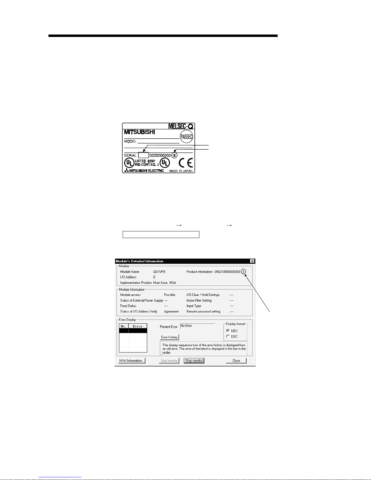
[1] How to check the function version of the QD70
(a) Method using the rated plate on the module side face
Check the alphabet at the end of "SERIAL".
09021
SERIAL No. (The first five digits)
Function version
(b) Method using the peripheral device
Check the alphabet at the end of "Product information" displayed on
System monitor "Module's Detailed Information" of GX Developer.
[Operation of GX Developer]
Choose [Diagnostics] [System monitor] "QD70 module" and choose
Module's Detailed Information
.
<GX Developer display screen>
Function version
2 - 5 2 - 5
MELSEC-Q
2 SYSTEM CONFIGURATION
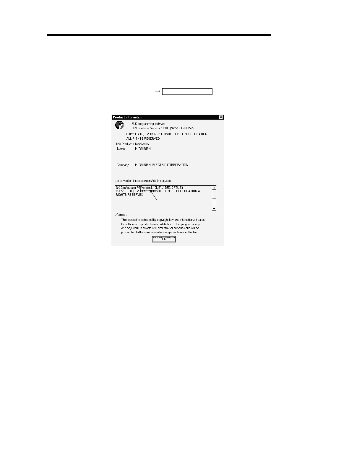
[2] How to check the software version of the GX Configur ator -PT
Check the "Product information" displayed on "Help" of GX Developer.
[Operation of GX Developer]
Choose [Help] Product information
<GX Developer display screen>
Software version
3 - 1 3 - 1
MELSEC-Q
3 SPECIFICATIONS AND FUNCTIONS
CHAPTER 3 SPECIFICATIONS AND FUNCTIONS
This chapter describes the performance specifications of the QD70 and the
specifications of the I/O signals transferred to/from the PLC CPU and external device.
For the general specifications of the QD70, refer to the user's manual (hardware) of the
CPU module used.
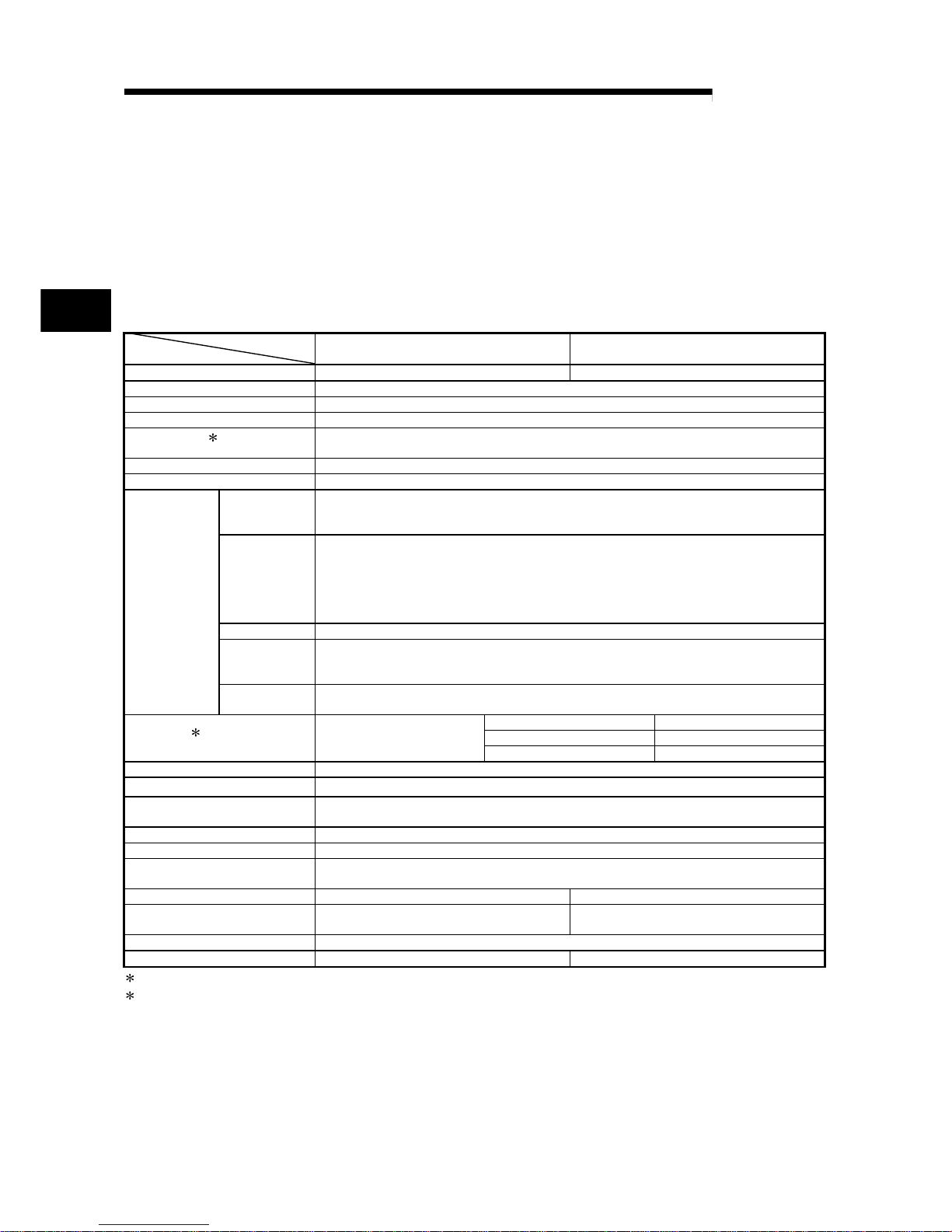
3.1 Performance specifications
Model
Item
QD70P4 QD70P8
No. of control axes 4 axes 8 axes
Interpolation function No
Control method PTP (Point To Point) control, path control (linear only), speed-position switching control
Control unit pulse
Positioning data
1
10 pieces of data (positioning data No. 1 to 10)/axis
(can be set using GX Configurator-PT or sequence program)
Peripheral device/utility package GX Configurator-PT (option)
Data backup No
Positioning
control method
PTP control : Incremental system/absolute system
Speed-position switching control : Incremental system
Path control : Incremental system/absolute system
Positioning
control range
[Absolute system]
-2147483648 to 2147483647pulse
[Incremental system]
-2147483648 to 2147483647pulse
[Speed-position switching control]
0 to 2147483647pulse
Speed command 0 to 200000pulse/s
Acceleration/
deceleration
processing
Trapezoidal acceleration/deceleration
Positioning
control
Acceleration/
deceleration time
0 to 32767ms
1-axis start 0.1ms
4-axes simultaneous start 0.2ms
Starting time
2
Position control
8-axes simultaneous start 0.4ms
External wiring connection system 40-pin connector
Applicable wire size 0.3mm2 (for use of A6CON1), AWG#24 (for use of A6CON2)
External device connection
connector
A6CON1, A6CON2 (option)
Pulse output method Open collector output
Max. output pulse 200kpps
Max. connection distance between
QD70 and drive unit
2m
Internal current consumption (5VDC) 0.55A 0.74A
External 24V current consumption
(24VDC)
0.065A 0.12A
No. of occupied I/O points 32 points (I/O assignment: Intelligent function module 32 points)
Weight 0.15kg 0.17kg
1
: Positioning data can be started from No.1 only. (Cannot be started from any of No.2 to No.10.)
2
: A delay may occur depending on the operating conditions and starting conditions (control method, bias speed, ACC/DEC time, etc.) of
the other axes.
3
3 - 2 3 - 2
MELSEC-Q
3 SPECIFICATIONS AND FUNCTIONS
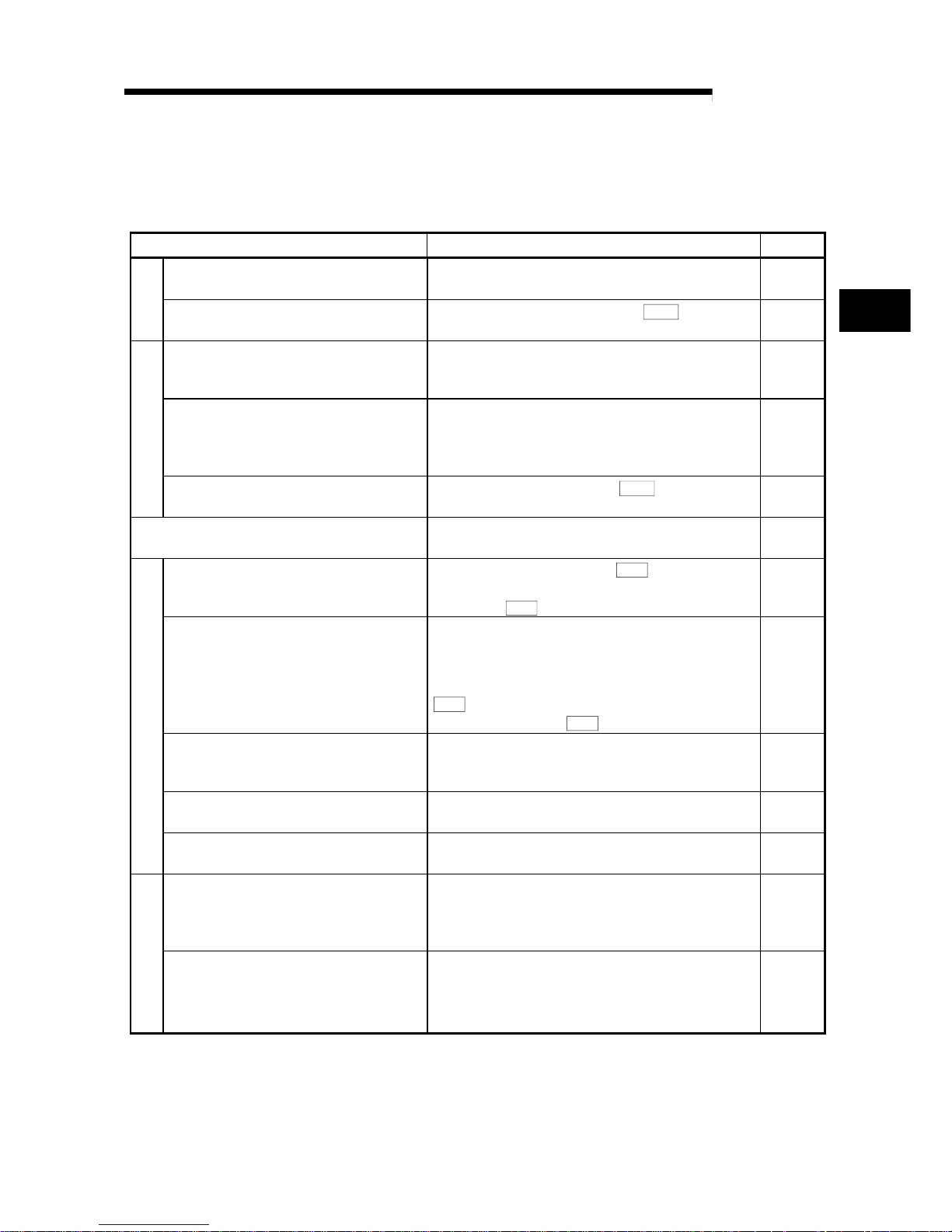
3.2 List of functions
The following table lists the functions of the QD70.
(Read "SECTION 2 CONTROL DETAILS AND SETTING" for details of the functions.)
Function name Description Reference
Machine OPR control
Mechanically establishes the positioning control start
point using a near-point dog or stopper.
Section
8.2
OPR control
Fast OPR control
Positions a target to the OP address (
Md. 1
Current feed
value) stored in the QD70 using machine OPR control.
Section
8.3
Position control (1-axis linear control)
Positions a target using a linear path to the address set in
the positioning data or to the position designated with the
movement amount.
Section
9.2.2
Speed-position switching control
First, carries out speed control, and then carries out
position control (positioning control with designated
address or movement amount) by turning the "speedposition switching signal" ON.
Section
9.2.3
Positioning control
Current value changing
Changes the Current feed value (
Md. 1
) to the address
set in the positioning data.
Section
9.2.4
JOG operation
Outputs a pulse to drive unit while the JOG start signal is
ON.
Chapter
10
Speed limit function
If the command speed exceeds "
Pr. 5
Speed limit value"
during control, this function limits the commanded speed
to within the "
Pr. 5
Speed limit value" setting range.
Section
11.2
Speed change function
This function changes the speed at any point during
speed control of speed-position switching control or
during JOG operation.
Set the new speed in the speed change buffer memory
(
Pr. 7
New speed value), and change the speed with the
Speed change request (
Pr. 6
).
Section
11.3
Software stroke limit function
If a command outside of the upper/lower limit stroke limit
setting range, set in the parameters, is issued, this
function will not execute positioning for that command.
Section
11.4
Acceleration/deceleration processing function
This function adjusts the acceleration/deceleration
processing of control.
Section
11.5
Sub function
Restart function
This function resumes positioning control during a stop of
the axis from where it had stopped.
Section
11.6
External I/O signal logic switching function
This function changes the external I/O signal logic to
match the externally connected device.
It can be changed by making the intelligent function
module switch setting.
Section
12.2
Common function
External I/O signal monitor function
This function monitors the external I/O signal states using
GX Developer.
Section
5.5
Section
12.3
3
 Loading...