

September. 2016
Model : TECHNICAL MANUAL
DIRECT EXPANSION COIL UNIT FOR LOSSNAY
GUG-01SL-E
GUG-02SL-E
GUG-03SL-E
Lossnay Return Air and Supply Air
Temperature Control
Now Possible!

i
CONTENTS
CHAPTER 1 What Dx-coil unit is
1. Basic function
...................................................................................................................................................
1
2. Two temperature control method
.....................................................................................................................
1
CHAPTER 2 System configurations
1. System pattern outline
....................................................................................................................................
3
2. Technical notes
.................................................................................................................................................
5
3. The conditions when Dx-coil unit is forcibly thermo-OFF
..................................................................................
9
4. Water level sensor
............................................................................................................................................
9
5. Drain pump operation
.......................................................................................................................................
9
CHAPTER 3 Specifications
1. Operation range
................................................................................................................................................
10
2. Connectable Lossnay unit and outdoor unit for each functions
........................................................................
10
3. Refrigerant pipe size information
......................................................................................................................
10
4. Specifications
....................................................................................................................................................
11
5. Characteristic curve
..........................................................................................................................................
13
CHAPTER 4 Outlines and Dimensions
1. Outlines and dimensions
...................................................................................................................................
16
2. Installation example
..........................................................................................................................................
18
CHAPTER 5 Wiring Diagram
1. Wiring diagram
..................................................................................................................................................
20
2. Connecting the power supply cable
..................................................................................................................
21
3. Connecting PZ-01RC
........................................................................................................................................
21
4. Connecting Lossnay unit
...................................................................................................................................
21
CHAPTER 6 Other Functions
1. Function setting
.................................................................................................................................................
22
2. Dip switch setting
..............................................................................................................................................
27
3. Lossnay functions
.............................................................................................................................................
27
CHAPTER 7 Remote Controller PZ-01RC
1. Remote controller PZ-01RC
..............................................................................................................................
28
2. Menu list
............................................................................................................................................................
28
3. Appearance
.......................................................................................................................................................
29
4. Outlines and dimensions
...................................................................................................................................
30
5. Initial setting
......................................................................................................................................................
31
6. Basic operations
...............................................................................................................................................
33
7. Troubleshooting
................................................................................................................................................
33
8. Timer and Weekly timer
....................................................................................................................................
34
9. Service
..............................................................................................................................................................
34
10. Others
...............................................................................................................................................................
34
CHAPTER 8 Refrigerant system diagram
1. Refrigerant system diagram
..............................................................................................................................
35
CHAPTER 9 Model selection and capacity calculation
...................................................................
36
CHAPTER 10 Performance Data
1. Air volume factor
..............................................................................................................................................
62
2. Performance curves
..........................................................................................................................................
62
3 . Capacity ratio against corrected refrigerant pipe length
...................................................................................
63
4. Quick reference for the air condition difference factor C2
.................................................................................
63
5. Cooling capacity and SHF (sensible heat factor) table against return and outdoor air temperature.
...............
65

ii
1
CHAPTER1
What Dx-coil unit is
PZ-01RC
SA
RA
OA
EA
Outdoor unit
Lossnay unit
Power supply
Power supply
Dx-coil unit
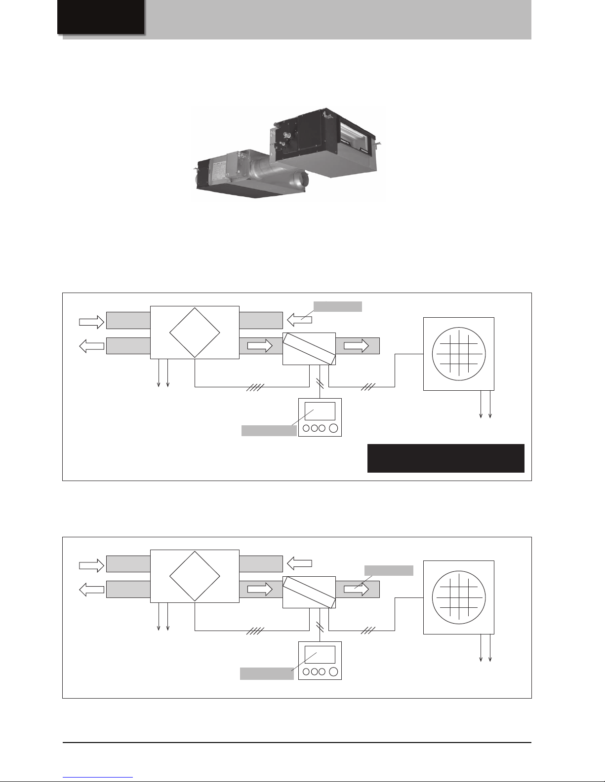
Dx-coil (Direct Expansion Coil) unit is a kind of temperature control equipment working with Lossnay unit and Mr.Slim outdoor
unit to control Return Air temperature or Supply Air temperature.
2.2 SA (Supply Air) temperature control
1. Basic function
2.Two temperature control method
2.1 RA (Return Air) temperature control
As same as air-conditioner, users set the target return air temperature on the remote controller and then Dx-coil unit will operate
to heat up or cool down the room temperature.
This picture shows the system of LGH-100RVX-E and GUG-02SL-E as example.
Users set the target supply air temperature on the remote controller and then Dx-coil unit will maintain the supply air
temperature close to the setting temperature.
Connection image
Lossnay unit
Dx-coil unit
PZ-01RC
SA
RA
OA
EA
Outdoor unit
Lossnay unit
Power supply
Power supply
Dx-coil unit
The dedicated remote controller for the Dx-coil unit is
described as “PZ-01RC” in this manual.
It is not an official model name.
OA: Outdoor air
EA: Exhaust air
SA: Supply air
RA: Return air
Setting temp.
Setting temp.
Target temp.
Target temp.
2
CHAPTER1 What Dx-coil unit is/ 2.Two temperature control method
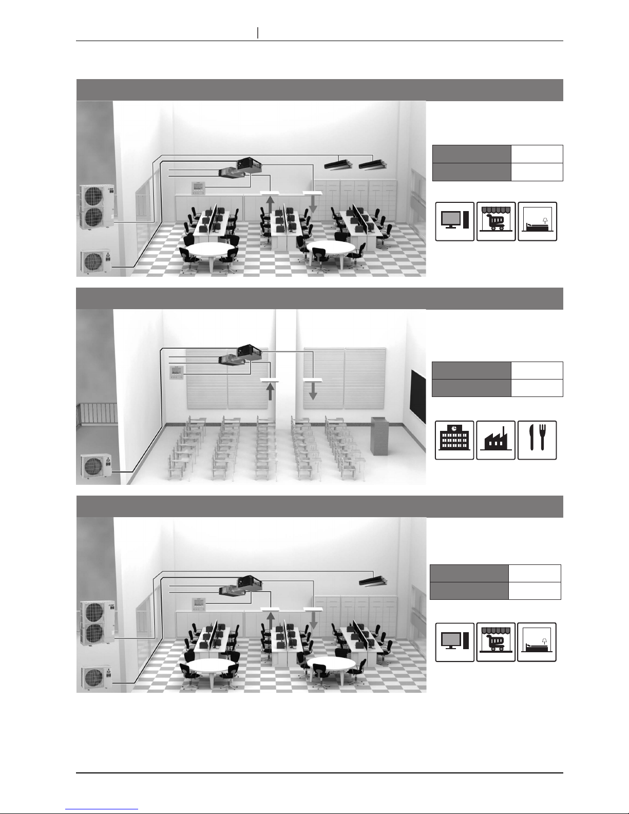
2.3 Application examples
Supplemental Air-conditioning System
Target Segment:
Supplemental air-conditioning systems
that combine the use of Dx-coil and
Lossnay units are now possible.
Offices
Small shops
Hotels
RA Temperature Control
Temperature setting range
Heating: 17-28°C / Cooling: 19-30°C / Auto: 19-28°C
Dx-coil unit
Dx-coil unit RC
Mr.Slim
Power lnverter
Series
Lossnay
Necessary fresh
air volume
Medium
Necessary Heating and
Cooling capacity
Medium
Main Air-conditioning System
Target Segment:
If the required heating and cooling
capacity is not so high, a Dx-coil and
Lossnay package solution is possible
for air-conditioning and ventilation
needs.
Schools Factories
Restaurants
RA Temperature Control
Temperature setting range
Heating: 17-28°C / Cooling: 19-30°C / Auto: 19-28°C
Necessary fresh
air volume
Large
Necessary Heating and
Cooling capacity
Small
Outdoor Air Treatment
Target Segment:
Controlling the temperature of outdoorair supplied via the Dx-coil and Lossnay
units simplifies air-conditioning design
and control.
Offices
Small shops
SA Temperature Control
Temperature setting range
Heating: 17-28°C / Cooling: 12-30°C
Hotels
Necessary fresh
air volume
Medium
Necessary Heating and
Cooling capacity
Medium
Dx-coil unit
Dx-coil unit RC
Lossnay
Mr.Slim
Power lnverter
Series
Mr.Slim
Power lnverter
Series
Dx-coil unit
Dx-coil unit RC
Lossnay
3
CHAPTER2
System configurations
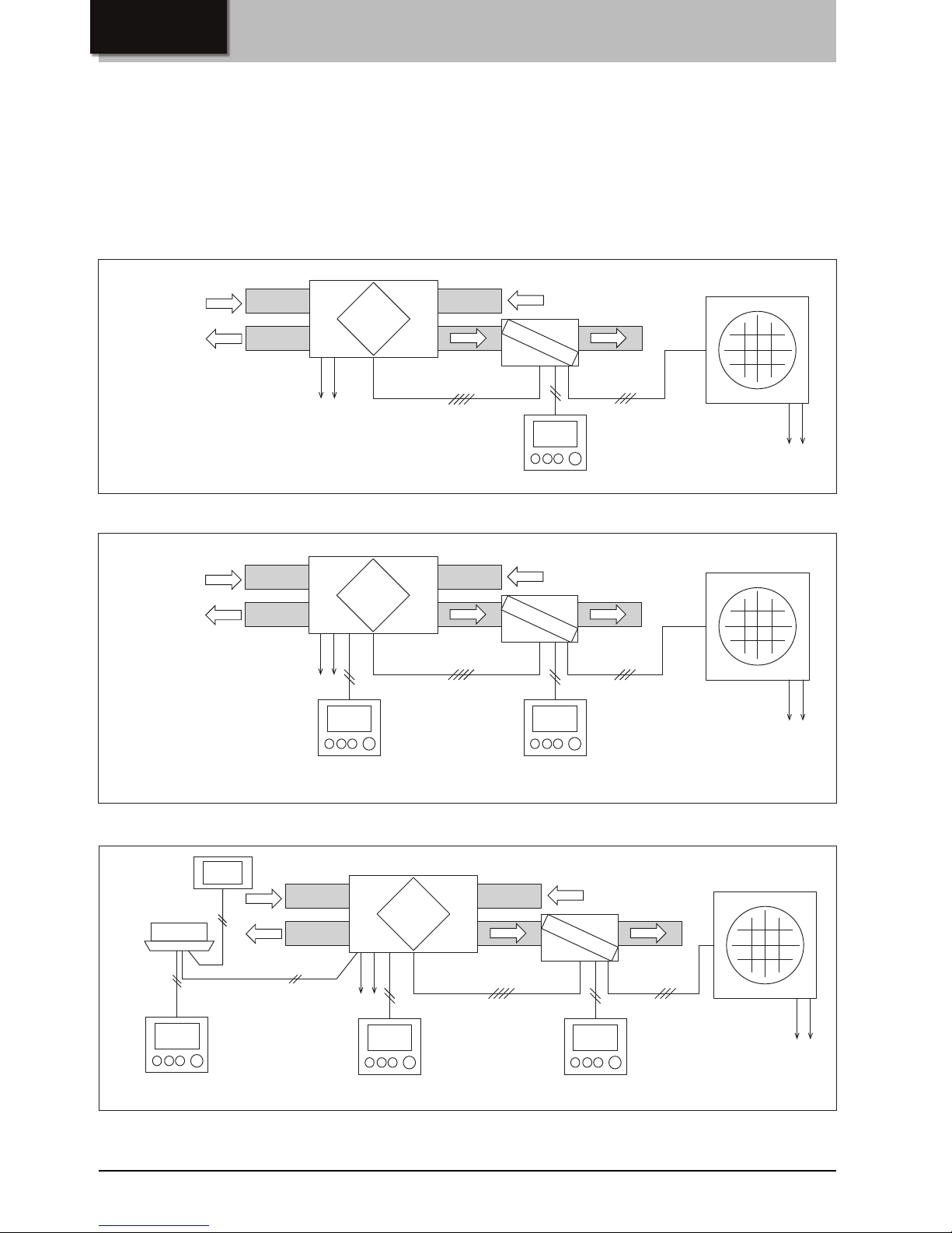
The system of Lossnay unit and Dx-coil unit can be used as a few system patterns.
• System pattern X: One remote controller
• System pattern Y: Two remote controllers
• System pattern Z: M-NET connection
Depending on the pattern, the way to operate system, available functions, information can be monitored etc. are different. See
the following gures and tables.
1. System pattern outline
1.1 System pattern X: One remote controller
1.2 System pattern Y: Two remote controllers
1.3
System pattern Z: M-NET connection
(Interlocked with City Multi indoor unit when necessary)
<CAUTION>
Dx-coil unit cannot be monitored nor operated from M-NET system controller.
PZ-01RC
SA
RA
OA
EA
Outdoor unit
Lossnay unit
Power supply
Power supply
Dx-coil unit
PZ-01RC
Lossnay remote controller
(PZ-61DR-E)
SA
RA
OA
EA
Outdoor unit
Lossnay unit
Power supply
Power supply
Dx-coil unit
Lossnay remote controller
(PZ-61DR-E if necessary)
MA remote controller
(If necessary)
M-NET system controller
(If necessary)
City Multi indoor unit
(Interlocked with Lossnay
when necessary)
PZ-01RC
SA
RA
OA
EA
Outdoor unit
Lossnay unit
Power supply
Power supply
Dx-coil unit
4
CHAPTER2 System configurations/ 1. System pattern outline
*1: When one of the two remote controllers is switched ON/OFF, the other remote controller switches ON/OFF synchronously.
*2: When one of the three remote controllers is switched ON/OFF, the other remote controllers switch ON/OFF synchronously.
Or when the indoor unit is switched ON/OFF, the system of the Lossnay unit and Dx-coil unit switches ON/OFF synchronously.
*3: Cannot be controlled by M-NET system controller nor MA remote controller of the indoor unit.
*4: Fan speeds can be changed by 0-10VDC input or a volt free contact and can be xed at the fan speed 3 if necessary.
*5: The ventilation mode is set to the heat recovery mode during the heating and fan modes.
The ventilation mode can be set to the bypass ventilation mode by a volt-free contact if necessary.
*6:
When Lossnay is interlocked with City Multi indoor unit, the target temperature information and the operation mode information from Dx-coil have a priority used for
automatic ventilation mapping or Night-purge starting condition etc..
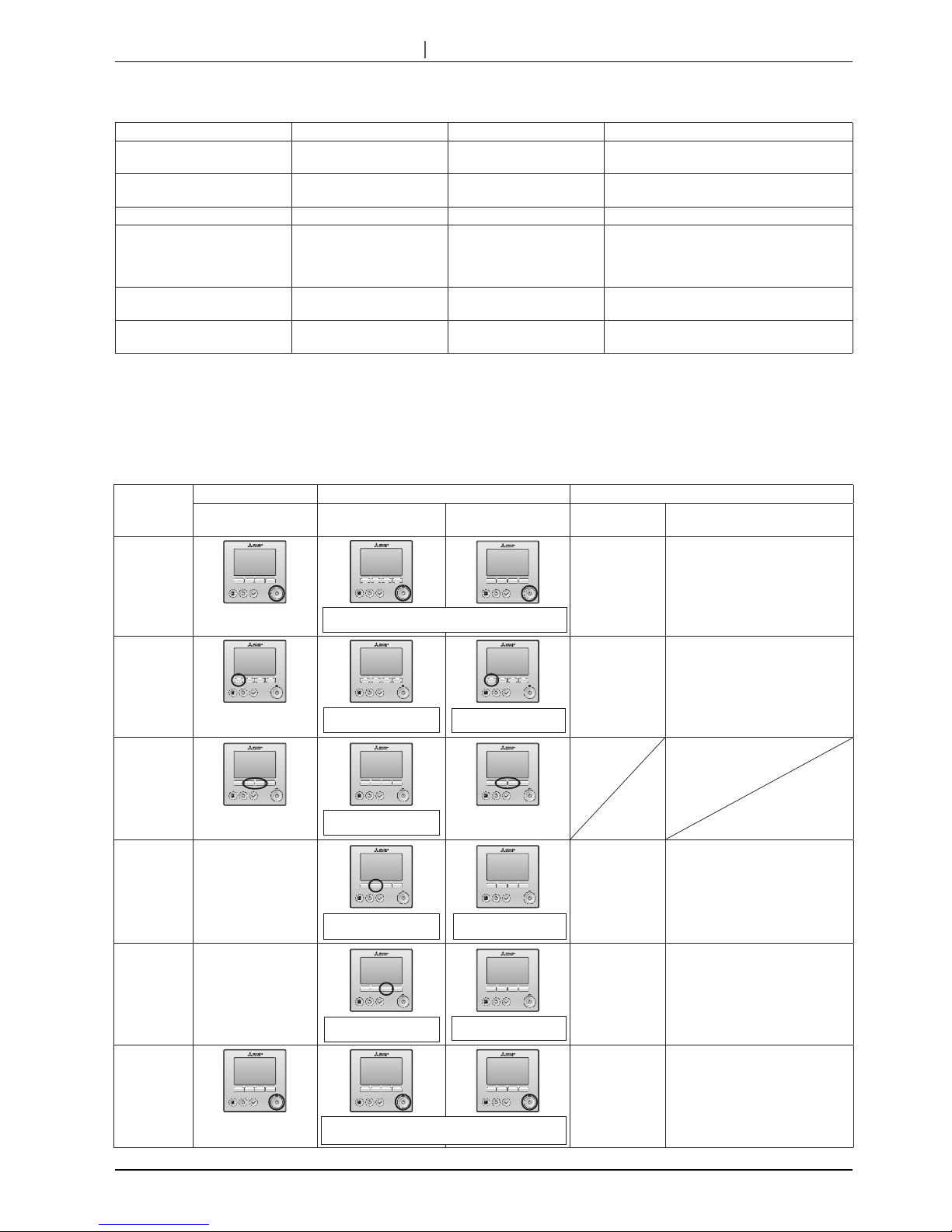
1.4 Operation from each remote controller
System pattern X System pattern Y System pattern Z
ON/OFF From PZ-01RC From PZ-01RC or
PZ-61DR-E *1
From one of the remote controllers or when
the indoor unit is switched ON/OFF *2
Operation mode
[Heating/Cooling/Fan]
From PZ-01RC From PZ-01RC Only from PZ-01RC *3
Temp. setting From PZ-01RC From PZ-01RC Only from PZ-01RC *3
Fan speed
[FS1 / FS2 / FS3 / FS4]
Fixed at FS4 *4 Can be changed from
PZ-61DR-E.
Can be changed from PZ-61DR-E, M-NET
system controller or MA remote controller (for
the indoor unit). The selectable fan speeds
depend on the model of remote controller.
Ventilation mode
[Heat recovery / Bypass / Auto]
Fixed at automatic mode *5 Can be changed from
PZ-61DR-E.
Can be changed from PZ-61DR-E or M-NET
system controller.
Remarks - - Dx-coil unit cannot be monitored nor operated
from M-NET system controller.*6
Basic
operation
System pattern X System pattern Y Unit status
Dx-coil unit remote
controller (PZ-01RC)
Lossnay unit remote
controller (PZ-61DR-E)
Dx-coil unit remote
controller (PZ-01RC)
Lossnay unit Dx-coil unit
ON ON ON
Heating
Cooling
Fan
Auto
Ventilating
Heating and Cooling:
Thermo-ON or thermo-OFF depending
on temperature conditions
Fan: Always thermo-OFF (ventilatio only)
Auto: Only available at RA temp. control
Temperature
setting
Fan speed
Fixed at fan speed 4
(Fan speed can
be changed by the
external input to
Lossnay and be xed
at fan speed 3 if
necessary.)
Operating at
selected fan
speed
When Lossnay unit goes to fan
speed 1 or 2 during thermo-ON,
Dx-coil unit becomes thermo-OFF
forcibly.
Ventilation
mode
Fixed at automatic mode
(The ventilation mode is
always the heat recovery
mode during the heating
and fan mode.)
Operating
at selected
ventilation mode
The Dx-coil unit can be switched
thermo-ON in any ventilation
mode depending on temperature
conditions.
OFF OFF OFF
When one of the two remote controllers is switched ON,
the other remote controller switches ON synchronously.
Cannot be changed by
PZ-61DR-E.
Heating/Cooling/Fan/Auto
Cannot be changed by
PZ-61DR-E.
Fan speed 1, 2, 3 or 4
Cannot be changed by
PZ-01RC.
Heat recovery/Bypass/Auto
Cannot be changed by
PZ-01RC.
When one of the two remote controllers is switched OFF,
the other remote controller switches OFF synchronously.
For system pattern Z, the functions that can be used depend on the model of remote controllers.
5
CHAPTER2 System configurations/ 2.Technical notes
1.5 External fan speed control without Lossnay remote controller
When Lossnay remote controller (PZ-61DR-E) is not used in the system pattern X or Z, Lossnay fan speed can be controlled by
external input like 0-10VDC (CN26) or volt-free contact (CN17).
Refer to the installation manual and the technical manual of Lossnay unit for more detailed information such as how to set, how
to select.
The selection of Temp. priority mode or Fan speed priority mode can be set. Please refer to No.10 on page 25 and 26.
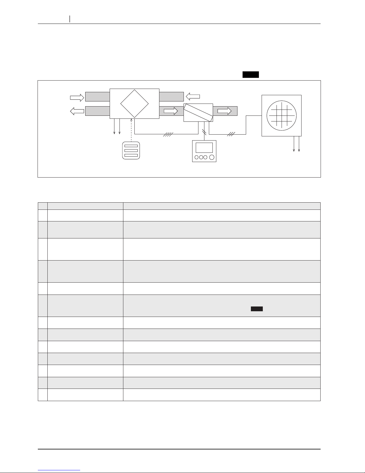
2. Technical notes
For the details of No.8, 9, 10, 11 and 12, see the following pages.
PZ-01RC
SA
RA
OA
EA
Outdoor unit
Lossnay unit
Power supply
Power supply
Dx-coil unit
0-10VDC input(CN26)
or
volt-free contact(CN17)
CO
2
sensor
(field supply)
No.
Item Contents
1
Fan speed 1 and 2 When Lossnay supply fan is the fan speed 1 or 2, Dx-coil unit always switches thermo-OFF.
2
Night purge When Lossnay is in Night purge mode, Dx-coil unit always switches thermo-OFF and PZ-01RC is
the same as the normal operation screen.
PZ-61DR-E or AE-200E is required for the Night-purge function.
3
Heating stops when the OA temp. is
19 ˚C or higher
[GUG-03SL-E, SA temperature control and heating mode only]
When the OA temperature is 19 ˚C or higher, Dx-coil unit switches thermo-OFF to protect the
compressor of the outdoor unit.(This “OA temperature” is the detected temperature by outdoor
unit. It is not the detected temperature by Lossnay unit.)
4
Intermittent operation - When the OA temperature is between -10 ˚C and -15 ˚C, Lossnay oparates 60 minutes ON and
10 minutes OFF. During the ‘10 minutes OFF’, Dx-coil unit switches thermo-OFF.
- When the OA temperature is lower than -15 ˚C, Lossnay operates 5 minutes ON and 55 minutes
OFF. During the ‘5 minutes ON’, Dx-coil unit switches thermo-OFF.
5
Defrost and heating standby mode During defrost and heating standby mode, Lossnay supply fan stops but exhaust fan continues to
run as factory setting.
6
Error indication During heating or cooling modes, PZ-01RC displays an error code on its screen.
During fan mode, PZ-01RC changes to heating mode and displays an error code. If automatic
change to heating mode is not required, please set the function
No.7
to pattern B. Refer to page
24 for details.
7
Drain pump The drain pump operates during cooling mode and operates for 6 minutes after Dx-coil unit stops.
The drain pump will make a noise while operating.
8
One-to-one connection For the system, the number of Lossnay unit, Dx-coil unit, PZ-01RC and outdoor unit must be one.
Multiple-units connection is prohibited.
9
PZ-43SMF-E
PZ-60DR-E
PZ-43SMF-E and PZ-60DR-E are prohibited to use in the system of Lossnay and the Dx-coil unit.
10
Interlocking with Mr. Slim indoor unit Interlocking Mr. Slim indoor unit with Lossnay unit by using CN2L connector is prohibited.
11
One system in one group If the system is on M-NET, only one system can be used within a group. Multiple systems in one
group is prohibited. One system and Lossnay unit(s) in one group is also prohibited.
12
M-NET adapter Do not use M-NET adapter for the outdoor unit.
13
Apportioned electricity charge
function of AE-200E
Not available
6
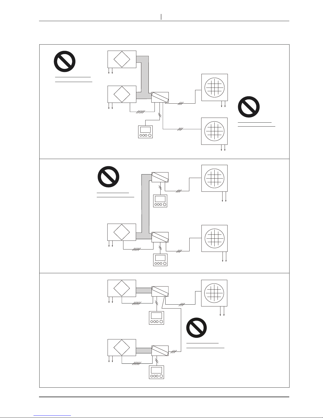
CHAPTER2 System configurations/ 2.Technical notes
Following congurations are bad examples. Do not construct systems same as below.
Lossnay unit
Dx-coil unit
Dx-coil unit
Multiple Dx-coil units
connection is prohibited.
Dx-coil unit
Multiple Dx-coil units
connection is prohibited.
Dx-coil unit
Lossnay unit
Outdoor unit
Power supply
Power supply
Power supply
Lossnay unit
Power supply
Multiple Lossnay units
connection
is prohibited.
Outdoor unit
PZ-01RC
Multiple outdoor units
connection is prohibited.
Dx-coil unit
Outdoor unit
Power supply
PZ-01RC
Outdoor unit
Power supply
PZ-01RC
Power supply
PZ-01RC
Lossnay unit
Power supply
PZ-01RC
Lossnay unit
Power supply
Outdoor unit
Power supply
Prohibition for multiple connection.
7
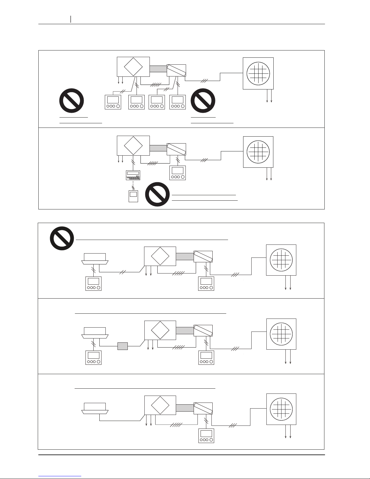
CHAPTER2 System configurations / 2.Technical notes
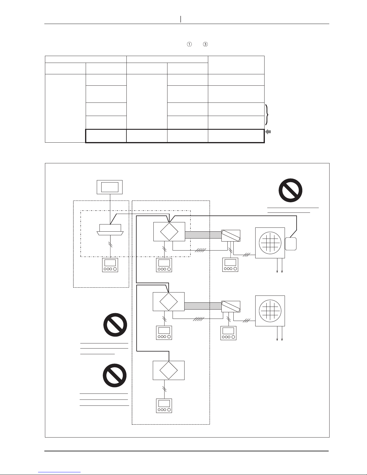
Following congurations are bad examples. Do not construct systems same as below.
Prohibition for TM2 connection of Lossnay.
Two PZ-01RC
connection is prohibited.
Two PZ-61DR-E
connection is prohibited.
Dx-coil unit
PZ-60DR-E
PZ-60DR-E connection is prohibited.
PZ-43SMF-E connection is prohibited.
PZ-43SMF-E
Dx-coil unit
PZ-01RC
Lossnay unit
Power supply
Outdoor unit
Power supply
PZ-01RC
PZ-01RC
Lossnay unit
Power supply
Power supply
Outdoor unit
PZ-61DR-EPZ-61DR-E
Mr. Slim
indoor unit
MA remote controller
Interlocking Mr. Slim indoor unit with Lossnay unit by using CN2L connector is prohibited.
CN2L
Dx-coil unit
External
device
Interlocking external device with Lossnay unit by using TM2 ①and ③is available.
OK
e.g. Non-Mitsubishi
Air-conditioner
Dx-coil unit
TM2 ①③
TM2 ①③
Mr. Slim
indoor unit
MA remote controller
CN2L
Dx-coil unit
PZ-01RC
Lossnay unit
Power supply
Outdoor unit
Power supply
PZ-01RC
PZ-01RC
Lossnay unit
Power supply
Power supply
Power supply
Power supply
(Optional)
Interlocking Mr. Slim indoor unit with Lossnay unit by using PAC-SF40RM-E is available.
OK
PAC-SF40RM-E
Lossnay unit
Outdoor unit
Outdoor unit
Prohibition for Lossnay remote controller.
8
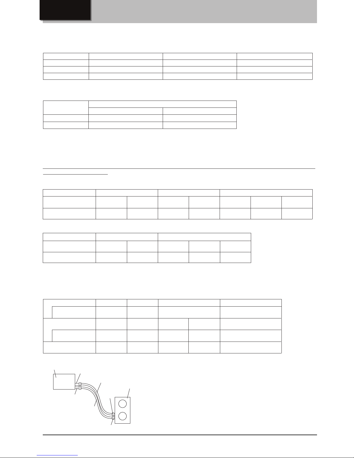
CHAPTER2 System configurations / 2.Technical notes
<CAUTION>
When interlocking with Mr.Slim or external device through TM2 and , there is a restriction to use “ON interlock mode” ,
“OFF interlock mode” and “External priority ON/OFF interlock mode” of Lossnay unit.
DIP-SW PZ-61DR-E
Interlock setting
SW No. Setting Function No. Setting Data
SW5-7
SW5-8
-
15
0
(Factory setting)
DIP-SW priority
5-7 OFF
5-8 OFF
(Factory setting)
1 a) ON/OFF interlock mode
5-7 ON
5-8 OFF
2 b) ON interlock mode
5-7 OFF
5-8 ON
3 c) OFF interlock mode
5-7 ON
5-8 ON
4
d) External priority ON/
OFF interlock mode
Not available at anytime
with Dx-coil unit.
Available only when
PZ-61DR-E is connected
or M-NET system
controller is connected.
Following diagrams are bad examples. Do not construct systems same as below.
M-NET system
controller
Lossnay unit
Lossnay unit
Lossnay unit
Dx-coil unit
Outdoor unit
PZ-01RC
PZ-01RC
Lossnay remote controller
(PZ-61DR-E, if necessary)
Indoor unit
Power supply
Power supply
MA remote controller
(If necessary)
Group 1
Group 2
Lossnay remote controller
PZ-61DR-E, if necessary)
Lossnay remote controller
(PZ-61DR-E, if necessary)
M-NET
adapter
To use M-NET adapter for the
outdoor unit is prohibited.
Lossnay and Dx-coil system
and
normal Lossnay unit(s)
cannot be set in same group.
Multiple systems of Lossnay
unit and Dx-coil unit in one
group is prohibited.
Outdoor unit
Dx-coil unit
Prohibition for M-NET system.

9
CHAPTER2
System configurations
/
3. The conditions when Dx-coil unit is forcibly thermo-OFF/4. Water level sensor/5. Drain pump operation
3. The conditions when Dx-coil unit is forcibly thermo-OFF
4. Water level sensor
5. Drain pump operation
Under the conditions listed below, Dx-coil unit is always and forcibly thermo-OFF. Dx-coil unit cannot be thermo-ON for about 10
minutes after the condition is canceled.
• When the supply fan of Lossnay unit is stopping, fan speed 1 or fan speed 2.
• When the Lossnay unit is operating at Night-purge mode.
• When outdoor air temperature detected by a thermistor in Lossnay unit is less than -15˚C.
• When outdoor air temperature detected by a thermistor in Outdoor unit is more than 19˚C, if GUG-03SL-E is used at SA
temperature control and heating mode.
• When the system (Lossnay unit, Dx-coil unit, Outdoor unit) has an error.
The Dx-coil unit has a water sensor to detect the water level in the drain pan and has a drain pump to drain the condensation
water during cooling mode.
If the drain pump cannot drain the water properly, the water level in the drain pan increases and the water sensor detects the
water, and then nally an error occurs to avoid the water overow.
During the error is occurring, the supply fan of Lossnay unit will continue to run at fan speed 2 or 1 to avoid that the water y
out from the product.
The drain pump becomes ON at the conditions listed below.
• When Dx-coil unit is cooling mode.
• When the water sensor is detecting the water.
• When the lead wire connector that should be connected CN10 of PCB B is disconnected.
• When the drain pump test run switch is ON.
The drain pump continues to run for six minutes after the condition is canceled except for the test run.
10
CHAPTER3
Specifications
1. Operation range
2.
Connectable Lossnay unit and outdoor unit for each functions
3. Refrigerant pipe size information
Note:
Dx-coil unit is only connectable to the Lossnay unit manufactured later than June 2016. Serial number of Lossnay unit
should be 16060001 or later.
The software version written in Lossnay PCB should be 05 or later.
Lossnay Dx-coil unit PZ-01RC
Outdoor air -15 ˚C to +40 ˚C *1 - -
Return air *2 +40 ˚C, 80 %RH or less - -
Ambient the unit 0 ˚C to +40 ˚C, 80 %RH or less 0 ˚C to +40 ˚C, 80 %RH or less 0 ˚C to +40 ˚C
*1: -15 ˚C to -10 ˚C : Intermittent operation takes 60 min. for ON and 10 min. for OFF.
-15 ˚C or lower : Intermittent operation takes 55 min. for OFF and 5 min. for ON.
*2: Air conditioned room air.
Guaranteed operation
ranges [Outdoor]
Outdoor unit
PUHZ-ZRP35 and 50 PUHZ-ZRP71, 100 and 125
Cooling *3
-15 ˚C to +46 ˚C -15 ˚C to +46 ˚C
Heating
-11 ˚C to +21 ˚C -20 ˚C to +21 ˚C
*3: The optional air protection guide is required where the ambient temperature is lower than -5 ˚C.
[RA (Return Air) temperature control]
Dx-coil unit GUG-01SL-E GUG-02SL-E GUG-03SL-E
Connectable Lossnay
LGH-50RVX-E LGH-65RVX-E LGH-80RVX-E LGH-100RVX-E
LGH-150RVX-E
LGH-150RVXT-E
LGH-200RVX-E
LGH-200RVXT-E
LGH-250RVXT-E
Connectable outdoor unit
PUHZ-ZRP35 PUHZ-ZRP35 PUHZ-ZRP50 PUHZ-ZRP71 PUHZ-ZRP100 PUHZ-ZRP100 PUHZ-ZRP125
[SA (Supply Air) temperature control]
Dx-coil unit GUG-02SL-E GUG-03SL-E
Connectable Lossnay
LGH-80RVX-E LGH-100RVX-E
LGH-150RVX-E
LGH-150RVXT-E
LGH-200RVX-E
LGH-200RVXT-E
LGH-250RVXT-E
Connectable outdoor unit
PUHZ-ZRP50 PUHZ-ZRP50 PUHZ-ZRP71 PUHZ-ZRP71 PUHZ-ZRP71
A
B
E
F
D
C
Dx-coil unit
Outdoor unit
Dx-coil unit -
GUG-01SL-E GUG-02SL-E GUG-03SL-E
Ref. pipe size of unit A / B
6.35 / 12.7 9.52 / 15.88 9.52 / 15.88
Outdoor unit -
PUHZ-ZRP35 PUHZ-ZRP50 PUHZ-ZRP71 PUHZ-ZRP71, 100, 125
Ref. pipe size of unit C / D
6.35 / 12.7 6.35 / 12.7 9.52 / 15.88 9.52 / 15.88
Pipe size between Dx-coil
unit and outdoor unit
E / F
6.35 / 12.7 6.35 / 12.7 *1 9.52 / 15.88 9.52 / 15.88
*1: To change the pipe size, PAC-SH30RJ and PAC-SH50RJ are needed to be installed at Dx-coil unit side.
Note:
GUG-01SL-E cannot be used for the SA temperature control function.
11
CHAPTER3 Specifications / 4. Specications
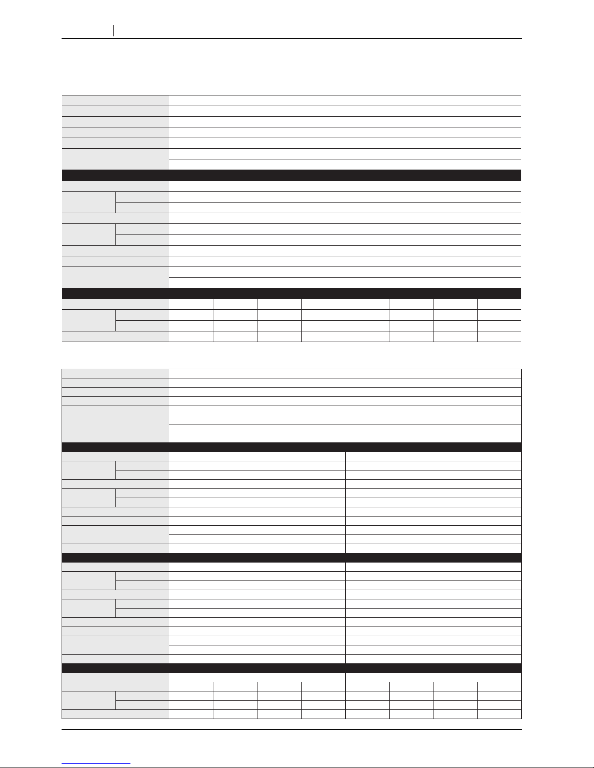
4. Specications
GUG-01SL-E (connection to LGH-50RVX-E or LGH-65RVX-E)
GUG-02SL-E (Connection to LGH-80RVX-E or LGH-100RVX-E)
Refrigerant R410A
Electrical power supply 220-240V / 50Hz, 220V / 60Hz (Supplied from outdoor unit)
Input power Heating / Fan: 2.5W, Cooling: 12.4W
Running current Less than 0.1A
Weight 21kg *Accessories: Approx. 1kg
Function
Heating / Cooling / Auto / Fan
RA (Return Air) temperature control
RA (Return Air) temperature control
Connectable Lossnay unit LGH-50RVX-E LGH-65RVX-E
Capacity [kW]
Heating 6.5 ( 2.4 + 4.1 ) 7.7 ( 3.2 + 4.5 )
Cooling 5.6 ( 2.0 + 3.6 ) 6.6 ( 2.6 + 4.0 )
SHF 0.66 0.69
Performance index
Heating 4.09 4.72
Cooling 4.69 5.03
Air flow range at SP3 and SP4 350 - 695 m3/h 350 - 900 m3/h
Connectable outdoor unit PUHZ-ZRP35 PUHZ-ZRP35
Ext. piping
Diameter Liquid / Gas: 6.35 / 12.7 Diameter Liquid / Gas: 6.35 / 12.7
Maximum length: 50m, Maximum height: 30m Maximum length: 50m, Maximum height: 30m
Ventilation specifications
Fan speed SP4 SP3 SP2 SP1 SP4 SP3 SP2 SP1
Air volume
[m3/h] 500 375 250 125 650 488 325 16 3
[L/s] 139 104 69 35 181 135 90 45
External static pressure [Pa] 105 59 26 7 95 53 24 6
Refrigerant R410A
Electrical power supply 220-240V / 50Hz, 220V / 60Hz (Supplied from outdoor unit)
Input power Heating / Fan: 2.5W, Cooling: 12.4W
Running current Less than 0.1A
Weight 26kg *Accessories: Approx. 1kg
Function
Heating / Cooling / Auto / Fan *Auto is only available for RA temperature control
RA (Return Air) temperature control / SA (Supply Air) temperature control
[Must be set at initial setting and not possible to change from remote controller]
RA (Return Air) temperature control
Connectable Lossnay unit LGH-80RVX-E LGH-100RVX-E
Capacity [kW]
Heating 10.0 ( 4.0 + 6.0 ) 13.2 ( 5.1 + 8.1 )
Cooling 8.3 ( 3.3 + 5.0 ) 11.3 ( 4.2 + 7.1 )
SHF 0.69 0.66
Performance index
Heating 4.62 4.42
Cooling 4.76 4.98
Air flow range at SP3 and SP4 560 - 1200 m3/h 700 - 1200 m3/h
Connectable outdoor unit PUHZ-ZRP50 PUHZ-ZRP71
Ext. piping
Diameter Liquid / Gas: 6.35 / 12.7 Diameter Liquid / Gas: 9.52 / 15.88
Maximum length: 50m, Maximum height: 30m Maximum length: 50m, Maximum height: 30m
Required optional parts PAC-SH30RJ-E and PAC-SH50RJ-E -
SA (Supply Air) temperature control
Connectable Lossnay unit LGH-80RVX-E LGH-100RVX-E
Capacity [kW]
Heating 10.0 ( 4.0 + 6.0 ) 11.4 ( 5.1 + 6.3 )
Cooling 8.3 ( 3.3 + 5.0 ) 9.5 ( 4.2 + 5.3 )
SHF 0.69 0.73
Performance index
Heating 4.62 5.09
Cooling 4.76 5.43
Air flow range at SP3 and SP4 560 - 1200 m3/h 700 - 1200 m3/h
Connectable outdoor unit PUHZ-ZRP50 PUHZ-ZRP50
Ext. piping
Diameter Liquid / Gas: 6.35 / 12.7 Diameter Liquid / Gas: 6.35 / 12.7
Maximum length: 50m, Maximum height: 30m Maximum length: 50m, Maximum height: 30m
Required optional parts PAC-SH30RJ-E and PAC-SH50RJ-E PAC-SH30RJ-E and PAC-SH50RJ-E
Ventilation specifications
Connectable Lossnay unit LGH-80RVX-E LGH-100RVX-E
Fan speed SP4 SP3 SP2 SP1 SP4 SP3 SP2 SP1
Air Volume
[m3/h] 800 600 400 200 1,000 750 500 250
[L/s] 222 167 111 56 278 208 139 69
External static pressure [Pa] 130 73 33 8 130 73 33 8
12
CHAPTER3 Specifications / 4. Specications
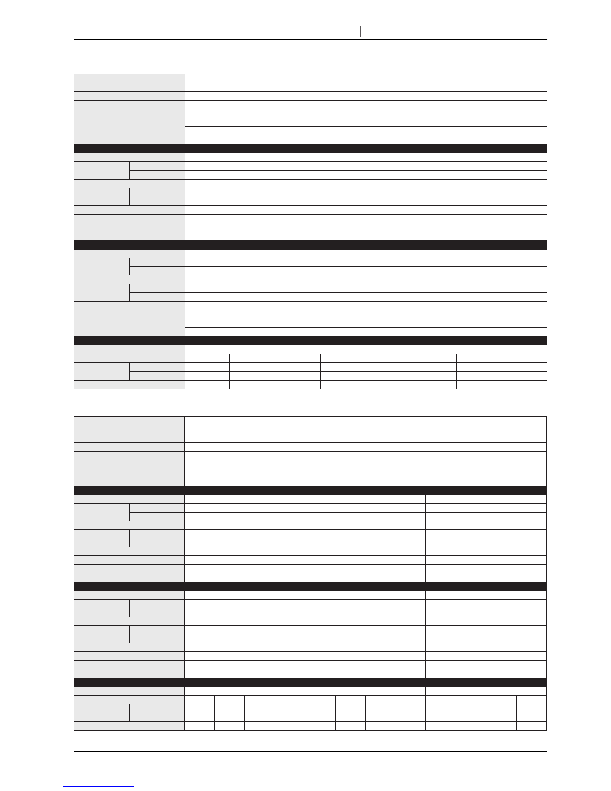
GUG-03SL-E (Connection to LGH-150RVX-E or LGH-200RVX-E)
GUG-03SL-E (Connection to LGH-150RVXT-E, LGH-200RVXT-E or LGH-250RVXT-E)
Refrigerant R410A
Electrical power supply 220-240V / 50Hz, 220V / 60Hz (Supplied from outdoor unit)
Input power Heating / Fan: 2.5W, Cooling: 12.4W
Running current Less than 0.1A
Weight 28kg *Accessories: Approx. 1kg
Function
Heating / Cooling / Auto / Fan *Auto is only available for RA temperature control
RA (Return Air) temperature control / SA (Supply Air) temperature control
[Must be set at initial setting and not possible to change from remote controller]
RA (Return Air) temperature control
Connectable Lossnay unit LGH-150RVX-E LGH-200RVX-E
Capacity [kW]
Heating 20.7 ( 7.7 + 13.0 ) 23.8 ( 10.3 + 13.5 )
Cooling 15.8 ( 6.3 + 9.5 ) 18.4 ( 8.4 + 10.0 )
SHF 0.68 0.76
Performance index
Heating 4.24 5.02
Cooling 5.27 5.86
Air flow range at SP3 and SP4 1050 - 2250 m3/h 1050 - 2600 m3/h
Connectable outdoor unit PUHZ-ZRP100 PUHZ-ZRP100
Ext. piping
Diameter Liquid / Gas: 9.52 / 15.88 Diameter Liquid / Gas: 9.52 / 15.88
Maximum length: 75m, Maximum height: 30m Maximum length: 75m, Maximum height: 30m
SA (Supply Air) temperature control
Connectable Lossnay unit
LGH-150RVX-E
LGH-200RVX-E
Capacity [kW]
Heating
16.6 ( 7.7 + 8.9 )
19.5 ( 10.3 + 9.2 )
Cooling
13.4 ( 6.3 + 7.1 )
15.9 ( 8.5 + 7.4 )
SHF
0.85
0.90
Performance index
Heating 5.46 6.30
Cooling 5.32 5.85
Air flow range at SP3 and SP4 1050 - 2250 m3/h 1050 - 2600 m3/h
Connectable outdoor unit PUHZ-ZRP71 PUHZ-ZRP71
Ext. piping
Diameter Liquid / Gas: 9.52 / 15.88 Diameter Liquid / Gas: 9.52 / 15.88
Maximum length: 50m, Maximum height: 30m Maximum length: 50m, Maximum height: 30m
Ventilation specifications
Connectable Lossnay unit LGH-150RVX-E LGH-200RVX-E
Fan speed SP4 SP3 SP2 SP1 SP4 SP3 SP2 SP1
Air Volume
[m3/h] 1,500 1,125 750 375 2,000 1,500 1,000 500
[L/s] 417 313 208 10 4 556 417 278 13 9
External static pressure [Pa] 150 84 38 9 10 5 59 26 7
Refrigerant R410A
Electrical power supply 220-240V / 50Hz, 220V / 60Hz (Supplied from outdoor unit)
Input power Heating / Fan: 2.5W, Cooling: 12.4W
Running current Less than 0.1A
Weight 28kg *Accessories: Approx. 1kg
Function
Heating / Cooling / Auto / Fan *Auto is only available for RA temperature control
RA (Return Air) temperature control / SA (Supply Air) temperature control
[Must be set at initial setting and not possible to change from remote controller]
RA (Return Air) temperature control
Connectable Lossnay unit LGH-150RVXT-E LGH-200RVXT-E LGH-250RVXT-E
Capacity [kW]
Heating 20.4 ( 7.4 + 13.0 ) 23.8 ( 10.3 + 13.5 ) 26.1 ( 12.1 + 14.0 )
Cooling 15.7 ( 6.2 + 9.5 ) 18.4 ( 8.4 + 10.0 ) 22.3 ( 9.8 + 12.5 )
SHF 0.68 0.76 0.87
Performance index
Heating 4.07 4.86 4.75
Cooling 5.03 5.59 4.59
Air flow range at SP3 and SP4 1050 - 2250 m3/h 1050 - 2600 m3/h 1750 - 2880 m3/h
Connectable outdoor unit PUHZ-ZRP100 PUHZ-ZRP100 PUHZ-ZRP125
Ext. piping
Diameter Liquid / Gas: 9.52 / 15.88 Diameter Liquid / Gas: 9.52 / 15.88 Diameter Liquid / Gas: 9.52 / 15.88
Maximum length: 75m, Maximum height: 30m Maximum length: 75m, Maximum height: 30m Maximum length: 75m, Maximum height: 30m
SA (Supply Air) temperature control
Connectable Lossnay unit LGH-150RVXT-E LGH-200RVXT-E LGH-250RVXT-E
Capacity [kW]
Heating 16.3 ( 7.4 + 8.9 ) 19.5 ( 10.3 + 9.2 ) 21.6 ( 12.1 + 9.5 )
Cooling 13.3 ( 6.2 + 7.1 ) 15.9 ( 8.5 + 7.4 ) 17.6 ( 9.8 + 7.8 )
SHF 0.86 0.90 0.95
Performance index
Heating 5.16 6.01 5.97
Cooling 5.03 5.54 5.31
Air flow range at SP3 and SP4 1050 - 2250 m3/h 1050 - 2600 m3/h 1000 - 2600 m3/h
Connectable outdoor unit PUHZ-ZRP71 PUHZ-ZRP71 PUHZ-ZRP71
Ext. piping
Diameter Liquid / Gas: 9.52 / 15.88 Diameter Liquid / Gas: 9.52 / 15.88 Diameter Liquid / Gas: 9.52 / 15.88
Maximum length: 50m, Maximum height: 30m Maximum length: 50m, Maximum height: 30m Maximum length: 50m, Maximum height: 30m
Ventilation specifications
Connectable Lossnay unit LGH-150RVXT-E LGH-200RVXT-E LGH-250RVXT-E
Fan speed SP4 SP3 SP2 SP1 SP4 SP3 SP2 SP1 SP4 SP3 SP2 SP1
Air Volume
[m3/h] 1,500 1,125 750 375 2,000 1,500 1,000 500 2,500 1,875 1,250 625
[L/s] 4 17 3 13 208 10 4 556 417 278 139 694 521 347 174
External static pressure [Pa] 150 84 38 9 145 82 36 9 14 0 79 35 9
13
CHAPTER3 Specifications / 5. Characteristic curve
Attention
1. The running current and input power are based on 230V/50Hz.
2. The cooling and heating capacities are based on the air conditions listed below and the rated airow of fan speed 4.
Cooling Indoor: 27°CDB/19°CWB Outdoor: 35°CDB/24°CWB
Heating Indoor: 20°CDB/15°CWB Outdoor: 7°CDB/6°CWB
3. The rst gure in ( ) of the capacity specication is the heat recovery energy of the Lossnay unit. The second gure is the
capacity specication for the Dx-coil connected to the outdoor unit.
4. ”Performance index” is the calculated value at the temperature conditions above and is reference purpose only.
Performance index = Total capacity ÷ total power consumption of outdoor unit and Lossnay unit
5. The external static pressure listed above includes the static pressure loss of the Dx-coil unit when using a 50cm straight duct
between the Lossnay and Dx-coil units. When the duct work between the Lossnay and Dx-coil units is longer and/or bent,
the pressure loss of the duct work should be included in the pressure loss calculation.
6. The designed airow of the system (Lossnay, Dx-coil and duct work) at fan speed 3 and 4 should be kept within “Airow range
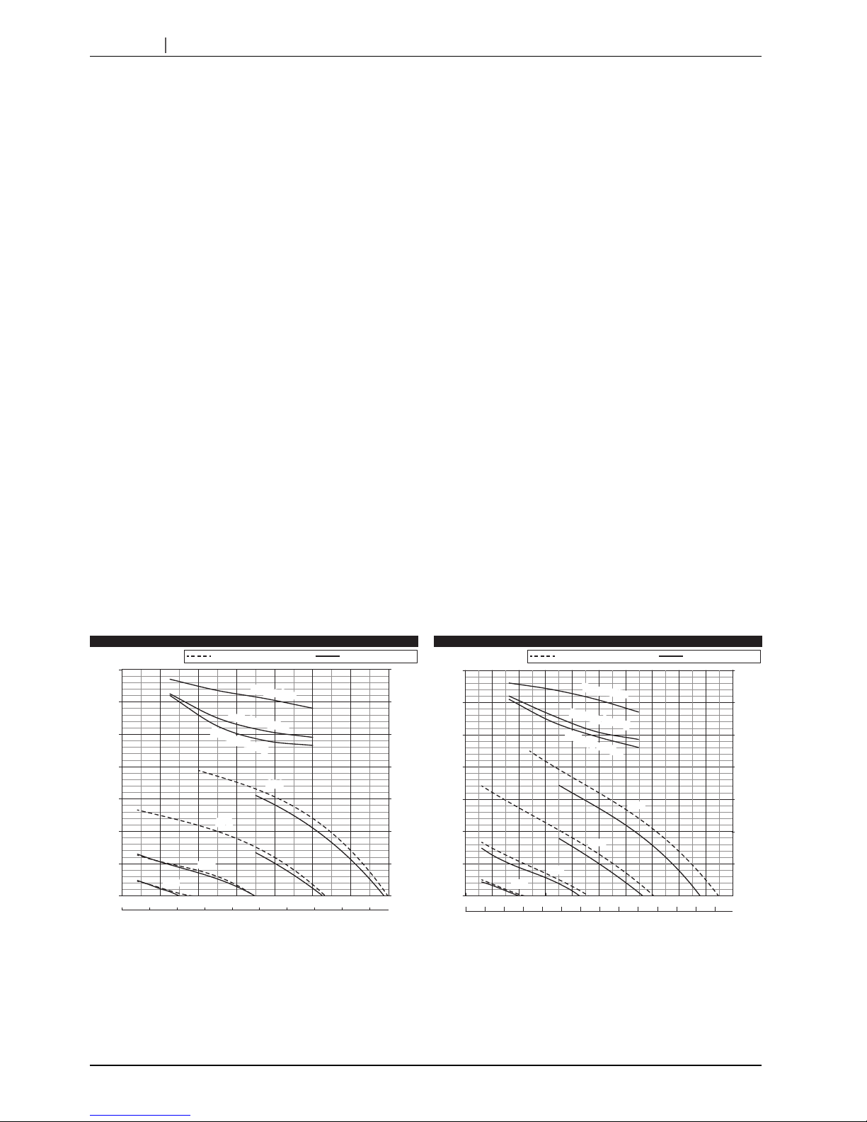
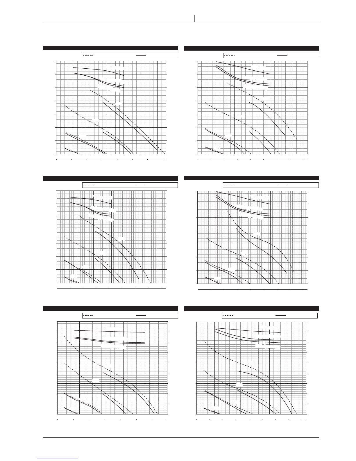
at SP3 and SP4” listed above. This range is shown as the solid line in graphs of the characteristics curve.
If the Lossnay airow is out of this range, the compressor of the outdoor unit may stop for self-protection purposes.
7. By installing the Dx-coil unit with a Lossnay unit, the air blow noise level is quieter at fan speed 4 as shown below.
LGH-50RVX-E: about 4dB quieter, LGH-65RVX-E: about 7dB quieter
LGH-80RVX-E: about 6dB quieter, LGH-100RVX-E: about 7dB quieter
LGH-150,200RVX-E: about 3dB quieter
LGH-150,200RVXT-E: about 3dB quieter, LGH-250RVXT-E: about 4dB quieter
8 .Refrigerant leakage contributes to climate change. Refrigerant with lower global warming potential (GWP) would contribute
less to global warming than a refrigerant with higher GWP, if leaked to the atmosphere.
This appliance contains a refrigerant uid with a GWP equal to 1975. This means that if 1kg of this refrigerant uid would be
leaked to the atmosphere, the impact on global warming would be 1975 times higher than 1kg of CO2, over a period of 100
years. Never try to interfere with the refrigerant circuit yourself or disassemble the product yourself and always ask a professional.
9.
On-site measurements by pitot tube method could be as much 20% difference from JIS test room conditions. If the measuring
point is close to sources of turbulence like bends, contractions and dampers etc., it is difficult to measure air volume correctly.
A straight duct length more than 10D (D=duct diameter or equivalent) from the source of turbulence is recommended for
correct measurement.
On-site measurement should therefore be measured in accordance with BSRIA guideline
(Commissioning Air Systems. Application procedures for buildings AG3/89.3(2001)).
5. Characteristic curve
LGH-50RVX-E
LGH-65RVX-E
0 20 40 60 80 100 120 140 160 180
0 100 200 300 400 500 600 700
Air volume
(m
3
/h)
(L/s)
SP1
SP2
SP3
SP4
Enthalpy cooling
Enthalpy heating
Without GUG-01SL-E With GUG-01SL-E
Temperature
60
70
80
90
Exchange efficiency (%)
0
50
100
150
200
250
300
350
Static pressure (Pa)
Air volume
Without GUG-01SL-E With GUG-01SL-E
(m3/h)
(L/s)
0 20 40 60 80 100 120 140 160 180 200 220 240 260
0 100 200 300 400 500 600 700 800 900 1000
SP1
SP2
SP3
SP4
Enthalpy cooling
Enthalpy heating
Temperature
0
50
100
150
200
250
300
350
Static pressure (Pa)
60
70
80
90
Exchange efficiency (%)
Following gures show air volume drop when connecting Dx-coil unit.
The air ow range is limited because of the protection for overload of outdoor unit when Dx-coil unit is connected.
14
CHAPTER3 Specifications / 5. Characteristic curve
LGH-80RVX-E
LGH-100RVX-E
0 50 100 150 200 250 300 350
0 200 400 600 800 1000 1200
Without GUG-02SL-E With GUG-02SL-E
(m3/h)
(L/s)
Air volume
SP1
SP2
SP3
SP4
Enthalpy cooling
Enthalpy heating
Temperature
60
70
80
90
Exchange efficiency (%)
0
50
100
150
200
250
300
350
Static pressure (Pa)
0 50 100 150 200 250 300 350 400
0 500 1000 1500
Air volume
Without GUG-02SL-E With GUG-02SL-E
(m3/h)
(L/s)
SP1
SP2
SP3
SP4
Enthalpy cooling
Enthalpy heating
Temperature
60
70
80
90
Exchange efficiency (%)
0
50
100
150
200
250
300
350
Static pressure (Pa)
LGH-150RVX-E
0 100 200 300 400 500 600 700 800
0
500 1000 1500 2000 2500 3000
Air volume
Without GUG-03SL-E With GUG-03SL-E
SP1
SP2
SP3
SP4
Enthalpy cooling
Enthalpy heating
Temperature
60
70
80
90
Exchange efficiency (%)
0
50
100
150
200
250
300
350
Static pressure (Pa)
(m3/h)
(L/s)
LGH-200RVX-E
0 100 200 300 400 500 600 700 800
0 500 1000 1500 2000 2500 3000
Air volume
Without GUG-03SL-E With GUG-03SL-E
SP1
SP2
SP3
SP4
Enthalpy cooling
Enthalpy heating
Temperature
60
70
80
90
Exchange efficiency (%)
0
50
100
150
200
250
300
350
Static pressure (Pa)
(m
3
/h)
(L/s)
LGH-150RVXT-E
0 100 200 300 400 500 600
0 500 1000 1500 2000 2500
Air volume
0
50
100
150
200
250
300
350
450
400
Without GUG-03SL-E With GUG-03SL-E
SP1
SP2
SP3
SP4
Enthalpy cooling
Enthalpy heating
Temperature
Exchange efficiency (%)
60
70
80
90
Static pressure (Pa)
(m
3
/h)
(L/s)
LGH-200RVXT-E
0 100 200 300 400 500 600 700 800
0 500 1000 1500 2000 2500 3000
Air volume
Without GUG-03SL-E With GUG-03SL-E
SP1
SP2
SP3
SP4
Enthalpy cooling
Enthalpy heating
Temperature
0
50
100
150
200
250
300
350
450
400
Exchange efficiency (%)
60
70
80
90
Static pressure (Pa)
(m3/h)
(L/s)
LGH-100RVX-E
15
CHAPTER3 Specifications / 5. Characteristic curve
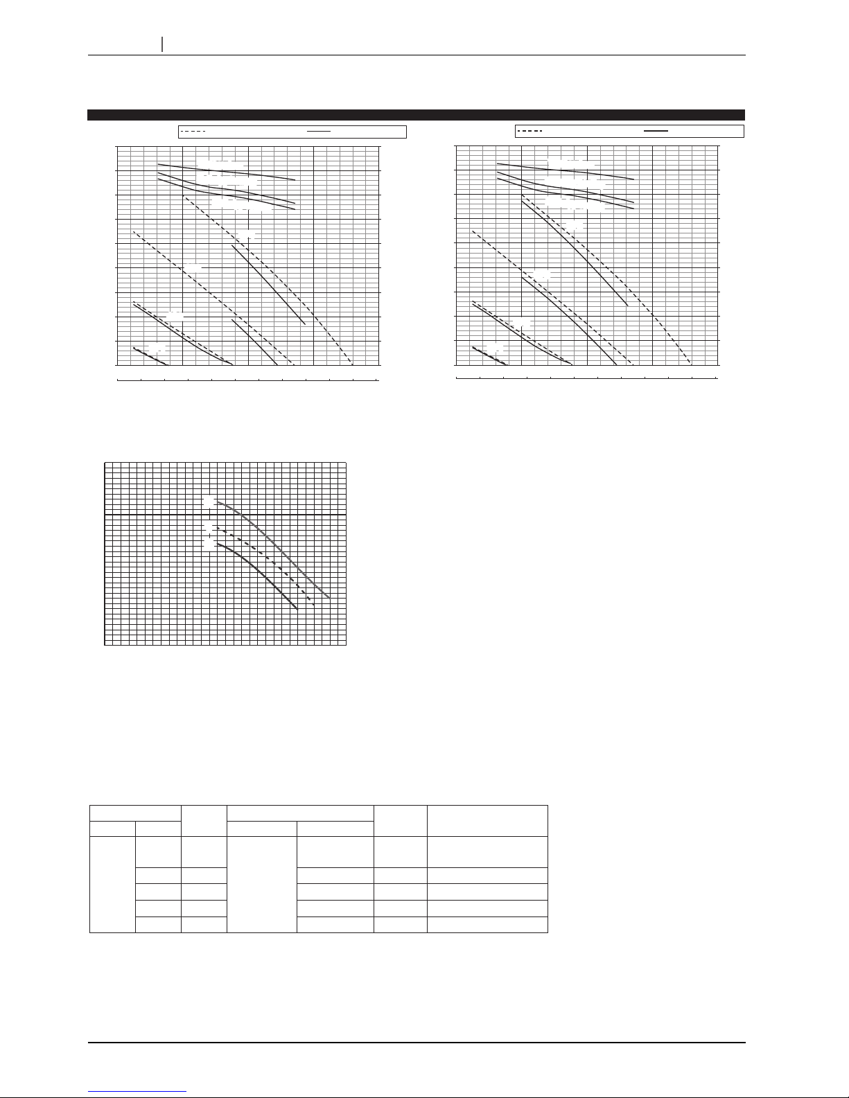
LGH-250RVXT-E
0 100 200 300 400 500 600 700 800 900 1000 1100
0 1000 2000 3000 4000
Air volume
Without GUG-03SL-E
RA temperature control
With GUG-03SL-E
SP1
SP2
SP3
SP4
Enthalpy cooling
Enthalpy heating
Temperature
Exchange efficiency (%)
60
70
80
90
0
50
100
150
200
250
300
350
450
400
Static pressure (Pa)
(m3/h)
(L/s)
0 100 200 300 400 500 600 700 800 900 1000 1100
0 1000 2000 3000 4000
Air volume
Without GUG-03SL-E
SA temperature control
With GUG-03SL-E
SP1
SP2
SP3
SP4
Enthalpy cooling
Enthalpy heating
Temperature
Exchange efficiency (%)
60
70
80
90
0
50
100
150
200
250
300
350
450
400
Static pressure (Pa)
(m3/h)
(L/s)
[Reference information]
P-Q curve image
1. Lossnay unit
2. Lossnay unit + Dx-coil unit
3. Lossnay unit (fan power up +4) + Dx-coil unit
Static pressure (Pa)
Air volume (m3/h)
3
3
1
1
2
2
Recovery of static pressure losing by Dx-coil unit.
*This graph is just for illustrative purposes.
When connecting Dx-coil unit to Lossnay unit, the original Lossnay P-Q curve (Curve.1) will decrease because of adding
pressure loss by Dx-coil unit (Curve.2).
One solution to recover this static pressure decrease is setting fan power up function of Lossnay unit (Curve.3).
This fan power up function is only available when Lossnay remote controller PZ-61DR-E is used.
Select adequate setting data number which is associated with fan power up level shown in below table at the function setting
page of PZ-61DR-E.
Refer to Lossnay and PZ-61DR-E installation manual for more detailed information.
DIP-SW
Setting
check
PZ-61DR-E
Setting
check
Supply fan power up
SW No. Setting Function No. Setting data
N/A
- -
55
0
(Factory setting)
N/A
- - 1 1 level up
- - 2 2 level up
- - 3 3 level up
- - 4 4 level up
16
CHAPTER4
Outlines and Dimensions
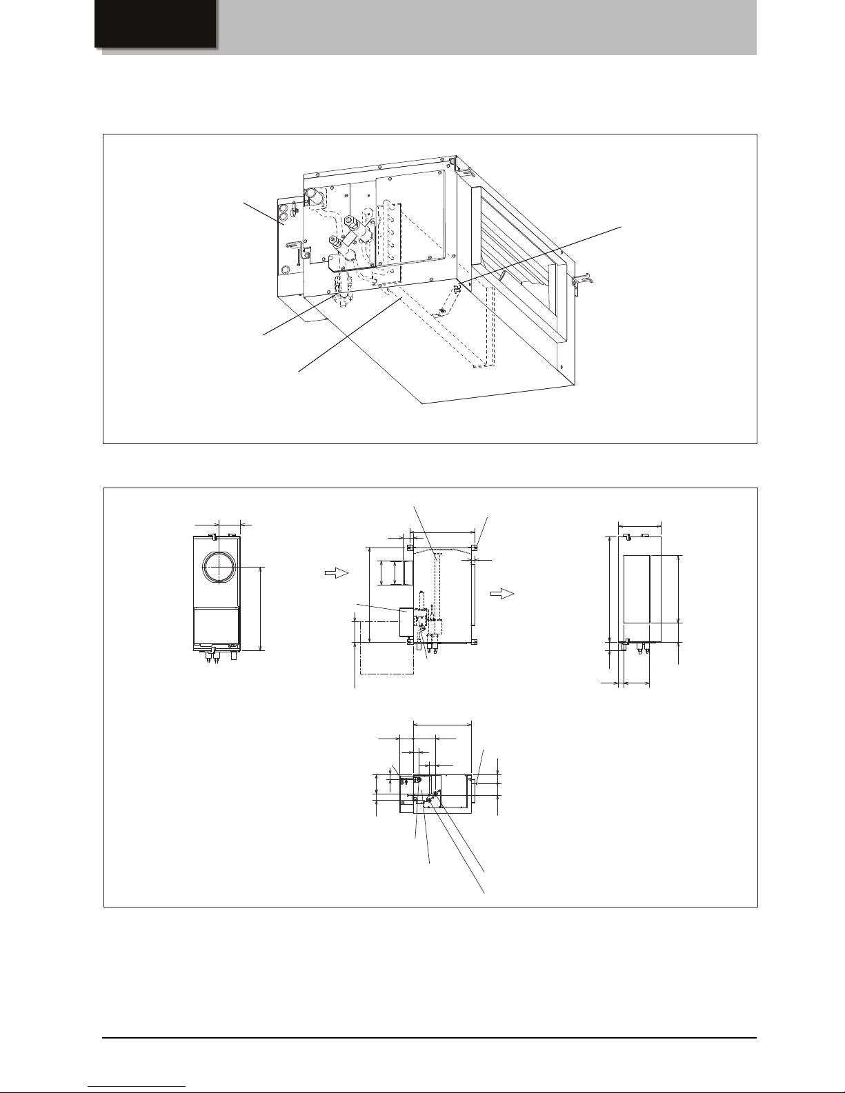
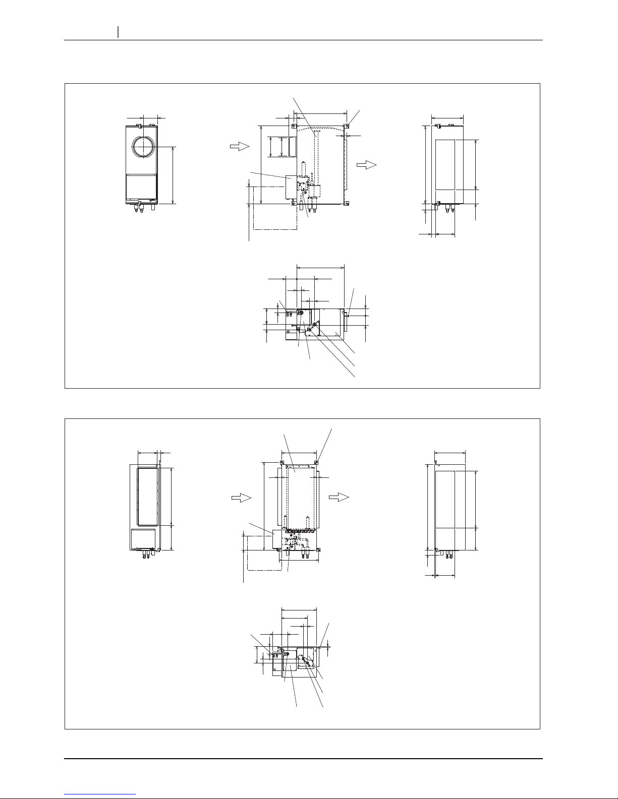
1. Outlines and dimensions
GUG-01SL-E
Names of the parts
Heat exchanger
Drain pump
Control box Supply air thermistor
(Only for GUG-02 and 03SL-E)
Note:
The drain pump always runs in the cooling mode and continues to run for six minutes after the unit stops.
63
593
30
492
85
146
166
812
330
φ208
φ192
520
200
41
551
147
Air inlet from
Lossnay
115 186
55
100 77
52
44
47
An inspection opening is required
for installation and regular
maintenance (check) of the drain
pump.
811
Unit (mm)
Ceiling suspension
fixture
Liquid pipe φ6.35
Gas pipe φ12.7Maintenance cover for drain pump, inlet air
thermistor and water sensor
Heat exchanger
Control box
150 to 200
Drain pump
Drain pipe (O.D φ32)
Inspection
opening
450 x 450 or
more
SA
(supply air)
Ceiling suspension fixture
(4-13 X 20 oval)
Power supply
cable opening
17
CHAPTER4 Outlines and Dimensions / 1. Outlines and dimensions
GUG-02SL-E
GUG-03SL-E
63
600
30
492
84
132
207
1034
394
φ258
φ242
750
25059
551
170
Air inlet from
Lossnay
115 186
55
165 56
52
86
47
An inspection opening is required for
installation and regular maintenance
(check) of the drain pump. When SA
temp. control is selected, another
inspection opening may be required in
front of the unit for SA thermistor
replacement only when an error
occurred on the SA thermistor.
1033
Ceiling suspension
fixture
Liquid pipe φ9.52
Gas pipe φ15.88Maintenance cover for drain pump, inlet air
thermistor and water sensor
Heat exchanger
Control box
150 to 200
Drain pump
Drain pipe (O.D φ32)
Inspection
opening
450 x 450 or
more
SA
(supply air)
Ceiling suspension fixture
(4-13 X 20 oval)
Power supply
cable opening
Maintenance cover for SA thermistor
Unit (mm)
An inspection opening is required for
installation and regular maintenance
(check) of the drain pump. When SA
temp. control is selected, another
inspection opening may be required in
front of the unit for SA thermistor
replacement only when an error
occurred on the SA thermistor.
Ceiling suspension
fixture
Liquid pipe φ9.52
Gas pipe φ15.88
Maintenance cover for drain pump, inlet air
thermistor and water sensor
Heat exchanger
Control box
150 to 200
Drain pump
Drain pipe (O.D φ32)
Inspection
opening
450 x 450
or more
Ceiling suspension fixture
(4-13 X 20 oval)
Power supply
cable opening
Maintenance cover for SA thermistor
Air inlet from
Lossnay
SA
(supply air)
63
217
518
1130
49
14 250
290
250 47
461
750329
750
1156
30
459
97
404
14
52
115
340
55
78
Unit (mm)

18
CHAPTER4 Outlines and Dimensions/ 2. Installation example
2.1 GUG-01SL-E and GUG-02SL-E
2. Installation example
Note:
•The distance between the Lossnay unit
and the Dx-coil unit must be between 25
cm and 5 m when the duct is straight.
•The length of the connection cable
(enclosed accessory) between the
Lossnay and Dx-coil units is about 6 m.
Please install the two units so that the
cable can be connected.
Note:
•The duct between the two units can
be bent like the gure.
* To take the control cover off.
Top view (to install straight duct)
Side view (to install with straight duct)
Side view (to minimize the space with slope duct)
Top view (to install with bent duct)
Connection cable
(Enclosed accessory)
Connection cable
(Enclosed accessory)
Duct (Field supply)
Duct (Field supply)
Min 150*

19
CHAPTER4 Outlines and Dimensions/ 2. Installation example
Note:
•The distance between the Lossnay unit
and the Dx-coil unit must be between 25
cm and 5 m when the duct is straight.
•The length of the connection cable
(enclosed accessory) between the
Lossnay and Dx-coil units is about 6 m.
Please install the two units so that the
cable can be connected.
Note:
•The distance between the Lossnay unit
and the Dx-coil unit must be between 25
cm and 5 m when the duct is straight.
•The length of the connection cable
(enclosed accessory) between the
Lossnay and Dx-coil units is about 6 m.
Please install the two units so that the
cable can be connected.
2.2 GUG-03SL-E with LGH-150/200RVX-E
Side view (with chamber box)
Following duct works is example using chamber box between LGH-150/200RVX-E and GUG-03SL-E.
Top view (with chamber box)
Top view (to install with rectangular duct)
2.3 GUG-03SL-E with LGH-150/200/250RVXT-E
Connection cable
(Enclosed accessory)
Duct (Field supply)
Connection cable (Enclosed accessory)
Chamber box (field supply)
Rectangular duct (field supply)
Duct
(field supply)
20
CHAPTER5
Wiring Diagram
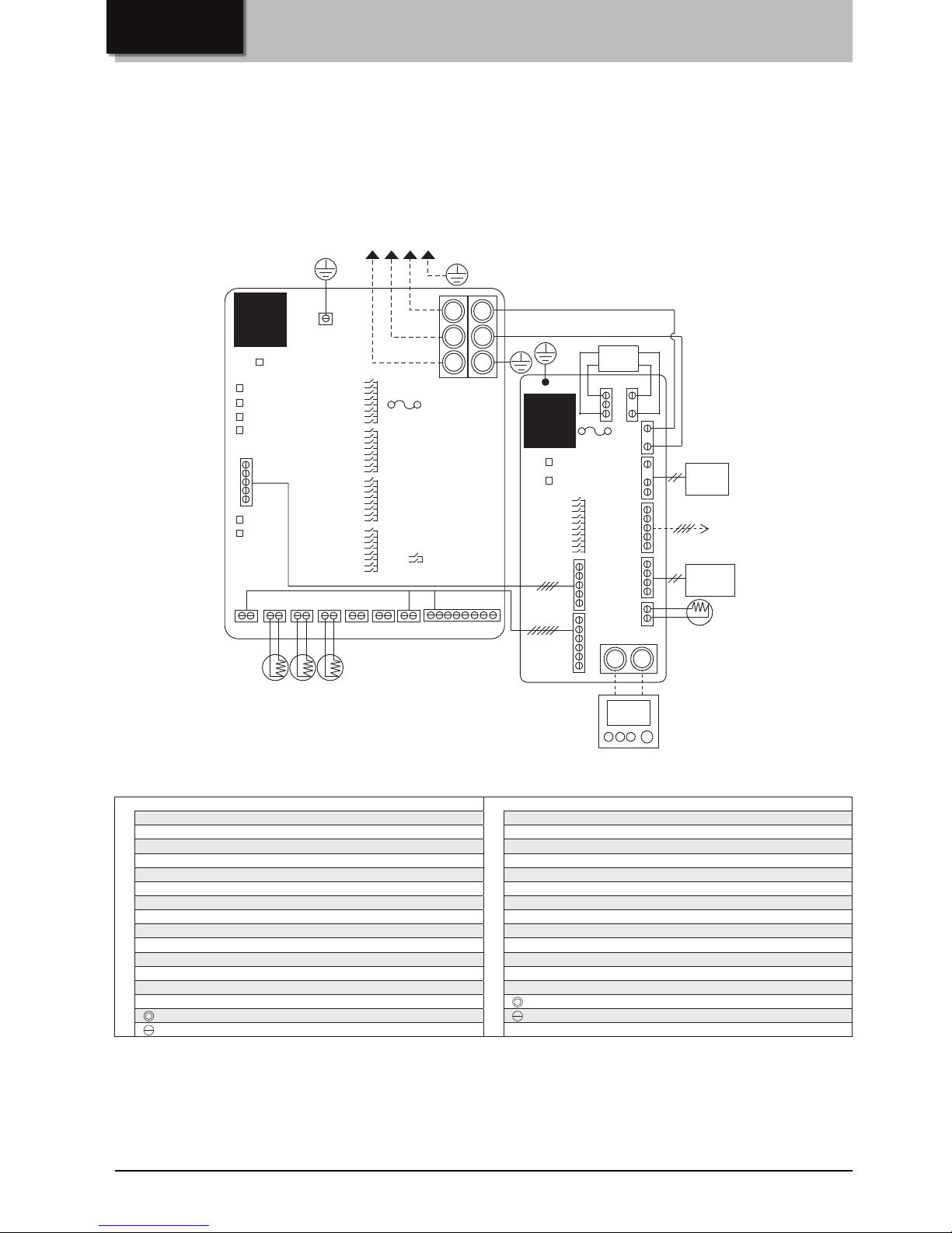
1. Wiring diagram
Note:
1. TB6, TM104 and CN120 shown in dotted lines are eld work.
2. Make sure to connect the ground wire.
3. Prior to access the electrical parts cut off the power supply (all to Dx-coil unit, Lossnay unit and outdoor unit) more than ve
minutes.
4. The appliance shall be installed in accordance with national wiring regulations.
Printed circuit board A Printed circuit board B
TB6 : Terminal for power supply from the outdoor unit TM104 : Terminal for remote controller PZ-01RC
TAB1 : Connector (Ground) SW11 : Switch (Function selection)
SW1-SW4 : Switch (Function selection) LED11 : Inspection indicator lamp
SW6 : Switch (Function selection) LED12 : Power supply indicator lamp
LED1 : Power supply indicator lamp CN1 : Connector (Power supply)
LED2-5 : Operation status CN2 : Connector (Transformer primary)
LED6, 7 : Reading or writing data to SD card CN3 : Connector (Drain pump)
CN105 : Connector (IT communication) CN4 : Connector (Transformer secondary)
CN20 : Connector (TH1, software use) CN5 : Connector (IT communication)
CN21 : Connector (TH2, liquid pipe temp.) CN6 : Connector (Output to PCB A)
CN22 : Connector (Remote controller) CN9 : Connector (TH9, supply air temp.)
CN23 : Connector (TH11, inlet air temp.) CN10 : Connector (Water sensor)
CN29 : Connector (TH5, gas pipe temp.) CN120 : Connector (Communication to Lossnay)
CN82 : Connector (Forced comp. OFF)
: Terminal block
: Terminal block
: Connector on PCB
: Connector on PCB
Denition of symbols
Attention
1.With this product, the wiring installation method will vary according to the design of the system.
2.Perform electrical installation to meet local electrical regulations.
3.Always use double insulated PVC cable for the transmission cables.
4.Wiring work must be performed by qualied professionals.
CN105
LED1
S1
L
N
E
S2
S3
TB6
CN9
CN10
CN120
CN3
CN2CN4
CN6
CN5
CN1
SW11
TM104
LED12
LED11
SW1
SW6
TAB1
CN20
CN23 CN21 CN29
CN22 CN82
TH11
TH2
TH5
SW2
SW3
SW4
LED5
LED4
LED3
LED2
LED6
LED7
TH9
SA thermistor
(GUG-02 and GUG-03SL-E)
Dedicated remote controller PZ-01RC
(Enclosed accessory)
To Lossnay
(CN20)
(RED)
(RED)
CN20:RED
CN23:BROWN
CN29:BLACK
CN22:BLUE
Others: WHITE
(RED)
(YELLOW)
(WHITE)
(WHITE)
(WHITE)
(GREEN)
To outdoor unit
Printed
Circuit
Board B
Printed
Circuit
Board A
TRANS
DRAIN
PUMP
WATER
SENSOR
* PZ-61DR-E cannot be connected.
Fuse 15 A 250 V
Fuse
5 A 250 V
 Loading...