

Repair work must be performed by
the manufacturer, its service agent or
a similarly qualified person in order to
avoid hazards.
June 2014 No. U189-A
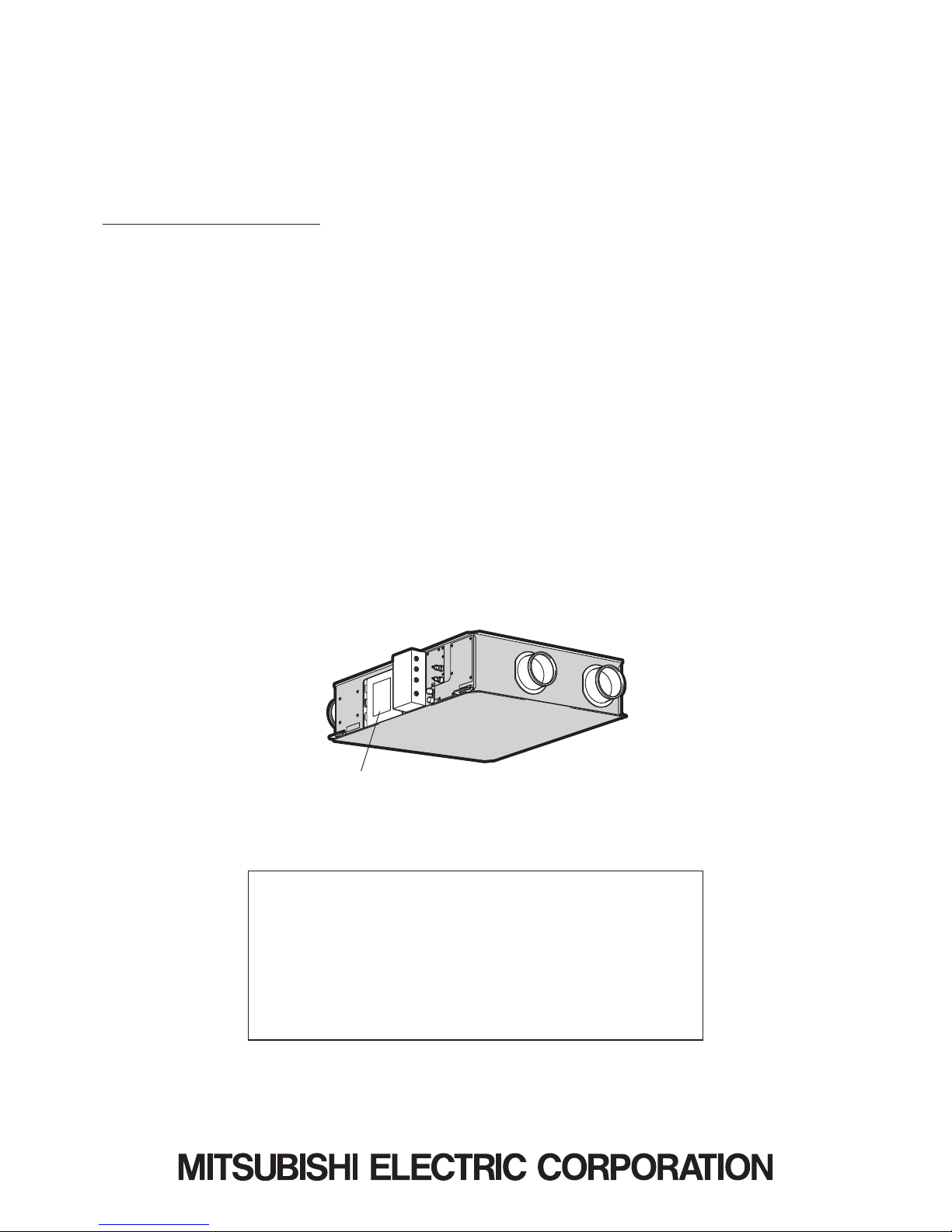
Model : GUF-50RD4
GUF-50RDH4
GUF-100RD4
GUF-100RDH4
GUF-100RDH4-60
FRESH MASTER
HANDBOOK
Nameplate

Contents
1. Safety precautions
....................................................................
3-4
2. Names and functions of components
..........................................
4
3. Specifications
..............................................................................
5
4. Outside dimensions
.....................................................................
6
5. Electrical wiring diagrams
.........................................................
7-8
6. Circuit board diagrams
...........................................................
9-10
7. Troubleshooting
.....................................................................
11-17
8. Overhauling procedures
........................................................
18-28
9. Parts catalog
........................................................................
29-63
GUF-50RD
4
...................................................................
30-35
GUF-50RDH
4
.................................................................
36-41
GUF-100RD
4
.................................................................
42-47
GUF-100RDH
4
...............................................................
48-55
GUF-100RDH
4-60
..........................................................
56-63
─ 3 ─
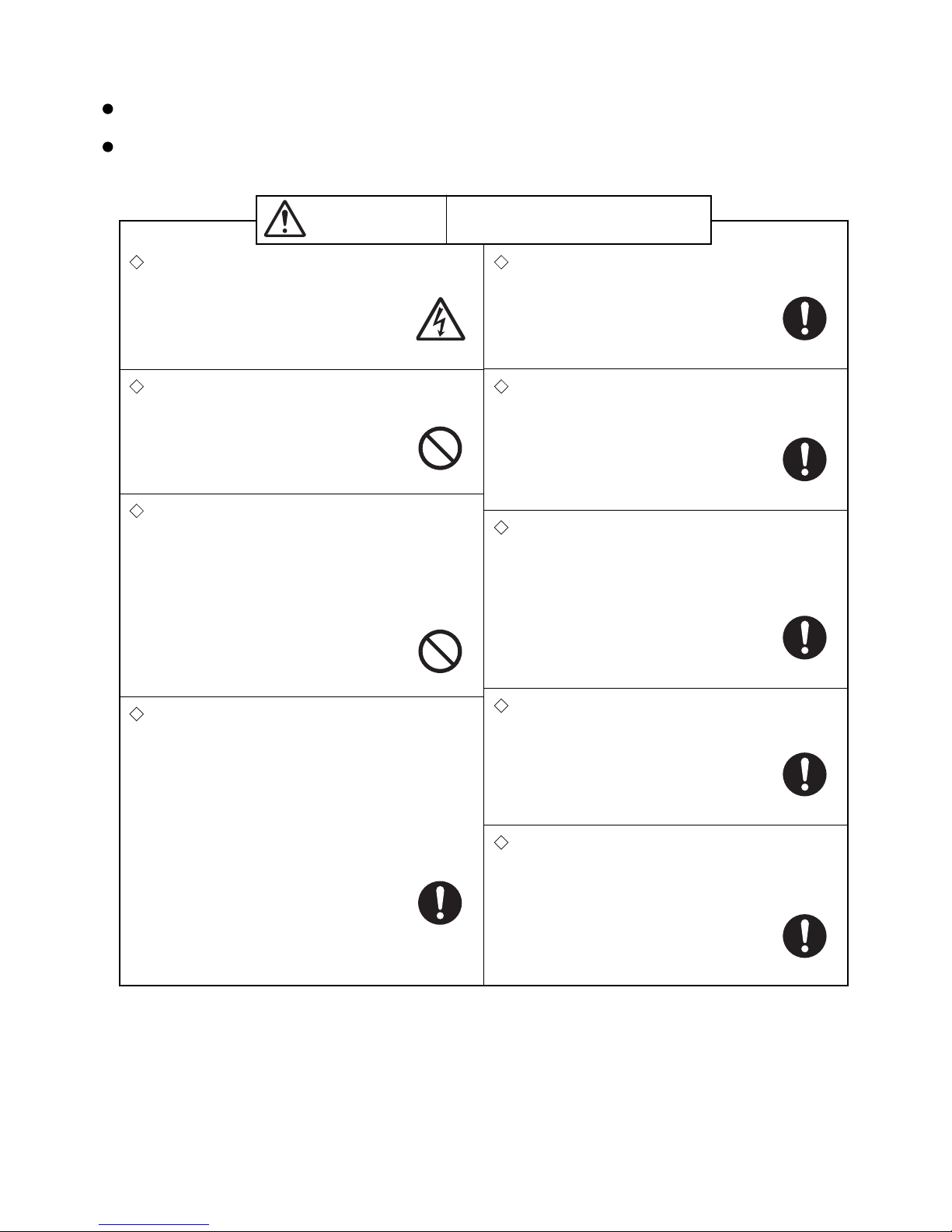
1. Safety precautions
Warning
Modification is prohibited
Do not modify the unit.
(Failure to heed this warning may result
in electric shock, fire and/or injury.)
Electric shock
If you must inspect the circuitry while the power is
on, do not touch the live parts.
(Failure to heed this warning may result
in electric shock.)
Check insulation
Upon completing repair work, always measure the
insulation resistance. Verify that it is at least 10 MΩ
(with a 500 V DC insulation resistance tester), and
then turn on the power.
(Inadequate insulation may result in
electric shock.)
Incorrect handling of the product may
result in serious injury or death.
Do not mix anything other than the specified
coolant of the same type used in the outdoor
unit.
Do not charge any coolant different from the coolant
used in the outdoor unit.
(
Failure to heed this warning may cause
the pressure inside the freezing cycle
to become abnormally high, leading to
injury or other damage.
)
Use proper parts and tools
For repair, be sure to use the parts listed in the
service parts list of the applicable model and use the
proper tools.
(Failure to heed this warning may result in
electric shock, fire and/or injury.)
Caution against
electric shock
Prohibited
Turn off the power supply
Be sure to shut off the power supply isolator before disassembling the unit for repair.
(Failure to heed this warning may result
in electric shock.)
Be sure to follow
this instruction.
Be sure to follow
this instruction.
Be sure to follow
this instruction.
Read the following precautions thoroughly before the maintenance, and then inspect and repair the product in a
safe manner.
The types and levels of danger that may arise if the product is handled incorrectly are described with the warning
symbols shown below.
Toxic gas generation
• Be careful that the coolant (R407C, R410A) does
not leak in a flammable environment.
• Conduct welding operation in an open room.
• If the coolant gas leaks, open the windows while
servicing.
• Be sure to completely repair the leak. Close the
service valve if the repair work is temporarily suspended.
(
If the coolant gas comes into contact
with flames such as open fire, sparks
and a heater, it may generate toxic gas.
)
Be sure to follow
this instruction.
Prohibited
Proper electric work
Use the electric wires designated for electric work, and
conduct electric work in accordance with the "Electric
Installation Engineering Standard", the "Indoor Wiring
Regulations", and the Installation Instructions.
(Improper connection or wiring installation
may result in electric shock and/or fire.)
Be sure to follow
this instruction.
Replace damaged and/or degraded parts
Be sure to replace the power-supply cord and lead
wires if they are damaged and/or degraded.
(Failure to heed this warning may result in
electric shock and/or fire.)
Be sure to follow
this instruction.
─ 4 ─
Make sure that the product operates properly upon completing repair work. Clean the product and the surround-
ing area, and then notify the customer of the completion of repair.
Request for repair
Inspect the earth condition, and repair it if it is incomplete. Make sure that an earth leakage breaker or an
overload protection device is installed. If it is not installed, recommend the dealer to install one.
Caution
Incorrect handling of the product may result in injury or
damage to properties including buildings and equipment.
Caution for injury
Do not work at a location where you do not have a
sure footing.
( Failure to heed this caution may result in
a fall.)
Wear gloves
Wear gloves when servicing.
(Failure to heed this caution may result in
injury to your hands from sharp metal or
other edges.)
Be sure to follow
this instruction.
Prohibited
Prevent water leakage
• Before removing any of the water-related parts,
completely drain the residual water from the piping.
• Upon completing repair work, be sure to check the
drainage of the indoor unit and that no water leaks
from any of the piping connections.
(Water leakage may cause buildings to
soil, leading to secondary failure of other
parts.)
Be sure to follow
this instruction.
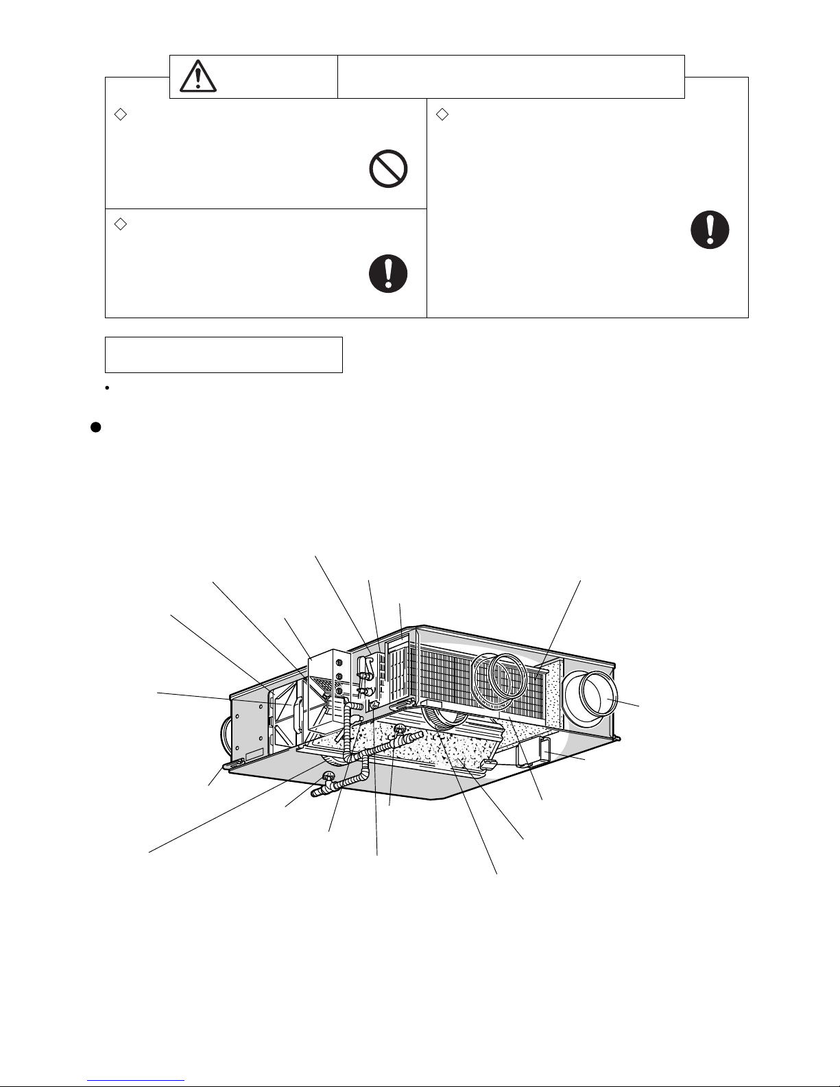
2. Names and functions of components
Lossnay core
Temperature and humidity
are exchanged between
supply air and exhaust air.
High efficiency filters (Optional parts)
Removes dust from the outside air.
Damper plate
Switches between the Lossnay
ventilation and normal ventilation.
Air filter
Prevents clogs in the Lossnay core
*The illustration shows GUF-50RDH4.
Control box
Maintenance cover
Ceiling suspension fixture
Exhaust fan
Fan used to expel dirty air to outside of the room
Direct expansion coil
Heats or cools the air supply after heat exchange.
Electronic expansion valve
Maintenance cover (for humidifying)
Permeable-film humidifier
Performs clean humidifying of the air supply
after heat exchange.
Not available on GUF-50/100RD4 types
Discharge valve
Drain discharge hole
Service valve
Strainer (O-ring installed)
Air supply fan
Fan to supply outside air to the inside
Water supply tube
Supplies water to the permeable-film humidifier.
Duct connection flange
─ 5 ─
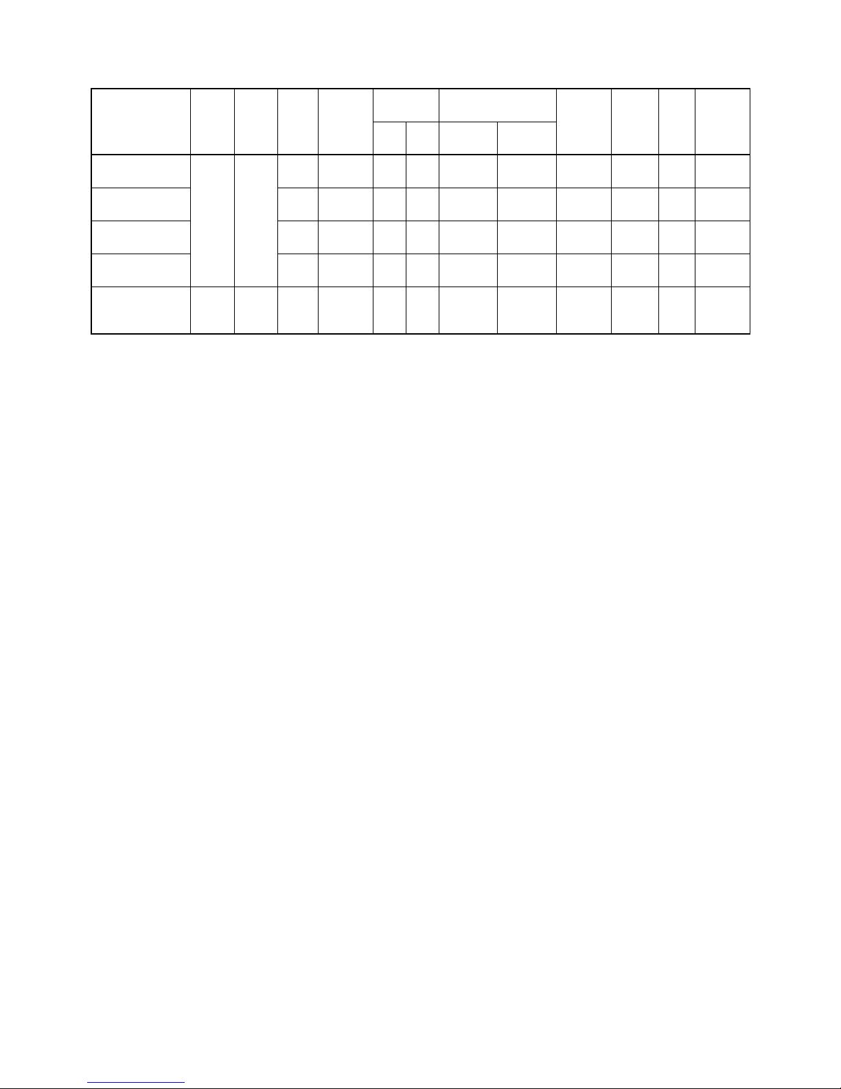
3. Specifications
• The values given in the table for the noise level reflect the levels measured at a position 1.5 meters immediately
below the unit in an anechoic chamber.
• The noise at the air outlets (at a 45° angle, 1.5 meters in front) is about 5-6 dB (A) higher than the values given in
the table.
• The above values apply during Lossnay ventilation when the fan speed is set to high speed.
* Capability in ( ) is heat recovery capability by the Lossnay cores.
Cooling/Heating capability indicates the maximum value at operation under the following condition.
Cooling: Indoor: 27°C DB/19°C WB Outdoor: 35°C DB/24°C WB
Heating: Indoor: 20°C DB/13.8°C WB Outdoor: 7°C DB/6°C WB
• Mitsubishi Electric measures products according to Japan Industrial Standard (JIS B 8628).
• In the United Kingdom, on-site measurements by pitot tube method could be as much 20% different from JIS test
room conditions. If the measuring point is close to sources of turbulence like bends, contractions and dampers,
etc., it is difficult to measure the air volume correctly. A straight duct length more than 10D (D=duct diameter) from
the source of turbulence is recommended for correct measurement. On-site measurement should therefore be
carried out in accordance with BSRIA guideline (Commissioning Air Systems. Application procedures for buildings
AG3/89.3 (2001)).
Model name
Power
supply
(V)
Frequency
(Hz)
Current
(A)
Power con-
sumption
(W)
Air volume
External air load heat
processing capability (kw)
Humidifying
volume
Noise
(dB)
Weight
(kg)
Equivalent
indoor unit
capability
m3/h L/S
Cooling
capability
Heating
capability
GUF-50RD
4
Single-
phase
220-240
50
1.15 235-265 500 139
5.57
(1.94)
6.21
(2.04)
-
33.5-34.5
54 P32
GUF-50RDH
4 1.15 235-265 500 139
5.57
(1.94)
6.21
(2.04)
2.70
33.5-34.5
57 P32
GUF-100RD
4 2.20 480-505
1,000
278
11.44
(4.12)
12.56
(4.26)
- 38-39 92 P63
GUF-100RDH
4 2.20 480-505
1,000
278
11.44
(4.12)
12.56
(4.26)
5.40 38-39 98 P63
GUF-100RDH
4-60
Single-
phase
220
60 3.20 685
1,000
278
11.44
(4.12)
12.56
(4.26)
5.40 40.5 98 P63
─ 6 ─
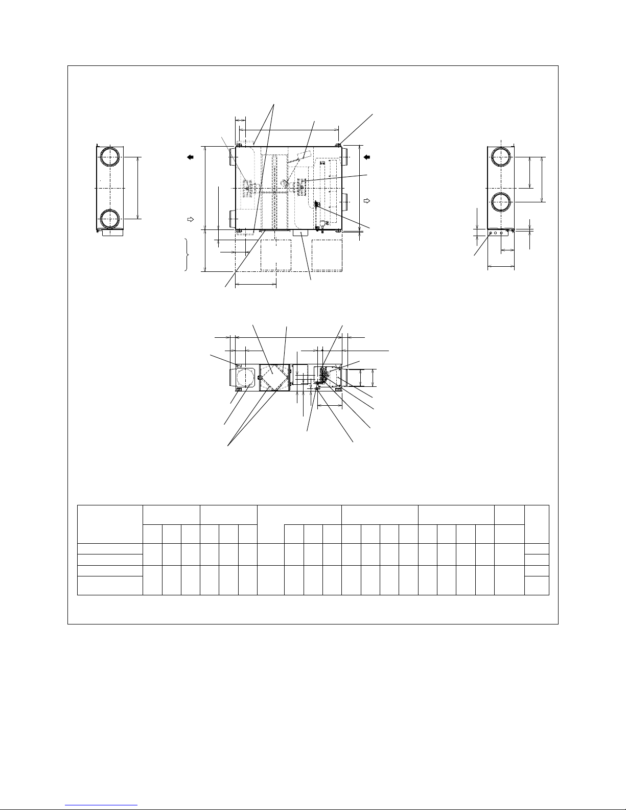
4. Outside dimensions
GUF-50RD4, GUF-50RDH4, GUF-100RD4, GUF-100RDH4, GUF-100RDH4-60
G
P
M
L
20
100
øH
øJ
C
(N)
A
F
E
N
D
B
79
79
N
T
150 to 250
60
Q
79
R
30
K
Air exhaust fan
Damper plate
Air supply fan
Ceiling suspension fixture
(4×13×30 length hole for GUF-50 types)
(4×15×30 length hole for GUF-100 types)
RA
(Return air)
Control box
Maintenance cover
EA
(Exhaust air)
Gas pipe
Drain discharge hole
(VP25 connection)
Lossnay core
Liquid pipe
Heat exchanger
Air filters
SA
(Supply air)
OA
(Outdoor air)
Ceiling suspension fixture
Maintenance cover
Location at which the duct direction can be changed
Lossnay core
Air filter
High efficiency filter
Fan
Maintenance space
Inspection
opening
Inspection
opening
Solenoid valve unit with
pressure regulator*
Solenoid valve
Heat exchange unit
Humidifying element
Maintenance space
Power cable
installation port
Upper location at which the ceiling
suspension fixture can be installed
(for GUF-100 types)
Location at which the duct direction
can be changed
Humidifying element*
S (Water intake)
(Discharge hole)
Water intake strainer
with check valve*
(PT1/2 External thread)
More than 600
(The components marked with * are available for GUF-50/100RDH4 types only)
High efficiency filter
(Optional part)
Model
External
dimension
Ceiling suspen-
sion
fi xture pitch
Duct connection
fl ange
Duct pitch Humidifi cation
Inspection
opening
Weight
(kg)
ABCDEF
Nominal
diameter
GH J K LMNPQR S T
GUF-50RD
4
1288 1016
317 1185
1048
22 200
158.5
192 208 745
372.5
435 124 347 135 99 266 450
54
GUF-50RDH
4 57
GUF-100RD
4
1580 1231
398
1465 1271
16 250 199 242 258 920 460 670 149 361 169 110 280 600
92
GUF-100RDH
4
GUF-100RDH4-60
98
Unit (mm)
─ 7 ─
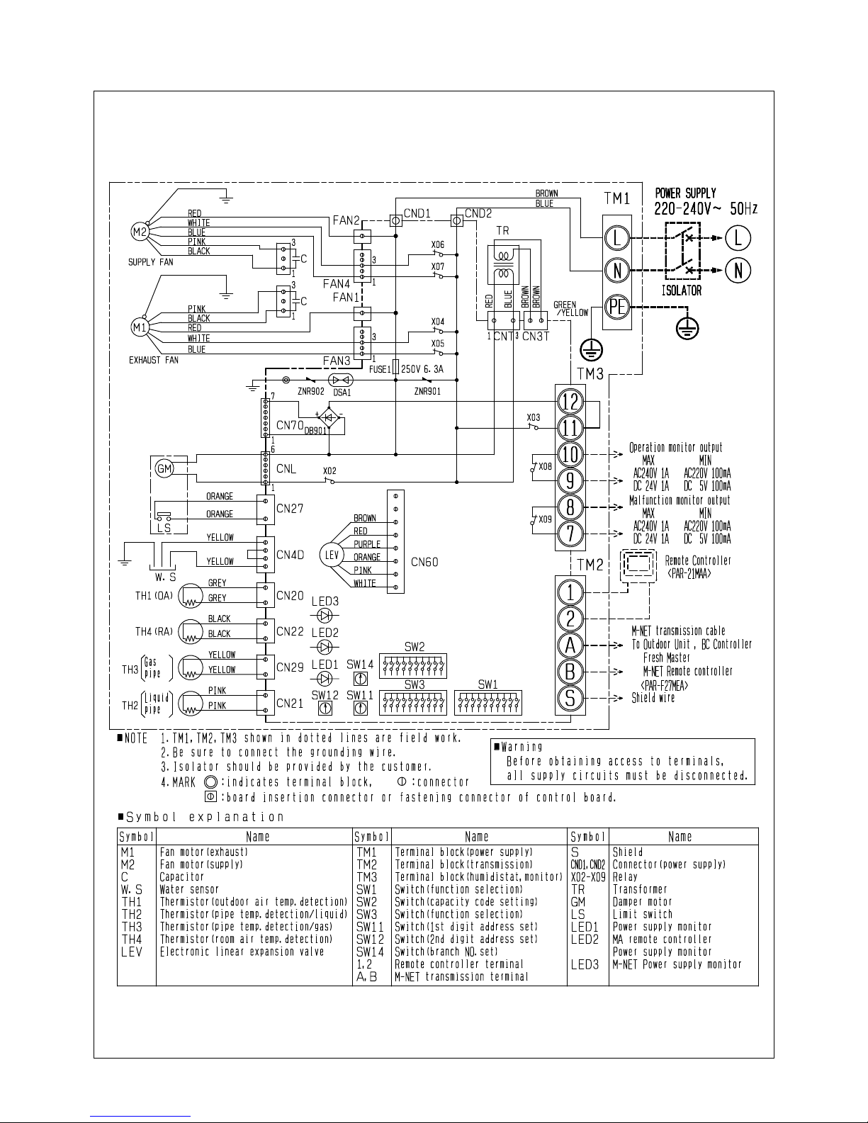
5. Electrical wiring diagrams
GUF-50RD4, GUF-100RD4
─ 8 ─
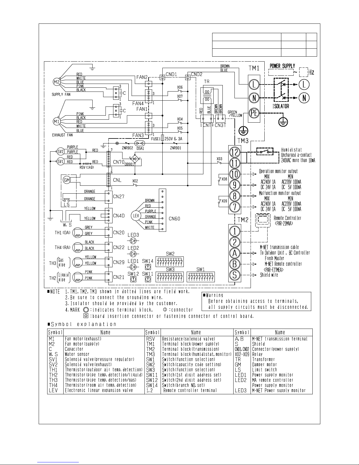
GUF-50RDH4, GUF-100RDH4, GUF-100RDH4-60
AB
AB
GUF-50RDH
4, GUF-100RDH4 220-240 V 50
GUF-100RDH
4-60 220 V 60
─ 9 ─
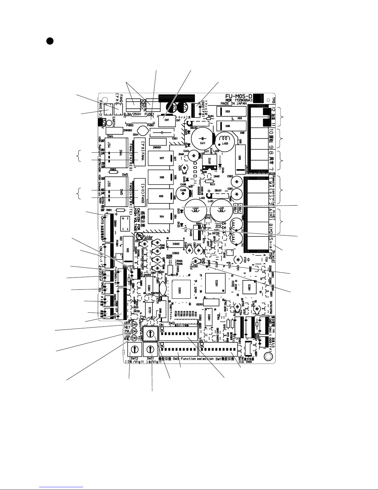
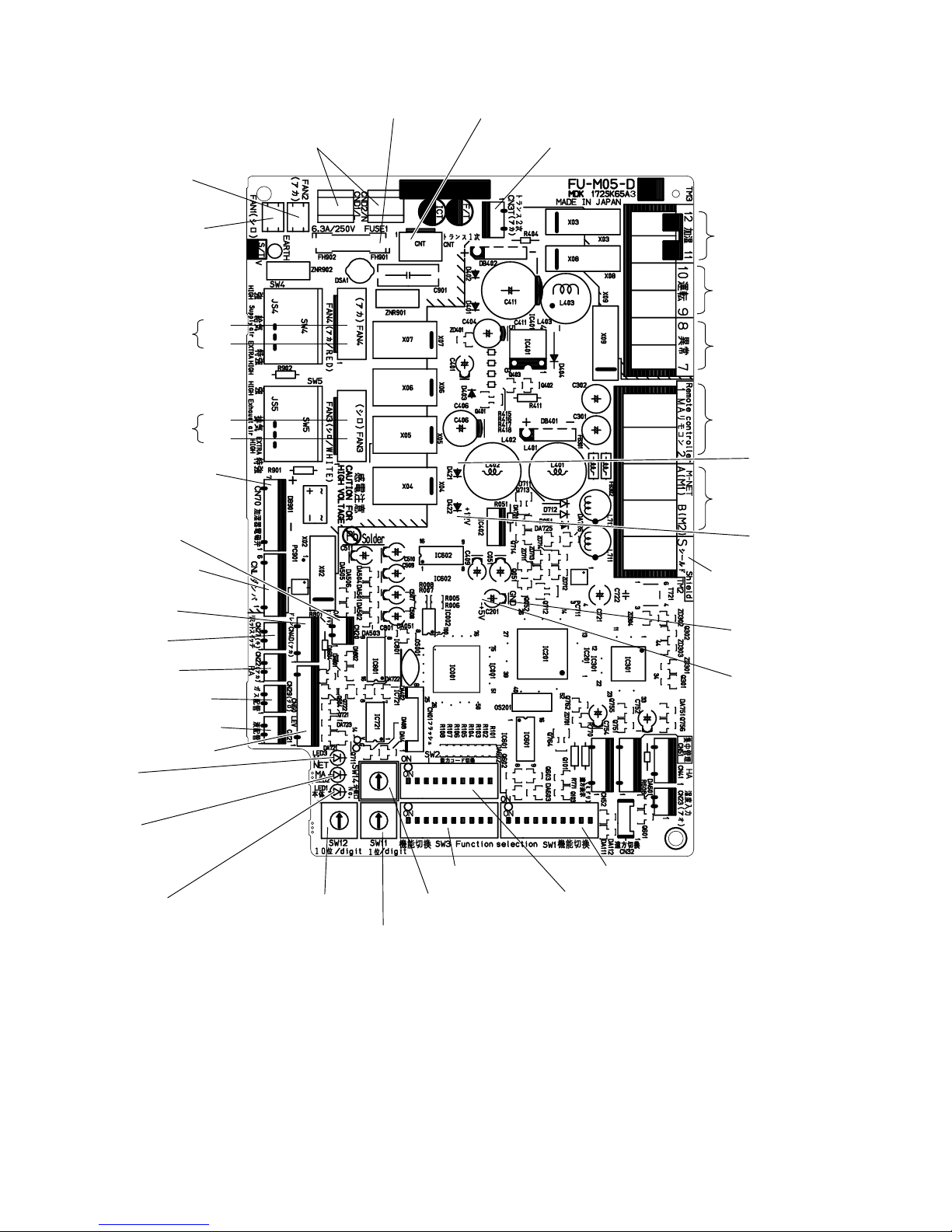
6. Circuit board diagrams
Circuit board diagrams and check points <FU-M05-D4>
1 GUF-50RD4, GUF-50RDH4, GUF-100RD4, GUF-100RDH4
LEV
Power supply
220-240 V AC 50 Hz
14 V DC
12 V DC
5 V DC
GND
External humidifier
control input
Operation monitor output
ZKHQVWRSSHG
GXULQJRSHUDWLRQ
MA remote controller
transmission cable
M-NET
transmission cable
M-NET
transmission cable
6KLHOGHGSDUW
Error monitor output
QRUPDOO\
when there is an error
Supply fan
&RPPRQ
Fuse
$9 7UDQVIRUPHUSULPDU\LQSXW
7UDQVIRUPHUVHFRQGDU\RXWSXW
16 to 23 V AC
KLJK
low
OA thermistor
Damper motor
220-240 V AC 50 Hz
Limit switch
RA thermistor
Gas pipe thermistor
Water sensor
Liquid pipe thermistor
LED3
On when M-NET line
power is on.
LED1
On when power is on.
Exhaust fan
&RPPRQ
Supply fan
220-240 V AC
50 Hz
KLJK
low
Exhaust fan
220-240 V AC
50 Hz
Solenoid value
Full-wave rectified YROWDJH
of 220-240 V AC 50 Hz
(GUF-50/100RDH
4W\SHV
LED2
On when MA remote
controller power is on.
Address switch
7HQVGLJLW
Address switch
2QHVGLJLW
Branch No. switch
Function switch 3
Function switch 2
Function switch 1
─ 10 ─
2 GUF-100RDH4-60
LEV
14 V DC
12 V DC
5 V DC
GND
External humidifier
control input
MA remote controller
transmission cable
M-NET
transmission cable
M-NET
transmission cable
(Shielded part)
Supply fan
(Common)
Fuse
(6.3 A/250 V)
OA thermistor
Limit switch
RA thermistor
Gas pipe thermistor
Water sensor
Liquid pipe thermistor
LED3
On when M-NET line
power is on.
LED1
On when power is on.
Exhaust fan
(Common)
LED2
On when MA remote
controller power is on.
Address switch
(Tens digit)
Address switch
(Ones digit)
Branch No. switch
Operation monitor output
ZKHQVWRSSHG
GXULQJRSHUDWLRQ
Error monitor output
QRUPDOO\
when there is an error
)
Function switch 3
Function switch 2
Function switch 1
high
low
high
low
Transformer primary (input)
Transformer secondary (output)
16 to 23 V AC
Power supply
220 V AC 60 Hz
Damper motor
220 V AC 60 Hz
Supply fan
220 V AC
60 Hz
Exhaust fan
220 V AC
60 Hz
Solenoid value
Full-wave rectified voltage
of 220 V AC 60 Hz
─ 11 ─
7. Troubleshooting
Work precautions
• When servicing, be sure to recreate the malfunction two or three times before starting repairs.
• When servicing, always keep proper footing.
• When servicing, make sure that the power supply isolator is off, so as no electrical shock or injury to occur.
Pay sufficient attention when working on the product.
• Always connect the power wires properly.
• When removing the circuit board, always hold it at both ends and remove carefully so as not to apply force
to the surface mounted parts.
• When removing the circuit board, be careful of the metal edges on the board.
• When removing or inserting the connectors for the circuit board, hold the entire housing section. Never pull
on the lead wires.
• If it is thought that there is a printed circuit board malfunction, check for disconnected wires in the print pattern, burnt parts or discoloration.
• If the printed circuit board is replaced, make sure that the switch settings on the new board are the same as
the old board.
• When servicing or checking around the humidifying unit, make sure to close the service valve.
(1)
Troubleshooting 1: The system will not start properly.
Initialization checklist from installation to operation (Table 1
)
After checking the system, check the checkpoints listed below.
Power supply (Table 1-1
)
Transmission cables (Table 1-2)
Check the following checkpoints when connecting with the remote controller or M-NET controller.
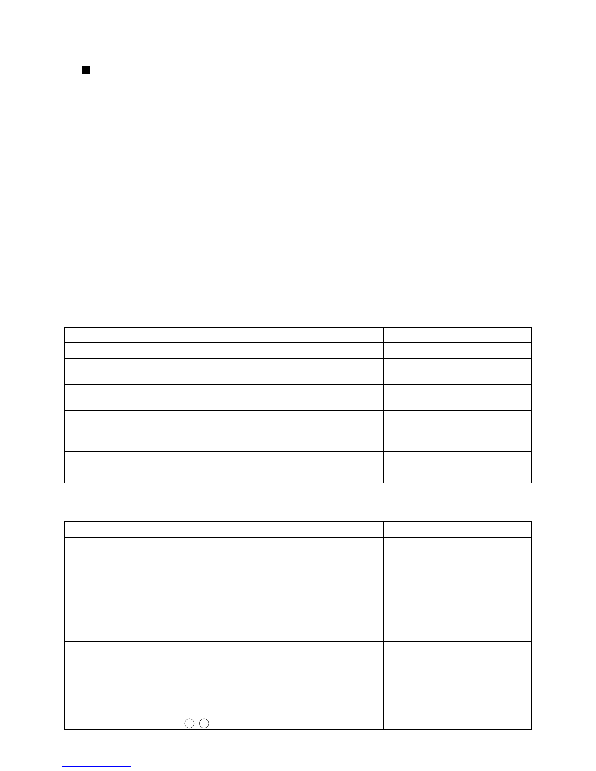
No. Checkpoint Action
1 Is the main power supply on? Turn on the main power supply.
2 Do the main power supply switching capacity and wiring diameter meet
specification?
Use specified items.
3 Is the specified power supply of 220 to 240 V AC (220 V AC for GUF-
100RDH4-60) connected to the power supply terminal (TM1)?
Connect the specified power supply.
4 Has the fuse (FUSE 1) on the circuit board blown? Replace the circuit board.
5
Are connector CNT of the transformer primary (input) and connector CN3T of
the transformer secondary (output) on the circuit board securely connected?
Connect them securely.
6
Is the power supply wiring incorrectly wired, or is there a faulty connection?
Make secure connections.
7 Is power display LED1 (red) on the circuit board unlit? Check the above checkpoints.
No. Checkpoint Action
1 Do the transmission cables meet regulations? (Type, diameter
)
Use specified cables.
2 Is the transmission cable wired at least 5 cm away from the power supply
cable?
Wire the transmission cable at least 5
cm away from the power supply cable.
3 Are multiple transmission or signal cables wired to the same power cable
duct?
Wire the transmission cables away
from the signal cables.
4 Are multiple transmission cables wired with multi-core cables? Use suitable cables to wire the
transmission cables so that they
are separated from one another.
5 Are the transmission cables securely connected to the terminals? Connect them securely.
6 Are the address switches on the circuit board (SW11 and SW12) set to
the correct number?
Make the setting so that the address does not duplicate that of
other devices within M-NET control.
7 Are the transmission cables connected to the specified terminal blocks?
MA remote controller: TM2 1, 2
M-NET controller: TM2
A
,
B
Connect them to the specified
terminal blocks.
─ 12 ─
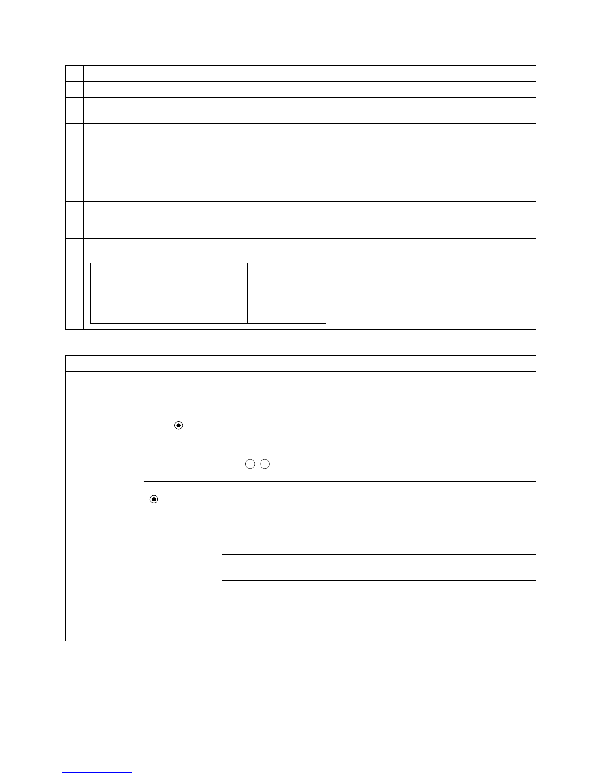
Signal cables to external devices (Table 1-3)
Check the following checkpoints when outputting the operation monitor and malfunction monitor.
No. Checkpoint Action
1 Do the signal cables meet regulations? (Type, diameter
)
Use specified cables.
2
Is the signal cable wired at least 5 cm away from the power supply cable?
Wire the signal cable at least 5 cm
away from the power supply cable.
3 Are multiple transmission or signal cables wired to the same power cable
duct?
Wire the transmission cables away
from the signal cables.
4 Are multiple signal cables wired with multi-core cables? Use suitable cables to wire the
signal cables so that they are separated from one another.
5 Are the signal cables securely connected to the terminals? Connect them securely.
6 Are the signal cables connected to the specified terminal blocks?
Operation monitor: TM3 9, 0
Malfunction monitor: TM3 7, 8
Connect them to the specified
terminal blocks.
7 Are the output capacities of the operation monitor and malfunction moni-
tor within the ratings?
Output Maximum rating Minimum rating
Operation monitor 240 V AC, 1 A
24 V DC, 1 A
220 V AC, 100 mA
5 V DC, 100 mA
Malfunction monitor 240 V AC, 1 A
24 V DC, 1 A
220 V AC, 100 mA
5 V DC, 100 mA
Use them within the ratings.
State of machine Remote controller Cause Remedy
Does not operate. • Remote control-
ler display does
not appear.
•
The power display “
” does
not appear on
the remote controller.
(When
PAR-21MAA is used)
Power is not supplied to Fresh
Master, or power that does not follow
specifications is used.
Check the power supply to Fresh
Master. (Refer to Table 1-1
)
Is there a connection of 3 or more remote controllers, or 16 or more Fresh
Master units?
Check the number of units connected.
The remote controller is connected to
TM2 A , B (terminal block for M-NET
transmission cable).
Connect the transmission cable
to TM2 1, 2.
The power display
“
” does not
appear on the
remote controller
when power is
supplied to the
system.
(When
PAR-F27MEA is
used)
The power of the outdoor unit is not
turned on.
ME remote controller is powered by
the outdoor unit. Turn on the power
of the outdoor unit.
Power is not supplied to the transmission cable that connects indoor
units and an outdoor unit.
Check the settings of the outdoor
unit. See the City Multi databook for
details.
Faulty connection of the
M-NET
transmission cable
See Table 1-2.
The number of Fresh Masters, indoor
units, or remote controllers connected to the transmission cable exceeds
the power supply capacity of the
outdoor unit.
Connect Fresh Masters, indoor units,
or remote controllers within the pow-
er supply capacity of the outdoor unit.
See the City Multi databook for de-
tails.
(
Table 2
)

─ 13 ─
State of machine Remote controller Cause Remedy
Does not operate. The power display
“
” does not
appear on the
remote controller
when power is
supplied to the
system.
(When
PAR-F27MEA is
used)
When a power supply unit is used:
1
The power supply unit is not connected with the transmission cable.
2 The power supply unit is not
turned on.
3
The length of the M-NET transmission cable wiring from the power
supply unit is longer than specified
(longer than 200 m).
1
Connect the power supply unit with
the transmission cable.
2
Check the power of the power supply unit.
3
Check the length of the transmission cable wiring. (See the technical
manual for details about the regula-
tions.)
The transmission cable power supply
restrictions have been exceeded.
Make connections within the transmission cable power supply restrictions of
the outdoor units, or the power supply
units. (See the technical manual for
details about the restrictions.)
Cool air or warm
air does not come
out.
The LCD screen
shows that it is in
operation.
The restart protection delay circuit is
in operation for 3 minutes.
Wait for a while.
(To protect the compressor, a 3
minutes delay circuit is built into the
OA processing unit. Therefore, some-
times the compressor will not start
operating immediately. This delay
may be up to 3 minutes.)
OA processing unit operation has
restarted following the heating and
defrosting operation.
Wait for a while.
(Heating operation starts after de-
frosting operation has ended.)
It runs briefly, but
soon stops.
The
CHECK
and
check code flashes on the LCD
screen.
The air inlet or outlet of the OA processing unit and/or outdoor unit is
obstructed.
Restart after removing the obstruction.
The filters are clogged with dust and
dirt.
Restart after cleaning the filters.
Does not humidify.
(GUF-50/100RDH4
types only)
—
The OA processing unit is not set to
the “
heating” mode.
Set to the heating mode.
Water is not supplied. Open the service valve.
Dry mode cannot
be set from the
remote controller.
—
There is no dry mode on the OA processing unit. Cannot set to dry mode
from the remote controller.
When the unit is set to dry mode from
the central controller, the dry mode
display flashes on the LCD and the
OA processing unit fan operates.
Use a mode other than dry mode.
Dry mode can be
set from the central controller, but
does not operate.
Dry mode display
is flashing in LCD.
─ 14 ─
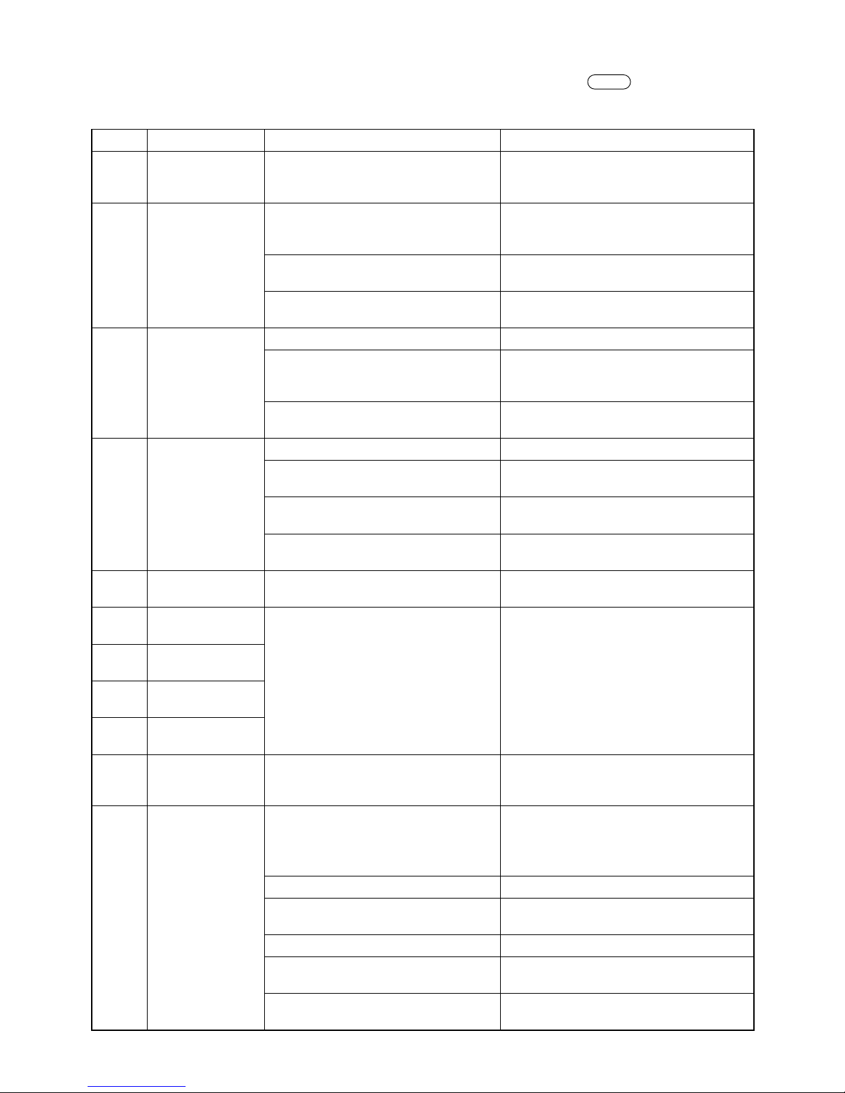
(2) Troubleshooting 2: An error code is displayed on the remote controller.
See below for possible remedies when there is an error during test operation and
CHECK
followed by a 4-digit
number is displayed on the remote controller.
Note: The components marked with * are available for GUF-50/100RDH4 types only.
Error code
Error content Cause Remedy
0900 Test run Is the test operation switch of either the
fan, bypass damper, or humidifier solenoid valve* turned ON?
Set the test operation switch (SW1-1, 7,
8*) to OFF.
2600 Drain error Drain water is not properly discharged. The body must be levelly installed.
The drain pipe must be installed with a
gradient of more than 1/100.
Is there a leak from the permeable-film
humidifier*?
• Fix the water leak.
• Replace the humidifier element*.
When no problem is found after checking the above items.
Replace the circuit board.
2601 Disconnected
water sensor connector
Is the CN4D connector firmly connected?
Firmly connect the connector.
Is the relay connector between the
circuit board and water sensor firmly
connected?
Firmly connect the connector.
When no problem is found after checking the above item.
Replace the circuit board.
3602 Damper motor
error
Is the CNL connector firmly connected? Firmly connect the connector.
Is the connector of the damper motor
section firmly connected?
Firmly connect the connector.
Does the damper operate when the
damper motor is running?
Replace the damper motor if it is not work-
ing.
When no problem is found after checking the above items.
Replace the circuit board.
4116 Fan motor error The motor continues to run when the
operation is stopped.
Replace the circuit board.
5101 Indoor temperature
sensor error
• Are the connectors of each thermistor
firmly connected?
• Is each relay connector firmly con-
nected?
• When no problem is found after
checking the above item.
• Firmly connect each connector.
• Firmly connect each connector.
• Replace the circuit board.
5102 Liquid pipe temper-
ature sensor error
5103 Gas pipe tempera-
ture sensor error
5104 Outdoor tempera-
ture sensor error
6600 Indoor unit address
setting error
There are duplicate address settings,
meaning there are indoor units with the
same address.
Check the addresses of devices in the
system.
6602 Communication
error (Transmission
processor H/W
error)
Any of the transmission cables of the
indoor units, Fresh Master, or outdoor
units was wired, or the polarity was
changed with the power ON.
Simultaneously turn OFF the power of the
indoor units, Fresh Master, and the outdoor
units, and then, turn them ON again.
Specified power supply is not used. Check the power supply.
Earth fault in the transmission cable Check the transmission cable wiring and
shielding.
The setting of the outdoor unit is incorrect.
See the service manual of the outdoor unit.
Transmission data was changed due to
noise in the transmission cable line.
Inspect the transmission waveform and
noise in the transmission cable line.
Malfunction of a controller for the device
in which the error occurs.
If the controller is normal, it is a malfunc-
tion of the circuit board.
─ 15 ─
Error code
Error content Cause Remedy
6603 Communication er-
ror (Bus busy error
in the transmission
line)
The transmission processor cannot
transmit data because short-period voltages such as noise continuously occurs
in the transmission cable line.
Inspect the transmission waveform and
noise in the transmission cable line.
Malfunction of a controller for the device
in which the error occurs.
If the controller is normal, it is a malfunc-
tion of the circuit board in Fresh Master.
Replace the circuit board.
6606 Communication
error (Handshake
error)
Data was not transmitted correctly due
to an accidental misoperation of the
controller for the device in which the
error occurs.
Simultaneously turn OFF the power of the
indoor units, Fresh Master, and the outdoor
units, and then, turn them ON again.
Malfunction of a controller for the device
in which the error occurs.
If the same error occurs again, it is a mal-
function of the circuit board in the device in
which the error occurs.
6607 Communication er-
ror (No ACK error)
(Only when the error occurs in Fresh
Master.)
Single coolant system
1 The address has been changed in
midstream.
2 Improper wiring or disconnection of
the transmission cable
3 Malfunction of the controller
4 Malfunction of the remote controller
(When the switch (SW3-1) is ON)
Simultaneously turn OFF the power of the
outdoor units and Fresh Master, and then,
turn them ON again.
In the case of the accidental malfunction,
the unit returns to normal.
If the unit does not return to normal, check
the causes 1 to 4.
Group operation system with multiple
coolant lines
1 The above causes 1 to 4
( When Fresh Master is interlocked
with the indoor units in the different
coolant line)
2 Short circuit or disconnection of the
transmission cable to the terminal
block for central control (TB7) in the
outdoor unit
3 The outdoor unit in one of the cool-
ant lines is shut down.
4 The setting of the outdoor unit is
incorrect.
If the error occurs after the unit operates normally, the following can be
caused.
• Total capacity error (7100)
• Capacity code setting error (7101)
• The number of connected devices er-
ror (7102)
• Address setting error (7105)
Simultaneously turn OFF the power of the
outdoor units and Fresh Master, and then,
turn them ON again.
In the case of the accidental malfunction,
the system returns to normal.
If the system does not return to normal,
check the causes 1 to 4.
If none of the above causes applies, check
the error display LEDs of the other remote
controllers or outdoor units.
• When there is an error
See the error code, and repair troubled
sections according to the instructions
described in the troubleshooting.
• When there is no error
It is a malfunction of the circuit board in
Fresh Master.
See the service manual of the outdoor unit.
─ 16 ─
Error code
Error content Cause Remedy
6607 Communication er-
ror (No ACK error)
System connected with MELANS
a) Malfunction only in some of the units
• Refer to the causes for the single
coolant system
Refer to the remedy for the single coolant
system
b) Malfunction in all the indoor units and
Fresh Master units in one coolant
line
1 Causes of total capacity error
(7100)
2 Causes of capacity code setting
error (7101)
3 Causes of the number of connected
devices error (7102)
4 Causes of Address setting error
(7105)
5 Short circuit or disconnection of the
transmission cable to the terminal
block for central control (TB7) in the
outdoor unit
6 The outdoor unit is shut down.
7 Fault in the electrical system of the
outdoor unit
Check the error display LEDs of the out-
door unit.
• When there is an error
See the error code, and follow the instruc-
tions described in the troubleshooting.
• When there is no error
Check the causes 5 to 7 written in the
left.
See the service manual of the outdoor unit.
c) Malfunction in all the indoor units and
Fresh Master units
1 The above causes 1 to 7
2 The setting of the outdoor unit is
incorrect.
3 Wiring from the power supply unit to
the transmission cables is disconnected, or the power supply unit is
shut down.
4 Malfunction of the system controller
(MELANS)
Check the voltage of the transmission
cables for central control.
• When the voltage is 20 V DC or more
Check the causes 1 and 2 written in the
left.
• When the voltage is less than 20 V DC
Check the cause 3 written in the left.
See the service manual of the outdoor unit.
6608 Communication
error (No answer
error)
1 The transmission cables were wired
or the polarity was changed with the
power ON.
2
A transmission error repeatedly occurs
due to noise or the like.
3
The voltage/signal in the transmission
cable drops because the length of the
transmission cable wiring is longer
than specified.
• Maximum extension:
500 m or less,
Power supply line must be 200 m
or less
• ME remote controller wiring:
10 m or less
4
The voltage/signal in the transmission
cable drops because the transmission
cable does not meet specification.
• Cable diameter: 1.25 to 2.0 mm
2
Simultaneously turn OFF the power of the
indoor units, Fresh Master, and the outdoor
units, and then, turn them ON again.
• When the system returns to normal
It means the error was detected because
the transmission cables were wired with
the power ON.
• If the system does not return to normal
Check the causes 3 and 4 written in the
left, and repair the troubled sections.
If none of the above causes applies,
inspect the transmission waveform and
noise in the transmission cable line. (If
the error 6602 occurs, noise will probably
be a cause.)

─ 17 ─
Error code
Error content Cause Remedy
6831
6832
6833
6834
MA remote controller communication
error
Contact failure of the MA remote controller transmission cable
Check the transmission cable for disconnection or looseness.
The voltage/signal in the
MA remote
controller
transmission cable drops.
Check the transmission cable if the length
is beyond the range of the wiring regulation
A signal was changed due to noise in
the MA remote controller transmission
cable.
Inspect noise in the transmission signal.
Failure in the transmit/receive circuit for
the MA remote control of the MA remote
controller or Fresh Master
If no problem is found after checking the
above items, it is a malfunction of the MA
remote controller or Fresh Master.
7101 Capacity code set-
ting error
Capacity code setting of Fresh Master
is wrong.
Check the capacity code setting switches
(SW2-1 to SW2-6).
7106 Remote controller
setting error
The MA Remote controller was connected with the switch (SW3-1) OFF.
When the MA remote controller is directly
connected to Fresh Master, switch (SW3-
1) must be ON.
HO
Booting system Have 10 minutes passed since system
boot-up?
After system boot-up, HO may flash for a
maximum of 10 minutes. However, this is
not a malfunction.
Has group registration been made? Conduct group registration. If there is a
master system controller such as the central controller, use the controller to conduct
group registration.
Has the Fresh Master address been
changed?
If the Fresh Master main unit address has
been changed, conduct the group registra-
tion again.
When no problem is found after checking the above items.
If HO continues to flash for more than 10
minutes after reregistering the group and
rebooting, replace the circuit board.
-
Unable to register Fresh Master which is linked with in-
door units, cannot be group registered
other than the interlock setting with the
Remote controller.
Change the setting of the switch (SW3-1)
and reset the registration or register it as
interlocked.
-
Operation display
comes up with the
Remote controller,
however it turns off
immediately.
Main power is not supplied to Fresh
Master.
Supply Main Power.
─ 18 ─
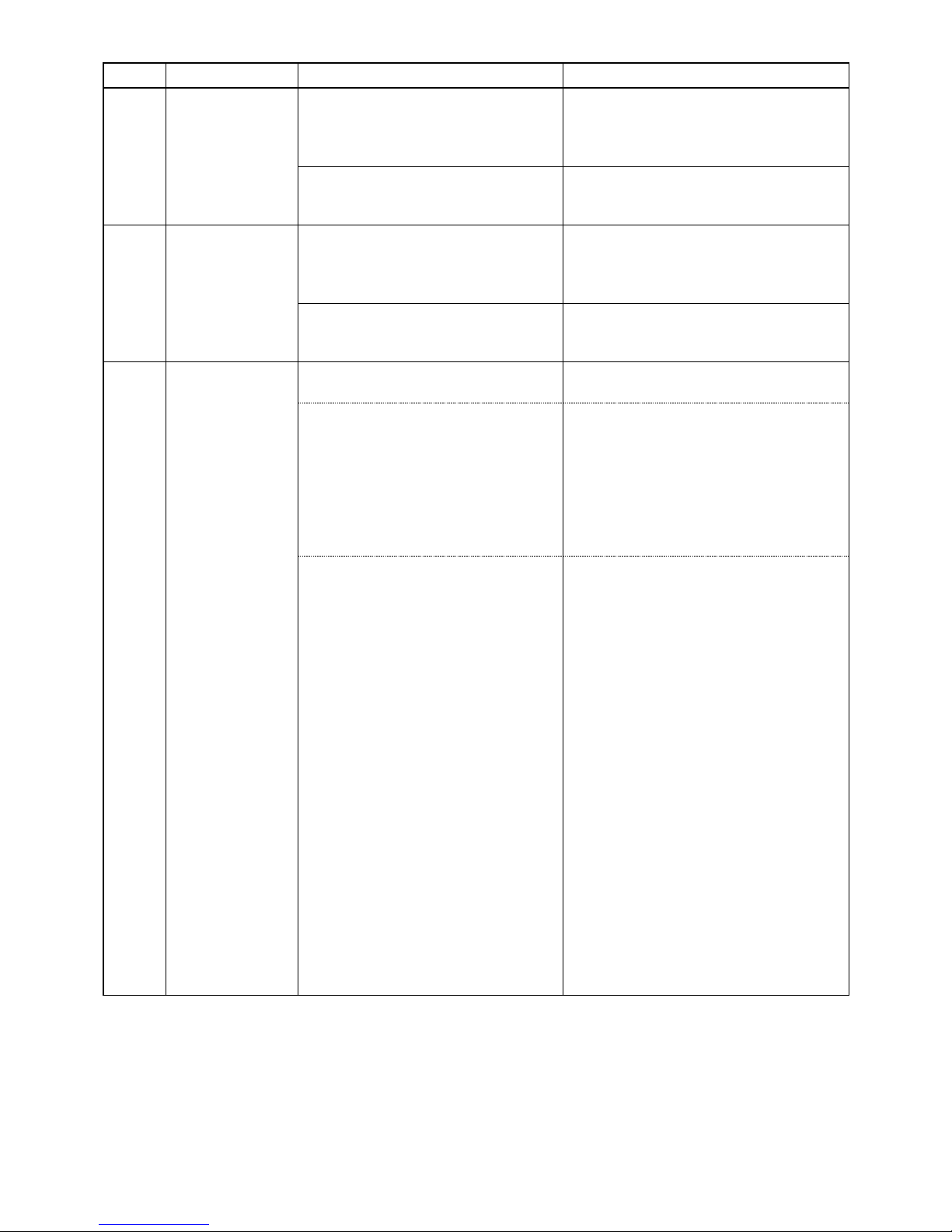
Maint. cover
Hinge
Lossnay core Filter
8. Overhauling procedures
Work precautions
• When touching the electric components such as circuit boards and fan motors, do not touch the components
for more than 5 minutes after power-off, and then start working.
•
Before replacing parts, follow the instructions described in the troubleshooting.
• When servicing, always keep proper footing.
• When servicing, make sure that the power supply isolator is off, so as no electrical shock or injury to occur.
Pay sufficient attention when working on the product.
• Always connect the power wires properly.
• After completing repairs, verify that the product operates properly.
• Always wear gloves when servicing.
The following pictures show GUF-100RDH4.
(1)
Turning power off
1 Shut down the unit.
2 Turn off the power supply isolator on the distribution board.
(2) Fan Section
1 Unscrew the cover fixing screw (one special (spl.)
screw 4 × 11, indicated by ).
2 Pull back the hinge. Open the maintenance (maint.)
cover and lift it off the fix piece.
3 Remove the Lossnay cores from the unit.
─ 19 ─
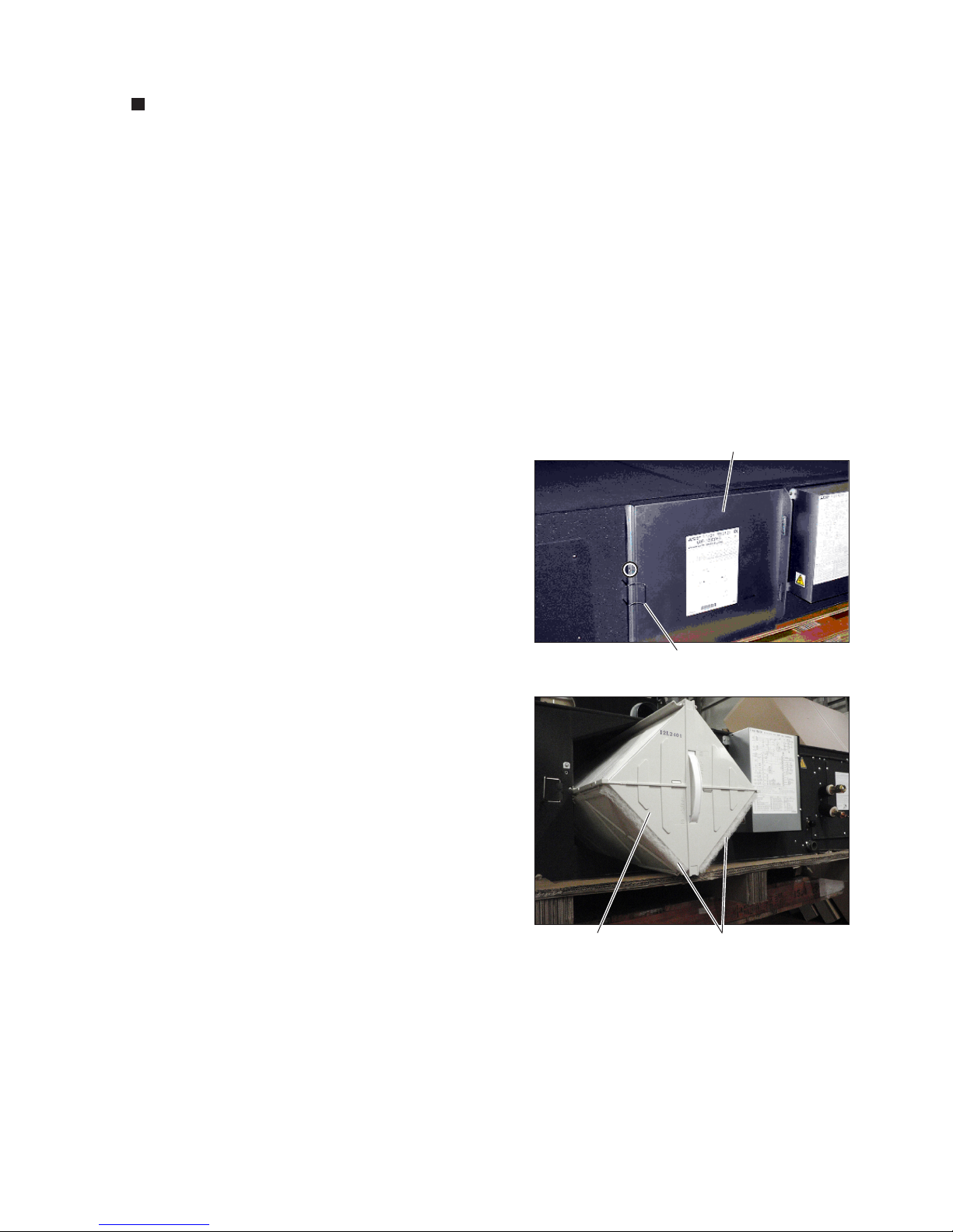
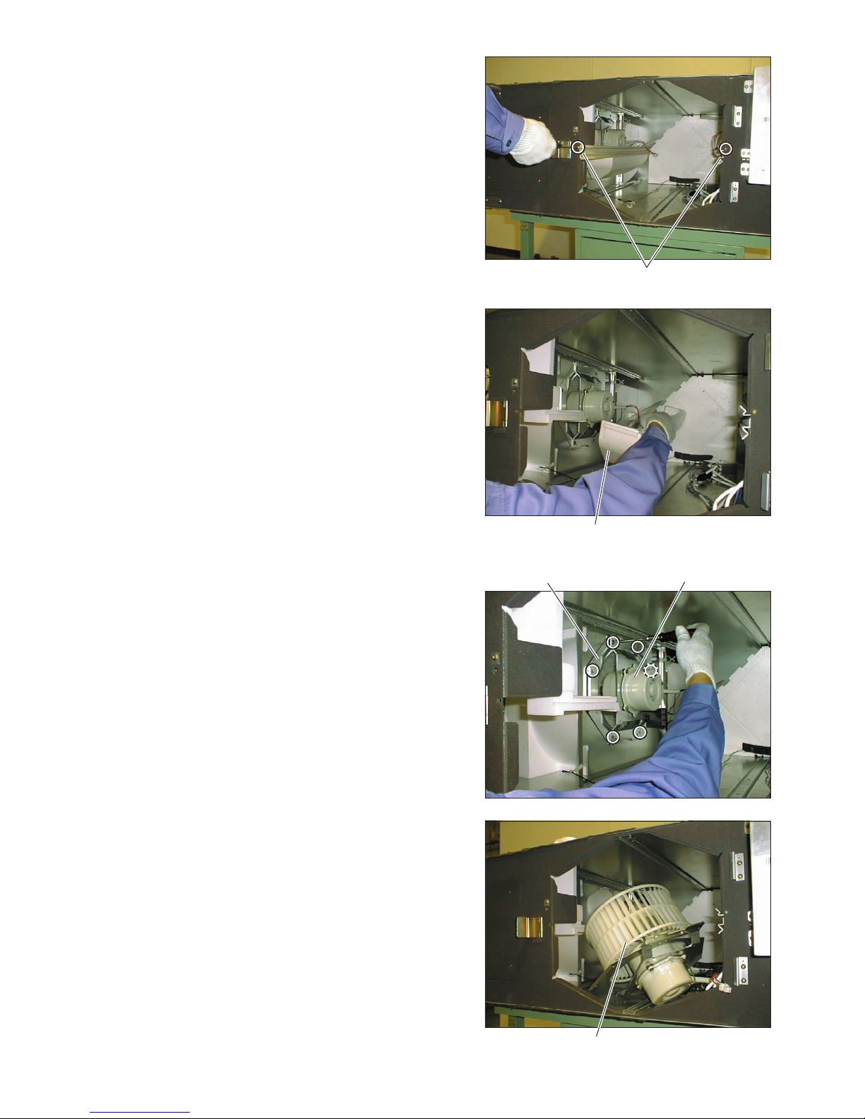
Motor fix plate
Fan assembly
Separator
5 Remove the separators from the fan parts.
6 Disconnect the connectors for the motor lead wire.
7 Unscrew the screws* (indicated by ) from the mo-
tor fix plate.
*GUF-50 types: four PTT screws 5 × 10
GUF-100 types: six PTT screws 5 × 10
8 Remove the fan assembly.
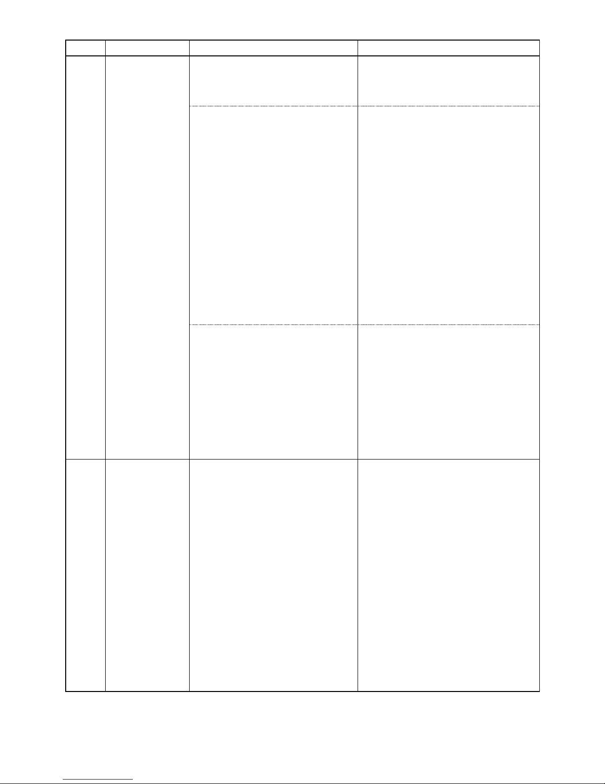
Motor
4 Unscrew the screws from the core guides (two PTT
screws 4 × 12, indicated by ), and remove the core
guides.
Core guide
 Loading...