

Mitsubishi GT10 User Manual


SAFETY PRECAUTIONS
(Always read these precautions before using this equipment.)
Before using this product, please read this manual and the relevant manuals introduced in this manual
carefully and pay full attention to safety to handle the product correctly.
The precautions given in this manual are concerned with this product.
In this manual, the safety precautions are ranked as "WARNING" and "CAUTION".
Indicates that incorrect handling may cause hazardous
WARNING
CAUTION
Note that the caution level may lead to a serious accident according to the circumstances. Always follow
the instructions of both levels because they are important to personal safety.
Please save this manual to make it accessible when required and always forward it to the end user.
conditions, resulting in death or severe injury.
Indicates that incorrect handling may cause hazardous
conditions, resulting in medium or slight personal injury or
physical damage.
[DESIGN PRECAUTIONS]
WARNING
Some failures of the GOT or cable may keep the outputs on or off.
Some failures of a touch panel may cause malfunction of the input objects such as a touch switch.
An external monitoring circuit should be provided to check for output signals which may lead to a
serious accident.
Not doing so can cause an accident due to false output or malfunction.
If a communication fault (including cable disconnection) occurs during monitoring on the GOT,
communication between the GOT and PLC CPU is suspended and the GOT becomes inoperative.
A system where the GOT is used should be configured to perform any significant operation to the
system by using the switches of a device other than the GOT on the assumption that a GOT
communication fault will occur.
Not doing so can cause an accident due to false output or malfunction.
Do not use the GOT as the warning device that may cause a serious accident.
An independent and redundant hardware or mechanical interlock is required to configure the device
that displays and outputs serious warning.
Failure to observe this instruction may result in an accident due to incorrect output or malfunction.
A - 1
[DESIGN PRECAUTIONS]
WARNING
Incorrect operation of the touch switch(s) may lead to a serious accident if the GOT backlight is gone
out.
When the GOT backlight goes out, the display section dims, while the input of the touch switch(s)
remains active.
This may confuse an operator in thinking that the GOT is in "screensaver" mode, who then tries to
release the GOT from this mode by touching the display section, which may cause a touch switch to
operate.
Note that the following occurs on the GOT when the backlight goes out.
<When using the GT105 >
The POWER LED blinks (green/orange) and the monitor screen appears blank.
<When using the GT104 >
The monitor screen appears blank.
<When using the GT103 or GT102 >
The monitor screen appears dimmed.
CAUTION
Do not bundle the control and communication cables with main-circuit, power or other wiring.
Run the above cables separately from such wiring and keep them a minimum of 100mm (3.94in.)
apart. Not doing so noise can cause a malfunction.
Do not press the GOT display section with a pointed material as a pen or driver.
Doing so can result in a damage or failure of the display section.
Before connecting to GOT, turn ON the controller to enable the communication.
When the communication of controller is not available, a communication error may occur in GOT.
[MOUNTING PRECAUTIONS]
WARNING
Be sure to shut off all phases of the external power supply used by the system before mounting or
removing the GOT to/from the panel.
Not doing so can cause the unit to fail or malfunction.
When installing the battery or memory board wear an earth band etc. to avoid the static electricity.
The static electricity can cause the unit to fail or malfunction.
Be sure to shut off all phases of the external power supply used by the system before mounting or
removing the memory board on to/ from the GOT.
Not doing so can cause the unit to fail or malfunction.
A - 2
CAUTION
Use the GOT in the environment that satisfies the general specifications described in this manual.
Not doing so can cause an electric shock, fire, malfunction or product damage or deterioration.
When mounting the GOT to the control panel, tighten the mounting screws in the specified torque
range.
Undertightening can cause the GOT to drop, short circuit or malfunction, and deteriorate the
waterproof effect and oilproof effect.
Overtightening can cause a drop, short circuit or malfunction due to the damage of the screws or the
GOT, and deteriorate the waterproof effect and oilproof effect due to distortion of the protective cover
for oil, GOT or panel.
Securely connect the memory board to the connector provided for the board.
When using the GOT in the environment of oil or chemicals, use the protective cover for oil.
Failure to do so may cause failure or malfunction due to the oil or chemical entering into the GOT.
[WIRING PRECAUTIONS]
WARNING
Be sure to shut off all phases of the external power supply used by the system before wiring.
Failure to do so may result in an electric shock, product damage or malfunctions.
Please make sure to ground FG terminal of the GOT power supply section by applying 100 or less
which is used exclusively for the GOT.
Not doing so may cause an electric shock or malfunction.
Correctly wire the GOT power supply section after confirming the rated voltage and terminal
arrangement of the product.
Not doing so can cause a fire or failure.
Tighten the terminal screws of the GOT power supply section in the specified torque range.
Undertightening can cause a short circuit or malfunction.
Overtightening can cause a short circuit or malfunction due to the damage of the screws or the GOT.
Exercise care to avoid foreign matter such as chips and wire offcuts entering the GOT.
Not doing so can cause a fire, failure or malfunction.
CAUTION
Plug the communication cable into the connector of the connected unit and tighten the mounting and
terminal screws in the specified torque range.
Undertightening can cause a short circuit or malfunction.
Overtightening can cause a short circuit or malfunction due to the damage of the screws or unit.
A - 3
[TEST OPERATION PRECAUTIONS]
WARNING
Before performing the test operations of the user creation monitor screen (such as turning ON or
OFF bit device, changing the word device current value, changing the settings or current values of
the timer or counter), read through the manual carefully and make yourself familiar with the operation
method.
During test operation, never change the data of the devices which are used to perform significant
operation for the system.
False output or malfunction can cause an accident.
[STARTUP/MAINTENANCE PRECAUTIONS]
WARNING
When power is on, do not touch the terminals.
Doing so can cause an electric shock or malfunction.
Connect the battery correctly.
Do not discharge, disassemble, heat, short, solder or throw the battery into the fire.
Incorrect handling may cause the battery to generate heat, burst or take fire, resulting in injuries or
fires.
Before starting cleaning or terminal screw retightening, always switch off the power externally in all
phases.
Not switching the power off in all phases can cause a unit failure or malfunction.
Undertightening can cause a short circuit or malfunction.
Overtightening can cause a short circuit or malfunction due to the damage of the screws or unit.
A - 4
CAUTION
Do not disassemble or modify the unit.
Doing so can cause a failure, malfunction, injury or fire.
Do not touch the conductive and electronic parts of the unit directly.
Doing so can cause a unit malfunction or failure.
The cables connected to the unit must be run in ducts or clamped.
Not doing so can cause the unit or cable to be damaged due to the dangling, motion or accidental
pulling of the cables or can cause a malfunction due to a cable connection fault.
When unplugging the cable connected to the unit, do not hold and pull the cable portion.
Doing so can cause the unit or cable to be damaged or can cause a malfunction due to a cable
connection fault.
Do not drop or apply any impact to the battery.
If any impact has been applied, discard the battery and never use it.
The battery may be damaged by the drop or impact.
Before touching the unit, always touch grounded metal, etc. to discharge static electricity from
human body, etc.
Not doing so can cause the unit to fail or malfunction.
Replace battery with GT11-50BAT by Mitsubishi electric Co. only.
Use of another battery may present a risk of fire or explosion.
Dispose of used battery promptly.
Keep away from children. Do not disassemble and do not dispose of in fire.
[DISPOSAL PRECAUTIONS]
CAUTION
When disposing of the product, handle it as industrial waste.
When disposing of batteries, separate them from other wastes according to the local regulations.
(For details of the battery directive in EU member states, refer to 18.4
.)
[TOUCH PANEL PRECAUTIONS]
CAUTION
For the analog-resistive film type touch panels, normally the adjustment is not required. However,
the difference between a touched position and the object position may occur as the period of use
elapses. When any difference between a touched position and the object position occurs, execute
the touch panel calibration.
When any difference between a touched position and the object position occurs, other object may be
activated. This may cause an unexpected operation due to incorrect output or malfunction.
A - 5

[TRANSPORTATION PRECAUTIONS]
CAUTION
When transporting lithium batteries, make sure to treat them based on the transport regulations.
(Refer to Appendix 3 for details of the regulated units.)
Before transporting the GOT, turn the GOT power on and check that the battery voltage status is
normal on the Time setting & display screen (utilities screen). In addition, confirm that the adequate
battery life remains on the rating plate.
Transporting the GOT with the low battery voltage or the battery the reached battery life may
unstabilize the backup data unstable during transportation.
Make sure to transport the GOT main unit and/or relevant unit(s) in the manner they will not be
exposed to the impact exceeding the impact resistance described in the general specifications of this
manual, as they are precision devices.
Failure to do so may cause the unit to fail.
Check if the unit operates correctly after transportation.
A - 6
REVISIONS
The manual number is given on the bottom left of the back cover.
Print Date Manual Number Ver. Revision
Nov., 2006 JY997D24701 A First edition
Jun, 2007 JY997D24701 B
Dec, 2007 JY997D24701 C
Feb., 2008 JY997D24701 D
Partial correcting
SAFETY PRECAUTIONS, ABBREVIATIONS AND GENERIC TERMS IN
THIS MANUAL, HOW TO READ THIS MANUAL, Section 1.1, 2.2, 3.2, 3.3,
Chapter 4, Section 6.2, 6.3, 7.1, 8.1, 8.2, Chapter 9, Section 11.1, Chapter
12, 13, Section 14.1, Chapter 15, Section 16.2, App - 1, App - 2, App - 4
Additions
Section 8.3, 16.4, App - 3
Partial correcting
SAFETY PRECAUTIONS, ABBREVIATIONS AND GENERIC TERMS IN
THIS MANUAL, HOW TO READ THIS MANUAL, Section 3.2, 9.1, 11.2.3,
Chapter 12, App-4
Partial correcting
ABBREVIATIONS AND GENERIC TERMS IN THIS MANUAL, HOW TO
READ THIS MANUAL, Chapter 2, Section 8.2, Chapter 11, Section 15.2,
App-1, App-4, Index-1
Oct., 2008 JY997D24701 E
Dec., 2008 JY997D24701 F
Jan., 2009 JY997D24701 G
Additions
Section 8.4
Partial correcting
ABBREVIATIONS AND GENERIC TERMS IN THIS MANUAL, HOW TO
READ THIS MANUAL, Chapter 1, Chapter 2, Chapter 3, Chapter 4,
Chapter 5, Chapter 6, Chapter 7, Chapter 8, Chapter 9, Chapter 11,
Chapter 12, Chapter 13, Chapter 14, Chapter 17, Chapter 18, App-1,
App-2, Index
Additions
Chapter 15, 16
Partial correcting
ABBREVIATIONS AND GENERIC TERMS IN THIS MANUAL, HOW TO
READ THIS MANUAL, Section1.1, Chapter 2, Chapter 3, Chapter 4,
Chapter 5, Chapter 6, Chapter 7, Chapter 8, Chapter 9, Chapter 11,
Chapter 12, Chapter 13, Chapter 14, Chapter 15, Chapter 17, Chapter 18,
App-1, App-2, App-4
Additions
Section11.1.4, Section11.1.5, Section14.3
Partial correcting
Section 7.1.2
A - 7
Print Date Manual Number Ver. Revision
Mar., 2009 JY997D24701 H
Aug., 2009 JY997D24701 J
Oct., 2009 JY997D24701 K
Partial correcting
SAFETY PRECAUTIONS, ABBREVIATIONS AND GENERIC TERMS,
HOW TO READ THIS MANUAL, Chapter 2, Section 3.1, 3.2, Section 4.2,
Section 8.3, Section 9.1, Section 12.1, Section 18.4, App-1, App-2, App-4,
Index
Additions
Section 8.8, Section 8.9
Partial correcting
ABBREVIATIONS AND GENERIC TERMS, HOW TO READ THIS
MANUAL, Section 2.2, Chapter 3, Chapter 4, Chapter 5, Section 7.1,
Section 8.8, Section 11.1, App-4
Partial correcting
ABBREVIATIONS AND GENERIC TERMS, ABOUT MANUALS, HOW TO
READ THIS MANUAL, Chapter 1, Section 2.2, Chapter 3, Chapter 8,
Chapter 9, Chapter 11, Chapter 12, Chapter 15, Chapter 17, Chapter 18,
App-2
Additions
Apr., 2010 JY997D24701 L
Jun., 2010 JY997D24701 M
Oct., 2010 JY997D24701 N
Jan., 2011 JY997D24701 P
Section 11.1.6, Section11.1.7, Section 15.3
Partial correcting
SAFETY PRECAUTIONS, ABBREVIATIONS AND GENERIC TERMS,
Chapter 2, Chapter 3, Chapter 4, Chapter 5, Chapter 8, Chapter 11,
Chapter 15, Section 17.3, Index
Partial correcting
ABBREVIATIONS AND GENERIC TERMS, HOW TO READ THIS
MANUAL, Section 7.1, Section 8.2, Section 8.3, Section 8.4,
Section 11.1.8, Section 17.2, App-4
Partial correcting
ABBREVIATIONS AND GENERIC TERMS, HOW TO READ THIS
MANUAL, Chapter 2, Chapter 3, Section 4.2, Section 5.1, Section 7.1,
Chapter 8, Chapter 10, Section 11.1, App-1, Index
Additions
Section 8.10
Partial correcting
ABBREVIATIONS AND GENERIC TERMS, HOW TO READ THIS
MANUAL, Section 4.2, Section 6.5, Section 9.2, Section 11.2, Section 12.2
A - 8
Print Date Manual Number Ver. Revision
Apr., 2011 JY997D24701 Q
Partial correcting
SAFETY PRECAUTIONS, ABBREVIATIONS AND GENERIC TERMS,
HOW TO READ THIS MANUAL, Section 2.2, Section 3.2, Section 6.2,
Section 6.5, Section 8.7, Chapter 13, Section 15.2
Jul., 2011 JY997D24701 R
Partial correcting
SAFETY PRECAUTIONS, ABBREVIATIONS AND GENERIC TERMS,
HOW TO READ THIS MANUAL, Section 3.2, Chapter 6, Chapter 8
Jan., 2012 JY997D24701 S
Partial correcting
ABBREVIATIONS AND GENERIC TERMS, HOW TO READ THIS
MANUAL, Section 2.2, Section 3.2
Jun., 2012 JY997D24701 T
Partial correcting
ABBREVIATIONS AND GENERIC TERMS, HOW TO READ THIS
MANUAL, Section 2.1, Section 2.2, Section 3.1
Sep., 2012 JY997D24701 U
Partial correcting
SAFETY PRECAUTIONS, Section 2.2.2, App-4
Additions
Feb., 2013 JY997D24701
Apr., 2013 JY997D24701 W
Jun., 2013 JY997D24701 X
Section 15.2.1, 15.2.7
V
Partial correcting
SAFETY PRECAUTIONS, Section 9.1, Section 15.1
Additions
Section 15.4
Partial correcting
Section 5.1
Partial correcting
Section 15.3.15
This manual confers no industrial property rights or any rights of any other kind, nor does it confer any patent licenses.
Mitsubishi Electric Corporation cannot be held responsible for any problems involving industrial property rights which may
occur as a result of using the contents noted in this manual.
© 2006 MITSUBISHI ELECTRIC CORPORATIONs
A - 9

INTRODUCTION
Thank you for choosing the Mitsubishi Graphic Operation Terminal.
Before using the equipment, please read this manual carefully to use the equipment to its optimum.
OUTLINE PRECAUTIONS
• This manual provides information for the use of the graphic operation terminal. The manual has been written
to be used by trained and competent personnel. The definition of such a person or persons is as follows;
1) Any engineer who is responsible for the planning, design and construction of automatic equipment using
the product associated with this manual should be of a competent nature, trained and qualified to the local
and national standards required to fulfill that role. These engineers should be fully aware of all aspects of
safety with regards to automated equipment.
2) Any commissioning or service engineer must be of a competent nature, trained and qualified to the local
and national standards required to fulfill that job. These engineers should also be trained in the use and
maintenance of the completed product. This includes being completely familiar with all associated
documentation for the said product. All maintenance should be carried out in accordance with established
safety practices.
3) All operators of the completed equipment should be trained to use that product in a safe and coordinated
manner in compliance to established safety practices. The operators should also be familiar with
documentation which is connected with the actual operation of the completed equipment.
Note: the term 'completed equipment' refers to a third party constructed device which contains or uses the
product associated with this manual.
• This product has been manufactured as a general-purpose part for general industries, and has not been
designed or manufactured to be incorporated in a device or system used in purposes related to human life.
• Before using the product for special purposes such as nuclear power, electric power, aerospace, medicine or
passenger movement vehicles, consult with Mitsubishi Electric.
• This product has been manufactured under strict quality control. However when installing the product where
major accidents or losses could occur if the product fails, install appropriate backup or failsafe functions in the
system.
• When using this product combining other products, please confirm the standard and the code, or regulation
which a user should suit. Moreover, please confirm the compatibility of this product to the system, machine,
and apparatus with which a user is used for user itself.
• If in doubt at any stage of the installation of the product always consult a professional electrical engineer who
is qualified and trained to the local and national standards. If in doubt about the operation or use, please
consult the nearest Mitsubishi Electric distributor.
• Since the example indicated by this manual, technical bulletin, the catalog, etc. is reference, please use it
after confirming the function and safety of equipment and system when employing. Mitsubishi Electric will
accept no responsibility for actual use of the product based on these illustrative examples.
• About this manual content, specification etc. may be changed without a notice for improvement.
• The information in this manual has been carefully checked and is believed to be accurate; however, you have
noticed a doubtful point, a doubtful error, etc., please contact the nearest Mitsubishi Electric distributor.
A - 10

CONTENTS
SAFETY PRECAUTIONS ...............................................................................................A-1
REVISIONS.....................................................................................................................A-7
INTRODUCTION...........................................................................................................A-10
OUTLINE PRECAUTIONS............................................................................................A-10
CONTENTS ..................................................................................................................A-11
ABOUT MANUALS .......................................................................................................A-17
ABBREVIATIONS AND GENERIC TERMS..................................................................A-18
HOW TO READ THIS MANUAL ...................................................................................A-23
1. OVERVIEW.......................................................... 1-1 to 1-5
1.1 Features .....................................................................................................................1-4
1.2 Rough Pre-operation Procedure ................................................................................1-5
2. SYSTEM CONFIGURATION ............................. 2-1 to 2-11
2.1 Overall Configuration .................................................................................................2-1
2.2 Component List .......................................................................................................... 2-3
2.2.1 GOT (GT10).................................................................................................................................... 2-5
2.2.2 Option (Optional components for GT10)......................................................................................... 2-6
3. SPECIFICATIONS ............................................. 3-1 to 3-14
3.1 General Specifications ...............................................................................................3-1
3.2 Performance Specifications .......................................................................................3-2
3.3 Power Supply Specifications.................................................................................... 3-14
4. PART NAME...................................................... 4-1 to 4-12
4.1 Front Panel.................................................................................................................4-1
4.1.1 GT1020, GT1030 ............................................................................................................................ 4-1
4.1.2 GT104[ ] ......................................................................................................................................... 4-1
4.1.3 GT105[ ] ......................................................................................................................................... 4-2
4.2 Back Panel ................................................................................................................. 4-3
4.2.1 GT1020-L[ ]D/L[ ]DW .................................................................................................................... 4-3
4.2.2 GT1020-L[ ]D2/L[ ]DW2 ................................................................................................................ 4-5
4.2.3 GT1020-L[ ]L/L[ ]LW ..................................................................................................................... 4-6
4.2.4 GT1030-L[ ]D/L[ ]DW/H[ ]D/H[ ]DW ............................................................................................ 4-7
4.2.5 GT1030-L[ ]D2/L[ ]DW2/H[ ]D2/H[ ]DW2 ....................................................................................4-9
4.2.6 GT1030-L[ ]L/L[ ]LW/H[ ]L/H[ ]LW............................................................................................. 4-10
4.2.7 GT1045-QSBD/GT1040-QBBD .................................................................................................... 4-11
4.2.8 GT1055-QSBD/GT1050-QBBD .................................................................................................... 4-12
5.
UL, cUL STANDARDS AND EMC DIRECTIVE
... 5-1 to 5-3
5.1 UL, cUL Standards..................................................................................................... 5-1
5.2 EMC DIRECTIVE ....................................................................................................... 5-1
5.2.1 Requirements for Conformance to EMC Directive..........................................................................5-1
A - 11

6. INSTALLATION..................................................6-1 to 6-11
6.1 Control Panel Inside Dimensions for Mounting GOT..................................................6-2
6.1.1 GT1020 ........................................................................................................................................... 6-2
6.1.2 GT1030 ........................................................................................................................................... 6-3
6.1.3 GT104[ ] .........................................................................................................................................6-4
6.1.4 GT105[ ] .........................................................................................................................................6-5
6.2 Panel Cutting Dimensions ..........................................................................................6-6
6.2.1 Panel cutting dimensions ................................................................................................................6-6
6.3 Mounting Position.......................................................................................................6-7
6.3.1 Mounting position............................................................................................................................ 6-7
6.4 Control Panel Temperature and Mounting Angle .......................................................6-9
6.4.1 Control panel temperature and mounting angle..............................................................................6-9
6.5 Installation Procedure...............................................................................................6-10
6.5.1 Installation procedure....................................................................................................................6-10
7. WIRING.................................................................7-1 to 7-9
7.1 Power Supply Wiring ..................................................................................................7-2
7.1.1 Cable types and wire end processing (GT1020, GT1030, GT104[ ]).............................................7-2
7.1.2 Cable types and wire end processing (GT105[ ])...........................................................................7-3
7.1.3 Wiring example (GT1020, GT1030)................................................................................................ 7-3
7.1.4 Wiring example (GT104[ ]) ............................................................................................................. 7-4
7.1.5 Wiring example (GT105[ ]) ............................................................................................................. 7-4
7.1.6 GOT’s ground ................................................................................................................................. 7-5
7.1.7 The cause of malfunctions related wiring/Remedy .........................................................................7-6
7.2 Wiring inside and outside the panel............................................................................7-8
7.2.1 Wiring inside ................................................................................................................................... 7-8
7.2.2 Outside the panel............................................................................................................................ 7-8
7.2.3 Attaching surge killers to control equipment ...................................................................................7-9
8. OPTION ..............................................................8-1 to 8-34
8.1 Protective Sheet .........................................................................................................8-1
8.1.1 Applicable protective sheet .............................................................................................................8-1
8.1.2 Installing procedure.........................................................................................................................8-2
8.2 RS-232/USB conversion adaptor ...............................................................................8-3
8.2.1 Shape, dimensions, and names of adaptor components ................................................................ 8-3
8.2.2 Installing procedure.........................................................................................................................8-4
8.2.3 Driver installation ............................................................................................................................ 8-5
8.2.4 Method for uninstalling driver........................................................................................................ 8-16
8.3 Battery ......................................................................................................................8-17
8.3.1 Applicable battery ......................................................................................................................... 8-17
8.3.2 Battery specifications ....................................................................................................................8-17
8.3.3 Battery replacement procedure.....................................................................................................8-18
8.4 Memory loader..........................................................................................................8-20
8.4.1 Part name ..................................................................................................................................... 8-21
8.4.2 Function specification ................................................................................................................... 8-22
8.5 Memory board ..........................................................................................................8-24
8.5.1 Applicable memory board .............................................................................................................8-24
8.5.2 Installing and removing procedures of the memory board ............................................................8-24
A - 12

8.6 Stand........................................................................................................................8-26
8.6.1 Applicable stand............................................................................................................................ 8-26
8.6.2 Installing procedure....................................................................................................................... 8-26
8.7 Protective cover for oil.............................................................................................. 8-27
8.7.1 Applicable protective cover for oil ................................................................................................. 8-27
8.7.2 Installing procedure....................................................................................................................... 8-27
8.8 Serial Multi-Drop Connection Unit............................................................................ 8-29
8.8.1 Serial multi-drop connection unit................................................................................................... 8-29
8.8.2 Applicable serial multi-drop connection unit.................................................................................. 8-30
8.8.3 Part name ..................................................................................................................................... 8-30
8.8.4 Installation..................................................................................................................................... 8-31
8.8.5 Caution for compliance with EMC Directive.................................................................................. 8-31
8.9 Connector Conversion Adapter................................................................................ 8-32
8.9.1 Applicable connector conversion adapter .....................................................................................8-32
8.9.2 Installing procedure....................................................................................................................... 8-32
8.10 Panel-Mounted USB Port Extension ...................................................................... 8-33
8.10.1 Applicable panel-mounted USB port extension .......................................................................... 8-33
8.10.2 Part name ................................................................................................................................... 8-33
8.10.3 Installing procedure..................................................................................................................... 8-33
9. UTILITY FUNCTION ............................................ 9-1 to 9-7
9.1 Utility Function List ..................................................................................................... 9-1
9.2 Utility Display..............................................................................................................9-3
9.2.1 Display operation of main menu ..................................................................................................... 9-3
9.2.2 Utility basic configuration ................................................................................................................ 9-6
10. LANGUAGE SETTING (Language).............. 10-1 to 10-2
10.1 Display language setting ........................................................................................ 10-1
10.1.1 Display language setting function ............................................................................................... 10-1
10.1.2 Language display operation........................................................................................................ 10-1
10.1.3 Language setting operation ........................................................................................................ 10-1
11. COMMUNICATION INTERFACE SETTING
(COMMUNICATION SETTING)................... 11-1 to 11-24
11.1 Standard I/F Setting ...............................................................................................11-1
11.1.1 Standard I/F functions.................................................................................................................11-1
11.1.2 Standard I/F display operation .................................................................................................... 11-1
11.1.3 Display contents of standard I/F ................................................................................................. 11-2
11.1.4 Detail information setting operation ............................................................................................ 11-6
11.1.5 Channel setting operation ........................................................................................................... 11-9
11.1.6 Driver setting operation............................................................................................................. 11-10
11.1.7 AT command operation.............................................................................................................11-11
11.1.8 Installing of communication driver............................................................................................. 11-12
11.2 Data Transfer .......................................................................................................11-13
11.2.1 Data transfer functions.............................................................................................................. 11-13
11.2.2 Data transfer operation ............................................................................................................. 11-13
11.2.3 Data transfer display ................................................................................................................. 11-14
11.3 Communication Monitor .......................................................................................11-15
11.3.1 Communication Monitor functions............................................................................................. 11-15
11.3.2 Communication Monitor display operation................................................................................ 11-15
11.3.3 Screen display content..............................................................................................................11-16
A - 13

11.4 Keyword................................................................................................................11-18
11.4.1 Keyword functions..................................................................................................................... 11-18
11.4.2 Keyword display operation........................................................................................................11-18
11.4.3 Regist........................................................................................................................................ 11-19
11.4.4 Delete........................................................................................................................................ 11-22
11.4.5 Clear .........................................................................................................................................11-23
11.4.6 Protect....................................................................................................................................... 11-24
12. DISPLAY AND OPERATION SETTINGS
(GOT SET UP)..............................................12-1 to 12-16
12.1 Display Settings......................................................................................................12-2
12.1.1 Display setting functions ............................................................................................................. 12-2
12.1.2 Display operation of display setting ............................................................................................12-3
12.1.3 Display setting operations...........................................................................................................12-4
12.2 Operation Settings..................................................................................................12-8
12.2.1 Operation setting functions ......................................................................................................... 12-8
12.2.2 Display operation of operation setting.........................................................................................12-9
12.2.3 Setting operation of operation................................................................................................... 12-10
13. CLOCK SETTINGS AND BATTERY STATUS DISPLAY
(TIME SETTING AND DISPLAY)...................13-1 to 13-2
13.1 Time Setting and Display........................................................................................13-1
13.1.1 Time setting and display functions.............................................................................................. 13-1
13.1.2 Clock display and setting operation ............................................................................................13-1
13.1.3 Clock setting operations..............................................................................................................13-2
14. FILE DISPLAY (DATA) ................................14-1 to 14-10
14.1 Data Storage Location............................................................................................14-1
14.2 OS Information .......................................................................................................14-2
14.2.1 Function of OS information ......................................................................................................... 14-2
14.2.2 Display operation of OS information screen ...............................................................................14-2
14.2.3 OS information operation ............................................................................................................14-3
14.3 Font Data................................................................................................................14-4
14.3.1 Function of font data ...................................................................................................................14-4
14.3.2 Display operation of font data screen .........................................................................................14-4
14.3.3 Font data operation.....................................................................................................................14-5
14.4 Clear data...............................................................................................................14-6
14.4.1 Clear data functions ....................................................................................................................14-6
14.4.2 Clear data display .......................................................................................................................14-6
14.4.3 Clear data operation ................................................................................................................... 14-6
14.5 GT10-50FMB..........................................................................................................14-7
14.5.1 GT10-50FMB functions (For GT104[ ], GT105[ ] only) ............................................................. 14-7
14.5.2 GT10-50FMB display operation .................................................................................................. 14-7
14.5.3 GT10-50FMB operation .............................................................................................................. 14-8
14.5.4 Error display.............................................................................................................................. 14-10
A - 14

15. GOT DEBUG ............................................... 15-1 to 15-48
15.1 Debug..................................................................................................................... 15-1
15.2 Device Monitor .......................................................................................................15-1
15.2.1 System configuration .................................................................................................................. 15-1
15.2.2 Devices that can be monitored ................................................................................................... 15-2
15.2.3 Precautions ................................................................................................................................. 15-2
15.2.4 Display operation of device monitor............................................................................................ 15-3
15.2.5 Information displayed on the device monitor screen and key functions...................................... 15-4
15.2.6 Basic operation of device monitor............................................................................................... 15-6
15.2.7 Device registration ...................................................................................................................... 15-7
15.2.8 Quick test .................................................................................................................................. 15-10
15.3 FX List Editor (For GT104[ ], GT105[ ] only) ......................................................15-13
15.3.1 Display operation of FX list editor ............................................................................................. 15-13
15.3.2 Specifications............................................................................................................................ 15-15
15.3.3 Access range ............................................................................................................................ 15-16
15.3.4 Precautions ............................................................................................................................... 15-17
15.3.5 Display ......................................................................................................................................15-18
15.3.6 Operation Procedures............................................................................................................... 15-20
15.3.7 Selection and operation of modes ............................................................................................ 15-22
15.3.8 Sequence program display .......................................................................................................15-23
15.3.9 Searching commands and devices ...........................................................................................15-25
15.3.10 Writing commands .................................................................................................................. 15-27
15.3.11 Changing operands, set values .............................................................................................. 15-30
15.3.12 Deleting commands ................................................................................................................ 15-31
15.3.13 Sequence program all clear .................................................................................................... 15-32
15.3.14 PLC diagnostics ...................................................................................................................... 15-33
15.3.15 Parameter setting....................................................................................................................15-35
15.3.16 Keywords ................................................................................................................................ 15-38
15.3.17 List monitor ............................................................................................................................. 15-40
15.3.18 Action for an incorrect key input.............................................................................................. 15-42
15.3.19 Error Messages and Corrective Actions ................................................................................. 15-42
15.4 FX3U-ENET-ADP Communication Setting Function............................................ 15-43
15.4.1 SPECIFICATIONS .................................................................................................................... 15-43
15.4.2 Display Operation of FX3U-ENET-ADP Communication Setting Function ............................... 15-45
15.4.3 Setting operation....................................................................................................................... 15-46
16. CLEANING OF DISPLAY SECTION (CLEAN) .......... 16-1
16.1 Clean...................................................................................................................... 16-1
16.1.1 Display operation of clean........................................................................................................... 16-1
17. OS INSTALLATION....................................... 17-1 to 17-4
17.1 About the OS.......................................................................................................... 17-1
17.2 Standard monitor OS/Communication Driver Installation....................................... 17-1
17.3 Standard Monitor OS/Communication Driver Installation Using Memory Board .... 17-3
17.3.1 Installation method when the GOT is turned on.......................................................................... 17-3
18. MAINTENANCE AND INSPECTION............. 18-1 to 18-6
18.1 Daily Inspection...................................................................................................... 18-2
18.2 Periodic Inspection................................................................................................. 18-2
18.3 Cleaning Method .................................................................................................... 18-3
18.4 Battery Voltage Low Detection and Battery Replacement .....................................18-4
A - 15

18.5 Backlight Shutoff Detection ....................................................................................18-6
18.5.1 Backlight shutoff detection and external alarm ...........................................................................18-6
APPENDICES ............................................App-1 to App-15
Appendix 1 External Dimensions ............................................................................. App- 1
Appendix 2 Usage Condition of Utility Function ..................................................... App- 12
Appendix 3 Transportation Precautions ................................................................. App- 14
Appendix 4 List of Functions Added by GT Designer2 Version Upgrade
(For GOT1000 Series) ........................................................................ App- 15
INDEX .........................................................................Index-1
A - 16

ABOUT MANUALS
The following manuals are also related to this product.
In necessary, order them by quoting the details in the tables below.
Related Manuals
Manual Name
GT Designer2 Version2 Basic Operation/Data Transfer Manual (For GOT1000 Series)
Describes methods of the GT Designer2 installation operation, basic operation for drawing and transmitting data
to GOT1000 series
(Sold separately)
GT Designer2 Version2 Screen Design Manual (For GOT1000 Series) 1/3
GT Designer2 Version2 Screen Design Manual (For GOT1000 Series) 2/3
GT Designer2 Version2 Screen Design Manual (For GOT1000 Series) 3/3
Describes specifications and settings of the object functions used in GT Designer2
(Sold separately)
GOT1000 Series Connection Manual (1/3, 2/3, 3/3)
Describes system configurations of the connection method applicable to GOT1000 series and cable creation
method
(Sold separately)
GT Designer3 Version1 Screen Design Manual (For GOT1000 Series) (Fundamentals)1/2, 2/2
Describes methods of the GT Designer3 installation operation, basic operation for drawing and transmitting data
to GOT1000 series
(Sold separately)
GT Designer3 Version1 Screen Design Manual (For GOT1000 Series) (Functions) 1/2
GT Designer3 Version1 Screen Design Manual (For GOT1000 Series) (Functions) 2/2
Describes methods of the GT Designer3 installation operation, basic operation for drawing and transmitting data
to GOT1000 series
(Sold separately)
GOT1000 Series Connection Manual (Mitsubishi Products) for GT Works3
Describes system configurations of the connection method applicable to GOT1000 series and cable creation
method
(Sold separately)
GOT1000 Series Connection Manual (Non-Mitsubishi Products 1) for GT Works3
Describes system configurations of the connection method applicable to GOT1000 series and cable creation
method
(Sold separately)
GOT1000 Series Connection Manual (Non-Mitsubishi Products 2) for GT Works3
Describes system configurations of the connection method applicable to GOT1000 series and cable creation
method
(Sold separately)
GOT1000 Series Connection Manual (Microcomputer, MODBUS Products, Peripherals) for GT Works3
Describes system configurations of the connection method applicable to GOT1000 series and cable creation
method
(Sold separately)
*1 The manual in PDF-format is included in the GT Works2, GT Designer2, GT Works3 and GT Designer3 products.
Manual Number
(Model Code)
SH-080529ENG
(1D7M24)
*1
SH-080530ENG
(1D7M25)
*1
SH-080532ENG
(1D7M26)
*1
SH-080866ENG
(1D7MB9)
*1
SH-080867ENG
(1D7MC1)
*1
SH-080868ENG
(1D7MC2)
*1
SH-080869ENG
(1D7MC3)
*1
SH-080870ENG
(1D7MC4)
*1
SH-080871ENG
(1D7MC5)
*1
A - 17
ABBREVIATIONS AND GENERIC TERMS
GOT
Abbreviations and generic terms Description
GT1695 GT1695M-X Abbreviation of GT1695M-XTBA, GT1695M-XTBD
GT1685 GT1685M-S Abbreviation of GT1685M-STBA, GT1685M-STBD
GT1675M-S Abbreviation of GT1675M-STBA, GT1675M-STBD
GT1675
GT1672 GT1672-VN Abbreviation of GT1672-VNBA, GT1672-VNBD
GT1665
GT1662 GT1662-VN Abbreviation of GT1662-VNBA, GT1662-VNBD
GT1655 GT1655-V Abbreviation of GT1655-VTBD
GT1 6
GT1595 GT1595-X Abbreviation of GT1595-XTBA, GT1595-XTBD
GT1585
GT157
GT156
GOT1000
Series
GT155
GT1 5
GT145
GT14 Abbreviation of GT1455-Q, GT1450-Q
GT1275 GT1275-V Abbreviation of GT1275-VNBA, GT1275-VNBD
GT1265 GT1265-V Abbreviation of GT1265-VNBA, GT1265-VNBD
GT12 Abbreviation of GT1275, GT1265
GT11 5
GT11
GT105
GT104
GT1030
GT1675M-V Abbreviation of GT1675M-VTBA, GT1675M-VTBD
GT1675-VN Abbreviation of GT1675-VNBA, GT1675-VNBD
GT1665M-S Abbreviation of GT1665M-STBA, GT1665M-STBD
GT1665M-V Abbreviation of GT1665M-VTBA, GT1665M-VTBD
Abbreviation of GT1695, GT1685, GT1675, GT1672, GT1665, GT1662, GT1655,
GT16 Handy GOT
GT1585V-S Abbreviation of GT1585V-STBA, GT1585V-STBD
GT1585-S Abbreviation of GT1585-STBA, GT1585-STBD
GT1575V-S Abbreviation of GT1575V-STBA, GT1575V-STBD
GT1575-S Abbreviation of GT1575-STBA, GT1575-STBD
GT1575-V Abbreviation of GT1575-VTBA, GT1575-VTBD
GT1575-VN Abbreviation of GT1575-VNBA, GT1575-VNBD
GT1572-VN Abbreviation of GT1572-VNBA, GT1572-VNBD
GT1565-V Abbreviation of GT1565-VTBA, GT1565-VTBD
GT1562-VN Abbreviation of GT1562-VNBA, GT1562-VNBD
GT1555-V Abbreviation of GT1555-VTBD
GT1555-Q Abbreviation of GT1555-QTBD, GT1555-QSBD
GT1550-Q Abbreviation of GT1550-QLBD
Abbreviation of GT1595, GT1585, GT157 , GT156 , GT155
GT1455-Q Abbreviation of GT1455-QTBDE, GT1455-QTBD
GT1450-Q Abbreviation of GT1450-QLBDE, GT1450-QLBD
GT11 55-Q
GT1150-Q Abbreviation of GT1150-QLBDQ, GT1150-QLBDA, GT1150-QLBD
GT1055-Q Abbreviation of GT1055-QSBD
GT1050-Q Abbreviation of GT1050-QBBD
GT1045-Q Abbreviation of GT1045-QSBD
GT1040-Q Abbreviation of GT1040-QBBD
Abbreviation of GT1155-QTBDQ, GT1155-QSBDQ, GT1155-QTBDA, GT1155-QSBDA,
GT1155-QTBD, GT1155-QSBD
Abbreviation of GT115 , GT11 Handy GOT,
Abbreviation of GT1030-LBD, GT1030-LBD2, GT1030-LBL, GT1030-LBDW,
GT1030-LBDW2, GT1030-LBLW, GT1030-LWD, GT1030-LWD2, GT1030-LWL,
GT1030-LWDW, GT1030-LWDW2, GT1030-LWLW, GT1030-HBD, GT1030-HBD2,
GT1030-HBL, GT1030-HBDW, GT1030-HBDW2, GT1030-HBLW, GT1030-HWD,
GT1030-HWD2, GT1030-HWL, GT1030-HWDW, GT1030-HWDW2, GT1030-HWLW
(Continued to next page)
A - 18
Abbreviations and generic terms Description
Abbreviation of GT1020-LBD, GT1020-LBD2, GT1020-LBL, GT1020-LBDW,
GT1 020
GT1 0
GOT1000
Series
GOT900 Series Abbreviation of GOT-A900 series, GOT-F900 series
GOT800 Series Abbreviation of GOT-800 series
Handy
GOT
GT SoftGOT1000 Abbreviation of GT SoftGOT1000
GT16
Handy
GOT
GT11
Handy
GOT
GT1665HS-V Abbreviation of GT1665HS-VTBD
GT1155HS-Q Abbreviation of GT1155HS-QSBD
GT1150HS-Q Abbreviation of GT1150HS-QLBD
GT1020-LBDW2, GT1020-LBLW, GT1020-LWD, GT1020LWD2, GT1020-LWL,
GT1020-LWDW, GT1020-LWDW2, GT1020-LWLW
Abbreviation of GT105 , GT104 , GT1030, GT1020
Communication unit
Abbreviations and generic terms Description
Bus connection unit
Serial communication unit GT15-RS2-9P, GT15-RS4-9S, GT15-RS4-TE
RS-422 conversion unit GT15-RS2T4-9P, GT15-RS2T4-25P
Ethernet communication unit GT15-J71E71-100
MELSECNET/H communication unit GT15-J71LP23-25, GT15-J71BR13
MELSECNET/10 communication unit
CC-Link IE Controller Network
communication unit
CC-Link IE Field Network communication unit GT15-J71GF13-T2
CC-Link communication unit
Interface converter unit GT15-75IF900
Serial multi-drop connection unit GT01-RS4-M
Connection Conversion Adapter GT10-9PT5S
RS-232/485 signal conversion adapter GT14-RS2T4-9P
GT15-QBUS, GT15-QBUS2, GT15-ABUS, GT15-ABUS2, GT15-75QBUSL, GT15-75QBUS2L,
GT15-75ABUSL, GT15-75ABUS2L
GT15-75J71LP23-Z
GT15-J71GP23-SX
GT15-J61BT13, GT15-75J61BT13-Z
*1
, GT15-75J71BR13-Z
*2
*3
*1 A9GT-QJ71LP23 + GT15-75IF900 set
*2 A9GT-QJ71BR13 + GT15-75IF900 set
*3 A8GT-J61BT13 + GT15-75IF900 set
Option unit
Abbreviations and generic terms Description
Printer unit GT15-PRN
Video input unit GT16M-V4, GT15V-75V4
Video/RGB unit
Multimedia unit GT16M-MMR
CF card unit GT15-CFCD
CF card extension unit
External I/O unit GT15-DIO, GT15-DIOR
Sound output unit GT15-SOUT
RGB input unit GT16M-R2, GT15V-75R1
Video/RGB input unit GT16M-V4R1, GT15V-75V4R1
RGB output unit GT16M-ROUT, GT15V-75ROUT
*1
GT15-CFEX-C08SET
*1 GT15-CFEX + GT15-CFEXIF + GT15-C08CF set.
A - 19
Option
Abbreviations and generic terms Description
GT05-MEM-16MC, GT05-MEM-32MC, GT05-MEM-64MC, GT05-MEM-128MC,
Memory card
Memory card adaptor GT05-MEM-ADPC
Option function board
Battery GT15-BAT, GT11-50BAT
Protective Sheet
Protective cover for oil
USB environmental protection cover GT16-UCOV, GT16-50UCOV, GT15-UCOV, GT14-50UCOV, GT11-50UCOV
Stand GT15-90STAND, GT15-80STAND, GT15-70STAND, A9GT-50STAND, GT05-50STAND
Attachment
Backlight
Multi-color display board GT15-XHNB, GT15-VHNB
Connector conversion box GT11H-CNB-37S, GT16H-CNB-42S
Emergency stop sw guard cover GT11H-50ESCOV, GT16H-60ESCOV
Memory loader GT10-LDR
Memory board GT10-50FMB
Panel-mounted USB port extension GT14-C10EXUSB-4S, GT10-C10EXUSB-5S
CF card
SD card L1MEM-2GBSD, L1MEM-4GBSD
GT05-MEM-256MC, GT05-MEM-512MC, GT05-MEM-1GC, GT05-MEM-2GC,
GT05-MEM-4GC, GT05-MEM-8GC, GT05-MEM-16GC
GT1 6 -MES B , GT15 - F NB, GT 1 5-QF N B, GT1 5 - QFN B 1 6M,
GT15-QFNB32M, GT15-QFNB48M, GT11-50FNB, GT15-MESB48M
GT16-90PSCB, GT16-90PSGB, GT16-90PSCW, GT16-90PSGW,
GT16-80PSCB, GT16-80PSGB, GT16-80PSCW, GT16-80PSGW,
GT16-70PSCB, GT16-70PSGB, GT16-70PSCW, GT16-70PSGW,
For GT16
For GT15
Fo r GT14 GT1 4 -50P S CB, GT 1 4 -50P S GB, GT 1 4-50 P S CW, GT1 4 - 50PS G W
Fo r GT12 GT11 - 7 0PSC B , GT11- 6 5 PSCB
For GT11
For GT10
GT05-90PCO, GT05-80PCO, GT05-70PCO, GT05-60PCO, GT05-50PCO,
GT16-50PCO, GT10-40PCO, GT10-30PCO, GT10-20PCO
GT15-70ATT-98, GT15-70ATT-87, GT15-60ATT-97, GT15-60ATT-96,
GT15-60ATT-87, GT15-60ATT-77, GT15-50ATT-95W, GT15-50ATT-85
GT16-90XLTT, GT16-80SLTT, GT16-70SLTT, GT16-70VLTT, GT16-70VLTTA, GT16-70VLTN,
GT16-60SLTT, GT16-60VLTT, GT16-60VLTN, GT15-90XLTT, GT15-80SLTT, GT15-70SLTT,
GT15-70VLTT, GT15-70VLTN, GT15-60VLTT, GT15-60VLTN
GT16-60PSCB, GT16-60PSGB, GT16-60PSCW, GT16-60PSGW,
GT16-50PSCB, GT16-50PSGB, GT16-50PSCW, GT16-50PSGW,
GT16-90PSCB-012, GT16-80PSCB-012, GT16-70PSCB-012,
GT16-60PSCB-012, GT16-50PSCB-012, GT16H-60PSC
GT15-90PSCB, GT15-90PSGB, GT15-90PSCW, GT15-90PSGW,
GT15-80PSCB, GT15-80PSGB, GT15-80PSCW, GT15-80PSGW,
GT15-70PSCB, GT15-70PSGB, GT15-70PSCW, GT15-70PSGW,
GT15-60PSCB, GT15-60PSGB, GT15-60PSCW, GT15-60PSGW,
GT15-50PSCB, GT15-50PSGB, GT15-50PSCW, GT15-50PSGW
GT11-50PSCB, GT11-50PSGB, GT11-50PSCW, GT11-50PSGW,
GT11H-50PSC
GT10-50PSCB, GT10-50PSGB, GT10-50PSCW, GT10-50PSGW,
GT10-40PSCB, GT10-40PSGB, GT10-40PSCW, GT10-40PSGW,
GT10-30PSCB, GT10-30PSGB, GT10-30PSCW, GT10-30PSGW,
GT10-20PSCB, GT10-20PSGB, GT10-20PSCW, GT10-20PSGW
A - 20
Software
Abbreviations and generic terms Description
GT Works3
GT Designer3 Abbreviation of screen drawing software GT Designer3 for GOT1000 series
GT Simulator3 Abbreviation of screen simulator GT Simulator3 for GOT1000/GOT900 series
GT SoftGOT1000 Abbreviation of monitoring software GT SoftGOT1000
GT Converter2 Abbreviation of data conversion software GT Converter2 for GOT1000/GOT900 series
GT Designer2 Classic Abbreviation of screen drawing software GT Designer2 Classic for GOT900 series
GT Designer2 Abbreviation of screen drawing software GT Designer2 for GOT1000/GOT900 series
iQ Works Abbreviation of iQ Platform compatible engineering environment MELSOFT iQ Works
MELSOFT Navigator
GX Works2
GX Simulator2 Abbreviation of GX Works2 with the simulation function
GX Simulator
GX Developer
GX LogViewer
PX Developer
MT Works2
MT Developer
MR Configurator2
MR Configurator
FR Configurator
NC Configurator Abbreviation of CNC parameter setting support tool NC Configurator
FX Configurator-FP
FX3U-ENET-L Configuration tool Abbreviation of FX3U-ENET-L type Ethernet module setting software (SW1D5-FXENETL-E)
RT ToolBox2 Abbreviation of robot program creation software (3D-11C-WINE)
MX Component
MX Sheet
QnUDVCPU & LCPU Logging
Configuration Tool
Abbreviation of the SW DNC-GTWK3-E and SW DNC-GTWK3-EA
Generic term for integrated development environment software included in the SW DNC-IQWK (iQ
Platform compatible engineering environment MELSOFT iQ Works)
Abbreviation of SW DNC-GXW2-E and SW DNC-GXW2-EA type programmable controller
engineering software
Abbreviation of SW D5C-LLT-E(-EV) type ladder logic test tool function software packages
(SW5D5C-LLT (-EV) or later versions)
Abbreviation of SW D5C-GPPW-E(-EV)/SW D5F-GPPW-E type software package
Abbreviation of SW DNN-VIEWER-E type software package
Abbreviation of SW D5C-FBDQ-E type FBD software package for process control
Abbreviation of motion controller engineering environment MELSOFT MT Works2
(SW DNC-MTW2-E)
Abbreviation of SW RNC-GSV type integrated start-up support software for motion controller Q series
Abbreviation of SW DNC-MRC2-E type Servo Configuration Software
Abbreviation of MRZJW -SETUP E type Servo Configuration Software
Abbreviation of Inverter Setup Software (FR-SW -SETUP-WE)
Abbreviation of parameter setting, monitoring, and testing software packages for FX3U-20SSC-H
(SW D5C-FXSSC-E)
Abbreviation of MX Component Version (SW D5C-ACT-E, SW D5C-ACT-EA)
Abbreviation of MX Sheet Version (SW D5C-SHEET-E, SW D5C-SHEET-EA)
Abbreviation of QnUDVCPU & LCPU Logging Configuration Tool (SW1DNN-LLUTL-E)
License key (for GT SoftGOT1000)
Abbreviations and generic terms Description
License GT15-SGTKEY-U, GT15-SGTKEY-P
A - 21

Others
Abbreviations and generic terms Description
IAI Abbreviation of IAI Corporation
AZBIL Abbreviation of Azbil Corporation (former Yamatake Corporation)
OMRON Abbreviation of OMRON Corporation
KEYENCE Abbreviation of KEYENCE CORPORATION
KOYO EI Abbreviation of KOYO ELECTRONICS INDUSTRIES CO., LTD.
SHARP Abbreviation of Sharp Manufacturing Systems Corporation
JTEKT Abbreviation of JTEKT Corporation
SHINKO Abbreviation of Shinko Technos Co., Ltd.
CHINO Abbreviation of CHINO CORPORATION
TOSHIBA Abbreviation of TOSHIBA CORPORATION
TOSHIBA MACHINE Abbreviation of TOSHIBA MACHINE CO., LTD.
HITACHI IES Abbreviation of Hitachi Industrial Equipment Systems Co., Ltd.
HITACHI Abbreviation of Hitachi, Ltd.
FUJI Abbreviation of FUJI ELECTRIC CO., LTD.
PANASONIC Abbreviation of Panasonic Corporation
PANASONIC INDUSTRIAL DEVICES SUNX Abbreviation of Panasonic Industrial Devices SUNX Co., Ltd.
YASKAWA Abbreviation of YASKAWA Electric Corporation
YOKOGAWA Abbreviation of Yokogawa Electric Corporation
ALLEN-BRADLEY Abbreviation of Allen-Bradley products manufactured by Rockwell Automation, Inc.
GE Abbreviation of GE Intelligent Platforms
LS IS Abbreviation of LS Industrial Systems Co., Ltd.
SCHNEIDER Abbreviation of Schneider Electric SA
SICK Abbreviation of SICK AG
SIEMENS Abbreviation of Siemens AG
RKC Abbreviation of RKC INSTRUMENT INC.
HIRATA Abbreviation of Hirata Corporation
MURATEC Abbreviation of Muratec products manufactured by Muratec Automation Co., Ltd.
PLC Abbreviation of programmable controller
Control equipment Generic term for control equipment manufactured by each corporation
Temperature controller Generic term for temperature controller manufactured by each corporation
Indicating controller Generic term for indicating controller manufactured by each corporation
CHINO controller Abbreviation of indicating controller manufactured by CHINO CORPORATION
PC CPU module Abbreviation of PC CPU Unit manufactured by CONTEC CO., LTD
GOT (server) Abbreviation of GOTs that use the server function
GOT (client) Abbreviation of GOTs that use the client function
Windows font
Intelligent function module
MODBUS /RTU
MODBUS /TCP
A - 22
Abbreviation of TrueType font and OpenType font available for Windows
(Differs from the True Type fonts settable with GT Designer3)
Indicates the modules other than the PLC CPU, power supply module and I/O module that are
mounted to the base unit
Generic term for the protocol designed to use MODBUS protocol messages on a serial
communication
Generic term for the protocol designed to use MODBUS protocol messages on a TCP/IP
network

HOW TO READ THIS MANUAL
1 Functions
This manual describes functions available for the GT Designer2 Version1, GT Designer3 Version1.54G.
For the added functions by the product version upgrade, refer to the list of functions added by GT
Designer2 version upgrade in Appendices.
2 Symbols
Following symbols are used in this manual.
13.3.3 Memory check operation
Carries out write/read check of memory.
When drive is not displayed
When the drive (memory) to check is not displayed, confirm the moun ting procedure
or memory type with reference to the following.
• CF card inser ting/removing method Section 7.1 CF Card
When no faults are found in mounting , etc, a memory failure may be arosen.
Replace the CF card or Flash memory.
For details of Flash memory, contact your nearest sales office or FA Center.
The following example explains about Memo ry Check using Flash memory.
For the CF card memory check, install the CF card before carrying out the same key operations as built-in
flash memory.
1 Select [Flash M emory] in the Memory check
setting screen, and touch the button.
If select the button, the nume ric keyboard
OK
window is displayed.
If select the button, the screen returns
Cancel
to the initial menu.
Check
Refers to the information
required.
Remark
Refers to the supplementary
explanations for reference.
Indicates the items in which the detailed
explanation is described (manual, chapter,
section, item of the manual).
. . . .
Indicates the operation steps.
13 - 4
13.3 Memory Check
13.3.3 Memory check operation
5 9 2 0
2 Touch and then .
3 (The password is fixed to 5920.)
4 Touching executes read/write check for
Enter
the flash memory.
Enter
Menu and items are differentiated with
parentheses.
[ ]
: refers to the menu of GOT utility.
: refers to the button in the dialog
box of GOT utility.
A - 23
1. OVERVIEW
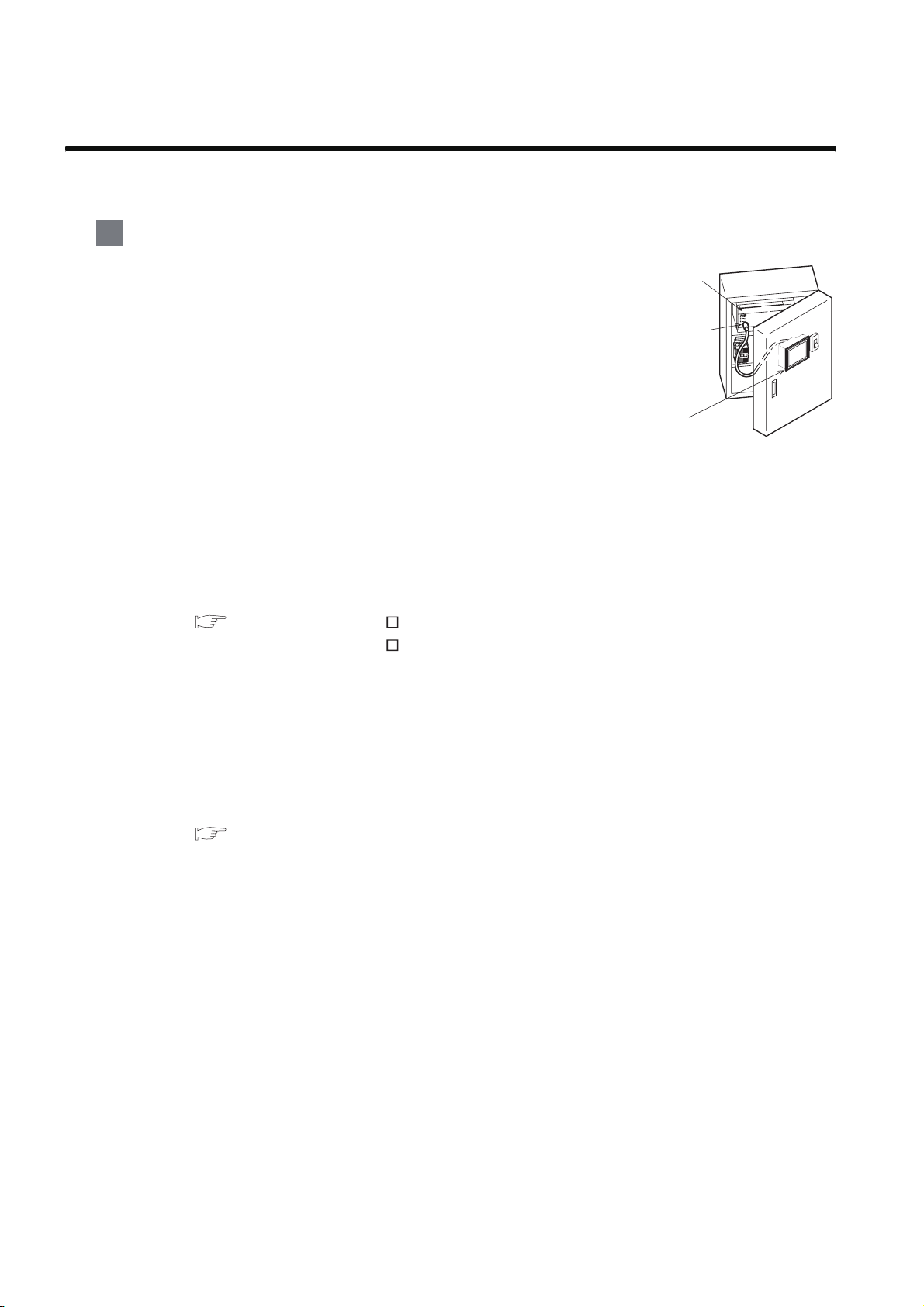
1 About GOT
A GOT is installed on the panel surface of a control panel or operating
panel and connects to the PLC within the control panel. The GOT
carries out switch operation, lamp display, data display, message
display, etc.
For the display screen, two kinds of screens are available : user screen
and utility screen.
PLC
Connector for
program
(1) User screen
The user screen is a screen drawn by drawing software.
The objects "Touch switch", "Lamp display", "Comment display", and "Numeric display" can be
arbitrarily arranged on the display.
A "horizontal format" or "vertical format" may be selected for displaying a user’s project.
Moreover, multiple screens created within drawing software can be individually selected or
overlapped for the display.
For details, refer to the following.
GT Designer2 Version Basic Operation/Data Transfer Manual
GT Designer2 Version Screen Design Manual
GT Designer3 Version1 Screen Design Manual
(2) Utility Screen
The utility screen is a factory drawn horizontal screen that cannot be edited.
The utility screen has options for "Contrast ", "Buzzer volume ", etc, and the format is horizontal
only.
For details, refer to the following.
Chapter 9 to Chapter 17
GOT
1 - 1

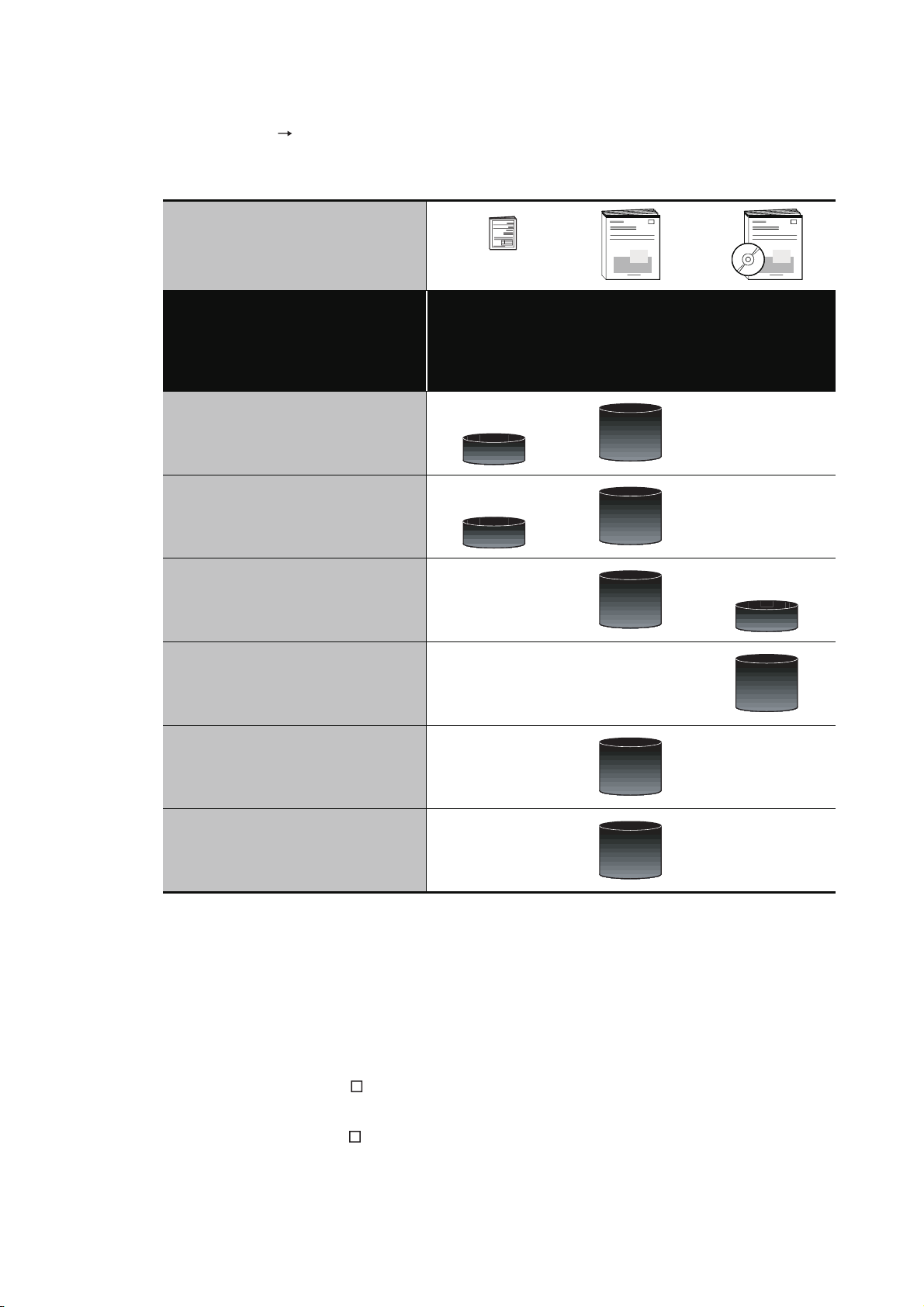
2 About Manual
The following manuals related to GOT 1000 series are available. Refer to each manual in accordance
with the intended use.
1
(1) Installation of the software programs Drawing Data transfer
For operations from creating project data to transferring data to GOT, refer to the following
manuals.
GT Designer2 Version
GT Designer2 Version
Screen Design Manual
GT Designer3 Version1
Screen Design Manual (Functions)
Purpose
Installing product on PC
Creating projects
Basic Operation/Data Transfer
GT Designer3 Version1
Screen Design Manual
(Fundamentals)
Manual
Detailed
Detailed
*1
*1
OVERVIEW
2
SYSTEM
CONFIGURATION
3
*1
*1
SPECIFICATIONS
4
PAR T NA M E
Creating screens
Drawing figures
Detailed
Detailed
Making Common Settings
Overview
Placing/Setting objects
Overview
Transferring data to GOT
*1 Stored in the GT Works 2/GT Designer2/GT Works 3/GT Designer3 in PDF format.
Detailed
Detailed
Detailed
5
UL, cUL
STANDARDS AND
EMC DIRECTIVE
6
INSTALLATION
7
WIRING
8
1 - 2
OPTION
(2) Installing a GOT connection to a PLC
For the operations from installing a GOT to communicating with a PLC CPU, refer to the following
manuals.
(Included)
GT15 General
Purpose
Description
GT11 General
Description
GT10 General
Description
GT15 User's Manual
GT11 User's Manual
GT10 User's Manual
GOT1000 Series
Connection Manual
*1
Confirming part names and
specifications of the GOT
Confirming the GOT installation
method
Confirming the mounting method for
communication units or option
devices
Confirming the PLC connection
method
Confirming the utility operation
method
Confirming error codes (system
alarm) displayed on the GOT
Detailed
Overview
Detailed
Overview
Detailed
Overview
Detailed
Detailed
Detailed
1 - 3
*1 Stored in the GT Works2/GT Designer2/GT Works 3/GT Designer3 in PDF format.
(3) Other manuals
The following manuals are also available.
The following manuals are stored in the GT Works2/GT Designer2/GT Works3/GT Designer3 in
PDF format.
(a) GOT1000 Series Gateway Functions Manual
Describes how to use the gateway function.
(b) GT Simulator 2 Version Operation Manual
Describes how to simulate the created project data with GT Simulator2.
(c) GT Converter2 Version Operating Manual
Describes how to use the GT Converter2.

1.1 Features
(1) Improved monitoring performance and connectivity to FA devices
• Multiple languages are displayed using the Unicode2.1-compatible fonts and beautiful characters
are drawn using the TrueType and high quality fonts
• For GT1020 and GT1030, 3 backlight colors (green, red, orange or white, red, pink) are available
for status displays
• For GT104 and GT105 , two types of display modes are available: 256 colors display and
monochrome
In the monochrome display, 16 scales are used to improve the display
• Improved layout design flexibility with the analog touch panel on the GT1020
• High speed monitoring through high speed communication at maximum of 115.2kbps
• High speed display and high speed touch switch response
(2) More efficient GOT operations including screen design, startup, adjustment, management and
maintenance works
• Recipe function, Device monitor function and FX list editor function (for GT104 , GT105 only)
are standard installed
• Factory-installed OS on the GOT
• For GT1020, GT1030 and GT104 , LED-type backlight is adopted (no replacement required)
• High speed data transfer of project data, OS and others using the USB interface (for GT104 ,
GT105 only)
1
OVERVIEW
2
SYSTEM
CONFIGURATION
3
SPECIFICATIONS
4
(3) Enhanced support of FA setup tools
• Transferring or monitoring the sequence programs using the personal computer connected to
GOT, during connection to A, L, Q, QnA, or FX series PLC CPU (Transparent function)
• Allows the connection of multiple GOT units via the serial interface when connected to the CPU
on the A, L, Q, QnA, or FX series of PLC
PAR T NA M E
5
UL, cUL
STANDARDS AND
EMC DIRECTIVE
6
INSTALLATION
7
1.1 Features
WIRING
8
OPTION
1 - 4
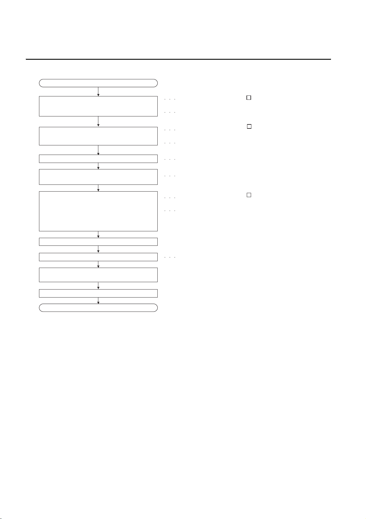
1.2 Rough Pre-operation Procedure
The outline procedure before operating GOT is shown.
Start
Refer to GT Designer2 Version
Install GT Designer2 or GT Designer3 in the PC.
Create project data.
Basic Operation/Data Transfer Manual.
Refer to GT Designer3 Version1
Screen Design Manual (Fundamentals)
Refer to GT Designer2 Version
Screen Design Manual.
Refer to GT Designer3 Version1
Screen Design Manual (Functions)
Wire for the GOT power supply.
Connect GOT and PC with a RS-232/USB
conversion adaptor or RS-232 cable.
1) Install a communication driver on the GOT that
is compatible with the controller.
(The communication driver for the FX series is
factory-installed.)
2) Install the project data that were created with
GT Designer2 or GT Designer3 on the GOT.
Check the communication settings.
Connect the GOT and the destination connector.
Turn on the GOT power and the system of the
connection destination.
Start the monitor. (Display each screen.)
End
Refer to Chapter 7 WIRING.
Refer to Chapter 8 OPTION.
Refer to GT Designer2 Version
Basic Operation/Data Transfer Manual.
Refer to GT Designer3 Version1
Screen Design Manual (Fundamentals)
Refer to GOT1000 Series Connection Manual.
1 - 5
1.2 Rough Pre-operation Procedure
 Loading...