

JY997D35801E
GT01-RS4-M
Serial Multi-Drop Connection Unit
USER’S MANUAL
Manual Number JY997D35801E
Date Jul. 2011
This manual describes the specifications of the product. Before use, read this
manual and manuals of relevant products fully to acquire proficiency in
handling and operating the product. Make sure to learn all the product
information, safety information, and precautions.
And, store this manual in a safe place so that you can take it out and read it
whenever necessary. Always forward it to the end user.
Registration
The company name and the product name to be described in this manual are
the registered trademarks or trademarks of each company.
Effective Jul. 2011
Specifications are subject to change without notice.
Safety Precaution
Before using this product, please read this manual and the relevant manuals
introduced in this manual carefully and pay full attention to safety to handle the
product correctly.
The precautions given in this manual are concerned with this product.
In this manual, the safety precautions are ranked as "DANGER" and "CAUTION".
Indicates that incorrect handling may cause hazardous
conditions, resulting in death or severe injury.
Indicates that incorrect handling may cause hazardous
conditions, resulting in medium or slight personal injury
or physical damage.
Depending on circumstances, procedures indicated by "CAUTION" may also be
linked to serious results.
In any case, it is important to follow the directions for usage.
DESIGN PRECAUTIONS
• Some failures of the Multi-Drop Connection Unit or cable may keep the
outputs on or off.
An external monitoring circuit should be provide d to check for output signals
which may lead to a serious accident.
Not doing so can cause an accident due to false output or malfunction.
• If a communication fault (including cable disconnection) occurs during
monitoring on the GOT, communication between the GOT and PLC CPU is
suspended and the GOT becomes inoperative.
A system where the GOT is used should be configured to perform any
significant operation to the sys tem by using the switches of a devi ce other
than the GOT on the assumption that a GOT communication fault will occur.
Not doing so can cause an accident due to false output or malfunction.
Do not use the
•
cause a serious accident.
An independent and redundant hardware or mechanical interlock is required to
configure the device that displays and outputs serious warning.
Failure to observe this instruction may result in an accident due to incorrect
output or malfunction.
DESIGN PRECAUTIONS
• Do not bundle the control and communication cables with main-circuit, power
or other wiring.
Run the above cables separately from such wiring and keep them a minimum
of 100mm (3.94in.) apart.Not doing so noise can cause a malfunction.
Multi-Drop Connection Unit
© 2009 Mitsubishi Electric Corporation
(Read these precautions before using.)
as the warning device that may
MOUNTING
PRECAUTIONS
• Be sure to shut off all phases of the external power supply used by the system
before mounting or removing the Multi-Drop Connection Unit to/from the panel.
Not doing so can cause the unit to fail or malfunction.
• When installing the battery wear an earth band etc. to avoid the static electricity.
The static electricity can cause the unit to fail or malfunction.
MOUNTING PRECAUTIONS
• Use the Multi-Drop Connection Unit in the environment that satisfies the general
specifications described in this manual. Not doing so can cause an electric s hock,
fire, malfunction or product damage or deterioration.
WIRING PRECAUTIONS
• Be sure to shut off all phases of the external power supply used by the system
before wiring. Failure to do so may result in an electric shock, product damage or
malfunctions.
• Please make sure to ground FG terminal of the Multi-Drop Connection Unit power
supply section by applying 100 or less which is used exclusively for the GOT. Not
doing so may cause an electric shock or malfunction.
• Correctly wire the Multi-Drop Connection Unit power supply section after
confirming the rated voltage and terminal arrangement of the product. Not doing
so can cause a fire or failure.
• Tighten the terminal screws of the Multi-Drop Connection Unit power supply
section in the specified torque range. Undertightening can cause a short circuit or
malfunction.
Overtightening can cause a short circuit or malfunction due to the damage of the
screws or the Multi-Drop Connection Unit.
• Exercise care to avoid foreign matter such as chips and wire offcuts entering the
Multi-Drop Connection Unit. Not doing so can cause a fire, failure or malfunction.
WIRING PRECAUTIONS
• Plug the communication cable into the connector of the connected unit and
tighten the mounting and terminal screws in the specified torque range.
Undertightening can cause a short circuit or malfunction. Overtightening can
cause a short circuit or malfunction due to the damage of the screws or unit.
STARTUP/MAINTENANCE
PRECAUTIONS
• Do not disassemble or modify the Multi-Drop Connection Unit.
Doing so can cause a failure, malfunction, injury or fire.
• Do not touch the conductive and electronic parts of the Multi-Drop Connection
Unit directly.
Doing so can cause a Multi-Drop Connection Unit malfunction or failure.
• The cables connected to the Multi-Drop Connection Unit must be run in ducts or
clamped.
Not doing so can cause the Multi-Drop Connection Unit or cable to be damaged
due to the dangling, motion or accidental pulling of the cables or can cause a
malfunction due to a cable connection fault.
• When unplugging the cable connected to the unit, do not hold and pull the cable
portion. Doing so can cause the uni t or cable to be damaged or can cause a
malfunction due to a cable connection fault.
• Do not drop or apply any impact to the battery.
If any impact has been applied, discard the battery and never use it.
The battery may be damaged by the drop or impact.
• Before touching the unit, always touch grounded metal, etc. to discharge static
electricity from human body, etc.
Not doing so can cause the Multi-Drop Connection Unit to fail malfunction.
DISPOSAL PRECAUTIONS
• When disposing of the product, handle it as industrial waste.
TRANSPORTATION
PRECAUTIONS
• Make sure to transport the Multi-Drop Connection Unit main unit and/or relevant
unit(s) in the manner they will not be exposed to the impact exceeding the impact
resistance described in the general specifications of this manual, as they are
precision devices. Failure to do so may cause the unit to fail.
Check if the unit operates correctly after transportation.
Compliance with EC directive (CE Marking)
This note does not guarantee that an entire mechanical module produced in
accordance with the contents of this note will comply with the following standards.
Compliance to EMC directive for the entire mechanical module should be checked
by the user / manufacturer. For more details please contact the local Mitsubishi
Electric sales site.
Attention
• This product is designed for use in industrial applications.
• Manufactured by: Mitsubishi Electric Corporation
• Manufactured at: Mitsubishi Electric Corporation Himeji Works
• Authorized Representative in the European Community:
Associated Manuals
The following manuals are relevant to this product. When these loose manuals are required, please consult with our local distributor.
GOT1000 Series Connection Manual 1/3, 2/3, 3/3
GOT1000 Series Connection Manual (Mitsubishi Products)
for GT Works3
GT Designer2 Version2 Basic Operation/Data Transfer Manual
(For GOT1000 Series)
GT Designer2 Version2 Screen Design Manual
(For GOT1000 Series) 1/3, 2/3, 3/3
GT Designer3 Version1 Screen Design Manual
(For GOT1000 Series)
(Fundamentals) 1/2, 2/2
2-7-3 Marunouchi, Chiyoda-ku, Tokyo 100-8310 Japan
840 Chiyoda-machi, Himeji, Hyogo 670-8677 Japan
Mitsubishi Electric Europe B.V.
Gothaer Str. 8, 40880 Ratingen, Germany.
Manual Name
Manual Number
(Model Code)
SH-080532ENG
SH-080868ENG
SH-080529ENG
SH-080530ENG
SH-080866ENG
(1D7M26)
(1D7MC2)
(1D7M24)
(1D7M25)
(1D7MB9)
Requirement for Compliance with EMC directive
The following products have shown compliance through direct testing (to the
identified standards) and design analysis (forming a technical construction file) to the
European Directive for Electromagnetic Compatibility (2004/108/EC) when used as
directed by the appropriate documentation.
Type :Programmable Controller (Open Type Equipment)
Standard Remark
Compliance with all rel evant aspects of the
EMI
EN61131-2 : 2007
Programmable
controllersEquipment,
requirement and tests
For more details please contact the local Mitsubishi Electric sales site.
Describes system configurations of connection methods applicable to GOT1000
series and cable creation methods
Describes system configurations of connection methods applicable to GOT1000
series and cable creation methods
Describes methods of the GT Designer2 installation operation, basic operation for
drawing and transmitting data to GOT1000 series
Describes specifications and settings of the object functions used in GT Designer2
Describes methods of the GT Designer3 installation operation, basic operation for
drawing and transmitting data to GOT1000 series
standard. (Radiated Emissions)
Compliance with all rel evant aspects of the
standard.
EMS
(ESD, RF electromagneti c field, EFTB, Surge,
RF conducted disturbances and Power
frequency magnetic field)
Description
Bundled Items
Included Item Number of Items
GT01-RS4-M main unit 1
Power supply cable with connectors 1
GT01-RS4-M Serial Multi-Drop Connection Unit USER’S MANUAL (this manual) 1
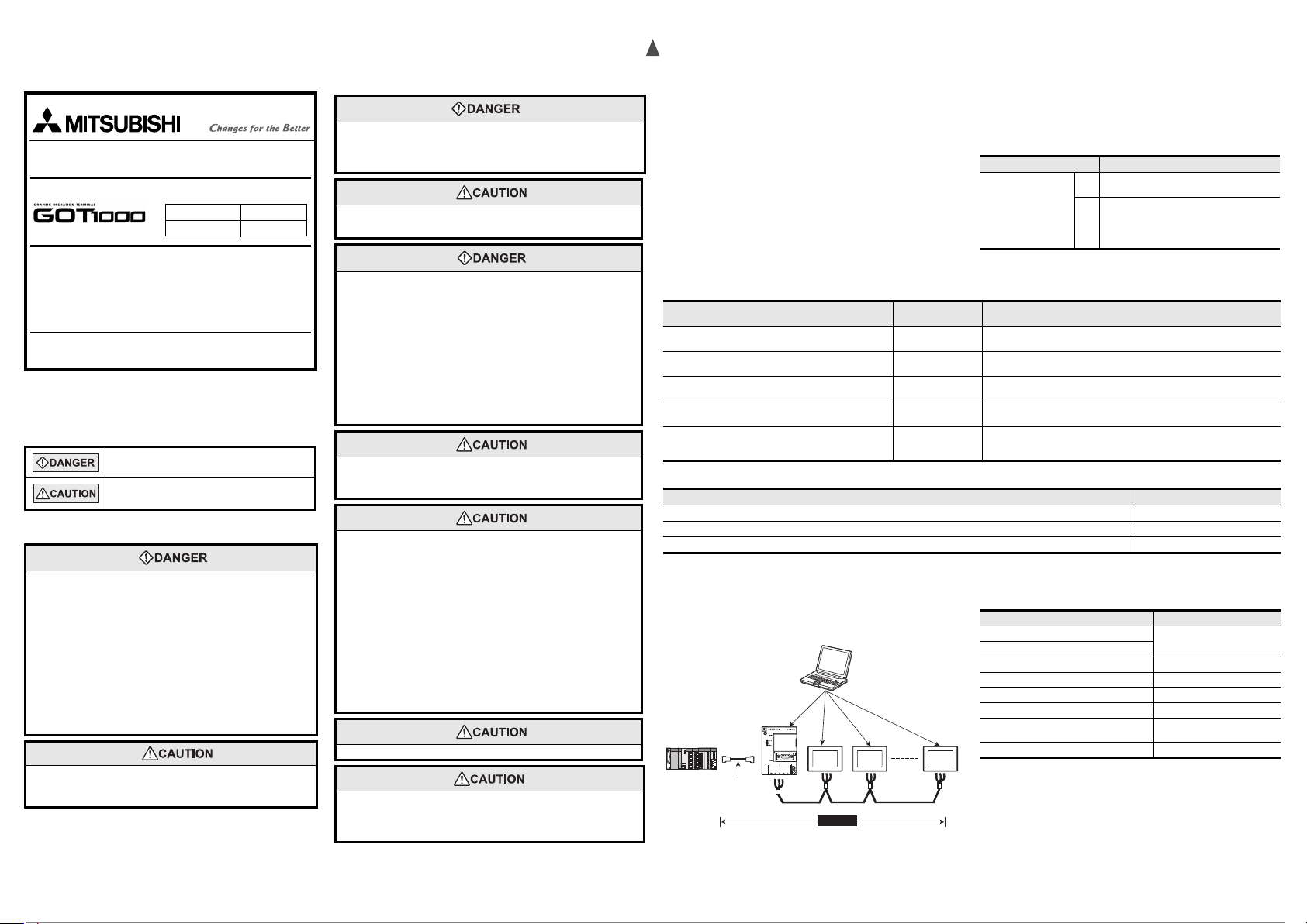
1. System Configuration
1.1 System Configuration
GOT multi-drop connection is a communication method for 1:N communication by
connecting multiple GOTs to one PLC, using the GT01-RS4-M serial multi-drop
connection module.
For details of the system configuration, refer to the GOT1000 Series Connection
Manual.
• GT Designer2
• GT Designer3
• Communication driver
• Communication interface
Serial multi drop connection module
Connect to the PLC.
Varies according to
the connection type.
MAX500m
1.2 Compatible PLC
For PLCs compatible with the GOT multi-drop connection, refer to the GOT1000
Series Connection Manual.
• Communication driver
• Communication interface
RS-485 cable
1.3 Compatible GOT
The followings are the GOTs compatible with the GOT multi-drop connection.
For the confirmation method of the hardware version, refer to the User's Manual of
each GOT.
GT1 6
GT1 5
GT1155-QTBD Version C or later
GT1155-QSBD, GT1150-QLBD Version F or later
GT1055-QSBD, GT1050-QBBD Version C or later
GT1045-QSBD, GT1040-QBBD Version A or later
GT1030-LBD/LWD, GT1030-LBDW/LWDW
GT1030-HBD/HWD, GT1030-HBDW/HWDW
GT1020-LBD/LWD, GT1020-LBDW/LWDW Version E or later
1.4 Compatible drawing software version
GT Designer2 Version2 (Ver.2.93X or later)
GT Designer3 Version1 (Ver.1.01B or later) (Ver.1.14Q or later is applicable to GT16
and GT15.)
GOT Hardware version
Version A or later
Version B or later
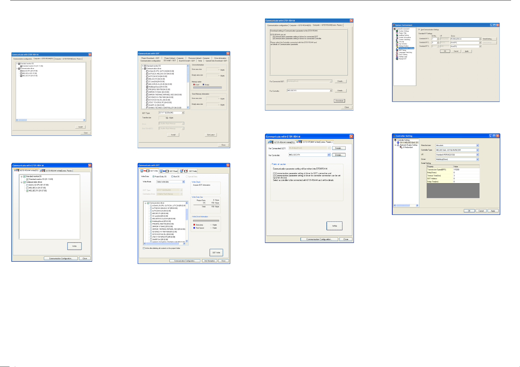
2. Outline Procedure
The outline procedure is shown below.
GT11 installation follows.
1) Install the OS.
• Install the communication driver of the PLC connected to the multi-drop connection module.
• Install the communication driver (multi-drop (Slave)) to the GOT.
For details of the installation method, refer to the GT Designer2 Version2 Basic Operation/Data Transfer Manual or GT Designer3 Version1 Screen Design Manual.
- For GT Designer2
(For multi-drop connection module)
(For GOT)
- For GT Designer2
(For multi-drop connection module)
- For GT Designer3
(For multi-drop connection module) (For GOT)
(For GOT)
- For GT Designer3
(For multi-drop connection module)
2) Make sure that the OS is installed.
Check GT Designer2 or GT Designer3 drive information to know if the OS is properly installed in the GOT.
For details, refer to the GT Designer2 Version2 Basic Operation/Data Transfer Manual or GT Designer3 Version1 Screen Design Manual.
3) Set the communication interface.
• For the multi-drop connection module, set the communication interface in the communication setting with GT01-RS4-M of GT Designer2 or GT Designer3.
• For the GOT, set the communication interface in the Communication Settings of GT Designer2 or GT Designer3.
For details, refer to the GT Designer2 Version2 Basic Operation/Data Transfer Manual or GT Designer3 Version1 Screen Design Manual.
(For GOT)
4) Download the project data.
For instructions on how to download the project data, refer to the GT Designer2 Version2 Basic Operation/Data Transfer Manual or GT Designer3 Version1 Screen Design
Manual.
5) Connect the cable.
For details of the cable connection, refer to the GOT1000 Series Connection Manual.
 Loading...