

Mitsubishi Electric GS2110-WTBD, GS2107-WTBD General Description Manual
Side
JY997D518BDC
B
Side
A
CHINESE ENGLISH
Side
B
GS2110-WTBD, GS2107-WTBD
GS21 General Description
Manual Number JY997D518BDC
Date Dec. 2013
This manual describes the part names, dimensions, mounting, and
specifications of the product. Before use, read this manual and manuals o f
relevant products fully to acquire proficiency in handling and operating the
product. Make sure to learn all the product information, safety information, and
precautions.
And, store this manual in a safe place so that you can take it out and read it
whenever necessary. Always forward it to the end user.
Registration
Ethernet is a trademark of Xerox Corporation in the United States.The company
name and the product name to be described in this manual are the registered
trademarks or trademarks of each company.
Effective Dec. 2013
Specifications are subject to change without notice.
Safety Precaution
Before using this product, please read this manual and the relevant manuals
introduced in this manual carefully and pay full attention to safety to handle the
product correctly.
The precautions given in this manual are concerned with this product.
In this manual, the safety precautions are ranked as "WARNING" and
"CAUTION".
Indicates that incorrect handling may cause hazardous
conditions, resulting in death or severe injury.
Indicates that incorrect handling may cause hazardous
conditions, resulting in medium or slight personal injury
or physical damage.
Depending on circumstances, procedures indicated by "CAUTION" may also be
linked to serious results. In any case, it is important to follow the directions for
usage
DESIGN PRECAUTIONS
Some failures of the GOT or cable may keep the outputs on or off. Some
failures of a touch panel may cause malfunction of the input objects such as a
touch switch. An external monitoring circuit should be provided to check for
output signals which may lead to a serious accident. Not doing so can cause
an accident due to false output or malfunction.
Do not use the GOT as the warning device that may cause a serious
accident. An independent and redundant hardware or mechanical interlock is
required to configure the device that displays and outputs serious warning.
Not doing so can cause an accident due to false output or malfunction.
When the GOT detects its backlight failure, the GOT disables the input
operation on the touch switch(s). Thus, operators cannot operate the GOT
with touches. The GOT backlight failure can be checked with a system si gnal
of the GOT.
Even when the display section has dimmed due to a failure of the liquid
crystal section or the backlight on the GOT, the input operation of the touch
switches may still be enabled. This may cause an incorrect operation of the
touch switches. For example, if an operator assumes that the display section
has dimmed because of the screen save function and touches the display
section to cancel the screen save, a touch switch may be activated.h
touches. The GOT backlight failure can be checked with a system signal of
the GOT.
The display section of the GOT is an analog-resistive type touch panel.
Simultaneous pressing of two or more areas on the display section may
activate the switch between those areas. Do not press two or more areas
simultaneously on the display se ction. Doing so may cause an acc ident due
to incorrect output or malfunction.
When programs or parameters of the controller (such as a PLC) that is
monitored by the GOT are changed, be sure to shut off the power of the GOT
promptly and power on the GOT again. Not doing so can cause an accident
due to false output or malfunction.
If a communication fault (including cable disconnection) occurs during
monitoring on the GOT, communication between the GOT and PLC CPU is
suspended and the GOT becomes inoperative. A system where the GOT is
used should be configured to perform any significant operation to the system
by using the switches of a device other than the GOT on the assumption that
a GOT communication fault will occur. Not doing so can cause an accident
due to false output or malfunction.
2013 Mitsubishi Electric Corporation
(Read these precautions before using.)
DESIGN PRECAUTIONS
Do not bundle the control and communication cables with main-circuit, power or
other wiring. Run the above cables separately from such wiring and keep them a
minimum of 100mm apart. Not doing so noise can cause a malfunction.
Do not press the GOT display section with a pointed material as a pen or driver.
Doing so can result in a damage or failure of the display section.
When the GOT is connected to the Ethernet network, the available IP address is
restricted according to the system configuration.
- Wh en multiple GOTs are connected to the Ethernet network: Do not set the IP
address (192.168.3.18) for the GOTs and the controllers in the network.
- Wh en a single GOT is connected to the Ethernet network: Do not set the IP
address (192.168.3.18) for the controllers except the GOT in the network.
Doing so can cause the IP address duplication. The duplication can negatively
affect the communication of the device with the IP address (192.168.3.18). The
operation at the IP address duplication depends on the devices and the
system.
Turn on the controllers and the network devices to be ready for communication
before they communicate with the GOT. Failure to do so can cause a
communication error on the GOT.
When the GOT is subject to shock or vibration, or some colors appear on the
screen of the GOT, the screen of the GOT might flicker.
MOUNTING PRECAUTIONS
Be sure to shut off all phases of the external power supply used by the system
before mounting or remov ing the GOT main unit to/ from the panel. Not doing so
can cause the unit to fail or malfunction.
MOUNTING PRECAUTIONS
Use the GOT in the environment that satisfies the general specifications
described in this manual.Not doing so can cause an electric shock, fire,
malfunction or product damage or deterioration.
When mounting the GOT to the control panel, tighten the mounting screws in the
specified torque range (0.36N·m to 0.48N·m) with a Phillips-head screwdriver
No.2. Undertightening can cause the GOT to drop, shor t circuit or malfunction.
Overtightening can cause a drop , short circuit or malfunction du e to the damage
of the screws or the GOT.
Remove the protective film of the GOT. When the user continues using the GOT
with the protective film, the film may not be removed.
Operate and store the GOT in environments without direct sunlight, high
temperature, dust, humidity, and vibrations.
Do not use the GOT in an environment with oil or chemicals. Doing so may cause
failure or malfunction due to the oil or chemical entering into the GOT.
WIRING PRECAUTIONS
Be sure to shut off all phases of the external power supply used by the system
before wiring. Failure to do so may result in an electric shock, product damage or
malfunctions.
WIRING PRECAUTIONS
Please make sure to ground FG terminal of the GOT power supply section by
applying 100Ω or less which is used exclusively for the GOT. Not doing so may
cause an electric shock or malfunction.
Correctly wire the GOT power supply section after confirming the rated voltage
and terminal arrangement of the product. Not doing so can cause a fire or failure.
Tighten the terminal screws of the GOT power supply section in the specified
torque range (0.5N•m to 0.6N•m) . Undertightening can cause a short circuit or
malfunction. Overtightening can cause a short circuit or malfunction due to the
damage of the screws or the GOT.
Exercise care to avoid foreign matter such as chips and wire offcuts entering the
GOT. Not doing so can cause a fire, failure or malfunction.
Plug the communication cable into the GOT interface or the connector of the
connected unit, and tighten the mounting screws and the terminal screws in the
specified torque range. Undertighten ing can cause a short circuit or malfunctio n.
Overtightening can cause a short circuit or malfunction dueto the damage of the
screws or unit.
TEST OPERATION
PRECAUTIONS
Before performing the test operations of the user creation monitor screen (such as
turning ON or OFF bit device, changi ng the word device current value, c hanging
the settings or current values of the timer or counter, and changing the buffer
memory current value), read through the manual carefully and make yourself
familiar with the operation m ethod. During test operatio n, never change the data
of the devices which are used to perform significant operation for the system.
False output or malfunction can cause an accident.
STARTUP/MAINTENANCE
PRECAUTIONS
When power is on, do not touch the terminals. Doing so can cause an electric
shock or malfunction.
Before starting cleaning or terminal screw retightening, always switch off the
power externally in all phases. Not doing so can cause the unit to fail or
malfunction. Undertight ening can cause a short cir cuit or malfunction.
Overtightening can cause a short circuit or malfunction due to the damage of the
screws or unit.
STARTUP/MAINTENANCE
PRECAUTIONS
Do not disassemble or modify the unit. Doing so can cause a failure,
malfunction, injury or fire.
Do not touch the conductive and electronic parts of the unit directly. Doing so
can cause a unit malfunction or failure.
The cables connected to the unit must be run in ducts or clamped. Not doing so
can cause the unit or cable to be damaged due to the dangling, motion or
accidental pulling of the cables or can cause a malfunction due to a cable
connection fault.
When unplugging the cable connected to the unit, do not hold and pull from the
cable portion. Doing so can cause the unit or cable to be damaged or can cause
a malfunction due to a cable connection fault.
Do not drop the module or subject it to strong shock. A module damage may
result.
Before touching the unit, always touch grounded metals, etc. to discharge static
electricity from human body, etc. Not doing so can cause the unit to fail or
malfunction.
TOUCH PANEL
PRECAUTIONS
For the analog-resistive film type touch panels, normally the adjustment is not
required.However, the difference between a touched position and the object
position may occur as the period of use elapses. When any difference between
a touched position and the ob ject position occurs, exec ute the touch panel
calibration.
When any difference between a touched position and the object position occurs,
other object may be activated. This may cause an unexpected operation due to
incorrect output or malfunction.
PRECAUTIONS WHEN THE
DATA STORAGE IS IN USE
If the SD card mounted on drive A of the GOT is removed while the GOT is
accessed, processing for the GOT might be interrupted about for 20 seconds.
The GOT cannot be operated during this period. The functions that run in the
background including a screen updating, alarm, logging, scripts, and others are
also interrupted. Since this interruption makes an impact to the system
operation, it might cause failure. After inhibiting access to the SD card on the
GOT utility screen, check that the SD card access LED is off and remove the SD
card.
PRECAUTIONS WHEN THE
DATA STORAGE IS IN USE
If the data storage mounted on the GOT is removed while the GOT is accessed,
the data storage and files are damaged. To remove the data storage from the
GOT, check that the access to the data storage in SD card access LED, the
system signal, and others is not performed.
When removing the SD card from the GOT, make sure to support the SD card
by hand as it may pop out. Failure to do so may cause the SD card to drop from
the GOT, resulting in a failure or break.
Before removing the USB device from the GOT, follow the procedure for
removal on the utility screen of the GOT. After the successful completion dialog
is displayed, remove the USB device by hand carefully. Failure to do so may
cause the USB device to drop from the GOT, resulting in a failure or break.
DISPOSAL PRECAUTIONS
When disposing of this product, treat it as industrial waste.
TRANSPORTATION
PRECAUTIONS
Make sure to transport the GOT main unit and/or relevant unit(s) in the manner
they will not be exposed to the impact exceeding the impact resistance
described in the general specifications of this manual, as they are precision
devices. Failure to do so may cause the unit to fail. Check if the unit operates
correctly after transportation.
When fumigants that contain halogen materials such as fluorine, chlorine,
bromine, and iodine are used for disinfecting and protecting wooden packaging
from insects, they cause malfunction when entering our products. Please take
necessary precautions to ensure that remaining materials from fumigant do not
enter our products, or treat packaging with methods other than fumigation (heat
method). Additionally, disinfect and protect wood from insects before packing
products.
Associated Manuals
The following manuals are relevant to this product. When these loose manuals are
required, please consult with our local distributor.
Manual name Contents
GT Works3 Installation
Instructions
GOT SIMPLE series User's
*1
Manual
(sold separately)
GT Designer3 (GOT2000) Help
GOT2000 Series Connection
Manual (Mitsubishi Products) for
GT Works3 Version1
(sold separately)
GOT2000 Series Connection
Manual (Non-Mitsubishi Products
1) for GT Works3 Version1*
(sold separately)
GOT2000 Series Connection
Manual (Non-Mitsubishi Products
2) for GT Works3 Version1*
(sold separately)
GOT2000 Series Connection
Manual (Microcomputer, MODBUS Products, Peripherals) for GT
Works3 Version1*
(sold separately)
*1 The manual in PDF-format is included in the GT Works3/GT Designer3 products.
For details of a PLC to be connected, refer to the PLC user's manual respectively.
*1
1
Installation Instructions BCN-P5999-0066
Describes the Handy GOT
hardware-relevant content
such as part names,
external dimensions,
mounting, power supply
wiring, specifications, and
introduction to option
devices
Describes methods of the
GT Designer3 basic
operation for drawing,
transmitting data to GOT
SIMPLE series, and
specifications and settings
of the object functions
used in GT Designer3
Describes system
configurations of
connection methods
applicable to GOT2000
series and cable creation
methods
Describes system
configurations of
connection methods
1
applicable to GOT2000
series and cable creation
methods
Describes system
configurations of
connection methods
1
applicable to GOT2000
series and cable creation
methods
Describes system
configurations of
connection methods
applicable to GOT2000
series and cable creation
methods
Manual Number
(Model Code)
JY997D52901
-
SH-081197ENG
(1D7MJ8)
SH-081198ENG
(1D7MJ9)
SH-081199ENG
(1D7MK1)
SH-081200ENG
(1D7MK2)
Bundled Items
Model Name Specifications
GS2110-WTBD
GS2107-WTBD
Mounting fitting 4
GS21 General Description (This manual) 1
10"[800 480 dots], TFT color (65536 colors), 24VDC,
Memory size 9MB, Ethernet interface built-in
7"[800 480 dots], TFT color (65536 colors), 24VDC,
Memory size 9MB, Ethernet interface built-in
Bundled item Quantity
1. Specifications
1.1 General Specifications
Operating ambient temperature 0 to 50C
Storage ambient temperature -20 to 6 0C
Operating/Storage ambient humidity
Vibration resistance
Shock resistance
Operating atmosphere
Operating altitude
Overvoltage category
Pollution degree
Cooling method Self-cooling
Grounding Class D grounding (100Ω or less), To be connected to the panel when grounding is not possible.
*1 Do not use or store the GOT under pressures higher than the atmospheric pressure of altitude 0m (0ft). Failure to observe this instruction may cause a malfunction.
When the air inside the control panel is purged by pressurization, the surface sheet may be lifted by high pressure. As a result, the touch panel may be difficult to press,
and the sheet may be peeled off.
*2 This indicates the section of the power supply to w hich the equipment is assumed to be connected between the public electrical power distribution network and the
machinery within the premises. Category II applies to equipment f or which electrical power is supplied from fixed facilities. The surge voltage withstand level for up to the
raged voltage of 300V is 2500V.
*3 This index indicates the degree to which conductive pollution is generated in the environment where the equipment is used. In pollution degree 2, only non-conductive
pollution occurs but temporary conductivity may be produced due to condensation.
1.2 Performance Specifications
Display
*1
section
Backlight
Touch
*2
panel
Memory C drive
Built-in
interface
Buzzer output
Protective structure
External dimensions W272(10.71) H214(8.43) D56(2.21) [mm] (inch) W206(8.11) H155(6.11) D50(1.97) [mm] (inch)
Item Specifications
10 to 90%RH, non-condensing (The wet bulb temperature is 39°C)
When the ambient temperature exceeds 40°C, maintain the absolute humidity at 40°C and 90%.
Conforms to
IEC 61131-2
Conforms to IEC 61131-2 (147m/s
Must be free of lamp black, corrosive gas, flammable gas, or excessive amount of electro conductive dust particles.
*1
*2
*3
Item
Type TFT color liquid crystal display
Screen size 10" 7"
Resolution 800 480 dots
Display size W222(8.74) H132.5(5.22) [mm](inch) (Horizontal format) W154(6.06) H85.9(3.38) [mm](inch) (Horizontal format)
Display character 16-dot standard font: 50 characters 30 lines (Horizontal format)
Display color 65536 colors
Brightness 32-level adjustment
Type Analog-resistive film type
Key size Minimum 2 2 [dots] (per key)
Number of points touched
simultaneously
Life 1 million times (operating force 0.98N max.)
RS-422
RS-232
Ethernet
USB
SD card
*3
Must be no direct sunlight. (Same as for saving)
2000m (6562ft) max.
or less
2 or less
LED-type (no replacement required)
Backlight off/screen saving time can be set.
Simultaneous 2-point presses prohibited (Only one point can be touched.)
Flash memory (Internal) (9Mbytes), for storing project data, OS
Life (Number of write times) 100,000times
RS-422, 1ch
Transmission speed: 115200/57600/38400/19200/9600/4800bps
Connector shape: D-sub 9 pins (Female)
Application: For communicating with controllers
Terminating resistor: 330Ω fixed
RS-232, 1ch
Transmission speed: 115200/57600/38400/19200/9600/4800bps
Connector shape: D-sub 9 pins (Male)
Application: For communication with controllers and a bar code reader
For PC connection (Project data upload/download, FA transparent function)
Data Transfer method: 100BASE-TX, 10BASE-T, 1ch
Connector shape: RJ-45 (modular jack)
Application: For communication with controllers
For PC connection (Project data upload/download, FA transparent function)
USB (Full Speed 12Mbps) 1ch
Connector shape: Mini-B
Application: For PC connection (Project data upload/download, FA transparent function)
Conforms to the SD standard, 1ch
Supported memory card: SDHC memory card, SD memory card
Application: Project data upload/download, logging data save
Single tone (LONG/SHORT/OFF adjustable)
IP65F (only the front part of the panel)
Under intermittent
vibration
Under continuous
vibration
GS2110-WTBD GS2107-WTBD
Frequency Acceleration Half-amplitude Sweep Count
5 to 8.4Hz -- 3.5mm
8.4 to 150Hz 9.8m/s
5 to 8.4Hz -- 1.75mm
8.4 to 150Hz 4.9m/s
2
, 3times each in the X, Y, and Z directions)
Specifications
2
2
--
--
10times each in X,
Y and Z directions
--
Item
Panel cutting dimensions W258(10.16) H200(7.88) [mm] (inch) (Horizontal format) W191(7.52) H137(5.40) [mm](inch) (Horizontal format)
Weight Approx. 1.3kg (Excluding mounting fixtures) Approx. 0.9kg (Excluding mounting fixtures)
Compatible software package
(Version of GT Designer3)
*1 Bright dots (always lit) and dark dots (unlit) may appear on a liquid crystal display panel. It is impossible to completely avoid this symptom, as the liquid crystal display
comprises of a great number of display elements. Flickers and partial discoloration may be generated on the liquid crystal display panel due to individual differences of
panels. Please note that these phenomena appear due to its characteristic and are not caused by product defect.
*2 The touch panel is an analog-resistive type. Simultaneous pressing of two or more areas on the touch panel may activate the switch between those areas. Do not press
two or more areas simultaneously on the touch panel.
*3 Note that this does not guarantee all users ' operation environment. In addition, the product may not be used in environments under exposition of oil or chemicals for a
long period of time, or in environments filled with oil-mist.
Version1.104J or later
GS2110-WTBD GS2107-WTBD
Specifications
1.3 Power Supply Specifications
Item
Input power supply voltage 24VDC (+10% -15%), ripple voltage 200mV or less
Power consumption 7.6W (317mA/24V) or less 6.5W (271mA/24V) or less
At backlight off 3.8W (158mA/24V) or less 3.8W (158mA/24V) or less
Inrush current 17A or less (6ms, 25°C, at the maximum load)
Permissible instantaneous power failure time
Noise immunity Conforms to IEC61000-4-4, 2kV (power supply line)
Dielectric withstand voltage 350VAC for 1 minute (across power supply terminals and earth)
Insulation resistance 500VDC across power terminals and earth, 10 MΩ or more by an insulation resistance tester
Within 5ms
2. GT Works3 Version1 (compatible with GS Series) Installation Procedure
This chapter explains how to install and uninstall GT Works3 Version1 (compatible
with the GS Series). Make sure to read this chapter before introducing GT Works3
Version1 (compatible with the GS Series) into the personal computer.
2.1 Before installation
1) Prepare the product disc (CD-ROM or DVD-ROM) of GT Works3 Version 1.104J
or later at hand.
2) Install GT Designer3 (GOT2000) Version 1.104J or later in advance.
* For using the GS Series in the data transfer tool, it is necessary to install
in advance the data transfer tool Version 3.02C or later. For installation of
GT Designer3 (GOT2000)/data transfer tool, refer to "GT Works3
Version1 Installation Procedure" packed together with the product disc of
GT Works3 Version 1.104J or later.
3) GS Installer storage place
The installer is stored in the following folder saved in the product disc (CD-ROM or
DVD-ROM) of GT Works3 Version 1.104J or later:
CD-ROM:<Root>\TOOL\GS\GS Installer.exe
DVD-ROM:<Root>\Disk1\TOOL\GS\GS Installer.exe
4) For installing GS Installer, set to OFF the automatic playback function of the drive
before inserting the product disc into the drive, or finish the started installation if
GT Works3 Installer was automatically started by the automatic playback function.
2.2 Installation procedure
2.3 Uninstallation procedure
When GT Designer3 (GOT2000) is uninstalled, the GS Series is automatically
uninstalled.For uninstallation of GT Designer3 (GOT2000), refer to "GT Works3
Version1 Installation Procedure" packed together with the product disc of GT Works3
Version 1.104J or later.
1. Click GS Installer (GS Installer.exe) in
the folder shown in 2.1(3) above to start
GS Installer.Operate the personal
computer in accordance with
instructions given on the screen.
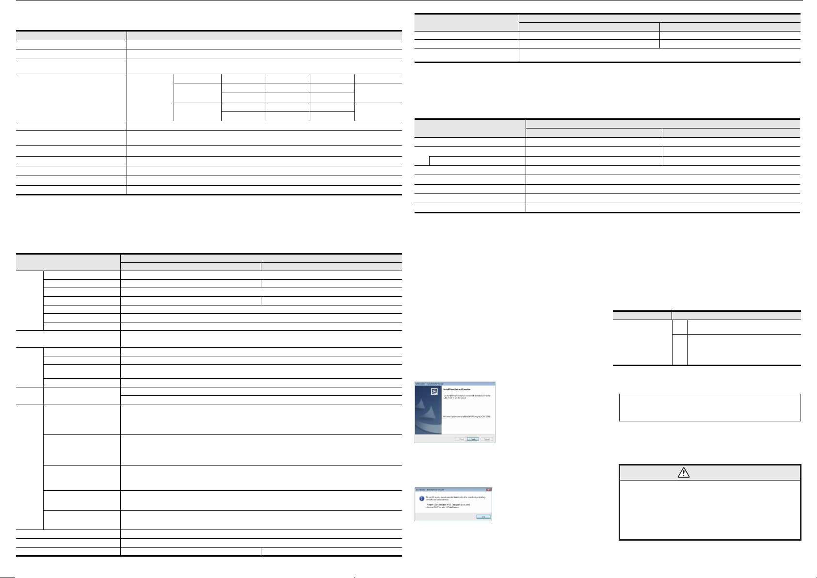
2. When the completion screen shown on
the left appears, click the [Finish] button
to quit GS Installer.
GS2110-WTBD GS2107-WTBD
This product is designed for use in industrial applications
Manufactured by: MITSUBISHI ELECTRIC AUTOMATION MANUFACTURING
Manufactured at: MITSUBISHI ELECTRIC AUTOMATION MANUFACTURING
Authorized Representative in the European Community:
EN61131-2 : 2007
Programmable
controllers - Equipment,
requirements and tests
For more details please contact your local Mitsubishi Electric sales site.
For details of CE marking, refer to the following.
GOT SIMPLE series User's Manual
2.4 Precautions
When the following screen appears after
startup of GS Installer, operate the
personal computer in accordance with
instructions given on the screen.
3. Notification of CE marking
The following products have shown compliance through direct testing (to the
identified standards) and design analysis (forming a technical construction file) to the
European Directive for Electromagnetic Compatibility (2004/108/EC) when used as
directed by the appropriate documentation.
Specifications
(CHANGSHU) CO.,LTD.
No.3 Southeast Road, Changshu New & Hi-tech Industrial
Development Zone of Jiangsu, 215500 China
(CHANGSHU) CO.,LTD.
No.3 Southeast Road, Changshu New & Hi-tech Industrial
Development Zone of Jiangsu, 215500 China
Mitsubishi Electric Europe B.V.
- Type: Graphic Operation Terminal
- Models : GOT SIMPLE series
Standard Remark
This manual confers no industrial property rights or any rights of any other kind,
nor does it confer any patent licenses. Mitsubishi Electric Corporation cannot be
held responsible for any problems involving industrial property rights which may
occur as a result of using the contents noted in this manual.
Warranty
Mitsubishi will not be held liable for damage caused by factors found not to be
the cause of Mitsubishi; opportunity loss or lost profits caused by faults in the
Mitsubishi products; damage, secondary damage, accident compensation
caused by special factors unpredictable by Mitsubishi; damages to products
other than Mitsubishi products; and to other duties.
Gothaer Str. 8, 40880 Ratingen, Germany.
Compliance with all relevant aspects of the
EMI
standard. (Radiated Emissions)
Compliance with all relevant aspects of the
standard.
EMS
(ESD, RF electromagnetic field, EFTB, Surge, RF
conducted disturbances and Power frequency
magnetic field)
For safe use
This product has been manufactured as a general-purpose part for general
industries, and has not been designed or manufactured to be incorporated in
a device or system used in purposes related to human life.
Before using the product for special purposes such as nuclear power, electric
power, aerospace, medicine or passenger movement vehicles, consult with
Mitsubishi Electric.
This product has been manufactured under strict quality control. However
when installing the product where major accidents or losses could occur if the
product fails, install appropriate backup or failsafe functions in the system.
MITSUBISHI ELECTRIC
AUTOMATION MANUFACTURING (CHANGSHU) CO.,LTD.
No.3 Southeast Road, Changshu New & Hi-tech Industrial Development Zone of Jiangsu, 215500 China
 Loading...