

Page 1

0-1
GROUP 0
GENERAL
CONTENTS
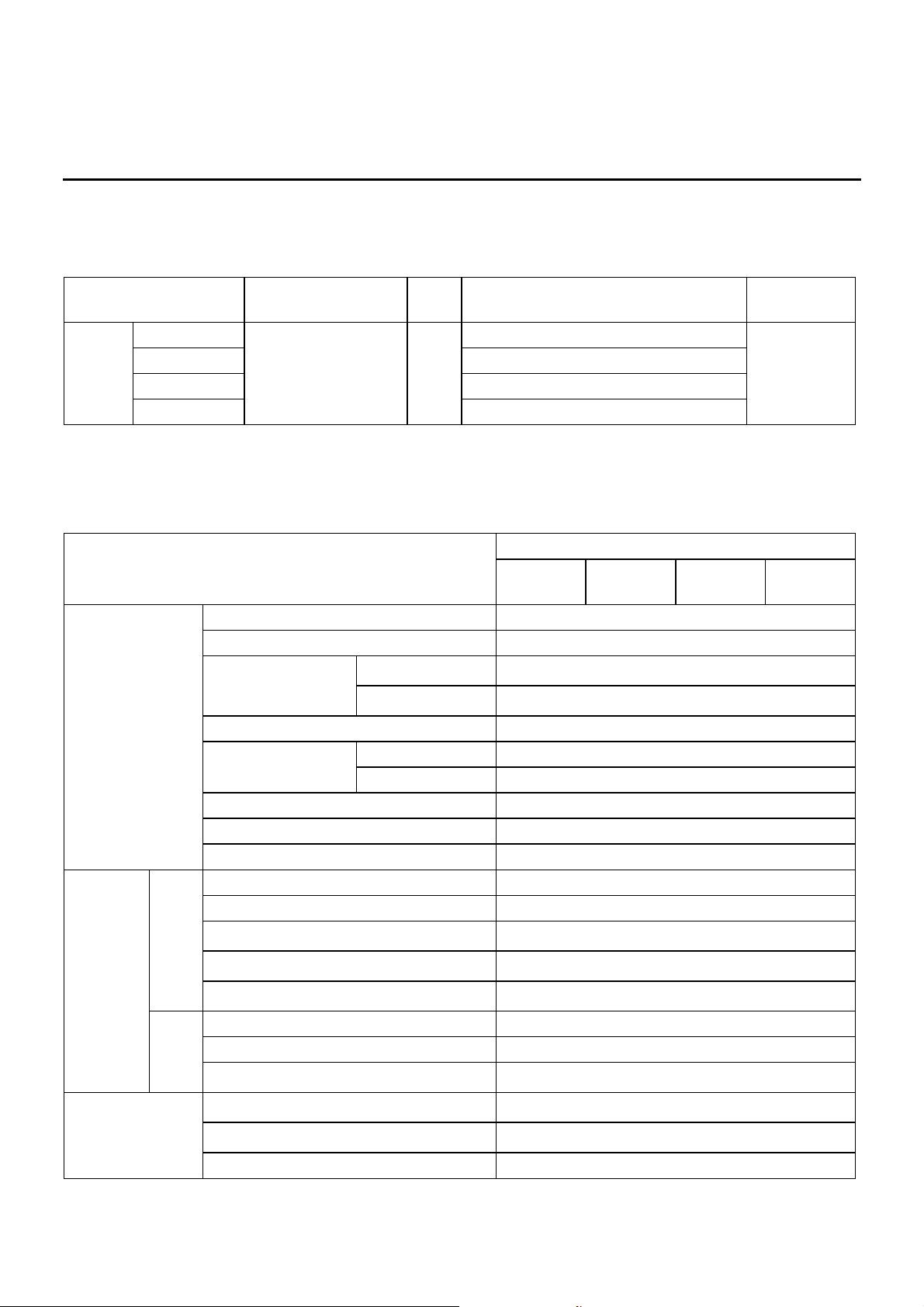
VEHICLE IDENTIFICATION . . . . . . . 0-2 MAJOR SPECIFICATIONS . . . . . . . . 0-2
Page 2
VEHICLE IDENTIFICATION
GENERAL
0-2
VEHICLE IDENTIFICATION
M4000001000264
MODELS
MAJOR SPECIFICATIONS
M4000003000174
Model code Engine model Price
class
Transmission model Fuel supply
system
NA4W LNUYL6/R6 4G69-SOHC-MIVEC
(2,378 mL)
GLX F5M42 <2WD, 5M/T> MPI
LRUYL6/R6 F4A4B <2WD, 4A/T with sport mode>
LNHYL6/R6 F5M42 <2WD, 5M/T>
LRHYL6/R6 F4A4B <2WD, 4A/T with sport mode>
Item NA4W
LNUYL6/R6LNHYL6/R6LRUYL6/R6LRHYL6/
R6
Vehicle
dimension mm
Overall length 4,765
Overall width 1,795
Overall height Without roof rails
1,655/1,665
*1
With roof rails
1,690/1,700
*1
Wheelbase 2,830
Track Front 1,550
Rear 1,555
Front overhang 900
Rear overhang 1,035
Ground clearance 155
Vehicle
wheel
alignment
Front Toe-in (at the centre of tyre tread) mm 0 ± 3
Toe angle (per wheel) 0°00' ± 08'
Camber
*3
0°00' ± 30'
Caster
*3
2°46' ± 1°00', 2°54' ± 1°00'
*1
Kingpin inclination angle
13°12' ± 1°30', 12°54' ± 1°30'
*1
Rear Toe-in (at the centre of tyre tread) mm 3 ± 2
Toe angle (per wheel) 0°08' ± 05'
Camber
*3
-0°45' +45'/-15', -0°05' ± 30'
*1
Wheels and tyres Tyre size
215/60 R16 95H, 215/55 R17 94V
*2
Wheel size
16 × 6 1/2JJ, 17 × 7JJ
*2
Offset mm 46
Page 3

MAJOR SPECIFICATIONS
GENERAL
0-3
NOTE: .
*1
: Vehicles with high ground suspensions <LH drive vehicles>.
*2
: Vehicles with aluminium wheels.
*3
: Difference between right and left wheels must be less than 30'.
Page 4

1-1
GROUP 1
BODY
CONSTRUCTION
CONTENTS
BODY COMPONENTS. . . . . . . . . . . . 1-2
BODY MAIN CROSS-SECTIONAL VIEWS
. . . . . . . . . . . . . . . . . . . . . . . . . . . . . . . . . 1-4
MAINTENANCE, SERVICEABILITY . 1-6
BODY CONSTRUCTION CHARACTERISTICS
. . . . . . . . . . . . . . . . . . . . . . . . . . . . . . . . . 1-7
FRONT BODY. . . . . . . . . . . . . . . . . . . . . . . 1-7
SIDE BODY. . . . . . . . . . . . . . . . . . . . . . . . . 1-12
REAR BODY . . . . . . . . . . . . . . . . . . . . . . . . 1-14
ROOF . . . . . . . . . . . . . . . . . . . . . . . . . . . . . 1-15
UNDER BODY. . . . . . . . . . . . . . . . . . . . . . . 1-16
DOOR . . . . . . . . . . . . . . . . . . . . . . . . . . . . . 1-19
SILENCER APPLICATION LOCATIONS
. . . . . . . . . . . . . . . . . . . . . . . . . . . . . . . . . 1-20
LOCATIONS USING URETHANE FOAM AND
FOAM MATERIAL . . . . . . . . . . . . . . . 1-21
STIFFENER AND DAMP SHEET
APPLICATION LOCATIONS . . . . . . . 1-22
Page 5
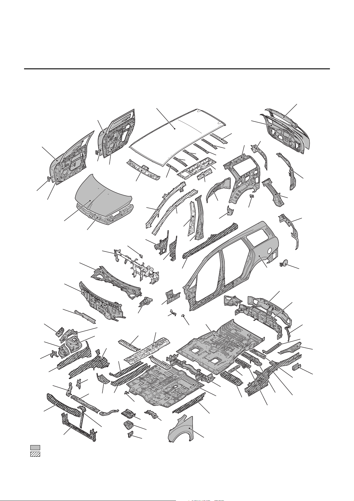
BODY COMPONENTS
BODY CONSTRUCTION
1-2
BODY COMPONENTS
M4010001000221
AB301830
AB
1
2
3*
4
5
6
7
8*
9*
10*
11*
12
13
14
15
16
17
18
19
20
21
22
23
24
25*
26
27
28
29
30
31
41
51
61
71*
72
73
74*
75
76
77
78
70
62
63
64
65
66
67
68
69
60
52
53
54
55
56
57
58
59
50
40
42
43
44
45
46
47
48
49
32
33
34
35
36
37
38
39
79
80
81
82
84
85
86
83
: High-tensile steel panels (*: Indicates 590MPa-high-tensile steel panels.)
: Anti-corrosion steel panels
1. Front end crossmember
2. Hood lock stay
3. Front end beam
4. Front end upper bar
5. Front upper bar side
6. Headlamp support brace upper
Page 6

BODY COMPONENTS
BODY CONSTRUCTION
1-3
7. Dash panel extension
8. Front floor sidemember
9. Front floor sidemember reinforcement
10. Front sidemember inner
11. Front sidemember outer
12. Headlamp bracket
13. Front fender shield
14. Spring house panel
15. Front upper frame inner
16. Front upper frame outer
17. Dash panel crossmember upper
18. Dash panel
19. Upper frame extension
20. Front deck
21. Deck crossmember
22. Guide bracket
23. Front pillar inner lower
24. Front pillar reinforcement outer lower
25. Side sill reinforcement
26. Centre pillar reinforcement outer
27. Centre pillar inner
28. Front pillar reinforcement outer upper
29. Front pillar inner upper
30. Hood inner panel
31. Hood outer panel
32. Front door panel inner
33. Front door side door beam
34. Front door panel outer
35. Rear door panel inner
36. Rear door side door beam
37. Rear door panel outer
38. Roof panel
39. Front roof rail
40. Roof bow A
41. Roof bow B
42. Roof bow C
43. Roof bow D
44. Roof bow E
45. Rear roof rail
46. Tailgate panel inner
47 Tailgate panel outer
48 Quarter extension inner
49. Quarter inner panel
50. Roof reinforcement centre
51. Roof side rail inner
52 Rear wheel house inner panel
53. Shield plate front
54. Shield plate rear
55 Rear pillar reinforcement outer
56. Gate pillar reinforcement
57. Quarter extension outer
58 Fuel filler door panel
59. Side outer panel
60. Rear end outer panel
61 Rear end inner panel
62 Quarter inner extension lower
63. Seat pan reinforcement
64. Rear floor side pan
65 Rear floor side member rear extension
66. Rear floor crossmember D
67. Rear floor sidemember
68. Rear floor crossmember C
69. Rear floor crossmember B
70. Front stringer
71. Rear floor crossmember A
72. Front floor crossmember rear
73. Front floor pan
74. Front floor side sill
75. Front fender
76. Front floor crossmember front centre
77. Buttery tray stay
78. Buttery bracket
79. Buttery tray
80. Foot rest bracket
81. Front floor crossmember front
82. Back bone reinforcement
83. Rear floor pan
84. Front fender bracket
85. Front fender bracket lower
86. Front floor side sill inner front
Page 7
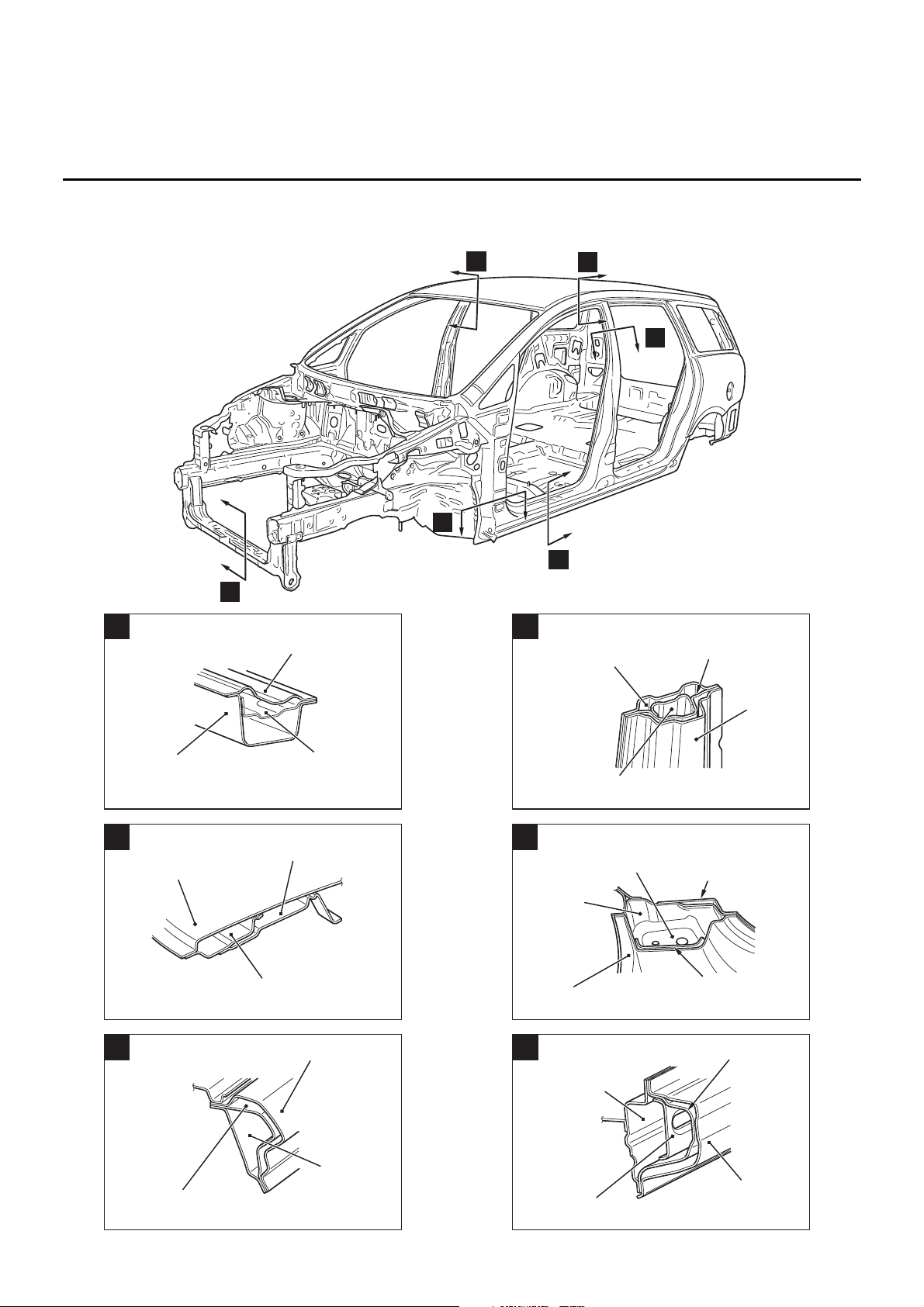
BODY MAIN CROSS-SECTIONAL VIEWS
BODY CONSTRUCTION
1-4
BODY MAIN CROSS-SECTIONAL VIEWS
M4010002000246
AB300191
AD
A
B
D
E
C
F
AB300345
AC
A
Front end
crossmember lower
Front end
crossmember upper
Front end crossmember
reinforcement
AB300343
AC
B
Roof panel
Over head console bracket
Front roof rail inner
AB300344
AC
C
Side outer panel
Front pillar
reinforcement outer upper
Side roof
rail inner
AB300346
AC
D
Centre pillar
reinforcement outer
Seat belt anchor
reinforcement
Centre pillar inner
Side outer
panel
AB300347
AD
Front floor
side sill
inner front
Side outer panel
Front pillar
reinforcement
bulkhead lower
Front door hinge
reinforcement lower
E
Front floor side sill
reinforcement upper
AB300348
AC
Side outer panel
Front floor
side sill inner
Side sill
reinforcement front
Side sill reinforcement
F
Page 8
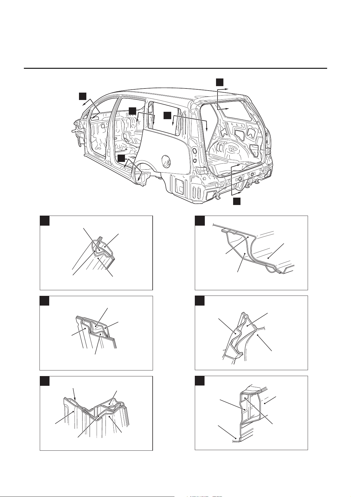
BODY MAIN CROSS-SECTIONAL VIEWS
BODY CONSTRUCTION
1-5
AB300192
AD
G
H
I
J
K
L
AB300349
Front pillar
inner upper
Front pillar reinforcement
outer upper
Side outer panel
AC
G
Front pillar support
(Drivers side)
AB300351
Seat belt reinforcement
rear pillar
Side outer
panel
Rear pillar reinforcement
H
AE
Quarter inner
panel
AB300352
Side
outer panel
Quarter inner panel
Gate pillar
reinforcement
Quarter outer
extension
AC
Quarter inner
extension upper
I
AB300350
Rear roof rail outer
Rear roof
rail inner
Roof panel
AC
J
AB300353
AC
Side outer panel
Quarter inner panel
K
Rear wheel house inner
front panel
AB300354
Rear floor pan
Rear end panel
inner
Rear end
panel outer
Tailgate striker
reinforcement
AC
L
Page 9
MAINTENANCE, SERVICEABILITY
BODY CONSTRUCTION
1-6
MAINTENANCE, SERVICEABILITY
M4010003000238
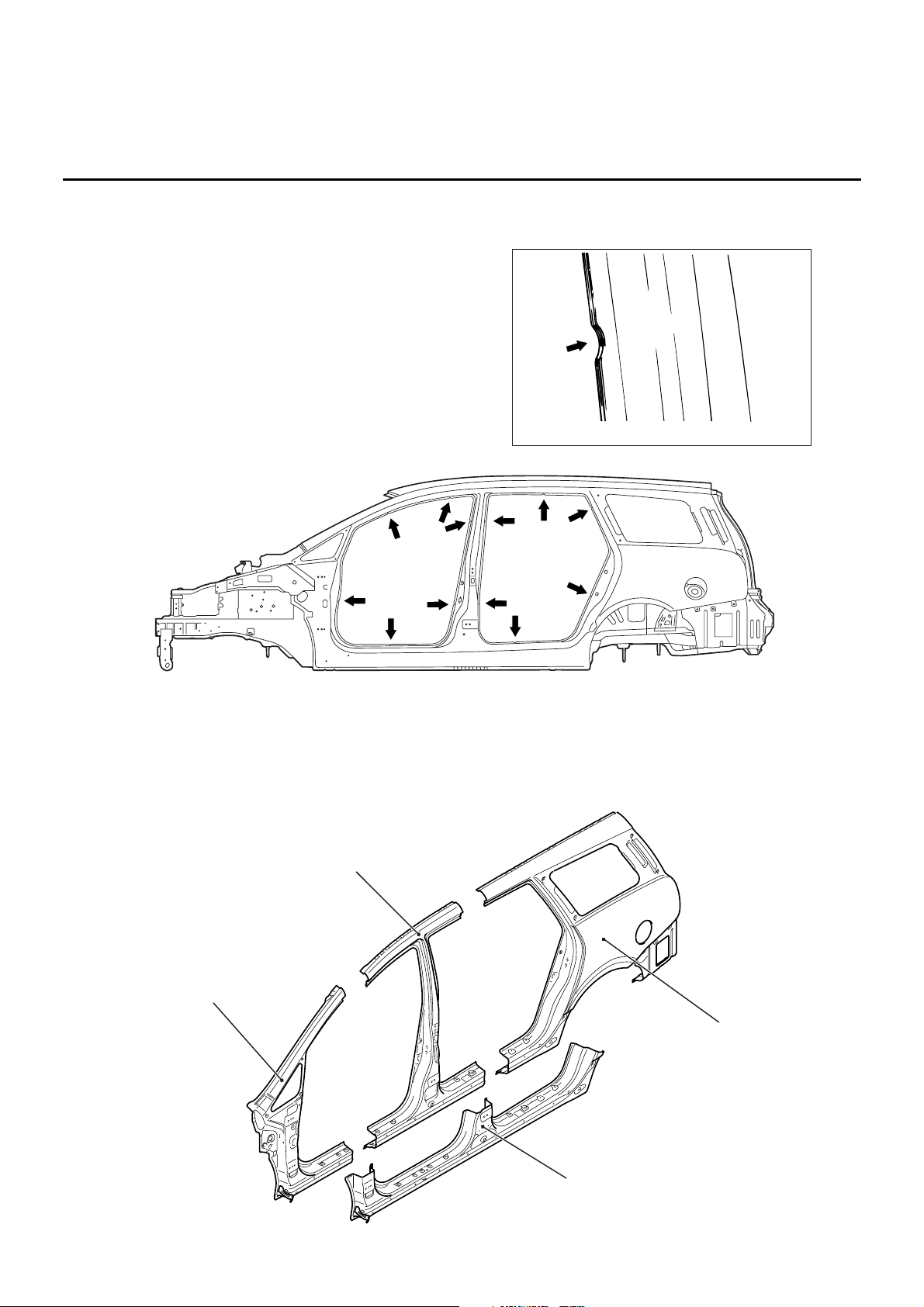
SIDE STRUCTURE
A panel positioning notch has been added on the
door opening to improve assembling workability
when replacing the panel.
SIDE OUTER PANEL
The extra parts are supplied in 4 different cut forms
as a result of employing the integrated side-frame
side outer panel.
AB301701
AB
Panel positioning notch
AB301702
AB
AB301703
Quarter outer
Floor side sill outer
Centre pillar outer
Front pillar outer
AB
Page 10
BODY CONSTRUCTION CHARACTERISTICS
BODY CONSTRUCTION
1-7
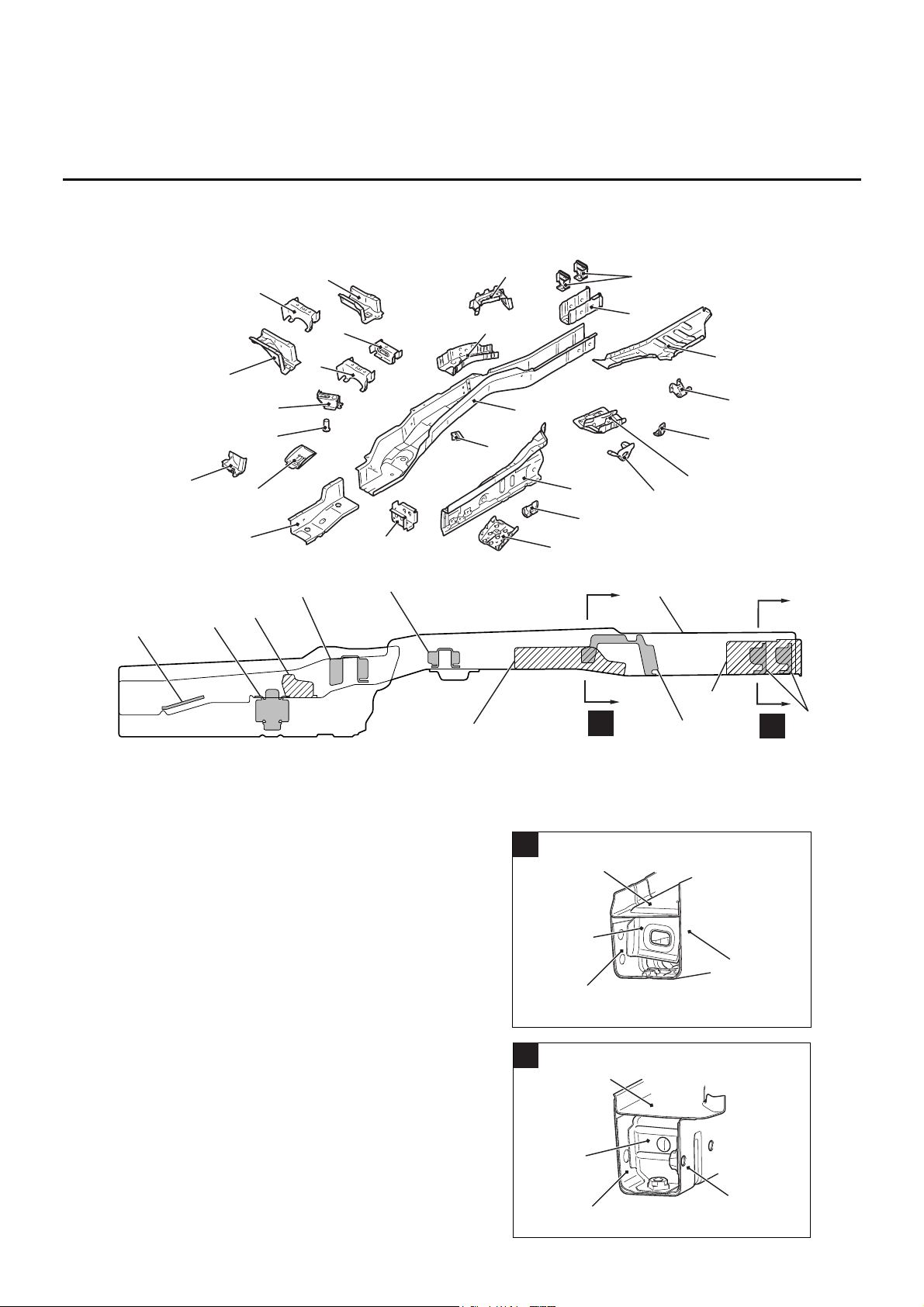
BODY CONSTRUCTION CHARACTERISTICS
FRONT BODY
M4010010000263
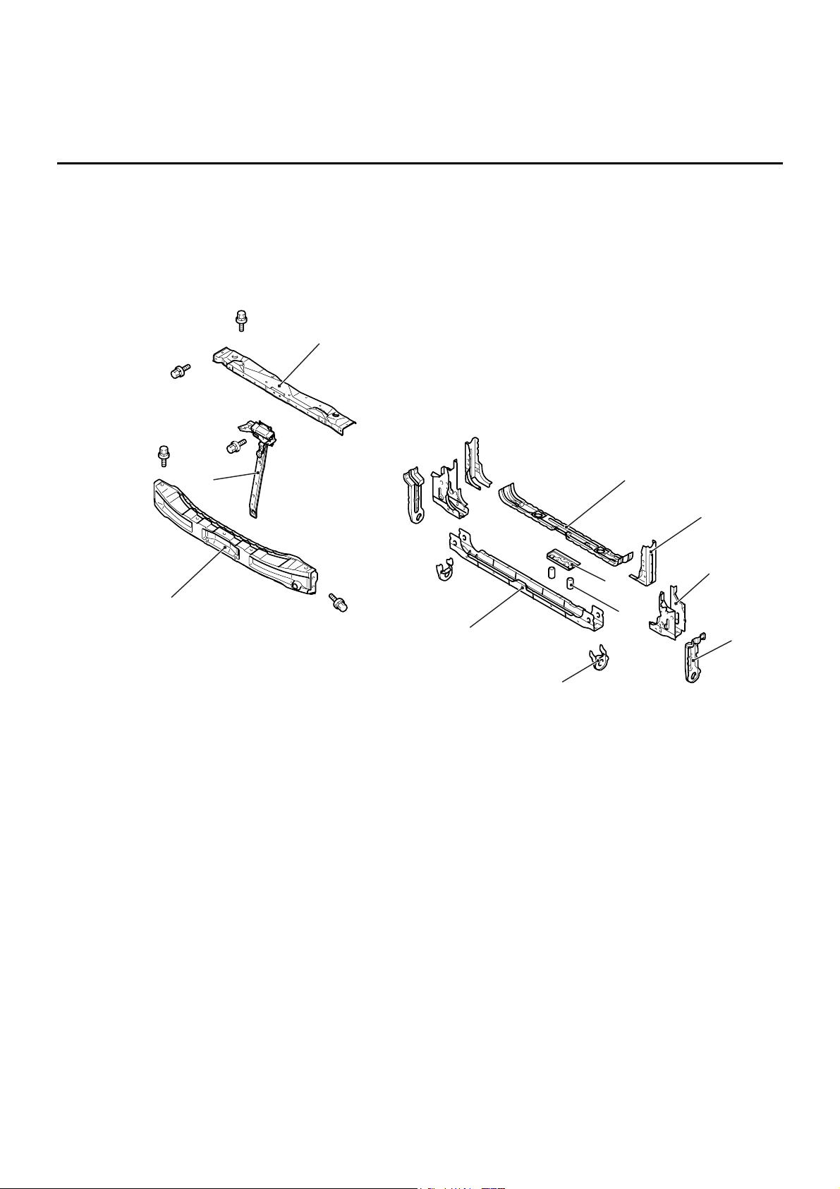
HEADLAMP SUPPORT
• A front end beam with a large cross section has
been adopted to improve safety upon impact.
• The bolt-on front end beam, bolt-on hood lock
stay and bolt-on front end upper bar are used to
improve maintainability.
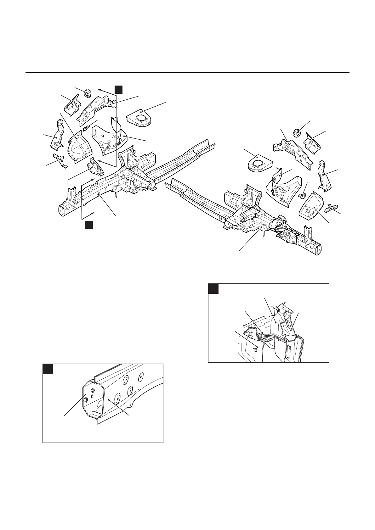
FENDER SHIELD
• The front frame structure is supported in three
directions by the front floor side members with a
large section, dash braces and dash upper
crossmember (dash panel area) to improve body
rigidity.
• An uneven thickness steel sheet* in which the
sheet thickness is thicker in the forward part of
the vehicle was employed for the front side
member reinforcement to ensure safety upon
impact and improve body rigidity.
NOTE: *: A steel sheet of varying thickness that is
welded into one steel sheet.
AB301705
AB
1
2
3
4
5
9
8
7
6
10
11
1. Front end beam
2. Hood lock stay
3. Front end upper bar
4. Front end crossmember upper
5. Headlamp support brace lower
6. Front end crossmember brace
7. Shipping bracket
8. Front end crossmember reinforcement
9. Front No2 crossmember pipe
10. Shipping reinforcement
11. Front end crossmember lower
Page 11
BODY CONSTRUCTION CHARACTERISTICS
BODY CONSTRUCTION
1-8
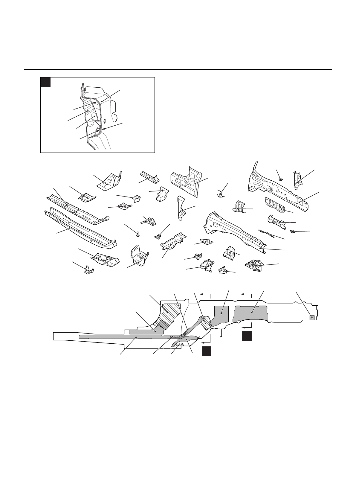
The front part of the front side member has octagonal
section that efficiently absorbs energy upon impact.
The coupling between the cowl tops with a large
cross section and the spring house brackets has
been strengthened to heighten body rigidity of the
suspension assembling support area and improve
driving stability.
AB301677
AB
Light side
Right side
A
B
1
10
4
3
5
6
9
2
3
5
8
1
4
6
7
8
7
11
10
11
12
1. Front sidemember
2. Engine mount reinforcement (Right side)
3. Headlamp bracket
4. Front end upper bar side
5. Front fender shield
6. Front upper frame outer
7. Upper frame bulkhead front
8. Front upper frame inner
9. Power steering reservoir tank bracket (Right side)
10. Spring house bracket
11. Spring house panel
12. Relay box bracket (Left side)
AB301688
AB
A
Front sidemember
inner
Front sidemember
outer
AB301689
AB
B
Spring house
bracket
Cowl top
panel inner
Cowl top
panel outer
Spring house
panel
Page 12
BODY CONSTRUCTION CHARACTERISTICS
BODY CONSTRUCTION
1-9
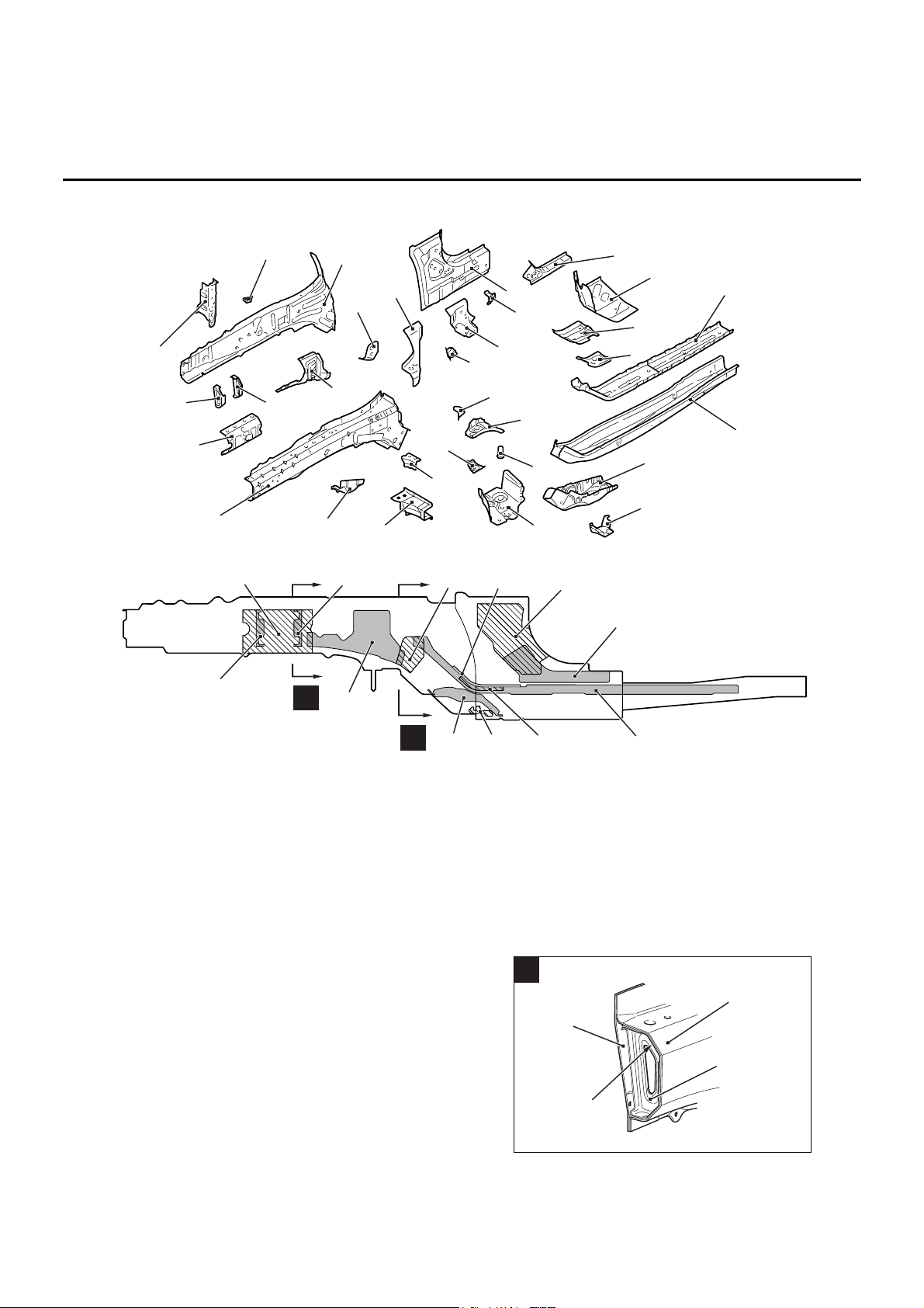
FRONT SIDEMEMBER REINFORCEMENT
AB302050
AB
Right side
1
2
3
4
5
7
8
9
10
11
12
13
14
15
16
19
20
27
22
6
29
25
28
26
21
30
23
24
18
17
AB300245
AC
A
B
3
9
19
15
12
25
4
5
2
18
27
17
1. Front sidemember inner
2. Front sidemember inner reinforcement front
3. Pipe support front
4. Engine mounting bulkhead rear
5. Engine mounting bulkhead front
6. Headlamp support brace upper
7. Brake hose bracket
8. Front sidemember outer
9. Kick up reinforcement
10. Dash brace
11. Accel stopper bracket (R.H. drive vehicles)
12. Front floor side sill inner reinforcement upper
13. Hood opener bracket (R.H. drive vehicles)
14. Front floor side sill inner front
15. Front floor side sill inner reinforcement lower
16. Dash panel extension
17. Front floor sidemember reinforcement upper
18. Front floor sidemember reinforcement middle (R.H.
drive vehicles)
19. Front floor sidemember reinforcement
20. Front floor sidemember
21. Suspension crossmember bracket rear
22. Dash crossmember extension lower
23. Front sidemember brace lower
24. Pipe nut
25. Pipe support rear
26. Accel pedal bracket (R.H. drive vehicles)
27. Stay reinforcement
28. Dash crossmember upper reinforcement extension
(R.H. drive vehicles)
29. Dash crossmember extension upper
30. Suspension crossmember bracket front
AB301690
AB
A
1
8
4
2
Page 13
BODY CONSTRUCTION CHARACTERISTICS
BODY CONSTRUCTION
1-10
AB302054
AB
B
1
9
8
19
3
10
AB302049
Light side
1
2
3
4
6
9
10
11
12
13
14
15
16
17
18
20
22
23
24
25
26
27
AB
28
29
30
31
33
32
8
7
5
19
21
AB302053
A
B
AB
18
4
10
9
30
31
20
13
17
5
7
1. Dash crossmember extension lower
2. Suspension crossmember bracket rear
3. Front floor sidemember
4. Front floor sidemember reinforcement
5. Front floor sidemember reinforcement upper
6. Dash panel extension
7. Front floor sidemember reinforcement middle (L.H.
drive vehicles)
8. Dash crossmember upper reinforcement extension
(L.H. drive vehicles)
9. Front floor side sill inner reinforcement lower
10. Front floor side sill inner reinforcement upper
11. Dash brace
12. Front floor side sill inner front
13. Kick up reinforcement
14. Brake house bracket
15. Headlamp support brace upper
16. Front sidemember outer
17. Towing reinforcement
18. Transmission mounting reinforcement
19. Front sidemember outer reinforcement (L.H. drive
vehicles)
20. Pipe support front
21. Front sidemember inner reinforcement (L.H. drive
vehicles)
22. Front sidemember inner
23. Battery bracket
24. Transmission mounting stay front
25. Transmission mounting gusset
26. Transmission mounting bracket
27. Transmission mounting stay rear
28. Suspension crossmember bracket front
29. Dash crossmember extension upper
30. Stay reinforcement
Page 14
BODY CONSTRUCTION CHARACTERISTICS
BODY CONSTRUCTION
1-11
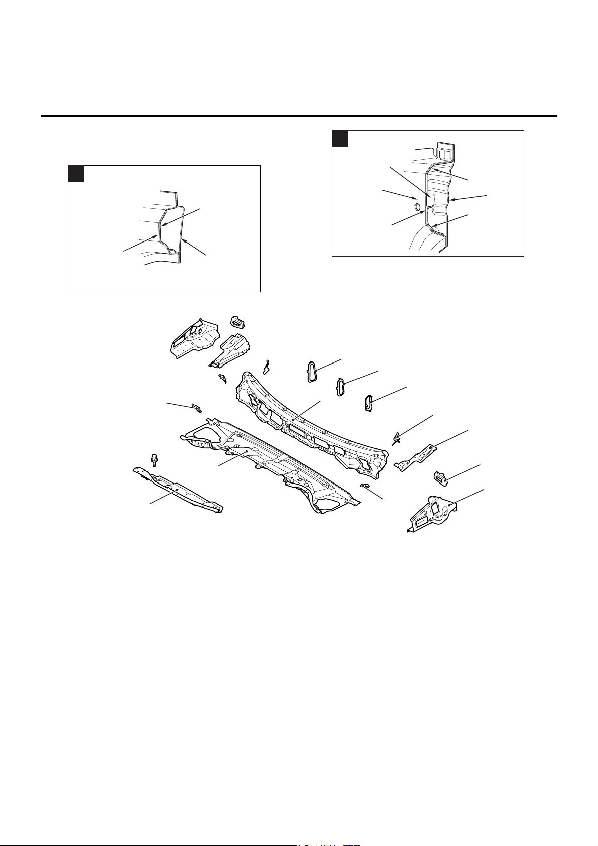
FRONT DECK
31. Pipe support rear
32 Pipe nut
33. Front sidemember brace lower
AB302055
AB
22
16
18
A
AB302056
AB
22
16
11
B
13
20
4
AB301706
2
3
5
6
AB
7
8
9
12
4
10
11
1
1. Cowl top panel front
2. Cowl top panel inner
3. Wiper bracket A
4. Cowl top bulkhead A
5. Cowl top panel outer
6. Cowl top bulkhead B
7. Cowl top bulkhead C
8. Cowl top gusset side
9. Front upper frame extension inner
10. Upper frame bulkhead rear
11. Front upper frame extension outer
12. Fender bracket
Page 15
BODY CONSTRUCTION CHARACTERISTICS
BODY CONSTRUCTION
1-12
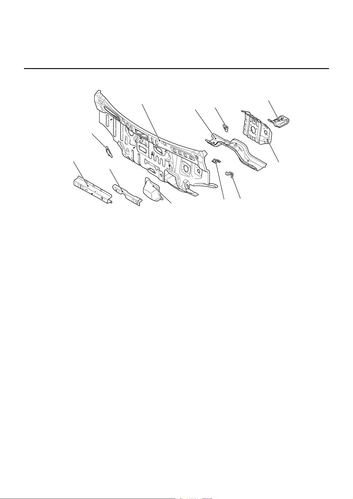
DASH PANEL
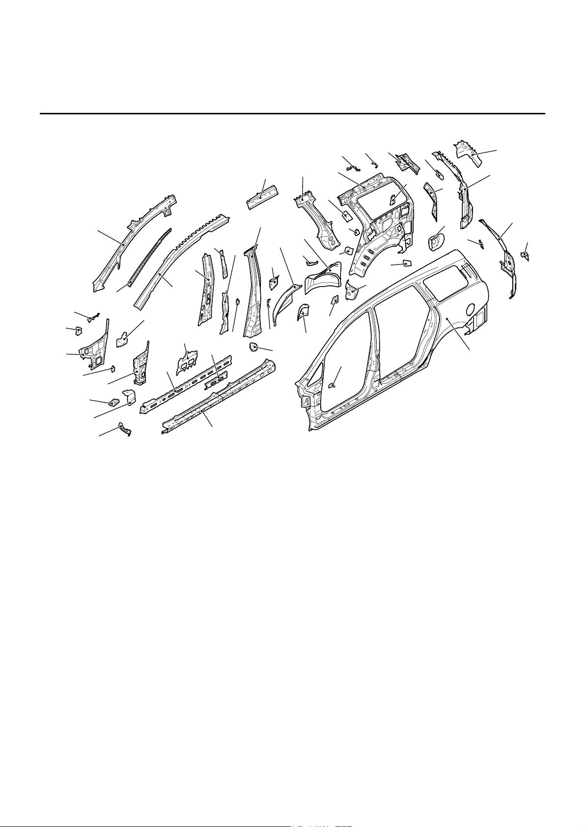
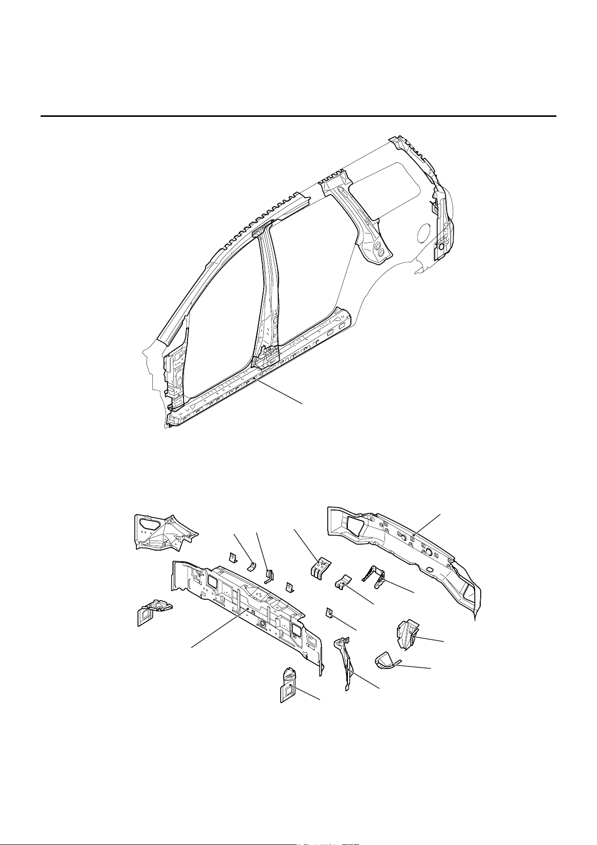
SIDE BODY
M4010011000233
SIDE STRUCTURE
• An uneven thickness steel sheet* in which the
sheet thickness is thicker in the order of the
upper section, rear section, and lower section
was employed for the side outer panel to ensure
safety upon side impact.
• The rear wheel houses each consist of a front
and a rear panel, and thick steel plates are used
for the rear wheel house panels where the rear
suspensions are installed, in order to heighten
the body rigidity and improve driving stability.
NOTE: *: A steel sheet of varying thickness that is
welded into one steel sheet.
AB301685
AB
1
7
11
2
9
8
4
3
6
5
10
1. Dash crossmember upper
2. Dash crossmember reinforcement upper
3. Dash panel plate (RH drive vehicles, A/T lever type)
4. Dash panel
5. Dash crossmember lower
6. Accel pedal upper bracket (LH drive vehicles)
7. Clutch pedal support bracket (Vehicle for M/T)
8. Dash panel reinforcement
9. Clutch pedal stopper bracket (RH drive vehicles,
M/T)
10. Accel pedal bracket (LH drive vehicles)
11. Steering shaft bracket
Page 16
BODY CONSTRUCTION CHARACTERISTICS
BODY CONSTRUCTION
1-13
SIDE STRUCTURE REINFORCEMENT
An uneven thickness steel sheet* in which the sheet
thickness is thicker in the forward part of the vehicle
was employed for the side sill reinforcement to
ensure safety upon side impact.
NOTE: *: A steel sheet of varying thickness that is
welded into one steel sheet.
AB301697
AB
1
2
3
4
5
6
7
8
9
10
12
13
14
15
16
18
19
20
21
22
23
24
25
26
27
28
29
30
31
32
35
36
37
38
39
40
44
34
17
41
42
43
33
46
45
48
51
50
49
11
47
1. Front fender lower bracket
2. Front door hinges reinforcement lower
3. Front pillar reinforcement bulkhead lower
4. Front pillar reinforcement outer lower
5. Front door checker bulkhead
6. Front door hinges reinforcement upper
7. Front pillar inner lower
8. Deck crossmember bracket
9. Instrument panel side bracket
10. Front pillar inner upper
11. Front pillar support (Driver’s side)
12. Front pillar reinforcement outer upper (Passenger’s
side)
13. Centre pillar inner
14. Seat belt anchor reinforcement
15. Rear door hinges reinforcement upper
16. Side roof rail inner
17. Centre pillar reinforcement outer
18. Third seat anchor reinforcement
19. Rear wheel house inner front panel
20. Shock absorber reinforcement
21. Rear wheel house inner rear panel
22. Rear door striker reinforcement
23. Seat belt reinforcement lower second
24. Seat belt reinforcement rear pillar
25. Rear pillar reinforcement outer
26. Quarter inner panel
27. Radio tuner amplifier bracket (Right side)
28. TV tuner amplifier bracket (Left side)
29. Quarter inner extension upper
30. Seat belt reinforcement lower third
31. Seat belt reinforcement upper
32. Quarter inner extension
33. Gate pillar upper reinforcement
34. Gate pillar reinforcement
35. Fuel filler neck bracket (Left side)
36. Gas spring reinforcement
37. Quarter outer extension
38. Tailgate dumper reinforcement side
39. Side outer panel
40. Fender bracket
41. Side sill reinforcement
42. Side sill reinforcement front
43. Seat belt front anchor reinforcement
44. Side sill reinforcement centre
45. Rear door check bulkhead
46. Side sill bulkhead rear
47. Harness bracket
48. Shock absorber support
49. Rear seat belt reinforcement wheel house
50. Shield plate front
51. Shield plate rear
Page 17
BODY CONSTRUCTION CHARACTERISTICS
BODY CONSTRUCTION
1-14
REAR BODY
M4010012000203
REAR END CROSSMEMBER
AB301707
AB
Side sill reinforcement
AB301708
AB
1
2
3
4
5
6
7
8
9
10
11
12
1. Rear end panel inner
2. Heat protector bracket
3. Muffler hanger bracket rear
4. Tailgate striker reinforcement
5. Rear end panel outer
6. Jack rear bulkhead
7. Spare tyre reinforcement rear end
8. Jack rear bracket A
9. Jack rear bracket B
10. Bumper bracket
11. Rear floor side brace
12. Quarter inner extension lower
Page 18
BODY CONSTRUCTION CHARACTERISTICS
BODY CONSTRUCTION
1-15
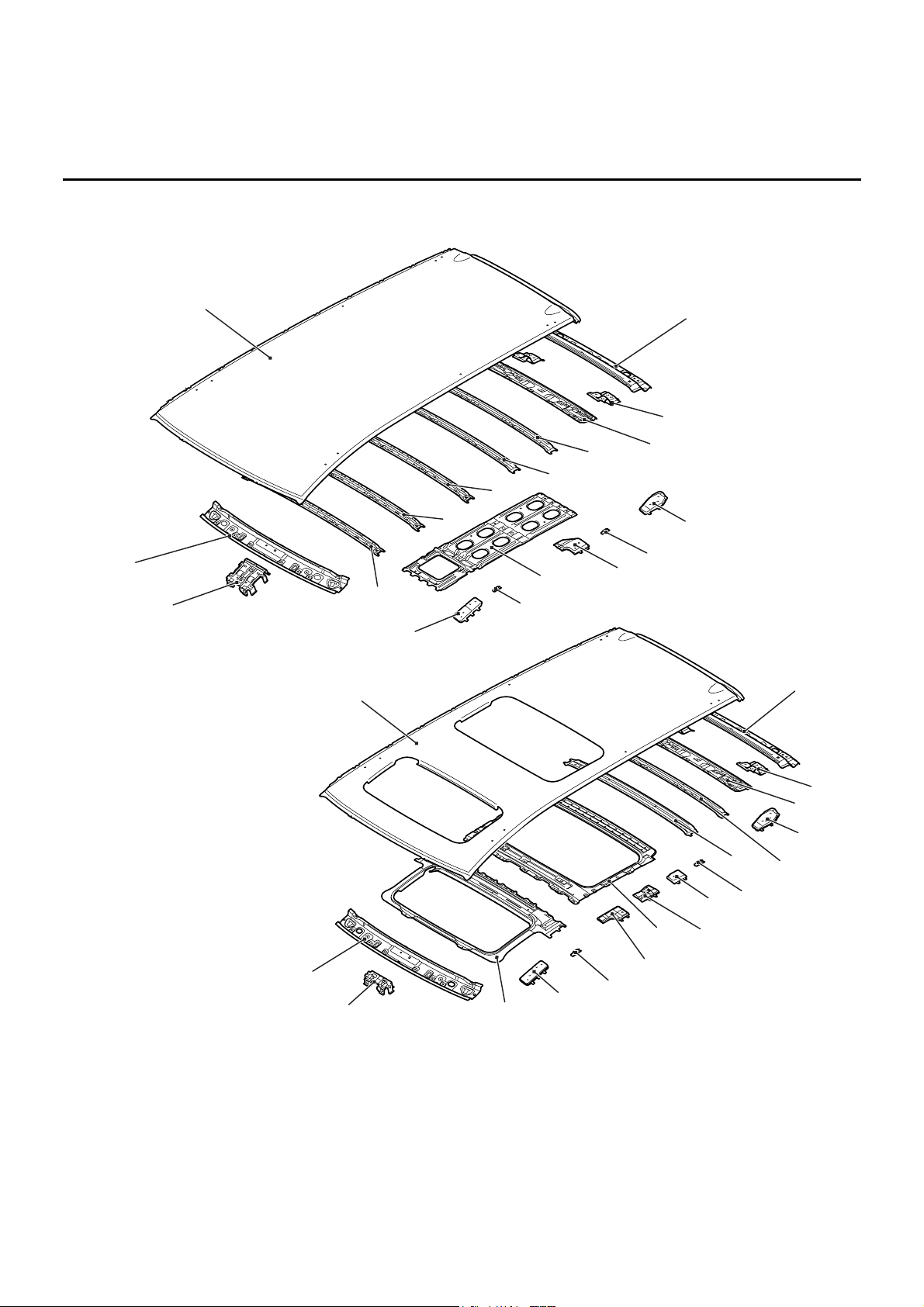
ROOF
M4010013000217
AB300305
AB301710
AB300304
Except for sun roof
Vehicles with sun roof
AB
1
2
3
4
5
6
7
8
9
10
11
12
13
14
15
16
17
2
3
4
5
6
18
19
20
7
11
8
16
15
8
9
8
21
1. Overhead console bracket
2. Front roof rail inner
3. Roof panel
4. Rear roof rail outer
5. Tailgate hinge reinforcement
6. Rear roof rail inner
7. Roof rack reinforcement rear (Vehicles with roof rail)
8. Roof carrier bracket
9. Roof rack reinforcement centre (Vehicles with roof
rail)
10. Roof centre reinforcement
11. Roof rack reinforcement front (Vehicles with roof rail)
12. Roof bow A
13. Roof bow B
14. Roof bow centre
15. Roof bow D
16. Roof bow E
17. Set bracket rear
18. Roof reinforcement rear
19. Set bracket front
20. Roof reinforcement front
21. Room lamp bracket
Page 19
BODY CONSTRUCTION CHARACTERISTICS
BODY CONSTRUCTION
1-16
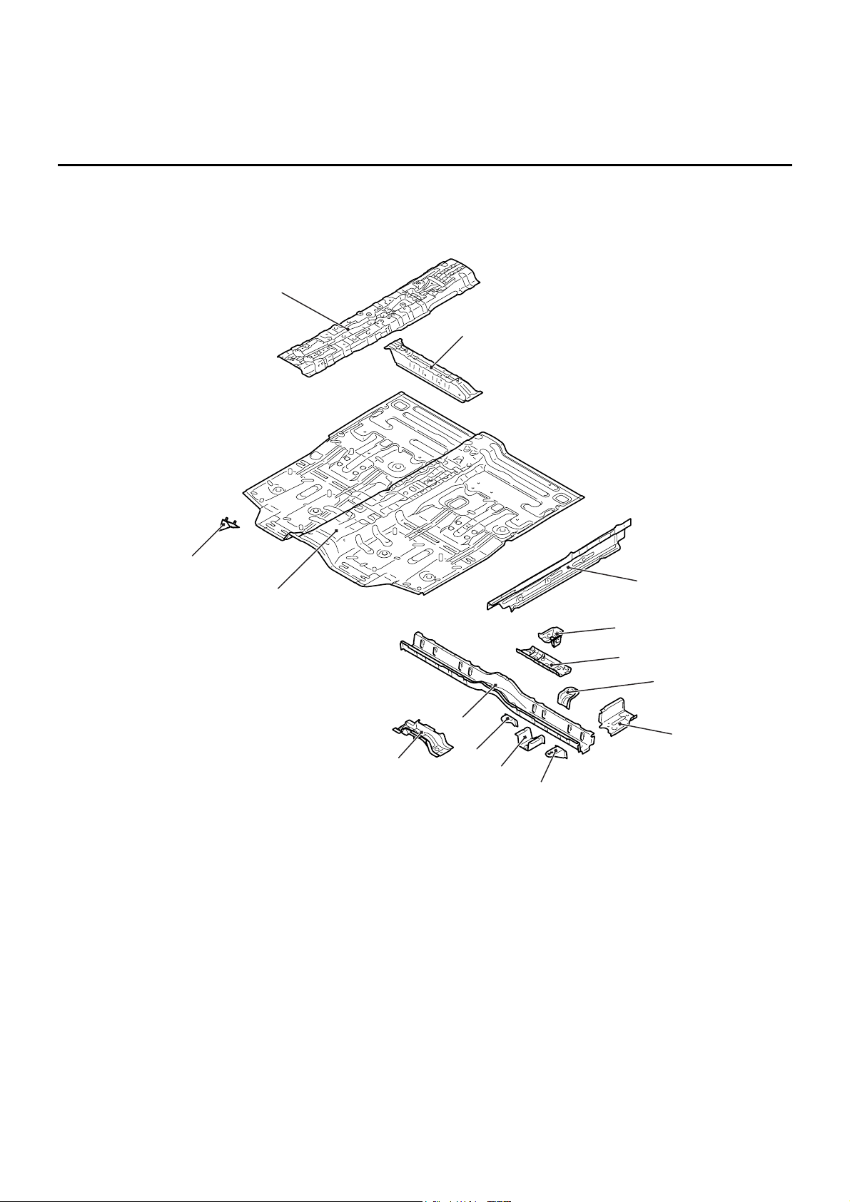
UNDER BODY
M4010014000265
FRONT FLOOR
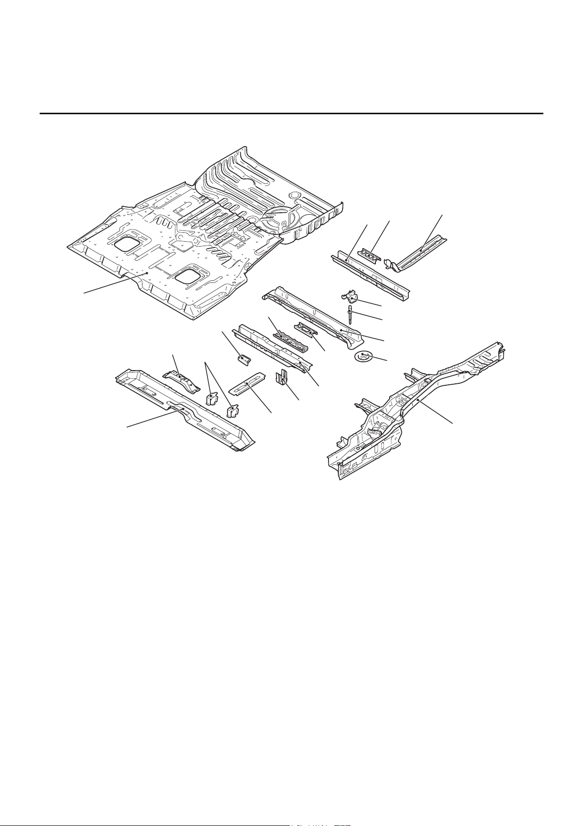
REAR FLOOR
• An uneven thickness steel sheet* in which the
sheet thickness is thicker in the forward part of
the vehicle was employed for the rear floor side
member to ensure safety upon impact.
NOTE: *: A steel sheet of varying thickness that is
welded into one steel sheet.
AB301673
AB
1
2
3
4
5
6
7
8
9
10
11
12
13
14
1. Front floor pan
2. Foot rest bracket (R.H. drive vehicles)
3. Backbone reinforcement
4. Front floor crossmember front
5. Front floor side sill inner
6. Front floor crossmember rear bulkhead
7. Front floor crossmember rear reinforcement
8. Fuel tank support bracket front
9. Front floor sidemember extension rear
10. Front seat reinforcement rear side
11. Front floor sidemember extension front
12. Front seat anchor reinforcement centre
13. Front floor crossmember rear
14 Front floor crossmember front centre
Page 20
BODY CONSTRUCTION CHARACTERISTICS
BODY CONSTRUCTION
1-17
AB301667
AB
1
2
3
4
5
6
7
8
9
10
11
12
13
15
17
18
14
16
1. Rear floor crossmember A
2. Seat anchor reinforcement front centre A
3. Seat anchor front reinforcement
4. Rear floor pan
5. Rear floor crossmember D
6. Seat anchor reinforcement D
7. Seat pan reinforcement
8. Rear suspension crossmember bulkhead
9. Mounting bolt
10. Rear floor crossmember C
11. Spring sheet
12. Seat anchor reinforcement B
13. Rear floor crossmember centre reinforcement B
(Seven-passenger model)
14. Rear floor crossmember B
15. Fuel tank support bracket rear
16. Flange reinforcement (Seven-passenger model)
17. Front stringer
18. Rear floor sidemember
Page 21
BODY CONSTRUCTION CHARACTERISTICS
BODY CONSTRUCTION
1-18
REAR FLOOR SIDEMEMBER
REINFORCEMENT
AB301668
AB
1
2
3
4
5
6
8
9
10
11
12
13
14
15
16
20
21
22
23
25
17
19
24
18
7
AB301675
A
B
AB
12
11
13
2
25
5
7
9
14
20
1. Rear floor sidemember extension front
2. Tie down hook plate
3. Fuel tank support bracket
4. Pipe nut
5. Pipe support front
6. Rear floor crossmember extension B
7. Seat anchor rear reinforcement (Seven-passenger
model right side)
8. Seat anchor rear reinforcement (Except for seven
passenger model right side)
9. Rear floor sidemember front bulkhead
10. Rear floor crossmember extension D
11. Rear floor sidemember reinforcement
12. Third seat anchor reinforcement
13. Rear floor sidemember rear bulkhead (Left side)
14. Rear floor sidemember extension rear
15. Rear floor side pan
16. Muffler hanger bracket rear (Right side)
17. Heat protector bracket (Right side)
18. Spare tyre support (Left side)
19. Shipping bracket (Right side)
20. Rear floor sidemember
21. Brake hose bracket
22. Rear floor side sill inner
23. Jack up side reinforcement
24. Sidemember front bulkhead
25. Rear suspension crossmember stopper bracket
AB300434
A
20
12
11
AC
15
AB300435
B
AC
15
14
13
20
Page 22
BODY CONSTRUCTION CHARACTERISTICS
BODY CONSTRUCTION
1-19
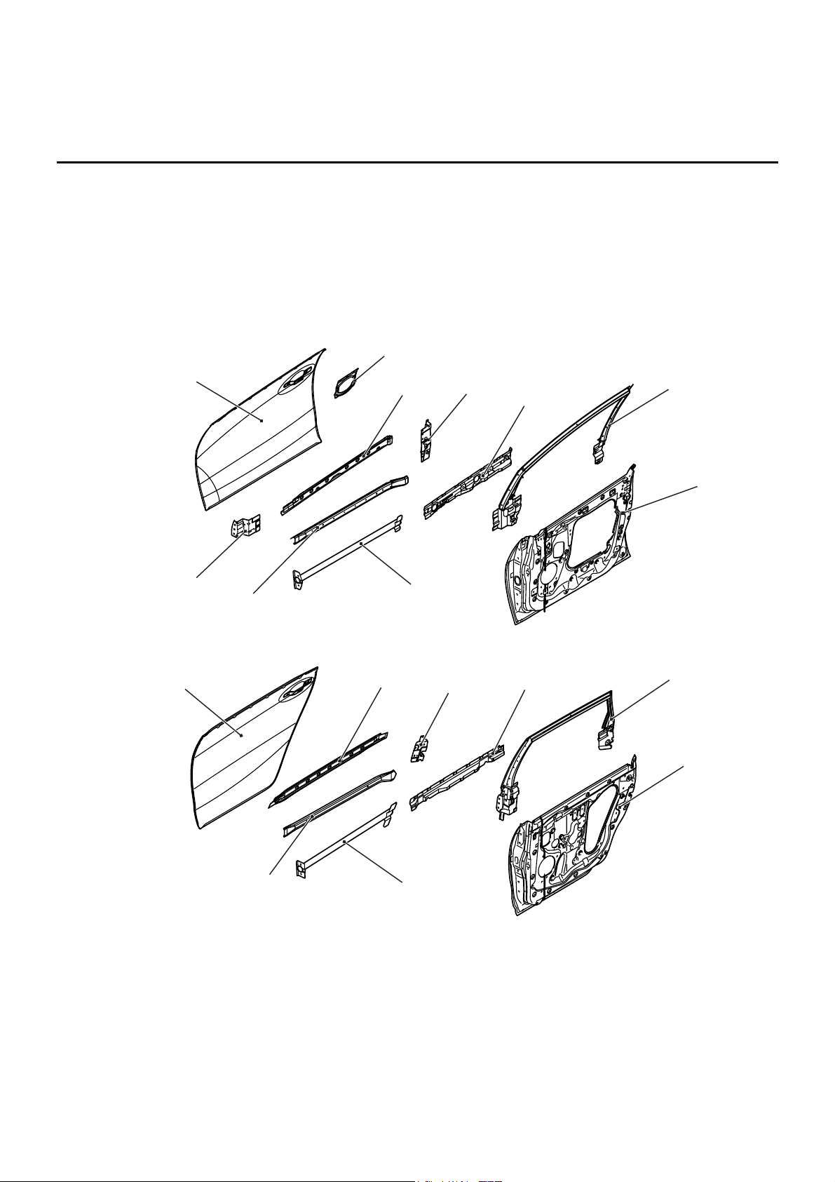
DOOR
M4010015000213
• An uneven thickness steel sheet* in which the
sheet thickness is thicker in the forward part of
the vehicle was employed for the inner panel to
improve rigidity.
• The front and rear side door beam was located in
the bumper position of the vehicle to improve
cabin protection upon side impact.
• A belt line inner reinforcement has been adopted
to improve cabin protection upon impact.
• The bottom section of the door sash pillar was
enlarged and the couplings between the hinge,
latch and door sash were strengthened to
improve sash rigidity.
NOTE: *: A steel sheet of varying thickness that is
welded into one steel sheet.
AB301700
1
2
3
4
5
6
AB
7
8
9
10
Front door
AB301699
AB
Rear door
12
13
14
15
16
17
18
11
1. Front door outer panel
2. Front door outside handle reinforcement
3. Front door belt line outer reinforcement
4. Front door latch reinforcement
5. Front door belt line inner reinforcement
6. Front door window sash
7. Front door inner panel
8. Front side door beam
9. Front door outer stiffener
10. Front door hinge upper reinforcement
11. Rear door outer panel
12. Rear door belt line outer reinforcement
13. Rear door latch reinforcement
14. Rear door belt line inner reinforcement
15. Rear door window sash
16. Rear door inner panel
17. Rear side door beam
18. Rear door outer stiffener
Page 23
SILENCER APPLICATION LOCATIONS
BODY CONSTRUCTION
1-20
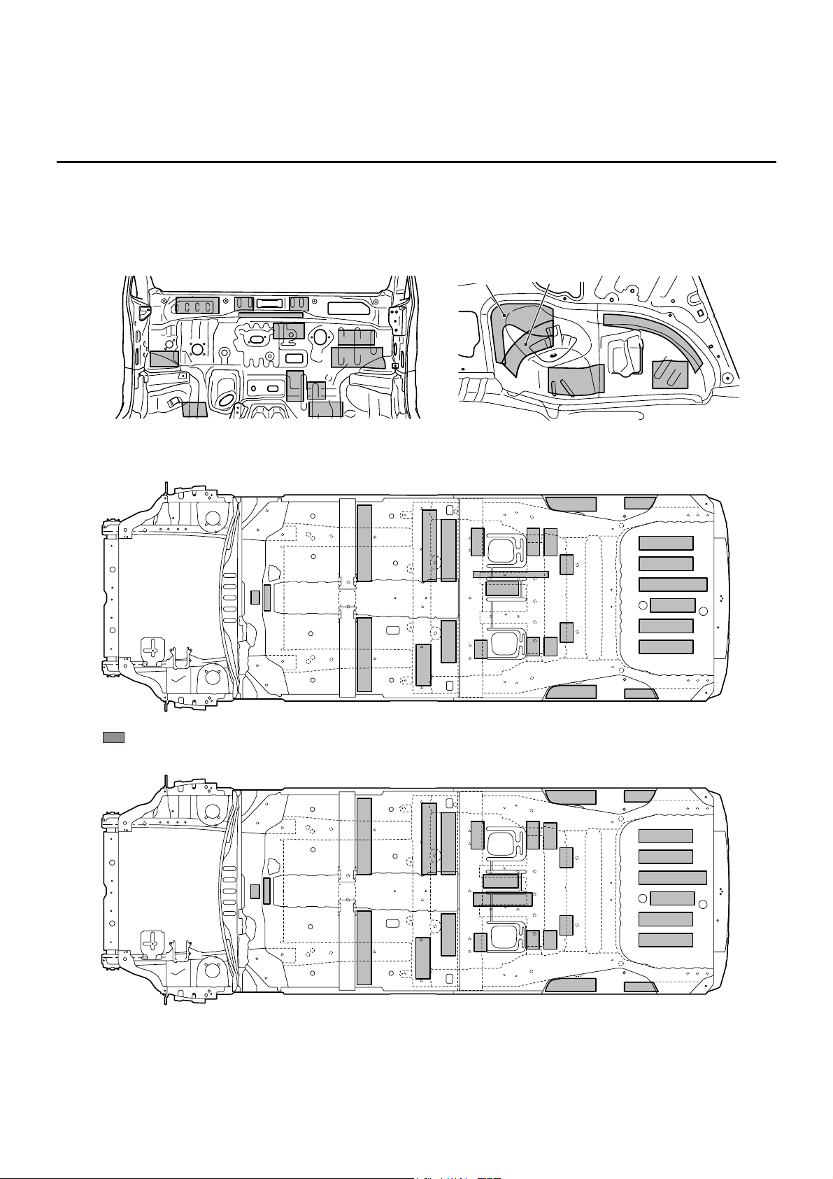
SILENCER APPLICATION LOCATIONS
M4010005000278
Sound insulation was improved by using a
spray-type anti-vibration agent on the cabin side of
the dash panel, rear wheel house and rear floor.
Use a melting sheet for repair.
NOTE: ( ) indicates the number of melting sheets that are used for repair.
AB300368
AB301712
AB
Rear wheel house inner
Dash panel
<Left side>
<Right side>
AB301714
AB
Six-passenger model
: 3.2 mm thick melting sheet and RSS (Place two 1.6 mm melting sheet one on top of another.)
AB301713
AB
Seven-passenger model
Page 24
LOCATIONS USING URETHANE FOAM AND FOAM MATERIAL
BODY CONSTRUCTION
1-21
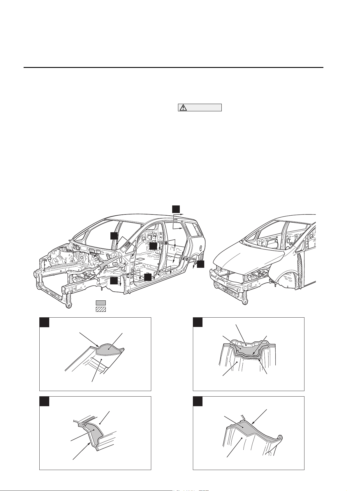
LOCATIONS USING URETHANE FOAM AND FOAM
MATERIAL
M4010007000177
• Introduction of noise was prevented by adding
acoustic foam materials inside the front pillar,
centre pillar, side roof rail and wheel house arch.
• Introduction of noise was prevented by inserting
urethane foam inside the front pillar, centre pillar
and front fender.
CAUTION
The foam materials may burn when heated.
Always observe the following instructions.
• Never use a gas burner or burn the areas
using foam materials.
• When cutting the parts using foam materials,
ensure to use tools (air saw, etc.) that do not
generate fire.
• If there is residual foam materials remaining
on the cut section (body side) then weld after
removing the foam materials from periphery
of the welding area.
AB300554
AB300416
AB300490
AC
A
B
C
E
F
D
: Acoustic foam
: Urethane foam
AB300446
AC
Acoustic foam
material
Side outer panel
Front pillar
inner upper
A
AB300448
AC
B
Acoustic foam
material
Roof side rail inner
Side outer panel
AB300447
AC
Centre pillar
reinforcement outer
Centre pillar inner
Acoustic foam
material
C
Seat belt anchor
reinforcement
Side outer panel
AB300449
AC
Side outer panel
Quarter inner panel
Acoustic foam
material
D
Page 25
STIFFENER AND DAMP SHEET APPLICATION LOCATIONS
BODY CONSTRUCTION
1-22
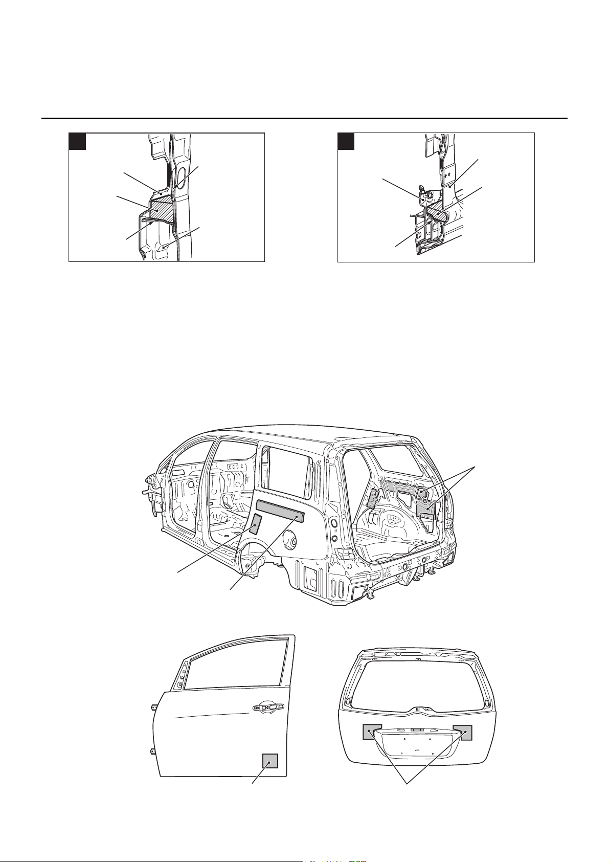
STIFFENER AND DAMP SHEET APPLICATION LOCATIONS
M4010008000192
Sound insulation was improved with anti-vibration
effects and heightening surface rigidity with a
stiffener on the inner side of the side outer panel and
the tailgate outer panel, as well as a damping sheet
adhered to the inner side of the front door and the
rear door outer panel.
NOTE: The main contents of a stiffener are epoxy
resin. It comes in a sheet form and contains a
mixture of glass fibre and filler, and cures (stiffens)
when heated. It is used to improve the rigidity of the
outer plate.
AB300450
AC
Urethane foam
Front pillar
reinforcement
outer lower
Front pillar inner lower
Front door hinge
reinforcement
lower
Front floor side
sill inner front
E
AB300451
AC
Side outer panel
Urethane
foam
Side sill
reinforcement
Seat belt front
anchor reinforcement
F
AB301882
AB
Stiffener
Stiffener
Damp sheet
AB301881
AB
Stiffener
Damp sheet
Front door
Tailgate
Page 26

2-1
GROUP 2
BODY DIMENSIONS
CONTENTS
BODY DIMENSIONS AND MEASUREMENT
METHODS . . . . . . . . . . . . . . . . . . . . . 2-2
TYPE A (PROJECTED DIMENSIONS)
. . . . . . . . . . . . . . . . . . . . . . . . . . . . . . . . . 2-3
UNDER BODY . . . . . . . . . . . . . . . . . . . . . . 2-3
SUSPENSION INSTALLATION DIMENSIONS
. . . . . . . . . . . . . . . . . . . . . . . . . . . . . . . . . . . . . . 2-5
TYPE B (ACTUAL-MEASUREMENT
DIMENSIONS). . . . . . . . . . . . . . . . . . . 2-7
UNDER BODY. . . . . . . . . . . . . . . . . . . . . . . 2-7
SUSPENSION INSTALLATION DIMENSIONS
. . . . . . . . . . . . . . . . . . . . . . . . . . . . . . . . . . . . . . 2-8
FRONT BODY . . . . . . . . . . . . . . . . . . . . . . . 2-10
SIDE BODY . . . . . . . . . . . . . . . . . . . . . . . . . 2-12
REAR BODY . . . . . . . . . . . . . . . . . . . . . . . . 2-13
INTERIOR . . . . . . . . . . . . . . . . . . . . . . . . . . 2-14
Page 27
BODY DIMENSIONS AND MEASUREMENT METHODS
BODY DIMENSIONS
2-2
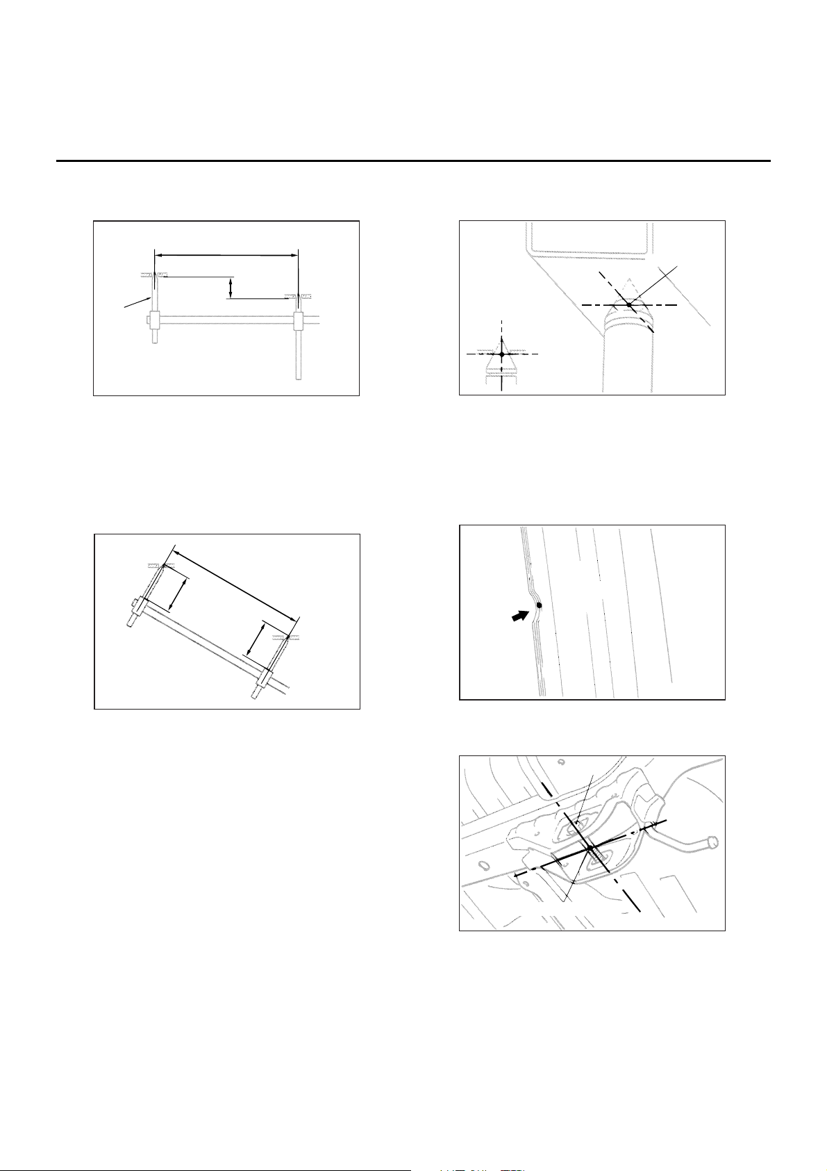
BODY DIMENSIONS AND MEASUREMENT METHODS
M4020001000255
1. Type A (projected dimensions)
Indicates the dimension when a measurement
location is projected onto the plane.
The difference in height of the measurement
points should be taken into consideration when
measuring.
2. Type B (actual-measurement dimensions)
Indicates the actual distance between the
measurement points.
Measure using a tracking gauge or a measuring
tape, etc.
NOTE: .
•
Make the lengths of the tracking gauge probes
the same (A=A’).
•
Do not bend or twist the measuring tape.
3. Insert the tracking gauge probes securely into the
measurement holes.
4. When the standard dimensions in the illustration
are enclosed by rectangle, this indicates that the
symmetrical left and right positions have the same
dimensions.
5. When using a notch for dimension measurement,
set the measuring point at the centre of the notch.
6. When measuring the suspension mounting arm,
or link mounting position, use the suspension
mounting bolt, etc. (Type B only)
7. The body centre points are shown for the purpose
of checking the position of the left and right
symmetry location.
AB100778
Projected dimension
Height
Probe
AB
AB100779
AB
Actual-measured dimension
A
A'
AB100780
AD
Centre of hole
AB100781
AB
AB100782
AB
Bolt
Measurement point
Page 28
TYPE A (PROJECTED DIMENSIONS)
BODY DIMENSIONS
2-3
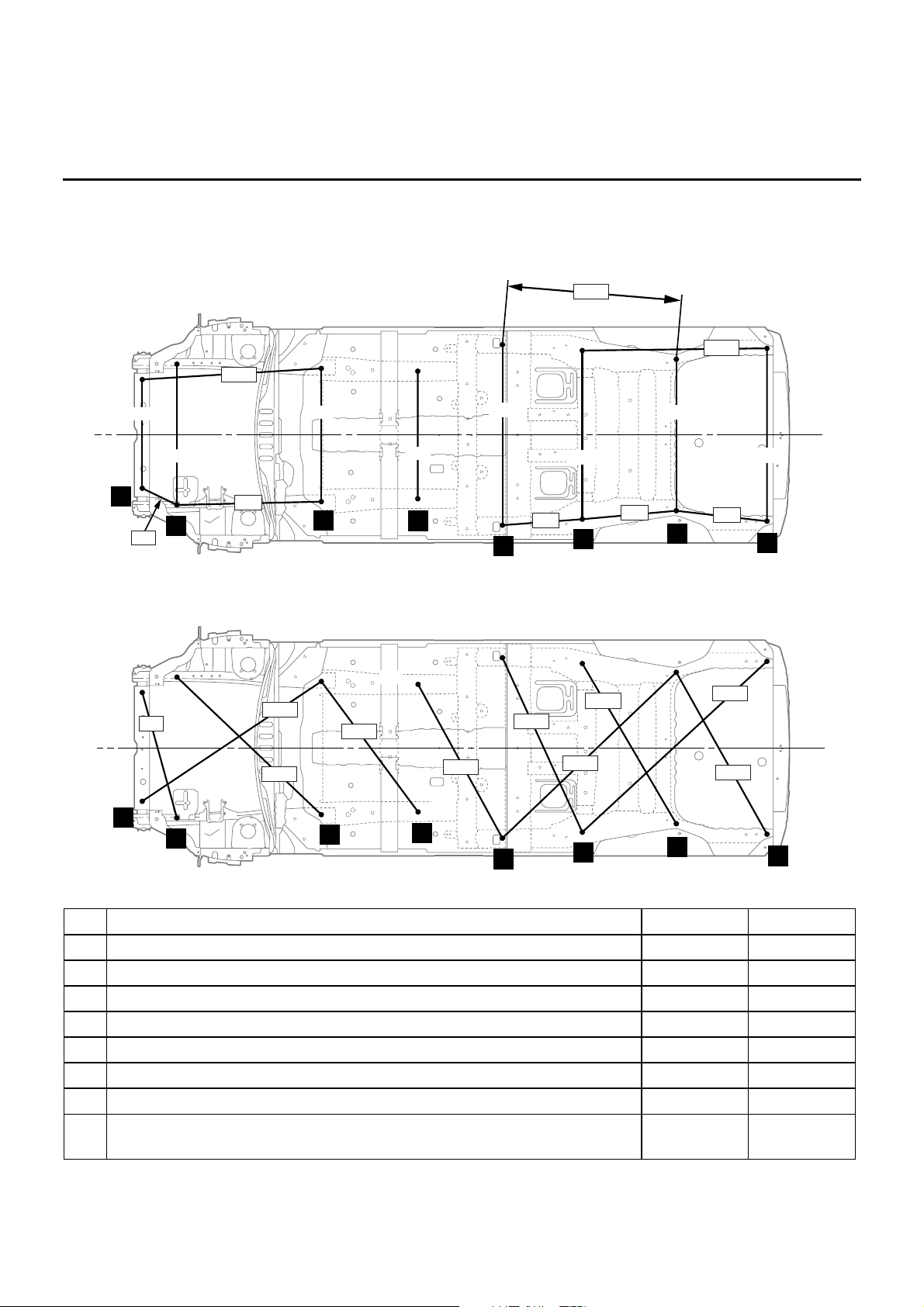
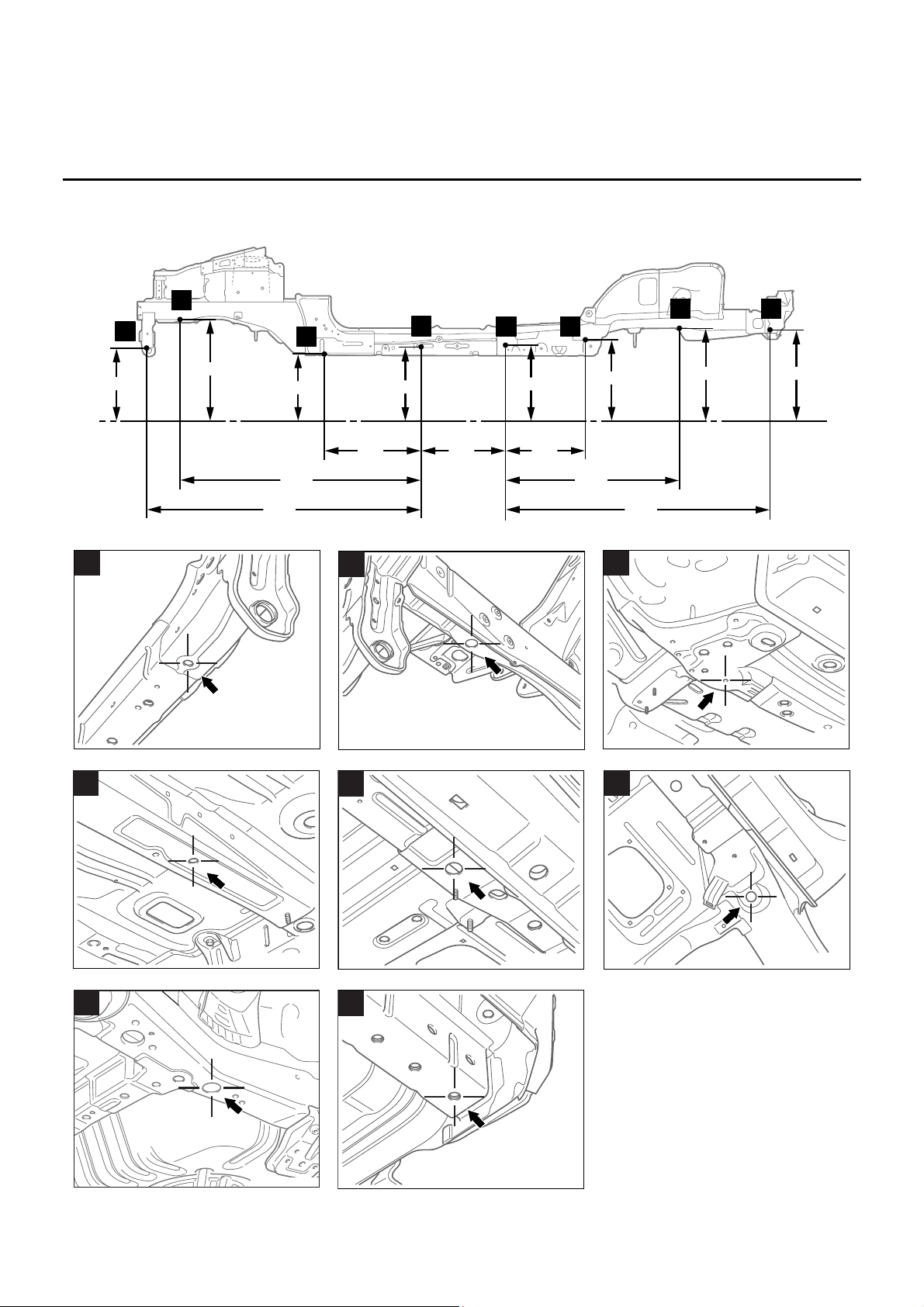
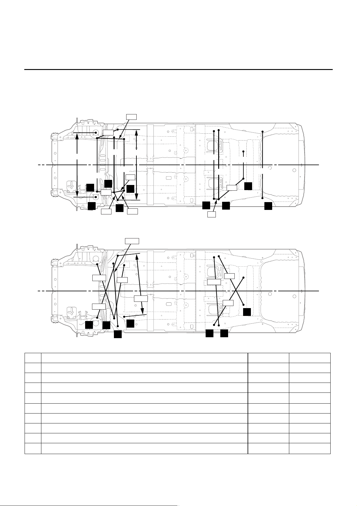
TYPE A (PROJECTED DIMENSIONS)
UNDER BODY
M4020005000536
NOTE: The * mark indicates the mounting position for the frame centring gauge.
AB301815
AB
2
1
5
3
4
7
6
8
740
960
908
979
271
870
1200
558
642
628
1261
1230
1240
1160
1030
1180
mm
AB301816
AB
2
1
5
3
4
7
6
8
885
1478
1353
1323
1268
1648
1721
1269
1117
1216
No. Standard measurement point Hole shape Size mm
1* Centre of front end crossmember brace positioning hole Round 12
2* Centre of front sidemember inner positioning hole Round 25
3* Centre of suspension crossmember stay mounting hole Round 14
4* Centre of front floor sidemember positioning hole Round 16
5* Centre of rear floor sidemember extension front positioning hole Round 25
6* Centre of rear floor sidemember water draining hole Round 25
7* Centre of rear floor sidemember positioning hole Round 35
8* Centre of hichmember mounting hole (This hole also serves as a
shipping bracket mounting hole on left side.)
Round 16
Page 29
TYPE A (PROJECTED DIMENSIONS)
BODY DIMENSIONS
2-4
AB301817
1195
676
128
330
100
150
165
219
282 269
605 557
1655
1903
1818
AB
2
1
5
3
4
7
6
8
mm
AB300200
AB
1
AB300201
AB
2
AB300195
AB
3
AB300196
AB
4
AB300197
AB
5
AB300194
AB
6
AB301814AB301814
AB
7
AB300199
AB
8
Page 30
TYPE A (PROJECTED DIMENSIONS)
BODY DIMENSIONS
2-5
SUSPENSION INSTALLATION
DIMENSIONS
M4020013000467
AB301820
AB
9
12
11
392
297
181
206
154
940
908
970
1250
474
89
574
480
1192
1230
13
3
14
15
16
mm
10
1145
1165
AB301821
AB
12
11
13
3
14
15
16
1000
1153
1085
1112
1214
959
985
956
No. Standard measurement point Hole shape Size mm
3 Centre of suspension crossmember stay mounting hole Round 14
9 Centre of front shock absorber mounting hole Round 104.6
10 Centre of rear shock absorber mounting hole Round 22
11 Tip of front suspension crossmember mounting bolt
−−
12 Centre of suspension crossmember positioning hole Round 15.5
13 Centre of suspension crossmember stay mounting hole Round 16
14 Centre of rear suspension stopper front mounting hole Round 11
15 Centre of rear suspension crossmember mounting hole Round 15.5
16 Tip of rear suspension crossmember mounting bolt
−−
Page 31

TYPE A (PROJECTED DIMENSIONS)
BODY DIMENSIONS
2-6
AB300297
AB300220
AB300221
AB
A
Centre of vehicle
AB
B
Centre of vehicle
AB
500
mm
750
183 106 106 100 123 200 149
864
87
521
114
178
474
1639
546
9
12
11
13
3
14
15
16
10
A
B
7˚54´
7˚36´
1˚42´
13˚18´
AB300632
AB
12
13
3
3, 12, 13
AB202307
AB
9
AB300202
AB
10
Page 32

TYPE B (ACTUAL-MEASUREMENT DIMENSIONS)
BODY DIMENSIONS
2-7
TYPE B (ACTUAL-MEASUREMENT DIMENSIONS)
UNDER BODY
M4020005000547
AB301818
AB
2
1
5
3
4
7
6
8
740 960
908
338
1205
561
645
628
1262
1230
1240 1160 1030
1180
mm
1006
870
AB301819
AB
2
1
5
3
4
7
6
8
908
1478
1373
1324
1269
1652
1721
1269
1118
1216
No. Standard measurement point Hole shape Size mm
1 Centre of front end crossmember brace positioning hole Round 12
2 Centre of front sidemember inner positioning hole Round 25
3 Centre of suspension crossmember stay mounting hole Round 14
4 Centre of front floor sidemember positioning hole Round 16
5 Centre of rear floor sidemember extension front positioning hole Round 25
6 Centre of rear floor sidemember water draining hole Round 25
7 Centre of rear floor sidemember positioning hole Round 35
8 Centre of hichmember mounting hole (This hole also serves as a
shipping bracket mounting hole on left side.)
Round 16
Page 33

TYPE B (ACTUAL-MEASUREMENT DIMENSIONS)
BODY DIMENSIONS
2-8
SUSPENSION INSTALLATION
DIMENSIONS
M4020013000478
AB300200
AB
1
AB300201
AB
2
AB300195
AB
3
AB300196
AB
4
AB300197
AB
5
AB300194
AB
6
AB301814AB301814
AB
7
AB300199
AB
8
AB301820
AC
12
11
400
306
181
206
154
940
908
970
1250
482
117
576
480
1192
1230
13
3
14
15
16
mm
Page 34

TYPE B (ACTUAL-MEASUREMENT DIMENSIONS)
BODY DIMENSIONS
2-9
AB301821
AC
12
11
13
3
14
15
16
1003
1155
1085
1112
1217
960
985
956
No. Standard measurement point Hole shape Size mm
3 Centre of suspension crossmember stay mounting hole Round 14
11 Tip of front suspension crossmember mounting bolt
−−
12 Centre of suspension crossmember positioning hole Round 15.5
13 Centre of suspension crossmember stay mounting hole Round 16
14 Centre of rear suspension stopper front mounting hole Round 11
15 Centre of rear suspension crossmember mounting hole Round 15.5
16 Tip of rear suspension crossmember mounting bolt
−−
AB300632
AB
12
13
3
3, 12, 13
AB300205
AB
11
AB300593
AB
14
15
14, 15
AB300206
AB
16
Page 35

TYPE B (ACTUAL-MEASUREMENT DIMENSIONS)
BODY DIMENSIONS
2-10
FRONT BODY
M4020006000261
AB301825
Body centre point
768
Body centre point
524
277
1010
1176
1046
1683
1478
763
770
822
1439
1011
1583
1577
931
927
1001
710
1528
1535
874
863
783
159
353
505
392
653
453
17
18
19
20
19
20
17
21
22
23
24
25
26
27
28
29
21
23
24
25
26
28
937
1000
20
21
23
24
25
27
874
467
468
413
1191
1198
22
409
969
1403
981
974
AB
mm
Page 36

TYPE B (ACTUAL-MEASUREMENT DIMENSIONS)
BODY DIMENSIONS
2-11
No. Standard measurement point Hole shape Size mm
17 Centre of dynamic damper mounting hole Round 11
18 Centre of hood lock stay mounting hole Round 9
19 Centre of front end beam mounting hole Round 13
20 Centre of front end beam mounting hole Round 13
21 Centre of front end beam mounting hole Round 13
22 Centre of front end upper bar mounting hole Round 6.6
23 Centre of front end upper bar mounting hole Round 10
24 Centre of front end upper bar side positioning hole Round 8
25 Centre of front end upper bar side positioning hole Round 8
26 Centre of cowl top front panel mounting hole (Body centre point) Round 6.6
27 Centre of front strut mounting hole Round 11.5
28 Centre of hood hinge mounting hole Round 9
29 Corner of roof panel
−−
AB300337
AB
19
17
18
17, 18, 19
AB202310
20
AB
23
22
20, 22, 23
AB300333
AB
21
AB202305
AB
24
AB300328
AB
25
AB301829
AB
26
AB202306
AB
28
27
27, 28
AB300247
AB
29
Page 37

TYPE B (ACTUAL-MEASUREMENT DIMENSIONS)
BODY DIMENSIONS
2-12
SIDE BODY
M4020007000264
AB300224
AB
mm
30
31
32
33
35
34
36
37
38
39
619
608
1142
1180
1138
1018
1051
1244
930
624
749
832
848
AB300225
AB
41
40
32
43
42
46
44
852
370
410
940
990
1135
1109
1192
1109
1059
No. Standard measurement point Hole shape Size mm
30 Front pillar positioning notch (upper)
−−
31 Front pillar positioning notch (lower)
−−
32 Side roof rail positioning notch (front)
−−
33 Side sill positioning notch (front)
−−
34 Centre pillar positioning notch (upper)
−−
35 Centre pillar positioning notch (lower)
−−
36 Side roof rail positioning notch (rear)
−−
37 Side sill positioning notch (rear)
−−
38 Quarter panel positioning notch (upper)
−−
39 Quarter panel positioning notch (lower)
−−
40 Centre of front door hinge mounting hole (upper) Round 11
41 Centre of front door hinge mounting hole (lower) Round 11
42 Centre of front door hinge mounting hole (lower) Round 11
43 Centre of rear door hinge mounting hole (lower) Round 12
44 Centre of rear door switch mounting hole Round 5
Page 38

TYPE B (ACTUAL-MEASUREMENT DIMENSIONS)
BODY DIMENSIONS
2-13
REAR BODY
M4020008000278
AB300596
AB
41
40
31
31, 40, 41
AB300235
AB
43
35
35, 43
AB300250
AB
44
39
39, 44
AB300231
mm
730
1266
900
562
1206
792
765
1122
1323
1045
579
1021
1033
AB
45
46
48
47
No. Standard measurement point Hole shape Size mm
45 Centre of tailgate hinge mounting hole Round 11
46 Centre of gas spring mounting hole Round 11
47 Centre of tailgate striker mounting hole Oblong 11×14
48 Centre of rear bumper mounting hole Square 9
AB300251
AB
45
AB300252
AB
46
AB300338
AB
47
48
47, 48
Page 39

TYPE B (ACTUAL-MEASUREMENT DIMENSIONS)
BODY DIMENSIONS
2-14
INTERIOR
M4020009000282
AB300227
mm
1308
1217
1382
1203
1336
1484
1484
1484
1484
1472
AB
31
30
32
34
35
37
39
38
36
33
AB300228
1280
973
774
810
1323
1242
1186
1462
1349
1131
AB
30
31
32
33
34
35
37
36
38
39
49
Body centre point
AB300232
50
51
10
995
736
711
1165
1168
AB
Body centre point
Page 40

TYPE B (ACTUAL-MEASUREMENT DIMENSIONS)
BODY DIMENSIONS
2-15
No. Standard measurement point Hole shape Size mm
10 Centre of rear shock absorber mounting hole Round 22
30 Front pillar positioning notch (upper)
−−
31 Front pillar positioning notch (lower)
−−
32 Side roof rail positioning notch (front)
−−
33 Side sill positioning notch (front)
−−
34 Centre pillar positioning notch (upper)
−−
35 Centre pillar positioning notch (lower)
−−
36 Side roof rail positioning notch (rear)
−−
37 Side sill positioning notch (rear)
−−
38 Quarter panel positioning notch (upper)
−−
39 Quarter panel positioning notch (lower)
−−
49 Centre of parking brake cable bracket mounting hole (Body centre point) Round 9
50 Body centre point of rear floor
−−
51 Centre of rear end trim mounting hole Round 8.5
AB300595
AB
10
AB300597
AB
31
AB300598
AB
35
AB300259
AB
49
AB300256
AB
50
AB300258
51
AB
Page 41

TYPE B (ACTUAL-MEASUREMENT DIMENSIONS)
BODY DIMENSIONS
2-16
AB300260
AB301813
AB
52
54
55
53
(L.H. drive vehicles)
100
151
1435
1437
1439
1444
AB300260
AD
56
57
58
59
100
151
1435
1437
1439
1444
(R.H. drive vehicles)
No. Standard measurement point Hole shape Size mm
52 Centre of deck crossmember mounting hole (left-upper) Round 11
53 Centre of deck crossmember mounting hole (left-lower) Round 11
54 Centre of deck crossmember mounting hole (right-upper) Round 9
55 Centre of deck crossmember mounting hole (right-lower) Round 9
56 Centre of deck crossmember mounting hole (left-upper) Round 9
57 Centre of deck crossmember mounting hole (left-lower) Round 9
58 Centre of deck crossmember mounting hole (right-upper) Round 11
59 Centre of deck crossmember mounting hole (right-lower) Round 11
AB301826
52
53
AB
52, 53
AB301827
54
55
AB
54, 55
AB300261
56
57
AB
56, 57
Page 42

TYPE B (ACTUAL-MEASUREMENT DIMENSIONS)
BODY DIMENSIONS
2-17
AB300262
58
59
AB
58, 59
Page 43

3-1
GROUP 3
WELDED PANEL
REPLACEMENT
CONTENTS
HEADLAMP SUPPORT . . . . . . . . . . . 3-2
FENDER SHIELD. . . . . . . . . . . . . . . . 3-2
FRONT SIDEMEMBER (PARTIAL
REPLACEMENT) . . . . . . . . . . . . . . . . 3-6
FRONT PILLAR (DRIVERS SIDE). . . 3-7
FRONT PILLAR (PASSENGERS SIDE)
. . . . . . . . . . . . . . . . . . . . . . . . . . . . . . . . . 3-11
CENTRE PILLAR . . . . . . . . . . . . . . . . 3-15
SIDE SILL . . . . . . . . . . . . . . . . . . . . . . 3-19
QUARTER OUTER . . . . . . . . . . . . . . . 3-21
ROOF . . . . . . . . . . . . . . . . . . . . . . . . . 3-23
REAR FLOOR. . . . . . . . . . . . . . . . . . . 3-25
REAR END PANEL. . . . . . . . . . . . . . . 3-27
QUARTER, INNER . . . . . . . . . . . . . . . 3-29
FRONT DOOR OUTER PANEL . . . . . 3-33
REAR DOOR OUTER PANEL . . . . . . 3-34
Page 44

HEADLAMP SUPPORT
WELDED PANEL REPLACEMENT
3-2
HEADLAMP SUPPORT
M4030003000274
FENDER SHIELD
M4030004000307
AB300463
AB
Spot welding
MIG plug welding : indicates two panels to be welded
: indicates three panels to be welded
MIG spot welding
MIG arc welding (continuous)
Braze welding
Anti-corrosion agent application locations
(Use access holes to apply liberally to butt-welded joints.)
( )
Symbol
Operation description
AB300525
A
AB
A
Right side
REPAIR WELDS
AB300475
AB
Spot welding
MIG plug welding : indicates two panels to be welded
: indicates three panels to be welded
MIG spot welding
MIG arc welding (continuous)
Braze welding
Anti-corrosion agent application locations
(Use access holes to apply liberally to butt-welded joints.)
( )
Symbol
Operation description
Page 45

FENDER SHIELD
WELDED PANEL REPLACEMENT
3-3
NOTE: .
•
Refer to the Headlamp Support Section on P.3-2
for the welding point with headlamp support.
AB302007
AB301896
AB300306
AB301898
AB300307
A
AB
A
G
REPAIR WELDS
(R. H. Drive vehicles)
(R. H. Drive vehicles)
Page 46

FENDER SHIELD
WELDED PANEL REPLACEMENT
3-4
AB302008
AB300313
AB300395
AB301899
AB300309
AB301897
AB300308
E
B
B
C
AB
C
D
(R. H. Drive vehicles)
(R. H. Drive vehicles)
H
D
F
Page 47

FENDER SHIELD
WELDED PANEL REPLACEMENT
3-5
NOTE ON REPAIR WORK
REMOVAL
The welding point between front sidemember inner
and dash panel extension is hidden by the dash
crossmember extension upper. Therefore, when
removing the front sidemember, remove the dash
crossmember extension upper in advance.
INSTALLATION
1. Remove the front sidemember brace lower,
suspension crossmember bracket rear and dash
crossmember extension lower from the new front
sidemember.
2. Remove the dash crossmember extension upper
from the new front sidemember and install the
front sidemember, and then install the dash
crossmember extension upper.
AB302016
AB300312
AB300314
AB300310
AB300311
AB
E
F
H
G
(With the front upper frame extension outer removed)
AB302030
AB
Dash crossmember
extension upper
AB302029
AB
Dash crossmember
extension upper
Front sidemember
Page 48

FRONT SIDEMEMBER (PARTIAL REPLACEMENT)
WELDED PANEL REPLACEMENT
3-6
FRONT SIDEMEMBER (PARTIAL REPLACEMENT)
M4030000100175
NOTE: Refer to the Headlamp Support Section on
P.3-2 for the welding point with headlamp support.
NOTE ON REPAIR WORK
REMOVAL
To reinforce the strength of the front sidemember cut
area, cut the front sidemember outer 50 mm behind
the cut-out part.
AB300507
AB
Spot welding
MIG plug welding : indicates two panels to be welded
: indicates three panels to be welded
MIG spot welding
MIG arc welding (continuous)
Braze welding
Anti-corrosion agent application locations
(Use access holes to apply liberally to butt-welded joints.)
( )
Symbol
Operation description
AB300511
AB
A
85 mm (Right side)
105 mm (Left side)
A
Centre of front sidemember
inner positioning hole
REPAIR WELDS
AB300491
AB
50 mm
Front sidemember outer
Page 49

FRONT PILLAR (DRIVERS SIDE)
WELDED PANEL REPLACEMENT
3-7
FRONT PILLAR (DRIVERS SIDE)
M4030005300011
AB300474
AB
Spot welding
MIG plug welding : indicates two panels to be welded
: indicates three panels to be welded
MIG spot welding
MIG arc welding (continuous)
Braze welding
Anti-corrosion agent application locations
(Use access holes to apply liberally to butt-welded joints.)
( )
Symbol
Operation description
AB301982
AB300392
AB300393
AB300427
AB300426
B
A
C
A
C
B
120 ± 10 mm
115 ± 10 mm
AB
E
F
D
REPAIR WELDS
Foam acoustic
material
(With the front upper frame extension outer removed)
Page 50

FRONT PILLAR (DRIVERS SIDE)
WELDED PANEL REPLACEMENT
3-8
CAUTION
When repairing the area using foam materials do not use firing tools since the foaming materials may
burn.
NOTE: .
•
Refer to the Fender Shield Section on P.3-2 for
the welding point with front upper frame
extension outer.
NOTE ON REPAIR WORK
AB301984
AB300394
AB300424
AB300425
AB
D
E
F
(With the side sill outer reinforcement removed)
Page 51

FRONT PILLAR (DRIVERS SIDE)
WELDED PANEL REPLACEMENT
3-9
INSTALLATION
1. To reinforce the strength of the front pillar cut
area, cut the side outer panel 100 mm above the
cut-out part and front pillar reinforcement outer
upper 50 mm above the cut-out part.
2. To reinforce the strength of the side sill cut area,
cut the side outer panel 100 mm behind the
cut-out part and the side sill reinforcement 50 mm
behind the cut-out part.
3. Cut the new front pillar inner upper by aligning it
with the body side, and then assemble it with the
new front pillar inner lower and install it to the
body. After that, install the front floor side sill inner
front.
CAUTION
Weld and repair if the front pillar support is
damaged.
4. Cut the new front pillar reinforcement outer upper
and the front pillar support by aligning them with
the front pillar reinforcement outer upper of the
body side. Next, cut only the front pillar
reinforcement outer upper 100 mm downwards
from the cut area to create a cover, and then cut
the front pillar support 50 mm above the cut area.
5. To install the front pillar reinforcement outer upper,
weld the front pillar support, and then weld the
cover of front pillar reinforcement outer upper.
6. To prevent the foam materials dripping in filling
them, apply urethane in the area shown in the
figure to bury the inside of the front pillar.
AB301996
AB
Front pillar
reinforcement
outer upper
Side outer
panel
100 mm
50 mm
AB300381
AB
50 mm
100 mm
Side outer panel
Side sill
reinforcement
AB301997
AB
100 mm
Front pillar
reinforcement
outer upper
Front pillar
support
50 mm
Cover
AB301998
AB
Cover
Front pillar
support
AB300383
AB
Urethane
Page 52

FRONT PILLAR (DRIVERS SIDE)
WELDED PANEL REPLACEMENT
3-10
CAUTION
Weld and repair if the side sill reinforcement front
is damaged.
7. Cut the new side sill reinforcement and the side
sill reinforcement front by aligning them with the
cut area of side sill reinforcement in the body side.
Next, cut only the side sill reinforcement 100 mm
forwards from the cut area to create a cover, and
then cut the side sill reinforcement front 50 mm
backwards from the cut area.
8. To install the side sill reinforcement, weld the side
sill reinforcement front, and then weld the cover of
side sill reinforcement.
9. When assembling the new front pillar outer
reinforcement lower, apply structural adhesives in
the areas shown in the figure.
Adhesive: Epoxyayresin adhesive
Brand: 3M ATD Part No.8115 or equivalent
10.When assembling the new front pillar outer, apply
body sealant in the areas shown in the figure of
body side.
AB300384
AB
50 mm
100 mm
Side sill
reinforcement
Cover
Side sill
reinforcement
front
AB300385
AB
Cover
Side sill
reinforcement front
AB300386
AB
: Adhesive
AB302110
AB
: Body sealant
AB300389
AB
Page 53

FRONT PILLAR (PASSENGERS SIDE)
WELDED PANEL REPLACEMENT
3-11
11.Assemble the front pillar outer, then bolt and tape
the hole and flange with aluminium tape and fill
the hole with foam materials as shown in the
figure of the instructions.
FOAM: 3M ATD ULTRAPRO Panel
foam-Yellow
12.Wait 2 hours after filling the foam materials to
remove the bolt and aluminium tape, then melt the
foam materials with a soldering gun so a clip, etc.
can thoroughly be inserted in the hole filled with
foam materials.
FRONT PILLAR (PASSENGERS SIDE)
M4030005400018
AB200418
AB300652
AB
Spot welding
MIG plug welding : indicates two panels to be welded
: indicates three panels to be welded
MIG spot welding
MIG arc welding (continuous)
Braze welding
Anti-corrosion agent application locations
(Use access holes to apply liberally to butt-welded joints.)
( )
Symbol
Operation description
Page 54

FRONT PILLAR (PASSENGERS SIDE)
WELDED PANEL REPLACEMENT
3-12
CAUTION
When repairing the area using foam materials do
not use firing tools since the foaming materials
may burn.
NOTE: .
•
Refer to the Fender Shield Section on P.3-2 for
the welding point with front upper frame
extension outer.
AB301983
AB300392
AB300427
AB300426
AB300393
AB
D
B
F
E
A
B
C
A
C
115 ± 10 mm
120 ± 10 mm
REPAIR WELDS
Foam acoustic
material
(With the front upper frame extension outer removed)
Page 55

FRONT PILLAR (PASSENGERS SIDE)
WELDED PANEL REPLACEMENT
3-13
NOTE ON REPAIR WORK
INSTALLATION
1. To reinforce the strength of the front pillar cut
area, cut the side outer panel 100 mm above the
cut-out part and front pillar reinforcement outer
upper 50 mm above the cut-out part.
2. To reinforce the strength of the side sill cut area,
cut the side outer panel 100 mm behind the
cut-out part and the side sill reinforcement 50 mm
behind the cut-out part.
AB301985
AB300394
AB300424
AB300425
AB
D
E
F
(With the side sill outer reinforcement removed)
AB301993
AB
Side outer
panel
Front pillar
reinforcement
outer upper
50 mm
100 mm
AB300642
AB
100 mm
50 mm
Side outer panel
Side sill
reinforcement
Page 56

FRONT PILLAR (PASSENGERS SIDE)
WELDED PANEL REPLACEMENT
3-14
3. Cut the new front pillar inner upper by aligning it
with the body side, and then assemble it with the
new front pillar inner lower and install it to the
body. After that, install the front floor side sill inner
front.
4. Cut the new front pillar reinforcement outer upper
in alignment with the body-side and install it.
5. To prevent the foam materials dripping in filling
them, apply urethane in the area shown in the
figure to bury the inside of the front pillar.
CAUTION
Weld and repair if the side sill reinforcement front
is damaged.
6. Cut the new side sill reinforcement and the side
sill reinforcement front by aligning them with the
cut area of side sill reinforcement in the body side.
Next, cut only the side sill reinforcement 100 mm
forwards from the cut area to create a cover, and
then cut the side sill reinforcement front 50 mm
backwards from the cut area.
7. To install the side sill reinforcement, weld the side
sill reinforcement front, and then weld the cover of
side sill reinforcement.
8. When assembling the new front pillar outer
reinforcement lower, apply structural adhesives in
the areas shown in the figure.
Adhesive: Epoxyayresin adhesive
Brand: 3M ATD Part No.8115 or equivalent
AB301994
AB
Front pillar
reinforcement upper
AB300643
AB
Urethane
AB300644
AB
100 mm
Side sill
reinforcement
Cover
Side sill
reinforcement front
50 mm
AB300645
AB
Cover
Side sill
reinforcement front
AB300649
AB
: Adhesive
Page 57

CENTRE PILLAR
WELDED PANEL REPLACEMENT
3-15
9. When assembling the new front pillar outer, apply
body sealant and structural adhesives in the
areas shown in the figure of body side.
Adhesive: Epoxyayresin adhesive
Brand: 3M ATD Part No.8115 or equivalent
10.Assemble the front pillar outer, then bolt and tape
the hole and flange with aluminium tape and fill
the hole with foam materials as shown in the
figure of the instructions.
FOAM: 3M ATD ULTRAPRO Panel
foam-Yellow
11.Wait 2 hours after filling the foam materials to
remove the bolt and aluminium tape, then melt the
foam materials with a soldering gun so a clip, etc.
can thoroughly be inserted in the hole filled with
foam materials.
CENTRE PILLAR
M4030006000284
AB301995
AB
: Adhesive
: Body sealant
AB300660
AB
AB200418
AB300464
AB
Spot welding
MIG plug welding : indicates two panels to be welded
: indicates three panels to be welded
MIG spot welding
MIG arc welding (continuous)
Braze welding
Anti-corrosion agent application locations
(Use access holes to apply liberally to butt-welded joints.)
( )
Symbol
Operation description
Page 58

CENTRE PILLAR
WELDED PANEL REPLACEMENT
3-16
CAUTION
When repairing the area using foam materials do not use firing tools since the foaming materials may
burn.
NOTE ON REPAIR WORK
REMOVAL
After removing the centre pillar, remove the centre
pillar inner left on the body side.
AB300517
A
C
A
D
C
195 mm
125 mm
160 mm
B
AB
B
D
REPAIR WELDS
Foam acoustic
material
AB300443
AB
Centre pillar
inner
Page 59

CENTRE PILLAR
WELDED PANEL REPLACEMENT
3-17
INSTALLATION
1. To reinforce the strength of the centre pillar cut
area, cut the side outer panel 50 mm above the
cut-out part.
2. To reinforce the strength of the side sill cut area,
cut the side outer panel 90 mm forwards and the
side sill reinforcement 40 mm forwards from the
cut-out part in the front side. Cut the side outer
panel 50 mm behind the cut-out part in the rear
side.
CAUTION
Weld and repair if the side sill reinforcement front
is damaged.
3. Cut the new side sill reinforcement and the side
sill reinforcement front by aligning them with the
cut area of side sill reinforcement in the body side.
Next, cut only the side sill reinforcement 100 mm
behind the cut area to create a cover, and then cut
the side sill reinforcement front 60 mm forwards
from the cut area of the side sill reinforcement.
4. To install the side sill reinforcement, weld the side
sill reinforcement front, and then weld the cover of
side sill reinforcement.
AB300444
AB
50 mm
Side outer panel
AB300515
AB
Side sill reinforcement
Side outer panel
50 mm
40 mm
90 mm
Front side
Rear side
Side outer panel
AB300440
AB
60 mm
100 mm
Cover
Side sill
reinforcement
Side sill
reinforcement
front
AB300441
AB
Cover
Page 60

CENTRE PILLAR
WELDED PANEL REPLACEMENT
3-18
5. Cut the new centre pillar reinforcement outer and
the rear door hinge reinforcement upper by
aligning them with the cut-out part of body side,
and then weld the centre pillar reinforcement
outer from outside and rear door hinge
reinforcement upper from inside respectively.
6. After assembling the new centre pillar outer, to
prevent the foaming materials from dripping in the
area shown in the figure of the instructions,
adhere urethane foam to fill (bury) the centre pillar
interior.
7. After assembling the new centre pillar inner, seal
the hole and flange with bolt and sheet-metal
tape, and then fill the hole with foam materials as
shown in the figure of the instructions.
Foam: 3M ATD ULTRAPRO Panel
foam-Yellow
8. Wait 2 hours after filling the foam materials to
remove the bolt and sheet-metal tape, then melt
the foam materials with a soldering gun so a clip,
etc. can thoroughly be inserted in the hole filled
with foam materials.
AB300516
AB
Centre pillar
reinforcement
outer
Outside
Inside
Rear door hinge
reinforcement
upper
AB300445
AB
Urethane
foam
AB300470
AB
AB200418
Page 61

SIDE SILL
WELDED PANEL REPLACEMENT
3-19
SIDE SILL
M4030007000340
AB300476
AB
Spot welding
MIG plug welding : indicates two panels to be welded
: indicates three panels to be welded
MIG spot welding
MIG arc welding (continuous)
Braze welding
Anti-corrosion agent application locations
(Use access holes to apply liberally to butt-welded joints.)
( )
Symbol
Operation description
Page 62

SIDE SILL
WELDED PANEL REPLACEMENT
3-20
NOTE:
Partial replacement of side sill is possible depending
on the range of damage.
CAUTION
Cut the side sill reinforcement by displacing 50
mm from the butt welding area with the side
outer panel.
AB300534
AB300456
AB300459
AB300455
AB300457
AB300636
AB300452
D
F
A
B
C
D
E
F
A
B
C
50 mm
260 mm
50 mm
AB
E
REPAIR WELDS
Foam
acoustic
material
AB300454AB300454
AB
Side sill reinforcement
: Cuttable range
(With the side outer panel removed)
Page 63

QUARTER OUTER
WELDED PANEL REPLACEMENT
3-21
QUARTER OUTER
M4030008000279
AB300377
AB
Spot welding
MIG plug welding : indicates two panels to be welded
: indicates three panels to be welded
MIG spot welding
MIG arc welding (continuous)
Braze welding
Anti-corrosion agent application locations
(Use access holes to apply liberally to butt-welded joints.)
( )
Symbol
Operation description
AB300522
AB
A
B
C
D
B
C
D
A
250 ± 100 mm
300 mm
410 mm
4 points
right side
Foam acoustic material
REPAIR WELDS
3 points
left side
Page 64

QUARTER OUTER
WELDED PANEL REPLACEMENT
3-22
CAUTION
When repairing the area using foam materials do not use firing tools since the foaming materials may
burn.
NOTE ON REPAIR WORK
REMOBAL
When replacing the gate pillar reinforcement, cut it
50 mm downwards from the cut area of rear gate
pillar.
INSTALLATION
1. To reinforce the strength of the rear gate pillar cut
area, cut the side outer panel 100 mm above the
cut-out part.
2. When assembling the new rear quarter outer
panel, apply in advance body sealant to the areas
shown in the figure of the instructions. In addition,
to prevent the foam materials from dripping, apply
urethane foam to bury the inside of the wheel
arch.
3. Assemble the quarter outer panel, bolt and tape
the hole and flange with aluminium tape, then fill
the hole with foam materials as shown in the
figure of the instructions.
Foam: 3M ATD ULTRAPRO Panel
foam-Yellow
4. Wait 2 hours after filling the foam materials to
remove the bolt and aluminium tape. Then melt
the foam materials with a soldering gun so a clip,
etc. can thoroughly be inserted in the hole that
was clogged with foam materials, to bore open
the hole.
AB300548
AB
50 mm
Gate pillar
reinforcement
AB300360
AB
Side
outer
panel
100 mm
AB300183
Left side
AB
: Body sealant
Urethane foam
AB300361
AB
AB200418
Page 65

ROOF
WELDED PANEL REPLACEMENT
3-23
ROOF
M4030011000280
Adhesive: Urethane body sealer
Brand: 3M ATD Part No.8542 or equivalent
AB300478
AB
Spot welding
MIG plug welding : indicates two panels to be welded
: indicates three panels to be welded
MIG spot welding
MIG arc welding (continuous)
Braze welding
Anti-corrosion agent application locations
(Use access holes to apply liberally to butt-welded joints.)
( )
Symbol
Operation description
AB302123
AB300494
AB300493
A
B
C
D
AB
H
E
F
G
E
F
H
Except for sun roof
Repair welds
: Adhesive
Vehicles with sun roof
7 Points
vehicles with roof rail
4 Points
vehicles with roof rail
6 Points
vehicles with roof rail
7 Points
vehicles with roof rail
4 Points
vehicles with roof rail
6 Points
vehicles with roof rail
Vehicles with
roof rail
Page 66

ROOF
WELDED PANEL REPLACEMENT
3-24
AB300536
AB300500
AB300495
AB300496
AB300497
AB300498
AB300499
AB300501
AB300502
B
C
D
E
AB
A
G
F
H
Page 67

REAR FLOOR
WELDED PANEL REPLACEMENT
3-25
REAR FLOOR
M4030010000287
NOTE: Refer to the Rear End Panel Section on P.3-27 for the welding points with the rear end panel.
AB300417
AB
Spot welding
MIG plug welding : indicates two panels to be welded
: indicates three panels to be welded
MIG spot welding
MIG arc welding (continuous)
Braze welding
Anti-corrosion agent application locations
(Use access holes to apply liberally to butt-welded joints.)
( )
Symbol
Operation description
AB302125
AB300410
AB
A
D
B
C
A
E
REPAIR WELDS
Page 68

REAR FLOOR
WELDED PANEL REPLACEMENT
3-26
NOTE ON REPAIR WORK
REMOVAL
1. When cutting the rear floor pan, cut it 40 mm
behind the body centre point as shown.
AB301940
AB300411
AB301669
AB
C
D
E
B
Left side
(With the rear floor pan removed)
(With the rear floor pan removed)
(With the rear floor sidemember
and rear floor side pan removed)
AB300396
AB
40 mm
Body centre point
Page 69

REAR END PANEL
WELDED PANEL REPLACEMENT
3-27
2. Remove the seat pan support and shipping
bracket (right side) on the cut area in advance
when cutting the rear floor sidemember.
3. Cut the rear floor sidemember 280 mm forward
from the hitch member mounting hole (This hole
also serves as a shipping bracket mounting hole
on left side). In addition, cut the rear floor side pan
in the same area.
INSTALLATION
1. Remove the seat pan reinforcement from the new
rear floor crossmember (D).
2. When assembling the new quarter inner
extension lower, apply in advance body sealant to
the areas shown in the figure of the instructions.
REAR END PANEL
M4030000300038
AB301941
AB300408
AB301671
AB300407
AB301670
AB
Left side
Right side
Seat pan support
Shipping bracket
AB300406
280 mm
AB
AB300404
Seat pan reinforcement
AB
AB300405
AB
: Body sealant
AB300379
AB
Spot welding
MIG plug welding : indicates two panels to be welded
: indicates three panels to be welded
MIG spot welding
MIG arc welding (continuous)
Braze welding
Anti-corrosion agent application locations
(Use access holes to apply liberally to butt-welded joints.)
( )
Symbol
Operation description
Page 70

REAR END PANEL
WELDED PANEL REPLACEMENT
3-28
NOTE ON REPAIR WORK
REMOVAL
After removing the rear end outer panel, to reinforce
the strength of the rear end panel cut area, cut the
rear end inner panel 30 mm centre of vehicle side
from the rear end outer panel cut areas to remove it.
AB300523
AB
80 mm
80 mm
A B
C
C
A
B
REPAIR WELDS
AB300178
AB
30 mm
Rear end outer panel
Rear end
inner panel
Page 71

QUARTER, INNER
WELDED PANEL REPLACEMENT
3-29
INSTALLATION
Remove the muffler hanger bracket rear from the
new rear end inner panel. Cut and install the rear end
inner panel while aligning it with the cut area of body
side, and then install the muffler hanger bracket rear.
QUARTER, INNER
M4030012000272
AB300179
AB
Muffler hanger bracket rear
AB300378
AB
Spot welding
MIG plug welding : indicates two panels to be welded
: indicates three panels to be welded
MIG spot welding
MIG arc welding (continuous)
Braze welding
Anti-corrosion agent application locations
(Use access holes to apply liberally to butt-welded joints.)
( )
Symbol
Operation description
Page 72

QUARTER, INNER
WELDED PANEL REPLACEMENT
3-30
NOTE: Refer to the Quarter Outer Section on P.3-21 for the welding points with the quarter outer.
AB300524
AB
C
B
D
A
B
A
E
REPAIR WELDS
(With the quarter outer removed)
8 points
on left side
6 points
on right side
Page 73

QUARTER, INNER
WELDED PANEL REPLACEMENT
3-31
NOTE ON REPAIR WORK
INSTALLATION
1. When assembling the new quarter inner panel,
apply in advance structural adhesives to the areas
shown in the figure of the instructions.
Adhesive: Epoxyayresin adhesive
Brand: 3M ATD Part No.8115 or equivalent
AB300532
C
D
E
AB
C
(Right side)
AB300369
AB
: Adhesive
Page 74

QUARTER, INNER
WELDED PANEL REPLACEMENT
3-32
2. When assembling the new quarter inner
extension, apply in advance structural adhesives
to the areas shown in the figure of the
instructions.
Adhesive: Epoxyayresin adhesive
Brand: 3M ATD Part No.8115 or equivalent
3. When assembling the new gate pillar
reinforcement, adhere in advance structural
adhesives and body sealant in the areas shown in
the figure.
Adhesive: Epoxyayresin adhesive
Brand: 3M ATD Part No.8115 or equivalent
4. When assembling the new shield plate front,
apply in advance structural adhesives to the areas
shown in the figure of the instructions.
Adhesive: Epoxyayresin adhesive
Brand: 3M ATD Part No.8115 or equivalent
AB300370
AB
: Adhesive
AB300533
AB
Inside
Outside
: Body sealant
: Adhesive
AB300373
AB
: Adhesive
Page 75

FRONT DOOR OUTER PANEL
WELDED PANEL REPLACEMENT
3-33
FRONT DOOR OUTER PANEL
M4030013000264
Adhesive: Urethane body sealer
Brand: 3M ATD Part No.8542 or equivalent
NOTE: .
•
* : indicates the welding points of maker joint. (It
is not necessary for repair)
.
•
After hemming the front door outer panel, MIG
spot weld the flange overlap section at a pitch of
50 mm.
AB300505
AB
Spot welding
MIG plug welding : indicates two panels to be welded
: indicates three panels to be welded
MIG spot welding
MIG arc welding (continuous)
Braze welding
Anti-corrosion agent application locations
(Use access holes to apply liberally to butt-welded joints.)
( )
Symbol
Operation description
AB300284
AB300530
AB300285
AB300288
AB300289
AB300290
AB300291
A
B
C
D
E
A
50 mm
B
C
D
E
AB
*
REPAIR WELDS
: Adhesive
*
*
*
Page 76

REAR DOOR OUTER PANEL
WELDED PANEL REPLACEMENT
3-34
REAR DOOR OUTER PANEL
M4030014000256
Adhesive: Urethane body sealer
Brand: 3M ATD Part No.8542 or equivalent
NOTE: .
•
* : indicates the welding points of maker joint. (It
is not necessary for repair)
.
•
After hemming the rear door outer panel, MIG
spot weld the flange overlap section at a pitch of
50 mm.
AB300506
AB
Spot welding
MIG plug welding : indicates two panels to be welded
: indicates three panels to be welded
MIG spot welding
MIG arc welding (continuous)
Braze welding
Anti-corrosion agent application locations
(Use access holes to apply liberally to butt-welded joints.)
( )
Symbol
Operation description
AB300286
AB300531
AB300287
AB300292
AB300290
AB300294
A
B
C
D
A
50 mm
B
C
D
AB
REPAIR WELDS
: Adhesive
*
*
*
*
Page 77

4-1
GROUP 4
CORROSION
PROTECTION
CONTENTS
BODY SEALING LOCATIONS . . . . . 4-2
WAX INJECTION LOCATIONS . . . . . 4-6
UNDERCOAT APPLICATION LOCATIONS
. . . . . . . . . . . . . . . . . . . . . . . . . . . . . . . . . 4-11
UNDERBODY ANTICORROSION AGENT
LOCATIONS . . . . . . . . . . . . . . . . . . . . 4-12
Page 78

BODY SEALING LOCATIONS
CORROSION PROTECTION
4-2
BODY SEALING LOCATIONS
M4040001000280
If the sealant application is directly visible on the
outer plate and requires appearance quality of the
application in areas such as the drip rail, pillar, clinch
and so on, then apply the sealant so that it is flat, or
wipe off any excess mounding after the application.
Be careful not to obstruct the water draining hole.
NOTE: The bold dotted line indicates the application
area on the underside.
FLOOR
UPPER BODY
AB301736
AB
1
2
3
4
AB301735
AB
10
5
6
7
8
9
Page 79

BODY SEALING LOCATIONS
CORROSION PROTECTION
4-3
SIDE BODY
AB300479
AC
11
14
12
13
15
AB301800
1
AB
AB300480
2
AC
AB300481
3
AC
AB300177
AC
4
Page 80

BODY SEALING LOCATIONS
CORROSION PROTECTION
4-4
AB301804
AB
5
AB301803
AB
6
AB301805
AB
7
AB300158
AC
8
AB300172
AC
9
AB300173
10
AC
AB300169
AC
11
AB300171
AC
12
Page 81

BODY SEALING LOCATIONS
CORROSION PROTECTION
4-5
AB300170
AC
13
AB300174
AC
14
AB300482
AC
15
AB300150
AC
Hood
AB300151
AC
Front door
AB300152
AC
Rear door
AB300189
AC
Tailgate
Page 82

WAX INJECTION LOCATIONS
CORROSION PROTECTION
4-6
WAX INJECTION LOCATIONS
M4040008000106
In order to provide greater corrosion resistance, wax
injection has been performed for the lower areas of
the vehicle, such as the frame, the side sill, and other
panels which are a hollow-construction. If any of
these panels are replaced, wax injection must be
performed for the new parts.
Recommended wax:
• Tectyl 506, 506T or ML
• Waxoyl
• Dinitrol 3122 or 3654-1
• Mercasol 831-ML
• Ter ot ex
• HV200PLUS or HV300
NOTES REGARDING WAX INJECTION
WORK
• Be careful that the wax does not get onto other
parts. Especially if wax is to be injected into the
lower part of the centre pillar and into the side sill,
first remove the seat belt retractor and the door
switch.
• For wax injection locations which have a rubber
plug, do not forget to reinstall the rubber plug
after the wax injection is completed.
Page 83

WAX INJECTION LOCATIONS
CORROSION PROTECTION
4-7
NOTE: .
•
For the numbers shown in the figure, refer to detailed illustrations with the same numbers on later pages.
AB301812
AB
3
A
B
E
F
D
2
11
10
4
C
6
5
8
11
1
F
G
12
9
7
Page 84

WAX INJECTION LOCATIONS
CORROSION PROTECTION
4-8
: Nozzle insertion openings
Application surfaces
AB301739
1
AB
AB301911
A
AB
AB301740
2
AB
AB301912
B
AB
AB301741
3
AB
Page 85

WAX INJECTION LOCATIONS
CORROSION PROTECTION
4-9
: Nozzle insertion openings
Application surfaces
AB301742
4
AB
AB301913
C
AB
AB3017435AB
6
AB301908
AB
AB301914
C
AB
AB301745
7
AB
Page 86

WAX INJECTION LOCATIONS
CORROSION PROTECTION
4-10
: Nozzle insertion openings
Application surfaces
AB301746
8
AB
AB301915
D
AB
9
AB301747
AB
Page 87

UNDERCOAT APPLICATION LOCATIONS
CORROSION PROTECTION
4-11
UNDERCOAT APPLICATION LOCATIONS
M4040003000231
The under parts of the body is undercoated for
anti-corrosive, anti-rust, anti-chipping, and
anti-vibration performance.
After correcting the body, restore as shown in the
instructions of the figure, if necessary.
Tape the areas marked with an asterisks to protect
those areas from getting any undercoating on those
areas.
: Nozzle insertion openings
Application surfaces
AB301748
10
AB
AB301916
E
AB
11
AB301749
AB
AB301917
F
AB
12
AB301750
AB
AB301918
G
AB
Page 88

UNDERBODY ANTICORROSION AGENT LOCATIONS
CORROSION PROTECTION
4-12
UNDERBODY ANTICORROSION AGENT LOCATIONS
M4040009000132
In order to provide a greater corrosion resistance,
underbody corrosion prevention treatment should be
performed after undercoat application. After
completing body repairs, restore this underbody
corrosion prevention treatment as indicated in the
illustration if necessary. Recommend wax:
• Tectyl 506T, 506 or S
• Waxoyl
NOTE: .
•
Take care not to permit the anticorrosion agent to
come in contact with body painting, brake parts,
exhaust pipes, bearing seals for rear axle and
rambler parts (such as tires and drive shaft
boots).
•
If anticorrosion agent gets onto the oxygen
sensor, it will cause a drop in the performance of
the sensor. Cover the oxygen sensor with a
protective material when applying anti-corrosion
agents and undercoats.
AB301808
AB
*
*
*
*
: Undercoat [Film thickness is at least 0.8 mm
]
AB301809AB301809AB301809
AC
:0.1mm or more
Page 89

5-1
GROUP 5
SYNTHETIC-RESIN
PARTS
CONTENTS
LOCATION OF SYNTHETIC-RESIN PARTS
. . . . . . . . . . . . . . . . . . . . . . . . . . . . . . . . . 5-2
Page 90

LOCATION OF SYNTHETIC-RESIN PARTS
SYNTHETIC-RESIN PARTS
5-2
LOCATION OF SYNTHETIC-RESIN PARTS
M4050001000269
The location and material of each of the principal
synthetic-resin parts are shown below.
AB301715
AB
1
2
4
5
6
7
10, 12
9,11
13
14
18
19
20
21
22
23
24
25
27
28
29
30
31
32
35
36
37
38
41
42
43
44
45
46
47
48
50
51
3
8
49
33
40
17
15
16
26
39
34
52
Page 91

LOCATION OF SYNTHETIC-RESIN PARTS
SYNTHETIC-RESIN PARTS
5-3
No. Part name Material Abbreviation
of material
Heat-resistant
temperature
(°C)
1 Front bumper grille upper Acrylonitrile butadiene styrene ABS 80
2 Tailgate spoiler
3 Licence lamp garnish
4 Roof rail front cover Acrylonitrile styrene acrylate ASA
(AAS)
80
5 Roof rail centre cover
6 Roof rail rear cover
7 Outside rear view mirror
8 Headlamp Polycarbonate PC 120
9 Rear door outside handle
(chrome plate)
Polycarbonate+Acrylonitrile
butadiene styrene
PC+ABS 120
10 Front door outside handle
(chrome plate)
11 Rear door outside handle
(Except chrome plate)
Polycarbonate+Polyethylene
terephthalate
PC+PET
(PC/PET)
120
12 Front door outside handle
(Except chrome plate)
13 Front splash shield Polyethylene PE 100
14 Rear wiper arm Polyethylene terephthalate PET 115
15 Rear bumper centre bracket Polyacetal POM 150 − 160
16 Rear bumper side bracket
17 Front bumper side bracket
18 Inside rear view mirror Polypropylene PP 80
19 Quarter trim upper
20 Quarter trim lower
21 Tailgate trim upper
22 Tailgate trim side
23 Tailgate trim lower
24 Rear end trim
25 Rear splash shield
26 Triangle reflector bracket
27 Jack box
28 Rear floor secret box
29 Rear scuff plate
30 Front scuff plate outer
31 Front scuff plate inner
32 Cowl side trim
33 Under cover panel side
Page 92

LOCATION OF SYNTHETIC-RESIN PARTS
SYNTHETIC-RESIN PARTS
5-4
NOTE: .
•
If the material symbols designated by the ISO differ from the old symbols, both are given, with the old
symboling enclosed in brackets.
ISO: International Standardization Organization.
•
A slash (/) in the material symbol indicates that two different materials make two-layer construction. A plus
sign (+) indicates that the two different materials mix each other.
•
The indicated heat-resistant temperature for parts which are composed of two or more types of material is
the value for the material with the lowest heat-resistant temperature.
•
The material symbols for synthetic-resin parts are embossed on the parts in hidden places.
34 Licence plate bracket Rubber denatured polypropylene PP+E/P 80
35 Front bumper face
36 Front deck garnish
37 Rear bumper face
38 Side sill garnish
39 Under cover panel side rear
40 Under cover panel rear
41 Delta cover inner Talc filled polyprene (10%) PP-TD10
(PPF)
110 − 120
42 Front door trim
43 Rear door trim
44 Instrument panel Talc filled polypropylene (20%) PP-TD20
(PPF)
120 − 130
45 Cowl side trim upper
46 Front pillar trim
47 Centre pillar trim upper
48 Centre pillar trim lower
49 Floor console rear
50 Centre console
51 Console side cover
52 Front air dam Thermoplastic elastomer olefine TPO
(TEO)
80 − 100
No. Part name Material Abbreviation
of material
Heat-resistant
temperature
(°C)
Page 93

6-1
GROUP 6
BODY COLOUR
CONTENTS
BODY COLOUR CODE . . . . . . . . . . . 6-2
BODY COLOUR CHARTS. . . . . . . . . 6-2
BODY COLOURING . . . . . . . . . . . . . . 6-3
FRONT END . . . . . . . . . . . . . . . . . . . . . . . . 6-3
WHEELHOUSE . . . . . . . . . . . . . . . . . . . . . . 6-3
Page 94

BODY COLOUR CODE
BODY COLOUR
6-2
BODY COLOUR CODE
M4060001000248
1. The body colour code is imprinted on the vehicle
information code plate, which is mounted on the
hood.
2. The information is contained in the body colour
charts.
BODY COLOUR CHARTS
M4060002000326
Check the vehicle’s body colour code, and then use
this body colour chart to determine the refinishing
paint supplier from which the colour can be
purchased.
NOTE: .
•
Inner panel-colour refers to the coat colour of the engine, cabin and floor.
•
Black (AC10657) is used for the roof rail bars.
•
Medium Gray Metallic (CMH18022) is used for the radiator grille.
AB301752AB301752
AB
AB202021
AE
Body colour code
Outer panel - colour Inner panel - colour
Colour Colour
code
Colour
number
Colour name
(Precious name)
Composition of
film
Colour
number
Colour
name
WARM
SILVER
A17 CMA10017 Warm Silver Metallic Metallic AC11063 BEIGE
SILVER A19 CMA10019 Cool Silver Metallic Metallic AC10595 GRAY
BLUE T35 CMT10035 Light Blue Metallic Metallic CMB17006 BLUE
DEEP
BLUE
T65 CMT10065 Deep blue mica Pearl CMB17002 DARK
BLUE
GREEN G91 CMG10091 Light Yellow Green
Metallic
Metallic CMG17006 GREEN
BLACK X08 AC11008 Black Mica
(Pyrenees Black)
Pearl AC10903 BLACK
WHITE W32 AC11032 White Solid
(Fairy White)
Solid AC10955 WHITE
MEDIUM
RED
P12 CMP10012 Deep Red Mica Pearl AC10632 MAROON
PURPLE V03 CMV10003 Medium Purple Metallic Metallic CMV17004 PURPLE
Page 95

BODY COLOURING
BODY COLOUR
6-3
BODY COLOURING
FRONT END
M4060015000058
WHEELHOUSE
M4060012000026
AB301753
:BLACK (AC10790)
AB
AB301754
:BLACK (AC10790)
AB
Page 96

8-1
GROUP 8
REFERENCE
MATERIAL
CONTENTS
BOLTED PANEL FIT AND ADJUSTMENT
. . . . . . . . . . . . . . . . . . . . . . . . . . . . . . . . . 8-2
HOOD . . . . . . . . . . . . . . . . . . . . . . . . . . . . . 8-2
DOOR . . . . . . . . . . . . . . . . . . . . . . . . . . . . . 8-2
TAILGATE. . . . . . . . . . . . . . . . . . . . . . . . . . 8-4
FUEL FILLER LID . . . . . . . . . . . . . . . . . . . . 8-4
INSTALLATION AND REMOVAL OF
ADHESIVE COMPONENTS. . . . . . . . 8-5
SIDE SILL GARNISH . . . . . . . . . . . . . . . . . 8-5
ADJUSTMENT OF OTHER PARTS . . 8-6
FRONT WHEEL ALIGNMENT . . . . . . . . . . 8-6
REAR WHEEL ALIGNMENT . . . . . . . . . . . . 8-7
HEADLAMP AIMING . . . . . . . . . . . . . . . . . . 8-8
FOG LAMP AIMING . . . . . . . . . . . . . . . . . . 8-11
SUPPLEMENTAL RESTRAINT SYSTEM (SRS)
- AIR BAG . . . . . . . . . . . . . . . . . . . . . . 8-12
Page 97

BOLTED PANEL FIT AND ADJUSTMENT
REFERENCE MATERIAL
8-2
BOLTED PANEL FIT AND ADJUSTMENT
HOOD
M4080005000231
HOOD FIT ADJUSTMENT
1. If the clearance between the hood and body is
uneven, loosen the hood hinge mounting bolts,
move the hood to and fro, and left and right to
adjust the hood so the clearance around the hood
is even.
Hood hinge mounting bolts tightening
torque: 22 ± 4 N⋅m
2. Loosen the hood latch mounting bolts but do not
remove them. Then move the hood latch to align
the hood level and adjust the hood striker
engagement.
Hood latch mounting bolts tightening
torque: 9.0 ± 2.0 N⋅m
ADJUSTMENT OF HOOD HEIGHT
Turn bumper (B) to the shown dimension to adjust
the hood height. If the hood height is still not even,
turn bumper (B) again until the height is even.
NOTE: If bumper (B) is turned once, its height
changes by approximately 3 mm.
DOOR
M4080006000289
DOOR FIT ADJUSTMENT
CAUTION
• Attach protection tape to the fender and door
edges where the hinge is installed.
• Do not rotate special tool door hinge
adjusting wrench MB991164 with a torque of
over 98 N⋅m.
1. When the clearance between the door and the
body is uneven.
(1) Remove the fender rear protector <Front
door>.
(2) Remove the centre pillar trim <Rear door>.
AB300633
AD
AC310553
AB
AC303550
21.4 mm
AC
A
A
Bumper B
Section A – A
Page 98

BOLTED PANEL FIT AND ADJUSTMENT
REFERENCE MATERIAL
8-3
(3) Use the special tool (door hinge adjusting
wrench, MB990900 or MB991164) to loosen
the body-side door hinge mounting bolts.
NOTE: The body-side mounting nuts of the
rear door upper hinge can be loosened from
inside the passenger compartment. No special
tools are required.
(4) Move the door to adjust until the clearance
around the door is even.
Door hinge mounting bolts tightening
torque: 27 ± 5 N⋅m
2. When the door is not flush with the vehicle body
surface.
(1) Loosen the door-side hinge mounting bolts.
NOTE:
If the door hinge mounting bolts washers are
welded, grind off the welding according to the
procedure below beforehand.
.
a. Remove the door hinge.
b. Use a chisel or grinder to release the door
hinge mounting bolts washer, which is
welded to the door hinge.
c. On completion, paint the affected area with
a suitable touch-in brush to prevent
corrosion.
d. Install the door hinge.
(2) Move the door to adjust until the door is flush
with the vehicle body.
Door hinge mounting bolts tightening
torque: 21 ± 4 N⋅m
3. When the door is stiff to lock and unlock:
(1) Adjustment by using the striker (toward the
inside of the vehicle and vertical direction)
Install a temporary bolts instead of the striker
mounting bolts, and use special tool brass bar
(MB990939) and a hammer to tap the bolt to
the desired direction.
(2) Adjustment by using the striker (toward the
outside of the vehicle)
Use special tools sliding hammer (MB990211)
and body puller (MB990243) to pull the striker
toward the outside of the vehicle.
(3) Adjustment by using shims (forward and
rearward)
Increase or decrease the number of shims so
that the striker engages with the door latch
properly.
Door striker mounting bolts tightening
torque: 11 ± 2 N⋅m
AC303387
AB
Door hinge
AC206498
AB
Washer
Bolt
Door hinge
Bolt
Weld point
Weld point
AC006109
AC
MB990939
Striker
Temporary
bolts
AC006110
AC
MB990211
MB990243
Striker
AC006111
AC
Shim
Striker
Page 99

BOLTED PANEL FIT AND ADJUSTMENT
REFERENCE MATERIAL
8-4
TAILGATE
M4080007000237
TAILGATE FIT ADJUSTMENT
•
If the striker is not engaged with the tailgate latch
properly, remove the rear end trim. Replace the
striker mounting screw with a temporary bolts,
and use the special tool (brass bar, MB990939)
and a hammer to tap the bolt head to adjust the
striker.
•
If the clearance between the tailgate and the vehicle
body is uneven, remove the headlining and
loosen the body-side tailgate hinge mounting
nuts to adjust the tailgate.
Tailgate hinge mounting nuts tightening torque:
13 ± 2 N⋅m
ADJUSTMENT OF TAILGATE HEIGHT
Rotate the damper by using arrow mark on the
damper as a guide to adjust the tailgate height. The
damper height is altered by roughly 3 mm when the
damper is rotated once.
NOTE: If a rattling noise is heard due to the vibration
of the tailgate when the vehicle is being driven,
adjust the damper height until the damper is seated
on the vehicle body. The damper should be seated
on the vehicle body regardless of a rattling noise.
FUEL FILLER LID
M4080008000166
FUEL FILLER LID FIT ADJUSTMENT
If the leveling and clearance of the fuel filler lid is
uneven, loosen the fuel filler lid mounting bolts, then
move and adjust the fuel filler lid.
Fuel filler lid mounting bolts tightening
torque: 5.0 ± 1.0 N⋅m
AC105284
AC
MB990939
Temporary
bolts
Striker
AC206033
AC
Tailgate hinge
AC302561
AC302563
AC302562
AB
A
19 mm
A
Section A – A
Damper
AC201466
AC
Page 100

INSTALLATION AND REMOVAL OF ADHESIVE COMPONENTS
REFERENCE MATERIAL
8-5
INSTALLATION AND REMOVAL OF ADHESIVE
COMPONENTS
SIDE SILL GARNISH
M4080012000192
REMOVAL SERVICE POINT
SIDE SILL GARNISH REMOVAL
Gently lift and remove the side sill garnish. If there is
any double-sided tape remaining on the side sill
garnish, remove according to the following
instructions.
<Remove double-sided tape remaining on the
body surface>
AB300606
Side sill garnish
Double-sided tape affixed location
Double-sided tape: Generic products
a: 5.0 mm width, 1.2 mm thickness, b: 10.0 mm width, 2.5 mm thickness
a
b
AD
Double-sided tape
Side sill garnish
 Loading...