

Page 1

FX3U-CF-ADP
USER'S MANUAL
Page 2

Page 3
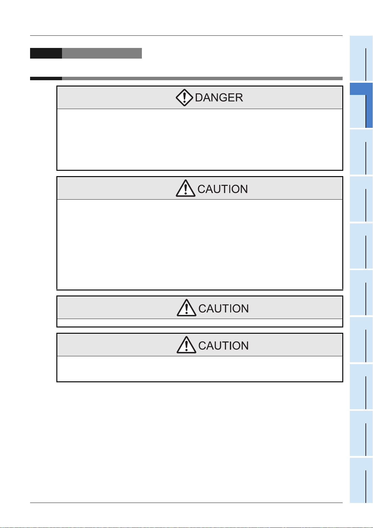
Safety Precautions
(Read these precautions before using.)
Before installation, operation, maintenance or inspection of this product, thoroughly read through and
understand this manual and the associated manuals. Also, take care to handle the module properly and
safely.
This manual classifies the safety precautions into two categories: and .
Indicates that incorrect h andling may cause hazardous conditions, result ing in death or severe
injury.
Indicates that incorrect h andling may cause hazardous conditio ns, resulting in medium or slight
personal injury or physical damage.
Depending on the circumstances, procedures indicated by may also cause severe injury. In
any case, it is important to follow all usage directions. Store this manual in a safe place so that it can be taken
out and read whenever necessary. Always forward it to the end user.
1. DESIGN PRECAUTIONS
Reference
• Make sure to include the f ollowing safety circuits outside the PLC to ensure safe system op eration even during
external power supply problems o r PLC failure.
Otherwise, malfunctions may cause serio u s ac cid ents.
1) Above all, the following components should be included: an emergency stop circuit, a protection circuit, an
interlock circuit for opposite movements (such as normal vs. reverse rotation), and an interlock circuit (to prevent
damage to the equipment at the upper and lower positioning limits ).
2) Note that when the PLC main unit de tects an error during self diagnosis , such as a watchdog timer error, all
outputs are turned off. Also, when an error that cannot be detected by the PLC main unit occurs in an input/
output control block, output control may be disabled.
External circuits and mechanisms should be designed to ensure safe machinery operation in such cases.
• Observe the following items. Fai lure t o do so may c ause incor rect data- writi ng th roug h nois e to the PLC and result
in PLC failure, machine damage or other accident.
1) Do not bundle the control line together with or lay it close to the main circuit or power line. As a guideline, lay the
control line at least 100mm (3.94") or more away from the main circuit or power line.
Noise may cause malfunctions.
2) Ground the shield wire or shield of a shielded cable. Do not use common grounding with heavy electrical
systems
• During access (ACCESS LED is lit or flickering) to CompactFlash
or power off the FX
Failure to do so may cause CompactFlash
• If the power is turned OFF while the CompactFlash
buffered data is erased. Als o files or CompactFlashTM card itself may be damaged. Do not turn the power OFF
while the ACCESS LED is lit or flickering.
• Do not apply excessive pressure to the power supply cable or power supply connector.
Excessive pressure may cause damage or error.
3U-CF-ADP.
TM
card failures or malfunctions.
TM
card is being accessed (ACCESS LED is lit or flickering), the
TM
card, do not remove the CompactFlashTM card
15
28
Reference
15
28
(1)
Page 4
Safety Precautions
(Read these precautions before using.)
2. INSTALLATION PRECAUTIONS
Reference
• Make sure to shut down all phases of the power supply externally before i nstalling the FX3U-CF-ADP.
Failure to do so may cause electric shock or damage to the product.
• Use the product within the generic environment specifications described in PLC main unit manual (Hardware
Edition). Never use the product in areas with excessive dust, oily smoke, conductive dusts, corrosive gas (salt air,
Cl2, H2S, SO2, or NO2), flammable gas, vibration or impacts, or expose i t to high temperature, condensa tion, or
rain and wind. If the prod uct is used in s uch condition s, electric sh ock, fire, malf unctions, dete rioration or d amage
may occur.
• Do not touch the conductive part s of the product directly.
Doing so may cause device failures or malfunctions.
• Install the product securely usin g a DI N ra il or mounting screws.
• Install the product on a flat surface.
If the mounting surface is rough, undue force will be applied to the PC board, thereby causing nonconformities.
• When drilling screw holes or wiring, make sure that cutting and wiri ng debris do not enter the ventilation slits.
Failure to do so may cause fire, equipment failures or malfunctions.
• Be sure to remove the dust proof sheet from the PLC's ventilation port when installation work is completed.
Failure to do so may cause fire, equipment failures or malfunctions.
• Connect the FX3U-CF-ADP securely to special adapter connector.
Loose connections may cause malfunctions.
• Connect the power connector of the power supply cable securely to the CF-ADP power supply connector.
Loose connections may cause malfunctions.
• When inserting a CompactFlashTM card into the FX3U-CF-ADP, push it into the CF card slot until the EJECT button
pops out.
Loose connections may cause malfunctions.
• Before inserting/removing a CompactFlashTM card into/from the FX3U-CF-ADP, set the CF card ACCESS switch to
OFF and confirm that the BUFFER LED and ACCE SS LED are both OFF.
Failure to do so may corrupt data within the CompactFlashTM card.
• When removing a CompactFlashTM card from the FX3U-CF-ADP, make sure to support the CompactFlashTM card
by hand, as it may pop out.
Failure to do so may cause the CompactFlashTM card to fall from the FX3U-CF-ADP an d break.
• Turn off the power to the PLC befor e attaching or detaching the foll owing devices.
Failure to do so may cause device failures or malfunctions.
- Peripheral devices, display modules, expansion boa rds and special adapters
- I/O extension units/blocks, FX Series terminal block and the special function units/blocks
- Battery and memory cassette
22
99
Reference
22
99
3. WIRING PRECAUTIONS
• Make sure to cut off all phases of the power supply externally bef ore attempting wiring work.
Failure to do so may cause electric shock or damage to the product.
• Connect the DC power supply wiring to the dedicated terminal described in this manual.
If an AC power supply is connected to a DC input/output terminal or DC power supply terminal, the PLC will burn
out.
• Connect the DC power supply wiring to the dedicated connector descri bed in this manual.
If an AC power supply is connected to a DC power supply connecto r, the PLC will bu rn out .
• When drilling screw holes or wiring, make sure that cutting and wiri ng debris do not enter the ventilation slits.
Failure to do so may cause fire, equipment failures or malfunctions.
(2)
Reference
28
99
Reference
28
99
Page 5
Safety Precautions
(Read these precautions before using.)
4. STARTUP AND MAINTENANCE PRECAUTIONS
• Make sure to connect the battery co rre c tly . Do n ot c ha rg e, disassemble, heat, short-circuit, or exp o se the battery to
fire.
Doing so may rupture or ignite it.
• Do not touch any terminal while the PLC's power is on.
Doing so may cause electric shock or malfunctions.
• Before modifying or disrupting th e progr am i n opera t ion or runn ing t he PL C, ca ref ul ly rea d th roug h th is manual and
the associated manuals and ensure the safety of the operation.
An operation error may damage the machinery or cause accidents.
• Do not disassemble or modify the PLC.
Doing so may cause fire, equipment failures, or malfunctions.
For repair, contact your local Mitsubishi Electric distributor.
• Turn off the power to the PLC befor e attaching or detaching the foll owing devices.
Failure to do so may cause device failures or malfunctions.
- Peripheral devices, display modules, expansion boa rds and special adapters
- I/O extension units/blocks, FX Series terminal block and the special function units/blocks
- Battery and memory cassette
Reference
28
81
100
Reference
29
81
100
5. DISPOSAL PRECAUTIONS
• Please contact a certified elect r onic wast e dis pos al compan y fo r t he envir on ment all y safe re cy cl ing an d di sp osal of
your device.
6. TRANSPORTATION PRECAUTIONS
• The PLC is a precision instrument. Dur ing transportation, avoid impacts larger tha n those specified in th e general
specifications of the PLC main uni t manual.
Failure to do so may cause failures in the PLC.
After transportation, verify the operations of the PLC.
Reference
15
Reference
15
(3)
Page 6

(4)
Page 7

FX3U-CF-ADP User's Manual
FX3U-CF-ADP
User's Manual
Manual number JY997D35401 Manual revision A Date 6/2009
Foreword
This manual describes the FX3U-CF-ADP CF card special adapter and should be read and understood before
attempting to install the hardware.
Store this manual in a safe place so that you can take it out and read it whenever necessary. Always forward
it to the end user.
This manual confers no industrial property rights or any ri ghts of any other kind, nor does it confer any patent lic enses. Mitsubishi
Electric Corporation cannot be held resp onsible for any problems involving ind ustrial pro perty rights which may oc cur as a resu lt of
using the contents noted in thi s manual.
© 2009 MITSUBISHI ELECTRIC CORPORATION
1
Page 8

FX3U-CF-ADP User's Manual
Outline Precautions
• This manual provides information for the use of the FX3U-CF-ADP CF card special adapter.
The manual has been written to be used by trained and competent personnel. The definition of such a
person or persons is as follows;
1) Any engineer who is responsible for the planning, design and construction of automatic equipment using
the product associated with this manual should be of a competent nature, trained and qualified to the
local and national standards required to fulfill that role. These engineers should be fully aware of all
aspects of safety with aspects regarding to automated equipment.
2) Any commissioning or maintenance engineer must be of a competent nature, trained and qualified to the
local and national standards required to fulfill the job. These engineers should also be trained in the use
and maintenance of the completed product. This includes being familiar with all associated manuals and
documentation for the product. All maintenance sho uld be carried out in accordance with est ablished
safety practices.
3) All operators of the completed equipment should be trained to use that product in a safe and coordinated
manner in compliance with established safety practices. The operators should also be familiar with
documentation that is connected with the actual operation of the completed equipment.
Note: the term 'completed equipment' refers to a third party constructed device that contains or uses the
product associated with this manual.
• This product has been manufactured as a general-purpose part for general industries, and has not been
designed or manufactured to be incorporated in a device or system used in purposes related to human life.
• Before using the product for special purposes such as nuclear power, electric power, aerospace, medicine
or passenger movement vehicles, consult with Mitsubishi Electric.
• This product has been manufactured under strict quality control. However when installing the product
where major accidents or losses could occur if the product fails, install appropriate backup or failsafe
functions into the system.
• When combining this product with other products, please confirm the standards and codes of regulation to
which the user should follow. Moreover, please confirm the compatibility of this product with the system,
machines, and apparatuses to be used.
• If there is doubt at any stage during installation of the product, always consult a professional electrical
engineer who is qualified and trained in the local and national standards. If there is doubt about the
operation or use, please consult the nearest Mitsubishi Electric distributor.
• Since the examples within this manual, technical bulletin, catalog, etc. are used as reference; please use it
after confirming the function and safety of the equipment and system. Mitsubishi Electric will not accept
responsibility for actual use of the product based on these illustrative examples.
• The content, specification etc. of this manual may be changed for improvement without notice.
• The information in this manual has been carefully checked and is believed to be accurate; however, if you
notice any doubtful point, error, etc., please contact the nearest Mitsubishi Electric distributor.
Registration
• CompactFlash is a trademark of SanDisk Corporation in the United States and other countries.
• The company name and the product name to be described in this manual are the registered trademarks or
trademarks of each company.
2
Page 9

FX3U-CF-ADP User's Manual
Table of Contents
SAFETY PRECAUTIONS..................................................................................................(1)
Standards...................................................................................................................................7
Certification of UL, cUL standards .......................................................................................................7
Compliance with EC directive (CE Marking)........................................................................................7
Associated Manuals..................................................................................................................9
Generic Names and Abbreviations Used in the Manual......................................................10
Reading the Manual .................................................... ............................................................ 12
1. Introduction 13
1.1 Outline...........................................................................................................................................13
1.2 External Dimensions and Part Names..........................................................................................13
1.3 Power and status LEDs.................................................................................................................14
2. Specification 15
2.1 General specifications...................................................................................................................16
2.2 Power supply specification............................................................................................................16
2.3 Performance specification.............................................................................................................16
2.4 CF card ACCESS switch specification..........................................................................................17
TM
2.5 CompactFlash
2.6 Applicable CompactFlash
card specification.............................................................................................. 17
TM
card.................................................................................................17
Table of Contents
3. System Configuration 18
3.1 General configuration....................................................................................................................18
3.2 Applicable PLC..............................................................................................................................19
3.2.1 Connectable PLC ..........................................................................................................................19
3.2.2 Applicable versions of the programming tool.................................................................................19
3.3 Connection with PLC.....................................................................................................................19
3.4 Assignment of channels................................................................................................................20
4. Installation 22
4.1 CF-ADP Connection......................................................................................................................23
4.2 DIN rail mounting ..........................................................................................................................24
4.3 Direct mounting.............................................................................................................................25
4.4 Inserting and Removal Procedures...............................................................................................26
4.4.1 Inserting the CompactFlashTM card .................................................... ... .......................................26
4.4.2 Removing the CompactFlash
TM
card............................................................. ... ............................27
3
Page 10

FX3U-CF-ADP User's Manual
5. Wiring 28
5.1 Which Power Supply Cable to Use...............................................................................................29
5.1.1 Power supply cable .......................................................................................................................29
5.1.2 Preparing the power cable by yourself ..........................................................................................29
5.2 Power Supply Wiring.....................................................................................................................30
5.2.1 Power supply wiring.......................................................................................................................30
5.3 Grounding .....................................................................................................................................30
5.4 Power OFF procedure...................................................................................................................31
5.4.1 Power OFF procedure using the CF card ACCESS switch...........................................................31
5.4.2 Power OFF procedure using the applied instruction for the CF-ADP............................................31
5.4.3 Caution on power OFF..................................................................................................................31
5.5 Connection of the power supply cable..........................................................................................32
5.5.1 Connection/removal of the power supply cable.............................................................................32
6. Functions 33
6.1 Details of functions........................................................................................................................33
6.2 Status information.........................................................................................................................34
Table of Contents
7. Before Programming 35
7.1 File format available in the CF-ADP..............................................................................................35
7.1.1 Files created by the CF-ADP.........................................................................................................35
7.1.2 Files created by the user........................ ... ... .................................... ... ..........................................36
7.1.3 Characters available in files...........................................................................................................37
7.1.4 Data size calculation......................................................................................................................38
7.1.5 Data writing destination.................................................................................................................39
7.1.6 File ID............................................................................................................................................40
7.1.7 FIFO file.........................................................................................................................................41
7.2 Directory structure.........................................................................................................................42
7.3 Date/time setting...........................................................................................................................42
7.4 General Rules for Applied Instructions..........................................................................................43
7.4.1 Expression and operation type of applied instructions..................................................................43
7.4.2 Programming using "Instruction execution complete" flag and
"Instruction execution abnormal end" flag ................................................................................44
8. CF-ADP Applied Instructions Explanation 46
8.1 CF-ADP Instructions types............................................................................................................46
8.2 Common Items in CF-ADP Instructions........................................................................................46
8.2.1 Function and operation..................................................................................................................46
8.2.2 Cautions on programming.............................................................................................................47
8.3 FNC 300 - FLCRT / File create•check ..........................................................................................48
8.3.1 Detailed explanation of setting data..............................................................................................49
8.4 FNC 301 - FLDEL / File delete•CF card format ............................................................................51
8.4.1 Detailed explanation of setting data..............................................................................................52
8.5 FNC 302 - FLWR / Data write.......................................................................................................54
8.5.1 Detailed explanation of setting data..............................................................................................56
8.5.2 Writing data of same type..............................................................................................................57
8.5.3 Writing data of different types........................................................................................................61
8.6 FNC 303 - FLRD / Data read ........................................................................................................68
8.6.1 Detailed explanation of setting data..............................................................................................69
8.6.2 Reading data of the same type from a file.....................................................................................70
8.6.3 Reading data of different types from a file.....................................................................................71
4
Page 11

FX3U-CF-ADP User's Manual
8.7 FNC 304 - FLCMD / FX3U-CF-ADP command............................................................................. 74
8.7.1 Detailed explanation of setting data..............................................................................................75
8.8 FNC 305 - FLSTRD / FX3U-CF-ADP status read ......................................................................... 76
8.8.1 Detailed explanation of setting data..............................................................................................77
8.9 Contents of Related Devices.........................................................................................................80
9. Program Examples 81
9.1 System Configuration....................................................................................................................81
9.2 Program Example 1 ......................................................................................................................82
9.2.1 Operation details ...........................................................................................................................82
9.2.2 Example of a 32-bit decimal type file in "csv" format after writing.................................................82
9.2.3 Device Assignments......................................................................................................................83
9.2.4 Sequence Program........................................................................................................................84
9.3 Program Example 2 ......................................................................................................................89
9.3.1 Operation details ...........................................................................................................................89
9.3.2 Example of a mixed type file in "csv" format after writing..............................................................89
9.3.3 Device Assignments......................................................................................................................89
9.3.4 Sequence Program........................................................................................................................91
9.4 Program Example 3 ......................................................................................................................97
9.4.1 Operation details ...........................................................................................................................97
9.4.2 Device Assignments......................................................................................................................97
9.4.3 Sequence Program........................................................................................................................98
Table of Contents
10. Troubleshooting 99
10.1 Troubleshooting procedure.......................................................................................................101
10.1.1 LED status check.......................................................................................................................101
10.1.2 Troubleshooting by error code...................................................................................................101
10.1.3 Error Code List and Action........................................................................................................102
10.2 Diagnostics on the PLC Main Unit ............................................................................................107
10.2.1 POWER(POW) LED [on/flashing/off].........................................................................................107
10.2.2 BATT(BAT) LED [on/off]............................................................................................................107
10.2.3 ERROR(ERR) LED [on/flashing/off]..........................................................................................108
Appendix A: Related Devices 109
Appendix A-1 Related Device List ............................................................................................ 109
Appendix A-2 Details of related devices...................................................................................110
Appendix A-2-1 Instruction execution complete [M8029] .....................................................................110
Appendix A-2-2 Instruction execution abnormal end [M8329]..............................................................110
Appendix A-2-3 CF-ADP instruction executing [M8402, M8422]..........................................................110
Appendix A-2-4 CF-ADP unit ready [M8404, M8424]...........................................................................110
Appendix A-2-5 CF card mount status [M8405, M8425] ......................................................................111
Appendix A-2-6 CF-ADP status renewal stop [M8410, M8430] ...........................................................111
Appendix A-2-7 CF-ADP instruction error [M8418, M8438] .................................................................111
Appendix A-2-8 CF-ADP status [D8406, D8426]..................................................................................111
Appendix A-2-9 CF-ADP version [D8408, D8428]................................................................................111
Appendix A-2-10 Step number of an instruction for the CF-ADP where an error has occurred
[D8415, D8414][D8435, D8434]..............................................................................112
Appendix A-2-11 Error code in detail for CF-ADP instructions [D8417, D8437]...................................112
Appendix A-2-12 Error code for CF-ADP instructions [D8418, D8438]................................................112
Appendix A-2-13 Operation mode display [D8419, D8439]..................................................................112
5
Page 12

FX3U-CF-ADP User's Manual
Appendix B: Version Information 113
Appendix B-1 Version information ............................................................................................113
Appendix B-1-1 Version check method................................................................................................113
Appendix B-1-2 Version upgrade history..............................................................................................113
Warranty.................................................................................................................................115
Revised History.....................................................................................................................116
Table of Contents
6
Page 13

FX3U-CF-ADP User's Manual
Standards
Certification of UL, cUL standards
FX3U-CF-ADP units comply with the UL standards (UL, cUL).
UL, cUL File number :E95239
Regarding the standards that comply with the main unit, please refer to either the FX series product catalog or
consult with your nearest Mitsubishi product provider.
Compliance with EC directive (CE Marking)
This document does not guarantee that a mechanical system including this product will comply with the
following standards.
Compliance to EMC directive and LVD directive for the entire mechanical module should be checked by the
user / manufacturer. For more information please consult with your nearest Mitsubishi product provider.
Regarding the standards that comply with the main unit, please refer to either the FX series product catalog or
consult with your nearest Mitsubishi product provider.
Standards
Requirement for Compliance with EMC directive
The following products have shown compliance through direct testing (of the identified standards below) and
design analysis (through the creation of a technical construction file) to the European Directive for
Electromagnetic Compatibility (89/336/EEC) when used as directed by the appropriate documentation.
Type: Programmable Controller (Open Type Equipment)
Models: MELSEC FX
from June 1st, 2009 FX
EN61131-2:2003
Programmable controllers
- Equipment requirements and tests
3U series manufactured
3U-CF-ADP
Standard Remark
Compliance with all relevant aspects of the standard.
EMI
• Radiated Emissions
• Conducted Emissions
EMS
• Radiated electromagnetic field
• Fast Transient burst
• Electrostatic discharge
• High-energy surge
• Voltage drops and iterruptions
• Conducted RF
• Power frequency magnetic field
7
Page 14
FX3U-CF-ADP User's Manual
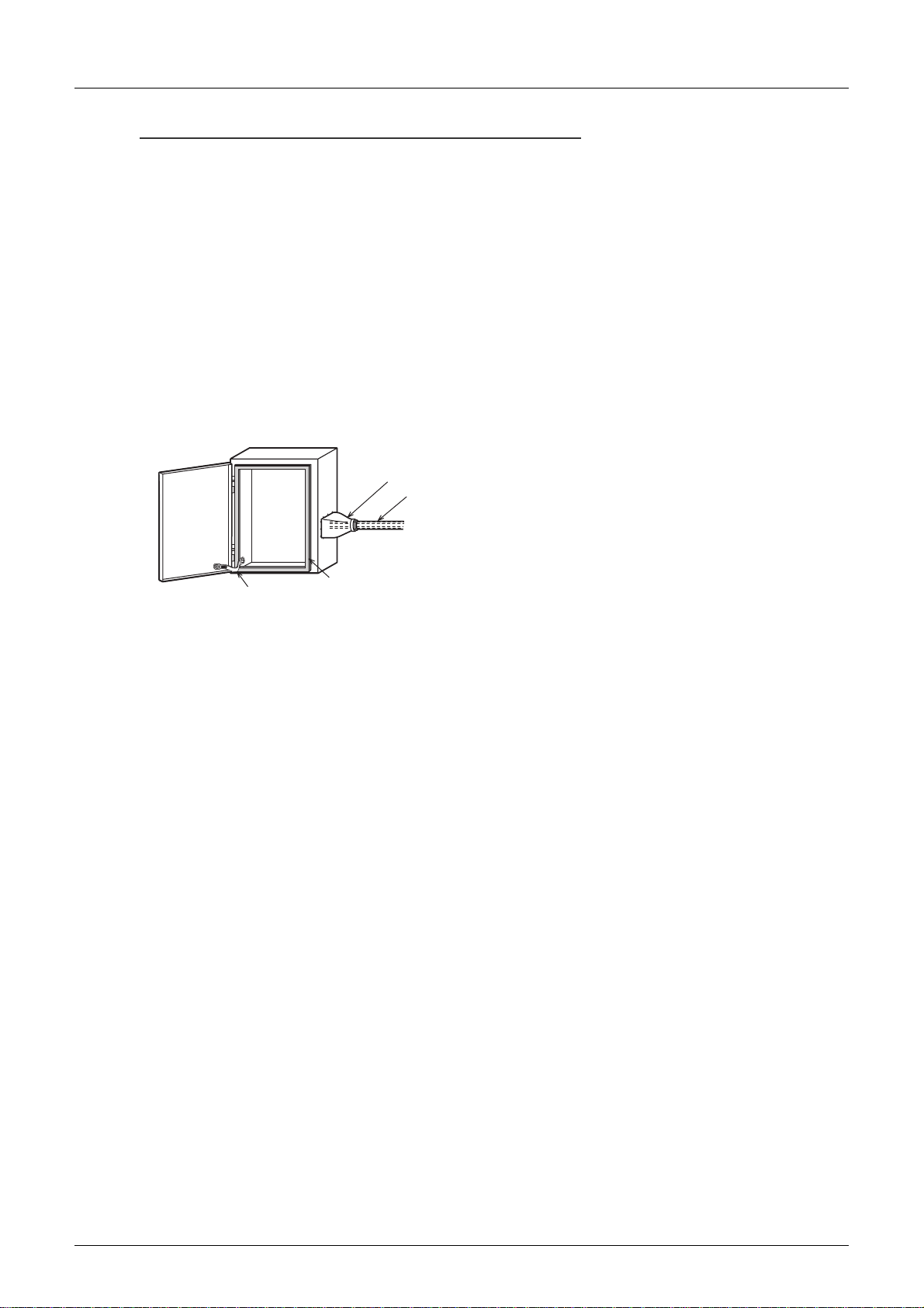
Caution to conform with EC Directives
• Installation in Enclosure
Programmable logic controllers are open-type devices that must be installed and used within conductive
control cabinets. Please use the programmable logic controller while installed within a conductive shielded
control cabinet. Please secure the cabinet door to the control cabinet (for conduction).
Installation within a control cabinet greatly affects the safety of the system and aids in shielding noise from
the programmable logic controller.
• Control cabinet
- The control cabinet must be conductive.
- Ground the control cabinet with the thickest possible grounding cable.
- To ensure that there is electric contact between the control cabinet and its door, connect the cabinet and
its doors with thick wires.
- In order to suppress the leakage of radio waves, the control cabinet structure must have minimal
openings. Also, wrap the cable holes with a shielding cover or other shielding devices.
- The gap between the control cabinet and its door must be as small as possible by attaching EMI gaskets
between them.
Standards
Shielding cover
Shielded cable
Wires*1
EMI gasket
*1. These wires are used to improve the conductivity between the door and control cabinet.
8
Page 15
FX3U-CF-ADP User's Manual
Associated Manuals
Only the installation manual is packed together with the FX3U-CF-ADP special adapter.
For a detailed explanation of the FX
For the hardware information and instructions on the PLC main unit, refer to the respective manuals.
Title of manual
Manual for the Main Unit
FX3U Series PLCs Main Unit
Supplied
Manual
Additional
Manual
FX3UC Series PLCs Main Unit
Supplied
Manual
Supplied
Manual
Supplied
Manual
Additional
Manual
Programming for FX
Additional
Manual
Manuals for communication control
Additional
Manual
Manuals for FX3U-CF-ADP CF card special adapter
Supplied
Manual
Additional
Manual
3U Series
FX
Hardware Manual
FX3U Series
User's Manual
- Hardware Edition
FX3UC(D,DSS) Series
Hardware Manual
FX3UC-32MT-LT-2
Hardware Manual
FX3UC-32MT-LT
Hardware Manual
(Only Japanese document)
FX3UC Series
User's Manual
- Hardware Edition
3G/FX3U/FX3UC Series
FX
3G/FX3U/FX3UC Series
Programming Manual
- Basic & Applied
Instruction Edition
FX Series User's Manual Data Communication
Edition
FX3U-CF-ADP
Installation Manual
FX3U-CF-ADP
User's Manual
(This Manual)
3U-CF-ADP special adapter, refer to this manual.
Refer to these manuals
Refer to the appropriate equipment manual
For a detailed explanation, refer to an additional manual
Document
number
JY997D18801
JY997D16501
JY997D28601
JY997D31601
JY997D12701
JY997D28701
JY997D16601
JY997D16901
JY997D35201
JY997D35401
Describes FX
and installation extracted from the FX
Hardware Edition.
For details, refer to FX
Hardware Edition.
Describes FX3U Series PLC specification details for I/O,
wiring, installation and maintenance.
Describes FX3UC(D,DSS) Series PLC specification for I/
O, wiring and installation extracted from the FX3UC
Series User's Manual - Hardware Ed ition.
For details, refer to FX3UC Series User's Manual Hardware Edition.
Describes FX3UC-32MT-LT-2 specification for I/O,
wiring and installation extracted from t he FX3UC User's
Manual - Hardware Edition.
For details, refer to FX3UC Series User's Manual Hardware Edition.
Describes FX3UC-32MT-LT specification for I/O, wiring
and installation extracted from the FX3UC User's Manual
- Hardware Edition.
For details, refer to FX3UC Series User's Manual Hardware Edition.
Describes FX3UC Series PLC specification details
for I/O, wiring, installation an d maintenance.
Describes FX3G/FX3U/FX3UC Series PLC
programming for basic/applied
instructions and devices.
Details of N:N Network, parallel link, computer link and
non-protocol communication (RS instructions, FX2N-
232IF)
Describes installation specifications for the FX3U-CF-
ADP CF card special adapter extracted from the FX3U-
CF-ADP User's Manual.
For details, refer to FX3U-CF-ADP User's Manual.
Describes details of the FX3U-CF-ADP C F card special
adapter.
Description Model code
3U Series PLC specification for I/O, wiring
3U User's Manual -
3U Series User's Manual -
Associated Manuals
-
09R516
-
-
-
09R519
09R517
09R715
-
09R720
9
Page 16

FX3U-CF-ADP User's Manual
Generic Names and Abbreviations Used in the Manual
Generic Names and Abbreviations Used in the Manual
Generic name or abbreviation Description
PLC
FX3U series Generic name for FX3U Series PLC
FX3U PLC or main unit Generic name for FX3U Series PLC main unit
FX3UC series Generic name for FX3UC Series PLC
FX3UC PLC or main unit Generic name for FX3UC Series PLC main unit
Expansion board
Generic name for expansion board
Expansion board
Special adapter
Special adapter
CF-ADP Abbreviated name for FX3U-CF-ADP
Extension equipment
I/O extension unit/block
Special function unit/block or
Special extension unit
Special function unit Generic name for special function unit
Special function block
Optional unit
Memory cassette Generic name for FX3U-FLROM-16, FX3U-FLROM-64, FX3U-FLROM-64L
CF card or CompactFlashTM card
Memory card adaptor Generic name for GT05-MEM-ADPC
Peripheral unit
Peripheral unit Generic name for programming software, handy programming panel, and indicator
Programming tool
Programming tool Generic name for programming softwar e and handy programming panel
Programming software Generic name for programming softw are
GX Developer
FX-PCS/WIN(-E) Generic name for FX-PCS/WIN or FX-PCS/WIN-E programming software package
Handy programming panel (HPP) Generic name for FX-30P, FX-20P(-E) and FX-10P(-E)
Indicator
GOT1000 series Generic name for GT15, GT11 and GT10
GOT-900 series Generic name for GOT-A900 series and GOT-F900 series
GOT-A900 series Generic name for GOT-A900 series
GOT-F900 series Generic name for GOT-F900 series
ET-940 series
The number of connectable units, how ever, depends on the type of main unit .
To check the number of connectable units, refer to the User's Manual - Hardware Editon of the main
unit to be used for your system.
Generic name for high-speed input/ output special adapter, communic ation special adapter, analog
special adapter, and CF card special adapter.
The number of connectable units, how ever, depends on the type of main unit .
To check the number of connectable units, refer to the User's Manual - Hardware Editon of the main
unit to be used for your system.
Generic name for input/output p owered extension unit and input /output extension block
The number of connectable units, how ever, depends on the type of main unit .
To check the number of connectable units, refer to the User's Manual - Hardware Edition of the main
unit to be used for your system.
Generic name for special function unit and special function block
The number of connectable units, how ever, depends on the type of main unit .
To check the number of connectable units, refer to the User's Manual - Hardware Edition of the main
unit to be used for your system.
Generic name for special function block
The number of connectable units, how ever, depends on the type of main unit .
To check the number of connectable units, refer to the User's Manual - Hardware Edition of the main
unit to be used for your system.
Generic name for GT05-MEM-128MC, GT05-MEM-256MC, GT05-MEM-512MC, GT05-MEM-1GC,
GT05-MEM-2GC
Generic name for SW D5C-GPPW-J/SW D5C-GPPW-E programming software package
Generic name for ET-940 series
Only manuals in Japanese are available for these products
10
Page 17

FX3U-CF-ADP User's Manual
Generic name or abbreviation Description
Manual
FX3U Hardware Edition FX3U Series User's Manual - Hardware Edition
FX3UC Hardware Edition FX3UC Series User's Manual - Hardware Edition
Programming manual FX3G/FX3U/FX3UC Series Programming Manual - Basic and App lied Instructions Edition
Communication control Edition FX Series User's Manual - Data Communication Edition
Analog control Edition FX3G/FX3U/FX3UC Series User' s Manual - Analog Control Edition
Positioning control Edition FX3G/FX3U/FX3UC Series User's Manual - Positioning Control Edition
Generic Names and Abbreviations Used in the Manual
11
Page 18
FX3U-CF-ADP User's Manual
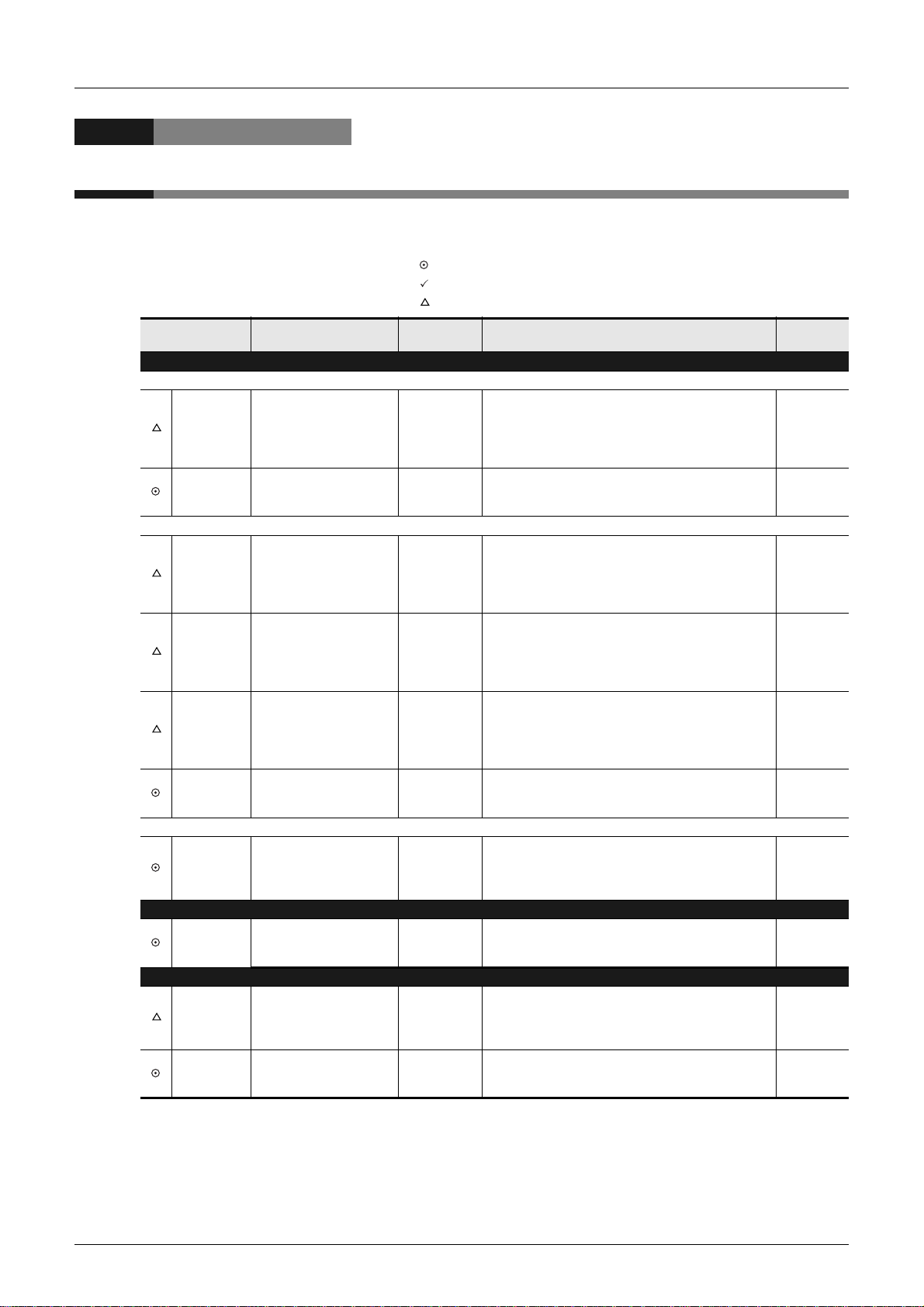
Reading the Manual
In this manual, the following formats are used for describing the common items.
Reading the Manual
Shows the manual title.
This area shows the
manual title for the current
page.
Shows the title of the chapter and the title
of the section.
This area shows the title of the chapter and the
title of the section for the current page.
Indexes the chapter number.
The right side of each page
indexes the chapter number
for the page currently opened.
Shows the reference.
The " " mark indicates
a reference destination
and reference manual.
12
The above is different from the actual page, as it is provided for explanation only.
Page 19
FX3U-CF-ADP User's Manual
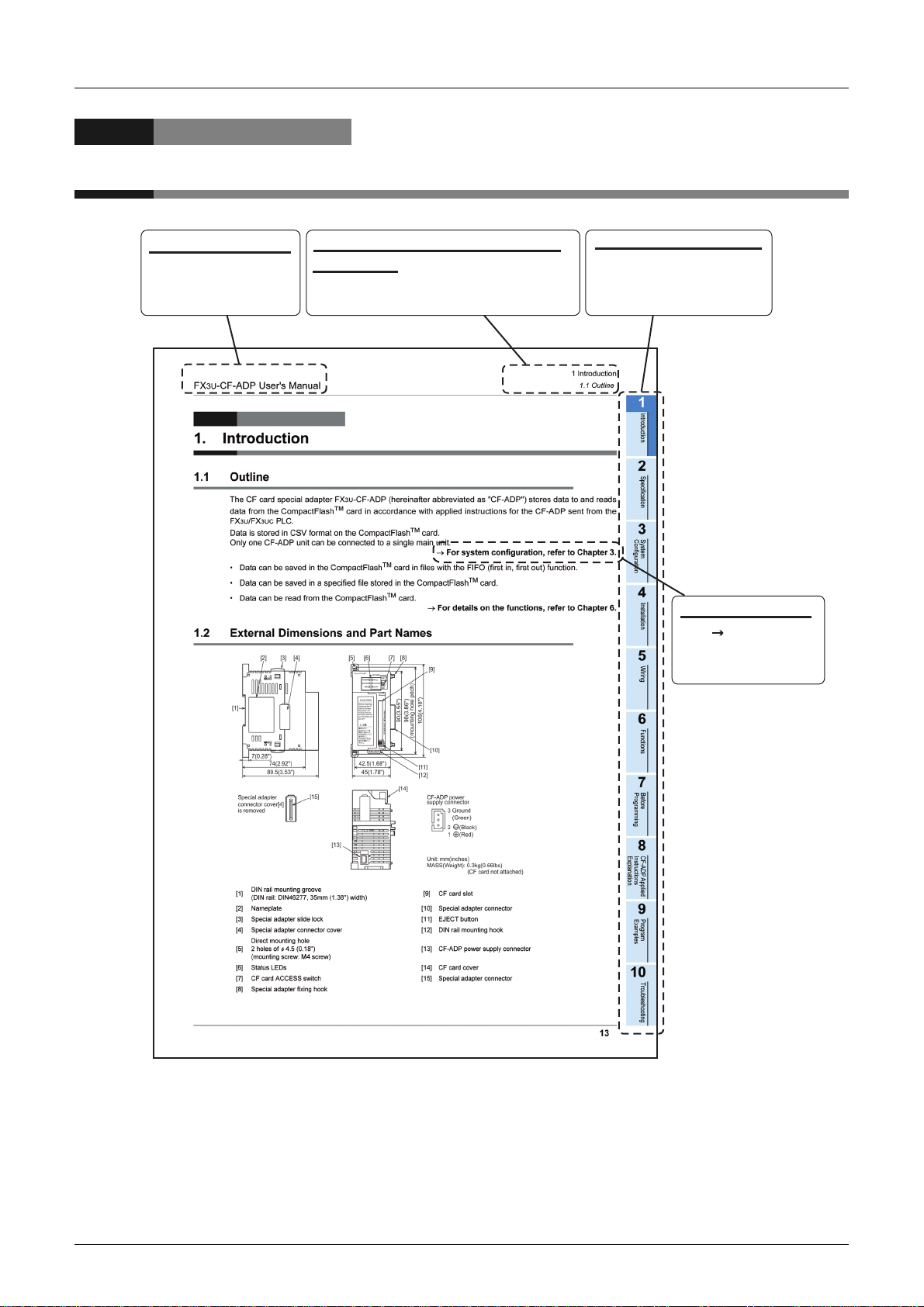
1. Introduction
1.1 Outline
The CF card special adapter FX3U-CF-ADP (hereinafter abbreviated as "CF-ADP") stores data to and reads
data from the CompactFlash
3U/FX3UC PLC.
FX
Data is stored in CSV format on the CompactFlash
Only one CF-ADP unit can be connected to a single main unit.
• Data can be saved in the CompactFlash
• Data can be saved in a specified file stored in the CompactFlash
• Data can be read from the CompactFlash
1 Introduction
1.1 Outline
TM
card in accordance with applied instructions for the CF-ADP sent from the
TM
card.
→ For system configuration, refer to Chapter 3.
TM
card in files with the FIFO (first in, first out) function.
TM
card.
TM
card.
→ For details on the functions, refer to Chapter 6.
Configuration
1
Introduction
2
Specification
3
System
4
Installation
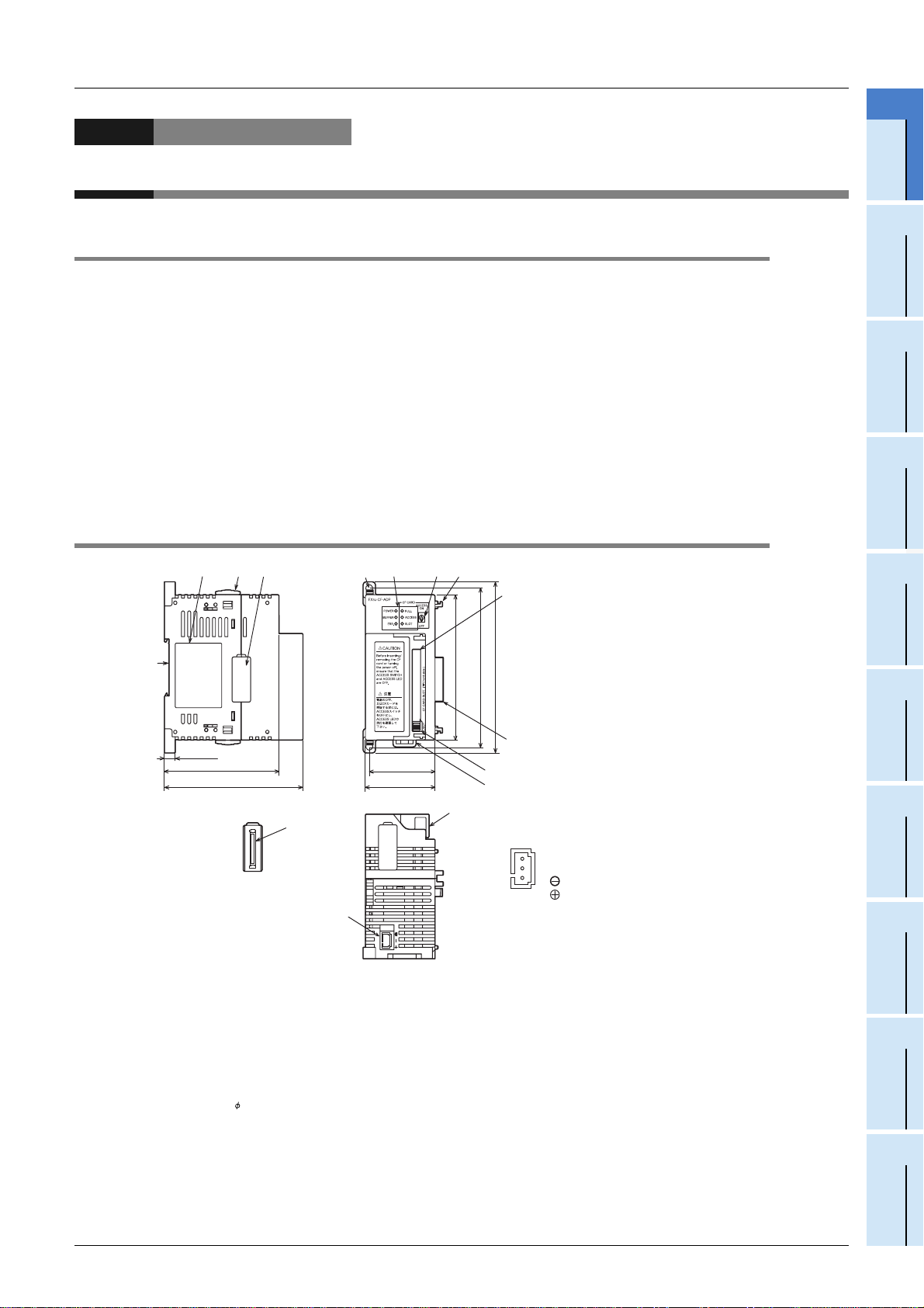
1.2 External Dimensions and Part Names
[6][5] [8][7]
42.5(1.68")
45(1.78")
90(3.55")
98(3.86")
106(4.18")
(mounting hole pitch)
[11]
[12]
[14]
[1]
7(0.28")
89.5(3.53")
Special adapter
connector cover[4]
is removed
[3][2] [4]
74(2.92")
[15]
[13]
[9]
[10]
CF-ADP power
supply connector
3 Ground
(Green)
21(Black)
(Red)
Unit: mm(inches)
MASS(Weight): 0.3kg(0.66lbs)
(CF card not attached)
5
Wiring
6
Functions
7
Before
Programming
8
CF-ADP Applied
Instructions
Explanation
DIN rail mounting groove
[1]
(DIN rail: DIN46277, 35mm (1.3 8") width)
[2] Nameplate [10] Special adapter connector
[3] Special adapter slide lock [11] EJECT button
[4] Special adapter connector cover [12] DIN rail mounting hook
Direct mounting hole
[5]
2 holes of 4.5 (0.18")
(mounting screw: M4 screw)
[6] Status LEDs [14] CF card cover
[7] CF card ACCESS switch [15] Special adapter connector
[8] Special adapter fixing hook
[9] CF card slot
[13] CF-ADP power supply connector
13
9
Program
Examples
10
Troubleshooting
Page 20

FX3U-CF-ADP User's Manual
1.3 Power and status LEDs
LED display Color Status Description
POWER Green
BUFFER Green
ERR. Red
FULL Red
ACCESS Red
SLOT Green
OFF Power is not being supplied fro m the external power supply (24V D C ).
ON Power is being supplied from the external power supply (24V DC).
OFF Data is not stored in the internal buffer.
ON Data is stored in the internal buffer.
OFF No errors.
ON
CF write error, CompactFlashTM card error, etc. has occurred.
OFF
The CompactFlashTM card has free space.
Flicker
The free space in the CompactFlashTM card is 20% or less of the full capacity.
The CompactFlashTM card has no free space.
ON
The free space in the CompactFlashTM card is 1% or less of the full capacity.
OFF
CompactFlashTM card not accessed.
ON
CompactFlashTM card being accessed.
The CompactFlashTM card is not inserted, or the slot is in the CompactFlashTM card unmounted
OFF
status.
ON
The CompactFlashTM card is inserted, or the slot is in the CompactFlashTM card mounted status.
1 Introduction
1.3 Power and status LEDs
14
Page 21
FX3U-CF-ADP User's Manual
2. Specification
DESIGN PRECAUTIONS
• Make sure to include the following safety circuits outside the PLC to ensure safe system operation even during external power supply
problems or PLC failure.
Otherwise, malfunctions may caus e serious accidents.
1) Above all, the followi ng components should be included: an emerg ency stop circuit, a protection circuit , an interlock circuit for
opposite movements (such as normal vs. r everse r otation), and an int erlock cir cuit (to pr event da mage to the e quipment at the
upper and lower positioning limits).
2) Note that when the PLC main unit detects an error during self diagnosis, such as a watchdog timer error, all outputs are turned off.
Also, when an error th at ca nnot be detec ted by t he PLC main u nit occ urs i n an inp ut/ out put c ontrol bloc k, outp ut cont rol ma y be
disabled.
External circuits and mechanisms should be designed to ensure safe machinery operation in such cases .
DESIGN PRECAUTIONS
2 Specification
Configuration
1
Introduction
2
Specification
3
System
4
Installation
• Observe the following items. F ailure to do so may cause i ncorrect data-writing th rough noise to the PLC and result in PLC failure,
machine damage or other accident.
1) Do not bundle the control line together with or lay it close to the main circuit or power line. As a guideline, lay the control line at
least 100mm (3.94") or more away from the main circuit or power line.
Noise may cause malfunctions.
2) Ground the shield wire or shield of a shielded cable. Do not use common grounding with heavy electrical systems
• During access (ACCESS LED is l it or fli ckering) to Compac tFlashTM card, do not remove the CompactFlashTM card or power off the
CF-ADP.
Failure to do so may cause CompactFlashTM card failures or malfunctions.
• If the power is turned OFF wh ile the Compa ctFlashTM card is being accessed (ACCE SS LED is lit or flicke ring), the buffere d data is
erased. Also files or CompactFlashTM card itself may be damaged. Do not turn the power OFF while the ACCESS LED is lit or
flickering.
• Do not apply excessive pressu re to the power supply cable or power supply connector.
Excessive pressure may cause da mage or error.
DISPOSAL PRECAUTIONS
• Please contact a certified el ectronic waste disposal company for the environmentally safe recycling and disposal of your devi ce.
TRANSPORTATION PRECAUTIONS
• The PLC is a precision instrument. During transportation, avoid impacts larger than those specified in the general specifications of the
PLC main unit manual.
Failure to do so may cause failures in the PLC.
After transportation, verify the operations of the PLC.
5
Wiring
6
Functions
7
Before
Programming
8
CF-ADP Applied
Instructions
Explanation
15
9
Program
Examples
10
Troubleshooting
Page 22

FX3U-CF-ADP User's Manual
2.1 General specifications
For items not listed below, specifications are the same as the of the PLC main unit.
For general specifications, refer to the manual of the PLC main unit.
Item Specification
0 to 55 C (32 to 131 F) ••••• when operating,
Ambient temperature
Dielectric withstand voltage 500V AC for one minute
Insulation resistance
*1
-25 to 75 C (-13 to 167 F) ••••• when stored
5M or more by 500V DC Megger
*1. The upper limit of the ambient temperature shall not exceed "20 C" below the upper limit of the
CompactFlash
TM
card operating temperature.
Example : When the upper limit of the CompactFlash
limit of the ambient temperature is 55 C.
2.2 Power supply specification
2 Specification
2.1 General specifications
→ Refer to the FX
→ Refer to the FX
Between all terminals and ground terminal
TM
card operating temperature is 75 C, the upper
3U Hardware Edition
3UC Hardware Edition
Item Specification
Power supply voltage 24V DC +20% -15% Ripple (p-p) within 5%
Adapter driving
power supply
Interface driving power supply
Permitted instantaneous
power failure time
Current consumption
2.3 Performance specification
Item Specification
Data transfer method Depends on the applied instruction sent from the main un it.
Clock data Operates based on the clock data in the main unit.
DOS file system FAT16
The maximum data capacity 2GB
The maximum file size 512MB (Per 1 file)
Data format CSV format
The number of the maximum files 63 file (When the FIFO function is not used)
FIFO functional file 1 pattern. The file name is automatically assigned.
• Standard file
Data storage directory
File name type
Number of I/O occupied points
Number of connectable units to the
main unit
\FX3U_CF\DATA\. (The directory name is fixed.)
• FIFO file
\FX3U_CF\DATA\FIFO\. (The directory name is fixed.)
8.3 file name (The extensi on is fixe d to " CSV" .) (Hal f-w idth a lpha numer ic c haract ers a nd s ymbols
and character strings allowed in the MS-DOS)
0 point
(This number is not related to the maximum number of input/o utput points of the PLC.)
*1
1 unit
Operation continues when the instantaneous power failure is shorter than 1ms.
130mA
Connect a 24V DC power supply to the power supply connector.
50mA / 5V DC
5V DC power is supplied internally from the main unit.
16
*1. The CF-ADP is handled in the same way as communication expansion boards and communication
special adapters, and occupies 1 communication channel.
Page 23

FX3U-CF-ADP User's Manual
2.4 CF card ACCESS switch specification
Setting item Description
ON
*1
OFF
*1. Turn OFF the CF card ACCESS switch, and then confirm that the BUFFER LED and ACCESS LED
are completely OFF before removing the CompactFlash
ADP.
Access to the CompactFlashTM card enabled
Access to the CompactFlashTM card disabled
2 Specification
2.4 CF card ACCESS switch spec if ic a t io n
TM
card or turning OFF the power of the CF-
1
Introduction
2
Specification
2.5 CompactFlashTM card specification
Item Specification
Operating ambient humidity 5 to 95%RH (no condensation)
Power supply voltage 3.3V 150mA or less
Connector shape Type I
Format form
Data capacity 2GB or less
Connector terminal Gilding
No. of installable cards 1
FAT16
(The CompactFlashTM card shall be formatted in accordance with the FAT16 in advance.)
2.6 Applicable CompactFlashTM card
The following CompactFlashTM card are applicable for the CF-ADP.
Model Description
GT05-MEM-128MC Flash ROM 128MB
GT05-MEM-256MC Flash ROM 256MB
CompactFlashTM card
GT05-MEM-512MC Flash ROM 512MB
GT05-MEM-1GC Flash ROM 1GB
GT05-MEM-2GC Flash ROM 2GB
Configuration
3
System
4
Installation
5
Wiring
6
Functions
Caution
The life of a CompactFlash
Generally, at the end of the operational life, the CompactFlash
Please use it ensuring sufficient availability.
TM
card is expired when data is written to it a specified number of times.
TM
card has reduced capabilities.
7
Before
Programming
8
CF-ADP Applied
Instructions
Explanation
9
Program
Examples
10
Troubleshooting
17
Page 24
FX3U-CF-ADP User's Manual
3. System Configuration
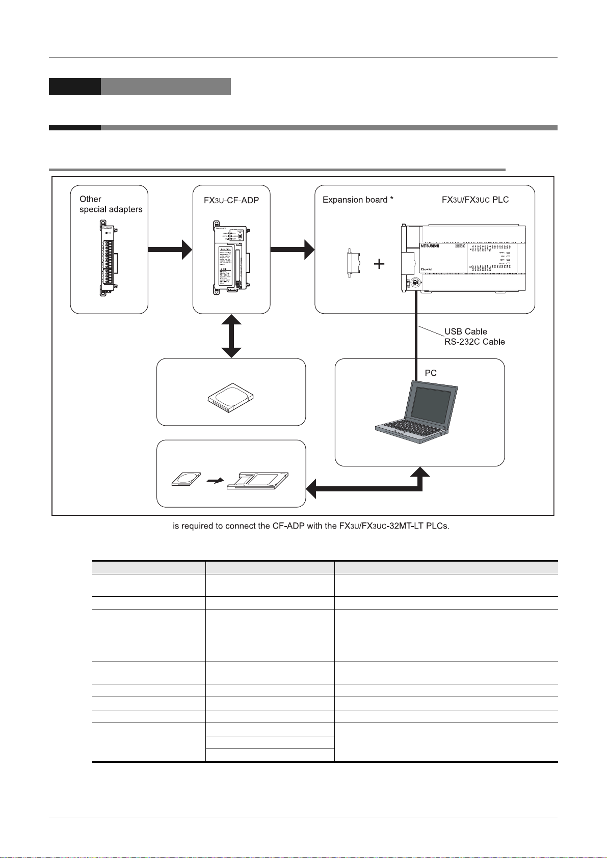
3.1 General configuration
3 System Configuration
3.1 General configuration
CompactFlashTM card
TM
CompactFlash
card
Memory card
adapter
*An expansion board
Component list
Part name Model name Remarks
CF card special adapter FX3U-CF-ADP
PLC FX
CompactFlashTM card
Memory card adapter GT05-MEM-ADP
PC software GX Developer PLC programming software.
PC - USB cable FX-USB-AW Cable with RS-422/USB converter between a FX PLC and PC.
RS-232C cable
3U/FX3UC PLC -
GT05-MEM-128MC,
GT05-MEM-256MC,
GT05-MEM-512MC,
GT05-MEM-1GC,
GT05-MEM-2GC
F2-232CAB-1
FX-422CAB0
An expansion board is requir ed to connect th e CF-ADP with the
3U/FX3UC-32MT-LT PLCs.
FX
CompactFlashTM cards available for the CF-ADP.
The memory card adapter is used to convert a CF card into a
memory card (Type II).
PC connection cable and interface.FX-232AWC-H
18
Page 25
FX3U-CF-ADP User's Manual
3.2 Applicable PLC
3.2.1 Connectable PLC
Model name Applicability
FX3U Series PLC
FX3UC Series PLC
The version number can be checked by reading the last three digits of device D8001.
*1. An expansion board is required to connect the CF-ADP with FX
*2. The FX
*1
*1*2
3UC-32MT-LT-2 PLC is due to be upgraded later.
3.2.2 Applicable versions of the programming tool
Ver. 2.61 and later
Only one CF-ADP unit can be connected to a mai n un it.
Ver. 2.61 and later
Only one CF-ADP unit can be connected to a mai n un it.
3 System Configuration
3.2 Applicable PLC
3U/FX3UC-32MT-LT PLCs.
Configuration
1
Introduction
2
Specification
3
System
1. GX Developer
Use the programming tool with the following version number to create programs for the CF-ADP of the FX3U/
3UC Series PLC.
FX
Software Applicability
GX Developer
• SW D5C(F)-GPPW-J
• SW D5C(F)-GPPW-E
Caution
If a programming tool with the wrong version number is used, programming will not be possible.
3.3 Connection with PLC
The CF-ADP connects with a FX3U/FX3UC PLC via an interface connector.
Only one CF-ADP unit can be connected to the FX
the CF-ADP with the FX
For details of assignment of channel numbers in the main unit, refer to the following.
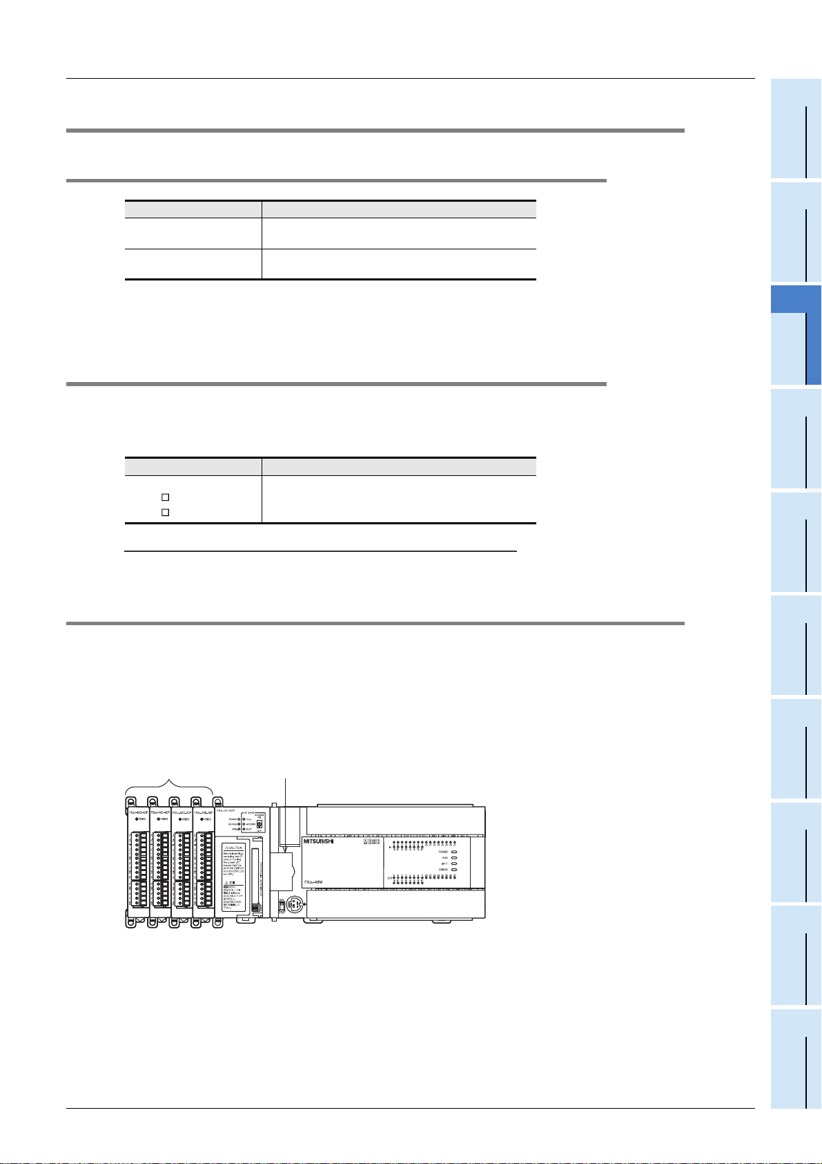
1. FX3U/FX3UC-32MT-LT PLC
Other
special adapters
3U/FX3UC-32MT-LT PLCs.
Expansion board
Ver.8.82L or later
3U/FX3UC PLC. An expansion board is required to connect
Main unit
→ Refer to Section 3.4
Programming
4
Installation
5
Wiring
6
Functions
7
Before
FX
3U
-CF-ADP
19
8
CF-ADP Applied
Instructions
Explanation
9
Program
Examples
10
Troubleshooting
Page 26
FX3U-CF-ADP User's Manual
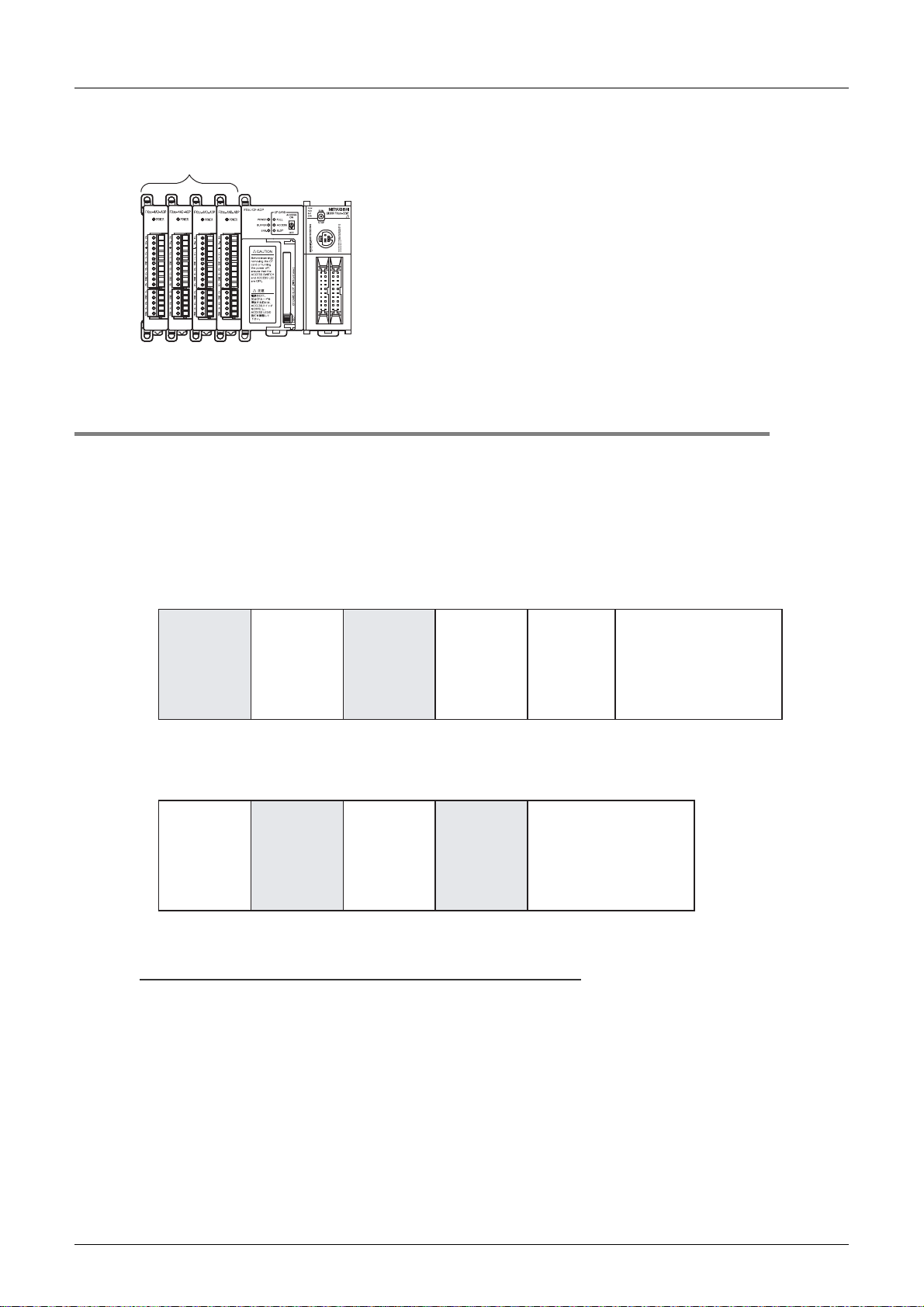
2. FX3UC(D, DSS) PLC
Other
special adapters
Main unit
3U
-CF-ADP
FX
3.4 Assignment of channels
The CF-ADP is handled in the same way as communication expansion boards and communication special
adapters for PLCs. Its channel number ("ch1" or "ch2") is assigned automatically in the order of the position
from the main unit. This channel number is used in applied instructions for the CF-ADP.
The channel number is assigned as shown below.
3 System Configuration
3.4 Assignment of channels
1. FX3U/FX3UC-32MT-LT(-2) PLC
• When using channel 1 (ch1)
(ch2)
Communication
special adapter
• When using channel 2 (ch2)
Analog
special adapter
Caution on using the CF-ADP
Analog
special adapter
ch2 (ch1)
CF-ADP
special adapter
ch1
Analog
Analog
special adapter
Communication
expansion
board
FX3U-CNV-BDCF-ADP
FX3U, FX
3UC
-32MT-LT(-2)
Main unit
FX3U, FX
3UC
-32MT-LT(-2)
Main unit
20
The CF-ADP is handled in the same way as communication expansion boards and communication special
adapters, and occupies one communication channel.
Page 27

FX3U-CF-ADP User's Manual
2. FX3UC(D, DSS) PLC
• When using channel 1 (ch1)
(ch2) ch1
Communication
special adapter
Analog
special adapter
CF-ADP
Analog
special adapter
FX
3UC
Main unit
(D, DSS)
3 System Configuration
3.4 Assignment of channels
1
Introduction
2
Specification
• When using channel 2 (ch2)
ch2 (ch1)
FX
3UC
CF-ADP
Caution on using the CF-ADP
The CF-ADP is handled in the same way as communication special adapters, and occupies one
communication channel.
Analog
special adapter
Communication
special adapter
Analog
special adapter
(D, DSS)
Main unit
Configuration
3
System
4
Installation
5
Wiring
6
Functions
7
Before
Programming
8
CF-ADP Applied
Instructions
Explanation
9
Program
Examples
10
Troubleshooting
21
Page 28

FX3U-CF-ADP User's Manual
4. Installation
INSTALLATION PRECAUTIONS
• Make sure to shut down all phases of the power supply externally before i nstalling the FX3U-CF-ADP.
Failure to do so may cause electric shock or damage to the product.
INSTALLATION PRECAUTIONS
• Use the product within the gener ic env ironmen t sp ecifi catio ns de scribe d in PLC main uni t manual (Ha rdware Edit ion). Never use the
product in areas with ex cessive dust , oily smoke, conductive dusts, cor rosive gas ( salt air, C l2, H2S, SO2, or NO2), flammable gas,
vibration or impacts, or expose it to high temperature, condensation, or rain and wind. If the product is used in such conditions, electric
shock, fire, malfunctions, deterioration or damage may occur.
• Do not touch the conductive part s of the product directly.
Doing so may cause device failures or malfunctions.
• Install the product securely usin g a DI N ra il or mounting screws.
• Install the product on a flat surface.
If the mounting surface is rough, undue force will be applied to the PC board, thereby causing nonconformities.
• When drilling screw holes or wiring, make sure that cutting and wiri ng debris do not enter the ventilation slits.
Failure to do so may cause fire, equipment failures or malfunctions.
• Be sure to remove the dust proof sheet from the PLC's ventilation port when installation work is completed.
Failure to do so may cause fire, equipment failures or malfunctions.
• Connect the FX3U-CF-ADP securely to special adapter connector.
Loose connections may cause malfunctions.
• Connect the power connector of the power supply cable securely to the CF-ADP power supply connector.
Loose connections may cause malfunctions.
• When inserting a CompactFlashTM card into the FX3U-CF-ADP, push it into the CF card slot until th e EJECT button pops out.
Loose connections may cause malfunctions.
• Before inserting/removing a CompactFlashTM card into/from the FX3U-CF-ADP, set the CF card ACCESS switch to OFF and confirm
that the BUFFER LED and ACCESS LED are both OFF.
Failure to do so may corrupt data within the CompactFlashTM card.
• When removing a CompactFlashTM card from the FX3U-CF-ADP, make sure to support the CompactFlashTM card by hand, as it may
pop out.
Failure to do so may cause the CompactFlashTM card to fall from the FX3U-CF-ADP and break.
• Turn off the power to the PLC befor e attaching or detaching the foll owing devices.
Failure to do so may cause device failures or malfunctions.
- Peripheral devices, display modules, expansion boa rds and special adapters
- I/O extension units/blocks, FX Series terminal block and the special function units/blocks
- Battery and memory cassette
4 Installation
22
Only one CF-ADP unit can be connected to the left side of the main unit or special adapter.
An expansion board is required to connect the CF-ADP with the FX
3U/FX3UC-32MT-LT PLCs.
For details, refer to the respective PLC manual.
→ Refer to the FX
→ Refer to the FX
3U Hardware Edition
3UC Hardware Edition
The CF-ADP may be installed in a control cabinet with a 35mm (1.38") wide DIN46277 DIN rail mounting or
M4 screw direct mounting.
When the CF-ADP is connected to a FX
3UC PLC, the direct mounting method is not possible.
Page 29
FX3U-CF-ADP User's Manual
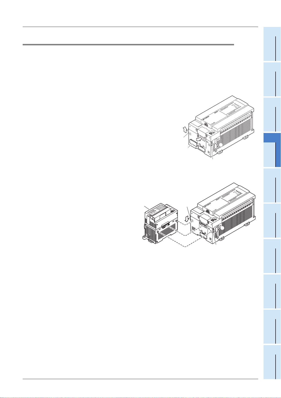
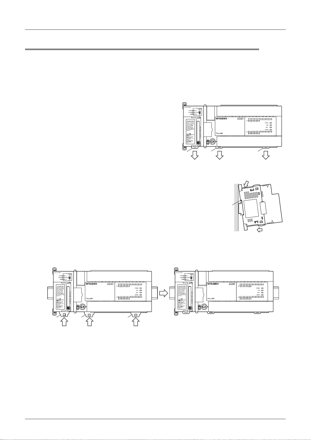
4.1 CF-ADP Connection
An expansion board should be installed before connection of the CF-ADP. An expansion board is not required
when the CF-ADP is connected to a FX
This section explains an example where the CF-ADP is connected to a FX
PLC, refer to the respective PLC manual.
3UC(D, DSS) PLC.
1 Remove the special adapter connector cover
(A in the figure on the right) from the expansion
board.
It is assumed that an expansion board has been installed in
advance. For the expansion board installation method, refer
to the respective PLC manual.
→ Refer to the FX3U Hardware Edition
→ Refer to the FX
3UC Hardware Edition
2 Slide the special adapter connecting hooks
(B in the figure on the right) of the main unit
upwards.
4.1 CF-ADP Connection
3U PLC. For connection to another
→ Refer to the FX
→ Refer to the FX
2
1
B
A
3U Hardware Edition
3UC Hardware Edition
2
B
4 Installation
Configuration
1
Introduction
2
Specification
3
System
4
Installation
3 Connect the CF-ADP (C in the
figure on the right) to the main
unit as shown in the figure on the
right.
4 Slide the special adapter
connecting hooks (B in the figure
on the right) of the main unit
downwards to secure the CF-ADP
(C in the figure on the right).
5
Wiring
C
B
4
3
3
3
4
B
6
Functions
7
Before
Programming
8
CF-ADP Applied
Instructions
Explanation
23
9
Program
Examples
10
Troubleshooting
Page 30
FX3U-CF-ADP User's Manual
4.2 DIN rail mounting
The CF-ADP may be mounted on a 35mm (1.38") wide DIN46277 (DIN rail).
Connect the CF-ADP to the PLC main unit before attaching the CF-ADP to a DIN rail.
This section explains an example where the CF-ADP is connected to a FX
method for other PLCs, refer to the respective PLC manual.
1 Push out all DIN rail mounting hooks (A
in the figure on the right).
It is assumed that the CF-ADP has been connected
in advance. For the CF-ADP connection method,
refer to the following.
→ Refer to Section 4.1.
3U PLC. For the DIN rail mounting
→ Refer to the FX
→ Refer to the FX
4 Installation
4.2 DIN rail mounting
3U Hardware Edition
3UC Hardware Edition
A
A
2 Fit the upper edge (B in the figure on the right) of the DIN
A
2
111
rail mounting groove onto the DIN rail.
3 Push the product onto the DIN rail.
B
3
4 Lock the DIN rail mounting hooks (A in the following figure) while pressing
the PLC against the DIN rail.
24
A
A
4
4
A
4
Page 31

FX3U-CF-ADP User's Manual
4.3 Direct mounting
When the CF-ADP is connected to a FX3U PLC, the CF-ADP may be mounted directly on a pan el surface
using screws. The direct mounting method is not available when the CF-ADP is connected to a FX
Connect the CF-ADP to the main unit before attaching it to the panel surface.
For mounting, refer to the following manual.
1 Create mounting holes in the
mounting surface according to the
external dimensions diagram.
2 Fit the CF-ADP to the mounting
holes and tighten with M4 screws
(A in the figure on the right).
Also fit the main unit to the mounting holes
and tighten with M4 screws. For the main unit
connection method, refer to the following.
→ Refer to the FX3U Hardware Edition
It is assumed that the CF-ADP has been
connected in advance.
For the CF-ADP connection method, refer to
the following.
→ Refer to Section 4.1.
→ Refer to the FX
A
A
4 Installation
4.3 Direct mounting
3UC PLC.
3U Hardware Edition
Configuration
1
Introduction
2
Specification
3
System
4
Installation
5
Wiring
For the screw positions and number of screws in the CF-ADP, refer to the dimensional outline
drawing as follows.
→ Refer to Section 1.2.
For the screw positions and number of screws in the main unit, refer to the following manual.
→ Refer to the FX3U Hardware Edition
6
Functions
7
Before
Programming
8
CF-ADP Applied
Instructions
Explanation
9
Program
Examples
25
10
Troubleshooting
Page 32

FX3U-CF-ADP User's Manual
4.4 Inserting and Removal Procedures
4.4.1 Inserting the CompactFlashTM card
The CompactFlashTM card can be inserted when the CF-ADP is power off.
When the power supply of CF-ADP is ON and it inserts the CompactFlash
the following procedures.
4 Installation
4.4 Inserting and Removal Procedures
TM
card, make sure to perform of
1 Set the CF card ACCESS switch to OFF (A in
the figure on the right) in the CF-ADP . Confirm
that the POWER LED is lit.
2 Open the CF card cover.
TM
Insert the CompactFlash
card slot with the front side (side B in the
figure on the right) facing the right side of the
CF-ADP until the EJECT button (side C in the
figure on the right) pops out.
card into the CF
CompactFlash
card
CF-ADP
TM
(A)(D)
3 Confirm that the CF card ACCESS LED
is lit or flickers and turns OFF, and then the
SLOT LED (D in the figure on the right) turns
ON.
4 Close the CF card cover.
Set the CF card ACCESS switch to ON.
26
Front
side (B)
EJECT button (C)
Page 33

FX3U-CF-ADP User's Manual
4.4.2 Removing the CompactFlashTM card
The CompactFlashTM card can be removed when the CF-ADP is power off.
When the power supply of CF-ADP is ON and it removes the CompactFlash
the following procedures.
1 Set the CF card ACCESS switch of the CF-
ADP to OFF (A in the figure on the right), and
make sure that the CF card ACCESS LED and
BUFFER LED (B in the figure on the right)
both turn off.
(When the CF card ACCESS LED turns off, the
TM
CompactFlash
when the CF-ADP is powering on.)
When the CF card ACCESS LED is lit or flickering, do not
removing the CompactFlash card or power off the CF-ADP.
Doing so may cause data corruption or malfunction.
card can be removed even
TM
4 Installation
4.4 Inserting and Removal Procedures
TM
card, make sure to perform of
(A)(B)
Configuration
1
Introduction
2
Specification
3
System
4
Installation
2 Open the CF card cover.
Push the EJECT button (C in the figure on the
right) of the CF-ADP to push out the
TM
CompactFlash
When ejecting the CompactFlash card, support it by hand
since it may pop out.
Failure to do so may cause the CompactFlash card to fall
leading to failure or damage of the card.
card and remove it.
TM
TM
CF-ADP
CompactFlashTM
card
Push
EJECT button (C)
5
Wiring
6
Functions
7
Before
Programming
8
CF-ADP Applied
Instructions
Explanation
27
9
Program
Examples
10
Troubleshooting
Page 34

FX3U-CF-ADP User's Manual
5. Wiring
DESIGN PRECAUTIONS
• Make sure to include the following safety circuits outside the PLC to ensure safe system operation even during external power supply
problems or PLC failure.
Otherwise, malfunctions may caus e serious accidents.
1) Above all, the followi ng components should be included: an emerg ency stop circuit, a protection circuit , an interlock circuit for
opposite movements (such as normal vs. r everse r otation), and an int erlock cir cuit (to pr event da mage to the e quipment at the
upper and lower positioning limits).
2) Note that when the PLC main unit detects an error during self diagnosis, such as a watchdog timer error, all outputs are turned off.
Also, when an error th at ca nnot be detec ted by t he PLC main u nit occ urs i n an inp ut/ out put c ontrol bloc k, outp ut cont rol ma y be
disabled.External circuits and mechanisms should be designed to ensure safe machinery operation in such cases.
DESIGN PRECAUTIONS
• Observe the following items. F ailure to do so may cause i ncorrect data-writing th rough noise to the PLC and result in PLC failure,
machine damage or other accident.
1) Do not bundle the control line together with or lay it close to the main circuit or power line. As a guideline, lay the control line at
least 100mm (3.94") or more away from the main circuit or power line.
Noise may cause malfunctions.
2) Ground the shield wire or shield of a shielded cable. Do not use common grounding with heavy electrical systems
• During access (ACCESS LED is l it or fli ckering) to Compac tFlashTM card, do not remove the CompactFlashTM card or power off the
CF-ADP.
Failure to do so may cause CompactFlashTM card failures or malfunctions.
• If the power is turned OFF wh ile the Compa ctFlashTM card is being accessed (ACCE SS LED is lit or flicke ring), the buffere d data is
erased. Also files or CompactFlashTM card itself may be damaged. Do not turn the power OFF while the ACCESS LED is lit or
flickering.
• Do not apply excessive pressu re to the power supply cable or power supply connector.
Excessive pressure may cause da mage or error.
5 Wiring
WIRING PRECAUTIONS
• Make sure to cut off all phases of the power supply externally bef ore attempting wiring work.
Failure to do so may cause electric shock or damage to the product.
WIRING PRECAUTIONS
• Connect the DC power supply wiring to the dedicated terminal described in this manual.
If an AC power supply is connected to a DC input/output terminal or DC power supply terminal, the PLC will burn out.
• Connect the DC power supply wiring to the dedicated connector descri bed in this manual.
If an AC power supply is connected to a DC power supply connecto r, the PLC will bu rn out .
• When drilling screw holes or wiring, make sure that cutting and wiri ng debris do not enter the ventilation slits.
Failure to do so may cause fire, equipment failures or malfunctions.
STARTUP AND MAINTENANCE
PRECAUTIONS
• Make sure to connect the battery correctly. Do not charge, disassemble, heat, short-circuit, or expose the battery to fire.
Doing so may rupture or ignite it.
• Do not touch any terminal while the PLC's power is on.
Doing so may cause electric shock or malfunctions.
• Before modifying or disrup ting the program in operation or runni ng the PLC, careful ly read through th is manual and the associated
manuals and ensure the safety of the operation.
An operation error may damage the machinery or cause accidents.
28
Page 35

FX3U-CF-ADP User's Manual
STARTUP AND MAINTENANCE
PRECAUTIONS
• Do not disassemble or modify the PLC.
Doing so may cause fire, equipment failures, or malfunctions.
For repair, contact your local Mitsubishi Electric distributor.
• Turn off the power to the PLC befor e attaching or detaching the foll owing devices.
Failure to do so may cause device failures or malfunctions.
- Peripheral devices, display modules, expansion boa rds and special adapters
- I/O extension units/blocks, FX Series terminal block and the special function units/blocks
- Battery and memory cassette
5 Wiring
5.1 Which Power Supply Cable to Use
1
Introduction
2
Specification
5.1 Which Power Supply Cable to Use
The cable for connecting the CF-ADP power supply connector with the power supply is described here.
5.1.1 Power supply cable
A dedicated power supply cable offered as an accessory of the CF-ADP is available.
Model name Length Remarks
FX2NC-100MPCB 1m (3’3") Accessory of CF-ADP
5.1.2 Preparing the power cable by yourself
To prepare the power cable by yourself, use the following wiring material and connector type.
Model name Specifications/model name
Wire size
Crimp terminal 1602-0069 (Manufactured by Molex Incorporated)
Housing 51030-0330 (Manufactured by Molex Incorporated)
AWG 24(0.2mm2)
Configuration
3
System
4
Installation
5
Wiring
6
Functions
7
Before
Programming
8
CF-ADP Applied
Instructions
Explanation
9
Program
Examples
10
Troubleshooting
29
Page 36

FX3U-CF-ADP User's Manual
5.2 Power Supply Wiring
5.2.1 Power supply wiring
Grounding
CF-ADP
Expansion
board
FX
3U
PLC
[Main unit]
CF-ADP
Expansion
*1
board
5 Wiring
5.2 Power Supply Wiring
FX
3UC
PLC
[Main unit]
Power connector
GreenRedBlack
24+24-
Stabilized
power supply
24V DC
*1. The expansion board is required when connecting with the FX3UC-32MT-LT PLC.
Power-on/off timing
The CF-ADP power supply should be turned ON simultaneously with or before the power supply of the PLC
main unit. Before turning the power OFF, ensure the safety of the system and then simultaneously turn the
main unit, CF-ADP, and other extension equipment (the special extension equipment is included) OFF.
For details, refer to the respective PLC manual.
5.3 Grounding
Ground the cables as follows
• The grounding resistance should be 100 or less.
• Independent grounding should be established whenever possible.
Independent grounding should be performed for best results.
When independent grounding is not configured, perform "shared grounding" as shown in the following
figure.
For details, refer to the respective PLC manual.
Grounding
Power connector
GreenRedBlack
24+24-
Grounding
Stabilized
power supply
24V DC
→ Refer to the FX
→ Refer to the FX
→ Refer to the FX
→ Refer to the FX
Grounding
3U Hardware Edition
3UC Hardware Edition
3U Hardware Edition
3UC Hardware Edition
30
CF-ADP
Independent grounding
Best condition
Other
equipment
CF-ADP
Shared grounding
Good condition
Other
equipment
CF-ADP
Common grounding
Not allowed
Other
equipment
• The grounding point should be close to the CF-ADP, and all grounding wires should be as short as
possible.
Page 37

FX3U-CF-ADP User's Manual
5.4 Power OFF procedure
Make sure to perform either of the following procedures when turning OFF the power of the CF-ADP.
• Power OFF procedure using the CF card ACCESS switch
• Power OFF procedure using the applied instruction for the CF-ADP
5.4.1 Power OFF procedure using the CF card ACCESS switch
1 Set the main unit to the STOP mode, or set the
applied instruction for the CF-ADP to the unactuated
status.
2 Turn OFF the CF card ACCESS switch, and then
confirm that the ACCESS LED (A in the figure on the
right) and BUFFER LED (B in the figure on the right)
are completely OFF.
5 Wiring
5.4 Power OFF procedure
→ Refer to Subsection 5.4.1
→ Refer to Subsection 5.4.2
(A)(B)
Configuration
1
Introduction
2
Specification
3
System
4
Installation
3 Turn the power of the CF-ADP OFF.
5.4.2 Power OFF procedure using the applied instruction for the CF-ADP
1 Execute the FLCMD instruction to
TM
unmount the CompactFlash
card.
2 Confirm that the FLCMD instruction
is completed normally.
1.Execute the FLCMD instruction,
X000
M0
2.Confirm that the FLCMD instruction is normally completed.
3.Turn the power of the CF-ADP OFF.
FNC304
FLCMD
3 Turn the power of the CF-ADP OFF.
M8029
Execution
completion
If the FLCMD instruction is abnormally completed,
do not turn the power of the CF-ADP OFF .
M8329
Abnormal
end
5
Wiring
6
Functions
M0SET
K1H200
M0RST
Y0SET
M0RST
Y1SET
7
Before
Programming
8
CF-ADP Applied
Instructions
Explanation
9
Program
Examples
5.4.3 Caution on power OFF
If the power is turned OFF while the CompactFlashTM card is being accessed (ACCESS LED is lit or
flickering), the buffered data is erased. Also files or CompactFlash
Do not turn the power OFF while the ACCESS LED is lit or flickering.
TM
card itself may be damaged.
31
10
Troubleshooting
Page 38

FX3U-CF-ADP User's Manual
5.5 Connection of the power supply cable
The CF-ADP receives and supplies power through the built-in dedicated power connector.
5.5.1 Connection/removal of the power supply cable
• Connection
Connect the power supply cable after confirming the connector direction.
5 Wiring
5.5 Connection of the power supply cable
• Removal
Squeeze the power cable connector at "a" and disconnect it in the direction of the arrow.
a
Press here
32
Page 39

FX3U-CF-ADP User's Manual
6. Functions
6.1 Details of functions
The user can perform the following procedures for CompactFlashTM cards using applied instructions for the
CF-ADP.
• Creating FIFO function files inside the CompactFlash
(Only one pattern is available for FIFO function files. Multiple FIFO function files are created automatically
with a predetermined file name. If the created FIFO function files exceed the allowable capacity, old files
are deleted. The FIFO function is executed in units of files.)
• Creating files inside the CompactFlash
(Up to 63 files can be created.)
• Deleting specified files stored in the CompactFlash
• Writing bit data, word data, double-word data, floating point data and character string data to a specified
file stored in the CompactFlash
Data can be written to the CompactFlash
- Data is directly written to the CompactFlash
points can be written to one line.
- Data is collected in the internal buffer. When the internal buffer becomes full, data is written to the
CompactFlash
• Forcibly writing data of a specified file stored in the internal buffer to the CompactFlash
• Reading the number from the final line in a specified file stored in the CompactFlash
• Reading the data from a specified line in a specified file stored in the CompactFlash
(Up to 254 data points can be read from one line.)
• Writing the data name.
(Up to 254 data points names can be written.)
• Formatting the CompactFlash
• Sending a mount command to the CompactFlash
• Sending an unmount command to the CompactFlash
TM
card. Up to 254 data points can be written to one line.
TM
TM
card.
card.
TM
card.
TM
card.
TM
card.
TM
card using the following two methods:
TM
card without using the internal buffer. Up to 254 data
TM
card.
TM
card.
6 Functions
6.1 Details of functions
TM
card.
TM
card.
TM
card.
Configuration
Programming
1
Introduction
2
Specification
3
System
4
Installation
5
Wiring
6
Functions
7
Before
33
8
CF-ADP Applied
Instructions
Explanation
9
Program
Examples
10
Troubleshooting
Page 40

FX3U-CF-ADP User's Manual
6.2 Status information
The user can read the following status information using applied instructions for the CF-ADP.
• Detecting that a CompactFlash
• Detecting that the CompactFlash
• Detecting errors that have occurred in the CF-ADP.
• Reading error codes and details of error codes of the CF-ADP.
• Data capacity of the CompactFlash
1(MB)=1024(kB), 1(GB)=1024(MB)=1,048,576(kB)
Capacity less than 1 kB is regarded as "1 kB".
• Used space of the CompactFlash
1(MB)=1024(kB), 1(GB)=1024(MB)=1,048,576(kB)
Capacity less than 1 kB is regarded as "1 kB".
• Free space of the CompactFlash
1(MB)=1024(kB), 1(GB)=1024(MB)=1,048,576(kB)
Capacity less than 1 kB is regarded as "1 kB".
• File ID list.
(File ID: The file name is associated with the file ID, and the file ID is used in sequence programs (applied
instructions).)
• CF-ADP version information.
TM
card is mounted.
TM
card is full.
TM
card. (Unit: kB)
TM
card. (Unit: kB)
TM
card. (Unit: kB)
6 Functions
6.2 Status information
34
Page 41

FX3U-CF-ADP User's Manual
7. Before Programming
7 Before Programming
7.1 File format available in the CF-ADP
1
Introduction
This chapter describes several items that should be known before programming.
• File format available in the CF-ADP
• Files created by the user
• Characters available in files
• Data size calculation
• Data writing destination
•File ID
• FIFO file
• Directory structure
• Date/time setting
• General rules for applied instructions
7.1 File format available in the CF-ADP
Files in the "csv" format are available in the CF-ADP.
Files are created by the CF-ADP and by the user.
7.1.1 Files created by the CF-ADP
Files in the "csv" format created by the CF-ADP are as follows. The CF-ADP can read and write files whose
data is separated by comma (,), and line-feed by "CR + LF".
One line can store up to 254 data points.
For characters available in files, refer to Subsection 7.1.3.
Configuration
2
Specification
3
System
4
Installation
5
Wiring
6
Functions
CSV file
(1)
,
,
Index
,
Index
,
Index
,
Index
,
Index
,
Index
,
Index
,
Index
(3) (4) (5) (6) (7) (8)
DATE TIMEIndex
Year/Month/Day
Hour:Minute:Seconds
Year/Month/Day
Hour:Minute:Seconds
Year/Month/Day
Hour:Minute:Seconds
Year/Month/Day
Hour:Minute:Seconds
Year/Month/Day
Hour:Minute:Seconds
Year/Month/Day
Hour:Minute:Seconds
Year/Month/Day
Hour:Minute:Seconds
Year/Month/Day
Hour:Minute:Seconds
Data
,
name
,
,
,
,
,
,
,
,
Data
name
data
data
data
data
data
data
data
data
(2)
Data
,,,,
name
data data LF
,,,,
data data LF
,,,,
data data LF
,,,,
data data LF
,,,,
data data LF
,,,,
data data LF
,,,,
data data LF
,,,,
data data LF
,,,,
Data
name
CR
CRdata
CRdata
CRdata
CRdata
CRdata
CRdata
CRdata
CRdata
LF
7
Before
Programming
8
CF-ADP Applied
Instructions
Explanation
9
Program
Examples
10
Troubleshooting
35
Page 42

FX3U-CF-ADP User's Manual
Contents of files in the "csv" format
No. Contents of data Description Remark
(1) Index,DATE TIME,
(2) Data name
(3) Index
(4) , Comma : 1 character -
year/Month/Day
(5)
Hour:Minute:Seconds
(6) , Comma : 1 character -
(7) data
(8) CR+LF Return code at line end Line feed
When the file name is added, t he Index, date and time are
added automatically.
Character string consisting of up to 32 half-width/full-width
characters
6 digits(*****1 to *32767)
Numeric values should be consecutive, and in ascending
order.
None : Null
yyyy/mm/dd hh:mm:ss : 19 characters
yy/mm/dd hh:mm:ss : 17 characters
dd/mm/yyyy hh:mm:ss : 19 characters
dd/mm/yy hh:mm:ss : 17 characters
mm/dd/yyyy hh:mm:ss : 19 characters
mm/dd/yy hh:mm:ss : 17 characters
hh:mm:ss : 8 characters
Bit : 1 character
Decimal 16-bit : 6 characters
Decimal 32-bit : 11 characters
Hexadecimal 16-bit : 4 characters
Hexadecimal 32-bit : 8 characters
Real numbers(Floating point data)
Exponent type : #.#######E ## : 14 characters
Character string : Varies depending on the character size.
(512 half-width/full-width characters maximum)
7 Before Programming
7.1 File format available in the CF-ADP
-
Refer to Subsection 7.1.3.
Decimal number
" (space)" and "+ (plus)" are used by the
system.
Index values in one file should be different
from each other.
The date and time are updated when data
is additionally written or ove rwritten if the
time stamp is set.
The maximum data size is 16 kB for each
Index.
(One character string should be within 1
kB (512 full-width characters).)
7.1.2 Files created by the user
The contents of files created by the user should be same as files created by the CF-ADP (refer to Subsection
7.1.1).
For characters available in files, refer to Subsection 7.1.3.
For cautions on file creation, refer to the following description.
Caution
• Cautions on creating the 1st column
- Enter the line number in decimal number (1 to 32767 in 6 digits or less).
- Enter the line number consecutively in ascending order.
- Use a line number only once.
- Do not use "+ (plus)" in the line number.
• Cautions on creating the 2nd column (Year/Month/Day Hour:Minute:Seconds).
- Enter the date and time in the specified configuration.
Enter "Index, data, •••, CF+LF" so that the 2nd column area is secured.
• Enter data in the 3rd column and so on. Up to 254 data points can be entered.
• Make sure to separate data with comma (,).
• Use "CR+LF" as the line feed code.
• Cautions on reading data from and writing data to files created by the user
- Associate the file name with the file ID using the FLCRT instruction.
- Files created by the user cannot be overwritten.
• Cautions on reading data from files created by the user
When reading data from a file using the FLRD instruction, match the data type for each saved data point.
Specify the same data type.
If the data types do not agree, data cannot be read normally.
36
Page 43

FX3U-CF-ADP User's Manual
7.1.3 Characters available in files
Following characters are available in files.
Type Available characters Display type
Index '0' to '9' , ' ' (space) , '+' ,
DATE TIME '0' to '9' , '/' , ':' Selectable 1 to 19 digits
Bit '0','1' # 1 digits -
Decimal 16-bit '0' to '9' , '-' , ' ' (space)
Decimal 32-bit '0' to '9' , '-' , ' ' (space)
Hexadecimal
16-bit
Hexadecimal
32-bit
Floating point
data
Character string
'0' to '9','A' to 'F', 'a' to 'f' #### 4 digits -
'0' to '9','A' to 'F', 'a' to 'f' ######## 8 digits -
'0' to '9','E','e','+','-', ' '(space),'.'
Available numeric values
0, 1.1754944E-38 to
3.4028233E+38
Enter "NaN" when data is non
numeric, un-normalized or infi nite.
ASCII characters and
2-byte characters such as shift
JIS characters defined by region
7 Before Programming
7.1 File format available in the CF-ADP
1
Introduction
Number of digits
#####
+#####
#####
-#####
##########
-##########
*7
#.#######E+##
#.#######E-##
-#.#######E+##
-#.#######E-##
NaN
Arbitrary
*3
*4
6 digits
6 digits
11 digits
14 digits
Up to 512 halfwidth/full-width
characters (1024
bytes) per data
point (The entire
amount of data in
one line should be
16 kB or less.)
*1
"+" is used by the system.
The display format is selectable.
Do not add "+" to a positive value.
Add a space.
Do not add "+" to a positive value.
Add a space.
Do not add "+" to a positive value.
Add a space.
Make sure to add "+" or "-" to the exponent
part after "E".
When data is non numeric, u n-normalized
or infinite, a space is added and "NaN" is
set.
Do not use control codes or half-width
symbols in character strings.
Remark
*2
*6
*5
Configuration
2
Specification
3
System
4
Installation
5
Wiring
*1. The data digits are fixed by the data type in the CF-ADP.
Data created using a personal computer cannot be overwritten because the data digits do not match.
*2. A "+" added to the Index value is used by the CF-ADP in the system, and cannot be deleted.
If data is overwritten using a personal computer, etc., a "+" added by the CF-ADP may be deleted and
the CF-ADP may malfunction.
*3. UNICODE characters are not available.
Use characters available in PLCs such as shift JIS characters (which are set by region).
Mitsubishi recommends US-ASCII characters when files are used in an environment that caters to
several languages. Use US-ASCII characters if UNICODE characters are set by region.
Use a personal computer in an environment that is used to create data or program when reading data.
*4. Control codes such as line feed codes (CR and LF), half-width commas (,) and double quotation
marks (") are not available.
*5. Mitsubishi does not recommend the following symbols.
They may be automatically converted by some application software used for data processing.
When using the following symbols, confirm the application software specifications.
Apostrophe ('), caret (^), backslash (\), slash (/), at mark (@) and equal sign (=)
*6. The expression of date and time depends on the setting of the region. Check the used method.
*7. When data is read in floating point format, the data point is converted from the head to the position
which can be read as a numeric value if charact ers outside the floating point s pecification are
contained in the data.
6
Functions
7
Before
Programming
8
CF-ADP Applied
Instructions
Explanation
9
Program
Examples
37
10
Troubleshooting
Page 44

FX3U-CF-ADP User's Manual
7.1.4 Data size calculation
When calculating the data size, use the following formula in accordance with the byte count shown in the
table below.
Contents of data Used characters
6 digits (expressed in a decimal nu mber from "1" to
Index
, 1 character 1 byte - C o mma
year/Month/Day
Hour:Minute:Seconds
, 1 character 1 byte - C o mma
data
CR+LF Retur n code at line end 2 bytes - Line feed
"32767")
Space is put in for unused digits.
Plus signs (+) are used in some systems.
None 0 byte
yyyy/mm/dd hh:mm:ss 19 bytes
yy/mm/dd hh:mm:ss 17 bytes
dd/mm/yyyy hh:mm:ss 19 bytes
dd/mm/yy hh:mm:ss 17 bytes
mm/dd/yyyy hh:mm:ss 19 bytes
mm/dd/yy hh:mm:ss 17 bytes
hh:mm:ss 8 bytes
Bit 1 byte
Decimal 16-bit 6 bytes
Decimal 32-bit 11 bytes
Hexadecimal 16-bit 4 bytes
Hexadecimal 32-bit 8 bytes
Real numbers(Floating point data)
Exponent expression type= #.#######E ##
Character string
(512 half-width/full-width characters maximum)
7 Before Programming
7.1 File format available in the CF-ADP
Number of
bytes
6 bytes - Decimal 6 digits
14 bytes
Character string
size
(1024 bytes
maximum)
Symbol Remark
The expression of date and
time depends on the setting
(a)
of the region.
Check the used method.
(b) -
Calculation formula for the byte count that can be written at one time Number of data points : n (n 254)
Calculation formula
Written byte count = 9+(a)+ (1+(b))
n
1
Example of the maximum numeric value (When there are 254 floating point data points)
Written byte count = 9+19+ {(1+14)} (Sum of 254 data points) = 3838 byte 3.75kB
254
1
Example of character string
Written byte count = 9+19+ {(1+(b))} (Sum of "n" character strings) 16kB
n
1
Caution
• When overwriting data, match the data type and byte count in the line.
• Data is not overwritten or read normally if the data type or byte count is different.
38
Page 45

FX3U-CF-ADP User's Manual
7.1.5 Data writing destination
Data can be written to two destinations, the CompactFlashTM card and the internal buffer inside the CF-ADP.
7 Before Programming
7.1 File format available in the CF-ADP
1
Introduction
CF-ADP
2)
Internal buffer
inside CF-ADP
1)
CompactFlash
card
TM
Writing
destination
Writing
destination
Main unit
Sequence
program
1. When data is written to the CompactFlashTM card
When the CompactFlashTM card is specified as the writing destination in the applied instruction for the CFADP, data is directly written to the CompactFlash
Because data is written to the CompactFlash
pay attention to the number of times data is written to the CompactFlash
For example, if data is written to the CompactFlash
approximately 2 months.
Even if the power is turned OFF after data is written normally, the written data is not cleared.
TM
card.
TM
card every time the instruction is executed, the user should
TM
card.
TM
card every minute, data is written 100,000 times in
2. When data is written to the internal buffer inside the CF-ADP
When the Internal buffer inside the CF-ADP is specified as the writing destination in the applied instruction for
the CF-ADP, data is written to the internal buffer inside the CF-ADP. This type of writing is not counted as a
TM
data write to the CompactFlash
CompactFlash
because data is cleared in the following cases.
Data is cleared at the following times, and data is written from the internal buffer inside the CF-ADP to the
CompactFlash
TM
card is counted as a data write to the CompactFlashTM card. However, attention is required
TM
card at the following times.
card. Data writing from the buffer inside the CF-ADP to the
Configuration
2
Specification
3
System
4
Installation
5
Wiring
6
Functions
Times when the internal buffer inside the CF-ADP is cleared
- When the file deletion command or file formatting command is executed
TM
- When the CompactFlash
- When the power is turned OFF using any procedure other than the specified power OFF procedure
Times when data is written from the internal buffer inside the CF-ADP to the CompactFlash
- When data to be buffered exceeds the capacity of the internal buffer inside the CF-ADP
- When the buffer force write command is executed
- When data writing is executed for a buffered file ID with the CompactFlash
writing destination
- When the CF card ACCESS switch is set from ON to OFF
- When an applied instruction to unmount the CompactFlash
- When the Index is returned to the head among buffered data (ring buffer)
Or when data writing is executed for the specified maximum number of lines if "Stops execution" is
selected as the processing to be executed when the maximum number of lines specified during file
creation is reached
- When the overwrite applied instruction is executed while data is buffered
card is pulled out
TM
card is executed
TM
card specified as the
TM
card
7
Before
Programming
8
CF-ADP Applied
Instructions
Explanation
9
Program
Examples
10
Troubleshooting
39
Page 46

FX3U-CF-ADP User's Manual
7.1.6 File ID
Applied instructions for the CF-ADP use the file ID for specifying files. Accordingly, the file name saved in the
CompactFlash
When a file whose file ID is "1" and file name is "TEST_01.CSV" is created using the file creation program
shown below, the file ID and file name are associated with each other as shown in "Example 1" in the ID table
image. After each file is created, the user should use the file ID for specifying the file, instead of using the file
name.
File creation program
TM
card is associated with the file ID, and controlled by the ID table.
7 Before Programming
7.1 File format available in the CF-ADP
X000
M0 M8404
CF-ADP
unit ready
M8405
CF card is
mounted
FNC300
FLCRT
M8329
Abnormal
end
M8029
Execution
completion
FNC209
$MOV
K1
File
ID
FNC 12
MOV
FNC 12
MOV
FNC 12
MOV
FNC 12
MOV
File
name
M0SET
D0"TEST_01"
D10K*
D11K*
D12K*
D13K*
K1D10D0
M0RST
M0RST
File name
The file name is set to
"TEST_01.CSV".
The file is created.
40
ID table image
Example
1
File ID File neme
File ID=0
File ID=1
File ID=2
File ID=61
File ID=62
File ID=63
FILE****.CSV
TEST_01.CSV
********.CSV
********.CSV
********.CSV
********.CSV
"****" represents a numeric value from 0000 to 0999.
"FILE" in the file name is fixed.
The file ID "1" is associated with the file name
"TEST_01.CSV".
"*******" represents the file name created by the user.
Page 47

FX3U-CF-ADP User's Manual
7.1.7 FIFO file
When the file ID is set to "K0", the CF-ADP creates FIFO files.
The CF-ADP creates multiple FIFO files, and executes FIFO (first in, first out) in units of files for the CF-ADP.
With the FIFO function, the CF-ADP keeps the latest d ata, an d de let es old da ta so t hat the to tal ca pacity of
FIFO files and other files do not exceed the specified CompactFlash
• When created files does not exceed the CompactFlash
use ratio)
The CF-ADP creates files whose name consists of a consecutive number in ascending order in the way
"FILE0000.CSV, FILE0001.CSV ••• FILE0999.CSV". When the file name reaches "FILE0999.CSV", the
CF-ADP deletes the oldest existing file "FILE0000.CSV", and creates a new file "FILE0000.CSV".
FIFO file creation
7 Before Programming
7.1 File format available in the CF-ADP
TM
card use ratio.
TM
card capacity (specified CompactFlashTM card
Configuration
1
Introduction
2
Specification
3
System
FIFO file
FILE0000.CSV
FIFO file
FILE0000.CSV
FILE0001.CSV
FIFO file
FILE0000.CSV
FILE0001.CSV
FILE0002.CSV
• When created files exceed the CompactFlash
FIFO file
FILE0000.CSV
FILE0001.CSV
FILE0002.CSV
FILE0998.CSV
TM
card capacity (specified CompactFlashTM card use ratio)
FIFO file
FILE0000.CSV
FILE0001.CSV
FILE0002.CSV
FILE0998.CSV
FILE0999.CSV
FIFO file
FILE0000.CSV
FILE0001.CSV
FILE0002.CSV
FILE0998.CSV
FILE0999.CSV
The CF-ADP creates files whose name consists of a consecutive number in ascending order starting from
"FILE0000.CSV" within the CompactFlash
TM
card capacity. When created files reach the CompactFlashTM
card capacity, the CF-ADP deletes the oldest existing file, and creates a new file.
FIFO file creation
FIFO file
FILE0000.CSV
FIFO file
FILE0000.CSV
FILE0001.CSV
FIFO file
FILE0000.CSV
FILE0001.CSV
FIFO file
FILE0000.CSV
Delete
FILE0001.CSV
FIFO file
FILE0001.CSV
Delete
FILE0002.CSV
FIFO file
FILE0002.CSV
Delete
FILE0003.CSV
Programming
4
Installation
5
Wiring
6
Functions
7
Before
FILE0002.CSV
FILE0002.CSV
FILE0003.CSV
Caution
1) The CF-ADP can create up to 1000 files
However, make sure that created files do not exceed the CompactFlash
CompactFlash
TM
card use ratio).
2) The file name is fixed to "FILE0000.CSV" to "FILE0999.CSV".
FILE0003.CSV
FILE0004.CSV
TM
card capacity (specified
FILE0004.CSV
FILE0005.CSV
41
8
CF-ADP Applied
Instructions
Explanation
9
Program
Examples
10
Troubleshooting
Page 48

FX3U-CF-ADP User's Manual
7.2 Directory structure
The following directory is created inside the CompactFlashTM card.
• In the case of a normal file
The directory "\FX3U_CF\DATA\." is created inside the CompactFlash
The following data is stored in the directory.
TM
7 Before Programming
7.2 Directory structure
card.
Root \FX3U_CF\DATA\. User data.CSV(Normal data file created by the user)
Directory
IDTABLE.SYS
Various log
M_PF.log
POWD.cnt
EPOWD.log
CF_UM.log
BPD.cnt
System files created automatically.
Do not edit them.
• In the case of a FIFO file
The directory "\FX3U_CF\DATA\FIFO\." is created inside the CompactFlash
TM
The following data is stored in the directory.
Root \FX3U_CF\DATA\FIFO\.
Directory
IDTABLE.SYS
Various log
M_PF.log
POWD.cnt
EPOWD.log
CF_UM.log
BPD.cnt
User data.CSV(FIFO file)
System files created automatically.
Do not edit them.
card.
7.3 Date/time setting
The clock function of the main unit is used for the date and time used in the CF-ADP.
Make sure to set the clock data in the main unit before using the CF-ADP.
The available clock data range is from "00:00:00 on January 1, 2008" to "23:59:59 on December 31, 2079".
If the user sets the date and time outside this range, "00:00:00 on January 1, 2008" is actually set instead.
For the clock data setting method in the main unit, refer to the following manual.
→ Refer to the programming manual.
42
Page 49

FX3U-CF-ADP User's Manual
7.4 General Rules for Applied Instructions
7.4.1 Expression and operation type of applied instructions
7 Before Programming
7.4 General Rules for Applied Instructions
1
Introduction
Instruction and operands
- Function numbers (FNC00 - FNC ) and symbols (mnemonic codes) are assigned to the applied
instructions of the PLC. For example, a symbol of "FLWR" (Data write) is assigned to FNC302.
- Some applied instructions consist of the instruction area only, but many applied instructions consist of
the instruction area and the operand.
Command
input
S
D
m, n : The operands not corresponding to source and destination are indicated as "m" and "n".
- Regarding program steps, the instruction area for each applied instruction is 1 step. The operand of
each applied instruction, however, has 2 or 4 steps depending on the number of bits (16 or 32 bits).
Devices for operands
- Bit devices X, Y, M, and S can be used for the operands, depending on the function.
- Combination of these bit devices, such as KnX, KnY, KnM, and KnS, can be used for numeric data.
- Current value registers, such as data registers D, timers T, and counters C, can be used.
- A data register D consists of 16-bit. Two consecutive data registers (2 points) are used for 32-bit data.
For example, if data register D0 is specified for the operand of a 32-bit instruction, D1 and D0 will be
used for 32-bit data (D1 for the 16 high-order bits, and D0 for the 16 low-order bits).
If current value registers T and C are used as general data registers, they will behave the same way as
data registers.
Each 32-bit counter (C200 to C255), however, can use 32-bit data without combining two counters.
These counters, however, cannot be specified as the operands of 16-bit instructions.
FNC302
FLWR
: An operand that will not be affected by the execution of the instruction is referred to as a
source. This symbol represents a source.
If the operand device number can be modified by an index register, " " will be added, and
the S will be modified to . If there are two or more sources, the modified sources will
become , , and so on.
: An operand that will be affected by the execution of the instruction is referred to as a
destination. This symbol represents a destination.
If the device numbers can be indexed by index registers, and if there are two or more
destinations, the modified destinations will become , , and so on.
If the device number can be indexed by index registers, and if there are two or mo re
operands, the modified operands will become m1 , m2 , n1 , n2 , and so on.
S
1
S1 S2
2
Specification
3
System
Configuration
2
S
S
3
D
nS
D1 D2
→ Refer to the programming manual.
4
Installation
5
Wiring
6
Functions
7
Before
Programming
8
CF-ADP Applied
Instructions
Explanation
43
9
Program
Examples
10
Troubleshooting
Page 50

7 Before Programming
FX3U-CF-ADP User's Manual
7.4 General Rules for Applied Instructions
7.4.2 Programming using "Instruction execution complete" flag and "Instruction execution abnormal end" flag
1) If two or more CF-ADP instructions are used in a program, the "Instruction execution complete" flag
(M8029)
each instruction. However, if the "Instruction execution complete" flag (M8029) and "Instruction execution
abnormal end" flag (M8329) are used together for a progra m, it is difficult to determine which instruction
turns them ON/OFF and the "Instruction execution complete" flag (M8029) will not be turned on for the
intended instruction.
*1. For an applied instruction for the CF-ADP, the instruction execute complete flag (M8029) indicates
Good
example:
*1
or "Instruction execution abnormal end" flag (M8329) will be turned on or off after execution of
that the instruction has been completed normally.
→ To use a CF-ADP instructions at a position other than just below the instruction, refer to the
example shown on the next page.
Bad
example:
The M8029 will function
as the "instruction
execution complete" flag
of FLCRT instruction.
The M8029 will function
as the "instruction
execution complete"
flag of FLWR instruction.
The M8029 will function
as the "instruction
execution complete" flag
of the lower FLSTRD
instruction.
The M8029 will function
as the "instruction
execution complete" flag
of the lower DSW
instruction.
The M8029 will function
as the "instruction
execution complete" flag
of the upper FLSTRD
instruction.
M0
FNC300
FLCRT
K1 D0 D10 K1
M8029
Completion
of instruction
execution
RST
M8329
Abnormal
completion of
instruction execution
M1
FNC302
FLWR
RST
K1 D20 D30
M8029
Completion
of instruction
execution
RST
M8329
Abnormal
completion of
instruction execution
RST
M8029
Completion of
instruction
execution
M8000
FNC 72
DSW
X000
SET
M0
FNC305
FLSTRD
M8029
FNC 22
MUL
Completion of instruction execution
M1
FNC305
FLSTRD
RST
X10 Y10 D0
M0
H200 D100 K1
D0 K10 D20
H300 D200 K1
M0
M0
D40
M1
M1
Program for upper FLSTRD
M0
instruction
K1
Upper FLSTRD instruction
Program for DSW
instruction
Lower FLSTRD instruction
K1
44
Page 51

FX3U-CF-ADP User's Manual
2) To use at a position other than just below the CF-ADP instructions.
If two or more CF-ADP instructions are used in a p rogram, the "Instruction execut ion complete" flag
(M8029) and "Instruction execution abnormal end" flag (M8329) will be turned on or off after execution of
each instruction.
If it is necessary to use the "Instruction execution complete" flag (M8029) or "Instruction ex ecution
abnormal end" flag (M8329) at a point other than just below the instruction, turn on or off another bit
device just below the instruction, and use the contact as the command contact.
7 Before Programming
7.4 General Rules for Applied Instructions
1
Introduction
2
Specification
Switches "instruction
execution complete"
flag of the DSW
instruction from M8029
to M100.
Switches the
"instruction execution
complete" flag of the
FLCRT instruction from
M8029 to M200.
M8000
M0
Completion
of instruction
Functions as the instruction
execution complete flag of
the DSW instruction.
M100
Functions as the instruction
execution complete flag of the
FLCRT instruction.
M200
FNC 72
M8029
Completion
of instruction
execution
FNC300
FLCRT
M8029
execution
DSW
X10 Y10 D0 K1
K1 D0 D10
FNC 22
MUL
M100
K1
RST
D0 K10 D20
M0
M200
Y000
Configuration
3
System
4
Installation
5
Wiring
6
Functions
7
Before
Programming
8
CF-ADP Applied
Instructions
Explanation
9
Program
Examples
10
Troubleshooting
45
Page 52

8 CF-ADP Applied Instructions Explanation
FX3U-CF-ADP User's Manual
8. CF-ADP Applied Instructions Explanation
This chapter explains applied instructions for the CF-ADP.
8.1 CF-ADP Instructions types
The PLC and the CF-ADP transfer data to each other using applied instructions for the CF-ADP.
Six applied instructions are provided for purpose including file creation, data writing and data reading.
• List of applied instructions for the CF-ADP
FNC No. instruction Description Control direction
300 FLCRT File create / check
301 FLDEL File delete / CF card format
302 FLWR Data write
303 FLRD Data read
304 FLCMD FX3U-CF-ADP command
305 FLSTRD FX3U-CF-ADP status read
PLC CF-ADP
PLC CF-ADP
PLC CF-ADP
PLC CF-ADP
PLC CF-ADP
PLC CF-ADP
8.1 CF-ADP Instructions types
Detailed
explanation
Section 8.3
Section 8.4
Section 8.5
Section 8.6
Section 8.7
Section 8.8
8.2 Common Items in CF-ADP Instructions
8.2.1 Function and operation
1. Processing start timing
When the command input turns from OFF to ON, the PLC starts processing for the CF-ADP.
If the command input turns OFF during processing for the CF-ADP, execution of the instruction is cancelled
and the instruction is terminated abnormally.
If the command input remains ON, the PLC executes processing repeatedly.
2. Cautions on programming
For processing for the CF-ADP, keep ON the command input for an applied instruction for the CF-ADP ON
until processing has been completed.
Make such a program that the command input is set to OFF using the instruction executing complete flag
(M8029) after all processing for the CF-ADP are finished.
Program Example
X001
M0
Command
input
M8029
Instruction execution
complete
M8329
Instruction execution
abnormal end
FNC 305
FLSTRD
**
SET M0
** **
RST M0
RST M0
Command is latched
Processing is executed
Command is reset
Command is reset
3. Instruction execution complete flag (M8029)
When processing for the CF-ADP has been completed normally, the instruction execute complet e flag
(M8029) turns ON, and remains ON for one scan.
46
Page 53

FX3U-CF-ADP User's Manual
4. Operation when an error occurrs
When an error occurs, the instruction execution abnormal comple te flag (M832 9) tur ns ON, an d execu tion of
the instruction is aborted.
After that, the error code is stored in the error code storage register, and the error flag turns ON.
The user can check the error code, error code details, and error d etected st ep number using the f ollowing
data registers.
Error code storange device Error code detail storange device
ch1 ch2 ch1 ch2 ch1 ch2
D8418 D8438 D8417 D8437 D8415,D8414 D8435,D8434
8 CF-ADP Applied Instructions Explanation
8.2 Common Items in CF-ADP Instructions
Error detected step number storange
device
1
Introduction
2
Specification
Program Example
X000
Start command
M0
M8329
Abnormal
end
M8029
Execution
completion
FNC 300
FLCRT
8.2.2 Cautions on programming
** **
FNC 12
DMOV
FNC 12
MOV
FNC 12
MOV
SET M0
** K1
RST M0
D8414 D50
D8417 D52
D8418 D53
RST M0
Check the step
number in which the
error occurred in the
ch1.
Check details of the
error occurred in the
ch1.
Check the error code
of the error occurred
in the ch1.
Configuration
3
System
4
Installation
5
Wiring
6
Functions
1. Using a CF-ADP instruction together with another instruction
A CF-ADP instruction cannot be used together with a RS, RS2 instruction or inverter communication
instructions if the RS2 instruction or inverter communication instructions uses the same channel.
2. Caution on when two or more application instructions for the CF-ADP are driven
simultaneously
When two or more application instructions for the CF-ADP are driven simultaneously, after performing from
the application command for the CF-ADP with the smaller step number in a program and completing
instructions execution, the next application instructions for the CF-ADP is executed.
3. Caution on writing during RUN
CF-ADP instruction cannot be written to during RUN mode.
When the user writes an applied instruction for the CF-ADP during RUN mode, execution of the instruction is
canceled.
4. Number of times data is written to the CompactFlashTM card
The number of times data is written to the CompactFlashTM card is limited.
When data is directly written to the CompactFlash
time the instruction is executed. The user should pay rigid attention to the number of times data is written to
the CompactFlash
TM
card.
For example, if data is written to the CompactFlash
approximately 2 months.
TM
card, data is written to the CompactFlashTM card every
TM
card every one minute, data is written 100,000 times in
7
Before
Programming
8
CF-ADP Applied
Instructions
Explanation
9
Program
Examples
10
Troubleshooting
47
Page 54

FX3U-CF-ADP User's Manual
r
8.3 FNC 300 - FLCRT / File create•check
Outline
The FLCRT instruction creates a file inside the CompactFlashTM card mounted in the FX3U-CF-ADP. When
executed after creation of a new file, the FLCRT instruction checks the association with th e file ID, and
evaluates it.
1. Instruction format
FNC 300
FLCRT
16-bit Instruction
9 steps
2. Set data
Operand Type Description Data Type
S1
S2
S3
n Used channel number [contents of setting : K1 = ch1, K2 = ch2] 16-bit binary
File ID (Refer to Subsection 8.3.1) 16-bit binary
File name (Refer to Subsection 8.3.1) Character string
File creation parameter (Refer to Subsection 8.3.1) 16-bit binary
Mnemonic Operation Condition
FLCRT
Continuous
Operation
8 CF-ADP Applied Instructions Explanation
8.3 FNC 300 - FLCRT / File create•check
32-bit Instruction
Mnemonic Operation Condition
3. Applicable devices
Bit Devices Word Devices Others
Operand
Type
S1
S2
S3
n
System User Digit Specification System Us er
XYMTCS
KnX KnY KnM KnS T C D R
D.b
Special
Unit
U\G
Index
V Z Modify K H E
Constant
Real
Number
Explanation of function and operation
1. 16-bit operation (FLCRT)
Command
input
• When the file ID is "K0"
When is "K0", the FLCRT instruction creates a FIFO file.
When the PLC creates two or more files for FIFO file, and executes FIFO (first in, first out) in units of files.
The PLC keeps the latest file, and deletes olde r files so that th e tot al capacit y of FIFO f iles and o ther f iles
does not exceed the specified capacity.
• When the file ID is "K1" to "K63"
When is "K1" to "K63", the FLCRT instruction creates a file having the specified file name.
Sequence programs use the file ID for spec ifying a file. Accordingly, each file name saved in the
CompactFlash
If a file having the specified file name already exists and is registered in the file ID table, the PLC finishes the
FLCRT instruction without executing any processing.
If a file having the specified name already exists but is not registered in the file ID t able, the PLC only
registers the existing file to the file ID table.
S1
S1
FNC300
FLCRT
TM
S
1
S
2
S
3
n
Used channel number
File creation paramete
File name
File ID
card is associated with the file ID, and controlled by the file ID table.
Charac-
ter String
""
Pointer
P
48
Page 55

FX3U-CF-ADP User's Manual
8.3.1 Detailed explanation of setting data
Details of the setting data in the FLCRT instruction are as shown below.
Setting items Description Data Type
File ID
This ID number is associated with the file name.
S1
S2
S3
S3
+1
File creation parameter
S3
+2
S3
+3
n
The FLCRT instruction creates a file, and associ ates the file name wi th the file ID at
the same time. The user should use the file ID for specifying a file after that.
Allowable setting range : K0 to K63 ("K0" indicates "FIFO file".)
File name
S1
When is "K0 (FIFO file)"
Not used (ignored)
Use an unused device. (D or R)
S1
When is "K1" to "K63"
Specify the file name in up to 8 characters until "null" or "null + null".
Half-width alphanumeric charact ers and half-wid th symbols permit ted in the MS-DOS
are available.
Half-width symbols : !, #, $, %, &, ', (, ), +, -, @, ^, _, ', [, ], ~
The extension is fixed to "CSV"
Time stamp setting
Set whether or not the time stamp is added to the file. Specify the format when adding
the time stamp.
K0 : None (NULL)
K1 : yyyy/mm/dd hh:mm:ss
K2 : yy/mm/dd hh:mm:ss
K3 : dd/mm/yyyy hh:mm:ss
K4 : dd/mm/yy hh:mm:ss
K5 : mm/dd/yyyy hh:mm:ss
K6 : mm/dd/yy hh:mm:ss
K7 : hh:mm:ss
Data type
Set the data type to be saved.
K0 : No data type specification (mixed type)
K1 : Bit type
K2 : Decimal type (16-bit)
K3 : Decimal type (32-bit)
K4 : Hexadecimal type (16-bit)
K5 : Hexadecimal type (32-bit)
K6 : Real numbers(Floating point data) Exponent expression typ e
K7 : Character string
Maximum number of lines
Set the maximum number of lines.
Allowable setting range : K1 to K32 767
S1
When is "K0"
Set the CompactFlash
Specify the ratio (%) out of the whole CompactFlash
Allowable setting range : 10 to 90 (% )
S1
When is "K1" to "K63"
File processing to be executed when the specified maximum number of lines is
reached.
Set the file processing method to be executed when the nu mber of lines reaches the
specified maximum value.
K0 : Stops execution. (The line position remains at the specified maximum line
position.)
K1 : Returns to the head (ring buffer file).
Channel number used by the CF-ADP
K1 : ch1
K2 : ch2
TM
card use ratio.
8 CF-ADP Applied Instructions Explanation
8.3 FNC 300 - FLCRT / File create•check
1
Introduction
2
16-bit binary
Character string
16-bit binary
16-bit binary
*1
TM
card capacity to be used.
16-bit binary
16-bit binary
16-bit binary
16-bit binary
Specification
3
System
Configuration
4
Installation
5
Wiring
6
Functions
7
Before
Programming
8
CF-ADP Applied
Instructions
Explanation
9
Program
Examples
*1. Adjust the maximum number of lines to specify the file size available in the used application software
used.
For the file size calculation formula, refer to Subsection 7.1.4.
49
10
Troubleshooting
Page 56

FX3U-CF-ADP User's Manual
Caution
When the file ID is "K0"
1) The CF-ADP can create up to 1000 files (within the CompactFlash
2) The file name is set to "FILE0000.CSV" to "FILE0999.CSV".
When the file ID is "K1" to "K63"
1) The user can create up to 63 files (within the CompactFlash
2) The FLCRT instruction is completed abnormally if different file names are specified for the same file ID or
if the same file name is specified for different file IDs.
Program Example
This program creates a file whose ID is "1" and file name is "TEST_01" when X000 turns ON.
The time stamp setting, data type, maximum In de x value, an d pr oc essin g wh en the max im um Index value is
reached are as shown below.
The channel number 1 is used.
8 CF-ADP Applied Instructions Explanation
8.3 FNC 300 - FLCRT / File create•check
TM
card capacity).
TM
card capacity).
X000
M0 M8404
CF-ADP
unit ready
M8405
CF card is
mounted
FNC300
FLCRT
M8329
Abnormal
end
FNC209
$MOV
K1
FNC 12
MOV
FNC 12
MOV
FNC 12
MOV
FNC 12
MOV
FNC 12
MOV
M0SET
D0"TEST_01"
D10K1
D11K2
D12K1000
D13K0
K1D10D0
M0RST
D100D8418
File name.
The file name is set to
"TEST_01".
Time stamp setting.
The time stamp format "yyyy/
mm/dd hh:mm:ss" is set.
Data type setting.
The file type is set to 16-bit
decimal.
Maximum line value setting.
The maximum line value is
set to "1000".
Processing when the maximum
line value is reached.
The processing is set to "Stops
execution".
A file is created.
The error code is stored.
50
M8029
Execution
completion
FNC 12
MOV
D101D8417
M0RST
The error code details are
stored.
Page 57

FX3U-CF-ADP User's Manual
r
8.4 FNC 301 - FLDEL / File delete•CF card format
8.4 FNC 301 - FLDEL / File delete•CF card format
Outline
The FLDEL instruction deletes files stored in the CompactFlashTM card, or formats the CompactFlash
card.
1. Instruction format
8 CF-ADP Applied Instructions Explanation
TM
1
Introduction
2
Specification
FNC 301
FLDEL
16-bit Instruction
7 steps
Mnemonic Operation Condition
FLDEL
Continuous
Operation
32-bit Instruction
Mnemonic Operation Condition
2. Set data
Operand Type Description Data Type
S1
S2
n Used channel number [contents of setting : K1 = ch1, K2 = ch2] 16-bit binary
File ID (Refer to Subsection 8.4.1) 16-bit binary
File delete method (Refer to Subsection 8.4.1) 16-bit binary
3. Applicable devices
Bit Devices Word Devices Others
Operand
Type
S1
S2
n
System User Digit Specification System Us er
XYMTCS
KnX KnY KnM KnS T C D R
D.b
Special
Unit
U\G
Index
V Z Modify K H E
Constant
Real
Number
Explanation of function and operation
1. 16-bit operation (FLDEL)
Command
input
The FLDEL instruction deletes files stored in the CompactFlashTM card, or formats the CompactFlashTM card
in the following method.
• Specify file deletion or file formatting using .
- When is "K-1 (H0FFFF)", the FLDEL instruction deletes all files whose ID is 0 to 63.
- When is "K0" to "K63", the FLDEL instruction deletes the file associated with the specified file ID.
- When is "K512 (H200)", the FLDEL instruction formats the CompactFlash
FNC301
FLDEL
S1
S1
S1
S
1
S
2
n
Used channel numbe
File delete method
File ID
S1
TM
card.
Charac-
ter String
""
Pointer
P
3
System
Configuration
4
Installation
5
Wiring
6
Functions
7
Before
Programming
8
CF-ADP Applied
Instructions
Explanation
• Specify the file deletion method or format type using .
- When is "K-1 (H0FFFF)" or "K0" to "K63", specify the deletion method
S1
S2
K0: The FLDEL instruction deletes the specified file.
K1: The FLDEL instruction deletes the association between the file name and the file ID (, but does not
delete the file itself).
However, when the file ID specified in is "0", the FLDEL instruction deletes the file without regard
to the setting of .
- When is "K512 (H200)", specify the format type.
S1
S2
k256(H100) : The FLDEL instruction formats the CompactFlash
S1
TM
card in FAT16 format.
For details, refer to Subsection 8.4.1.
51
9
Program
Examples
10
Troubleshooting
Page 58

FX3U-CF-ADP User's Manual
8.4.1 Detailed explanation of setting data
Details of the setting data in the FLDEL instruction are as shown below.
Setting items Description Data Type
File ID
S1
S2
n
K-1(H0FFFF) : The FLDEL instruction deletes all files.
K0 to K63 : The FLDEL instruction deletes a file associated with the specified file ID.
K512(H200) : The FLDEL instruction formats the CompactFlashTM card.
S1
When is "K-1 (H0FFFF)" or "K0" to "K63"
Specify the deletion method.
K0 : The FLDEL instruction deletes the specified file.
K1 : The FLDEL instruction deletes the association between the file name and the file ID
(but does not delete the file itself).
However, when the file ID specified in is "0", the FLDEL i nstruction deletes t he file
itself without regard to the setting of .
S1
When is "K512 (H200)"
Specify the format type.
K256(H100) : The FLDEL instruction formats the CompactFlashTM card in the FAT16
format.
Channel number used by the CF-ADP
K1 : ch1
K2 : ch2
S2
S1
8 CF-ADP Applied Instructions Explanation
8.4 FNC 301 - FLDEL / File delete•CF card format
16-bit binary
16-bit binary
16-bit binary
Cautions
When the file ID "K0 (FIFO file)" or "K-1 (all files)" is specified, it may ta ke appro xim ately 1 minute to delete
the files depending on the number of stored files.
Program Example
1) Program Example 1
This program deletes the file whose ID is "1" when X000 turns ON.
Channel number 1 is used.
X000
M0SET
M0
FNC301
FLDEL
M8329
Abnormal end
M8029
Execution
completion
K1 K0 K1
M0RST
M0RST
2) Program Example 2
This program deletes all files when X000 turns ON.
Channel number 1 is used.
X000
M0SET
52
M0
FNC301
FLDEL
M8329
Abnormal end
M8029
Execution
completion
K-1 K0 K1
M0RST
M0RST
Page 59

FX3U-CF-ADP User's Manual
3) Program Example 3
This program formats the CompactFlash
Channel number 1 is used.
X000
M0
FNC301
FLDEL
M8329
Abnormal end
M8029
Execution
completion
TM
card in the FAT 16 format when X000 turns ON.
M0SET
H200 H100 K1
M0RST
M0RST
8 CF-ADP Applied Instructions Explanation
8.4 FNC 301 - FLDEL / File delete•CF card format
Configuration
1
Introduction
2
Specification
3
System
4
Installation
5
Wiring
6
Functions
7
Before
Programming
8
CF-ADP Applied
Instructions
Explanation
53
9
Program
Examples
10
Troubleshooting
Page 60

FX3U-CF-ADP User's Manual
8.5 FNC 302 - FLWR / Data write
Outline
The FLWR instruction writes data to the CompactFlashTM card or to the buffer inside the FX3U-CF-ADP.
1. Instruction format
8 CF-ADP Applied Instructions Explanation
8.5 FNC 302 - FLWR / Data write
FNC 302
FLWR
16-bit Instruction
11 steps
Mnemonic Operation Condition
FLWR
Continuous
Operation
32-bit Instruction
Mnemonic Operation Condition
2. Set data
Operand Type Description Data Type
S1
S2
S3
D
n Used channel number [contents of setting : K1 = ch1, K2 = ch2] 16-bit binary
File ID (Refer to Subsection 8.5.1) 16-bit binary
Head of devices which store data to be wri tte n (R efer to Subsection 8.5.1) Data write parameter (Refer to Subsection 8.5.1) 16-bit binary
Position after data writi ng (Refer to Subsection 8.5.1) 16-bit binary
3. Applicable devices
Bit Devices Word Devices Others
Operand
Type
S1
S2
S3
D
n
System User Digit Specification System Us er
XYMTCS
KnX KnY KnM KnS T C D R
D.b
Special
Unit
U\G
Index
V Z Modify K H E
Constant
Real
Number
Charac-
ter String
""
Pointer
P
Explanation of function and operation
1. 16-bit operation (FLWR)
Command
input
54
FNC302
FLWR
S
1
S
2
S
3
D
n
Used channel number
Position after data writing
Data write parameter
Head of devices which store data to be written
File ID
Page 61

FX3U-CF-ADP User's Manual
The FLWR instruction writes data specified by the de vice to a file stored in the Comp act Fla shTM card
specified by the file ID or to the buffer inside the CF-ADP. The FLWR instruction can overwrite data in the line
position specified by the device +1, and can write additional data (K-1). When the writing destination is
the buffer inside the CF-ADP, the FLWR instruction can only execute additional writing. When writing is
completed, the line position and column position after writing are as follows.
• When data in 1 line is written additionally
- Line position after writing : Written line position + K1
- Column position after writing : K1
• When a line having existing data is overwritten
- Line position after writing :
Written line position if data is not written to the final column position of the specified line position
Line position next to the written line position if data is written to the final column position of the line
- Column position after writing:
Column position next to the final written data point K1 if data is written to the final data point in the line
"K1" if data is written to the final data point in the line
S3
S2
8 CF-ADP Applied Instructions Explanation
8.5 FNC 302 - FLWR / Data write
Configuration
1
Introduction
2
Specification
3
System
Both additional writing and overwriting are executed to the maximum number of lines specified during file
creation. If data is written up to the final column position, the line position after writing varies depending on the
file type and setting.
• When the processing is stopped by the maximum line position in a normal file
Line position value after writing = Maximum line position + K1
K-32768 when the maximum line position is "K32767"
• In the case of a normal file in which processing returns to the head of the file from the end of the file (ring
buffer file)
Line position after writing = K1
• In the case of FIFO file
Line position after writing = K1
In either case, the column position after writing is "K1".
Programming
4
Installation
5
Wiring
6
Functions
7
Before
55
8
CF-ADP Applied
Instructions
Explanation
9
Program
Examples
10
Troubleshooting
Page 62

FX3U-CF-ADP User's Manual
8.5.1 Detailed explanation of setting data
Details of the setting data in the FLWR instruction are as shown below.
Setting items Description Data Type
File ID
K0 to K63
Head of devices which store data to be written.
Specify the head of devices which store the data to be written to the CompactFlash
card.
Specify the data writing type
K0 : Mixed type
K1 : Bit type
K2 : Decimal type (16-bit)
K3 : Decimal type (32-bit)
K4 : Hexadecimal type (16-bit)
K5 : Hexadecimal type (32-bit)
K6 : Real numbers(Floating point data) Exponent expression typ e (32-bit)
K7 : Character string (512 half-w idth/full-width characters maximum)
K8 : Data name :Character string consisting of up to 32 half-width/full-width
characters. Index, DATE TIME are added automatically.
Specify the line position of the writing destination, or specify additional writing.
Line position of the writing destination : K1 to specified maximum number of lines
Additional writing : K-1
Specify the data column position in the writing destination.
Column position : K1 to K254
Additional writing : K-1
Number of written data points
K1 to K254
Writing destination
K0 : CompactFlash
K1 : Buffer inside the CF-ADP
Line position after writing
K1 to specified maximum number of lines
Column position after writing
K1 to K254
Channel number used by the CF-ADP
K1 : ch1
K2 : ch2
TM
card
Data write parameter
D
S1
S2
D
S3
S3
S3
S3
n
S3
+1
+2
+3
+4
+1
8 CF-ADP Applied Instructions Explanation
8.5 FNC 302 - FLWR / Data write
16-bit binary
TM
-
16-bit binary
16-bit binary
16-bit binary
16-bit binary
16-bit binary
16-bit binary
16-bit binary
16-bit binary
Cautions
1) The FLWR instruction is completed abnormally if a CompactFlash
TM
card is not mounted.
2) The user should pay close attention to the number of times data is written when the writing destination is
set to the CompactFlash
For example, if data is written to the CompactFlash
TM
card because data is written every time the FLWR instruction is executed.
TM
card every one minute, data is written 100,000
times in approximately 2 months.
3) Even if the writing destination is set to the buffer inside the CF-ADP, data is written to the
CompactFlash
4) The FLWR instruction writes data to the CompactFlash
TM
card in the case of overwriting.
TM
card after the internal buffer inside the CF-ADP
becomes full when the writing destination is set to the buffer. Data stored in the internal buffer inside the
CF-ADP is erased when a (instantaneous or long) power interruption occurs.
5) When the data type is a data name (K8), the user can specify only the head line before writing other data.
Index and DATE TIME are added automatically.
6) The FLWR instruction may require several scans to acquire data. Take proper measures such as saving
acquired data in another device if data consistency is required.
7) It is necessary to set the device number in multiples of 16 when a bit device is s pecified in and the
data type is set to anything other than bit type. When a word device is specified in and the data type
S2
S2
is set to bit, the FLWR instruction acquires data to be written from the least significant bit of the specified
device.
8) When is "K7" or "K8", 00H, which indicates the end of the string, must be added to the end of the
S3
character string.
56
Page 63

FX3U-CF-ADP User's Manual
8.5.2 Writing data of same type
"m" data points of the same type in one line are written as follows.
Additional writing or overwriting is available.
File ID
S
1
K*
Command
input
Instruction name
FLWR
Source data
S
2
S
2
+m-1
S
2
Data write parameter
S
3
K****
S
3
Data type
specification
K**** or K-1
+1
S
3
Line position
K****
+2
S
3
Column position
+3
3
3
K(m) Points
K* Writing
+4
destination
S
S
8 CF-ADP Applied Instructions Explanation
8.5 FNC 302 - FLWR / Data write
Line position
after writing
D
Line
D
position
Column
+1
D
position
Used channel
number
n
n
Configuration
1
Introduction
2
Specification
3
System
1. When writing additional data to a file
• Set the data writing parameters (line position and column position) as follows.
- Line position of writing destination : K-1 (Additional writing)
- Column position : K1 (Head)
• When executed once, the FLWR instruction adds data by 1 line. It is not possible to additionally write data
which increases columns in to a previously written line position.
• The time stamp is added at the time of writing if the addition of the time stamp when writing has been set.
• After writing, the line position stores the following value
- Line position after writing : Line position next to the written line position
- Column position after writing : K1
Program Example
• Explanation of operation
When X000 turns ON, the decimal (16-bit) data stored in D10 to D14 is written additionally to the 3rd line
TM
(Index 3) in the following file. The writing dest ination is the CompactFlash
after writing, and D1 stores the column position after writing.
Channel 1 is used in this program. For details on sequence programs, refer to next page.
• Content of file
File ID=K10, The data name is already written.
Before the FLWR instruction is executed
DATE TIMEIndex Data1
Data5Data4Data3Data2
card. D0 stores the line position
(CR)(LF)
Programming
4
Installation
5
Wiring
6
Functions
7
Before
1
2009/ 9/ 9 23:59:00 222 333 -444 555
2
2009/ 9/ 9 23:59:02
After the FLWR instruction is executed
DATE TIMEIndex Data1
1
2009/ 9/ 9 23:59:00 222 333 -444 555
2
2009/ 9/ 9 23:59:02
3
2009/ 9/10 23:59:00
The time at which the
instruction is executed is
added.
Line position after data is written by the FLWR instruction
Line position after writing : D0=K4
Column position after writing : D1=K1
111
1111 2222 3333 -44 5
111
1111 2222 3333 -44 5
11 22 33 -4444 55
The value
of D10 is
written
additionally
.
The value
of D11 is
additionally
written
.
The value
of D12 is
written
additionally
.
additionally
The value
of D13 is
written
.
Data5Data4Data3Data2
The value
of D14 is
written
additionally
.
(CR)(LF)
(CR)(LF)
(CR)(LF)
(CR)(LF)
(CR)(LF)
(CR)(LF)
57
8
CF-ADP Applied
Instructions
Explanation
9
Program
Examples
10
Troubleshooting
Page 64

FX3U-CF-ADP User's Manual
• Sequence program
It is assumed that D10 to D14 store values.
This program does not describe such values.
8 CF-ADP Applied Instructions Explanation
8.5 FNC 302 - FLWR / Data write
X000
M0 M8404
CF-ADP
unit ready
M8405
CF card is
mounted
FNC302
FLWR
M8329
Abnormal
end
M0SET
FNC 12
MOV
FNC 12
MOV
FNC 12
MOV
FNC 12
MOV
FNC 12
MOV
D20K2
D21K-1
D22K1
D23K5
D24K0
K10 D10 D20 D0 K1
M0RST
FNC 12
MOV
FNC 12
MOV
D100D8418
D101D8417
Specify the data writing type.
Decimal (16-bit) type is specified.
Specify the line position of the
writing destination.
Additional writing is specified.
Specify the data column
position in the writing
destination.
The head position is specified.
Number of written points.
"5 points" is specified.
Writing destination.
The CompactFlash
specified.
Data writing.
Data is written additionally to
Index 3.
The error code is stored.
The error code details are
stored.
TM
card is
M8029
Execution
completion
M0RST
58
Page 65

FX3U-CF-ADP User's Manual
2. When overwriting data in a previously written line
• Set the data writing parameters (line position and column position of the writing destination) in accordance
with the written points.
• Only data the same type as the original data can be used for overwriting. When the data type is a character
string, only a character string not longer than the original character string can be used for overwriting.
• It is not possible to write data additionally after the final data point of a previously written line.
• The time stamp is updated at the time of overwriting.
• The line position after writing is the specified line position. The column position after writing is the column
position next to the final written data. However, if data is written up to the end of a line, the line position
after writing is the line position next to the written line position, and the column position after writing is "K1".
Program Example
• Explanation of operation
When X000 turns ON, the decimal (16-bit) data stored in D10 and D11 overwrites the Index 2 in the following
file. The writing destination is the CompactFlash
stores the column position after writing.
Channel 1 is used in this program. For details on sequence programs, refer to next page.
• Content of file
8 CF-ADP Applied Instructions Explanation
8.5 FNC 302 - FLWR / Data write
TM
card. D0 stores the line position after writing, and D1
Configuration
1
Introduction
2
Specification
3
System
4
Installation
File ID=K10, The data name is already written.
Before the FLWR instruction is executed
DATE TIMEIndex Data1 (CR)(LF)Data5Data4Data3Data2
1
2009/ 9/ 9 23:59:00 222 333 -444 555 (CR)(LF)
2
2009/ 9/ 9 23:59:02 (CR)(LF)
3
After the FLWR instruction is executed
1
2009/ 9/ 9 23:59:00 222 333 -444 555 (CR)(LF)
2
2009/ 9/10 23:59:30
The time stamp is updated
at the time of overwriting.
3
2009/ 9/ 9 23:59:04
Line position after data is written by the FLWR instruction
Line position after writing : D0=K2
Column position after writing : D1=K5
111
1111 2222 3333 -44 5
111 22 33 -4444 552009/ 9/ 9 23:59:04 (CR)(LF)
Data3Data2DATE TIMEIndex Data1 (CR)(LF)Data5Data4
111
1111 2222 1234 2345 5
The
existing
data is
overwritten
by the
value
stored in
D10.
111 22 33 -4444 55
The
existing
data is
overwritten
by the
value
stored in
D11.
(CR)(LF)
(CR)(LF)
5
Wiring
6
Functions
7
Before
Programming
8
CF-ADP Applied
Instructions
Explanation
59
9
Program
Examples
10
Troubleshooting
Page 66

FX3U-CF-ADP User's Manual
• Sequence program
It is assumed that D10 and D11 store values.
This program does not describe such values.
8 CF-ADP Applied Instructions Explanation
8.5 FNC 302 - FLWR / Data write
X000
M0 M8404
CF-ADP
unit ready
M8405
CF card is
mounted
FNC302
FLWR
M8329
Abnormal
end
M0SET
FNC 12
MOV
FNC 12
MOV
FNC 12
MOV
FNC 12
MOV
FNC 12
MOV
D20K2
D21K2
D22K3
D23K2
D24K0
K10 D10 D20 D0 K1
M0RST
FNC 12
MOV
FNC 12
MOV
D100D8418
D101D8417
Specify the data writing type.
Decimal (16-bit) type is specified.
Specify the line position of the
writing destination.
Index 2 is specified as the target
of overwriting.
Specify the data column position
in the writing destination.
The 3rd column is specified.
Number of written points.
"2 points" is specified.
Writing destination.
The CompactFlash
specified.
Data writing.
Index 2 is overwritten.
The error code is stored.
The error code details are
stored.
TM
card is
M8029
Execution
completion
M0RST
60
Page 67

FX3U-CF-ADP User's Manual
8.5.3 Writing data of different types
Data of different types existing in 1 line are written as follows.
Additional writing or overwriting is available.
8 CF-ADP Applied Instructions Explanation
8.5 FNC 302 - FLWR / Data write
1
Introduction
Command
input
Instruction name
FLWR
(Only "mixed
type" data)
Instruction name
FLWR
(The data stored
in the 1st data
type is written.)
Instruction name
File ID
S
1
K*
File ID
S
1
K*
Specify a
matching
file ID
File ID
S
1
Source data
S
2
Device a
Source data
S
2
Device a
Device a
+(s-1)
Source data
S
2
Data write parameter
S
3
S
S
S
S
S
S
S
S
S
S
:K0 Specify "mixed
3
type" data
+1
:K***** or K-1
3
+2
3
:K***** or K-1
+3
3
:K(r)=s+t+
:K*
+4
3
Data write parameter
S
3
:K*
3
Specify a matching
+1
3
value type
Specify a matching
+2
3
value type
+3
3
:K(s)
Specify a matching
+4
3
value type
Data write parameter
S
3
Line position
after writing
Device
Device+1
+u
Line position
after writing
Specify a matching
Line position
after writing
D
D
device
D
Used channel
number
n
n
Used channel
number
n
n
Specify a
matching
channel
number
Used channel
number
n
Configuration
2
Specification
3
System
4
Installation
5
Wiring
:K*
3
Specify a matching
+1
3
value type
Specify a matching
+2
3
value type
+3
3
:K(t)
Specify a matching
+4
3
value type
Data write parameter
S
3
:K*
3
Specify a matching
+1
3
value type
Specify a matching
+2
3
value type
+3
3
:K(u)
Specify a matching
+4
3
value type
Specify a matching
device
Line position
after writing
D
Specify a matching
device
n
Specify a
matching
channel
number
Used channel
number
n
n
Specify a
matching
channel
number
FLWR
(The data stored
in the 2nd data
type is written.)
Instruction name
FLWR
(The data stored
in the final data
type is written.)
K*
Specify a
matching
file ID
File ID
S
1
K*
Specify a
matching
file ID
Device b
Device b
+(t-1)
Source data
S
2
Device c
Device c
+(u-1)
S
S
S
S
S
S
S
S
S
S
Cautions
1) Do not use another applied instruction for the CF-ADP in between a series of FLWR instructions.
Set a common driving condition among a series of FLWR instructions.
2) Set matching values to the file ID and writing destination line position.
3) Make sure that the total number of devices in one line is 254 or less. (s+t+•••u 254)
4) Use values after completion of a series of FLWR instructions for the line position after writing and column
position after writing.
6
Functions
7
Before
Programming
8
CF-ADP Applied
Instructions
Explanation
9
Program
Examples
10
Troubleshooting
61
Page 68

FX3U-CF-ADP User's Manual
1. When writing additional data to a file
• Set the data writing parameters as follows in all of a series of FLWR instructions.
- Line position of writing destination : K-1 (Additional writing)
- Column position : K-1
• A series of FLWR instructions is executed, and data in one line is added.
It is not possible to write the same line data additionally to a previously written line.
• The time stamp is added at the time of writing if addition of the time stamp is set.
• The line position after writing is as follows.
- Line position after writing : Line position next to the written line
- Column position after writing : K1
8 CF-ADP Applied Instructions Explanation
8.5 FNC 302 - FLWR / Data write
• In a series of FLWR instructions, the user can specify a matching device in in all FLWR instructions,
or specify different devices. When specifying a matching device, it is necessary to change the type
and number of points +3 among FLWR instructions in accordance with each transferred data point
S3
S3
S3
using the MOV instruction, etc. (At this time, do not use a pulse type instruction.)
Program Example
• Explanation of operation
When X000 turns ON, the data stored in D101 and D100 (32-bit hexadecimal type), data stored in Y010 (bit
type), data stored in Y011 (bit type), data stored in R100 (16-bit decimal type), and data stored in R101 (16-bit
decimal type) are written respectively to Index 3 additionally in the following file. The writing destination is the
TM
CompactFlash
card. D20 stores the line position after writing, and D21 stores the column position after
writing.
Channel 2 is used in this program. For details on sequence programs, refer to next page.
• Content of file
File ID=K5, The data name is already written.
Before the FLWR instruction is executed
DATE TIMEIndex Data1
1
2009/ 9/ 9 23:59:00 1 0 -444 555
2
2009/ 9/ 9 23:59:02
12AB2222
12AB3333 0 1 -44 5
After the FLWR instruction is executed
(CR)(LF)
Data5Data4Data3Data2
(CR)(LF)
(CR)(LF)
DATE TIMEIndex Data1
1
2009/ 9/ 9 23:59:00 1 0 -444 555
2
2009/ 9/ 9 23:59:02
3
2009/ 9/10 23:59:00
The time at which the
instruction is executed is
added.
12AB2222
12AB3333
23CDFFFF
The value of
D101, D100 is
written
additionally.
0 1 -44 5
1 1 -4444 55
.
Y011
(ON = 1)
is written
additionally
.
Y010
(ON = 1)
is written
additionally
Line position after data is written by the FLWR instruction
Line position after writing : D20=K4
Column position after writing : D21=K1
The value
of R100 is
written
additionally
.
Data5Data4Data3Data2
The value
of R101 is
written
additionally
.
(CR)(LF)
(CR)(LF)
(CR)(LF)
(CR)(LF)
62
Page 69

FX3U-CF-ADP User's Manual
• Sequence program
It is assumed that D101 and D100 store 32-bit hexadecimal data, Y010 stores bit data, Y011 stores bit data,
R100 stores 16-bit decimal data, and R101 stores 16-bit decimal data respectively.
This program does not describe such values.
8 CF-ADP Applied Instructions Explanation
8.5 FNC 302 - FLWR / Data write
1
Introduction
X000
unit
M8425
CF card is
mounted
M0 M8424
CF-ADP
ready
"Only mixed type data" is
specified
The data stored in the 1st
data type is written.
FNC302
FLWR
FNC302
FLWR
M0SET
FNC 12
MOV
FNC 12
MOV
FNC 12
MOV
FNC 12
MOV
FNC 12
MOV
K5
D100 D30 D20 K2
FNC 12
MOV
FNC 12
MOV
FNC 12
MOV
FNC 12
MOV
FNC 12
MOV
K5 D100 D40 D20 K2
D30K0
D31K-1
D32K-1
D33K5
D34K0
D40K5
D41K-1
D42K-1
D43K1
D44K0
Specify the data writing type.
"Mixed type data" is specified.
Specify the line position of the
writing destination.
Additional writing is specified.
Specify the data column
position in the writing
destination.
Additional writing is specified.
Total number of written points.
"5 points" is specified.
Writing destination.
The CompactFlash
specified.
Data writing.
Only "mixed type" data is
specified.
Specify the data writing type.
The 32-bit hexadecimal type is
specified.
Specify the line position of the
writing destination.
Additional writing is specified.
Specify the data column
position in the writing
destination.
Additional writing is specified.
Number of written points.
"1 point" is specified.
Writing destination.
The CompactFlash
specified.
Data writing.
The data stored in the 1st data
type is written.
TM
card is
TM
card is
Configuration
Programming
2
Specification
3
System
4
Installation
5
Wiring
6
Functions
7
Before
The data stored in the
2nd data type is written.
To next page
FNC302
FLWR
FNC 12
MOV
FNC 12
MOV
FNC 12
MOV
FNC 12
MOV
FNC 12
MOV
K5 Y10 D50 D20 K2
D50K1
D51K-1
D52K-1
D53K2
D54K0
Specify the data writing type.
The bit type is specified.
Specify the line position of the
writing destination.
Additional writing is specified.
Specify the data column
position in the writing
destination.
Additional writing is specified.
Number of written points.
"2 points" is specified.
Writing destination.
The CompactFlash
specified.
Data writing.
The data stored in the 2nd data
type is written.
To next page
TM
card is
63
8
CF-ADP Applied
Instructions
Explanation
9
Program
Examples
10
Troubleshooting
Page 70

FX3U-CF-ADP User's Manual
8 CF-ADP Applied Instructions Explanation
8.5 FNC 302 - FLWR / Data write
From previous pageFrom previous page
The data stored in the 3rd
data type is written.
FNC302
FLWR
M8329
Abnormal
end
M8029
Execution
completion
FNC 12
MOV
FNC 12
MOV
FNC 12
MOV
FNC 12
MOV
FNC 12
MOV
K5
R100 D60 D20 K2
FNC 12
MOV
FNC 12
MOV
D60K2
D61K-1
D62K-1
D63K1
D64K0
Specify the data writing type.
The 16-bit decimal type is
specified.
Specify the line position of the
writing destination.
Additional writing is specified.
Specify the data column
position in the writing
destination.
Additional writing is specified.
Total number of written points.
"1 point" is specified.
Writing destination.
The CompactFlash
specified.
Data writing.
The data stored in the 3rd device
is written.
TM
card is
M0RST
D200D8438
D201D8437
The error code is stored.
The error code details are
stored.
M0RST
64
Page 71

FX3U-CF-ADP User's Manual
2. When overwriting data in a previously written area
• Set the data writing parameters (line position and column position) in accordance with the written points.
• Use matching settings in a series of FLWR instructions. However, even if matching settings are used, data
is written to a column position continuing from the final data of the previous instruction.
• Only data of the same type as the original data can be used for overwriting. When the data type is a
character string, only a character string not longer than the original character string can be used for
overwriting.
• It is not possible to add data additionally after the final data of an already written (line).
• The time stamp is updated at the time of overwriting.
• The line position after writing is the specified line position. The column position after writing is the column
position next to the final written data point. However, if data is written up to the end of a line, the line
position after writing is the line position next to the written line position, and the column position after
writing is "K1".
Program Example
• Explanation of operation
When X000 turns ON, the data stored in M15 (bit type), data stored in M16 (bit type), and data stored in R200
(16-bit decimal type) overwrites respectively th e Index 1 in the following file. The writing dest inatio n is the
TM
CompactFlash
writing.
Channel 2 is used in this program. For details on sequence programs, refer to next page.
• Content of file
File ID=K5, The data name is already written.
Before the FLWR instruction is executed
card. D20 stores the line position after writing, and D21 stores the column position after
8 CF-ADP Applied Instructions Explanation
8.5 FNC 302 - FLWR / Data write
Configuration
1
Introduction
2
Specification
3
System
4
Installation
5
Wiring
DATE TIMEIndex Data1 (CR)(LF)Data5Data4Data3Data2
1
2009/ 9/ 9 23:59:00 1 0 -444 555 (CR)(LF)
2
2009/ 9/ 9 23:59:02
3
2009/ 9/ 9 23:59:04
After the FLWR instruction is executed
DATE TIMEIndex Data1 (CR)(LF)Data5Data4Data3
1
2009/ 9/10 10:10:10
The time stamp is updated at
the time of overwriting.
2
2009/ 9/ 9 23:59:02 0 1 -44 5
3
2009/ 9/ 9 23:59:04
Line position after data is written by the FLWR instruction
Line position after writing : D20=K1
Column position after writing : D21=K5
12AB2222
12AB3333 0 1 -44 5
23CDFFFF 1 1 -4444 55
Data2
12AB2222
12AB3333
23CDFFFF
1 1 4 555
The
existing
data is
overwritten
by the M15
(ON=1).
1 1 -4444 55
The
existing
data is
overwritten
by the M16
(ON=1).
The
existing
data is
overwritten
by the
value
stored in
R200.
(CR)(LF)
(CR)(LF)
(CR)(LF)
(CR)(LF)
(CR)(LF)
6
Functions
7
Before
Programming
8
CF-ADP Applied
Instructions
Explanation
9
Program
Examples
65
10
Troubleshooting
Page 72

FX3U-CF-ADP User's Manual
• Sequence program
It is assumed that M15 stores bit data, M16 stores bit data, and R200 stores 16-bit decimal data.
This program does not describe such values.
8 CF-ADP Applied Instructions Explanation
8.5 FNC 302 - FLWR / Data write
X000
M0 M8424
CF-ADP
unit
ready
M8425
CF card is
mounted
Only "mixed type" data is
specified
The data stored in the 1st
data type is written.
FNC302
FLWR
FNC 12
MOV
FNC 12
MOV
FNC 12
MOV
FNC 12
MOV
FNC 12
MOV
K5
D100 D30 D20 K2
FNC 12
MOV
FNC 12
MOV
FNC 12
MOV
FNC 12
MOV
M0SET
D30K0
D31K1
D32K2
D33K3
D34K0
D40K1
D41K1
D42K2
D43K2
Specify the data writing type.
"Mixed type data" is specified.
Specify the line position of the
writing destination.
The overwriting target is set to
Index 1.
Specify the data column
position in the writing
destination.
The 2nd column is specified.
Total number of written points.
"3 points" is specified.
Writing destination.
The CF card is specified.
Data writing.
Only "mixed type" data is
specified.
Specify the data writing type.
The bit type is specified.
Specify the line position of the
writing destination.
The overwriting target is set to
Index 1.
Specify the data column
position in the writing
destination.
The 2nd column is specified.
Number of written points.
"2 points" is specified.
The data stored in the 2nd
data type is written.
To next page
FNC302
FLWR
FNC302
FLWR
FNC 12
MOV
D44K0
K5 M15 D40 D20 K2
FNC 12
MOV
FNC 12
MOV
FNC 12
MOV
FNC 12
MOV
FNC 12
MOV
D50K2
D51K1
D52K2
D53K1
D54K0
K5 R200 D50 D20 K2
Writing destination.
The CompactFlash
specified.
Data writing.
The data stored in the 1st data
type is written.
Specify the data writing type.
The 16-bit decimal type is
specified.
Specify the line position of the
writing destination.
The overwriting target is set to
Index 1.
Specify the data column
position in the writing
destination.
The 2nd column is specified.
Number of written points.
"1 point" is specified.
Writing destination.
The CompactFlash
specified.
Data writing.
The data stored in the 2nd data
type is written.
To next page
TM
card is
TM
card is
66
Page 73

FX3U-CF-ADP User's Manual
8 CF-ADP Applied Instructions Explanation
8.5 FNC 302 - FLWR / Data write
From previous pageFrom previous page
1
Introduction
M8329
Abnormal
end
M8029
Execution
completion
FNC 12
MOV
FNC 12
MOV
M0RST
D100D8438
D101D8437
M0RST
The error code is stored.
The error code details are
stored.
Configuration
2
Specification
3
System
4
Installation
5
Wiring
6
Functions
7
Before
Programming
8
CF-ADP Applied
Instructions
Explanation
9
Program
Examples
67
10
Troubleshooting
Page 74

FX3U-CF-ADP User's Manual
8.6 FNC 303 - FLRD / Data read
Outline
The FLRD instruction reads data from the CompactFlashTM card.
1. Instruction format
8 CF-ADP Applied Instructions Explanation
8.6 FNC 303 - FLRD / Data read
FNC 303
FLRD
16-bit Instruction
11 steps
Mnemonic Operation Condition
FLRD
Continuous
Operation
32-bit Instruction
Mnemonic Operation Condition
2. Set data
Operand Type Description Data Type
S1
S2
D1
D2
n Used channel number [contents of setting : K1 = ch1, K2 = ch2] 16-bit binary
File ID (Refer to Subsection 8.6.1) 16-bit binary
Data read parameter (Refer to Subsection 8.6.1) 16-bit binary
Device which stores the read data (Refer to Subsection 8.6.1) Number of data points existing in the specified line (Refer to Subsection 8.6.1) 16-bit binary
3. Applicable devices
Bit Devices Word Devices Others
Operand
Type
S1
S2
D1
D2
n
System User Digit Specification System Us er
XYMTCS
KnX KnY KnM KnS T C D R
D.b
Special
Unit
U\G
Index
V Z Modify K H E
Constant
Real
Number
Charac-
ter String
""
Pointer
P
Explanation of function and operation
1. 16-bit operation (FLRD)
Command
input
The FLRD instruction reads corresponding number of data from the position determined by the line position
and column position in the file specified by the file ID, and stores the read data to a device specified in .
When reading data from a file in which only the same type of data exists in one line, refer to Subsection 8.6.2.
When reading data from a file in which different types of data exist in one line, refer to Subsection 8.6.3.
68
FNC303
FLRD
S
1
S
2
D
D
1
2
n
Used channel number
Number of data points existing in the specified
line
Device which stores the read data
Data read parameter
File ID
D1
Page 75

FX3U-CF-ADP User's Manual
8.6.1 Detailed explanation of setting data
Details of the setting data in the FLRD instruction are as shown below.
Setting items Description Data Type
S1
S2
S2
D1
D2
S2
S2
n
+1
+2
+3
Data read parameter
File ID
K0 to K63
Specify the data reading type
K0 : Mixed type
K1 : Bit type
K2 : Decimal type (16-bit)
K3 : Decimal type (32-bit)
K4 : Hexadecimal type (16-bit)
K5 : Hexadecimal type (32-bit)
K6 : Real numbers(Floating point data) Exponent expression typ e (32-bit)
K7 : Character string (512 half-w idth/full-width characters maximum)
Specify the line position fr om which data is read.
Line position : K1 to specified maximum number of lines
Specify the column position from which data is read.
Column position : K1 to K254
Read points
K1 to K254
Device which stores the read data
Specify the head of devices which store the data read from the CompactFlashTM card.
Number of data points existing in the specified line
K1 to K254
K0 : No data
Channel number used by the CF-ADP
K1 : ch1
K2 : ch2
8 CF-ADP Applied Instructions Explanation
8.6 FNC 303 - FLRD / Data read
16-bit binary
16-bit binary
16-bit binary
16-bit binary
16-bit binary
-
16-bit binary
16-bit binary
Configuration
1
Introduction
2
Specification
3
System
4
Installation
5
Wiring
Cautions
1) The FLRD instruction is completed abnormally if a CompactFlash
TM
card is not mounted.
2) The FLRD instruction may require several scans to acquire data. Use the acquired data only after
confirming completion of the FLRD instruction if data consistency is required.
3) It is necessary to set the device number in a multiple of 16 when a bit device is specified in and the
read data type is anything other than bit. When a word device is specified in and the read data type
D1
D1
is bit, the FLRD instruction stores data read from the least significant bit of the specified word device.
4) When the data type is anything other than character string and the number of devices which store the
read data is insufficient, the FLRD instruction does not read data from the CF-ADP. An error occurs.
5) When the data type is a character string, the character string length is unknown. The PLC stores as much
read data as possible. When reading is not completed even after the final device is reached, an error
occurs.
6
Functions
7
Before
Programming
8
CF-ADP Applied
Instructions
Explanation
9
Program
Examples
69
10
Troubleshooting
Page 76

FX3U-CF-ADP User's Manual
8.6.2 Reading data of the same type from a file
"m" data points of the same data type in one line are read as follows.
Instruction name
Command
input
FLRD
File ID
S
1
K*
Program Example
• Explanation of operation
When X000 turns ON, two decimal (16-bit) data points are read from the 4th column in Index 3 in the following
file, and stored in R1000 and R1001. Channel 1 is used in this program.
• Content of file
File ID=K10, The data name is already written.
Data read parameter
S
2
:K* Data type
S
2
specification
:K****
+1
S
2
S
2
S
2
Line position
:K****
+2
Column position
:K(m) Points
+3
8 CF-ADP Applied Instructions Explanation
8.6 FNC 303 - FLRD / Data read
Read data
D
1
Device
Device
+(m-1)
Total number of
data
D
2
Device
Used channel
number
n
n
DATE TIMEIndex Data1 (CR)(LF)Data5Data4Data3Data2
1
2009/ 9/ 9 23:59:00 222 333 -444 555 (CR)(LF)
2
2009/ 9/ 9 23:59:02
3
2009/ 9/ 9 23:59:04
Read data
Total number of data
• Sequence program
X000
M0 M8404
unit
ready
CF card is
mounted
CF-ADP
M8405
111
1111 2222 3333 -4444 5555
111 222 333
-444 555
After the FLRD instruction is executed
Device which stores the read data Value
R1000 K-444
R1001 K555
D200 K5
FNC 12
MOV
FNC 12
MOV
FNC 12
MOV
FNC 12
MOV
(CR)(LF)
(CR)(LF)
M0SET
D10K2
D11K3
D12K4
D13K2
Specify the data reading type.
Decimal (16-bit) type is specified.
Line position from which data is
read.
Index 3 is specified.
Column position from which data
is read.
The 4th column is specified.
Number of read data points.
"2 points" is specified.
70
FNC303
FLRD
M8329
Abnormal
end
M8029
Execution
completion
K10
D10 R1000 D200 K1
FNC 12
MOV
FNC 12
MOV
Data reading.
M0RST
D100D8418
D101D8417
The error code is stored.
The error code details are
stored.
M0RST
Page 77

FX3U-CF-ADP User's Manual
8.6.3 Reading data of different types from a file
Data of different types in one line are read as follows.
Data read parameterFile ID
S
2
+1
S
2
+2
S
2
+3
S
2
Data read parameterFile ID
S
2
+1
S
2
+2
S
2
+3
S
2
S
2
:K0 Specify "mixed
type" data
:K****
:K****
:K(r)=s+t+
Total points
S
2
:K* Data type
specification
Specify a matching
value
Specify a matching
value
:K(s) Points
Command
input
Instruction name
FLRD
(Only "mixed
type" data)
Instruction name
FLRD
(The data stored
in the 1st data
type is read.)
S
1
K*
S
1
K*
+u
8 CF-ADP Applied Instructions Explanation
8.6 FNC 303 - FLRD / Data read
Read data
D
1
Device a
Read data
D
1
Device a
Device a
+(s-1)
Total number of
data
D
2
Device
Total number of
data
D
2
Specify a matching
device
Used channel
number
n
n
Used channel
number
n
n
Specify a
matching
channel
number
Configuration
1
Introduction
2
Specification
3
System
4
Installation
Instruction name
FLRD
(The data stored
in the 2nd data
type is read.)
Instruction name
FLRD
(The data stored
in the final data
type is read.)
Data read parameterFile ID
S
1
S
S
K*
S
S
S
1
S
S
K*
S
S
S
:K* Data type
2
specification
Specify a matching
+1
2
value
Specify a matching
+2
2
value
+3
:K(t) Points
2
Data read parameterFile ID
S
:K* Data type
2
specification
Specify a matching
+1
2
value
Specify a matching
+2
2
value
:K(u) Points
+3
2
2
2
Read data
D
1
Device b
Device b
+(t-1)
Read data
D
1
Device c
Device c
+(u-1)
Total number of
data
D
2
Specify a matching
device
Total number of
data
D
2
Specify a matching
device
Used channel
number
n
n
Specify a
matching
channel
number
Used channel
number
n
n
Specify a
matching
channel
number
Cautions
1) Do not use another applied instruction for the CF-ADP in between a series of FLRD instructions. Set a
common driving condition among a series of FLRD instructions.
2) Set the same file ID, the same line position from which data is read, the same column position from which
data is read, and the same channel number among a series of FLRD instructions. Specify a matching
device for storing the total number of data points.
3) Make sure that the total number of devices from which data is read is 254 or less.
4) Use a value after the completion of a series of FLRD instructions for the total number of read data points.
(s+t+•••u 254)
5) In a series of FLRD instructions, the user can specify a matching device in in all FLRD instructions,
or specify different devices. When specifying a matching device, it is necessary to change the type
and number of points +3 among FLDR instructions in acc ordance with eac h transferre d data point
S2
S2
S2
using the MOV instruction, etc. (At this time, do not use a pulse type instruction.)
5
Wiring
6
Functions
7
Before
Programming
8
CF-ADP Applied
Instructions
Explanation
9
Program
Examples
10
Troubleshooting
71
Page 78

FX3U-CF-ADP User's Manual
Program Example
• Explanation of operation
When X000 turns ON, 4 data points of different types are read from the 1st column in Index 2 in the following
file. Each device shown below stores the read data, and D10 stores the total number of data points.
Channel 2 is used in this program.
• Content of file
File ID=K5,The data name is already written.
8 CF-ADP Applied Instructions Explanation
8.6 FNC 303 - FLRD / Data read
DATE TIMEIndex Data1
1
2009/ 9/ 9 23:59:00 1 0 -444 555
2
2009/ 9/ 9 23:59:02
3
2009/ 9/ 9 23:59:04
Read data
Total number of data
• Sequence program
X000
M0 M8424
CF-ADP
unit
ready
Only "mixed type" data is
specified
The data stored in the 1st
data type is written.
M8425
CF card is
mounted
Data5Data4Data3Data2
12AB2222
12AB3333 0 1 -44 5
23CDFFFF 0 0 -444 555
After the FLRD instruction is executed
Device which stores the read data Value
D101,D100
M200
M201
D200
D10
FNC 12
MOV
FNC 12
MOV
FNC 12
MOV
FNC 12
MOV
FNC303
FLRD
K5
D20 D100 D10 K2
FNC 12
MOV
FNC 12
MOV
FNC 12
MOV
(CR)(LF)
(CR)(LF)
(CR)(LF)
(CR)(LF)
H12AB3333
K0=OFF
K1=ON
K-44
K5
M0SET
D20K0
D21K2
D22K1
D23K4
D30K5
D31K2
D32K1
Specify the data reading type.
"Mixed type" data is specified.
Line position from which data is
read.
Index 2 is specified.
Column position from which data
is read.
The 1st column is specified.
Total number of read points.
"4 points" is specified.
Data reading.
Only "mixed type" data is
specified.
Specify the data reading type.
The 32-bit hexadecimal type is
specified.
Line position from which data is
read.
Index 2 is specified.
Column position from which data
is read.
The 1st column is specified.
72
FNC303
FLRD
FNC 12
MOV
D33K1
K5 D30 D100 D10 K2
Number of read data points.
"1 point" is specified.
Data reading.
The data stored in the 1st data
type is read.
To next pageTo next page
Page 79

FX3U-CF-ADP User's Manual
8 CF-ADP Applied Instructions Explanation
8.6 FNC 303 - FLRD / Data read
From previous pageFrom previous page
1
Introduction
The data stored in the 2nd
data type is written.
The data stored in the 3rd
data type is written.
FNC303
FLRD
FNC303
FLRD
M8329
Abnormal
end
FNC 12
MOV
FNC 12
MOV
FNC 12
MOV
FNC 12
MOV
K5
D40 M200 D10 K2
FNC 12
MOV
FNC 12
MOV
FNC 12
MOV
FNC 12
MOV
K5
D50 D200 D10 K2
FNC 12
MOV
D40K1
D41K2
D42K1
D43K2
D50K2
D51K2
D52K1
D53K1
M0RST
D300D8438
Specify the data reading type.
The bit type is specified.
Line position from which data is
read.
The 1st column is specified.
Column position from which data
is read.
The 1st column is specified.
Number of read data points.
"2 points" is specified.
Data reading.
The data stored in the 2nd data
type is read.
Specify the data reading type.
Decimal (16-bit) type is specified.
Line position from which data is
read.
The 1st column is specified.
Column position from which data
is read.
The 1st column is specified.
Number of read data points.
"1 point" is specified.
Data reading.
The data stored in the 3rd data
type is read.
The error code is stored.
Configuration
2
Specification
3
System
4
Installation
5
Wiring
6
Functions
M8029
Execution
completion
FNC 12
MOV
D301D8437
M0RST
The error code details are
stored.
7
Before
Programming
8
CF-ADP Applied
Instructions
Explanation
9
Program
Examples
10
Troubleshooting
73
Page 80

FX3U-CF-ADP User's Manual
8.7 FNC 304 - FLCMD / FX3U-CF-ADP command
8.7 FNC 304 - FLCMD / FX3U-CF-ADP command
Outline
The FLCMD instruction gives instruction for operation to the FX3U-CF-ADP.
1. Instruction format
8 CF-ADP Applied Instructions Explanation
FNC 304
FLCMD
16-bit Instruction
5 steps
Mnemonic Operation Condition
FLCMD
2. Set data
Operand Type Description Data Type
S
n Used channel number [contents of setting : K1 = ch1, K2 = ch2 ] 16-bit binary
Instruction for operation (Refer to Subsection 8.7.1) 16-bit binary
3. Applicable devices
Bit Devices Word Devices Others
Operand
Type
S
n
System User Digit Specification System Us er
XYMTCS
KnX KnY KnM KnS T C D R
D.b
Explanation of function and operation
1. 16-bit operation (FLCMD)
Command
input
FNC304
FLCMD
S
n
Continuous
Operation
32-bit Instruction
Special
Unit
U\G
Mnemonic Operation Condition
Con-
Index
V Z Modify K H E
stant
Real
Number
Charac-
ter String
""
Pointer
P
Used channel number
Instruction for operation
The FLCMD instruction gives instruction for operation to the CF-ADP.
The contents of instruction are as follows.
• When is "K-1", the FLCMD instruction forcibly writes all buffered data (stored in the buffer inside the
• When is "K0" to "K63", the FLCMD instruction forcibly writes the buffered data of the specified file ID
• When is "K256 (H100)", the FLCMD instruction sets the CompactFlash
S
CF-ADP) to the CompactFlash
S
TM
card.
(stored in the buffer inside the CF-ADP) to the CompactFlash
S
TM
card.
TM
card to the mounted status
if it is in the unmounted status.
• When is "K512 (H200)", the FLCMD instruction sets the CompactFlash
S
TM
card to the unmounted
status if it is in the mounted status.
• When is "K1280 (H500)", the FLCMD instruction clears error codes stored in the CF-ADP.
S
For details, refer to Subsection 8.7.1.
74
Page 81

FX3U-CF-ADP User's Manual
8.7.1 Detailed explanation of setting data
Details of the setting data in the FLCMD instruction are as shown below.
Setting items Description Data Type
Contents of instruction for operation
K-1 : Forcibly writes all buffered data to the CompactFlashTM card.
K0 to K63 : Forcibly writes the bu ffered data of the specified file ID to the Comp actFlash
S
n
*1. The CompactFlash
*2. The CompactFlash
card.
K256(H100) : Sets the CompactFlashTM card to the mounted status*1.
K512(H200) : Sets the CompactFlashTM card to the unmounted status*2.
K1280(H500) : Clears error code s stored in the CF-ADP.
Channel number used by the CF-ADP
K1 : ch1
K2 : ch2
TM
card is available in the "mounted" status.
TM
card is unavailable in the "unmounted" status.
8 CF-ADP Applied Instructions Explanation
8.7 FNC 304 - FLCMD / FX3U-CF-ADP command
TM
16-bit binary
16-bit binary
Configuration
1
Introduction
2
Specification
3
System
Program Example
1) Program Example 1
When X000 turns ON, the data (saved in the file whose ID is "1") stored in the buffer inside the CF-ADP is
forcibly written to the CompactFlash
TM
card.
Channel number 1 is used.
X000
M0SET
M0
M8329
Abnormal end
M8029
Execution completion
FNC304
FLCMD
K1 K1
M0RST
M0RST
2) Program Example 2
TM
When X000 turns ON, the CompactFlash
card is set to the mounted status.
Channel number 1 is used.
X000
M0SET
M0
M8329
Abnormal end
M8029
Execution completion
FNC304
FLCMD
H100 K1
M0RST
M0RST
3) Program Example 3
When X000 turns ON, error codes stored in the CF-ADP are cleared.
Channel number 1 is used.
X000
M0SET
4
Installation
5
Wiring
6
Functions
7
Before
Programming
8
CF-ADP Applied
Instructions
Explanation
9
Program
Examples
M0
M8329
Abnormal end
M8029
Execution
completion
FNC304
FLCMD
H500 K1
M0RST
M0RST
75
10
Troubleshooting
Page 82

FX3U-CF-ADP User's Manual
8.8 FNC 305 - FLSTRD / FX3U-CF-ADP status read
8.8 FNC 305 - FLSTRD / FX3U-CF-ADP status read
Outline
The FLSTRD instruction reads the status (including the error information and file information) of the FX3U-CF-
ADP.
1. Instruction format
8 CF-ADP Applied Instructions Explanation
FNC 305
FLSTRD
16-bit Instruction
7 steps
Mnemonic Operation Condition
FLSTRD
2. Set data
Operand Type Description Data Type
S
D
n Used channel number [contents of setting : K1 = ch1, K2 = ch2] 16-bit binary
Contents of status to be read (Refer to Subsection 8.8.1) 16-bit binary
Head device to which the read st atus is written (Refer to Subsection 8.8.1) 16-bit binary
3. Applicable devices
Bit Devices Word Devices Others
Operand
Type
S
D
n
System User Digit Specification System Us er
XYMTCS
KnX KnY KnM KnS T C D R
D.b
Explanation of function and operation
Continuous
Operation
32-bit Instruction
Special
Unit
U\G
Mnemonic Operation Condition
Con-
Index
V Z Modify K H E
stant
Real
Number
Charac-
ter String
""
Pointer
P
1. 16-bit operation (FLSTRD)
Command
input
The FLSTRD instruction reads the status information of the CF-ADP. The following contents can be read.
The number of data stored in varies depending on the contents of the read status.
• When is "K0" to "K63" the FLSTRD instruction reads the final line position and final column position
of each file.
• When is "K256 (H100)" the FLSTRD instruction reads file IDs stored in the CompactFlash
• When is "K512 (H200)" the FLSTRD instruction reads the data capacity.
• When is "K768 (H300)" the FLSTRD instruction reads the version information of the CF-ADP.
• When is "K1024 (H400)" the FLSTRD instruction reads the error information (error flag) for errors
having occurred in the CF-ADP.
• When is "K1280 (H500)" the FLSTRD instruction reads error codes and error code details. Up to 5 of
the latest error codes and error code details can be stored.
For details, refer to Subsection 8.8.1.
FNC305
FLSTRD
S
S
S
S
S
S
S D
D
n
Used channel number
Head device to which the read status is written
Contents of status to be read
TM
card.
76
Page 83

FX3U-CF-ADP User's Manual
8.8.1 Detailed explanation of setting data
Details of the setting data in the FLSTRD instruction are as shown below.
Setting items Description Data Type
Contents of status to be read
K0 to K63 : Final line position of each file
K256(H100) : File IDs stored in the CompactFlashTM card
S
D D
n
K512(H200) : Capacity of the CompactF la shTM card
K768(H300) : Version of the CF-ADP
K1024(H400) : Error informati on (error flag)
K1280(H500) : Error codes
Head device to which the read status is written
The number of data points stored in varies depending on the co ntents of the read
status.
Channel number used by the CF-ADP
K1 : ch1
K2 : ch2
8 CF-ADP Applied Instructions Explanation
8.8 FNC 305 - FLSTRD / FX3U-CF-ADP status read
16-bit binary
16-bit binary
16-bit binary
Configuration
1
Introduction
2
Specification
3
System
• When is "K0" to "K63"
S
The FLSTRD instruction reads the final line position and final column position of each file.
Setting items Description
D
D
+1
• When is "K256 (H100)"
S
The FLSTRD instruction reads file IDs stored in the CompactFlash
Final line position
K1 to the specified maximum line position
Final column position
TM
card. For a file ID corresponding to
the read data, refer to the file ID correspondence table shown below.
When a file exists, a bit corresponding to the file ID turns ON.
Setting items Description
D
D
D
D
+1
+2
+3
Stores the existence of file IDs.
File ID correspondence table
Setting
items
D
D
D
D
b15 b14 b13 b12 b11 b10 b9 b8 b7 b6 b5 b4 b3 b2 b1 b0
15 14 13 12 11 10 9 8 7 6 5 4 3 2 1 0
31 30 29 28 27 26 25 24 23 22 21 20 19 18 17 16
+1
47 46 45 44 43 42 41 40 39 38 37 36 35 34 33 32
+2
63 62 61 60 59 58 57 56 55 54 53 52 51 50 49 48
+3
4
Installation
5
Wiring
6
Functions
7
Before
Programming
8
CF-ADP Applied
Instructions
Explanation
• When is "K512 (H200)"
S
The FLSTRD instruction reads the data capacity, used space and free space of the CompactFlash
to the following devices respectively.
Setting items Description
D D
+1,
D D
+3, +2
D D
+5, +4
Data capacity of the CompactFlashTM card
(kB) Units, If the data capacity is less than 1 kB, "1" is stored.
TM
TM
card
card
Used space of the CompactFlash
(kB) Units, If the data size is less than 1 kB, "1" is stored.
Free space of the CompactFlash
(kB) Units, If the data size is less than 1 kB, "1" is stored.
TM
card
77
9
Program
Examples
10
Troubleshooting
Page 84

FX3U-CF-ADP User's Manual
8 CF-ADP Applied Instructions Explanation
8.8 FNC 305 - FLSTRD / FX3U-CF-ADP status read
• When is "K768 (H300)"
S
The FLSTRD instruction reads the version information of the CF-ADP.
Setting items Description
D
• When is "K1024 (H400)"
S
Stores the version of CF-ADP.
(Example) K100 = Ver.1.00
The FLSTRD instruction reads the error information (error flag).
Setting items Description
Error detection signal
b0 : The CompactFlashTM card is not mounted.
b1 : The CompactFlashTM card is full.
D
• When is "K1280 (H500)"
S
b2 : An error has occurred in the CF-ADP.
b3 : CF-ADP H/W error
b4 : CompactFlashTM card error
b5 to b15 : Not used
The FLSTRD instruction reads the error code and error code details for errors having occurred in the CFADP. Up to 5 of the latest error codes and error code details can be stored.
Setting items Description
Error code 1
Error code details 1
Error code 2
Error code details 2
Error code 3
Error code details 3
Error code 4
Error code details 4
Error code 5
Error code details 5
D
D
D
D
D
D
D
D
D
D
+1
+2
+3
+4
+5
+6
+7
+8
+9
Program Example
1) Program Example 1
When X000 turns ON, the FLSTRD instruction reads the status information. D100 stores the final line
position of a file whose ID is "1", and D101 stores the final digit position.
Channel number 1 is used.
X000
M0SET
M0
FNC305
FLSTRD
M8329
Abnormal end
M8029
Execution
completion
FNC 12
MOV
FNC 12
MOV
D0 K1K1
M0RST
M0RST
D100D0
D101D1
78
Page 85

FX3U-CF-ADP User's Manual
2) Program Example 2
When X000 turns ON, the FLSTRD instruction checks whether or not a file whose ID is "1" exists. M100
turns ON when a file whose ID is "1" exists.
Channel number 1 is used.
8 CF-ADP Applied Instructions Explanation
8.8 FNC 305 - FLSTRD / FX3U-CF-ADP status read
1
Introduction
X000
M0SET
M0
3) Program Example 3
When X000 turns ON, the FLSTRD instruction reads the capacity of the CompactFlash
D100 store the data capacity of the CompactFlash
CompactFlash
Channel number 1 is used.
X000
M0
FNC305
FLSTRD
M8329
Abnormal end
M8029
Execution
completion
TM
D0.1
D0.1
card, and D105 and D104 store the free space of the CompactFlashTM card.
FNC305
FLSTRD
D0 K1H100
M0RST
M0RST
M100SET
M200SET
TM
card, D103 and D102 store the used space of the
M0SET
D0 K1H200
TM
card. D101 and
Configuration
2
Specification
3
System
4
Installation
5
Wiring
6
Functions
M8329
Abnormal end
M8029
Execution
completion
FNC 12
DMOV
FNC 12
DMOV
FNC 12
DMOV
M0RST
7
Before
M0RST
D100D0
D102D2
D104D4
Programming
8
CF-ADP Applied
Instructions
Explanation
9
Program
Examples
10
Troubleshooting
79
Page 86

FX3U-CF-ADP User's Manual
8.9 Contents of Related Devices
The tables below show special auxiliary relays and special data registers used in CF-ADP instructions
(FNC300 (FLCRT) to FNC305 (FLSTRD)).
For details on the related devices, refer to Appendix A-2.
1. Special auxiliary relays
Device
ch1 ch2
M8029 Instruction execution complete
M8329 Instruction execution abnormal end
M8067 Operat ion error Turns ON when an operation error occurs. R
M8402 M8422 CF-ADP instruction executing
M8404 M8424 CF-ADP unit ready Remains ON when the CF-ADP is ready for receiving commands. R
M8405 M8425 CF card mount st atus
M8410 M8430 CF-ADP statu s renewal stop
M8418 M8438
CF-ADP instruction error
Name Description R/W
*1
8 CF-ADP Applied Instructions Explanation
8.9 Contents of Related Devices
R: Read only W: Write only R/W: Read or Write
Turns ON when the execution of CF- ADP instr uctions is comp leted,
and remains ON for 1 scan.
Turns ON when the execution of CF-ADP instructions has ended
abnormally, and remains ON for 1 scan.
Remains ON while an instruction for the CF-ADP is being
executed.
ON : CompactFlashTM card mounted status
OFF : CompactFlashTM card unmounted status
Stops communication executed by the sys tem to u pdate t he s tatus
of special data registers (D8406 and D8426)
Turns ON when an error occurs in an instruction for the CF-ADP. R/W
*2
R
R
R
R
R/W
*1. Cleared when the PLC mode is changed from STOP to RUN.
*2. When an instruction for the CF-ADP is driven while the system is updating the status of special data
registers, execution of the instruction for the CF-ADP may be delayed by several scans. If this delay is
regarded as a problem, use this flag to stop the updating of the status.
2. Special data registers
R: Read only W: Write only R/W: Read or Write
Device
ch1 ch2
D8067 Error code for operation error Stores the error code when an operation error occurs. R
D8402
D8403
D8406 D8426 CF-ADP status Stores the status information of the CF-ADP. R
D8408 D8428 CF-ADP version Stores the version of the CF-ADP. R
D8414
D8415
D8417 D8437
D8418 D8438
D8419 D8439 Operation mode display Stores the communication function status being executed. R
Step number of executing CF-ADP
D8422
D8423
instruction
Error step number of M8418, Error step
D8434
D8435
number of M8438
Error code in detail for CF-ADP
instructions
Error code for CF-ADP instructions
*1. Cleared when the PLC mode is changed from STOP to RUN.
Name Description R/W
*1
*1
*1
*1
Stores the step number of an instru ction for the CF-ADP. R
Stores the step number of an instruction for the CF-ADP where an
error occurs.
Stores error code details when an error occurs in an instruction for
the CF-ADP.
Stores the error code when an error occurs in an instruction for the
CF-ADP.
R
R
R
80
Page 87

FX3U-CF-ADP User's Manual
9. Program Examples
9 Program Examples
9.1 System Configuration
1
Introduction
STARTUP AND MAINTENANCE
PRECAUTIONS
• Make sure to connect the battery correctly. Do not charge, disassemble, heat, short-circuit, or expose the battery to fire.
Doing so may rupture or ignite it.
• Do not touch any terminal while the PLC's power is on.
Doing so may cause electric shock or malfunctions.
• Before modifying or disrup ting the program in operation or runni ng the PLC, careful ly read through th is manual and the associated
manuals and ensure the safety of the operation.
An operation error may damage the machinery or cause accidents.
STARTUP AND MAINTENANCE
PRECAUTIONS
• Do not disassemble or modify the PLC.
Doing so may cause fire, equipment failures, or malfunctions.
For repair, contact your local Mitsubishi Electric distributor.
• Turn off the power to the PLC befor e attaching or detaching the foll owing devices.
Failure to do so may cause device failures or malfunctions.
- Peripheral devices, display modules, expansion boa rds and special adapters
- I/O extension units/blocks, FX Series terminal block and the special function units/blocks
- Battery and memory cassette
9.1 System Configuration
The system configuration shown below explains the program examples.
The CF-ADP differs in assignment of the channel number by a system configuration.
Change the channel number if necessary in accordance with the actual system configuration.
For details of assignment of the channel number, refer to the Section 3.4.
FX3U-CNV-BD
FX3U PLC
Configuration
2
Specification
3
System
4
Installation
5
Wiring
6
Functions
FX
3U-CF-ADP
(ch1)
• Program example 1
A 32-bit decimal type file is created, written, read and deleted.
For details, refer to Section 9.2.
• Program example 2
A file saving different types of data is created, written, read and deleted.
For details, refer to Section 9.3.
• Program example 3
Error codes, error code details and error information (error flag) of the CF-ADP are read.
For details, refer to Section 9.4.
7
Before
Programming
8
CF-ADP Applied
Instructions
Explanation
9
Program
Examples
10
Troubleshooting
81
Page 88

FX3U-CF-ADP User's Manual
9.2 Program Example 1
9.2.1 Operation details
• When X000 turns ON, the following file is created.
If a file whose file ID is "1" already exists in the CompactFlash
are aborted.
- File ID = 1
- File name = DWORD_01
- Data type = Decimal type (32 bit)
• When X001 turns ON, 10 data points of 32-bit decimal type stored in D400 to D419 are written additionally
to the internal buffer of the CF-ADP. When the number of times of additional writing to the internal buffer
reaches 10, later data will be written additionally to the file "DWORD_01" stored in the CompactFlash
card.
• When X002 turns ON, 10 data points of 32-bit decimal type are read from the final line in the 32-bit decimal
type file "DWORD_01".
Data reading should be executed after data writing.
• When X003 turns ON, the 32-bit decimal type file "DWORD_01" is deleted.
9 Program Examples
9.2 Program Example 1
TM
card, file creation and data name writing
TM
9.2.2 Example of a 32-bit decimal type file in "csv" format after writing
When a "csv" file is created and then data is written to the file 20 times, its contents are as shown below.
Numeric values are stored in shaded areas.
Index DATE TIME Device1 Device7Device6 Device10Device8 Device9Device5Device4Device3Device2
1
2
2009/ 9/ 9 23:59:02
3
2009/ 9/ 9 23:59:04
2009/ 9/ 9 23:59:06
4
2009/ 9/ 9 23:59:08
5
2009/ 9/ 9 23:59:10
6
7
2009/ 9/ 9 23:59:20
2009/ 9/ 9 23:59:22
8
9
2009/ 9/ 9 23:59:24
2009/ 9/ 9 23:59:26
10
11
2009/ 9/ 9 23:59:28
12
2009/ 9/ 9 23:59:30
13
2009/ 9/ 9 23:59:32
14
2009/ 9/ 9 23:59:34
2009/ 9/ 9 23:59:36
15
16
2009/ 9/ 9 23:59:38
17
2009/ 9/ 9 23:59:40
2009/ 9/ 9 23:59:42
18
19
2009/ 9/ 9 23:59:44
2009/ 9/ 9 23:59:46
20
02009/ 9/ 9 23:59:00 0
1 10 100 1000 10000
2 20 200 2000 20000
3 30 300 3000 30000
4 40 400 4000 40000
5 50 500 5000 50000
6 60 600 6000 60000
7 70 700 7000 70000
8 80 800 8000 80000
9 90 900 9000 90000
10 100 1000 10000 100000
9 90 900 9000 90000
8 80 800 8000 80000
7 70 700 7000 70000
6 60 600 6000 60000
5 50 500 5000 50000
4 40 400 4000 40000
3 30 300 3000 30000
2 20 200 2000 20000
1 10 100 1000 10000
0 0 0 0 100000 300000 500000
100000 90000 290000 490000
200000 80000 280000 480000
300000 70000 270000 470000
400000 60000 260000 460000
500000 50000 250000 450000
600000 40000 240000 440000
700000 30000 230000 430000
800000 20000 220000 420000
900000 10000 210000 410000
0 200000 400000 600000
900000 190000 390000 590000
800000 180000 380000 580000
700000 170000 370000 570000
600000 160000 360000 560000
500000 150000 350000 550000
400000 140000 340000 540000
300000 130000 330000 530000
200000 120000 320000 520000
100000 110000 310000 510000
700000
690000
680000
670000
660000
650000
640000
630000
620000
610000
800000
790000
780000
770000
760000
750000
740000
730000
720000
710000
82
Page 89

FX3U-CF-ADP User's Manual
9.2.3 Device Assignments
Device No. Contents of operation
X000 Creates a 32-bit decimal type file, and writes data names.
X001 Writes data to the 32-bit decimal type file.
X002 Reads data from the 32-bit decimal type file.
X003 Deletes the 32-bit decimal type file.
M0 Remains ON while the 32-bit decimal type file is being created.
M1 Remains ON while data is being written to the 32-bit decimal type file.
M2 Remains ON while data is being read from the 32-bit decimal type file.
M3 Remains ON while the 32-bit decimal type file is being deleted.
M20 Turns ON when the 32-bit decimal type file is created successfully or already exists.
M21 Turns ON when data is written su ccessfully to the 32-bit decimal type file.
M22 Turns ON when data is read successfully from the 32-bit deci mal type file.
M23 Turns ON when the 32-bit decimal type file is deleted successfully.
M28
M60 Remains ON while a new 32-bit decimal type file is bein g cr ea ted.
M61 Remains ON while data names are being written to the 32-bit decimal type file.
D0 to D4 File name
D10 Time stamp setting
D11 Data type
D12 Maxim um line position setting
D13 Processing when the maximum line position is reached
D20 Specify the data writing type.
D21 Specify the line position of the writing destination.
D22 Specify the data column position in the writing destination.
D23 Number of written data points.
D24
D28
D30 Specify the line position of the writing destination.
D31 Specify the data column position in the writing destination.
D40 Specify the data reading type.
D41 Specify the line position from which data is read.
D42 Column position from which data is read.
D43 Number of read data points.
D50 Number of data points existing in the specified Index
D100/D101 Error code/error code details when existence of a file whose file ID is "1" is confirmed
D102/D103 Error code/error code details when the 32-bit decimal type file is created
D104/D105 Error code/error code details when data names are written to the 32-bit decimal type file
D106/D107 Error code/error code details when data is written to the 32-bit decimal type file
D108/D109
D110/D111 Error code/error co de details when data is read from the 32-bit decimal type file
D112/D113 Error code/error code details when the 32-bit decimal type file is deleted
D170 File ID information read when the 32-bit decimal type file is created
D200 to D239 Data name data written to the 32-bit decimal type file
D400 to D419 32-bit decimal data written to the 32-bi t decimal type file
D430 to D449 32-bit decimal data read from the 32-bit decimal type file
Turns ON when forcible writi ng of buffered data to t he CompactFlashTM card is completed
successfully.
Writing destination. (Internal buffer inside the CF-ADP/CompactFlashTM card)
Executes forcible writin g o f bu ff er ed da t a t o th e C ompa ct Fla shTM card after data is written to
the buffer 10 times
Error code/error code details when buffered data is forcibly written to the CompactFlash
card
9 Program Examples
9.2 Program Example 1
TM
1
Introduction
2
Specification
3
System
Configuration
4
Installation
5
Wiring
6
Functions
7
Before
Programming
8
CF-ADP Applied
Instructions
Explanation
9
Program
Examples
83
10
Troubleshooting
Page 90

FX3U-CF-ADP User's Manual
9.2.4 Sequence Program
This program example describes the sequence program for channel 1 (ch1).
Rewrite the channel No. with the actual system configuration to be used.
→ For an example of a 32-bit decimal type file in "csv" format after writing, refer to Subsection 9.2.2.
9 Program Examples
9.2 Program Example 1
→ For explanation of operations, refer to Subsection 9.2.1.
→ For device assignments, refer to Subsection 9.2.3.
X000
Command to
create a 32-bit
decimal type file
X001
Command to write
data to the 32-bit
decimal type file
X002
Command to read
data from the 32-bit
decimal type file
X003
Command to delete
the 32-bit decimal
type file
M0 M8404
32-bit decimal
type file is
being created
CF-ADP
unit ready
M8405
CF card is
mounted
FNC305
FLSTRD
M8329
Abnormal
end
FNC 12
MOV
M0SET
M20RST
M1SET
M21RST
M2SET
M22RST
M3SET
M23RST
K1D170H100
M0RST
D100D8418
32-bit decimal type file is being
created.
32-bit decimal type file is
created successfully.
Remains ON while data is being
written to the 32-bit decimal type
file.
Turns ON when data is written
successfully to the 32-bit decimal
type file.
Remains ON while data is being
read from the 32-bit decimal type
file.
Turns ON when data is read
successfully from the 32-bit
decimal type file.
Remains ON while the 32-bit
decimal type file is being deleted.
Turns ON when the 32-bit
decimal type file is deleted
successfully.
File IDs existing in the
CompactFlash
32-bit decimal type file is being
created.
The error code is stored.
TM
card are read.
M8029
Execution
completion
D170.1
D170.1
FNC 12
MOV
D101D8417
M0RST
M20SET
M60SET
The error code details are
stored.
32-bit decimal type file is being
created.
32-bit decimal type file is
created successfully.
Remains ON while a new 32-bit
decimal type file is being
created.
To next pageTo next page
84
Page 91

FX3U-CF-ADP User's Manual
A 32-bit decimal type file is created
9 Program Examples
9.2 Program Example 1
1
From previous pageFrom previous page
Introduction
M60 M8404
Remains
ON while a
new 32-bit
decimal
type file is
being
created
Data names are written to the 32-bit decimal type file
CF-ADP
unit ready
M8405
CF card
is
mounted
FNC305
FLCRT
M8329
Abnormal
end
M8029
Execution
completion
FNC209
$MOV
K1
FNC 12
MOV
FNC 12
MOV
FNC 12
MOV
FNC 12
MOV
FNC 12
MOV
FNC 12
MOV
D0"DWORD_01"
D10K1
D11K3
D12K1000
D13K0
K1D10D0
M60RST
D102D8418
D103D8417
M60RST
M61SET
The file name is set to
"DWORD_01".
Time stamp setting.
Data type setting.
Maximum line value setting.
Processing when the maximum
line value is reached.
File create.
Remains ON while a new 32-bit
decimal type file is being
created.
The error code is stored.
The error code details are
stored.
Remains ON while a new 32-bit
decimal type file is being
created.
Remains ON while data names
are being written to the 32-bit
decimal type file.
Configuration
2
Specification
3
System
4
Installation
5
Wiring
6
Functions
M61 M8404
Remains
ON while
data
names are
being
written to
the 32-bit
decimal
type file
*1. When is "K7" or "K8", 00H, which indicates the end of the string, must be added to the end of
CF-ADP
unit ready
S2
M8405
CF card
is
mounted
FNC209
$MOV
FNC209
$MOV
FNC209
$MOV
FNC209
$MOV
FNC209
$MOV
FNC209
$MOV
D200"Device1"
D204"Device2"
D208"Device3"
D228"Device8"
D232"Device9"
D236"Device10"
To next pageTo next page
Data name in the 1st column
Data name in the 2nd column
Data name in the 3rd column
Data name in the 8th column
Data name in the 9th column
Data name in the 10th column
*1
*1
*1
*1
*1
*1
the character string. In addition, in sequence example, it is written in such a way that "00H" is placed
in a blank area of a character string. When a character string is modified, it is neces sary ensure that
"00H" is placed at the end of the character string.
7
Before
Programming
8
CF-ADP Applied
Instructions
Explanation
9
Program
Examples
10
Troubleshooting
85
Page 92

FX3U-CF-ADP User's Manual
9 Program Examples
9.2 Program Example 1
From previous pageFrom previous page
32-bit decimal data is written
M1 M8404
Remains ON
while data is
being written
to the 32-bit
decimal type
file
CF-ADP
unit ready
M8405
CF card
is
mounted
FNC302
FLWR
M8329
Abnormal
end
M8029
Execution
completion
FNC 12
MOV
FNC 12
MOV
FNC 12
MOV
FNC 12
MOV
FNC 12
MOV
D20K8
D21K1
D22K1
D23K10
D24K0
K1 D200 D20 D30 K1
M61RST
FNC 12
MOV
FNC 12
MOV
D104D8418
D105D8417
M61RST
SET
FNC 12
MOV
FNC 12
MOV
FNC 12
MOV
FNC 12
MOV
M20
D20K3
D21K-1
D22K-1
D23K10
Specify the data writing type.
Specify the line position of the
writing destination.
Specify the data column
position in the writing
destination.
Number of written data points.
Writing destination.
Data writing.
Remains ON while data names
are being written to the 32-bit
decimal type file.
The error code is stored.
The error code details are
stored.
Remains ON while data names
are being written to the 32-bit
decimal type file.
Turns ON when the 32-bit
decimal type file is created
successfully or already exists.
Specify the data writing type.
Specify the line position of the
writing destination.
Specify the data column
position in the writing
destination.
Number of written data points.
86
FNC302
FLWR
M8329
Abnormal
end
M8029
Execution
completion
FNC 12
MOV
K1
D400 D20 D30 K1
FNC 12
MOV
FNC 12
MOV
D24K1
M1RST
D106D8418
D107D8417
M1RST
M21SET
Writing destination.
Data writing.
Remains ON while data is being
written to the 32-bit decimal
type file.
The error code is stored.
The error code details are
stored.
Remains ON while data is being
written to the 32-bit decimal
type file.
Turns ON when data is written
successfully to the 32-bit
decimal type file.
To next pageTo next page
Page 93

FX3U-CF-ADP User's Manual
f
Data is written to the buffer 10 times, and then forcibly written to the CompactFlashTM card.
M8002
Initial pulse
M20
Turns ON when the 32-bit
decimal type file is created
successfully or already exists
M21
Turns ON when data
is written successfully
to the 32-bit decimal
type file
FNC 230
32-bit decimal data is read.
LD=
D28
K10
M8404
CF-ADP
unit ready
M8405
CF card
is
mounted
M8329
Abnormal
end
M8029
Execution
completion
FNC 12
MOV
FNC304
FLCMD
FNC 12
MOV
FNC 12
MOV
FNC 24
INC
D28K0
D28
M28RST
K1K1
D28RST
D108D8418
D109D8417
D28RST
M28SET
9 Program Examples
9.2 Program Example 1
1
Introduction
From previous pageFrom previous page
The buffered data forcible writing
execution counter is set to "0".
Buffered data forcible writing
execution counter.
Turns ON when forcible writing o
buffered data to the CF card is
completed successfully.
The buffered data is forcibly
written.
The buffered data forcible
writing execution counter is
reset.
The error code is stored.
The error code details are
stored.
The buffered data forcible
writing execution counter is
reset.
Turns ON when forcible writing
of buffered data to the CF card
is completed successfully.
Configuration
2
Specification
3
System
4
Installation
5
Wiring
6
Functions
M2 M8404
Remains ON
while data is
being read
from the 32bit decimal
type file
CF-ADP
unit ready
M8405
CF card
is
mounted
FNC303
FLRD
M8329
Abnormal
end
M8029
Execution
completion
FNC 21
SUB
K1
FNC 12
MOV
D30
FNC 12
MOV
FNC 12
MOV
D40 D430 D50 K1
FNC 12
MOV
FNC 12
MOV
D40K3
D41K1
D42K1
D43K10
M2RST
D110D8418
D111D8417
M2RST
M22SET
Specify the data reading type.
Specify the line position from
which data is read. (Final line)
Column position from which
data is read.
Number of read data points.
Data reading.
Remains ON while data is being
read from the 32-bit decimal
type file.
The error code is stored.
The error code details are
stored.
Remains ON while data is being
read from the 32-bit decimal
type file.
Turns ON when data is read
successfully from the 32-bit
decimal type file.
7
Before
Programming
8
CF-ADP Applied
Instructions
Explanation
9
Program
Examples
10
Troubleshooting
To next pageTo next page
87
Page 94

FX3U-CF-ADP User's Manual
The 32-bit decimal type file is deleted
M3 M8404
Remains ON
while the 32bit decimal
type file is
being deleted
CF-ADP
unit ready
M8405
CF card
mounted
is
M8329
Abnormal
end
FNC301
FLDEL
FNC 12
MOV
9 Program Examples
9.2 Program Example 1
From previous pageFrom previous page
K1K0K1
M3RST
D112D8418
File delete.
Remains ON while the 32-bit
decimal type file is being
deleted.
The error code is stored.
M8029
Execution
completion
FNC 12
MOV
D113D8417
M3RST
M23SET
END
The error code details are
stored.
Remains ON while the 32-bit
decimal type file is being
deleted.
Turns ON when the 32-bit
decimal type file is deleted
successfully.
88
Page 95

FX3U-CF-ADP User's Manual
9.3 Program Example 2
9.3.1 Operation details
9 Program Examples
9.3 Program Example 2
1
Introduction
• When X004 turns ON, the following file is created inside the CompactFlashTM card.
If a file whose file ID is "0" already exists in the CompactFlash
TM
card, file creation and data name writing
are aborted.
"****" in "FILE****" below represents a numeric value from "0000" to "0999".
- File ID = 0
- File name = FILE****
- Data type = Mixed
• When X005 turns ON, 7 data points of different types (bit type, 16-bit decimal type, 32-bit decimal type, 16bit hexadecimal type, 32-bit hexadecimal type, real number and character string) are written directly and
additionally to the file "FILE****" stored in the CompactFlash
TM
card.
• When X006 turns ON, 7 data points of different types are read from the final line in the file "FILE0000".
Data reading should be executed after data writing.
• When X007 turns ON, the file "FILE****" is deleted.
9.3.2 Example of a mixed type file in "csv" format after writing
When a "csv" file is created and then data is written to the file 20 times, its contents are as shown below.
Numeric values are stored in shaded areas.
Index Bit Character stringReal numberDEC 16bit
1
2
3
4
5
6
7
8
9
10
11
12
13
14
15
16
17
18
19
20
DATE TIME
2009/ 9/ 9 23:59:00
2009/ 9/ 9 23:59:02
2009/ 9/ 9 23:59:04
2009/ 9/ 9 23:59:06
2009/ 9/ 9 23:59:08
2009/ 9/ 9 23:59:10
2009/ 9/ 9 23:59:20
2009/ 9/ 9 23:59:22
2009/ 9/ 9 23:59:24
2009/ 9/ 9 23:59:26
2009/ 9/ 9 23:59:28
2009/ 9/ 9 23:59:30
2009/ 9/ 9 23:59:32
2009/ 9/ 9 23:59:34
2009/ 9/ 9 23:59:36
2009/ 9/ 9 23:59:38
2009/ 9/ 9 23:59:40
2009/ 9/ 9 23:59:42
2009/ 9/ 9 23:59:44
2009/ 9/ 9 23:59:46
0 0 100000 1.00E+00FFFA BBBBFFFA A
1 1 200000 1.10E+00FFFB BBBBFFFB AB
1
0 3 400000 1.30E+00FFFD BBBBFFFD ABCD
0 4 500000 1.40E+00FFFE BBBBFFFE ABCDE
1 5 600000 1.50E+00FFFF BBBBFFFF ABCDEF
1 6 700000 1.60E+00111A AAAA111A ABCDEFG
0 7 800000 1.70E+00111B AAAA111B ABCDEFGH
1 8 900000 1.80E+00111C AAAA111C ABCDEFGHI
0 9 1000000 1.90E+00111D AAAA111D ABCDEFGHIJ
1 10 2000000 1.11E+00111E AAAA111E ABCDEFGHIJ
0 20 3000000 1.12E+00111F BBBB111F ABCDEFGHI
1 30 4000000 1.13E+00222A BBBB222A ABCDEFGH
0 40 5000000 1.14E+00222B BBBB222B ABCDEFG
1 50 6000000 1.15E+00222C BBBB222C ABCDEF
0 60 7000000 1.16E+00222D BBBB222D ABCDE
1 70 8000000 1.17E+00222E BBBB222E ABCD
1 80 9000000 1.18E+00222F BBBB222F ABC
1 90 0 1.19E+002222 BBBB2222 AB
0 100 100 1.21E+003333 BBBB3333 A
2 300000 1.20E+00FFFC BBBBFFFC ABC
DEC 32bit HEX 16bit HEX 32bit
2
Specification
3
System
Configuration
4
Installation
5
Wiring
6
Functions
7
Before
Programming
8
CF-ADP Applied
Instructions
Explanation
9
Program
Examples
9.3.3 Device Assignments
Device No. Contents of operation
X004 Creates a mixed type file, and wri tes data names.
X005 Writes data to the mixed type file.
X006 Reads data from the mixed type file.
89
10
Troubleshooting
Page 96

FX3U-CF-ADP User's Manual
Device No. Contents of operation
X007 Deletes the mixed type file.
M4 Remains ON while a mixed type file is being created.
M5 Remains ON while data is being written to the mixed type file.
M6 Remains ON while data is being read from the mixed type file.
M7 Remains ON while the mixed type file is being deleted.
M24 Turns ON when a mixed type file is created successfully or already exists.
M25 Turns ON when data is written successfully to the mixed type file.
M26 Turns ON when data is read successfully from the mixed type file.
M27 Turns ON when the mixed type file is deleted successfully.
M62 Remains ON while a new mixed type fil e is being created.
M63 Remains ON while data names of the mixed type are bein g wr itt en .
M200 Bit data written to the mixed type file.
M400 Bit data read from the mixed type file.
D0 File name (fixed to "FILE").
D10 Time stamp setting
D11 Data type
D12 Maxim um Index value setting.
D13
D20 Specify the data writing type.
D21 Specify the Index value of the writing destination.
D22 Specify the data column position in the writing destination.
D23 Number of written data points.
D24
D30 Specify the line position of the writing destination.
D31 Specify the data column position in the writing destination.
D40 Specify the data reading type.
D41 Specify the line position from which data is read.
D42 Column position from which data is read.
D43 Number of read data points.
D50 Number of data points existing in the specified line
D114/D115 Error code/error code details when existence of a file whose file ID is "1" is confirmed
D116/D117 Error code/error code details when a mixed type file is created
D118/D119 Error code/error code details when data names are written to the mixed type file
D120/D121 Error code/error code details when data is written to the mixed type file
D122/D123 Error code/error code details when data is read from the mixed type file
D124/D125 Error code/error code details when the mixed type file is deleted
D180 File ID information read when the mixed type file is created
D300 to D336 Data name data written to the mixed type file
R0 16-bit decimal data written to the mixed type file
R11, R10 32-bit decimal data written to the mixed t ype file
R20 16-bit hexadecimal data written to the mixed type file
R31, R30 32-bit hexadecimal data written to the mi xed type file
D41, R40 Real number data written to the mixed type file
R50 to R54 Character string data wri tten to the mixed type file
R100 16-bit decimal data read from th e mixed type file
R111, R110 32-bit decimal data read from the mixed type file
R120 16-bit hexadecimal data read from the mixed type file
R131, R130 32-bit hexadecimal data read from the mixed type file
R141, R140 Real number data read from the mixed type file
R150 to R159 Character string data read from the mixed type file
9 Program Examples
9.3 Program Example 2
Set the CompactFlashTM card use ratio.
Writing destination. (CompactFlashTM card)
90
Page 97

FX3U-CF-ADP User's Manual
9.3.4 Sequence Program
This program example describes the sequence program for channel 1 (ch1).
Rewrite the channel No. with the actual system configuration to be used.
→ For an example of a mixed type file in "csv" format after writing, refer to Subsection 9.3.2.
9 Program Examples
9.3 Program Example 2
→ For explanation of operations, refer to Subsection 9.3.1.
→ For device assignments, refer to Subsection 9.3.3.
1
Introduction
2
Specification
X004
Command to
create a mixed
type file
X005
Command to write
data to the mixed
type file
X006
Command to read
data from the mixed
type file
X007
Command to
delete the mixed
type file
M4 M8404
Remains ON
while a mixed
type file is
being created
CF-ADP
unit ready
M8405
CF card
is
mounted
FNC305
FLSTRD
M8329
Abnormal
end
FNC 12
MOV
M4SET
M24RST
M5SET
M25RST
M6SET
M26RST
M7SET
M27RST
K1D180H100
M4RST
D114D8418
Remains ON while a mixed type
file is being created
Turns ON when a mixed type file
is created successfully or already
exists
Remains ON while data is being
written to the mixed type file
Turns ON when data is written
successfully to the mixed type file
Remains ON while data is being
read from the mixed type file
Turns ON when data is read
successfully from the mixed type
file
Remains ON while the mixed
type file is being deleted
Turns ON when the mixed type
file is deleted successfully
File IDs existing in the
CompactFlash
Remains ON while a mixed type
file is being created
The error code is stored.
TM
card are read.
Configuration
3
System
4
Installation
5
Wiring
6
Functions
M8029
Execution
completion
D180.0
D180.0
FNC 12
MOV
D115D8417
M4RST
M24SET
M62SET
To next pageTo next page
The error code details are
stored.
Remains ON while a mixed type
file is being created
Remains ON while a mixed type
file is being created
Remains ON while a new mixed
type file is being created
7
Before
Programming
8
CF-ADP Applied
Instructions
Explanation
9
Program
Examples
10
Troubleshooting
91
Page 98

FX3U-CF-ADP User's Manual
f
A mixed type file is created
9 Program Examples
9.3 Program Example 2
From previous pageFrom previous page
M62 M8404
Remains ON
while a new
mixed type
file is being
created
CF-ADP
unit ready
M8405
CF card
is
mounted
FNC305
FLCRT
M8329
Abnormal
end
M8029
Execution
completion
Data names are written to the mixed type file.
K0
FNC 12
MOV
FNC 12
MOV
FNC 12
MOV
FNC 12
MOV
FNC 12
MOV
FNC 12
MOV
D10K1
D11K0
D12K1000
D13K80
K1D10D0
M62RST
D116D8418
D117D8417
M62RST
M63SET
Time stamp setting.
Data type setting.
Maximum line value setting.
Set the CF card use ratio.
A file is created.
Remains ON while a new mixed
type file is being created.
The error code is stored.
The error code details are
stored.
Remains ON while a new mixed
type file is being created.
Remains ON while data names o
the mixed type are being written.
M63 M8404
Remains ON
while data
names of the
mixed type
are being
written
CF-ADP
unit ready
M8405
CF card
is
mounted
FNC209
$MOV
FNC209
$MOV
FNC209
$MOV
FNC209
$MOV
FNC209
$MOV
FNC209
$MOV
FNC209
$MOV
"HEX 32bit"
D300"Bit"
D302"DEC 16bit"
D307"DEC 32bit"
D312"HEX 16bit"
D317
D322"Real number"
D328"Character string"
Data name in the 1st column
Data name in the 2nd column
Data name in the 3rd column
Data name in the 4th column
Data name in the 5th column
Data name in the 6th column
Data name in the 7th column
*1
*1
*1
*1
*1
*1
*1
To next pageTo next page
*1. When is "K7" or "K8", 00H, which indicates the end of the string, must be added to the end of
S2
the character string. In addition, in sequence example, it is written in such a way that "00H" is placed
in a blank area of a character string. When a character string is modified, it is neces sary ensure that
"00H" is placed at the end of the character string.
92
Page 99

FX3U-CF-ADP User's Manual
f
f
9 Program Examples
9.3 Program Example 2
1
Introduction
From previous pageFrom previous page
FNC302
FLWR
M8329
Abnormal
end
M8029
Execution
completion
FNC 12
MOV
FNC 12
MOV
FNC 12
MOV
FNC 12
MOV
FNC 12
MOV
K0
D300 D20 D30 K1
FNC 12
MOV
FNC 12
MOV
D20K8
D21K1
D22K1
D23K7
D24K0
M63RST
D118D8418
D119D8417
M63RST
M24SET
Specify the data writing type.
Specify the line position of the
writing destination.
Specify the data column
position in the writing
destination.
Number of written data points.
Writing destination.
Data writing.
Remains ON while data names o
the mixed type are being written.
The error code is stored.
The error code details are
stored.
Remains ON while data names o
the mixed type are being written.
Remains ON while a mixed type
file is being created.
Configuration
2
Specification
3
System
4
Installation
5
Wiring
Mixed type data is written
M5 M8404
emains ON
while data is
being written
to the mixed
type file
CF-ADP
unit ready
M8405
CF card
is
mounted
FNC302
FLWR
FNC302
FLWR
FNC 12
MOV
FNC 12
MOV
FNC 12
MOV
FNC 12
MOV
FNC 12
MOV
K0
M200 D20 D30 K1
FNC 12
MOV
FNC 12
MOV
K0
M200 D20 D30 K1
6
Functions
D20K0
D21K-1
D22K-1
D23K7
D24K0
D20K1
D23K1
Specify the data writing type.
Specify the line position of the
writing destination.
Specify the data column
position in the writing
destination.
Number of written data points.
Writing destination.
Mixed type data is written.
Specify the data writing type.
Number of written data points.
Data writing.
7
Before
Programming
8
CF-ADP Applied
Instructions
Explanation
9
Program
Examples
To next pageTo next page
10
Troubleshooting
93
Page 100

FX3U-CF-ADP User's Manual
9 Program Examples
9.3 Program Example 2
From previous pageFrom previous page
M5 M8404
Remains ON
while data is
being written
to the mixed
type file
CF-ADP
unit ready
M8405
CF card
is
mounted
FNC302
FLWR
FNC302
FLWR
FNC302
FLWR
FNC302
FLWR
FNC 12
MOV
FNC 12
MOV
K0
R0 D20 D30 K1
FNC 12
MOV
FNC 12
MOV
K0
R10 D20 D30 K1
FNC 12
MOV
FNC 12
MOV
K0
R20 D20 D30 K1
FNC 12
MOV
FNC 12
MOV
K0
R30 D20 D30 K1
D20K2
D23K1
D20K3
D23K1
D20K4
D23K1
D20K5
D23K1
Specify the data writing type.
Number of written data points.
Data writing.
Specify the data writing type.
Number of written data points.
Data writing.
Specify the data writing type.
Number of written data points.
Data writing.
Specify the data writing type.
Number of written data points.
Data writing.
FNC302
FLWR
FNC302
FLWR
M8329
Abnormal
end
M8029
Execution
completion
FNC 12
MOV
FNC 12
MOV
K0
R40 D20 D30 K1
FNC 12
MOV
FNC 12
MOV
K0
R50 D20 D30 K1
FNC 12
MOV
FNC 12
MOV
D20K6
D23K1
D20K7
D23K1
M5RST
D118D8418
D119D8417
M5RST
M25SET
Specify the data writing type.
Number of written data points.
Data writing.
Specify the data writing type.
Number of written data points.
Data writing.
Remains ON while data is being
written to the mixed type file
The error code is stored.
The error code details are
stored.
Remains ON while data is being
written to the mixed type file
Turns ON when data is written
successfully to the mixed type
file.
94
To next pageTo next page
 Loading...