

Page 1
FX -4AD
2NC
FX
-4AD Analog input block
2NC
Thank you very much for purchasing this product.
In order to handle the product properl y please read this manual thorough ly
before starting to use the product .
User’s Manual
MODEL FX
MANUAL Number JY997D07801A
Date June 200 3
Guidelines for the Safety of the User and Protection of the FX
special function block.
This manual should b e used by trained and co mpetent personne l. The
definition of such a person or persons is as follows:
a) Any engineer using the product associated with this manual, should be of a
competent nature, trained and qualified to the local and natio nal standards.
These engineers shoul d be fully aware of all a spects of safety with re gards
to automated equipment.
b) Any co mmissioning or service engineer must be of a com petent nature,
trained and qualified to the local and nat ional standards.
c) All operators of the completed equ ipment should be trained to use this
product in a safe and coord inated manner in complia nce to established
safety practices.
Note:The term `completed equipme nt' refers to a third party constructed
device which contains or uses the produc t associated with this manual.
CE markin g does not guara ntee that an entire mecha nical module produced
in accordance with the contents of the notification comply with the following
standards. Compliance to EMC standards of the entire mechanical module
should be checked by the u ser / manufacturer.
Standards with which this product complies
Type : Programmable Controller (Open Type Equipment)
Models : Products manufactured star ting April 1st, 2003.
Electromagnetic Compatibility
EN61000-6-4:2001
Electromagnetic compa tibility
-Generic standards - Emis sion
standard for Industrial environment
EN61000-6-2:2001
Electromagnetic compa tibility
-Generic standards Imm unity for
industrial environments.
For more details please contact the local Mitsub ishi Electric sales site.
- Notes for compliance to EMC regulation.
It is necessary to install the FX
For furthe r informati on manual concerning the FX Seri es, refer to the following table.
List of Further Information Manuals
Note concerning the CE marking
●●●●
Standards
(EMC)
Compliance with all r elevant aspects
of the standard. (Radiated Emissions
and Mains Terminal Voltage
Emissions)
Compliance with all r elevant aspects
of the standard. (R F immunity, Fast
transients, ESD, Conducted, Surges,
Power magnetic fields, Voltage dips
and Voltage interruptions)
2NC
-4AD in a shielded metal control panel.
Manual Name Manual No. Description
2NC
FX
Hardware
Manual
FX
Programming
Manual II
JY992D76401
JY992D88101
This manual contains har dware explanations
of wiring, install ation and specification s for
2NC
the FX
This manual contains instructio n
explanations for the FX
2NC
FX
Series programmable controllers.
1. Introduction
2NC
The FX
-4AD analog input block (hereafter referred to as "FX
converts 4 points of analog input values (voltage and current inputs) into
digital values, and transfers them to the PLC main unit.
2NC
The FX
-4AD can be connec ted to the FX
1) A combination of voltage and c urrent analog inputs sel ectable via the PLC
TO instruction should be used to configure the ind ividual input channels.
2) The voltage input range can be selected withi n -10 to 10V, alternatively, the
current input range can be selected within -20 to 20mA and 4 to 20mA.
The input characteristics can be adjusted for each channel (except when
=2, 5, 8 is set in BFM #0 that disables all changes to the offset or gain).
!
3) The resolution is 0.32 mV (20 V × 1/64,000) or 2 .50 mV (20 V × 1/8,000)
when voltage input is use d, and 1.25 µA (40 mA × 1/32,000) or 5.00 µ A (40
mA × 1/8,000) when current input is used.
4) Data transfer with the PLC is performed via the buffer memories of the
2NC
FX
-4AD using FROM/TO instructions.
2NC
-4AD
2NC
-4AD
●●●●
Remark
Series programmable controllers.
1S
, FX1N, FX2N and
2NC
-4AD")
2NC
Series PLC.
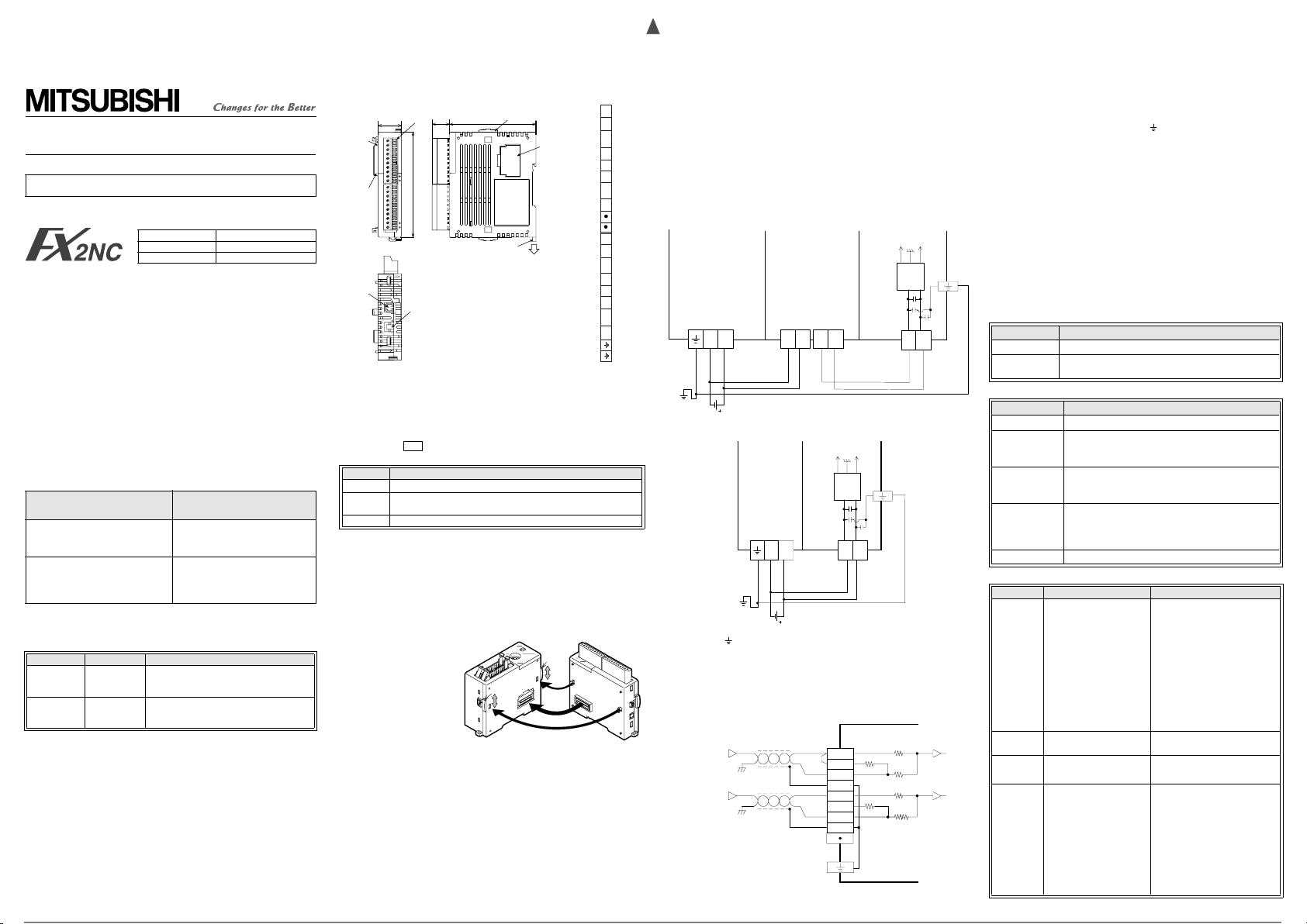
2. External Dimensions and Part Name
Terminal
arrangement
4)
3)’
5)
2NC
-4AD.
V1+
I1+
COM1
SLD
V2+
I2+
COM2
SLD
V3+
I3+
COM3
SLD
V4+
I4+
COM4
SLD
V1+
I1+
COM1
SLD
V2+
I2+
COM2
SLD
V3+
I3+
COM3
SLD
V4+
I4+
COM4
SLD
(0.6")
2)
90(3.55")
15
74(2.92")
20.2
(0.8")
1)
PW
24V
A/D
3)
6)
7)
Dimensions: mm(inch)
Outer facing color: Munsell 0.08GY/7.54/0.81
Weight: Approx. 130g (0.29lbs)
(Includes terminal block)
Accessory: Special function block number lab el, Power crossover cable
1) Status indicator LED 2) Terminal connector (European type)
3),3)’Extension por t 4) Slide lock for extension block
5) DIN rail clip 6) Power supply connector (24V DC)
7) Power supply connector (Supp ly for extension block)
The connector 3)' is equi pped with a cover.
- Never wire the terminals.
• Status indicator LED
FX
2NC
-10BPCB1
•
Indication Description
PW Lit while 5 V power is normally supplied fro m PLC.
24 V
Lit while 24 V power is normally suppli ed to the "24+" and "24-"
power supply connector of the FX
A/D Flashes during A/D conversion.
2NC
• Instal l the FX
special function block of the FX
• DIN rail in stallation
The FX
When removing the FX
hook.
For further de tails, refer to the Handy Manual packed together wi th on the PLC
main unit.
-4AD on the right si de of the main unit, extension block or
2NC
-4AD can be installed on DIN rail DIN46 277 (width: 35mm (1.38")).
2NC
Series PLC.
2NC
-4AD, push downward on the DIN rail attachment
3. PLC Connection
When connec ting the F X
4AD to the FX
unit or extension block,
remove the extension port
cover from the right s ide of the
main unit or extension block,
keep the slide lock in th e main
unit or extension block pulled
upward, then align the hoo k in
2NC
the FX
mounting hole in the former
step of the main unit or
extension block.
Then push the slide lock downward to fix the FX
or more FX
unit in the same way.
Up to four special function blocks or special function units in total can be
connected to the FX
CNV-IF.
For each connected special funct ion block or special function unit, a unit numb er
is assigned star ting with 0 for the speci al function block and special fu nction unit
nearest to the main u nit.
From the main unit, use FROM/TO instructions to read or write data stored in
the FX
-4AD with the
2NC
2NC
-4AD.
2NC
2NC
Series main
-
Slide lock
Main unit
2NC
-4AD. When connecting two
-4AD units, connect an FX
2NC
Series PLC including those connected to the FX
2NC
-4AD unit to another FX
Slide
lock
Hook
Hook
2NC
-4AD
FX
2NC
-4AD
2NC
4. Wiring
4.1 Power supply wiring
Supply power (24V DC) to the FX
When using the power supply connector, the following power cables are
available.
Power cables
2NC
-10BPCB 1:
FX
Power crossover cable (offered as an accessory for the FX
2NC
-100BPC B:
FX
Power cable (offered as an accessory for the FX
1) Connection example with the power supply throu gh crossover wiring to the
2NC
input extension block
FX
FX
main unit
2NC
Power supply
connector
24+24-
Red*2Green
Power crossover
cable FX
100BPCB
Grounding
resistance
100Ω or less
Connected to ground of the power supply
DC24V ±10%
2) Connection example to the external power supply
Grounding
resistance
• Con nect the " " terminal together w ith the ground terminal of the P LC main
unit to the ground of the power su pply equipped with groundi ng resistance of
100Ω or less.
• For crossover wir ing to the next block of the FX
cover from the power crossover connector.
100Ω or less
4.2 Input wiring
For terminal arrangement, r efer to Chapter 2 of this manual.
Current
input
Voltage
-
input
input extension block
Power
supply
connector
-
2NC
FX
2NC
main unit
Power supply
connector
24+24- 24+24-
Red*1Green Red*1
Power crossover
cable FX
DC24V ±10%
Input terminal block
Shield *1
2NC
-4AD from the power supply c onnector.
2NC
-4AD)
2NC
Series main unit)
FX
-4AD
FX
2NC
Power
supply
connector
24+24-
24+24-
Red*2
Power crossover
cable FX
FX
-4AD
2NC
AG
-15V
Power
circuit
Power
supply
connector
-
2NC
100BPCB
Connected to the ground of
2NC
V1+
*3
I1+
COM1
SLD
V2+
I2+
COM2
SLD
*4
2NC
AG
Power
circuit
Power
supply
connector
24+24-
-
2NC
10BPCB1
*1:Power terminal
*2:Black
+15V
Power
supply
terminal
*1:Black
power supply
-4AD, remove the resin
2NC
FX
-4AD
6.8kΩ
250Ω
200kΩ
*2
6.8kΩ
250Ω
200kΩ
+15V-15V
Red*2
CH1
CH2
*1 When wiring the anal og output cable, use a shielded two-core twisted
cable, and separat e it from other p ower cables and cables ea sily affected
by induction.
*2 The SLD terminal is connected to the
*3 For current input, short-circuit the VO+ terminal and the IO+ terminal (O:
Input channel No.).
*4 Do not wire the
Terminal connector handling
The FX
equivalent to that of the ter minal connector type FX
For the specifications of the suggested screwdriver, the dimensions of the
cable terminal, the external dimensions of the bar terminal equipped with
insulating sleeve, and applicable wiring, please refer to the FX
Manual.
""
terminal.
•
2NC
-4AD is equipped with a terminal connector whose form is
""
terminal inside t he FX
5. Specifications
5.1 General specifications
*1
The general specifications are equivalent to those of the PLC main unit.
(Please refer to the FX
5.2 Power supply specifications
Item Specifications
Analog circuits 24V DC±10%, 130 mA, externally supplied.
Digital circuits
5.3 Performance specifications
Item Sp ecifications
Conversion speed 1 ms x Numbe r of used channels
Isolated method
Number of
occupied I/O
points
Applicable PLC
Built-in memory E EPROM
5.4 Voltage/current input specifications
Item Voltage input Current input
Analog input
range
Digital output
Resolution
To t a l
accuracy
2NC
Handy Manual.)
5V DC, 50 mA, supplied from the PLC main unit us ing an
extension port.
Photocoupler isolated analo g input area from PLC.
Trans isolated power supply from analog I/O.
Channels are not isolated from each other.
8 points (including input and output points)
2NC
Series PLC
FX
(Up to four units can be connected including s pecial
function blocks and special function units connected to
2NC
-CNV-IF.)
FX
-10 to 10V DC
(input resistance: 200 kΩ)
Adjustment is enabled w ith
the following conditions:
Offset value: -10 to 9 V
Gain value: 10 V or less
"Gain - Offset": > 1 V
(except when
set in BFM #0 that disables
all changes to the offset or
gain.)
Maximum absolute input:
±15 V
Effective numeric value (15
bits) + Sign (1 bit)
0.32 mV (20 V × 1/64,000)
2.50mV (20 V × 1 /8,000)
Ambient temperature:
25 °C ± 5 °C
±0.3% (±60 mV) against
full scale 20 V
Ambient temperature:
0 to +55 °C
±0.5% (±100 mV) agains t
full scale 20 V
=2, 5, 8 is
!
-20 to 20 mA DC, 4 to 20 mA DC
(input resistance: 250 Ω)
Adjustment is enabled with the
following conditions:
Offset value: -20 to 17 mA
Gain value: 30 mA or less
"Gain - Offset": > 3 mA
(except when
BFM #0 that disables all changes
to the offset or gain.)
Maximum absolute input: ±30 mA
Effective numeric value (14 bits) +
Sign (1 bit)
µ
A (40 mA × 1 /32,000)
1.25
µ
5.00
A (40 mA × 1/8,000)
Ambient temperature: 25°C ± 5°C
±0.5% (±200
scale 40 mA
4 to 20mA input is same (±200
µ
A)
Ambient temperature: 0 to +55°C
±1% (±400
40 mA
4 to 20mA input is same (±400
µ
A)
2NC
PLC.
=2, 5, 8 is set in
!
µ
A) against full
µ
A) against full scale
2NC
2NC
Handy
-4AD.
Page 2
FX -4AD
2NC
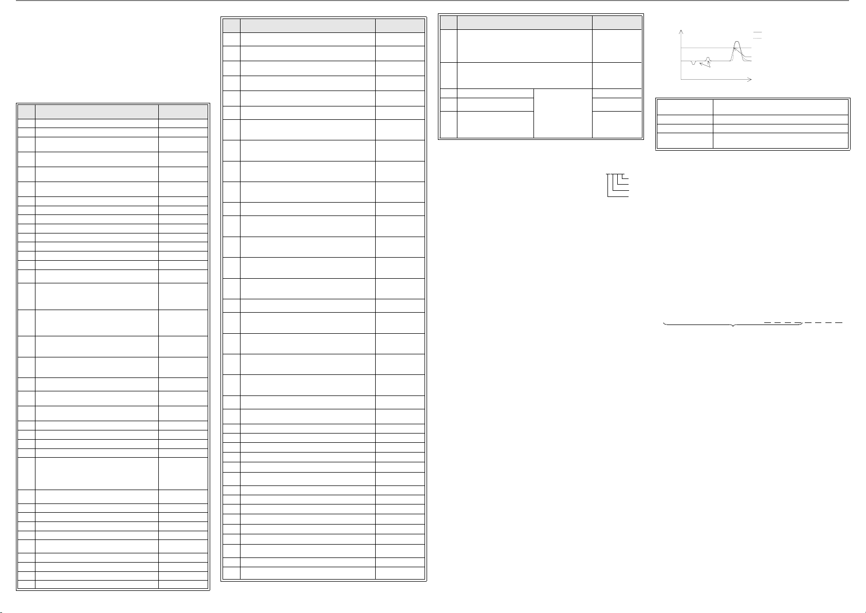
6. Buffer Memory (BFM)
Analog
value
Digital filter set value
Analog input value
They are converted into stable digital output values.
The digital output value follows up the
analog input value.
Time
Digital output value
BFM21
b15, b14, b13, b12 , b11, b10, b9, b8, b7, b6, b5, b4, b3, b2, b1, b0
CH4
CH3
CH2 CH 1
Invalid
Data transfer between the FX
via buffer memories (hereafter referred to as "BFM") of the FX
Each BFM consists of 1 word, 16 bits. BFM No. 0 to 1799 have assigned
functionality, communication with these BFMs should be performed using
TO/FROM instructions supplied by the PLC main unit.
When the power is switched ON from OFF, the initia l value is written to each
BFM. Create a program for the PLC so that the desired contents are wr itten
to the BFMs every time the power of the PLC is turned ON.
(The contents stored in BFM #0, #19, #22, #41 to #44 and #51 to #54 are
held in the built-in EEPROM, and kept against power failure.)
6.1 Buffer Memories (BFM) lists
BFM
No.
#0 Specifies input mode of CH1 to CH 4. H0000
#1 Reserved
Number of averaging times for CH1
#2
Setting range: 1 to 4,095 times
Number of averaging times for CH2
#3
Setting range: 1 to 4,095 times
Number of averaging times for CH3
#4
Setting range: 1 to 4,095 times
Number of averaging times for CH4
#5
Setting range: 1 to 4,095 times
#6 CH1: Digital filter setting Set range: 0 to 1,600 K0
#7 CH2: Digital filter setting Set range: 0 to 1,600 K0
#8 CH3: Digital filter setting Set range: 0 to 1,600 K0
#9 CH4: Digital filter setting Set range: 0 to 1,600 K0
#10 CH1 data (immediat e data or average data)
#11 CH2 data (immediat e data or average data)
#12 CH3 data (immediat e data or average data)
#13 CH4 data (immediat e data or average data)
•
••Reserved
Disables setting change of I/O characte ristics
(BFM #0, BFM #1, BFM #21) and co nvenient
#19
functions (BFM #22).
Disables change: K2, Enables change: K1
Initializes functions.
(Initializes functions at K1, then retur ns
#20
automatically to K0 after initializa tion is
completed.)
Writes I/O charac teristics. (Returns
#21
automatically to K0 after write of offset/gain
value is finished.)
Sets convenient functions (data addition , upper/
#22
lower limit value detection, sudden change
detection and minimum/max imum value hold).
•
••Reserved
Upper/lower limit value error status (valid while
#26
BFM #22 b1 is ON)
A/D data sudden change detec tion status (valid
#27
while BFM #22 b2 is ON)
#28 Scale over status K0
#29 Error status K0
#30 Model code (K2070) K2070
#31 Reserved
Operating time 0 to 64,800 (s)
Subsequently, 64,800 is kept.
Measurement star ts when the power is turned
#32
on, and the measured value is reset when the
power is turned off.
•
••Reserved
#41 CH1 offset data (mV or µA) K0
#42 CH2 offset data (mV or µA) K0
#43 CH3 offset data (mV or µA) K0
#44 CH4 offset data (mV or µA) K0
•
••Reserved
#51 CH1 gain data (mV or µA) K5000
#52 CH2 gain data (mV or µA) K5000
#53 CH3 gain data (mV or µA) K5000
#54 CH4 gain data (mV or µA) K5000
2NC
-4AD and the PLC main unit is performed
Description Initial value
2NC
K1
K1
K1
K1
K1
K0
K0
K0
K0
K0
K0
-4AD.
BFM
No.
•
••Reserved
CH1 addition data Setting range: -16,00 0 to 16,000
#61
(valid while BFM #22 b0 is ON)
CH2 addition data Setting range: -16,00 0 to 16,000
#62
(valid while BFM #22 b0 is ON)
CH3 addition data Setting range: -16,00 0 to 16,000
#63
(valid while BFM #22 b0 is ON)
CH4 addition data Setting range: -16,00 0 to 16,000
#64
(valid while BFM #22 b0 is ON)
•
••Reserved
CH1 lower limit error set value (valid while BFM #22
#71
b1 is ON)
CH2 lower limit error set value (valid while BFM #22
#72
b1 is ON)
CH3 lower limit error set value (valid while BFM #22
#73
b1 is ON)
CH4 lower limit error set value (valid while BFM #22
#74
b1 is ON)
•
••Reserved
CH1 upper limit error set value (valid while BFM #22
#81
b1 is ON)
CH2 upper limit error set value (valid while BFM #22
#82
b1 is ON)
CH3 upper limit error set value (valid while BFM #22
#83
b1 is ON)
CH4 upper limit error set value (valid while BFM #22
#84
b1 is ON)
•
••Reserved
CH1 sudden change detection set value
#91
Setting range: 1 to 50% of full scale (valid while BFM
#22 b2 is ON)
CH2 sudden change detection set value
#92
Setting range: 1 to 50% of full scale (valid while BFM
#22 b2 is ON)
CH3 sudden change detection set value
#93
Setting range: 1 to 50% of full scale (valid while BFM
#22 b2 is ON)
CH4 sudden change detection set value
#94
Setting range: 1 to 50% of full scale (valid while BFM
#22 b2 is ON)
•
••Reserved
Clear of upper and lower limit value error an d sudden
#99
change detection erro r
#100 Reserved
#101 CH1 minimum value (valid while BFM #22 b3 is ON)
#102 CH2 minimum value (valid while BFM #22 b3 is ON)
#103 CH3 minimum value (valid while BFM #22 b3 is ON)
#104 CH4 minimum value (valid while BFM #22 b3 is ON)
•
••Reserved
#109 Minimum value reset K0
#110 Reserved
#111 CH1 maximum value (valid while BFM #22 b3 is ON)
#112 CH2 maximum value (valid while BFM #22 b3 is ON)
#113 CH3 maximum value (valid while BFM #22 b3 is ON)
#114 CH4 maximum value (valid while BFM #22 b3 is ON)
•
••Reserved
#119 Maximum value reset K0
•
••Reserved
Description Initial value
Minimum digital
value inside input
range
Minimum digital
value inside input
range
Minimum digital
value inside input
range
Minimum digital
value inside input
range
Maximum digi tal
value inside input
range
Maximum digi tal
value inside input
range
Maximum digi tal
value inside input
range
Maximum digi tal
value inside input
range
5% of full scale
5% of full scale
5% of full scale
5% of full scale
BFM
No.
Data history sampling time
[Effective only for channels whose number of
#198
averaging times (BFM #2 to #5) is 1 and digital filter
K0
K0
K0
K0
setting (B FM #6 to #9) is 0]
Setting range: 0 to 30,000 ms
Resets or stops data history.
[Effective only for channels whose number of
#199
averaging times (BFM #2 to #5) is 1 and digital filter
setting (B FM #6 to #9) is 0]
#200 CH1 data history (1st value) Data history sampling
•
•
•
CH4 data history (400th
#1799
value)
Description Initial value
•
•
•
is effective only for
channels whose
number of averaging
times (BFM #2 to #5)
is 1 and digital filter
setting (BFM #6 to #9)
is 0.
K0
K0
K0
•
•
•
K0
6.2 Details of buffer memories
BFM #0: Specifies input mode.
Specify the input mod e of CH1 to CH4 by writing a numeri c
value to BFM #0.
The input mode specifi cation declares, each BFM expressed
as a 4-digit hexadecimal code, and each channel No. is
assigned to each digit. S pecify a numer ic value 0 to F in
each digit for each channel.
=0: Voltage input mode (-10 to 10V → -32000 to 32000),
!
resolution 0.32mV
=1: Voltage input mode (-10 to 10V → -4000 to 4000), resoluti on 2.50mV
!
=2: Voltage input mode (-10 to 10V → -10000 to 10000), resolution 1mV
!
=3: Current input mode (4 to 20m A → 0 to 16000), resolutio n 1.25 µA
!
=4: Current input mode (4 to 20 m A → 0 to 4000), resolution 5.00 µA
!
=5: Current input mode (4mA to 20mA → 4000 to 20000), resolut ion 1.25 µA
!
=6: Current input mode (-20 to 20 mA → -16000 to 16000), resolutio n 1.25 µA
!
=7: Current input mode (-20 to 20 m A → -4000 to 4000), resoluti on 5.00 µA
!
=8: Current input mode (-20 to 20 m A → -20000 to 20000), resolutio n 1.25 µA
!
=9 to E:Unusable
!
=F: Corresponding CH is not used.
!
• The input characteristics are changed autom atically according to the setting of
BFM #0. (The input characteristics can be ch anged to independent values
except when !=2, 5, 8 is set in BFM #0 that disables all changes to the of fset or
)
gain.
• It ta kes approximately 5 seconds to chang e the input mode (to ch ange each
set value).
Time interval of 5 seconds or more after changi ng the input mode until the
write of each setting (TO instr uction) is performed.
•
Setting "HFFFF" to allocate all channels as unusable is not allowed.
BFM #2 to BFM #5: Num ber of averaging times
(Make sure to set the number of averaging times to "1" when using the digital
filer.)
The allowable set range of the number of averaging times is 1 to 4,095.
If the number of averaging times is set to "1", the immediate data (curren t value)
is stored in BFM #10 t o #13. Otherwise, BFM #10 to BFM #13 will be averaged
depending on the value set i n BFM #2 to BFM #5.
If the number of averaging times is set to "0" or less, "0" is wr itten. If the number
of averaging times is set to "4,096" or more, "4096" is written. In either case,
number of averaging times setting error (BFM #29 b10) occurs. The initial set
K0
value is "1 ".
Average data update
• When the number of averaging times (BFM #2 to BFM #5) is set to "400 " or
less, the average (BFM #10 to BFM #13 ) is updated every time the A/D
conversion processing is performed.
The update time is as follows:
Average data update time = (A/D conversion time) x Number of channels
• When the number of averaging times (BFM #2 to BFM #5) is set to "401 " or
more, the average (BFM #10 to BFM #13) is updated every time the A/D
conversion is performed by as many as the s et number of averaging times.
The update time is as follows:
Average data update time = (A/D conversion time) x Number of channels x
Number of averaging times
In either case above, until the numbe r of A/D conversion times reaches the set
number of averaging times for the first time, the average at each time point is
stored in BFM #10 to BFM #13.
BFM #6 to BFM #9: Digit al filter setting
(Effective only when the number of averaging times i s set to "1")
Setting BFM #6 to BFM #9 to "1" invokes, the digital filter whic h can be provided
for each channel. If the fluctuation of the analog input value is less tha n the set
value of BFM #6 to #9, the analog input value is conver ted into a stabilized
digital outp ut value. If the analo g input value exceeds th e set value, the
proceeding digital conversion value will follow and replicate there values. The
data is updated every "5ms x Number of channel s", and stabilized by the last 20
data.
BFM#0
!!!!
H
By this function, un stable analog values can be co nverted into stable digital
values.
The table below shows the relationship between the s et value of BFM #6 to
#9 and the operation.
Set value < 0
Set value = 0 Digital filter functi on is invalid.
1 ≤ Set value ≤ 1,600 Digital filter function is valid.
1,600 < Set value
BFM #10 to BFM #13: Cha nnel data
The A/D conversion data for each channel is written to BFM #10 to #13.
BFM #19: Disables setting change
BFM #19 enables or disables the setting change of the I/O characteristics
CH1
(BFM #0, #41 to #44, #5 1 to #54), the convenient function s (BFM #22).
CH2
CH3
CH4
K1: Enables change (factor y default).
K2: Disables change.
BFM #20: Initializes functions
BFM #20 initializes all data stored in BFM #0 to BFM #1799, and sets the
2NC
-4AD to factory default.
FX
By initialization, the input characteristics are reset to the values set at
factory default (voltage input, off set value K0, gain value K5000).
K0: Normal
K1: Executes initialization. (Wr ites K1, subsequently returns to K0
when initialization is completed.)
BFM #21: Writes I/O cha racteristics
Each channel No. is assigned to th e lower 4 bits of BFM #21.
When a bit is set to ON, the o ffset data (BFM #41 to BFM #44 ) and the gain
data (BFM #51 to BFM #54) of the assigned channel No. are written to the
built-in memory (EEPROM).
Give the write command to two or more channels at a time. (When enteri ng
"HF", all channels are wr itten to.)
When the write is c ompleted, BFM #21 subs equently returns to K 0.
BFM #22: Sets convenient functions
The functions des cribed below are as signed to b0 to b 3 of BFM #22. Wh en
a bit is set to ON, the a ssigned function becom es valid.
When a bit is set to O FF, the ass igned function becomes invalid.
b0: Data addition function
The data (BFM #10 to BFM # 13), minimum/maximum value (BFM #1 01
to BFM #104, BFM #111 to BFM #114) and data history (BFM #200 to
BFM #1799) of each channel is the measured value added by the
addition data (BFM #6 1 to BFM #64).
When using this function, enter the value added by the addition data
(BFM #61 to BFM #64) to the lower limit value error set value (BFM
#71 to BFM #74) and the upper l imit value error set value (BFM #81 to
BFM #84).
The addition data (BFM #61 to BFM #64) is not added to the scale over
data (BFM #28).
b1: Upper/lower limit value detection fu nction
When the A/D conversion data of each channel is outside the range of
the lower limit value error set value (BFM #71 to BFM #7 4) to the upper
limit value error set value (BFM #81 to B FM #84), the result is wri tten to
the upper/lower limit value error s tatus (BFM #26).
b2: Sudden change detec tion function
When the data (BFM #10 to BFM #13) of each channel is updated, if
the difference between the previous value and the new value is larger
than the sudden change detection set value (BFM #91 to BFM #94),
the result is written to the sudden change dete ction status (BFM #27).
b3: Minimum/maximum value hold func tion
The minimum value of the data (BFM #10 to BFM #13) o f each channel
is written to BFM #101 to BFM #1 04, and the maximum value is written
to BFM #111 to BFM #11 4.
BFM #26: Upper/lower limit error status
The upper /lower limit value detection function (BFM#22 b1), writes
detected errors to the corresponding bits in BFM#26 (see table). Upper and
lower limit error status for the four channels is located i n bit-pairs in the first
8bits of BFM#26.
When the data (BFM #10 t o BFM #13) of any channel is outside the range
from the lower limit error value (BFM #71 to BFM #74) to the upper limit
error value (BFM #81 to BF M #84), the correspondi ng bit turns ON.
When a bit turns ON, it remains ON until it is reset by BFM #99 or the
power is turned OFF.
Digital filter function is invalid. Set value error occ urs
(BFM #29 b11 turns ON .).
Digital filter function is invalid. Set value error occ urs
(BFM #29 b11 turns ON .).
Page 3

Even while an upper/lower limit value e rror is detected, the data (BFM #10
to BFM #13) of each cha nnel continues to be updated .
Bit assignment of
Bit No. Channel No. Description
b0
b1 Upper limit error
b2
b3 Upper limit error
b4
b5 Upper limit error
b6
b7 Upper limit error
BFM #27: A/D data sudden change detection status
The sudden change detec tion function (BFM#22 b2) writes detected errors
to the corresponding b its in BFM#27. The sud den change detection stat us
for negative or positive changes is located in the first 8bits of BFM#27 in
bit-pairs.
When the data (BFM #10 to BFM #13) of each channel is updated, if the
difference between the previous value and the new value is larger than the
sudden change detection set value (BFM #91 to BFM #94), the
corresponding bit in BF M #27 turns ON.
At this time, when t he new value is larger tha n the previous value, a bit for
the + direction tur ns ON. when the new value is smalle r than the previous
value, a bit for the - direction turns ON.
When a bit turns ON, it remains ON until it is reset by BFM #99 or the
power is turned OFF.
Even while a sudden change error is detected , the data (BFM #10 to BFM
#13) of each channel co ntinues to be updated.
Bit assignment of
Bit No. Channel No. Description
b0
b1 Sudden change error in + direction
b2
b3 Sudden change error in + direction
b4
b5 Sudden change error in + direction
b6
b7 Sudden change error in + direction
BFM #28: Scale over status
The result of the analog input value for each individual channel that has
exceeded the A/D conversion range will be wr itten to BFM#28.
Range in which A/D conversion is available:
- 10.2V to 10.2V - 20.4mA to 20.4mA
A bit will remain ON unless it is reset from switching the Power OFF or
overwriting the ON bit with an OFF bit via a TO instruction.
Even while a scale over error is detected, the data (BFM #10 to BFM #13 )
of each channel continues to be updated.
Bit assignment of
Bit No. Channel No. Description
b0
b1 Scale over: More t han upper limit
b2
b3 Scale over: More t han upper limit
b4
b5 Scale over: More t han upper limit
b6
b7 Scale over: More t han upper limit
BFM #29: Error status
Error information is ass igned to each bit of BF M #29.
Bit assignment of
Bit
No.
b0 Error detected b0 is O N while either b2 to b4 is ON.
b1
BFM #26
CH1
CH2
CH3
CH4
Lower limit error
Lower limit error
Lower limit error
Lower limit error
BFM #27
CH1
CH2
CH3
CH4
Voltage input mode Current input mode
Sudden change error in - direction
Sudden change error in - direction
Sudden change error in - direction
Sudden change error in - direction
BFM #28
CH1
CH2
CH3
CH4
Scale over: Less than lower limit
Scale over: Less than lower limit
Scale over: Less than lower limit
Scale over: Less than lower limit
BFM #29
Assignment Description
Bit
Assignment Description
No.
b2 Power error
b3 Hardware error
A/D conversion value
b4
error
b5
b6 BFM read/write disabled
b7
b8 Set value error detected This bit will be ON while either b9 to b15 is ON.
b9 Input mode setting error
b10
b11 Digital filter setting error
b12
b13
b14
b15 Addition da ta setting error
BFM #30: Model code
BFM #30 stores a fixed value of "K 2070".
BFM #32: Operating time
BFM #32 stores the cont inuous operating time for the FX
Measurement starts when the power is turned ON, and the measured value is
reset when the power is tur ned OFF.
The measurement range is from 0 to 64,800 (s). After that, 64,800 is kept.
BFM #41 to BFM #44: Of fset data
BFM #51 to BFM #54: Gain d ata
Offset data :Analog input value when the d igital value is "0"
Gain data :Analog input value when the digi tal value is as shown below (The
Standard digital value for offset and gain in each input mod e
(A number in the input m ode column indicates a value set in BFM #0.)
Input mode (BFM #0) 012345678
Standard offset value 00-00-00-
Standard gain value 16000 20 00 - 1 6000 4000 - 16000 40 00 -
• Set the offset and gain data for each channel.
• Wr ite the set value in units of "mV" for voltage input or "µA" for current input.
• Do n ot change the input characteristics when
(Even if a numerical value is wr itten, it is ignored.)
Initial offset/gain value (Uni t: mV for voltage input, µA for current input)
Input mode (BFM #0) 012345678
Initial offset value 0 4000 0
Initial gain value 5000 20000
Number of averaging
times setting error
Sudden change dete ction
set value error
Upper/lower limit set value
error
digital value varies depending on the setting of the input mode.)
24V DC power is not correctly supplied.
Check the wiring and supply voltage.
2NC
-4AD may have malfunctioned.
FX
Contact the nearest Mitsubishi Electric System
Service center.
A/D conversion value is abnormal.
Using the scale over data (BFM # 28), check the
channel in which the error has occurred.
This bit will be ON during the input
characteristics change pr ocessing. While this bit
is ON, correct A/D data will not read from or
written to BFMs.
Input mode (BFM #0) is incorrectly s et.
Set it within the range from 0 to 8.
Number of averaging times is incorrectly set.
Set it within the range from 1 to 4,095.
The digital filter setting is incorrect.
Reset within the rang e of 0 to 1,600 .
Sudden change detection set value is incorrect.
Set a correc t value.
Upper/lower limit set value is incorrect. Set a
correct value.
Addition data is incorrectly set.
Set it within range from -16,000 to 16,00 0.
2NC
-4AD.
2, 5, 8 is set in BFM #0.
=
!
Setting range
Offset data -1000 to 9000 (mV) -20000 to 17000 (µA)
Gain data
Voltage input Current input
Gain value - Offset value
= 1,000 to 10,000 (mV)
Gain value - Offset value
= 3,000 to 30,000 (µA)
The actual effective input range is "-10 t o 10 V" or "-20 to 20 m A".
BFM #61 to BFM #64: Additi on data
When using the data addition function (BFM #22 b0), data (BFM #10 to BFM
#13), minimum/maximum value (BFM #101 to BFM #104, BFM #111 to BFM
#114) and data histor y (BFM #200 to BFM #1799) of each channel becomes the
measured value added by the ad dition data (BFM #61 to BFM #64).
When using the data addition function, enter the value added by the addition
data (BFM #61 to BFM #64) to the lower limit value error set value (BFM #71 to
BFM #74) and the up per limit value error set value (BFM #8 1 to BFM #84).
Setting range: -16,000 to 1 6,000
BFM #71 to BFM #74: Lower limit, error set value
BFM #81 to BFM #88: Upp er limit, error set value
When using the upper/lower limit value detection function (BFM #22 b1), write
the lower limit value of each chan nel to BFM #71 to BFM #74 and the upper limit
value of each channel to BFM #81 to BFM #84.
When using the data addi tion function (BFM #22 b0), ent er the value added by
the addition data to BFM #61 to BFM #64.
Setting range
The setting range will vary depending on the setting of the input mode (BFM #0).
The table below shows th e setting range for each input mode. Enter th e set
value as a digital value.
Input mode (BFM #0) Setting range
0: Voltage input mode
(-10 to 10 V → -32000 to 32000)
1: Voltage input mode
(-10 to 10 V → -4000 to 4000)
2: Voltage input mode
(-10 to 10 V → -10000 to 10000)
3: Current input mode
(4 to 20 mA → 0 to 16000)
4: Current input mode
(4 to 20 mA → 0 to 4000)
5: Current input mode
(4 to 20 mA → 4000 to 20000)
6: Current input mode
(-20 to 20 mA → -16000 to 16000)
7: Current input mode
(-20 to 20 mA → -4000 to 4000)
8: Current input mode
(-20 to 20 mA → -20000 to 20000)
BFM #91 to BFM #94: S udden change detection set valu e
When using the sudden chan ge detection function (BFM #22 b2), enter the set
value to judge the sudden ch ange.
When the data (BFM #1 0 to BFM #13) of eac h channel is updated, i f the
difference between the previous value and the new value is larger than the
sudden change detec tion set value (BFM #91 to BFM #94), the result i s written
to the sudden change d etection status (BFM #27 ).
Setting range
The setting range will vary depending on the setting of the input mode (BFM #0).
The table below shows the setting r ange for each input mode.
Write the set value in a digital value.
BFM #99: Clears upper/lower limit value error and sudden change
detection error
The commands to clear the lower and upper limit value error and the sudden
change detection err or are assigned to the lower thre e bits of BFM #99.
The flag of the corresponding error status (BFM #26, BFM #27) is reset for all
channels simultaneously when a bit is set to ON.
After the reset is finishe d, each bit of BFM #99 re turns automatically to the OFF
state.
The setting of two or more c lear commands to ON at the same time is possible.
Input mode (BFM #0) Setting range Initial va lue
0: Voltage input mode
(-10 to 10 V → -32000 to 32000)
1: Voltage input mode
(-10 to 10 V → -4000 to 4000)
2: Voltage input mode
(-10 to 10 V → -10000 to 10000)
3: Current input mode
(4 to 20 mA → 0 to 16000)
4: Current input mode
(4 to 20 mA → 0 to 4000)
5: Current input mode
(4 to 20 mA → 4000 to 20000)
6: Current input mode
(-20 to 20 mA → -16000 to 16000)
7: Current input mode
(-20 to 20 mA → -4000 to 4000)
8: Current input mode
(-20 to 20 mA → -20000 to 20000)
-32768 to 32767 -32768 32767
-4096 to 4095 -4096 4095
-10200 to 10200 -10200 10200
-1 to 16383 -1 16383
-1 to 4095 -1 4095
3999 to 20400 3999 20400
-16384 to 16383 -16384 16383
-4096 to 4095 -4096 4095
-20400 to 20400 -20400 20400
1 to 32767 3200
1 to 4095 400
1 to 10000 1000
1 to 8191 800
1 to 2047 200
1 to 8191 800
1 to 16383 1600
1 to 4095 400
1 to 20000 2000
Initial value
Lower
limit
Upper
limit
Bit assignment of BF M #99
Bit No. Descriptio n
b0 Clears lower limit error.
b1 Clears upper limit erro r.
b2 Clears sudden change detection error.
b3 to b15 Unusable
BFM #101 to BFM #104: Minimum value
BFM #111 to BFM #114: Maximum value
When using the minimum/m aximum value hold function (BFM #22 b3), the
minimum value of the data (BFM #10 to BFM #13) of each channel is
written to BFM #101 to BFM #104, and the maximum value is written to
BFM #111 to BFM #114 .
When using th e data addition function (BFM #22 b0), the min imum/
maximum measured value will be added to the addition data (BFM #61 to
BFM #64).
Initial value
Minimum/maximum value hold function is not used:K0
Minimum/maximum value hold fun ction is used: Digital value when the
BFM #109: Minimum value reset
BFM #119: Ma ximum value reset
When using the m inimum/maximum valu e hold function (B FM #22 b3),
BFM #109 clears the minimum value stor ed in BFM #101 to BFM #104,
and BFM #119 clears the ma ximum value stor ed in BFM #111 to BFM
#114.
The channel No. that will be r eset is assigned to eac h bit of BFM #109 and
BFM #119. When a bit is set ON, minimum/maximum value of the assigned
channel is cleared. (Setting two or more bits ON simultaneously is
possible.)
Bit assignment
BFM #109
BFM #119
BFM #198: Data histor y sampling time
Set the data histor y sampling time.
Setting range: 0 to 30,0 00 ms
Sampling cycle
When the set value is "0" :1 ms x Number of effective channels
When the set value is "1" or m ore:Set value (ms) x Number of effective
BFM #199: Resets or stops data history
The data history rese t function is assigned to the lower 4 bits of BFM #199.
The data history stop function is assigne d to the upper 4 bits of BFM #199.
Data history re set function
This function clears th e sampled data histor y for each channel.
The channel No. to be reset is assigne d to each of the lower 4 bits of BFM
#199.
When a bit is set to ON, the data history (all conte nts from the 1st value to
the 400th value) of the assigned channel is cleared. (The setting of two or
more bits to ON simultane ously is possible.)
When the clear operation is completed, each bit returns automatically to
the OFF state.
Assignment of lower 4 bits
Channel No. Unusable CH4 CH3 CH2 CH1
Data history sto p function
This function will temporarily stop the data history for the individual
channels. The channel No. to be temporarily stopped is assigned to each
of the upper 4 bits of BFM #199. Whe n a bit is set to ON, sampling of the
data history of the assigned channel is temporarily stopp ed. (Setting two or
more bits to ON at a time.)
When a bit is set to OFF, sampling of the data history of the assigned
channel restar ts.
Assignment of upper 4 bits
Channel No. Unusable CH4 CH3 CH2 CH1
Bit No. b15 to b4 b3 b2 b1 b0
Channel No.
(BFM No.)
Channel No.
(BFM No.)
Unusable
Bit No. b15 to b4 b3 b2 b1 b0
Unusable
channels
Bit No. b7 to b4 b3 b2 b1 b0
Bit No. b15 to b12 b11 b10 b9 b8
CH4
(#104)
CH4
(#114)
power is turned ON
CH3
CH2
(#103)
(#102)
CH3
CH2
(#113)
(#112)
CH1
(#101)
CH1
(#111)
Page 4

BFM #200 to BFM #1799: Data history
Refreshes t he watch
dog timer. *1
T0
K0 K200 D10 K10
K0 K600 D20 K10
K0 K1000 D30 K10
Reads the CH1 data
history (f or 10 times) to
D10 to D19.
Reads the CH2 data
history (f or 10 times) to
D20 to D29.
Refreshes t he watch
dog timer. *1
Reads the CH3 data
history (f or 10 times) to
D30 to D39.
FNC 78
FROM
FNC 07
WDT
FNC 78
FROM
FNC 07
WDT
FNC 78
FROM
FNC 07
WDT
K0 K1400 D40 K10
FNC 78
FROM
FNC 07
WDT
Reads the CH4 data
history (f or 10 times) to
D40 to D49.
END
Refreshes t he watch
dog timer. *1
Refreshes t he watch
dog timer. *1
The input mode setting will be kept by the EEPROM, therefore,
continual c hannel setti ngs is not needed af ter powering down.
1)
The A/D conversion value of each channel is sampled, and written to the
BFMs shown below. The table below shows the assignment between the
channel No. and the BFM No. Data is stored in ascending order of the BFM
No.
Up to 400 data history items are written for each channel. When the
number of history items exceeds 400, the data is overwritten s tarting from
the smallest BFM No.
The data history function i s valid only for channels whose number of
averaging times (BFM # 2 to #5) is set to "1 " and digital fi lter setting (BF M
#6 to #9) is set to "0".
Assignment of channel N o. and BFM No.
Channel
No.
1st value 2nd value 3rd value • • • • • 400th value
BFM No.
CH1 #200 #201 #2 02 • • • • • #599
CH2 #600 #601 #6 02 • • • • • #999
CH3 #1000 #1001 #1002 • • • • • #13 99
CH4 #1400 #1401 #1402 • • • • • #17 99
• If a cons iderable amount of data histo ry is read from the PLC main unit
using a FROM instruction , a watch dog timer error occu rs in the PLC
main unit.
In such a case, divide the r equired data histor y using multiple FROM
instructions, and inse rt the WDT instr uction (watch dog timer refr esh
instruction) after each FROM instruction.
7. Adjustment of I/O Characteristics
For factor y default, the FX
accordance with each inp ut mode (BFM #0).
In the voltage and current input mode, adjust the standard I/O
characteristics for each channel. (Do not change the input characteristics
when 2, 5, 8 is set in BEM #0.)
7.1 Standard I/O characteristics
The input mode of the standard I/O character istics is abbreviated as shown
below:
0. Voltage input, -10 to 10V, -32,000 to 32000
➁
➀
: Input mode set in BFM #0
➀
: Analog i nput rang e
➂
0. Voltage input, -10 to 10 V,
-32,000 to 32000
Digital value
Approx. 32640
32000
Input
voltage
-10
(V)
-10.2 V
Approx.
2. Voltage input, -10 to 10V,
-10,000 to 10,000
Digital value
Approx. 10,200
Input
voltage
(V)
-10.2 V
Approx.
10,000
-10
2NC
-4AD has standard I/O characteristics in
➂
-32000
Approx. -32640
-10,000
Approx.
-10,200
➃
10.2 V
Approx.
10
10.2 V
Approx.
10
: Input mode
➁
: Digital output range
➃
1. Voltage input, -10 to 10 V,
-4000 to 4000
Digital valu e
Approx. 4,080
4,000
Input
voltage
-10
(V)
-10.2 V
Approx.
3. Current input, 4 to 20 mA,
0 to 16000
Digital valu e
16000
04 20
10
-4,000
Approx. -4,080
Input current
(mA)
4. Current input, 4 to 20 mA,
0 to 4000
Digital value
4,000
04 20
6. Current input, -20 to 20 mA,
-16000 to 16000
Input
current
(mA)
8. Current input, -20 to 20mA,
-20,000 to 20,000
Input
current
(mA)
Input current
Digital valu e
16000
-20
0
-16000
Digital value
20,000
-20
0
-20,000
(mA)
20
20
5. Current input, 4 to 20mA ,
4,000 to 20,000
Digital value
20,000
4,000
04 20
7. Current input, -20 to 20 mA,
-4000 to 4000
Digital value
4,000
Input
current
-20
(mA)
7.2 Adjustment of I/O characteristics
Adjust the I/O characteristics using the buffer memories in the FX
Firstly, enter the input mode to BFM #0, then enter the offset dat a to BFM #41 to
10.2 V
Approx.
BFM #44, subsequentl y enter the gain data to BFM #51 to BFM #54.
Update the offset data and the gain data for each channel using BFM #21.
Example program (Adjustment of CH1, CH2 and CH4)
X000
Operation
start
instruction
M0
T0
FNC 79
K0 K0 H1600 K1
P
TO
M0
SET
*1
TO
K50
FNC 79
K0 K41 K0 K2
P
TO
FNC 79
K0 K51 K1250 K2
P
TO
FNC 79
K0 K44 K0 K1
P
TO
FNC 79
K0 K54
P
TO
FNC 79
K0 K21 H000F K1
P
TO
K10000
RST M0
*1 It takes approximately 5 s econds to change the input m ode (BFM #0) (to
change each set value).
Assure that a time interval of 5 second s or more is held after a change of the
input mode until execution of wri te of each setting (TO instruction).
• The I /O characteristics can be written (BFM #21) to ei ther channel, or two or
more channels simultaneously.
Specifies the input
mode of CH1 to CH4.
Offset value of CH1
and CH2.
Gain value of CH1 and
CH2.
Offset value of CH4.
Gain value of CH4.
K1
Offset valu e and gain
value of all channels at
a time.
Input current
(mA)
0
-4,000
2NC
20
-4AD.
8. Example program
This section introduces an example program to read analog data from the
2NC
-4AD and connecting to d igital data in the PLC.
FX
Condition
System configuration:
2NC
The FX
-4AD is connected as a special function block nearest to the
2NC
Series PLC main unit (un it No. 0).
FX
Input mode:
CH1 and CH2: Mode 0 (voltage input , -10 to 10 V → -32000 to 32000)
CH3 and CH4: Mode 3 (current i nput, 4 to 20 mA → 0 to 16000)
Number of averaging times:
I/O characteristics:
Standard I/O character istics (initial value) in each c hannel
Convenient function:
Data history function:
Used while sampling time is set to 0ms (initial value) .
CH1 to CH4: Sampling time = 1ms × 4 (Number of effective channels) = 4ms
I/O assignment:
X001 : Clears the upper/lower limit value error.
X002 : Clears the scale over error.
Y000 to Y017: Output the up per/lower limit value error status of ea ch
Y020 to Y037: Output s cale over status of each channe l.
Example program
Initial pulse
M8002
RUN monitor
M8000
T0
Clear of
upper/lower
limit value
error
X001
Clear of scale over error
X002
Lower limit value error of CH1
M0
Upper limit value error of CH1
M1
Upper limit value error of CH4
M7
Scale over error of CH1 (lower limit value)
M20
Scale over error of CH1 (upper limit value)
M21
Scale over error of CH8 (upper limit value)
M27
channel.
FNC 79
TO
TO
FNC 79
TO
FNC 78
FROM
FNC 78
FROM
FNC 78
FROM
FNC 78
FROM
FNC 79
TO
FNC 79
TO
• • •
• • •
1 (initial value) in each chann el
Upper/lower limit value detection fun ction is used.
K0 K0 H3300 K1
K50
K0 K22 H0002 K1
P
K0 K10 D0 K4
K0 K26 K4M0 K1
K0 K28 K4M20 K1
K0 K29 D6 K1
K0 K99 H0003 K1
P
K0 K28 K0 K1
P
Specifies the input
mode of CH1 to
CH4.
Stand by for fi ve
seconds.
Enables the upper /
lower limit value
detection f unction.
Reads the ch annel data
from CH1 to CH4.
(CH1 → D0, CH2
D1,
Reads the upper/ lower
limit value error status.
(M0 to M15)
Reads the scale over
status.( M20 to M35)
Reads the error status.
(BFM #29 → D6)
Clears the upper/lower
limit value error.
Clears the scale over
error.
Y0
Outputs the upper /
Y1
lower limit value error
status of each
channel.
Y7
Y20
Y21
Outputs the scale over
error status of each
channel.
Y27
.....
CH4 → D3)
1)
→
*1 When multiple d ata history items are read, the scan tim e of the PLC
becomes longer.
2NC
In the FX
error indicator lamp lights and the PLC stops.
When reading many da ta history items, div ide data history items to be
read using two or more FROM instructions, then insert the WDT (watch
dog timer refresh) instruc tion between FROM instructions.
HEAD OFFICE : MITSUBISHI DENKI BLDG MARUNOUTI TOKYO 100-8310
HIMEJI WORKS : 840, CHIYODA CHO, HIMEJI, JAPAN
When exported from Japan, this manual does not require application to the Ministry of Economy,
Trade and Industry for service transaction permission.
Series PLC, when the scan time exceeds 200 ms, the CPU
Specifications are subject to change without notice
 Loading...