

Mitsubishi Electric FR-XC-18.5K-PWM, FR-XC-11K, FR-XC-7.5K, FR-XC-22K, FR-XC-15K Instruction Manual
...
INVERTER
XC
INSTRUCTION MANUAL
Multifunction regeneration converter
FR-XC-7.5K to 55K
FR-XC-18.5K-PWM to 55K-PWM
FR-XC-H7.5K to H55K
FR-XC-H18.5K-PWM to H55K-PWM
OUTLINE
INSTALLATION AND WIRING
PARAMETERS
PROTECTIVE FUNCTIONS
PRECAUTIONS FOR
MAINTENANCE AND
INSPECTION
SPECIFICATIONS
1
2
3
4
5
6
Thank you for choosing this Mitsubishi Electric multifunction regeneration converter.
WARNING
CAUTION
CAUTION
∗1 10 to +40°C (non-freezing) at the +40°C rating.
This Instruction Manual provides handling information and precautions for use of the this product. Incorrect handling might cause
an unexpected fault. Before using this product, always read this Instruction Manual carefully to ensure proper use of this product.
Please forward this Instruction Manual to the end user.
Fire prevention
Safety instructions
Do not attempt to install, operate, maintain or inspect the
product until you have read through this Instruction Manual
and supplementary documents carefully to use the equipment
correctly. Do not use this product until you have a full
knowledge of the equipment, safety information and
instructions.
Installation, operation, maintenance and inspection must be
performed by qualified personnel. Here, qualified personnel
means a person who meets all the following conditions.
• A person who possesses a certification in regard with
electric appliance handling, or person took a proper
engineering training. Such training may be available at your
local Mitsubishi Electric office. Contact your local sales office
for schedules and locations.
• A person who can access operating manuals for the
protective devices (for example, light curtain) connected to
the safety control system, or a person who has read these
manuals thoroughly and familiarized themselves with the
protective devices.
In this Instruction Manual, the safety instruction levels are
classified into "WARNING" and "CAUTION".
Incorrect handling may cause hazardous
conditions, resulting in death or severe
injury.
Incorrect handling may cause hazardous
conditions, resulting in medium or slight
injury, or may cause only material
damage.
Note that even the level may lead to a
serious consequence depending on conditions. Be sure to
follow the instructions of both levels as they are critical to
personnel safety.
Electric shock prevention
WARNING
Do not remove the front cover or the wiring cover while the power
of this product is ON. Do not operate this product with any cover
or wiring cover removed, as accidental contact with exposed
high-voltage terminals and internal components may occur,
resulting in an electrical shock.
Even if power is OFF, do not remove the front cover except for
wiring or periodic inspection as you may accidentally touch the
charged circuits and get an electric shock.
Before wiring or inspection, check that the LED display of the
operation panel is OFF. Any person who is involved in wiring or
inspection shall wait for 10 minutes or longer after power OFF,
and check that there are no residual voltage using a tester or the
like. The capacitor is charged with high voltage for some time
after power OFF, and it is dangerous.
This product must be earthed (grounded). Earthing (grounding)
must conform to the requirements of national and local safety
regulations and electrical code (NEC section 250, IEC 61140
class 1 and other applicable standards). A neutral-point earthed
(grounded) power supply must be used for 400 V class
multifunction regeneration converter to be compliant with EN
standard.
Any person who is involved in wiring or inspection of this product
shall be fully competent to do the work.
The product body must be installed before wiring. Otherwise,
electric shock or injury may result.
Do not subject the cables to scratches, excessive stress, heavy
loads or pinching. Doing so may cause an electric shock.
Do not change the cooling fan while power is ON as it is
dangerous.
CAUTION
This product must be installed on a nonflammable wall without
any through holes so that nobody touches the heatsink, etc. on
the rear side of the product. Installing it on or near flammable
material may cause a fire.
If this product has become faulty, the product power must be
switched OFF. A continuous flow of large current may cause a
fire.
Be sure to perform daily and periodic inspections as specified in
the Instruction Manual. If this product is used without any
inspection, a burst, breakage, or a fire may occur.
Injury prevention
CAUTION
The voltage applied to each terminal must be as specified in the
Instruction Manual. Otherwise a burst, damage, etc. may occur.
The cables must be connected to the correct terminals.
Otherwise a burst, damage, etc. may occur.
The polarity (+ and -) must be correct. Otherwise a burst,
damage, etc. may occur.
While power is ON or for some time after power-OFF, do not
touch the multifunction regeneration converter as it will be
extremely hot. Touching it may cause a burn.
Additional instructions
The following instructions must be also followed. If the product
is handled incorrectly, it may cause an unexpected fault, injury,
or electric shock.
CAUTION
Transportation and installation
This product must be transported in correct method that
corresponds to the weight. Failure to do so may lead to injuries.
Do not stand or place any heavy object on the product.
Do not stack the boxes containing products higher than the
number recommended.
When carrying this product, do not hold it by the front cover.
Doing so may cause a fall or failure of the product.
The installing orientation of the product must be correct.
Do not install or operate this product if it is damaged or has parts
missing.
Prevent conductive items such as screws and metal fragments, or
flammable substances such as oil from entering this product.
As this product is a precision instrument, do not drop or subject it
to impact.
The surrounding air temperature must be -10 to +50°C
freezing). Otherwise the product may be damaged.
The ambient humidity must be 95% RH or less (non-condensing).
Otherwise the product may be damaged. (For the details, refer to
page 29.)
The temporary storage temperature (applicable to a short limited
time such as a transportation time) must be between -20 and
+65°C. Otherwise the product may be damaged.
This product must be used indoors (without corrosive gas,
flammable gas, oil mist, dust and dirt etc.) Otherwise the product
may be damaged.
This product must be used at an altitude of 2500 m or less, with
If halogen-based materials (fluorine, chlorine, bromine, iodine,
2
5.9 m/s
or less vibration at 10 to 55 Hz (directions of X, Y, Z
axes). Otherwise the product may be damaged. (For the
installation at an altitude above 1000 m, consider a 3% reduction
in the rated current per 500 m increase in altitude.)
etc.), included in fumigants to sterilize or disinfect wooden
packages, infiltrate into this product, the product may be
damaged. Prevent residual fumigant components from being
infiltrated into the product when packaging, or use an alternative
sterilization or disinfection method (heat disinfection, etc.). Note
that sterilization of disinfection of wooden package should be
performed before packing the product.
∗1 (non-
CAUTION
Test operation
Before starting the operation, confirm or adjust the parameter
settings. Failure to do so may cause some machines to make
unexpected motions.
Before starting the operation, check the wiring of each peripheral
device. Faulty wiring may cause some machines to make
expected motions.
Safety instructions
1
WARNING
Usage
Any person must stay away from the equipment after using the
retry function as the equipment will restart suddenly after output
shutoff of this product.
Be sure to turn OFF the start (STF/STR) signal input to the
inverter before clearing the fault in the product as the inverter will
restart a motor suddenly after a fault clear.
Use only specified inverters. Connection of any other electrical
equipment to the output of this product may damage the
equipment.
Do not modify this product.
Do not remove any part which is not instructed to be removed in
the Instruction Manuals. Doing so may lead to a failure or
damage of this product.
CAUTION
Usage
Do not start or stop this product frequently with a magnetic
contactor on its input side. Doing so may shorten the life of this
product.
Use a noise filter or other means to minimize the electromagnetic
interference with other electronic equipment used nearby this
product and the inverter.
As all parameters return to their initial values after Parameter
clear or All parameter clear is performed, the needed parameters
for the product operation must be set again before the operation
is started.
Before running this product or the inverter which had been stored
for a long period, perform an inspection and a test operation.
To avoid damage due to static electricity, static electricity in your
body must be discharged before you touch this product.
A safety backup such as an emergency brake must be provided
for devices or equipment in a system to prevent hazardous
conditions in case of failure of this product, inverter, or an
external device controlling the inverter.
If the breaker installed on the input side of this product trips,
check for the wiring fault (such as short circuit) and damage to
internal parts of this product, etc. Identify and remove the cause
of the trip before resetting the tripped breaker and applying the
power to the product again.
When any protective function is activated, take an appropriate
corrective action before resetting the product to resume the
operation.
Maintenance, inspection and parts replacement
Do not carry out a megger (insulation resistance) test on the
control circuit of this product. Doing so will cause a failure.
Disposal
This product must be treated as industrial waste.
General instruction
For clarity purpose, illustrations in this Instruction Manual may be
drawn with covers or safety guards removed. Ensure all covers
and safety guards are properly installed in place prior to starting
operation.
2
Safety instructions

CONTENTS
1 OUTLINE 7
1.1 Pre-operation instructions 8
1.1.1 Features of FR-XC series converters ...............................................................................................................8
1.1.2 Function selection switch assembly (SW2) ....................................................................................................10
1.1.3 Product checking and parts identification .......................................................................................................10
1.1.4 Harmonic suppression guidelines in Japan ....................................................................................................11
1.2 Component names 14
1.3 FR-XC series converter and peripheral devices 16
1.4 Precautions for selecting peripheral devices 17
1.4.1 Techniques and measures for electromagnetic compatibility (EMC)..............................................................17
1.4.2 Peripheral device list.......................................................................................................................................19
1.4.3 Selecting the rated sensitivity current for the earth leakage circuit breaker ...................................................23
2 INSTALLATION AND WIRING 25
2.1 Removal and reinstallation of the converter covers 26
2.1.1 30K converters or lower ..................................................................................................................................26
2.1.2 37K converters or higher ................................................................................................................................27
2.2 Removal and reinstallation of the FR-XCB reactor cover 28
2.3 Installation of the converter and enclosure design 29
2.3.1 Converter installation environment .................................................................................................................29
2.3.2 Cooling system types for converter enclosure ................................................................................................31
2.3.3 Converter installation ......................................................................................................................................32
2.3.4 Protruding the heat sink through a panel........................................................................................................34
2.4 Installation of peripheral devices 36
2.4.1 Installation of reactor (FR-XCL) ......................................................................................................................36
2.4.2 Installation of box-type reactor (FR-XCB) .......................................................................................................37
2.5 Connection of the converter and the inverter 38
2.5.1 Inverter selection ..............................................................................38
2.5.2 Switching between the common bus regeneration mode and the power regeneration mode ........................40
2.5.3 Function enable/disable selection (Pr.416).....................................................................................................40
2.5.4 Inverter parameter settings.............................................................................................................................40
2.5.5 Temperature derating selection ......................................................................................................................40
2.6 Main circuit terminal specification 41
2.6.1 Details on the main circuit terminals ...............................................................................................................41
2.6.2 Main circuit terminal block layout....................................................................................................................41
2.6.3 Cable size of the main circuit terminals and the earth (ground) terminal........................................................43
2.7 Control circuit specification 50
2.7.1 Details on the control circuit terminals ............................................................................................................50
2.7.2 Control logic switchover..................................................................................................................................51
2.7.3 Control circuit terminal layout .........................................................................................................................53
2.7.4 Wiring precautions ..........................................................................................................................................55
2.7.5 Details on the control circuit terminals on the FR-XCB...................................................................................56
2.8 Wiring 57
CONTENTS
3

2.8.1 Terminal connection diagram ......................................................................................................................... 57
2.8.2 Wiring (common bus regeneration mode with harmonic suppression disabled) ............................................ 60
2.8.3 Wiring (power regeneration mode) ................................................................................................................. 62
2.8.4 Wiring (common bus regeneration mode with harmonic suppression enabled)............................................. 64
2.8.5 When using separate power supplies for the control circuit and the main circuit ........................................... 65
2.9 Earthing (Grounding) precautions 66
2.10 Connection of the converter and the multiple inverters 67
2.10.1 Connection in common bus regeneration mode............................................................................................. 67
2.11 PU installation on converter 70
2.12 Communication operation 71
2.13 Before powering and starting operation 72
2.13.1 Installation ...................................................................................................................................................... 72
2.13.2 Powering ........................................................................................................................................................ 72
2.13.3 Operation........................................................................................................................................................72
2.14 Digital characters and their corresponding printed equivalents 73
3 PARAMETERS 75
3.1 Operation panel (FR-DU08) 76
3.1.1 Components of the operation panel ............................................................................................................... 76
3.1.2 Basic operation of the operation panel (factory setting) .................................................................................77
3.1.3 Digital characters and their corresponding printed equivalents...................................................................... 78
3.1.4 Changing the parameter setting value ........................................................................................................... 78
3.2 Monitoring the converter status 79
3.2.1 Monitoring of input voltage or bus voltage...................................................................................................... 79
3.2.2 First priority monitor screen ............................................................................................................................79
3.3 Parameter unit (FR-PU07) / Parameter unit with battery pack (FR-PU07BB(-L)) 80
3.3.1 Components of the parameter unit ................................................................................................................. 80
3.3.2 Monitoring function ......................................................................................................................................... 81
3.3.3 Function menu................................................................................................................................................82
3.4 Parameter list 84
3.5 Parameter details 86
3.5.1 Showing/hiding extended parameters (Pr.0) .................................................................................................. 86
3.5.2 Power frequency input to the converter (Pr.1 and Pr.2) .................................................................................86
3.5.3 Input terminal function selection (Pr.3, Pr.4, and Pr.7)...................................................................................87
3.5.4 Operation selection for the SOF signal and the OH signal (Pr.8 and Pr.9) .................................................... 88
3.5.5 Output terminal function selection (Pr.11, Pr.12, and Pr.16).......................................................................... 89
3.5.6 DC voltage control (Pr.22, Pr.23, Pr.80, and Pr.81) .......................................................................................90
3.5.7 Converter parts life display (Pr.31 to Pr.33) ...................................................................................................91
3.5.8 Maintenance timer alarm (Pr.34 and Pr.35) ...................................................................................................92
3.5.9 Instantaneous power failure detection hold signal (Pr.44) ............................................................................. 93
3.5.10 Setting status display of function selection switch assembly (SW2) .............................................................. 94
3.5.11 Function selection for monitor item indication (Pr.46 to Pr.48, Pr.52, and Pr.896) ........................................95
3.5.12 Operation selection at instantaneous power failure (Pr.57) ........................................................................... 97
3.5.13 Free parameter (Pr.58 and Pr.59) .................................................................................................................. 97
3.5.14 Disabling keys on the operation panel (Pr.61) ......................................................................................................97
3.5.15 Retry function (Pr.65, Pr.67 to Pr.69)............................................................................................................. 98
4
CONTENTS

3.5.16 Reset selection / disconnected PU detection / PU stop selection (Pr.75) ....................................................100
3.5.17 Parameter write disable selection (Pr.77) .....................................................................................................101
3.5.18 Current control (Pr.82 and Pr.83) .................................................................................................................102
3.5.19 Wiring and configuration of PU connector ....................................................................................................103
3.5.20 Initial settings and specifications of RS-485 communication (Pr.117 to Pr.124) ..........................................104
3.5.21 Mitsubishi inverter protocol (computer link communication) .........................................................................105
3.5.22 Initial setting and specification of the CC-Link communication function (Pr.542 to Pr.544)..........................117
3.5.23 Operation at a communication error (Pr.500 to Pr.502)................................................................................123
3.5.24 Communication EEPROM write selection (Pr.342) ......................................................................................124
3.5.25 Setting of parameter unit / operation panel (Pr.145, Pr.990, and Pr.991) ....................................................125
3.6 Parameter clear / All parameter clear on the operation panel 126
3.7 Copying and verifying parameters on the operation panel 126
3.7.1 Parameter copy ............................................................................................................................................127
3.7.2 Parameter verification...................................................................................................................................128
3.8 Checking parameters changed from their initial values (initial value change list) 129
4 PROTECTIVE FUNCTIONS 131
4.1 Converter fault and indication 132
4.2 Reset method for the protective functions 132
4.3 List of indications 133
4.4 Causes and corrective actions 134
4.5 Check and clear of the fault history 143
4.6 Check first when you have a trouble 144
5 PRECAUTIONS FOR MAINTENANCE AND
INSPECTION 145
5.1 Inspection item 146
5.1.1 Daily inspection.............................................................................................................................................146
5.1.2 Periodic inspection........................................................................................................................................146
5.1.3 Daily and periodic inspection list...................................................................................................................147
5.1.4 Continuity test ...............................................................................................................................................148
5.1.5 Cleaning........................................................................................................................................................148
5.1.6 Replacement of parts....................................................................................................................................149
5.2 Measurement of main circuit voltages, currents, and powers 152
5.2.1 Insulation resistance test using megger .......................................................................................................153
5.2.2 Pressure test.................................................................................................................................................153
6 SPECIFICATIONS 155
6.1 Rating 156
6.1.1 FR-XC-[ ]K ....................................................................................................................................................156
CONTENTS
5

6.1.2 FR-XC-[ ]K-PWM .......................................................................................................................................... 158
6.1.3 Combination matrix of FR-XCL and FR-XC(-PWM) ..................................................................................... 160
6.1.4 Combination matrix of FR-XCB and FR-XC(-PWM).....................................................................................160
6.2 Common specifications 161
6.3 Outline dimension drawings 162
6.3.1 Multifunction regeneration converter
(FR-XC (-PWM))........................................................................................................................................... 162
6.3.2 Dedicated stand-alone reactor (FR-XCL)..................................................................................................... 165
6.3.3 Dedicated box-type reactor (FR-XCB) ......................................................................................................... 171
APPENDIX 173
Appendix 1 Major differences between FR-XC and FR-XC-PWM ........................................................... 174
Appendix 2 Instruction code list................................................................................................................ 175
Appendix 3 Instructions for compliance with the EU Directives............................................................ 176
Appendix 4 Instructions for UL and cUL .................................................................................................. 179
Appendix 5 Instructions for EAC............................................................................................................... 181
Appendix 6 Restricted Use of Hazardous Substances in Electronic and Electrical Products ............ 182
Appendix 7 Referenced Standard (Requirement of Chinese standardized law)................................... 182
6
CONTENTS

1 OUTLINE
Thischapterexplainstheoutlineofthisproduct.
Alwaysreadtheinstructionsbeforeuse.
1.1 Pre-operation instructions .......................................................8
1.2 Component names....................................................................14
1.3 FR-XC series converter and peripheral devices ....................16
1.4 Precautions for selecting peripheral devices ........................17
<Abbreviations>
FR-XC series converter................... Multifunction regeneration converter (FR-XC or FR-XC-PWM converter)
PU ................................................... Operation panel (FR-DU08) and parameter unit (FR-PU07/FR-PU07BB(-L))
FR-PU07 ......................................... Parameter unit (FR-PU07/FR-PU07BB(-L))
Pr..................................................... Parameter number (Number assigned to function)
<Trademarks>
• Microsoft and Visual C++ are registered trademarks of Microsoft Corporation in the United States and other countries.
• Other company and product names herein are the trademarks and registered trademarks of their respective owners.
<Notes on descriptions in this Instruction Manual>
• Connection diagrams in this Instruction Manual appear with the control logic of the input terminals as sink logic, unless
otherwise specified. (For the control logic, refer to page 51.)
Harmonic Suppression Guidelines
All the models of the inverters used by specific consumers are covered by "the Harmonic Suppression Guidelines for Consumers Who Receive
High Voltage or Special High Voltage". (For details, refer to page 11.)
OUTLINE
1
7
Pre-operation instructions
1.1 Pre-operation instructions
Incorrect handling may cause the equipment to operate improperly or reduce its life considerably. Also, incorrect handling may
damage the FR-XC series converter and the inverter. Please handle the unit properly in accordance with the information on
each section as well as the precautions and instructions of the Instruction Manual.
1.1.1 Features of FR-XC series converters
NOTE
• It is not a fault if noise comes from the dedicated reactor during regenerative driving of the converter (in other words, it is a
fault if noise comes despite the stop state of the converter by the Converter stop (SOF) signal).
• If needed, devise methods of reducing noise by modifying the enclosure in which the reactor is installed.
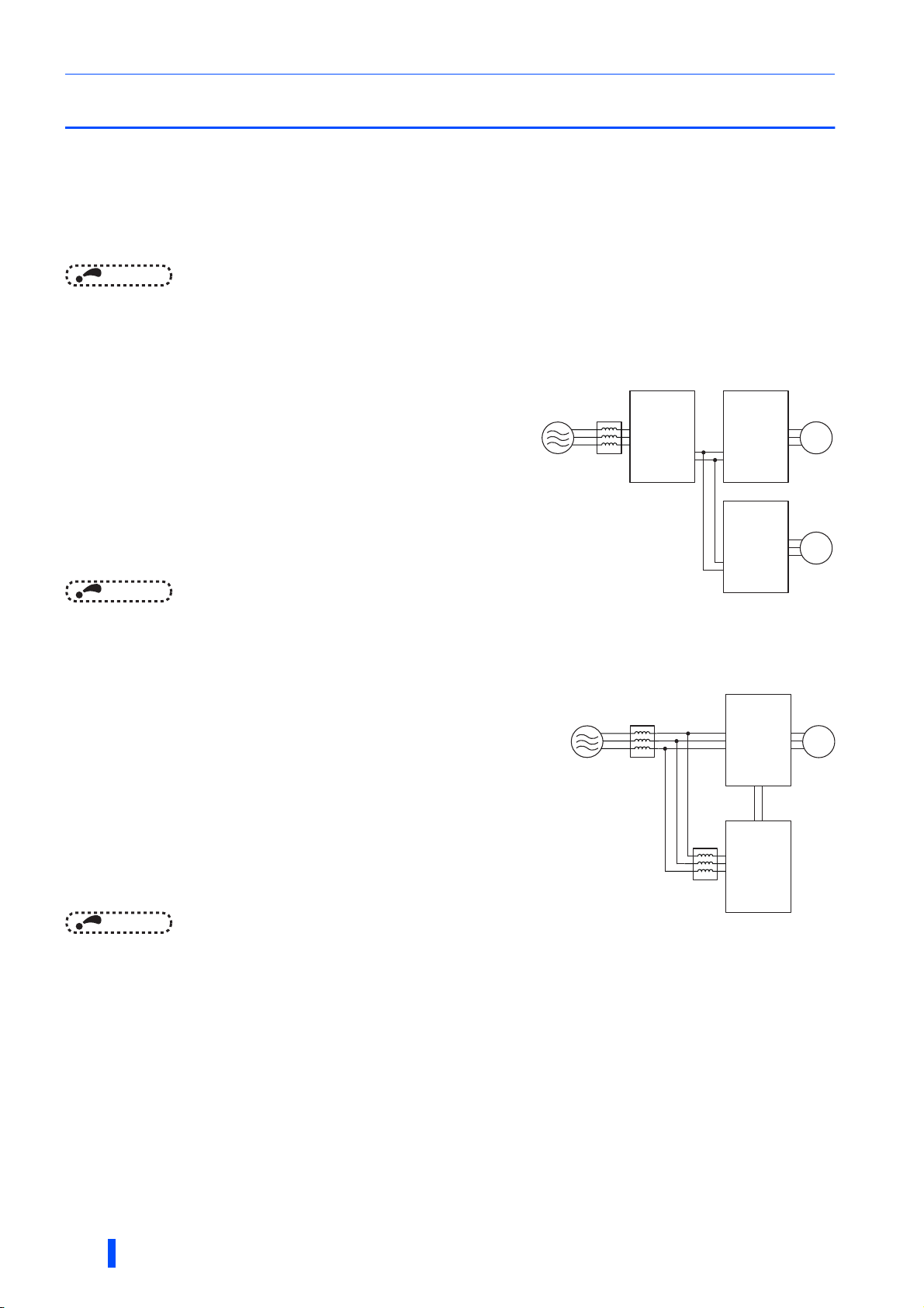
Common bus regeneration mode
Enables continuous regenerative operation at 100% torque. This mode
supports continuous regenerative operations including line operation.
When the converter is connected to multiple inverters, regeneration
energy from an inverter is used for the other inverters. (The FR-XC series
converter can be used as a common converter.) Excessive energy is
returned to the power supply, saving on the energy consumption.
Use the FR-XC series converter in combination with the FR-XCL,
dedicated stand-alone reactor (option).
FR-XCLPower supply
FR-XC
MotorInverter
M
MotorInverter
M
NOTE
• Note that the applicable inverter capacity and current are different if using the FR-XC-(H)18.5K-PWM or FR-XC-(H)22K-PWM
converter with its harmonic suppression function disabled. (Refer to page 156.)
Power regeneration mode
For power driving, the converter section of inverter unit supplies power, and
for regenerative driving, the FR-XC series converter returns power to the
power supply. (The FR-XC series converter cannot be used as a common
converter.)
Since the capacity of power regeneration converter is selectable according to
the regenerative power, the compact and inexpensive power regeneration
converter is applicable when the regenerative power is smaller than the
inverter capacity.
Use the FR-XC series converter in combination with the FR-XCL, dedicated
stand-alone reactor (option).
NOTE
• When installing the converter in a common bus system, do not use the converter in the power regeneration mode.
AC reactor
(FR-HAL)
FR-XCL
Inverter
FR-XC
MotorPower supply
M
8
OUTLINE
Pre-operation instructions
Harmonic suppression
(FR-XC-(H)22K or higher, FR-XC-(H)18.5K-PWM or higher)
The inverter unit has a converter section (rectifier circuit) and generates
power supply harmonics, which may affect the power generator, power
factor correction capacitor, etc. Power supply harmonics are different from
noise and leakage currents in source, frequency band and transmission
path. Power supply harmonics may be suppressed by using the FR-XC
series converter with its harmonic suppression function enabled, allowing
the compliance with the harmonic suppression guidelines issued by the
former Japanese Ministry of International Trade and Industry (currently the
Ministry of Economy, Trade and Industry). The FR-XC series converter with
its harmonic suppression function enabled is classified as the self-excitation
three-phase bridge circuit, and achieves K5 (the conversion factor) = 0. (It is assumed that the FR-XC series converter
generates no harmonics.)
Use the FR-XC series converter in combination with the FR-XCB, dedicated box-type reactor (option).
To enable the harmonic suppression function of the FR-XC-(H)22K or higher, switch to the common bus regeneration mode
and set Pr.416 = "1".
The harmonic suppression function is pre-enabled in the FR-XC-(H)[]K-PWM.
Power supply
FR-XCB
FR-XC
MotorInverter
M
MotorInverter
M
NOTE
• The harmonic suppression function is not available in the power regeneration mode.
• FR-XC-(H)15K or lower does not have the harmonic suppression function.
• Note that the applicable inverter capacity and motor current are different depending on the harmonic suppression function
condition of the FR-XC-(H)22K or FR-XC-(H)30K converter. (Refer to page 156.)
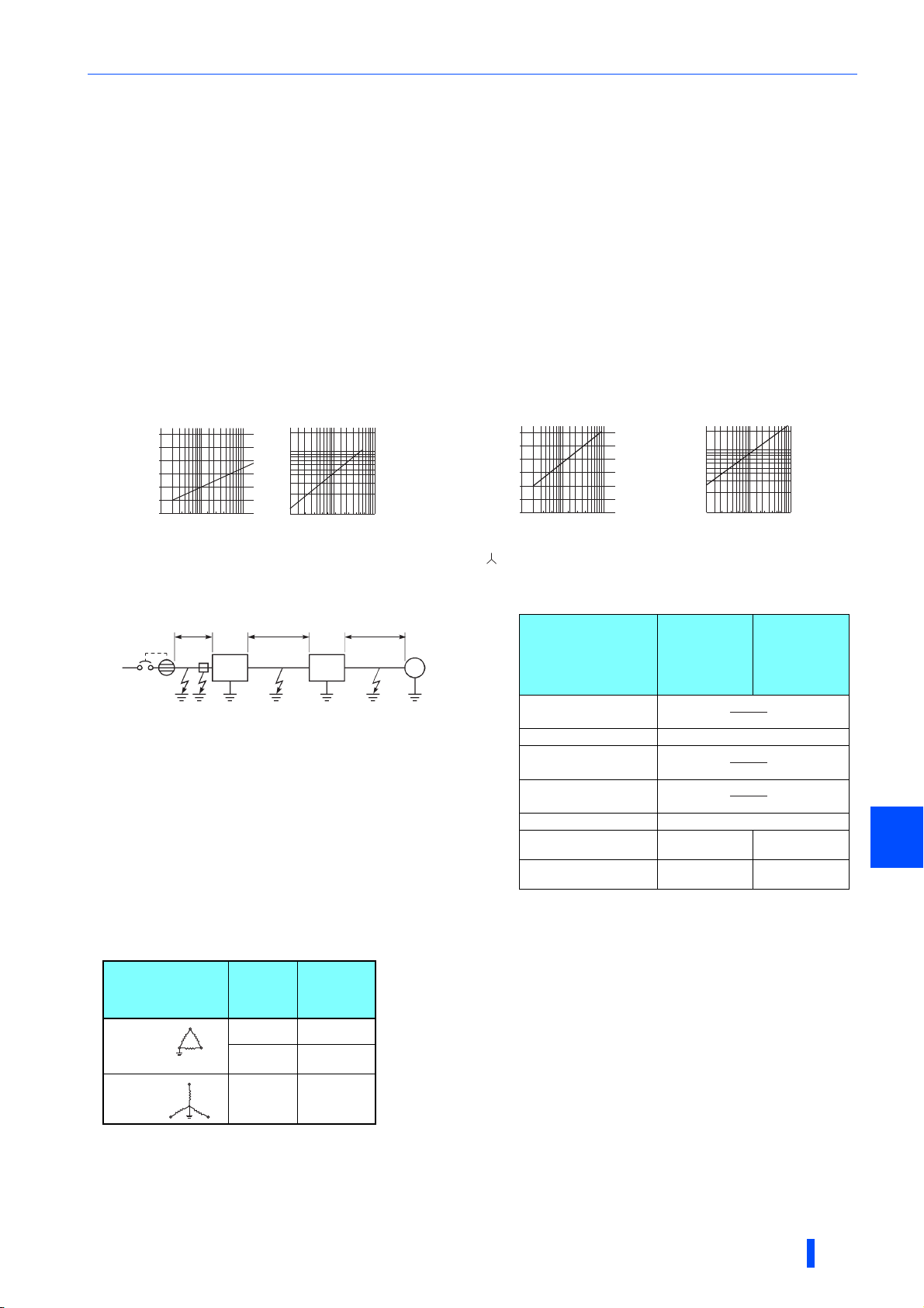
• Power supply harmonic suppression effect
Example of the FR-XC-18.5K-PWM
Condition: Load = 100%
Power factor = 0.99 or more
[Harmonic suppression disabled]
Input phase voltage
Input phase current
[Harmonic suppression enabled]
Input phase voltage
1
Input phase current
NOTE
• It does not mean that harmonic components completely disappear.
• When the load is light, harmonic suppression effect declines.
• When the power supply voltage is unstable, power harmonics flow in, making the harmonic current increase.
Temperature derating selection
By limiting the surrounding air temperature of the multifunction regeneration converter up to 40°C (the surrounding air
temperature of 40°C rating), rated current and applicable current can be increased. (Refer to page 40.)
OUTLINE
9

Pre-operation instructions
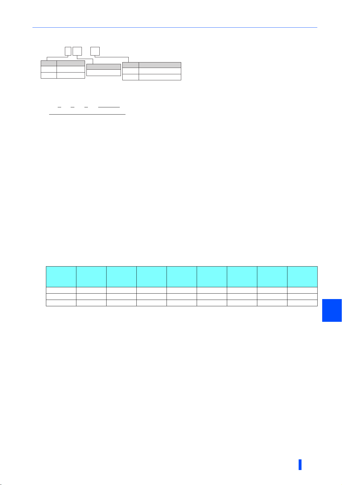
Switch Function
1
ON Common bus regeneration mode
OFF Power regeneration mode
2 For manufacturer setting. (Do not change from ON)
3
ON Surrounding air temperature of 50°C rating
OFF Surrounding air temperature of 40°C rating
4 For manufacturer setting. (Do not change from ON)
1.1.2 Function selection switch assembly (SW2)
The function can be changed by the function selection switches.
NOTE
• The changed switch setting is applied at the next power-ON or converter reset.
• If the switch 1 setting (the connection mode setting) does not match the actual wiring of the main circuit terminals, the
connection mode fault "E.T" occurs.
• By checking the parameter prevents unintended operation of multifunction regeneration converter caused by incorrect setting
of switch. (Refer to page 94.)
•Use Pr.416 Control method selection to enable or disable the harmonic suppression function. (Refer to page 40.)
1.1.3 Product checking and parts identification
Unpack the product and check the rating plate and the capacity plate of the multifunction regeneration converter to ensure
that the model and the rated output agree with the order and the product is intact.
Multifunction regeneration converter model
FR-XC- - 60K
Symbol
None
H 400 V class
Rating plate
Multifunction regeneration
converter model
7.5
Voltage class
200 V class
Capacity plate
Multifunction regeneration
converter model
Input rating
Output rating
SERIAL
Country of origin
PWMH
Converter capacity
Capacity (kW)
SERIAL
‵⁁‿‿⁁⁀‟‿⁁‶‷
∗
⁄‷⁀‹‷⁀‟‿⁁‶‷
FR-XC-22K
ᵡᵭᵬᵴᵣᵰᵲᵣᵰ
FR-XC-22K
›⁅
Symbol Circuit board coating
None Without
60 With
06 With
0$'(,1
Plated conductor
Without
Without
With
Symbol
None
PWM Harmonic suppression enabled
∗1 when Pr.416 = "9999"
Functional specification∗1
Harmonic suppression disabled
The rating for "HS" (Harmonic suppression) is shown on the rating plate of the FR-XC-(H)22K
∗
to 55K and FR-XC-(H)18.5K-PWM to 55K-PWM.
Dedicated stand-alone reactor (option) model
FR-XCL- K
Symbol
None
H 400 V class
10
H
Voltage class
200 V class
OUTLINE
Reactor capacity
Capacity (kW)
Dedicated box-type reactor (option) model
FR-XCB- K-
H
Voltage class
200 V class
H 400 V class
Symbol Circuit board coating
None Without
60 With
Reactor capacity
Capacity (kW)
None
Symbol
How to read the SERIAL number
Pre-operation instructions
Ratingplateexample
Symbol Year Month Control number
SERIAL
The SERIAL consists of one symbol, two characters indicating the
production year and month, and six characters indicating the control number.
The last digit of the production year is indicated as the Year, and the Month is
indicated by 1 to 9, X (October), Y (November), or Z (December).
Accessory
• Earthing (grounding) cable (1)
For connection with a communication option. (Refer to page 71.)
• Communication option LED label (1)
For checking the LED indications on the communication option. (Refer to page 71.)
1.1.4 Harmonic suppression guidelines in Japan
Harmonic currents flow from the inverter to a power receiving point via a power transformer. The Harmonic Suppression
Guidelines was established to protect other consumers from these outgoing harmonic currents.
All capacity and all models of general-purpose inverter used by specific consumers are now covered by "the Harmonic
Suppression Guidelines for Consumers Who Receive High Voltage or Special High Voltage" (hereinafter referred to as
"the Specific Consumer Guidelines").
"Specific Consumer Guidelines"
This guideline sets forth the maximum harmonic currents outgoing from a high-voltage or especially high-voltage receiving
consumer who will install, add or renew harmonic generating equipment. If any of the maximum values is exceeded, this
guideline requires that consumer to take certain suppression measures.
• Maximum values of outgoing harmonic currents per 1 kW contract power
Received
power
voltage
6.6 kV 3.5 2.5 1.6 1.3 1.0 0.9 0.76 0.70
22 kV 1.8 1.3 0.82 0.69 0.53 0.47 0.39 0.36
33 kV 1.2 0.86 0.55 0.46 0.35 0.32 0.26 0.24
5th 7th 11th 13th 17th 19th 23rd Over 23rd
1
OUTLINE
11
Pre-operation instructions
Application of the specific consumer guidelines
Install, add or renew
equipment
Calculation of equivalent
Equal to or less
than reference
capacity
capacity total
Equivalent
capacity total
Above reference
capacity
Calculation of outgoing
harmonic current
Not more than
harmonic current upper
limit?
Equal to or less
than upper limit
Harmonic suppression
measures unnecessary
More than upper limit
Harmonic suppression
measures necessary
• Conversion factor
Classification Circuit type Conversion factor Ki
Without reactor K31 = 3.4
3
5
Three-phase bridge
(capacitor smoothing)
Self-excitation three-phase
bridge
With reactor (AC side) K32 = 1.8
With reactor (DC side) K33 = 1.8
With reactors (AC, DC sides) K34 = 1.4
When a multifunction regeneration converter with
harmonic suppression enabled is used
K5 = 0
• Equivalent capacity limit
Received power voltage Reference capacity
6.6 kV 50 kVA
22/33 kV 300 kVA
66 kV or more 2000 kVA
• Harmonic contents (values of the fundamental current is 100%)
Reactor 5th 7th 11th 13th 17th 19th 23rd 25th
Not used 65 41 8.5 7.7 4.3 3.1 2.6 1.8
Used (AC side) 38 14.5 7.4 3.4 3.2 1.9 1.7 1.3
Used (DC side) 30 13 8.4 5.0 4.7 3.2 3.0 2.2
Used (AC, DC sides) 28 9.1 7.2 4.1 3.2 2.4 1.6 1.4
• Calculation of equivalent capacity P0 of harmonic generating equipment
"Equivalent capacity" is the capacity of a 6-pulse converter converted from the capacity of consumer's harmonic
generating equipment and is calculated by the following equation. If the sum of equivalent capacities is higher than the
limit (refer to page 12), harmonics must be calculated by the equation in next subheading.
P0 = Σ (Ki × Pi) [kVA]
Ki: Conversion factor (Refer to page 12.)
Pi: Rated capacity of harmonic generating equipment
i: Number indicating the conversion circuit type
∗1 [kVA]
∗1 Rated capacity: Determined by the capacity of the
applied motor and found in the following table. The
rated capacity used here is used to calculate the
generated harmonic amount and is different from
the power supply capacity required for actual
inverter drive.
• Calculation of outgoing harmonic currents
Outgoing harmonic currents = fundamental wave current (value converted from received power voltage) × operation
ratio × harmonic contents
• Operation ratio: actual load factor × operation time ratio during 30 minutes
• Harmonic contents: Refer to the list of the harmonic contents.
12
OUTLINE

• Rated capacities and outgoing harmonic currents of inverter-driven motors
Pre-operation instructions
Applicable
motor
(kW)
Fundamental
wave current
(A)
200 V 400 V 5th 7th 11th 13th 17th 19th 23rd 25th
Fundamental
wave
current
converted
from 6.6 kV
Rated
capacity
(kVA)
Outgoing harmonic current converted from 6.6 kV (mA)
(No reactor, 100% operation ratio)
(mA)
0.4 1.61 0.81 49 0.57 31.85 20.09 4.165 3.773 2.107 1.519 1.274 0.882
0.75 2.74 1.37 83 0.97 53.95 34.03 7.055 6.391 3.569 2.573 2.158 1.494
1.5 5.50 2.75 167 1.95 108.6 68.47 14.20 12.86 7.181 5.177 4.342 3.006
2.2 7.93 3.96 240 2.81 156.0 98.40 20.40 18.48 10.32 7.440 6.240 4.320
3.7 13.0 6.50 394 4.61 257.1 161.5 33.49 30.34 16.94 12.21 10.24 7.092
5.5 19.1 9.55 579 6.77 376.1 237.4 49.22 44.58 24.90 17.95 15.05 10.42
7.5 25.6 12.8 776 9.07 504.4 318.2 65.96 59.75 33.37 24.06 20.18 13.97
11 36.9 18.5 1121 13.1 728.7 459.6 95.29 86.32 48.20 34.75 29.15 20.18
15 49.8 24.9 1509 17.6 980.9 618.7 128.3 116.2 64.89 46.78 39.24 27.16
18.5 61.4 30.7 1860 21.8 1209 762.6 158.1 143.2 79.98 57.66 48.36 33.48
22 73.1 36.6 2220 25.9 1443 910.2 188.7 170.9 95.46 68.82 57.72 39.96
30 98.0 49.0 2970 34.7 1931 1218 252.5 228.7 127.7 92.07 77.22 53.46
37 121 60.4 3660 42.8 2379 1501 311.1 281.8 157.4 113.5 95.16 65.88
45 147 73.5 4450 52.1 2893 1825 378.3 342.7 191.4 138.0 115.7 80.10
55 180 89.9 5450 63.7 3543 2235 463.3 419.7 234.4 169.0 141.7 98.10
• Determining if a countermeasure is required
A countermeasure for harmonics is required if the following condition is satisfied: outgoing harmonic currents >
maximum value per 1 kW contract power × contract power.
• Harmonic suppression techniques
No.
Reactor
1
(FR-HAL or FR-HEL)
Multifunction
regeneration
2
converter
(FR-XC series)
Power factor
3
improving capacitor
Transformer multi-
4
phase operation
Passive filter
5
(AC filter)
6 Active filter
Item Description
Install an AC reactor (FR-HAL) on the AC side of the inverter or a DC reactor (FR-HEL) on its DC side,
or install both to suppress outgoing harmonic currents.
The multifunction regeneration converter with harmonic suppression enabled switches the converter
section ON/OFF to reshape an input current waveform into a sine wave, greatly suppressing
harmonics.
Use the FR-XC series converter with the FR-XCB box-type reactor.
When used with a reactor connected in series, the power factor improving correction capacitor can
absorb harmonic currents.
Use two transformers and establish connections with a phase angle difference of 30° (the wye to delta
connection or the delta to delta connection) to provide an effect corresponding to 12 pulses, reducing
low-degree harmonic currents.
A capacitor and a reactor are used together to reduce impedances at specific frequencies. Harmonic
currents are expected to be absorbed greatly by using this technique.
This filter detects the current in a circuit generating a harmonic current and generates a harmonic
current equivalent to a difference between that current and a fundamental wave current to suppress
the harmonic current at the detection point. Harmonic currents are expected to be absorbed greatly by
using this technique.
1
OUTLINE
13
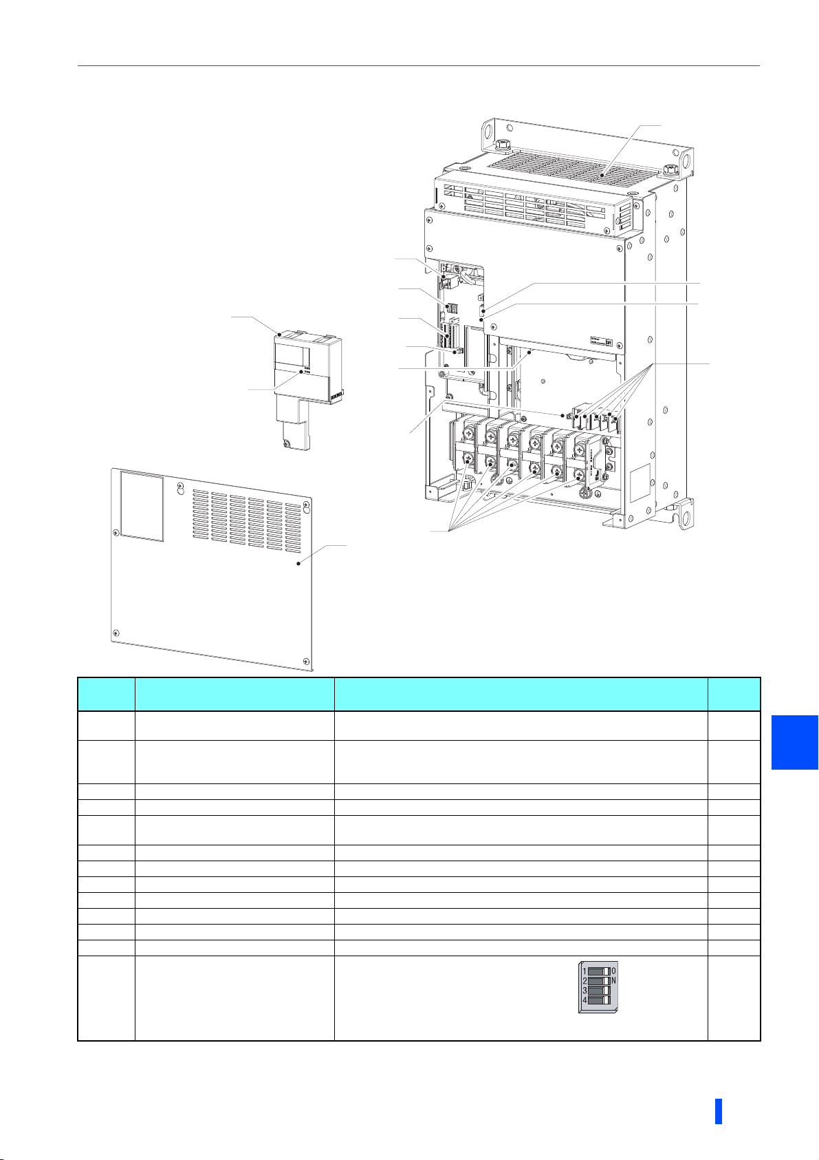
Component names
(d)
(f)
(e)
(h)
(a)
(c)
(l)
(i)
(i)
(i)
(b)
(m)
(k)
(g)
(j)
(i)
1.2 Component names
Component names are shown below.
30K converters or lower
Symbol Name Description
(a) Control circuit terminal block cover
(b)
(c)
(d) PU connector
(e)
(f) Control circuit terminal block Connect cables for the control circuit. 50
(g)
(h) Charge lamp Stays ON while the power is supplied to the main circuit. 72
(i) Main circuit terminal block Connect cables for the main circuit. 41
(j) Connector for manufacturer setting
(k) Cooling fan
(l) Connector for communication option Connect cables for the communication option (FR-A8NC). 71
(m)
Communication operation status
inspection port
(for the FR-A8NC)
Main control circuit terminal block cover
Operation status 7-segment LED
display
Control logic switchover jumper connector
Function selection switch assembly
(SW2)
Remove it for installing a communication option, wiring the control circuit
terminals, or changing the SW2 switches.
Check the state (ON/blinking) of the communication operation status
indicators on the communication option (FR-A8NC) when the option is
installed.
Remove it for wiring. 26
Connector for parameter units. Also used for the RS-485 communication.
Check the display indication or LED state (ON/blinking) for the operation
status of the converter.
Change the control logic of input signals as necessary. 51
Do not remove the cap from the connector.
Cools the multifunction regeneration converter.
1: Connection mode (common bus regeneration mode
/ power regeneration mode) selection
2: For manufacturer setting
3: Temperature derating selection
4: For manufacturer setting
to page
26
⎯
103
72
⎯
149
10
Refer
14
OUTLINE
37K converters or higher
Component names
(k)
(d)
(a)
(b)
(c)
(e)
(f)
(h)
(l)
(m)
(g)
(j)
(i)
(j)
Symbol Name Description
(a) Control circuit terminal block cover
Communication operation status
(b)
(c)
(d) PU connector
(e)
(f) Control circuit terminal block Connect cables for the control circuit. 50
(g)
(h) Charge lamp Stays ON while the power is supplied to the main circuit. 72
(i) Main circuit terminal block Connect cables for the main circuit. 41
(j) Connector for manufacturer setting
(k) Cooling fan
(l) Connector for communication option Connect cables for the communication option (FR-A8NC). 71
(m)
inspection port
(for the FR-A8NC)
Main control circuit terminal block cover
Operation status 7-segment LED
display
Control logic switchover jumper connector
Function selection switch assembly
(SW2)
Remove it for installing a communication option, wiring the control circuit
terminals, or changing the SW2 switches.
Check the state (ON/blinking) of the communication operation status
indicators on the communication option (FR-A8NC) when the option is
installed.
Remove it for wiring. 26
Connector for parameter units. Also used for the RS-485 communication.
Check the display indication or LED state (ON/blinking) for the operation
status of the converter.
Change the control logic of input signals as necessary. 51
Do not remove the cap from the connector.
Cools the multifunction regeneration converter.
1: Connection mode (common bus
regeneration mode / power regeneration
mode) selection
2: For manufacturer setting
3: Temperature derating selection
4: For manufacturer setting
to page
26
⎯
103
72
⎯
149
10
Refer
1
OUTLINE
15
FR-XC series converter and peripheral devices
(Refer to page 60.)
(Refer to page 57.)
(Refer to page 51.)
(Refer to page 21.)
(Refer to page 19.)
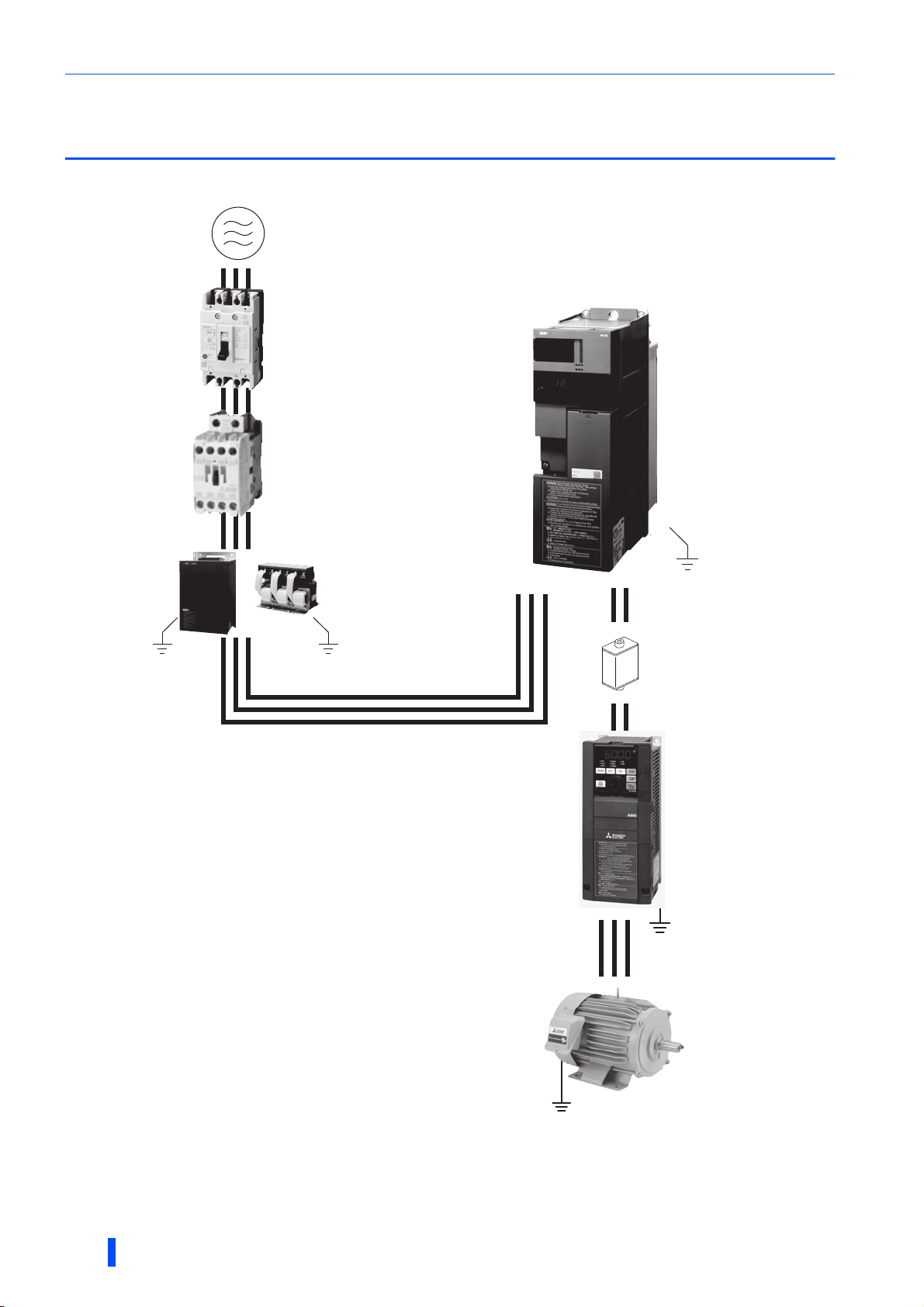
1.3 FR-XC series converter and peripheral
devices
<Example for the common bus regeneration mode>
Three-phase AC power supply
Use power supply within the
permissible specifications of the
converter.
Molded case circuit breaker (MCCB) or
earth leakage circuit breaker (ELB) and fuse
The breaker must be selected carefully since
an inrush current flows in the converter at
power ON.
FR-XC series converter
Install and wire correctly.
Magnetic contactor (MC)
Install the MC to ensure safety.
Do not use this MC to start and stop the
converter and the inverter. Doing so will
shorten the life of the inverter and the
converter.
Do not install a molded case
circuit breaker (MCCB) on the
main circuit cables between the
inverter and the converter
(terminals P to P and terminals N
to N).
Earth (ground)
Dedicated box-type reactor
FR-XCB
(used when harmonic
suppression enabled)
Confirm that the capacity of the
FR-XCB reactor is appropriate
for the capacity of the converter.
Dedicated stand-alone reactor
FR-XCL
(used when harmonic
suppression disabled)
Confirm that the capacity of the
FR-XCL reactor is appropriate for
the capacity of the converter.
Earth (ground)
Devices on the inverter's output side
Do not install a power factor correction capacitor or surge
suppressor or capacitor type filter on the inverter's output
side.
When installing a molded case circuit breaker (MCCB) on
the inverter's output side, contact the manufacturer of
MCCB for MCCB selection.
Earth (ground)
Always earth (ground) the converter, the dedicated reactor
FR-XCL or FR-XCB, the inverter, and the motor.
R2 S2PNT2
Fuse
Installation of a fuse is
recommended for safety. Select a
fuse according to the connected
motor capacity.
Inverter
Select an inverter according to
the capacity of the converter.
The control logic (sink
logic/source logic) of the
converter and the inverter must
be matched.
Earth (ground)
Motor
Earth (ground)
16
Earth (ground)
OUTLINE
Precautions for selecting peripheral devices
Noise propagated
through power supply
cable
…Path (c)
…Path (b)
…Path (a)
Noise directly radiated
from converter
…Path (d), (e)
Air propagated
noise
…Path (f)
Electrical path
propagated noise
…Path (h)
…Path (g)
Multifunction regeneration
converter generated
electromagnetic noise
Electromagnetic
induction noise
Electrostatic
induction noise
Noise radiated from
power supply cable
Noise radiated from
motor connection cable
Noise from earthing
(grounding) cable
due to leakage current
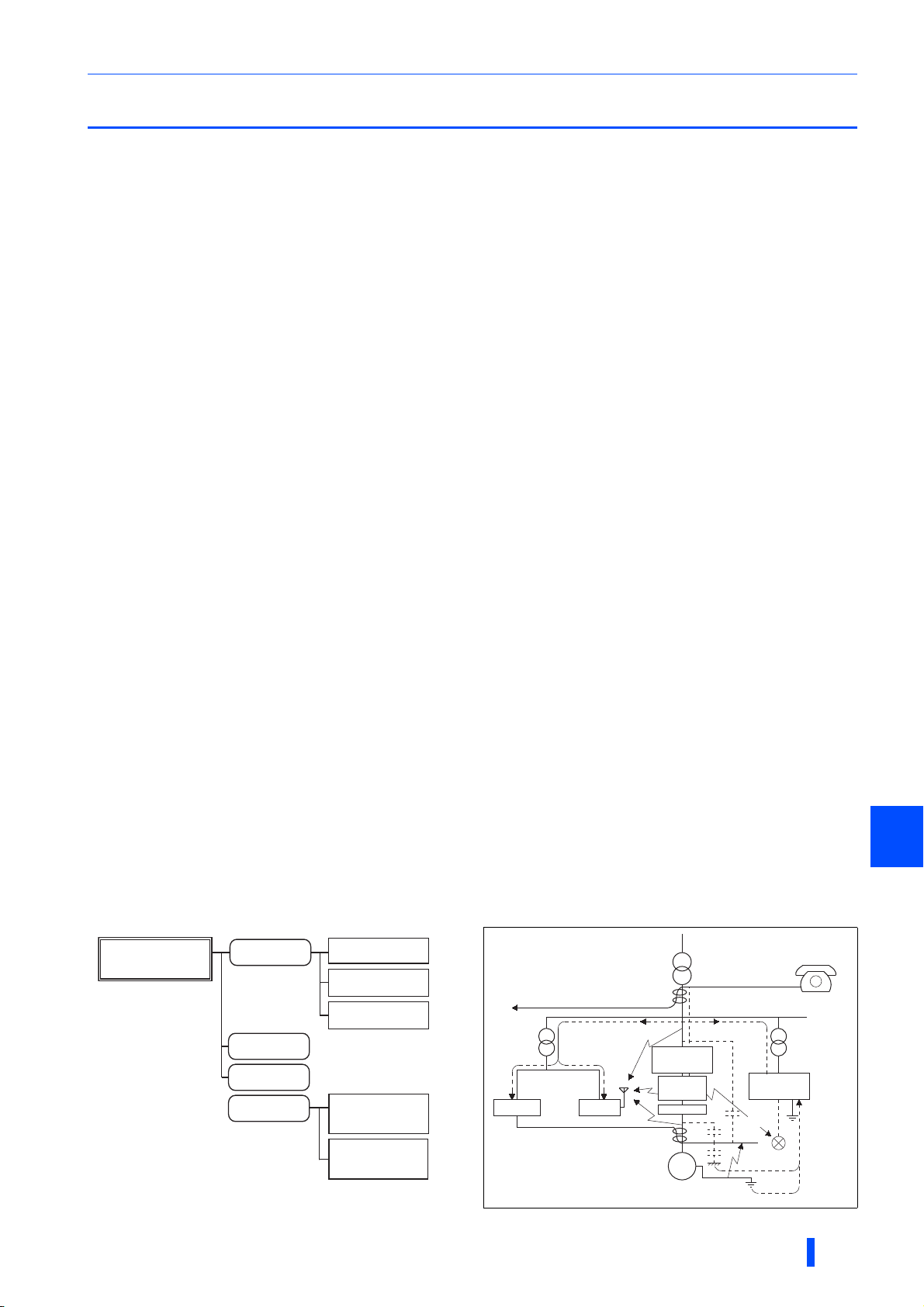
1.4 Precautions for selecting peripheral devices
1.4.1 Techniques and measures for electromagnetic
compatibility (EMC)
Some electromagnetic noises enter the converter to cause the converter malfunction, and others are radiated by the
converter to cause the peripheral devices to malfunction. (The former is called electromagnetic susceptibility (EMS) problem,
the latter is called electromagnetic interference (EMI) problem, and both is called electromagnetic compatibility (EMC)
problem.) Though the FR-XC series converter is designed to be immune to noises, it requires the following basic measures
and EMS measures as it handles low-level signals. Pay attention to the electromagnetic noises that could be generated by the
FR-XC series converter. If these noises cause peripheral devices to malfunction, EMI measures should be taken to suppress
noises. These techniques differ slightly depending on EMI paths.
Basic measures
• Do not run the power cables (I/O cables) and signal cables of the converter in parallel with each other and do not bundle
them.
• Use shielded twisted pair cables for the detector connecting and control signal cables and connect the sheathes of the
shielded cables to terminal SD.
• Ground (earth) the reactor, the converter, the inverter, etc. at one point. (Refer to page 66.)
EMS measures to reduce electromagnetic noises that enter the
When devices that generate many electromagnetic noises (which use magnetic contactors, electromagnetic brakes, many
relays, for example) are installed near the converter and the converter may malfunction due to electromagnetic noises, the
following countermeasures must be taken.
• Provide surge suppressors for devices that generate many electromagnetic noises to suppress electromagnetic noises.
• Install data line filters to signal cables.
• Ground (Earth) the shields of the detector connection and control signal cables with cable clamp metal.
Converter-generated noises are largely classified into those radiated by the converter itself and by the cables (I/O)
connected to its main circuit, those electromagnetically and electrostatically induced to the signal cables of the peripheral
devices close to the power cable connected to the converter main circuit, and those transmitted through the power cables.
converter and cause it to malfunction
EMI measures to reduce electromagnetic noises that are radiated by the
converter to cause the peripheral devices to malfunction
(g)
Instrument Receiver
(b)
(a)
Motor
(e)
Dedicated reactor
or
box-type reactor
Multifunction
regeneration
converter
(c)
Inverter
M
(g)
(d)
(f)
(c)
OUTLINE
Sensor
power supply
(a)
Sensor
Telephone
(h)
1
17
Precautions for selecting peripheral devices
refer to page 66.
Noise
propagation path
(a), (b), (c)
(d), (e), (f)
(g)
(h)
Measure
When devices that handle low-level signals and are liable to malfunction due to electromagnetic noises, e.g.
instruments, receivers and sensors, are contained in the enclosure that contains the converter or when their signal
cables are run near the converter, the devices may malfunction due to by air-propagated electromagnetic noises.
The following measures must be taken:
• Install the easily affected devices as far away from the converter and the inverter as possible.
• Place the easily affected signal cables as far away from the converter and the inverter as possible.
• Do not run signal cables and power cables (converter I/O cables) in parallel with each other and do not bundle
them.
• Install the FR-BLF line noise filter or the FR-BIF radio noise filter on the input side of the converter and install the
FR-BLF on the output side of the inverter to suppress the radiated noise from the cables.
• Use shielded cables as signal cables and power cables, and run them in individual metal conduits, to produce
further effects.
When the signal cables are run in parallel with or bundled with the power cables, magnetic and static induction
noises may be propagated to the signal cables to cause malfunction of the devices. The following measures must
be taken:
• Install the easily affected devices as far away from the converter and the inverter as possible.
• Place the easily affected signal cables as far away from the converter and the inverter as possible.
• Do not run signal cables and power cables (converter I/O cables) in parallel with each other and do not bundle
them.
• Use shielded cables as signal cables and power cables, and run them in individual metal conduits, to produce
further effects.
When the power supplies of the peripheral devices are connected to the power supply of the converter in the same
line, converter-generated noises may flow back through the power supply cables to cause malfunction of the
devices. The following measures must be taken:
• Install the FR-BIF radio noise filter on the input side power cable of the converter.
• Install the FR-BLF line noise filters on the input side power cable of the converter and on the output side power
cable of the inverter.
When a closed loop circuit is formed by connecting the peripheral devices wiring to the converter, leakage currents
may flow through the earthing (grounding) cable of the converter to cause the devices to malfunction. In that case,
disconnecting the earthing (grounding) cables from the devices may stop the malfunction of the devices.
EMI measure example
Power source
for main circuit
For earthing (grounding)
of the converter,
It is preferred that the
inverter, the converter, and
power cables are separated
from sensor circuit by 30 cm
or more (at least 10 cm).
Power source
for control circuit
Decrease the carrier frequency.
Multifunction
regeneration
converter
Inverter
FRBLF
Enclosure
Dedicated reactor
or
box-type reactor
FRBIF
Use a twisted pair shielded cable.
Power supply
for sensor
Do not earth (ground) shield but connect it to signal common cable.
Do not connect earthing (grounding) cables of the sensor directly to the enclosure.
Do not use control cables for earthing (grounding).
Install the filter (FR-BLF/FR-BSF01)
on the inverter output side.
FRBLF
Use a 4-core cable as motor power cable
and use one wire as earth (ground) cable.
Sensor
Motor
M
18
OUTLINE
Precautions for selecting peripheral devices
1.4.2 Peripheral device list
Circuit breaker and magnetic contactor
Check the model of the purchased multifunction regeneration converter. Appropriate peripheral devices must be selected
according to the capacity.
Common bus regeneration mode
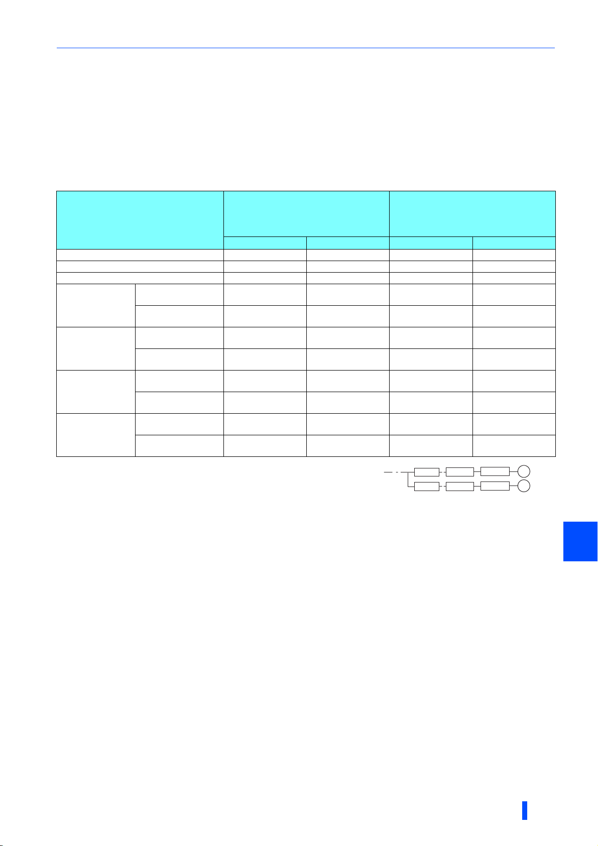
For the converter in common bus regeneration mode, refer to the following table to prepare appropriate peripheral
devices.
• 200 V class
Molded case circuit breaker
(MCCB)∗1/
FR-XC series converter model
earth leakage circuit breaker (ELB)
(NF, NV type)
50°C rating 40°C rating 50°C rating 40°C rating
FR-XC-7.5K 60 A 60 A S-T35 S-T35
FR-XC-11K 75 A 75 A S-T35 S-T35
FR-XC-15K 125 A 125 A S-T50 S-T50
FR-XC-22K
FR-XC-18.5K-PWM
FR-XC-30K
FR-XC-22K-PWM
FR-XC-37K
FR-XC-37K-PWM
FR-XC-55K
FR-XC-55K-PWM
∗1 Select an MCCB according to the power supply capacity.
Install one MCCB per converter.
(For the use in the United States or Canada, refer to page 179.)
∗2 The magnetic contactor is selected based on the AC-1 class. The electrical durability of
magnetic contactor is 100,000 times. When the magnetic contactor is used for emergency stops during motor driving, the electrical durability is
25 times.
If using an MC for emergency stop during motor driving or using it on the motor side during commercial power supply operation, select an MC
with the class AC-3 rated current for the rated motor current.
Harmonic suppression
disabled
Harmonic suppression
enabled
Harmonic suppression
disabled
Harmonic suppression
enabled
Harmonic suppression
disabled
Harmonic suppression
enabled
Harmonic suppression
disabled
Harmonic suppression
enabled
175 A 175 A S-T65 S-T80
125 A 125 A S-T50 S-T50
225 A 225 A S-T100 S-T100
125 A 125 A S-T65 S-T65
250 A 250 A S-N150 S-N150
200 A 200 A S-T100 S-N150
400 A 400 A S-N180 S-N180
300 A 300 A S-N180 S-N180
Magnetic contactor (MC)∗2
MCCB
MCCB
FR-XC
FR-XC
Inverter
Inverter
M
M
OUTLINE
1
19
Precautions for selecting peripheral devices
• 400 V class
Molded case circuit breaker
(MCCB)∗1/
FR-XC series converter model
earth leakage circuit breaker (ELB)
(NF, NV type)
50°C rating 40°C rating 50°C rating 40°C rating
FR-XC-H7.5K 30 A 30 A S-T21 S-T21
FR-XC-H11K 50 A 50 A S-T21 S-T21
FR-XC-H15K 60 A 60 A S-T35 S-T35
FR-XC-H22K
FR-XC-H18.5KPWM
FR-XC-H30K
FR-XC-H22K-PWM
FR-XC-H37K
FR-XC-H37K-PWM
FR-XC-H55K
FR-XC-H55K-PWM
Harmonic suppression
disabled
Harmonic suppression
enabled
Harmonic suppression
disabled
Harmonic suppression
enabled
Harmonic suppression
disabled
Harmonic suppression
enabled
Harmonic suppression
disabled
Harmonic suppression
enabled
100 A 100 A S-T35 S-T35
60 A 60 A S-T35 S-T35
125 A 125 A S-T50 S-T50
75 A 75 A S-T35 S-T35
150 A 150 A S-T65 S-T65
100 A 100 A S-T50 S-T65
200 A 200 A S-T100 S-T100
150 A 150 A S-T80 S-T80
Magnetic contactor (MC)∗2
∗1 Select an MCCB according to the power supply capacity.
Install one MCCB per converter.
(For the use in the United States or Canada, refer to page 179.)
∗2 The magnetic contactor is selected based on the AC-1 class. The electrical durability of
magnetic contactor is 100,000 times. When the magnetic contactor is used for emergency stops during motor driving, the electrical durability is
25 times.
If using an MC for emergency stop during motor driving or using it on the motor side during commercial power supply operation, select an MC
with the class AC-3 rated current for the rated motor current.
MCCB
MCCB
FR-XC
FR-XC
Inverter
Inverter
Power regeneration mode
To use the converter in power regeneration mode, select a circuit breaker and a magnetic contactor (MC) for the inverter
according to the inverter capacity. For details, refer to the Instruction Manual of each inverter.
Additionally, install a molded case circuit breaker (MCCB) or earth leakage circuit breaker (ELB) with the rating shown in
the following table on the input side of the FR-XCL reactor. For the information of the installation location, refer to page 58.
• 200 V class
FR-XC series
converter model
FR-XC-7.5K 50 A
FR-XC-11K 60 A
FR-XC-15K 75 A
FR-XC-22K
FR-XC-18.5K-PWM
FR-XC-30K
FR-XC-22K-PWM
FR-XC-37K
FR-XC-37K-PWM
FR-XC-55K
FR-XC-55K-PWM
Molded case circuit breaker (MCCB)/
earth leakage circuit breaker (ELB)
125 A
175 A
200 A
250 A
(NF, NV type)
M
M
20
OUTLINE
Precautions for selecting peripheral devices
• 400 V class
FR-XC series
converter model
FR-XC-H7.5K 30 A
FR-XC-H11K 30 A
FR-XC-H15K 40 A
FR-XC-H22K
FR-XC-H18.5K-PWM
FR-XC-H30K
FR-XC-H22K-PWM
FR-XC-H37K
FR-XC-H37K-PWM
FR-XC-H55K
FR-XC-H55K-PWM
Molded case circuit breaker (MCCB)/
earth leakage circuit breaker (ELB) (NF, NV type)
75 A
100 A
125 A
150 A
NOTE
• If any breaker trips, check for the wiring fault (such as short circuit), damage to internal parts of the multifunction regeneration
converter, etc. The cause of the trip must be identified and removed before turning ON the power of the breaker.
Fuse
Installation of a fuse between the multifunction regeneration converter and the inverter is recommended.
When using the converter in the common bus regeneration mode, select a fuse according to the capacity of the connected
motor. When using a motor whose capacity is smaller than the inverter capacity by two ranks or more, select the fuse with the
capacity that is one rank lower than the inverter capacity.
When using the converter in power regeneration mode, select a fuse according to the capacity of the converter.
(Refer to page 60 for wiring between the converter and the inverter.)
Common bus regeneration mode
• 200 V class
Motor capacity
(kW)
0.1 5 6.900 CP GR 10.38 0005 (FR10GR69V5)
0.2 10 6.900 CP GR 10.38 0010 (FR10GR69V10)
0.4 16 6.900 CP GR 10.38 0016 (FR10GR69V16)
0.75 20 6.900 CP GR 10.38 0020 (FR10GR69V20)
1.5 25 6.900 CP GR 10.38 0025 (FR10GR69V25)
2.2 50 6.9 URD 30 TTF 0050 —
3.7 63 6.9 URD 30 TTF 0063 —
5.5 100 6.9 URD 30 TTF 0100 —
7.5 125 6.9 URD 30 TTF 0125 —
11 160 6.9 URD 30 TTF 0160 —
15 200 6.9 URD 30 TTF 0200 —
18.5 250 6.9 URD 30 TTF 0250 —
22 315 6.9 URD 30 TTF 0315 —
30 400 6.9 URD 30 TTF 0400 —
37 500 6.9 URD 30 TTF 0500 —
45 630 6.9 URD 31 TTF 0630 —
55 700 6.9 URD 31 TTF 0700 —
• 400 V class
Motor capacity
(kW)
0.4 12.5 6.900 CP GR 10.38 0012.5 (FR10GR69V12.5)
0.75 16 6.900 CP GR 10.38 0016 (FR10GR69V16)
1.5 16 6.900 CP GR 10.38 0016 (FR10GR69V16)
2.2 20 6.900 CP GR 10.38 0020 (FR10GR69V20)
3.7 30 6.900 CP GR 10.38 0030 (FR10GR69V30)
5.5 50 6.9 URD 30 TTF 0050 —
7.5 50 6.9 URD 30 TTF 0050 —
11 80 6.9 URD 30 TTF 0080 —
15 125 6.9 URD 30 TTF 0125 —
18.5 125 6.9 URD 30 TTF 0125 —
22 160 6.9 URD 30 TTF 0160 —
30 200 6.9 URD 30 TTF 0200 —
37 250 6.9 URD 30 TTF 0250 —
45 315 6.9 URD 30 TTF 0315 —
55 350 6.9 URD 30 TTF 0350 —
Fuse rating (A) Model∗1 Fuse holder (2 poles)
Fuse rating (A) Model∗1 Fuse holder (2 poles)
US102 (without fuse light melting indicator)
or US102I (with fuse light melting indicator)
1
US102 (without fuse light melting indicator)
or US102I (with fuse light melting indicator)
OUTLINE
21
Precautions for selecting peripheral devices
Power regeneration mode
• 200 V class
FR-XC series
converter
capacity (kW)
FR-XC-7.5K 125 6.9 URD 30 TTF 0125 —
FR-XC-11K 160 6.9 URD 30 TTF 0160 —
FR-XC-15K 200 6.9 URD 30 TTF 0200 —
FR-XC-22K
FR-XC-18.5K-PWM
FR-XC-30K
FR-XC-22K-PWM
FR-XC-37K
FR-XC-37K-PWM
FR-XC-55K
FR-XC-55K-PWM
• 400 V class
FR-XC series
converter capacity
(kW)
FR-XC-H7.5K 50 6.9 URD 30 TTF 0050 —
FR-XC-H11K 80 6.9 URD 30 TTF 0080 —
FR-XC-H15K 125 6.9 URD 30 TTF 0125 —
FR-XC-H22K
FR-XC-H18.5K-PWM
FR-XC-H30K
FR-XC-H22K-PWM
FR-XC-H37K
FR-XC-H37K-PWM
FR-XC-H55K
FR-XC-H55K-PWM
Fuse rating (A) Model∗1 Fuse holder (2 poles)
315 6.9 URD 30 TTF 0315 —
400 6.9 URD 30 TTF 0400 —
500 6.9 URD 30 TTF 0500 —
700 6.9 URD 31 TTF 0700 —
Fuse rating (A) Model∗1 Fuse holder (2 poles)
160 6.9 URD 30 TTF 0160 —
200 6.9 URD 30 TTF 0200 —
250 6.9 URD 30 TTF 0250 —
350 6.9 URD 30 TTF 0350 —
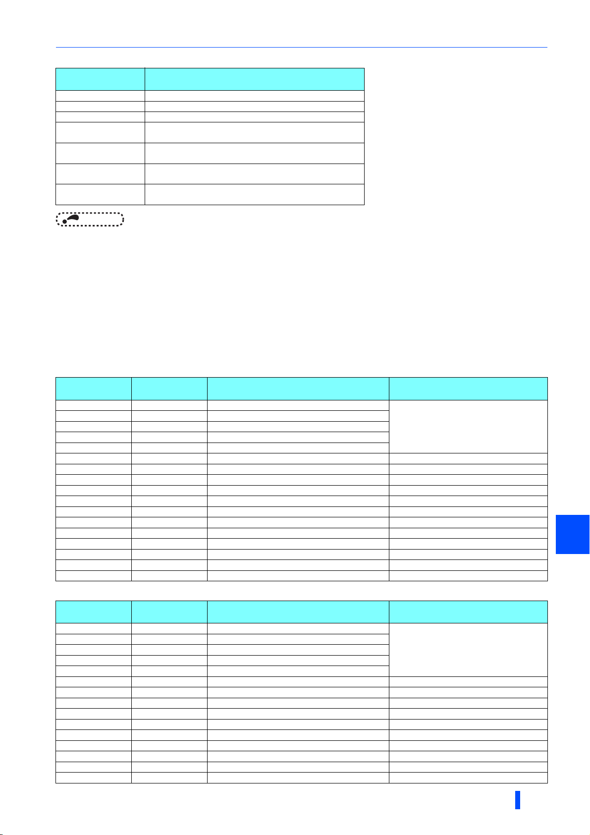
∗1 Manufacturer: Mersen Japan KK
Contact: Sun-Wa Technos Corporation
NOTE
• Install fuses across terminals P/+ and P/+, and across terminals N/- and N/- of the multifunction regeneration converter and
the inverter.
[Estimated lifespan of fuses]
Components Estimated lifespan∗1 Replacement method
Fuse 10 years Replace by new one
∗1 Estimated lifespan for when the yearly average surrounding air temperature is 50°C. (without corrosive gas, flammable gas, oil mist, dust and
dirt etc.)
NOTE
• If the fuse melts down, wiring failure such as a short circuit may be the cause. Find out the cause and remove it before
replacing the fuse.
22
OUTLINE
Precautions for selecting peripheral devices
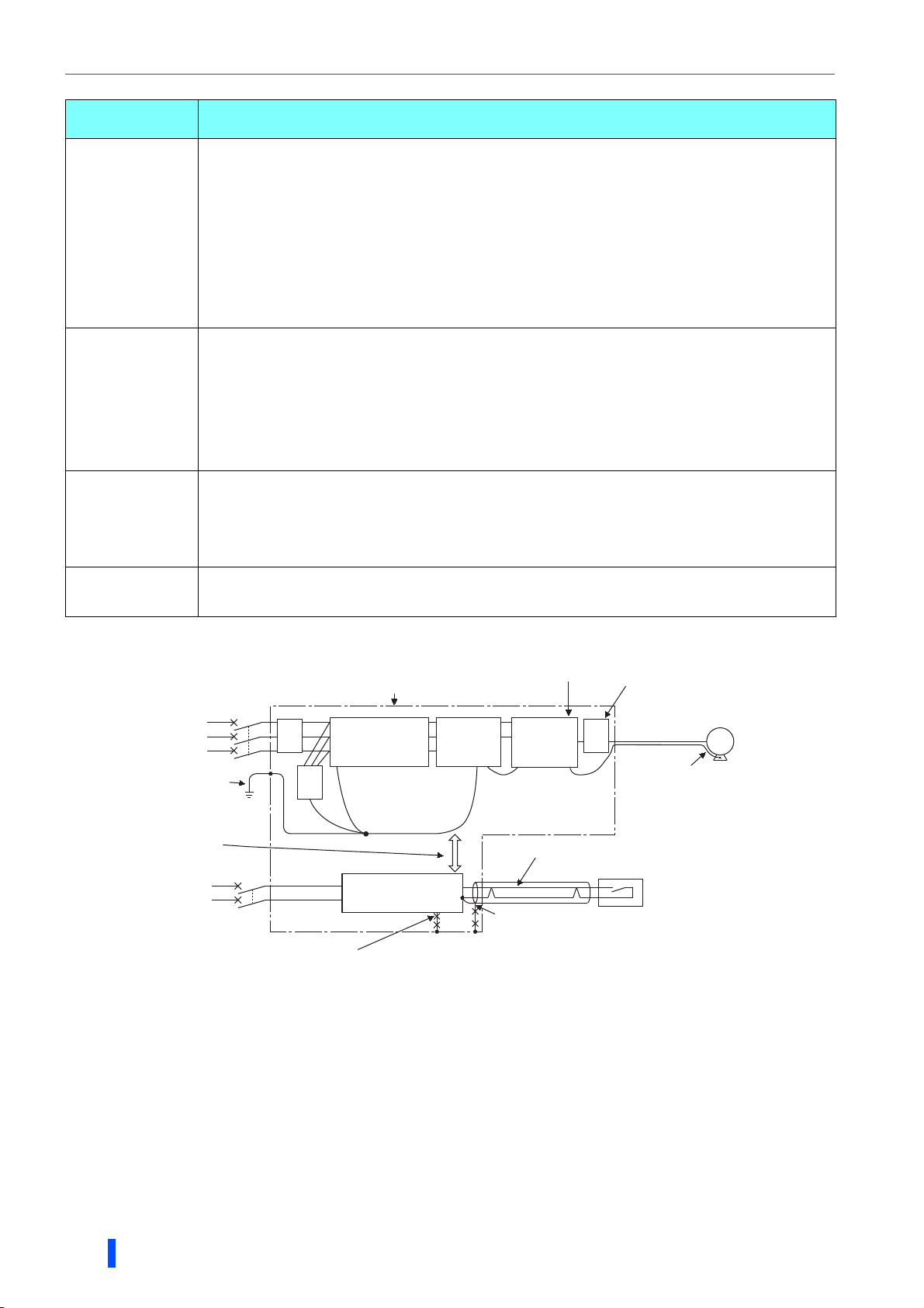
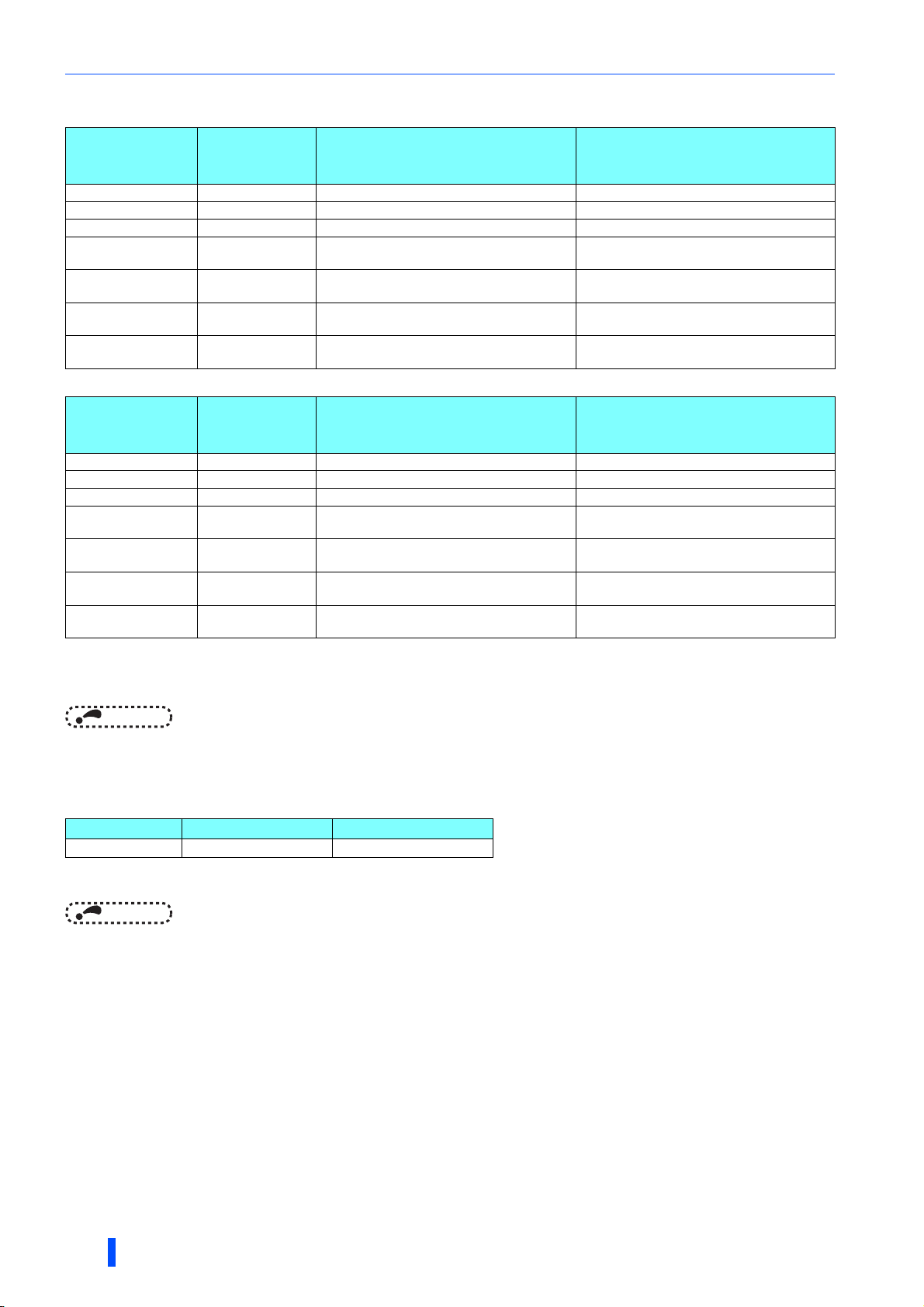
Ig1, lg2, lg3: Leakage currents in wire path during
commercial power supply operation
Ign: Leakage current from noise filters on the input side
of the converter
Igm: Leakage current from the motor during
commercial power supply operation
Selection example (diagram shown on the left) (mA)
Breaker
designed for
harmonic and
surge
suppression
Standard
breaker
Leakage current lg1 (mA)
33 × = 0.17
Leakage current lgn (mA) 0 (without noise filter)
Leakage current lg2 (mA)
33 × = 0.17
Leakage current lg3 (mA)
33 × = 2.31
Leakage current lgm (mA) 0.18
Total leakage current
(mA)
2.83 7.81
Rated sensitivity current
(≥ Ig × 10) (mA)
30 100
1.4.3 Selecting the rated sensitivity current for the
earth leakage circuit breaker
To install the earth leakage circuit breaker on the inverter circuit, select its rated sensitivity current as follows.
• Breaker designed for harmonic and surge suppression
Rated sensitivity current
I∆n ≥ 10 × (Ig1 + Ign + Ig2 + Ig3 + Igm)
• Standard breaker
Rated sensitivity current
I∆n ≥ 10 × {Ig1 + Ign + Ig2 + 3 × (Ig3 + Igm)}
Example of leakage current of
cable path per 1km during the
commercial power supply operation
when the CV cable is routed in
metal conduit
(200 V 60 Hz) (200 V 60 Hz)
120
100
80
60
40
20
[Example]
0
Leakage currents (mA)
2 3.5
8142230386080
5.5
Cable size (mm2)
2
5.5 mm
×5 m
ELB
Noise
filter
FR-XC
converter
Leakage currents (mA)
150
100
5.5 mm2×5 m 5.5 mm2×70 m
lg1 lgn lg2 lg3
Leakage current example of
three-phase induction motor
during the commercial
power supply operation
2. 0
1. 0
0. 7
0. 5
0. 3
0. 2
0. 1
1. 5 3.7
7. 5 152211373055
2. 2
Motor capacity (kW)
Inverter
455.5 18. 5
3φ
IM
200 V 2.2 kW
lgm
Example of leakage current per 1km during
the commercial power supply operation
when the CV cable is routed in metal conduit
(Three-phase three-wire delta
connection 400 V 60 Hz)
120
100
80
60
40
20
0
2 3.5
8142230386080
size (mm2)
100
150
Leakage currents (mA)
For " " connection, the amount of leakage current is appox.1/3 of the above value.
5.5
Cable
Leakage current example of threephase induction motor during the
commercial power supply operation
(Totally-enclosed fan-cooled
type motor 400 V 60 Hz)
2. 0
1. 0
0. 7
0. 5
0. 3
0. 2
0. 1
1. 5 3.7
Leakage currents (mA)
7. 5 152211373055
2. 2
Motor capacity (kW)
455.5 18. 5
5 m
1000 m
5 m
1000 m
70 m
1000 m
• Multifunction regeneration converter leakage current
Input power conditions
: 220 V/60 Hz (200 V class) or 440 V/60 Hz (400 V class), within 3% of power supply unbalance
Voltage
(V)
Leakage
current
Phase
earthing
(grounding)
Earthed-neutral
system
200 2
400 4
400 4
(mA)
OUTLINE
1
23

Precautions for selecting peripheral devices
NOTE
• Install the earth leakage circuit breaker (ELB) on the input side of the converter.
• In the connection earthed-neutral system, the sensitivity current is blunt against a ground fault in the inverter output side.
Earthing (Grounding) must conform to the requirements of national and local safety regulations and electrical codes. (NEC
section 250, IEC 61140 class 1 and other applicable standards)
• Do not install the breaker on the output side of the inverter. Doing so may cause unnecessarily operations by harmonics even
if the effective value is within the rating, since the eddy current and hysteresis loss will increase, leading to temperature rise.
• The following models are included in the standard breakers: the BV-C1, BC-V, NVB, NV-L, NV-G2N, NV-G3NA, and NV-2F
earth leakage relay (except NV-ZHA) and the NV class earth leakage circuit breaker with AA neutral wire open-phase
protection.
The following models are designed for harmonic and surge suppression: NV-C/NV-S/MN series, NV30-FA, NV50-FA, BV-C2,
earth leakage alarm breaker (NF-Z), NV-ZHA, and NV-H.
24
OUTLINE

2 INSTALLATION AND
WIRING
Thischapterexplainstheinstallationandthewiringofthisproduct.
Alwaysreadtheinstructionsbeforeuse.
2.1 Removal and reinstallation of the converter covers .............26
2.2 Removal and reinstallation of the FR-XCB reactor cover .....28
2.3 Installation of the converter and enclosure design...............29
2.4 Installation of peripheral devices ............................................36
2.5 Connection of the converter and the inverter ........................38
2.6 Main circuit terminal specification ..........................................41
2.7 Control circuit specification ....................................................50
2.8 Wiring.........................................................................................57
2.9 Earthing (Grounding) precautions ..........................................66
2.10 Connection of the converter and the multiple inverters .......67
2.11 PU installation on converter ....................................................70
2.12 Communication operation .......................................................71
2.13 Before powering and starting operation.................................72
2.14 Digital characters and their corresponding printed
equivalents ................................................................................73
2
INSTALLATION AND WIRING
25
Removal and reinstallation of the converter covers
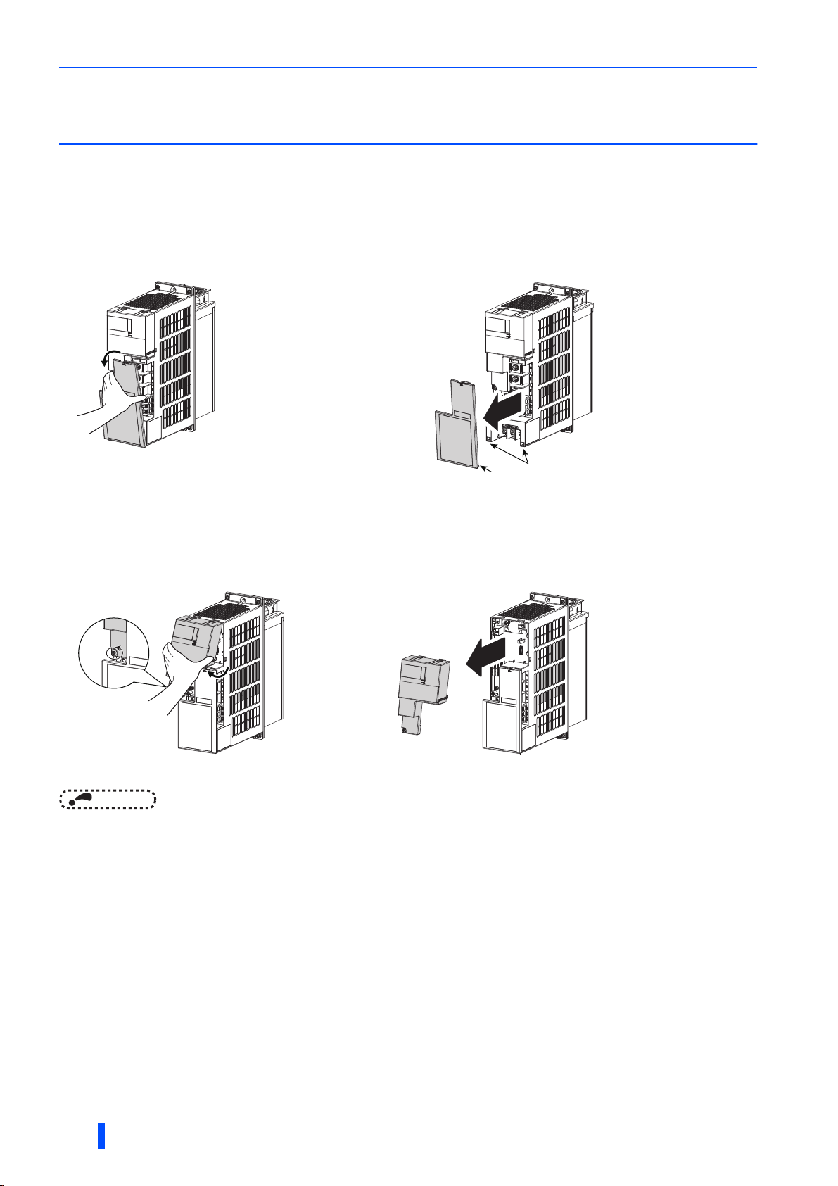
2.1 Removal and reinstallation of the converter
covers
2.1.1 30K converters or lower
Main circuit terminal block cover
• To remove the cover, hold and pull out the upper part of
the cover.
To reinstall the cover, insert the hooks into the slots on the converter and push the cover to snap it into place.
• The hooks on the lower end of the cover snap out of
position. The cover is detached from the converter.
Slot
Hook
Control circuit terminal block cover
• To remove the cover, loosen the mounting screws of the
cover, and hold and pull out the lower part of the cover.
• The hooks on the upper end of the cover snap out of
position. The cover is detached from the converter.
To reinstall the cover, insert the hooks into the slots on the converter and push the cover to snap it into place.
NOTE
• After installing the cover, check that it is fixed securely in place. Always tighten the mounting screws of the cover.
26
INSTALLATION AND WIRING
Removal and reinstallation of the converter covers
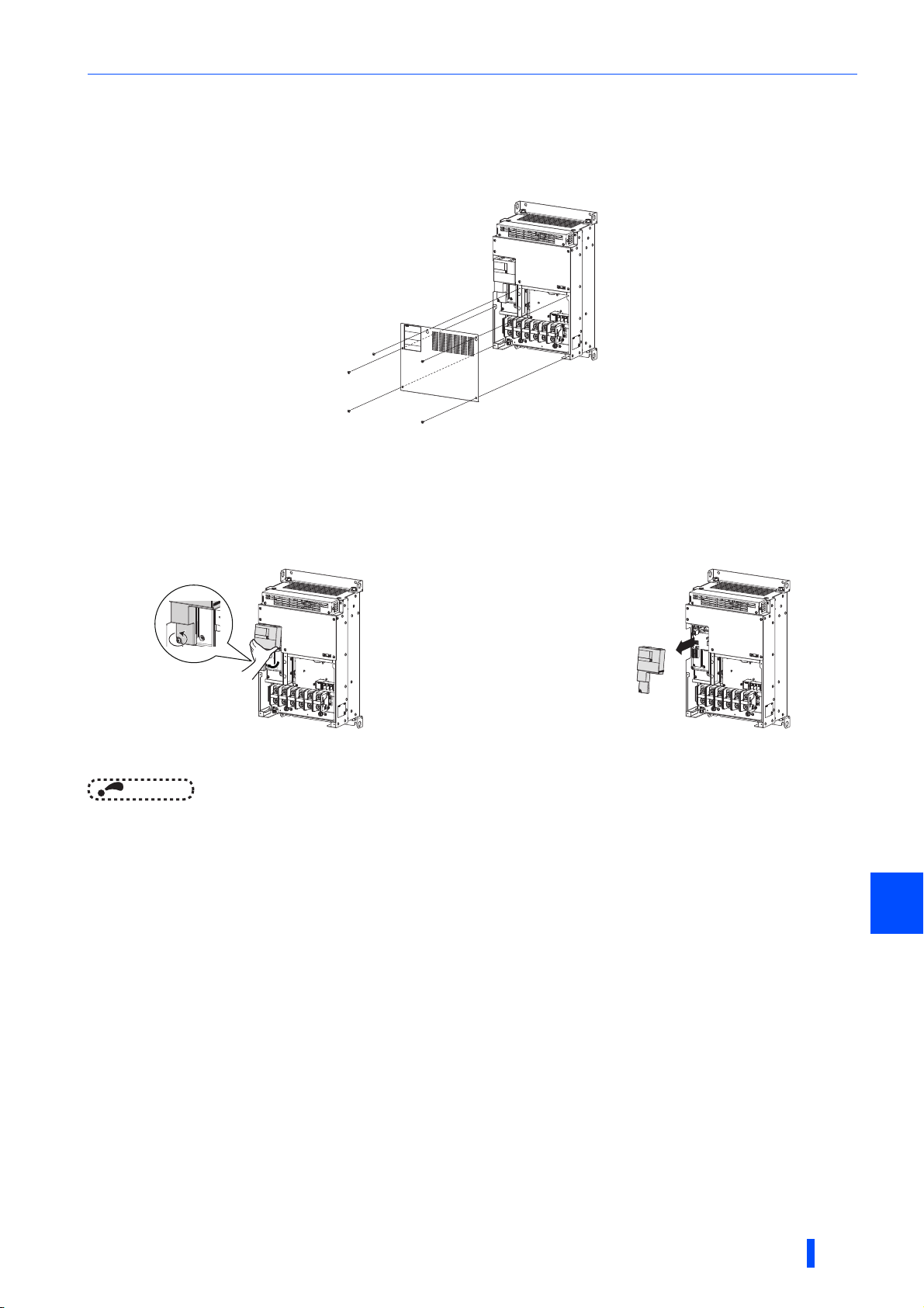
2.1.2 37K converters or higher
Main circuit terminal block cover
• When the mounting screws are removed, the main circuit terminal block cover can be removed.
To reinstall the cover, insert the hooks into the slots on the converter and push the cover to snap it into place.
Control circuit terminal block cover
• To remove the cover, loosen the mounting screws of the
cover, and hold and pull out the lower part of the cover.
To reinstall the cover, insert the hooks into the slots on the converter and push the cover to snap it into place.
NOTE
• After installing the cover, check that it is fixed securely in place. Always tighten the mounting screws of the cover.
• The hooks on the upper end of the cover snap out of
position. The cover is detached from the converter.
2
INSTALLATION AND WIRING
27
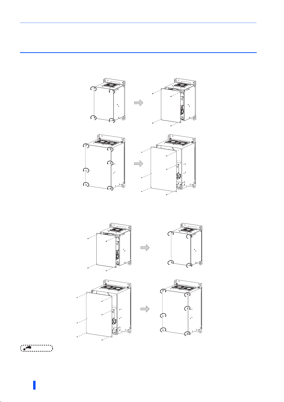
Removal and reinstallation of the FR-XCB reactor cover
2.2 Removal and reinstallation of the FR-XCB
reactor cover
Removal
• Loosen the mounting screws of the cover. • Pull out the cover to remove it.
●FR-XCB-(H)18.5K, 22K
Cover
●FR-XCB-(H)37K or higher
Cover
Reinstallation
• Align the screw holes on the cover with the holes on the
reactor, and place the cover back into position.
●FR-XCB-(H)18.5K, 22K
Cover
Cover
• Tighten the mounting screws of the cover (tightening
torque: 1.7 Nm).
Cover
●FR-XCB-(H)37K or higher
Cover
Cover
Cover
NOTE
• After installing the front cover, check that it is fixed securely in place. Always tighten the mounting screws of the cover.
• The capacity plate is placed on the cover, and the rating plate is on the remainder of the reactor box. Before reinstalling the
cover, check the serial number on the capacity plate against the one on the rating plate to make sure they are identical with
each other.
28
INSTALLATION AND WIRING
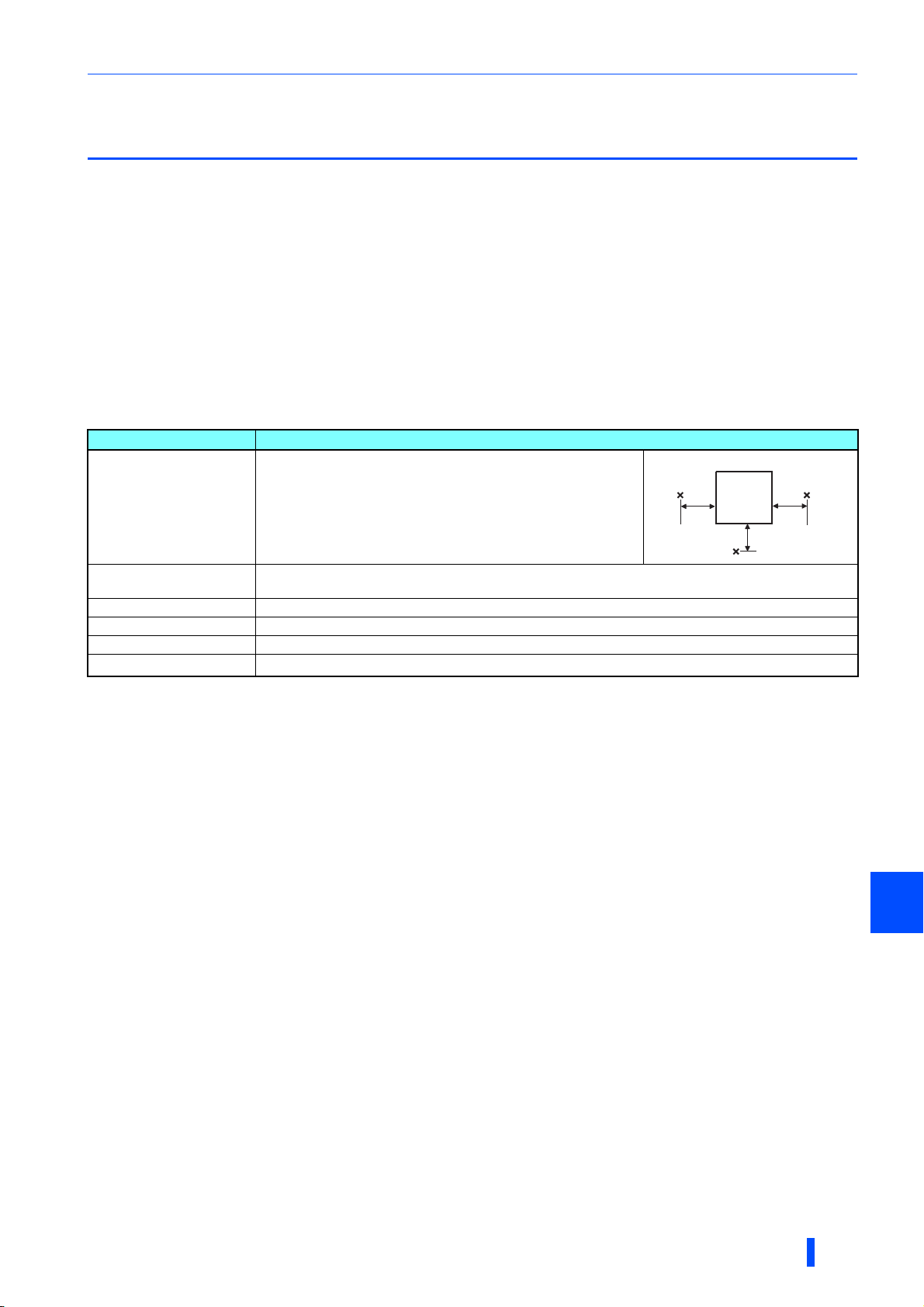
Installation of the converter and enclosure design
2.3 Installation of the converter and enclosure
design
When designing or manufacturing an enclosure, determine the structure, size, and device layout of the enclosure by fully
considering the conditions such as heat generation of the contained devices and the operating environment.
The multifunction regeneration converter unit uses many semiconductor devices. To ensure higher reliability and long period
of operation, operate the converter in the ambient environment that completely satisfies the equipment specifications.
2.3.1 Converter installation environment
The following table lists the standard specifications of the installation environment for the multifunction regeneration converter.
Using the converter in an environment that does not satisfy the conditions deteriorates the performance, shortens the life, and
causes a failure. Refer to the following points, and take adequate measures.
Standard environmental specifications of the converter
Item Description
Measurement
position
5 cm
Surrounding air temperature -10 to +50°C∗1 (non-freezing)
5 cm
Converter
5 cm
Ambient humidity
Storage temperature -20 to +65°C
Atmosphere Indoors (free from corrosive gas, flammable gas, oil mist, dust and dirt)
Altitude Maximum 2500 m
Vibration
∗1 -10 to +40°C (non-freezing) at the 40°C rating.
∗2 Temperature applicable for a short time, for example, in transit.
∗3 For the installation at an altitude above 1000 m, consider a 3% reduction in the rated current per 500 m increase in altitude.
With circuit board coating (conforming to IEC 60721-3-3 3C2/3S2): 95% RH or less (non-condensing)
Without circuit board coating: 90% RH or less (non-condensing)
∗2
∗3
2
5.9 m/s
or less at 10 to 55 Hz (directions of X, Y, Z axes)
Measurement
position
Temperatur e
The permissible surrounding air temperature of the multifunction regeneration converter is -10 to +50°C (-10 to +40°C at the
40°C rating). Always operate the converter within this temperature range. Operation outside this range will considerably
shorten the service lives of the semiconductors, parts, capacitors and others. Take the following measures to keep the
surrounding air temperature of the converter within the specified range.
(a) Measures against high temperature
• Use a forced ventilation system or similar cooling system. (Refer to page 31.)
• Install the enclosure in an air-conditioned electric chamber.
• Block direct sunlight.
• Provide a shield or similar plate to avoid direct exposure to the radiated heat and wind of a heat source.
• Ventilate the area around the enclosure well.
(b) Measures against low temperature
• Provide a space heater in the enclosure.
• Do not power OFF the converter. (Keep the start signal of the inverter OFF.)
(c) Sudden temperature changes
• Select an installation place where temperature does not change suddenly.
• Avoid installing the converter near the air outlet of an air conditioner.
• If temperature changes are caused by opening/closing of a door, install the converter away from the door.
2
INSTALLATION AND WIRING
29
 Loading...