

Mitsubishi Electric FR-XC-18.5K-PWM, FR-XC-11K, FR-XC-7.5K, FR-XC-22K, FR-XC-15K Instruction Manual
...
INVERTER
XC
INSTRUCTION MANUAL
Multifunction regeneration converter
FR-XC-7.5K to 55K
FR-XC-18.5K-PWM to 55K-PWM
FR-XC-H7.5K to H55K
FR-XC-H18.5K-PWM to H55K-PWM
OUTLINE
INSTALLATION AND WIRING
PARAMETERS
PROTECTIVE FUNCTIONS
PRECAUTIONS FOR
MAINTENANCE AND
INSPECTION
SPECIFICATIONS
1
2
3
4
5
6
Thank you for choosing this Mitsubishi Electric multifunction regeneration converter.
WARNING
CAUTION
CAUTION
∗1 10 to +40°C (non-freezing) at the +40°C rating.
This Instruction Manual provides handling information and precautions for use of the this product. Incorrect handling might cause
an unexpected fault. Before using this product, always read this Instruction Manual carefully to ensure proper use of this product.
Please forward this Instruction Manual to the end user.
Fire prevention
Safety instructions
Do not attempt to install, operate, maintain or inspect the
product until you have read through this Instruction Manual
and supplementary documents carefully to use the equipment
correctly. Do not use this product until you have a full
knowledge of the equipment, safety information and
instructions.
Installation, operation, maintenance and inspection must be
performed by qualified personnel. Here, qualified personnel
means a person who meets all the following conditions.
• A person who possesses a certification in regard with
electric appliance handling, or person took a proper
engineering training. Such training may be available at your
local Mitsubishi Electric office. Contact your local sales office
for schedules and locations.
• A person who can access operating manuals for the
protective devices (for example, light curtain) connected to
the safety control system, or a person who has read these
manuals thoroughly and familiarized themselves with the
protective devices.
In this Instruction Manual, the safety instruction levels are
classified into "WARNING" and "CAUTION".
Incorrect handling may cause hazardous
conditions, resulting in death or severe
injury.
Incorrect handling may cause hazardous
conditions, resulting in medium or slight
injury, or may cause only material
damage.
Note that even the level may lead to a
serious consequence depending on conditions. Be sure to
follow the instructions of both levels as they are critical to
personnel safety.
Electric shock prevention
WARNING
Do not remove the front cover or the wiring cover while the power
of this product is ON. Do not operate this product with any cover
or wiring cover removed, as accidental contact with exposed
high-voltage terminals and internal components may occur,
resulting in an electrical shock.
Even if power is OFF, do not remove the front cover except for
wiring or periodic inspection as you may accidentally touch the
charged circuits and get an electric shock.
Before wiring or inspection, check that the LED display of the
operation panel is OFF. Any person who is involved in wiring or
inspection shall wait for 10 minutes or longer after power OFF,
and check that there are no residual voltage using a tester or the
like. The capacitor is charged with high voltage for some time
after power OFF, and it is dangerous.
This product must be earthed (grounded). Earthing (grounding)
must conform to the requirements of national and local safety
regulations and electrical code (NEC section 250, IEC 61140
class 1 and other applicable standards). A neutral-point earthed
(grounded) power supply must be used for 400 V class
multifunction regeneration converter to be compliant with EN
standard.
Any person who is involved in wiring or inspection of this product
shall be fully competent to do the work.
The product body must be installed before wiring. Otherwise,
electric shock or injury may result.
Do not subject the cables to scratches, excessive stress, heavy
loads or pinching. Doing so may cause an electric shock.
Do not change the cooling fan while power is ON as it is
dangerous.
CAUTION
This product must be installed on a nonflammable wall without
any through holes so that nobody touches the heatsink, etc. on
the rear side of the product. Installing it on or near flammable
material may cause a fire.
If this product has become faulty, the product power must be
switched OFF. A continuous flow of large current may cause a
fire.
Be sure to perform daily and periodic inspections as specified in
the Instruction Manual. If this product is used without any
inspection, a burst, breakage, or a fire may occur.
Injury prevention
CAUTION
The voltage applied to each terminal must be as specified in the
Instruction Manual. Otherwise a burst, damage, etc. may occur.
The cables must be connected to the correct terminals.
Otherwise a burst, damage, etc. may occur.
The polarity (+ and -) must be correct. Otherwise a burst,
damage, etc. may occur.
While power is ON or for some time after power-OFF, do not
touch the multifunction regeneration converter as it will be
extremely hot. Touching it may cause a burn.
Additional instructions
The following instructions must be also followed. If the product
is handled incorrectly, it may cause an unexpected fault, injury,
or electric shock.
CAUTION
Transportation and installation
This product must be transported in correct method that
corresponds to the weight. Failure to do so may lead to injuries.
Do not stand or place any heavy object on the product.
Do not stack the boxes containing products higher than the
number recommended.
When carrying this product, do not hold it by the front cover.
Doing so may cause a fall or failure of the product.
The installing orientation of the product must be correct.
Do not install or operate this product if it is damaged or has parts
missing.
Prevent conductive items such as screws and metal fragments, or
flammable substances such as oil from entering this product.
As this product is a precision instrument, do not drop or subject it
to impact.
The surrounding air temperature must be -10 to +50°C
freezing). Otherwise the product may be damaged.
The ambient humidity must be 95% RH or less (non-condensing).
Otherwise the product may be damaged. (For the details, refer to
page 29.)
The temporary storage temperature (applicable to a short limited
time such as a transportation time) must be between -20 and
+65°C. Otherwise the product may be damaged.
This product must be used indoors (without corrosive gas,
flammable gas, oil mist, dust and dirt etc.) Otherwise the product
may be damaged.
This product must be used at an altitude of 2500 m or less, with
If halogen-based materials (fluorine, chlorine, bromine, iodine,
2
5.9 m/s
or less vibration at 10 to 55 Hz (directions of X, Y, Z
axes). Otherwise the product may be damaged. (For the
installation at an altitude above 1000 m, consider a 3% reduction
in the rated current per 500 m increase in altitude.)
etc.), included in fumigants to sterilize or disinfect wooden
packages, infiltrate into this product, the product may be
damaged. Prevent residual fumigant components from being
infiltrated into the product when packaging, or use an alternative
sterilization or disinfection method (heat disinfection, etc.). Note
that sterilization of disinfection of wooden package should be
performed before packing the product.
∗1 (non-
CAUTION
Test operation
Before starting the operation, confirm or adjust the parameter
settings. Failure to do so may cause some machines to make
unexpected motions.
Before starting the operation, check the wiring of each peripheral
device. Faulty wiring may cause some machines to make
expected motions.
Safety instructions
1

WARNING
Usage
Any person must stay away from the equipment after using the
retry function as the equipment will restart suddenly after output
shutoff of this product.
Be sure to turn OFF the start (STF/STR) signal input to the
inverter before clearing the fault in the product as the inverter will
restart a motor suddenly after a fault clear.
Use only specified inverters. Connection of any other electrical
equipment to the output of this product may damage the
equipment.
Do not modify this product.
Do not remove any part which is not instructed to be removed in
the Instruction Manuals. Doing so may lead to a failure or
damage of this product.
CAUTION
Usage
Do not start or stop this product frequently with a magnetic
contactor on its input side. Doing so may shorten the life of this
product.
Use a noise filter or other means to minimize the electromagnetic
interference with other electronic equipment used nearby this
product and the inverter.
As all parameters return to their initial values after Parameter
clear or All parameter clear is performed, the needed parameters
for the product operation must be set again before the operation
is started.
Before running this product or the inverter which had been stored
for a long period, perform an inspection and a test operation.
To avoid damage due to static electricity, static electricity in your
body must be discharged before you touch this product.
A safety backup such as an emergency brake must be provided
for devices or equipment in a system to prevent hazardous
conditions in case of failure of this product, inverter, or an
external device controlling the inverter.
If the breaker installed on the input side of this product trips,
check for the wiring fault (such as short circuit) and damage to
internal parts of this product, etc. Identify and remove the cause
of the trip before resetting the tripped breaker and applying the
power to the product again.
When any protective function is activated, take an appropriate
corrective action before resetting the product to resume the
operation.
Maintenance, inspection and parts replacement
Do not carry out a megger (insulation resistance) test on the
control circuit of this product. Doing so will cause a failure.
Disposal
This product must be treated as industrial waste.
General instruction
For clarity purpose, illustrations in this Instruction Manual may be
drawn with covers or safety guards removed. Ensure all covers
and safety guards are properly installed in place prior to starting
operation.
2
Safety instructions

CONTENTS
1 OUTLINE 7
1.1 Pre-operation instructions 8
1.1.1 Features of FR-XC series converters ...............................................................................................................8
1.1.2 Function selection switch assembly (SW2) ....................................................................................................10
1.1.3 Product checking and parts identification .......................................................................................................10
1.1.4 Harmonic suppression guidelines in Japan ....................................................................................................11
1.2 Component names 14
1.3 FR-XC series converter and peripheral devices 16
1.4 Precautions for selecting peripheral devices 17
1.4.1 Techniques and measures for electromagnetic compatibility (EMC)..............................................................17
1.4.2 Peripheral device list.......................................................................................................................................19
1.4.3 Selecting the rated sensitivity current for the earth leakage circuit breaker ...................................................23
2 INSTALLATION AND WIRING 25
2.1 Removal and reinstallation of the converter covers 26
2.1.1 30K converters or lower ..................................................................................................................................26
2.1.2 37K converters or higher ................................................................................................................................27
2.2 Removal and reinstallation of the FR-XCB reactor cover 28
2.3 Installation of the converter and enclosure design 29
2.3.1 Converter installation environment .................................................................................................................29
2.3.2 Cooling system types for converter enclosure ................................................................................................31
2.3.3 Converter installation ......................................................................................................................................32
2.3.4 Protruding the heat sink through a panel........................................................................................................34
2.4 Installation of peripheral devices 36
2.4.1 Installation of reactor (FR-XCL) ......................................................................................................................36
2.4.2 Installation of box-type reactor (FR-XCB) .......................................................................................................37
2.5 Connection of the converter and the inverter 38
2.5.1 Inverter selection ..............................................................................38
2.5.2 Switching between the common bus regeneration mode and the power regeneration mode ........................40
2.5.3 Function enable/disable selection (Pr.416).....................................................................................................40
2.5.4 Inverter parameter settings.............................................................................................................................40
2.5.5 Temperature derating selection ......................................................................................................................40
2.6 Main circuit terminal specification 41
2.6.1 Details on the main circuit terminals ...............................................................................................................41
2.6.2 Main circuit terminal block layout....................................................................................................................41
2.6.3 Cable size of the main circuit terminals and the earth (ground) terminal........................................................43
2.7 Control circuit specification 50
2.7.1 Details on the control circuit terminals ............................................................................................................50
2.7.2 Control logic switchover..................................................................................................................................51
2.7.3 Control circuit terminal layout .........................................................................................................................53
2.7.4 Wiring precautions ..........................................................................................................................................55
2.7.5 Details on the control circuit terminals on the FR-XCB...................................................................................56
2.8 Wiring 57
CONTENTS
3

2.8.1 Terminal connection diagram ......................................................................................................................... 57
2.8.2 Wiring (common bus regeneration mode with harmonic suppression disabled) ............................................ 60
2.8.3 Wiring (power regeneration mode) ................................................................................................................. 62
2.8.4 Wiring (common bus regeneration mode with harmonic suppression enabled)............................................. 64
2.8.5 When using separate power supplies for the control circuit and the main circuit ........................................... 65
2.9 Earthing (Grounding) precautions 66
2.10 Connection of the converter and the multiple inverters 67
2.10.1 Connection in common bus regeneration mode............................................................................................. 67
2.11 PU installation on converter 70
2.12 Communication operation 71
2.13 Before powering and starting operation 72
2.13.1 Installation ...................................................................................................................................................... 72
2.13.2 Powering ........................................................................................................................................................ 72
2.13.3 Operation........................................................................................................................................................72
2.14 Digital characters and their corresponding printed equivalents 73
3 PARAMETERS 75
3.1 Operation panel (FR-DU08) 76
3.1.1 Components of the operation panel ............................................................................................................... 76
3.1.2 Basic operation of the operation panel (factory setting) .................................................................................77
3.1.3 Digital characters and their corresponding printed equivalents...................................................................... 78
3.1.4 Changing the parameter setting value ........................................................................................................... 78
3.2 Monitoring the converter status 79
3.2.1 Monitoring of input voltage or bus voltage...................................................................................................... 79
3.2.2 First priority monitor screen ............................................................................................................................79
3.3 Parameter unit (FR-PU07) / Parameter unit with battery pack (FR-PU07BB(-L)) 80
3.3.1 Components of the parameter unit ................................................................................................................. 80
3.3.2 Monitoring function ......................................................................................................................................... 81
3.3.3 Function menu................................................................................................................................................82
3.4 Parameter list 84
3.5 Parameter details 86
3.5.1 Showing/hiding extended parameters (Pr.0) .................................................................................................. 86
3.5.2 Power frequency input to the converter (Pr.1 and Pr.2) .................................................................................86
3.5.3 Input terminal function selection (Pr.3, Pr.4, and Pr.7)...................................................................................87
3.5.4 Operation selection for the SOF signal and the OH signal (Pr.8 and Pr.9) .................................................... 88
3.5.5 Output terminal function selection (Pr.11, Pr.12, and Pr.16).......................................................................... 89
3.5.6 DC voltage control (Pr.22, Pr.23, Pr.80, and Pr.81) .......................................................................................90
3.5.7 Converter parts life display (Pr.31 to Pr.33) ...................................................................................................91
3.5.8 Maintenance timer alarm (Pr.34 and Pr.35) ...................................................................................................92
3.5.9 Instantaneous power failure detection hold signal (Pr.44) ............................................................................. 93
3.5.10 Setting status display of function selection switch assembly (SW2) .............................................................. 94
3.5.11 Function selection for monitor item indication (Pr.46 to Pr.48, Pr.52, and Pr.896) ........................................95
3.5.12 Operation selection at instantaneous power failure (Pr.57) ........................................................................... 97
3.5.13 Free parameter (Pr.58 and Pr.59) .................................................................................................................. 97
3.5.14 Disabling keys on the operation panel (Pr.61) ......................................................................................................97
3.5.15 Retry function (Pr.65, Pr.67 to Pr.69)............................................................................................................. 98
4
CONTENTS

3.5.16 Reset selection / disconnected PU detection / PU stop selection (Pr.75) ....................................................100
3.5.17 Parameter write disable selection (Pr.77) .....................................................................................................101
3.5.18 Current control (Pr.82 and Pr.83) .................................................................................................................102
3.5.19 Wiring and configuration of PU connector ....................................................................................................103
3.5.20 Initial settings and specifications of RS-485 communication (Pr.117 to Pr.124) ..........................................104
3.5.21 Mitsubishi inverter protocol (computer link communication) .........................................................................105
3.5.22 Initial setting and specification of the CC-Link communication function (Pr.542 to Pr.544)..........................117
3.5.23 Operation at a communication error (Pr.500 to Pr.502)................................................................................123
3.5.24 Communication EEPROM write selection (Pr.342) ......................................................................................124
3.5.25 Setting of parameter unit / operation panel (Pr.145, Pr.990, and Pr.991) ....................................................125
3.6 Parameter clear / All parameter clear on the operation panel 126
3.7 Copying and verifying parameters on the operation panel 126
3.7.1 Parameter copy ............................................................................................................................................127
3.7.2 Parameter verification...................................................................................................................................128
3.8 Checking parameters changed from their initial values (initial value change list) 129
4 PROTECTIVE FUNCTIONS 131
4.1 Converter fault and indication 132
4.2 Reset method for the protective functions 132
4.3 List of indications 133
4.4 Causes and corrective actions 134
4.5 Check and clear of the fault history 143
4.6 Check first when you have a trouble 144
5 PRECAUTIONS FOR MAINTENANCE AND
INSPECTION 145
5.1 Inspection item 146
5.1.1 Daily inspection.............................................................................................................................................146
5.1.2 Periodic inspection........................................................................................................................................146
5.1.3 Daily and periodic inspection list...................................................................................................................147
5.1.4 Continuity test ...............................................................................................................................................148
5.1.5 Cleaning........................................................................................................................................................148
5.1.6 Replacement of parts....................................................................................................................................149
5.2 Measurement of main circuit voltages, currents, and powers 152
5.2.1 Insulation resistance test using megger .......................................................................................................153
5.2.2 Pressure test.................................................................................................................................................153
6 SPECIFICATIONS 155
6.1 Rating 156
6.1.1 FR-XC-[ ]K ....................................................................................................................................................156
CONTENTS
5

6.1.2 FR-XC-[ ]K-PWM .......................................................................................................................................... 158
6.1.3 Combination matrix of FR-XCL and FR-XC(-PWM) ..................................................................................... 160
6.1.4 Combination matrix of FR-XCB and FR-XC(-PWM).....................................................................................160
6.2 Common specifications 161
6.3 Outline dimension drawings 162
6.3.1 Multifunction regeneration converter
(FR-XC (-PWM))........................................................................................................................................... 162
6.3.2 Dedicated stand-alone reactor (FR-XCL)..................................................................................................... 165
6.3.3 Dedicated box-type reactor (FR-XCB) ......................................................................................................... 171
APPENDIX 173
Appendix 1 Major differences between FR-XC and FR-XC-PWM ........................................................... 174
Appendix 2 Instruction code list................................................................................................................ 175
Appendix 3 Instructions for compliance with the EU Directives............................................................ 176
Appendix 4 Instructions for UL and cUL .................................................................................................. 179
Appendix 5 Instructions for EAC............................................................................................................... 181
Appendix 6 Restricted Use of Hazardous Substances in Electronic and Electrical Products ............ 182
Appendix 7 Referenced Standard (Requirement of Chinese standardized law)................................... 182
6
CONTENTS

1 OUTLINE
Thischapterexplainstheoutlineofthisproduct.
Alwaysreadtheinstructionsbeforeuse.
1.1 Pre-operation instructions .......................................................8
1.2 Component names....................................................................14
1.3 FR-XC series converter and peripheral devices ....................16
1.4 Precautions for selecting peripheral devices ........................17
<Abbreviations>
FR-XC series converter................... Multifunction regeneration converter (FR-XC or FR-XC-PWM converter)
PU ................................................... Operation panel (FR-DU08) and parameter unit (FR-PU07/FR-PU07BB(-L))
FR-PU07 ......................................... Parameter unit (FR-PU07/FR-PU07BB(-L))
Pr..................................................... Parameter number (Number assigned to function)
<Trademarks>
• Microsoft and Visual C++ are registered trademarks of Microsoft Corporation in the United States and other countries.
• Other company and product names herein are the trademarks and registered trademarks of their respective owners.
<Notes on descriptions in this Instruction Manual>
• Connection diagrams in this Instruction Manual appear with the control logic of the input terminals as sink logic, unless
otherwise specified. (For the control logic, refer to page 51.)
Harmonic Suppression Guidelines
All the models of the inverters used by specific consumers are covered by "the Harmonic Suppression Guidelines for Consumers Who Receive
High Voltage or Special High Voltage". (For details, refer to page 11.)
OUTLINE
1
7
Pre-operation instructions
1.1 Pre-operation instructions
Incorrect handling may cause the equipment to operate improperly or reduce its life considerably. Also, incorrect handling may
damage the FR-XC series converter and the inverter. Please handle the unit properly in accordance with the information on
each section as well as the precautions and instructions of the Instruction Manual.
1.1.1 Features of FR-XC series converters
NOTE
• It is not a fault if noise comes from the dedicated reactor during regenerative driving of the converter (in other words, it is a
fault if noise comes despite the stop state of the converter by the Converter stop (SOF) signal).
• If needed, devise methods of reducing noise by modifying the enclosure in which the reactor is installed.
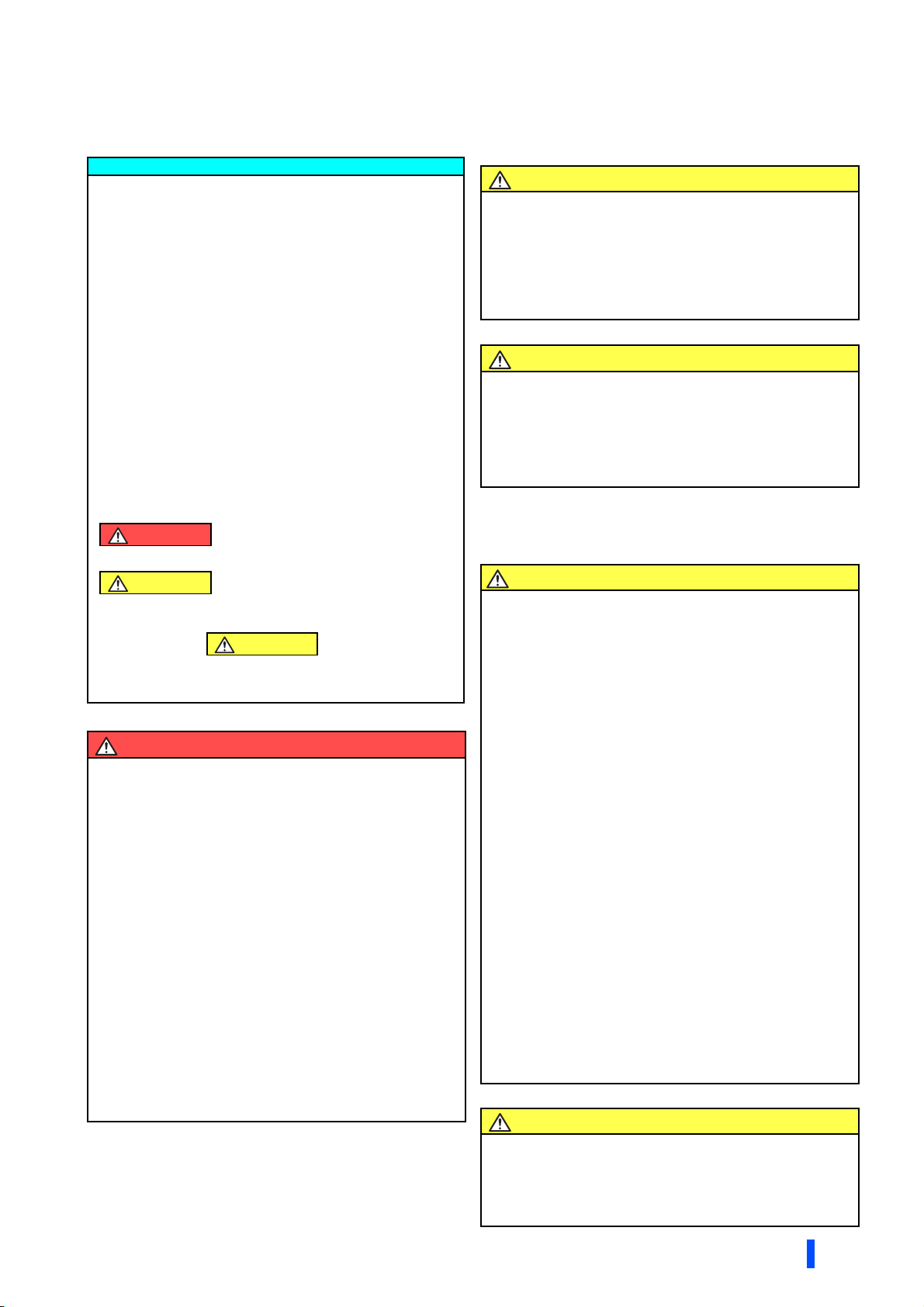
Common bus regeneration mode
Enables continuous regenerative operation at 100% torque. This mode
supports continuous regenerative operations including line operation.
When the converter is connected to multiple inverters, regeneration
energy from an inverter is used for the other inverters. (The FR-XC series
converter can be used as a common converter.) Excessive energy is
returned to the power supply, saving on the energy consumption.
Use the FR-XC series converter in combination with the FR-XCL,
dedicated stand-alone reactor (option).
FR-XCLPower supply
FR-XC
MotorInverter
M
MotorInverter
M
NOTE
• Note that the applicable inverter capacity and current are different if using the FR-XC-(H)18.5K-PWM or FR-XC-(H)22K-PWM
converter with its harmonic suppression function disabled. (Refer to page 156.)
Power regeneration mode
For power driving, the converter section of inverter unit supplies power, and
for regenerative driving, the FR-XC series converter returns power to the
power supply. (The FR-XC series converter cannot be used as a common
converter.)
Since the capacity of power regeneration converter is selectable according to
the regenerative power, the compact and inexpensive power regeneration
converter is applicable when the regenerative power is smaller than the
inverter capacity.
Use the FR-XC series converter in combination with the FR-XCL, dedicated
stand-alone reactor (option).
NOTE
• When installing the converter in a common bus system, do not use the converter in the power regeneration mode.
AC reactor
(FR-HAL)
FR-XCL
Inverter
FR-XC
MotorPower supply
M
8
OUTLINE
Pre-operation instructions
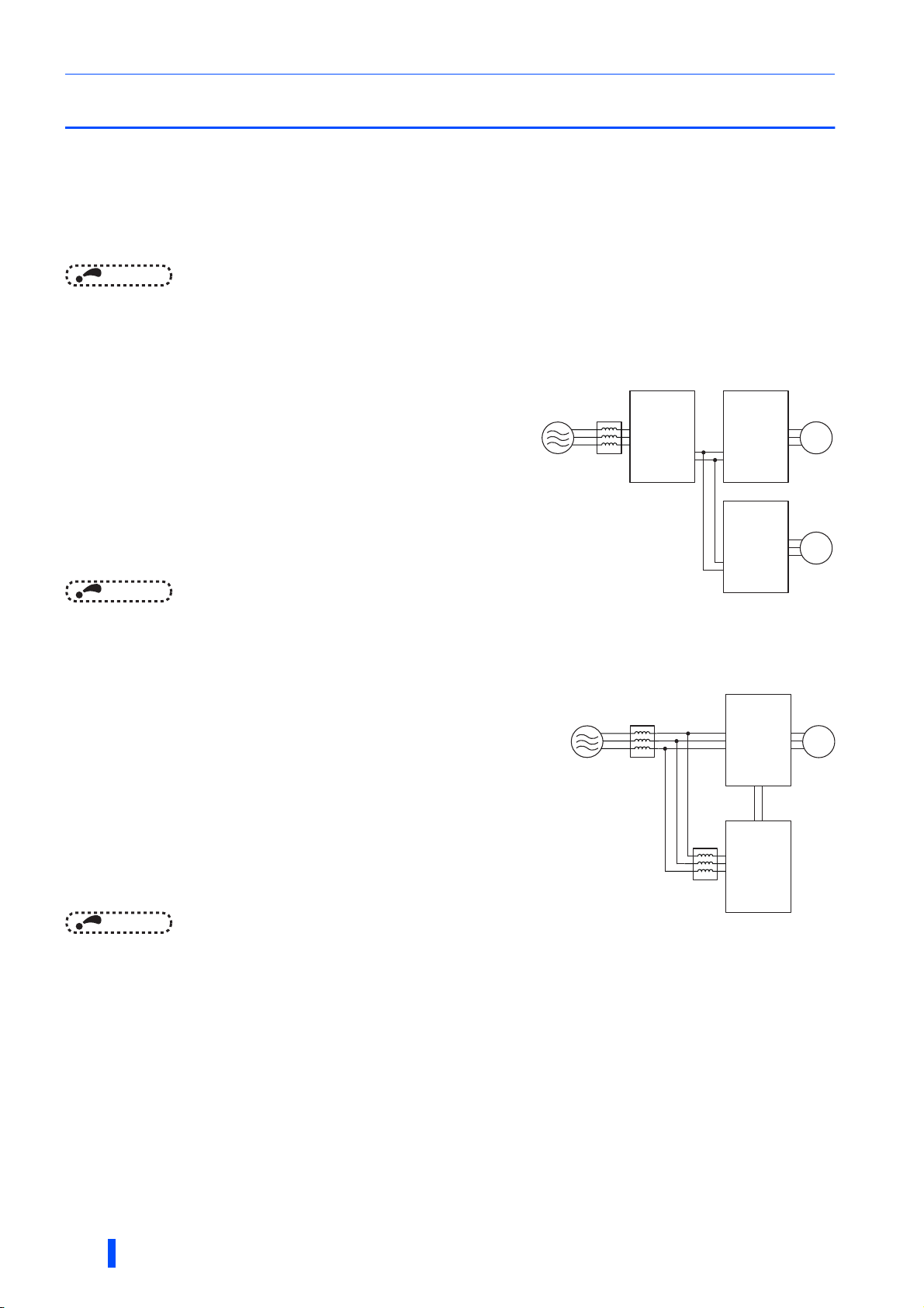
Harmonic suppression
(FR-XC-(H)22K or higher, FR-XC-(H)18.5K-PWM or higher)
The inverter unit has a converter section (rectifier circuit) and generates
power supply harmonics, which may affect the power generator, power
factor correction capacitor, etc. Power supply harmonics are different from
noise and leakage currents in source, frequency band and transmission
path. Power supply harmonics may be suppressed by using the FR-XC
series converter with its harmonic suppression function enabled, allowing
the compliance with the harmonic suppression guidelines issued by the
former Japanese Ministry of International Trade and Industry (currently the
Ministry of Economy, Trade and Industry). The FR-XC series converter with
its harmonic suppression function enabled is classified as the self-excitation
three-phase bridge circuit, and achieves K5 (the conversion factor) = 0. (It is assumed that the FR-XC series converter
generates no harmonics.)
Use the FR-XC series converter in combination with the FR-XCB, dedicated box-type reactor (option).
To enable the harmonic suppression function of the FR-XC-(H)22K or higher, switch to the common bus regeneration mode
and set Pr.416 = "1".
The harmonic suppression function is pre-enabled in the FR-XC-(H)[]K-PWM.
Power supply
FR-XCB
FR-XC
MotorInverter
M
MotorInverter
M
NOTE
• The harmonic suppression function is not available in the power regeneration mode.
• FR-XC-(H)15K or lower does not have the harmonic suppression function.
• Note that the applicable inverter capacity and motor current are different depending on the harmonic suppression function
condition of the FR-XC-(H)22K or FR-XC-(H)30K converter. (Refer to page 156.)
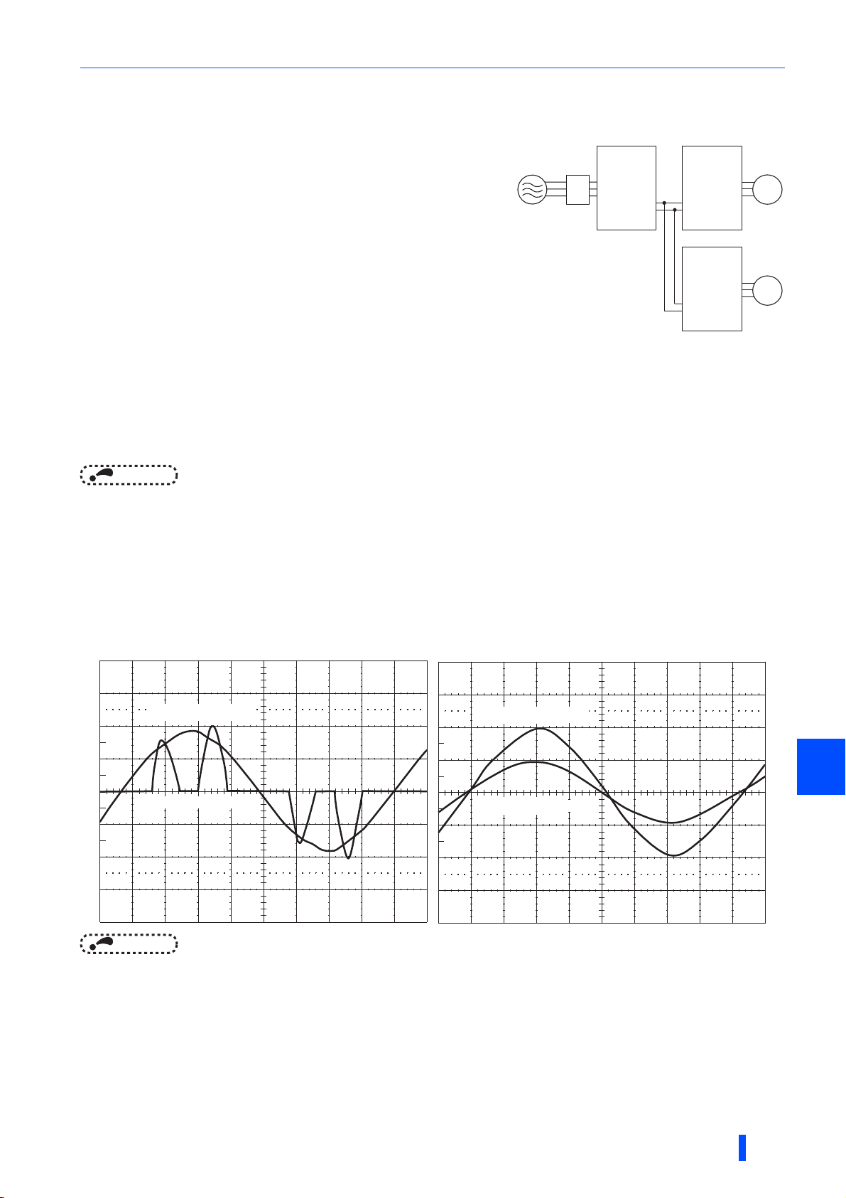
• Power supply harmonic suppression effect
Example of the FR-XC-18.5K-PWM
Condition: Load = 100%
Power factor = 0.99 or more
[Harmonic suppression disabled]
Input phase voltage
Input phase current
[Harmonic suppression enabled]
Input phase voltage
1
Input phase current
NOTE
• It does not mean that harmonic components completely disappear.
• When the load is light, harmonic suppression effect declines.
• When the power supply voltage is unstable, power harmonics flow in, making the harmonic current increase.
Temperature derating selection
By limiting the surrounding air temperature of the multifunction regeneration converter up to 40°C (the surrounding air
temperature of 40°C rating), rated current and applicable current can be increased. (Refer to page 40.)
OUTLINE
9

Pre-operation instructions
Switch Function
1
ON Common bus regeneration mode
OFF Power regeneration mode
2 For manufacturer setting. (Do not change from ON)
3
ON Surrounding air temperature of 50°C rating
OFF Surrounding air temperature of 40°C rating
4 For manufacturer setting. (Do not change from ON)
1.1.2 Function selection switch assembly (SW2)
The function can be changed by the function selection switches.
NOTE
• The changed switch setting is applied at the next power-ON or converter reset.
• If the switch 1 setting (the connection mode setting) does not match the actual wiring of the main circuit terminals, the
connection mode fault "E.T" occurs.
• By checking the parameter prevents unintended operation of multifunction regeneration converter caused by incorrect setting
of switch. (Refer to page 94.)
•Use Pr.416 Control method selection to enable or disable the harmonic suppression function. (Refer to page 40.)
1.1.3 Product checking and parts identification
Unpack the product and check the rating plate and the capacity plate of the multifunction regeneration converter to ensure
that the model and the rated output agree with the order and the product is intact.
Multifunction regeneration converter model
FR-XC- - 60K
Symbol
None
H 400 V class
Rating plate
Multifunction regeneration
converter model
7.5
Voltage class
200 V class
Capacity plate
Multifunction regeneration
converter model
Input rating
Output rating
SERIAL
Country of origin
PWMH
Converter capacity
Capacity (kW)
SERIAL
‵⁁‿‿⁁⁀‟‿⁁‶‷
∗
⁄‷⁀‹‷⁀‟‿⁁‶‷
FR-XC-22K
ᵡᵭᵬᵴᵣᵰᵲᵣᵰ
FR-XC-22K
›⁅
Symbol Circuit board coating
None Without
60 With
06 With
0$'(,1
Plated conductor
Without
Without
With
Symbol
None
PWM Harmonic suppression enabled
∗1 when Pr.416 = "9999"
Functional specification∗1
Harmonic suppression disabled
The rating for "HS" (Harmonic suppression) is shown on the rating plate of the FR-XC-(H)22K
∗
to 55K and FR-XC-(H)18.5K-PWM to 55K-PWM.
Dedicated stand-alone reactor (option) model
FR-XCL- K
Symbol
None
H 400 V class
10
H
Voltage class
200 V class
OUTLINE
Reactor capacity
Capacity (kW)
Dedicated box-type reactor (option) model
FR-XCB- K-
H
Voltage class
200 V class
H 400 V class
Symbol Circuit board coating
None Without
60 With
Reactor capacity
Capacity (kW)
None
Symbol
How to read the SERIAL number
Pre-operation instructions
Ratingplateexample
Symbol Year Month Control number
SERIAL
The SERIAL consists of one symbol, two characters indicating the
production year and month, and six characters indicating the control number.
The last digit of the production year is indicated as the Year, and the Month is
indicated by 1 to 9, X (October), Y (November), or Z (December).
Accessory
• Earthing (grounding) cable (1)
For connection with a communication option. (Refer to page 71.)
• Communication option LED label (1)
For checking the LED indications on the communication option. (Refer to page 71.)
1.1.4 Harmonic suppression guidelines in Japan
Harmonic currents flow from the inverter to a power receiving point via a power transformer. The Harmonic Suppression
Guidelines was established to protect other consumers from these outgoing harmonic currents.
All capacity and all models of general-purpose inverter used by specific consumers are now covered by "the Harmonic
Suppression Guidelines for Consumers Who Receive High Voltage or Special High Voltage" (hereinafter referred to as
"the Specific Consumer Guidelines").
"Specific Consumer Guidelines"
This guideline sets forth the maximum harmonic currents outgoing from a high-voltage or especially high-voltage receiving
consumer who will install, add or renew harmonic generating equipment. If any of the maximum values is exceeded, this
guideline requires that consumer to take certain suppression measures.
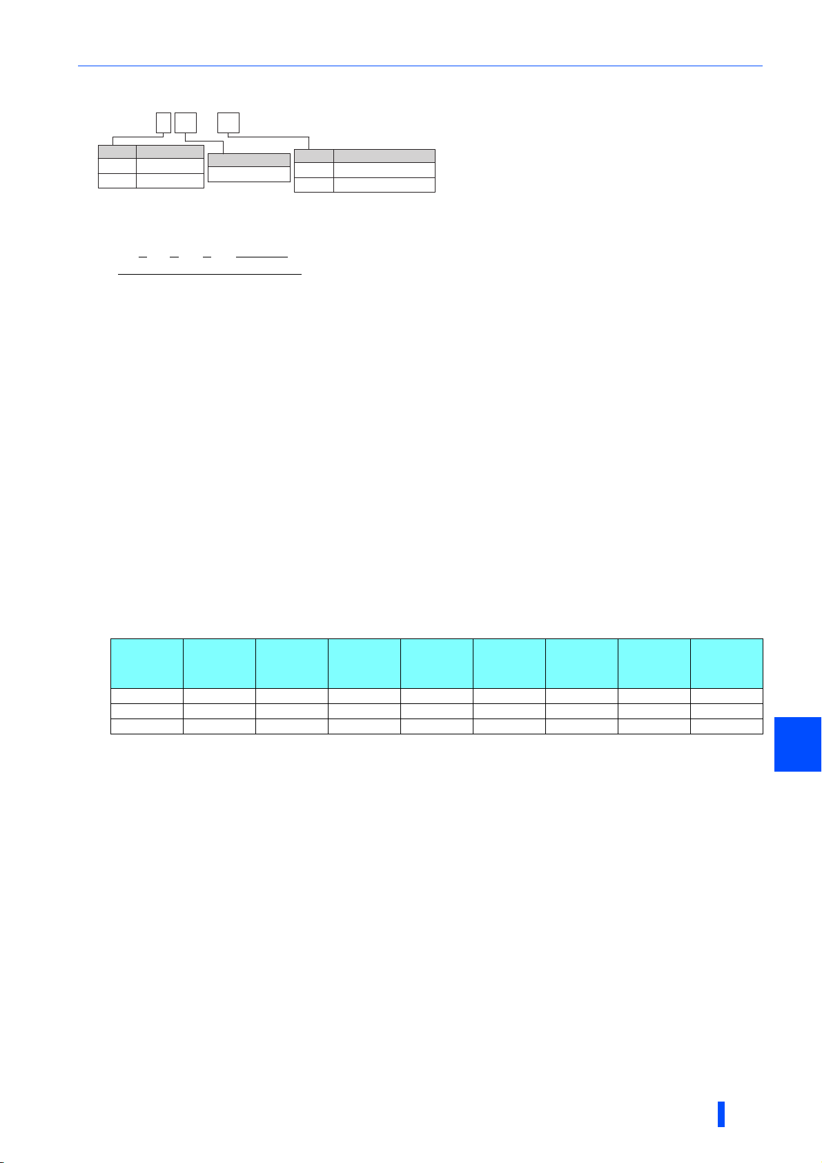
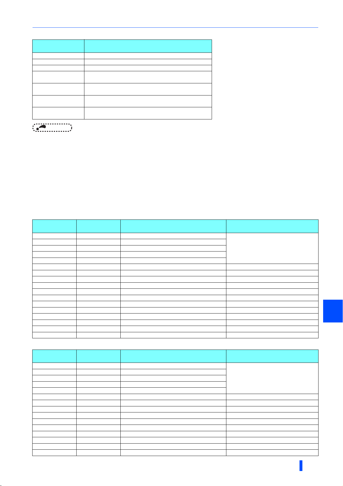
• Maximum values of outgoing harmonic currents per 1 kW contract power
Received
power
voltage
6.6 kV 3.5 2.5 1.6 1.3 1.0 0.9 0.76 0.70
22 kV 1.8 1.3 0.82 0.69 0.53 0.47 0.39 0.36
33 kV 1.2 0.86 0.55 0.46 0.35 0.32 0.26 0.24
5th 7th 11th 13th 17th 19th 23rd Over 23rd
1
OUTLINE
11
Pre-operation instructions
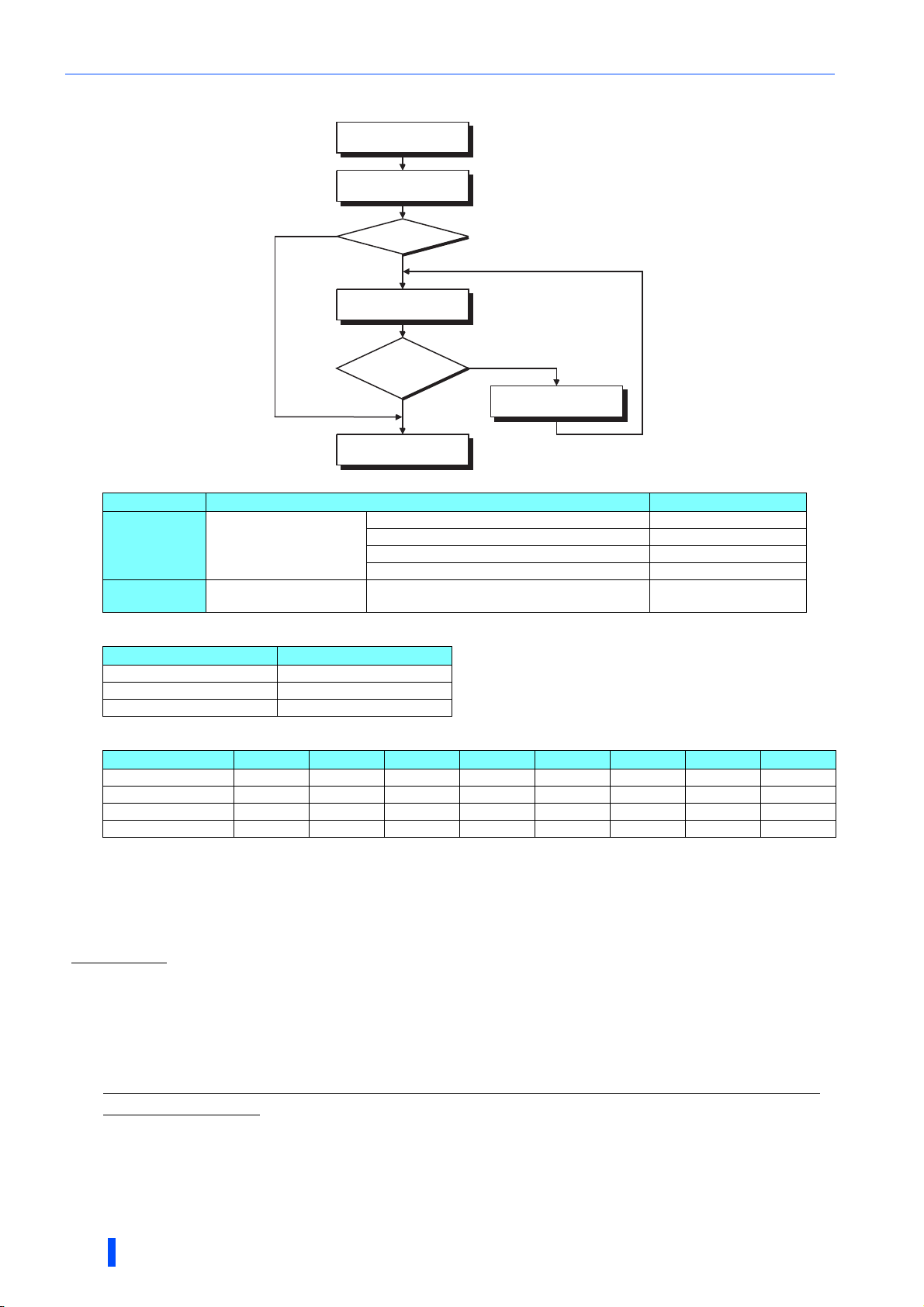
Application of the specific consumer guidelines
Install, add or renew
equipment
Calculation of equivalent
Equal to or less
than reference
capacity
capacity total
Equivalent
capacity total
Above reference
capacity
Calculation of outgoing
harmonic current
Not more than
harmonic current upper
limit?
Equal to or less
than upper limit
Harmonic suppression
measures unnecessary
More than upper limit
Harmonic suppression
measures necessary
• Conversion factor
Classification Circuit type Conversion factor Ki
Without reactor K31 = 3.4
3
5
Three-phase bridge
(capacitor smoothing)
Self-excitation three-phase
bridge
With reactor (AC side) K32 = 1.8
With reactor (DC side) K33 = 1.8
With reactors (AC, DC sides) K34 = 1.4
When a multifunction regeneration converter with
harmonic suppression enabled is used
K5 = 0
• Equivalent capacity limit
Received power voltage Reference capacity
6.6 kV 50 kVA
22/33 kV 300 kVA
66 kV or more 2000 kVA
• Harmonic contents (values of the fundamental current is 100%)
Reactor 5th 7th 11th 13th 17th 19th 23rd 25th
Not used 65 41 8.5 7.7 4.3 3.1 2.6 1.8
Used (AC side) 38 14.5 7.4 3.4 3.2 1.9 1.7 1.3
Used (DC side) 30 13 8.4 5.0 4.7 3.2 3.0 2.2
Used (AC, DC sides) 28 9.1 7.2 4.1 3.2 2.4 1.6 1.4
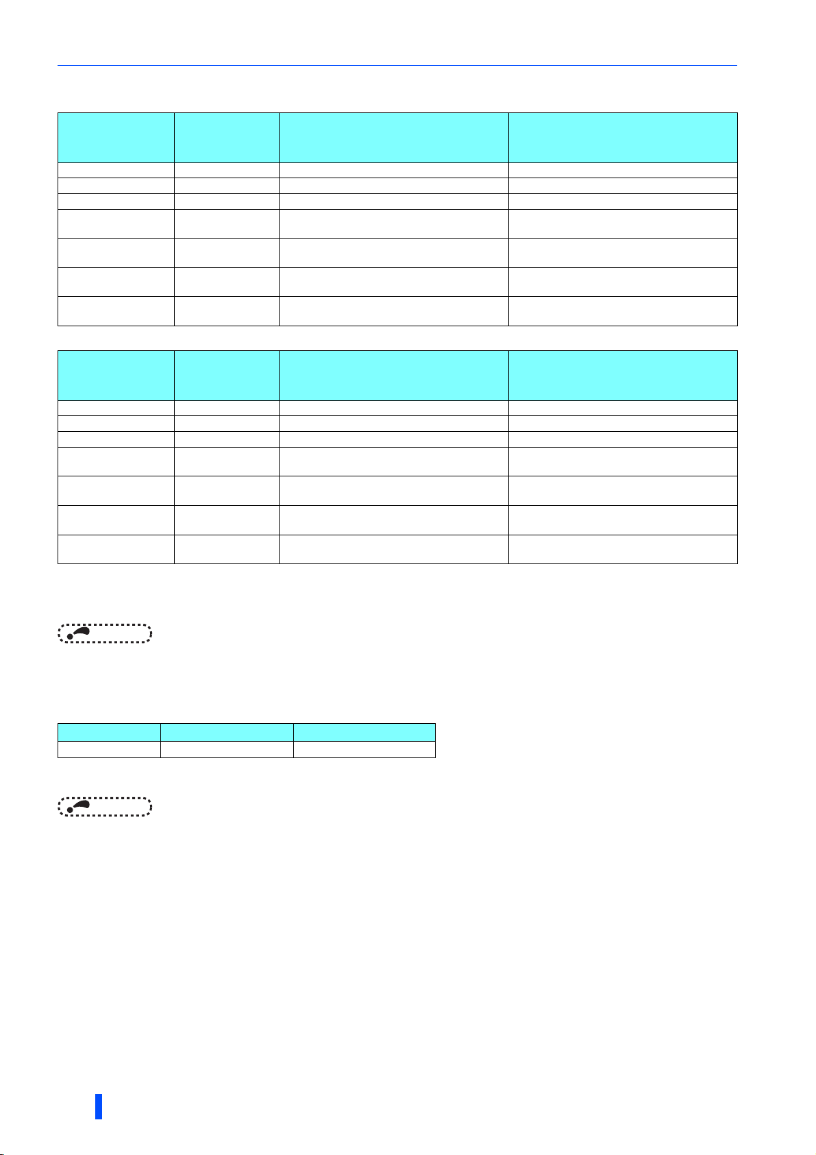
• Calculation of equivalent capacity P0 of harmonic generating equipment
"Equivalent capacity" is the capacity of a 6-pulse converter converted from the capacity of consumer's harmonic
generating equipment and is calculated by the following equation. If the sum of equivalent capacities is higher than the
limit (refer to page 12), harmonics must be calculated by the equation in next subheading.
P0 = Σ (Ki × Pi) [kVA]
Ki: Conversion factor (Refer to page 12.)
Pi: Rated capacity of harmonic generating equipment
i: Number indicating the conversion circuit type
∗1 [kVA]
∗1 Rated capacity: Determined by the capacity of the
applied motor and found in the following table. The
rated capacity used here is used to calculate the
generated harmonic amount and is different from
the power supply capacity required for actual
inverter drive.
• Calculation of outgoing harmonic currents
Outgoing harmonic currents = fundamental wave current (value converted from received power voltage) × operation
ratio × harmonic contents
• Operation ratio: actual load factor × operation time ratio during 30 minutes
• Harmonic contents: Refer to the list of the harmonic contents.
12
OUTLINE

• Rated capacities and outgoing harmonic currents of inverter-driven motors
Pre-operation instructions
Applicable
motor
(kW)
Fundamental
wave current
(A)
200 V 400 V 5th 7th 11th 13th 17th 19th 23rd 25th
Fundamental
wave
current
converted
from 6.6 kV
Rated
capacity
(kVA)
Outgoing harmonic current converted from 6.6 kV (mA)
(No reactor, 100% operation ratio)
(mA)
0.4 1.61 0.81 49 0.57 31.85 20.09 4.165 3.773 2.107 1.519 1.274 0.882
0.75 2.74 1.37 83 0.97 53.95 34.03 7.055 6.391 3.569 2.573 2.158 1.494
1.5 5.50 2.75 167 1.95 108.6 68.47 14.20 12.86 7.181 5.177 4.342 3.006
2.2 7.93 3.96 240 2.81 156.0 98.40 20.40 18.48 10.32 7.440 6.240 4.320
3.7 13.0 6.50 394 4.61 257.1 161.5 33.49 30.34 16.94 12.21 10.24 7.092
5.5 19.1 9.55 579 6.77 376.1 237.4 49.22 44.58 24.90 17.95 15.05 10.42
7.5 25.6 12.8 776 9.07 504.4 318.2 65.96 59.75 33.37 24.06 20.18 13.97
11 36.9 18.5 1121 13.1 728.7 459.6 95.29 86.32 48.20 34.75 29.15 20.18
15 49.8 24.9 1509 17.6 980.9 618.7 128.3 116.2 64.89 46.78 39.24 27.16
18.5 61.4 30.7 1860 21.8 1209 762.6 158.1 143.2 79.98 57.66 48.36 33.48
22 73.1 36.6 2220 25.9 1443 910.2 188.7 170.9 95.46 68.82 57.72 39.96
30 98.0 49.0 2970 34.7 1931 1218 252.5 228.7 127.7 92.07 77.22 53.46
37 121 60.4 3660 42.8 2379 1501 311.1 281.8 157.4 113.5 95.16 65.88
45 147 73.5 4450 52.1 2893 1825 378.3 342.7 191.4 138.0 115.7 80.10
55 180 89.9 5450 63.7 3543 2235 463.3 419.7 234.4 169.0 141.7 98.10
• Determining if a countermeasure is required
A countermeasure for harmonics is required if the following condition is satisfied: outgoing harmonic currents >
maximum value per 1 kW contract power × contract power.
• Harmonic suppression techniques
No.
Reactor
1
(FR-HAL or FR-HEL)
Multifunction
regeneration
2
converter
(FR-XC series)
Power factor
3
improving capacitor
Transformer multi-
4
phase operation
Passive filter
5
(AC filter)
6 Active filter
Item Description
Install an AC reactor (FR-HAL) on the AC side of the inverter or a DC reactor (FR-HEL) on its DC side,
or install both to suppress outgoing harmonic currents.
The multifunction regeneration converter with harmonic suppression enabled switches the converter
section ON/OFF to reshape an input current waveform into a sine wave, greatly suppressing
harmonics.
Use the FR-XC series converter with the FR-XCB box-type reactor.
When used with a reactor connected in series, the power factor improving correction capacitor can
absorb harmonic currents.
Use two transformers and establish connections with a phase angle difference of 30° (the wye to delta
connection or the delta to delta connection) to provide an effect corresponding to 12 pulses, reducing
low-degree harmonic currents.
A capacitor and a reactor are used together to reduce impedances at specific frequencies. Harmonic
currents are expected to be absorbed greatly by using this technique.
This filter detects the current in a circuit generating a harmonic current and generates a harmonic
current equivalent to a difference between that current and a fundamental wave current to suppress
the harmonic current at the detection point. Harmonic currents are expected to be absorbed greatly by
using this technique.
1
OUTLINE
13
Component names
(d)
(f)
(e)
(h)
(a)
(c)
(l)
(i)
(i)
(i)
(b)
(m)
(k)
(g)
(j)
(i)
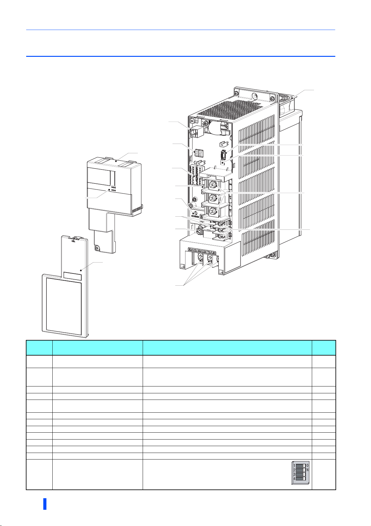
1.2 Component names
Component names are shown below.
30K converters or lower
Symbol Name Description
(a) Control circuit terminal block cover
(b)
(c)
(d) PU connector
(e)
(f) Control circuit terminal block Connect cables for the control circuit. 50
(g)
(h) Charge lamp Stays ON while the power is supplied to the main circuit. 72
(i) Main circuit terminal block Connect cables for the main circuit. 41
(j) Connector for manufacturer setting
(k) Cooling fan
(l) Connector for communication option Connect cables for the communication option (FR-A8NC). 71
(m)
Communication operation status
inspection port
(for the FR-A8NC)
Main control circuit terminal block cover
Operation status 7-segment LED
display
Control logic switchover jumper connector
Function selection switch assembly
(SW2)
Remove it for installing a communication option, wiring the control circuit
terminals, or changing the SW2 switches.
Check the state (ON/blinking) of the communication operation status
indicators on the communication option (FR-A8NC) when the option is
installed.
Remove it for wiring. 26
Connector for parameter units. Also used for the RS-485 communication.
Check the display indication or LED state (ON/blinking) for the operation
status of the converter.
Change the control logic of input signals as necessary. 51
Do not remove the cap from the connector.
Cools the multifunction regeneration converter.
1: Connection mode (common bus regeneration mode
/ power regeneration mode) selection
2: For manufacturer setting
3: Temperature derating selection
4: For manufacturer setting
to page
26
⎯
103
72
⎯
149
10
Refer
14
OUTLINE
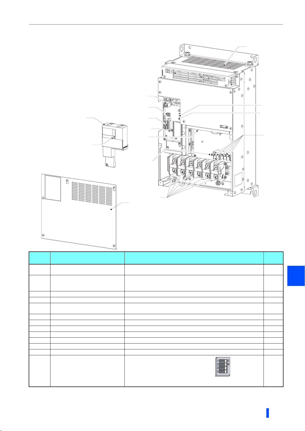
37K converters or higher
Component names
(k)
(d)
(a)
(b)
(c)
(e)
(f)
(h)
(l)
(m)
(g)
(j)
(i)
(j)
Symbol Name Description
(a) Control circuit terminal block cover
Communication operation status
(b)
(c)
(d) PU connector
(e)
(f) Control circuit terminal block Connect cables for the control circuit. 50
(g)
(h) Charge lamp Stays ON while the power is supplied to the main circuit. 72
(i) Main circuit terminal block Connect cables for the main circuit. 41
(j) Connector for manufacturer setting
(k) Cooling fan
(l) Connector for communication option Connect cables for the communication option (FR-A8NC). 71
(m)
inspection port
(for the FR-A8NC)
Main control circuit terminal block cover
Operation status 7-segment LED
display
Control logic switchover jumper connector
Function selection switch assembly
(SW2)
Remove it for installing a communication option, wiring the control circuit
terminals, or changing the SW2 switches.
Check the state (ON/blinking) of the communication operation status
indicators on the communication option (FR-A8NC) when the option is
installed.
Remove it for wiring. 26
Connector for parameter units. Also used for the RS-485 communication.
Check the display indication or LED state (ON/blinking) for the operation
status of the converter.
Change the control logic of input signals as necessary. 51
Do not remove the cap from the connector.
Cools the multifunction regeneration converter.
1: Connection mode (common bus
regeneration mode / power regeneration
mode) selection
2: For manufacturer setting
3: Temperature derating selection
4: For manufacturer setting
to page
26
⎯
103
72
⎯
149
10
Refer
1
OUTLINE
15
FR-XC series converter and peripheral devices
(Refer to page 60.)
(Refer to page 57.)
(Refer to page 51.)
(Refer to page 21.)
(Refer to page 19.)
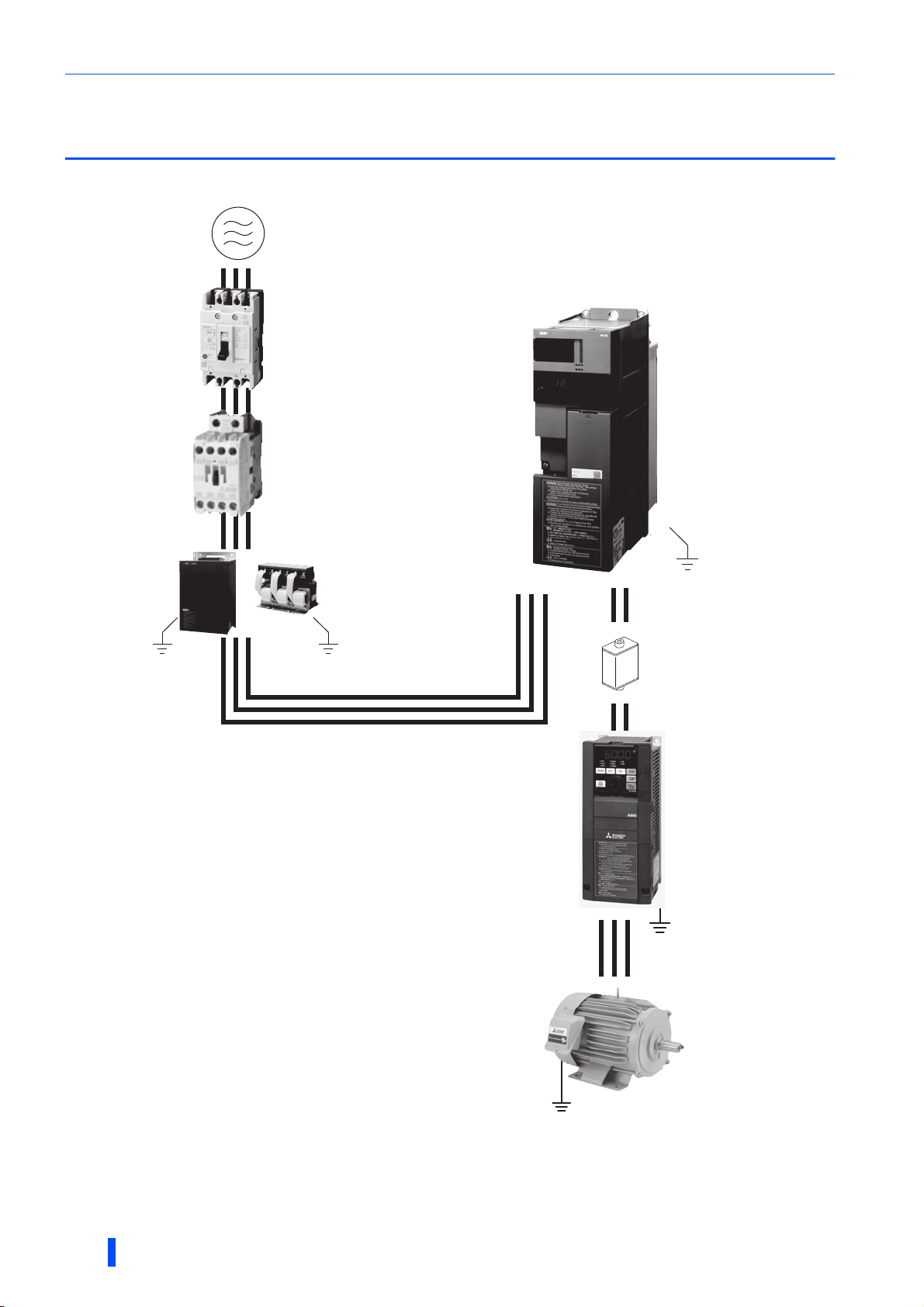
1.3 FR-XC series converter and peripheral
devices
<Example for the common bus regeneration mode>
Three-phase AC power supply
Use power supply within the
permissible specifications of the
converter.
Molded case circuit breaker (MCCB) or
earth leakage circuit breaker (ELB) and fuse
The breaker must be selected carefully since
an inrush current flows in the converter at
power ON.
FR-XC series converter
Install and wire correctly.
Magnetic contactor (MC)
Install the MC to ensure safety.
Do not use this MC to start and stop the
converter and the inverter. Doing so will
shorten the life of the inverter and the
converter.
Do not install a molded case
circuit breaker (MCCB) on the
main circuit cables between the
inverter and the converter
(terminals P to P and terminals N
to N).
Earth (ground)
Dedicated box-type reactor
FR-XCB
(used when harmonic
suppression enabled)
Confirm that the capacity of the
FR-XCB reactor is appropriate
for the capacity of the converter.
Dedicated stand-alone reactor
FR-XCL
(used when harmonic
suppression disabled)
Confirm that the capacity of the
FR-XCL reactor is appropriate for
the capacity of the converter.
Earth (ground)
Devices on the inverter's output side
Do not install a power factor correction capacitor or surge
suppressor or capacitor type filter on the inverter's output
side.
When installing a molded case circuit breaker (MCCB) on
the inverter's output side, contact the manufacturer of
MCCB for MCCB selection.
Earth (ground)
Always earth (ground) the converter, the dedicated reactor
FR-XCL or FR-XCB, the inverter, and the motor.
R2 S2PNT2
Fuse
Installation of a fuse is
recommended for safety. Select a
fuse according to the connected
motor capacity.
Inverter
Select an inverter according to
the capacity of the converter.
The control logic (sink
logic/source logic) of the
converter and the inverter must
be matched.
Earth (ground)
Motor
Earth (ground)
16
Earth (ground)
OUTLINE

Precautions for selecting peripheral devices
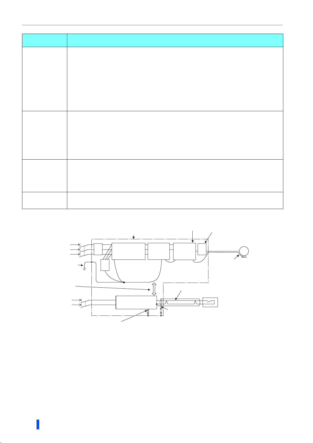
Noise propagated
through power supply
cable
…Path (c)
…Path (b)
…Path (a)
Noise directly radiated
from converter
…Path (d), (e)
Air propagated
noise
…Path (f)
Electrical path
propagated noise
…Path (h)
…Path (g)
Multifunction regeneration
converter generated
electromagnetic noise
Electromagnetic
induction noise
Electrostatic
induction noise
Noise radiated from
power supply cable
Noise radiated from
motor connection cable
Noise from earthing
(grounding) cable
due to leakage current
1.4 Precautions for selecting peripheral devices
1.4.1 Techniques and measures for electromagnetic
compatibility (EMC)
Some electromagnetic noises enter the converter to cause the converter malfunction, and others are radiated by the
converter to cause the peripheral devices to malfunction. (The former is called electromagnetic susceptibility (EMS) problem,
the latter is called electromagnetic interference (EMI) problem, and both is called electromagnetic compatibility (EMC)
problem.) Though the FR-XC series converter is designed to be immune to noises, it requires the following basic measures
and EMS measures as it handles low-level signals. Pay attention to the electromagnetic noises that could be generated by the
FR-XC series converter. If these noises cause peripheral devices to malfunction, EMI measures should be taken to suppress
noises. These techniques differ slightly depending on EMI paths.
Basic measures
• Do not run the power cables (I/O cables) and signal cables of the converter in parallel with each other and do not bundle
them.
• Use shielded twisted pair cables for the detector connecting and control signal cables and connect the sheathes of the
shielded cables to terminal SD.
• Ground (earth) the reactor, the converter, the inverter, etc. at one point. (Refer to page 66.)
EMS measures to reduce electromagnetic noises that enter the
When devices that generate many electromagnetic noises (which use magnetic contactors, electromagnetic brakes, many
relays, for example) are installed near the converter and the converter may malfunction due to electromagnetic noises, the
following countermeasures must be taken.
• Provide surge suppressors for devices that generate many electromagnetic noises to suppress electromagnetic noises.
• Install data line filters to signal cables.
• Ground (Earth) the shields of the detector connection and control signal cables with cable clamp metal.
Converter-generated noises are largely classified into those radiated by the converter itself and by the cables (I/O)
connected to its main circuit, those electromagnetically and electrostatically induced to the signal cables of the peripheral
devices close to the power cable connected to the converter main circuit, and those transmitted through the power cables.
converter and cause it to malfunction
EMI measures to reduce electromagnetic noises that are radiated by the
converter to cause the peripheral devices to malfunction
(g)
Instrument Receiver
(b)
(a)
Motor
(e)
Dedicated reactor
or
box-type reactor
Multifunction
regeneration
converter
(c)
Inverter
M
(g)
(d)
(f)
(c)
OUTLINE
Sensor
power supply
(a)
Sensor
Telephone
(h)
1
17
Precautions for selecting peripheral devices
refer to page 66.
Noise
propagation path
(a), (b), (c)
(d), (e), (f)
(g)
(h)
Measure
When devices that handle low-level signals and are liable to malfunction due to electromagnetic noises, e.g.
instruments, receivers and sensors, are contained in the enclosure that contains the converter or when their signal
cables are run near the converter, the devices may malfunction due to by air-propagated electromagnetic noises.
The following measures must be taken:
• Install the easily affected devices as far away from the converter and the inverter as possible.
• Place the easily affected signal cables as far away from the converter and the inverter as possible.
• Do not run signal cables and power cables (converter I/O cables) in parallel with each other and do not bundle
them.
• Install the FR-BLF line noise filter or the FR-BIF radio noise filter on the input side of the converter and install the
FR-BLF on the output side of the inverter to suppress the radiated noise from the cables.
• Use shielded cables as signal cables and power cables, and run them in individual metal conduits, to produce
further effects.
When the signal cables are run in parallel with or bundled with the power cables, magnetic and static induction
noises may be propagated to the signal cables to cause malfunction of the devices. The following measures must
be taken:
• Install the easily affected devices as far away from the converter and the inverter as possible.
• Place the easily affected signal cables as far away from the converter and the inverter as possible.
• Do not run signal cables and power cables (converter I/O cables) in parallel with each other and do not bundle
them.
• Use shielded cables as signal cables and power cables, and run them in individual metal conduits, to produce
further effects.
When the power supplies of the peripheral devices are connected to the power supply of the converter in the same
line, converter-generated noises may flow back through the power supply cables to cause malfunction of the
devices. The following measures must be taken:
• Install the FR-BIF radio noise filter on the input side power cable of the converter.
• Install the FR-BLF line noise filters on the input side power cable of the converter and on the output side power
cable of the inverter.
When a closed loop circuit is formed by connecting the peripheral devices wiring to the converter, leakage currents
may flow through the earthing (grounding) cable of the converter to cause the devices to malfunction. In that case,
disconnecting the earthing (grounding) cables from the devices may stop the malfunction of the devices.
EMI measure example
Power source
for main circuit
For earthing (grounding)
of the converter,
It is preferred that the
inverter, the converter, and
power cables are separated
from sensor circuit by 30 cm
or more (at least 10 cm).
Power source
for control circuit
Decrease the carrier frequency.
Multifunction
regeneration
converter
Inverter
FRBLF
Enclosure
Dedicated reactor
or
box-type reactor
FRBIF
Use a twisted pair shielded cable.
Power supply
for sensor
Do not earth (ground) shield but connect it to signal common cable.
Do not connect earthing (grounding) cables of the sensor directly to the enclosure.
Do not use control cables for earthing (grounding).
Install the filter (FR-BLF/FR-BSF01)
on the inverter output side.
FRBLF
Use a 4-core cable as motor power cable
and use one wire as earth (ground) cable.
Sensor
Motor
M
18
OUTLINE
Precautions for selecting peripheral devices
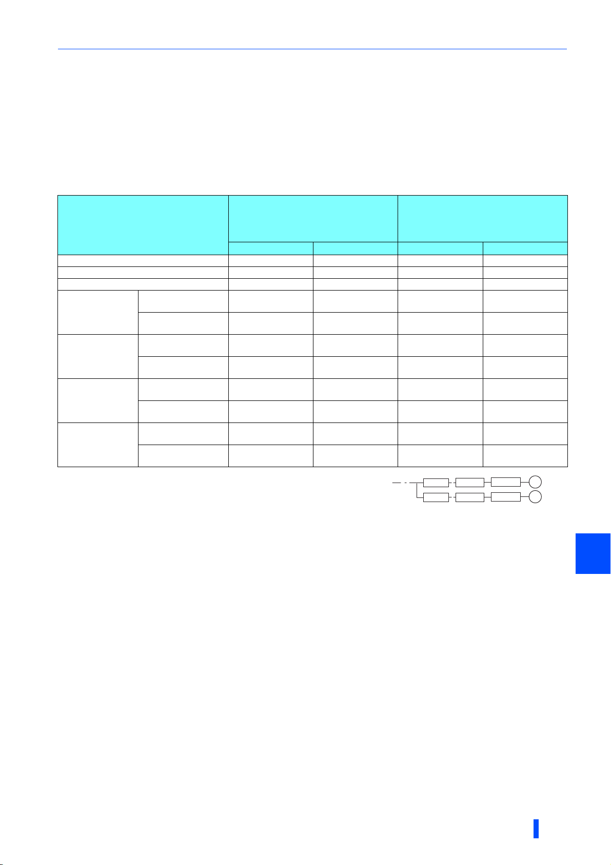
1.4.2 Peripheral device list
Circuit breaker and magnetic contactor
Check the model of the purchased multifunction regeneration converter. Appropriate peripheral devices must be selected
according to the capacity.
Common bus regeneration mode
For the converter in common bus regeneration mode, refer to the following table to prepare appropriate peripheral
devices.
• 200 V class
Molded case circuit breaker
(MCCB)∗1/
FR-XC series converter model
earth leakage circuit breaker (ELB)
(NF, NV type)
50°C rating 40°C rating 50°C rating 40°C rating
FR-XC-7.5K 60 A 60 A S-T35 S-T35
FR-XC-11K 75 A 75 A S-T35 S-T35
FR-XC-15K 125 A 125 A S-T50 S-T50
FR-XC-22K
FR-XC-18.5K-PWM
FR-XC-30K
FR-XC-22K-PWM
FR-XC-37K
FR-XC-37K-PWM
FR-XC-55K
FR-XC-55K-PWM
∗1 Select an MCCB according to the power supply capacity.
Install one MCCB per converter.
(For the use in the United States or Canada, refer to page 179.)
∗2 The magnetic contactor is selected based on the AC-1 class. The electrical durability of
magnetic contactor is 100,000 times. When the magnetic contactor is used for emergency stops during motor driving, the electrical durability is
25 times.
If using an MC for emergency stop during motor driving or using it on the motor side during commercial power supply operation, select an MC
with the class AC-3 rated current for the rated motor current.
Harmonic suppression
disabled
Harmonic suppression
enabled
Harmonic suppression
disabled
Harmonic suppression
enabled
Harmonic suppression
disabled
Harmonic suppression
enabled
Harmonic suppression
disabled
Harmonic suppression
enabled
175 A 175 A S-T65 S-T80
125 A 125 A S-T50 S-T50
225 A 225 A S-T100 S-T100
125 A 125 A S-T65 S-T65
250 A 250 A S-N150 S-N150
200 A 200 A S-T100 S-N150
400 A 400 A S-N180 S-N180
300 A 300 A S-N180 S-N180
Magnetic contactor (MC)∗2
MCCB
MCCB
FR-XC
FR-XC
Inverter
Inverter
M
M
OUTLINE
1
19
Precautions for selecting peripheral devices
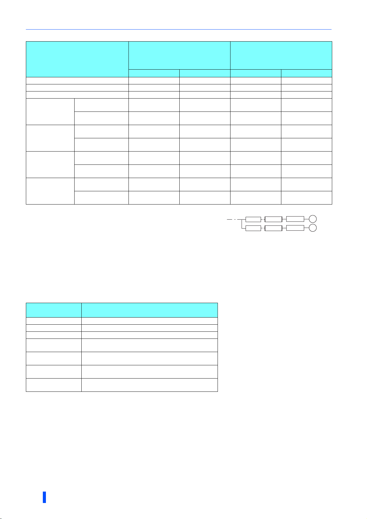
• 400 V class
Molded case circuit breaker
(MCCB)∗1/
FR-XC series converter model
earth leakage circuit breaker (ELB)
(NF, NV type)
50°C rating 40°C rating 50°C rating 40°C rating
FR-XC-H7.5K 30 A 30 A S-T21 S-T21
FR-XC-H11K 50 A 50 A S-T21 S-T21
FR-XC-H15K 60 A 60 A S-T35 S-T35
FR-XC-H22K
FR-XC-H18.5KPWM
FR-XC-H30K
FR-XC-H22K-PWM
FR-XC-H37K
FR-XC-H37K-PWM
FR-XC-H55K
FR-XC-H55K-PWM
Harmonic suppression
disabled
Harmonic suppression
enabled
Harmonic suppression
disabled
Harmonic suppression
enabled
Harmonic suppression
disabled
Harmonic suppression
enabled
Harmonic suppression
disabled
Harmonic suppression
enabled
100 A 100 A S-T35 S-T35
60 A 60 A S-T35 S-T35
125 A 125 A S-T50 S-T50
75 A 75 A S-T35 S-T35
150 A 150 A S-T65 S-T65
100 A 100 A S-T50 S-T65
200 A 200 A S-T100 S-T100
150 A 150 A S-T80 S-T80
Magnetic contactor (MC)∗2
∗1 Select an MCCB according to the power supply capacity.
Install one MCCB per converter.
(For the use in the United States or Canada, refer to page 179.)
∗2 The magnetic contactor is selected based on the AC-1 class. The electrical durability of
magnetic contactor is 100,000 times. When the magnetic contactor is used for emergency stops during motor driving, the electrical durability is
25 times.
If using an MC for emergency stop during motor driving or using it on the motor side during commercial power supply operation, select an MC
with the class AC-3 rated current for the rated motor current.
MCCB
MCCB
FR-XC
FR-XC
Inverter
Inverter
Power regeneration mode
To use the converter in power regeneration mode, select a circuit breaker and a magnetic contactor (MC) for the inverter
according to the inverter capacity. For details, refer to the Instruction Manual of each inverter.
Additionally, install a molded case circuit breaker (MCCB) or earth leakage circuit breaker (ELB) with the rating shown in
the following table on the input side of the FR-XCL reactor. For the information of the installation location, refer to page 58.
• 200 V class
FR-XC series
converter model
FR-XC-7.5K 50 A
FR-XC-11K 60 A
FR-XC-15K 75 A
FR-XC-22K
FR-XC-18.5K-PWM
FR-XC-30K
FR-XC-22K-PWM
FR-XC-37K
FR-XC-37K-PWM
FR-XC-55K
FR-XC-55K-PWM
Molded case circuit breaker (MCCB)/
earth leakage circuit breaker (ELB)
125 A
175 A
200 A
250 A
(NF, NV type)
M
M
20
OUTLINE
Precautions for selecting peripheral devices
• 400 V class
FR-XC series
converter model
FR-XC-H7.5K 30 A
FR-XC-H11K 30 A
FR-XC-H15K 40 A
FR-XC-H22K
FR-XC-H18.5K-PWM
FR-XC-H30K
FR-XC-H22K-PWM
FR-XC-H37K
FR-XC-H37K-PWM
FR-XC-H55K
FR-XC-H55K-PWM
Molded case circuit breaker (MCCB)/
earth leakage circuit breaker (ELB) (NF, NV type)
75 A
100 A
125 A
150 A
NOTE
• If any breaker trips, check for the wiring fault (such as short circuit), damage to internal parts of the multifunction regeneration
converter, etc. The cause of the trip must be identified and removed before turning ON the power of the breaker.
Fuse
Installation of a fuse between the multifunction regeneration converter and the inverter is recommended.
When using the converter in the common bus regeneration mode, select a fuse according to the capacity of the connected
motor. When using a motor whose capacity is smaller than the inverter capacity by two ranks or more, select the fuse with the
capacity that is one rank lower than the inverter capacity.
When using the converter in power regeneration mode, select a fuse according to the capacity of the converter.
(Refer to page 60 for wiring between the converter and the inverter.)
Common bus regeneration mode
• 200 V class
Motor capacity
(kW)
0.1 5 6.900 CP GR 10.38 0005 (FR10GR69V5)
0.2 10 6.900 CP GR 10.38 0010 (FR10GR69V10)
0.4 16 6.900 CP GR 10.38 0016 (FR10GR69V16)
0.75 20 6.900 CP GR 10.38 0020 (FR10GR69V20)
1.5 25 6.900 CP GR 10.38 0025 (FR10GR69V25)
2.2 50 6.9 URD 30 TTF 0050 —
3.7 63 6.9 URD 30 TTF 0063 —
5.5 100 6.9 URD 30 TTF 0100 —
7.5 125 6.9 URD 30 TTF 0125 —
11 160 6.9 URD 30 TTF 0160 —
15 200 6.9 URD 30 TTF 0200 —
18.5 250 6.9 URD 30 TTF 0250 —
22 315 6.9 URD 30 TTF 0315 —
30 400 6.9 URD 30 TTF 0400 —
37 500 6.9 URD 30 TTF 0500 —
45 630 6.9 URD 31 TTF 0630 —
55 700 6.9 URD 31 TTF 0700 —
• 400 V class
Motor capacity
(kW)
0.4 12.5 6.900 CP GR 10.38 0012.5 (FR10GR69V12.5)
0.75 16 6.900 CP GR 10.38 0016 (FR10GR69V16)
1.5 16 6.900 CP GR 10.38 0016 (FR10GR69V16)
2.2 20 6.900 CP GR 10.38 0020 (FR10GR69V20)
3.7 30 6.900 CP GR 10.38 0030 (FR10GR69V30)
5.5 50 6.9 URD 30 TTF 0050 —
7.5 50 6.9 URD 30 TTF 0050 —
11 80 6.9 URD 30 TTF 0080 —
15 125 6.9 URD 30 TTF 0125 —
18.5 125 6.9 URD 30 TTF 0125 —
22 160 6.9 URD 30 TTF 0160 —
30 200 6.9 URD 30 TTF 0200 —
37 250 6.9 URD 30 TTF 0250 —
45 315 6.9 URD 30 TTF 0315 —
55 350 6.9 URD 30 TTF 0350 —
Fuse rating (A) Model∗1 Fuse holder (2 poles)
Fuse rating (A) Model∗1 Fuse holder (2 poles)
US102 (without fuse light melting indicator)
or US102I (with fuse light melting indicator)
1
US102 (without fuse light melting indicator)
or US102I (with fuse light melting indicator)
OUTLINE
21
Precautions for selecting peripheral devices
Power regeneration mode
• 200 V class
FR-XC series
converter
capacity (kW)
FR-XC-7.5K 125 6.9 URD 30 TTF 0125 —
FR-XC-11K 160 6.9 URD 30 TTF 0160 —
FR-XC-15K 200 6.9 URD 30 TTF 0200 —
FR-XC-22K
FR-XC-18.5K-PWM
FR-XC-30K
FR-XC-22K-PWM
FR-XC-37K
FR-XC-37K-PWM
FR-XC-55K
FR-XC-55K-PWM
• 400 V class
FR-XC series
converter capacity
(kW)
FR-XC-H7.5K 50 6.9 URD 30 TTF 0050 —
FR-XC-H11K 80 6.9 URD 30 TTF 0080 —
FR-XC-H15K 125 6.9 URD 30 TTF 0125 —
FR-XC-H22K
FR-XC-H18.5K-PWM
FR-XC-H30K
FR-XC-H22K-PWM
FR-XC-H37K
FR-XC-H37K-PWM
FR-XC-H55K
FR-XC-H55K-PWM
Fuse rating (A) Model∗1 Fuse holder (2 poles)
315 6.9 URD 30 TTF 0315 —
400 6.9 URD 30 TTF 0400 —
500 6.9 URD 30 TTF 0500 —
700 6.9 URD 31 TTF 0700 —
Fuse rating (A) Model∗1 Fuse holder (2 poles)
160 6.9 URD 30 TTF 0160 —
200 6.9 URD 30 TTF 0200 —
250 6.9 URD 30 TTF 0250 —
350 6.9 URD 30 TTF 0350 —
∗1 Manufacturer: Mersen Japan KK
Contact: Sun-Wa Technos Corporation
NOTE
• Install fuses across terminals P/+ and P/+, and across terminals N/- and N/- of the multifunction regeneration converter and
the inverter.
[Estimated lifespan of fuses]
Components Estimated lifespan∗1 Replacement method
Fuse 10 years Replace by new one
∗1 Estimated lifespan for when the yearly average surrounding air temperature is 50°C. (without corrosive gas, flammable gas, oil mist, dust and
dirt etc.)
NOTE
• If the fuse melts down, wiring failure such as a short circuit may be the cause. Find out the cause and remove it before
replacing the fuse.
22
OUTLINE
Precautions for selecting peripheral devices
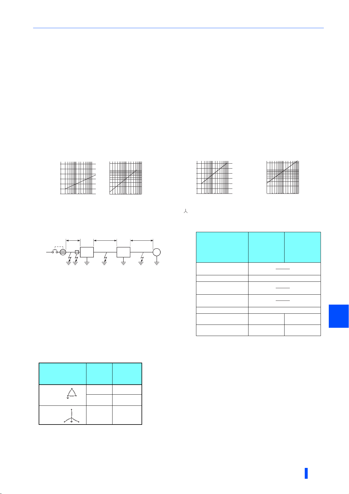
Ig1, lg2, lg3: Leakage currents in wire path during
commercial power supply operation
Ign: Leakage current from noise filters on the input side
of the converter
Igm: Leakage current from the motor during
commercial power supply operation
Selection example (diagram shown on the left) (mA)
Breaker
designed for
harmonic and
surge
suppression
Standard
breaker
Leakage current lg1 (mA)
33 × = 0.17
Leakage current lgn (mA) 0 (without noise filter)
Leakage current lg2 (mA)
33 × = 0.17
Leakage current lg3 (mA)
33 × = 2.31
Leakage current lgm (mA) 0.18
Total leakage current
(mA)
2.83 7.81
Rated sensitivity current
(≥ Ig × 10) (mA)
30 100
1.4.3 Selecting the rated sensitivity current for the
earth leakage circuit breaker
To install the earth leakage circuit breaker on the inverter circuit, select its rated sensitivity current as follows.
• Breaker designed for harmonic and surge suppression
Rated sensitivity current
I∆n ≥ 10 × (Ig1 + Ign + Ig2 + Ig3 + Igm)
• Standard breaker
Rated sensitivity current
I∆n ≥ 10 × {Ig1 + Ign + Ig2 + 3 × (Ig3 + Igm)}
Example of leakage current of
cable path per 1km during the
commercial power supply operation
when the CV cable is routed in
metal conduit
(200 V 60 Hz) (200 V 60 Hz)
120
100
80
60
40
20
[Example]
0
Leakage currents (mA)
2 3.5
8142230386080
5.5
Cable size (mm2)
2
5.5 mm
×5 m
ELB
Noise
filter
FR-XC
converter
Leakage currents (mA)
150
100
5.5 mm2×5 m 5.5 mm2×70 m
lg1 lgn lg2 lg3
Leakage current example of
three-phase induction motor
during the commercial
power supply operation
2. 0
1. 0
0. 7
0. 5
0. 3
0. 2
0. 1
1. 5 3.7
7. 5 152211373055
2. 2
Motor capacity (kW)
Inverter
455.5 18. 5
3φ
IM
200 V 2.2 kW
lgm
Example of leakage current per 1km during
the commercial power supply operation
when the CV cable is routed in metal conduit
(Three-phase three-wire delta
connection 400 V 60 Hz)
120
100
80
60
40
20
0
2 3.5
8142230386080
size (mm2)
100
150
Leakage currents (mA)
For " " connection, the amount of leakage current is appox.1/3 of the above value.
5.5
Cable
Leakage current example of threephase induction motor during the
commercial power supply operation
(Totally-enclosed fan-cooled
type motor 400 V 60 Hz)
2. 0
1. 0
0. 7
0. 5
0. 3
0. 2
0. 1
1. 5 3.7
Leakage currents (mA)
7. 5 152211373055
2. 2
Motor capacity (kW)
455.5 18. 5
5 m
1000 m
5 m
1000 m
70 m
1000 m
• Multifunction regeneration converter leakage current
Input power conditions
: 220 V/60 Hz (200 V class) or 440 V/60 Hz (400 V class), within 3% of power supply unbalance
Voltage
(V)
Leakage
current
Phase
earthing
(grounding)
Earthed-neutral
system
200 2
400 4
400 4
(mA)
OUTLINE
1
23

Precautions for selecting peripheral devices
NOTE
• Install the earth leakage circuit breaker (ELB) on the input side of the converter.
• In the connection earthed-neutral system, the sensitivity current is blunt against a ground fault in the inverter output side.
Earthing (Grounding) must conform to the requirements of national and local safety regulations and electrical codes. (NEC
section 250, IEC 61140 class 1 and other applicable standards)
• Do not install the breaker on the output side of the inverter. Doing so may cause unnecessarily operations by harmonics even
if the effective value is within the rating, since the eddy current and hysteresis loss will increase, leading to temperature rise.
• The following models are included in the standard breakers: the BV-C1, BC-V, NVB, NV-L, NV-G2N, NV-G3NA, and NV-2F
earth leakage relay (except NV-ZHA) and the NV class earth leakage circuit breaker with AA neutral wire open-phase
protection.
The following models are designed for harmonic and surge suppression: NV-C/NV-S/MN series, NV30-FA, NV50-FA, BV-C2,
earth leakage alarm breaker (NF-Z), NV-ZHA, and NV-H.
24
OUTLINE

2 INSTALLATION AND
WIRING
Thischapterexplainstheinstallationandthewiringofthisproduct.
Alwaysreadtheinstructionsbeforeuse.
2.1 Removal and reinstallation of the converter covers .............26
2.2 Removal and reinstallation of the FR-XCB reactor cover .....28
2.3 Installation of the converter and enclosure design...............29
2.4 Installation of peripheral devices ............................................36
2.5 Connection of the converter and the inverter ........................38
2.6 Main circuit terminal specification ..........................................41
2.7 Control circuit specification ....................................................50
2.8 Wiring.........................................................................................57
2.9 Earthing (Grounding) precautions ..........................................66
2.10 Connection of the converter and the multiple inverters .......67
2.11 PU installation on converter ....................................................70
2.12 Communication operation .......................................................71
2.13 Before powering and starting operation.................................72
2.14 Digital characters and their corresponding printed
equivalents ................................................................................73
2
INSTALLATION AND WIRING
25
Removal and reinstallation of the converter covers
2.1 Removal and reinstallation of the converter
covers
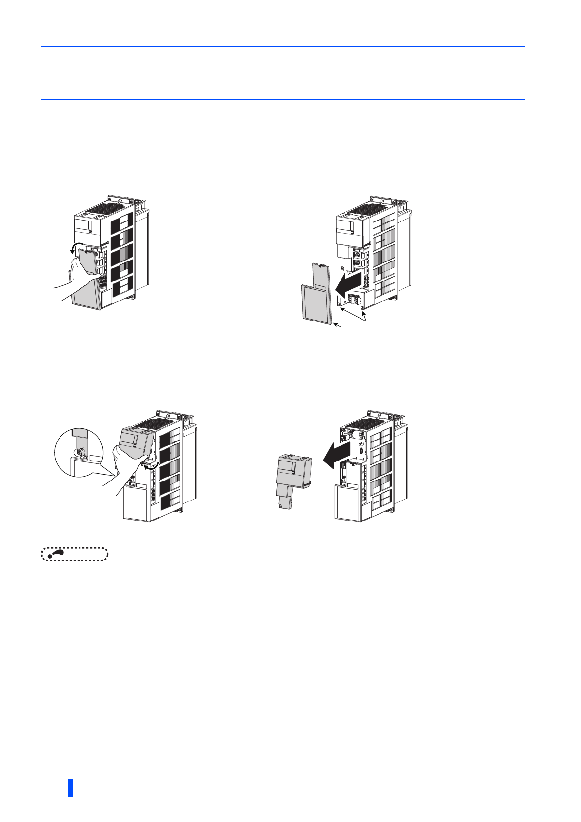
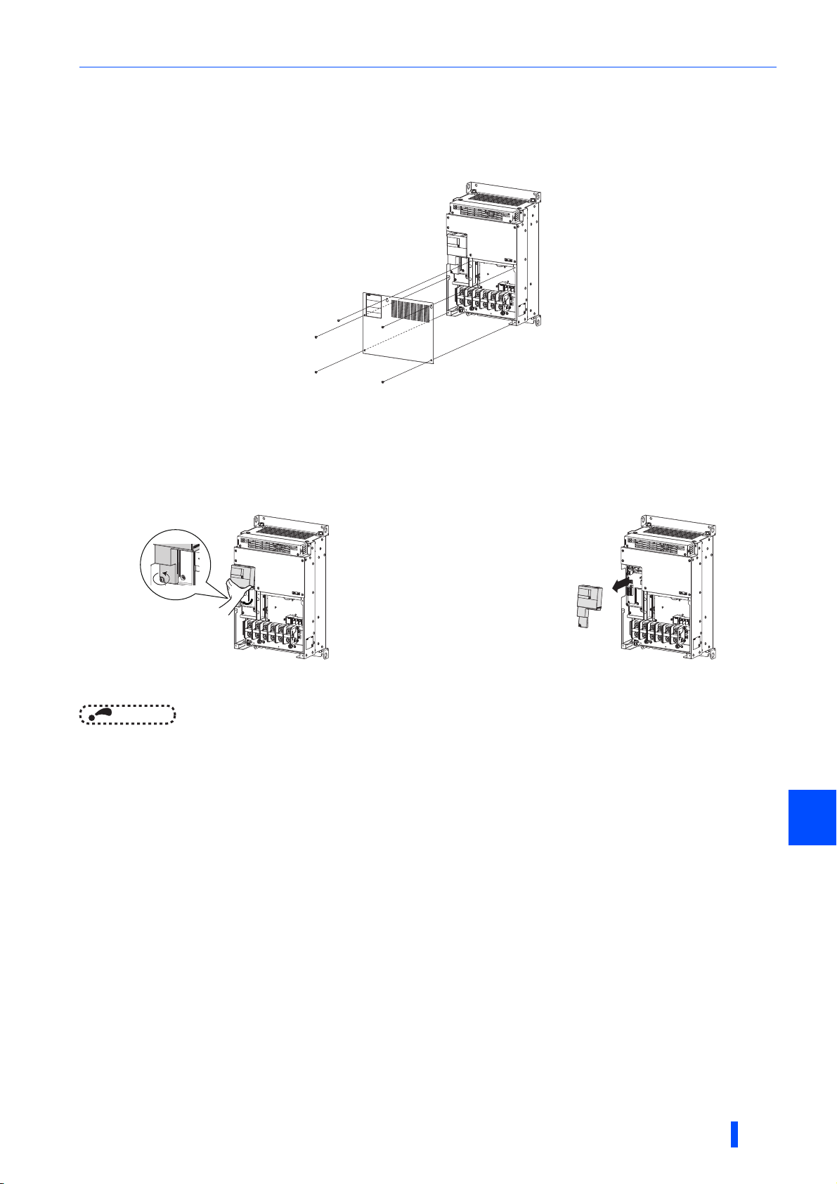
2.1.1 30K converters or lower
Main circuit terminal block cover
• To remove the cover, hold and pull out the upper part of
the cover.
To reinstall the cover, insert the hooks into the slots on the converter and push the cover to snap it into place.
• The hooks on the lower end of the cover snap out of
position. The cover is detached from the converter.
Slot
Hook
Control circuit terminal block cover
• To remove the cover, loosen the mounting screws of the
cover, and hold and pull out the lower part of the cover.
• The hooks on the upper end of the cover snap out of
position. The cover is detached from the converter.
To reinstall the cover, insert the hooks into the slots on the converter and push the cover to snap it into place.
NOTE
• After installing the cover, check that it is fixed securely in place. Always tighten the mounting screws of the cover.
26
INSTALLATION AND WIRING
Removal and reinstallation of the converter covers
2.1.2 37K converters or higher
Main circuit terminal block cover
• When the mounting screws are removed, the main circuit terminal block cover can be removed.
To reinstall the cover, insert the hooks into the slots on the converter and push the cover to snap it into place.
Control circuit terminal block cover
• To remove the cover, loosen the mounting screws of the
cover, and hold and pull out the lower part of the cover.
To reinstall the cover, insert the hooks into the slots on the converter and push the cover to snap it into place.
NOTE
• After installing the cover, check that it is fixed securely in place. Always tighten the mounting screws of the cover.
• The hooks on the upper end of the cover snap out of
position. The cover is detached from the converter.
2
INSTALLATION AND WIRING
27
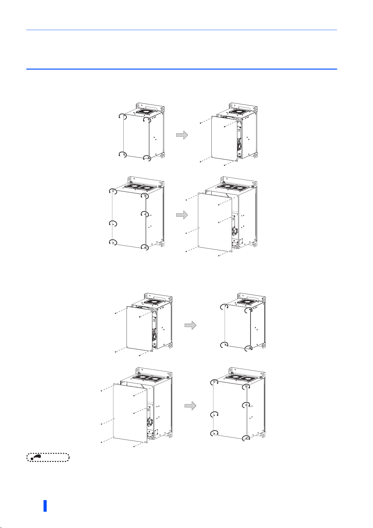
Removal and reinstallation of the FR-XCB reactor cover
2.2 Removal and reinstallation of the FR-XCB
reactor cover
Removal
• Loosen the mounting screws of the cover. • Pull out the cover to remove it.
●FR-XCB-(H)18.5K, 22K
Cover
●FR-XCB-(H)37K or higher
Cover
Reinstallation
• Align the screw holes on the cover with the holes on the
reactor, and place the cover back into position.
●FR-XCB-(H)18.5K, 22K
Cover
Cover
• Tighten the mounting screws of the cover (tightening
torque: 1.7 Nm).
Cover
●FR-XCB-(H)37K or higher
Cover
Cover
Cover
NOTE
• After installing the front cover, check that it is fixed securely in place. Always tighten the mounting screws of the cover.
• The capacity plate is placed on the cover, and the rating plate is on the remainder of the reactor box. Before reinstalling the
cover, check the serial number on the capacity plate against the one on the rating plate to make sure they are identical with
each other.
28
INSTALLATION AND WIRING
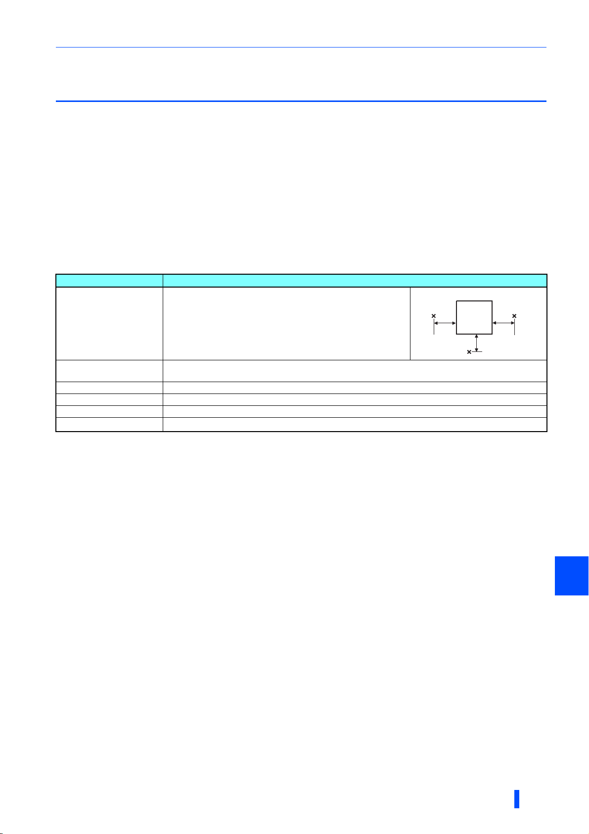
Installation of the converter and enclosure design
2.3 Installation of the converter and enclosure
design
When designing or manufacturing an enclosure, determine the structure, size, and device layout of the enclosure by fully
considering the conditions such as heat generation of the contained devices and the operating environment.
The multifunction regeneration converter unit uses many semiconductor devices. To ensure higher reliability and long period
of operation, operate the converter in the ambient environment that completely satisfies the equipment specifications.
2.3.1 Converter installation environment
The following table lists the standard specifications of the installation environment for the multifunction regeneration converter.
Using the converter in an environment that does not satisfy the conditions deteriorates the performance, shortens the life, and
causes a failure. Refer to the following points, and take adequate measures.
Standard environmental specifications of the converter
Item Description
Measurement
position
5 cm
Surrounding air temperature -10 to +50°C∗1 (non-freezing)
5 cm
Converter
5 cm
Ambient humidity
Storage temperature -20 to +65°C
Atmosphere Indoors (free from corrosive gas, flammable gas, oil mist, dust and dirt)
Altitude Maximum 2500 m
Vibration
∗1 -10 to +40°C (non-freezing) at the 40°C rating.
∗2 Temperature applicable for a short time, for example, in transit.
∗3 For the installation at an altitude above 1000 m, consider a 3% reduction in the rated current per 500 m increase in altitude.
With circuit board coating (conforming to IEC 60721-3-3 3C2/3S2): 95% RH or less (non-condensing)
Without circuit board coating: 90% RH or less (non-condensing)
∗2
∗3
2
5.9 m/s
or less at 10 to 55 Hz (directions of X, Y, Z axes)
Measurement
position
Temperatur e
The permissible surrounding air temperature of the multifunction regeneration converter is -10 to +50°C (-10 to +40°C at the
40°C rating). Always operate the converter within this temperature range. Operation outside this range will considerably
shorten the service lives of the semiconductors, parts, capacitors and others. Take the following measures to keep the
surrounding air temperature of the converter within the specified range.
(a) Measures against high temperature
• Use a forced ventilation system or similar cooling system. (Refer to page 31.)
• Install the enclosure in an air-conditioned electric chamber.
• Block direct sunlight.
• Provide a shield or similar plate to avoid direct exposure to the radiated heat and wind of a heat source.
• Ventilate the area around the enclosure well.
(b) Measures against low temperature
• Provide a space heater in the enclosure.
• Do not power OFF the converter. (Keep the start signal of the inverter OFF.)
(c) Sudden temperature changes
• Select an installation place where temperature does not change suddenly.
• Avoid installing the converter near the air outlet of an air conditioner.
• If temperature changes are caused by opening/closing of a door, install the converter away from the door.
2
INSTALLATION AND WIRING
29

Installation of the converter and enclosure design
Humidity
Operate the multifunction regeneration converter within the ambient air humidity of usually 45 to 90% (up to 95% with circuit
board coating). Too high humidity will pose problems of reduced insulation and metal corrosion. On the other hand, too low
humidity may cause a spatial electrical breakdown. The insulation distance defined in JEM 1103 "Control Equipment
Insulator" is humidity of 45 to 85%.
(a) Measures against high humidity
• Make the enclosure enclosed, and provide it with a hygroscopic agent.
• Provide dry air into the enclosure from outside.
• Provide a space heater in the enclosure.
(b) Measures against low humidity
Air with proper humidity can be blown into the enclosure from outside. Also when installing or inspecting the unit, discharge
your body (static electricity) beforehand, and keep your body away from the parts and patterns.
(c) Measures against condensation
Condensation may occur if frequent operation stops change the in-enclosure temperature suddenly or if the outside air
temperature changes suddenly.
Condensation causes such faults as reduced insulation and corrosion.
Measures
• Take the measures against high humidity in (a).
• Do not power OFF the converter. (Keep the start signal of the inverter OFF.)
Dust, dirt, oil mist
Dust and dirt will cause such faults as poor contacts, reduced insulation and cooling effect due to the moisture-absorbed
accumulated dust and dirt, and in-enclosure temperature rise due to a clogged filter. In an atmosphere where conductive
powder floats, dust and dirt will cause such faults as malfunction, deteriorated insulation and short circuit in a short time.
Since oil mist will cause similar conditions, it is necessary to take adequate measures.
Measures
• Place the converter in a totally enclosed enclosure.
Take measures if the in-enclosure temperature rises. (Refer to page 31.)
• Purge air.
Pump clean air from outside to make the in-enclosure air pressure higher than the outside air pressure.
Corrosive gas, salt damage
If the converter is exposed to corrosive gas or to salt near a beach, the printed board patterns and parts will corrode or the
relays and switches will result in poor contact.
In such places, take the measures given in the previous paragraph.
Explosive, flammable gases
As the multifunction regeneration converter is non-explosion proof, it must be contained in an explosion-proof enclosure. In
places where explosion may be caused by explosive gas, dust or dirt, an enclosure cannot be used unless it structurally
complies with the guidelines and has passed the specified tests. This makes the enclosure itself expensive (including the test
charges). The best way is to avoid installation in such places and install the converter in a non-hazardous place.
High altitude
Use the multifunction regeneration converter at an altitude of within 2500 m. For use at an altitude above 1000 m, consider a
3% reduction in the rated current per 500 m increase in altitude.
If it is used at a higher place, it is likely that thin air will reduce the cooling effect and low air pressure will deteriorate dielectric
strength.
30
INSTALLATION AND WIRING

Installation of the converter and enclosure design
Vibration, impact
The vibration resistance of the multifunction regeneration converter is up to 5.9 m/s2 at 10 to 55 Hz frequency and 1 mm
amplitude for the directions of X, Y, Z axes. Applying vibration and impacts for a long time may loosen the structures and
cause poor contacts of connectors, even if those vibration and impacts are within the specified values.
Especially when impacts are applied repeatedly, caution must be taken because such impacts may break the installation feet.
Measures
• Provide the enclosure with rubber vibration isolators.
• Strengthen the structure to prevent the enclosure from resonance.
• Install the enclosure away from the sources of the vibration.
2.3.2 Cooling system types for converter enclosure
From the enclosure that contains the multifunction regeneration converter, the heat of the converter and other equipment
(inverter, transformers, reactors, lamps, resistors, etc.) and the incoming heat such as direct sunlight must be dissipated to
keep the in-enclosure temperature lower than the permissible temperatures of the in-enclosure equipment including the
converter.
The cooling systems are classified as follows in terms of the cooling calculation method.
(a) Cooling by natural heat dissipation from the enclosure surface (totally enclosed type)
(b) Cooling by heatsink (aluminum fin, etc.)
(c) Cooling by ventilation (forced ventilation type, pipe ventilation type)
(d) Cooling by heat exchanger or cooler (heat pipe, cooler, etc.)
Natural
Forced air
Cooling system Enclosure structure Comment
Natural ventilation
(enclosed ventilated type)
Natural ventilation (totally
enclosed type)
Heatsink
Heatsink cooling
Forced ventilation
Heat pipe This is a totally enclosed for enclosure downsizing.
FR-XC
FR-XC
FR-XC
FR-XC
Heat pipe
FR-XC
This system is low in cost and generally used, but the
enclosure size increases as the converter capacity increases.
This system is for relatively small capacities.
Being a totally enclosed type, this system is the most
appropriate for hostile environment having dust, dirt, oil mist,
etc. The enclosure size increases depending on the converter
capacity.
This system has restrictions on the heatsink mounting position
and area. This system is for relatively small capacities.
This system is for general indoor installation. This is
appropriate for enclosure downsizing and cost reduction, and
often used.
2
INSTALLATION AND WIRING
31

Installation of the converter and enclosure design
A
2.3.3 Converter installation
Converter placement
FR-XC-(H)7.5K, (H)11K, (H)15K
FR-XC-(H)22K, (H)30K
FR-XC-(H)18.5K-PWM, (H)22K-PWM
FR-XC-(H)37K, (H)55K
FR-XC-(H)37K-PWM, (H)55K-PWM
• For the models up to 30K converters or lower, cut the enclosure according to the dimensions shown on page 34.
• Install the converter on a strong surface securely with screws.
• Leave enough clearances and take cooling measures.
• Avoid places where the converter is subjected to direct sunlight, high temperature and high humidity.
• Install the converter on a nonflammable wall surface.
• When encasing multiple converters in an enclosure, install them in parallel as a cooling measure.
• For heat dissipation and maintenance, keep clearance between the converter and the other devices or enclosure surface.
The clearance below the converter is required as a wiring space, and the clearance above the converter is required as a
heat dissipation space.
• When designing or building an enclosure for the converter, carefully consider influencing factors such as heat generation of
the contained devices and the operating environment.
Clearances (side)Clearances (front)
37K converters
or higher
5 cm
or more
Converter
llow clearance
Vertical
10 cm or more
5 cm or more 5 cm or more
10 cm or more
30K converters
or lower
5 cm
or more
Converter
10 cm or
more
5 cm or
more
Installation orientation of the converter
Install the converter on a wall as specified. Do not mount it horizontally or in any other way.
Above the converter
Heat is blown up from inside the converter by the small fan built in the unit. Any equipment placed above the converter should
be heat resistant.
32
INSTALLATION AND WIRING

Installation of the converter and enclosure design
Arrangement of multiple converter/inverter units
When multiple converter/inverter units are placed in the
same enclosure, generally arrange them horizontally as
shown in the figure (a). When it is inevitable to arrange
them vertically to minimize space, take such measures as
to provide guides since heat generated in the units in
bottom row can increase the temperatures in the units in
top row, causing the failure of the units in top row.
When installing multiple units, fully take measures to
prevent the surrounding air temperature of the units from
being higher than the permissible value by providing
ventilation or increasing the enclosure size.
Converter
Enclosure Enclosure
(a) Horizontal arrangement (b) Vertical arrangement
NOTE
• The FR-XCL and FR-XCB reactors also generate heat. To store the FR-XCL or FR-XCB in the enclosure that contains the
converter and inverter(s), measures against temperature rises are required as is the case with the converter and inverter(s).
Arrangement of the ventilation fan and converter
InverterInverter
Guide Guide
Converter Converter
Inverter
Guide
The air warmed by the heat generated inside the converter
goes up to the top of the enclosure. When installing a
ventilation fan for that heat, determine the place of ventilation
fan installation after fully considering an air flow. (Air passes
through areas of low resistance. Make an airway and airflow
plates to expose the converter to cool air.)
converter converter
<Good example> <Bad example>
converter converter
2
<Good example> <Bad example>
Arrangement of the ventilation fan and converter
INSTALLATION AND WIRING
33

Installation of the converter and enclosure design
(Unit: mm)
Multifunction regeneration
converter
W W1 H H1
FR-XC-(H)37K, FR-XC-H55K
FR-XC-(H)37K-PWM, FR-XC-H55K-PWM
315 270 490 530
FR-XC-55K
FR-XC-55K-PWM
360 300 560 600
2.3.4 Protruding the heat sink through a panel
When encasing the multifunction regeneration converter to an enclosure, the heat generated in the enclosure can be greatly
reduced by protruding the heat sink of the multifunction regeneration converter. (The 30K converters or lower are designed to
be installed in an enclosure with its heatsink protruded through the panel.)
When installing the multifunction regeneration converter in a compact enclosure, etc., this installation method is
recommended.
30K converters or lower
Refer to page 162 for instructions for cutting the panel of the enclosure.
NOTE
• Use the FR-XCCP, converter installation attachment for enclosure (option), to install the multifunction regeneration converter
inside the enclosure.
37K converters or higher
Panel cutting
Cut the panel of the enclosure as follows.
H1
H
20 20
W
W1
Hole
4-M8
34
INSTALLATION AND WIRING
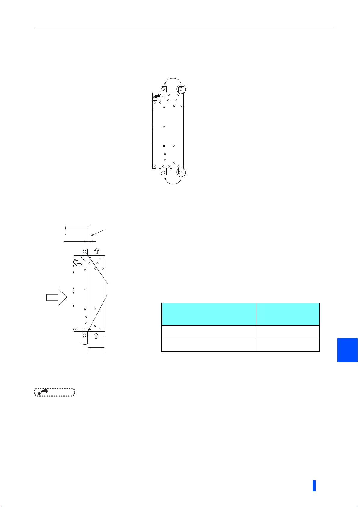
Installation of the converter and enclosure design
∗1 Dimension of the outside of the enclosure
∗2 To avoid interference with the cooling fan on top of the heatsink, the thickness of the rear
panel of the enclosure should not exceed 10 mm and the space around the fan should be
cleared.
Multifunction regeneration
converter
Dimension of the
outside of the
enclosure (mm)
FR-XC-(H)37K, FR-XC-H55K
FR-XC-(H)37K-PWM, FR-XC-H55K-PWM
105
FR-XC-55K
FR-XC-55K-PWM
135
Mount point change of installation frame from the rear to the front
The upper and lower installation frames are attached on the multifunction regeneration converter (one for each position).
Change the mount point of the upper and lower installation frames from the rear to the front as shown in the figure.
When reattaching the installation frames, make sure that the installation orientation is correct.
Shift
Upper
installation
frame
Lower
Shift
installation
frame
Installation of the multifunction regeneration converter on the enclosure
Push the multifunction regeneration converter heat sink part outside the enclosure, and fix the multifunction regeneration
converter to the panel with upper and lower installation frames.
Enclosure
Exhausted air
Installation
Cooling
wind
∗1
frame
Converter
Inside the
enclosure
10 mm∗2
2
NOTE
• As the heat sink part protruded through the panel includes a cooling fan, this type of installation is not suitable for the
environment of water drops, oil, mist, dust, etc.
• Be careful not to drop screws, dust etc. into the multifunction regeneration converter and cooling fan section.
INSTALLATION AND WIRING
35
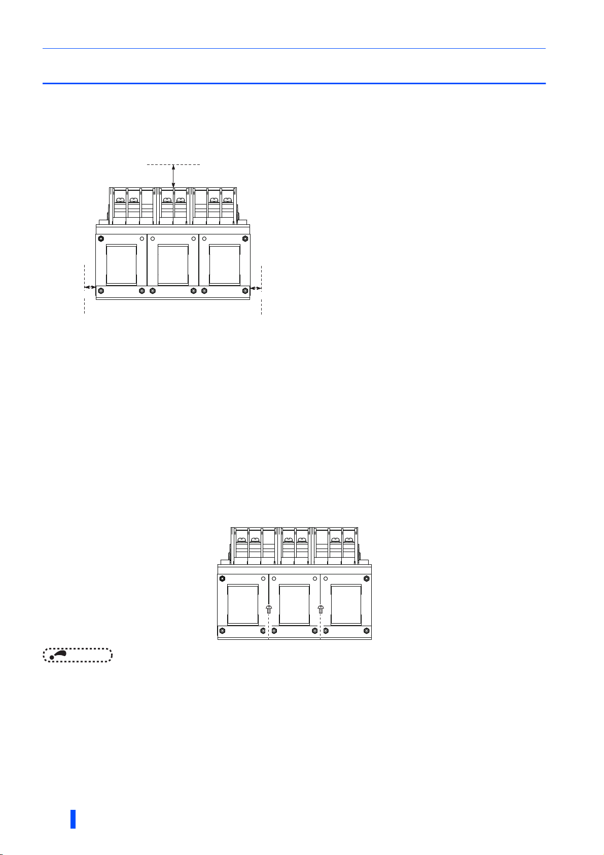
Installation of peripheral devices
2.4 Installation of peripheral devices
2.4.1 Installation of reactor (FR-XCL)
Clearances
Because the reactor generate heat, leave sufficient space around them.
10 cm or more
5 cm or more
5 cm or more
Installation place
Install the reactor on nonflammable material. Installing it directly on flammable material will cause a fire.
Surrounding environment
Avoid places where the equipment is subjected to oil mist, flammable gases, fluff, dust, dirt, etc.
Install the equipment in a clean place or protect it from suspended substances.
Installation orientation
To prevent looseness, install the reactor on a horizontal surface securely with screws or bolts.
Do not install it on a vertical surface. Install it on a mounting stand which can withstand its weight.
36
NOTE
• Since the charged section of the reactor is uncovered, fully protect it to prevent ground fault and electric shock.
INSTALLATION AND WIRING
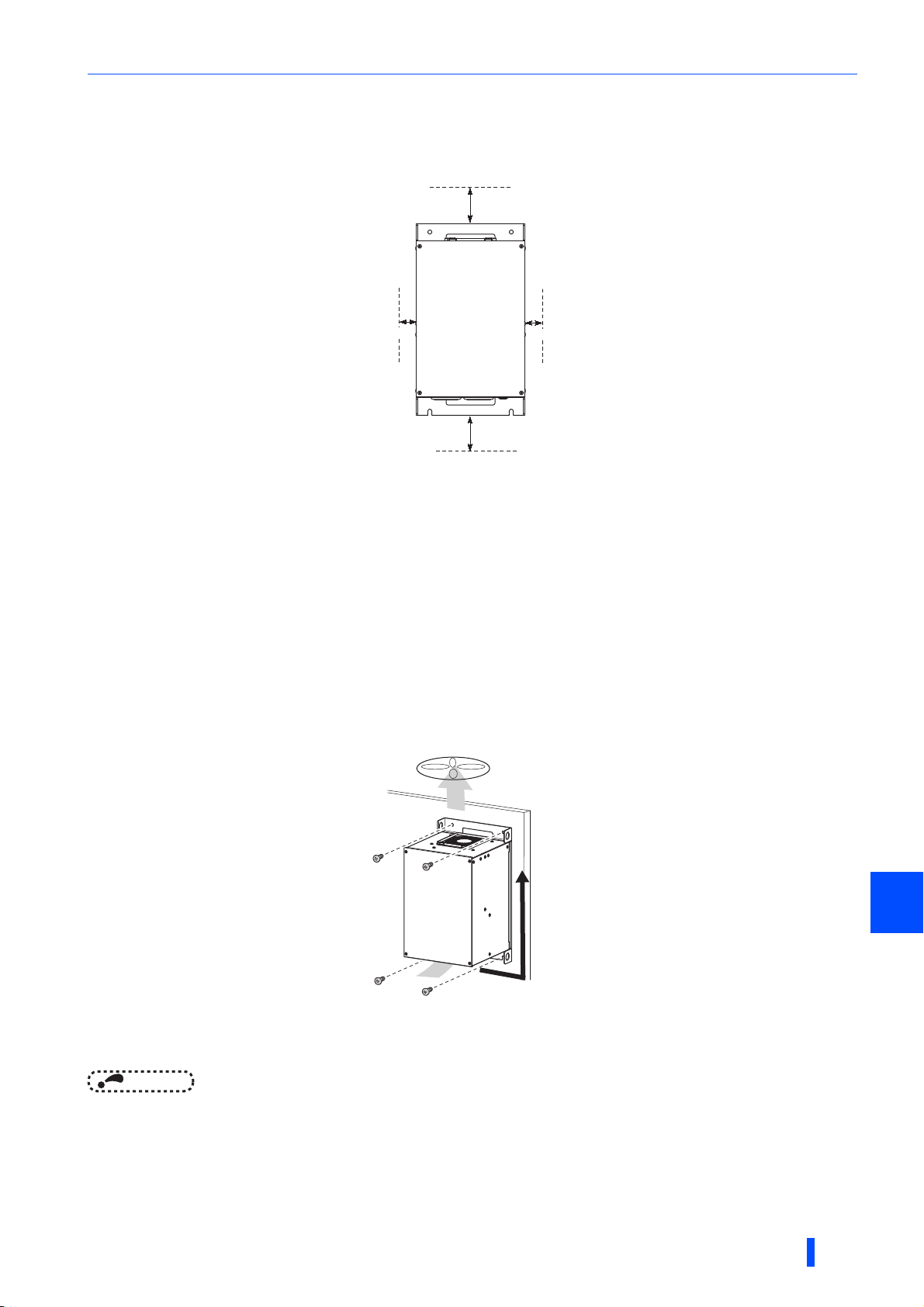
Installation of peripheral devices
2.4.2 Installation of box-type reactor (FR-XCB)
Clearances
10 cm or more
5 cm or more
10 cm or more
5 cm or more
Installation place
Install the reactor on nonflammable material. Installing it directly on flammable material will cause a fire.
Surrounding environment
Avoid places where the equipment is subjected to oil mist, flammable gases, fluff, dust, dirt, etc.
Install the equipment in a clean place or protect it from suspended substances.
Installation orientation
Install the reactor on a vertical surface.
Vertical
Wiring method
Make cuts in rubber bushes on the bottom of the reactor and lead the wires through the cuts.
NOTE
• To satisfy IP20 protection requirements, note the following points for wiring of the reactor.
- Do not make cuts in rubber bushes which are not used for wiring.
- Do not use the reactor with the rubber bushes removed.
INSTALLATION AND WIRING
2
37

Connection of the converter and the inverter
()
/
2.5
Connection of the converter and the inverter
2.5.1 Inverter selection
Connectable inverter models depend on the operation mode of the FR-XC series converter, the common bus
regeneration mode or the power regeneration mode.
Common bus regeneration mode
• Observe the following inverter selection conditions.
Item Condition
Inverter capacity
Motor rated
current
Number of
inverters
Inverter with the
HD rating
∗1 Note that the applicable inverter capacity and motor current are different depending on the harmonic suppression function condition of the FR-
NOTE
• For details of the inverter capacity, refer to the rating specifications in the Instruction Manual of the inverter.
The total capacity of the connected inverters (regardless of the rating or model of the inverters) must not exceed
the applicable inverter capacity (kW) shown in the converter's rated specifications (refer to
The total of the rated current of the connected motors (rated current for the selected rating) must not exceed
the applicable motor current (A) shown in the converter's rated specifications (refer to page 156).
The number of inverters actually connected must not exceed the number of connectable inverters shown in the
converter's rated specifications (refer to page 156).
For the HD rating, 200% of the total rated current of the connected motors must not exceed 150% of the
applicable motor current (A) shown in the converter's rated specifications.
XC-(H)22K, FR-XC-(H)30K, FR-XC-(H)18.5K-PWM, or FR-XC(H)22K-PWM converter (refer to page 156).
Example: FR-A820
Model FR-A820-[ ]
SLD 0.75 1.5 2.2
00046 00077 00105
0.4K 0.75K 1.5K
page 156
∗1
).
∗1
• For the FR-V500 inverter, the capacity used for selection is as follows.
Capacity of the FR-V500 (kW)
Capacity used for selection (kW)
• Refer to page 67 and page 156 for the details of the applicable inverter capacity, the applicable inverter current, and the
number of connectable inverters.
• The power factor improving AC reactor or DC reactor cannot be used.
1.52.23.75.57.5111518.52230374555
2.2 3.7 5.5 7.5 11 15 18.5 22 30 37 45 55 55
Power regeneration mode
• Follow the following steps to confirm your converter selection and select the FR-HAL AC reactor.
1) Check the value of the potential regenerative capacity (kW) and the overload current rating of the converter you have
(on page 156). Confirm that you have selected the right converter with larger capacity than a motor capacity.
Selection example:
For a motor which can supply 10 kW regenerative power with an overload capacity of 120% (12 kW) for 60 seconds,
the FR-XC-15K (15 kW converter) should be selected.
Model FR-XC-[ ]K
Applicable inverter
capacity (kW)
Potential regenerative capacity (kW)
Rated current (A) (regenerative driving)
∗1
Harmonic suppression
Disabled
Enabled
∗7
7.5 11 15 22 30 37 55
7.5111522303755
⎯ ⎯ ⎯ 18.5 22 37 55
5.5 7.5 11 18.5 22 30 45
19 26 37 62 74 102 152
38
Overload current rating
50°C rating
Potential regenerative capacity (kW)
Rated current (A) (regenerative driving)
Overload current rating
Power regeneration mode
40°C rating
Rated input AC voltage
INSTALLATION AND WIRING
100% continuous / 150% 60 s
5.5 7.5 11 18.5 22 30 45
21 28 40 68 81 112 167
100% continuous / 150% 60 s
Disabled
Three-phase 200 to 240 V, 50/60 Hz

Connection of the converter and the inverter
2) Select the FR-HAL with appropriate capacity according to the capacity (model) of the motor and the converter.
200 V class
Multifunction
regeneration
converter
FR-XC-7.5K
FR-XC-11K
FR-XC-15K
FR-XC-22K
FR-XC-18.5K-PWM
FR-XC-30K
FR-XC-22K-PWM
FR-XC-37K
FR-XC-37K-PWM
FR-XC-55K
FR-XC-55K-PWM
400 V class
Multifunction
regeneration
converter
FR-XC-H7.5K
FR-XC-H11K
FR-XC-H15K
FR-XC-H22K
FR-XC-H18.5K-PWM
FR-XC-H30K
FR-XC-H22K-PWM
FR-XC-H37K
FR-XC-H37K-PWM
FR-XC-H55K
FR-XC-H55K-PWM
AC reactor
FR-HAL-[]K
Quantity 12233
FR-HAL-[]K
Quantity 12233
FR-HAL-[]K
Quantity 12233
FR-HAL-[]K
Quantity 12233
FR-HAL-[]K
Quantity 12233
FR-HAL-[]K
Quantity 12233
FR-HAL-[]K
Quantity 122
AC reactor
FR-HAL-H[]K
Quantity 12233
FR-HAL-H[]K
Quantity 12233
FR-HAL-H[]K
Quantity 12233
FR-HAL-H[]K
Quantity 12233
FR-HAL-H[]K
Quantity 12233
FR-HAL-H[]K
Quantity 12233
FR-HAL-H[]K
Quantity 12233
7.5K 11K 15K 18.5K 22K 30K 37K 45K 55K 75K 90K 110K
11 15 18.5 22 30
⎯
⎯⎯
⎯⎯⎯
⎯⎯⎯⎯⎯
⎯⎯⎯⎯⎯⎯
⎯⎯⎯⎯⎯⎯⎯
⎯⎯⎯⎯⎯⎯⎯⎯⎯
× : Invalid combination regardless of the converter operation mode.
⎯ : Invalid combination in the power regeneration mode. (Check the inverter models applicable to the
7.5K 11K 15K
11 15 18.5 22 30
⎯
⎯⎯
⎯⎯⎯
⎯⎯⎯⎯⎯
⎯⎯⎯⎯⎯⎯
⎯⎯⎯⎯⎯⎯⎯
⎯⎯⎯⎯⎯⎯⎯⎯⎯
× : Invalid combination regardless of the converter operation mode.
⎯ : Invalid combination in the power regeneration mode. (Check the inverter models applicable to the
15 18.5 22 30 37
18.522303745
converter in the common bus regeneration mode.)
18.5
22K 30K 37K 45K 55K 75K 90K
K
15 18.5 22 30 37
18.522303745
converter in the common bus regeneration mode.)
Motor capacity
ЧЧЧЧЧЧ
ЧЧЧЧЧ
××××
30 37 45 55 75
37 45 55 75 110
45 55 75 110 110
75 110 110
Motor capacity
110K132K160
ЧЧЧЧЧЧЧЧЧ
ЧЧЧЧЧЧЧЧ
ЧЧЧЧЧЧЧ
30 37 45 55 75
37 45 55 75 110
45 55 75 110 110
ЧЧЧЧЧ
××××
75 110 110 185 185
××
×
185
K or
high
K
er
×××
×
NOTE
• For information of the installation location of the AC reactor, refer to page 58.
To install multiple AC reactors in a system, connect them in series.
• When using a 75 kW inverter/motor or higher, also install the FR-HEL DC reactor (refer to the inverter instruction manuals).
INSTALLATION AND WIRING
2
39

Connection of the converter and the inverter
2.5.2 Switching between the common bus
regeneration mode and the power regeneration
mode
• Switch the converter connection mode between the common bus regeneration mode
and the power regeneration mode by changing the position of switch 1 in the function
selection switch assembly (SW2).
Common bus
regeneration mode
NOTE
• The new setting of the switch is applied at the next power-ON or converter reset.
• If the switch 1 setting (the connection mode setting) does not match the actual wiring of the main circuit terminals, the
connection mode fault "E.T" occurs.
2.5.3 Function enable/disable selection (Pr.416)
• Select the function status by setting Pr.416.
Pr.416 setting Function
0
1
9999 (initial value)
NOTE
• The change of the Pr.416 setting is applied at the next power-ON or converter reset.
• If the harmonic suppression function is attempted to be enabled in the FR-XC-15K or lower, the fault "E.U" (Unsupported
function selected) occurs.
Harmonic suppression disabled
Harmonic suppression enabled
FR-XC-[ ]K: Harmonic suppression disabled
FR-XC-[ ]K-PWM: Harmonic suppression enabled
Check the model of the multifunction regeneration converter described on the rating plate (refer to page
10).
Power regeneration
mode
2.5.4 Inverter parameter settings
To use the converter with the inverter, Pr.30 Regenerative function selection in the inverter parameters must be set. The
parameter setting differ by the inverter series.
Refer to the Instruction Manual of the Inverter.
• To use the converter in the common bus regeneration mode, select the setting for a power regeneration common converter
or high power factor converter (Example: Pr.30 in the FR-A800 = "2"). When Pr.416 = "1", set the rated motor voltage in
Pr.19 Base frequency voltage (under V/F control) or Pr.83 Rated motor voltage (under control other than V/F control).
• To use the converter in the power regeneration mode, set "0" in Pr.30 in any inverter irrespective of model and capacity.
NOTE
•Set
Pr.30
in the inverter parameters correctly according to the converter operation mode (common bus regeneration mode or
power regeneration mode). Incorrect setting may disrupt normal operation.
2.5.5 Temperature derating selection
The temperature rating changes according to the setting position of the switch 3 in the function selection switch assembly
(SW2).
When the 40°C rating is selected, the rated current and the applied current can be increased.
When the 40°C rating is selected, the surrounding air temperature must be between -10 and +40°C (non-freezing).
NOTE
50°C rating
• The new setting of the switch is applied at the next power-ON or converter reset.
40℃ rating
40
INSTALLATION AND WIRING

Main circuit terminal specification
P/+
P4
N/-
R/L1
S/L2
T/L3
R1/L11
S1/L21
R2/L12 S2/L22 T2/L32
Charge lamp
Earth (ground) terminal
(for 7.5K *1)
Earth (ground) term
(for 11K *2)
P/+
P4
N/-
R/L1
S/L2
T/L3
R1/L11
S1/L21
R2/L12 S2/L22 T2/L32
Charge lamp
Earth (ground) terminal
2.6 Main circuit terminal specification
2.6.1 Details on the main circuit terminals
Ter min al
symbol
R/L1,
S/L2,
T/L3
R2/L12, S2/
L22, T2/L32
R1/L11, S1/
L21
P/+, N/-
P4, N/-
Terminal name Description
These terminals are used to detect the phase and voltage of the power supply, and to input
Power supply phase
detection
AC power input Connect each of them to terminals of the same name on the reactor.
Power supply for the
control circuit
DC power supply for
the common bus
regeneration mode
DC power supply for
the power
regeneration mode
Earth (ground) For earthing (grounding) the converter chassis. This must be earthed (grounded).
power to the control circuit. Connect each of them to terminals of the same name on both
the power supply and the reactor. Operating the inverter without connecting them will
damage the converter.
These terminals are connected to the phase detection terminals R/L1 and S/L2 in the initial
status. To retain the fault display and fault output, remove the jumpers (cables) and apply
external power through these terminals.
Connect them to the inverter terminals P/+ and N/-.
Connect them to the inverter terminals P/+ and N/-.
2.6.2 Main circuit terminal block layout
FR-XC-(H)7.5K, (H)11K FR-XC-(H)15K
∗1 Screws for earthing (grounding) for the 7.5K
∗2 Screws for earthing (grounding) for the 11K
INSTALLATION AND WIRING
2
41

Main circuit terminal specification
P/+
P4
N/-
R/L1
S/L2
T/L3
R1/L11
S1/L21
R2/L12 S2/L22 T2/L32
Earth (ground) terminal
Charge lamp
R/L1S/
L2
Earth (ground) terminal
Charge lamp
R2/L12 S2/L22 T2/L32 P/+ P4N/-
T/
L3
R1/
L11
S1/
L21
FR-XC-(H)22K-(H)30K
FR-XC-(H)18.5K-PWM, (H)22K-PWM
FR-XC-(H)37K, (H)55K
FR-XC-(H)37K-PWM-(H)55K-PWM
42
INSTALLATION AND WIRING

Main circuit terminal specification
2.6.3 Cable size of the main circuit terminals and the
earth (ground) terminal
Screw size
• 200 V class (220 V power reception)
Model
FR-XC-7.5K
FR-XC-11K
FR-XC-15K
FR-XC-22K
FR-XC-18.5K-PWM
FR-XC-30K
FR-XC-22K-PWM
FR-XC-37K
FR-XC-37K-PWM
FR-XC-55K
FR-XC-55K-PWM
Terminal screw size (Tightening torque (N·m))
R, S, T
M4 (1.5)
R2, S2, T2
M5 (2.5)
M8 (7.8) M6 (4.4)
M10 (14.7) M10 (14.7)
M12 (24.5) M12 (24.5) FR-XCL-55K
P4, P, N R1, S1
M6 (4.4)
• 400 V class (440 V power reception)
Terminal screw size (Tightening torque (N·m))
Model
FR-XC-H7.5K
FR-XC-H11K
FR-XC-H15K
FR-XC-H22K
FR-XC-H18.5KPWM
FR-XC-H30K
FR-XC-H22K-PWM
FR-XC-H37K
FR-XC-H37K-PWM
FR-XC-H55K
FR-XC-H55K-PWM
R, S, T
M4 (1.5)
R2, S2, T2
M5 (2.5)
M8 (7.8)
P4, P, N R1, S1
M6 (4.4)
M8 (7.8) M8 (7.8)
M4 (1.5)
M4 (1.5)
Model
Earth
(ground)
M4 (1.5) FR-XCL-7.5K
M5 (2.5)
M8 (7.8)
Earth
(ground)
M4 (1.5) FR-XCL-H7.5K
M5 (2.5)
M6 (4.4)
FR-XCL-11K FR-XCB-22K
FR-XCL-15K
FR-XCL-22K FR-XCB-55K
FR-XC-L30K
FR-XCL-37K
Model
FR-XCL-H11K FR-XCB-H22K
FR-XCL-H15K FR-XCB-H37K
FR-XCL-H22K
FR-XCL-H30K
FR-XCL-H37K
FR-XCL-H55K
Terminal screw
size
(Tightening
torque (N·m))
R, S, T
R2, S2, T2
M5 (2.5)
M6 (4.4)
M10 (14.7)
Terminal screw
size
(Tightening
torque (N·m))
R, S, T
R2, S2, T2
M5 (2.5)
M6 (4.4)
M8 (7.8)
Model
FR-XCB-18.5K
FR-XCB-37K
Model
FR-XCB-H18.5K
FR-XCB-H55K
Terminal screw size
(Tightening torque
(N·m))
R, S, T
R2, S2, T2
M8 (7.8) M6 (4.4)
M10 (14.7) M8 (7.8)
Terminal screw size
(Tightening torque
R, S, T
R2, S2, T2
M6 (4.4) M6 (4.4)
M8 (7.8) M8 (7.8)
Earth
(ground)
(N·m))
Earth
(ground)
INSTALLATION AND WIRING
2
43

Main circuit terminal specification
Cable size, crimp terminal size
Select a recommended gauge size cable to ensure that the voltage drop ratio is within 2%.
The following indicates selection examples when the wiring length from the power supply to the converter is 20 m.
Common bus regeneration mode with harmonic suppression disabled
Inverter
R/L1
S/L2
T/L3
R1/L11
S1/L21
Fuse
P/+
Fuse
N/-
c: FR-XC to inverter
Model Rating
FR-XCL-7.5K
FR-XCL-11K
FR-XCL-15K
FR-XCL-22K
FR-XCL-30K
FR-XCL-37K
FR-XCL-55K
50°C
40°C
50°C
40°C
50°C
50°C
50°C
50°C
50°C
PVC cables, etc. (mm2) ∗3
Location in the
connection diagram
16 50 70 1.5 35
• 200 V class
Model Rating
FR-XC-7.5K
FR-XC-11K
FR-XC-15K
FR-XC-22K
FR-XC-18.5K-PWM
FR-XC-30K
FR-XC-22K-PWM
FR-XC-37K
FR-XC-37K-PWM
FR-XC-55K
FR-XC-55K-PWM
Model Rating
FR-XC-7.5K
FR-XC-11K
FR-XC-15K
FR-XC-22K
FR-XC-18.5K-PWM
FR-XC-30K
FR-XC-22K-PWM
FR-XC-37K
FR-XC-37K-PWM
FR-XC-55K
FR-XC-55K-PWM
Power
supply
b: FR-XCL to FR-XC
MCCB
MC
Fuse
Fuse
Fuse
a: Power supply to
FR-XCL
FR-XCL
R/L1
S/L2
T/L3
d: Power supply to FR-XC
R2/L12
S2/L22
T2/L32
R2/L12
S2/L22
T2/L23
R/L1
S/L2
T/L3
R1/L11
S1/L21
FR-XC
P4
P/+
N/-
Crimp terminal (for HIV cables, etc.)
R, S, T R2, S2, T2 P, N R1, S1
50°C
40°C
50°C
40°C
50°C
40°C 40°C
50°C
40°C 40°C
50°C
40°C 40°C
50°C
40°C 40°C
50°C
40°C 40°C
1.25-4
1.25-4 14-5 14-6 1.25-4
1.25-4 22-5 22-6 1.25-4 14-5
1.25-4 38-8 38-6 1.25-4 22-6
1.25-4 60-8 60-6 1.25-4 22-6
1.25-4 80-10 80-10 1.25-4 22-8
1.25-4 100-10 100-10 1.25-4 22-8
8-5
5.5-5 5.5-4
8-6 1.25-4
Earth
(ground)
5.5-4
8-5
8-5
Cable gauge
AWG/MCM ∗2
Location in the
connection diagram
1
1/0
1/016 35 501.525
2/0
3/0
50°C
40°C
50°C
40°C
50°C
40°C
50°C
40°C
50°C
40°C
50°C
40°C
50°C
40°C
HIV cables, etc. (mm2)∗1
Location in the
connection diagram
a, b c ∗4 d a, b c d a, b c d
8
5.5
14 14 1.25 8 6 6 16 10 16 1.5 16
22 22 1.25 14 4 4 16 16 25 1.5 16
38 38 1.25 22 2 2 16 25 25 1.5 16
60 60 1.25 22
80 80 1.25 22 2/0
100 100 1.25 38 4/0 4/0 16 95 95 1.5 50
8 1.25 5.5 8 8 16 10 10 1.5 10
Earth
(ground)
IM
M
Crimp terminal
(for HIV cables, etc.)
R, S, T, R2, S2, T2
8-5
5.5-5
14-5
22-6
38-6
60-6
80-10
100-10
Earth
(ground)
44
∗1 It is the gauge of a cable with the continuous maximum permissible temperature of 75°C (HIV cable (600 V grade heat-resistant PVC insulated
wire), etc.). It assumes a surrounding air temperature of 50°C or less (40°C or less for the 40°C rating) and the wiring distance of 20 m or less
from the power supply to the converter.
∗2 The cable size is that of the THHW cable with continuous maximum permissible temperature of 75°C. It assumes a surrounding air temperature
of 40°C or less and the wiring distance of 20 m or less from the power supply to the converter.
(For the use in the United States or Canada, refer to page 179.)
INSTALLATION AND WIRING

∗3 For the FR-XC-15K or lower, it is the gauge of a cable with the continuous maximum permissible temperature of 70°C (PVC cable). It assumes
∗4 If a cable thinner than the recommended cable size is used, it may not be protected by the DC fuse. (Refer to page 21 for the fuse selection.)
• 400 V class
Model Rating
FR-XC-H7.5K
FR-XC-H11K
FR-XC-H15K
FR-XC-H22K
FR-XC-H18.5K-PWM
FR-XC-H30K
FR-XC-H22K-PWM
FR-XC-H37K
FR-XC-H37K-PWM
FR-XC-H55K
FR-XC-H55K-PWM
Main circuit terminal specification
a surrounding air temperature of 40°C or less and the wiring distance of 20 m or less from the power supply to the converter.
For the FR-XC-22K / FR-XC-18.5K-PWM or higher, it is the gauge of a cable with the continuous maximum permissible temperature of 90°C
(PVC cable). It assumes a surrounding air temperature of 40°C or less and the wiring distance of 20 m or less from the power supply to the
converter.
(Selection example mainly for use in Europe.)
Crimp terminal (for HIV cables, etc.)
R, S, T R2, S2, T2 P, N R1, S1
50°C
40°C 40°C
50°C
40°C 40°C
50°C
40°C 40°C
50°C
40°C 40°C
50°C
40°C 40°C
50°C
40°C 40°C
50°C
40°C 40°C
1.25-4 3.5-5 3.5-6 1.25-4 3.5-4
1.25-4 5.5-5 5.5-6 1.25-4 5.5-5
1.25-4 8-5 8-6 1.25-4 5.5-5
1.25-4 14-8 22-6 1.25-4 14-6
1.25-4 22-8 22-6 1.25-4 14-6
1.25-4 38-8 38-8 1.25-4 14-8
1.25-4 60-8 60-8 1.25-4 22-8
Earth
(ground)
Model Rating
FR-XCL-H7.5K
FR-XCL-H11K
FR-XCL-H15K
FR-XCL-H22K
FR-XCL-H30K
FR-XCL-H37K
FR-XCL-H55K
50°C
50°C
50°C
50°C
50°C
50°C
50°C
Crimp terminal
(for HIV cables, etc.)
R, S, T, R2, S2, T2
3.5-5
5.5-5
8-5
14-6
22-6
38-8
60-8
Cable gauge
Model Rating
FR-XC-H7.5K
FR-XC-H11K
FR-XC-H15K
FR-XC-H22K
FR-XC-H18.5K-PWM
FR-XC-H30K
FR-XC-H22K-PWM
FR-XC-H37K
FR-XC-H37K-PWM
FR-XC-H55K
FR-XC-H55K-PWM
∗1 It is the gauge of a cable with the continuous maximum permissible temperature of 75°C (HIV cable (600 V grade heat-resistant PVC insulated
wire), etc.). It assumes a surrounding air temperature of 50°C or less (40°C or less for the 40°C rating) and the wiring distance of 20 m or less
from the power supply to the converter.
∗2 The cable size is that of the THHW cable with continuous maximum permissible temperature of 75°C. It assumes a surrounding air temperature
of 40°C or less and the wiring distance of 20 m or less from the power supply to the converter.
(For the use in the United States or Canada, refer to page 179.)
∗3 For the FR-XC-15K or lower, it is the gauge of a cable with the continuous maximum permissible temperature of 70°C (PVC cable). It assumes
a surrounding air temperature of 40°C or less and the wiring distance of 20 m or less from the power supply to the converter.
For the FR-XC-22K / FR-XC-18.5K-PWM or higher, it is the gauge of a cable with the continuous maximum permissible temperature of 90°C
(PVC cable). It assumes a surrounding air temperature of 40°C or less and the wiring distance of 20 m or less from the power supply to the
converter.
(Selection example mainly for use in Europe.)
∗4 If a cable thinner than the recommended cable size is used, it may not be protected by the DC fuse. (Refer to page 21 for the fuse selection.)
50°C
40°C
50°C
40°C
50°C
40°C
50°C
40°C
50°C
40°C
50°C
40°C
50°C
40°C
Location in the
connection diagram
a, b c ∗4 d a, b c d a, b c d
3.5 3.5 1.25 3.5 12 12 16 4 4 1.5 4
5.5 5.5 1.25 5.5 10 10 16 6 6 1.5 6
8 8 1.25 5.5 8 8 16 10 10 1.5 10
14 22 1.25 14 6 6 16 10 16 1.5 16
22 22 1.25 14 4 4 16
38 38 1.25 14
60 60 1.25 22 2
Earth
(ground)
HIV cables, etc. (mm2)∗1
AWG/MCM ∗2
Location in the
connection diagram
4
235
216
2
16 35
15025
PVC cables, etc. (mm2) ∗3
Location in the
connection diagram
16
25
25
25 1.5 16
35 1.5 16
35
1.5
Earth
(ground)
16
2
INSTALLATION AND WIRING
45

Main circuit terminal specification
Common bus regeneration mode with harmonic suppression enabled
Inverter
R/L1
Fuse
Fuse
S/L2
T/L3
R1/L11
S1/L21
P/+
N/-
Power
supply
MCCB
MC
a: Power supply to FR-XCB
Fuse
Fuse
Fuse
R/L1
S/L2
T/L3
FR-XCB
R2/L12
S2/L22
T2/L32
b: FR-XCB to FR-XC
FR-XC
R2/L12
S2/L22
T2/L32
P4
P/+
N/-
IM
M
• 200 V class
Model Rating
FR-XC-22K
FR-XC-18.5K-PWM
FR-XC-30K
FR-XC-22K-PWM
FR-XC-37K
FR-XC-37K-PWM
FR-XC-55K
FR-XC-55K-PWM
Model Rating
FR-XC-22K
FR-XC-18.5K-PWM
FR-XC-30K
FR-XC-22K-PWM
FR-XC-37K
FR-XC-37K-PWM
FR-XC-55K
FR-XC-55K-PWM
d: Power supply to FR-XC
R/L1
S/L2
T/L3
R1/L11
S1/L21
c: FR-XC to inverter
Crimp terminal (for HIV cables, etc.)
R, S, T
50°C
40°C 40°C
50°C
40°C 40°C
50°C
40°C 40°C
50°C
40°C 40°C
1.25-4 22-8 38-6 1.25-4 22-6
1.25-4 38-8 38-6 1.25-4 22-6
1.25-4 60-10 80-10 1.25-4 22-8
1.25-4 100-12 100-12 1.25-4 38-8
R2, S2,
T2
P, N R1, S1
Earth
(ground)
Model Rating
FR-XCB-18.5K
FR-XCB-22K
FR-XCB-37K
FR-XCB-55K
50°C
50°C
50°C
50°C
Cable gauge
AWG/MCM ∗2
Location in the
connection diagram
4
225
4
225
1/0 2/0
2/0 3/0
3/0
4/0
216
4/016 70 951.550
16 16
16 50 70 1.5 35
PVC cables, etc. (mm2) ∗3
Location in the
connection diagram
16
16
25 1.5 25
50°C
40°C
50°C
40°C
50°C
40°C
50°C
40°C
HIV cables, etc. (mm2)∗1
Location in the
connection diagram
a, b c ∗4 d a, b c d a, b c d
22 38 1.25 22 4
38 38 1.25 22
60 80 1.25 22
100 100 1.25 38
Earth
(ground)
Crimp terminal
(for HIV cables, etc.)
R, S, T
R2, S2, T2
22-8 22-6
38-8 22-6
60-10 22-8
100-10 38-8
Earth
(ground)
Earth
(ground)
1.5 16
46
∗1 It is the gauge of a cable with the continuous maximum permissible temperature of 75°C (HIV cable (600 V grade heat-resistant PVC insulated
wire), etc.). It assumes a surrounding air temperature of 50°C or less (40°C or less for the 40°C rating) and the wiring distance of 20 m or less
from the power supply to the converter.
∗2 It is the gauge of the cable with continuous maximum permissible temperature of 75°C (THHW cable). It assumes a surrounding air temperature
of 40°C or less and the wiring distance of 20 m or less from the power supply to the converter.
(For the use in the United States or Canada, refer to page 179.)
∗3 It is the gauge of a cable with the continuous maximum permissible temperature of 90°C (PVC cable). It assumes a surrounding air temperature
of 40°C or less and the wiring distance of 20 m or less from the power supply to the converter.
(Selection example mainly for use in Europe.)
∗4 If a cable thinner than the recommended cable size is used, it may not be protected by the DC fuse. (Refer to page 21 for the fuse selection.)
INSTALLATION AND WIRING

• 400 V class
FR-XC-H22K
FR-XC-H18.5K-PWM
FR-XC-H30K
FR-XC-H22K-PWM
FR-XC-H37K
FR-XC-H37K-PWM
FR-XC-H55K
FR-XC-H55K-PWM
FR-XC-H22K
FR-XC-H18.5K-PWM
FR-XC-H30K
FR-XC-H22K-PWM
FR-XC-H37K
FR-XC-H37K-PWM
FR-XC-H55K
FR-XC-H55K-PWM
Model Rating
50°C
40°C 40°C
50°C
40°C
50°C
40°C 40°C
50°C
40°C
Model Rating
50°C
40°C
50°C
40°C
50°C
40°C
50°C
40°C
Main circuit terminal specification
Crimp terminal (for HIV cables, etc.)
R, S, T
1.25-4 8-8 14-6 1.25-4 8-6
1.25-4 14-8
1.25-4 22-8 38-8 1.25-4 14-8
1.25-4
R2, S2,
T2
60-8
38-8
P, N R1, S1
22-6
14-6
60-8 1.25-4 22-8
1.25-4 14-6
Earth
(ground)
Model Rating
FR-XCB-H18.5K
FR-XCB-H22K
FR-XCB-H37K
FR-XCB-H55K
50°C
50°C
40°C
50°C
50°C
40°C
Cable gauge
HIV cables, etc. (mm2)∗1
Location in the
connection diagram
a, b
c ∗4
8
14
22 38 1.25 14 4 2 16 25 35 1.5 16
60
38 1
14 1.25 8 8 6 16 10 10 1.5 10
22
14 4
60 1.25 22 2
Earth
(ground)
d a, b c d a, b c d
1.25 14 6
AWG/MCM ∗2
Location in the
connection diagram
6
2
PVC cables, etc. (mm2) ∗3
Location in the
connection diagram
16 10 16 1.5 10
16 25 35 1.25 25
Crimp terminal
(for HIV cables, etc.)
R, S, T
R2, S2, T2
8-6 8-6
14-6 14-6
22-8 14-8
60-8
38-8
Earth
(ground)
22-8
Earth
(ground)
∗1 It is the gauge of a cable with the continuous maximum permissible temperature of 75°C (HIV cable (600 V grade heat-resistant PVC insulated
wire), etc.). It assumes a surrounding air temperature of 50°C or less (40°C or less for the 40°C rating) and the wiring distance of 20 m or less
from the power supply to the converter.
∗2 It is the gauge of the cable with continuous maximum permissible temperature of 75°C (THHW cable). It assumes a surrounding air temperature
of 40°C or less and the wiring distance of 20 m or less from the power supply to the converter.
(For the use in the United States or Canada, refer to page 179.)
∗3 It is the gauge of a cable with the continuous maximum permissible temperature of 90°C (PVC cable). It assumes a surrounding air temperature
of 40°C or less and the wiring distance of 20 m or less from the power supply to the converter.
(Selection example mainly for use in Europe.)
∗4 If a cable thinner than the recommended cable size is used, it may not be protected by the DC fuse. (Refer to page 21 for the fuse selection.)
2
INSTALLATION AND WIRING
47
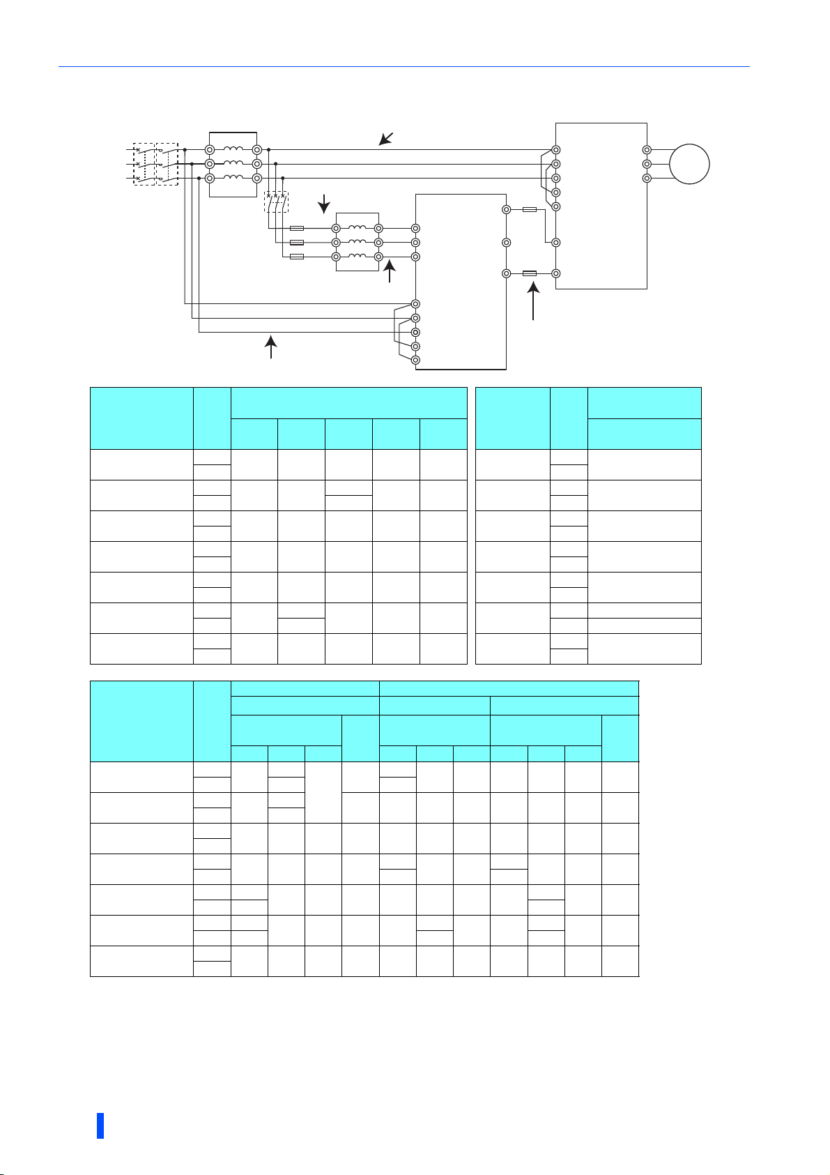
Main circuit terminal specification
Power regeneration mode
Power
supply
• 200 V class
Model
FR-XC-7.5K
FR-XC-11K
FR-XC-15K
FR-XC-22K
FR-XC-18.5K-PWM
FR-XC-30K
FR-XC-22K-PWM
FR-XC-37K
FR-XC-37K-PWM
FR-XC-55K
FR-XC-55K-PWM
MCCB
AC reactor
MC
(FR-HAL)
MCCB
a: Power supply to FR-XCL
Fuse
Fuse
Fuse
d: Power supply to FR-XC
FR-XCL
R/L1
S/L2
T/L3
b: FR-XCL to FR-XC
e: Power supply to inverter
FR-XC
R2/L12
R2/L12
S2/L22
S2/L22
T2/L32
T2/L32
R/L1
S/L2
T/L3
R1/L11
S1/L21
P4
P/+
N/-
Crimp terminal (for HIV cables, etc.)
Rating
R, S, T
50°C
40°C 40°C
50°C
40°C
50°C
40°C 40°C
50°C
40°C 40°C
50°C
40°C 40°C
50°C
40°C
50°C
40°C 40°C
1.25-4 3.5-5 5.5-6 1.25-4 5.5-4
1.25-4 5.5-5
1.25-4 8-5 14-6 1.25-4 14-5
1.25-4 22-8 22-6 1.25-4 22-6
1.25-4 38-8 38-6 1.25-4 22-6
1.25-4
1.25-4 80-12 100-12 1.25-4 38-8
R2, S2,
T2
60-10
38-10
P4, N R1, S1
8-6
5.5-6
1.25-4 8-5
Earth
(ground)
60-10 1.25-4 22-8
FR-XCL-7.5K
FR-XCL-11K
FR-XCL-15K
FR-XCL-22K
FR-XCL-30K
FR-XCL-37K
FR-XCL-55K
∗5
Fuse
Fuse
Model
Inverter
R/L1
S/L2
T/L3
R1/L11
S1/L21
P/+
N/-
c: FR-XC to inverter
Rating
50°C
50°C
40°C
50°C
50°C
50°C
50°C
40°C
50°C
Crimp terminal
(for HIV cables, etc.)
R, S, T
R2, S2, T2
3.5-5
5.5-5
8-6
22-6
22-6
60-10
38-10
80-10
IM
M
Cable gauge Cable gauge
AWG/MCM ∗2
Location in the
connection diagram
14
12 16 4 4 1.5 10
6
416
416
1
PVC cables, etc. (mm2) ∗3
Location in the
connection diagram
10
16 1.5 16
16
16 35
35
1.5 25
1.5 25
Earth
(ground)
Model
FR-XC-7.5K
FR-XC-11K
FR-XC-15K
FR-XC-22K
FR-XC-18.5K-PWM
FR-XC-30K
FR-XC-22K-PWM
FR-XC-37K
FR-XC-37K-PWM
FR-XC-55K
FR-XC-55K-PWM
Rating
connection diagram
a, b c ∗4 d a, b c d a, b c d
50°C
40°C
50°C
40°C
50°C
40°C
50°C
40°C
50°C
40°C
50°C
40°C
50°C
40°C
HIV cables, etc. (mm2) ∗1
Location in the
Earth
(ground)
5.5
3.5
3.5 12
8
5.5
5.5
5.5
1.25
8 101016 6 6 1.516
8141.25148 81610101.516
22 22 1.25 22
38
38 1.25 22 4 2 16 16
22 25
60
60 1.25 22 1
38 1/0 50
80 100 1.25 38 2/0 3/0 16 70 70 1.5 35
∗1 It is the gauge of a cable with the continuous maximum permissible temperature of 75°C (HIV cable (600 V grade heat-resistant PVC insulated wire), etc.).
It assumes a surrounding air temperature of 50°C or less (40°C or less for the 40°C rating) and the wiring distance of 20 m or less from the power supply to
the converter.
∗2 The cable size is that of the THHW cable with continuous maximum permissible temperature of 75°C. It assumes a surrounding air temperature of 40°C or
less and the wiring distance of 20 m or less from the power supply to the converter.
(For the use in the United States or Canada, refer to page 179.)
48
INSTALLATION AND WIRING

Main circuit terminal specification
∗3 For the FR-XC-15K or lower, it is the gauge of a cable with the continuous maximum permissible temperature of 70°C (PVC cable). It assumes a surround-
ing air temperature of 40°C or less and the wiring distance of 20 m or less from the power supply to the converter.
For the FR-XC-22K / FR-XC-18.5K-PWM or higher, it is the gauge of a cable with the continuous maximum permissible temperature of 90°C (PVC cable). It
assumes a surrounding air temperature of 40°C or less and the wiring distance of 20 m or less from the power supply to the converter.
(Selection example mainly for use in Europe.)
∗4 If a cable thinner than the recommended cable size is used, it may not be protected by the DC fuse. (Refer to page 21 for the fuse selection.)
∗5 Refer to the Inverter Instruction Manual.
• 400 V class
Crimp terminal
(for HIV cables, etc.)
3.5-5
3.5-5
3.5-5
8-6
14-6
8-6
22-8
14-8
38-8
Earth
(ground)
Model
FR-XC-H7.5K
FR-XC-H11K
FR-XC-H15K
FR-XC-H22K
FR-XC-H18.5K-PWM
FR-XC-H30K
FR-XC-H22K-PWM
FR-XC-H37K
FR-XC-H37K-PWM
FR-XC-H55K
FR-XC-H55K-PWM
Model
FR-XC-H7.5K
FR-XC-H11K
FR-XC-H15K
FR-XC-H22K
FR-XC-H18.5K-PWM
FR-XC-H30K
FR-XC-H22K-PWM
FR-XC-H37K
FR-XC-H37K-PWM
FR-XC-H55K
FR-XC-H55K-PWM
Rating
Crimp terminal (for HIV cables, etc.)
Model
Rating
FR-XC FR-XCL
50°C
40°C 40°C
50°C
40°C 40°C
50°C
40°C 40°C
50°C
40°C
50°C
40°C
50°C
40°C
50°C
40°C 40°C
1.25-4 3.5-5 3.5-6 1.25-4 3.5-4
1.25-4 3.5-5 3.5-6 1.25-4 3.5-5
1.25-4 3.5-5 5.5-6 1.25-4 5.5-5
1.25-4 8-8
1.25-4
1.25-4
1.25-4 38-8 38-8 1.25-4 22-8
14-8
8-8
22-8
14-8
14-6
14-6 1.25-4 14-6
22-8 1.25-4 14-8
8-6
1.25-4 8-6
FR-XCL-H7.5K
FR-XCL-H11K
FR-XCL-H15K
FR-XCL-H22K
FR-XCL-H30K
FR-XCL-H37K
FR-XCL-H55K
50°C
50°C
50°C
50°C
40°C
50°C
40°C
50°C
40°C
50°C
Cable gauge Cable gauge
AWG/MCM ∗2
Location in the
connection diagram
12 12 16 4 4 1.5 4
12
10
10
8166101.510
4
21625251.516
2
PVC cables, etc. (mm2) ∗3
Location in the
connection diagram
16 4 4 1.5 4
Rating
connection diagram
a, b c ∗4 d a, b c d a, b c d
50°C
40°C
50°C
40°C
50°C
40°C
50°C
40°C
50°C
40°C
50°C
40°C
50°C
40°C
3.5
3.53.5 3.5121216 4 4 1.5 4
3.5 5.5 1.25 5.5 12
HIV cables, etc. (mm2) ∗1
Location in the
Earth
(ground)
3.5
14
8
88
14
14 1.25 14 8 6 16 10 10 1.5 10
8
22
22 1.25 14 6 4 16 16 16 1.5 16
14
38 38 1.25 22
3.5
1.25
1.25 8
∗1 It is the gauge of a cable with the continuous maximum permissible temperature of 75°C (HIV cable (600 V grade heat-resistant PVC insulated wire), etc.).
It assumes a surrounding air temperature of 50°C or less (40°C or less for the 40°C rating) and the wiring distance of 20 m or less from the power supply to
the converter.
∗2 The cable size is that of the THHW cable with continuous maximum permissible temperature of 75°C. It assumes a surrounding air temperature of 40°C or
less and the wiring distance of 20 m or less from the power supply to the converter.
(For the use in the United States or Canada, refer to page 179.)
∗3 For the FR-XC-15K or lower, it is the gauge of a cable with the continuous maximum permissible temperature of 70°C (PVC cable). It assumes a surround-
ing air temperature of 40°C or less and the wiring distance of 20 m or less from the power supply to the converter.
For the FR-XC-22K / FR-XC-18.5K-PWM or higher, it is the gauge of a cable with the continuous maximum permissible temperature of 90°C (PVC cable). It
assumes a surrounding air temperature of 40°C or less and the wiring distance of 20 m or less from the power supply to the converter.
(Selection example mainly for use in Europe.)
∗4 If a cable thinner than the recommended cable size is used, it may not be protected by the DC fuse. (Refer to page 21 for the fuse selection.)
∗5 Refer to the Inverter Instruction Manual.
INSTALLATION AND WIRING
49
2

Control circuit specification
2.7 Control circuit specification
2.7.1 Details on the control circuit terminals
indicates that terminal functions can be selected using Pr.3, Pr.4, or Pr.7 (Input terminal function selection) or
Pr.11, Pr.12, or Pr.16 (Output terminal function selection). (Refer to page 87, page 89.)
Input signal
Ter min al
Typ e
symbol
RES
SOF
LOH
SD
Contact input
PC
Terminal name Terminal function description Rated specification
Reset
Converter stop
Box-type reactor
overheat protection
Contact input
common
(sink) (initial setting)
External transistor
common (source)
24 VDC power
supply common
External transistor
common
(sink) (initial setting)
Contact input
common (source)
24 VDC power
supply
Use this signal to reset a fault output provided when a protective
function is activated.
Turn ON the RES signal for 0.1 seconds or longer, then turn it OFF.
Turn ON this signal to stop the regenerative driving. The function
can be changed using Pr.4.
Used to monitor the speed of cooling fan in the FR-XCB reactor for
overheat protection.
When the sink logic is selected, connect this terminal to terminal LOH1
on the reactor.
When the source logic is selected, connect this terminal to terminal
LOH2 on the reactor.
Common terminal for the contact input terminal (sink logic).
Connect this terminal to the power supply common terminal of a
transistor output (open collector output) device, such as a
programmable controller, in the source logic to avoid malfunction by
undesirable current.
Common output terminal for 24 VDC 0.1A power supply (PC
terminal).
Isolated from terminals 5, SE, and SE2.
Connect this terminal to the power supply common terminal of a
transistor output (open collector output) device, such as a
programmable controller, in the sink logic to avoid malfunction by
undesirable current.
Common terminal for contact input terminal (source logic)
Can be used as a 24 VDC 0.1 A power supply.
Input resistance: 4.7 kΩ,
voltage when contacts are
open: 21 to 27 VDC,
current when contacts are
short-circuited: 4 to 6 mADC
Power supply voltage range:
19.2 to 28.8 VDC,
permissible load current: 100
mA
Output signal
Ter min al
Typ e
symbol
RYA
RYB
Open collector
RSO
SE
A, B, C
Relay
Terminal name Terminal function description Rated specification
Inverter run enable
(NO contact)
Inverter run enable
(NC contact)
Converter reset
Open collector
output common
Fault contact
Turns ON when the multifunction regeneration converter becomes
ready for operation.
Signal OFF: Inverter cannot run
Signal ON: Inverter can run
Turns ON at alarm occurrence and reset (RES) signal input.
Connect this terminal to the inverter terminal which the X10 signal is
assigned to or the inverter terminal MRS.
Terminal RYB is used with the normally closed (NC contact)
specification.
Turning ON the RYB signal stops the inverter.
Signal OFF: Inverter can run
Signal ON: Inverter cannot run
Turns ON during a converter reset (RES-ON).
Connect this terminal to the inverter terminal which the RES signal is
assigned to.
Turning ON the RSO signal resets the inverter.
Common terminal for terminals RYA, RYB, and RSO.
Connect it to the inverter terminal SD (sink logic).
1 changeover contact output that indicates that an converter's
protective function has been activated and the outputs are stopped.
Fault: discontinuity across B and C (continuity across A and C),
Normal: continuity across B and C (discontinuity across A and C)
Permissible load: 24 VDC
(27 VDC at maximum) 0.1 A
(The voltage drop is 2.8 V at
maximum while the signal is
ON.)
Contact capacity: 230 VAC 0.3
A
(power factor = 0.4),
Output: 30 VDC 0.3 A
50
INSTALLATION AND WIRING

Power supply for fan
Terminal
Typ e
symbol
FAN
Terminal name Terminal function description
Reactor fan power
supply
Power supply terminal for the fan on the FR-XCB reactor.
Connect it to terminal FAN1 on the reactor.
Control circuit specification
SD
for fan
Power supply
Reactor fan power
supply common
Common terminal for terminal FAN.
Connect it to terminal SD on the FR-XCB reactor. Use it in either the sink or source logic.
Communication
Terminal
Typ e
RS-485
symbol
— PU connector
Terminal name Terminal function description
RS-485 communication can be made through the PU connector (for connection on a 1:1 basis only).
Conforming standard: EIA-485 (RS-485)
Transmission format: Multidrop link
Communication speed: 4800 to 38400 bps
Wiring length: 500 m
2.7.2 Control logic switchover
The control logic of input signals is initially set to the sink logic (SINK).
To change the control logic, the jumper connector next to the control circuit terminal block must be moved to the other
position.
The control logic of the multifunction regeneration converter and the inverter must be consistent. The converter does not
operate properly if the control logic is not consistent with each other.
(The output signals may be used in either the sink or source logic independently of the jumper connector position.)
INSTALLATION AND WIRING
2
51
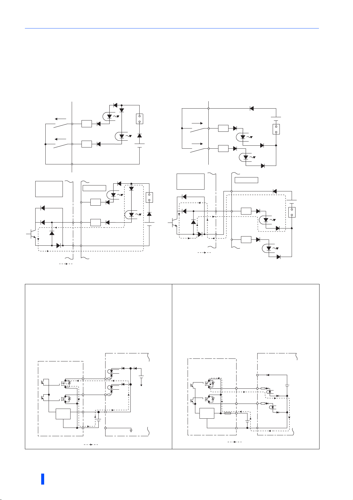
Control circuit specification
Sink logic and source logic
• In the sink logic, a signal switches ON when a current flows from the corresponding signal input terminal.
Terminal SD is common to the contact input signals. Terminal SE is common to the open collector output signals.
• In the source logic, a signal turns ON when a current enters into the corresponding signal input terminal.
Terminal PC is common to the contact input signals. Terminal SE is common to the open collector output signals.
● Current flow concerning the input/output signal
when sink logic is selected
Sink logic
Current
RES
R
SOF
R
SD
Sink
connector
● Current flow concerning the input/output signal
when source logic is selected
Source logic
PC
Current
RES
R
SOF
R
Source
connector
Converter Inverter
Sink
connector
RYB
SE
RES
R
X10
R
SD
Current flow
• When using an external power supply for transistor output
• Sink logic
Use the terminal PC as a common terminal, and perform
wiring as shown below. (Do not connect terminal SD on
the converter with the terminal of 0 V for the external
power supply. When using terminals PC-SD as a 24 VDC
power supply, do not install an external power supply in
parallel with the converter. Doing so may cause a
malfunction in the converter due to undesirable currents.)
Converter
RYB
SE
Current flow
Inverter
PC
X10
RES
R
R
Source
connector
• Source logic
Use the terminal SD as a common terminal, and perform
wiring as follows. (Do not connect terminal PC on the
converter with the terminal of +24 V for the external power
supply. When using terminals PC-SD as a 24 VDC power
supply, do not install an external power supply in parallel
with the converter. Doing so may cause a malfunction in
the converter due to undesirable currents.)
QY40P type transistor
52
Converter
output unit
Constant
voltage
circuit
TB1
TB2
TB17
TB18
24 VDC
RES
SOF
PC
SD
Current flow
INSTALLATION AND WIRING
24 VDC
(SD)
QY80 type transistor
output unit
Constant
voltage
circuit
Fuse
TB1
TB2
TB17
TB18
Current flow
Converter
PC
RES
SOF
24 VDC
SD
24 VDC
(SD)
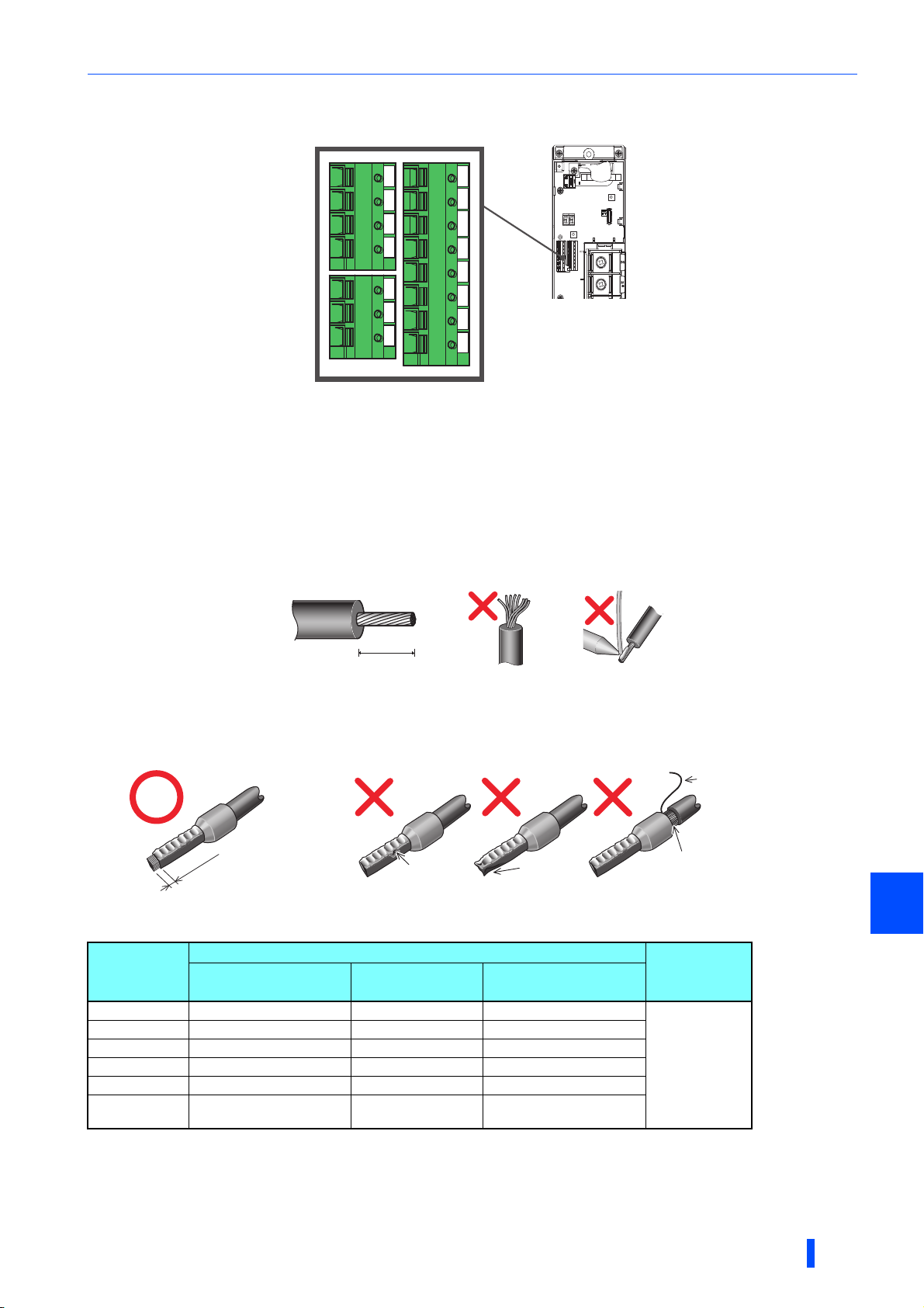
2.7.3 Control circuit terminal layout
10 mm
Cable
Sleeve
0 to 0.5 mm
Control circuit specification
RYB
RSO RYA
SE
A B C
FAN LOH RES
SD
PC
SOF
SD PC
Wiring method
• Wire insertion
Use crimp terminals and stripped wire for the control circuit wiring. For single wire, the stripped wire can be used without crimp terminal.
Connect the end of wires (crimp terminal or stranded wire) to the terminal block.
(1) Strip the signal wires as shown below. If too much of the wire is stripped, a short circuit may occur with neighboring wires.
If not enough of the wire is stripped, wires may become loose and fall out. Twist the stripped end of wires to prevent them
from fraying. Do not solder it.
Wire strip length
(2) Use appropriate crimp terminals (ferrules, blade terminals, etc.).
Insert wires to the crimp terminal, and check that the wires come out for about 0 to 0.5 mm from a sleeve.
Check the condition of the crimp terminals after crimping. Do not use the crimp terminals of which the crimping is
inappropriate, or the face is damaged.
Unstranded wires
Cable
Sleeve
0 to 0.5 mm
Damaged
Crumpled tip
Wires are not inserted into the sleeve.
• Crimp terminals commercially available (as of January 2017)
Phoenix Contact Co., Ltd.
Wire gauge
2
(mm
0.3 AI 0,34-10TQ — —
0.5 AI 0,5-10WH — AI 0,5-10WH-GB
0.75 AI 0,75-10GY A 0, 75-10 AI 0,75-10GY-GB
1 AI 1-10RD A 1-10 AI 1-10RD/1000GB
1.25, 1.5 AI 1,5-10BK A 1,5-10 AI 1,5-10BK/1000GB
0.75 (two-wire
product)
∗1 A ferrule with an insulation sleeve compatible with the MTW wire which has a thick wire insulation.
∗2 Applicable for terminals A, B, and C.
With insulation sleeve
)
AI-TWIN 2×0,75-10GY — —
Ferrule part No.
Without insulation
sleeve
For UL wire∗1
Crimping tool
model No.
CRIMPFOX 6
∗2
2
INSTALLATION AND WIRING
53

Control circuit specification
Flathead screwdriver
Open/close button
Flathead
screwdriver
Open/close button
NICHIFU Co., Ltd.
Wire gauge
(mm2)
0.3 to 0.75 BT 0.75-11 VC 0.75 NH 69
(3) Insert each wire into the terminal.
Blade terminal part
No.
Insulation cap
part No.
When using single wire or stranded wires without a crimp terminal, push the open/
close button all the way down with a flathead screwdriver, and insert the wire.
Crimping tool
model No.
NOTE
• When using stranded wires without a crimp terminal, twist enough to avoid short circuit with neighboring terminals or wires.
• Place the flathead screwdriver vertical to the open/close button. In case the blade tip slips, it may cause the converter
damage or injury.
• Wire removal
Pull the wire while pushing the open/close button all the way down firmly with a flathead screwdriver.
54
INSTALLATION AND WIRING

Control circuit specification
NOTE
• Pulling out the wire forcefully without pushing the open/close button all the way down may damage the terminal block.
• Use a small flathead screwdriver (tip thickness: 0.4 mm / tip width: 2.5 mm).
If a flathead screwdriver with a narrow tip is used, terminal block may be damaged.
Commercially available product (as of January 2017).
Product name Model Manufacturer
Driver
• Place the flathead screwdriver vertical to the open/close button. In case the blade tip slips, it may cause the converter
damage or injury.
SZF
0- 0,4 × 2,5
Phoenix Contact Co., Ltd.
Common terminals of the control circuit (PC, SD, SE)
• Terminals PC, SD, and SE are all common terminals (0 V) for I/O signals and are isolated from each other. Do not earth
(ground) these terminals.
• Terminal SD is a common terminal for the contact input terminals (RES, SOF, and LOH). Use a shielded or twisted cable to
protect the terminal against malfunction caused by external noise. Connect the shielded cable to terminal SD (common
terminal). To connect an external power supply to terminal PC, however, connect the shield of the power supply cable to the
negative side of the external power supply. Do not directly earth (ground) the shield to the enclosure, etc. The open
collector circuit is isolated from the internal control circuit by photocoupler.
• Terminal SE is a common terminal for the open collector output terminals (RYA, RYB, and RSO). The contact input circuit is
isolated from the internal control circuit by photocoupler.
Signal inputs by contactless switches
The contact input terminals of the converter (RES, SOF, and LOH) can be
controlled using a transistor instead of a contact switch as follows.
RES, etc.
Multifunction regeneration
converter
SD
External signal input using transistor
+24 V
2.7.4 Wiring precautions
• It is recommended to use a cable of 0.3 to 1.25 mm2 for the connection to the control circuit terminals.
• The wiring length should be 30 m at the maximum.
However, the wiring length between the control circuit and the box-type reactor should be 5 m at the maximum (refer to
page 64).
• Use shielded or twisted cables for the control circuit terminals and run them away from the main and power circuits
(including the 200 V relay sequence circuit).
• Use two or more parallel micro-signal contacts or twin contacts to prevent a
contact faults when using contact inputs since the control circuit input signals
are micro-currents.
• Always apply a voltage to the fault output terminals (A, B, and C) via a relay
coil, lamp, etc.
Micro signal contacts Twin contacts
2
INSTALLATION AND WIRING
55

Control circuit specification
2.7.5 Details on the control circuit terminals on the
FR-XCB
Power supply for fan
Ter min al
Typ e
symbol
FAN1
Terminal name Terminal function description
Reactor fan power
input
Power input terminal for the fan on the reactor. Connect it to terminal FAN on the converter.
SD
Power supply for fan
Fan power input
common
Output signal
Ter min al
Typ e
Open collector
symbol
LOH1
LOH2
Terminal name Terminal function description Rated specification
Box-type reactor
overheat detection
Box-type reactor
overheat detection
common
Common terminal for terminal FAN1. Connect it to terminal SD on the converter.
Pulses corresponding to the speed of cooling fan on the box-type
reactor is output.
When the sink logic is selected, connect this terminal to terminal
LOH on the converter.
When the source logic is selected, connect this terminal to terminal
PC on the converter.
Common terminal for terminal LOH1.
When the sink logic is selected, connect this terminal to terminal
SD on the converter.
When the source logic is selected, connect this terminal to terminal
LOH on the converter.
Permissible load: 24 VDC
(27 VDC at maximum) 0.1 A
(The voltage drop is 2.8 V at
maximum while the signal is
ON.)
56
INSTALLATION AND WIRING

Wiring
∗1
Never connect the power supply to terminals R/L1, S/L2, and T/L3
on the inverter. Incorrect connection will damage the inverter and the
converter.
∗2
Connect between the inverter terminal P/+ and the converter
terminal P/+ and between the inverter terminal N/- and the converter
terminal N/- for polarity consistency.
Connecting opposite polarity of terminals P/+ an N/- will damage the
converter and the inverter.
∗3
Confirm the correct phase sequence of three-phase current to
connect between the reactor and the converter, and between the
power supply and the converter (terminals R/L1, S/L2, and T/L3).
Incorrect connection will damage the converter.
∗4
Always connect between the power supply and terminals R/L1, S/L2,
and T/L3 of the converter. Operating the inverter without connecting
them will damage the converter.
∗5
Assign the X10 signal to any of the input terminals.
∗6
Do not connect anything to terminal P4.
∗7
To use separate power supply for the control circuit, remove each
jumper at terminal R1/L11 and terminal S1/L21.
∗8
Install the UL listed fuse (refer to
page 179
) on the input side of the
reactor to meet the UL/cUL standards.
∗9
Do not install an MCCB or MC between the reactor and the
converter. Doing so disrupts proper operation.
2.8 Wiring
• Incorrect wiring will cause a fault indication, failure, or damage of the multifunction regeneration converter.
• Refer to the Instruction Manual of each inverter for the wiring of the inverter. Special attention must be paid to the wiring
length and cable size.
2.8.1 Terminal connection diagram
Common bus regeneration mode with harmonic suppression disabled
Inverter
∗1
Power
supply
MCCB
FR-XC
P4
P/+
N/-
RYA
RYB
RSO
SE
Open collector
C
B
A
∗6
Junction terminal
Fuse
Junction terminal
Fuse
Fuse
MC
∗8
Fuse
Fuse
∗8
Fuse
∗8
FR-XCL
R/L1
S/L2
T/L3
∗3∗4
∗3∗9
R2/L12
S2/L22
T2/L32
∗7
R2/L12
S2/L22
T2/L32
R/L1
S/L2
T/L3
R1/L11
S1/L21
RES
SOF
LOH
SD
SOURCE
SINK
PU
connector
R/L1
S/L2
T/L3
R1/L11
S1/L21
P/+Fuse
∗2
N/-
X10(MRS)
RES
SD
Inverter
∗1
R/L1
S/L2
T/L3
R1/L11
S1/L21
P/+
∗2
N/-
∗5
U
V
IM
M
W
U
V
IM
M
W
CAUTION
In the common bus regeneration mode, always connect between the converter terminal RYB and the inverter terminal to which the X10
(MRS) signal is assigned, and also connect between the converter terminal SE and the inverter terminal SD. If the terminals are not
connected, the converter may be damaged.
Junction terminal
INSTALLATION AND WIRING
Fuse
Fuse
X10(MRS)
RES
SD
Inverter
∗1
R/L1
S/L2
T/L3
R1/L11
S1/L21
P/+
∗2
N/-
X10(MRS)
RES
SD
∗5
U
V
IM
M
W
2
∗5
57

Wiring
Power
supply
MCCB
MC
FR-XCL
P4
N/-
FR-XC
R/L1
S/L2
T/L3
RSO
SE
C
B
A
RYB
IM
P/+
R2/L12
S2/L22
T2/L32
P/+
Fuse
R/L1
N/-
Inverter
M
S/L2
T/L3
Fuse
RYA
RES
SD
X10(MRS)
R1/L11
S1/L21
LOH
SD
RES
SOF
PU
connector
Open collector
SINK
SOURCE
∗1
∗1
∗7
∗2∗9
∗3
R1/L11
S1/L21
R2/L12
S2/L22
T2/L32
R/L1
S/L2
T/L3
U
V
W
P1
Earth (ground)
DC reactor
(FR-HEL)∗5
∗6
Fuse
∗8
Fuse
∗8
Fuse
∗8
∗2
MCCB
FR-HAL
∗4
Power regeneration mode
58
∗1 Connect between the inverter terminal P/+ and the converter terminal P4 and between the inverter terminal N/- and the converter terminal
N/- for polarity consistency.
Connecting the opposite polarity of terminals P/+ and N/- will damage the converter and the inverter.
∗2 Confirm the correct phase sequence of three-phase current to connect between the reactor and the converter, and between the power supply
and the reactor.
Incorrect connection will damage the converter.
∗3
Always connect between the power supply and terminals R/L1, S/L2, and T/L3 of the converter. Operating the inverter without connecting them will
damage the converter. A branch point to each of these terminals must be placed between the power supply and the FR-HAL reactor.
∗4 Install the FR-HAL reactor between the node points joined to the converter terminals R/L1, S/L2, and T/L3 and the node points joined to the FR-
XCL reactor. For information to select an appropriate model, refer to page 38.
∗5 To connect a DC reactor, remove a jumper installed across terminals P1 and P/+ before installing the DC reactor.
∗6
To use separate power supply for the control circuit, remove each jumper at terminal R1/L11 and terminal S1/L21.
∗7
For selection of an MCCB for the converter, refer to page 19.
∗8
Install the UL listed fuse (refer to
∗9
Do not install an MCCB or MC between the reactors and the converter. Doing so disrupts proper operation.
INSTALLATION AND WIRING
page 179
) on the input side of the FR-XCL reactor to meet the UL/cUL standards.

Wiring
∗1
Never connect the power supply to terminals R/L1, S/L2, and T/L3 on
the inverter. Incorrect connection will damage the inverter and the
converter.
∗2
Connect between the inverter terminal P/+ and the converter terminal
P/+ and between the inverter terminal N/- and the converter terminal
N/- for polarity consistency.
Connecting opposite polarity of terminals P/+ and N/- will damage the
converter and the inverter.
∗3
Confirm the correct phase sequence of three-phase current to
connect between the reactor and the converter, and between the
power supply and the converter (terminals R/L1, S/L2, and T/L3).
Incorrect connection will damage the converter.
∗4
Always connect between the power supply and terminals R/L1, S/L2,
and T/L3 of the converter. Operating the inverter without connecting
them will damage the converter.
∗5
Assign the X10 signal to any of the input terminals.
∗6
Do not connect anything to terminal P4.
∗7
Install the UL listed fuse (refer to
page 179
) on the input side of the
reactor to meet the UL/cUL standards.
∗8
Do not install an MCCB or MC between the reactor and the converter.
Doing so disrupts proper operation.
Common bus regeneration mode with harmonic suppression enabled
Inverter
∗1
Power
supply
MCCB
FR-XC
P4
P/+
N/-
RYA
RYB
RSO
SE
Open collector
C
B
A
∗6
Junction terminal
Fuse
Junction terminal
Fuse
Fuse
MC
Fuse
∗7
Fuse
∗7
Fuse
∗7
R/L1
S/L2
T/L3
FR-XCB
LOH1
LOH2
FAN1
SD
∗3∗4
∗3∗8
R2/L12
S2/L22
T2/L32
R2/L12
S2/L22
T2/L32
LOH
RES
SOF
SD
PC
FAN
R/L1
S/L2
T/L3
SOURCE
SINK
PU
connector
R/L1
S/L2
T/L3
R1/L11
S1/L21
P/+Fuse
∗2
N/-
X10(MRS)
RES
SD
Inverter
*1
R/L1
S/L2
T/L3
R1/L11
S1/L21
P/+
∗2
N/-
*5
U
V
W
U
V
W
IM
IM
M
M
CAUTION
In the common bus regeneration mode, always connect between the converter terminal RYB and the inverter terminal to which the X10
(MRS) signal is assigned, and also connect between the converter terminal SE and the inverter terminal SD. If the terminals are not
connected, the converter may be damaged.
NOTE
• The control logic (sink logic/source logic) of the converter and the inverter must be matched. The converter does not operate
properly if the control logic is not consistent with each other.
(Refer to page 51 for the switching of the control logic. Refer to the Instruction Manual of the inverter for the switching of the
control logic of the inverter.)
• Keep the wiring length between terminals as short as possible.
• When the power is distorted or falls off sharply, the reactors may generate abnormal acoustic noise. This acoustic noise is
caused by the power supply fault and not by the damage of the converter.
Junction terminal
INSTALLATION AND WIRING
Fuse
Fuse
X10(MRS)
RES
SD
Inverter
∗1
R/L1
S/L2
T/L3
R1/L11
S1/L21
P/+
∗2
N/-
X10(MRS)
RES
SD
∗5
U
V
IM
M
W
∗5
2
59

Wiring
Total wiring length
10 m or shorter
∗1 Installation of a fuse on each cable is recommended to prevent the damage
from spreading in case of an inverter failure. Select the fuse according to the
motor capacity. To use a motor whose capacity is smaller than the inverter
capacity by two ranks or more, select the fuse with the capacity that is one
rank lower than the inverter capacity. Refer to the fuse selection table on page
21.
For connection of multiple inverters, use the same gauge cable as the
inverter's power cable for wiring between the inverter main circuit terminal (P/+
or N/-) and a junction terminal. (Refer to the Instruction Manual of the inverter.)
∗2 The function needs to be assigned to an inverter terminal to be connected to
the converter terminal RYB.
Refer to the Instruction Manual of the Inverter.
∗3 Do not install any MCCB between the inverter and the converter (P to P and N
to N).
For the gauge of the cable used for connection of multiple inverters, refer to
page 67.
Control circuit cable gauge
0.3 to 1.25 mm
2
Control circuit wiring length
30 m
Main circuit wiring length
5 m
2.8.2 Wiring (common bus regeneration mode with
harmonic suppression disabled)
Wiring between the power supply and the reactor
• Cable gauge differs by the capacity. Select an appropriate cable by referring to page 43 to perform wiring.
Dedicated reactor
R/L1
S/L2
T/L3
R2/L12
S2/L22
T2/L32
Power
supply
MCCB
MC
Wiring between the reactor and the converter
• Cable gauge differs by the capacity. Select an appropriate cable by referring to page 43 to perform wiring.
Dedicated reactor
(FR-XCL)
R/L1
S/L2
T/L3
R2/L12
S2/L22
T3/L32
Multifunction regeneration
converter
R2/L12
S2/L22
T3/L32
P/+
N/-
Wiring between the converter and the inverter
• Connect the wiring for the control circuit correctly so that the commands sent from the converter are transmitted to the
inverter without fail.
For the cable gauge of the cable for the main circuit terminals P/+ and N/- (P to P and N to N), refer to page 43.
Multifunction regeneration
converter
R2/L12
S2/L22
T2/L32
Control
circuit
P/+
N/-
RYB
RSO
SE
NOTE
• Terminals P/+ and N/- are used for connection with the inverter. Do not connect anything to power input terminals (R/L1, S/L2,
and T/L3) of the inverter. Incorrect power input connection will damage the inverter. Connecting opposite polarity of terminals
P/+ and N/- will damage the inverter and the converter.
• Do not connect a DC reactor to the inverter when using the converter in the common bus regeneration mode.
60
INSTALLATION AND WIRING
∗1
Inverter
P/+
∗3
N/-
X10 (MRS)
RES
SD
∗2

Wiring between the power supply and the converter
Cable gauge
1.25 mm
2
Total wiring length
10 m or shorter
Cable gauge
0.75 to 2 mm
2
Supply power to the power detecting terminals (R/L1, S/L2, and T/L3) separately from the main circuit wiring.
Wiring
Multifunctionregeneration
R2/L12
S2/L22
T2/L32
R/L1
S/L2
T/L3
R1/L11
S1/L21
Jumper
converter
Power
supply
Dedicated reactor
R/L1
S/L2
T/L3
NOTE
• The terminals R/L1, S/L2, and T/L3 on the converter are control terminals to detect power phases of the power supply. For
wiring, the voltage phase must be consistent between terminals R2/L12, S2/L22, and T2/L32 and terminals R/L1, S/L2, and
T/L3. If these terminals are not connected correctly, the converter does not operate properly.
• If the inverter is operated while the converter terminals R/L1, S/L2, and T/L3 are not connected to the power supply, the
converter will be damaged.
Wiring of the power supply and the inverter (equipped with terminals R1/
L11 and S1/L21)
For the power input to the control circuit in the inverter which has the control circuit power supply terminals (R1/L11 and S1/
L21), bypass the converter and perform the direct wiring between the inverter (these terminals) and the power supply.
MCCB
Power
supply
Power for inverter
control circuit
R1/L11
S1/L21
NOTE
• Remove jumpers across main circuit terminals R/L1 and R1/L11 and across S/L2 and S1/L21 on the inverter (refer to the
Instruction Manual of the inverter).
• Always connect the power supply to terminals R1/L11 and S1/L21 of the inverter directly to supply power to the control circuit.
If they are not connected, the inverter may shut off its output by a fault occurrence or be damaged.
2
INSTALLATION AND WIRING
61

Wiring
Total wiring length
10 m or shorter
∗1 Installation of a fuse on each cable is recommended to prevent the damage from
spreading in case of an inverter failure. Select the fuse according to the motor capacity.
To use a motor whose capacity is smaller than the inverter capacity by two ranks or
more, select the fuse with the capacity that is one rank lower than the inverter capacity.
Refer to the fuse selection table on page 21.
∗2 Do not install any MCCB between the inverter and the converter (P to P and N to N).
Main circuit wiring length
5 m or shorter
2.8.3 Wiring (power regeneration mode)
Wiring between the power supply and the reactor
• Cable gauge differs by the capacity. Select an appropriate cable by referring to page 43 to perform wiring.
AC reactor
R/L1
S/L2
T/L3
(FR-HAL)
To inverter
Power
supply
MCCB
∗1
MC
∗1
MCCB
∗2
∗1 Select a MCCB and a MC according to the inverter capacity.
∗2 For selection of MCCB for the converter, refer to page 19.
Dedicated reactor
(FR-XCL)
R/L1
S/L2
T/L3
R2/L12
S2/L22
T2/L32
Wiring between the reactor and the converter
• Cable gauge differs by the capacity. Select an appropriate cable by referring to page 43 to perform wiring.
Dedicated reactor
(FR-XCL)
R/L1
S/L2
T/L3
R2/L12
S2/L22
T3/L32
Multifunction regeneration
converter
R2/L12
S2/L22
T3/L32
P/+
N/-
Wiring between the converter and the inverter
• For the cable gauge of the cable for the main circuit terminals P/+ and N/- (P to P and N to N), refer to page 43.
Inverter
R/L1
S/L2
Multifunction regeneration
converter
R2/L12
S2/L22
T2/L32
P4
P/+
N/-
T/L3
∗1
P/+
∗2
N/-
NOTE
• Connecting opposite polarity of terminals P4 and N/- will damage the converter.
62
INSTALLATION AND WIRING

Wiring between the power supply and the converter
Cable gauge
1.25 mm
2
Total wiring length
10 m or shorter
Supply power to the power detecting terminals (R/L1, S/L2, and T/L3) separately from the main circuit wiring.
AC reactor
(FR-HAL)
MCCB
X
Y
Z
To the inverter
Dedicatedreactor
(FR-XCL)
R/L1
S/L2
T/L3
R2/L12
S2/L22
T2/L32
Jumper
FR-XC
R2/L12
S2/L22
T2/L32
R/L1
S/L2
T/L3
R1/L11
S1/L21
Power
supply
R
S
T
Wiring
NOTE
• The terminals R/L1, S/L2, and T/L3 on the converter are control terminals to detect power phases of the power supply. For
wiring, the voltage phase must be consistent between terminals R2/L12, S2/L22, and T2/L32 and terminals R/L1, S/L2, and
T/L3. If these terminals are not connected correctly, the converter does not operate properly.
• If the inverter is operated while the converter terminals R/L1, S/L2, and T/L3 are not connected to the power supply, the
converter will be damaged.
2
INSTALLATION AND WIRING
63
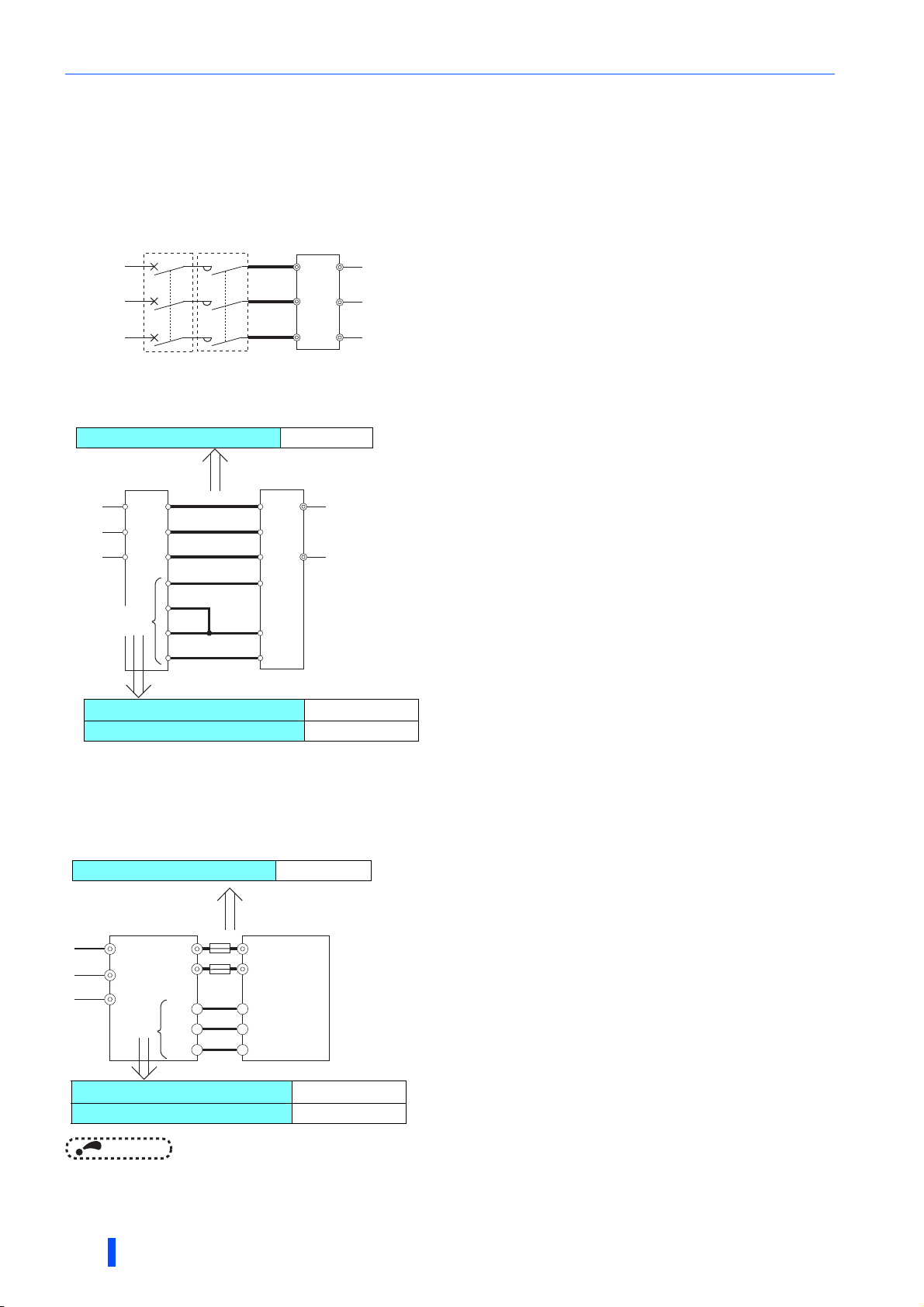
Wiring
Main circuit wiring length
10 m or shorter
Control circuit cable gauge
0.3 to 1.25 mm
2
Control circuit wiring length
5 m or shorter
∗1 Installation of a fuse on each cable is recommended to prevent the damage from
spreading in case of an inverter failure. Select the fuse according to the motor capacity.
To use a motor whose capacity is smaller than the inverter capacity by two ranks or
more, select the fuse with the capacity that is one rank lower than the inverter capacity.
Refer to the fuse selection table on page 21.
For connection of multiple inverters, use the same gauge cable as the inverter's power
cable for wiring between the inverter main circuit terminal (P/+ or N/-) and a junction
terminal. (Refer to the Instruction Manual of the inverter.)
∗2 The function needs to be assigned to an inverter terminal to be connected to the
converter terminal RYB.
Refer to the Instruction Manual of the Inverter.
∗3 Do not install any MCCB between the inverter and the converter (P to P and N to N).
For the gauge of the cable used for connection of multiple inverters, refer to page 67.
Control circuit cable gauge
0.3 to 1.25 mm
2
Control circuit wiring length
30 m
Main circuit wiring length
50 m or shorter
2.8.4 Wiring (common bus regeneration mode with
harmonic suppression enabled)
Wiring between the power supply and the reactor
• Cable gauge differs by the capacity. Select an appropriate cable by referring to page 43 to perform wiring.
MCCB
MC
Dedicated reactor
R/L1
R2/L12
Power
supply
S/L2
T/L3
S2/L22
T2/L32
Wiring between the reactor and the converter
• Cable gauge differs by the capacity. Select an appropriate cable by referring to page 43 to perform wiring.
Multifunction
R2/L12
S2/L22
T3/L32
LOH
SD
FAN
regeneration
converter
P/+
N/-
Dedicated reactor
R/L1
S/L2
T/L3
Control
circuit
R2/L12
S2/L22
T3/L32
LOH1
LOH2
SD
FAN1
Wiring between the converter and the inverter
• Connect the wiring for the control circuit correctly so that the commands sent from the converter are transmitted to the
inverter without fail.
For the cable gauge of the cable for the main circuit terminals P/+ and N/- (P to P and N to N), refer to page 43.
Multifunction regeneration
converter
R2/L12
S2/L22
T2/L32
Control
circuit
P/+
N/-
RYB
RSO
SE
NOTE
• Terminals P/+ and N/- are used for connection with the inverter. Do not connect anything to power input terminals (R/L1, S/L2,
and T/L3) of the inverter. Incorrect power input connection will damage the inverter. Connecting opposite polarity of terminals
P/+ and N/- will damage the inverter and the converter.
• Do not connect an AC or DC reactor to the inverter when using the converter in the common bus regeneration mode.
64
INSTALLATION AND WIRING
∗1
Inverter
P/+
∗3
N/-
X10 (MRS)
RES
SD
∗2

Wiring between the power supply and the converter
Cable gauge
1.25 mm
2
Total wiring length
10 m or shorter
Cable gauge
0.75 to 2 mm
2
Supply power to the power detecting terminals (R/L1, S/L2, and T/L3) separately from the main circuit wiring.
Wiring
Multifunctionregeneration
R2/L12
S2/L22
T2/L32
R/L1
S/L2
T/L3
R1/L11
S1/L21
Jumper
converter
Power
supply
Dedicated reactor
R/L1
S/L2
T/L3
NOTE
• The terminals R/L1, S/L2, and T/L3 on the converter are control terminals to detect power phases of the power supply. For
wiring, the voltage phase must be consistent between terminals R2/L12, S2/L22, and T2/L32 and terminals R/L1, S/L2, and
T/L3. If these terminals are not connected correctly, the converter does not operate properly.
• If the inverter is operated while the converter terminals R/L1, S/L2, and T/L3 are not connected to the power supply, the
converter will be damaged.
Wiring of the power supply and the inverter (equipped with terminals R1/
L11 and S1/L21)
For the power input to the control circuit in the inverter which has the control circuit power supply terminals (R1/L11 and S1/
L21), bypass the converter and perform the direct wiring between the inverter (these terminals) and the power supply.
MCCB
Power
supply
Power for inverter
control circuit
R1/L11
S1/L21
NOTE
• Remove jumpers across main circuit terminals R/L1 and R1/L11 and across S/L2 and S1/L21 on the inverter (refer to the
Instruction Manual of the inverter).
• Always connect the power supply to terminals R1/L11 and S1/L21 of the inverter directly to supply power to the control circuit.
If they are not connected, the inverter may shut off its output by a fault occurrence or be damaged.
2.8.5 When using separate power supplies for the
control circuit and the main circuit
When the protection circuit is activated, opening of the electromagnetic contactor
(MC) on the input side of the converter results in power loss in the control circuit of
the converter, disabling the fault output signal retention. To retain the fault signal,
add the node points joined to the control circuit power supply terminals R1/L11 and
S1/L21 on the MC power cable. Do not connect the power cable to incorrect
terminals. Doing so may damage the converter.
MCCB
Multifunction
regeneration converter
R/L1
S/L2
T/L3
R1/L11
S1/L21
2
Remove the jumper.
INSTALLATION AND WIRING
65

Earthing (Grounding) precautions
2.9 Earthing (Grounding) precautions
• Always earth (ground) the multifunction regeneration converter and the dedicated reactor FR-XCL or FR-XCB.
Purpose of earthing (grounding)
Generally, an electrical apparatus has an earth (ground) terminal, which must be connected to the ground before use.
An electrical circuit is usually insulated by an insulating material and encased. However, it is impossible to manufacture an
insulating material that can shut off a leakage current completely, and actually, a slight current flows into the case. The
purpose of earthing (grounding) the case of an electrical apparatus is to prevent operators from getting an electric shock from
this leakage current when touching it.
To avoid the influence of external noises, the earthing (grounding) is important to EMI-sensitive equipment that handle low-
level signals or operate very fast such as audio equipment, sensors, computers.
Earthing (grounding) system to be established
As described previously, the purpose of earthing (grounding) is roughly classified into the electrical shock prevention and the
prevention of malfunction due to the influence of electromagnetic noise. These two purposes should be clearly distinguished.
Leakage currents containing many high frequency components flow into the earthing (grounding) cables of the converter.
When any other devices (EMI-sensitive devices) are earthed (grounded) nearby, the appropriate earth (ground) system must
be established as follows to prevent malfunction of such EMI-sensitive devices due to the leakage current from the converter,
inverter, or reactor.
• Make the separate earth (ground) connection (I) for the converter, inverter, and reactor away from other EMI-sensitive
devices wherever possible.
Establishing adequate common (single-point) earth (ground) system (II) shown in the following figure is allowed only in
cases where the separate earth (ground) system (I) is not feasible. Do not make inadequate common (single-point) earth
(ground) connection (III).
In a high building, it may be effective to use its iron structure frames as earthing (grounding) electrode for EMI prevention in
order to separate from the earth (ground) system for electric shock prevention.
• Earthing (Grounding) must conform to the requirements of national and local safety regulations and electrical codes (NEC
section 250, IEC 61140 class 1 and other applicable standards).
• Use the thickest possible earthing (grounding) cable. The size of the earthing (grounding) cable should be the same or
larger than the one indicated in the table on page 43.
• The earthing (grounding) point should be as close as possible to the converter, and the earth (ground) cable length should
be as short as possible.
• Run the earthing (grounding) cable as far away as possible from the I/O wiring of the EMI-sensitive devices, and run them
in parallel in the minimum distance.
High frequency
products
(converter, etc.)
(I) Separate earthing (grounding): Good
EMI-sensitive
devices
High frequency
products
(converter, etc.)
(II) Common (single-point)
earthing (grounding): OK
EMI-sensitive
devices
High frequency
products
(converter, etc.)
(III) Inadequate common (single-point)
earthing (grounding): Bad
EMI-sensitive
devices
Earthing (grounding) of the FR-XCL reactor
• The FR-XCL reactor is usually earthed (grounded) by being mounted securely on a panel of the enclosure. If it is not well
earthed (grounded) by being mounted on a panel of the enclosure, remove varnish from a mounting hole and make an
earthing (grounding) connection from the hole.
(For the location of the mounting hole whose varnish should be removed, refer to the outline dimensions on page 165.)
• For earthing (grounding) of the reactor, use the same gauge earthing (grounding) cable as that for the converter (refer to
page 43).
66
INSTALLATION AND WIRING

Connection of the converter and the multiple inverters
Example of earthing (grounding)
Power
supply
(a)
Dedicated reactor
box-type reactor
(b)
or
FR-XC series
converter
(c)
(d)
Inverter
Motor
M
(e)
: Earthing (grounding) cable
Symbol
a
b
c
d
e
Make the separate earth (ground) connection for the converter, inverter, and reactor wherever possible.
The earthing (grounding) cable should be as close as possible to the power cables, and all these cables should be in
parallel.
The converter and the dedicated reactor are allowed to have the common (single-point) earth (ground) system (unless the
reactor is earthed (grounded) by being mounted on a panel of the enclosure).
If the inverter and the converter are installed far apart and the main circuit cables between them (P to P and N to N) are too
long to store in an enclosure, the inverter earthing (grounding) cable is allowed to be connected to the converter and run
as close as possible to the main circuit cables in parallel.
When the main circuit cables are short enough to store in an enclosure, the inverter is allowed to join in the common
(single-point) earth (ground) connection (c).
The motor earthing (grounding) cable is allowed be connected to the inverter earth (ground) terminal.
Description
2.10 Connection of the converter and the
multiple inverters
2.10.1 Connection in common bus regeneration mode
When the multifunction regeneration converter is used in common bus regeneration mode, multiple inverters can be
connected to the converter. (The allowable number or permissible total capacity of inverters to be connected differs according
to the converter capacity and the harmonic suppression function condition. Refer to page 156.) Select the converter so that
the total capacity of the connected inverters must not exceed the applicable inverter capacity.
• For the multiple inverter connection, place the higher capacity inverter in the lower number axis.
• Junction terminals and cross wiring may be required for the wiring of the multiple inverters. For the gauge of cable used
between the two junction terminals, refer to the descriptions in the following figure. Total capacity of higher-number axis
inverters must be considered for the cable selection.
• It is recommended to install a fuse on each inverter power cable used between the inverter and the junction terminal, as
shown in the following figure. Select a fuse according to the motor capacity. (Refer to page 19.)
When using a motor whose capacity is smaller than the inverter capacity by two ranks or more, select the fuse with the
capacity that is one rank lower than the inverter capacity.
• Keep the wiring length (total length of cables) of each main circuit terminal (P/+ or N/-) between the converter and each
inverter within 5 m or less when converter's harmonic suppression function is disabled or within 50 m or less when the
function is enabled.
• The total wiring length between terminals P/+ or terminals N/- on the converter and connected inverters should not exceed
the length shown in the following table.
2
Harmonic suppression enabled Harmonic suppression disabled
50 m 5 m
INSTALLATION AND WIRING
67

Connection of the converter and the multiple inverters
Wiring examples
In the following examples, six inverters (two FR-A820-00167(2.2K) inverters, two FR-A820-00105(1.5K) inverters, and two
FR-A820-00077(0.75K) inverters) are connected to the FR-XC-11K converter.
• Main circuit wiring example
FR-XC
-11K
P/+
N/-
a
c
e
g
i
k
Junction terminal 1
Fuse
b
Junction terminal 2
d
Junction terminal 3
f
Junction terminal 4
h
Junction terminal 5
j
Junction terminal 6
1st inverter
P/+
2.2 kW
FR-A820
-00167
N/-
(2.2K)
2nd inverter
P/+
2.2 kW
FR-A820
-00167
N/-
(2.2K)
3rd inverter
P/+
1.5 kW
FR-A820
-00105
N/-
(1.5K)
4th inverter
P/+
1.5 kW
FR-A820
-00105
N/-
(1.5K)
5th inverter
P/+
0.75 kW
FR-A820
-00077
N/-
(0.75K)
6th inverter
P/+
l
N/-
FR-A820
-00077
(0.75K)
0.75 kW
1st inverter
a: The gauge of cable between the FR-XC and the junction terminal 1 is 14 mm because
Motor
the FR-XC capacity is 11 kW.
b: The gauge of cable between the junction terminal 1 and the 1st axis inverter is 2 mm
because the inverter capacity is 2.2 kW.
2nd inverter
c: The gauge of cable between the junction terminal 1 and the junction terminal 2 is
2
14 mm because the total capacity of lower axis inverters is regarded as 7.5 kW (an
Motor
approximate inverter capacity of "6.7 kW" determined by the expression: 2.2 + 1.5 +
1.5 + 0.75 + 0.75).
d: The gauge of cable between the junction terminal 2 and the 2nd axis inverter is 2 mm
because the inverter capacity is 2.2 kW.
3rd inverter
e: The gauge of cable between the junction terminal 2 and the junction terminal 3 is
Motor
5.5 mm because the total capacity of lower axis inverters is regarded as 5.5 kW (an
approximate inverter capacity of "4.5 kW" determined by the expression: 1.5 + 1.5 +
0.75 + 0.75).
f: The gauge of cable between the junction terminal 3 and the 3rd axis inverter is 2 mm
because the inverter capacity is 1.5 kW.
4th inverter
g: The gauge of cable between the junction terminal 3 and the junction terminal 4 is
3.5 mm because the total capacity of lower axis inverters is regarded as 3.7 kW (an
Motor
approximate inverter capacity of "3.0 kW" determined by the expression: 1.5 + 0.75 +
0.75).
h: The gauge of cable between the junction terminal 4 and the 4th axis inverter is 2 mm
because the inverter capacity is 1.5 kW.
5th inverter
i: The gauge of cable between the junction terminal 4 and the junction terminal 5 is
Motor
2 mm because the total capacity of lower axis inverters is 1.5 kW determined by the
expression: 0.75 + 0.75.
j: The gauge of cable between the junction terminal 5 and the 5th axis inverter is 2 mm
because the inverter capacity is 0.75K.
6th inverter
k: The gauge of cable between the junction terminal 5 and the junction terminal 6 is 2 mm
Motor
because the inverter capacity is 0.75K.
l: The gauge of cable between the junction terminal 6 and the 6th axis inverter is 2 mm
because the inverter capacity is 0.75K.
2
2
2
2
2
2
2
2
2
2
2
68
INSTALLATION AND WIRING

• Control circuit wiring example
• For the control circuit wiring, use shielded or twisted wires, and
separate the wire from the main circuit and high-voltage circuits.
• Keep the length of cables between the converter and the final axis
inverter on each terminal within 30 m.
FR-XC
1st inverter
X10RYB
RESRSO
FR-A820
-00167
(2.2K)
SDSE
2nd inverter
X10
RES
FR-A820
-00167
(2.2K)
SD
3rd inverter
X10
RES
FR-A820
-00105
(1.5K)
SD
Connection of the converter and the multiple inverters
4th inverter
X10
RES
FR-A820
-00105
(1.5K)
SD
5th inverter
X10
RES
FR-A820
-00077
(0.75K)
SD
6th inverter
X10
RES
FR-A820
-00077
(0.75K)
SD
2
INSTALLATION AND WIRING
69

PU installation on converter
2.11 PU installation on converter
• When the PU (inverter operation panel or optional parameter unit) is installed on the multifunction regeneration converter,
the setting of converter parameters is possible by using the PU.
Use the option FR-CB2[ ] or the following connector and cable available on the market.
(To install the operation panel, the optional connector (FR-ADP) is also required.)
Securely insert one end of connection cable into the PU connector on the converter and the other end into the connection
connector on the parameter unit or the FR-ADP attached on the operation panel along the guides until the stoppers are
fixed.
Parameter unit connection cable
(FR-CB2[ ]) (option)
Parameter Unit
(FR-PU07) (option)
Operation panel of
the inverter (FR-DU08)
Operation panel connection
connector (FR-ADP) (option)
NOTE
• Refer to the following table when fabricating the cable on the user side. Keep the total cable length within 20 m.
Commercially available products (as of February 2015)
Name Model Manufacturer
Communication cable
RJ-45 connector 5-554720-3 Tyco Electronics
SGLPEV-T (Cat5e/300 m)
24AWG × 4P
Mitsubishi Cable Industries, Ltd.
70
INSTALLATION AND WIRING

Communication operation
2.12 Communication operation
Using the PU connector enables communication operation from a personal computer, etc. When the PU connector is used for
connection between the converter and a personal, FA, or other computer with a communication cable, a user program can run
to monitor the converter or read and write parameters.
Communication with the Mitsubishi inverter protocol (computer link operation) can be performed.
(For the details, refer to page 103.)
CC-Link communication can also be performed when a communication option (FR-A8NC) is installed on the converter.
Installation of the FR-A8NC
• To install the FR-A8NC, the enclosed earthing (grounding) cable is required. Follow this procedure to install the FR-A8NC.
Step Description
1 Insert spacers into the mounting holes that will not be tightened with the option mounting screws.
2 Fit the connector on the FR-A8NC to the guide of the connector on the converter, and insert it as far as it goes.
Secure the one terminal of earthing (grounding) cable to the left top mounting hole on the converter with the mounting screw of the
3
FR-A8NC (tightening torque: 0.33 to 0.40 N·m).
Fix the right top side part of the FR-A8NC securely to the converter with the mounting screw of the FR-A8NC. Place another
terminal of the earthing (grounding) cable on the left bottom mounting hole in the FR-A8NC, and secure the cable terminal and the
4
FR-A8NC to the converter with the mounting screw of the FR-A8NC (tightening torque: 0.33 to 0.40 N·m). If the screw holes do not
line up, the connector may not be inserted deep enough. Check the connector.
Earthing
(grounding)
cable
NOTE
Fixing screw
Fixing screw
Earthing (grounding)
Option connector
Spacer
Earthing (grounding) cable
• When the FR-A8NC is installed, it is difficult to check the operation status 7-segment LED display on the converter.
• Affix the communication option LED label on the control
circuit terminal block cover so that small holes in the label
can be aligned with the communication operation status
inspection ports on the cover.
cable
Spacer
Fixing screw
Fixing screw
Fixing screw
Fixing screw
Spacer
2
• Lead the CC-Link cable to the outside of the converter through the side of the
control circuit terminal block cover. Use a nipper or the like to cut the side of
the control circuit terminal block cover. Finish the cut surface without leaving
rough edges.
INSTALLATION AND WIRING
Communication option LED label
71
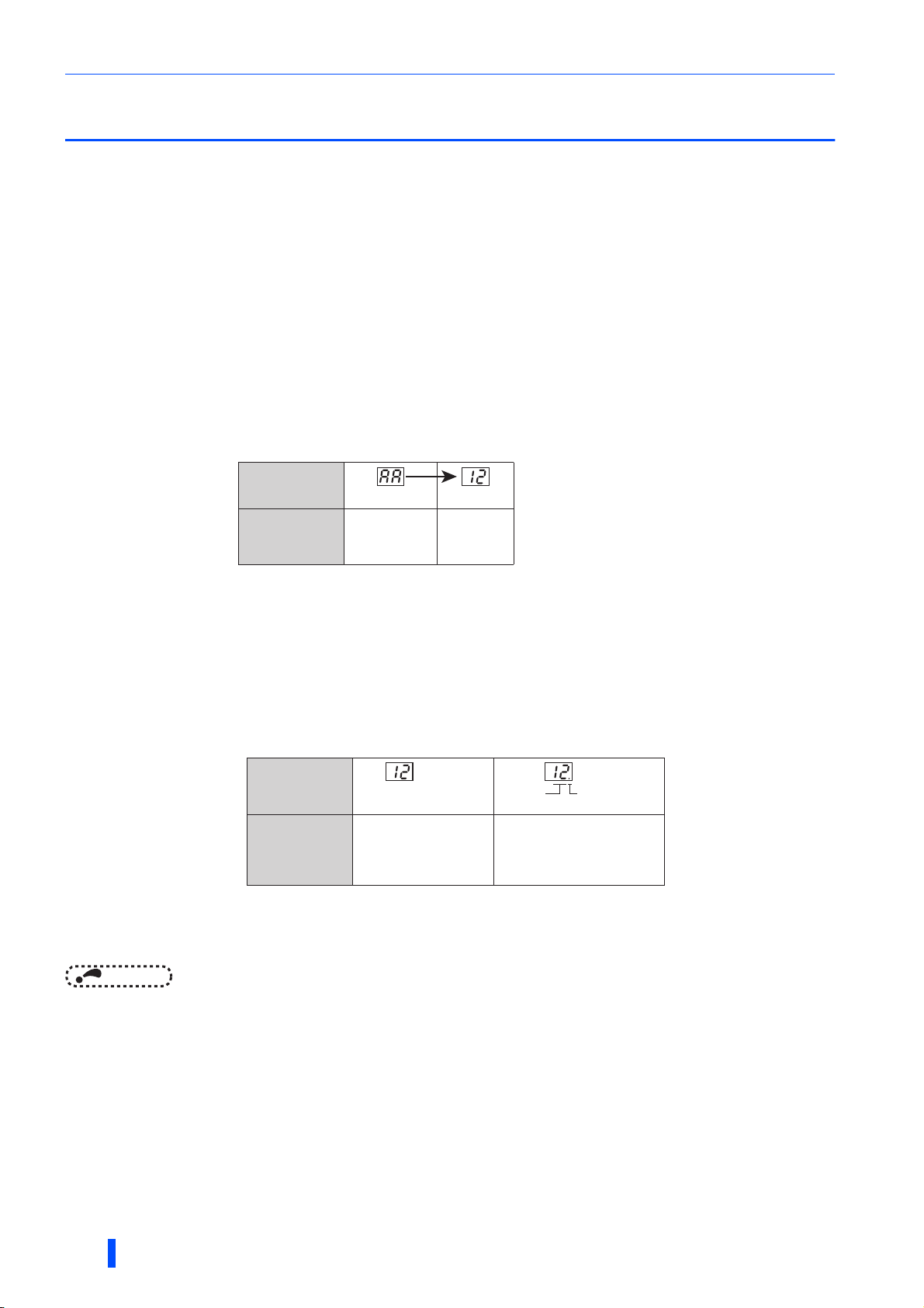
Before powering and starting operation
2.13 Before powering and starting operation
2.13.1 Installation
Check the following points before powering and starting operation of the converter.
Make sure that the converter is installed in a proper location and manner. (Refer to page 29.)
• Confirmation of wiring
Make sure that wiring of the main circuit and the control circuit is proper.
Make sure that the installed option and peripheral devices are appropriate and the wiring of them is proper. (Refer to page
57.)
2.13.2 Powering
When the charge lamp and the operation status 7-segment LED display turn ON properly after powering the converter, the
converter is ready.
The operation status LED display shows the following after powering the converter.
LED display
indication
Converter status
∗ An example of the indications of power value.
During initialization
after power-on
Normal
(ready for
power driving)
*
2.13.3 Operation
Turn ON the start signal of the inverter. The motor starts acceleration until its speed is constant. All this while, the operation
status LED display keeps displaying input power value (power driving).
Turn OFF the start signal of the inverter. The motor starts deceleration to a stop. The converter operation status changes
according to the amount of regenerative power. During regenerative driving, the regenerative drive indication (a decimal point
LED) is ON as shown below.
LED display
indication
Converter status
Input power value
is displayed as a percent.
During power driving. During regenerative driving.
∗1
Input
∗2
power value
The regenerative drive
indication (a decimal point LED)
is ON during operation.
∗1 An example of the indications of power value.
∗2 A rate of input power compared against the
rated capacity is displayed in 10% increments.
For example, the indication "12" displayed in
the LED indicator corresponds to 120%.
Regenerative
drive indication
∗2
72
NOTE
• It is not a fault if noise comes from the dedicated reactor during regenerative driving of the converter (in other words, it is a
fault if noise comes despite the stop state of the converter by the Converter stop (SOF) signal).
• If needed, devise methods of reducing noise by modifying the enclosure in which the reactor is installed.
INSTALLATION AND WIRING

Digital characters and their corresponding printed equivalents
Printed Digital
Printed Digital
Printed Digital
2.14 Digital characters and their corresponding
printed equivalents
Digital characters displayed on the 7-segment LED display are as follows.
0
1
2
3
4
5
6
7
8
9
A
B
C
D
E
F
G
H
I
J
K
L
M
N
O
o
P
Q
S
T
U
V
W
r
R
-
INSTALLATION AND WIRING
2
73

MEMO
74

3 PARAMETERS
Thischapterexplainstheparametersinthisproduct.
Alwaysreadtheinstructionsbeforeuse.
3.1 Operation panel (FR-DU08) ......................................................76
3.2 Monitoring the converter status ..............................................79
3.3 Parameter unit (FR-PU07) / Parameter unit with battery
pack (FR-PU07BB(-L)) ..............................................................80
3.4 Parameter list ............................................................................84
3.5 Parameter details ......................................................................86
PARAMETERS
3
75

Operation panel (FR-DU08)
3.1 Operation panel (FR-DU08)
3.1.1 Components of the operation panel
Installing the inverter operation panel (FR-DU08) on the multifunction regeneration converter allows to set the converter
parameters and monitor the converter status.
(a) (b) (c)
(d)
(e)
(f)
(j)
(g)
(k)
(l)
(m)
(h)
(i)
No. Component Name Description
(a)
(b)
(c)
(d)
(e)
(f)
(g)
(h)
Not available for the FR-XC(-PWM) converter.
Operation panel mode
LED indicator
Not available for the FR-XC(-PWM) converter.
Not available for the FR-XC(-PWM) converter.
Monitor (5-digit LED)
Not available for the FR-XC(-PWM) converter.
FWD key, REV key
STOP/RESET key
MON: ON when the operation panel is in the monitor mode. Quickly blinks twice
intermittently while the converter protective function is activated.
PRM: ON when the operation panel is in the parameter setting mode.
Shows a numeric value, a parameter number, etc.
(The monitor item can be changed according to the Pr.52 setting.)
FWD key: Its LED is ON during power driving.
REV key: Its LED is ON during regenerative driving.
The LEDs are OFF when the converter stops its operation due to power supply failure or
when a fault occurs.
The LEDs blink when the converter stops its operation due to a cause except the abovementioned cause.
Used to stop operation commands.
Used to reset the converter when the protective function is activated.
76
(i)
(j)
(k)
(l)
(m)
Setting dial
MODE key
SET key
ESC key
PU/EXT key
PARAMETERS
Turn the setting dial to select a parameter or change the parameter setting.
Press the setting dial to display a fault history number in the fault history mode.
Switches the operation panel to a different mode.
Holding this key for 2 seconds locks the operation of the operation panel.
Used to confirm each selection.
Pressing this key during the converter
operation changes the monitor item to be
displayed.
(The monitor item can be changed according to the Pr.52 setting.)
Goes back to the previous display.
Holding down this key changes the mode of operation panel back to the monitor mode.
Cancels the PU stop warning.
Initial setting in the monitor mode
Input current
Input voltage
Bus voltage

Operation panel (FR-DU08)
3.1.2 Basic operation of the operation panel (factory
setting)
Monitor
First screen (Input current∗1 monitoring)
(First priority monitor screen)
Parameter setting
Parameter clear All parameter clear Fault history clear
Second screen
(Input voltage
Value change
(Example) (Example) (Example)
Blinking Blinking Blinking
∗1 monitoring)
The present setting
displayed.
Parameter write is complete.
Third screen
(Bus voltage∗1 monitoring)
(Example)
Alternating
Parameter copy
Initial value change list
Fault record 1∗2 Fault record 2∗2 Fault record 8∗2
Fault history
Hold down
∗1 The monitor item can be changed. (Refer to page 95.)
∗2 For the details of fault history, refer to page 143.
The last eight fault records can be displayed.
(On the display of the last fault record (fault record 1), a decimal point LED is ON.)
When the fault history is empty, is displayed.
Parameter setting mode
In the parameter setting mode, converter functions (parameters) can be set.
The following table explains the indications in the parameter setting mode.
Operation panel
indication
Function name Description
Parameter setting mode The set value of the displayed parameter number is read or changed. 78
Parameter clear
All parameter clear
Fault history clear Deletes the fault history. 143
Parameter copy
Initial value change list Identifies the parameters that have been changed from their initial settings. 129
Clears and resets parameter settings to the initial values.
However, terminal function selection parameters are not cleared.
For the details of the uncleared parameters, refer to page 175.
Clears and resets parameter settings to the initial values. Terminal function
selection parameters are also cleared.
For the details of the uncleared parameters, refer to page 175.
Copies the parameter settings saved in the converter to the operation panel.
The parameters copied to the operation panel can be also copied to other
converter.
Refer
to page
126
126
127
3
PARAMETERS
77

Operation panel (FR-DU08)
3.1.3 Digital characters and their corresponding
printed equivalents
Digital characters displayed on the operation panel display are as follows.
0
E(e)1F(f)2G(g)3H4h
R r S(s) T(t) U u V v W w X(x) Y(y) Z(z)Q(q)
5 6 7 8 9 A B(b) C c D(d)
I(i) J(j) K(k) L(l)
M(m)
N n O o P(p)
3.1.4 Changing the parameter setting value
Changing example Change the setting of Pr.52 PU main monitor selection.
Operating procedure
TurningONthepoweroftheconverter
1.
The operation panel is in the monitor mode.
Selectingtheparametersettingmode
2.
Press to choose the parameter setting mode. (The parameter number read previously appears.)
Selectingtheparameter
3.
Turn until " " (Pr.52) appears. Press to read the present set value. " " (initial value)
appears.
Changingthesettingvalue
Turn to change the set value to " ". Press to confirm the selection. " " and " " are
displayed alternately.
4.
NOTE
• If a parameter write condition is not satisfied, a parameter write error appears on the LCD display. (Refer to page 134.)
POINTPOINT
• When Pr.77 Parameter write selection = "2 (initial value)", the parameter setting change is always enabled.
The parameter setting change can be disabled by changing the Pr.77 setting. (Refer to page 101.)
• Turn to read another parameter.
• Press to show the setting again.
• Press twice to show the next parameter.
• Press twice to return to the monitor mode.
Error indication Description
Write disable error
78
PARAMETERS
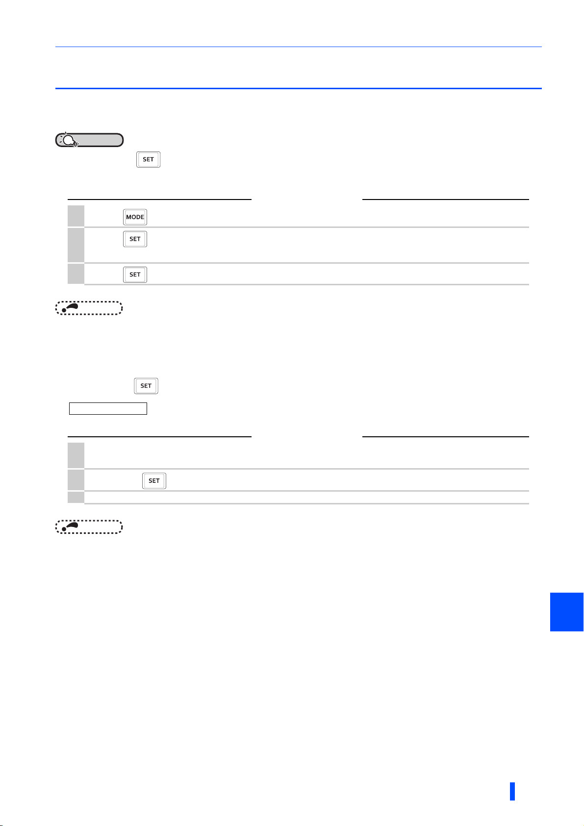
Monitoring the converter status
3.2 Monitoring the converter status
3.2.1 Monitoring of input voltage or bus voltage
POINTPOINT
• Press on the operation panel in the monitor mode to switch the monitor item between input current, input
voltage, and bus voltage (factory setting).
Operating procedure
1.
Press during converter operation to monitor the input current. The unit of current "A" appears.
Press to monitor the input voltage. This operation is valid under any operation mode of the converter
2.
and whether the converter is running or at a stop. The unit of voltage "V" appears.
3.
Press to monitor the bus voltage. The unit of voltage "V" appears.
NOTE
•Use Pr.52 PU main monitor selection to change the monitor item. (Refer to page 95.)
3.2.2 First priority monitor screen
The first priority monitor screen, which is displayed first when the operation panel becomes in the monitor mode, is selectable.
To set it, hold down when the desired monitor item is displayed on a monitor screen.
Changing example Set the monitor screen displaying the input voltage as the first priority monitor screen.
Operating procedure
Change the mode of the operation panel to the monitor mode, and switch the monitor screen to the one on
1.
which the input voltage can be monitored.
2.
Hold down for 1 second. The input voltage monitor screen is set as the first priority monitor screen.
3. When the operation panel is in the monitor mode next time, the input voltage monitored value is displayed first.
NOTE
•Use Pr.52 PU main monitor selection to change the monitor item. (Refer to page 95.)
3
PARAMETERS
79

Parameter unit (FR-PU07) / Parameter unit with battery pack (FR-PU07BB(-L))
3.3 Parameter unit (FR-PU07) / Parameter unit
with battery pack (FR-PU07BB(-L))
Installing the optional parameter unit (FR-PU07) / parameter unit with battery pack (FR-PU07BB(-L)∗1) on the multifunction
regeneration converter allows to set the converter parameters and monitor the converter status. However, the available
functions in the parameter unit installed on the converter are limited compared to those in the parameter unit installed on the
inverter.
3.3.1 Components of the parameter unit
∗1 Batteries are not included in FR-PU07BB-L.
POWER lamp
ON when the power is turned ON.
I In
10.0A
STF FWD PU
Monitor
● Liquid crystal display
(16 characters × 4 lines, with backlight)
● Monitoring (current, voltage, etc.)
I In
10.0A
STF FWD PU
POWER lamp
ON when the power is turned ON.
Battery indicator
The lamp color turns to
orange from green when the
battery is low.
Monitor
● Liquid crystal display
(16 characters × 4 lines, with backlight)
● Monitoring (current, voltage, etc.)
ALARM lamp
ON when a converter fault
occurs.
FR-PU07
Operation keys
FR-PU07BB(-L)
Key Description
Used for parameter setting.
Press this key to select the parameter setting mode.
Used to display the first priority monitoring screen.
The first priority monitoring screen is initially set to the input current monitoring screen.
Used to cancel the operation.
Used to display the function menu.
A variety of functions can be used from the function menu.
Used to shift to the next item in the setting or monitoring mode.
to
/
Used to enter a parameter number or set value.
Used to clear the PU stop warning (" " indication on the converter) when the converter is stopped by pressing (by
the PU stop function).
Not available for the FR-XC(-PWM) converter.
• Press either of these keys on the parameter setting mode screen to change the parameter setting value sequentially.
• On the selecting screen, these keys are used to move the cursor.
• Hold down and press either of these keys to advance or return the display screen one page.
ALARM lamp
ON when a converter
fault occurs.
Operation keys
80
Not available for the FR-XC(-PWM) converter.
Not available for the FR-XC(-PWM) converter.
• Stop command key.
• Used to reset the converter when a fault occurs.
• Used to write a set value in the setting mode.
• Used as a clear command key for All parameter clear or the alarm clear (resetting the fault history).
• Used to enter a decimal point when entering numerical value.
• Used as a parameter number read key in the parameter setting mode.
• Used as an item select key on the menu screen such as parameter list or monitoring list.
• Used to show the details of each fault in the alarm (fault) history mode.
NOTE
• Do not operate the keys with sharp tools.
• Do not press the LCD part.
PARAMETERS

Parameter unit (FR-PU07) / Parameter unit with battery pack (FR-PU07BB(-L))
3.3.2 Monitoring function
Indications displayed on the monitoring screen
I In
(a) Main monitor
(b) Phase sequence
indication
(a) Main monitor
The input current, input voltage, bus voltage, alarm history, or other monitor data is displayed.
Press to display the monitoring list.
Select an item from the monitoring list and press to monitor the selected item.
The following items can be monitored.
I In: Input current (A)
V In: Input voltage (V)
Dc Bus: Bus voltage (V)
Alarm His: Fault history (the last 8 faults)
Hz In: Power supply frequency (Hz)
THT %: Electronic thermal O/L relay load factor (%)
Pwr In: Input power (kW)
Cum Pwr: Cumulative power (kW)
Cum Opr: Cumulative energization time (h)
I/P Signal: Input signal
O/P Signal: Output signal
(b) Connection phase sequence indication
The following phase sequence is displayed.
STF: Positive
STR: Negative
---: Power supply not detected
(c) Operating status indication
The operating status of the multifunction regeneration converter is displayed.
STOP: Stop state
FWD: Power driving
REV: Regenerative driving
ALAR: Fault state
(d) Operation mode indication
"EXT" (External operation mode) is always indicated.
(e) Unit indication
The unit of the main monitor item is indicated.
(f) Warning indication
The following is indicated when the multifunction regeneration converter outputs a warning.
Nothing is indicated when there is no warning output.
(For the details, refer to page 134.)
OL: Overload signal detection
TH: Electronic thermal relay function pre-alarm
PS: PU stop
MT: Maintenance signal output
SL: Power supply not detected
10.0
STF FWD EXT
(c) Operating status
indication
OL
A
(f) Warning indication
(e) Unit indication
(d) Operation mode
indication
3
PARAMETERS
81

Parameter unit (FR-PU07) / Parameter unit with battery pack (FR-PU07BB(-L))
3.3.3 Function menu
Press in any operation mode to call the function menu, on which you can perform various functions.
NOTE
• There are menus in which some functions are not available.
Function menu list
Function menu Description
1. MONITOR
2. PU Oper The menu appears, but every function in the menu is disabled.
3. Pr.List
4. Pr.Clear
5. Alarm Hist The last 8 faults are displayed.
6. AlarmClear The fault history (all fault records) can be cleared.
7. Inv.Reset
8. T/Shooting The menu appears, but every function in the menu is disabled.
9. S/W The software control number of the converter is displayed.
10. Selectop
11. Option The option connector occupancy condition is displayed.
12. FRCpy set Parameter copy (reading, writing, and verifying of parameters) can be performed.
∗1 Parameter copy using the FR-PU07(BB) is available when the product manufactured in September 2015 or later is used.
The monitoring list appears, and the functions on monitoring such as the monitor item selection
to be displayed, the first priority monitoring screen selection.
The parameter menu appears, and the parameter setting and the displaying of the initial value
change list are available.
The menu to clear parameters appears. Parameter clear and All parameter clear can be
executed.
The multifunction regeneration converter can be reset. (The inverter can also be reset
simultaneously.)
The signals assigned to the I/O control terminals and the ON/OFF status of the signals can be
checked.
∗1
Function menu transition
key
1 MONITOR
2 PU Oper
3
4
5
6
7
8
9
10
11
12
1 I In
2 V In
3 Dc Bus
4 Alarm His
5 Hz In
6 THT %
7 Pwr In
8
Cum Pwr
9
Cum Opr
10
11
12
13
14
I/P Signal
15
16
O/P Signal
Not available for the FR-XC(-PWM) converter.
Input current (A)
Input voltage (V)
Bus voltage (V)
Fault history (the last 8 faults)
Power supply frequency (Hz)
Electronic thermal O/L relay load factor (%)
Input power (kW)
Cumulative power (kW)
Cumulative energization time (h)
Empty (no function)
Empty (no function)
Empty (no function)
Empty (no function)
Empty (no function)
Input signal∗1
Output signal∗2
∗1 Monitoring of input signal status
The terminal names displayed correspond to the
converter's terminals as shown below.
□STF
□RL
□RM
□RH
□JOG
□FU
□ABC1
□ABC2
□MRS
□
□RES
□CS
□STR
□AU
□RT
∗2 Monitoring of output signal status
The terminal names displayed correspond to the
converter's terminals as shown below.
□RUN
□SU
□IPF
□OL
□RH
: Terminal LOH
□MRS
STOP
: Terminal SOF
□RES
: Terminal RES
The displayed names other
than above do not have any functions.
□RUN
: Terminal RYB
□SU
: Terminal RSO
□IPF
: Terminal RYA
□ABC2
: Terminal ABC
The displayed names other
than above do not have any functions.
82
PARAMETERS
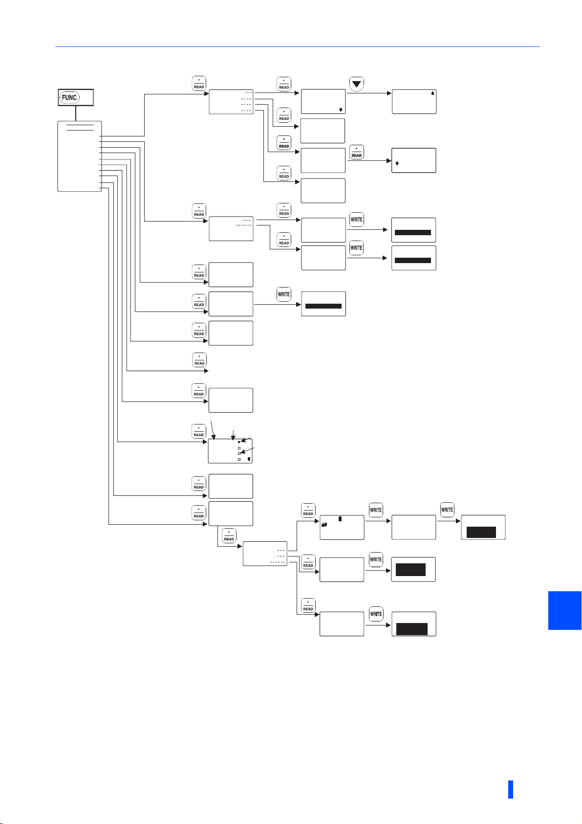
Parameter unit (FR-PU07) / Parameter unit with battery pack (FR-PU07BB(-L))
Complet ed
Complet ed
Complet ed
0
Reading
Completed
Writing
Completed
Verifying
Completed
key
1
2
3 Pr.List
4 Pr.Clear
5 Alarm His
6 AlarmClear
7 INV.Reset
8 T/Shooting
9 S/W
10 Selectop
11 Option
12 PRCpy set
3 Pr.List
4 Pr.Clear
5 Alarm His
6 AlarmClear
7 INV.Reset
8 T/Shooting
1 Setting Mode
2 Pr.List
3 Set Pr.List
4 Def.Pr.List
1 1 Clear Pr.
2 Clear All
1 OHT
5 OV2
2 PUE
6 UVT
3 OV2
4 OV2
ALARM CLEAR
Exec<WRITE>
Cancel<ESC>
INV.RESET
Exec<WRITE>
Cancel<ESC>
Not available for the FR-XC(-PWM) converter.
Fault indications.
7 UVT
The last eight faults are listed.
8 UVT
An indication "INV.RESET" appears, but this is the function to reset the multifunction regeneration converter.
SETTING MODE
0〜9:Ser Pr.No.
Select Oper
⇒
0 Pr Mode
1 Max.F
2 Min.F
3 ROH Sel
SET Pr.LIST
⇒
12 RYA S
65 Retry
75 RES Mode
DEF.Pr.LIST
0 Pr Mo 0
⇒
1 Max.F 60.00
2 Min.F 50.00
Clear Pr.
Exec<WRITE>
Cancel<ESC>
Clear All Pr.
Exec<WRITE>
Cancel<ESC>
ALARM CLEAR
Completed
1 Appl.Grp
2
Pr.List
3 User List
4 Param Copy
Perform parameter copy (writing) while the
∗1
∗1
SOF signal is ON.
99
3
17
36 Fan Oper
0
0, 1
Clear Pr.
Clear All Pr.
Completed
Completed
9 S/W
Terminal name∗2
10 Selectop
11 Option
12 PRCpy set
∗3
The function availability varies
depending on the software version
of the parameter unit.
∗4 Only the copy area 1 is available to
store a parameter setting of the
FR-XC series converter. Do not use
the copy area 2 for any other product
to preserve the converter parameter
setting stored in the copy area 1.
Doing so will delete the converter
parameter setting stored in the copy
area 1.
*3
<S/W>
INV:〇〇〇〇
RL
RM
RH
RT
<option>
OP1: A8NC
OP2: --- OP3: ----
1 Copy area 1
2 Copy area 2
3 Copy area 3
∗5
A
The values set in Pr.3 to
Pr.16 are displayed.
ON
0
:
:
:
:
Perform parameter copy
(writing) while the SOF signal
is ON.
1
2
3
OFF
∗4
Copy area 1
1 Read VFD
2 Write VFD
3 Verifing
An indication "INV" (inverter) appears, but the software version of the multifunction regeneration converter is displayed.
The terminal names displayed correspond to the converter's terminals as shown below.
∗2
RH: Terminal LOH
MRS:
Terminal SOF
RES:
Terminal RES
"- - - " means that no corresponding function is assigned to the terminal
(the corresponding parameter in Pr.3 to Pr.16 = "9999") or that the terminal does not have a function.
∗5
RUN:
SU:
IPF: Terminal RYA
ABC2:
Name:
00
:Select Char
READ:Decide Char
WRITE:DecideName
000
Area 1 to VFD
WRITE:Executing
ESC:Cancel
000
Verify Area 1
WRITE:Executing
ESC:Cancel
Terminal RYB
Terminal RSO
Terminal ABC
000
Overwrite area 1
WRITE:Executing
ESC:Cancel
Param Copy
Writing
Completed
Please Reset
Param Copy
Verifying
Completed
Param Copy
Reading
Completed
3
83
PARAMETERS

Parameter list
3.4 Parameter list
Parameter read/write requires the operation panel (FR-DU08) or the optional parameter unit (FR-PU07 or FR-
PU07BB(-L)).
NOTE
• indicates simple mode parameters.
• The setting of parameters in highly colored cell ( ) is changeable during operation even if "1" (write disabled) is set to
Pr.77 Parameter write selection.
Pr. Name Setting range
0
1
2
3
4
7
8
9
11
12
16
22∗4
23∗4
31
32
33
34
35
44
46
47
48
52
57
58
59
61
65
67
68
69
Simplemodeselection
Maximumpowersupply
frequency
Minimumpowersupply
frequency
LOHterminalfunction
selection
SOFterminalfunction
selection
RESterminalfunction
selection
SOFinputselection
OHinputselection
RSOterminalfunction
selection
RYAterminalfunction
selection
ABCterminalfunction
selection
Currentlimitlevel
Currentlimitlevel
(regenerative)
Lifealarmstatusdisplay
Inrushcurrentlimitcircuitlife
display
Controlcircuitcapacitorlife
display
Maintenancetimer
Maintenancetimerwarning
outputsettime
Instantaneouspowerfailure
detectionsignalclear
Watt-hourmeterclear
Energizationtimecarrying-
overtimes
Cumulativepowermonitor
digitshiftedtimes
PUmainmonitorselection
Restartselection
Freeparameter1
Freeparameter2
Keylockoperationselection
Retryselection
Numberofretriesatfault
occurrence
Retrywaitingtime
Retrycountdisplayerase
0, 9999 0 0 86
60 Hz (Read only) — (60 Hz) 86
50 Hz (Read only) — (50 Hz) 86
0, 3 to 5, 9999
0 to 2 1 0 88
0, 1 1 0 88
0 to 4, 6 to 11, 14 to 18, 98,
99, 101 to 104,106 to 111,
114 to 118, 198, 199, 9999
0 to 190% 0.1% 150 90
0 to 190%, 9999 0.1% 9999 90
0, 1, 4, 5, 8, 9, 12, 13 (Read
only)
0 to 100% (Read only) 1% 100% 91
0 to 100% (Read only) 1% 100% 91
0 (1 to 9998) 1 0 92
0 to 9998, 9999 1 9999 92
0, 9999 1 9999 93
0, 10, 9999 1 9999 95
Read only 1 0 95
0 to 4, 9999 1 9999 95
0, 5 to 10, 25, 28 1 0 95
0, 9999 1 9999 97
0 to 9999 1 9999 97
0 to 9999 1 9999 97
0, 10 1 0 97
0 to 4 1 0 98
0 to 10, 101 to 110,
1001 to 1010, 1101 to 1110
0.1 to 600 s 0.1 s 1 s 98
0 1 0 98
Minimum
setting
Initial value
increment
1587
1 0 87
1387
1 1 89
1089
1 99 89
1091
1 0 98
Refer to
page
Customer
setting
84
PARAMETERS

Parameter list
Pr. Name Setting range
75
77
80∗4
81∗4
82∗4
83∗4
117
118
119
120
121
123
124
145
Resetselection/
disconnectedPUdetection/
PUstopselection
Parameterwriteselection
Voltagecontrolproportional
gain
Voltagecontrolintegralgain
Currentcontrolproportional
gain
Currentcontrolintegralgain
PUcommunicationstation
number
PUcommunicationspeed
PUcommunicationstopbit
length
PUcommunicationparity
check
PUcommunicationretry
count
PUcommunicationwaiting
timesetting
PUcommunicationCR/LF
selection
PUdisplaylanguage
selection
0 to 3, 14 to 17 1 14 100
1, 2 1 2 101
0 to 1000% 1% 100 90
0 to 1000% 1% 100 90
0 to 200% 1% 100 102
0 to 200% 1% 100 102
0 to 31 1 0 104
48, 96, 192, 384 1 192 104
0, 1, 10, 11 1 1 104
0 to 2 1 2 104
0 to 10, 9999 1 1 104
0 to 150 ms, 9999 1 ms 9999 104
0 to 2 1 1 104
0 to 7 1 0 125
168
169
Parameterformanufacturersetting.Donotset.
269
342
415
416
500∗1
501∗1
502∗1
520
542∗1, ∗2,∗3
543∗1, ∗2,∗3
544∗1,∗2
896
989
990
991
Pr.CLR
ALL.C
Err.CL
Pr.CPY
∗1 The setting is available only when a communication option (FR-A8NC) is installed.
∗2 The setting is applied after the converter reset or next power-ON.
∗3 [L.ERR] LED indicator on the FR-A8NC blinks when a setting is changed. The setting is applied after the converter reset, and the [L.ERR] turns
∗4 The setting is available only when the harmonic suppression is enabled.
CommunicationEEPROM
writeselection
SW2settingstatus
Controlmethodselection
Communicationerror
executionwaitingtime
Communicationerror
occurrencecountdisplay
Stopmodeselectionat
communicationerror
Parameterformanufacturersetting.Donotset.
Stationnumber(CC-Link)
Transmissionspeed
selection(CC-Link)
CC-Linkextendedsetting
Powerunitcost
Parameterformanufacturersetting.Donotset.
PUbuzzercontrol
PUcontrastadjustment
Parameterclear
Allparameterclear
Faulthistoryclear
Parametercopy
OFF.
0, 1 1 0 124
0 to 15 (Read only) 1 15 94
0, 1, 9999 1 9999 40
0 to 999.8 s 0.1 s 0 s 123
0 1 0 123
0, 3 1 0 123
1 to 64 1 1 117
0 to 4 1 0 117
0, 1, 12 1 0 117
0 to 500 0.01 0 96
0, 1 1 1 125
0 to 63 1 58 125
(0), 1 1 0 126
(0), 1 1 0 126
(0), 1 1 0 143
(0), 1 to 3 1 0 127
Minimum
setting
increment
Initial value
Refer to
page
Customer
setting
Pr.
list
3
PARAMETERS
85
Parameter details
3.5 Parameter details
3.5.1 Showing/hiding extended parameters (Pr.0)
This function restricts the parameters that are read on the PU (operation panel or parameter unit).
Pr. Name Initial value Setting range Description
9999
0 Simple mode selection
• When Pr.0 = "9999", only the simple mode parameters are displayed on the PU. (For the simple mode parameters, refer to
the parameter list on page 84.)
• In the initial setting (Pr.0 = "0"), simple mode parameters and extended parameters are displayed.
0
0
NOTE
• Every parameter can be read through communication regardless of the
•
Pr.991 PU contrast adjustment
is regarded as a simple mode parameter on the FR-PU07.
Pr.0
3.5.2 Power frequency input to the converter (Pr.1 and
Displays only the simple mode
parameters.
Displays simple mode and extended
parameters.
setting when a communication option is installed.
Pr.2)
The following parameters show that the allowable power frequency for the converter is between 50 and 60 Hz.
Pr. Name Initial value Setting range Description
1
2
Maximum power supply
frequency
Minimum power supply
frequency
60 Hz (60 Hz)
50 Hz (50 Hz)
The parameter shows that the upper limit
of allowable range of the power
frequency is 60 Hz.
(Read only)
The parameter shows that the lower limit
of allowable range of the power
frequency is 50 Hz.
(Read only)
86
PARAMETERS
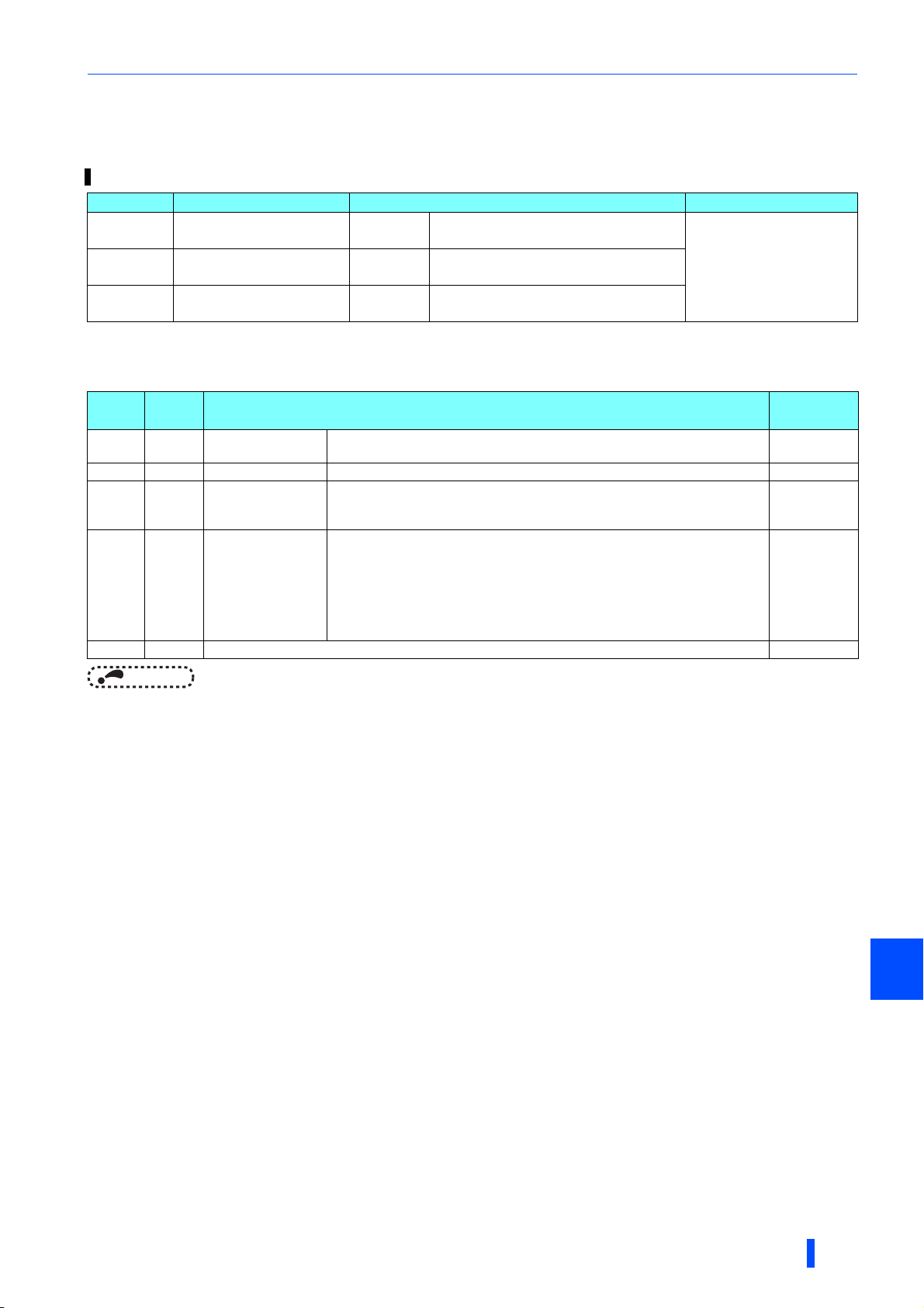
Parameter details
3.5.3 Input terminal function selection (Pr.3, Pr.4, and
Pr.7)
Use the following parameters to select or change the input terminal functions.
Pr. Name Initial value (signal name) Setting range
3
4
7
LOH terminal function
selection
SOF terminal function
selection
RES terminal function
selection
Input terminal function assignment
• Use Pr.3, Pr.4, and Pr.7 to assign the functions of the input terminals. Refer to the following table to set the parameters.
5 LOH (Box-type reactor overheat protection)
0 SOF (Converter stop)
3 RES (Converter reset)
0, 3 to 5, 9999
Setting
9999 — No function —
Signal
name
0 SOF Converter stop
3 RES Converter reset When this signal turns ON, the converter reset is performed. —
4OH
5LOH
External thermal
relay input
Box-type reactor
overheat protection
When this signal turns ON, the converter operation stops.
The converter operation for this signal can be changed by using Pr.8.
The signal is input from the external thermal relay. When this signal turns ON,
the fault E.H occurs and the converter output is shut off.
The converter operation for this signal can be changed by using Pr.9.
The signal is input from the box-type reactor. If the converter with harmonic
suppression function enabled starts operation while the LOH signal is not
assigned to any of the input terminals or if the cooling fan in the box-type
reactor connected the converter stops due to a failure or reduces speed, the
fault E.FT1 occurs and the converter output is shut off. If the LOH signal is input
to the converter with harmonic suppression function disabled, the fault E.FT1
occurs and the converter output is shut off.
Function
NOTE
• One function can be assigned to the different terminals. In this case, the logic of terminal input is OR.
• When the terminal assignment is changed by changing the initial setting of Pr.3, Pr.4, and Pr.7 (Input terminal function
selection), it may cause improper wiring due to a mismatch between the terminal name and the signal name or affect other
functions. Set parameters after confirming the function of each terminal.
Related
parameter
Pr.8
Pr.9
—
PARAMETERS
3
87
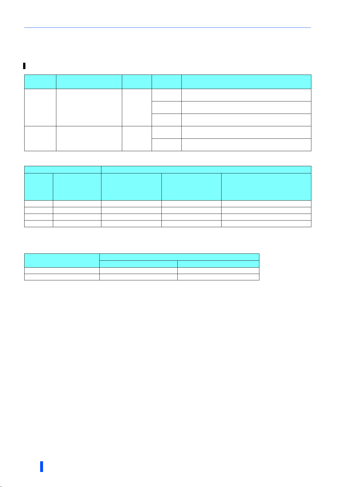
Parameter details
3.5.4 Operation selection for the SOF signal and the
OH signal (Pr.8 and Pr.9)
The converter operations can be changed by using Pr.8 for the SOF signal and Pr.9 for the OH signal.
Pr. Name
8 SOF input selection
9 OH input selection
Initial
value
0
0
Setting
range
0
1
2
0
1
Description
NO contact: Turning ON of the SOF signal stops the
converter operation.
NC contact: Turning OFF of the SOF signal stops the
converter operation.
External signal: NC contact
CC-Link communication: NO contact
NO contact: Turning ON of the OH signal stops the converter
operation after a fault occurs.
NC contact: Turning OFF of the OH signal stops the
converter operation after a fault occurs.
<Converter operation determined by the SOF signal input status and the Pr.8 setting>
SOF signal input status Converter operation
External
terminal
OFF OFF Operation continues. Operation stops. Operation stops.
OFF ON Operation stops. Operation stops. Operation stops.
ON OFF Operation stops. Operation stops. Operation continues.
ON ON Operation stops. Operation continues. Operation stops.
Virtual terminal
of CC-Link
communication
∗1 The converter with the FR-A8NC not installed does not operate when Pr.8 = "1" (NC contact). To use the external terminal with NC contact
specification without using CC-Link communication, set Pr.8 = "2" (External signal: NC contact, CC-Link communication: NO contact).
Pr.8 = "0"
(NO contact)
Pr.8 = "1"
(NC contact)
(External terminal: NC contact,
∗1
virtual terminal on CC-Link
communication: NO contact)
<Converter operation determined by the OH signal input status and the Pr.9 setting>
Pr.8 = "2"
OH signal input status
(external terminal)
ON Operation stops due to the fault. Operation continues.
OFF Operation continues. Operation stops due to the fault.
Converter operation
Pr.9 = "0" Pr.9 = "1"
88
PARAMETERS

Parameter details
3.5.5 Output terminal function selection (Pr.11, Pr.12,
and Pr.16)
Use the following parameters to change the functions of the open collector output terminals and relay output terminals.
Pr. Name
11
12
16
RSO terminal
function selection
RYA terminal
function selection
ABC terminal
function selection
Ter min al
type
Open
collector
output
terminal
Relay
output
terminal
Initial value (signal name) Setting range
1 RSO (During converter reset)
0 RDY (Inverter run enable)
99 ALM (Fault output)
0 to 4, 6 to 11, 14 to 18, 98,
99, 101 to 104, 106 to 111,
114 to 118, 198, 199, 9999
Output signal list
• Functions listed below can be assigned to any of the output terminal.
• Refer to the following table to set the parameters. (0 to 99: Positive logic, 101 to 199: Negative logic)
Setting
Positive
Negative
logic
logic
0 — RDY Inverter run enable Output when the inverter is ready.
1 101 RSO During converter reset Output during a converter reset.
2 102 CVO Converter running
3 103 OL Overload warning Output when the current limit function is active. Pr.22, Pr.23
4104PHS
6106IPF
7107Y7
8108THP
9 109 FAN Fan fault output Output when a fan fault occurs. —
10 110 FIN
11 111 RTY During retry Output during retry processing.
14 114 Y14 Life alarm
15 115 Y15 Maintenance timer alarm
16 116 Y16
17 117 PS PU stopped Output while the PU is stopped.
18 118 FTP
98 198 LF Alarm
99 199 ALM Fault
9999 — No function
Signal
name
Power supply phase
detection
Instantaneous power failure
detection
Regenerative drive
recognition
Electronic thermal O/L relay
pre-alarm
Heatsink overheat prealarm
Instantaneous power failure
detection hold
Box-type reactor overheat
pre-alarm
Function
Output when the converter is regenerative driving,
or when the converter with harmonic suppression
enabled is running.
Output when a phase is confirmed after a completion of
the power supply phase detection.
Output when an instantaneous power failure is
detected.
Output during regenerative driving.
Output when the electronic thermal relay cumulative
value reaches 85% of the transistor protection thermal
activation level. (The Converter overload trip (electronic
thermal relay function) fault (E.C) occurs when the
value reaches 100%.)
Output when the heatsink temperature reaches about
85% of the heatsink overheat protection operation
temperature.
Output when any of the control circuit capacitor, the
inrush current limit circuit, or the cooling fan
approaches the end of its life.
Output when the cumulative operation time reaches the
set time period.
Output when the IPF signal turns ON. This signal keeps
being output until a converter reset is performed or
Pr.44 is set to "0."
Outputs when the speed of cooling fan in the box-type
reactor decreases.
Output when an alarm (fan fault or communication error
warning) occurs.
Output when the converter's protective function
activates to stop the output (at fault occurrence).
parameter
Pr.57
Pr.65, Pr.67
to Pr.69
Pr.31 to
Pr.33
Pr.34, Pr.35
Pr.44
Pr.36, Pr.121
Related
Refer
to
page
90
97
98
91
92
93
105
3
PARAMETERS
89

Parameter details
3.5.6 DC voltage control (Pr.22, Pr.23, Pr.80, and Pr.81)
Use the following parameters to control DC voltage output from the converter with harmonic suppression enabled as
commanded.
Operation can be stable enough with these parameters in the initial setting, however, some adjustments may be
required if voltage vibration occurs depending on the power supply condition.
Pr. Name
22 Current limit level
23
80
81 Voltage control integral gain
Current limit level
(regenerative)
Voltage control proportional
gain
Initial
value
150% 0 to 190%
9999
100% 0 to 1000%
100% 0 to 1000%
Setting
range
Set the current limit where the current limit
operation starts (during power driving).
0 to 190%
9999 The same setting in Pr.22 is applied.
Set the current limit where the current limit
operation starts (during regenerative driving).
Set the proportional gain for the voltage control.
Increasing the setting value reduces the DC
voltage fluctuation caused by external
disturbance.
Set the integral gain for the voltage control.
Increasing the setting value shortens the recovery
time from the DC voltage fluctuation caused by
external disturbance.
Description
Adjusting DC voltage fluctuation (Pr.80 and Pr.81)
• Adjust the fluctuation range of the DC voltage by setting Pr.80.
Increasing the setting value reduces the DC voltage fluctuation caused by external disturbance.
• Adjust the recovery time to the commanded value at a fluctuation of DC voltage by setting Pr.81.
Increasing the setting value shortens the recovery time from the DC voltage fluctuation caused by external disturbance.
NOTE
• Setting Pr.80 too large makes the operation unstable.
• Setting only Pr.81 makes the operation unstable.
Setting the current limit level (Pr.22 and Pr.23)
• Limit the output current not to exceed the specified value.
Set the current limit level by using Pr.22.
Current limit level at the regenerative operation can be individually set by setting a value other than "9999" to Pr.23
Set the current limits as a percentage (set current limit ratios) with 100 being equal to the converter rated current in Pr.22
and Pr.23.
• The OL signal is output when output currents are limited by the current limit level (when the current limit function is active).
NOTE
• When the output current reaches the current limit level, DC voltage decreases during power driving or increases during
regeneration.
90
PARAMETERS

Parameter details
0 0 0 0 0 0 0 0 0 0 0 0 0 0 0
bit 0: Control circuit
capacitor life
1
15bit 7 0
bit 2: Cooling fan life
bit 3: Inrush current limit circuit life
● Read the
Pr.31 setting.
● The Pr.31 setting "1"
(Decimal number converted from
binary data is shown.)
(the control circuit capacitor
life has reached the life
alarm output level) is shown.
3.5.7 Converter parts life display (Pr.31 to Pr.33)
The degrees of deterioration of main circuit capacitor, cooling fan and inrush current limit circuit can be diagnosed on
the monitor.
When a part approaches the end of its life, an alarm can be output by self diagnosis to prevent a fault.
(Note that the life diagnosis of this function should be used as a guideline only, because with the exception of the main
circuit capacitor, the life values are theoretical calculations.)
Pr. Name
31 Life alarm status display
32
33
Inrush current limit circuit life
display
Control circuit capacitor life
display
Initial
value
0
100% (0 to 100%)
100% (0 to 100%)
Setting
range
(0, 1, 4, 5, 8, 9,
12, 13)
Description
Displays whether or not the parts of the control
circuit capacitor, cooling fan, and inrush current
limit circuit have reached the life alarm output
level. Read-only.
Displays the deterioration degree of the inrush
current limit circuit. Read-only.
Displays the deterioration degree of the control
circuit capacitor. Read-only.
Life alarm display and signal output (Y14 signal, Pr.31)
• Whether or not the parts of the control circuit capacitor, cooling fan or inrush current limit circuit have reached the life alarm
output level can be checked with Pr.31 Life alarm status display and the life alarm (Y14) signal.
Pr.31
(decimal)
13 1101
12 1100 ×
91001 ×
81000 ××
50101 ×
40100 × ×
10001 ××
00000 ×××
(binary)
• The Life alarm (Y14) signal turns ON when any of the control circuit capacitor, cooling fan and inrush current limit circuit
reaches the life alarm output level.
• For the terminal used for the Y14 signal, set "14 (positive logic) or 114 (negative logic)" in any of Pr.11, Pr.12, and Pr.16
(Output terminal function selection).
NOTE
• Changing the terminal assignment using Pr.11, Pr.12, and Pr.16 (Output terminal function selection) may affect the other
functions. Set parameters after confirming the function of each terminal.
Bit
Inrush current
limit circuit
life
Cooling fan
life
: Alarm output, ×: Alarm not output
Control circuit
capacitor life
PARAMETERS
3
91

Parameter details
Life display of the inrush current limit circuit (Pr.32)
• The life of the inrush current limit circuit (relay, contactor, and inrush resistor) is displayed in Pr.32.
• The number of times the contacts of relay, contactor, and thyristor turn ON is counted down from 100% (0 time) by 1%
every 1000 times.
When the counter reaches 10% (90000 times), bit 3 of
Pr.31
turns ON and the life alarm is output by the Y14 signal turned ON.
Life display of the control circuit capacitor (Pr.33)
• The deterioration degree (life) of the control circuit capacitor is displayed on Pr.33.
• The control circuit capacitor life calculated from the operating conditions (energization time and temperature) is counted
down from 100%.
When the counter reaches 10%, bit 0 of Pr.31 turns ON and the life alarm is output by the Y14 signal turned ON.
Life display of the cooling fan
• When the cooling fan speed of 50% or less is detected, the alarm indication "LA" is displayed on the operation status 7-
segment LED display of the multifunction regeneration converter. When the alarm indication is displayed, bit 2 of Pr.31
turns ON and the life alarm is output by the Y14 signal turned ON.
NOTE
• When the converter is mounted with two or more cooling fans, "LA" is displayed even only one of the fans is detected.
• For parts replacement, consult the nearest Mitsubishi FA Center.
3.5.8 Maintenance timer alarm (Pr.34 and Pr.35)
When the cumulative energization time of the multifunction regeneration converter reaches the parameter set time, the
Maintenance timer (Y15) signal is output. The warning indication "LE" is displayed on the operation status 7-segment
LED display of the multifunction regeneration converter.
This can be used as a guideline for the maintenance time of peripheral devices.
Pr. Name Initial value Setting range Description
Displays the cumulative energization time
of the converter in 100 hours.
34 Maintenance timer
35
• The cumulative energization time of the converter is recorded into the EEPROM every hour and indicated in 100 hours on
Pr.34 Maintenance timer. The number indication on Pr.34 stopped at 9998 (999,800 hours).
• When the Pr.34 value (the cumulative energization time in 100 hours) becomes equal to the setting value of Pr.35
Maintenance timer warning output set time, the Maintenance timer (Y15) signal is output.
• For the terminal used for Y15 signal, set "15 (positive logic)" or "115 (negative logic)" to any of Pr.11, Pr.12, and Pr.16
(Output terminal function selection).
Maintenance timer warning
output set time
First power
9998
(999800 h)
Maintenance timer
(Pr.34)
Y15 signal
"LE"indication
Pr.35
0 0 (1 to 9998)
9999
ON
Set "0" in Pr.34.
OFF ONON
0 to 9998
9999 Function disabled.
Read-only.
Writing the setting of "0" clears the
cumulative energization time.
Set the cumulative energization time in
100 hours which triggers the
Maintenance timer (Y15) signal output.
Time
92
NOTE
• The cumulative energization time is counted every hour. Energization time of less than 1 hour is not considered.
• Changing the terminal assignment using Pr.11, Pr.12, and Pr.16 (Output terminal function selection) may affect the other
functions. Set parameters after confirming the function of each terminal.
PARAMETERS

Parameter details
3.5.9 Instantaneous power failure detection hold
signal (Pr.44)
Use this function to check the history of instantaneous power failures.
Pr. Name Initial value Setting range Description
44
• The Instantaneous power failure detection hold (Y16) signal turns ON when the Instantaneous power failure (IPF) signal
turns ON during the converter operation. The Y16 signal turns OFF when a converter reset is performed or Pr.44 is set to
"0".
• For the terminal used for the Y16 signal, set "16 (positive logic)" or "116 (negative logic)" to any of Pr.11, Pr.12, and Pr.16
(Output terminal function selection).
Instantaneous power failure
detection signal clear
9999
0
9999 Function disabled.
Turns OFF the Instantaneous power failure
detection hold (Y16) signal.
IPF signal
Y16 signal
OFF
ONOFF
ON
ONOFF ONOFF
OFF
Write Pr.44 = "0".
OFF
ON
NOTE
• Pr.44 always reads "9999." The Y16 signal does not turn OFF even if "9999" is set in Pr.44.
• Changing the terminal assignment using Pr.11, Pr.12, and Pr.16 (Output terminal function selection) may affect the other
functions. Set parameters after confirming the function of each terminal.
PARAMETERS
3
93

Parameter details
3.5.10 Setting status display of function selection
switch assembly (SW2)
The SW2 setting status can be checked with a parameter setting
Pr. Name Initial value Setting range Description
415 SW2 setting status
The setting status of the partial switches 1 to 4 in the function selection switch assembly (SW2), which means the setting
status of the temperature derating selection and the connection mode selection, can be checked with Pr.415.
15bit 7 0
0 0 0 0 0 0 0 0 0 0 0 0 0 0 0
Bit 2: Temperature derating
selection
15
0
Bit 0: Connection
mode selection
0 to 15
(Read-only)
● Read the
Pr.415 setting.
SW2 setting status shown in decimal number
● The Pr.415 setting is shown.
(Decimal number converted
from binary data is shown.)
Pr.415
Decimal Binary
15 1111
14 1110 ×
13 1101 ×
12 1100 ××
11 1011 ×
10 1010 × ×
9 1001 ××
8 1000 ×××
7 0111 ×
60110× ×
5 0101 × ×
4 0100 × ××
30011××
2 0010 ×× ×
1 0001 ×××
0 0000 ××××
SW2-4: For
manufacturer setting
SW2-3: Temperature
derating selection
SW2-2: For
manufacturer setting
SW2-1: Connection
mode selection
: ON, ×: OFF
NOTE
• Refer to page 10 for information of the function selection switches.
94
PARAMETERS

Parameter details
3.5.11 Function selection for monitor item indication
(Pr.46 to Pr.48, Pr.52, and Pr.896)
The monitor item to be displayed on the operation panel or the main monitor of the parameter unit can be selected.
Pr. Name Initial value Setting range Description
0 Set "0" to clear the watt-hour meter.
Set "10" to monitor the cumulative power
in the range of 0 to 9999 kWh via
communication.
Set "9999" to monitor the cumulative
power in the range of 0 to 65535 kWh via
communication.
The number of times that the cumulative
energization time exceeded 65535 hours
is displayed Read-only.
Set the number of places the decimal
point on the watt-hour meter is shifted to
left.
The meter stops at the maximum number.
Shifting disabled.
The meter is reset to 0 when it reaches the
maximum number.
Select the item monitored on the operation
panel or parameter unit.
Refer to the following table for the monitor
item selection.
46 Watt-hour meter clear
47
48
Energization time carryingover times
Cumulative power monitor
digit shifted times
52 PU main monitor selection
896 Power unit cost
10
9999
9999
0
9999
0 0, 5 to 10, 25, 28
0 0 to 500 Set the electricity rate (cost per kWh).
0 to 65535
(Read-only)
0 to 4
9999
Monitor items list (Pr.52)
• Use Pr.52 PU main monitor selection to select the item to monitor on the operation panel or the parameter unit.
• Refer to the following table and select the item to be monitored.
Monitor item
Input current 0.01 A 0 The input current to the converter is monitored.∗2
Input voltage 0.1 V 0 The effective value of input voltage to the converter is monitored.
Bus voltage 0.1 V 0 The output current from the converter is monitored.
Fault indication — — Each of the last 8 faults is displayed individually.
Power supply
frequency
Electronic
thermal O/L relay
load factor
Input power 0.01 kW 7 The input power to the converter is monitored.
Cumulative
power
Cumulative
energization time
∗1
Input power with
regenerative
driving indication
I/O terminal
status
Electricity cost — 28
∗1 The cumulative energization time is accumulated from 0 to 65535 hours, then cleared, and accumulated again from 0.
∗2 The currents value may be displayed due to undesirable current while the converter in the power regeneration mode is during power driving.
This is not a fault.
Increment
and unit
0.01 Hz 5 The power supply frequency is monitored.
0.1% 6
0.01 kWh 8
1 h 9
0.01 kW 10
—25
Pr.52 setting Description
The motor thermal cumulative value displayed as a percentage with 100
being the thermal O/L relay operating level is monitored.
The counter of cumulative power calculated from the input power monitor
value is displayed.
Use Pr.46 to clear the counter.
The counter of cumulative energization time since the converter shipment is
displayed.
The number of times a cumulative value has reached the maximum value of
65535 hours can be checked with Pr.47.
The values of input power during regenerative driving is displayed with signed
numbers on the operation panel. The monitoring on the parameter unit or via
communication does not support the display of the values with signed
numbers (the absolute values are displayed).
The ON/OFF status of I/O terminals on the multifunction regeneration
converter is displayed. The parameter unit does not support this display.
The electricity cost calculated from the electricity rate (cost per kWh) set in
Pr.896 and the cumulative energy is displayed.
3
PARAMETERS
95
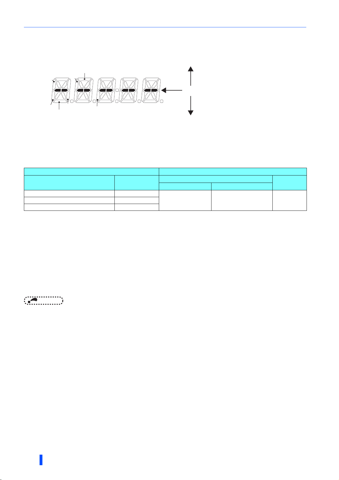
Parameter details
Monitoring I/O terminals on the operation panel (FR-DU08) (Pr.52)
• When Pr.52 = "25", the I/O terminal states can be monitored on the operation panel (FR-DU08).
• When a terminal is ON, the corresponding LED segment is ON . The center LED segments are always ON.
Segments corresponding to input terminals
The center LED segments are always ON.
Segments corresponding to output terminals
SOF
RYB
RSO
RES
RYA
LOH
ABC
Monitoring and resetting cumulative power (Pr.46 and Pr.48)
• When the cumulative power is monitored (Pr.52 = "8"), the input power monitor value is added up and is updated in 100 ms
increments. (The values are registered in EEPROM every hour.)
• Increments and ranges of monitoring on the operation panel or parameter unit or via communication (RS-485
communication) are as follows.
On operation panel / parameter unit ∗1 Via communication
Range Increment
0 to 999.99 kWh 0.01 kWh
10000 to 99999 kWh 1 kWh
∗1 Power is measured in the range of 0 to 99999.99 kWh, and the values are displayed in five digits.
After the watt-hour meter (cumulative power counter) reaches "999.99" (999.99 kWh), the meter displays values in 0.1 increments such as
"1000.0" (1000.0 kWh).
Pr.46 = 10 Pr.46 = 9999
0 to 9999 kWh
• The decimal point position on the watt-hour meter can be shifted to left. The number of digits to be shifted is equal to the
setting of Pr.48.
For example, when Pr.48 = "2", the cumulative power value 1278.56 kWh is displayed as 12.78 (in 100 kWh increments) on
the PU or displayed as 12 on a display used for monitoring via communication.
• When Pr.48 = "0 to 4", the meter stops at the maximum number. When Pr.48 = "9999", the meter returns to 0 and the
counting starts again.
• After the setting of Pr.48 is changed, the watt-hour meter holds the cumulative value.
• Writing "0" in Pr.46 clears the cumulative power monitor.
Range
0 to 65535 kWh
(initial value)
Increment
1 kWh1000.0 to 9999.9 kWh 0.1 kWh
NOTE
• When Pr.46 is read just after "0" has been written in Pr.46, the setting "9999" or "10" is displayed.
Displaying electricity cost (Pr.896)
• When the electricity cost is selected as a monitor item (Pr.52 = "28"), the electricity cost calculated from the electricity rate
(cost per kWh) set in Pr.896 and the cumulative energy is displayed.
Monitoring cumulative energization time (Pr.47)
• When the cumulative energization time is selected as a monitor item (Pr.52 = "9"), the counter of cumulative energization
time since the converter shipment accumulated every hour is displayed.
• When the cumulative energization time counter reaches 65535, it starts from 0 again. The number of times the cumulative
energization time counter reaches 65535 can be checked with Pr.47.
96
PARAMETERS

Parameter details
3.5.12 Operation selection at instantaneous power
failure (Pr.57)
Use this parameter to set whether the multifunction regeneration converter restarts the operation at the power
restoration after an instantaneous power failure occurs.
Pr. Name Initial value Setting range Description
0
57 Restart selection
• When the automatic restart after instantaneous power failure is selected on the inverter, set "0" in Pr.57 Restart selection
of the converter.
If Pr.57 = "9999" even though the automatic restart after instantaneous power failure is activated in the inverter, the
converter shows the fault indication "E.E" and stops the inverter operation at the instantaneous power failure.
9999
9999
CAUTION
The motor and machine will start suddenly after occurrence of an instantaneous power failure (after the reset time has elapsed).
Stay away from the motor and machine when automatic restart after instantaneous power failure has been selected.
The converter restarts operation at the power
restoration from instantaneous power failure.
The converter does not restart operation
automatically at the power restoration from
instantaneous power failure.
3.5.13 Free parameter (Pr.58 and Pr.59)
Any number within the setting range of 0 to 9999 can be input.
For example, these numbers can be used:
• As a unit number when multiple units are used.
• As a pattern number for each operation application when multiple units are used.
• As the year and month of introduction or inspection.
Pr. Name Initial value Setting range Description
58 Free parameter 1
59 Free parameter 2
9999 0 to 9999
9999 0 to 9999
Any value can be input. The settings are
retained even if the converter power is
turned OFF.
NOTE
• Pr.58 and Pr.59 do not influence the operation of the converter.
3.5.14 Disabling keys on the operation panel (Pr.61)
The keys on the operation panel can be disabled.
Pr. Name Initial value Setting range Description
61 Key lock operation selection
• The setting dial and keys on the operation panel can be disabled to prevent unexpected parameter changes.
•Set Pr.61 to "10" and then press for 2 seconds to disable setting dial and keys.
• When the setting dial and keys are disabled, " " appears on the operation panel. If the setting dial or any key is
0
0 The keys are operable.
10 The keys are inoperable.
3
used while keys are inoperable, " " appears on the operation panel. (When the setting dial or any key is not
used for 2 seconds, the operation panel switches to the monitor mode.)
• To enable the setting dial and keys again, press for 2 seconds.
NOTE
• Even if the setting dial and keys are disabled, the converter reset by using are enabled.
• Switching of the monitor item is disabled.
• The PU stop warning cannot be reset by using keys while the key locks are enabled.
PARAMETERS
97
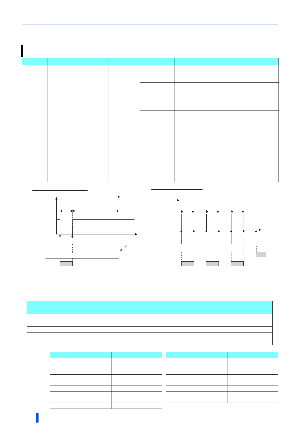
Parameter details
3.5.15 Retry function (Pr.65, Pr.67 to Pr.69)
This function allows the converter the retry operation (automatic reset and restart) after a fault occurred. Faults which
trigger the retry operation can be selected.
Pr. Name Initial value Setting range Description
65 Retry selection
67
Number of retries at fault
occurrence
68 Retry waiting time
69 Retry count display erase
Retry success example
0 0 to 4
0 The retry function disabled.
1 to 10
101 to 110
0
1001 to 1010
1101 to 1110
1 s 0.1 to 600 s
00
Retry succeeded.
Retry failure example
Faults which trigger the retry operation can be
selected. (Refer to the table in the next page.)
Set the number of retries at a fault occurrence.
A fault output is not provided during the retry operation.
Set the number of retries at a fault occurrence. (The
setting value minus 100 is the number of retries.)
A fault output is provided during the retry operation.
Set the number of retries at a fault occurrence. (The
setting value minus 1000 is the number of retries.)
A fault output is not provided during the retry operation.
The RDY signal is ON during retry.
Set the number of retries at a fault occurrence. (The
setting value minus 1100 is the number of retries.)
A fault output is provided during the retry operation.
The RDY signal is ON during retry.
Set the time delay from when a converter fault occurs
until the retry operation starts.
Setting "0" clears the retry success counter ("retry
success" means that the converter successfully
restarts).
Converter
operation
status
Retry success counter
During retry
signal (RTY)
Pr.68
0
Fault
occurred.
Retry starts.
ON
(Pr.68×4) s
(6 s at minimum)
Time
Counter
incremented by 1.
During retrysignal
Converter
operation
status
Fault signal
(ALM)
(RTY)
Pr.68
0
First retry
Fault
occurred.
ON ON ON
Pr.68 Pr.68
second retry
Fault
occurred.
Fault
occurred.
Third retry
Time
Retry failed.
(E.K fault)
ON
• When a fault occurs and a protective function is activated while the retry function is enabled, the retry function automatically
deactivates (resets) the protective function and restarts the operation after a lapse of the time set in Pr.68.
• The retry function is enabled when the Pr.67 setting is other than "0." Set the number of retries at activation of the
protective function in Pr.67.
Pr.67 setting Retry times Fault output
0 The retry function disabled. ⎯⎯
1 to 10 Number of times equal to Pr.67 setting No Not held
101 to 110 Number of times calculated by subtracting 100 from Pr.67 setting Yes Not held
1001 to 1010 Number of times calculated by subtracting 1000 from Pr.67 setting No Held
1101 to 1110 Number of times calculated by subtracting 1100 from Pr.67 setting Yes Held∗1
∗1 The RDY signal state during retries by fault is as follows.
RDY signal ON
state during retry
∗1
Retry-inducing fault RDY signal ON state Retry-inducing fault RDY signal ON state
E.C (Converter overload trip
E.A (Overcurrent trip) Held
E.B (Overvoltage trip) Held
E.G (Input phase loss) Held E.F (Undervoltage) Not held
E.Q (Communication option
fault)
E.8 (Input power supply fault 1) Held
Held
(electronic thermal relay
function))
E.E (Instantaneous power
failure)
E.H (External thermal relay
operation)
Not held
Not held
Not held
98
PARAMETERS

Parameter details
• When the protective function is activated after retries are attempted consecutively more than the number of times set in
Pr.67, the Retry count excess fault (E.K) occurs and the converter output is shut off. (Refer to the figure of retry failure
example.)
• Use Pr.68 to set the waiting time from when the converter output has been shut off until a retry is made in the range of 0 to
600 seconds.
• The cumulative count in Pr.69 increases by 1 when a retry is successful. Retry is regarded as successful when normal
operation continues without a fault for the Pr.68 setting multiplied by four or longer (6 seconds at the shortest).
(When retry is successful, the cumulative number of retry failures is cleared.)
• Writing "0" in Pr.69 clears the retry counter.
During a retry, the RTY signal is ON. For the RTY signal, set "11 (positive logic)" or "111 (negative logic)" in any of Pr.11,
Pr.12, and Pr.16 (Output terminal function selection) to assign the function.
NOTE
• Changing the terminal assignment using Pr.11, Pr.12, or Pr.16 (Output terminal function selection) may affect the other
functions. Set parameters after confirming the function of each terminal.
• Faults which trigger the retry operation can be selected with Pr.65. The faults not described in the following table do not
enable the retry function. (For the fault details, refer to page 134.)
"●" indicates the fault selected.
Retry-inducing fault
E.A (Overcurrent trip)
E.B (Overvoltage trip)
E.C (Converter overload trip (electronic thermal relay function))
E.E (Instantaneous power failure)
E.F (Undervoltage)
E.G (Input phase loss)
E.H (External thermal relay operation)
E.Q (Communication option fault)
E.8 (Input power supply fault 1)
0 1 2 3 4
●● ●●
●●●●
●
●●
●●
●●
●
●●
●●
Pr.65 setting
NOTE
• Only the first fault is recorded in the fault history during retries.
• If a fault that does not trigger the retry operation occurs during retries, the converter output is shut off with the fault indication
after the retries finish.
• The fault reset by the retry function does not reset the accumulated data such as the electronic thermal relay function data.
(The reset result is different from the power-ON reset.)
CAUTION
When setting the retry function enabled, stay away from the motor and machine. The motor and machine will start suddenly (after the
reset time has elapsed) after the shutoff.
PARAMETERS
3
99
 Loading...