

Mitsubishi Electric FR-V560 Instruction Manual
VECTOR INVERTER
FR-V560
INSTRUCTION MANUAL (Detailed)
HIGH PRECISION & HIGH
RESPONSE VECTOR INVERTER
FR-V560-2.2K to 55K-NA
WIRING
VECTOR CONTROL
WITH ENCODER
VECTOR CONTROL
WITHOUT ENCODER
PARAMETERS
PROTECTIVE
FUNCTIONS
1
2
3
4
5
SPECIFICATIONS
6
Thank you for choosing this Mitsubishi vector inverter. This Instruction Manual (detailed) provides instructions for advanced use of the
FR-V500 series inverters. Incorrect handling might cause an unexpected fault. Before using the inverter, always read this Instruction
Manual and the Instruction Manual (basic) [IB-0600134E] packed with the product carefully to use the equipment to its optimum
performance.
This instruction manual uses the International System of Units (SI). The measuring units in the yard and pound system are indicated in
parentheses as reference values.
This section is specifically about safety matters
Do not attempt to install, operate, maintain or inspect the inverter until you have read through the Instruction Manual (basic) and
appended documents carefully and can use the equipment correctly. Do not use the inverter until you have a full knowledge of the
equipment, safety information and instructions. In this Instruction Manual, the safety instruction levels are classified into "WARNING"
and "CAUTION".
WARNING
CAUTION
Note that even the level may lead to a serious consequence according to conditions. Please follow the
instructions of both levels because they are important to personnel safety.
Assumes that incorrect handling may cause hazardous conditions, resulting in death or severe injury.
Assumes that incorrect handling may cause hazardous conditions, resulting in medium or slight
injury, or may cause physical damage only.
CAUTION
1. Electric Shock Prevention
WARNING
While power is on or when the inverter is running, do not open the front cover. You may get an electric shock.
Do not run the inverter with the front cover removed. Otherwise, you may access the exposed high-voltage terminals or the charging
part of the circuitry and get an electric shock.
Even If power is off, do not remove the front cover except for wiring or periodic inspection. You may access the charged inverter
circuits and get an electric shock.
Before starting wiring or inspection, switch power off, wait for more than at least 10 minutes and check for the presence of any
residual voltage with a meter etc.
This inverter must be grounded. Grounding must conform to the requirements of national and local safety regulations and electrical
codes. (JIS, NEC section 250, IEC 536 class 1 and other applicable standards).
Any person who is involved in wiring or inspection of this equipment should be fully competent to do the work.
Always install the inverter before wiring. Otherwise, you may get an electric shock or be injured.
Perform setting dial and key operations with dry hands to prevent an electric shock.
Do not subject the cables to scratches, excessive stress, heavy loads or pinching. Otherwise, you may get an electric shock.
Do not change the cooling fan while power is on. It is dangerous to change the cooling fan while power is on.
2. Fire Prevention
CAUTION
Mount the inverter to incombustible material. Mounting it to or near combustible material can cause a fire.
If the inverter has become faulty, switch off the inverter power. A continuous flow of large current could cause a fire.
When a brake resistor is used, use an alarm signal to switch power off. Otherwise, the brake resistor will overheat abnormally due to
a brake transistor or other fault, resulting in a fire.
Do not connect a resistor directly to the DC terminals P, N. This could cause a fire.
3.Injury Prevention
CAUTION
Apply only the voltage specified in the instruction manual to each terminal to prevent damage etc.
Ensure that the cables are connected to the correct terminals. Otherwise damage etc. may occur.
Always make sure that polarity is correct to prevent damage etc.
While power is on and for some time after power-off, do not touch the inverter or brake resistor as they are hot and you may get burnt.
4. Additional Instructions
Also note the following points to prevent an accidental failure, injury, electric shock, etc.
1) Transportation and installation
CAUTION
When carrying products, use correct lifting gear to prevent injury.
Do not stack the inverter boxes higher than the number recommended.
Ensure that installation position and material can withstand the weight of the inverter.
Do not operate if the inverter is damaged or has parts missing.
When carrying the inverter, do not hold it by the front cover or setting dial; it may fall off or fail.
Do not stand or rest heavy objects on the inverter.
Check the inverter mounting orientation is correct.
Prevent screws, wire fragments, other conductive bodies, oil or other flammable substances from entering the inverter.
Do not drop the inverter, or subject it to impact
Use the inverter under the following environmental conditions:
Ambient temperature -10°C to +50°C (14°F to 122°F) (non-freezing)
Ambient humidity 90%RH or less (non-condensing)
Storage temperature -20°C to +65°C* (-4°F to 149°F)
Ambience Indoors (free from corrosive gas, flammable gas, oil mist, dust and dirt)
Environment
Altitude, vibration
*Temperature applicable for a short time, e.g. in transit.
Maximum 1000m(3280.80feet) above sea level for standard operation.
After that derate by 3% for every extra 500m(1640.40feet) up to 2500m (8202.00feet) (91%).
5.9m/s 2 or less (conforming to JIS C 0040)
A-1
2) Wiring
CAUTION
Do not fit capacitive equipment such as power factor correction capacitor, surge suppressor or radio noise filter to the inverter output
side.
The connection orientation of the output cables (terminals U, V, W) to the motor will affect the direction of rotation of the motor.
3) Trial run
CAUTION
Check all parameters, and ensure that the machine will not be damaged by a sudden start-up.
4) Operation
WARNING
When you have chosen the retry function, stay away from the equipment as it will restart suddenly after an alarm stop.
The [STOP] key is valid only when the appropriate function setting has been made. Prepare an emergency stop switch separately.
Make sure that the start signal is off before resetting the inverter alarm. A failure to do so may restart the motor suddenly.
The load used should be a three-phase induction motor only. Connection of any other electrical equipment to the inverter output may
damage the equipment.
Do not modify the equipment.
CAUTION
The electronic thermal relay function does not guarantee protection of the motor from overheating.
Do not use a magnetic contactor on the inverter input for frequent starting/stopping of the inverter.
Use a noise filter to reduce the effect of electromagnetic interference. Otherwise nearby electronic equipment may be affected.
Take measures to suppress harmonics. Otherwise power from the inverter may heat/damage the power capacitor and generator.
When a 575V class motor is inverter-driven, it should be insulation-enhanced or surge voltages suppressed. Surge voltages
attributable to the wiring constants may occur at the motor terminals, deteriorating the insulation of the motor.
When parameter clear or all clear is performed, each parameter returns to the factory setting. Re-set the required parameters before
starting operation.
The inverter can be easily set for high-speed operation. Before changing its setting, fully examine the performances of the motor and machine.
In addition to the inverter's holding function, install a holding device to ensure safety.
Before running an inverter which had been stored for a long period, always perform inspection and test operation. In addition to the
inverter's holding function, install a holding device to ensure safety.
5) Emergency stop
CAUTION
Provide a safety backup such as an emergency brake which will prevent the machine and equipment from hazardous conditions if
the inverter fails.
When the breaker on the inverter primary side trips, check for the wiring fault (short circuit), damage of the inner parts of the inverter,
etc. Identify the cause of the trip, then remove the cause and power on the breaker.
When any protective function is activated, take the appropriate corrective action, then reset the inverter, and resume operation.
6) Maintenance, inspection and parts replacement
CAUTION
Do not carry out a megger (insulation resistance) test on the control circuit of the inverter.
7) Disposing of the inverter
CAUTION
Treat as industrial waste
8) General instructions
Many of the diagrams and drawings in this Instruction Manual show the inverter without a cover, or partially open. Never operate the
inverter in this manner. Always replace the cover and follow this Instruction Manual when operating the inverter.
A-2

CONTENTS
1 WIRING 1
1.1 Basic configuration and connection of peripheral devices............................. 2
1.1.1 Basic configuration.............................................................................................................................2
1.1.2 Selection of peripheral devices ..........................................................................................................3
1.2 Connection diagram ............................................................................................4
1.3 Internal block diagram......................................................................................... 5
1.4 Main circuit terminal specifications ................................................................... 6
1.4.1 Specification of main circuit terminal ..................................................................................................6
1.4.2 Cables and wiring length....................................................................................................................7
1.5 Motor ..................................................................................................................... 8
1.5.1 Encoder cable and encoder setting....................................................................................................8
1.5.2 Inverter-driven 575V class motor .....................................................................................................10
1.6 Connection of stand-alone option units .......................................................... 11
1.6.1 Connection of the external brake resistor.........................................................................................11
1.6.2 Connection of the brake unit (FR-BU-C) ..........................................................................................12
1.6.3 Connection of the power factor improving DC reactor .....................................................................12
1.7 Control circuit terminal specifications ............................................................ 13
1.7.1 Specification of control circuit terminal.............................................................................................13
1.7.2 Control circuit terminal layout...........................................................................................................15
1.7.3 Wiring instructions............................................................................................................................15
1.7.4 Connecting the control circuit to a power supply separately from the main circuit...........................15
1.7.5 Changing the control logic................................................................................................................16
1.8 Precautions for use of the vector inverter....................................................... 18
1.9 Others ................................................................................................................. 19
1.9.1 Leakage currents and countermeasures..........................................................................................19
1.9.2 Power off and magnetic contactor (MC)...........................................................................................21
1.9.3 Installation of power factor improving reactor...................................................................................21
1.9.4 Notes on grounding..........................................................................................................................22
1.9.5 Inverter-generated noises and their reduction techniques ...............................................................23
1.9.6 Power supply harmonics ..................................................................................................................25
1.9.7 Using the PU connector for computer link........................................................................................26
1.10 Input terminals ................................................................................................... 29
1.10.1 Run (start) and stop (STF, STR, STOP) ..........................................................................................29
1.10.2 External thermal relay input (OH).....................................................................................................30
1.10.3 Speed setting potentiometer connection (10E, 2 (1), 5)...................................................................30
1.10.4 Torque setting input signal and motor-generated torque (terminals 3, 5) ........................................31
1.10.5 Meter connection method and adjustment (DA1, DA2)....................................................................31
1.10.6 Common terminals (SD, 5, SE) ........................................................................................................32
1.10.7 Signal inputs by contact-less switches.............................................................................................32
1.11 How to use the input signals (assigned terminals DI1 to DI4, STR)
(Pr. 180 to Pr. 183, Pr. 187)................................................................................ 33
1.11.1 Multi-speed setting (RL, RM, RH, REX signals): Pr. 180 to Pr. 183, Pr. 187 setting
"0, 1, 2, 8"
Remote setting (RL, RM, RH signals): Pr. 180 to Pr. 183, Pr. 187 setting "0, 1, 2" .........................33
1.11.2 Second function selection/second motor switchover (RT signal)
: Pr. 180 to Pr. 183, Pr. 187 setting "3" ............................................................................................33
1.11.3 Jog operation (jog signal): Pr. 180 to Pr. 183, Pr. 187 setting "5"....................................................33
1.11.4 Third function selection (X9 signal): Pr. 180 to Pr. 183, Pr. 187 setting "9" .....................................34
I

1.11.5 PU operation external interlock signal (X12 signal): Pr. 180 to Pr. 183, Pr. 187 setting "12"...........34
1.11.6 PID control enable terminal: Pr. 180 to Pr. 183, Pr. 187 setting "14"...............................................34
1.11.7 Brake sequence opening signal (BRI signal): Pr. 180 to Pr. 183, Pr. 187 setting "15" ....................34
1.11.8 PU operation/external operation switchover: Pr. 180 to Pr. 183, Pr. 187 setting "16"......................34
1.11.9 S-pattern acceleration/deceleration C switchover terminal (X20 signal)
: Pr. 180 to Pr. 183, Pr. 187 setting "20" ..........................................................................................34
1.11.10 Orientation command (X22 signal): Pr. 180 to Pr. 183, Pr. 187 setting "22"....................................35
1.11.11 Pre-excitation/servo on (LX signal): Pr. 180 to Pr. 183, Pr. 187 setting "23" ...................................35
1.11.12 Output stop (MRS signal): Pr. 180 to Pr. 183, Pr. 187 setting "24"..................................................35
1.11.13 Start self-holding selection (STOP signal): Pr. 180 to Pr. 183, Pr. 187 setting "25".........................35
1.11.14 Control mode changing (MC signal): Pr. 180 to Pr. 183, Pr. 187 setting "26"..................................36
1.11.15 Torque restriction selection (TL signal): Pr. 180 to Pr. 183, Pr. 187 setting "27" .............................36
1.11.16 Start time tuning (X28 signal): Pr. 180 to Pr. 183, Pr. 187 setting "28"............................................36
1.11.17 Torque bias selection 1 (X42 signal): Pr. 180 to Pr. 183, Pr. 187 setting "42"
Torque bias selection 2 (X43 signal): Pr. 180 to Pr. 183, Pr. 187 setting "43".................................36
1.11.18 P control selection (P/PI control switchover) (X44 signal):
Pr. 180 to Pr. 183, Pr. 187 setting "44" ............................................................................................37
1.12 How to use the output signals (assigned terminals DO1 to DO3, ABC)
(Pr. 190 to Pr. 192, Pr. 195)................................................................................ 38
1.13 Design information to be checked ................................................................... 40
1.14 Using the second motor....................................................................................41
1.14.1 Wiring diagram (second motor) ........................................................................................................41
1.14.2 Second motor setting parameters ...................................................................................................41
2 VECTOR CONTROL WITH ENCODER 43
2.1 What is vector control? .....................................................................................44
2.2 Speed control ..................................................................................................... 46
2.2.1 Outline of speed control ...................................................................................................................46
2.2.2 Easy gain tuning function block diagram..........................................................................................46
2.3 Fine adjustment of gains for speed control ....................................................47
2.3.1 Control block diagram ......................................................................................................................47
2.3.2 Concept of adjustment of manual input speed control gains............................................................48
2.3.3 Speed control gain adjustment procedure (Pr. 820, Pr. 821)...........................................................48
2.3.4 Troubleshooting................................................................................................................................49
2.3.5 Speed feed forward control, model adaptive speed control (Pr. 877 to Pr. 881)..............................51
2.4 Torque control....................................................................................................53
2.4.1 Outline of torque control...................................................................................................................53
2.5 Fine adjustment for torque control ..................................................................54
2.5.1 Control block diagram ......................................................................................................................54
2.6 Gain adjustment for torque control..................................................................55
2.6.1 Concept of torque control gains .......................................................................................................55
2.6.2 Gain adjustment procedure ..............................................................................................................55
2.6.3 Troubleshooting................................................................................................................................56
2.7 Position control (Pr. 419 to Pr. 430, Pr. 464 to Pr. 494) .................................. 57
2.7.1 Position control step.........................................................................................................................57
2.7.2 Control block diagram ......................................................................................................................58
2.7.3 Parameter.........................................................................................................................................58
2.7.4 Conditional position feed function by contact input (Pr. 419=0) .......................................................60
2.7.5 Setting the electronic gear................................................................................................................61
II

2.7.6 In-position width (Pr. 426) ................................................................................................................63
2.7.7 Excessive level error (Pr. 427) .........................................................................................................63
2.7.8 Pulse monitor selection (Pr. 430) .....................................................................................................63
2.7.9 Concept of position control gains.....................................................................................................63
2.7.10 Troubleshooting................................................................................................................................64
2.7.11 Position control is not exercised normally ........................................................................................65
3 VECTOR CONTROL WITHOUT ENCODER 67
3.1 Speed control (without encoder)...................................................................... 68
3.1.1 Outline of speed control ...................................................................................................................68
3.2 Fine adjustment of gains for speed control (without encoder) ..................... 69
3.2.1 Control block diagram ......................................................................................................................69
3.2.2 Concept of adjustment of manual input speed control gains............................................................70
3.2.3 Speed control gain adjustment procedure (Pr. 820, Pr. 821)...........................................................70
3.2.4 Troubleshooting................................................................................................................................71
3.2.5 Speed feed forward control (Pr. 877 to Pr. 881)...............................................................................72
3.3 Torque control (without encoder) .................................................................... 73
3.3.1 Outline of torque control...................................................................................................................73
3.4 Fine adjustment for torque control (without encoder) ................................... 74
3.4.1 Control block diagram ......................................................................................................................74
3.5 Gain adjustment for torque control (without encoder)................................... 75
3.5.1 Concept of torque control gains .......................................................................................................75
3.5.2 Gain adjustment procedure ..............................................................................................................75
3.5.3 Troubleshooting................................................................................................................................76
CONTENTS
4 PARAMETERS 77
4.1 Parameter lists ................................................................................................... 78
4.2 At-a-glance guide to functions ......................................................................... 86
4.3 Basic functions (Pr. 0 to Pr. 9)..........................................................................89
4.3.1 Torque boost (Pr. 0) .........................................................................................................................89
4.3.2 Maximum and minimum speed settings (Pr. 1, Pr. 2) .....................................................................89
4.3.3 Base frequency, base frequency voltage (Pr. 3, Pr. 19)...................................................................90
4.3.4 Multi-speed operation (Pr. 4 to Pr. 6, Pr. 24 to Pr. 27, Pr. 232 to Pr. 239)......................................90
4.3.5 Acceleration and deceleration times (Pr. 7, Pr. 8, Pr. 20, Pr. 21, Pr. 44, Pr. 45, Pr. 110, Pr. 111) .91
4.3.6 Motor overheat protection (Pr. 9, Pr. 452, Pr. 876 ) .........................................................................93
4.4 Standard operation functions (Pr. 10 to Pr. 16) ..............................................95
4.4.1 DC injection brake operation (Pr. 10, Pr.11, Pr. 12, Pr.802, Pr. 850)..............................................95
4.4.2 Starting speed (Pr. 13) .....................................................................................................................97
4.4.3 Jog operation (Pr. 15, Pr. 16)...........................................................................................................98
4.5 Operation selection functions 1 (Pr. 17 to Pr. 37)...........................................98
4.5.1 Inverter output stop (MRS) (Pr. 17) ..................................................................................................98
4.5.2 Torque restriction (Pr. 22, Pr. 803, Pr. 810, Pr. 812 to Pr. 817)...................................................100
4.5.3 RH, RM, RL signal input compensation (Pr. 28) ............................................................................101
4.5.4 S-pattern acceleration/deceleration curve (Pr. 29, Pr. 140 to Pr. 143, Pr. 380 to Pr. 383) ............102
4.5.5 Regenerative brake duty (Pr. 30, Pr. 70)........................................................................................105
4.5.6 Speed jump (Pr. 31 to Pr. 36).........................................................................................................106
4.5.7 Speed display (Pr. 37, Pr. 144) ......................................................................................................106
III

4.6 Output terminal functions (Pr. 41 to Pr. 50)...................................................108
4.6.1 Up-to-speed sensitivity (Pr. 41)......................................................................................................108
4.6.2 Speed detection (Pr. 42, Pr. 43, Pr. 50, Pr. 116)............................................................................108
4.7 Display functions 1 (Pr. 52 to Pr. 56)..............................................................110
4.7.1 Monitor display/DA1, DA2 terminal function selection (Pr. 52 to Pr. 54, Pr. 158) .........................110
4.7.2 Monitoring reference (Pr. 55, Pr. 56, Pr. 866) ................................................................................113
4.8 Automatic restart (Pr. 57, Pr. 58) .................................................................... 114
4.8.1 Automatic restart after instantaneous power failure (Pr. 57, Pr. 58, Pr. 162 to Pr. 165) ................114
4.9 Additional functions (Pr. 59) ...........................................................................116
4.9.1 Remote setting function selection (Pr. 59 ) ....................................................................................116
4.10 Brake sequence (Pr. 60, Pr. 278 to Pr. 285) ...................................................118
4.10.1 Brake sequence function (Pr. 60, Pr. 278 to Pr. 285).....................................................................118
4.11 Operation selection function 2 (Pr. 65 to Pr. 79)...........................................121
4.11.1 Retry function (Pr. 65, Pr. 67 to Pr. 69)..........................................................................................121
4.11.2 Applied motor (Pr. 71, Pr. 450).......................................................................................................123
4.11.3 PWM carrier frequency selection (Pr. 72, Pr. 240).........................................................................124
4.11.4 Speed setting signal on/off selection (Pr. 73).................................................................................125
4.11.5 Reset selection/disconnected PU detection/PU stop selection (Pr. 75).........................................127
4.11.6 Parameter write disable selection (Pr. 77) .....................................................................................128
4.11.7 Reverse rotation prevention selection (Pr. 78 )..............................................................................129
4.11.8 Operation mode selection (Pr. 79) .................................................................................................129
4.12 Offline auto tuning (Pr. 80 to Pr. 96)............................................................... 132
4.12.1 Offline auto tuning function
(Pr. 9, Pr. 80, Pr. 81, Pr. 83, Pr. 84, Pr. 71, Pr. 96, Pr. 450, Pr. 452).............................................132
4.12.2 Parameters.....................................................................................................................................132
4.12.3 Execution of offline auto tuning ......................................................................................................133
4.12.4 Utilizing or changing offline auto tuning data for use......................................................................136
4.12.5 Setting the motor constants directly ...............................................................................................137
4.12.6 Direct input + offline auto tuning.....................................................................................................138
4.13 Online auto tuning (Pr. 95) .............................................................................. 139
4.13.1 Online auto tuning selection (Pr. 95, Pr. 9, Pr. 71, Pr. 80, Pr. 81 ).................................................139
4.14 Communication functions (Pr. 117 to Pr. 124) .............................................. 141
4.14.1 Computer link operation (RS-485 communication) (Pr. 117 to Pr. 124)........................................141
4.14.2 E2PROM write selection (Pr. 342) .................................................................................................152
4.15 PID control (Pr. 128 to Pr. 134) .......................................................................152
4.15.1 PID control (Pr. 128 to Pr. 134)......................................................................................................152
4.16 Current detection (Pr. 150 to Pr. 153)............................................................. 159
4.16.1 Output current detection function (Pr. 150, Pr. 151).......................................................................159
4.16.2 Zero current detection (Pr. 152, Pr. 153)........................................................................................160
4.17 Auxiliary functions (Pr. 156, Pr. 157).............................................................. 161
4.17.1 Stall prevention operation selection (Pr. 156) ................................................................................161
4.17.2 OL signal output timer (Pr. 157) .....................................................................................................162
4.18 Display function 3 (Pr. 160)............................................................................. 163
4.18.1 Extended function display selection (Pr. 160) ................................................................................163
4.19 Initial monitor (Pr. 171) ....................................................................................163
4.19.1 Actual operation hour meter clear (Pr. 171) ...................................................................................163
4.20 Terminal assignment functions (Pr. 180 to Pr. 195) .....................................163
IV

4.20.1 Input terminal function selection (Pr. 180 to Pr. 183, Pr. 187).......................................................163
4.20.2 Output terminal function selection (Pr. 190 to Pr. 192, Pr. 195).....................................................165
4.21 Auxiliary function (Pr. 244) ............................................................................. 167
4.21.1 Cooling fan operation selection (Pr. 244).......................................................................................167
4.22 Stop selection function (Pr. 250) .................................................................... 167
4.22.1 Stop selection (Pr. 250)..................................................................................................................167
4.23 Operation selection function (Pr. 251) ........................................................... 168
4.23.1 Output phase failure protection selection (Pr. 251)........................................................................168
4.24 Additional function 2 (Pr. 252, Pr. 253) ..........................................................169
4.24.1 Override bias, gain (Pr. 252, Pr. 253).............................................................................................169
4.25 Power failure stop functions (Pr. 261 to Pr. 266) .......................................... 169
4.25.1 Power-failure deceleration stop function (Pr. 261 to Pr. 266).........................................................169
4.26 Droop (Pr. 286 to Pr. 288) ................................................................................171
4.26.1 Droop control (Pr. 286, Pr. 287, Pr. 288)........................................................................................171
4.27 Orientation (Pr. 350 to Pr. 362, Pr. 393 to Pr. 399) ........................................ 172
4.27.1 Orientation control (Pr. 350, Pr. 351, Pr. 356, Pr. 357, Pr. 360 to Pr. 362, Pr. 393,
Pr. 396 to Pr. 399).........................................................................................................................172
4.28 Control system function (Pr. 374) .................................................................. 179
4.28.1 Overspeed detection (Pr. 374) .......................................................................................................179
4.29 Position control (Pr. 419 to Pr. 430, Pr. 464 to Pr. 494) ................................ 180
4.29.1 Position control (Pr. 419 to Pr. 430, Pr. 464 to Pr. 494).................................................................180
4.30 Remote output (Pr. 495 to Pr.497) .................................................................. 181
4.30.1 Remote output function (Pr. 495 to Pr.497)....................................................................................181
4.31 Operation selection functions 4 (Pr. 800 to Pr. 809).....................................182
4.31.1 Control selection (Pr. 800, Pr. 451)................................................................................................182
4.31.2 Torque characteristic selection (Pr. 801)........................................................................................182
4.31.3 Torque command right selection (Pr. 804 to Pr. 806) ....................................................................184
4.31.4 Speed restriction (Pr. 807 to Pr. 809).............................................................................................185
CONTENTS
4.32 Control system functions (Pr. 818 to Pr. 837) ............................................... 187
4.32.1 Easy gain tuning selection (Pr. 818, Pr. 819).................................................................................187
4.32.2 Speed loop proportional gain setting (Pr. 820, Pr. 830) .................................................................187
4.32.3 Speed control integral time setting (Pr. 821, Pr. 831) ....................................................................187
4.32.4 Speed setting circuit filter function (Pr. 822, Pr. 832) .....................................................................187
4.32.5 Speed detection filter function (Pr. 823, Pr. 833) ...........................................................................188
4.32.6 Current loop proportional gain setting for vector control (Pr. 824, Pr. 834)...................................188
4.32.7 Current control integral time setting for vector control (Pr. 825, Pr. 835)......................................188
4.32.8 Torque setting filter function (Pr. 826, Pr. 836) ..............................................................................188
4.32.9 Torque detection filter function (Pr. 827, Pr. 837) ..........................................................................189
4.32.10 Model speed control gain (Pr. 828) ................................................................................................189
4.33 Torque biases (Pr. 840 to Pr. 848) ..................................................................189
4.33.1 Torque bias function (Pr. 840 to Pr. 848) .......................................................................................189
4.34 Additional functions (Pr. 851 to Pr. 865)........................................................ 192
4.34.1 Selection of number of encoder pulses (Pr. 851)...........................................................................192
4.34.2 Selection of encoder rotation direction (Pr. 852)............................................................................192
4.34.3 Excitation ratio (Pr. 854).................................................................................................................193
4.34.4 Notch filter (Pr. 862, Pr. 863)..........................................................................................................193
4.34.5 Torque detection (Pr. 864) .............................................................................................................194
V

4.34.6 Low speed detection (Pr. 865) .......................................................................................................194
4.35 Display function (Pr. 867)................................................................................ 195
4.35.1 DA1 output response level adjustment (Pr. 867)............................................................................195
4.36 Terminal function assignment (Pr. 868).........................................................195
4.36.1 No. 1 terminal function assignment (Pr. 868).................................................................................195
4.37 Protective functions (Pr. 870 to Pr. 874) ........................................................ 196
4.37.1 Speed deviation excessive (Pr. 870, Pr. 871) ................................................................................196
4.37.2 Speed restriction (Pr. 873) .............................................................................................................197
4.37.3 Stop by OLT level prevention (Pr. 874) ..........................................................................................197
4.38 Operation selection functions 5 (Pr. 875) ...................................................... 198
4.38.1 Fault definition (Pr. 875).................................................................................................................198
4.39 Control system function 2 (Pr. 877 to Pr. 881) .............................................. 198
4.39.1 Speed feed forward control, model adaptive speed control (Pr. 877 to Pr. 881)...........................198
4.40 Maintenance function (Pr. 890 to Pr. 892)...................................................... 199
4.40.1 Maintenance output function (Pr. 890 to Pr. 892)...........................................................................199
4.41 Calibration functions (Pr. 900 to Pr. 920).......................................................200
4.41.1 DA1/DA2 terminal calibration (Pr. 900, Pr. 901).............................................................................200
4.41.2 Biases and gains of speed setting terminals
(speed setting No. 2, torque command No. 3, multi function No. 1 terminal)
(Pr. 902 to Pr. 905, Pr. 917 to Pr. 920)...........................................................................................202
4.42 Additional function (Pr. 990) ...........................................................................205
4.42.1 PU buzzer control (Pr. 990)............................................................................................................205
5 PROTECTIVE FUNCTIONS 207
5.1 Errors (Alarms)................................................................................................. 208
5.1.1 Major faults.....................................................................................................................................208
5.1.2 Minor fault.......................................................................................................................................215
5.1.3 Warnings........................................................................................................................................215
5.1.4 How to recover from PU stop error (PS) ........................................................................................217
5.2 Correspondences between digital and actual characters ...........................218
5.3 Resetting the inverter ...................................................................................... 218
6 SPECIFICATIONS 219
6.1 Model specifications........................................................................................220
6.2 Common specifications .................................................................................. 221
6.3 Outline dimension drawings...........................................................................222
6.3.1 Inverter outline dimension drawings...............................................................................................222
6.3.2 Operation panel (FR-DU04-1) outline dimension drawings............................................................224
6.3.3 Parameter unit (FR-PU04V) outline dimension drawings...............................................................224
APPENDIX 225
Appendix Parameter Data Code Lists.....................................................................226
VI

1
WIRING
This chapter describes the basic "wiring" for use of this
product.
Always read the instructions and other information before
using the equipment.
1.1 Basic configuration and connection of
peripheral devices.................................................2
1.2 Connection diagram .............................................4
1.3 Internal block diagram ..........................................5
1.4 Main circuit terminal specifications .................... 6
1.5 Motor ...................................................................... 8
1.6 Connection of stand-alone option units.............. 11
1.7 Control circuit terminal specifications................ 13
1.8 Precautions for use of the vector inverter ..........18
1.9 Others.....................................................................19
1.10 Input terminals ......................................................29
1.11 How to use the input signals (assigned terminals
DI1 to DI4, STR) (Pr. 180 to Pr. 183, Pr. 187)...........
1.12 How to use the output signals (assigned terminals
DO1 to DO3, ABC) (Pr. 190 to Pr. 192, Pr. 195)........
1.13 Design information to be checked ......................40
1.14 Using the second motor ....................................... 41
33
38
1
2
3
<Abbreviations>
DU : Operation panel (FR-DU04-
PU : Operation panel (FR-DU04-
Inverter : Mitsubishi vector inverter FR-V500 series
Pr. : Parameter number
PU operation : Operation using the PU (FR-DU04-
External operation : Operation using the control circuit signals
Combined operation : Operation using both the PU (FR-DU04-
operation
<Trademarks>
CC-Link is a registered trademark of CC-Link Partner Association.
Ethernet is a registered trademark of XEROX corporation.
DeviceNet is a registered trademark of ODVA (Open DeviceNet Vender Association, Inc.)
Profibus is a registered trademark of PROFIBUS User Organization.
Other company and product names herein are the trademarks or registerd trademarks of
their respective owners.
1)
1) and parameter unit (FR-PU04V)
1/FR-PU04V)
1/FR-PU04V) and external
1
4
5
6
Basic configuration and connection
of peripheral devices
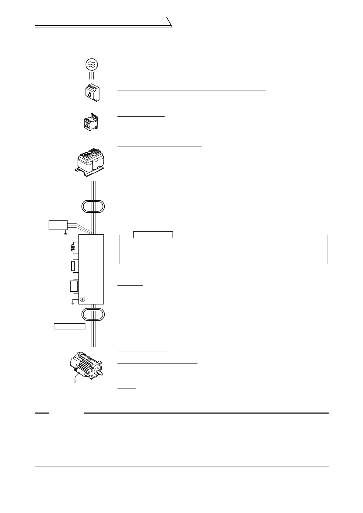
1.1 Basic configuration and connection of peripheral devices
1.1.1 Basic configuration
Power supply
Use within the permissible power supply specifications of the inverter. (Refer to page 220.)
AC reactor
Line noise
filter
Radio noise
filter
Power factor
improvement
reactor
Brake resistor
Brake resistor
(FR-ABR)
Brake unit
(FR-BU-C)
Line noise
filter
Encoder cable
(NFB)
or
(ELB)
(MC)
P
P1
P
PR
P
N
RS
Inverter
FR-V500
T
No-fuse breaker (NFB) or earth leakage circuit breaker (ELB)
The breaker must be selected carefully since an in-rush current flows in the inverter at power-on.
(Refer to page 3.)
Magnetic contactor
Install the magnetic contactor to ensure safety. (For details, refer to page 21.)
Do not use this magnetic contactor to start and stop the inverter. Doing so will cause the inverter
life to be shorten. (Refer to page 3.)
Power factor improvement reactor
The reactors must be used when the power factor is to be improved or the inverter is installed near
a large power supply system (1000kVA or more and wiring distance within 10m
inverter may be damaged if you do not use reactors.
Make selection carefully.
• DC reactor, AC reactor
(Caution) Remove the jumpers across terminals P-P1 to connect to the DC reactor.
(32.81feet)). The
Noise filter
Install a noise filter to reduce the magnetic noise generated from the inverter.
• Line noise filter
Effective in the range from about 1MHz to 10MHz. When more wires are passed through, a
more effective result can be obtained. (Note that the number of wires run through is limited when
fitting to the output side.)
• Radio noise filter
Effective in reducing the noises in the AM radio frequency band. Dedicated filter for the input side.
Inverter
The life of the inverter is influenced by ambient temperature. The ambient temperature should
be as low as possible within the permissible range. This must be noted especially when the
inverter is installed in an enclosure. (Refer to
Wrong wiring might lead to damage of the inverter. The control signal lines must be kept fully
away from the main circuit to protect them from noise. (Refer to page 4.)
the Instruction Manual (basic).)
Brake resistor
(Caution) For the 7.5K or less inverter, remove the jumpers across terminals PR-PX to connect
to the inverter.
Brake unit
(Caution) For the 7.5K or less inverter, remove the jumpers across terminals PR-PX to connect
.
to the inverter.
Motor with encoder
Perform offline auto tuning when exercising vector control with encoder. (Refer to page 132.)
Devices connected to the output
Do not install a power factor correction capacitor, surge suppressor or radio noise filter on the
output side of the inverter.
When installing a no fuse breaker on the output side of the inverter, contact each manufacturer for
Ground
Earth(Ground)
selection of the no fuse breaker.
Ground
To prevent an electric shock, always ground the motor and inverter. For reduction of induction
noise from the power line of the inverter, it is recommended to wire the ground cable by returning it
to the ground terminal of the inverter.
(For details of noise reduction techniques, refer to
page 19.)
CAUTION
• Do not fit capacitive equipment such as power factor correction capacitor, radio noise filter or surge suppressor to the
output side of the inverter. This will cause the inverter to trip or power factor correction capacitor and surge suppressor to
be damaged. If any of the above devices are connected, immediately remove them. (If the radio noise filter is connected,
switching power off during motor operation may result in "E.UVT". In this case, connect the radio noise filter on the primary side of the magnetic contactor.)
• Electromagnetic wave interference
The input/output (main circuit) of the inverter includes harmonic components, which may interfere with the communication devices (such as AM radios) used near the inverter. In this case, install the radio noise filter (for use on the input side
only) or line noise filter to minimize interference.
• For details of peripheral devices, refer to manuals of each peripheral devices.
2

Basic configuration and connection
of peripheral devices
1.1.2 Selection of peripheral devices
Check the motor applicable to the inverter you purchased. Appropriate peripheral devices need to be selected
according to the motor capacity. Refer to the list below and prepare appropriate peripheral devices.
No-fuse Breaker (NFB) or
Motor Output
(kW (HP))
2.2 (3) FR-V560-2.2K-NA 15A 10A K5-15A 7A
3.7 (5) FR-V560-3.7K-NA 20A 15A K5-20A 10A
7.5 (10) FR-V560-7.5K-NA 30A 30A K5-40A 21A
15 (20) FR-V560-15K-NA 60A 50A K5-80A 42A
22 (30) FR-V560-22K-NA 90A 75A K5-110A 59A
37 (50) FR-V560-37K-NA 150A 125A K5-200A 94A
55 (75) FR-V560-55K-NA 200A 175A K5-300A 137A
Applicable
Inverter Type
Earth Leakage Circuit Breaker (ELB)
Standard
With power factor
improving reactor
*
Fuse
Magnetic
Contactor
(AC3)
* •Select the NFB type according to the power supply capacity.
•Install the NFB according to the inverter capacity.
•When the breaker on the inverter primary side trips, check for the wiring fault (short circuit), damage of the inner
parts of the inverter, etc. Identify the cause of the trip, then remove the cause and power on the breaker.
•For installation in the United States and Canada, select circuit breakers authorized by UL and cUL.
1
WIRING
3
Connection diagram
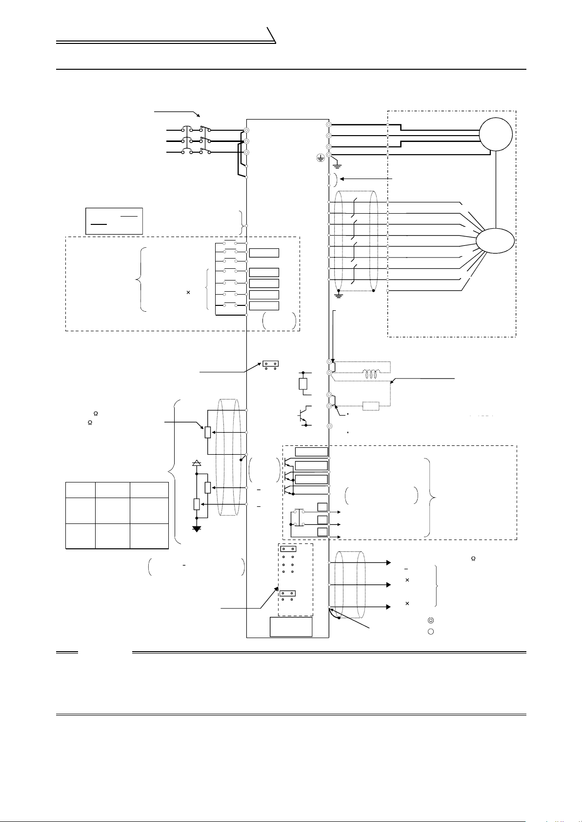
1.2 Connection diagram
Avoid frequent ON-OFF.
Repeated inrush currents at
power-on will shorten the
converter life.
(Switching life is 100,000)
Take care not to
short terminals
PC-SD.
Terminals DI1 to
DI4 and STR vary
in function with
the input terminal
function selection
(Pr. 180 to Pr. 183,
Pr. 187) settings.
Control input signals (no voltage input allowed)
Refer to page 16 for details.
You can select between sink and source.
Speed setting potentiometer
1/2W 1k
2W 1k is recommended for use
when speed setting is changed
frequently.
Terminal
10E, 2, 5
Torque
3
3-phase AC
power supply
External transistor common
24VDC power supply
Contact input common (source)
Forward rotation start
Reverse rotation start
Reset
Analog command
input
Speed
Control
Main
speed
command
restriction
command
Torque
Control
Speed
restriction
command
Torque
command
Prepare a 10V external power
supply for terminals 1, 3.
Change the jumper connector and
parameter settings according to
the encoder specifications.
Refer to page 9 for details.
NFB MC
Digital input
signal 4
+10V
-10V
External
power supply
+
Vector inverter
Motor
(FR-V500)
R
S
T
R1
S1
PC
STF
STR
RES
DI1(RL)
DI2(RM)
U
V
W
Grounding
OH
SD
PA
PAR
PB
PBR
PZ
PZR
PG
SD
Match phase sequence.
Leave the unused terminals open
A-phase signal output
A-phase inverted signal output
B-phase signal output
B-phase inverted signal output
Z-phase signal output
Z-phase inverted signal output
Power supply terminal
Power supply ground terminal
IM
Encoder
DI3(RH)
DI4(RT)
Contact
SD
input
common
SINK
SOURCE
R
(+10V)
10E
3
2
1
(0 to +10V)
2
5
Analog
input
common
+
1( 10V)
+
3( 10V)
DO1
DO2
DO3
5V
12V
24V
EXT
Differential
Complimentary
PU
connector
Jumper
(When using the
Jumper
power factor
(When using the
improving DC
FR-BEL, remove
reactor, remove
this jumper.)
this jumper.)
P1
P
PX
PR
N
(RUN)
Any of three different
(SU)
signals can be selected
using the parameter.
(IPF)
(Open collector output)
SE
A
B
C
DA1
DA2
5
(Analog output common)
FR-BEL power factor
Power factor
improving DC reactor
improving DC reactor
(option)
FR-ABR high-duty
High-duty
brake resistor
brake resistor
(option)
R
Jumper (Remove this jumper
Jumper (Remove this jumper
when using the FR-ABR.)
when using the high-duty brake resistor.)
Terminal PX is provided for
the 5.5K or less.
7.5K
Terminals DO1 to DO3
Open collector output
common
Alarm output
(Contact output)
(+)
(+)
(-)
load impedance of 10k or more
+
10V
12 bits
1ch
0 to 10V
12 bits
1ch
and ABC vary in function
with the output terminal
function selection
(Pr. 190 to Pr. 192,
Pr. 195) settings.
Analog signal output
Main circuit terminal
Control circuit terminal
Across terminals P
Across terminals P
and PR, connect only
and PR, connect only
the brake resistor.
the optional,
In addition, never
recommended brake
short these terminals.
resistor. In addition,
Terminal PR is
never short these
provided for the 15K
terminals.
or less.
Terminal PR is
provided for the 15K
or less.
CAUTION
• To prevent a malfunction caused by noise, separate the signal cables more than 10cm (3.94 inches)
from the power cables.
• During wiring, do not leave wire off-cuts in the inverter.
Wire off-cuts will cause an alarm, failure or malfunction. Always keep the inverter clean. When drilling
mounting holes in a control box etc., take care not to allow chips and other foreign matter to enter the
inverter.
4
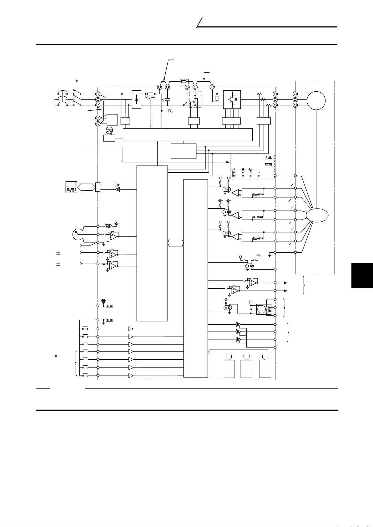
1.3 Internal block diagram
Internal block diagram
Avoid frequent ON-OFF.
Repeated inrush current at power-on
will shorten the converter life.
(switching life is about 100,000 times)
MC
NFB
Jumper
R1
S1
Change the jumper
connector and parameter
according to the encoder
specifications.
RS485
DU04
-1
Output speed
setting
potentiometer
Analog common
0 to 10VDC
0 to 10VDC
External transistor
common
Forward rotation
Reverse rotation
Multi-function
input 4
Four different
signals can be
selected using
the parameters.
Reset
10E
2
5
3
1
SD
STF
STR
RES
DI1
DI2
DI3
DI4
R
S
T
PC
FR-V500
Control
power
supply
SINK
SOURCE
10V
P1
CPU
Jumper: Remove this jumper when connecting
the FR-BEL.
PN
CHARGE
Protective
circuit
power factor improving DC reactor.
Remove this jumper when connecting
Jumper: Remove this jumper when
the external brake resistor.
ASIC
ASIC
connecting the FR-ABR.
(5.5K or less only)
PR
*
TR
PX
*
R
7.5
5.5V
OPTION
#1
12V EXT
24V
TA
TB
TZ
OPTION
#2
RA
CMP
LDV
OPTION
#3
U
V
W
PG
PA
PAR
PB
PBR
PZ
PZR
SD
OH
DA1
DA2
A
Alarm output
B
C
Three different
DO1
signals can be
selected using the
DO2
parameters.
DO3
(Open collector
output)
SE
Motor
U
V
W
Encoder
Analog
signal output
IM
1
WIRING
CAUTION
1. The 22K or more is not equipped with the built-in brake resistor and brake transistor marked *. The brake transistor is
provided for the 15K or less and the built-in brake resistor for the 7.5K or less.
2. Always ground the inverter and motor.
5

Main circuit terminal specifications
1.4 Main circuit terminal specifications
1.4.1 Specification of main circuit terminal
Terminal Symbol Terminal Name Description
R, S, T AC power input Connect to the commercial power supply.
U, V, W Inverter output Connect a three-phase squirrel-cage motor.
Connected to the AC power supply terminals R and S. To retain the alarm
display and alarm output, remove the jumpers from terminals R-R1 and S-S1
and apply external power to these terminals.
R1, S1
P, PR
P, N
P, P1
PR, PX
Power supply for
control circuit
Brake resistor
connection
Brake unit
connection
Power factor
improving DC
reactor connection
Built-in brake circuit
connection
Do not turn off the power supply for control circuit (R1, S1) with the main
circuit power (R, S, T) on. Doing so may damage the inverter. The circuit
should be configured so that the main circuit power (R, S, T) is also turned off
when the power supply for control circuit (R1, S1) is off.
15K or less: 60VA, 22K to 55K: 80VA
Disconnect the jumper from terminals PR-PX (7.5K or less) and connect the
brake resistor across terminals P-PR.
For the 15K or less, connecting the resistor further provides regenerative
braking power.
Connect the optional FR-BU-C brake unit.
Disconnect the jumper from terminals P-P1 and connect the power factor
improving reactor.
When the jumper is connected across terminals PX-PR (factory setting),
the built-in brake circuit is valid. (Provided for the 7.5K or less.)
Ground For grounding the inverter chassis. Must be grounded.
CAUTION
• The inverter will be damaged if power is applied to the inverter output terminals (U, V, W). Never
perform such wiring.
• When connecting the external brake resistor, remove jumpers across terminals PR-PX (7.5K or less).
Refer to page 105.
• When connecting the brake unit (FR-BU-C), remove jumpers across terminals PR-PX (7.5K or less).
Refer to page 12.
6

Main circuit terminal specifications
1.4.2 Cables and wiring length
Select the recommended cable size to ensure that a voltage drop will be 2% max.
If the wiring distance between the inverter and motor is long, the motor torque will decrease due to the voltage drop of the
main circuit cable especially at high-frequency output. The encoder signal will also be affected by the voltage drop.
The following selection example assumes the wiring length of 20m (65.62 feet).
mm
2
HIV Cables
AWG
Applicable Inverter
Ty pe
FR-V560-2.2K, 3.7K-NA M4 1 2-4 2-4 2 2 14 14
FR-V560-7.5K-NA M4 1 5.5-4 2-4 3.5 2 12 14
FR-V560-15K-NA M6 4 5.5-6 5.5-6 5.5 5.5 10 10
FR-V560-22K-NA M6 4 14-6 14-6 14 14 6 6
FR-V560-37K-NA M8 7 22-8 22-8 22 22 4 4
FR-V560-55K-NA M8 7 38-8 38-8 38 38 2 2
Ter minal
Screw Size
Tightening
Torqu e
N·m
Crimping
Terminals
R, S, T U, V, W R, S, T U, V, W R, S, T U, V, W
The line voltage drop can be calculated by the following expression:
Line voltage drop [V]
3 × cable resistance[m /m]× wiring distance[m] × current[A]
=
1000
Use a larger diameter cable when the wiring distance is long or when it is desired to decrease the voltage drop
(torque reduction) in the low speed range.
CAUTION
• Tighten the terminal screw to the specified torque.
A screw that has been tighten too loosely can cause a short circuit or malfunction.
A screw that has been tighten too tightly can cause a short circuit or malfunction due to the unit breakage.
• The crimping terminals recommended for use to wire the power supply and motor are those provided
with insulation sleeves.
1
WIRING
7
Motor
1.5 Motor
POINT
Perform offline auto tuning (rotation mode) with the motor alone before connecting a load.
If higher torque accuracy is required, perform online auto tuning next.
Offline auto tuning
The inverter measures necessary motor circuit constant and stores it to improve low speed
torque. (Refer to page 132)
Online auto tuning
High torque accuracy corresponding to the motor temperature variation is available.
(Refer to page 139)
This inverter is factory-set to connect the encoder for 5V and differential line driver connector. Please check
encoder specifications before operating the inverter.
(1) List for setting the motor with encoder
Item Parameter, Jumper Connector, Terminal Refer to
Motor setting Pr. 71 "applied motor" 123
Offline tuning Pr. 96 "auto tuning setting/status" 132
Capacity setting Pr. 80 "motor capacity" 132
Number of encoder pulses Pr. 851 "number of encoder pulses" 10
Encoder rotation direction Pr. 852 "encoder rotation direction" 10
Encoder power supply
specification
Encoder output type
Electronic thermal relay function Pr. 9 "electronic thermal O/L relay" 93
Thermal protector input
(2) List for setting the motor without encoder
Item Parameter, Jumper Connector, Terminal Refer to
Motor setting Pr. 71 "applied motor" 123
Offline tuning Pr. 96 "auto tuning setting/status" 132
Online auto tuning Pr.95 "online auto tuning selection" 139
Capacity setting Pr. 80 "motor capacity" 132
Electronic thermal relay function Pr. 9 "electronic thermal O/L relay" 93
Thermal protector input
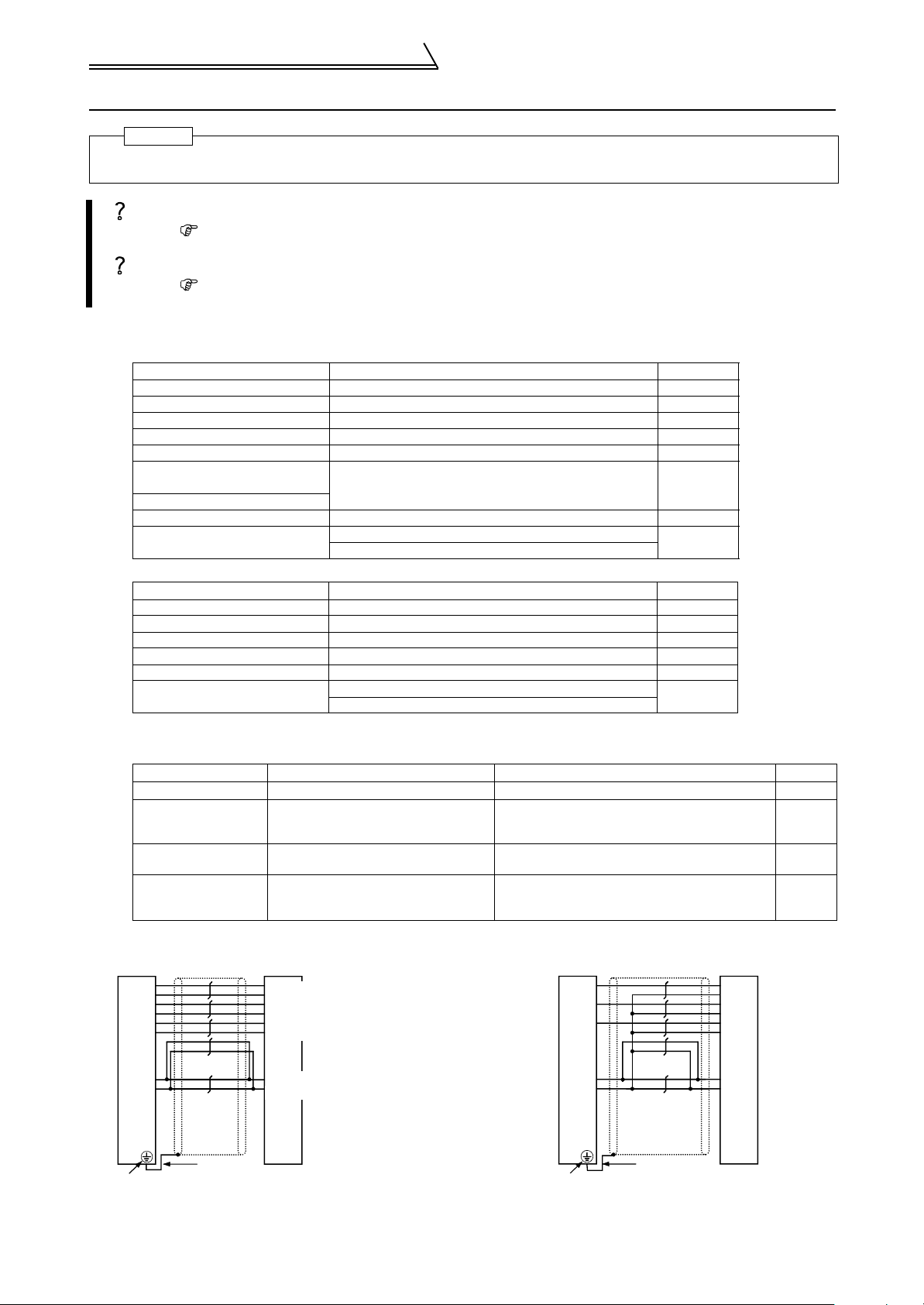
1.5.1 Encoder cable and encoder setting
(1) Encoder specification check items
Item Specification Setting Refer to
Resolution 1000 to 4096 Pulse/Rev Setting by Pr. 851 "number of encoder pulses" 10
Power supply voltage 5V, 12V, 24VDC
Output signal form
Output circuit Differential line driver, Complimentary
(2) Wiring example
1) Differential line driver 2) Complimentary
FR-V500 Encoder
PA
PAR
PB
PBR
PZ
PZR
A, B phases (90° phase)
Z phase (1 Pulse/Rev)
A-phase signal output
A-phase inverted signal output
B-phase signal output
B-phase inverted signal output
Z-phase signal output
Z-phase inverted signal output
Encoder power supply jumper connector
on the back of the control terminal
Across OH-SD
Pr. 876 "thermal relay protector input"
Across OH-SD
Pr. 876 "thermal relay protector input"
Switching the position of the jumper connector
on the back surface of the control circuit
terminal block
Switching the position of the jumper connector
on the back surface of the control circuit
terminal block
FR-V500 Encoder
PA
PAR
PB
PBR
PZ
PZR
9
93
93
9
—14
9
A
B
C
D
F
G
PG
SD
2
Inverter ground terminal
Inverter earth (groun d) terminal
2mm
Power suppoly terminal
Power supply ground terminal
Power supply earth (groun d) terminal
N
PG
SD
2
Inverter ground terminal
Inverter earth (ground) terminal
2mm
S
R
8
Motor
(3) Encoder cable gauge (Cable fabrication specification)
Wiring Distance
0 to 10m (0 to 32.81feet) 2 parallels or more
10 to 20m (32.81 to 65.62feet) 4 parallels or more
20 to 100m (65.62 to 328.08feet) 6 parallels or more
Wiring 0.2mm
Cables
2
(4) Cable stresses
(1) The way of clamping the cable must be fully considered so that flexing stress and cable's own weight stress
are not applied to the cable connection.
(2) In any application where the motor moves, do not subject the cable to excessive stress.
(3) Avoid any probability that the cable sheath might be cut by sharp chips, rubbed by a machine corner or tram-
pled over by workers or vehicles.
(4) When mounting the encoder on a machine where the motor will move, the flexing radius should be as large as
possible.
CAUTION
Please contact the cable manufacturer for the number of cable flexes and cable stress due to the flexing
radius.
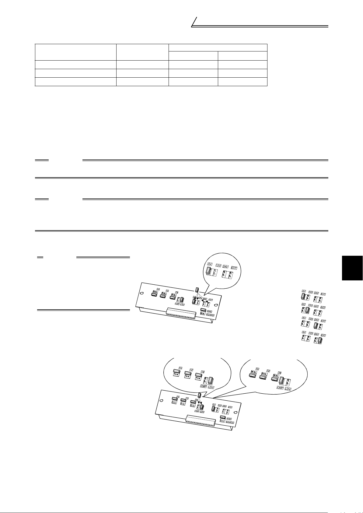
(5) Setting the power supply specification of the encoder and pulse output type
Using larger gauge cable
mm
0.4mm
0.75mm
1.25mm
2
2
2
2
AWG
26 or more
21 or more
16 or more
CAUTION
Make setting correctly.
Fitting the jumper connector to the position exceeding the power specification results in an encoder
failure. Fitting the jumper connector to the position below the power specification results in an encoder
malfunction.
Switch the position of the jumper connector on the back surface of the control circuit terminal block according to the
encoder specification. (Refer to page 16 for removal and installation of the control circuit terminal block.)
CAUTION
• Jumper connector for the
encoder power supply
The jumper connector is fitted
to 5V when shipped from the
factory. Switch its position
according to power supply
specification.
Jumper connector encoder
output circuit
The jumper connector is fitted to
Differential line driver (LDV)
Terminating resistance
Power supply voltage is 5.5V
Power supply voltage is 12V
Power supply voltage is 24V
Power supply voltage is external
Complimentary (CMP)
Terminating resistance
differential line driver (LDV) when
shipped from the factory. Switch its
position according to output circuit.
1
WIRING
9
Motor
0
)
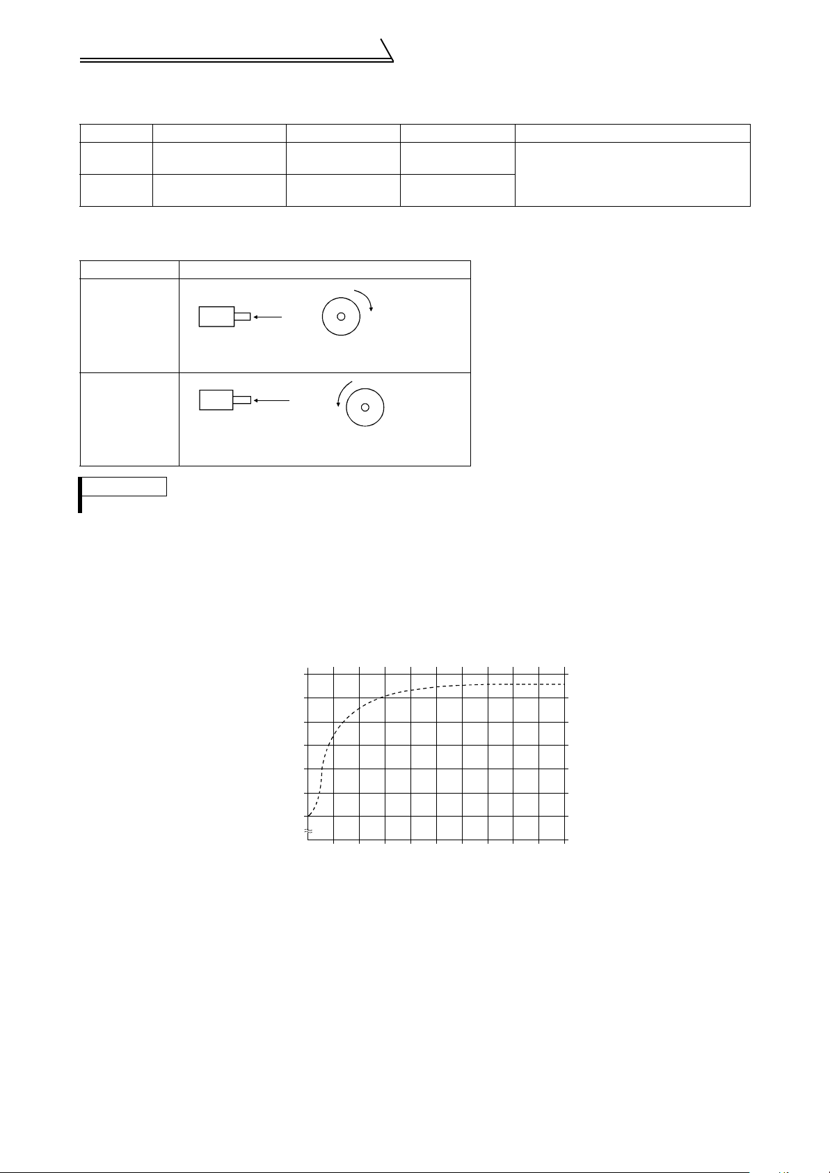
(6) Setting the number of encoder pulses and encoder rotation direction
Set the following parameters according to the encoder specification.
Parameter Name Factory Setting Setting Range Remarks
851
852
Number of encoder
pulses
Encoder rotation
direction
The rotation direction of the encoder is displayed on the operation status indication (FWD,
REV) of the operation panel.
Pr. 852 Setting Rotation direction of the encoder
1024 0 to 4096
10, 1
These are extended mode parameters. Set
"1" in Pr. 160 "extended function selection"
CW
0
1
(factory setting)
A
Encoder
Forward rotation is clockwise rotation
when viewed from A.
CCW
AA
Encoder
Forward rotation is counterclockwise rotation
when viewed from A.
REMARKS
• The number of encoder pulses should be between 1000 and 4096.
1.5.2 Inverter-driven 575V class motor
In the PWM type inverter, a surge voltage attributable to wiring constants is generated at the motor terminals.
Especially for a 575V class motor, the surge voltage may deteriorate the insulation.
200
150
100%
Voltage at a motor terminal (%)
0
10 20 30 40 50 60 70 80 90 10
Motor wiring length (m
Surge voltage at a motor terminal by motor wiring length (reference)
When the 575V class motor is driven by the inverter, consider the following measures:
Measures
(1) Insulation-enhanced motor
Select an insulation-enhanced motor. Many motor manufacturers sell motors with insulation systems designed
to withstand the stress imposed by PWM inverters.
(2) AC reactor
For added protection, install an AC reactor on the inverter output.
10
Connection of stand-alone option units
1.6 Connection of stand-alone option units
The inverter accepts a variety of stand-alone option units as required.
Incorrect connection will cause inverter damage or accident. Connect and operate the option unit carefully in
accordance with the corresponding option unit manual.
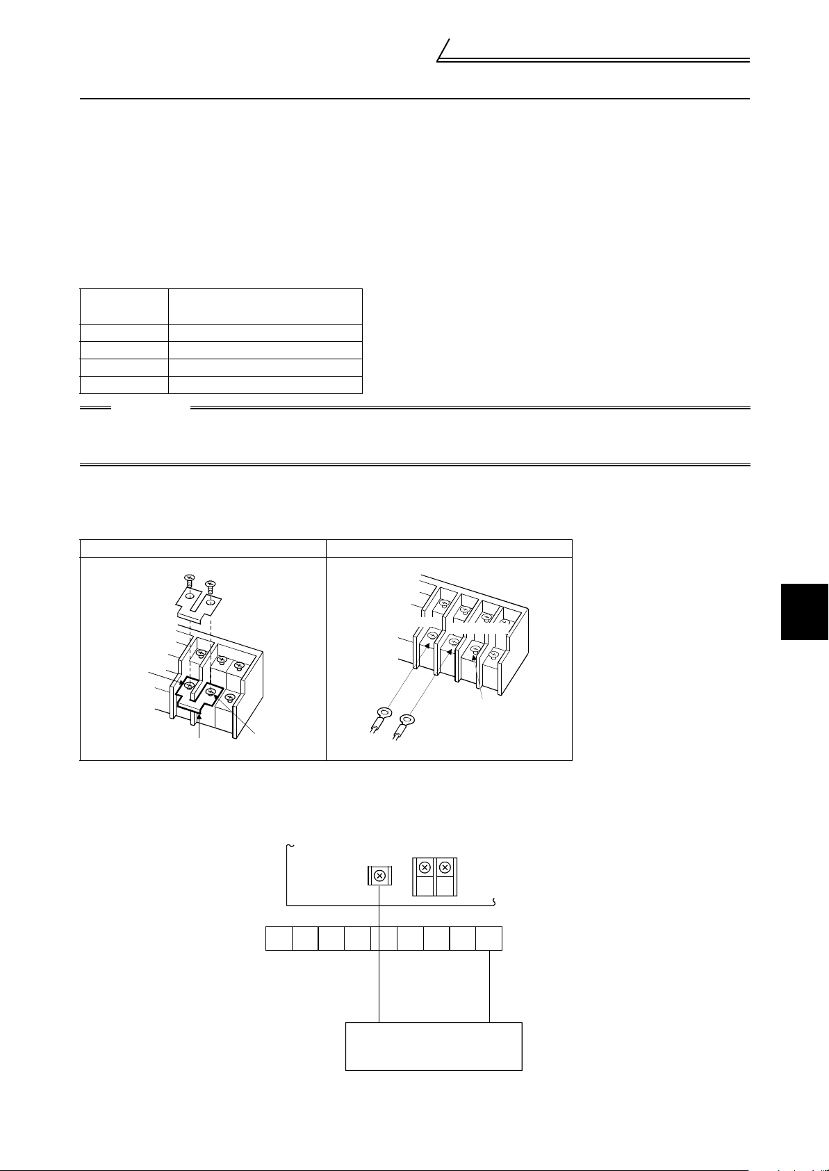
1.6.1 Connection of the external brake resistor
The built-in brake resistor is connected across terminals P and PR. Fit the external brake resistor when the built-in
brake resistor does not have enough thermal capability for high-duty operation. At this time, remove the jumper from
across terminals PR-PX and connect the external brake resistor across terminals P-PR.
The external brake resistor should be as listed in the following table. Selected the rated power of the brake resistor
according to the brake duty. (The rated power indicated below assumes that the brake resistor duty is 10%)
Inverter
capacity
2.2K 350Ω (500W)
3.7K 200Ω (800W)
7.5K 110Ω (1600W)
15K 55Ω (3200W)
Brake resistance specification
(wattage at 10% ED)
CAUTION
1. The brake resistor connected should only be the dedicated brake resistor.
2. The jumper across terminals PR-PX (7.5K or less) must be disconnected before connecting the
external brake resistor. A failure to do so may damage the inverter.
Model ..... FR-V560-2.2K, 3.7K, 7.5K-NA
1)Remove the screws in terminals PR and PX and remove the jumper
2)Connect the brake resistor across terminals P and PR. (The jumper should remain disconnected.)
1) Removal of jumper 2) Connection of brake resistor
Terminal P
Terminal PR
Terminal PR
1
Jumper
Terminal PX
Model ..... FR-V560-15K-NA
1) Connect the brake resistor across terminals P and PR.
PR
V
U
W
External brake resistor
R1
Terminal PX
S1
Power supply terminal
block for control circuit
P1
NPRST
WIRING
11
Connection of stand-alone option units
M
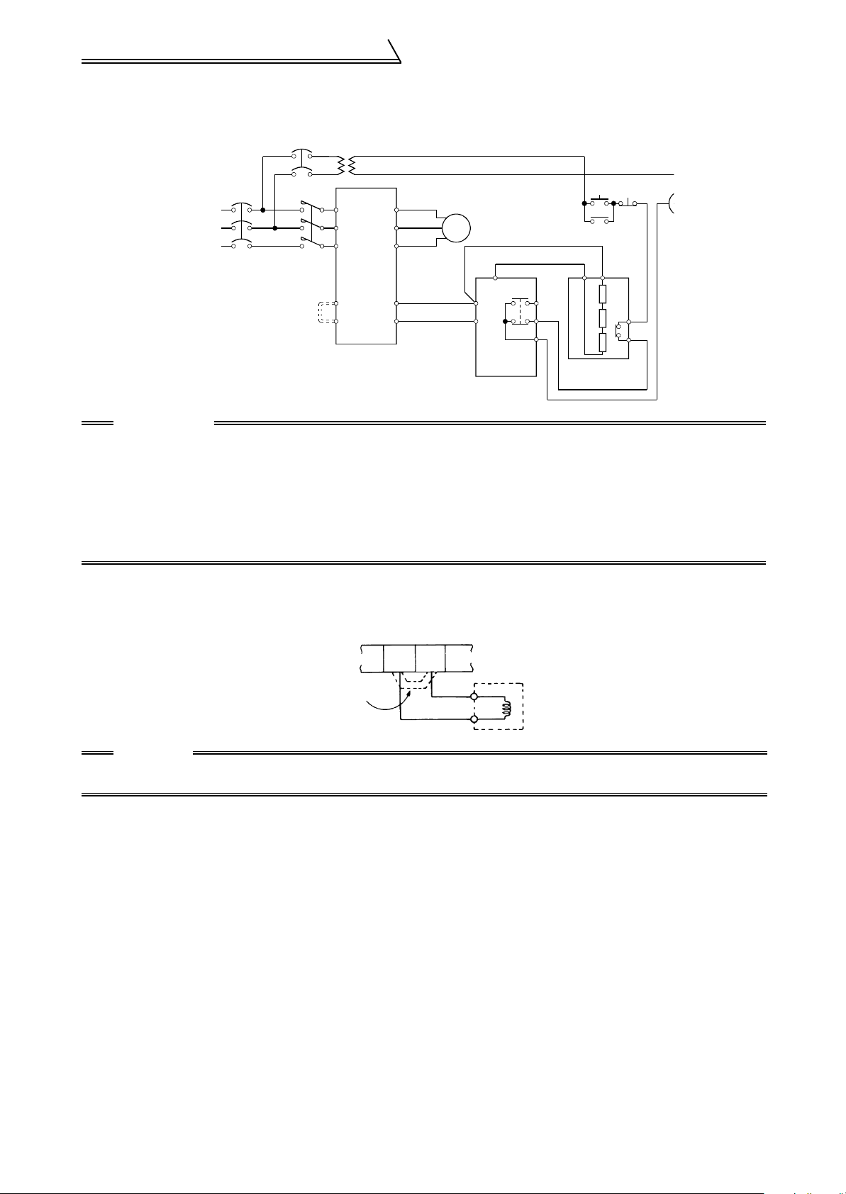
1.6.2 Connection of the brake unit (FR-BU-C)
Connect the optional FR-BU-C brake unit as shown below to improve the braking capability during deceleration.
T (Caution 4)
ON
OFF
MC
PPR
TH1
THS TH2
Resistor unit
FR-BR-C
Power
supply
Remove
jumper.
MC
R
S
T
Inverter
PR
PX
U
V
W
P
N
Motor
IM
PR
P/+
N/-
Brake unit
FR-BU-C
HA
HB
HC
CAUTION
1. Connect the inverter terminals (P, N) and FR-BU-C brake unit terminals so that their terminal signals
match with each other. (Incorrect connection will damage the inverter.) For the 7.5K or less model, the
jumper across terminals PR-PX must be removed.
2. The wiring distance between the inverter, brake unit and resistor unit should be within 5m (16.40
feet). If twisted wires are used, the distance should be within 10m (32.80 feet).
3. If a transistor in the brake unit should become faulty, the resistor can be unusually hot. Therefore,
install a magnetic contactor on the inverter's power supply side to shut off a current in case of fault.
4. Install a voltage-reducing transformer.
1.6.3 Connection of the power factor improving DC reactor
When using the power factor improving DC reactor, connect it between terminals P1-P. In this case, the jumper
connected across terminals P1-P must be removed. Otherwise, the reactor will not exhibit its function.
P1
P
P/{
Remove
the jumper.
CAUTION
1. The wiring distance should be within 5m (16.40 feet).
2. The size of the cables used should be equal to or larger than that of the power supply cables (R, S, T).
12

1.7 Control circuit terminal specifications
1.7.1 Specification of control circuit terminal
Control circuit terminal specifications
Ty pe
Input signals
Terminal
Symbol
STF
STR
DI1 to DI4
OH
Contact input
RES Reset
SD
PC
10E
2
3
Speed setting
1
5
Terminal Name Description Rated Specifications
Forward rotation
start
Reverse rotation
start
Digital input
terminals 1 to 4
Thermal protector
input
Contact input
common (sink)
24VDC power
supply and
external transistor
common, contact
input common
(source)
Speed setting
power supply
Speed setting
(voltage)
Torque setting
terminal
Multi-function
setting terminal
Speed setting
common, Analog
signal output
common
Turn on the STF signal to start
forward rotation and turn it off to
stop.
Turn on the STR signal to start
reverse rotation and turn it off to
stop.
The terminal function varies with
the input terminal function
selection (Pr. 187) setting.
Refer to page 163 for details.
The terminal functions vary with the input terminal
function selection (Pr. 180 to Pr. 183) settings. Refer to
page 163 for details.
Temperature sensor terminal input for motor overheat
protection.
OHT error occurs when terminals OH and SD are open.
Used to reset the protective circuit activated. Turn on
the RES signal for more than 0.1s, then turn it off.
Recover about 1s after reset is cancelled.
Contact input common terminal. Common output
terminal for 24VDC 0.1A power supply (PC terminal).
Isolated from terminals 5 and SE.
When connecting a transistor output (open collector
output) such as a programmable controller, connect the
external power supply common for transistor output to
this terminal to prevent a malfunction caused by a sneak
current. PC-SD can be used as a 24VDC and 0.1A
power supply. Note that a sneak current may not be
prevented in this case. When source logic has been
selected, this terminal serves as a contact input
common.
Used as power supply when connecting volume for
speed setting (torque setting) from outside of the
inverter. (terminal 5 is a common terminal)
By entering 0 to 10VDC, the maximum output speed is
reached at 10V and I/O are proportional.
Acts as a torque setting signal for torque control or as a
torque restriction signal for speed control or position
control.
Acts as an input terminal for the external analog-based
torque bias function.
0 to ±10VDC input
Since this is a multi-function selection terminal, its
function varies with the Pr.868 "No. 1 terminal function
assignment" setting. Refer to page 195 for details.
0 to ±10VDC input
Common terminal for speed setting signal (terminal 2, 1
or 3) or DA1 and DA2.
Isolated from terminals SD and SE. Do not ground.
When the STF and
STR signals are
turned on
simultaneously, the
stop command is
given.
Input resistance 4.7kΩ
Voltage at opening 21 to
27VDC
Current at short-circuited
4 to 6mADC
Control by open collector
output or 0V contact
signal
Input resistance 150kΩ
Voltage at opening 21 to
27VDC
Current at short-circuited
140 to 180mADC
Isolate by photocoupler
Input resistance 4.7kΩ
Voltage at opening 21 to
27VDC
Current at short-circuited
4 to 6mADC
Control by open collector
output or 0V contact
signal.
—
Voltage range 18 to 26
VDC
Permissible load current
0.1A
10VDC±0.4V
Permissible load current
10mA
Input resistance
10kΩ±1kΩ
Permissible maximum
voltage 20VDC
—
1
WIRING
13

Control circuit terminal specifications
Ty pe
Input signals
Output signals
Communication
Terminal
Symbol
PA
PAR
PB
PBR
PZ
Encoder signal
PZR
PG
SD
A, B, C Alarm output
Contact
DO1 to
DO3
Open
collector
SE
DA1, DA2
Analog
5
— PU connector
RS-485
Terminal Name Description Rated Specifications
A-phase signal
input terminal
A-phase inverted
signal input
terminal
B-phase signal
input terminal
B-phase inverted
signal input
terminal
Z-phase signal
input terminal
Z-phase inverted
signal input
terminal
Encoder power
supply terminal
(Positive side)
Contact input
common (sink),
Power supply
ground terminal
Digital output
terminals 1 to 3
Open collector
output common
Analog signal
output
Analog signal
output common
* Not output during inverter reset.
Differential line receiver
input (AM26LS32
equivalent) or
complimentary input
Differential line receiver
input (AM26LS32
equivalent)
Differential line receiver
input (AM26LS32
A-, B- and Z-phase signals are input from the encoder.
Power supply for encoder. You can switch the power
supply between 5, 12 and 24VDC. Can be switched to
the external power supply.
(Refer to the instruction manual (basic) for the
switchover method.)
Common terminal for contact input or encoder power
supply.
Isolated from terminals 5 and SE.
Do not ground.
Switch-over contact output indicating that the output has
been stopped by the inverter protective function.
230VAC 0.3A, 30VDC 0.3A. Alarm: discontinuity across
B-C (continuity across A-C), normal: continuity across
B-C (discontinuity across A-C).
The terminal function varies with the output terminal
function selection (Pr. 195) setting.
Refer to page 165 for details.
The terminal functions vary with the output terminal
function selection (Pr. 190 to Pr. 192) settings. Refer to
page 165 for details.
Common terminal for terminals DO1, DO2 and DO3.
Isolated from terminals SD and 5.
One selected from monitoring items, such as the speed,
is output.
The output signal is proportional to the magnitude of the
corresponding monitoring item.
Common terminal for DA1 and DA2. Isolated from terminals SD and SE. Do not
ground.
With the PU connector, communication can be made
through RS-485.
• Conforming standard : EIA Standard RS-485
• Transmission format : Multidrop link system
• Communication speed : Maximum. 19200bps
• Overall length : 500m
*
equivalent) or
complimentary input
Differential line receiver
input (AM26LS32
equivalent)
Differential line receiver
input (AM26LS32
equivalent) or
complimentary input
Differential line receiver
input (AM26LS32
equivalent)
5.5VDC 350mA
12VDC 150mA
24VDC 80mA
Power supply common
Contact output
Permissible contact
230VAC 0.3A
30VDC 0.3A
Open collector output
Permissible load 24VDC
0.1A
—
0 to ±10VDC
Permissible load current
1mA
Resolution 12 bit
load impedance
10kΩ or more
14
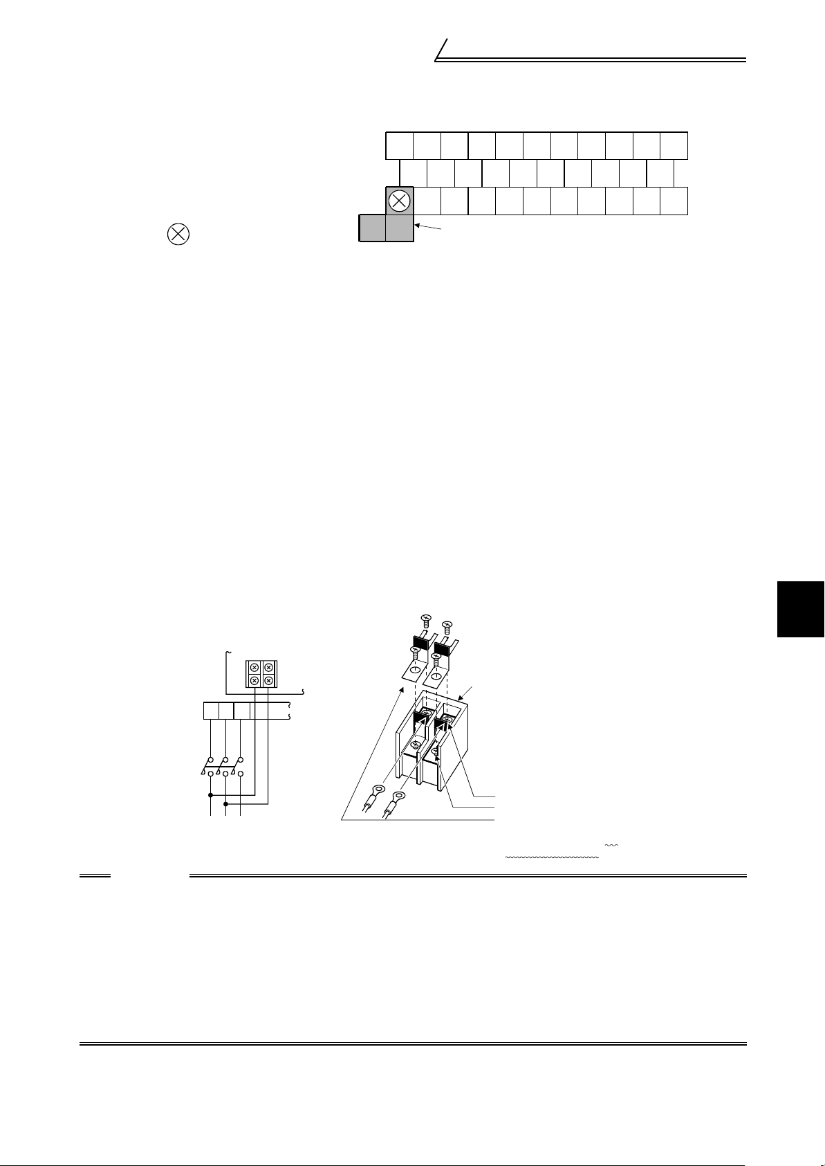
Control circuit terminal specifications
1.7.2 Control circuit terminal layout
Terminal screw size : M3.5
Tightening torque : 1.2N·m
When connecting three or more control cables
to the terminal 5, connect the accessory
terminal 5 dedicated L-shaped jumper to the
terminal 5.
In this case no cable should be connected to
the screw in the part.
BDO1DO2DI4
A
10E
5
5
C
2 DA1 SE PZ PZR PG RES
3 1 PA PAR PB PBR SD OH
DO3
DA2
Jumper
DI3 DI2 DI1
STR
STF
PC
SD
1.7.3 Wiring instructions
1) Terminals 5, SD and SE are common to the I/O signals and isolated from each other. Do not ground these terminals. Avoid connecting the terminal SD and 5 and the terminal SE and 5.
2) Use shielded or twisted cables for connection to the control circuit terminals and run them away from the main
and power circuits (including the 200V relay sequence circuit).
3) Since the control circuit input signals are micro currents, use two or more parallel micro signal contacts or a
twin contact to prevent a contact fault.
4) It is recommended to use the cables of 0.75mm
cable gauge used is 1.25mm
2
or more, the front cover may be lifted when there are many cables running or the
cables are run improperly, resulting in an operation panel or parameter unit contact fault.
5) The maximum wiring length should be 30m (98.43 feet).
2
gauge for connection to the control circuit terminals. If the
1.7.4 Connecting the control circuit to a power supply separately from the main circuit
If the magnetic contactor (MC) in the inverter power supply is opened when the protective circuit is operated, the
inverter control circuit power is lost and the alarm output signal cannot be kept on. To keep the alarm signal on
terminals R1 and S1 are available. In this case, connect the power supply terminals R1 and S1 of the control circuit
to the primary side of the MC.
<Connection procedure>
R1
S1
Power supply terminal
block for control circuit
RST
MC
Main power supply
CAUTION
1. When the main circuit power (R, S, T) is on, do not switch off the control power (terminals R1, S1).
Otherwise the inverter may be damaged.
2. When using a separate power supply, the jumpers across R-R1 and S-S1 must be removed.
Otherwise the inverter may be damaged.
3. For a different power supply system which takes the power of the control circuit from other than the
primary side of the MC, the voltage should be equal to the main circuit voltage.
4. The power supply cables must not be connected to the lower terminals. If connected, the inverter
may be damaged.
5. Entering the start signal with power supplied to only the R1 and S1 terminals will result in an error
display (E.OC1).
Power supply terminal
block for control circuit
1) Loosen the upper screws.
2) Remove the lower screws.
3) Pull out an d remov e the ju mper.
4) Connect the separate power supply
cables for control circuit to the
upper terminals (R1, S1). (Note 4)
1
WIRING
15
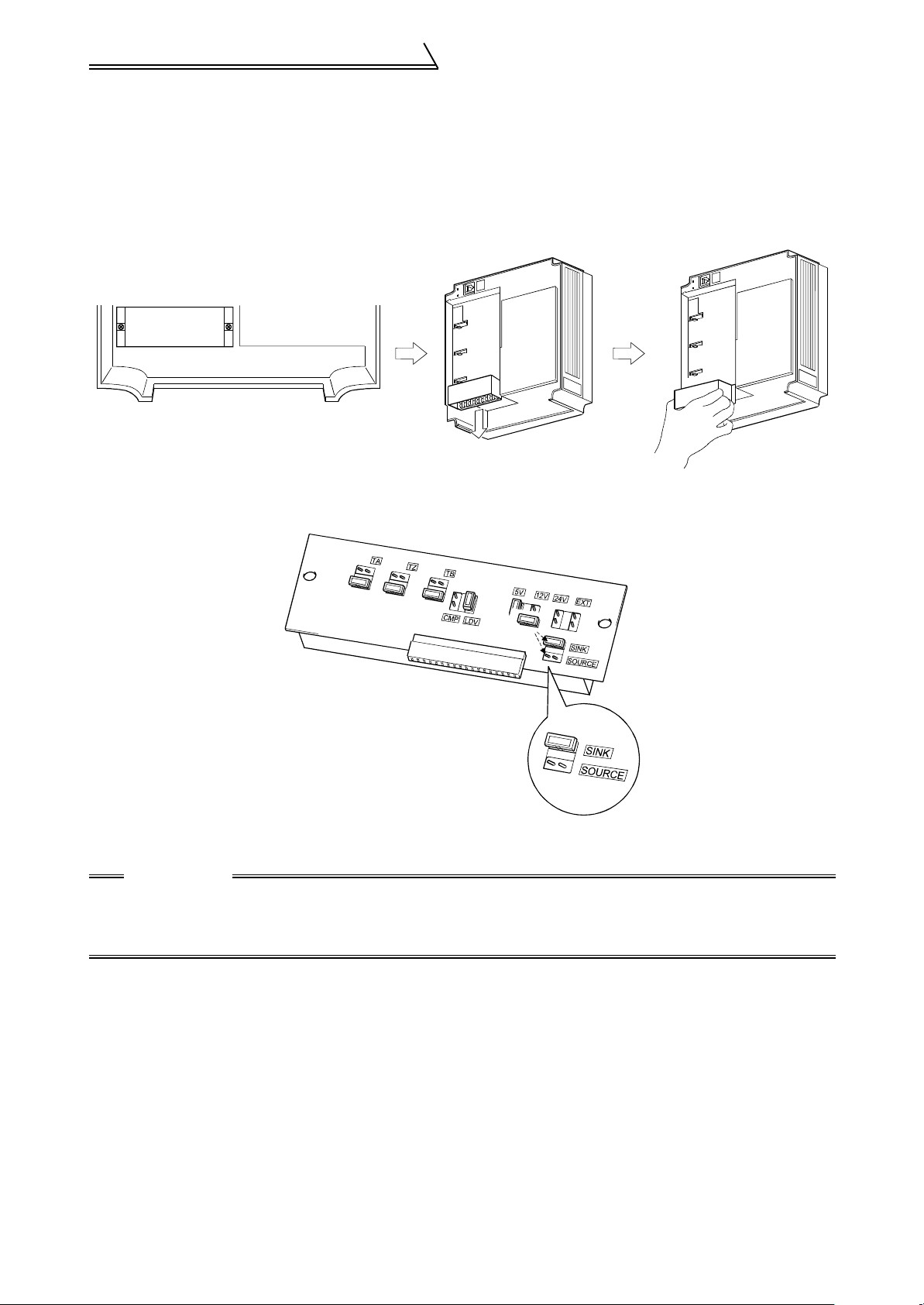
Control circuit terminal specifications
1.7.5 Changing the control logic
The input signals are factory set to sink logic (SINK).
To change the control logic, the jumper connector on the back of the control circuit terminal block must be moved to
the other position.
(The output signals may be used in either the sink or source logic independently of the jumper connector position.)
1) Loosen the two mounting screws in both ends of the control circuit terminal block. (The screws cannot be
removed.) Pull down the terminal block from the back of the control circuit terminals.
2) Fit the jumper connector from the sink logic (SINK) position on the back surface of the control circuit terminal
block to the source logic (SOURCE) position to change to the source logic.
3) Using care not to bend the pins of the inverter's control circuit connector, reinstall the control circuit terminal
block and fix it with the mounting screws.
CAUTION
1. Make sure that the control circuit connector is fitted correctly.
2. While power is on, never disconnect the control circuit terminal block.
3. The sink-source logic change-over jumper connector must be fitted in only one of those positions. If
it is fitted in both positions at the same time, the inverter may be damaged.
16
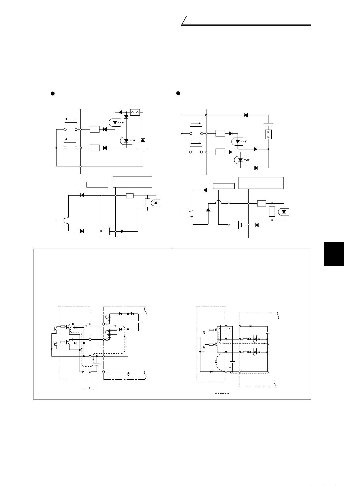
Control circuit terminal specifications
r
4) Sink logic type and source logic type
• The sink logic type is a logic where a signal turns on when a current flows out of the corresponding signal
input terminal.
Terminal SD is common to the contact input signals. Terminal SE is common to the open collector output signals.
• The source logic type is a logic where a signal turns on when a current flows into the corresponding signal
input terminal.Terminal PC is common to the contact input signals. Terminal SE is common to the open collector output signals.
Current flow concerning the RUN signal
when sink logic is selected
Sink logic
Current
STF
STR
SD
R
R
Inverter
RUN
SE
24VDC
Sink connector
DC input (sink type)
<Example : AX40>
1
R
9
R
When using an external power supply for transistor output
• Sink logic type
• Source logic type
Using terminal PC as a common terminal prevents a
malfunction caused by undesirable current. (Do not
connect terminal SD of the inverter with terminal 0V
of the external power supply. When using terminals
PC-SD as a 24VDC power supply, do not install a
power supply in parallel in the outside of the inverter.
Doing so may cause a malfunction due to undesirable current.)
Current flow concerning the RUN signal
when source logic is selected
Source logic
PC
Current
STF
STR
R
R
Inverter
RUN
SE
DC input (source type)
<Example : AX80>
1
9
24VDC
Source
connecto
R
R
Use terminal SD as a common to prevent a malfunction caused by undesirable current.
1
WIRING
transistor
output module
1
2
9
9
10
STF
STR
24VDC
Current flow
PC
SD
InverterAY40 type
24VDC
(SD)
AY80 type
transistor
output module
9
1
2
10
PC
STF
STR
24VDC
SD
Current flow
Inverter
24VDC
(SD)
17

Precautions for use of the vector inverter
1.8 Precautions for use of the vector inverter
The FR-V500 series is a highly reliable product, but incorrect peripheral circuit making or operation/handling
method may shorten the product life or damage the product.
Before starting operation, always recheck the following items.
(1) Use insulation-sleeved crimping terminals for the power supply and motor cables.
(2) Power must not be applied to the output terminals (U, V, W) of the inverter. Otherwise the inverter will be damaged.
(3) After wiring, wire off-cuts must not be left in the inverter.
Wire off-cuts can cause an alarm, fault or malfunction. Always keep the inverter clean.
When drilling mounting holes in a control box or the like, use care not to allow chips etc. to enter the inverter.
(4) Wire the cables of the recommended size to make a voltage drop 2% or less.
If the wiring distance is long between the inverter and motor, a main circuit cable voltage drop will cause the
motor torque to decrease especially at the output of a high frequency.
Refer to page 7 for the recommended wire sizes.
(5) The overall wiring length should be 100m (328.08 feet) maximum.
Especially for long distance wiring, the high-response current restriction function may be reduced or the
equipment connected to the secondary side may malfunction or become faulty under the influence of a
charging current due to the stray capacity of the wiring. Therefore, note the overall wiring length.
(6) Electromagnetic wave interference
The input/output (main circuit) of the inverter includes harmonic components, which may interfere with the
communication devices (such as AM radios) used near the inverter. In this case, install the radio noise filter (for use
on the input side only) or line noise filter to minimize interference.
(7) Do not install a power factor correction capacitor, surge suppressor or radio noise filter on the output side of the
inverter.
This will cause the inverter to trip or the capacitor and surge suppressor to be damaged. If any of the above devices is
installed, immediately remove it. (When the radio noise filter is connected, switching power off during motor operation
may result in E. UVT. In this case, connect the radio noise filter in the primary side of the magnetic contactor.)
(8) When rewiring after operation, switch power off, wait for more than 10 minutes, and then make sure that the
voltage is zero using a tester, etc. For some time after power-off, there is a dangerous voltage in the capacitor.
(9) A short circuit or ground fault in the inverter output side may damage the inverter modules.
• Fully check the insulation resistance of the circuit prior to inverter operation since repeated short circuits
caused by peripheral circuit inadequacy or an ground fault caused by wiring inadequacy or reduced motor
insulation resistance may damage the inverter modules.
• Fully check the to-ground insulation and inter-phase insulation of the inverter secondary side before power-on.
Especially for an old motor or use in hostile atmosphere, securely check the motor insulation resistance etc.
(10) Do not use the inverter power supply side magnetic contactor to start/stop the inverter.
Always use the start signal (turn on/off terminals STF, STR-SD) to start/stop the inverter. (Refer to page 21.)
(11) Across the P and PR terminals, connect only an external regenerative brake discharge resistor.
Do not connect a mechanical brake.
(12) Do not apply a voltage higher than the permissible voltage to the inverter I/O signal circuits.
Application (contact) of a voltage higher than the permissible voltage to the inverter I/O signal circuits or
opposite polarity may damage the I/O devices. Especially check the wiring to prevent the speed setting
potentiometer from being connected incorrectly to short terminals 10E-5.
(13) Use of single-phase power supply
Do not use single-phase power input.
(14) Connect the encoder to the backlash-free motor shaft.
Capacity (VA) of separate power supply
The capacity is 60VA or more for 15kW (20HP) or less and 80VA for 22kW (30HP) to 55kW (75HP) when separate
power is supplied from R1, S1.
18

Others
1.9 Others
1.9.1 Leakage currents and countermeasures
Leakage currents flow through static capacitances existing in the inverter I/O wiring and motor. Since their values
depend on the static capacitances, carrier frequency, etc., take the following measures.
(1) To-ground leakage currents
Leakage currents may flow not only into the inverter's own line but also into the other lines through the ground
cable, etc.
These leakage currents may operate ground leakage breakers and ground leakage relays unnecessarily.
Countermeasures
• When the carrier frequency setting is high, decrease the carrier frequency (Pr. 72) of the inverter.
Note that motor noise increases. Selection of Soft-PWM (Pr. 240) will make it unoffending.
• Ground leakage breakers designed for harmonics and surges can be used in the inverter's own line and other
lines to perform operation with the carrier frequency high (with low noise).
(2) Line-to-line leakage currents
Harmonics of leakage currents flowing in static capacitances between the inverter output cables may operate the
external thermal relay unnecessarily. When the wiring length is long (50m (164.04 feet) or more) for the smallcapacity model (7.5kW (10HP) or less), the external thermal relay is likely to operate unnecessarily because the
ratio of the leakage current to the rated motor current increases.
Line-to-line leakage current data example
Motor capsity
(kW (HP))
2.2 (3) 8.1 1200 1770
Rated Motor
Current(A)
Power supply
Wiring length
50m (164.04 feet)
Leakage Current (mA)
100m (328.08 feet)
NFB
Inverter
Line-to-Line Leakage Current Path
Thermal relay
Wiring length
Line static capacitances
• Motor SF-JR 4P
• Carrier frequency: 14.5KHz
•Cable :2mm
• Cab tyre cable
Motor
IM
2
4-core
Measures
• Use the electronic thermal relay function (Pr. 9) of the inverter.
• Decrease the carrier frequency. Note that motor noise increases. Selection of Soft-PWM (Pr. 240) will make it
unoffending.
Using a temperature sensor to directly detect the motor temperature is recommended to ensure that the motor
is protected against line-to-line leakage currents.
Installation and selection of no-fuse breaker
Install a no-fuse breaker (NFB) on the power receiving side to protect the wiring of the inverter primary side.
Select the NFB according to the power supply side power factor (which depends on the power supply voltage,
output frequency and load). Especially for a completely electromagnetic NFB, one of a slightly large capacity
must be selected since its operation characteristic varies with harmonic currents. (Check it in the data of the
corresponding breaker.) As a ground leakage breaker, use the Mitsubishi ground leakage breaker designed for
harmonics and surges.
1
WIRING
19
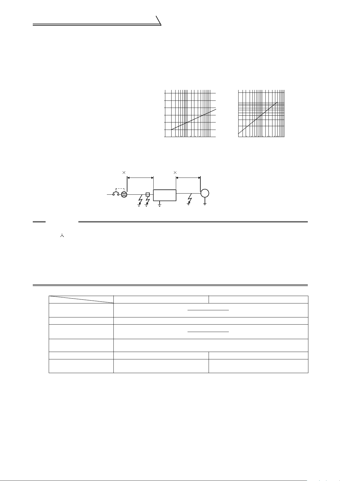
Others
(3) Selection of rated sensitivity current of ground leakage breaker
When using the ground leakage breaker with the inverter circuit, select its rated sensitivity current as follows,
independently of the PWM carrier frequency.
• Breaker for harmonic and surge
Rated sensitivity current
I∆n ≥10
× (Ig1 + lgn + Ig2 + Igm)
• Standard breaker
Rated sensitivity current
I∆n ≥10
× {Ig1 + Ign + 3 × (Ig2 + Igm)}
Ig1, Ig2: Leakage currents of cable path
during commercial power supply operation
Ign *:Leakage current of noise filter on
inverter input side
Igm:Leakage current of motor during
commercial power supply operation
<Example>
Leakage Current Example of Cable
Path per 1km during Commercial
Power Supply Operation When CV
Cable Is Routed in Metal Conduit
(200V 60Hz)
120
100
80
60
40
20
Leakage current (mA)
0
23.5
8142230386080
5.5
Cable size (mm
150
100
2
) Motor capacity (kW)
Leakage Current Example of
3-Phase Induction Motor during
Commercial Power Supply Operation
(200V 60Hz)
2.0
1.0
0.7
0.5
0.3
0.2
Leakage current (mA)
0.1
1.5 3.7
7.5 15 2211373055
5.5 18.5
2.2
45
2mm
NV
2
5m (16.40feet)
Noise
filter
Ig1 Ign Ig2 Igm
2mm
Inverter
2
70m (229.65feet)
3
φ
IM
200V1.5kW
CAUTION
• Install the NV on the primary (power supply) side of the inverter.
• In the connection neutral point grounding system, the sensitivity current is purified against an
ground fault in the inverter secondary side. Grounding must conform to the requirements of national
and local safety regulations and electrical codes. (JIS, NEC section 250, IEC 536 class 1 and other
applicable standards)
• When the breaker is installed on the secondary side of the inverter, it may be unnecessarily operated
by harmonics if the effective value is less than the rating.
In this case, do not install the breaker since the eddy current and hysteresis loss will increase, leading
to temperature rise.
* Note the leakage current value of the noise filter installed on the inverter input side.
Breaker for Harmonic and Surge Standard Breaker
Leakage current Ig1 (mA) 20 ×
5m(16.40feet)
1000m(3280feet)
= 0.10
Leakage current Ign (mA) 0 (without noise filter)
Leakage current Ig2 (mA) 20 ×
Motor leakage current Igm
(mA)
70m(229.65feet)
1000m(3280feet)
0.16
= 1.40
Total leakage current (mA) 1.66 4.78
Rated sensitivity current
( ≥Ig × 10)
(mA)
30 100
20
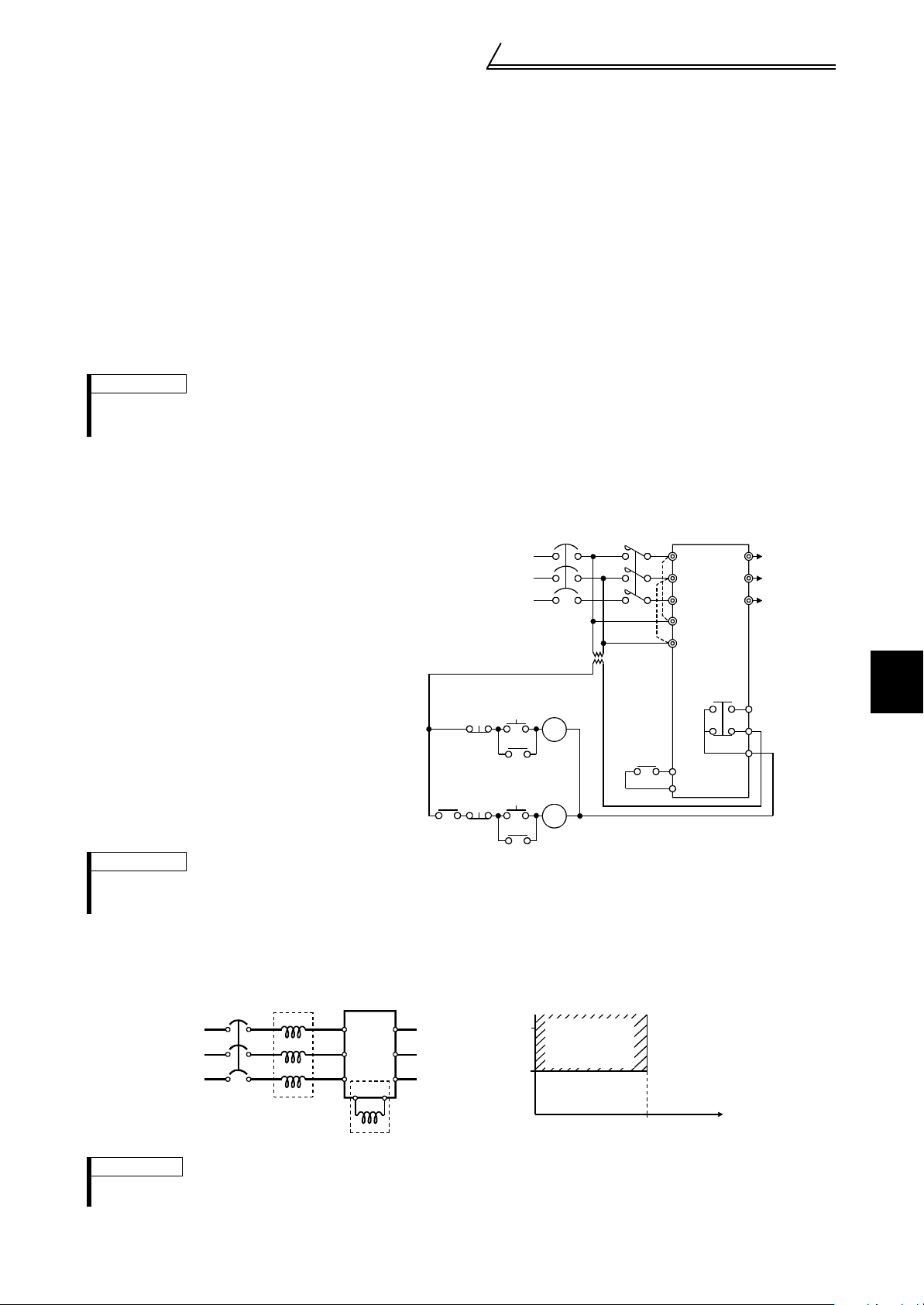
Others
r
1.9.2 Power off and magnetic contactor (MC)
(1) Inverter primary side magnetic contactor (MC)
On the inverter primary side, it is recommended to provide an MC for the following purposes.
(Refer to page 3 for selection.)
1) To release the inverter from the power supply when the inverter protective function is activated or the drive
becomes faulty (e.g. emergency stop operation)
When cycle operation or heavy-duty operation is performed with an optional brake resistor connected, overheat
and burnout of the electrical-discharge resistor can be prevented if a regenerative brake transistor is damaged
due to insufficient heat capacity of the electrical-discharge resistor and excess regenerative brake duty.
2) To prevent any accident due to an automatic restart at restoration of power after an inverter stop made by a
power failure
3) To rest the inverter for an extended period of time
The control power supply for inverter is always running and consumes a little power. When stopping the
inverter for an extended period of time, powering off the inverter will save power slightly.
4) To separate the inverter from the power supply to ensure safe maintenance and inspection work
Since the MC on the inverter primary side is used for the above purposes, they correspond to the standard
duties. Therefore, when making an emergency stop during running, select a JEM1038 class AC3 MC for the
inverter input side currents.
REMARKS
The MC may be switched on/off to start/stop the inverter. However, since repeated inrush currents at power-on will shorten the
life of the converter circuit (switching life is about 100,000 times), frequent starts and stops must be avoided. Turn on/off the
inverter start controlling terminals (STF, STR) to run/stop the inverter.
(2) Handling of secondary side magnetic contactor
In principle, do not provide a magnetic contactor between the inverter and motor and switch it from off to on
during operation. If it is switched on during inverter operation, a large inrush current may flow, stopping the
inverter due to overcurrent shut-off. When an MC is provided for switching to the commercial power supply, for
example, switch it on/off after the inverter and motor have stopped.
Inverter Start/Stop Circuit Example
As shown on the right, always use the start
signal (turn on/off terminals STF, STR-SD) to
start/stop the inverter.
(Refer to page 29.)
Power
supply
Operation ready
ON
OFF
MC
Start/Stop
MC
Operation
OFF
RA
MC
RA
NFB
MC
*1
Inverter
U
V
To moto
W
A
B
C
R
S
T
R1
S1
T
RA
STF(STR)
SD
1
WIRING
REMARKS
*1. Connect the power supply terminals R1 and S1 to the primary side of the MC to hold an alarm signal when the inverter`s
protective circuit is activated. At this time, remove jumpers across terminals R-R1 and S-S1. (For removal of jumpers,
refer to page 15)
1.9.3 Installation of power factor improving reactor
When the inverter is connected near a large-capacity power transformer (1000kVA or more and wiring length 10m (32.80
feet) max.) or when a power capacitor is to be switched over, an excessive peak current may flow in the power input circuit,
damaging the converter circuit. To prevent this, always install the power factor improving reactor.
AC reactor
NFB
R
Power
supply
S
TZ
REMARKS
* When connecting the DC reactor, remove the jumper across terminals P-P1. The wiring length between the DC reactor and
inverter should be 5m (16.4feet) maximum and minimized. Use the same wire size as that of the power supply wire (R, S, T).
Inverter
X
R
Y
S
T
PP1
DC reactor (*)
(kVA)
Power factor
improving reactor
installation range
0
Wiring length (m)
10
U
V
W
1500
1000
Power supply
equipment capacity
21
 Loading...