

Mitsubishi FR-V520-37K, FR-V540-15K, FR-V520-55K, FR-V520-7.5K, FR-V520-11K Instruction Manual
...
6
5
4
2
1
3
VECTOR INVERTER
FR-V
500
INSTRUCTION MANUAL (BASIC)
FR-V520-1.5K to 55K
FR-V540-1.5K to 55K
FR-V500
VECTOR INVERTER INSTRUCTION MANUAL (BASIC)
2
1
3
4
5
6
7
Contents
OUTLINE......................................................................................................1
1.1 Basic configuration and connection of peripheral devices........................................2
1.2 Structure...................................................................................................................4
INSTALLATION AND WIRING.....................................................................6
2.1 Installation of the inverter .........................................................................................6
2.2 Connection diagram, PLG cable, PU connector.......................................................7
2.3 Setting the motor ....................................................................................................19
2.4 Precautions for use of the vector inverter...............................................................21
RUN AND OPERATION.............................................................................22
3.1 Checks prior to test run ..........................................................................................22
3.2 Basic operation (Speed setting, run, speed meter adjustment)..............................22
3.3 Names and functions of the operation panel..........................................................26
CONTROL..................................................................................................32
4.1 Speed control operation ........................................................ ...... ....... ...... ....... ...... . 32
4.2 Torque control operation ........................................................................................36
4.3 Position control operation.......................................................................................41
4.4 Control mode switchover timing .............................................................................42
4.5 Easy gain tuning.....................................................................................................43
4.6 Online auto tuning ....................................................................... ....... ...... ....... .......46
4.7 Biases and gains of speed setting terminals
(Pr. 902 to Pr. 905, Pr. 917 to Pr. 920)...................................................................47
PARAMETERS...........................................................................................50
5.1 Function list (Simple mode parameters).................................................................50
5.2 Function list (Extended function parameters).........................................................54
ERRORS AND PROTECTIVE FUNCTIONS..............................................70
6.1 Errors (Alarms) ......................... ...... ...... ....... ...... ....... ...... ....... ...... ....... ....................70
6.2 Correspondences between digital and actual characters.......................................80
6.3 Resetting the inverter ..................................................... ....... ...... ....... ...... ....... ...... .80
6.4 Troubleshooting......................................................................................................82
6.5 Precautions for maintenance and inspection..........................................................93
SPECIFICATIONS .....................................................................................99
Thank you for choosing this Mitsubishi Vector Inverter.
If this is the first time for you to use the FR-V500 series, please read through this Instruction Manual (basic) carefully to use the inverter safely.
When you are going to use the inverter for higher-leveled applications, please request the separately available
FR-V500 Instruction Manual (detailed) [IB(NA)-0600065] from where you purchased the inverter or a Mitsubishi
sales representative.
This Instruction Manual (basic) provides handling information and precautions for use of the equipment.
Please forward this Instruction Manual (basic) to the end user.
This section is specifically about safety matters
Do not attempt to install, operate, maintain or inspect the inverter until you have read through the Instruction
Manual (basic) and app ended do cumen ts car efull y and c an use the equ ipm ent corr ectly. In this Instruction
Manual, the safety instruction levels are classified into "WARNING" and "CAUTION"
.
WARNING
CAUTION
Note that even the CAUTION lev el may lead to a serious cons equence ac cor ding to con ditio ns. Please fo llow the instructions of both levels because they are important to personnel safety.
1. Electric Shock Prevention
Assumes that inco rrect ha ndlin g may c ause h azardou s cond ition s, res ultin g in
death or severe injury.
Assumes that inco rrect ha ndlin g may c ause h azardou s cond ition s, res ultin g in
medium or slight injury, or may cause physical damage only.
WARNING
!Whi le power is on or when the inver ter is running, do not open the front cover. You may get an electric
shock.
!Do not run the inverter wit h the fron t cover remov ed. Otherwi se, you may access the exposed h igh-volt-
age terminals or the charging part of the circuitr y and get an electr ic shock .
!If power is off, do not remove the front cover except for wiring or periodic inspection. You may access the
charged inverter circuits and get an electric shock.
!Before starting wiring or inspection, check that power lamp display is turned off and check for residual volt-
ages with a meter etc. more than 10 minutes after power-off.
!Earth (Ground) the inverter.
!Any person wh o is involv ed in wir ing or inspe ction of this equipment s hould be fu lly compe tent to do the
work.
!Always install the inverter before wiring. Otherwise, you may get an electric shock or be injured.
!Perform setting dial and key operations with dry hands to prevent an electric shock.
!Do not subject the cables to sc ratches, excessive str ess, heavy loads or pinc hing. Otherwise, you may
get an electric shock.
!Do no t change the cooling fan while power is on. It i s dan ger ou s t o c han ge the co oli ng fan whi le powe r is
on.
2. Fire Prevention
CAUTION
!Mount the inverter to incombustible material. Mounting it to or near combustible material can cause a fire.
!If the inverter has become faulty, switch off the inverter power. A continuous flow of large cur rent could
cause a fire.
!Do not connect a resistor directly to the DC terminals P, N. This could cause a fire.
3.Injury Prevention
CAUTION
!Apply only the voltage specified in the instruction manual to each terminal to prevent damage etc.
!Ensure that the cables are connected to the correct terminals. Otherwise damage etc. may occur.
!Always make sure that polarity is correct to prevent damage etc.
!While power is on and for some time after power-off, do not touch the inverter or brake resistor as they are
hot and you may get burnt.
A-1
4. Additional Instructions
Also note the following points to prevent an accidental failure, injury, electric shock, etc.
1) Tra nsportation and installation
CAUTION
!When carrying products, use correct lifting gear to prevent injury.
!Do not stack the inverter boxes higher than the number recommended.
!Ensure that installation position and material can withstand the weight of the inverter.
!Do not operate if the inverter is damaged or has parts missing.
!When carrying the inverter, do not hold it by the front cover or setting dial; it may fall off or fail.
!Do not stand or rest heavy objects on the inverter.
!Check the inverter mounting orientation is correct.
!Prevent screws, wire fragments, other conductive bodies, oil or other flammable substances from entering
the inverter.
!Do not drop the inverter, or subject it to impact
!Use the inverter under the following environmental conditions:
Ambient temperature
Ambient
humidity
Storage
ture
Ambience Indoors (free from corrosive gas, flammable gas, oil mist, dust and dirt)
Environment
Altitude, vibration
*
Temperature applicable for a short time, e.g. in transit.
tempera-
-10°C to +50°C (non-freezing)
90%RH or less (non-condensing)
-20°C to +65°C*
Maximum 1000m above sea level for standard operation.
After that derate by 3% for every extra 500m up to
2500m (91%). 5.9m/s
2
or less (conforming to JIS C 0040)
2) Wiring
CAUTION
!Do not fit capacit ive equipmen t such as power fac tor correction capacitor, radio noise filter or surge sup-
pressor to the output of the inverter.
!The connecti on orien tation of the output cables U, V, W to the motor will affect the direction of rotati on of
the motor.
3) Trial run
CAUTION
!Check all parameters, and ensure that the machine will not be damaged by a sudden start-up.
4) Operation
!When you have chosen the retry function, stay away from the equipment as it will restart suddenly after an
alarm stop.
!The [STOP] key is valid only when the appropriate functi on setting has been made. Prepare an emer-
gency stop switch separately.
!M ake s ur e t hat the sta rt s ign al is off befo re res etti ng the inv erter alarm. A failure to do so ma y restart the
motor suddenly.
!The load used should be a three-phase induction motor only. Connection of any other electrical equipment
to the inverter output may damage the equipment.
!Do not modify the equipment.
WARNING
A-2
CAUTION
!The electronic thermal relay does not guarantee protection of the motor from overheating.
!Do not use a magnetic contactor on the inverter input for frequent starting/stopping of the inverter.
!Use a noi se filte r to reduc e the effect of electro mag net ic interfe re nc e. Otherwi se near by ele ctron ic equip-
ment may be affected.
!Take measures to suppress harmonic s. Otherwise power fr om the inverter may hea t/damage the power
capacitor and generator.
!When paramet er clea r or all c lear is per formed, each parame ter retu rns to the f actory setting. R e-set the
required parameters before starting operation.
!The inverter can be easily set for high-speed operation. Before changing its setting, fully examine the per-
formances of the motor and machine.
!In addition to the inverter's holding function, install a holding device to ensure safety.
!Befo re running an inverter which ha d been stored for a long period, always perform inspection and tes t
operation. In addition to the inverter's holding function, install a holding device to ensure safety.
5) Emergency stop
CAUTION
!Provide a safety backup such as an emergency brake which will prevent the machine and equipment from
hazardous conditions if the inverter fails.
6) Maintenance, inspection and parts replacement
CAUTION
!Do not carry out a megger (insulation resistance) test on the control circuit of the inverter.
7) Disposing of the inverter
CAUTION
!Treat as industrial waste
8) General instructions
Many of the diagrams and drawing s in this Instruction Ma nual (basic ) show the inverte r without a cover, or
partially open. Never operate the i nverter i n this ma nner. Always replace the cov er and fo llow this In struction Manual (basic) when operating the inverter.
A-3

1 OUTLINE
<Abbreviations>
• DU: Operation panel (FR-DU04-1)
• PU: Operation panel (FR-DU04
• Inverter: Mitsubishi vector inverter FR-V500 series
• FR-V500: Mitsubishi vector inverter FR-V500 series
• Pr.: Parameter number
• PU operation: Operation using the PU (FR-DU04
• External operation: Operation using the control circuit signals
• Combined operation: Operation using both the PU (FR-DU04
• Dedicated motor: SF-V5R
• Standard motor (with PLG): SF-JR
• Constant-torque motor (with PLG): SF-HRCA
Harmonic Suppression Guideline
The "harmonic suppression guideline for household appliances and general-purpose products" was issued by the
Ministry of Economy , T rade and Industry (formerly Ministry of International T r ade and Industry) in September, 1994.
This guideline applies to the 3.7K or less. By installing the power factor improving reactor (FR-BEL or FR-BAL), this
product conforms to the "harmonic suppression technique for transistorized inverters (input current 20A or less)" set
forth by the Japan Electrical Manufactures' Association.
For the 3.7K or more, refer to the Instruction Manual (detailed).
Product check and name of parts
Unpack the inverter and check the capacity plate on the front cover and the rating plate on the inverter side face to
ensure that the product agrees with your order, an accessory L shaped jumper (Refer to page 15 for connection
method.)is included, and the inverter is intact.
) and parameter unit (FR-PU04V)
-1
/FR-PU04V)
-1
Plates
.
/FR-PU04V) and external operation
-1
Rating plate
Inverter type
Input rati ng
Output rating
Serial number
Capacity plate
nverter type
FR
Symbol
Voltage class
Three-phase 200V class
V520
Three-phase 400V class
V540
-
V520
-K
1.5
Inverter
capacity
(kW)
Inverter type Serial number
o. 5 terminal dedicated Lshaped jumper × 1 (supplied)
(1) Front view
POWER lamp
ALARM lamp
.
Operation panel (FR-DU04-1)
Brake resistor* (Fitted to the back)
Accessory cover
Wiring port cover for option
Front cover
Rating plate
Capacity plate
(2) Without front cover
PU Connector
(Provided with modul ar jack
type relay connector)
(For use with RS-485 cable
communication)
Modular jack type relay
connector compartment
Inboard option mounting positions
Control circuit terminal block
Main circuit terminal block
Wiring cover
*The 5.5K or less inverter is equipped with a built-in brake resistor and the 15K or less inverter is equipped
with a built-in brake transistor.
1
Basic configuration and connection
of peripheral devices
1.1 Basic configuration and connection of peripheral devices
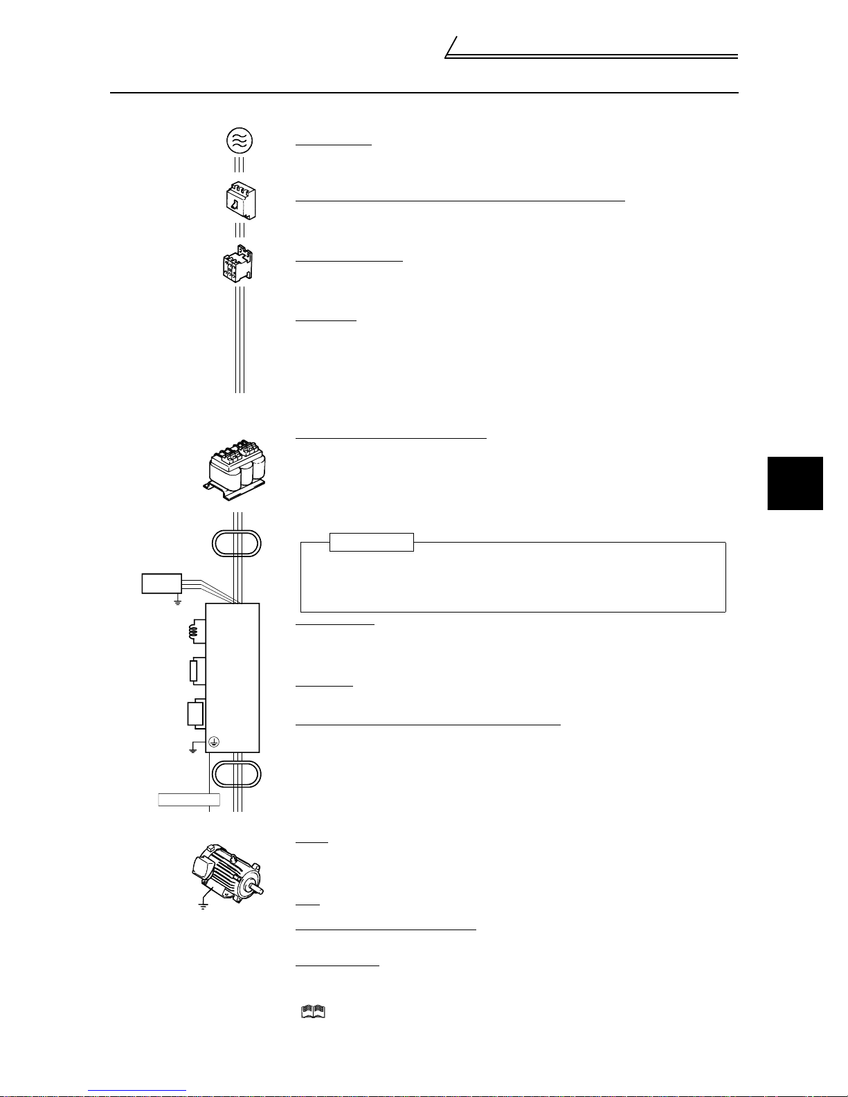
1.1.1 Basic configuration
Power supply
Use within the permissible power supply specifications of the inverter. (Refer to page 99. )
AC reactor
(FR-BAL)
Line noise
filter
Radio noise
filter
Power factor
improvement
reactor
Brake resister
(FR-ABR)
Brake unit
Line noise
filter
PLG cable
(NFB)
or
(ELB)
(MC)
P
P1
P
PR
P
N
Earth(Ground)
RS
Inverter
FR-V500
T
No-fuse breaker (NFB) or earth leakage circuit braker (ELB)
The breaker mus t be selected carefully since a n in-rush current flows in the inverter at
power-on. (Refer to page 3. )
Magnetic contactor
Install the magnetic contactor to ensure safety. (For details, refer to the Instruction Manual
(detailed).)
Do not use this magnetic contactor to start and stop the inverter. Doing so will cause the
inverter life to be shorten.(Refer to page 3.)
Noise filter
Install a noise filter to reduce t he m agnetic noise generated from the inverter.
(Refer to the instruction manual of each option for details.)
• Line noise filter (FR-BSF01) (FR-BLF)
Effective in the range from about 1MHz to 10MHz. When more wires are passed
through, a more e ffective result can be obtained.(Note that the number of wires run
through is limited when fitting to the output side.)
• Radio noise filter (FR-BIF)
Effective in reducing the no ises i n th e AM radi o f reque ncy b and. D edica ted filter f or the
input side.
Power factor improvement reactor
Reactors must be us ed when the power factor is to be improved or whe n the inverter is
installed near a large power sup ply syst em ( 1000k VA or more and wiring dista nce is within
10m). The inverter may be damaged if you do not use reactors.
Make selection carefu lly. (Refer to page 3.)
(Refer to the instruction manual of each option for details.)
• DC reactor (FR-BEL), AC reactor (FR-BAL)
(Caution) Remove the ju m per s across terminals P-P1 to connect to the PC reacto r.
Inverter
The life of the inverter is influenced by ambient temperature. The ambient
temperature should be as low as possible within the permissible range. This must be
noted especially when the inverter is installed in an enclosure. (Refer to page 6.)
Wrong wiring might lead to damage of the inverter. The control signal lines must be
kept fully away from the main circuit to protect them from noise. (Refer to page 7.)
Brake resistor
(Refer to the instruction manual of each option for details)
(Caution) •Remove the jumpers across terminals PR-PX to connect to the inverter.
•Set "1" in Pr. 30 "regenerative function selection".
•Set "10%" in Pr. 70 "special regenerative brake duty".
Brake unit
(Refer to the instruction manual of each option for details)
(Caution) Remove the ju m pers across terminals PR-PX to connect to th e i nverter.
Power regeneration common converter (FR-CV)
• (Refer to the ins truc t io n m anual of each option for details.)
(Caution) •Remove the jumpers across terminals R-R1 and S-S1.
•For a terminal to be connected to the RDYB signal of the FR-CV, set "10" (X10
signal) in any of Pr. 1 80 t o Pr. 183 and Pr. 187(input ter m i nal function selection).
•Set "2" in Pr. 30 "regenerative function selection".
•Select the converter one rank higher in capacity than the inverter.
Selection example: F R-V520-7.5K→FR-CV-11K, FR-V520-15K→FR-CV-18.5K
(When connecting two inverters to one FR-CV, the capacity is 11K + 18.5K =
29.5K. Therefore, select FR-CV-30K.)
Motor
Dedicated motor (Refer to page 99.)
!
This is a highly environmentally-resistant motor based on a totally-enclosed squirrelcage induction motor designed for the vector inverter. Select the motor that matches the
inverter capacity.
PLG
For the PLG dedicated motor, refer to page 12.
Devices connected to the output
Do not install a power factor correction capacitor, surge suppressor or radio noise filter (FRBIF option) in the output side of the inverter.
Earth (Ground)
To prevent an electric shock, always earth (ground) the motor and inverter. For reduction of
induction noise from the pow er line of the inverter, it is recommended to wire the earth
(ground) cable by return ing it to th e ear t h (g ro und) terminal of the inverter.
( For details of noise reducti on t echniques, refer to the Instruction Manual (det ai led) .
1
OUTLINE
2
Basic configuration and connection
of peripheral devices
Caution
• Do not fit capacitive equipment such as power factor correction capacitor, radio noise filter (FR-BIF
option) or surge suppressor to the output side of the inverter. This will cause the inverter to trip or power
factor correction capacitor and surge suppressor to be damaged. If any of the above devices are connected, imme diately remove them. If the FR-BIF radio noise filter is connected, switching power off during
motor operation may result in "E.UVT". In this case, connect the radio noise filter on the primary side of
the magnetic contactor.
• Electromagnetic wave interference
The input/output (main circuit) of t he inverter includes h armonic co mponent s, which may in terfere with
the communication devices (such as AM radios) used near the inverter. In this case, install the FR-BIF
optional radio noise filter (for use in the input side only) or FR-BSF01 or FR-BLF line noise filter to minimize interference.
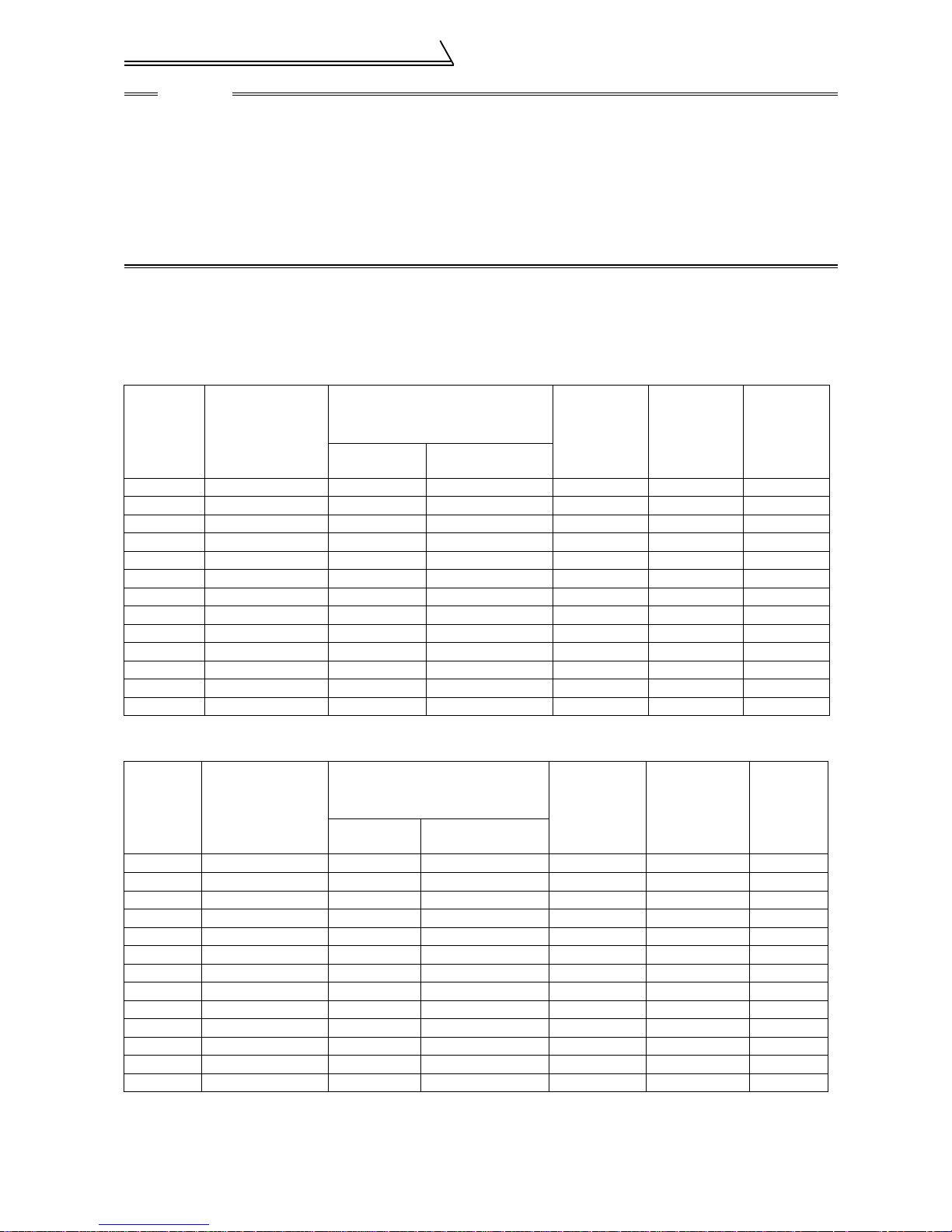
1.1.2 Selection of peripheral devices
Check the capacities of the motor applicable to the inverter you purchased. Refer to the list below and prepare
appropriate peripheral devices.
200V class
No-fuse Breaker
Motor
Output
(kW)
1.5 FR-V520-1.5K 30AF 15A 30AF 15A FR-BAL-1.5K FR-BEL-1.5K S-N10
2.2 FR-V520-2.2K 30AF 20A 30AF 15A FR-BAL-2.2K FR-BEL-2.2K S-N11, N12
3.7 FR-V520-3.7K 30AF 30A 30AF 30A FR-BAL-3.7K FR-BEL-3.7K S-N20
5.5 FR-V520-5.5K 50AF 50A 50AF 40A FR-BAL-5.5K FR-BEL-5.5K S-N25
7.5 FR-V520-7.5K 100AF 60A 50AF 50A FR-BAL-7.5K FR-BEL-7.5K S-N35
11 FR-V520-11K 100AF 75A 100AF 75A FR-BAL-11K FR-BEL-11K S-N50
15 FR-V520-15K 225AF 125A 100A F 100 A FR-BAL-15K FR-BEL-15K S-N65
18.5 FR-V520-18. 5K 225AF 150 A 225AF 125A FR-BAL-22K FR-BEL-18.5K S-N80
22 FR-V520-22K 225AF 175A 225A F 150 A FR-BAL-22K FR-BEL-22K S-N95
30 FR-V520-30K 225AF 225A 225A F 175 A FR-BAL-30K FR-BEL-30K S-N125
37 FR-V520-37K 400AF 250A 225A F 225 A FR-BAL-37K FR-BEL-37K S-N150
45 FR-V520-45K 400AF 300A 400A F 300 A FR-BAL-45K FR-BEL-45K S-N180
55 FR-V520-55K 400AF 400A 400A F 350 A FR-BAL-55K FR-BEL-55K S-N220
Applicable
Inverter
Type
(NFB*1)
or Earth Leakage Cir-
cuit Breaker (ELB
Standard
)
Wi th p o wer fa c tor
improving reactor
Power Factor
Improving AC
Reactor
Power Factor
Improving DC
Reactor
Magnetic
Contactor
(MC)
400V class
No-fuse Breaker
Motor
Output
(kW)
1.5 FR-V540-1.5K 30AF 10A 30AF 10A FR-BAL-H1.5K FR-BEL-H1.5K S-N10
2.2 FR-V540-2.2K 30AF 15A 30AF 10A FR-BAL-H2.2K FR-BEL-H2.2K S-N11, N12
3.7 FR-V540-3.7K 30AF 20A 30AF 15A FR-BAL-H3.7K FR-BEL-H3.7K S-N20
5.5 FR-V540-5.5K 30AF 30A 30AF 20A FR-BAL-H5.5K FR-BEL-H5.5K S-N20
7.5 FR-V540-7.5K 30AF 30A 30AF 30A FR-BAL-H7.5K FR-BEL-H7.5K S-N20
11 FR-V540-11K 50AF 50A 50AF 40A FR-BAL -H11K FR-BEL-H11K S-N20
15 FR-V540-15K 100AF 60A 50AF 50A FR-BAL-H15K FR-BEL-H15K S-N25
18.5 FR-V540-18.5K 100AF 75A 100AF 60A FR-BAL-H22K FR-BEL-H18.5K S-N35
22 FR-V540-22K 100AF 100A 100AF 75A FR-BAL-H22K FR-BEL-H22K S-N50
30 FR-V540-30K 225AF 125A 100AF 100A FR-BAL-H30K FR-BEL-H30K S-N65
37 FR-V540-37K 225AF 150A 225AF 125A FR-BAL-H37K FR-BEL-H37K S-N80
45 FR-V540-45K 225AF 175A 225AF 150A FR-BAL-H45K FR-BEL-H45K S-N80
55 FR-V540-55K 225AF 200A 225AF 175A FR-BAL-H55K FR-BEL-H55K S-N125
Applicable
Inverter
Type
(NFB*1)
or Earth Leakage Cir-
cuit Breaker (ELB
Standard
With p o w e r fac tor
improving reactor
)
Power Factor
Improving AC
Reactor
Power Factor
Improving DC
Reactor
*1. Select the NFB type according to the power supply capacity.
3
Magnetic
Contactor
(MC)
Structure
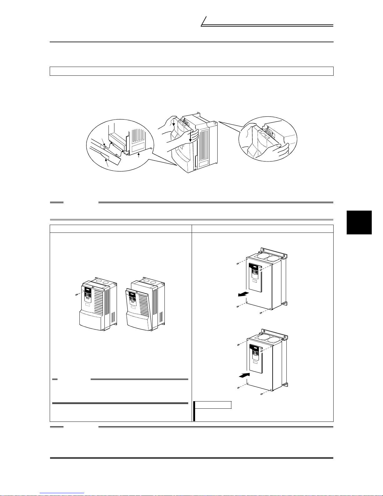
1.2 Structure
1.2.1 Removal and reinstallation of the front cover
FR-V520-1.5K to 7.5K, FR-V540-1.5K to 5.5K
Removal
!
1) Hold both sides of the front cover top and push the front cover down.
2) Hold down the front cover and pull it toward you to remove.
(The front cover may be removed with the PU (FR-DU04
j
Catch
Inverter
Front cove r
! Reinstallation
1) Insert the catches at the bottom of the front cover into the sockets of the inverter.
2) Using the catches as supports, securely press the front cover against the inverter.
CAUTION
When the operation panel is fitted to the removed front cover, reinstall the front cover after removing the
operation panel.
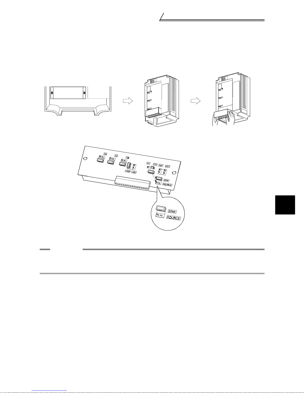
FR-V520-11K, 15K, FR-V540-7.5K to 18.5K FR-V520-18.5K to 55K, FR-V540-22K to 55K
•••• Removal
1) Remove the installation screw at the top of the front cover.
2) Hold both ends of the front cover top.
3) Pull the front cover toward you to remove.
(The front cover may be r em oved with the operation panel
attached.)
/FR-PU04V) on.)
-1
•••• Removal
1) Remove the installation screws at the top of the front cover.
1
OUTLINE
•••• Reinstallation
1) Insert the catches at the front cover bottom into the sockets
of the inverter.
2) Using the catches as supports, securely press the front
cover against the inverter.
3) Fix the front cover with the top screw.
CAUTION
When the operation panel is fitted to the
removed front cover, reinstall the front cover
after removing the operation panel.
CAUTION
1. Fully make sure that the front cover has been reinstalled securely.
2. The same serial number is printed on the capacity plate of the front cover and the rating plate of the
inverter. Before reinstalling the front cover, check the serial numbers to ensure that the cover
removed is reinstalled to the inverter from where it was removed.
•••• Reinstallation
1) Fix the front cover with the installation screws.
REMARKS
The 45K and 55K have two front covers, which are fixed with
eight screws.
4

Structure
1.2.2 Removal and reinstallation of the operation panel
To ensure safety, remove and reinstall the operation panel after powering off.
Removal
!
Hold down the top button of the operation panel and pull the operation panel toward you to remove.
Removal
Reinstallation
When reinstalling the operation panel, insert it straight and reinstall it securely.
! Reinstallation using the connection cable
1) Remove the operation panel.
2) Disconnect the modular jack type relay connector. (Place the disconnected modular jack type relay
connector in the modular jack type relay connector compartment.)
Modular jack type
relay connector
Modular jack type
relay connector compartment
3) Securely plug one end of the connection cable into the PU connector of the inverter and the other end into
the operation panel. (Refer to page 18 for the connection cable.)
CAUTION
Install the operation panel only when the front cover is on the inverter.
5
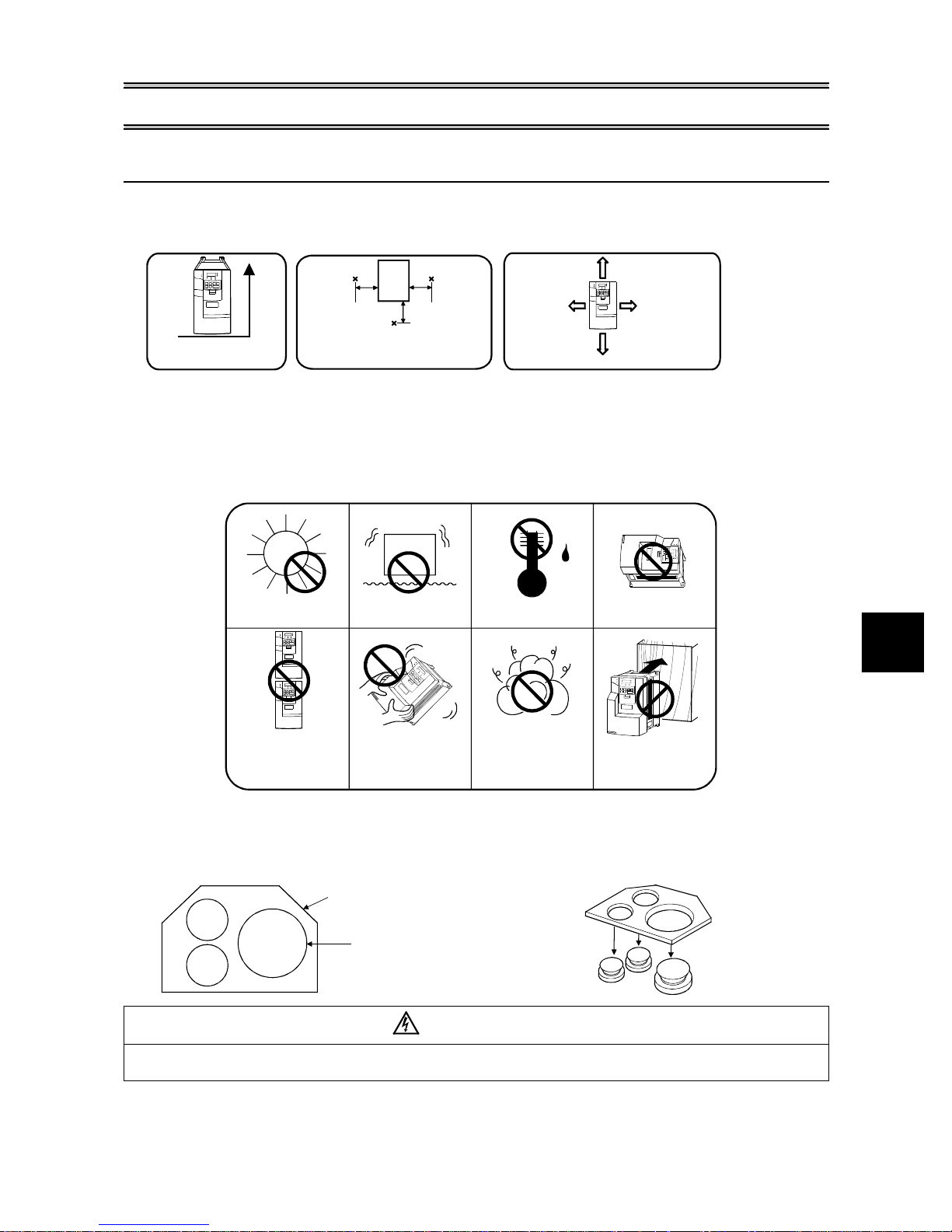
2 INSTALLATION AND WIRING
2.1 Installation of the inverter
Install the inverter under the following conditions.
!
Installation of the inverter
Vertical mounting
Vertical
The inverter consists of precision mechanical and electronic parts. Never install or handle it in any of the following
!
Ambient temperature and humidity
Measurement
position
Inverter
5cm
Measurement
position
Temperature: -10°C to 50°C
Humidity: 90%RH maximum.
Leave enough clearances and take
cooling measures.
5cm
5cm
These clearances are also necessary for
changing the cooling fan.
*1cm or more fo r 2.2K or less.
Enough clearances
5cm or
*
more
10cm
or more
10cm
or more
5cm or
more
*
conditions as doing so could cause an operation fault or failure.
.
Direct sunlight
Vibration
2
(5.9m/s or more)
.
High temperature,
high humidit y
Horizontal placement
.
2
Vertical mounting
When installing two or
more inverters, install
them in parallel .
Wiring cover and handling (15K or less for the 200V class, 18.5K or less for the 400V class)
!
Transportation by
holding front cover.
1) When cable conduits are not connected
Cut the protective bushes of the wiring cover with
nippers or a cutter before running the cables.
Oil mist, flammable gas,
corrosive gas, fluff,
dust etc.
Mounting on
combustible material
2) When cable conduits are connected
Remove the corresponding protective bushes and
connect the cable conduits.
Wiring cover
Protective bush
WARNING
Do not remove the protective bushes when cable conduits are not connected. Otherwise, the cable
sheathes may be scratched by the wiring cover edges, resulting in a short circuit or earth (ground) fault.
INSTALLATION AND WIRING
6
Connection diagram, PLG cable, PU
connector
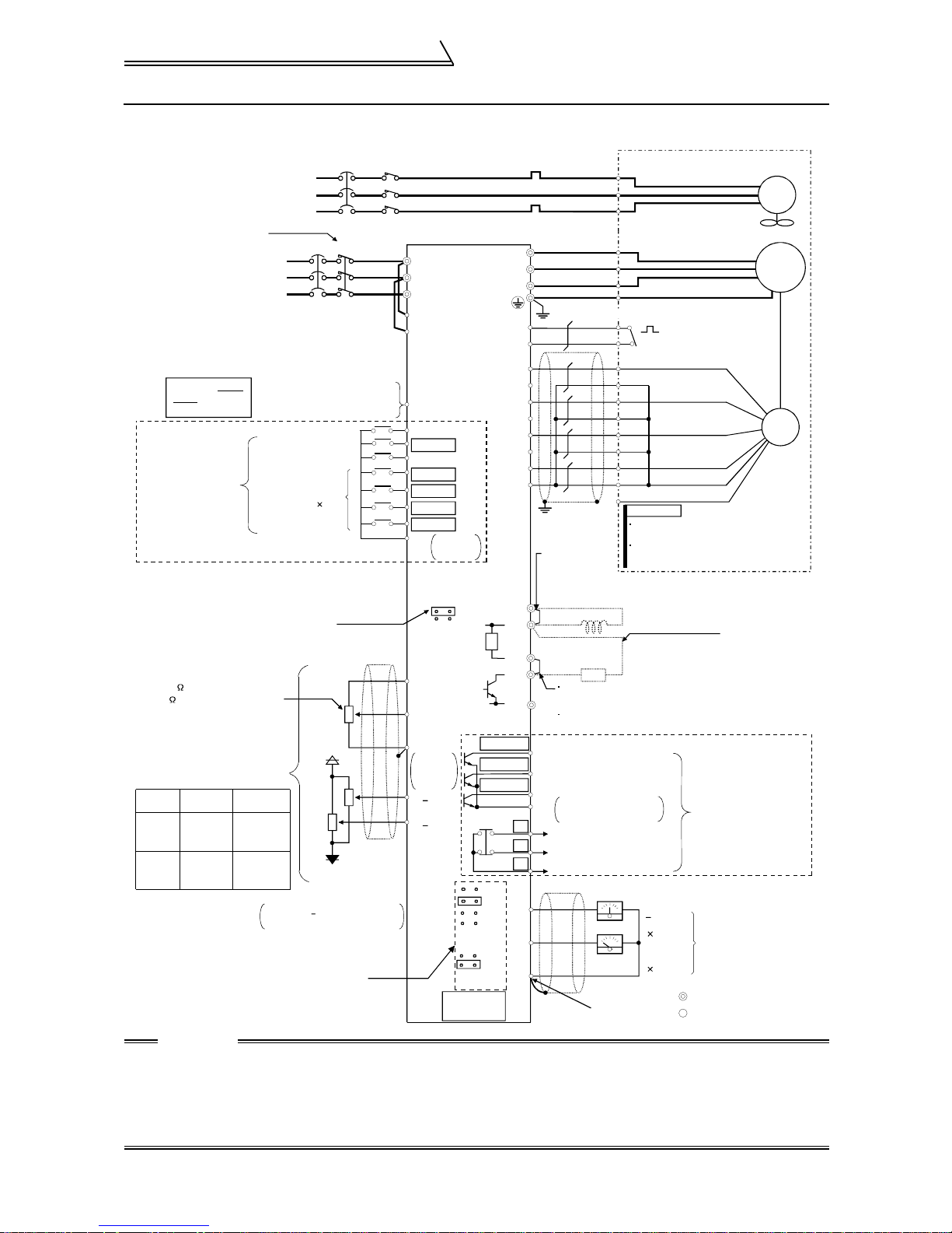
2.2 Connection diagram, PLG cable, PU connector
2.2.1 Connection diagram
NFB MC
Digital input
signal 4
+10V
-10V
External
power supply
+
NFB MC
R
S
T
3
2
1
Vector inverter
(FR-V500)
R
S
T
R1
S1
PC
STF
STR
RES
DI1(RL)
DI2(RM)
DI3(RH)
DI4(RT)
Contact
SD
input
common
SINK
SOURCE
(+10V)
10E
(0 to +10V)
2
5
Analog
input
common
+
1( 10V)
+
3( 10V)
DO1
DO2
DO3
5V
12V
24V
EXT
Differential
Complimentary
PU
connector
R
OCR
U
V
W
Earthing (Grounding)
(class D earthing (grounding))
OH
SD
PA
PAR
PB
PBR
PZ
PZR
PG
SD
Jumper
(When using the
FR-BEL, remove
this jumper.)
P1
P
PX
PR
N
(RUN)
Any of three different
(SU)
signals can be selected
using the parameter.
(IPF)
(Open collector output)
SE
A
B
C
DA1
DA2
5
(Analog output common)
A
B
C
U
V
W
E
G1
G2
A
B
C
D
F
G
S
R
N
R
Jumper (Remove this jumper
when using the FR-ABR.)
Terminal PX is provided for
the 5.5K or less.
Open collector output
common
Alarm output
(Contact output)
Meter
(+)
Verify the power specification
of the motor cooling when
performing wiring.
Refer to page 99
Avoid frequent ON-OFF.
Repeated inrush currents at
power-on will shorten the
converter life.
(Switching life is 100,000)
Take care not to
short terminals
PC-SD.
Terminals DI1 to
DI4 and STR vary
in function with
the input terminal
function selection
(Pr. 180 to Pr. 183,
Pr. 187) settings.
Control input signals (no voltage input allowed)
You can select between sink and source
Refer to page 16 for details.
Speed setting potentiometer
1/2W 1k
2W 1k is recommended for use
when speed setting is changed
frequently.
Terminal
10E, 2, 5
3
3-phase AC
power supply
External transistor common
24VDC power supply
Contact input common (source)
Forward rotation start
Reverse rotation start
Reset
Analog command
input
Speed
Control
Main
speed
command
Torque
restriction
command
Torque
Control
Speed
restriction
command
Torque
command
Prepare a 10V external power
supply for terminals 1, 3.
Change the jumper connector and
Change the jumper connector and
parameter settings according to
parameter settings according to
the PLG specifications.
the PLG specifications.
Refer to page 12 for details.
(Dedicated Motor: SF-V5R)
Match phase sequence.
(Fan should have intake rotation.)
FAN
Match phase sequence.
When using the motor
not equipped with a
thermal protector,
Thermal
set Pr. 9 and Pr. 876
protector
= "0"
PLG
REMARKS
When the motor used is not the vector
inverter motor, the pin numbers are different.
The N pin of the PLG designed for vector
inverter motor is case-earthed.
FR-BEL power factor
improving DC reactor
(option)
FR-ABR high-duty
brake resistor
(option)
+
10V
12 bits
(-)
1ch
0 to 10V
12 bits
1ch
Across terminals P
and PR, connect only
the optional,
recommended brake
resistor. In addition,
never short these
terminals.
Terminal PR is
provided for the 15K
or less.
Terminals DO1 to DO3
and ABC vary in function
with the output terminal
function selection
(Pr. 190 to Pr. 192,
Pr. 195) settings.
load impedance of 10kW or more
Monitor output
Main circuit terminal
Control circuit terminal
IM
CAUTION
• To prevent a malfunction caused by noise, separate the signal cables more than 10cm from the power
cables.
• During wiring, do not leave wire off-cuts in the inverter.
Wire off-cuts will cause an alarm, failure or malfunction. Always keep the inverter clean. When drilling
mounting holes in a control box etc., take care not to allow chips and other foreign matter to enter the
inverter.
7
Connection diagram, PLG cable, PU
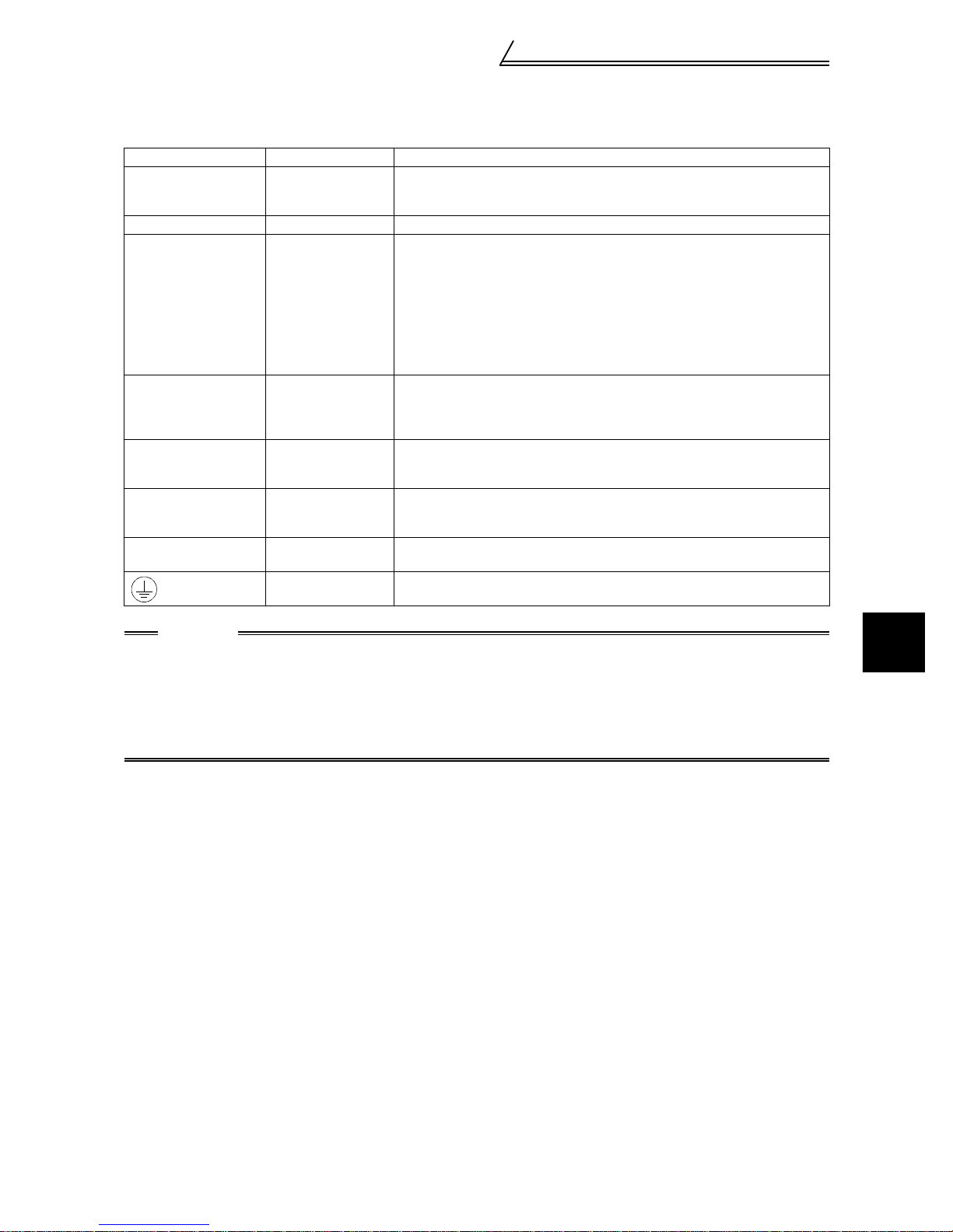
2.2.2 Main circuit
(1) Specification of main circuit terminal
Terminal Symbol Terminal Name Description
R, S, T AC power input
U, V, W Inverter output Connect a motor.
R1, S1
P, PR
P, N
P, P1
PR, PX
Power supply for
control circuit
Brake resistor
connection
Brake unit
connection
Power factor
improving DC
reactor connection
Built-in brake circuit
connection
Earth (Ground) For earthing (grounding) the inver t er chassis. Must be earthed (grounded).
Connect to the commercial power supply.
Keep these terminals open when using the high power factor converter (FRHC) or power regenerati on common converter (FR-CV).
Connected to the AC power supply terminals R and S. To retain the alarm
display and alarm output or when using the high power factor converter (FR HC) or power regeneration common converter (FR-CV), remove the jumpers
from terminals R-R1 and S-S1 and apply external power to these terminals.
Do not turn off the power supply for control circuit (R1, S1) with the main
circuit power (R, S, T) on. Doing so may damage the inverter. The circuit
should be configured so that the main circuit power (R, S, T) is also turned off
when the power supply for control circuit (R1, S1) is off.
15K or less : 60VA, 18.5K to 55K : 80VA
Disconnect the jumper from term inals PR-PX (5.5K or less) and connect the
optional brake resistor (FR- ABR) across terminals P-PR.
For the 15K or less, connect ing t he r esistor further provides regenerative
braking power.
Connect the optional FR-BU brake unit, BU type brake unit, power
regeneration commo n converter (FR-CV) or high power factor con ver ter (FRHC).
Disconnect the jumper from te rmi nals P-P1 and connect the optional power
factor improving reactor (F R -BEL).
When the jumper is connected across terminals PX-PR (factory setting), the
built-in brake circuit is valid. (Provided for the 5.5K or less.)
connector
CAUTION
• The inverter will be damaged if power is applied to the inverter output terminals (U, V, W). Never perform such wiring.
• When connecting the dedicated brake resistor (FR-ABR), remove jumpers across terminals PR-PX
(5.5K or less). Set "1" in Pr. 30 "regenerative function selection". Refer to the Instruction Manual
(detailed) for details.
• When connecting the brake unit (FR-BU, BU), remove jumpers across terminals PR-PX (5.5K or less).
Refer to the Instruction Manual (detailed) for details.
2
INSTALLATION AND WIRING
8
Connection diagram, PLG cable, PU
connector
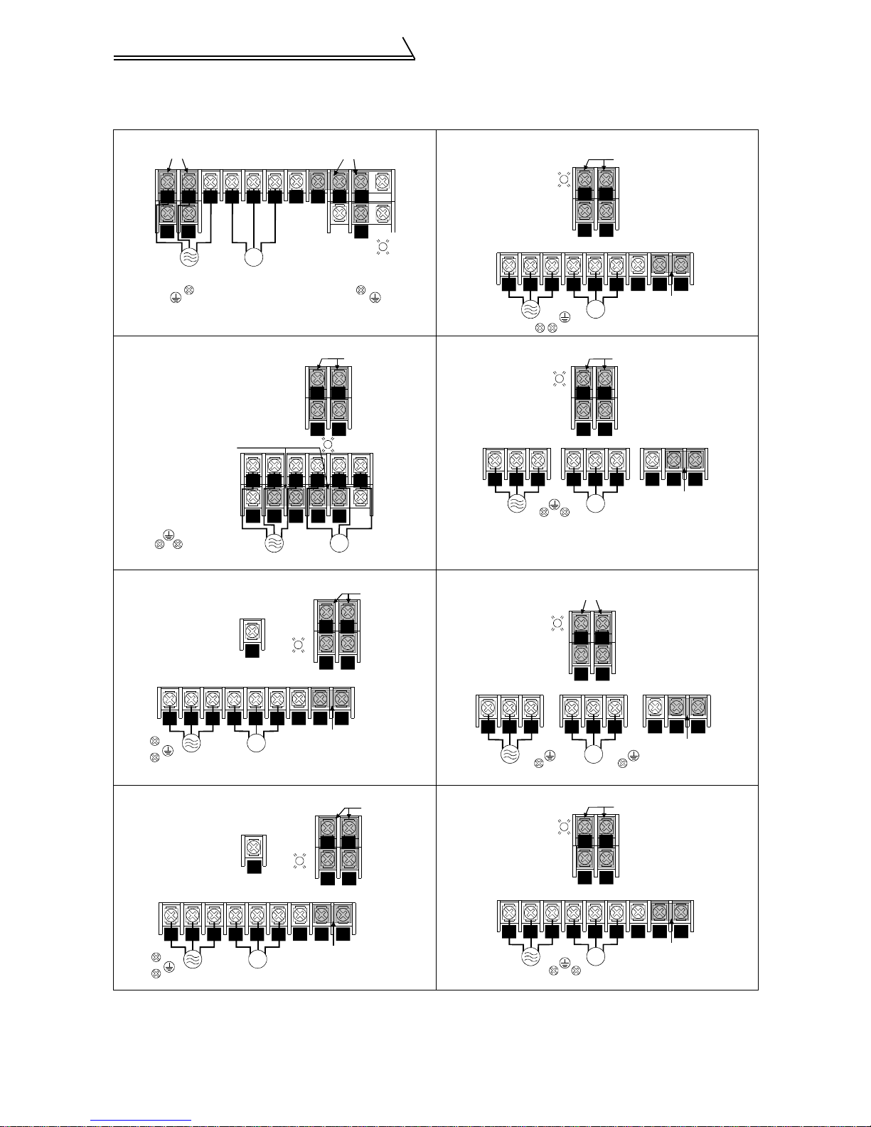
(2) Terminal arrangement of the main circuit terminal
In the main circuit of the inverter, the terminals are arranged as shown below:
200V class
FR-V520-1.5K, 2.2K FR-V520-18.5K
Jumpers
RTS
Screw size (M4)
UVW
Jumpers
Charge lamp
PR
P1
P
N
R1 S1
Jumpers
Screw size (M4)
S1R1
Power supply
Screw size (M4)
FR-V520-3.7K, 5.5K, 7.5K
Screw size (M4)
Jumper
Screw size (M5)
Screw size (M5)
IM
Motor
ST
R
N
P1 PR PX
R1 S1
P
PX
Charge lamp
Jumpers
RS
Charge lamp
UVW
IM
FR-V520-22K
Charge lamp
R
S
7.5K is not provided with the PX terminal and PX- PR jum per.
FR-V520-11K FR-V520-30K, 37K
Screw size (M5)
Screw size (M6)
Screw size (M4)
PR
Charge
lamp
R1 S1
Jumpers
Charge lam p
RS
RNRS
Screw size (M8)
ST P
T
U V W
IM
Screw size (M6)
R1 S1
R
S
V
IM
Screw size (M6)
Jumpers
R1 S1
RS
P1
Jumper
Jumpers
Screw size (M4)
Screw size (M8)
W
N
Screw size (M4)
Screw size (M10)
P1U
Jumper
P
RS
Screw size (M6)
T
U V W
IM
FR-V520-15K FR-V520-45K, 55K
Screw size (M4)
Screw size (M5)
PR
Charge
Screw size (M8)
RS
T
Screw size (M6)
U V W
lamp
IM
N
N
P1
Jumper
R1 S1
RS
P1
Jumper
P
P
Jumpers
R
ST
Screw size (M8)
Charge lamp
ST P
V W
U
IM
R1 S1
RNRS
U V W
IM
Screw size (M8)
N
Jumpers
Screw size (M4)
Screw size (M12)
P
Jumper
P1
Jumper
P1
9
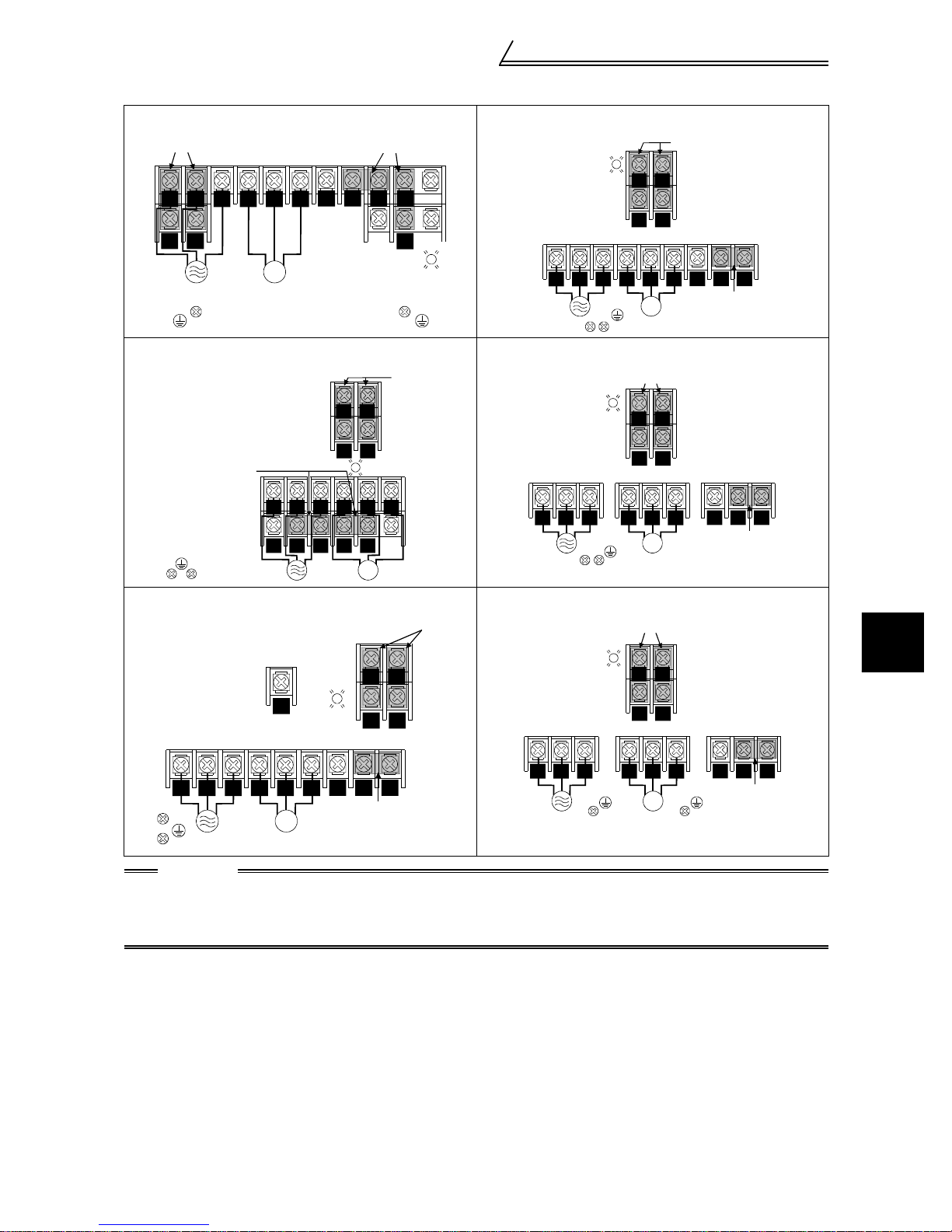
Connection diagram, PLG cable, PU
400V class
FR-V540-1.5K, 2.2K FR-V540-18.5K
connector
Jumpers
RS
Power supply Motor
Screw size (M4)
T
S1R1
Screw size (M4)
UVW
N
IM
Jumpers
P1
P
Charge lamp
PR
PX
Charge lamp
R1 S1
ST P
U V W
FR-V540-3.7K, 5.5K FR-V540-22K
Jumper
Screw size (M4)
Screw size (M4)
Screw size (M4)
RST
NP
P1 PR PX
R1 S1
S
R
Charge lamp
UVW
IM
Jumpers
Charge lamp
RST N P
Jumpers
R1 S1
U V W
Screw size (M6)
FR-V540-7.5K, 11K, 15K FR-V540-30K, 37K, 45K, 55K
Screw size (M5)
Screw size (M6)
Screw size (M4)
PR
Charge
lamp
Jumpers
Charge lamp
R1 S1
RS
Jumpers
R1 S1
Jumpers
Screw size (M4)
RNRS
Screw size (M6)
IM
Screw size (M6)
Screw size (M4)
RS
Screw size (M6)
IM
Screw size (M4)
RS
P1
Jumper
P1
Jumper
2
Screw size (M8)
RST
IM
Screw size (M6)
CAUTION
• Always connect the power supply cables to R, S, T. If they are connected to U, V, W , the inverter will be
damaged. (Phase sequence needs not to be matched.)
• Connect the motor to U, V, W. At this time, turning on the fo rward rotation switch (sig nal) rotates the
motor in the counterclockwise direction when viewed from the motor shaft.
RST
P1U V W
N
P
Jumper
U V W
IM
Screw size (M8)
P1
NP
Jumper
INSTALLATION AND WIRING
10
Connection diagram, PLG cable, PU
connector
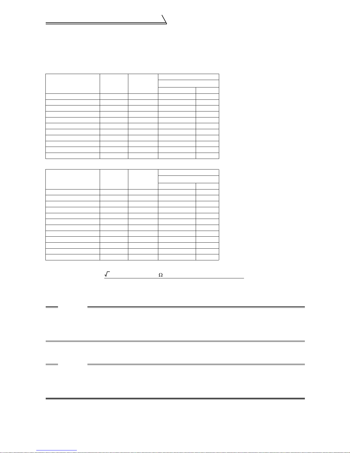
(3) Cables and wiring length
Select the recommended cable size to ensure that a voltage drop will be 2% max.
If the wiring distance between the inverter and motor is long, the motor torque will decrease due to the voltage drop of the
main circuit cable especially at high-frequency output. The PLG signal will also be affected by the voltage drop.
The following table indicates a selection example for the wiring length of 20m.
200V class (When input power supply is 220V)
Applicable Inverter
Type
FR-V520-1.5K, 2.2K M4 1.5 2 2
FR-V520-3.7K M5 2.5 3.5 3.5
FR-V520-5.5K M5 2.5 5.5 5.5
FR-V520-7.5K M5 2.5 14 8
FR-V520-11K M6 4.4 14 14
FR-V520-15K M8 7.8 22 22
FR-V520-18.5K, 22K M8 7.8 38 38
FR-V520-30K M10 14.7 60 60
FR-V520-37K M10 14.7 100 100
FR-V520-45K M12 24.5 100 100
FR-V520-55K M12 24.5 150 150
Terminal
Screw Size
Tightening
Torque
N·m
400V class (When input power supply is 440V)
Applicable Inverter
Type
FR-V540-1.5K, 2.2K M4 1.5 2 2
FR-V540-3.7K M4 1.5 2 2
FR-V540-5.5K M4 1.5 3.5 2
FR-V540-7.5K M6 4.4 3.5 3.5
FR-V540-11K M6 4.4 5.5 5.5
FR-V540-15K M6 4.4 14 8
FR-V540-18.5K M6 4.4 14 8
FR-V540-22K M6 4.4 22 14
FR-V540-30K M8 7.8 22 22
FR-V540-37K M8 7.8 38 22
FR-V540-45K M8 7.8 38 38
FR-V540-55K M8 7.8 60 60
Terminal
Screw Size
The line voltage drop can be calculated by the following expression:
Tightening
Torque
N·m
HIV Cables
mm
R, S, T
HIV Cables
mm
R, S, T
2
U, V, W
2
U, V, W
Line voltage drop [V]
3 × cable resistance[m /m]× wiring distance[m] × current[A]
=
1000
Use a larger diameter cable when the wiring distance is long or when it is desired to decrease the voltage drop
(torque reduction) in the low speed range.
CAUTION
• Tighten the terminal screw to the specified torque.
A screw that has been tighten too loosely can cause a short circuit or malfunction.
A screw that has been tighten too tightl y can cau se a shor t circuit or malfun ction due to the unit br eakage .
• The crimping terminals recommended for use to wire the po wer supply and mo tor are those pr ovided
with insulation sleeves.
(4) Wiring length
The wiring length should be 100m maximum. (during vector control)
!
CAUTION
• Especially for long-distance wiring, the inverter may be affected by a charging current caused by the
stray capacitances of the wiring, leading to a malfunction of the overcurrent protective function or a
malfunction or fault of the equipment connected on the secondary side. If fast-responce current
restriction malfunctions when fast-responce current restrict ion function is made valid, disable fastresponce current restriction. (Refer to Pr.156 "stall prevention operation selection". )
(5) Cable gause for the control circuit power
• Cable gause: 0.75mm2 to 2mm
• Tightening torque: 1.5N•m
2
11
Connection diagram, PLG cable, PU
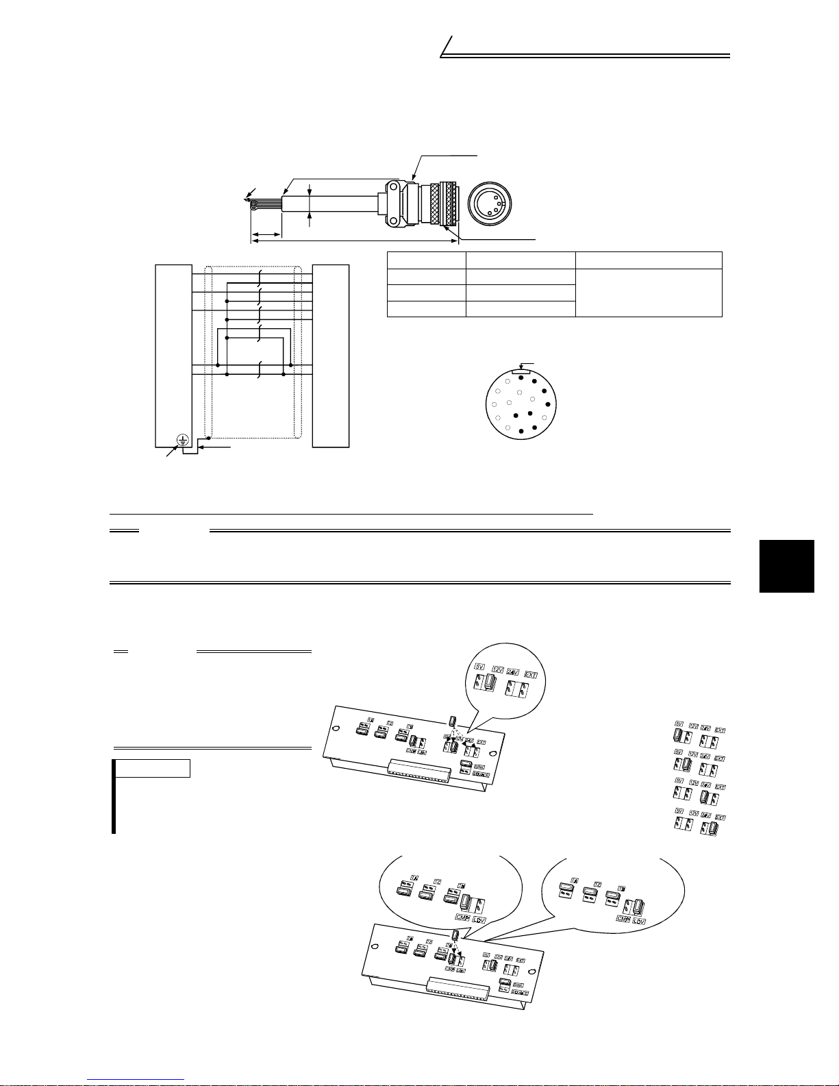
2.2.3 PLG connection cable (FR-V5CBL)
When using a dedicated motor (SF-V5R series), use a PLG cable (FR-V5CBL) for connection.
connector
Inverter side
60
2
F-DPEVSB 12P
11
A
B
C
D
F
G
S
R
Earth (Ground) wire
FR-V500 PLG (SF-V5R)
PA
PAR
PB
PBR
PZ
PZR
PG
SD
2mm
Inverter earth ( ground) terminal
PLG side
×
L
connector
0.2mm
MS3057-12A
2
MS3106B20-29S
Type Length L (m) Remarks
FR-V5CBL5 5
FR-V5CBL30 30
Contact us separately for other lengths.
A
M
N
L
T
K
S
J
H
MS3106B20-29S
(As viewed from wiring side)
Standard productFR-V5CBL15 15
Positioning keyway
B
C
D
P
E
R
F
G
(Unit: mm )
2.2.4 Setting the PLG
When a dedicated PLG cable (FR-V5CBL) is used, a setting change may not be required.
CAUTION
Make setting correctly.
Fitting the jumper connector to the position exceedin g the power specification results in a PLG failure.
Fitting the jumper connector to the position be low the power specification results in a PLG malfunction.
(1) Setting the power supply specification of the PLG and pulse output type
Switch the position of the jumper connector on the back surface of the control c ircuit terminal block according
to the PLG specification. (Refer to page 16 for removal and installation of the control circuit terminal block.)
2
CAUTION
• PLG power supply jumper
connector
The connector is fitted to 12V
at factory shipment. Switch its
position according to power
supply specification.
REMARKS
Since the specification of the PL G of
the conventional motors (SF-VR, SFJR with PLG) is 5V, fit the jumper connector to 5V.
PLG output circuit jumper
!
connector
The connector is fitted to
complimentary at factory shipment.
Switch its position according to
output circuit.
Complimentary (CMP)
Terminating resistance
12
Power supply voltage is 5.5V
Power supply voltage is 12V
Power supply voltage is 24V
INSTALLATION AND WIRING
Power supply voltage is external
Differential line driver (LDV)
Terminating resistance
Connection diagram, PLG cable, PU
connector
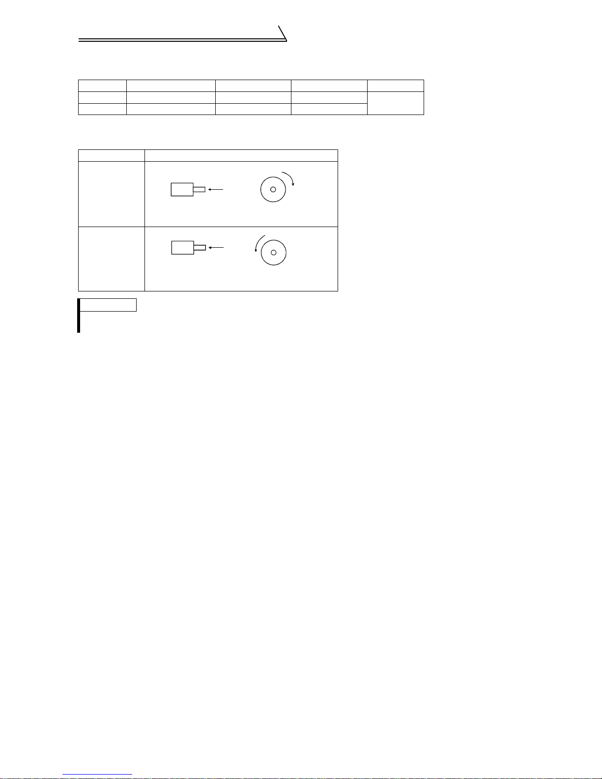
(2) Setting the number of PLG pulses and PLG rotation direction
Set the following parameters according to the PLG specification.
Parameter Name Factory Setting Setting Range Remarks
851 Number of PLG pulses 2048 0 to 4096
852 PLG rotation direction 1 0, 1
The rotation direction monitor of the parameter unit displays the rotation direction of the encoder,
!
refer to the following table.
Pr. 852 Setting Relationship between the motor and PLG
Extension
mode
CW
0
1
(factory setting)
A
PLG
Forward rotation is clockwise rotation
when viewed from A.
CCW
A
PLGAPLG
Forward rotation is counterclockwise rotation
when viewed from A.
REMARKS
• By setting "1" in Pr.160 "extended function selection", Pr. 851 and Pr. 852 are made valid.
• The number of P LG pulses should be between 1000 and 4096.
When using a conventional motor and a PLG cable (FR-VCBL/FR-JCBL), refer to the
!
Instruction Manual (detailed).
13
2.2.5 Control circuit
(1) Specifications of control circuit ter mi nals
Terminal
Type
Symbol
STF Forward rotation start
STR Reverse rotation start
DI1 to DI4
OH T hermal protector input
RES Reset
Contact input
SD
PC
10E
2 Speed setting (voltage)
3 Torqu e setting terminal
Input signals
Speed setting
1
5 Speed setting common
PA
PAR
PB
PBR
PZ
PZR
PLG signal
PG
SD
Terminal Name Description
Turn on the STF signal to start forward
rotation and turn it off to stop.
Turn on the STR signal to start reverse
rotation and turn it off to stop.
The terminal function varies with the input
terminal function selection (Pr. 187) setting.
Refer to page 61 for details.
Digital input
terminals 1 to 4
Contact input common
(sink)
24VDC power supply
and external transistor
common, contact inpu t
common (source)
Speed setting power
supply
Multi-function setting
terminal
A-phase signal input
terminal
A-phase inverted signal
input terminal
B-phase signal input
terminal
B-phase inverted signal
input terminal
Z-phase signal input
terminal
Z-phase inverted signal
input terminal
PLG power supply
terminal
(Positive side)
Power supply earth
(ground) terminal
The terminal functions vary wi th the in put terminal function selection (Pr. 180 to Pr.
183) settings. Refer to page 61 for details.
Temperature sensor terminal input for motor overheat protection.
OHT error occurs when terminals OH and SD are open.
Used to reset instantly. By setting Pr. 75 "reset selection", reset input possible or
reset input possible only during protective circuit operation can be selected. Turn on
the RES signal for more than 0. 1s, then turn it off.
Common to the contact input. Common output terminal for 24VDC 0.1A power
supply (PC terminal). Isol at ed fr om te rmi nals 5 and SE.
When connecting a transistor output (open collector output), such as a
programmable contr ol ler, connect the ex te rn al p ower supply common for transistor
output to this terminal to pr event a malfunction caused by a sneak current .
PC-SD can be used as a 24VDC, 0.1A power supply. Note that this connection does
not prevent a sneak curr ent.
When source logic has be en selected, this terminal serves as a contact input
common.
10VDC, permissible lo ad current 10mA
By entering 0 to 10VDC, the m axi m um output speed is reached at 10V and I/O are
proportional. Acts as a spe ed command terminal for speed control or as a speed
restriction for torque control. Input resistance 10kΩ, maximum permissible vol t age
20V.
Acts as a torque setting signal fo r tor que control or a torque restriction signal for
speed control and posi tion control.
Acts as an input terminal when torque bias function by external analog is selected.
0 to ±10VDC input, input resistance 10kΩ, maximum permissibl e voltage ±20VDC
Since this is a multi-function sel ec tion terminal, its function varies with the Pr. 868
"No. 1 terminal function assignment" setting. The function of this terminal is factoryset to adding auxiliary of speed setting terminal of terminal 2.
Refer to Pr. 868 "No. 1 terminal function assignm ent " i n th e Inst r uct i on M anual
(detailed).
0 to ±10VDC input, input resistance 10kΩ, maximum permissibl e voltage ±20V
Speed setting signal (term in al 2, 1 or 3) co mmon terminal.
Isolated from terminals SD and SE. D o no t e arth(ground).
A-, B- and Z-phase signals are inp ut from th e PLG.
The PLG jumper connec tor is set to complimentary when shipped from the f ac to ry.
Thus, the PLG need not be conn ected to PAR, PB R, and PZR.
Power supply f or PLG. You can switch the power supply between 5, 12 and 24VDC.
You can also switch to external power supply.
The PLG jumper connecto r is set to 12VDC when shipped from the factory. (Refer
to page 12.)
Common terminal for the PLG power supply.
Isolated from terminals 5 and SE.
Do not earth (ground).
Connection diagram, PLG cable, PU
connector
When the STF and STR signals are
turned on simultaneously, the stop
command is given.
2
INSTALLATION AND WIRING
14
Connection diagram, PLG cable, PU
connector
Terminal
Type
Symbol
A, B, C Al arm out put
Contact
DO1 to
DO3
SE
Open collector
Output signals
DA1 A n al og signal output
DA2 A n al og signal output
Analog
5
– PU connector
RS-485
Communication
Terminal Name Description
1 contact output indicating that the output has been stopped by the invert er
protective function
230V A C 0.3 A, 30V DC 0. 3A. Al ar m: di scon ti nuity acro ss B -C (c onti nui ty ac ros s A-C ),
Normal: continuity across B-C (discontinuity across A-C).
The terminal function varies with the output terminal function selection (Pr. 195 )
setting.
Refer to page 61 for details.
Digital output terminals
1 to 3
Open collector output
common
Analog signal output
common
Permissible load 24VDC 0.1A
The terminal functions vary with the output terminal function selection (Pr. 190 to Pr.
192) settings. Refer to page 61 for details.
Common terminal for terminals DO1, DO2 and DO3. Isolated from terminals SD and
5.
One selected from the monitoring items,
such as the speed, is outp ut .
The output signal is proportional to the
magnitude of the corresponding monitoring
item.
Common terminal for DA1 and DA2.
Isolated from terminals SD and SE.
Do not earth(ground).
With the PU connector, communication can be m ade through RS -485.
• Conforming standard : EIA Standard RS-485
• Transmission format : Multidrop link system
• Communication speed: Maximum 19200bps
• Overall length : 500m
Factory setting of output item :
*
Speed monitoring, output si gnal 0 to
±10VDC, permissible load current 1mA
Factory setting of output item :
Torq ue monitoring, output signal 0 to
10VDC, permissible load current 1mA
* Not output during inverter reset.
REMARKS
For the input terminal function switchover timing, refer to page 42.
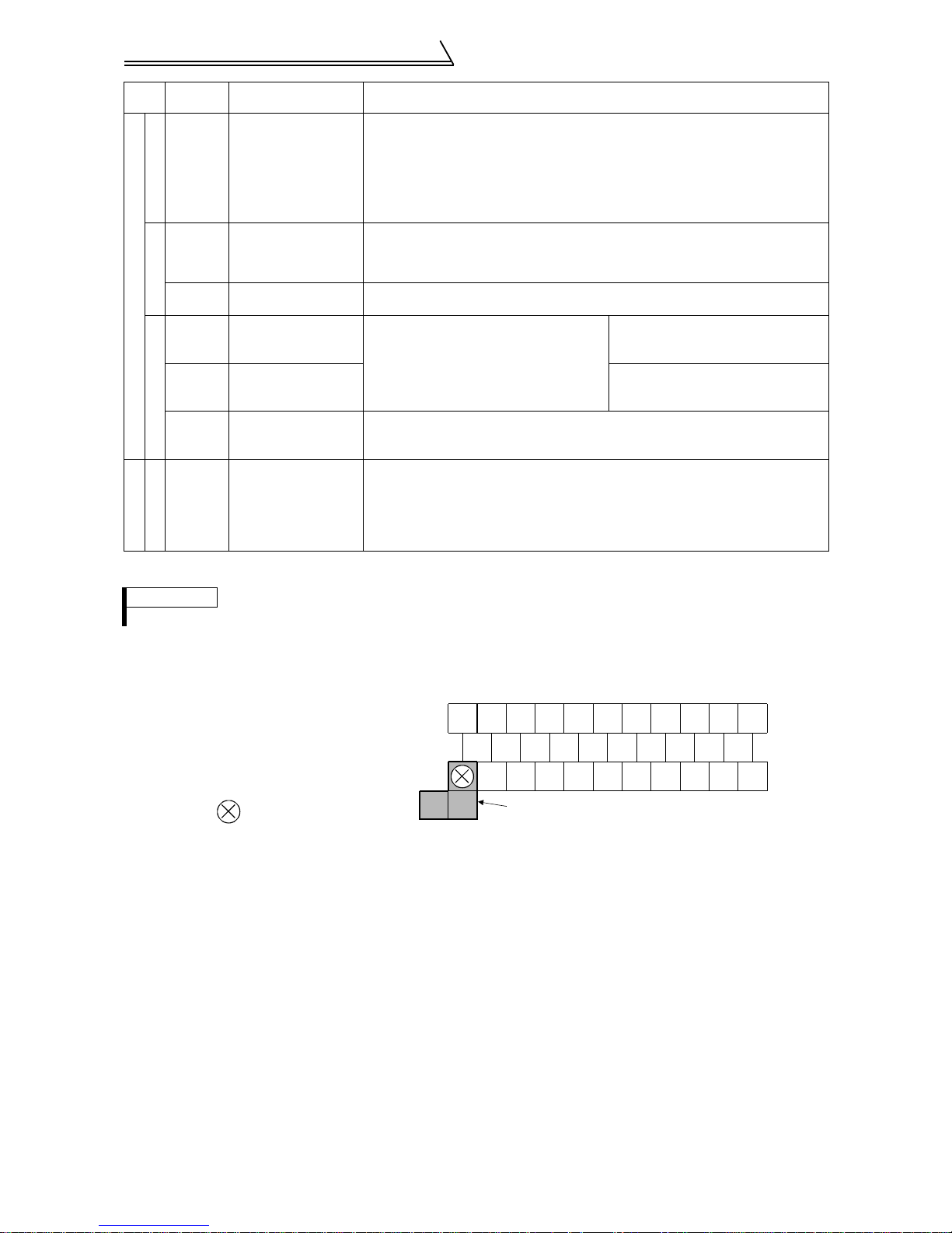
(2) Control circuit terminal layout
Terminal screw size: M3.5
Tightening torque : 1.2N·m
When connecting three or more control cables
to the No. 5 terminal, con nect the accessory
No. 5 terminal dedicated L- shaped jumper to
the No. 5 terminal.
In this case no cable should be connected to
the screw in the part.
A
BDO1DO2DI4
C
10E
2 DA1 SE PZ PZR PG RES
3 1 PA PAR PB PBR SD OH
5
5
DO3
DA2
Jumper
DI3 DI2 DI1
STR
STF
PC
SD
(3) Wiring instructions
1) Terminals 5, SD and SE are common to the I/O signals and isolated from each other. These common terminals
must not be connected to each other nor earthed (grounded).
2) Use shielded or twisted cables for connection to the control circuit terminals and run them away from the main
and power circuits (including the 200V relay sequence circuit).
3) Since the control circuit input signals are micro currents, use two parallel micro signal contacts or a twin contact to prevent a contact fault.
4) It is recommended to use the cables of 0.75mm
cable gauge used is 1.25mm
2
or more, the front cover may be lifted when there are many cables running or the
cables are run improperly, resulting in an operation panel or parameter unit contact fault.
5) The maximum wiring length should be 30m.
2
gauge for connection to the control circuit terminals. If the
15
Connection diagram, PLG cable, PU
connector
(4) Changing the control logic
The input signals are factory set to sink logic (SINK).
To change the control logic, the jumper connector on the back of the control circuit terminal block must be moved to
the other position.
(The output signals may be used in either the sink or source logic independently of the jumper connector position.)
1) Loosen the two mounting screws in both ends of the control circuit terminal block. (The screws cannot be
removed.) With both hands, pull down the terminal block from the back of the control circuit terminals.
2) Remove the jumper connector from the sink logic (SINK) position on the back surface of the control circuit terminal block and fit it to the source logic (SOURCE) position.
3) Using care not to bend the pins of the inverter's control circuit connector, reinstall the control circuit terminal
block and fix it with the mounting screws.
CAUTION
1. Make sure that the control circuit connector is fitted correctly.
2. While power is on, never disconnect the control circuit terminal block.
3. The sink-source logic change-over jumper connector must be fitted in o nly on e of those p ositio ns. If
it is fitted in both positions at the same time, the inverte r may be damaged.
2
INSTALLATION AND WIRING
16
Connection diagram, PLG cable, PU
connector
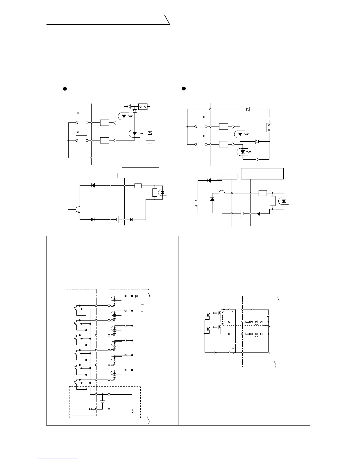
4) Sink logic type and source logic type
• The sink logic type is a logic where a signal turns on when a current flows out of the corresponding signal
input terminal.
Terminal SD is common to the contact input signals. Termi nal SE is common to the open collector output signals.
• The source logic type is a logic where a signal turns on when a current flows into the corresponding signal
input terminal.Terminal PC is common to the contact input signals. Terminal SE is common to the open collector output signals.
Current flow concerning the RUN signal
when sink logic is selected
Sink logic
Current
STF
R
STR
R
SD
Inverter
RUN
SE
When using an external power supply for transistor output
!
24VDC
Sink connector
DC input (sink type)
<Example : AX40>
1
R
9
R
• Sink logic type
Using terminal PC as a common terminal prevents a
malfunction caused by undesirable current. (Do not
connect terminal SD of the inverter with terminal 0V
of the external power supply. When using terminals
PC-SD as a 24VDC power supply, do not install a
power supply in parallel in the outside of the inverter.
Doing so may cause a malfunction due to undesirable current.)
STF
STR
RH
RM
RL
RES
PC
SD
Inverter
24VDC
(SD)
AY40 type
transistor
output module
1
2
3
4
5
6
9
10
24VDC
Current flow concerning the RUN signal
when source logic is selected
Source logic
PC
Current
STF
STR
R
R
Inverter
RUN
SE
DC input (source type)
<Example : AX80>
1
9
24VDC
Source
connector
R
R
• Source logic type
Use terminal SD as a common to prevent a malfunction caused by undesirable current.
AY80 type
transistor
output module
9
1
2
10
PC
STF
STR
24VDC
SD
Inverter
24VDC
(SD)
17
Connection diagram, PLG cable, PU
connector
2.2.6 Connection to the PU connector
(1) When connecting the operation panel or parameter unit using a connection cable
<Recommended connection cable>
• Parameter unit connection cable (FR-CB2) (option) or the following connector and cable available on the market
• Connector : RJ45 connector
Example: 5-554720-3 of Tyco Electronics Corporation
• Cable : Cable conforming to EIA568 (e.g. 10BASE-T cable)
Example:
• Maximum wiring length : 20m
SG LPE V 0.5mm x 4P (twisted pair cable, 4 pairs) of M itsubishi Cable Industries, LTD.
(2) For computer link communication
Using the PU connector, you can perform communication operation from a personal computer etc. By connecting
the PU connector to computers such as a personal computer and FA unit with a communication cable, you can run/
monitor the inverter and read/write parameter values using a user program.
Refer to the Instruction Manual (detailed) for details.
• Conforming Standard : EIA Standard RS-485
• Transmission form : Multidrop link system
• Communication speed : Maximum 19200bps
• Overall length : 500m
CAUTION
Do not connect the PU connector to the computer's LAN b oard, FAX modem socket or telephone connector. Doing so may damage the inverter due to electrical specification differences.
2.2.7 Notes on earthing (grounding)
Leakage currents flow in the inverter. To prevent an electric shock, the inverter and motor must be earthed
!
(grounded).
Use the dedicated earth (ground) terminal to earth (ground) the inverter. (Do not use the screw in the case, chassis,
etc.)
Use the largest possible gauge for the earth (ground) cable. The gauge should be equal to or larger than those
!
indicated in the following table. The earthing (grounding) point should be as near as possible to the inverter to
minimize the earth (ground) cable length.
Motor Capacity
2.2kW or less 2 2
3.7kW 3.5 2
5.5kW, 7.5kW 5.5 3.5
11kW, 1 5kW 14 8
18.5kW to 37kW 22 14
45kW, 55kW 38 22
Earth (Ground) the motor on the inverter side using one wire of the 4-core cable.
!
Earth (Ground) Cable Gauge
200V class 400V class
2
INSTALLATION AND WIRING
18

Setting the motor
2.3 Setting the m otor
This inverter is factory-set to run the dedicated motor (SF-V5R (1500r/min series) with PLG)
(It is not necessary to reset the inverter if you use the dedicated motor (SF-V5R (1500r/min series) with PLG) (only
when inverter capacity = motor capacity).)
POINT
The parameter below is extended mode parameter. Set "1" in Pr. 160 "extended function selection".
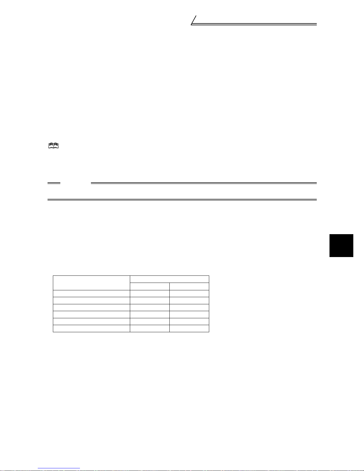
2.3.1 Dedicated motor (SF-V5R (1500r/min series))
1Check that the Pr.71 "applied motor" (extended mode) setting is "30" (SF-V5R) (factory setting value).
2.3.2 Motor one rank lower than the dedicated motor (SF-V5R (1500r/min series))
(1) Set the parameter shown below.
Parameter Name Factory Setting Setting Range
80 Motor capacity Inverter ca pacity 0.4kW to 55kW
19
Setting the motor
REMARKS
When using a conventional motor (SF-VR, SF-JR) or other motors, refer to the
Instruction Manual (detailed).
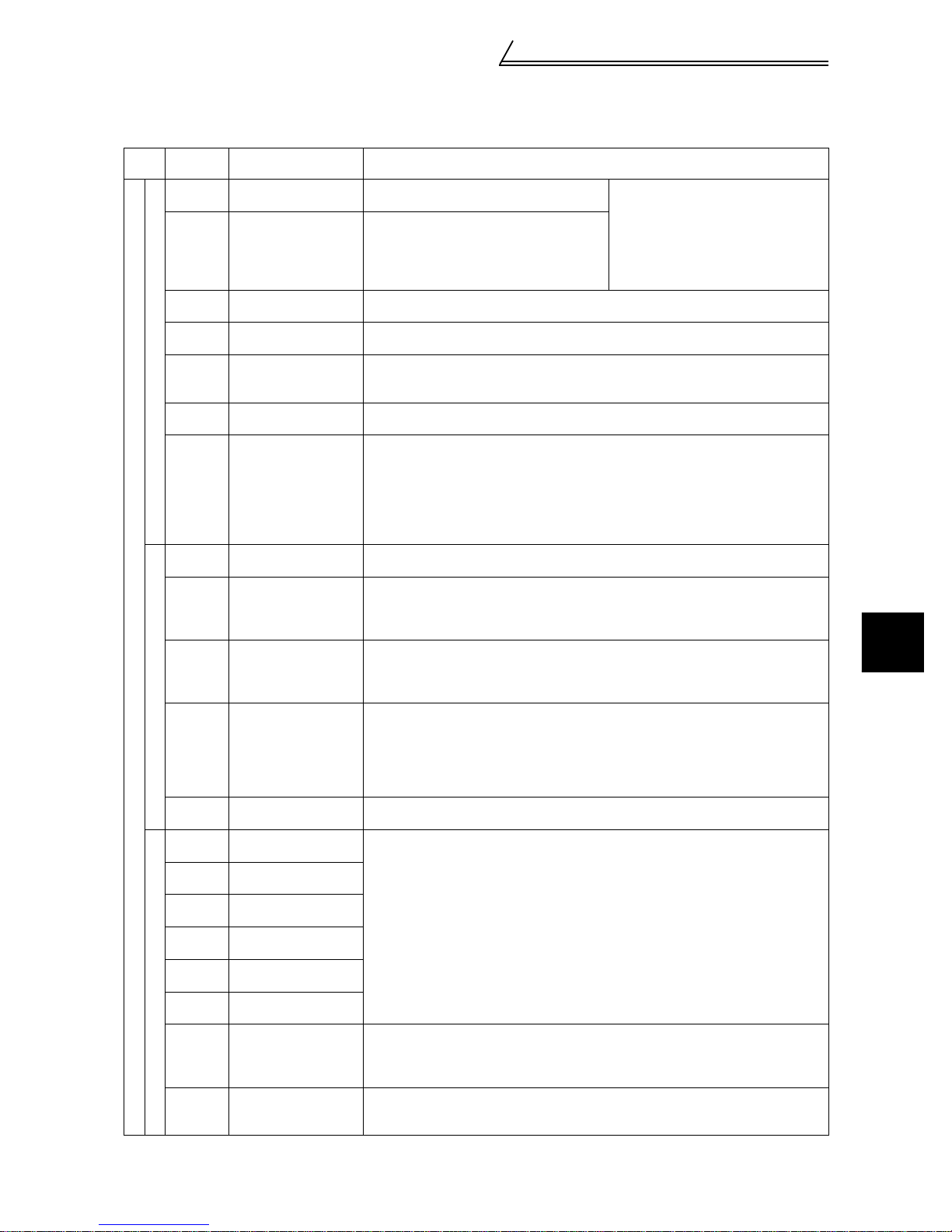
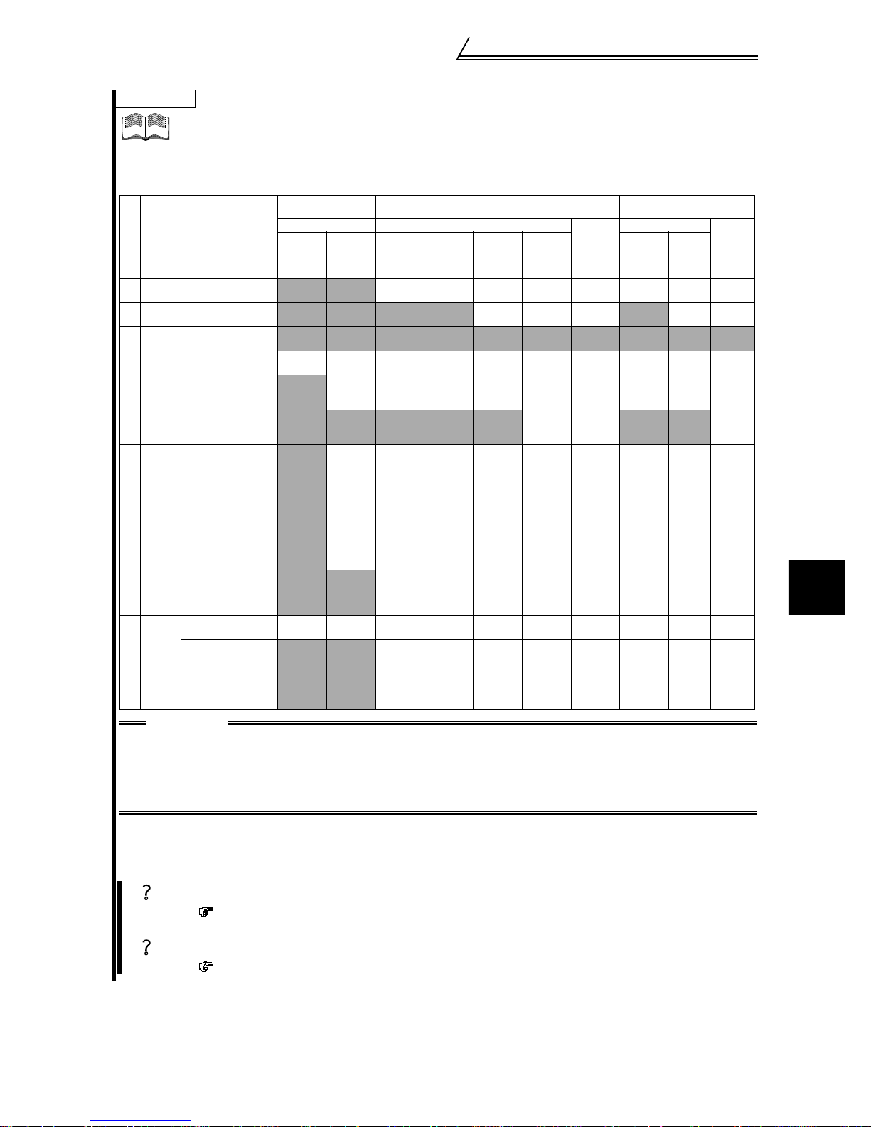
<At-a-glance guide to motor setting>
Dedicated Motor Standard Motor
No. Item
Motor
1
setting
Offline
2
tuning
Capacity
3
setting
Number
4
of PLG
pulses
PLG
5
rotation
direction
PLG
power
6
supply
specifi-
cation
PLG
7
output
type
Electronic
8
thermal
relay
Thermal
9
protector
input
Torque
10
charac-
teristic
Parameter,
Jumper Con-
necter, Ter-
minal
Pr. 71 setting
Pr. 80 setting
Pr. 851setting 2048 1000 1024 1024 1024 - - 1024 1024 -
Pr. 852 setting
PLG
power supply
jumper con-
necter on the
back of the
control termi-
nal
Pr. 9 setting
Across
OH-SD
Pr. 876 setting
Pr. 801 setting
1 :1
1 rank
lower
Power
supply
specifi-
cation
Output
circuit
Termi-
nating
resistance
Mitsubishi Mitsubishi
SF-V5R
1500r/min
Description
series
required *
INV
capacity
Motor
capacity
12V 5V 5V 5V 5V - - 5V 5V -
Complimentary
Connect to
the thermal
SF-VR
30 30 0 20 3 to 8 3 to 8 3 to 8 10 13 to 18 13 to 18
Not
1 1 1 1 1--1 1-
No Yes Yes Yes Yes - - Yes Yes -
0 0
1 1000- -00-
1 1
Not
required *
INV
capacity
Motor
capacity
Differential Differential Differential Differential - - Differential
Connect to
the thermal
SF-JR (with PLG)
(2, 4, 6P)-
2.2kW to
55kW
Not
required *
INV
capacity
Motor
capacity
Rated
inverter
current
Open Open Open - - Open Open -
0 or 1
(Selection
is
required)
(4P)-
1.5kW or
less
required *
INV
capacity
Motor
capacity
Rated
inverter
current
0 or 1
(Selection
required)
SF-HR
(with PLG)
Not
Required Required Required
capacity
capacity
(Selection
is
required)
INV
Motor
Rated
inverter
current
0 or 1
is
(with PLG)
capacity
capacity
(Selection
required)
Others
INV
Motor
0 or 1
Other
manufac-
turer
(with PLG)
INV
capacity
Motor
capacity
--
0 or 1
(Selection
is
is
required)
CAUTION
1. Set number of motor poles in Pr.81.
2. For -, make setting according to the motor used.
3. The half-tone screened cells are factory set.
4. Check the power supply specification of PLG and change a jumper connecter.
5. *:Perform offline auto tuning (mode without rotation) for the wiring length to be reflected on the control when the wiring length is long (30m or longer as reference).)
<When using other manufacturers’ motors>
offline auto tuning (rotation mode) is necessary. Perform offline auto tuning with the motor alone before
connecting a load. If higher torque accuracy is required, perform online auto tuning next.
Constant-torque Motor
(with PLG)
Mitsubishi
SF-HRCA
(4P) (with
required *
(Selection
required)
PLG)
Not
INV
capacity
Motor
capacity
Rated
inverter
current
0 or 1
is
SF-JRCA
(with
PLG)
Required Required
INV
capacity
Motor
capacity
Differen-
tial
Rated
inverter
current
0 or 1
(Selec-
tion
is
required)
Other
manufac-
turer
INV
capacity
Motor
capacity
-
-
0 or 1
(Selection
is
required)
2
INSTALLATION AND WIRING
Offline auto tuning
The inverter measures necessary motor circuit constant and stores it to improve low speed
torque.
Online auto tuning
High torque accuracy corresponding to the motor temperature variation is available.
20

Precautions for use of the vector inverter
2.4 Precautions for use of the vector inverter
The FR-V500 series is a highly reliable product, but incorrect peripheral circuit making or operation/handling
method may shorten the product life or damage the product.
Before starting operation, always recheck the following items.
(1) Use insulation-sleeved crimping terminals for the power supply and motor cables.
(2) Power must not be applied to th e output termina ls (U, V, W) of the inverter. Otherwise the inverter will be damaged.
(3) After wiring, wire off-cuts must not be left in the inverter.
Wire off-cuts can cause an alarm, fault or malfunction. Always keep the inverter clean.
When drilling mounting holes in a control box or the like, use care not to allow chips etc. to enter the inverter.
(4) Wire the cables of the recommended size to make a voltage drop 2% or less.
If the wiring distance is long between the inverter and motor, a main circuit cable voltage drop will cause the
motor torque to decrease especially at the output of a high frequency.
Refer to page 11 for the recommended wire sizes.
(5) The overall wiring length should be 100m maximum.
Especially for long distance wiring, the fast-response current restriction function may be reduced or the equipment connected to the secondary side may malfunction or become faulty under the influe nce of a c harging current due to the stray capacity of the wiring. Therefore, note the overall wiring length.
(6) Electromagnetic wave interference
The input/output (main circuit) of the inverter includes harmonic components, which may interfere with the communication devices (such as AM r adios ) used nea r t he inverte r. In this case, install th e op tion al FR- BIF r adio n oise f ilter
(for use in the input side o nly) or FR- BSF01 or FR- BLF li ne noi se fi lter t o mi nimi ze inte rfer en ce.
(7) Do not install a power factor corr ection capacitor, surge suppressor or radio noise filter (FR-BIF option) in the
output side of the inverter.
This will cause the inverter to trip or the capacitor and surge suppressor to be damaged. If any of the above devices is
installed, immediately remove it. (When the FR-BIF radio noise filter is connected, switching power off during motor
operation may result in E. UVT . In this case, connect the radio noise filter in the primary side of the magnetic contactor.)
(8) When rewiring after operation, switch power off, wait for more than 10 minutes, and then make sure that the
voltage is zero using a tester, etc. For some time after power-off, there is a dangerous voltage in the capacitor.
(9) A short circuit or earth (ground) fault in the inverter output side may damage the inverter modules.
• Fully check the insulation resistance of the circuit prior to inverter operation since repeated short circuits
caused by peripheral circuit inadequacy or an earth (ground) fault caused by wiring inadequacy or reduced
motor insulation resistance may damage the inverter modules.
• Fully check the to-earth (ground) insulat ion and inter-phas e insulation of th e inverter secon dary side before power-on.
Especially for an old motor or use in hostile atmosphere, securely check the motor insulation resistance etc.
(10) Do not use the inverter power supply side magnetic contactor to start/stop the inverter.
Always use the start signal (turn on/off terminals STF, STR-SD) to start/stop the inverter. (Refer to page 7.)
(11) Across the P and PR terminals, connect only an external regenerative brake discharge resistor.
Do not connect a mechanical brake.
(12) Do not apply a voltage higher than the permissible voltage to the inverter I/O signal circuits.
Application (contact) of a voltage higher than the permissible voltage to the inverter I/O signal circuits or opposite polarity may damage the I/O devices. Especially check the wiring to prevent the speed setting potentiometer from being connected incorrectly to short terminals 10E-5.
(13) Use of single-phase power supply
Do not use single-phase power input.
(14) Precautions for use of any motor other than the dedicated motor (SF-V5R) or standard motor with PLG (SF-
JRwith PLG)
a)Vector control cannot be exercised without PLG.
b)Connect the PLG directly to the backlash-free motor shaft.
(15) Since the rated voltage differs from the commercial power supply voltage, the dedicated motor cannot perform
commercial power supply-inverter switchover operation.
Motor Rated Voltage
SF-V5R
SF-V5RH
3.7kW or less 170V
5.5kW or more 160V
3.7kW or less 340V
5.5kW or more 320V
21
Checks prior to test run
3 RUN AND OPERATION
3.1 Checks prior to test run
Installation check
Check that the inverter is installed correctly in a correct place. (Refer to page 6.)
Wiring check
Check that wiring is correct. (Refer to page 7.)
3.2 Basic operation (Speed setting, run, speed meter adjustment)
3.2.1 Setting the speed and running the motor
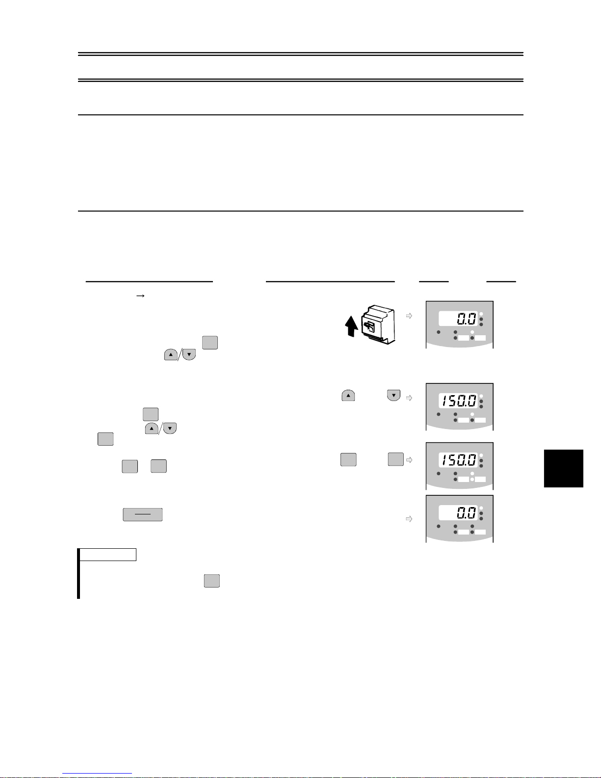
(1) Choosing PU operation mode (operation from the operation panel (FR-DU04-1)) and run-
ning at 150r/min
Operation
1.
Power on Operation mode check
The external operation mode (EXT) is selected when
switching power on with factory setting.
Make sure that the operation command indication "PU" is lit.
If it does not appear, press to choose the operation
MODE
ON
Display
-1
FR-DU04
MON EXT PU
CONTROL PANE L
REV FWD
Hz/r
A
V
mode, and press to choose the PU operation mode.
When the desired result is not obtained, set the PU operation
mode in Pr.79.
2.
Running speed setting
Set the running speed to 150r/min.
First, press to choose the speed setting mode.
MODE
(or)
FR-DU04
CONTROL PANE L
-1
MON EXT PU
REV FWD
Hz/r
A
V
Then, press to change the setting, and press
SET
to write the value.)
Start
3.
Press or .
FWD
REV
The motor starts. The mode is automatically switched
FWD
(or)
FR-DU04
REV
CONTROL PANE L
-1
MON EXT PU
REV FWD
Hz/r
A
V
to the monitoring mode and the output speed is displayed.
Stop
4.
Press .
STOP
RESET
The motor is decelerated to a stop.
FR-DU04
CONTROL PANE L
-1
MON EXT PU
REV FWD
Hz/r
A
V
REMARKS
• The operation speed can be changed by changing the preset speed during operation following the steps 2 an d 3 above.
• For monitor disp la y changes by , refer to page 27.
• To select the PU operation mode in Pr.79 "operation mode selection", set "1" in the parameter. Refer to page 52 for details.
MODE
3
RUN AND OPERATION
22
Basic operation (Speed setting, run,
speed meter adjustment)
PU jog operation
!
Hold down or
FWD
REV
to perform operation, and release it to stop.
1)Set Pr. 15 "jog speed setting" and Pr. 16 "jog acceleration/deceleration time".
2)Set PU jog operation. (Press to select the operation mode and press to switch to PU jog opera-
MODE
tion.)
3)Hold down the or key to perform operation.
FWD
REV
(If the motor remains stopped, check Pr. 13 "starting speed". The motor will not start if its setting is lower than
the starting speed.)
REMARKS
• If the motor does not rotate ⇒ ·Checki ng the PLG jumper connector (Refer to page12.)
• When you want to set th e speed to higher than 1500r/min, set Pr. 1 "maximum speed". (Refer to page 51.)
·Checking the phase sequence of the PLG cable (Refer to page 12.)
·For other cases, refer to Troubleshoo t ing on p age 82.
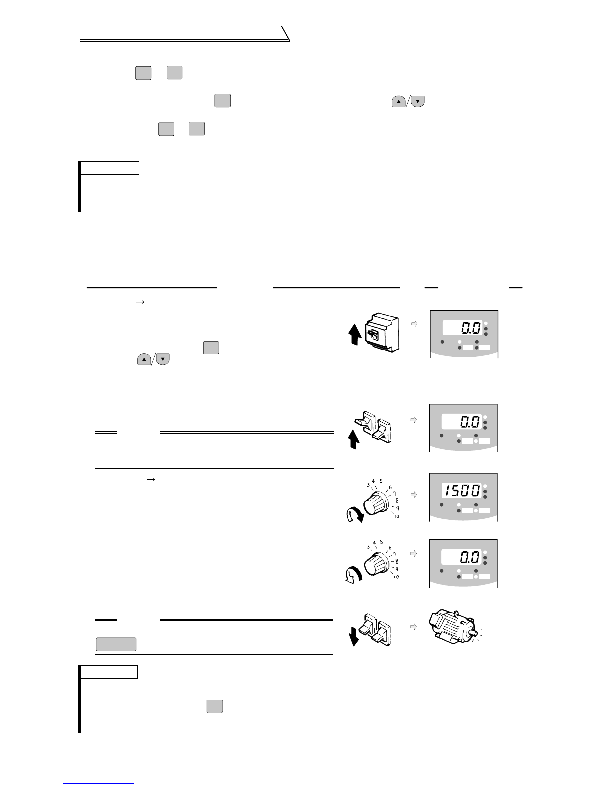
(2) Choosing external operation mode (operation using external speed setting potentiome-
ter and external start signals)
Running at 1500 r/min
!
•Operation command : start signals connected outside
•Speed setting : speed setting potentiometer connected outside
Operation Display
Power on Operation mode check
1.
The external operation (EXT) is selected when switching
power on with factory setting. Make sure that the operation
command indication "EXT" is lit.
If it does not appear, press to choose the operation mode,
MODE
and press to choose the external (EXT) operation mode.
When the desired result is not obtained, set the external
operation mode in Pr.79.
Start
2.
Turn on the start switch (STF or STR).
The operation status indication FWD or REV flickers.
CAUTION
The motor does not start if both t he forward and reverse
rotation switches are turned on. If both switches are
turned on during operation, the motor decelerates to a stop.
Acceleration Constant speed
3.
Slowly turn the potentiometer (speed setting potentiometer)
connected to across terminals 2-5 full clockwise.
The speed shown on the display increases gradually to
1500r/min.
Deceleration
4.
Slowly turn the potentiometer (speed setting potentiometer)
connected to across terminals 2-5 full counterclockwise.
The speed shown on the display decreases gradually to 0r/min.
The motor stops running.
5.
Stop
Turn off the star t switch (STF or STR).
CAUTION
When Pr. 75 "PU stop selecti on"= "14 to 17",
STOP
RESET
is valid.
ON
Forward
rotation
Forward
rotation
OFF
Reverse
rotation
Reverse
rotation
FR-DU04
FR-DU04
FR-DU04
FR-DU04
CONTROL PANE L
-1
MON EXT PU
REV FWD
CONTROL PANE L
-1
MON EXT PU
REV FWD
CONTROL PANE L
-1
MON EXT PU
REV FWD
CONTROL PANE L
-1
MON EXT PU
REV FWD
Stop
Hz/r
A
V
Hz/r
A
V
Hz/r
A
V
Hz/r
A
V
REMARKS
• The operation spee d of the external potentiome ter can be adju sted in Pr. 902 and Pr. 903 (bias and gain of the speed setting terminal). (Refer to page 47.)
• For monitor disp la y changes by , refer to page
• To select the external operation mode in Pr. 79 "operation mode selection", set "2" in the parameter. Refer to page 52 for
details.
MODE
27
.
23
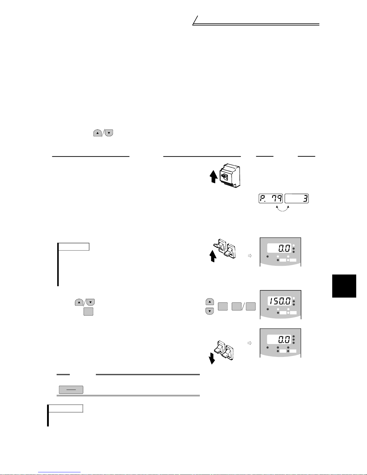
Basic operation (Speed setting, run,
speed meter adjustment)
External jog operation
!
Keep the start switch (STF or STR) on to perform operation, and turn it off to stop.
1)Set Pr. 15 "jog speed setting" and Pr. 16 "jog acceleration/deceleration time".
2)Select the external operation mode.
3)Switch on the jog signal. Keep the start switch (STF or STR) on to perform operation.
Assign the terminal used for the jog signal in any of Pr. 180 to Pr. 183 and Pr. 187
(input terminal function selection). (Refer to page 61.)
(3) Choosing external/PU combined operation mode 1 (operation using the external start
signal and operation panel)
! When setting the start signals from outside inverter (e.g. switches or relays) and the run-
ning speed from the operation panel (Pr. 79=3)
•Operation command : start signal connected outside
•Speed setting : of PU or multi-speed command (multi-speed command has priority)
For multi-speed command, refer to Pr.4 to Pr.6 on page 50.
Operation
1.
Power on
Switch power on.
Operation mode selection
2.
Set "3" in Pr. 79 "operation mode selection".
(Refer to page 52 for details of Pr.79.)
The combined operation mode is selected and the operation
status indication "EXT" and "PU" are lit.
Start
3.
Turn on the start switch (STF or STR).
The operation status indication "FWD" or "REV" is lit.
REMARKS
• The motor does not start if both the forward and
reverse rotation switches are turned on. If both
switches are turned on during operation, the motor
decelerates to a stop.
• Set the speed in the speed setting mode
4.
Running speed setting
Using , of PU, set the running speed to 150r/min
and press .
SET
The operation command indication FWD or REV is lit.
Stop
5.
Turn off the start switch (STF or STR).
The motor decelerates to stop.
The operation status indication "FWD" or "REV" is lit.
(Refer to page 27.).
ON
Forward
rotation
ON
SET REV FWD
Forward
rotation
Reverse
rotation
Reverse
rotation
Display
-1
FR-DU04
MON EXT PU
FR-DU04
MON EXT PU
-1
FR-DU04
MON EXT PU
REV FWD
-1
REV FWD
REV FWD
Flicker
CONTROL PANEL
CONTROL PANEL
CONTROL PANEL
Hz/r
A
V
3
Hz/r
A
V
Hz/r
A
V
CAUTION
When Pr. 75 "PU stop selection" = "14 to 17",
STOP
RESET
is valid.
REMARKS
When setting the start signal from the PU and speed setting signal from outside inverter, set "4" (combined operation mode 2
in Pr.79 "operation mode select i on".
OFF
RUN AND OPERATION
)
24
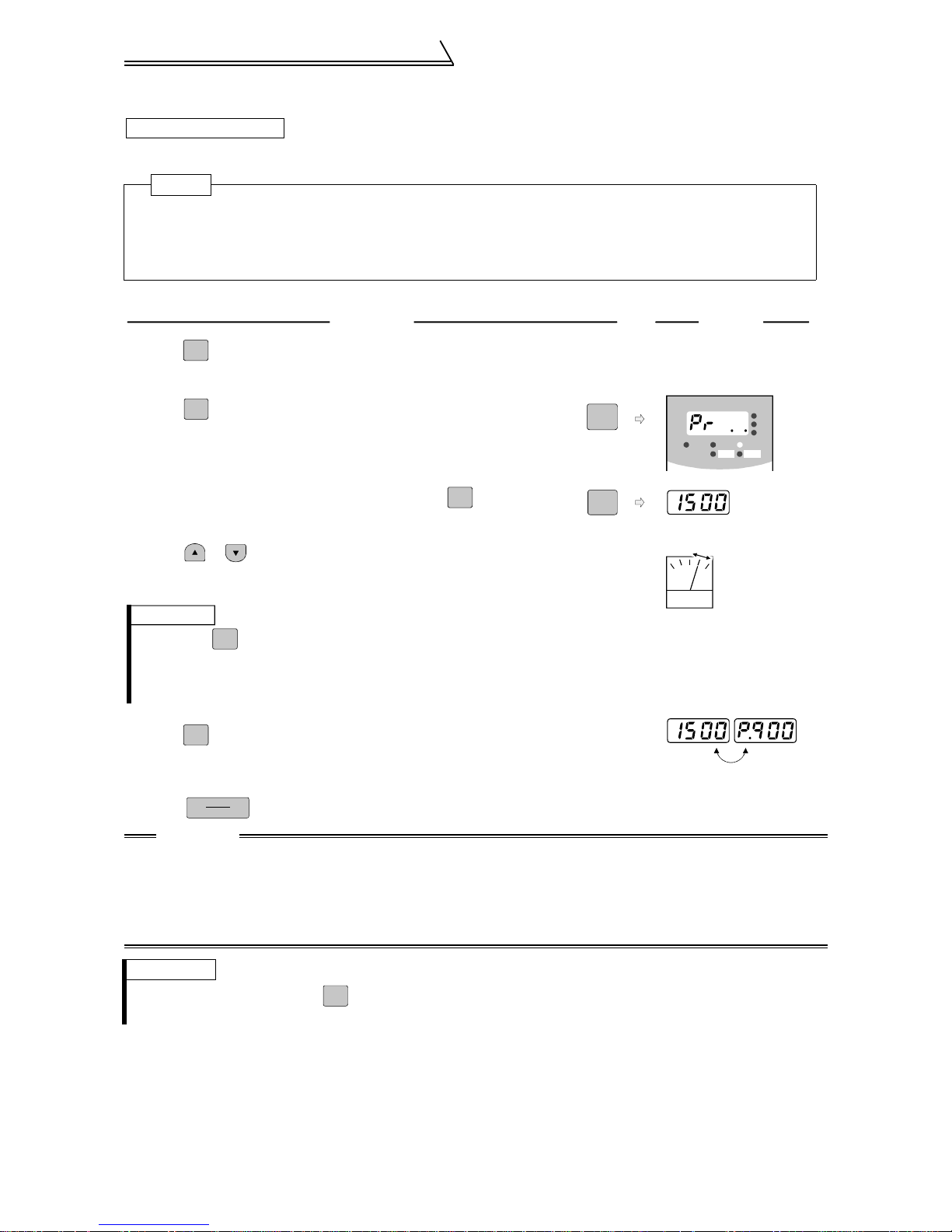
Basic operation (Speed setting, run,
speed meter adjustment)
3.2.2 Adjustment (calibration) of speed meter (meter)
Changing example
At the preset speed of 1500r/min, make adjustment so that the meter (analog meter)
deflects to full-scale. Calibrate the DA1 terminal (±10V).(in PU operation mode)
POINT
• Pr. 900 "DA1 terminal calibration" can be read by setting "1" (extended function parameter enable) in
Pr. 160 "extended function selection".
• Set Pr. 900 "DA1 terminal calibration".
• Set any of "1 to 3, 5 to 12, 17, 18, 21, 32 to 34 and 36" in Pr. 54 "DA1 terminal function selection" to
output a signal to the terminal DA1. (Refer to page 56)
Operation
FWD
Press to operate the inverter. (It is not necessary to
1.
Display
connect a m o t o r.)
2.
3.
MODE
Press to select the parameter setting mode.
Display the present operation speed by pressing to
SET
MODE
SET
FR-DU04
MON EXT PU
REV FW D
Hz¤r
A
V
CONTROL PANEL
-1
read Pr. 900.
Press or to adjust the meter pointer to
4.
a predetermined position. (Depending on the setting,
(Analog voltage meter)
it may take some time until the pointer moves.)
REMARKS
1. Pressing to start reverse rotation operation will move the meter pointer
REV
reversely (in the negative direction).
2. The terminal DA1 output will also keep displaying the monitor when the
inverter stops due to an alarm.
5.
SET
Press for about 1.5s.
This completes the setting.
Flicker ...
Press to stop the inverter.
6.
STOP
RESET
Parameter setting complete!!
CAUTION
1. When the speed meter is connected across terminals DA1-5 to monitor the speed, the outp ut of ter-
minal DA1 is saturated if the maximum output speed reaches or exceeds 1500r/min, with the factory
setting unchanged. Hence, the setting of Pr. 55 "speed monitoring reference" must be changed to the
maximum output speed. (Refer to page 56.)
2. Terminal DA2 can be adjusted in Pr. 901
3. For operation from the parameter unit (FR-PU04V), refer to the instruction manual of the FR-PU04V.
REMARKS
• For monitor disp la y changes by , refer to page 27.
• Calibration can be made also during external operation.
MODE
25
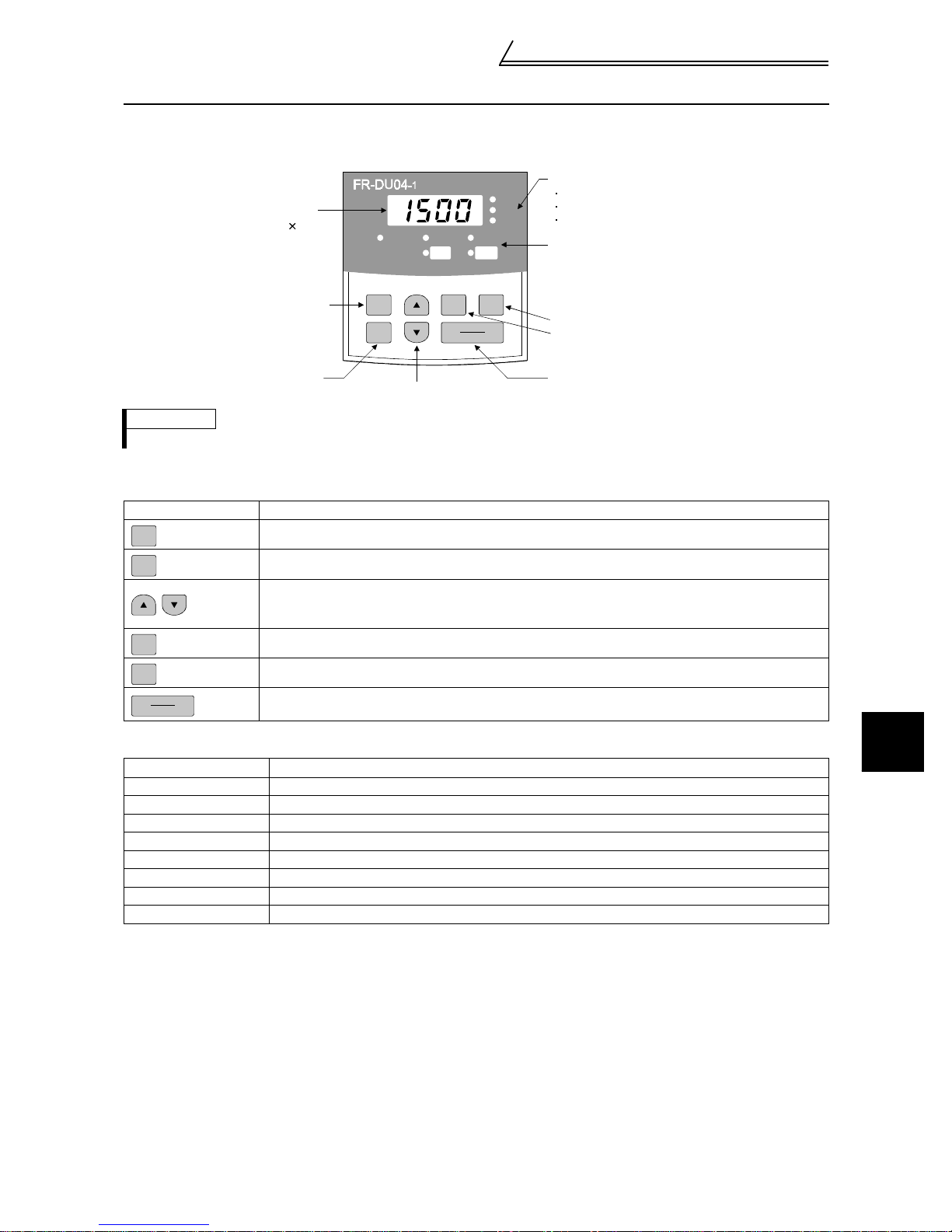
Names and functions of the opera-
tion panel
3.3 Names and functions of the operation panel
With the operation panel (FR-DU04-1), you can perform operation, set the speed, monitor the operation command
display, set parameters, display an error, and copy parameters.
isplay
ED 4 digits
Mode key
MON EXT PU
MODE
SET
etting key
Up/down keys
REMARKS
The ON of the LED is indicated by", and OFF by!.
Key indication
!
Key Description
MODE
SET
Select the operation mode or setting mode.
Determine the speed or pa ra meter setting.
• Used to increase or decrease the running speed consecutively. Hold down this key to change the
speed.
• Press thi s key in the setting mode to change the param et er set t in g consecutively.
FWD
Forward rotation comm and key.
CONTROL PANEL
FWD
REV
REV FWD
STOP
RESET
Hz/r
A
V
Unit indication
Hz/r (motor speed)
A (current)
V (voltage)
Operation status indication
Forward rotation key
Reverse rotation key
Stop/reset key
REV
STOP
RESET
Unit indication, operation status indication
!
Reverse rotation comman d key.
• Used to stop operation.
• Used to reset the inverter when the protective function (major fault) is activated to stop the output.
Indication Description
Hz/r Lit to indicate the outpu t s peed.
A Lit to indicate the current.
V Lit to indicate the voltage.
MON Lit in the monitor display mode.
PU Lit in the PU operation mode.
EXT Lit in the external operation mode.
FWD Flickers during forward rotation.
REV Flickers during reverse rotation.
3
RUN AND OPERATION
26
 Loading...