

Mitsubishi FR-V520-37K, FR-V540-15K, FR-V520-55K, FR-V520-7.5K, FR-V520-11K Instruction Manual
...
6
5
4
2
1
3
VECTOR INVERTER
FR-V
500
INSTRUCTION MANUAL (BASIC)
FR-V520-1.5K to 55K
FR-V540-1.5K to 55K
FR-V500
VECTOR INVERTER INSTRUCTION MANUAL (BASIC)
2
1
3
4
5
6
7
Contents
OUTLINE......................................................................................................1
1.1 Basic configuration and connection of peripheral devices........................................2
1.2 Structure...................................................................................................................4
INSTALLATION AND WIRING.....................................................................6
2.1 Installation of the inverter .........................................................................................6
2.2 Connection diagram, PLG cable, PU connector.......................................................7
2.3 Setting the motor ....................................................................................................19
2.4 Precautions for use of the vector inverter...............................................................21
RUN AND OPERATION.............................................................................22
3.1 Checks prior to test run ..........................................................................................22
3.2 Basic operation (Speed setting, run, speed meter adjustment)..............................22
3.3 Names and functions of the operation panel..........................................................26
CONTROL..................................................................................................32
4.1 Speed control operation ........................................................ ...... ....... ...... ....... ...... . 32
4.2 Torque control operation ........................................................................................36
4.3 Position control operation.......................................................................................41
4.4 Control mode switchover timing .............................................................................42
4.5 Easy gain tuning.....................................................................................................43
4.6 Online auto tuning ....................................................................... ....... ...... ....... .......46
4.7 Biases and gains of speed setting terminals
(Pr. 902 to Pr. 905, Pr. 917 to Pr. 920)...................................................................47
PARAMETERS...........................................................................................50
5.1 Function list (Simple mode parameters).................................................................50
5.2 Function list (Extended function parameters).........................................................54
ERRORS AND PROTECTIVE FUNCTIONS..............................................70
6.1 Errors (Alarms) ......................... ...... ...... ....... ...... ....... ...... ....... ...... ....... ....................70
6.2 Correspondences between digital and actual characters.......................................80
6.3 Resetting the inverter ..................................................... ....... ...... ....... ...... ....... ...... .80
6.4 Troubleshooting......................................................................................................82
6.5 Precautions for maintenance and inspection..........................................................93
SPECIFICATIONS .....................................................................................99
Thank you for choosing this Mitsubishi Vector Inverter.
If this is the first time for you to use the FR-V500 series, please read through this Instruction Manual (basic) carefully to use the inverter safely.
When you are going to use the inverter for higher-leveled applications, please request the separately available
FR-V500 Instruction Manual (detailed) [IB(NA)-0600065] from where you purchased the inverter or a Mitsubishi
sales representative.
This Instruction Manual (basic) provides handling information and precautions for use of the equipment.
Please forward this Instruction Manual (basic) to the end user.
This section is specifically about safety matters
Do not attempt to install, operate, maintain or inspect the inverter until you have read through the Instruction
Manual (basic) and app ended do cumen ts car efull y and c an use the equ ipm ent corr ectly. In this Instruction
Manual, the safety instruction levels are classified into "WARNING" and "CAUTION"
.
WARNING
CAUTION
Note that even the CAUTION lev el may lead to a serious cons equence ac cor ding to con ditio ns. Please fo llow the instructions of both levels because they are important to personnel safety.
1. Electric Shock Prevention
Assumes that inco rrect ha ndlin g may c ause h azardou s cond ition s, res ultin g in
death or severe injury.
Assumes that inco rrect ha ndlin g may c ause h azardou s cond ition s, res ultin g in
medium or slight injury, or may cause physical damage only.
WARNING
!Whi le power is on or when the inver ter is running, do not open the front cover. You may get an electric
shock.
!Do not run the inverter wit h the fron t cover remov ed. Otherwi se, you may access the exposed h igh-volt-
age terminals or the charging part of the circuitr y and get an electr ic shock .
!If power is off, do not remove the front cover except for wiring or periodic inspection. You may access the
charged inverter circuits and get an electric shock.
!Before starting wiring or inspection, check that power lamp display is turned off and check for residual volt-
ages with a meter etc. more than 10 minutes after power-off.
!Earth (Ground) the inverter.
!Any person wh o is involv ed in wir ing or inspe ction of this equipment s hould be fu lly compe tent to do the
work.
!Always install the inverter before wiring. Otherwise, you may get an electric shock or be injured.
!Perform setting dial and key operations with dry hands to prevent an electric shock.
!Do not subject the cables to sc ratches, excessive str ess, heavy loads or pinc hing. Otherwise, you may
get an electric shock.
!Do no t change the cooling fan while power is on. It i s dan ger ou s t o c han ge the co oli ng fan whi le powe r is
on.
2. Fire Prevention
CAUTION
!Mount the inverter to incombustible material. Mounting it to or near combustible material can cause a fire.
!If the inverter has become faulty, switch off the inverter power. A continuous flow of large cur rent could
cause a fire.
!Do not connect a resistor directly to the DC terminals P, N. This could cause a fire.
3.Injury Prevention
CAUTION
!Apply only the voltage specified in the instruction manual to each terminal to prevent damage etc.
!Ensure that the cables are connected to the correct terminals. Otherwise damage etc. may occur.
!Always make sure that polarity is correct to prevent damage etc.
!While power is on and for some time after power-off, do not touch the inverter or brake resistor as they are
hot and you may get burnt.
A-1
4. Additional Instructions
Also note the following points to prevent an accidental failure, injury, electric shock, etc.
1) Tra nsportation and installation
CAUTION
!When carrying products, use correct lifting gear to prevent injury.
!Do not stack the inverter boxes higher than the number recommended.
!Ensure that installation position and material can withstand the weight of the inverter.
!Do not operate if the inverter is damaged or has parts missing.
!When carrying the inverter, do not hold it by the front cover or setting dial; it may fall off or fail.
!Do not stand or rest heavy objects on the inverter.
!Check the inverter mounting orientation is correct.
!Prevent screws, wire fragments, other conductive bodies, oil or other flammable substances from entering
the inverter.
!Do not drop the inverter, or subject it to impact
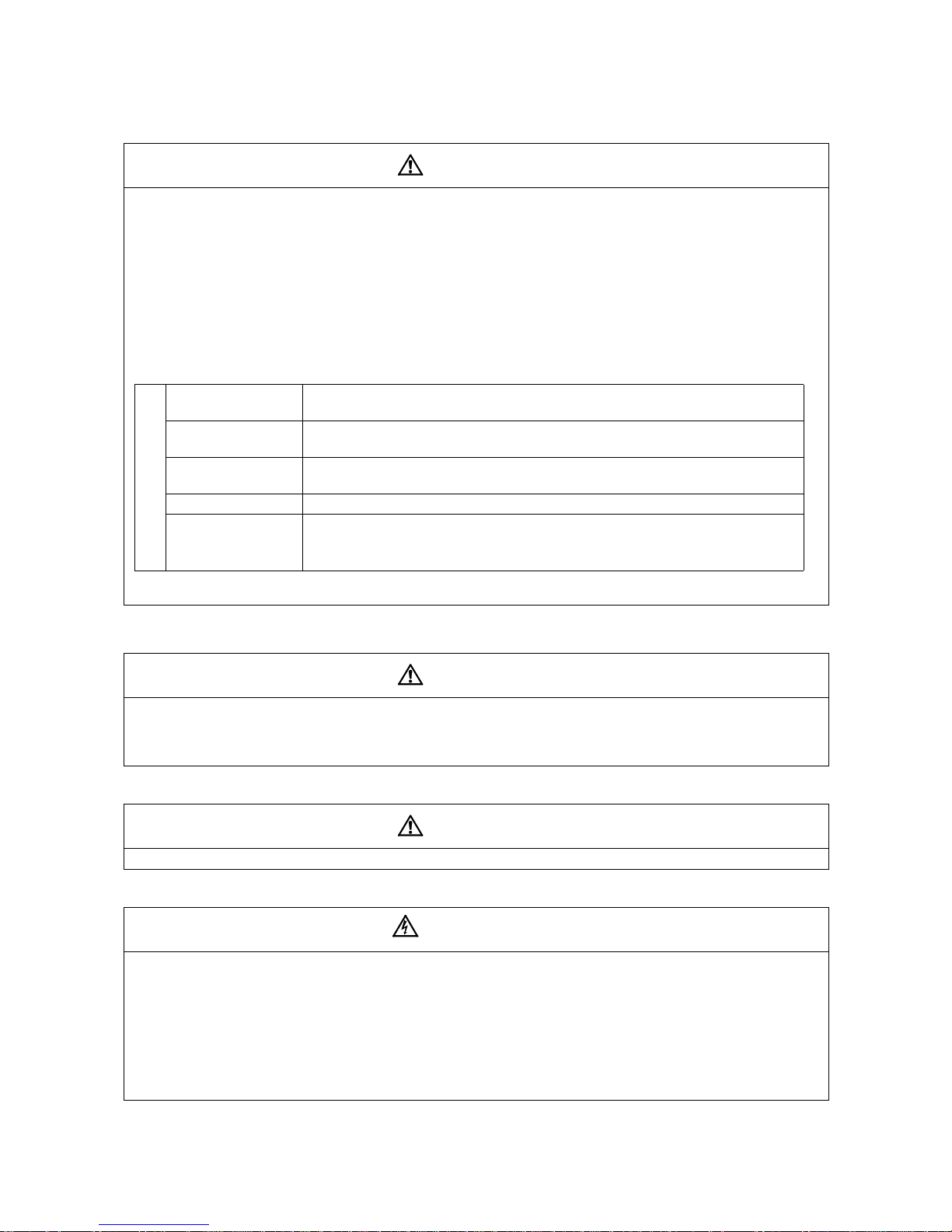
!Use the inverter under the following environmental conditions:
Ambient temperature
Ambient
humidity
Storage
ture
Ambience Indoors (free from corrosive gas, flammable gas, oil mist, dust and dirt)
Environment
Altitude, vibration
*
Temperature applicable for a short time, e.g. in transit.
tempera-
-10°C to +50°C (non-freezing)
90%RH or less (non-condensing)
-20°C to +65°C*
Maximum 1000m above sea level for standard operation.
After that derate by 3% for every extra 500m up to
2500m (91%). 5.9m/s
2
or less (conforming to JIS C 0040)
2) Wiring
CAUTION
!Do not fit capacit ive equipmen t such as power fac tor correction capacitor, radio noise filter or surge sup-
pressor to the output of the inverter.
!The connecti on orien tation of the output cables U, V, W to the motor will affect the direction of rotati on of
the motor.
3) Trial run
CAUTION
!Check all parameters, and ensure that the machine will not be damaged by a sudden start-up.
4) Operation
!When you have chosen the retry function, stay away from the equipment as it will restart suddenly after an
alarm stop.
!The [STOP] key is valid only when the appropriate functi on setting has been made. Prepare an emer-
gency stop switch separately.
!M ake s ur e t hat the sta rt s ign al is off befo re res etti ng the inv erter alarm. A failure to do so ma y restart the
motor suddenly.
!The load used should be a three-phase induction motor only. Connection of any other electrical equipment
to the inverter output may damage the equipment.
!Do not modify the equipment.
WARNING
A-2
CAUTION
!The electronic thermal relay does not guarantee protection of the motor from overheating.
!Do not use a magnetic contactor on the inverter input for frequent starting/stopping of the inverter.
!Use a noi se filte r to reduc e the effect of electro mag net ic interfe re nc e. Otherwi se near by ele ctron ic equip-
ment may be affected.
!Take measures to suppress harmonic s. Otherwise power fr om the inverter may hea t/damage the power
capacitor and generator.
!When paramet er clea r or all c lear is per formed, each parame ter retu rns to the f actory setting. R e-set the
required parameters before starting operation.
!The inverter can be easily set for high-speed operation. Before changing its setting, fully examine the per-
formances of the motor and machine.
!In addition to the inverter's holding function, install a holding device to ensure safety.
!Befo re running an inverter which ha d been stored for a long period, always perform inspection and tes t
operation. In addition to the inverter's holding function, install a holding device to ensure safety.
5) Emergency stop
CAUTION
!Provide a safety backup such as an emergency brake which will prevent the machine and equipment from
hazardous conditions if the inverter fails.
6) Maintenance, inspection and parts replacement
CAUTION
!Do not carry out a megger (insulation resistance) test on the control circuit of the inverter.
7) Disposing of the inverter
CAUTION
!Treat as industrial waste
8) General instructions
Many of the diagrams and drawing s in this Instruction Ma nual (basic ) show the inverte r without a cover, or
partially open. Never operate the i nverter i n this ma nner. Always replace the cov er and fo llow this In struction Manual (basic) when operating the inverter.
A-3

1 OUTLINE
<Abbreviations>
• DU: Operation panel (FR-DU04-1)
• PU: Operation panel (FR-DU04
• Inverter: Mitsubishi vector inverter FR-V500 series
• FR-V500: Mitsubishi vector inverter FR-V500 series
• Pr.: Parameter number
• PU operation: Operation using the PU (FR-DU04
• External operation: Operation using the control circuit signals
• Combined operation: Operation using both the PU (FR-DU04
• Dedicated motor: SF-V5R
• Standard motor (with PLG): SF-JR
• Constant-torque motor (with PLG): SF-HRCA
Harmonic Suppression Guideline
The "harmonic suppression guideline for household appliances and general-purpose products" was issued by the
Ministry of Economy , T rade and Industry (formerly Ministry of International T r ade and Industry) in September, 1994.
This guideline applies to the 3.7K or less. By installing the power factor improving reactor (FR-BEL or FR-BAL), this
product conforms to the "harmonic suppression technique for transistorized inverters (input current 20A or less)" set
forth by the Japan Electrical Manufactures' Association.
For the 3.7K or more, refer to the Instruction Manual (detailed).
Product check and name of parts
Unpack the inverter and check the capacity plate on the front cover and the rating plate on the inverter side face to
ensure that the product agrees with your order, an accessory L shaped jumper (Refer to page 15 for connection
method.)is included, and the inverter is intact.
) and parameter unit (FR-PU04V)
-1
/FR-PU04V)
-1
Plates
.
/FR-PU04V) and external operation
-1
Rating plate
Inverter type
Input rati ng
Output rating
Serial number
Capacity plate
nverter type
FR
Symbol
Voltage class
Three-phase 200V class
V520
Three-phase 400V class
V540
-
V520
-K
1.5
Inverter
capacity
(kW)
Inverter type Serial number
o. 5 terminal dedicated Lshaped jumper × 1 (supplied)
(1) Front view
POWER lamp
ALARM lamp
.
Operation panel (FR-DU04-1)
Brake resistor* (Fitted to the back)
Accessory cover
Wiring port cover for option
Front cover
Rating plate
Capacity plate
(2) Without front cover
PU Connector
(Provided with modul ar jack
type relay connector)
(For use with RS-485 cable
communication)
Modular jack type relay
connector compartment
Inboard option mounting positions
Control circuit terminal block
Main circuit terminal block
Wiring cover
*The 5.5K or less inverter is equipped with a built-in brake resistor and the 15K or less inverter is equipped
with a built-in brake transistor.
1
Basic configuration and connection
of peripheral devices
1.1 Basic configuration and connection of peripheral devices
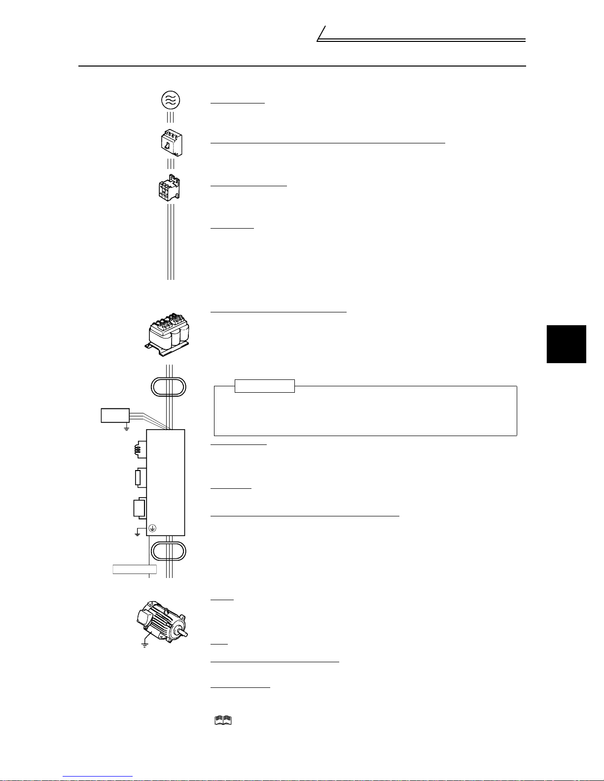
1.1.1 Basic configuration
Power supply
Use within the permissible power supply specifications of the inverter. (Refer to page 99. )
AC reactor
(FR-BAL)
Line noise
filter
Radio noise
filter
Power factor
improvement
reactor
Brake resister
(FR-ABR)
Brake unit
Line noise
filter
PLG cable
(NFB)
or
(ELB)
(MC)
P
P1
P
PR
P
N
Earth(Ground)
RS
Inverter
FR-V500
T
No-fuse breaker (NFB) or earth leakage circuit braker (ELB)
The breaker mus t be selected carefully since a n in-rush current flows in the inverter at
power-on. (Refer to page 3. )
Magnetic contactor
Install the magnetic contactor to ensure safety. (For details, refer to the Instruction Manual
(detailed).)
Do not use this magnetic contactor to start and stop the inverter. Doing so will cause the
inverter life to be shorten.(Refer to page 3.)
Noise filter
Install a noise filter to reduce t he m agnetic noise generated from the inverter.
(Refer to the instruction manual of each option for details.)
• Line noise filter (FR-BSF01) (FR-BLF)
Effective in the range from about 1MHz to 10MHz. When more wires are passed
through, a more e ffective result can be obtained.(Note that the number of wires run
through is limited when fitting to the output side.)
• Radio noise filter (FR-BIF)
Effective in reducing the no ises i n th e AM radi o f reque ncy b and. D edica ted filter f or the
input side.
Power factor improvement reactor
Reactors must be us ed when the power factor is to be improved or whe n the inverter is
installed near a large power sup ply syst em ( 1000k VA or more and wiring dista nce is within
10m). The inverter may be damaged if you do not use reactors.
Make selection carefu lly. (Refer to page 3.)
(Refer to the instruction manual of each option for details.)
• DC reactor (FR-BEL), AC reactor (FR-BAL)
(Caution) Remove the ju m per s across terminals P-P1 to connect to the PC reacto r.
Inverter
The life of the inverter is influenced by ambient temperature. The ambient
temperature should be as low as possible within the permissible range. This must be
noted especially when the inverter is installed in an enclosure. (Refer to page 6.)
Wrong wiring might lead to damage of the inverter. The control signal lines must be
kept fully away from the main circuit to protect them from noise. (Refer to page 7.)
Brake resistor
(Refer to the instruction manual of each option for details)
(Caution) •Remove the jumpers across terminals PR-PX to connect to the inverter.
•Set "1" in Pr. 30 "regenerative function selection".
•Set "10%" in Pr. 70 "special regenerative brake duty".
Brake unit
(Refer to the instruction manual of each option for details)
(Caution) Remove the ju m pers across terminals PR-PX to connect to th e i nverter.
Power regeneration common converter (FR-CV)
• (Refer to the ins truc t io n m anual of each option for details.)
(Caution) •Remove the jumpers across terminals R-R1 and S-S1.
•For a terminal to be connected to the RDYB signal of the FR-CV, set "10" (X10
signal) in any of Pr. 1 80 t o Pr. 183 and Pr. 187(input ter m i nal function selection).
•Set "2" in Pr. 30 "regenerative function selection".
•Select the converter one rank higher in capacity than the inverter.
Selection example: F R-V520-7.5K→FR-CV-11K, FR-V520-15K→FR-CV-18.5K
(When connecting two inverters to one FR-CV, the capacity is 11K + 18.5K =
29.5K. Therefore, select FR-CV-30K.)
Motor
Dedicated motor (Refer to page 99.)
!
This is a highly environmentally-resistant motor based on a totally-enclosed squirrelcage induction motor designed for the vector inverter. Select the motor that matches the
inverter capacity.
PLG
For the PLG dedicated motor, refer to page 12.
Devices connected to the output
Do not install a power factor correction capacitor, surge suppressor or radio noise filter (FRBIF option) in the output side of the inverter.
Earth (Ground)
To prevent an electric shock, always earth (ground) the motor and inverter. For reduction of
induction noise from the pow er line of the inverter, it is recommended to wire the earth
(ground) cable by return ing it to th e ear t h (g ro und) terminal of the inverter.
( For details of noise reducti on t echniques, refer to the Instruction Manual (det ai led) .
1
OUTLINE
2
Basic configuration and connection
of peripheral devices
Caution
• Do not fit capacitive equipment such as power factor correction capacitor, radio noise filter (FR-BIF
option) or surge suppressor to the output side of the inverter. This will cause the inverter to trip or power
factor correction capacitor and surge suppressor to be damaged. If any of the above devices are connected, imme diately remove them. If the FR-BIF radio noise filter is connected, switching power off during
motor operation may result in "E.UVT". In this case, connect the radio noise filter on the primary side of
the magnetic contactor.
• Electromagnetic wave interference
The input/output (main circuit) of t he inverter includes h armonic co mponent s, which may in terfere with
the communication devices (such as AM radios) used near the inverter. In this case, install the FR-BIF
optional radio noise filter (for use in the input side only) or FR-BSF01 or FR-BLF line noise filter to minimize interference.
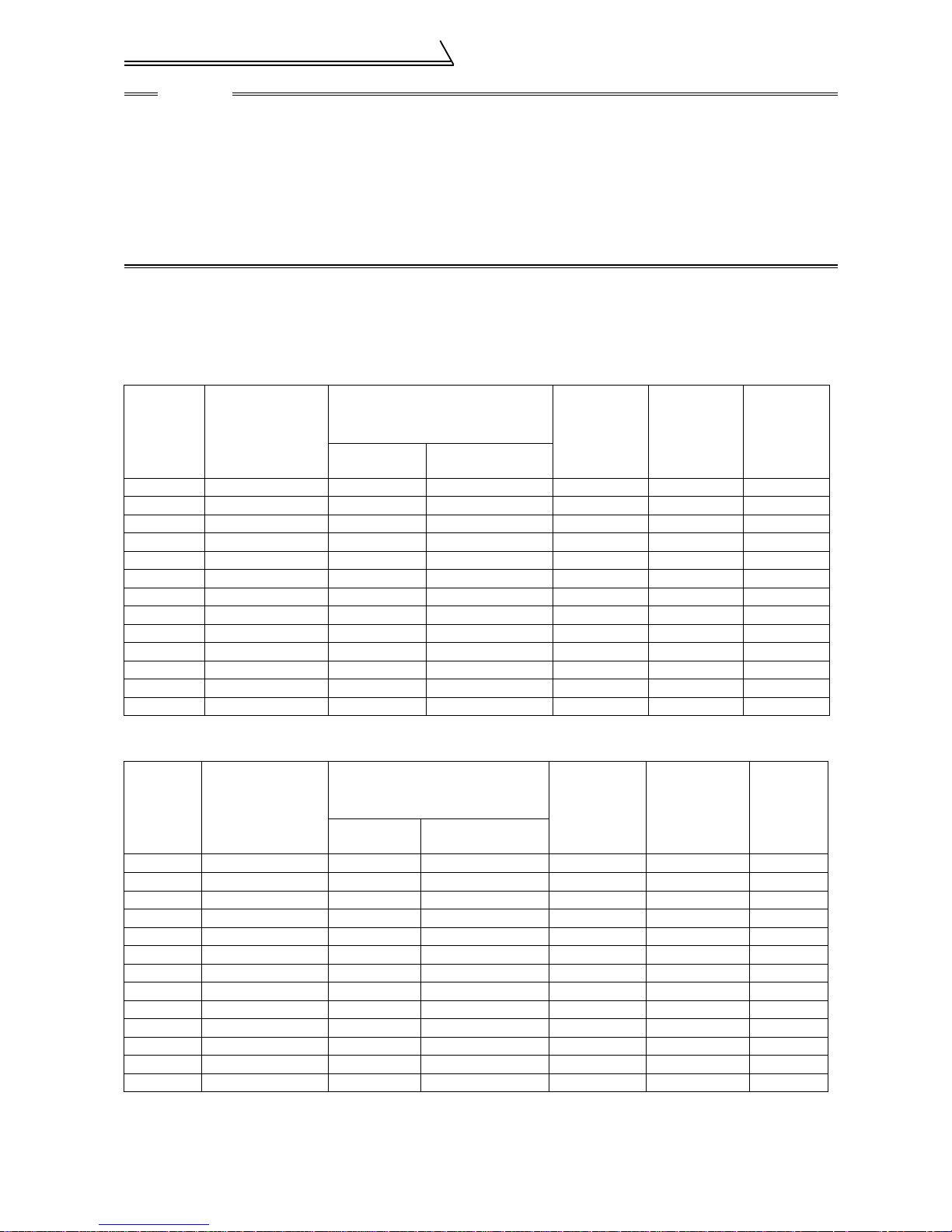
1.1.2 Selection of peripheral devices
Check the capacities of the motor applicable to the inverter you purchased. Refer to the list below and prepare
appropriate peripheral devices.
200V class
No-fuse Breaker
Motor
Output
(kW)
1.5 FR-V520-1.5K 30AF 15A 30AF 15A FR-BAL-1.5K FR-BEL-1.5K S-N10
2.2 FR-V520-2.2K 30AF 20A 30AF 15A FR-BAL-2.2K FR-BEL-2.2K S-N11, N12
3.7 FR-V520-3.7K 30AF 30A 30AF 30A FR-BAL-3.7K FR-BEL-3.7K S-N20
5.5 FR-V520-5.5K 50AF 50A 50AF 40A FR-BAL-5.5K FR-BEL-5.5K S-N25
7.5 FR-V520-7.5K 100AF 60A 50AF 50A FR-BAL-7.5K FR-BEL-7.5K S-N35
11 FR-V520-11K 100AF 75A 100AF 75A FR-BAL-11K FR-BEL-11K S-N50
15 FR-V520-15K 225AF 125A 100A F 100 A FR-BAL-15K FR-BEL-15K S-N65
18.5 FR-V520-18. 5K 225AF 150 A 225AF 125A FR-BAL-22K FR-BEL-18.5K S-N80
22 FR-V520-22K 225AF 175A 225A F 150 A FR-BAL-22K FR-BEL-22K S-N95
30 FR-V520-30K 225AF 225A 225A F 175 A FR-BAL-30K FR-BEL-30K S-N125
37 FR-V520-37K 400AF 250A 225A F 225 A FR-BAL-37K FR-BEL-37K S-N150
45 FR-V520-45K 400AF 300A 400A F 300 A FR-BAL-45K FR-BEL-45K S-N180
55 FR-V520-55K 400AF 400A 400A F 350 A FR-BAL-55K FR-BEL-55K S-N220
Applicable
Inverter
Type
(NFB*1)
or Earth Leakage Cir-
cuit Breaker (ELB
Standard
)
Wi th p o wer fa c tor
improving reactor
Power Factor
Improving AC
Reactor
Power Factor
Improving DC
Reactor
Magnetic
Contactor
(MC)
400V class
No-fuse Breaker
Motor
Output
(kW)
1.5 FR-V540-1.5K 30AF 10A 30AF 10A FR-BAL-H1.5K FR-BEL-H1.5K S-N10
2.2 FR-V540-2.2K 30AF 15A 30AF 10A FR-BAL-H2.2K FR-BEL-H2.2K S-N11, N12
3.7 FR-V540-3.7K 30AF 20A 30AF 15A FR-BAL-H3.7K FR-BEL-H3.7K S-N20
5.5 FR-V540-5.5K 30AF 30A 30AF 20A FR-BAL-H5.5K FR-BEL-H5.5K S-N20
7.5 FR-V540-7.5K 30AF 30A 30AF 30A FR-BAL-H7.5K FR-BEL-H7.5K S-N20
11 FR-V540-11K 50AF 50A 50AF 40A FR-BAL -H11K FR-BEL-H11K S-N20
15 FR-V540-15K 100AF 60A 50AF 50A FR-BAL-H15K FR-BEL-H15K S-N25
18.5 FR-V540-18.5K 100AF 75A 100AF 60A FR-BAL-H22K FR-BEL-H18.5K S-N35
22 FR-V540-22K 100AF 100A 100AF 75A FR-BAL-H22K FR-BEL-H22K S-N50
30 FR-V540-30K 225AF 125A 100AF 100A FR-BAL-H30K FR-BEL-H30K S-N65
37 FR-V540-37K 225AF 150A 225AF 125A FR-BAL-H37K FR-BEL-H37K S-N80
45 FR-V540-45K 225AF 175A 225AF 150A FR-BAL-H45K FR-BEL-H45K S-N80
55 FR-V540-55K 225AF 200A 225AF 175A FR-BAL-H55K FR-BEL-H55K S-N125
Applicable
Inverter
Type
(NFB*1)
or Earth Leakage Cir-
cuit Breaker (ELB
Standard
With p o w e r fac tor
improving reactor
)
Power Factor
Improving AC
Reactor
Power Factor
Improving DC
Reactor
*1. Select the NFB type according to the power supply capacity.
3
Magnetic
Contactor
(MC)
Structure
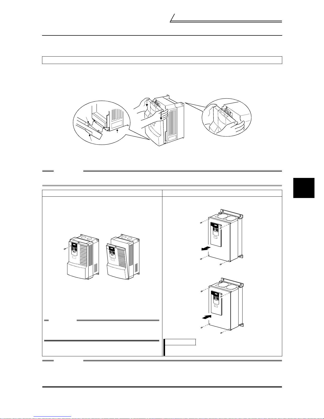
1.2 Structure
1.2.1 Removal and reinstallation of the front cover
FR-V520-1.5K to 7.5K, FR-V540-1.5K to 5.5K
Removal
!
1) Hold both sides of the front cover top and push the front cover down.
2) Hold down the front cover and pull it toward you to remove.
(The front cover may be removed with the PU (FR-DU04
j
Catch
Inverter
Front cove r
! Reinstallation
1) Insert the catches at the bottom of the front cover into the sockets of the inverter.
2) Using the catches as supports, securely press the front cover against the inverter.
CAUTION
When the operation panel is fitted to the removed front cover, reinstall the front cover after removing the
operation panel.
FR-V520-11K, 15K, FR-V540-7.5K to 18.5K FR-V520-18.5K to 55K, FR-V540-22K to 55K
•••• Removal
1) Remove the installation screw at the top of the front cover.
2) Hold both ends of the front cover top.
3) Pull the front cover toward you to remove.
(The front cover may be r em oved with the operation panel
attached.)
/FR-PU04V) on.)
-1
•••• Removal
1) Remove the installation screws at the top of the front cover.
1
OUTLINE
•••• Reinstallation
1) Insert the catches at the front cover bottom into the sockets
of the inverter.
2) Using the catches as supports, securely press the front
cover against the inverter.
3) Fix the front cover with the top screw.
CAUTION
When the operation panel is fitted to the
removed front cover, reinstall the front cover
after removing the operation panel.
CAUTION
1. Fully make sure that the front cover has been reinstalled securely.
2. The same serial number is printed on the capacity plate of the front cover and the rating plate of the
inverter. Before reinstalling the front cover, check the serial numbers to ensure that the cover
removed is reinstalled to the inverter from where it was removed.
•••• Reinstallation
1) Fix the front cover with the installation screws.
REMARKS
The 45K and 55K have two front covers, which are fixed with
eight screws.
4

Structure
1.2.2 Removal and reinstallation of the operation panel
To ensure safety, remove and reinstall the operation panel after powering off.
Removal
!
Hold down the top button of the operation panel and pull the operation panel toward you to remove.
Removal
Reinstallation
When reinstalling the operation panel, insert it straight and reinstall it securely.
! Reinstallation using the connection cable
1) Remove the operation panel.
2) Disconnect the modular jack type relay connector. (Place the disconnected modular jack type relay
connector in the modular jack type relay connector compartment.)
Modular jack type
relay connector
Modular jack type
relay connector compartment
3) Securely plug one end of the connection cable into the PU connector of the inverter and the other end into
the operation panel. (Refer to page 18 for the connection cable.)
CAUTION
Install the operation panel only when the front cover is on the inverter.
5
2 INSTALLATION AND WIRING
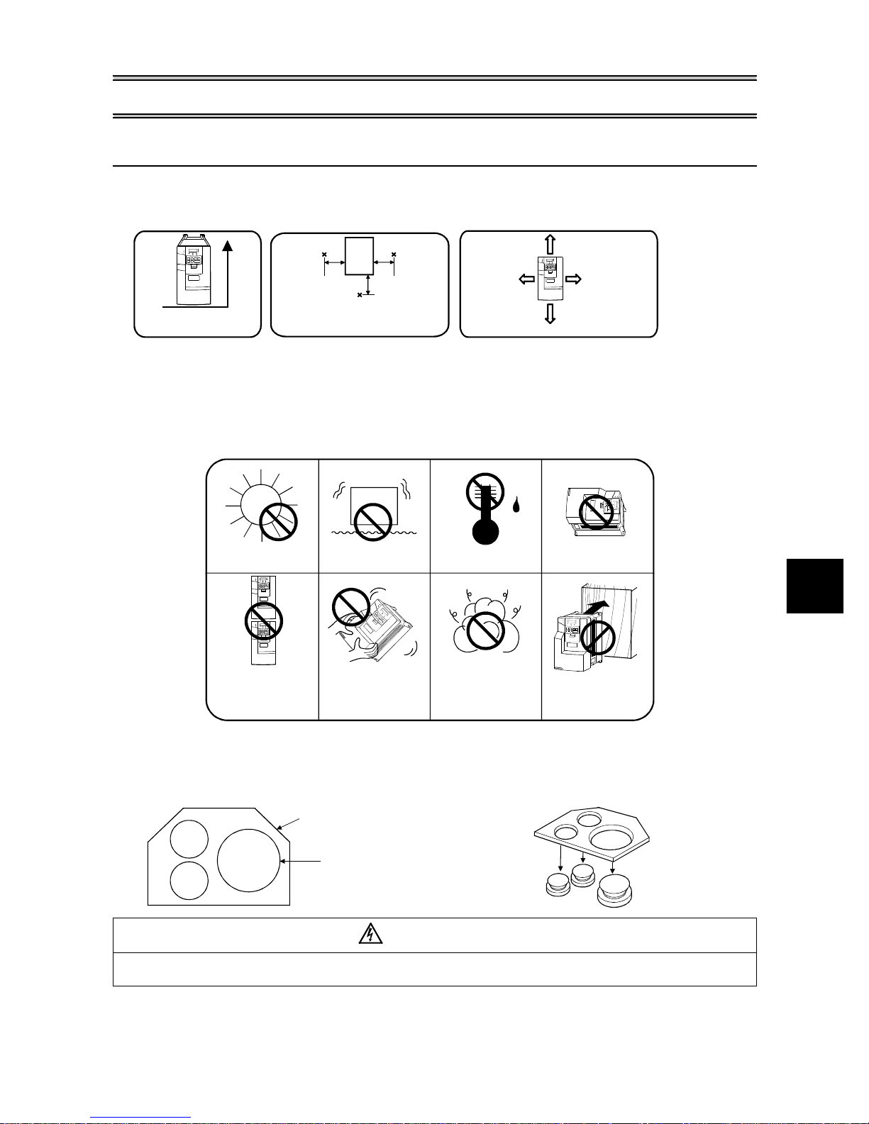
2.1 Installation of the inverter
Install the inverter under the following conditions.
!
Installation of the inverter
Vertical mounting
Vertical
The inverter consists of precision mechanical and electronic parts. Never install or handle it in any of the following
!
Ambient temperature and humidity
Measurement
position
Inverter
5cm
Measurement
position
Temperature: -10°C to 50°C
Humidity: 90%RH maximum.
Leave enough clearances and take
cooling measures.
5cm
5cm
These clearances are also necessary for
changing the cooling fan.
*1cm or more fo r 2.2K or less.
Enough clearances
5cm or
*
more
10cm
or more
10cm
or more
5cm or
more
*
conditions as doing so could cause an operation fault or failure.
.
Direct sunlight
Vibration
2
(5.9m/s or more)
.
High temperature,
high humidit y
Horizontal placement
.
2
Vertical mounting
When installing two or
more inverters, install
them in parallel .
Wiring cover and handling (15K or less for the 200V class, 18.5K or less for the 400V class)
!
Transportation by
holding front cover.
1) When cable conduits are not connected
Cut the protective bushes of the wiring cover with
nippers or a cutter before running the cables.
Oil mist, flammable gas,
corrosive gas, fluff,
dust etc.
Mounting on
combustible material
2) When cable conduits are connected
Remove the corresponding protective bushes and
connect the cable conduits.
Wiring cover
Protective bush
WARNING
Do not remove the protective bushes when cable conduits are not connected. Otherwise, the cable
sheathes may be scratched by the wiring cover edges, resulting in a short circuit or earth (ground) fault.
INSTALLATION AND WIRING
6
Connection diagram, PLG cable, PU
connector
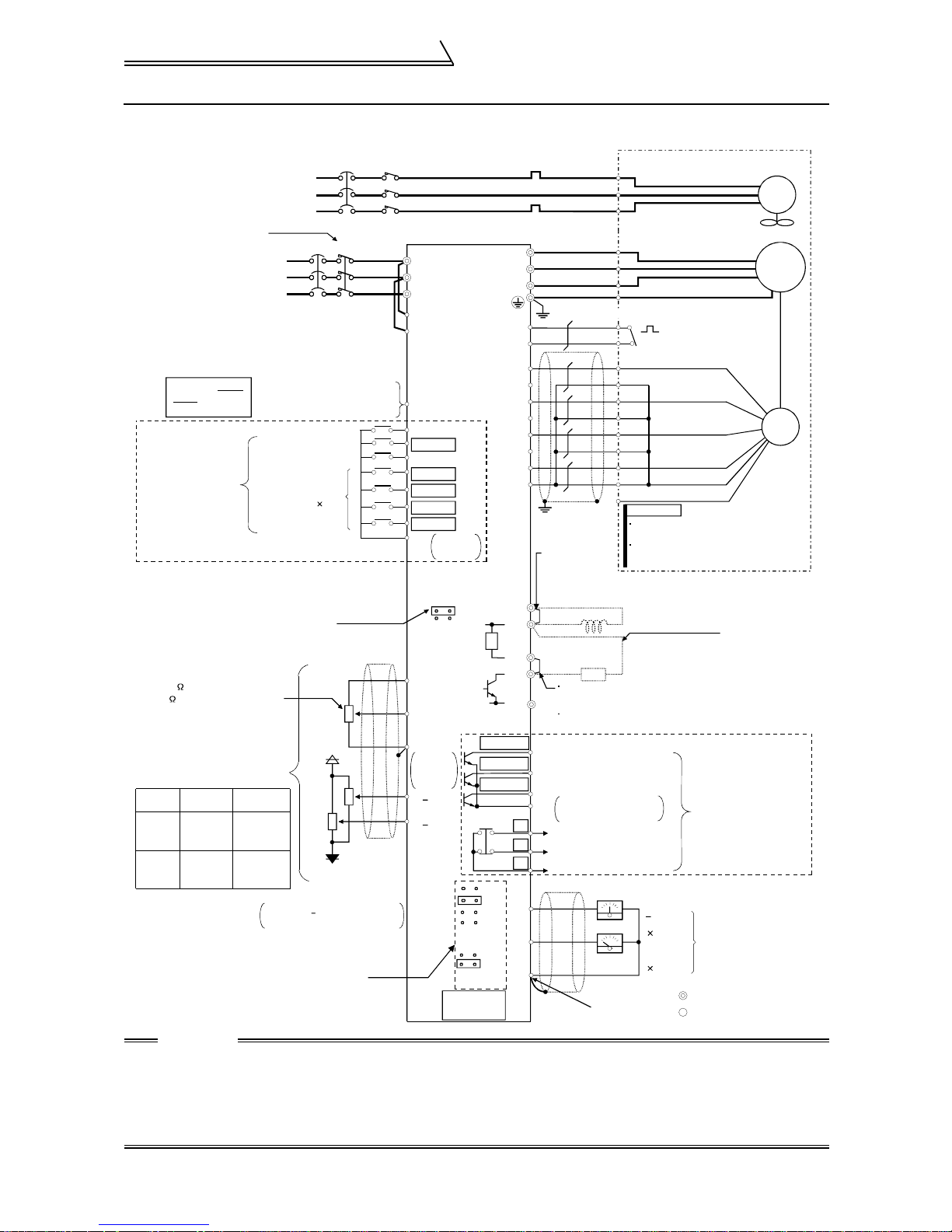
2.2 Connection diagram, PLG cable, PU connector
2.2.1 Connection diagram
NFB MC
Digital input
signal 4
+10V
-10V
External
power supply
+
NFB MC
R
S
T
3
2
1
Vector inverter
(FR-V500)
R
S
T
R1
S1
PC
STF
STR
RES
DI1(RL)
DI2(RM)
DI3(RH)
DI4(RT)
Contact
SD
input
common
SINK
SOURCE
(+10V)
10E
(0 to +10V)
2
5
Analog
input
common
+
1( 10V)
+
3( 10V)
DO1
DO2
DO3
5V
12V
24V
EXT
Differential
Complimentary
PU
connector
R
OCR
U
V
W
Earthing (Grounding)
(class D earthing (grounding))
OH
SD
PA
PAR
PB
PBR
PZ
PZR
PG
SD
Jumper
(When using the
FR-BEL, remove
this jumper.)
P1
P
PX
PR
N
(RUN)
Any of three different
(SU)
signals can be selected
using the parameter.
(IPF)
(Open collector output)
SE
A
B
C
DA1
DA2
5
(Analog output common)
A
B
C
U
V
W
E
G1
G2
A
B
C
D
F
G
S
R
N
R
Jumper (Remove this jumper
when using the FR-ABR.)
Terminal PX is provided for
the 5.5K or less.
Open collector output
common
Alarm output
(Contact output)
Meter
(+)
Verify the power specification
of the motor cooling when
performing wiring.
Refer to page 99
Avoid frequent ON-OFF.
Repeated inrush currents at
power-on will shorten the
converter life.
(Switching life is 100,000)
Take care not to
short terminals
PC-SD.
Terminals DI1 to
DI4 and STR vary
in function with
the input terminal
function selection
(Pr. 180 to Pr. 183,
Pr. 187) settings.
Control input signals (no voltage input allowed)
You can select between sink and source
Refer to page 16 for details.
Speed setting potentiometer
1/2W 1k
2W 1k is recommended for use
when speed setting is changed
frequently.
Terminal
10E, 2, 5
3
3-phase AC
power supply
External transistor common
24VDC power supply
Contact input common (source)
Forward rotation start
Reverse rotation start
Reset
Analog command
input
Speed
Control
Main
speed
command
Torque
restriction
command
Torque
Control
Speed
restriction
command
Torque
command
Prepare a 10V external power
supply for terminals 1, 3.
Change the jumper connector and
Change the jumper connector and
parameter settings according to
parameter settings according to
the PLG specifications.
the PLG specifications.
Refer to page 12 for details.
(Dedicated Motor: SF-V5R)
Match phase sequence.
(Fan should have intake rotation.)
FAN
Match phase sequence.
When using the motor
not equipped with a
thermal protector,
Thermal
set Pr. 9 and Pr. 876
protector
= "0"
PLG
REMARKS
When the motor used is not the vector
inverter motor, the pin numbers are different.
The N pin of the PLG designed for vector
inverter motor is case-earthed.
FR-BEL power factor
improving DC reactor
(option)
FR-ABR high-duty
brake resistor
(option)
+
10V
12 bits
(-)
1ch
0 to 10V
12 bits
1ch
Across terminals P
and PR, connect only
the optional,
recommended brake
resistor. In addition,
never short these
terminals.
Terminal PR is
provided for the 15K
or less.
Terminals DO1 to DO3
and ABC vary in function
with the output terminal
function selection
(Pr. 190 to Pr. 192,
Pr. 195) settings.
load impedance of 10kW or more
Monitor output
Main circuit terminal
Control circuit terminal
IM
CAUTION
• To prevent a malfunction caused by noise, separate the signal cables more than 10cm from the power
cables.
• During wiring, do not leave wire off-cuts in the inverter.
Wire off-cuts will cause an alarm, failure or malfunction. Always keep the inverter clean. When drilling
mounting holes in a control box etc., take care not to allow chips and other foreign matter to enter the
inverter.
7

Connection diagram, PLG cable, PU
2.2.2 Main circuit
(1) Specification of main circuit terminal
Terminal Symbol Terminal Name Description
R, S, T AC power input
U, V, W Inverter output Connect a motor.
R1, S1
P, PR
P, N
P, P1
PR, PX
Power supply for
control circuit
Brake resistor
connection
Brake unit
connection
Power factor
improving DC
reactor connection
Built-in brake circuit
connection
Earth (Ground) For earthing (grounding) the inver t er chassis. Must be earthed (grounded).
Connect to the commercial power supply.
Keep these terminals open when using the high power factor converter (FRHC) or power regenerati on common converter (FR-CV).
Connected to the AC power supply terminals R and S. To retain the alarm
display and alarm output or when using the high power factor converter (FR HC) or power regeneration common converter (FR-CV), remove the jumpers
from terminals R-R1 and S-S1 and apply external power to these terminals.
Do not turn off the power supply for control circuit (R1, S1) with the main
circuit power (R, S, T) on. Doing so may damage the inverter. The circuit
should be configured so that the main circuit power (R, S, T) is also turned off
when the power supply for control circuit (R1, S1) is off.
15K or less : 60VA, 18.5K to 55K : 80VA
Disconnect the jumper from term inals PR-PX (5.5K or less) and connect the
optional brake resistor (FR- ABR) across terminals P-PR.
For the 15K or less, connect ing t he r esistor further provides regenerative
braking power.
Connect the optional FR-BU brake unit, BU type brake unit, power
regeneration commo n converter (FR-CV) or high power factor con ver ter (FRHC).
Disconnect the jumper from te rmi nals P-P1 and connect the optional power
factor improving reactor (F R -BEL).
When the jumper is connected across terminals PX-PR (factory setting), the
built-in brake circuit is valid. (Provided for the 5.5K or less.)
connector
CAUTION
• The inverter will be damaged if power is applied to the inverter output terminals (U, V, W). Never perform such wiring.
• When connecting the dedicated brake resistor (FR-ABR), remove jumpers across terminals PR-PX
(5.5K or less). Set "1" in Pr. 30 "regenerative function selection". Refer to the Instruction Manual
(detailed) for details.
• When connecting the brake unit (FR-BU, BU), remove jumpers across terminals PR-PX (5.5K or less).
Refer to the Instruction Manual (detailed) for details.
2
INSTALLATION AND WIRING
8
Connection diagram, PLG cable, PU
connector
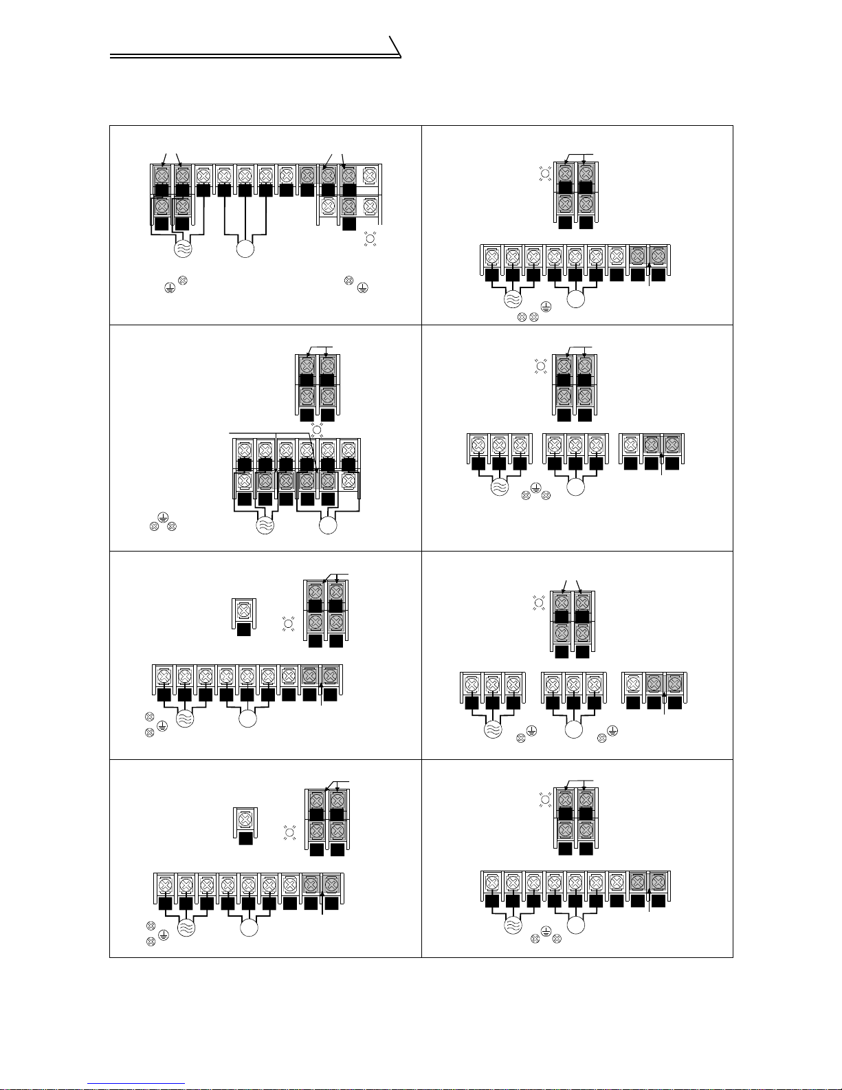
(2) Terminal arrangement of the main circuit terminal
In the main circuit of the inverter, the terminals are arranged as shown below:
200V class
FR-V520-1.5K, 2.2K FR-V520-18.5K
Jumpers
RTS
Screw size (M4)
UVW
Jumpers
Charge lamp
PR
P1
P
N
R1 S1
Jumpers
Screw size (M4)
S1R1
Power supply
Screw size (M4)
FR-V520-3.7K, 5.5K, 7.5K
Screw size (M4)
Jumper
Screw size (M5)
Screw size (M5)
IM
Motor
ST
R
N
P1 PR PX
R1 S1
P
PX
Charge lamp
Jumpers
RS
Charge lamp
UVW
IM
FR-V520-22K
Charge lamp
R
S
7.5K is not provided with the PX terminal and PX- PR jum per.
FR-V520-11K FR-V520-30K, 37K
Screw size (M5)
Screw size (M6)
Screw size (M4)
PR
Charge
lamp
R1 S1
Jumpers
Charge lam p
RS
RNRS
Screw size (M8)
ST P
T
U V W
IM
Screw size (M6)
R1 S1
R
S
V
IM
Screw size (M6)
Jumpers
R1 S1
RS
P1
Jumper
Jumpers
Screw size (M4)
Screw size (M8)
W
N
Screw size (M4)
Screw size (M10)
P1U
Jumper
P
RS
Screw size (M6)
T
U V W
IM
FR-V520-15K FR-V520-45K, 55K
Screw size (M4)
Screw size (M5)
PR
Charge
Screw size (M8)
RS
T
Screw size (M6)
U V W
lamp
IM
N
N
P1
Jumper
R1 S1
RS
P1
Jumper
P
P
Jumpers
R
ST
Screw size (M8)
Charge lamp
ST P
V W
U
IM
R1 S1
RNRS
U V W
IM
Screw size (M8)
N
Jumpers
Screw size (M4)
Screw size (M12)
P
Jumper
P1
Jumper
P1
9
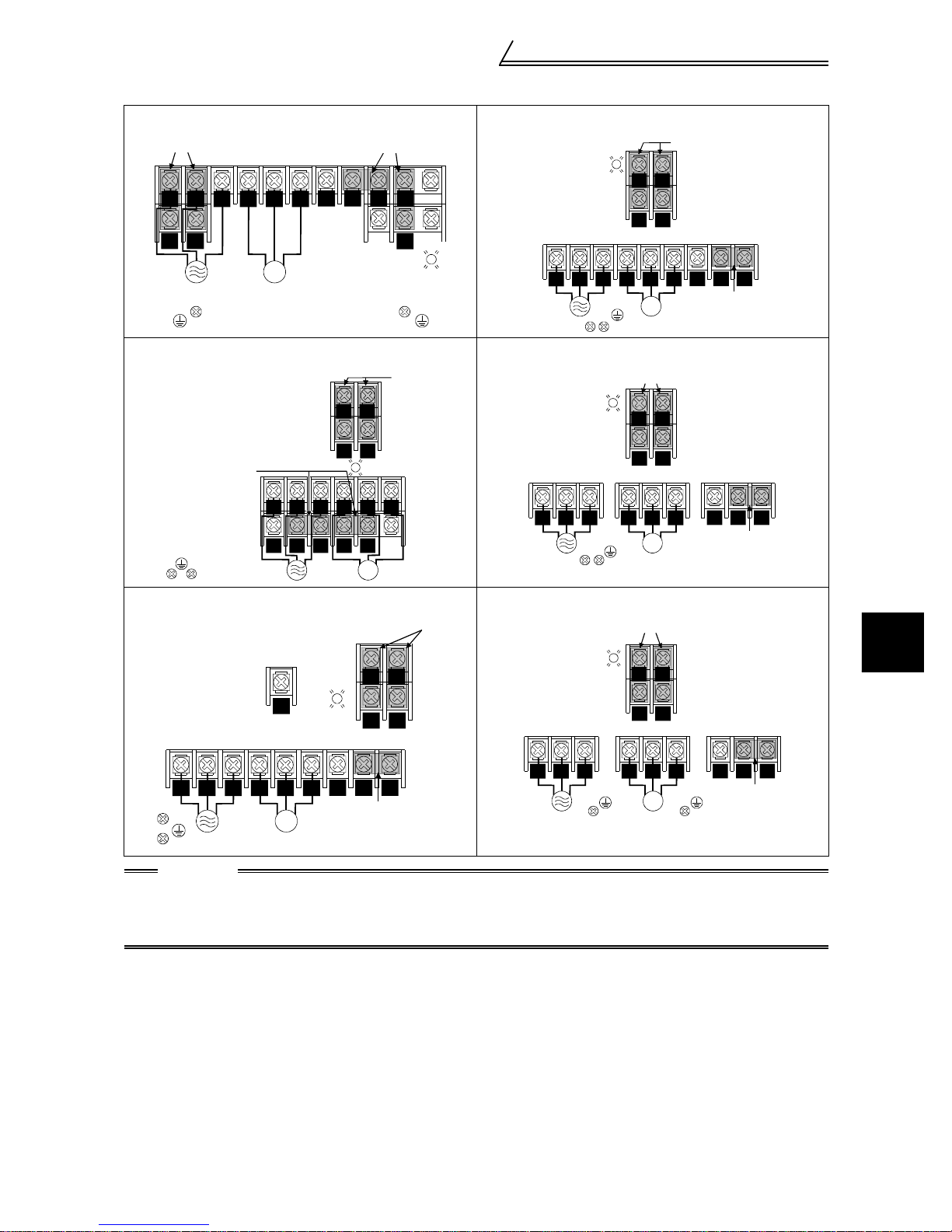
Connection diagram, PLG cable, PU
400V class
FR-V540-1.5K, 2.2K FR-V540-18.5K
connector
Jumpers
RS
Power supply Motor
Screw size (M4)
T
S1R1
Screw size (M4)
UVW
N
IM
Jumpers
P1
P
Charge lamp
PR
PX
Charge lamp
R1 S1
ST P
U V W
FR-V540-3.7K, 5.5K FR-V540-22K
Jumper
Screw size (M4)
Screw size (M4)
Screw size (M4)
RST
NP
P1 PR PX
R1 S1
S
R
Charge lamp
UVW
IM
Jumpers
Charge lamp
RST N P
Jumpers
R1 S1
U V W
Screw size (M6)
FR-V540-7.5K, 11K, 15K FR-V540-30K, 37K, 45K, 55K
Screw size (M5)
Screw size (M6)
Screw size (M4)
PR
Charge
lamp
Jumpers
Charge lamp
R1 S1
RS
Jumpers
R1 S1
Jumpers
Screw size (M4)
RNRS
Screw size (M6)
IM
Screw size (M6)
Screw size (M4)
RS
Screw size (M6)
IM
Screw size (M4)
RS
P1
Jumper
P1
Jumper
2
Screw size (M8)
RST
IM
Screw size (M6)
CAUTION
• Always connect the power supply cables to R, S, T. If they are connected to U, V, W , the inverter will be
damaged. (Phase sequence needs not to be matched.)
• Connect the motor to U, V, W. At this time, turning on the fo rward rotation switch (sig nal) rotates the
motor in the counterclockwise direction when viewed from the motor shaft.
RST
P1U V W
N
P
Jumper
U V W
IM
Screw size (M8)
P1
NP
Jumper
INSTALLATION AND WIRING
10
Connection diagram, PLG cable, PU
connector
(3) Cables and wiring length
Select the recommended cable size to ensure that a voltage drop will be 2% max.
If the wiring distance between the inverter and motor is long, the motor torque will decrease due to the voltage drop of the
main circuit cable especially at high-frequency output. The PLG signal will also be affected by the voltage drop.
The following table indicates a selection example for the wiring length of 20m.
200V class (When input power supply is 220V)
Applicable Inverter
Type
FR-V520-1.5K, 2.2K M4 1.5 2 2
FR-V520-3.7K M5 2.5 3.5 3.5
FR-V520-5.5K M5 2.5 5.5 5.5
FR-V520-7.5K M5 2.5 14 8
FR-V520-11K M6 4.4 14 14
FR-V520-15K M8 7.8 22 22
FR-V520-18.5K, 22K M8 7.8 38 38
FR-V520-30K M10 14.7 60 60
FR-V520-37K M10 14.7 100 100
FR-V520-45K M12 24.5 100 100
FR-V520-55K M12 24.5 150 150
Terminal
Screw Size
Tightening
Torque
N·m
400V class (When input power supply is 440V)
Applicable Inverter
Type
FR-V540-1.5K, 2.2K M4 1.5 2 2
FR-V540-3.7K M4 1.5 2 2
FR-V540-5.5K M4 1.5 3.5 2
FR-V540-7.5K M6 4.4 3.5 3.5
FR-V540-11K M6 4.4 5.5 5.5
FR-V540-15K M6 4.4 14 8
FR-V540-18.5K M6 4.4 14 8
FR-V540-22K M6 4.4 22 14
FR-V540-30K M8 7.8 22 22
FR-V540-37K M8 7.8 38 22
FR-V540-45K M8 7.8 38 38
FR-V540-55K M8 7.8 60 60
Terminal
Screw Size
The line voltage drop can be calculated by the following expression:
Tightening
Torque
N·m
HIV Cables
mm
R, S, T
HIV Cables
mm
R, S, T
2
U, V, W
2
U, V, W
Line voltage drop [V]
3 × cable resistance[m /m]× wiring distance[m] × current[A]
=
1000
Use a larger diameter cable when the wiring distance is long or when it is desired to decrease the voltage drop
(torque reduction) in the low speed range.
CAUTION
• Tighten the terminal screw to the specified torque.
A screw that has been tighten too loosely can cause a short circuit or malfunction.
A screw that has been tighten too tightl y can cau se a shor t circuit or malfun ction due to the unit br eakage .
• The crimping terminals recommended for use to wire the po wer supply and mo tor are those pr ovided
with insulation sleeves.
(4) Wiring length
The wiring length should be 100m maximum. (during vector control)
!
CAUTION
• Especially for long-distance wiring, the inverter may be affected by a charging current caused by the
stray capacitances of the wiring, leading to a malfunction of the overcurrent protective function or a
malfunction or fault of the equipment connected on the secondary side. If fast-responce current
restriction malfunctions when fast-responce current restrict ion function is made valid, disable fastresponce current restriction. (Refer to Pr.156 "stall prevention operation selection". )
(5) Cable gause for the control circuit power
• Cable gause: 0.75mm2 to 2mm
• Tightening torque: 1.5N•m
2
11
Connection diagram, PLG cable, PU
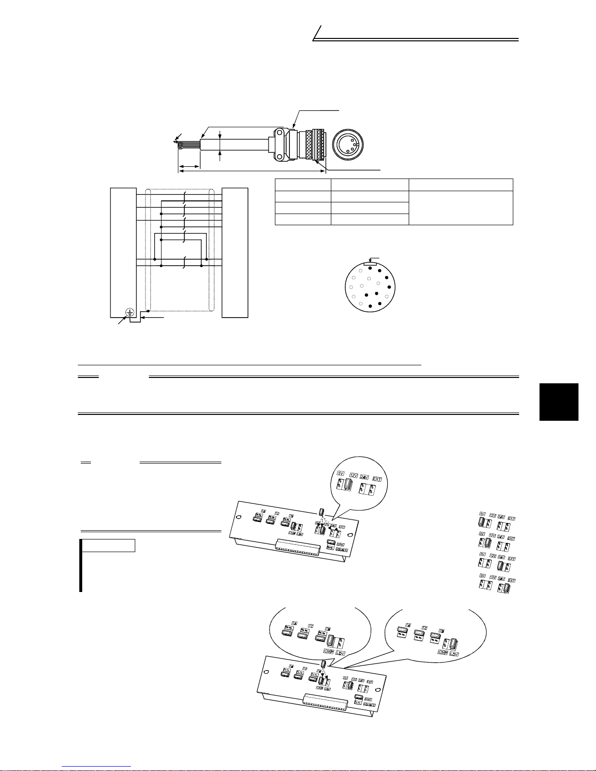
2.2.3 PLG connection cable (FR-V5CBL)
When using a dedicated motor (SF-V5R series), use a PLG cable (FR-V5CBL) for connection.
connector
Inverter side
60
2
F-DPEVSB 12P
11
A
B
C
D
F
G
S
R
Earth (Ground) wire
FR-V500 PLG (SF-V5R)
PA
PAR
PB
PBR
PZ
PZR
PG
SD
2mm
Inverter earth ( ground) terminal
PLG side
×
L
connector
0.2mm
MS3057-12A
2
MS3106B20-29S
Type Length L (m) Remarks
FR-V5CBL5 5
FR-V5CBL30 30
Contact us separately for other lengths.
A
M
N
L
T
K
S
J
H
MS3106B20-29S
(As viewed from wiring side)
Standard productFR-V5CBL15 15
Positioning keyway
B
C
D
P
E
R
F
G
(Unit: mm )
2.2.4 Setting the PLG
When a dedicated PLG cable (FR-V5CBL) is used, a setting change may not be required.
CAUTION
Make setting correctly.
Fitting the jumper connector to the position exceedin g the power specification results in a PLG failure.
Fitting the jumper connector to the position be low the power specification results in a PLG malfunction.
(1) Setting the power supply specification of the PLG and pulse output type
Switch the position of the jumper connector on the back surface of the control c ircuit terminal block according
to the PLG specification. (Refer to page 16 for removal and installation of the control circuit terminal block.)
2
CAUTION
• PLG power supply jumper
connector
The connector is fitted to 12V
at factory shipment. Switch its
position according to power
supply specification.
REMARKS
Since the specification of the PL G of
the conventional motors (SF-VR, SFJR with PLG) is 5V, fit the jumper connector to 5V.
PLG output circuit jumper
!
connector
The connector is fitted to
complimentary at factory shipment.
Switch its position according to
output circuit.
Complimentary (CMP)
Terminating resistance
12
Power supply voltage is 5.5V
Power supply voltage is 12V
Power supply voltage is 24V
INSTALLATION AND WIRING
Power supply voltage is external
Differential line driver (LDV)
Terminating resistance
Connection diagram, PLG cable, PU
connector
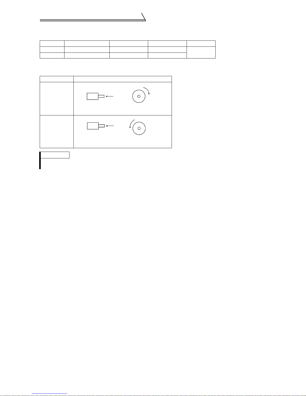
(2) Setting the number of PLG pulses and PLG rotation direction
Set the following parameters according to the PLG specification.
Parameter Name Factory Setting Setting Range Remarks
851 Number of PLG pulses 2048 0 to 4096
852 PLG rotation direction 1 0, 1
The rotation direction monitor of the parameter unit displays the rotation direction of the encoder,
!
refer to the following table.
Pr. 852 Setting Relationship between the motor and PLG
Extension
mode
CW
0
1
(factory setting)
A
PLG
Forward rotation is clockwise rotation
when viewed from A.
CCW
A
PLGAPLG
Forward rotation is counterclockwise rotation
when viewed from A.
REMARKS
• By setting "1" in Pr.160 "extended function selection", Pr. 851 and Pr. 852 are made valid.
• The number of P LG pulses should be between 1000 and 4096.
When using a conventional motor and a PLG cable (FR-VCBL/FR-JCBL), refer to the
!
Instruction Manual (detailed).
13
2.2.5 Control circuit
(1) Specifications of control circuit ter mi nals
Terminal
Type
Symbol
STF Forward rotation start
STR Reverse rotation start
DI1 to DI4
OH T hermal protector input
RES Reset
Contact input
SD
PC
10E
2 Speed setting (voltage)
3 Torqu e setting terminal
Input signals
Speed setting
1
5 Speed setting common
PA
PAR
PB
PBR
PZ
PZR
PLG signal
PG
SD
Terminal Name Description
Turn on the STF signal to start forward
rotation and turn it off to stop.
Turn on the STR signal to start reverse
rotation and turn it off to stop.
The terminal function varies with the input
terminal function selection (Pr. 187) setting.
Refer to page 61 for details.
Digital input
terminals 1 to 4
Contact input common
(sink)
24VDC power supply
and external transistor
common, contact inpu t
common (source)
Speed setting power
supply
Multi-function setting
terminal
A-phase signal input
terminal
A-phase inverted signal
input terminal
B-phase signal input
terminal
B-phase inverted signal
input terminal
Z-phase signal input
terminal
Z-phase inverted signal
input terminal
PLG power supply
terminal
(Positive side)
Power supply earth
(ground) terminal
The terminal functions vary wi th the in put terminal function selection (Pr. 180 to Pr.
183) settings. Refer to page 61 for details.
Temperature sensor terminal input for motor overheat protection.
OHT error occurs when terminals OH and SD are open.
Used to reset instantly. By setting Pr. 75 "reset selection", reset input possible or
reset input possible only during protective circuit operation can be selected. Turn on
the RES signal for more than 0. 1s, then turn it off.
Common to the contact input. Common output terminal for 24VDC 0.1A power
supply (PC terminal). Isol at ed fr om te rmi nals 5 and SE.
When connecting a transistor output (open collector output), such as a
programmable contr ol ler, connect the ex te rn al p ower supply common for transistor
output to this terminal to pr event a malfunction caused by a sneak current .
PC-SD can be used as a 24VDC, 0.1A power supply. Note that this connection does
not prevent a sneak curr ent.
When source logic has be en selected, this terminal serves as a contact input
common.
10VDC, permissible lo ad current 10mA
By entering 0 to 10VDC, the m axi m um output speed is reached at 10V and I/O are
proportional. Acts as a spe ed command terminal for speed control or as a speed
restriction for torque control. Input resistance 10kΩ, maximum permissible vol t age
20V.
Acts as a torque setting signal fo r tor que control or a torque restriction signal for
speed control and posi tion control.
Acts as an input terminal when torque bias function by external analog is selected.
0 to ±10VDC input, input resistance 10kΩ, maximum permissibl e voltage ±20VDC
Since this is a multi-function sel ec tion terminal, its function varies with the Pr. 868
"No. 1 terminal function assignment" setting. The function of this terminal is factoryset to adding auxiliary of speed setting terminal of terminal 2.
Refer to Pr. 868 "No. 1 terminal function assignm ent " i n th e Inst r uct i on M anual
(detailed).
0 to ±10VDC input, input resistance 10kΩ, maximum permissibl e voltage ±20V
Speed setting signal (term in al 2, 1 or 3) co mmon terminal.
Isolated from terminals SD and SE. D o no t e arth(ground).
A-, B- and Z-phase signals are inp ut from th e PLG.
The PLG jumper connec tor is set to complimentary when shipped from the f ac to ry.
Thus, the PLG need not be conn ected to PAR, PB R, and PZR.
Power supply f or PLG. You can switch the power supply between 5, 12 and 24VDC.
You can also switch to external power supply.
The PLG jumper connecto r is set to 12VDC when shipped from the factory. (Refer
to page 12.)
Common terminal for the PLG power supply.
Isolated from terminals 5 and SE.
Do not earth (ground).
Connection diagram, PLG cable, PU
connector
When the STF and STR signals are
turned on simultaneously, the stop
command is given.
2
INSTALLATION AND WIRING
14
Connection diagram, PLG cable, PU
connector
Terminal
Type
Symbol
A, B, C Al arm out put
Contact
DO1 to
DO3
SE
Open collector
Output signals
DA1 A n al og signal output
DA2 A n al og signal output
Analog
5
– PU connector
RS-485
Communication
Terminal Name Description
1 contact output indicating that the output has been stopped by the invert er
protective function
230V A C 0.3 A, 30V DC 0. 3A. Al ar m: di scon ti nuity acro ss B -C (c onti nui ty ac ros s A-C ),
Normal: continuity across B-C (discontinuity across A-C).
The terminal function varies with the output terminal function selection (Pr. 195 )
setting.
Refer to page 61 for details.
Digital output terminals
1 to 3
Open collector output
common
Analog signal output
common
Permissible load 24VDC 0.1A
The terminal functions vary with the output terminal function selection (Pr. 190 to Pr.
192) settings. Refer to page 61 for details.
Common terminal for terminals DO1, DO2 and DO3. Isolated from terminals SD and
5.
One selected from the monitoring items,
such as the speed, is outp ut .
The output signal is proportional to the
magnitude of the corresponding monitoring
item.
Common terminal for DA1 and DA2.
Isolated from terminals SD and SE.
Do not earth(ground).
With the PU connector, communication can be m ade through RS -485.
• Conforming standard : EIA Standard RS-485
• Transmission format : Multidrop link system
• Communication speed: Maximum 19200bps
• Overall length : 500m
Factory setting of output item :
*
Speed monitoring, output si gnal 0 to
±10VDC, permissible load current 1mA
Factory setting of output item :
Torq ue monitoring, output signal 0 to
10VDC, permissible load current 1mA
* Not output during inverter reset.
REMARKS
For the input terminal function switchover timing, refer to page 42.
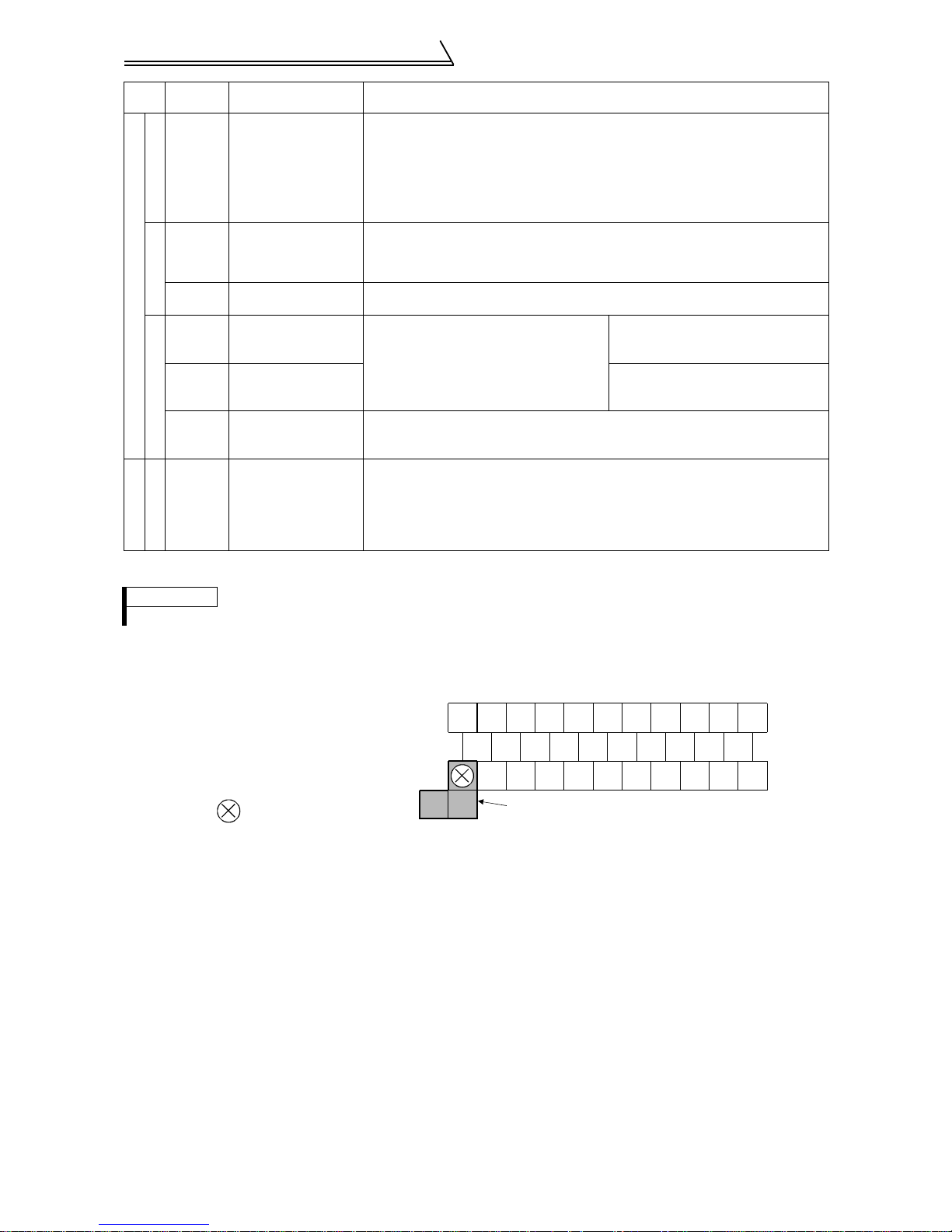
(2) Control circuit terminal layout
Terminal screw size: M3.5
Tightening torque : 1.2N·m
When connecting three or more control cables
to the No. 5 terminal, con nect the accessory
No. 5 terminal dedicated L- shaped jumper to
the No. 5 terminal.
In this case no cable should be connected to
the screw in the part.
A
BDO1DO2DI4
C
10E
2 DA1 SE PZ PZR PG RES
3 1 PA PAR PB PBR SD OH
5
5
DO3
DA2
Jumper
DI3 DI2 DI1
STR
STF
PC
SD
(3) Wiring instructions
1) Terminals 5, SD and SE are common to the I/O signals and isolated from each other. These common terminals
must not be connected to each other nor earthed (grounded).
2) Use shielded or twisted cables for connection to the control circuit terminals and run them away from the main
and power circuits (including the 200V relay sequence circuit).
3) Since the control circuit input signals are micro currents, use two parallel micro signal contacts or a twin contact to prevent a contact fault.
4) It is recommended to use the cables of 0.75mm
cable gauge used is 1.25mm
2
or more, the front cover may be lifted when there are many cables running or the
cables are run improperly, resulting in an operation panel or parameter unit contact fault.
5) The maximum wiring length should be 30m.
2
gauge for connection to the control circuit terminals. If the
15
Connection diagram, PLG cable, PU
connector
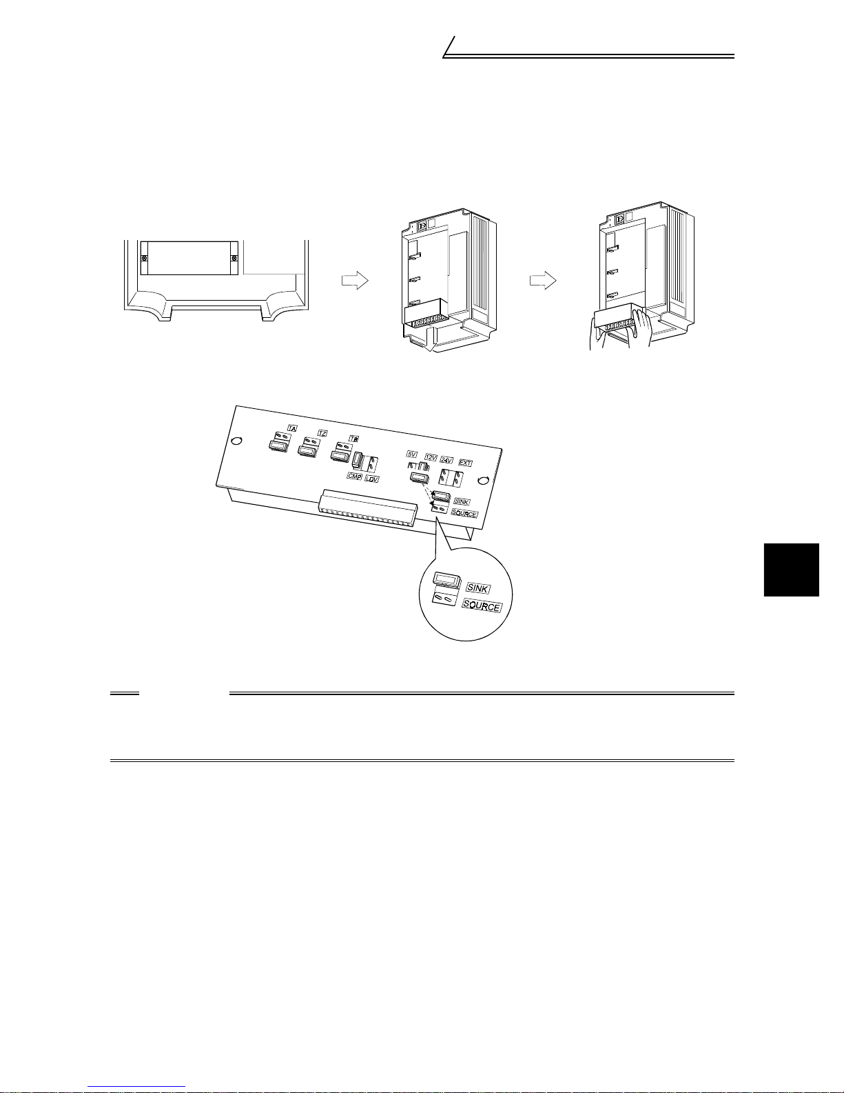
(4) Changing the control logic
The input signals are factory set to sink logic (SINK).
To change the control logic, the jumper connector on the back of the control circuit terminal block must be moved to
the other position.
(The output signals may be used in either the sink or source logic independently of the jumper connector position.)
1) Loosen the two mounting screws in both ends of the control circuit terminal block. (The screws cannot be
removed.) With both hands, pull down the terminal block from the back of the control circuit terminals.
2) Remove the jumper connector from the sink logic (SINK) position on the back surface of the control circuit terminal block and fit it to the source logic (SOURCE) position.
3) Using care not to bend the pins of the inverter's control circuit connector, reinstall the control circuit terminal
block and fix it with the mounting screws.
CAUTION
1. Make sure that the control circuit connector is fitted correctly.
2. While power is on, never disconnect the control circuit terminal block.
3. The sink-source logic change-over jumper connector must be fitted in o nly on e of those p ositio ns. If
it is fitted in both positions at the same time, the inverte r may be damaged.
2
INSTALLATION AND WIRING
16
Connection diagram, PLG cable, PU
connector
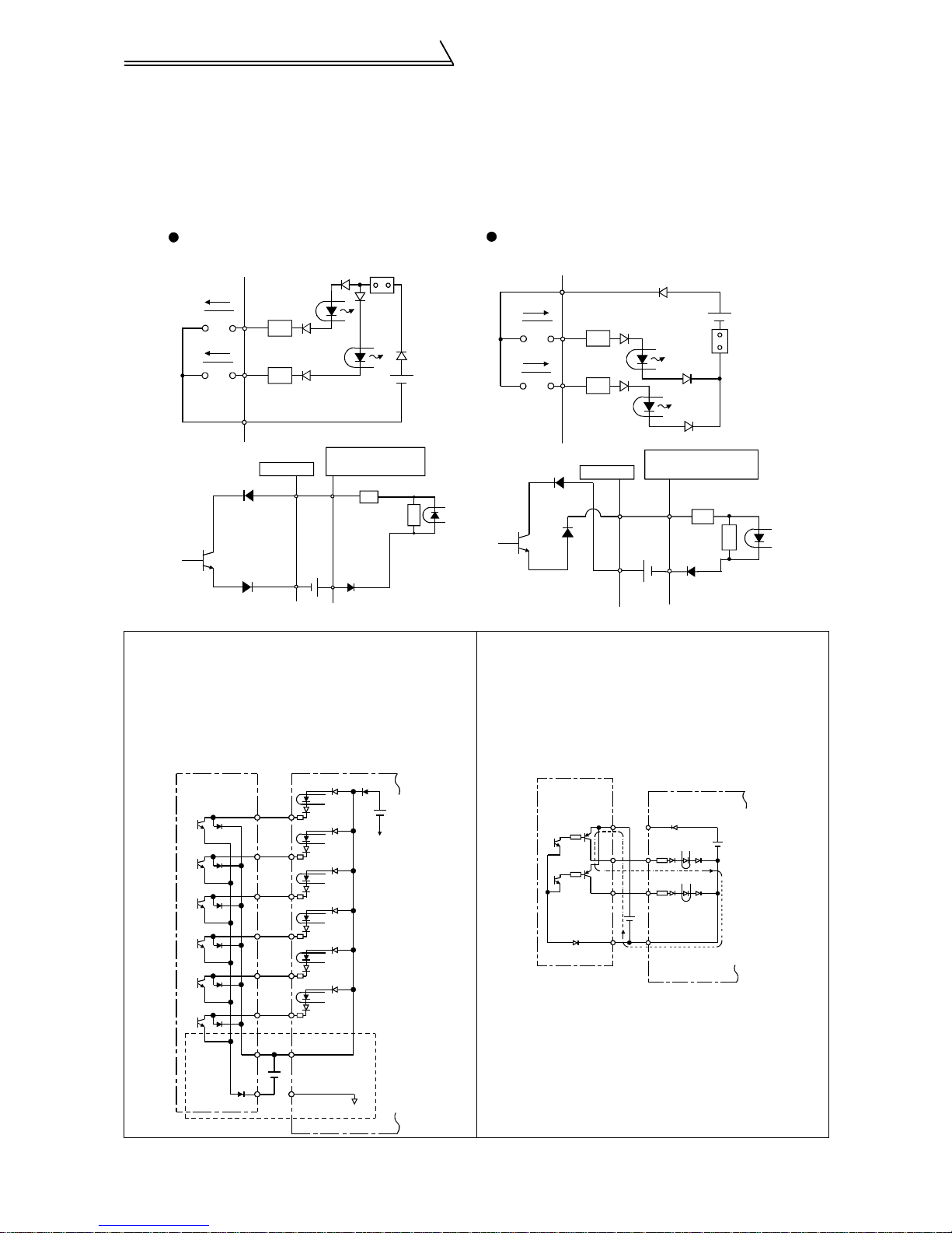
4) Sink logic type and source logic type
• The sink logic type is a logic where a signal turns on when a current flows out of the corresponding signal
input terminal.
Terminal SD is common to the contact input signals. Termi nal SE is common to the open collector output signals.
• The source logic type is a logic where a signal turns on when a current flows into the corresponding signal
input terminal.Terminal PC is common to the contact input signals. Terminal SE is common to the open collector output signals.
Current flow concerning the RUN signal
when sink logic is selected
Sink logic
Current
STF
R
STR
R
SD
Inverter
RUN
SE
When using an external power supply for transistor output
!
24VDC
Sink connector
DC input (sink type)
<Example : AX40>
1
R
9
R
• Sink logic type
Using terminal PC as a common terminal prevents a
malfunction caused by undesirable current. (Do not
connect terminal SD of the inverter with terminal 0V
of the external power supply. When using terminals
PC-SD as a 24VDC power supply, do not install a
power supply in parallel in the outside of the inverter.
Doing so may cause a malfunction due to undesirable current.)
STF
STR
RH
RM
RL
RES
PC
SD
Inverter
24VDC
(SD)
AY40 type
transistor
output module
1
2
3
4
5
6
9
10
24VDC
Current flow concerning the RUN signal
when source logic is selected
Source logic
PC
Current
STF
STR
R
R
Inverter
RUN
SE
DC input (source type)
<Example : AX80>
1
9
24VDC
Source
connector
R
R
• Source logic type
Use terminal SD as a common to prevent a malfunction caused by undesirable current.
AY80 type
transistor
output module
9
1
2
10
PC
STF
STR
24VDC
SD
Inverter
24VDC
(SD)
17

Connection diagram, PLG cable, PU
connector
2.2.6 Connection to the PU connector
(1) When connecting the operation panel or parameter unit using a connection cable
<Recommended connection cable>
• Parameter unit connection cable (FR-CB2) (option) or the following connector and cable available on the market
• Connector : RJ45 connector
Example: 5-554720-3 of Tyco Electronics Corporation
• Cable : Cable conforming to EIA568 (e.g. 10BASE-T cable)
Example:
• Maximum wiring length : 20m
SG LPE V 0.5mm x 4P (twisted pair cable, 4 pairs) of M itsubishi Cable Industries, LTD.
(2) For computer link communication
Using the PU connector, you can perform communication operation from a personal computer etc. By connecting
the PU connector to computers such as a personal computer and FA unit with a communication cable, you can run/
monitor the inverter and read/write parameter values using a user program.
Refer to the Instruction Manual (detailed) for details.
• Conforming Standard : EIA Standard RS-485
• Transmission form : Multidrop link system
• Communication speed : Maximum 19200bps
• Overall length : 500m
CAUTION
Do not connect the PU connector to the computer's LAN b oard, FAX modem socket or telephone connector. Doing so may damage the inverter due to electrical specification differences.
2.2.7 Notes on earthing (grounding)
Leakage currents flow in the inverter. To prevent an electric shock, the inverter and motor must be earthed
!
(grounded).
Use the dedicated earth (ground) terminal to earth (ground) the inverter. (Do not use the screw in the case, chassis,
etc.)
Use the largest possible gauge for the earth (ground) cable. The gauge should be equal to or larger than those
!
indicated in the following table. The earthing (grounding) point should be as near as possible to the inverter to
minimize the earth (ground) cable length.
Motor Capacity
2.2kW or less 2 2
3.7kW 3.5 2
5.5kW, 7.5kW 5.5 3.5
11kW, 1 5kW 14 8
18.5kW to 37kW 22 14
45kW, 55kW 38 22
Earth (Ground) the motor on the inverter side using one wire of the 4-core cable.
!
Earth (Ground) Cable Gauge
200V class 400V class
2
INSTALLATION AND WIRING
18

Setting the motor
2.3 Setting the m otor
This inverter is factory-set to run the dedicated motor (SF-V5R (1500r/min series) with PLG)
(It is not necessary to reset the inverter if you use the dedicated motor (SF-V5R (1500r/min series) with PLG) (only
when inverter capacity = motor capacity).)
POINT
The parameter below is extended mode parameter. Set "1" in Pr. 160 "extended function selection".
2.3.1 Dedicated motor (SF-V5R (1500r/min series))
1Check that the Pr.71 "applied motor" (extended mode) setting is "30" (SF-V5R) (factory setting value).
2.3.2 Motor one rank lower than the dedicated motor (SF-V5R (1500r/min series))
(1) Set the parameter shown below.
Parameter Name Factory Setting Setting Range
80 Motor capacity Inverter ca pacity 0.4kW to 55kW
19

Setting the motor
REMARKS
When using a conventional motor (SF-VR, SF-JR) or other motors, refer to the
Instruction Manual (detailed).
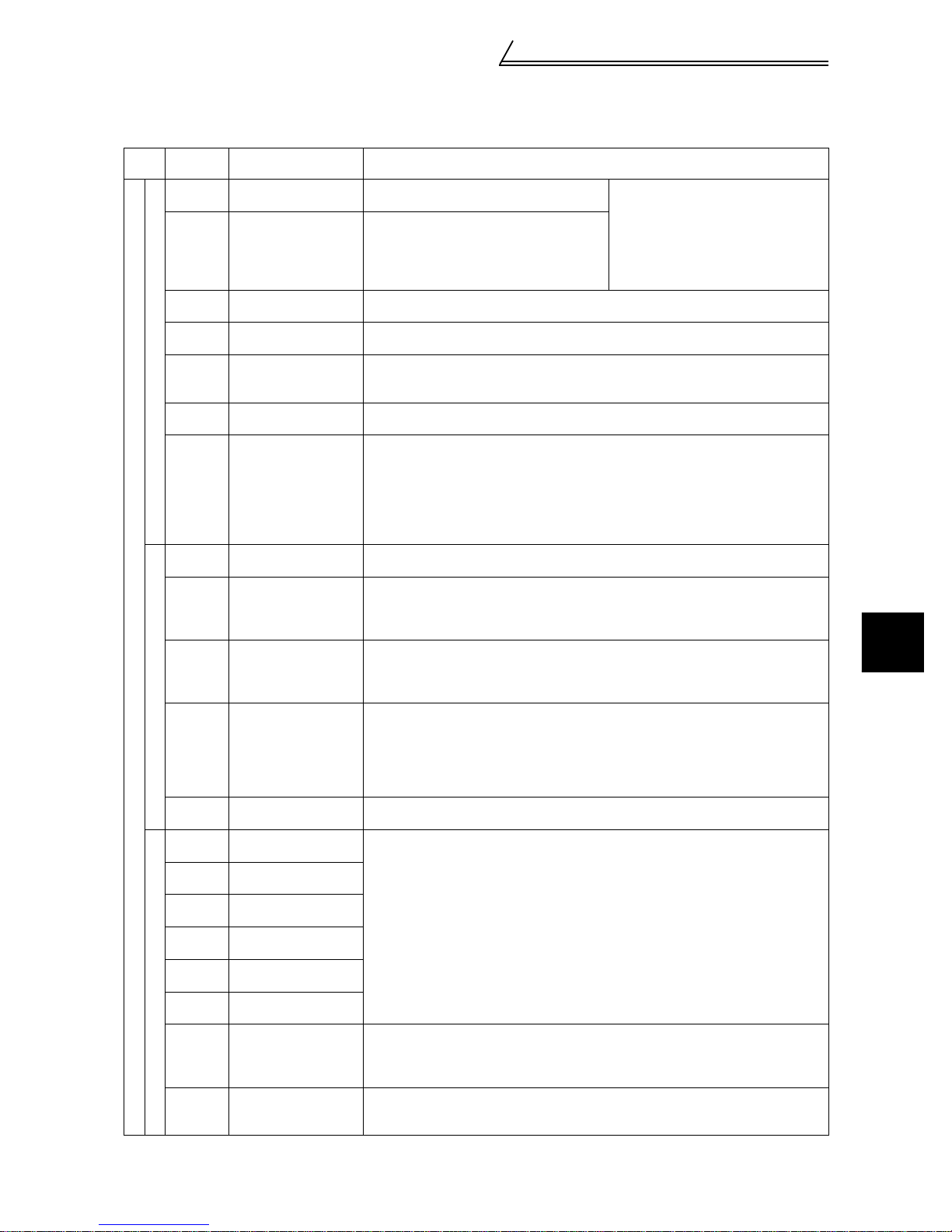
<At-a-glance guide to motor setting>
Dedicated Motor Standard Motor
No. Item
Motor
1
setting
Offline
2
tuning
Capacity
3
setting
Number
4
of PLG
pulses
PLG
5
rotation
direction
PLG
power
6
supply
specifi-
cation
PLG
7
output
type
Electronic
8
thermal
relay
Thermal
9
protector
input
Torque
10
charac-
teristic
Parameter,
Jumper Con-
necter, Ter-
minal
Pr. 71 setting
Pr. 80 setting
Pr. 851setting 2048 1000 1024 1024 1024 - - 1024 1024 -
Pr. 852 setting
PLG
power supply
jumper con-
necter on the
back of the
control termi-
nal
Pr. 9 setting
Across
OH-SD
Pr. 876 setting
Pr. 801 setting
1 :1
1 rank
lower
Power
supply
specifi-
cation
Output
circuit
Termi-
nating
resistance
Mitsubishi Mitsubishi
SF-V5R
1500r/min
Description
series
required *
INV
capacity
Motor
capacity
12V 5V 5V 5V 5V - - 5V 5V -
Complimentary
Connect to
the thermal
SF-VR
30 30 0 20 3 to 8 3 to 8 3 to 8 10 13 to 18 13 to 18
Not
1 1 1 1 1--1 1-
No Yes Yes Yes Yes - - Yes Yes -
0 0
1 1000- -00-
1 1
Not
required *
INV
capacity
Motor
capacity
Differential Differential Differential Differential - - Differential
Connect to
the thermal
SF-JR (with PLG)
(2, 4, 6P)-
2.2kW to
55kW
Not
required *
INV
capacity
Motor
capacity
Rated
inverter
current
Open Open Open - - Open Open -
0 or 1
(Selection
is
required)
(4P)-
1.5kW or
less
required *
INV
capacity
Motor
capacity
Rated
inverter
current
0 or 1
(Selection
required)
SF-HR
(with PLG)
Not
Required Required Required
capacity
capacity
(Selection
is
required)
INV
Motor
Rated
inverter
current
0 or 1
is
(with PLG)
capacity
capacity
(Selection
required)
Others
INV
Motor
0 or 1
Other
manufac-
turer
(with PLG)
INV
capacity
Motor
capacity
--
0 or 1
(Selection
is
is
required)
CAUTION
1. Set number of motor poles in Pr.81.
2. For -, make setting according to the motor used.
3. The half-tone screened cells are factory set.
4. Check the power supply specification of PLG and change a jumper connecter.
5. *:Perform offline auto tuning (mode without rotation) for the wiring length to be reflected on the control when the wiring length is long (30m or longer as reference).)
<When using other manufacturers’ motors>
offline auto tuning (rotation mode) is necessary. Perform offline auto tuning with the motor alone before
connecting a load. If higher torque accuracy is required, perform online auto tuning next.
Constant-torque Motor
(with PLG)
Mitsubishi
SF-HRCA
(4P) (with
required *
(Selection
required)
PLG)
Not
INV
capacity
Motor
capacity
Rated
inverter
current
0 or 1
is
SF-JRCA
(with
PLG)
Required Required
INV
capacity
Motor
capacity
Differen-
tial
Rated
inverter
current
0 or 1
(Selec-
tion
is
required)
Other
manufac-
turer
INV
capacity
Motor
capacity
-
-
0 or 1
(Selection
is
required)
2
INSTALLATION AND WIRING
Offline auto tuning
The inverter measures necessary motor circuit constant and stores it to improve low speed
torque.
Online auto tuning
High torque accuracy corresponding to the motor temperature variation is available.
20

Precautions for use of the vector inverter
2.4 Precautions for use of the vector inverter
The FR-V500 series is a highly reliable product, but incorrect peripheral circuit making or operation/handling
method may shorten the product life or damage the product.
Before starting operation, always recheck the following items.
(1) Use insulation-sleeved crimping terminals for the power supply and motor cables.
(2) Power must not be applied to th e output termina ls (U, V, W) of the inverter. Otherwise the inverter will be damaged.
(3) After wiring, wire off-cuts must not be left in the inverter.
Wire off-cuts can cause an alarm, fault or malfunction. Always keep the inverter clean.
When drilling mounting holes in a control box or the like, use care not to allow chips etc. to enter the inverter.
(4) Wire the cables of the recommended size to make a voltage drop 2% or less.
If the wiring distance is long between the inverter and motor, a main circuit cable voltage drop will cause the
motor torque to decrease especially at the output of a high frequency.
Refer to page 11 for the recommended wire sizes.
(5) The overall wiring length should be 100m maximum.
Especially for long distance wiring, the fast-response current restriction function may be reduced or the equipment connected to the secondary side may malfunction or become faulty under the influe nce of a c harging current due to the stray capacity of the wiring. Therefore, note the overall wiring length.
(6) Electromagnetic wave interference
The input/output (main circuit) of the inverter includes harmonic components, which may interfere with the communication devices (such as AM r adios ) used nea r t he inverte r. In this case, install th e op tion al FR- BIF r adio n oise f ilter
(for use in the input side o nly) or FR- BSF01 or FR- BLF li ne noi se fi lter t o mi nimi ze inte rfer en ce.
(7) Do not install a power factor corr ection capacitor, surge suppressor or radio noise filter (FR-BIF option) in the
output side of the inverter.
This will cause the inverter to trip or the capacitor and surge suppressor to be damaged. If any of the above devices is
installed, immediately remove it. (When the FR-BIF radio noise filter is connected, switching power off during motor
operation may result in E. UVT . In this case, connect the radio noise filter in the primary side of the magnetic contactor.)
(8) When rewiring after operation, switch power off, wait for more than 10 minutes, and then make sure that the
voltage is zero using a tester, etc. For some time after power-off, there is a dangerous voltage in the capacitor.
(9) A short circuit or earth (ground) fault in the inverter output side may damage the inverter modules.
• Fully check the insulation resistance of the circuit prior to inverter operation since repeated short circuits
caused by peripheral circuit inadequacy or an earth (ground) fault caused by wiring inadequacy or reduced
motor insulation resistance may damage the inverter modules.
• Fully check the to-earth (ground) insulat ion and inter-phas e insulation of th e inverter secon dary side before power-on.
Especially for an old motor or use in hostile atmosphere, securely check the motor insulation resistance etc.
(10) Do not use the inverter power supply side magnetic contactor to start/stop the inverter.
Always use the start signal (turn on/off terminals STF, STR-SD) to start/stop the inverter. (Refer to page 7.)
(11) Across the P and PR terminals, connect only an external regenerative brake discharge resistor.
Do not connect a mechanical brake.
(12) Do not apply a voltage higher than the permissible voltage to the inverter I/O signal circuits.
Application (contact) of a voltage higher than the permissible voltage to the inverter I/O signal circuits or opposite polarity may damage the I/O devices. Especially check the wiring to prevent the speed setting potentiometer from being connected incorrectly to short terminals 10E-5.
(13) Use of single-phase power supply
Do not use single-phase power input.
(14) Precautions for use of any motor other than the dedicated motor (SF-V5R) or standard motor with PLG (SF-
JRwith PLG)
a)Vector control cannot be exercised without PLG.
b)Connect the PLG directly to the backlash-free motor shaft.
(15) Since the rated voltage differs from the commercial power supply voltage, the dedicated motor cannot perform
commercial power supply-inverter switchover operation.
Motor Rated Voltage
SF-V5R
SF-V5RH
3.7kW or less 170V
5.5kW or more 160V
3.7kW or less 340V
5.5kW or more 320V
21
Checks prior to test run
3 RUN AND OPERATION
3.1 Checks prior to test run
Installation check
Check that the inverter is installed correctly in a correct place. (Refer to page 6.)
Wiring check
Check that wiring is correct. (Refer to page 7.)
3.2 Basic operation (Speed setting, run, speed meter adjustment)
3.2.1 Setting the speed and running the motor
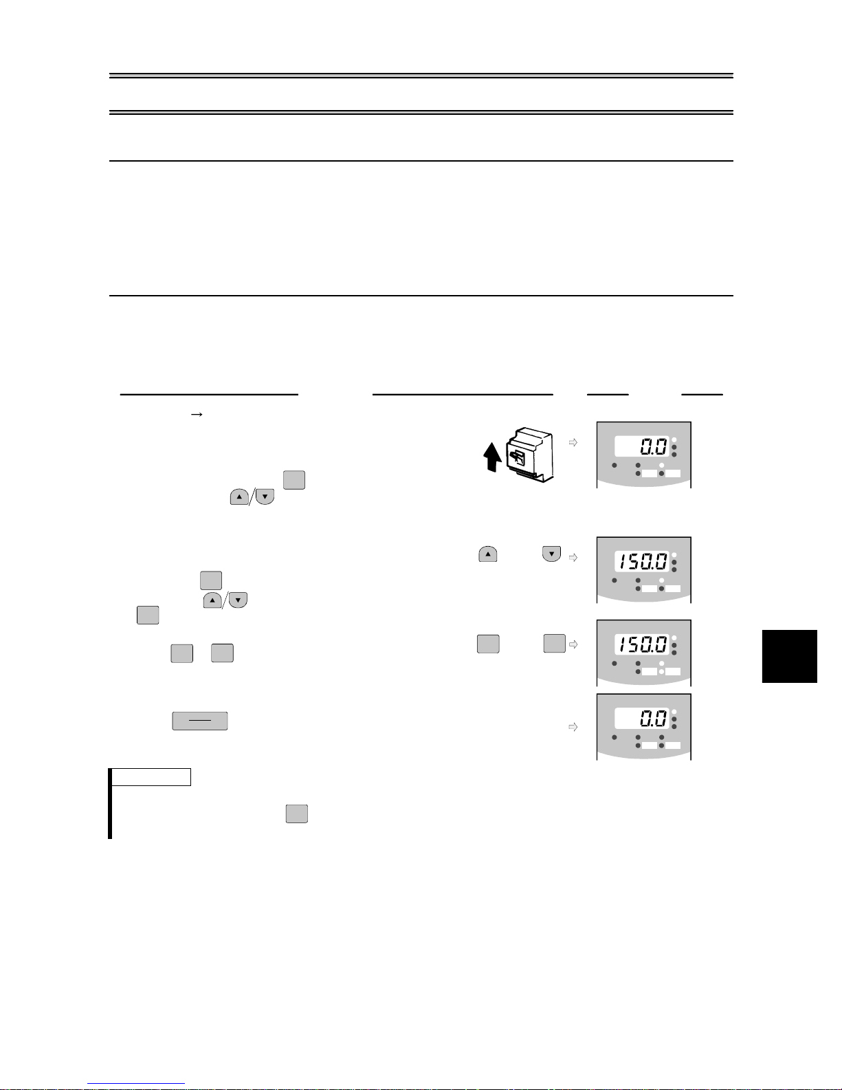
(1) Choosing PU operation mode (operation from the operation panel (FR-DU04-1)) and run-
ning at 150r/min
Operation
1.
Power on Operation mode check
The external operation mode (EXT) is selected when
switching power on with factory setting.
Make sure that the operation command indication "PU" is lit.
If it does not appear, press to choose the operation
MODE
ON
Display
-1
FR-DU04
MON EXT PU
CONTROL PANE L
REV FWD
Hz/r
A
V
mode, and press to choose the PU operation mode.
When the desired result is not obtained, set the PU operation
mode in Pr.79.
2.
Running speed setting
Set the running speed to 150r/min.
First, press to choose the speed setting mode.
MODE
(or)
FR-DU04
CONTROL PANE L
-1
MON EXT PU
REV FWD
Hz/r
A
V
Then, press to change the setting, and press
SET
to write the value.)
Start
3.
Press or .
FWD
REV
The motor starts. The mode is automatically switched
FWD
(or)
FR-DU04
REV
CONTROL PANE L
-1
MON EXT PU
REV FWD
Hz/r
A
V
to the monitoring mode and the output speed is displayed.
Stop
4.
Press .
STOP
RESET
The motor is decelerated to a stop.
FR-DU04
CONTROL PANE L
-1
MON EXT PU
REV FWD
Hz/r
A
V
REMARKS
• The operation speed can be changed by changing the preset speed during operation following the steps 2 an d 3 above.
• For monitor disp la y changes by , refer to page 27.
• To select the PU operation mode in Pr.79 "operation mode selection", set "1" in the parameter. Refer to page 52 for details.
MODE
3
RUN AND OPERATION
22
Basic operation (Speed setting, run,
speed meter adjustment)
PU jog operation
!
Hold down or
FWD
REV
to perform operation, and release it to stop.
1)Set Pr. 15 "jog speed setting" and Pr. 16 "jog acceleration/deceleration time".
2)Set PU jog operation. (Press to select the operation mode and press to switch to PU jog opera-
MODE
tion.)
3)Hold down the or key to perform operation.
FWD
REV
(If the motor remains stopped, check Pr. 13 "starting speed". The motor will not start if its setting is lower than
the starting speed.)
REMARKS
• If the motor does not rotate ⇒ ·Checki ng the PLG jumper connector (Refer to page12.)
• When you want to set th e speed to higher than 1500r/min, set Pr. 1 "maximum speed". (Refer to page 51.)
·Checking the phase sequence of the PLG cable (Refer to page 12.)
·For other cases, refer to Troubleshoo t ing on p age 82.
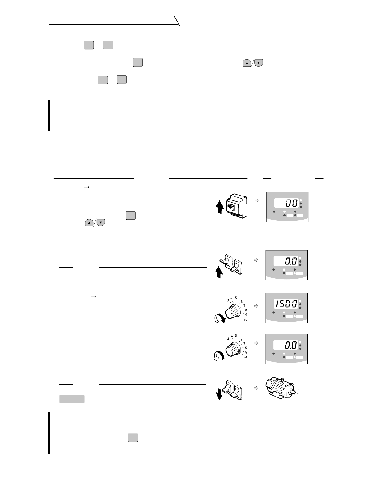
(2) Choosing external operation mode (operation using external speed setting potentiome-
ter and external start signals)
Running at 1500 r/min
!
•Operation command : start signals connected outside
•Speed setting : speed setting potentiometer connected outside
Operation Display
Power on Operation mode check
1.
The external operation (EXT) is selected when switching
power on with factory setting. Make sure that the operation
command indication "EXT" is lit.
If it does not appear, press to choose the operation mode,
MODE
and press to choose the external (EXT) operation mode.
When the desired result is not obtained, set the external
operation mode in Pr.79.
Start
2.
Turn on the start switch (STF or STR).
The operation status indication FWD or REV flickers.
CAUTION
The motor does not start if both t he forward and reverse
rotation switches are turned on. If both switches are
turned on during operation, the motor decelerates to a stop.
Acceleration Constant speed
3.
Slowly turn the potentiometer (speed setting potentiometer)
connected to across terminals 2-5 full clockwise.
The speed shown on the display increases gradually to
1500r/min.
Deceleration
4.
Slowly turn the potentiometer (speed setting potentiometer)
connected to across terminals 2-5 full counterclockwise.
The speed shown on the display decreases gradually to 0r/min.
The motor stops running.
5.
Stop
Turn off the star t switch (STF or STR).
CAUTION
When Pr. 75 "PU stop selecti on"= "14 to 17",
STOP
RESET
is valid.
ON
Forward
rotation
Forward
rotation
OFF
Reverse
rotation
Reverse
rotation
FR-DU04
FR-DU04
FR-DU04
FR-DU04
CONTROL PANE L
-1
MON EXT PU
REV FWD
CONTROL PANE L
-1
MON EXT PU
REV FWD
CONTROL PANE L
-1
MON EXT PU
REV FWD
CONTROL PANE L
-1
MON EXT PU
REV FWD
Stop
Hz/r
A
V
Hz/r
A
V
Hz/r
A
V
Hz/r
A
V
REMARKS
• The operation spee d of the external potentiome ter can be adju sted in Pr. 902 and Pr. 903 (bias and gain of the speed setting terminal). (Refer to page 47.)
• For monitor disp la y changes by , refer to page
• To select the external operation mode in Pr. 79 "operation mode selection", set "2" in the parameter. Refer to page 52 for
details.
MODE
27
.
23
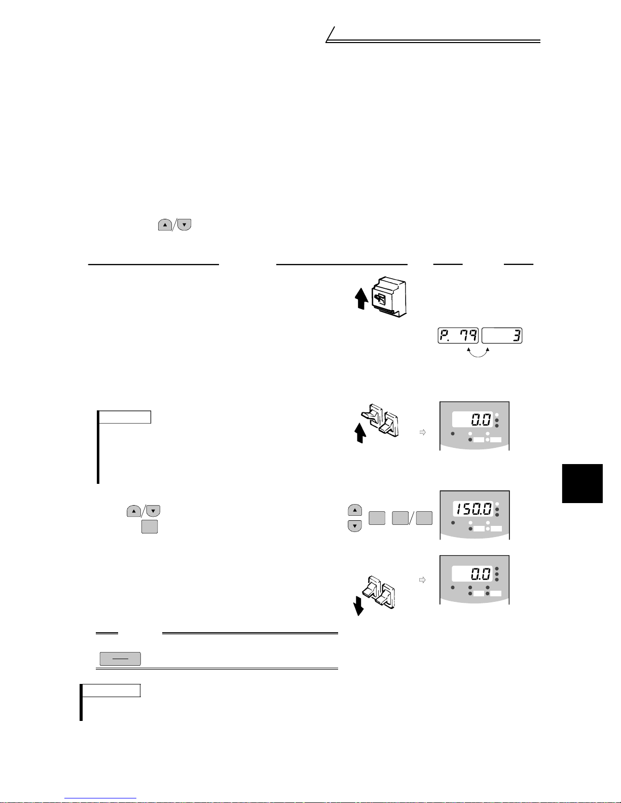
Basic operation (Speed setting, run,
speed meter adjustment)
External jog operation
!
Keep the start switch (STF or STR) on to perform operation, and turn it off to stop.
1)Set Pr. 15 "jog speed setting" and Pr. 16 "jog acceleration/deceleration time".
2)Select the external operation mode.
3)Switch on the jog signal. Keep the start switch (STF or STR) on to perform operation.
Assign the terminal used for the jog signal in any of Pr. 180 to Pr. 183 and Pr. 187
(input terminal function selection). (Refer to page 61.)
(3) Choosing external/PU combined operation mode 1 (operation using the external start
signal and operation panel)
! When setting the start signals from outside inverter (e.g. switches or relays) and the run-
ning speed from the operation panel (Pr. 79=3)
•Operation command : start signal connected outside
•Speed setting : of PU or multi-speed command (multi-speed command has priority)
For multi-speed command, refer to Pr.4 to Pr.6 on page 50.
Operation
1.
Power on
Switch power on.
Operation mode selection
2.
Set "3" in Pr. 79 "operation mode selection".
(Refer to page 52 for details of Pr.79.)
The combined operation mode is selected and the operation
status indication "EXT" and "PU" are lit.
Start
3.
Turn on the start switch (STF or STR).
The operation status indication "FWD" or "REV" is lit.
REMARKS
• The motor does not start if both the forward and
reverse rotation switches are turned on. If both
switches are turned on during operation, the motor
decelerates to a stop.
• Set the speed in the speed setting mode
4.
Running speed setting
Using , of PU, set the running speed to 150r/min
and press .
SET
The operation command indication FWD or REV is lit.
Stop
5.
Turn off the start switch (STF or STR).
The motor decelerates to stop.
The operation status indication "FWD" or "REV" is lit.
(Refer to page 27.).
ON
Forward
rotation
ON
SET REV FWD
Forward
rotation
Reverse
rotation
Reverse
rotation
Display
-1
FR-DU04
MON EXT PU
FR-DU04
MON EXT PU
-1
FR-DU04
MON EXT PU
REV FWD
-1
REV FWD
REV FWD
Flicker
CONTROL PANEL
CONTROL PANEL
CONTROL PANEL
Hz/r
A
V
3
Hz/r
A
V
Hz/r
A
V
CAUTION
When Pr. 75 "PU stop selection" = "14 to 17",
STOP
RESET
is valid.
REMARKS
When setting the start signal from the PU and speed setting signal from outside inverter, set "4" (combined operation mode 2
in Pr.79 "operation mode select i on".
OFF
RUN AND OPERATION
)
24
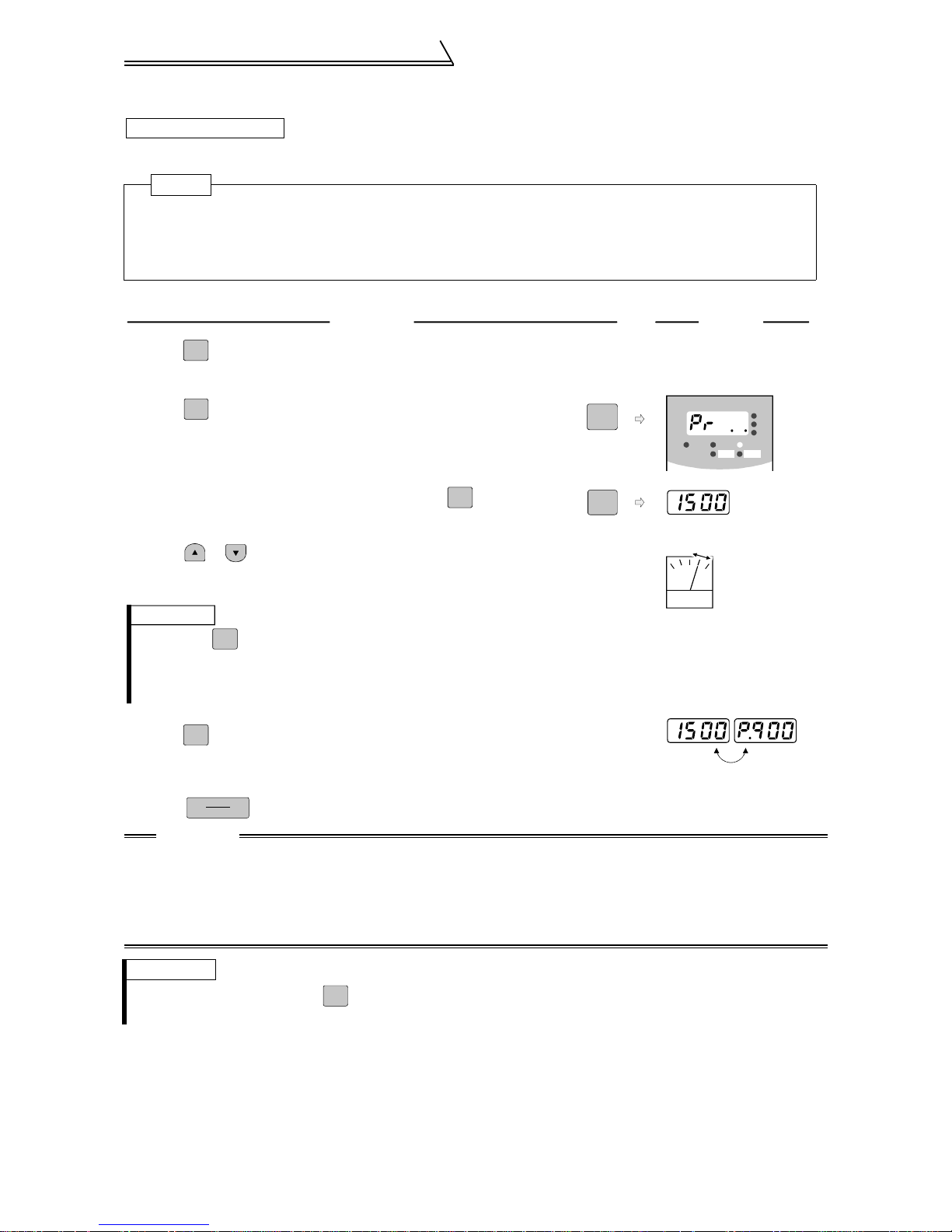
Basic operation (Speed setting, run,
speed meter adjustment)
3.2.2 Adjustment (calibration) of speed meter (meter)
Changing example
At the preset speed of 1500r/min, make adjustment so that the meter (analog meter)
deflects to full-scale. Calibrate the DA1 terminal (±10V).(in PU operation mode)
POINT
• Pr. 900 "DA1 terminal calibration" can be read by setting "1" (extended function parameter enable) in
Pr. 160 "extended function selection".
• Set Pr. 900 "DA1 terminal calibration".
• Set any of "1 to 3, 5 to 12, 17, 18, 21, 32 to 34 and 36" in Pr. 54 "DA1 terminal function selection" to
output a signal to the terminal DA1. (Refer to page 56)
Operation
FWD
Press to operate the inverter. (It is not necessary to
1.
Display
connect a m o t o r.)
2.
3.
MODE
Press to select the parameter setting mode.
Display the present operation speed by pressing to
SET
MODE
SET
FR-DU04
MON EXT PU
REV FW D
Hz¤r
A
V
CONTROL PANEL
-1
read Pr. 900.
Press or to adjust the meter pointer to
4.
a predetermined position. (Depending on the setting,
(Analog voltage meter)
it may take some time until the pointer moves.)
REMARKS
1. Pressing to start reverse rotation operation will move the meter pointer
REV
reversely (in the negative direction).
2. The terminal DA1 output will also keep displaying the monitor when the
inverter stops due to an alarm.
5.
SET
Press for about 1.5s.
This completes the setting.
Flicker ...
Press to stop the inverter.
6.
STOP
RESET
Parameter setting complete!!
CAUTION
1. When the speed meter is connected across terminals DA1-5 to monitor the speed, the outp ut of ter-
minal DA1 is saturated if the maximum output speed reaches or exceeds 1500r/min, with the factory
setting unchanged. Hence, the setting of Pr. 55 "speed monitoring reference" must be changed to the
maximum output speed. (Refer to page 56.)
2. Terminal DA2 can be adjusted in Pr. 901
3. For operation from the parameter unit (FR-PU04V), refer to the instruction manual of the FR-PU04V.
REMARKS
• For monitor disp la y changes by , refer to page 27.
• Calibration can be made also during external operation.
MODE
25
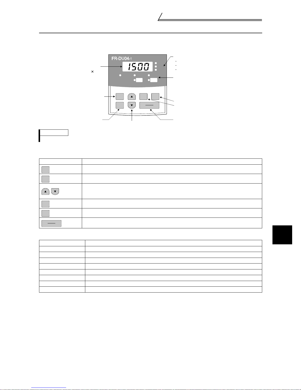
Names and functions of the opera-
tion panel
3.3 Names and functions of the operation panel
With the operation panel (FR-DU04-1), you can perform operation, set the speed, monitor the operation command
display, set parameters, display an error, and copy parameters.
isplay
ED 4 digits
Mode key
MON EXT PU
MODE
SET
etting key
Up/down keys
REMARKS
The ON of the LED is indicated by", and OFF by!.
Key indication
!
Key Description
MODE
SET
Select the operation mode or setting mode.
Determine the speed or pa ra meter setting.
• Used to increase or decrease the running speed consecutively. Hold down this key to change the
speed.
• Press thi s key in the setting mode to change the param et er set t in g consecutively.
FWD
Forward rotation comm and key.
CONTROL PANEL
FWD
REV
REV FWD
STOP
RESET
Hz/r
A
V
Unit indication
Hz/r (motor speed)
A (current)
V (voltage)
Operation status indication
Forward rotation key
Reverse rotation key
Stop/reset key
REV
STOP
RESET
Unit indication, operation status indication
!
Reverse rotation comman d key.
• Used to stop operation.
• Used to reset the inverter when the protective function (major fault) is activated to stop the output.
Indication Description
Hz/r Lit to indicate the outpu t s peed.
A Lit to indicate the current.
V Lit to indicate the voltage.
MON Lit in the monitor display mode.
PU Lit in the PU operation mode.
EXT Lit in the external operation mode.
FWD Flickers during forward rotation.
REV Flickers during reverse rotation.
3
RUN AND OPERATION
26

Names and functions of the opera-
tion panel
-1
REV FWD
MODE
CONTROL PANEL
Operation mode
Hz/r
A
V
FR-DU04
CONTROL PANEL
-1
MON EXT PU
REV FWD
Hz/r
A
V
3.3.1 Monitor display changed by pressing
Monitoring mode Parameter set ting mode
FR-DU04
CONTROL PANEL
-1
MON EXT PU
REV FWD
Speed setting mode (Caution)
Hz/r
A
V
FR-DU04-1
MODE MODE MODE MODE
CONTROL PANEL
MON EXT PU
REV FWD
Hz/r
A
V
FR-DU04
MON EXT PU
CAUTION
The speed setting mode appears only when the operation mode is the PU operation mode.
3.3.2 Monitoring
• Operation command indications in the monitoring mode
EXT is lit to indicate external operation.
PU is lit to indicate PU operation.
Both EXT and PU are lit to indicate PU/external combined operation.
• The monitor display can also be changed during operation.
Speed monitor Current monitor Voltage mon i tor Alarm monit or
FR-DU04
-1
MON EXT PU
MODE
CONTROL PANEL
REV FWD
Hz/r
FR-DU04
SET SET SET
A
V
SET
*
1
CONTROL PANEL
-1
MON EXT PU
REV FWD
FR-DU04
Hz/r
A
V
SET SET
*
1
-1
MON EXT PU
REV FWD
CONTROL PANEL
Alarm
absent
SET
Alarm
present
Hz/r
A
V
FR-DU04
MON EXT PU
*
1
Help mode
FR-DU04
-1
MON EXT PU
REV FWD
CONTROL PANEL
-1
REV FWD
SET
*
2
Hz/r
A
V
CONTROL PANEL
MODE
Hz/r
A
V
To 3.3.3 Speed setting (Caution 3)
CAUTION
1. Hold down marked *1 for more than 1.5 seconds to change the current monitor to the power-on
SET
monitor.
2. Hold down marked *2 for more than 1.5 seconds to display four errors including the latest one.
SET
3. In the external operation mode, it shifts to the parameter setting mode.
3.3.3 Speed setting
• Used to set the running speed in the PU operation mode.
To speed monitor
MODE
Speed setting mode
FR-DU04
MON EXT PU
MODE
REV FWD
Hz/r
A
V
Press / to change the set speed.
CONTROL PANEL
-1
To 3.3.4 Parameter setting method
Set speed change Set speed write
-1
FR-DU04
MON EXT PU
CONTROL PANEL
REV FWD
Hz/r
FR-DU04
SET
A
V
CONTROL PANEL
-1
MON EXT PU
REV FWD
Flicker
CONTROL PANEL
-1
Hz/r
A
V
FR-DU04
MON EXT PU
REV FWD
Hz/r
A
V
27

Names and functions of the opera-
tion panel
3.3.4 Parameter setting method (Example: Method to enable extended function
parameters)
• A parameter value may either be set by updating its parameter number or setting the value digit-by-digit using
.
• To write the setting, change it and press for 1.5 seconds.
Example: To change the Pr. 160 "extended function selection" setting from "0" (extended function parameter
invalid) to "1" (extended function parameter valid) (Refer to page 53 for details of Pr. 160.)
MODE
Press to choose the "parameter setting mode".
SET
Parameter setting mode
FR-DU04
CONTROL PANEL
-1
MON EXT PU
REV FWD
MODE
Hz/r
A
V
To 3.3.5 Operation mode
Current setting
SET
Most significant
digit flickers
SET
Flicker
1 time
×
or
9 times
×
0 to 9
Setting change
Press for
1.5 s
SET
Setting write
Middle digit
flickers
6 times
×
Least significant
digit flickers
or
4 times
×
SET
SET
0 to 9
If appears
1) When [FWD] or [REV] indication is lit,
stop operation by pressing or
STOP
RESET
turning off the forward rotation (STF) or
reverse rotation (STR) signal connected
to the control terminal.
2) You cannot set any value outside the parameter setting range.
Write a value within the setting range.
"1" (extended function parameter valid) has been set in Pr. 160.
If the value and parameter n umber do not flicker and
appears instead, you did not press for 1.5 seconds when
SET
writing the value.
Press once, press , and restart the setting from the beginning.
SET
MON EXT PU
REV FWD
3
3.3.5 Operation mode
External operation PU operation PU jog operation
FR-DU04
MODE
o 3.3.6 Help mode
REMARKS
If one operation mode ca nnot be switched to another, check the following items.
• External input signa ls ..... Make sure that the STF and STR signals are off.
• Parameter setting........... Check the Pr. 79 setting.
CONTROL PANEL
-1
MON EXT PU
REV FWD
When the Pr. 79 "operation mo de selecti on" setting is "0" (factory settin g), the inve rter is placed
in the external operation mo de at input po wer-on. A t this time, pres s on t he operatio n panel
twice and pr ess (press when the p arameter unit (FR-PU04V ) i s used) to switch to the P U
operation mode. For the ot her values (1 to 8), the operation mode is limited acco rdingly.
Hz/r
A
V
FR-DU04
CONTROL PANEL
-1
MON EXT PU
REV FWD
Hz/r
A
V
FR-DU04
CONTROL PANEL
-1
MON EXT PU
REV FWD
Hz/r
A
V
MODEMODE
RUN AND OPERATION
MODE
PU
28

Names and functions of the opera-
tion panel
3.3.6 Help mode
Alarm history Alarm history
FR-DU04
-1
MON EXT PU
MODE
CONTROL PANEL
REV FWD
Hz/r
A
V
clear
To 3.3.2 Monitoring
(1) Alarm history
Four past alarms can be displayed with .
("." is appended to the latest alarm.)
When no alarm exists, is displayed.
Latest alarm Second past Third past Fourth past
FR-DU04
SET
H/zr
A
V
SET
CONTROL PANEL
-1
MON EXT PU
REV FWD
Hz/r
A
V
At alarm
FR-DU04
CONTROL PANEL
-1
MON EXT PU
REV FWD
Hz/r
A
V
FR-DU04
-1
MON EXT PU
CONTROL PANEL
REV FWD
Parameter
clear
FR-DU04
-1
MON EXT PU
FR-DU04
-1
MON EXT PU
CONTROL PANEL
REV FWD
CONTROL PANEL
REV FWD
All clear Software version
read
Hz/r
A
V
FR-DU04
Hz/r
A
V
FR-DU04
CONTROL PANEL
-1
MON EXT PU
REV FWD
CONTROL PANEL
-1
MON EXT PU
REV FWD
Hz/r
FR-DU04
A
V
CONTROL PANEL
-1
MON EXT PU
REV FWD
Hz/r
A
V
Energization time Voltage Current Output speed
Hz/r
FR-DU04
A
V
CONTROL PANEL
-1
MON EXT PU
REV FWD
Hz/r
A
V
(2) Alarm history clear
Clears all alarm history.
CONTROL PANEL
-1
FR-DU04
MON EXT PU
REV FWD
Hz/r
SET SET
A
V
-1
FR-DU04
MON EXT PU
SET
CONTROL PANEL
REV FWD
Cancel
Flicker
Hz/r
A
V
MON EXT PU
REV FWD
Hz/r
A
V
FR-DU04
FR-DU04
CONTROL PANEL
-1
CONTROL PANEL
-1
MON EXT PU
REV FWD
Hz/r
A
V
29

Names and functions of the opera-
tion panel
(3) Parameter clear
Initializes the parameter values to the factory settings. The calibration values are not initialized.
(Parameter values are not cleared by setting "1" in Pr. 77 "parameter write disable selection".)
Flicker
FR-DU04
CONTROL PANEL
-1
MON EXT PU
REV FWD
Hz/r
FR-DU04
SET SET
A
V
REMARKS
Pr. 75, Pr. 82, Pr. 90 to Pr. 94, Pr. 96, Pr. 145, Pr. 171, Pr. 180 to Pr. 183, Pr. 187, Pr. 190 to Pr. 192, Pr. 195,
Pr.496, Pr.497, Pr.819, Pr. 849, Pr.868, Pr.880, Pr.890 to Pr.892, Pr. 900 to Pr. 905, Pr. 917 to Pr. 920, and Pr. 991 are not initialized.
(4) All clear
Initializes the parameter values and calibration values to the factory settings.
(Parameter values are not cleared by setting "1" in Pr. 77 "parameter write disable selection".)
CONTROL PANEL
-1
MON EXT PU
REV FWD
SET
Cancel
Hz/r
FR-DU04
A
V
CONTROL PANEL
-1
MON EXT PU
REV FWD
Hz/r
FR-DU04
A
V
CONTROL PANEL
-1
MON EXT PU
REV FWD
Hz/r
A
V
-1
FR-DU04
MON EXT PU
CONTROL PANEL
REV FWD
Hz/r
FR-DU04
SET SET
A
V
CONTROL PANEL
-1
MON EXT PU
REV FWD
SET
Cancel
Hz/r
A
V
REMARKS
Pr. 75, Pr. 145, Pr. 171, Pr. 496, Pr. 497 and Pr. 891 are not initialized.
-1
FR-DU04
MON EXT PU
CONTROL PANEL
REV FWD
Flicker
Hz/r
A
V
FR-DU04
MON EXT PU
REV FWD
Hz/r
A
V
CONTROL PANEL
-1
3
RUN AND OPERATION
30

Names and functions of the opera-
tion panel
3.3.7 Copy mode
By using the operation panel (FR-DU04-1), the parameter values can be copied to another inverter (only the FRV500 series).
1) Operation procedure
After reading the parameter values from the copy source inverter, connect the operation panel to the copy destination inverter, and write the parameter values.
After writing the parameter values to the copy destination inverter, always reset the inverter, e.g. switch power
off once, before starting operation.
Parameter setting mode
-1
FR-DU04
MON EXT PU
FR-DU04
-1
MON EXT PU
CONTROL PANEL
REV FWD
CONTROL PANEL
REV FWD
Hz/r
A
V
FR-DU04
FR-DU04
Hz/r
SET
A
V
Press for
1.5s
FR-DU04
CONTROL PANEL
-1
MON EXT PU
-1
MON EXT PU
SET SET SET
-1
MON EXT PU
REV FWD
CONTROL PANEL
REV FWD
(Caution 1)
CONTROL PANEL
REV FWD
Hz/r
A
V
Hz/r
A
V
Press for
1.5s
FR-DU04
Hz/r
A
V
FR-DU04
CONTROL PANEL
-1
MON EXT PU
REV FWD
Hz/r
A
V
(Caution 1) (Caution 1)
CONTROL PANEL
-1
MON EXT PU
REV FWD
Hz/r
A
V
FR-DU04
Press for
1.5s
FR-DU04
CONTROL PANEL
-1
MON EXT PU
REV FWD
CONTROL PANEL
-1
MON EXT PU
REV FWD
Hz/r
A
V
Hz/r
A
V
Parameter read Parameter write Parameter verify
After writing the parameter values,
always reset the inverter prior to
Connect to copy destination inverter.
the start of operation.
CAUTION
1. While the copy function is being activated, the monitor display flickers. The display returns to the litup state on completion of the copy function.
2. If a read error occurs during parameter read, "read error (E.rE1)" is displayed.
3. If a write error occurs during parameter write, "write error (E.rE2)" is displayed.
4. If a data discrepancy occurs during parameter verify, the corresponding parameter number and "verify error (E.rE3)" are displayed alternately. If the directly preset speed or jog speed setting differs,
"verify error (E.rE3)" flickers. Press to ignore this display and continue verify.
SET
5. When the copy destination inverter is not the FR-V500, "model error (E.rE4)" is displayed.
Reference: It is recommended to perform parameter read after completion of parameter setting. (When
performing auto tuning, it is recommended to perform read after completion of auto tuning.) When the
inverter has been changed, performing parameter write from the operation panel fitted to a new
inverter completes parameter setup.
31

Speed control operation
4CONTROL
This inverter can control a motor und er speed, torque or p osition control. (As required, set "1" (extended
function parameters valid) in Pr. 160 "extended function selection".)
Refer to page 28 for the setting method of Pr. 160 "extended function selection" and to page 54 for details.
(Since the factory setting of Pr. 77 is "0", perform parameter write in the PU mode or during a stop.)
4.1 Speed control operation
4.1.1 Speed control
Speed control is exercised to match the speed command and actual motor speed.
Speed response........ Maximum 800rad/s by internal processing and maximum 300rad/s (without adaptive
magnetic flux observer) by analog input signal are available (motor speed response to the
speed command).
4.1.2 Opera ti on tr a n sit i o n
Turning on the start signal increases the
!
speed up to the preset speed according to the
acceleration time.
Turning off the start signal decreases the
!
speed according to the deceleration time.
When the speed has decreased down to the
DC brake operation speed, operation
changes to 0 speed control or servo lock.
(Refer to page 66.)
Acceleration time
in Pr. 7
Speed
Start signal
UN signal
Pr. 13 "starting speed"
Speed command
Deceleration time in Pr. 8
Pr. 10 "DC injection
brake operation
speed"
REMARKS
• When the RT signal is off, Pr. 7 and Pr. 8 are acceleration time and deceleration time.
• When the RT signal is on, Pr. 44 and Pr. 45 (second acceleration/deceleration time) are acceleration/decelera-
tion time.
• Pr. 44 and Pr. 45 are valid when the RT signal is on, and Pr. 110 and Pr. 111 (third acceleration/deceleration
time) are valid when the X9 signal is on. When both the RT and X9 are on, Pr. 110 and Pr. 111 are valid.
4.1.3 Setting procedure
Perform secure wiring. (Refer to page 7.)
It is not necessary to set
Set the PLG. (Refer to page 12.)
Set the motor to be used. (Refer to page 19.)
Refer to page 19 for when the motor is one rank lower.
Set any of "0 (speed-control), 2 (speed-torque switchover), 4 (speed-position switchover)" in Pr. 800 "control system
selection" to make speed control valid. The parameter is factory-set to 0 (speed control). (Refer to page 53.)
Set the operation command. (Refer to page 33.)
the PLG when using the
Mitsubishi standard
motor (SF-V5R).
Test run (Refer to page 22.)
As required
1) Gain adjustment (Refer to page 43.)
<Perform easy gain tuning.>
2) Set the torque restriction value (Refer to page 33.)
4
CONTROL
Set the speed restriction during torque control.
32

Speed control operation
4.1.4 Operation command setting
(1) Forward and reverse rotation commands (terminals STF, STR)
1)Command from the operation panel (FR-DU04-1): Turn on or (Refer to page 22.).
FWD
2)External command: Turn the forward/reverse rotation command (terminal STF, STR)on. (Refer to page 23.)
(Turning both terminals STF and STR on or off will give a stop command.)
REMARKS
Use Pr. 79 "operation mode" to change the operation mode be tween operation pane l (PU) and external comm and
(EXT). (Refer to page 52.)
REV
(2) Speed command
1)Operation panel (FR-DU04-1) speed setting (Refer to page 22.)
REMARKS
Use Pr. 79 "operation mode selection " to change the operation mod e between operation panel (PU) and external
command (EXT). (Refer to page 52.)
2)External analog command (terminal 2 (or terminal 1))
Give a speed command using the analog signal input to terminal 2 (or terminal 1).
REMARKS
• Set Pr. 73 "speed setting signal" to change between the main speed and override of ter m in al 2.
( Refer to the Instruction Manual (detailed)).
• For the ad justment of bias/gain of ana log signal, set terminal 2 in Pr. 902 "speed s etting No. 2 bias" or Pr. 903
"speed setting No. 2 gain". (Ref e r t o pag e 47.)
• The function of terminal 1 changes according to the setting of Pr. 868 "terminal 1 function selection". For the factory
set function of terminal 1, ref er to th e Instruc tion Manual (detail ed). The functi on of this termina l is fac tory-set to adding auxiliary of the speed setting signal of terminal 2.
• Set the adjustment of bias/gain of terminal 1 in Pr. 917 "No. 1 terminal bias (speed)" or Pr. 918 "No. 1 terminal gain (speed)".
3)Multi-speed commands
The external signals (RH, RM, RL) may also be used to give speed command.
(The terminals are factory-set as follows. DI1 = RH, DI2 = RM, DI3 = RL)
REMARKS
• The RH, RM and RL signals are assign ed to terminals DI1 to DI4 an d STR using Pr. 180 to Pr. 183 and Pr. 187
(input terminal function selection).
• Speed control has the following priority:
maximum setting > Jog >speed jump> minimum setting > 12 bit digital (FR-A5AX) /1 6 bit digital (FR-V5AH) > 16 bit
digital (FR-V5AH) > multi-speed > opti on high-resolution output (FR-V5 AX) > PID control > analog input
CAUTION
When the speed command is to be given usin g t he analog comman d (termin al 2), turn off the extern al sig nals (RH, RM, RL). If any of external signals (RH, RM, RL) is on, the multi-speed commands are made valid.
4.1.5 Torque restriction
Select the setting method of output torque restriction during speed control from among the external analog input
terminal "3" or "1" (Pr. 868 "No.1 terminal function selection" = "2") or parameter settings using Pr. 810 "torque
restriction mode".
Torque restriction is factory-set to exercise by parameter settings, and the restriction level is 150%.
Parameter Name
803
810
Constant output region
torque char acteristi c
selection
Torque restriction input
method selection
Factory
Setting
0
0
Description
0: Motor output is made constant (torque is reduced)
1: Torque is made constant
You can select whether the torque restriction in the constant output
region to be constant torque restriction or constant output restriction.
(Refer to page 38.)
0: Internal torque restriction (torque restriction by parameter settings)
(Refer to page 34)
1: External torque restriction (torque restriction using No. 3 and No. 1
(option (FR-V5AX) No. 6 terminal ))
With the upper limit of torque restriction as set in Pr . 22, Pr . 812, Pr. 813
and Pr. 814, the analog input from the No. 3 termina l inp ut is used as
the torque restriction value on the driving side within the Pr. 22 setting
range. When regenerative torque restriction is assigned to the No. 1
terminal or option's No. 6 term i na l o n th e re generative side, the analog
input from the No. 1 terminal or No. 6 terminal is used as the torque
restriction.
33

Speed control operation
Parameter Name
22 Torque restriction level 150
812
813
814
815
816
817
Torque restriction level
(regeneration)
Torque restriction level
(3rd quadrant)
Torque restriction level
(4th quadrant)
Torque restriction level
2
Acceleration torque
restriction
Deceleration torque
restriction
Factory
Setting
9999
9999
9999
9999
9999
9999
Description
Set the torque restriction leve l in % for speed control or position co ntrol so
that the output torque does not exceed the predetermined value. (0 to
400%)
When Pr. 810 = 0, 1st quadrant Pr. 22
2nd quadrant Pr. 812
3rd quadrant Pr. 813
4th quadrant Pr. 814
Set the torque restrictio n le vel in % for regeneration. (0 to 400%)
Valid for regeneration when Pr. 810 = 0.
9999: Restricted to the Pr. 22 value.
Set the torque restriction le vel in % for 3rd quadrant. (0 to 400%)
Valid for reverse rotation driving when Pr. 810 = 0.
9999: Restricted to the Pr. 22 value.
Set the torque restrictio n le vel in % for 4th quadrant. (0 to 400%)
Valid for reverse rotation regeneration when Pr. 810 = 0.
9999: Restricted to the Pr. 22 value.
When the TL signal is on, the P r. 815 value is a torque rest riction value
regardless of Pr. 810.
Set the torque restriction level in % for all operations. (0 to 400%)
Valid when the TL terminal (torque restriction selection) input is provided.
9999: According to the Pr. 22 value.
Set the torque restriction value for acceleration.
9999: Same torque restri ct ion as at constant speed
Set the torque restriction value for deceleration.
9999: Same torque restri ct ion as at constant speed
(1) Torque restriction level
1) When Pr. 810 = 0
In the factory setting, restriction is made on
all quadrants on the Pr. 22 torque restriction
level. When you want to set the level on a
quadrant basis, change the corresponding
parameter value.
Torque restriction
+
Reverse
regeneration
Reverse
rotation
Reverse
driving
quad 4
(Pr. 814)
quad 3
(Pr. 813)
1500
r/min
-
quad 1
(Pr. 22)
quad 2
(Pr. 812)
1500
r/min
Forward
driving
Forward
rotation
Speed
Forward
regeneration
(2) Second torque restriction level
When the TL signal is on, the Pr. 815 value is a
!
torque restriction value regardless of the mode in
Pr. 810.
2) When Pr. 810 = 1
With the upper limit of torque restriction as set in Pr. 22,
the analog input from the No. 3 terminal input is used as
the torque restriction value within the Pr. 22 setting
range. When the torque restriction function is selected in
the regenerative mode with the No. 1 terminal selected,
the input from the No. 1 is used as the torque restriction
on the regenerative side. (Pr. 868=2)
Reverse
No. 1 input or Pr. 22
whichever is smaller
No. 3 input or Pr. 22
regeneration
Reverse rot ation
Speed
Reverse
driving
Reverse
regeneration
Pr. 815
Pr. 815
Reverse
driving
Reverse rotation
1500
r/min
Torque restriction
quad 4
quad 3
Torque restriction
quad 4
1500
r/min
quad 3
-
+
quad 1
quad 2
quad 1
quad 2
No. 3 input or Pr. 22
whichever is smaller
No. 1 input or Pr. 22
whichever is smaller
Pr. 815
1500
r/min
Pr. 815
Forward
driving
Forward rotation
1500r/min
Forward
regeneration
Forward
driving
+-
Speed
Forward
regeneration
Forward rotation
4
CONTROL
34

Speed control operation
Related parameters
TL signal terminal assignment ⇒ Set "26" in any of Pr. 180 to Pr. 183 and Pr. 187 (input terminal function selection).
REMARKS
• When an ana log sig nal is u sed to mak e exte rnal to rque restrict ion, r efer to page 4 7 for calibr ation o f the N o. 3 ter minal (Pr.
904 "torque command No.3 bias" and Pr. 905 "torque command No.3 gain").
• When an analog signal is used to make regenerative torque restriction from the No. 1 terminal, perform calibration of the No.
1 terminal. (Pr. 919 "No. 1 terminl a bias (torque/magnetic flux)", Pr. 920 "No. 1 terminl gain (torque/magnetic flux)") Refer to
page 47.
(3) Torque restrictions during acceleration and deceleration
You can set torque restrictions during acceleration and deceleration individually.
The following chart shows torque restrictions according to the settings of Pr. 816 "acceleration torque restriction"
and Pr. 817 "deceleration torque restriction".
After -60<preset speed-speed<60r/min
status has persisted f or one second,
acceleration/decele r ation ends and it
is judged as constant speed operation.
(Refer to page 61)
Speed
Torque restriction
value
Pr. 816 "acceleration to rque
restriction"
Preset speed-speed 60r/min
is judged as deceleration.
Constant speed
torque restriction
Acceleration Constant speed Deceleration
-60r/min preset speed-speed
is judged as deceleration.
Pr. 817 "deceleration torque
restriction"
4.1.6 Gain adjustment
As a simple tuning method, the Pr. 819 "easy gain tuning" function is available. (Refer to page 43.)
REMARKS
• For fine adj ust m ent of gain, refer to the Instruction Manual (det ai l ed ))
• Manual gain adjus t m ent (Pr. 820, Pr. 821, Pr. 830, Pr. 831)
• Speed feed forw ar d control and model adaptive speed control are al so available.
35

Torque control operation
S
O
4.2 Torque control operation
4.2.1 Torque control
Torque control is exercised to develop torque as set in the torque command. The motor speed becomes constant
when the motor output torque and load torque are balanced. For torque control, therefore, the speed is determined
by the load.
For torque control, the motor gains speed as the motor output torque becomes greater than the motor load. Here,
set the speed restriction value so that the motor speed does not increase too high. The speed restriction value is set
in the following method. When speed restriction is not set, the speed restriction value setting is regarded as 0r/min
to disable torque control.
(Toruque control is disabled under speed restriction. (Speed control is performed.))
4.2.2 Opera ti on tr a n sit i o n
Speed restriction val ue is
increased up to preset v alue
according to the Pr.7
"acceleration time" setting.
Speed restriction value
Speed restriction value is decreased
down to zero according to the Pr.8
"deceleration time" setting.
Speed
Speed
tart signal
Output torque
* Speed control is peformed during speed restriction. (thus, torque according to the command is not developed)
Speed restriction
*
Torque contro l
Speed restriction
Output torque is provided
according to the No. 3 terminal
setting.
REMARKS
When the load is smaller tha n t or que command, the speed increases up to th e speed restriction value.
! When "0" is set in Pr. 7 or Pr. 8 "acceleration/deceleration time"
Terminal STF
Speed
0r/min
utput torque
OFF ON
10V
0V
150%
0
Speed restriction value
Speed restriction
Torque control
Limit by the torque
restriction value
4
CONTROL
36

Torque control operation
(
(1) I/O signals
The following table indicates the operations of the signals.
Signal Terminal Name Remarks
External operation STF, STR signal
Start signal
Torque command As set in the torque command right selection parameter. Input torque command.
Speed restriction As set in the speed restriction selection parameter.
PU operation
Forward or reverse rotation from
PU04V or DU04
-1
(2) Operation example (Pr. 804=0)
Torque control is enabled if the actual speed is less than the speed restriction value.
When the actual speed reaches or exceeds the speed restriction value, speed restriction operation starts, torque
control is stopped, and speed control (proportional control) starts.
The following shows the operations in response to the analog input command from the No. 3 terminal.
Pr. 7
Speed restriction value
Start and stop are the same as under speed
control. A stop is made when the STF and
STR signals are both on.
Display SL and output OL signal during speed
restriction.
Pr. 8
STF
(Forward rotation
command)
RH
Speed restriction)
Speed restriction
operation
Torque control operation
Speed restriction
operation
(Speed control)
Torque
control
operation
Speed restriction
operation
1) When STF is turned on, the speed restriction value is increased according to the time set in Pr. 7.
2) Torque control operation is performed when the actual speed is less than the speed restriction value.
3) When the STF start signal is turned off, the speed restriction value is decreased according to the time set in Pr. 8.
4) For torque control, the actual speed becomes constant when the torque c ommand and load torque are balanced.
5) The motor torque developing direction is determined by the combination of the torque command input polarity
and start signal as indicated in the following table.
Torque Command Polarity
Positive torque command
Negative torque comman d
STF signal ON STR signal ON
Forward rotation direction (f or ward rotation
driving/reverse rotatio n re generation)
Reverse rotation direction (forward rotation
regeneration/reverse ro ta t io n dr iv ing)
Torque Developing Direction (Mode)
Reverse rotation direction (forward rotation
regeneration/reverse rotation driving)
Forward rotation dire cti on ( fo rward rotation
driving/reverse rotation regeneration)
REMARKS
When speed rest r ic tion operation starts, speed control i s exercised to enable internal t or que restriction (Pr. 22 "torque restriction level) (factory setting). Speed control may not be returned to torque control in this case. Torque restriction be set to external torque restriction (term i nals N o. 3, No. 1 and No. 6 (option FR-V5AX).
(Refer to Pr. 803 "constant output region torque characteristic selection" (page 33).)
37

4.2.3 Setting procedure
T
Set any of "1 (torque control), 2 (speed-torque switchover), 5 (position-torque switchover)" in
Pr. 800 "control system selection" to make torque
Set the speed restriction value. (Refer to page 39.)
As required
• Perform online auto tuning.
(if torque control accuracy needs to be improved) (Refer to page 46.)
Perform secure wiring. (Refer to page 7.)
Set the PLG. (Refer to page 12.)
Set the motor to be used. (Refer to page 19.)
Refer to page 19 if the motor is one rank lower.
valid. (Refer to page 53.)
control
Set the torque command. (Refer to page 38.)
Te st run (Refer to page 22.)
Torque control operation
It is not necessary to set
the PLG when using the
dedicated motor (SFV5R).
Set torque restriction during speed control.
4.2.4 Torque command right selection
Using Pr. 804 "torque command right selection", set the method by which the torque command will be given.
The torque command is factory set to the torque command connected across terminals 3-5.
(This parameter is an extended function parameter. Set "1" in Pr.160 "extended function selecion".)
Pr. 804 Setting Description
0
(factory setting)
1 Torque command by setting Pr. 805 or Pr. 806 (digital)
2
(FR-V5AP)
3
(FR-A5NC)
4
(FR-V5AH, FR-A5AX)
Torque command connected across termi nals 3-5 (analog)
Torque command by pulse train command
Torque command by using CC-Link.
Torque command from the option (digital)
Refer to the Instruction
Manual (detailed).
Fit an option to set these
values. R efer to the
instruction manual of
options (detailed) for
details.
4.2.5 "Torque command setting
Torque command selection
!
The figure on the next page shows how to give the torque command in the constant output region (extended
function parameter).
orque command
Base speed
Pr. 803 = 1: Constant torque
Pr. 803 = 0: Constant output
Speed
Parameter Name
Constant output
803
region torque
characteristic
selection
Factory
Setting
Setting
Range
00, 1
4
CONTROL
38

Torque control operation
(1) Calibration of torque command No. 3 terminal
Refer to the chart on the right for the relationship
between torque setting input voltage and output
Output torque
(Torque command)
150%
voltage. The torque setting input signal is in proportion to the output torque. Note that the motordeveloped torque varies with the motor temperature.
Use Pr. 904 and Pr. 905 to adjust bias/gain of
-10V
Bias
Pr. 904
0
Gain
Pr. 905
10V Terminal 3
the No. 3 terminal. (Refer to page 47.)
-150%
4.2.6 Speed restriction
Set the speed restriction value to prevent the motor from over speeding due to a smaller load torque than the torque
command value.
Parameter Name
807 S peed restriction selection 0 0, 1, 2
808 F or w ar d ro t at io n speed control 1500r/ m in 0 to 3600r/m in
809 Revers e ro t at ion speed control 9999 0 to 3600r/min, 9999
Select the speed restriction input method using Pr. 807.
Pr. 807 Setting
0
(factory setting)
1
2
Speed Restriction
Input Method
Same metho d as spee d
setting fo r speed
control
Pr. 808 Forward
rotation speed control
Pr. 809 Reverse
rotation speed control
Forward/reverse
rotation speed
restriction
(analog polarity
switchover speed
restriction)
(No. 1 terminal analog
input)
• Speed setting from the op eration panel
• Ex te rn al analog command (terminal 1, 2)
• M ul ti -s peed command
• Option (FR-V5AX etc.)
For both PU and external operations, the speed restriction changes according to
the acceleration/decel er at i on time. (Refer to 40 page)
According to the rotation direction, set the speed restriction in forward and
reverse rotation directio ns individually. When the reverse rotation speed
restriction is 9999, the set tin g is th e same as that of the torque restriction in
forward rotation directio n.
( Refer to the Instructi on M anual (detailed).)
The analog voltage of the No. 1 terminal input is used to make speed restriction.
For 0 to 10V input, set the forward rotation speed restriction. (The reverse
rotation speed restriction is Pr. 1 "maximum speed" .) For -10 to 0V input, set the
reverse rotation speed restriction. (The forward rotation speed restriction is Pr. 1
"maximum speed".) The maximum speed of both the forward and reverse
rotations is Pr. 1 "maximum speed". When No . 1 term i nal i npu t is selected, set
"5" in Pr. 868 "No. 1 terminal function assignment".
( Refer to the Instructi on M anual (detailed).)
Factory
Setting
Setting Range
Operation
Torque command
Speed restriction
Speed setting for
speed restriction
orward, reverse rotation
peed restriction parameter
Forward/reverse rotation
speed restriction
(analog polarity switchover
speed restriction)
input selection
0
1
2
Speed feedback<speed restrict ion value
+
+
-
Speed feedback speed restriction value
39
+
-
Speed control
(proportional control)
Torque
control
Motor
PLG

Torque control operation
S
s
b
r
(1) When Pr. 807 = 0
The speed command value during speed restriction
acts as a speed restriction level. At this time,
according to the acceleration/deceleration time set
in Pr. 7 "acceleration time" and Pr. 8 "deceleration
time", the restriction level is increased from 0r/min
upon start, and when the start signal turns off, the
speed restriction level is decreased from the then
speed restriction level to the DC injection brake
operation speed in Pr. 10 to a stop. The speed
restriction level at this time is shown below.
1)External analog speed restriction (terminal 1, 2)
The analog signal (0 to +10V (±10V)) input to terminal 2 (or terminal 1) is
used to give a speed restriction command.
REMARKS
• Set Pr. 73 "speed setting signal" to change between the main speed and override of term in al 2.
( Refer to the Instruction M anual (detailed).)
• If the above speed r estrictio n comma nd is g reater t han Pr. 1 "maximum s peed", t he spee d restri ction va lue is re garded as
the Pr. 1 "maximum speed" value. If the speed restriction command is smaller than Pr. 2 "minimum speed", the speed
restriction value is regarded as the Pr. 2 "minimum speed". Similarly when the speed restriction command is smaller than Pr.
13 "starting speed", the s peed restriction value is 0r/min.
• Set the speed restriction of terminal 1 using Pr. 868 "No. 1 terminal function selection".
( Refer to the Instruction M anual (detailed).)
2)Speed restriction on multi-speeds
The speed restriction command can also be set for the external signals (RH, RM, RL).
(The terminals are factory-set as follows. DI1 = RH, DI2 = RM, DI3 = RL)
REMARKS
The RH, RM and R L s i gnals are assigned to terminals DI1 t o DI 4 using Pr. 180 to Pr. 183 and Pr. 187 (input terminal fu nct i on
selection).
CAUTION
When speed restriction is to be made using the analog command (terminal 2), turn off the external signals (RH, RM, RL). If any of external signals (RH, RM, RL) is on, multi-speed restrictions are made valid.
peed setting acts as
peed restriction level in
oth forward rotation and
everse r o ta tio n.
Start signal
Pr. 7
Speed restriction operation
Pr. 8
Torque
contr o lla b le ra n g e
10E (+10V)
2 (0 to +10V)
5 (Analog com m on)
REMARKS
• Changing the terminal assignment in Pr. 180 to Pr. 183 and Pr. 187 may affect the other functions. Make setting after checking the funct ions of the cor responding terminals.
• If the value set in Pr. 187 is other than "9999", the external command cannot be used to perform reverse rotation operation.
To start reverse rotation, set "9999" (factory setting) in Pr. 187 to make the STR signal of terminal STR valid.
• When the above speed restriction com m and is great er than the Pr. 1 " maximum speed" value, th e speed restriction value is
the Pr. 1 "maximum speed" val ue, a nd whe n th e s peed r estri ction comma nd is les s th an th e Pr. 2 "minimum speed " v alue,
the speed restriction value is the Pr. 2 "minimum speed" value. When the speed restriction command is less than the Pr. 13
"starting speed" value, th e speed restriction value is 0r/min.
• When external speed restriction is to be made using an alog, calibrate th e No. 2 (No.1) term inal. Refer to Pr. 902 "speed
setting No. 2 bias" a nd Pr. 903 "speed setting No. 2 gain". Refer to Pr. 917 "No.1 t er m inal bias" and Pr. 918 "No.1 terminal
gain" for the No.1 terminal. (Refer to page 47.)
(2) For Pr. 807="1 or 2", refer to the Instruction Manual (detailed).
4.2.7 Optimum speed estimation and torque control accuracy improvement
To eliminate the temperature drift of torque under torque control, change the Pr. 95 "online auto tuning" setting to
"2". (Refer to page 46.)
For torque control, easy gain tuning has no effect.
When an unfavorable phenomenon such as torque pulsation occurs or when you want to exhibit the best
performance according to the machine, refer to the Instruction Manual (detailed) to perform a manual gain
adjustment (Pr.824 to Pr.827).
4
CONTROL
40

Position control operation
4.3 Position control operation
On this inverter, you can use parameter and pulse inputs to exercise position control.
Refer to the Instruction Manual (detailed) for details.
4.3.1 Position command from parameter setting
Position control is exercised using the position feed amounts set in Pr. 465 to Pr. 494.
4.3.2 Position command from PLC
Position control is exercised by connecting the PLC, such as the MELSEC-Q series PLC positioning module
(QD75), and the positioning control option (FR-V5AP) to the inverter.
41

Control mode switchover timing
4.4 Control mode switchover timing
Depending on a parameter setting change or whether the MC terminal turns on/off, the control mode switches at the
following timing.
Switchover Pattern
Speed Torque
S peed P o sitio n
Position Torque
Example: Speed
〈
The mode can be changed any time independently of whether the mo to r is at a st op or running
or the DC brake (servo lock) is operating.
The mode can be changed when the speed is equal to or lower than the low speed detection level.
When the speed is higher than the low speed detection level, changing the MC signal during
rotation will not sw itch the control mode to the other, and as soon as the speed falls to or below Pr.
865 "low speed detection level", the control mode is changed according to the terminal status.
Position, when Pr. 800 = 4
Low speed detection
level (Pr. 865)
STF
MC
Speed control Position control
Terminals and terminal functions changed by control mode switchover
!
The terminal functions vary with the control mode as indicated in the following table.
Classification
Contact input
signal
Contact out put ABC Alarm contact ←←
Open collector
output
Analog input
Analog output
*: Assumes that the Pr. 868 value is the factory setting.
REMARKS
• DI1 to DI4, STR terminal f unct ion selection ⇒ Pr. 180 to Pr. 183, Pr. 187 (input terminal function selection). (Refer to page 61.)
• DO1 to DO3, ABC terminal fun ction selectio n ⇒ Pr. 190 to Pr. 192, Pr. 195 (output terminal function selection). (Refer to page
61.)
• No. 1 terminal function selection ⇒ Pr. 868 "No. 1 terminal function assignment" ( Refer to the Instruction Manual
(detailed).)
• No. 1, 2, 3 terminal bias/gain adjustment ⇒ Pr. 902 to Pr. 905, Pr. 917, Pr. 918 (bias/ gai n adjustment) (Refer to page 47.)
• DA1, DA2 terminal function selection ⇒ Pr. 54, Pr. 158 (DA1, DA2 function selection) (Refer to page 56 (DA1) and page 60
(DA2).)
• DA1, DA2 terminal calibration ⇒ Pr. 900, Pr. 901 (DA1, D A2 t erminal calibra tion) (Refer to p age 25.)
• MC signal terminal assignment ⇒ Set "26" to any of DI1 to DI4 and STR using any of Pr. 180 to Pr. 183 and Pr. 187 (input ter-
minal function se l ect ion). (Refer to page 61.)
• For the change in terminals and terminal f unctions during position control, refer to the Instr uction Manual (detailed).
• Control system selection ⇒ Pr. 800 (Refer to page 53.)
Terminal
Name
STF Forward rotation command ←←
STR Reverse rotation command ←←
DI1 Multi-function input 1 ←←
DI2 Multi-function input 2 ←←
DI3 Multi-function input 3 ←←
DI4 Multi-function input 4 ←←
DO1 Mu lti -function output 1 ←←
DO2 Mu lti -function output 2 ←←
DO3 Mu lti -function output 3 ←←
2 Speed command input Speed restriction input
1*
3 Torque restriction input Torque command input
DA1 Multi-function monitor output 1 ←←
DA2 Multi-function monitor output 2 ←←
Speed Control Torque Control
Speed command
auxiliary input
Switchover Operation
〉
Description
Speed restriction
auxiliary input
Speed Control/Torque Con-
trol Switchover
(MC:ON/OFF)
Speed command/speed
restriction
Speed command/speed
restriction
Torque restriction/torque
command
4
CONTROL
42

Easy gain tuning
(
4.5 Easy gain tuning
The ratio of the load inertia to the motor inertia (load inertia moment ratio) is estimated in real time from the
torque command and speed during motor operation to automatically set the optimum gains for speed control/
position control from that ratio and response level setting.
4.5.1 Parameter
Parameter Name
818
819
Easy gain tu ning
response level setting
Easy gain tu ning
selection
Factory
Setting
Setting Range Remarks
2 1 to 15
00, 1, 2
4.5.2 Easy gain tuning execution procedure
1) Setting the response level in
Pr. 818 "easy gain tuning
response level setting"
Refer to the diagram on the right and
set the response level.
Increasing the value will improve
trackability to the command, but too
high value will generate vibration. The
relationship between the setting and
response level are shown on the right.
Pr. 818 setting
Response level
Guideline of machine
resonance frequency
(Hz)
Set the response level.
1: Slow response to 15: Fast res ponse
0: No tuning
1: With load estimation, with gain calculation
2: Manual load input (Pr. 880), with gain
calculation
1 23456789101112 131415
Slow
response
8 10 12 15 18 22 28 34 42 52 64 79 98 122 150
Large conveyor
Middle
response
Arm robot
General machine
tool, conveyor
Precision
machine tool
Fast
response
(2) Setting easy gain tuning enable in Pr. 819 "easy gain tuning selection"
Pr. 819 Setting Description
0
(factory setting)
1
2
(3) Start signal
FWD REV
Press or to estimate the load inertia ratio or calculate gain any time.
(The operation command for external operation is the STF or STR signal.)
REMARKS
When "1 or 2" is set in Pr. 819 "easy gain tuning selection" and then retur ned to "0", tuning results which are automatically set
in each parameter remain unchanged.
• Easy gain tuning is invalid.
• None of the load inertia ratio, position control gain and speed control gain valu es ar e updated.
• Easy gain tuning is valid.
• Each control gain is automa tica l ly set from t he load inertia ratio estimated during accelerati on/
deceleration operat ion and the Pr. 818 "easy gain tuning response level setting" value.
• Pr. 880 "load inertia ratio" is used as the initial value of the load inertia ratio for tuning. Estimated
value is set in Pr. 880 during tuning.
• Used when the load inertia ratio cannot be estimated well due to load disturbance and such or when
the load inertia ratio is known in advance, for example. At this time, the load inertia ratio is not
estimated and each cont ro l g ain is aut om atically set from the Pr. 880 "load inertia ratio" setting and
Pr. 818 "easy gain tuning response level setting" value.
43

Easy gain tuning
4.5.3 Precautions for easy gain tuning
(1) Checking the Pr. 800 "co n trol system selecti on" value
Easy gain tuning is valid only for the speed control/position control mode under PLG vector control.
It is invalid for torque control and V/F control.
Pr. 800 Setting Drive System Control Mode Easy Gain Tuning
0
Speed control
Valid
1 Torque control
2 Speed-torque switch over
PLG vector control
3 Positi on c ont r ol
4 Speed-position switchover
5 Position-torque switchover
20 V/F control Speed control
Invalid
When speed is select ed:
When torque is selecte d:
Valid
Valid
When position is sele ct ed:
When torque is selecte d:
Invalid
Valid
Invalid
Valid
Invalid
(2) Load inertia estimation restriction conditions
When "1" is set in Pr. 819 "easy gain tuning selection", the load inertia ratio may not be estimated well, e.g. it
takes a long time for estimation, if the following conditions are not satisfied.
• Time taken for acceleration/deceleration to reach 1500r/min is 5s or less.
• Speed is 150r/min or more.
• Acceleration/deceleration torque is 10% or more of the rated torque.
• Abrupt disturbance is not applied during acceleration/deceleration.
4.5.4 Automatically set parameters by easy gain tuning
Parameter Name Factory Setting Setting Range Remarks
422 Position loop gain 1 0 to 15 0
820 Speed cont ro l P ga in 60% 0 to 1000% 100% :2 00r ad/s
821
828
880 Load inertia r at io 7 0 , 1 to 200 times
Speed control
integration time
Model speed control
gain
0.333s 0 t o 10s
60% 0 to 1000%
Valid during position
control (1/s)
Valid during model
adaptive control
Setting value when easy
gain tuning load estimation
is perfor m ed
Inertia ratio with load only
4
REMARKS
Operation when the first or second function is selected
Load inertia estimation and gain calculation are performed only when the RT ter minal is off. The gain calculated is also
reflected only on these parameters. When the RT terminal is on, both the inertia estimation value and gain remain unchanged
from the previous values.
When some adjustments are required after executing easy gain tuning due to disturbance and such,
perform fine adjustment (adjustment of Pr. 820, Pr. 821) by manual input. (Set "0" (without gain tuning) in
Pr. 819 "easy gain tuning".)
If the fast responsiveness to the speed command is desired, consider exercising speed feed forward
control or model adaptive speed control. Refer to the Instruction Manual (detailed) for details.
CONTROL
44

Easy gain tuning
4.5.5 Easy gain tuning-related parameter operation
Refer to the following table for the parameter/gain re ad/write operation using Pr. 819 "easy gain tuning selection".
Pr. 819=1
calculation
Pr. 880
"load inertia"
Timing of writing load
inertia ratio and control
gains into E
Control gains
(Pr. 820, Pr. 821,
Pr. 828, Pr. 422)
2
PROM
Pr. 819=0
Without tuning
Read
Write
Read
Write
Setting is
displayed.
Setting can be
changed.
— Not written
Settings are
displayed.
Settings c an be
changed.
With inertia estimatio n, wi th gai n
Inertia estimation resul t is
displayed from the RAM.
Load inertia estimation result is
written. (Write is enabled only
during a stop.)
•Every hour after power-on
•When th e P r. 819 s etting is
changed to other than "1".
•When the vector con trol m ode is
changed to ot her drive systems
due to the Pr. 800 "control system
selection" setting change.
Gain cal c ulation result s (RAM) are
displayed.
Write disabled (operation er ror) Write disabled (operat i on er r or )
CAUTION
RAM data is erased when the power is not supplied or the inverter is reset.
Inertia as set in Pr . 880, wi th gain
Setting is displayed.
Setting can be changed.
When the Pr. 819 setting is
change d to "2"
When Pr. 880 "load ineritia ratio" or
Pr. 818 "easy gain tuning response
level setting" is changed
Settings are displaye d.
Pr. 819=2
calculation
45

Online auto tuning
4.6 Online auto tuning
Excellent torque accuracy is provided even if the secondary resistance value of the motor varies with the
!
rise of the motor temperature.
4.6.1 Parameters
• For the motor with PLG, set "2" in Pr. 95 "online auto tuning selection".
Parameter Name Factory Setting Setting Range Remarks
95 Online auto tuning selection 0 0, 1, 2
4.6.2 Pr. 95="1" (start-time tuning)
The current at a start is detected to compensate for the secondary resistance of the motor so that excellent
characteristics are provided regardless of the change in value of the secondary resistance of the motor with the rise
of the motor temperature.
CAUTION
1. Perform offline auto tuning in the mode with rotation before performing start-time tuning of the online
auto tuning.
4.6.3 Pr. 95 = "2" (normal tuning)/adaptive magnetic flux observer
0: No online auto tuning
1: Start-time tuning (at start-up)
2: Adaptive magnetic flux obs er ver (normal)
This function is effective for torque accuracy improvement when using the motor with PLG.
The current flowing in the motor and the inverter output voltage are used to estimate/observe the magnetic flux in
the motor.
The magnetic flux of the motor is always detected with high accuracy so that excellent characteristics are provided
regardless of the change in the temperature of the secondary resistance.
Set "2" when exercising PLG vector control.
CAUTION
1. For the SF-V5R, SF-JR (with PLG) or SF-HRCA (with PLG), it is not necessary to perform offline auto
tuning to select adaptive magnetic flux observer. (Note that it is necessary to perform offline auto
tuning (hon-rotation mode) for the wi ring length resistance to be reflected on the control when the
wiring length is long (30m or longer as reference).)
2. For using start-time tuning in vertical lift applications, examine the utilization of a brake sequence for
the brake opening timing at a start. Though the tuning ends in about a maximum of 500ms after a
start, torque is not provided fully during that period. Therefore, note that there may be a possibility of
gravity drop.
REMARKS
1. O nline auto t uning of th e start-time tuning does not operate if the MRS i s inp ut, if the p r eset speed i s less than t he starting
speed (Pr. 13), or if the starting conditions of th e i nverter are not satisfied, e.g. inverter error.
2. Online auto tuning of the start-time tuning does not operate during deceleration or at a restar t dur i ng DC br ake operation.
3. Invalid for jog operation.
4. The RUN signal is not output during online auto tuning of the start-time tuning. The RUN signal turns on at a start.
5. If the period from an inverter stop to a restar t is within 4 seconds, online aut o tuning of th e start-tim e tuning is performe d
but the tuning results are not re flected.
6. Automatic restart after instanta neous po wer failure overrides when autom atic restart a fter instant aneous pow er failure is
selected.
7. Zero current detection and output curre nt det ection are valid during online auto tuning.
4
CONTROL
46

Biases and gains of speed setting termi-
nals (Pr. 902 to Pr. 905, Pr. 917 to Pr. 920)
Biases and gains of speed setting term inals
4.7
(Pr. 902 to Pr. 905, Pr. 917 to Pr. 920)
Adjust the biases and gains of the speed setting No. 2, torque command No. 3 and multi-function No. 1
terminals.
The "bias" and "gain" functions are designed to adjust the relationship between the 0 to 10V input signal,
which is externally input for the setting of output speed, torque or magnetic flux.
Parameter Name Factory Setting Setting Range Remarks
902 Speed setting No. 2 bi as 0V 0r/min 0 to 10V 0 to 3600r/min
903 Speed setting No. 2 gai n 10V 1500r/min 0 to 10V 0 to 3600r/min
904
905
917
918
919
920
Torque command No. 3
bias
Torque command No. 3
gain
No. 1 terminal bias
(speed)
No. 1 terminal gain
(speed)
No. 1 terminal bias
(torque/magnetic flux)
No. 1 terminal gain
(torque/magnetic flux)
0V 0% 0 to 10V 0 to 400%
10V 150% 0 to 10V 0 to 400%
0V 0r/min 0 to 10V 0 to 3600r/min
10V 1500r/min 0 to 10V 0 to 3600r/min
0V 0% 0 to 10V 0 to 400%
10V 150% 0 to 10V 0 to 400%
Extended mode
(1500r/min)
(r/min)
Output speed
Bias
Pr. 902
Factory setting
Gain
Pr. 903
0
Setting signal
10V
-10V
(1500r/min)
(r/min)
Output speed
(150%)
Torque
(%)
Bias
Pr. 904
Pr. 919
Pr. 917
Setting signal
Inclination is as set in
Pr. 904 (Pr. 917, Pr. 919)
and Pr. 905 (Pr. 918, Pr . 920).
10V
Gain
Pr. 905
Pr. 918
Pr. 920
CAUTION
Torque command bias and gain can not be set by applying an external negative setting signal to the
torque command No. 3 or No. 1 terminal.
<Setting>
There are the following three methods to adjust the speed setting voltage bias and gain.
1) Method to adjust any point by application of a voltage to across terminals 2(1)(3) - 5
2) Method to adjust any point without application of a voltage to across terminals 2(1)(3) - 5
3) Method that does not adjust the bias voltage
(Example) Pr. 903 "speed setting No. 2 gain"
(Pr. 902 to Pr. 920 can be adjusted in the similar manner.)
<Adjustment procedure> Using the speed setting signal from the operation panel (FR-DU04-1) to make speed setting
(1) Power on (monitoring mode) (2) Choose the PU operation mode.
FR-DU04
CONTROL PANEL
-1
MON EXT PU
REV FWD
Hz/r
A
V
REMARKS
ON of the LED is indicated by , and OFF by .
1) Make sure that the inverter is in the PU operation
mode. (LED of PU is lit.) (Refer to page 28 for monitor transition.)
j
Operation mode (PU operation mode)
CONTROL PANEL
-1
FR-DU04
MON EXT PU
REV FWD
Hz/r
A
V
47

Biases and gains of speed setting termi-
C
nals (Pr. 902 to Pr. 905, Pr. 917 to Pr. 920)
2) Set 1 (PU operation mode) in Pr. 79 "operation mode selection". (Refer to page 52.)
Example: To change the external operation mode (Pr. 79 = 2) to the PU operation mode (Pr. 79 = 1)
MODE
Press one time.
Parameter setti n g mode
FR-DU04
CONTROL PANEL
-1
MON EXT PU
REV FWD
Hz/r
A
V
Most significant
digit flickering
SET SET
Middle digit flickering
7 times
×
0 to 9
SET
Least significant
digit flickering
9 times
×
0 to 9
Press for
Current setting Setting change
SET
1.5 s
SET
Setting write
If appears
Check that the forward rotation (STF)
Flicker
or reverse rotation (STR) signal connected
to the control terminal is not o n. If o n, tu rn it off .
"1" (PU operation mode) has been set in Pr. 79.
If appears, you did not press for
1.5 seconds when writing the v alue.
Press once, press , and make setting one
SET
more time.
(3) Read Pr. 903 to display the currently set gain speed.
Parameter setting mode
As in the procedure in (2)-2), press to
MODE
choose the "parameter setting mode".
SET
Least significant
digit flickering
3 times
×
FR-DU04
-1
MON EXT PU
CONTROL PANEL
REV FWD
Most significant
Hz/r
A
V
SET
digit flickering
9 times
×
Middle digit flickering
SET
Currently set gain spee d
FR-DU04
CONTROL PANEL
-1
MON EXT PU
REV FWD
Hz/r
A
V
0 to 9 0 to 9
(4) Set the gain speed in Pr. 903 and display the analog voltage A/D value across terminals 2-5 in %.
(To change to 1000r/min)
SET
SET
4
urrently set gain speed
FR-DU04
CONTROL PANEL
-1
MON EXT PU
REV FWD
Hz/r
A
V
• When not adjusting the gain voltage →→→→ To (5)-1
• When adjusting any point by application of voltage →
• When adjusting any point without application of voltage →→→→ To (5)-3
Gain speed changing
FR-DU04
CONTROL PANEL
-1
MON EXT PU
REV FWD
Hz/r
A
V
Use to change the
preset speed.
Press for
1.5 s
SET
Analog voltage A/D value (%) across term inals 2-5
FR-DU04
CONTROL PANEL
-1
MON EXT PU
REV FWD
Hz/r
A
V
In any of the following methods in (5) to (7), continue the setting
until the analog voltage A/D value flickers.
If you end the setting here, the gain speed changing is not
reflected.
→ To (5)-2
→ →
48
CONTROL

Biases and gains of speed setting termi-
nals (Pr. 902 to Pr. 905, Pr. 917 to Pr. 920)
(5)-1 Method to adjust only the gain speed and not to adjust the voltage
Analog voltage A/D value
(%) across terminals 2-5
FR-DU04
CONTROL PANEL
-1
MON EXT PU
REV FWD
Hz/r
A
V
(5)-2 Method to adjust any point by application of voltage to across terminals 2-5 (e.g. applied from external
potentiometer)
Press or once to display the
current analog voltag e adjustment value.
Example: When the analog
voltage adjustment
value is 100% (10V)
Press for 1.5 s.
SET
Flicker
Analog voltage A/D val ue
(%) across terminals 2-5
Apply a 10V voltage.
(Turn the external pote ntiometer connected
across terminals 2-5 to the maximum position.)
FR-DU04
CONTROL PANEL
-1
MON EXT PU
REV FWD
Hz/r
A
V
Press for 1.5 s
SET
In the maximum position of the
potentiometer, the value is nearly
Flicker
100(%).
(5)-3 Method to adjust any point without application of voltage to across terminals 2-5
(To change from 80% to 100%)
Analog voltage A/D value
(%) across terminals 2-5
FR-DU04
(6) Pressing shifts to the next parameter.
SET
CONTROL PANEL
-1
MON EXT PU
REV FWD
Press or once to
display the current analog
voltage adjustment value.
Hz/r
A
V
/
Press to set the gain voltage (%).
"0V = 0(%), 10V = 100(%)"
Flicker
/
Press for 1.5 s
SET
(7) Re-set the Pr. 79 "operation mode selection" value according to the operation mode being used.
CAUTION
1. Changing the Pr. 903 or Pr. 905 (gain adjustment) value will not change the Pr. 20 "acceleration/deceleration reference speed" value. (Refer to page 54 for Pr. 20.) The input of terminal 1 (speed setting
auxiliary input) is added to the speed setting signal.
2. For the operation procedure using the parameter unit ( FR-PU04V), refer t o the FR-PU04V in struction
manual.
3. When applying voltage for calibration, the difference of th e set in put voltage of bias and gain should
be 5% or more. If the difference is 5% or less, a setting error will occur.
Take care when setting any value other than "0" as the bias speed at 0V. Even if a speed command is
not given, merely turning on the start signal will start the motor at t he preset speed.
CAUTION
49

Function list (Simple m ode parameters)
5 PARAMETERS
5.1 Function list (Simp le mode parameters)
5.1.1 Simple mode parameter list
Minimum
Setting
Increments
0.1s/0.01s
0.1s/0.01s
Factory Setting
5s/15s
(1.5K to 5.5K
/7.5K to 55K)
5s/15s
(1.5K to 5.5K
/7.5K to 55K)
Reference
Page
51
51
Function
Parameter
1 Maximum speed
2 Minimum speed
4
5
6
Basic functions
7 Acceleration time
8 Deceleration time
72
77
functions
79
Operation selection
95
Auto
tuning
160
function
Additional
800
function
selection
Operation
818
system
Control
functions
819
Name
Multi-speed setting
(high speed)
Multi-speed setting
(middle speed)
Multi-speed setting
(low speed)
PWM frequency
selection
Parameter write
disable selection
Operation mode
selection
Online auto tuning
selection
Extended function
selection
Control system
selection
Easy gain tuning
response level
setting
Easy gain tuning
selection
Setting
Range
0 to 3600r/min 1r/min 1500r/min 51
0 to 3600r/min 1r/min 0r/min 51
0 to 3600r/min 1r/min 1500r/min 51
0 to 3600r/min 1r/min 750r/min 51
0 to 3600r/min 1r/min 150r/min 51
0 to 3600s/
0 to 360s
0 to 3600s/
0 to 360s
1 to 6 1 1 5 1
0,1,2 1 0 52
0 to 4,6 to 8 1 0 52
0,1,2 1 0 46
0,1 1 0 53
0 to 5, 20 1 0 53
1 to 15 1 2 43
0,1,2 1 0 43
Customer
Setting
At-a-glance Guide to Functions
• """":Usable function
• ×:Unusable function
• * :Functions that can be used for
parameter-set position feed forward
function
Vector Control
Speed
control
"""""
"""""
"""""
"""""
"""""
"""""
"""""
"""""
"""""
"""""
"""""
"""""
"""""
""""
""""
Torque
control
""
""
"
""
"
""
"
""
"
""
"
""
"
""
""
""
""
""
""
""
""
""
""
""
""
""
Position
control
×
×
"
""
×
×*
×*
×*
×*
×*
"
""
"
""
"
""
"
""
"
""
"
""
""""
""""
REMARKS
By setting "1" in Pr. 160 "extended function selection", the extended function parameters are made valid. (Refer to page 53).
PARAMETERS
5
50

Function list (Simple mode parameters)
5.1.2 Explanation of simple mode parameters
Refer to the separately available Instruction Manual (detailed) for details.
Pr. 1 "maximum speed", Pr. 2 "minimum speed"
Y ou can clamp the upper and lower li mits of the output
!
speed.
Maximum
speed
10V
Pr. 1
Minimum
speed
Pr. 2
Speed
Speed setting
CAUTION
Note that when you have set the minimum
speed, merely turning on the start signal will
start the motor at the preset speed, without the
input of the speed command, according to the
acceleration time setting.
Pr. 7 "acceleration time", Pr. 8 "deceleration time"
The time taken to reach the Pr. 20 acceleration/
!
deceleration reference speed (factory-set to 1500r/
min) from 0r/min is set as the acceleration time, and
the time taken to reach 0r/min from the Pr. 20 (factoryset to 1500r/min) speed is set as the deceleration
time.
r. 20
(r/min)
Running speed
r/min
Acceleration time
Pr. 7
Deceleration time
Time (s)
Pr. 8
Pr. 4 "multi-speed setting (high speed)"
Pr. 5 "multi-speed setting (middle speed)"
Pr. 6 "multi-speed setting (low speed)"
You can select any speed (RH, RM, RL) by simply
!
switching the external contact signal.
RH RM RL
High speed ON OFF OFF
Middle speed OFF ON OFF
Low speed OFF OFF ON
You can also set each speed to any value within the
!
range of 0 to 3600r/min during inverter operation.
Using the extended function, you can set up to 15
!
speeds.
Refer to the Instruction Manual (detailed) for the
setting method.
Pr. 72 "PWM frequency"
You can change the motor sound.
!
Setting Carrier Frequency
1
(factory setting)
24.5kHz
36.75kHz
49kHz
511.25kHz
613.5kHz
2.25kHz
REMARKS
Increasing the value reduces the sound level
!
but increases noise and leakage currents.
Refer to page 62 for Pr. 240 "soft PW M control".
!
51

Function list (Simple m ode parameters)
Pr. 77 "parameter write disable selection"
You can select whether write to variou s param eters can be perform ed or not. U se this fun ction to prevent para m eter
!
values from being rew ritten by m isoperation.
Setting Description
Parameter write can be performed. (Write is enabled only during a
0
stop in the PU operation mode.)
Parameter write cannot be performed. (Write to Pr. 22, Pr. 75, Pr. 77
1
and Pr. 79 "operation mode selection" is enabled.)
2 Write during operation is enabled.
REMARKS
• Parameters be low are w rite- enabled during operation even when Pr. 77=
Pr. 4 to Pr. 6, Pr. 22, Pr. 24 to Pr. 27, Pr. 52 to Pr. 56, Pr. 75, Pr. 77, Pr. 129, Pr. 130, Pr. 133, Pr. 134, Pr. 158, Pr. 160,
Pr. 232 to Pr. 240, Pr. 496, Pr. 497, Pr. 805, Pr. 806, Pr. 866, Pr. 900, Pr. 901 and Pr. 990.
• Parameters belo w are w rite-enabled even when Pr. 77=
Pr. 22, Pr. 75, Pr. 77 and Pr. 79
• Parameters be low are w rite- di sabled during operation even when Pr. 77=
Pr. 60, Pr. 71, Pr. 72, Pr. 79, Pr. 80 to Pr. 84, Pr. 90 to Pr. 96, Pr. 180 to Pr. 183, Pr. 187, Pr. 190 to Pr. 192, Pr. 195, Pr. 450,
Pr. 451, Pr. 453, Pr. 454, Pr. 800, Pr. 819, Pr. 849, Pr. 851, Pr. 852 Pr. 8 59 and Pr. 868
Pr. 79 "operation mode selection"
The inverter operation mode can be changed as desired between operation using external signals (external
!
operation), operation from the PU (FR-DU04
"1"
.
/FR-PU04V), combined operation of PU operation and external
-1
operation (external/PU combined operation), and computer link operation (when the FR-A5NR option is used).
Pr. 79 Setting Function
0
1 PU operation mode
2 External operation mode
3
4
6
7
8
At power-on, the inverter is in the external operation mode.
Operation can be performed by switching between PU and external operation.
External/PU
combined
operation m od e 1
External/PU
combined
operation m od e 2
Switch-over mode
Switch-over between PU operation, and external operation, and computer link operation (when the
FR-A5NR or any other communication option is used) can be done while running.
External operation mode (PU operation interlock)
X12 signal ON....... May be switched to PU operation mode (output stop during external operation)
X12 signal OFF......Switching to PU operation mode inhibited
Operation mode switching by the external signal (disallowed during operation)
X16 signal ON....... Switched to external operation mode
X16 signal OFF......Switched to PU operation mode
Speed command Start command
Set from the PU (FR-DU04
(direct setting, ) or external
signal input (multi-speed setting only)
Speed command Start command
External signal input (terminal 2, 1, jog,
multi-speed selectio n)
-1
Refer to the Instruction Manual (detailed) for details.
Pr. 95 "online auto tuning selection"
Refer to page 46 for details.
"0".
"2"
/FR-PU04V)
.
External signal input (terminal STF, STR)
Input from the PU (FR-DU04-1
(start command using , )
/FR-PU04V)
FWD REV
PARAMETERS
5
52

Function list (Simple mode parameters)
Pr. 160 "extended function display selection"
Set this parameter to display/set the extended function parameters.
!
Setting Description
0 Only the simple mode parameters are displayed.
1 All parameters are displayed.
REMARKS
Refer to page 54 for the parameters (extended function parameters) available when "1" is set in Pr. 160 "extended function display selection".
Pr. 800 "control system selection"
Select the inverter control system such as speed control, torque control or position control.
Setting Drive System Control Method Remarks
0
(factory setting)
1 Torque control
2
3 Position control
4
5
20 V/F control Speed contro l
Related par ameter s
MC signal term inal assign m ent
PLG vector control
⇒ Set "26" in any of Pr. 180 to Pr. 183 and Pr. 187 (input term inal fu nction selection). (Refer to page 61.)
REMARKS
Set the control system select ion of t he sec ond m otor in Pr. 451 "second motor control m eth od sel ection ". Ref er to the I nstruc tion Manual (detailed) for details.
Pr. 818 "easy gain tuning response level setting", Pr. 819 "easy gain tuning"
Refer to page 43 for details.
Speed control Factory setting
Speed control-torque control
switchover
Speed control-posi t ion control
switchover
Position control-tor que control
switchover
MC ON: Torque control
MC OFF: Speed control
MC ON: Position control
MC OFF: Speed control
MC ON: Torque control
MC OFF: Position control
53

Function list (Extended function
parameters)
5.2 Function li st (Extended function parameters)
Refer to page 50 for the function list of simple mode parameters.
The extended function parameters are made valid by setting "1" in Pr. 160 "extended function selection".
( Refer to page 28 for the setting method, and to the Instruction Manual (detailed) for details.)
Name Outline
Function
Parameter
Torque boost
0
(manual)
1 Maximum speed
2 Minimum speed
3 Base frequency
Multi-speed setting
4
(high speed)
Multi-speed setting
5
(middle speed)
Multi-speed setting
6
(low speed)
Basic functions
7 Acceleration time
8 Deceleration time
Electronic thermal O/
9
L relay
DC injection brake
10
operation speed
DC injection brake
11
operation time
DC injection brake
12
voltage
13 Starting speed
15 Jog speed setting
Standard operation functions
Jog acceleration/
16
deceleration time
17 MRS input selection
Base frequency
19
voltage
Acceleration/
20
deceleration
reference speed
Acceleration/
21
deceleration time
increments
Torque restriction
22
level
Multi-speed setting
24
(speed 4)
Multi-speed setting
25
Operation selection functions
(speed 5)
Multi-speed setting
26
(speed 6)
Multi-speed setting
27
(speed 7)
Multi-speed input
28
compensation
Factory
Setting
4%/3%/2%
Made valid for V/F control.
0 to 30%
0 to 3600r/min
0 to 3600r/min
Made valid for V/F control.
20 to 200Hz
0 to 3600r/min
0 to 3600r/min
0 to 3600r/min
0 to 3600s/ 0 to 360s
0 to 3600s/ 0 to 360s
0 to 3600s/ 0 to 360s
Set the stopping accuracy of positioning operation or the like according to the load by
adjusting the speed (0 to 1500r/min, 9999), time (0 to 0.5s) and voltage (0 to 30% ) that
are used to operate the braking torque at a motor stop for V/F control. (For vector
control, these functions follow pre- exci tation selection at n ot m ore than the sp eed i n Pr.
10.)
Set the speed at a start.
0 to 1500r/min
Speed command (0 to 1500r/min) and accelera ti on/de celerat ion i nclinati on (0 to 360 0s/
0 to 360s) for jog operation.
0: Turning MRS on stops output, 2: Turning MRS off stops output 0
Made valid for V/F control. Represents the magnitud e of the output volta ge at the base
frequency (Pr. 3).
8888: 95% of power supply voltage
9999: Same as power supply voltage
0 to 1000V, 8888, 9999
Represents the speed to be ref eren ced to i ncre ase o r d ecrea se th e spe ed fr om or to 0 r/
min in the time preset as the acceleration (Pr. 7) or deceleration time (Pr. 8).
1 to 3600r/min
0: 0.1s increments, 1: 0.01s increments 0
You can set the level of torque restriction.
0 to 400%
By setting a value other than “9999", set speeds 4 to 7.
ON/OFF of the contact signals (RH, RM, RL signals) are combined to change the
running speed in stages.
Speed 4 OFF ON ON
Speed 5 ON OFF ON
Speed 6 ON ON OFF
Speed 7 ON ON ON
0 to 3600r/min, 9999
The multiple speeds can be increased or overridden for compensation.
0: Without compensation
1: With compensation
RH RM RL
(3.7K or
les s / 5 .5K,
7.5K/11K
or more)
1500r/min
0r/min
1500r/min
750r/min
150r/min
5s/15s
1.5 K to
5.5K / 7.5K
to 55K
5s/15s
1.5 K to
5.5K / 7.5K
to 55K
5s/15s
1.5 K to
5.5K / 7.5K
to 55K
15r/min
4%/2%
(7.5K or
less/11K
or more)
15r/min
150r/min
1500r/
150%
50Hz
0.5s
0.5s
9999
min
9999
9999
9999
9999
0
At-a-glance Guide to Func-
Cus-
* :
tomer
for parameter-set position con-
Setting
control
tions
"""": Usable function
×: Unusable function
Functions that can be used
trol
Vector Control
Speed
Torque
Position
control
control
×××
"""""
""
"
""
"""""
""
"
""
×
×××
"""""
"
""
×*
"""""
"
""
×*
"""""
"
""
×*
"""""
"
""
×*
"""""
"
""
×*
"""""
""
"
""
""
"""""
"
""
×
"""""
"
""
×
×××
"""""
"
""
×
"""""
"
""
×
"""""
"
""
×
"""""
""
"
""
""
×××
"""""
"
""
"""""
"
""
""""
×
"""""
"
""
"""""
"
""
"""""
"
""
"""""
"
""
"""""
"
""
*
×
*
×
""""
*
×
*
×
*
×
*
×
×
PARAMETERS
Parameter
5
54

Function list (Extended function
parameters)
PARAMETERS
Function
Parameter
Acceleration/
29
deceleration pattern
Regenerative
30
function selection
31 Speed jump 1A
32 Speed jump 1B
33 Speed jump 2A
34 Speed jump 2B
Operation selection functions
35 Speed jump 3A
36 Speed jump 3B
37 Speed display
Up-to-speed
41
sensitivity
42 Speed detection
functions
Speed detection for
43
Output terminal
reverse rotation
Second acceleration/
44
deceleration time
Second deceleration
45
time
Second functions
Name Outline
Determines the frequency changing pattern for acceleration/deceleration.
0: Linear acceleration/deceleration
1: S-pattern acceleration/deceleration A
2: S-pattern acceleration/deceleration B
3: Backlash compensation acceleration/deceleration
4: S-pattern acceleration/deceleration C
Set when using the FR-ABR, FR-HC or FR-CV option for frequent start/stop operation.
0: Internal brake resistor, brake unit
1: Brake resistor (FR-ABR)
2: High power factor converter (FR-HC), power return common converter (FR-CV)
Set the speed ranges you want to avoid during constant-speed operation to avoid
resonance with the machine.
0 to 3600r/min, 9999
You can set the speed as a machine speed.
0, 1 to 9998
You can adjust the output signal on/off range when the output speed reaches the
running speed.
0 to 100%
You can adjust the speed detected.
0 to 3600r/min
You can change the speed detection level for forward or reverse rotation in vertical lift,
transfer and other applications.
0 to 3600r/min, 9999
Second function of the acceleration/deceleration time set in Pr. 7, Pr. 8.
0 to 3600s/0 to 360s
Second function of the deceleration time set in Pr. 8.
0 to 3600s/0 to 360s, 9999
Factory
Setting
0
0
9999
9999
9999
9999
9999
9999
0
10%
300r/min
9999
5s
9999
At-a-glance Guide to Func-
"""": Usable function
Cus-
tomer
Setting
×: Unusable function
* :
Functions that can be used
for parameter-set position con-
Vector Control
Speed
control
"""""
"""""
"""""
"""""
"""""
"""""
"""""
"""""
"""""
""""
"""""
"""""
"""""
"""""
tions
trol
Torque
Position
control
control
"
""
×
""
"
""
""
"
""
×
"
""
×
"
""
×
"
""
×
"
""
×
"
""
×
""
"
""
""
××
""
"
""
""
""
"
""
""
"
""
×*
"
""
×*
Second spee d
50
detection
functions
Output terminal
DU/PU main display
52
data selection
Display functions
PU level display data
53
selection
Set the speed at which the FB2 signal is output.
0 to 3600r/min
You can select the DU/PU main display data.
0, 100: Speed, output current, output voltage, alarm display
5: Preset speed
6: Output frequency
7: Motor torque
8: Converter output voltage
9: Regenerative brake duty
10: Electronic thermal relay load factor
11: Output current peak value
12: Converter output voltage peak value
17: Load meter
18: Motor exciting current
19: Position pulse
20: Cumulative energization time
23: Actual operation time
24: Motor load factor
32: To rque command
33: Torque current command
34: Motor output
35: Feedback pulse
38: Trace status
You can select the PU level display data.
0: No monitor
1: Speed
2: Output current
3: Output voltage
5: Preset speed
6: Output frequency
7: Motor torque
8: Converter output voltage
9: Regenerative brake duty
10: Electronic thermal relay load factor
11: Output current peak value
12: Converter output voltage peak value
17: Load meter
18: Motor exciting current
750r/min
0
1
"""""
""
""
"""""
""
""
"""""
""
""
"
""
"
""
"
""
55

Function list (Extended function
parameters)
Name Outline
Function
Parameter
DA1 terminal function
54
selection
Display functions
Speed monitoring
55
reference
Current monitoring
56
reference
57 Restart coasting time
58 Restart cushion time
Automatic restart
Remote setting
59
function selection
Additional function
Intelligent mode
60
selection
65 Retry selection
Number of retries at
67
alarm occurrence
Operation selection functions
68 Retry waiting time
Retry count display
69
erasure
Special regenerative
70
brake duty
You can select the monitor output DA1 data.
1: Speed
2: Output current
3: Output voltage
5: Preset speed
6: Output frequency
7: Motor torque
8: Converter output voltage
9: Regenerative brake duty
10: Electronic thermal relay load factor
11: Output current peak value
12: Converter output voltage peak value
17: Load meter
18: Motor exciting current
21: Reference output
32: To rque command
33: Torque current command
34: Motor output
36: Torque monitor (driving/regenerative polarity switching)
You can set the reference value of speed monitoring.
0 to 3600r/min
You can set the reference value of current monitoring.
0 to 500A
When power is restored after an instantaneo us power fai lure, you can start the invert er
without stopping the motor (in a coasting status). When this time (Pr. 57) elapses after
power was restored, the inverter begins to restart.
When you set "9999", the inverter will not restart. Generally, you may set "0", but you
can adjust the time (0, 0.1 to 5s, 9999) according to the load magnitude.
When the restart coasting time (Pr. 57) elapses, the output voltage is risen gradually.
Set this cushion time (Pr. 58) (0 to 60s).
Normally, you can perform operation with the factory settings, but you can adjust them
according to the load magnitude. Pr. 58 is valid only during V/F control.
You can make remote setting of the speed when the operation panel is located away
from the control box.
0: None
1: With remote setting function, with frequency setting storage function
2: With remote setting function, without frequency setting storage function
3: With remote setting function, without frequency setting storage function
(Turning STF/STR off clears remote setting)
Set when using the brake sequence control.
0: Normal operation mode
7: Brake sequence mode
(With mechanical brake opening completion signal input)
8: Brake sequence mode
(Without mechanical brake opening completion signal input)
You can select alarms for a retry to be made when the protective function is activated.
0:E.OC1 to 3, E.OV1 to 3, E.THM, E.THT, E.IPF, E.UVT, E.BF, E.GF, E.OHT, E.OLT,
E.OPT, E.OP1 to 3, E.PE, E.OS, E.OSD, E.OD, E.MB1 to 7
1:E.OC1 to 3
2:E.OV1 to 3
3:E.OC1 to 3, E.OV1 to 3
4:E.OC1 to 3, E.OV1 to 3, E.IPF , E .UVT, E.BF, E.GF, E.OLT, E.OPT, E.OP1 to 3, E.PE,
E.OS, E.OSD, E.OD, E. MB1 to 7
5:E.OC1, E.OC3
You can set the number of retries to be made when the protective function is activated.
0: Retry not made.
1 to 10: Without alarm output during retry operation
101 to 110: With alarm output during retry operation
You can set the waiting time from activation of the protective function to a retry.
0 to 10s
You can displ ay the cumulative number of successful re starts made by retr ies when the
protective function was activated.
0
Set to increase the regenerative brake duty when the FR-ABR option is used.
0 to 15%(1.5K or less), 0 to 30%(2.2K or more)
Factory
Setting
1
1500r/min
Rated
inverter
output
current
9999
1.0s
0
0
0
0
1s
0
0%
At-a-glance Guide to Func-
"""": Usable function
Cus-
tomer
Setting
×: Unusable function
* :
Functions that can be used
for parameter-set position con-
Vector Control
Speed
control
"""""
"""""
"""""
"""""
×××
"""""
""""
"""""
"""""
"""""
"""""
"""""
tions
trol
Torque
Position
control
control
""
"
""
""
""
"
""
""
""
"
""
""
"
""
×
"
""
×
××
"
""
×
"
""
×
"
""
×
"
""
×
""
"
""
""
PARAMETERS
Parameter
5
56

Function list (Extended function
parameters)
PARAMETERS
Name Outline
Function
Parameter
71 Applied motor
Operation selection functions
PWM frequency
72
selection
73 Speed setting signal
Factory
Setting
Set the motor to be used.
0, 3 to 8, 10, 13 to 18, 20, 23, 24, 30, 33, 34
Setting Motor Control Constants
0
3 Offline auto tuning
4 Offline auto tuning data utilization
Standard motor
5 Star connection direct input
(SF-JR etc.)
6 Delta connection direct input
7 Star connection direct input + offline auto tuning
8 Delta connection direct input + offline auto tuning
10
13 Offline auto tuning
14 Offline auto tuning data utilization
Constant-torque motor
15 Star connection direct input
(SF-HRCA etc.)
16 Delta connection direct input
17 Star connection direct input + offline auto tuning
18 Delta connection direct input + offline auto tuning
20
SF-JR(4P)-1.5kW or
23 Offline auto tuning
less
24 Offline auto tuning data utilization
30
(factory
SF-V5R vector control
setting)
inverter motor (includi ng
SF-VR type motor)
33 Offline auto tuning
34 Offline auto tuning data utilization
1 to 6 1
You can set the input specifications of terminals 1 and 2 and whether to use the
override function or not.
Pr. 73
Control
Setting
Mode
Override
0
4
Speed
control
10 × "
14
0
4
Tor que
control
10 ××
14
0, 4, 10, 14Position
control
*1 The value of terminal 1 (speed setting auxiliary input) is added to the main speed
setting signal of terminal 2.
*2 When override has been selected, terminal 1 acts as the main speed setting and
terminal 2 acts as the override signal (50 to 150% at 0 to 10V).
*3 When "30" or "31" is set in Pr. 128, terminal 2 acts as the PID set point function.
*4 When override has been selected, terminal 1 acts as speed rest riction and terminal
2 acts as the override signal.
"
"
"
"
No function No function No function
Inverter internal constants
Inverter internal constants
Inverter internal constants
Inverter internal constants
Function
Polarity
reversible
××
*2
*2
" Main speed setting Override signal
××
*4
*4
Terminal 1
(0 to ±10V)
Addition auxiliary
Speed command
× Main speed setting Override signal
Addition auxiliary
Speed command
Addition auxiliary
Speed restriction
× Speed restriction Override signal
Addition auxiliary
Speed restriction
× Speed restriction Override signal
Terminal 2
(0 to 10V)
*1
Main speed setting
*1
Main speed setting
Speed restriction
Speed restriction
*3
At-a-glance Guide to Func-
Cus-
* :
tomer
for parameter-set position con-
Setting
control
30
0
tions
"""": Usable function
×: Unusable function
Functions that can be used
trol
Vector Control
Speed
Torque
Position
control
control
"""""
""
""
"""""
""
""
"""""
"
""
"
""
"
""
×
57

Function list (Extended function
parameters)
Name Outline
Function
Parameter
Reset selection/
disconnected PU
75
detection/ PU stop
selection
Operation selection functions
Parameter write
77
disable selection
Reverse rotation
78
prevention selection
Operation mode
79
selection
80 Motor capacity
Number of motor
81
poles
Motor excitation
82
current (no load
current)
83 Rated motor voltage
Rated motor
84
frequency
90 Motor constant R1
91 Motor constant R2
Motor constants
92 Motor constant L1
93 Motor constant L2
94 Motor constant X
Online auto tuning
95
selection
Auto tuning setting/
96
status
Third acceleration/
110
deceleration time
Third deceleration
111
time
Third functions
Factory
Setting
You can select the reset i n put accep tance, disconne cted P U detect ion functi o n and PU
stop function.
Pr. 75
Setting
0 Reset input is always enabled.
1
2
3
14
15
16
17
0,1,2 0
You can prevent any reverse rotation fault resulting from the mis-input of the start
signal.
0: Both forward rotation and reverse rotation enabled, 1: Reverse rotation disabled, 2:
Forward rotation disabled
0 to 4,6 to 8 0
Set the motor capacity.
0.4kW to 55kW
Set the number of motor poles.
2,4,6
Used for tuning data utilization or direct input. 9999
Set the rated motor voltage.
0 to 1000V
Set the rated motor frequency.
20 to 200Hz
Used for tuning data utilization or direct input.
0,1,2 0
Perform motor auto tuning when a motor other than SF-V5R,SF-VR,SF-JR or SF-
HRCA is used.
0,1,101
Third function of acceleration/deceleration time set in Pr. 7, Pr. 8
0 to 3600/0 to 360s
Third function of deceleration time set in Pr. 8
0 to 3600/0 to 360s, 9999
Reset Selection
Reset input is enabled only when
the p rotectiv e fu n c tion is a c tiv a te d .
Reset input is always enabled. When the PU is
Reset input is enabled only when
the p rotectiv e fu n c tion is a c tiv a te d .
Reset input is always enabled.
Reset input is enabled only when
the p rotectiv e fu n c tion is a c tiv a te d .
Reset input is always enabled. When the PU is
Reset input is enabled only when
the p rotectiv e fu n c tion is a c tiv a te d .
Disconnected
PU Detection
If the PU is
disconnected,
operation will be
continued.
disconnected, the
inverter output is
shut off.
If the PU is
disconnected,
operation will be
continued.
disconnected, the
inverter output is
shut off.
PU Stop
Selection
Pressing
decelerates the motor
to a stop only in the
PU operation mode.
Pressing
decelerates the motor
to a stop in any of the
PU, external and
communication
operation modes.
STOP
RESET
STOP
RESET
Inverter
capacity
200V
60Hz
9999
9999
9999
9999
9999
9999
14
0
4
0
5s
At-a-glance Guide to Func-
"""": Usable function
Cus-
tomer
Setting
×: Unusable function
* :
Functions that can be used
for parameter-set position con-
Vector Control
Speed
control
"""""
"""""
"""""
"""""
"""""
"""""
"""""
"""""
"""""
"""""
"""""
"""""
"""""
"""""
"""""
"""""
"""""
"""""
tions
trol
Torque
Position
control
control
""
"
""
""
""
"
""
""
""
"
""
""
""
"
""
""
""
"
""
""
""
"
""
""
""
"
""
""
""
"
""
""
""
"
""
""
""
"
""
""
""
"
""
""
""
"
""
""
""
"
""
""
""
"
""
""
""
"
""
""
""
"
""
""
"
""
"
""
*
×
*
×
PARAMETERS
116 Third speed detection
functions
Output terminal
Set the speed at which the FB3 signal is output.
0 to 3600r/min
58
1500r/min
"""""
""
""
"
""
Parameter
5

Function list (Extended function
parameters)
PARAMETERS
Name Outline
Function
Parameter
117 Station number
Communication
118
speed
Stop bit length/data
119
length
Parity check
120
presence/absence
Number of
121
communication
retries
Communication
Communication functions
122
check time interval
123 Waiting time setti ng
CR, LF presence/
124
absence selection
128 PID actio n selection
PID proportional
129
band
130 PID integ ra l time
131 Upper limit
PID control
132 Lower limit
PID action set point
133
for PU operation
134 PID differen ti al ti me
Backlash
140
acceleration stopping
speed
Backlash
141
acceleration stopping
time
Backlash
Backlash
142
deceleration stopping
speed
Backlash
143
deceleration stopping
time
Speed setting
144
switchover
Station number setting for performi ng com munica tion oper ation fr om the PU connector
using a computer link.
0 to 31: Specify the station number of the inverter.
48:4800bps
96:9600bps
192:19200bps
0: Stop bit length 1 bit/data length 8
1: Stop bit length 2 bits/data length 8
10: Stop bit length 1 bit/data length 7
11: Stop bit length 2 bits/data length 7
0: None
1: With odd parity check
2: With even parity check
Set the permissible number of retries at data receive error occurrence. When you set
"9999", the inverter will not make an alarm stop if a communication error occurs.
0 to 10, 9999
Set the communication check time interval. If communication continues for longer than
the set time, the inverter will come to an alarm stop.
0: No communication
0.1 to 999.8s: Communication check time interval
9999: Check stop
When making communication, set any value other than 0 as the communication check
time interval.
Set the waiting time between data transmission to the inverter and response.
0 to 150ms
9999: Make setting using communication data.
0: Without CR/LF, 1: With CR/without LF, 2: With CR/LF
CAUTION
After setting the parameter, make a reset. The setting is reflected after the
reset is made. (Pr. 117 to Pr. 120, Pr. 123, Pr. 124)
Select the action of PID control.
10, 11, 30, 31
Set the proportional band for PID control.
0.1 to 1000%, 9999
Set the integral time for PID control.
0.1 to 3600s, 9999
Set the upper limit value for PID control.
0 to 100%, 9999
Set the lower limit value for PID control.
0 to 100%, 9999
Set the PID action set point value for PU operation.
0 to 100%
Set the PID differential time for PID control.
0.01 to 10s, 9999
Used for measures against the backlash of reduction gear, etc.
Acceleration stopping speed (0 to 3600r/min)
Acceleration stopping time (0 to 360s)
Deceleration stopping speed (0 to 3600r/min)
Deceleration stopping time (0 to 360s)
Set the number of motor poles when displaying the motor speed.
When Pr. 37 = 0
0, 2, 4, 6, 8, 10
Factory
Setting
0
192
1
2
1
0
9999
1
10
100%
1s
9999
9999
0%
9999
30r/min
0.5s
30r/min
0.5s
0
At-a-glance Guide to Func-
"""": Usable function
Cus-
tomer
Setting
×: Unusable function
* :
Functions that can be used
for parameter-set position con-
Vector Control
Speed
control
"""""
"""""
"""""
"""""
"""""
"""""
"""""
"""""
""""
""""
""""
""""
""""
""""
""""
"""""
"""""
"""""
"""""
"""""
tions
trol
Torque
Position
control
control
""
"
""
""
""
"
""
""
""
"
""
""
""
"
""
""
""
"
""
""
""
"
""
""
""
"
""
""
""
"
""
""
××
××
××
××
××
××
××
"
""
×
"
""
×
"
""
×
"
""
×
""
"
""
""
145 Parameter for the option (FR-PU04V)
Display functions
Output current
150
151
152
Current detection
153
detection level
Output current
detection t ime
Zero current
detection level
Zero current
detection t ime
Set when outputting the output current detection signal.
0 to 200% (Pr.150)
0 to 10s (Pr. 151)
Set when outputting the zero current detection signal.
0 to 200.0% (Pr.152)
0 to 1s (Pr. 153)
59
150%
0
5.0%
0.5s
"""""
""
""
"""""
""
""
"""""
""
""
"""""
""
""
"
""
"
""
"
""
"
""

Function list (Extended function
parameters)
Function
Parameter
Stall prevention
156
operation selection
Sub functions
OL signal output
157
timer
DA2 terminal function
158
selection
Display functions
Extended function
160
selection
Automatic restart
after instantaneous
162
power failure
selection
First cushion time for
163
restart
First cushion voltage
Auto m a tic res tart afte r
164
instantaneous power failure
for restart
Restart current
165
restriction level
Name Outline
You can make setting to prevent the inverter from an overcurrent trip (prevent the fastresponse current restriction from be ing acti va ted) and/or set the OL signal ou tput d el ay
if stall prevention is activated by an overcurrent or an excessive current flows due to
sudden fluctuation of load, ON-OFF of the running inverter output side or the like.
Fast-Response Current
Setting
0
1
2
3
4
5
6
7
8
9
10
11
12
13
14
15
16
17
18
19
20
21
22
23
24
25
26
27
28
29
30
31
Driving
Regener-
100
ation
Driving
101
Regener-
ation
Set whether to output the overload alarm signal (OL signal) immediately or after a
preset period of time when an overload status has occurred.
0 to 25s, 9999
Select the monitor output DA2 data.
1: Speed
2: Output current
3: Output voltage
5: Preset speed
6: Output frequency
7: Motor torque
8: Converter output voltage
9: Regenerative brake duty
10: Electronic thermal relay load factor
11: Output current peak value
12: Converter output voltage peak value
17: Load meter
18: Motor excitation current
21: Reference output
32: To rque command
33: Torque current command
34: Motor output
36: Torque monitor (driving/regenerative polarity switching)
0,1 0
Valid during V/F control
You can select the method for automatic restart after instantaneous power failure.
0: With speed search
1: Without speed search
10: Speed search initiated per start
Set the first cushion time for restart (0 to 20s), first cushion voltage for restart (0 to
100%) and restart current restriction level (0 to 200%) when a slight overload status
has occurred at an automatic restart after instantaneous power failure.
Restriction
: Activated
""""
!!!!
: Not ac tiv ate d
"""""
!!!!
"""""
!!!!
"""""
!!!!
"""""
!!!!
"""""
!!!!
"""""
!!!!
"""""
!!!!
"""""
!!!!
""""
!!!!!
""""
!!!!!
""""
!!!!!
""""
!!!!!
""""
!!!!!
""""
!!!!!
""""
!!!!!
""""
!!!!!
"""""
!!!!
!!!!
!!!!
OL Signal O utput
""""
: Operation continued
!!!!
: Operation not continued
"
""
""""
"
""
""""
"
""
""""
"
""
""""
"
""
""""
"
""
""""
"
""
""""
"
""
""""
!!!!
!
!!
!!!!
!
!!
!!!!
!
!!
!!!!
!
!!
!!!!
!
!!
!!!!
!
!!
!!!!
!
!!
!!!!
!
!!
"
""
""""
""""
""""
Factory
Setting
1
0
1
0
0s
0%
150%
At-a-glance Guide to Func-
"""": Usable function
Cus-
tomer
Setting
×: Unusable function
* :
Functions that can be used
for parameter-set position con-
Vector Control
Speed
control
"""""
"""""
"""""
"""""
×××
×××
×××
×××
tions
trol
Torque
Position
control
control
""
"
""
""
""
"
""
""
""
"
""
""
""
"
""
""
PARAMETERS
Parameter
5
60

Function list (Extended function
parameters)
PARAMETERS
Name Outline
Function
Parameter
168
Maker setting parameters. Do not make setting.
169
Maintenance
functions
Actual operation hour
171
meter clear
Initial
monitor
DI1 terminal function
180
selection
DI2 terminal function
181
selection
DI3 terminal function
182
selection
DI4 terminal function
183
selection
Ter mina l assignme nt functions
STR terminal function
187
selection
DO1 terminal function
190
selection
DO2 terminal function
191
selection
DO3 terminal function
192
selection
Terminal assignment functions
A,B,C terminal
195
function selection
You can clear the actual operation hour meter. 0
You can select the following input signals.
0: RL (multi-speed low-speed operation command) → Pr. 180 factory setting
1: RM (multi-speed middle-speed operation command) → Pr. 181 factory setting
2: RH (multi-speed high-speed operation command) → Pr . 182 factory setting
3: RT (second function selection) → Pr. 183 factory setting
5: JOG (jog operation selection)
8: REX (multi-speed 15 speeds selection)
9: X9 (third function selection)
10: X10 (FR-HC,FR-CV connection (inverter run enable signal))
11: X11 (FR-HC connection (instantaneous power failure detection)
12: X12 (PU operation external interlock)
14: X14 (PID control valid)
15: BRI (brake release completion signal)
16: X16 (PU operation-external operation switching)
20: X20 (S-pattern acceleration/deceleration C switching terminal)
22: X22 (orientation command)
23: LX (pre-excitation/servo on)
24:MRS(output stop)
25: STOP (start self-holding selection)
26: MC (control mode switching)
27: TL (torque restriction selection)
42: X42 (torque bias selection 1)
43: X43 (torque bias selection 2)
44: X44 (P control selection (P/PI control switching))
9999: No function (STR when set in Pr. 187)
You can select the followin
0 (positive logic) → Pr. 190 factory setting, 100 (negative logic): RUN (inverter running)
1 (positive logic) → Pr. 191 factory setting, 101 (negative logic): SU (up to speed)
2 (positive logic) → Pr. 192 factory setting, 102 (negative logic): IPF (instantaneous
power failure or undervoltage)
3 (positive logic), 103 (negative logic) : OL (overload alarm)
4 (positive logic), 104 (negative logic) : FU (output speed detection)
5 (positive logic), 105 (negative logic) : FU2 (second output speed detection)
6 (positive logic), 106 (negative logic) : FU3 (third output speed detection)
7 (positive logic), 107 (negative logic) : RBP (regenerative brake prealarm)
8 (positive logic), 108 (negative logic) : THP (electronic thermal alarm prealarm)
10 (positive logic), 110 (negative logic) : PU (PU operation mode)
11 (positive logic), 111 (negative logic) : RY (inverter operation ready)
12 (positive logic), 112 (negative logic) : Y12 (output current detection)
13 (positive logic), 113 (negative logic) : Y13 (zero current detection)
14 (positive logic), 114 (negative logic) : FDN (PID lower limit)
15 (positive logic), 115 (negative logic) : FUP (PID upper limit)
16 (positive logic), 116 (negative logic) : RL (PID forward/reverse rotation output)
20 (positive logic), 120 (negative logic) : BOF (brake opening request)
25 (positive logic), 125 (negative logic) : FAN (fan failure output)
26 (positive logic), 126 (negative logic) : FIN (fin overheat prealarm)
27 (positive logic), 127 (negative logic) : ORA (orientation completion)
30 (positive logic), 130 (negative logic) : Y30 (forward rotation output)
31 (positive logic), 131 (negative logic) : Y31 (reverse rotation output)
32 (positive logic), 132 (negative logic) : Y32 (regenerative status output)
33 (positive logic), 133 (negative logic) : RY2 (operation ready 2)
34 (positive logic), 134 (negative logic) : LS (low speed output)
35 (positive logic), 135 (negative logic) : TU (torque detection)
36 (positive logic), 136 (negative logic) : Y36 (in-position)
37 (positive logic), 137 (negative logic)) : MT (maintenance timer output)
40 (positive logic), 140 (negative logic) : Y40:(trace status)
41 (positive logic), 141 (negative logic) : FB (speed detection)
42 (positive logic), 142 (negative logic): FB2 (second speed detection)
43 (positive logic), 143 (negative logic) : FB3 (third speed detection)
44 (positive logic), 144 (negative logic) : RUN2 (second inveter operating)
96 (positive logic), 196 (negative logic): REM (remote output)
97 (positive logic), 197 (negative logic) : ER (minor fault output 2)
98 (positive logic), 198 (negative logic) : LF (minor fault output)
99 (positive logic) → Pr. 195 factory setting, 199 (negative logic): ABC (alarm output)
9999: No function
g output signals.
Cus-
Factory
tomer
Setting
Setting
0
1
2 "
3
9999
0
1
2 "
99
At-a-glance Guide to Func-
* :
for parameter-set position con-
tions
"""": Usable function
×: Unusable function
Functions that can be used
trol
Vector Control
Speed
Torque
control
"""""
"""""
"""""
""
""
"""""
"""""
"""""
"""""
""
""
"""""
Position
control
control
""
"
""
""
""
"
""
""
""
"
""
""
""
"
""
""
""
"
""
""
""
"
""
""
""
"
""
""
""
"
""
""
""
"
""
""
""
"
""
""
61

Function list (Extended function
parameters)
Function
Parameter
Multi-speed setting
232
(speed 8)
Multi-speed setting
233
(speed 9)
Multi-speed setting
234
(speed 10)
Multi-speed setting
235
(speed 11)
Multi-speed setting
236
(speed 12)
Multi-speed setting
Multi-speed operation
237
(speed 13)
Multi-speed setting
238
(speed 14)
Multi-speed setting
239
(speed 15)
240 Soft-PWM setting
Sub functions
Cooling fan operation
244
selection
250 Stop selection
function
Stop selection
Name Outline
By setting any value other than "9999", set speeds 8 to 15.
This function is designed to change the running speed in stages by changing the ON/
OFF combination of the contact signals (RH, RM, RL, REX signals).
Speed 8 OFF OFF OFF ON
Speed 9 OFF OFF ON ON
Speed 10 OFF ON OFF ON
Speed 11 OFF ON ON ON
Speed 12 ON OF F OFF ON
Speed 13 ON OF F ON ON
Speed 14 ON ON OFF ON
Speed 15 ON ON ON ON
0 to 3600r/min, 9999
You can select to exercise Soft-PWM control and long wiring mode. When Soft-PWM
control is made valid, you can change the metallic tone of motor sound into an
unoffending complex tone. Surge voltage is surpressed in the long wiring mode
regardless of the wiring length between the inverter and motor. (When operating a
400V motor with wiring length of 40m or more, select long wiring mode.)
0: Soft-PWM control invalid, long wiring mode invalid
1: Soft-PWM control valid (when Pr. 72 = "1 or 2"), long wiring mode invalid
10: Soft-PWM control invalid, long wiring mode valid (carrier frequency is 2.25Hz *)
11: Soft-PWM control valid, long wiring mode valid (carrier frequency is 2.25Hz *)
You can control the operation of the cooling fan built in the inverter.
0: The fan is always operated at power-on of the inverter.
1: The fan is always on while the inverter is running . During a stop, t he inverter statu s is
monitored and the fan switches on-off according to the temperature.
Set to allow the motor to be coasted to a stop by turning off the start command during
V/F or speed control.
0 to 100s: Coasting to stop
9999: Deceleration to stop
RH RM RL REX
*The Pr.72 "PWM frequency selection" setting is made invalid.
Factory
Setting
9999
9999
9999
9999
9999
9999
9999
9999
10
0
9999
At-a-glance Guide to Func-
"""": Usable function
Cus-
tomer
Setting
×: Unusable function
* :
Functions that can be used
for parameter-set position con-
Vector Control
Speed
control
"""""
"""""
"""""
"""""
"""""
"""""
"""""
"""""
"""""
"""""
"""""
tions
trol
Torque
Position
control
control
"
""
"
""
"
""
"
""
"
""
"
""
"
""
"
""
""
""
""
""
"
""
*
×
×*
×*
*
×
*
×
*
×
*
×
*
×
"
""
"
""
×
PARAMETERS
Output phase failure
251
protection selection
function
Operation selection
252 Override bias
253 Override gain
functions
Additional
Power failure stop
261
selection
Subtracted speed at
262
deceleration start
Subtraction starting
263
speed
Power-failure
264
deceleration time 1
Power-failure
265
deceleration time 2
Power failure stop functions
Power-failure
266
deceleration time
switchover speed
278 Br ake ope ni ng speed
Brake opening
279
current
Brake opening
280
current detection time
Brake operation time
281
at start
282 Brake operation speed
Brake operation time
283
Brake sequence
at stop
Deceleration
284
detection f unction
selection
Overspeed detection
285
speed
You can disa bl e the ou tput pha se failure f unction th at stops the inverter outpu t if one of
the inverter output side (load side) three phases (U, V, W) opens.
0: Without output phase failure protection
1: With output phase failure protection
When you selected the override in Pr. 73, you can adjust the override bias (0 to 200%)
and override gain (0 to 200%).
You can select the stopping method at a power failure.
0: Coasting to stop, inverter output shutoff
1: Inverter is decelerated to a stop.
0 to 600r/min 90r/min
0 to 3600r/min, 9999
0 to 3600/0 to 360s 5s
0 to 3600/0 to 360s, 9999 9999
0 to 3600r/min
Set when outputting the operation timing signal of the mechanical brake in vertical lift
applications. (When speed control (invalid for V/F control) is selected)
0 to 900r/min (Pr. 278)
0 to 200% (Pr. 279)
0 to 2s (Pr. 280)
0 to 5s (Pr. 281)
0 to 900r/min (Pr. 282)
0 to 5s (Pr. 283)
0, 1 (Pr. 284)
0 to 900r/min, 9999 (Pr. 285)
1
50% "
150%
0
1500r/min
1500r/min
20r/min
130%
0.3s
0.3s
25r/min
0.3s
0
9999
"""""
""
""
""
"
""
""
"""""
"
""
"""""
"
""
"""""
"
""
"""""
"
""
"""""
"
""
"""""
"
""
"""""
"
""
""""
××
""""
××
""""
××
""""
××
""""
××
""""
××
""""
××
""""
××
"
""
×
×
×
×
×
×
×
Parameter
×
5
62

Function list (Extended function
parameters)
PARAMETERS
Name Outline
Function
Parameter
286 Droop gain
287 Droop filter constant
Droop
Droop function
288
activation selection
2
PROM write
E
342
presence/absence
function
Additional
Stop position
350
command selection
Orientation
351
switchover speed
Internal stop position
356
command
357 In-position zone
Orientation
External position
360
command selection
361 Po s iti on shift
Orientation position
362
loop gain
Set when providing a drooping characteristic for the speed in proportion to the load
torque.
0 to 100% (Pr. 286)
0.00 to 1.00s (Pr. 287)
0: Without droop operation during acceleration/deceleration,
1: Without droop operation during acceleration/deceleration
(Pr. 288)
0:E2PROM
1:RAM
For the stop position command, either the internal stop position command or the
external stop position command using external signals may be selected.
0:Internal stop position command
1:External stop position command (6 bit data when the FR-V5AX is fitted )
2:External stop position command (12 bit data when the FR-A5AX is fitted )
3:External stop position command (16 bit data when the FR-V5AH is fitted )
9999:Orientation control invalid
Decrease the motor speed to the set value during the orientation command is valid.
0 to 1000r/min
When "0" is set in Pr. 350 "stop position command selection" , the internal position
command is activated and the setting value of Pr. 356 becomes a stop position.
0 to 16383
Set the in-position zone at a stop of the orientation.
0 to 8192
When "1" is set in Pr. 350 "stop position command selection", the external position
command is activated and the setting value of Pr. 360 becomes a stop position.
0: External position command invalid
1: 4096 per rotation with the FR-A5AX, 64 per rotation with the FR-V5AX
2 to 127: The external stop position command may be used to set up to 128 stop
positions at regular intervals.
The stop position is a position obtained by adding the setting value of Pr. 361 to the
position command. You can make fine adjustments to a stop position.
0 to 16383
Adjust at a stop of the orientation
0.1 to 100
Factory
Setting
0%
0.3s
0
0
9999
200r/min
0
11
0
0
10
At-a-glance Guide to Func-
"""": Usable function
Cus-
tomer
Setting
×: Unusable function
* :
Functions that can be used
for parameter-set position con-
Vector Control
Speed
control
""""
""""
""""
"""""
""""
""""
""""
""""
""""
""""
""""
tions
trol
Torque
Position
control
control
××
××
××
""
"
""
""
××
××
××
××
××
××
××
Overspeed detection
374
level
function
Control system
Acceleration
380
S-pattern 1
Deceleration
381
S-pattern 1
Acceleration
382
S-pattern 2
S-pattern C
Deceleration
383
S-pattern 2
393 Orientation selection
Orientation speed
396
gain (P term)
Orientation speed
397
integral time
Orientation speed
Orientation
398
gain (D term)
Orientation
399
deceleration ratio
Overspeed occurs if the motor speed exceeds the preset speed.
0 to 4200r/min
You can set X20 in any of Pr . 180 to 183 and Pr. 187, and set an S pattern by turning it
on/off.
Set an S pattern in Pr. 380 to Pr. 383.
0 to 50%
0,1,2,10,11,12 0
0 to 1000 60
0 to 20.0s 0.333
0 to 100.0% 1
0 to 1000 20
3450
r/min
0%
0%
0%
0%
"""""
""
""
"""""
"
""
"""""
"
""
"""""
"
""
"""""
"
""
""""
××
""""
××
""""
××
""""
××
""""
××
"
""
×
×
×
×
63

Function list (Extended function
parameters)
Name Outline
Function
Parameter
Position command
419
right selection
Command pulse
420
scaling factor
numerator
Command pulse
421
scaling factor
denominator
422 Position loop gain
Position feed forward
423
gain
Position command
Torque control
acceleration/
424
deceleration time
constant
Position feed forward
425
command filter
426 In-position width
427 Exce ssive level error
Pulse monitor
430
selection
Second applied
450
motor
Second motor control
451
method selection
Second electronic
452
thermal O/L relay
Second motor
Second motor
453
capacity
Number of second
454
motor poles
Factory
Setting
Select the position command right for position control.
0, 1
0: Conditional position feed function by contact input
1: Position command by pulse train input (when the FR-V5AP is fitted).
Set the electronic gear. Pr. 420 is a numerator and Pr. 421 is a denominator.
0 to 32767
Set the gain of the position loop.
-1
0 to 150s
Function to cancel a delay caused by the droop pulses of the deviation counter.
0 to 100%
Used when rotation has become unsmooth at a large electronic gear ratio (about 10
times or more) and low speed.
0 to 50s
Enters the primary delay filter in response to the feed forward command.
0 to 5s
The in-position signal turns on when the droop pulses become less than the setting.
0 to 32767 pulses
An error becomes excessive when the droop pulses exceed the setting.
0 to 400K pulses
0 to 5, 9999 9999
0, 10, 30, 9999 9999
Select the method of controlling the second motor.
20, 9999
Set the electronic thermal relay value of the second motor.
0 to 500A, 9999
Set the capacity of the second motor.
0.4 to 55kW
Set the number of poles of the second motor.
2, 4, 6
0
1
1
25s
0%
0s
0s
100
pulses
40K
pulses
9999
9999
Inverter
capacity
4
At-a-glance Guide to Func-
Cus-
* :
tomer
for parameter-set position con-
Setting
control
-1
tions
"""": Usable function
×: Unusable function
Functions that can be used
trol
Vector Control
Speed
Torque
Position
control
control
××
××
××
××
××
××
××
××
××
××
"""""
""
""
"""""
""
""
"""""
""
""
"""""
""
""
"""""
""
""
""""
""""
""""
""""
""""
""""
""""
""""
""""
""""
"
""
"
""
"
""
"
""
"
""
PARAMETERS
Parameter
5
64

Function list (Extended function
parameters)
PARAMETERS
Function
Parameter
Digital position
464
control sudden stop
deceleration time
First position feed
465
amount lower 4 digits
First position feed
466
amount upper 4 digits
Second position feed
467
amount lower 4 digits
Second position feed
468
amount upper 4 digits
Third position feed
469
amount lower 4 digits
Third position feed
470
amount upper 4 digits
Fourth position feed
471
amount lower 4 digits
Fourth position feed
472
amount upper 4 digits
Fifth position feed
473
amount lower 4 digits
Fifth position feed
474
amount upper 4 digits
Sixth position feed
475
amount lower 4 digits
Sixth position feed
476
amount upper 4 digits
Seventh position feed
477
amount lower 4 digits
Seventh position feed
478
amount upper 4 digits
Eighth position feed
479
amount lower 4 digits
Eighth position feed
480
amount upper 4 digits
Ninth position feed
481
amount lower 4 digits
Position control
Ninth position feed
482
amount upper 4 digits
Tenth position feed
483
amount lower 4 digits
Tenth position feed
484
amount upper 4 digits
Eleventh position
485
feed amount lower 4
digits
Eleventh position
486
feed amount upper 4
digits
Twelfth position feed
487
amount lower 4 digits
Twelfth position feed
488
amount upper 4 digits
Thirteenth position
489
feed amount lower 4
digits
Thirteenth position
490
feed amount upper 4
digits
Fourteenth position
491
feed amount lower 4
digits
Fourteenth position
492
feed amount upper 4
digits
Fifteenth position
493
feed amount lower 4
digits
Fifteenth position
494
feed amount upper 4
digits
Name Outline
Set the time until the inverter stops when the forward rotation (reverse rotation)
command is turned off with the position feed forward function.
0 to 360.0s
Parameters for setting position feed data for parameter-based
position control.
Setting
No.
Range
465 0 to 9999
466 0 to 9999
467 0 to 9999
468 0 to 9999
469 0 to 9999
470 0 to 9999
471 0 to 9999
472 0 to 9999
473 0 to 9999
474 0 to 9999
475 0 to 9999
476 0 to 9999
477 0 to 9999
478 0 to 9999
479 0 to 9999
480 0 to 9999
481 0 to 9999
482 0 to 9999
483 0 to 9999
484 0 to 9999
485 0 to 9999
486 0 to 9999
487 0 to 9999
488 0 to 9999
489 0 to 9999
490 0 to 9999
491 0 to 9999
492 0 to 9999
493 0 to 9999
494 0 to 9999
Selection Method
REX RH RM RL
OFF ON OFF OFF
OFF OFF ON OFF
OFF OFF OFF ON
OFF OFF ON ON
OFF ON OFF ON
OFF ON ON OFF
OFFONONON
ON OFF OFF OFF
ON OFF OFF ON
ON OFF ON OF F
ON OFF ON ON
ON ON OFF OFF
ON ON OFF ON
ON ON ON OFF
ON ON ON ON
Position
Feed Speed
High speed,
Pr. 4
Middle
speed,
Pr. 5
Low speed,
Pr. 6
Speed 4,
Pr. 24
Speed 5,
Pr. 25
Speed 6,
Pr. 26
Speed 7,
Pr. 27
Speed 8,
Pr. 232
Speed 9,
Pr. 233
Speed 10,
Pr. 234
Speed 11,
Pr. 235
Speed 12,
Pr. 236
Speed 13,
Pr. 237
Speed 14,
Pr. 238
Speed 15,
Pr. 239
Factory
Setting
0
0
0
0
0
0
0
0
0
0
0
0
0
0
0
0
0
0
0
0
0
0
0
0
0
0
0
0
0
0
0
At-a-glance Guide to Func-
"""": Usable function
Cus-
tomer
Setting
×: Unusable function
* :
Functions that can be used
for parameter-set position con-
Vector Control
Speed
control
××
××
××
××
××
××
××
××
××
××
××
××
××
××
××
××
××
××
××
××
××
××
××
××
××
××
××
××
××
××
××
tions
trol
Torque
control
Position
control
""""
""""
""""
""""
""""
""""
""""
""""
""""
""""
""""
""""
""""
""""
""""
""""
""""
""""
""""
""""
""""
""""
""""
""""
""""
""""
""""
""""
""""
""""
""""
65

Function list (Extended function
parameters)
Name Outline
Function
Parameter
Remote output
495
selection
496 Remote output data 1
497 Remote output data 2
Remote output
Control system
800
selection
Torque characteristic
801
selection
Pre-excitation
802
selection
Constant output
region torque
803
characteristic
selection
Torque command
804
right selection
Torque command
805
value (RAM)
Torque command
value
806
Operation selection functions
807
808
809
2
PROM)
(RAM, E
Speed restriction
selection
Forward rotation
speed restriction
Reverse rotation
speed restriction
Factory
Setting
You can turn on/off the inverter output.
0: Non-latch
1: Latch
You can set the output signal data of the inverter.
0 to 4095
0 to 5, 20 0
You can select the torque characteristic when choosing the motor provided with PLG.
0: Cycle
1: Continuous
You can select zero speed control or servo lock when the LX signal turns on at a stop.
0: Zero speed control
1: Servo l ock
You can select how to provide a torque command in the constant output region.
0: Constant output reference
1: Constant torque reference
Select the torque command right.
0: No. 3 terminal analog input
1: Digital input from parameter (Pr. 805, Pr. 806)
2: Pulse train command input (when the FR-V5AP is fitted)
You can set the torque command value in the parameter. (RAM)
600 to 1400%
You can set the torque command value in the parameter. ( RAM, E2PROM)
600 to 1400%
You can select the speed restriction command input for torque control.
0: Same as speed setting for speed control
1: Control restrictions for individual rotation directions
2: No. 1 terminal analog input
Set the speed restriction in forward rotation direction individually according to the
rotation direction.
0 to 3600r/min
Set the speed restriction in reverse rotation direction individually according to the
rotation direction.
0 to 3600r/min, 9999
1000%
1000%
1500r/min
Cus-
tomer
Setting
0
0 "
0
1
0
0
0
0
9999
At-a-glance Guide to Func-
* :
for parameter-set position con-
control
tions
"""": Usable function
×: Unusable function
Functions that can be used
trol
Vector Control
Speed
Torque
Position
control
control
"""""
""
""
""
""
""
""
"""""
""
""
"""""
""
""
"""""
""
""
""""
×
"""""
""
""
""""
×
""""
×
""""
×
""""
×
""""
×
""""
×
"
""
"
""
"
""
"
""
"
""
""""
"
""
×
×
×
×
×
×
PARAMETERS
810
Control system functions
Torque restriction
input method
selection
Set whether to make torque restriction using internal parameter values or analog
voltage. (0: Internal, 1: External)
0
""""
""""
×
Parameter
5
66

Function list (Extended function
parameters)
PARAMETERS
Name Outline
Function
Parameter
Torque restriction
812
level (regeneration)
Torque restriction
813
level (3 quadrant)
Torque restriction
814
level (4 quadrant)
Torque restriction
815
level 2
Acceleration torque
816
restriction
Deceleration torque
817
restriction
Easy gain tuning
818
response level setting
Easy gain tuning
819
selection
Speed control P gain
820
1
Control system functions
Speed control
821
integral time 1
822 Speed setting filter 1
Speed detection filter
823
1
T orque control P gain
824
1
Torque control
825
integral time 1
826 Torque setting filter 1
T orque detection filter
827
1
Model speed control
828
gain
Speed control P gain
Control system functions
830
2
Speed control
831
integral time 2
832 Speed setting filter 2
Speed detection filter
833
2
T orque control P gain
834
2
Torque control
835
integral time 2
Control system functions
836 Torque setting filter 2
Torque detection
837
filter 2
Factory
Setting
0 to 400%, 9999 9999
0 to 400%, 9999 9999
0 to 400%, 9999 9999
Second function of the torque restriction level. Made valid when the RT terminal is on.
0 to 400%, 9999
Set the torque restriction value during acceleration.
0 to 400%, 9999
Set the torque restriction value during deceleration.
0 to 400%, 9999
1 to 15 2
0,1,2 0
Set the proportional gain for speed control. (Increasing the value improves trackability
in response to a speed command change and reduces speed variation with
disturbance.)
0 to 1000%
Set the integral time during speed control. (Decrease the value to shorten the time
taken for returning to the original speed if speed variation with disturbance occurs.)
0 to 20s
Set the primary delay filter for the analog voltage-based speed setting.
0 to 5s
Set the primary delay filter for the speed feedback.
0 to 5s
Set the proportional gain for the current control of the q and d axes. (Increasing the
value improves trackability in response to a current command change and reduces
current variation with disturbance.)
0 to 200%
Set the integral time for the current control of the q and d axes. (Decreasing the value
shortens the time taken to return to the original torque if current variation with
disturbance occurs.)
0 to 500ms
Set the primary delay filter for the analog voltage (No. 3 terminal)-based torque
command value. (Also valid for the torque restriction from the No. 3 terminal during
speed control.)
0 to 5s
Set the primary delay filter for the current feedback.
0 to 5s
0 to 1000% 60%
Second function of Pr. 820 (valid when RT terminal is on)
0 to 1000%, 9999
Second function of Pr. 821 (valid when RT terminal is on)
0 to 20s, 9999
Second function of Pr. 822 (valid when RT terminal is on)
0 to 5s, 9999
Second function of Pr. 823 (valid when RT terminal is on)
0 to 5s, 9999
Second function of Pr. 824 (valid when RT terminal is on)
0 to 200%, 9999
Second function of Pr. 825 (valid when RT terminal is on)
0 to 500ms, 9999
Second function of Pr. 826 (valid when RT terminal is on)
0 to 5s, 9999
Second function of Pr. 827 (valid when RT terminal is on)
0 to 5s, 9999
9999
9999
9999
60%
0.333s
0s
0.001s
100%
5ms
0s
0s
9999
9999
9999
9999
9999
9999
9999
9999
At-a-glance Guide to Func-
"""": Usable function
Cus-
tomer
Setting
×: Unusable function
* :
Functions that can be used
for parameter-set position con-
Vector Control
Speed
control
""""
""""
""""
""""
""""
""""
""""
""""
""""
""""
"""""
"""""
"""""
"""""
"""""
"""""
""""
""""
""""
"""""
"""""
"""""
"""""
"""""
"""""
tions
trol
Torque
Position
control
control
""""
×
""""
×
""""
×
""""
×
""""
×
""""
×
""""
×
""""
×
""""
×
""""
×
"
""
×
""
"
""
""
""
"
""
""
""
"
""
""
""
"
""
""
""
"
""
""
""""
×
""""
×
""""
×
"
""
×
""
"
""
""
""
"
""
""
""
"
""
""
""
"
""
""
""
"
""
""
67

Function list (Extended function
parameters)
Name Outline
Function
Parameter
840 Torque bias selection
841 Torque bias 1
842 Torque bias 2
843 Torque bias 3
844 Torque bias filter
T orque bias operation
845
time
Torque biases
Torque bias balance
846
compensation
Fall-time torque bias
847
No. 3 bias
Fall-time torque bias
848
No. 3 gain
Analog input off set
849
adjustment
Number of PLG
851
pulses
The torque bias function is designed to quicken the rise of torque at a motor start. You
can set the then output torque using the parameters or analog signals.
0: 3 internal parameters, 1 to 3: External analog input, 9999
Set the torque bias values when you chose internal parameter-based torque bias
selection. Assign X42 (torque bias selection 1) and X43 (torqu e bias selection 2) to the
input terminals.
600 to 1400%
1) Pr. 841 when X42 is on and X43 is off, 2) Pr. 842 when X42 is off and X43 is on, 3)
Pr. 843 when X42 is on and X43 is on
You can slow the rise of torque for the torque command. A primary delay filer time
constant.
0 to 5s, 9999
Set the time until the set torque of the torque bias amount is generated.
0 to 5s, 9999
Set the torque balance with the balance weight.
0 to 10V, 9999
When you set 1 or 2 in Pr. 840, set the bias value of the torque bias at the time of fall
from the load input from the No. 3 terminal.
0 to 400%, 9999
When you set 1 or 2 in Pr. 840, set the gain value of the torque bias at the time of fall
from the load input from the No. 3 terminal.
0 to 400%, 9999
When speed command by analog input is set, create the range where the motor
remains stop to prevent malfunction at very low speed.
0 to 200%
Set the number of pulses of the PLG.
0 to 4096
Set the rotation direction of the PLG.
Pr. 852 Setting Relationship between the motor and PLG
Cus-
Factory
tomer
Setting
Setting
9999
9999
9999
9999 "
9999
9999
9999
9999
9999
100%
2048
At-a-glance Guide to Func-
* :
for parameter-set position con-
control
tions
"""": Usable function
×: Unusable function
Functions that can be used
trol
Vector Control
Speed
Torque
Position
control
control
""""
××
""""
××
""""
××
"
""
××
""""
××
""""
××
""""
××
""""
××
""""
××
"""""
""
""
"
""
PARAMETERS
852 PLG rotation direction
Additional functions
854 Excitation ratio
859 Torque current
862 No tch fi lter frequ ency
863 No tch fi lter depth
864 Torque detection
Additional functions
865 Low speed detection
Torque monitoring
866
reference
867 DA1 output filter
Display functions
No. 1 terminal
868
function selection
Terminal assignment functions
0
1
(Factory setting)
Set the excitation ratio under no load.
0 to 100%
Use for utilization of the tuning data or direct input. 9999
You can use the ma chine resonance spee d to make this setting to re duce the response
level of the machine resonance frequency band, avoiding machine resonance.
0 to 31
Set the depth at which the gain of the machine resonance frequency set in Pr. 862 is
lowered.
0 to 3
You can make setting to output a sign al if the motor torqu e exceeds the pred eter mi ned
value.
0 to 400%
You can make setting to output a signal if the speed has fallen to or below the preset
low speed.
0 to 3600r/min
Set the reference for the motor torque or load meter torque monitoring output (DA1 or
other analog output).
0 to 400%
Set the primary delay filter for the DA1 analog output.
0 to 5s
You can change the setting of the multi-function analog terminal (No. 1 terminal).
Setting Speed Control Torque Control Position Control
0 Speed setting auxiliary
1 Magnetic flux command Magnetic flux command Magnetic flux command
Regenerative torque
2
5 No function
9999 No function No function No function
PLG
Forward rotation is clockwise rotation
when viewed from A.
PLGAPLG
orward rotation is counterclockwise rotat ion
hen viewed from A.
restriction
A
CCW
A
Speed restriction
auxiliary
No function
Forward/reverse rota-
tion speed restriction
(analog polarity
switchover speed
restriction)
CW
No function
Regenerative torque
restriction
No function
1
100%
0
0
150%
45r/min
150%
0.05s
0
"""""
""
""
"""""
""
""
"""""
""
""
"""""
""
""
""""
×
"""""
""
""
"""""
""
""
"""""
""
""
"""""
""
""
"""""
""
""
"
""
"
""
"
""
"
""
""""
"
""
"
""
"
""
"
""
"
""
Parameter
5
68

Function list (Extended function
parameters)
PARAMETERS
Name Outline
Function
Parameter
870 Speed deviation level
871 Speed deviation time
Protective functions
873 Speed restriction
874 OLT level setting
875 Fault definition
functions
Thermal relay
876
Operation selection
protector input
Speed feed forward
control/model
877
adaptive speed
control selection
Speed feed forward
878
filter
Speed feed forward
879
torque restrictio n
880 Load inertia ratio
Control system functions
Speed feed forward
881
gain
Maintenance output
890
setting time
Maintenance output
891
timer
functions
Maintenance output
Maintenance
892
signal clear
DA1 terminal
900
calibration
DA2 terminal
901
calibration
Speed setting No.2
902
bias
Speed setting No.2
903
gain
Torque command
904
No.3 bias
Torque command
905
No.3 gain
Calibration functions
No. 1 termin al bias
917
(Speed)
No. 1 terminal gain
918
(Speed)
No. 1 termin al bias
919
(torque/magnetic flux)
No. 1 terminal gain
920
(torque/magnetic flux)
990 Buzzer control
functions
Additional
991
Parameter for the option (FR -P U04V)
Factory
Setting
If the difference between speed command value and speed exceeds the setting of the
speed deviation level (Pr. 870) for longer than the setting of the speed deviation time
(Pr. 871), speed deviation excessive "E.OSD" is displayed and the motor stops.
0 to 1500r/min, 9999
CAUTION
Use this function when a differenc e in speed will co nstitu te a h ind rance. It is
independent of torque control.
0 to 100s
0 to 3600r/min 600r/min
Set the load level of the motor at which OLT alarm.
0 to 200%
You can classify faults into a minor fault and major faults according to the alarms, and
make setting to select between immediate output shutoff and output shutoff after
deceleration to stop.
0: Immediate output shutoff
1: Output shutoff after deceleration to stop (Immediate output shutoff other than OHT
and THM)
When using the motor provided with PLG, yo u can i npu t the con tact signal of a thermal
relay etc. to terminal OH to provide motor protection against overheat.
0: None
1: Thermal relay input available
Select speed feed forward contr ol ( which im prove s th e m otor trackability in r esponse to
a speed command change (during accelerati on/decelera tion)) or m odel adapti ve speed
control (that can adjust speed trackability and motor disturbance torque response level
individually). (0: No selection, 1: Speed feed forward control, 2: model adaptive speed
control)
Set the primary delay filter fo r th e spee d feed for ward r esult ca lcul ated using th e spee d
command and load inertia ratio.
0 to 1s
Restricts the maximum value of the speed feed forward torque.
0 to 400%
Set the load inertia ratio. Inertia ratio found by easy gain turning. 0, 1 to 200 times 7
Set the feed forward calculation result as a gain.
0 to 100%
Signal outputs and functions for indicating that the cumulative energization time of the
inverter has reached a given time. (Used for warning that the capacitor life is reached,
for example.)
Pr.890:0 to 9998, 9999: No setting
Pr.891:0 to 9998
Pr.892:0
For calibration of external meter
For calibration of external meter
You can set the magnitude of the output in response to the speed setting signal (0-
10VDC) as desired.
0 to 10V, 0 to 3600r/min
You can set the magnitude of the output in response to the speed setting signal (010VDC) as desired.
0 to 10V, 0 to 3600r/min
You can set the magnitude of the output in response to the torque setting signal
(0±10VDC) as desired.
0 to 10V, 0 to 400%
You can set the magnitude of the output in response to the torque setting signal
(0±10VDC) as desired.
0 to 10V, 0 to 400%
You can set the magnitude of the output in response to the No. 1 terminal analog
setting signal (0±10VDC) as desired.
0 to 10V, 0 to 3600r/min
You can set the magnitude of the output in response to the No. 1 terminal analog
setting signal (0±10VDC) as desired.
0 to 10V, 0 to 3600r/min
You can set the magnitude of output (torque/magnetic flux) in responce to the No.1
terminal analog set signal (DC0 ±10V) as desired.
0 to 10V, 0 to 400%
You can set the magnitude of output (torque/magnetic flux) in responce to the No.1
terminal analog set signal (DC0 ±10V) as desired.
0 to 10V, 0 to 400%
You can control the "beep" sound produced when any key of the parameter unit is
pressed.
0: Without sound
1: With sound
9999
12s
150%
0
1
0
0s
150%
0%
9999
0
0
0V, 0r/
min
10V,
1500r/min
0V, 0%
10V,
150%
0V,
0r/min
10V,
1500r/min
0V, 0%
10V,
150%
1
At-a-glance Guide to Func-
"""": Usable function
Cus-
tomer
Setting
×: Unusable function
* :
Functions that can be used
for parameter-set position con-
Vector Control
Speed
control
""""
""""
×
""""
"""""
"""""
""""
""""
""""
""""
""""
"""""
"""""
"""""
"""""
"""""
"""""
"""""
"""""
"""""
"""""
"""""
"""""
"""""
"""""
tions
trol
Torque
Position
control
control
××
××
""""
×
""""
×
"
""
×
""
"
""
""
""""
×
""""
×
""""
×
""""
×
""""
×
""
"
""
""
""
"
""
""
""
"
""
""
""
"
""
""
""
"
""
""
""
"
""
""
""
"
""
""
""
"
""
""
""
"
""
""
""
"
""
""
""
"
""
""
""
"
""
""
""
"
""
""
""
"
""
""
69

Errors (Alarms)
6 ERRORS AND PROTECTIVE FUNCTIONS
6.1 Errors (Alarms)
If any fault has occurred in the inverter, the corresponding protective function is activated to bring the inverter to an
alarm stop and automatically give the corresponding error (alarm) indication on the PU display.
If the fault does not correspond to any of the following errors or if you have any other problem, please contact your
sales representative or distributor.
When the alarm output signal holding protective function is activated, opening the magnetic contactor (MC)
!
provided on the inverter's power supply side will cause the control power of the inverter to be lost and the alarm
output not to be held.
When the alarm display protective function is activated, the operation panel display section is changed
!
automatically.
When the resetting method protective function is activ ated, the inverter output stop status i s held, and the inverter
!
cannot restart unless it is reset. T o reset, switch power off once, then on again, or turn on the RES signal for more
than 0.1 seconds.
If the RES signal is kept on, "Err." appears (flickers) to indicate that the inverter is in a reset status.
When any protective function is activated, take the corresponding corrective action, then reset the inverter, and
!
resume operation.
6.1.1 Major faults
When the protective function is activated, the inverter output is shut off and an alarm is output.
Operation Panel
Indication
Name Overcurrent shut-off during acceleration (*1)
Description
Check point
Corrective action
Operation Panel
Indication
Name
Description
Check point
Corrective action
1: E. OC3 appears if the overcurrent shutoff occurs during positioning.
*
Operation Panel
Indication
Name
Description
Check point
Corrective action
E.OC1 FR-PU04V OC During Acc
When the inverter outpu t cu rrent reaches or exceeds approximately 200% of t he r at ed i nverter
current during acceler at ion, th e pr ot ect i ve circuit is activated to stop the inverter output.
Power is supplied to only the R1 an d S1 terminals. This indication also appears when the start
signal is entered.
• Check for sudden acceleration.
• Check for output short circuit.
• Check that main circuit power (R, S, T) is supplied.
• Increase the acceleration time.
• Supply main circuit power (R, S, T).
E.OC2 FR-PU04V Stedy Spd OV
Overcurrent shut-off during constant speed (*1)
When the inverter outpu t cu rrent reaches or exceeds approximately 200% of t he r at ed i nverter
current during constant speed operation, the protective circuit is acti vated to stop the inverter
output.
• Check for sudden load change.
• Check for output short circuit.
Keep load stable.
E.OC3 FR-PU04V OC During Dec
Overcurrent shut-off during deceleration
When the inverter outpu t cu rrent reaches or exceeds approximately 200% of t he r at ed i nverter
current during decelerat io n (o th er th an acceleration or constant speed), the protect i ve circuit is
activated to stop the inver te r ou t put .
• Check for sudden speed reduction.
• Check for output short circuit.
• Check for too fast operation of the motor's mechanical brake.
• Increase the deceleration time.
• Check the mechanical brake operation.
ERRORS AND PROTECTIVE FUNCTIONS
6
70

Errors (Alarms)
Operation Panel
Indication
Name
Description
Check point
Corrective action
Operation Panel
Indication
Name
Description
Check point
Corrective action
2: E. OV3 appears if the over voltage shutoff occurs during positioning.
*
Operation Panel
Indication
E.OV1 FR-PU04V OV During Acc
Regenerative overvol t age shut-off during acceleration (*2)
If regenera tive energy causes the inve rt er 's internal main circuit DC v olt ag e t o re ach or ex c ee d th e
specified value, the protect i ve circuit is activated to stop the inverter output. It m ay al so be
activated by a surge voltage generated in the power supply system.
Check for too slow accel eration.
• Decrease the acceleration time.
• Use the brake unit or power regeneration com m on converter (FR-CV) as required.
E.OV2 FR-PU04V Stedy Spd OV
Regenerative overvol t age shut-off during constant speed (*2)
If regenera tive energy causes the inve rt er 's internal main circuit DC v olt ag e t o re ach or ex c ee d th e
specified value, the protect i ve circuit is activated to stop the inverter output. It m ay al so be
activated by a surge voltage generated in the power supply system.
Check for sudden load change.
• Ke ep l oad stable.
• Use the brake unit or power regeneration com m on converter (FR-CV) as required.
E.OV3 FR-PU04V OV During Dec
Name Regene ra tive overvoltage shut-off during deceleration or st op
If regenera tive energy causes the inve rt er 's internal main circuit DC v olt ag e t o re ach or ex c ee d th e
Description
Check point
Corrective action
specified value, the protect i ve circuit is activated to stop the inverter output. It m ay al so be
activated by a surge voltage generated in the power supply system.
Check for sudden speed reduction.
• Increase the deceleration time.
(Set the deceleration tim e th at me et s t he inertia moment of the load)
• Decrease the braking duty.
• Use the brake unit or power regeneration com m on converter (FR-CV) as required.
Operation Panel
Indication
Name
Description
Check point
Corrective action
Operation Panel
Indication
Name
Description
Check point
Corrective action
E.THM FR-PU04V Motor Overload
Motor overload shut-off (electronic thermal relay) (*3)
The electronic thermal relay built in the inverter detects motor overheat due to overload or reduced
cooling capability during constant-speed operation to stop the inver ter output. When running a
multi-pole motor or two or mo re mo to rs dur i ng V/ F co nt ro l, pr ovide a thermal relay in the inverter
output side since such mo to r( s) cannot be protected.
Protection against burnou t d ue t o m otor temperature rise
Check the motor for use under overload.
• Reduce the load weight.
• Fo r a constant-torque motor, set the constant-torque motor in Pr. 71 "applied motor".
E.THT FR-PU04V Inv. Overload
Inverter overload shut-off (elect ronic thermal relay) (*3)
If a current not less than 150% of th e ra t ed output current flows and overcurrent shut- off does not
occur (200% or less), inverse-time characteristics cause the electronic thermal relay to be
activated to stop the inverte r ou t put in ord er to protect the output transistors.
Protection of output transist or s against overheat.
Check the motor for use under overload.
Reduce the load weight.
*3. Resetting the inverter initializes the internal heat integrating data of the electronic thermal relay.
71

Errors (Alarms)
Operation Panel
Indication
Name
Description
Check point
Corrective action
4: When an instantaneous power failure occurs, the alarm display and alarm output are not provided, but the
*
E.IPF FR-PU04V Inst. Pwr. Loss
Instantaneous power failure protection (*4)
If a power failure occurs for lo nger than 15ms (this also applies to inverter input shut-off), the
instantaneous power failure protective function is activated to stop the inverter output in order to
prevent the control circuit from malfunctioning. At this time, the alarm warning output contacts open
(across terminals B-C) and close (across terminals A-C). If a power failure persists for longer than
100ms, the alarm warning output is not provided, and the inverter restar ts if th e st ar t sig nal i s on
upon power restoration. (Th e in verter continues operating if an instantane ous power failure is
within 15ms.)
Find the cause of instantaneous power failure occurrence.
• Remedy the instantaneous power failure.
• Pr epare a backup power supply for instantaneous power failure.
• Se t the f unction of automatic restart after instantaneou s power failure (Pr. 57).
(Refer to page 56.)
inverter performs protective operation to prevent a fault from occurring in itself. In some operating status (load
magnitude, acceleration/deceleration time setting, etc.), overcurrent or other protection may be activated upon
power restoration.
Operation Panel
Indication
Name
Description
Check point
Corrective action
E.UVT FR-PU04V Under Voltage
Undervoltage protection
If the power supply voltage of the inverter reduces, the control circuit will not perform normal
functions. In addition, the motor torque wiil be insufficient and/or heat generation will increase. To
prevent this, if the power supply voltage reduces below about 150V (300V for the 400V class), this
function stops the inverter output.
When a jumper is not connec t ed across P-P1, the undervoltage protective fun ct io n is activated.
• Check for start of large-capacity motor.
• Check that a jumper or DC reactor is connected across terminals P-P1.
Check the power supply system equipment such as power suppl y.
Connect a jumper or DC reac to r ac ro ss terminals P-P1.
Operation Panel
Indication
Name
Description
Check point
Corrective action
Operation Panel
Indication
Name
Description
Check point
Corrective action
Operation Panel
Indication
Name
Description
Check point
Corrective action
E.FIN FR-PU04V H/Sink O/Temp
Fin overheat
If the heatsink overheats, the temperature sensor is actuated to stop the inverter output.
• Check for too high ambient temperature.
• Check for heatsink clogging.
• Check that the cooling fa n is stopped.
• Set the ambient temperature to within the specifi cat ions.
• Replace the cooling fan.
E.BE FR-PU04V Br. Cct. Fault
Brake tran sistor alarm detection
This function stops the invert er output if an alarm occurs in the brake circuit, e.g . da m aged brake
transistors.
In this case, t he inverter m ust be powered off immediately.
• Reduce the load inertia.
• Check that the frequency of using the brake is proper.
• Check that the brake resi stor selected is correct.
Replace the inverter.
E.GF FR-PU04V Ground Fault
Output side earth (ground) fault overcurrent protection
This function stops the invert er output if an earth (ground) fault overcurrent flo w s due to an earth
(ground) fault that occurred in the inverter's output (load) side.
Check for an earth (groun d) fau lt in th e m ot or and connection cable.
Remedy the earth (ground) fault portion.
ERRORS AND PROTECTIVE FUNCTIONS
6
72

Errors (Alarms)
Operation Panel
Indication
Name
Description
Check point
Corrective action
Operation Panel
Indication
Name
Description
Check point
Corrective action
Operation Panel
Indication
E.OHT FR-PU04V OH Fault
External thermal relay operation
If the external thermal relay pro vi ded for motor overheat protection, or the intern al ly mo unted
temperature relay in the mo to r, etc. switches on (co nt acts open), the inverter output is stopped. If
the relay contacts are reset automatically, the inverter will not restart unless it is reset.
• Check for motor overheat ing.
Reduce the load and oper atin g duty.
E.OLT FR-PU04V
Motor overload
For V/F control, the stall prevention function is activated if the current flow in the motor exceeds
150% (factory setting) of the i nverter rated current, an alarm stop is made if the st at us tha t the
output frequency is lower ed a t 0H z persists for 3 seconds.
For speed/position control, if the torque restriction is activated under high load, the motor stalls to
the speed less than the low speed detection (Pr. 865) value, and an alarm stop is made if the status
that the output torque is mor e th an t he OLT level setting (Pr. 874) value persists for 3 sec onds.
This function is not activated for torque control.
• Check the motor for use under overload.
• Check that the low speed detection (Pr. 865) and OLT level setting (Pr. 874) values are correct.
(Check the stall preventi on operation level (Pr. 22) setting if V/F control is exercised.)
• Reduce the load weight.
• Change the low speed detection (Pr. 865) and OLT level setting (Pr. 874) values.
(Check the stall preventi on operation level (Pr. 22) setting if V/F control is exercised.)
E.OPT FR-PU04V Option Fault
Name Option alar m
Stops the inverter output wh en t wo or more communication options are moun ted. (* 5)
Description
Check point
Corrective action
When the high power factor converter (FR-HC) or power regeneration common converter (FR-CV)
is connected, this alarm appe ar s i f an AC power supply is connected to the R, S, T terminals
accidentally.
• Check that the number of communication options mounted is one.
• W hen the high power factor converter (FR-HC) or pow er regeneration common converter (FR-
CV) is connected, check tha t an AC power supply is not connected to the R, S, T terminals.
• W hen the parameter set is for the option use, the optio n is not fit ted nor connected securely.
• M ount only one communication option.
• Check the Pr. 30 setting and wiring.
• Check the Pr. 419 and Pr. 804 settings.
• W hen the high power factor converter (FR-HC) or pow er regeneration common converter (FR-
CV) is connected, conne ctin g an AC power supply to the R, S, T terminals may damage the
inverter. Please contact your sales repre sen ta tive.
*5:The FR-A5NR (relay output/co
mputer link) allows one more communication option to be fitted. In this case, only relay output is usable
cised.)
and computer link is unusable.
Stll Prev STP (OL shown during stall
prevention operation)
(Check the stall prevention operation level (Pr. 22) setting if V/F control is exer-
Operation Panel
Indication
Name
Description
Check point
Corrective action
E.OP1 to
OP3
Option slot alarm (1 to 3 indicat e t he option slot numbers.)
Stops the inverter output if a functional alarm (e.g. communication line error of the communication
option or contact fault of the plug-in option other than the communication option) occurs in the plugin option fitted to the corresponding slot.
• Check for a wrong option function setting and op er at ion.
• Check that the plug-in option is plugged into the connector securely.
• Check for an open communication cable.
• Check that the termination resistor is fitted properly.
• Check that the option car d is normal.
• Check the option function setting, etc.
• Connect the plug-in opt i on securely.
to
FR-PU04V Option slot alarm 1 to 3
73

Errors (Alarms)
Operation Panel
Indication
Name
Description
Check point
Corrective action
Operation Panel
Indication
Name
Description
Check point
Corrective action
Operation Panel
Indication
Name
Description
Check point
Corrective action
E. 1 to
E. 3
Option alarm
Stops the inverter output if a cont act fault or the like of the connector between the inverter and
communication opti on occurs.
Check that the commun ic at i on op tion is plugged into the connector securely.
(1 to 3 indicate the option slot numbers.)
• Connect the plug-in opt i on securely.
• Please contact your sales representative.
to
FR-PU04V Fault 1 to Fault 3
E.PE FR-PU04V Corrupt Memry
Parameter storage devi ce ala rm
Appears when an error occurred in the stored parameters. (E2PROM fault)
Check for too many number of parameter write times.
• Please contact your sales representative.
• W hen performing parameter write frequently for communication purposes, set "1" in Pr. 342 to
enable RAM write. Note th at pow e ri ng off retu rn s th e i nverter to the status before RAM write.
E.PUE FR-PU04V PU Leave Out
PU disconnection
This function stops the inverter output if communication between the inverter and PU is suspended,
e.g. the operation panel or parameter unit is disconnected, when "2", "3", "16" or "17" was set in Pr.
75 "reset selection/disconnected PU detection/PU stop selection". T his f unction stops the inverter
output if the number of successive communication errors is greater than the permissible number of
retries when the Pr. 121 value is other than "9999" for R S- 485 communication from the PU
connector. This function also stops the inv er te r ou tp ut if com m unication is broken for the period of
time set in Pr. 122.
• Check for loose fitting of the FR-DU04-1 or FR-PU04V.
• Check the Pr. 75 setting.
Fit the FR-DU04-1 or FR-PU04V securely.
Operation Panel
Indication
E.RET FR-PU04V Re try No Over
Name Retry count excess
Description
Check point
Corrective action
Operation Panel
Indication
Name
Description
Check point
Corrective action
Operation Panel
Indication
Name
Description
Check point
Corrective action
If operation cannot be resum ed properly within the number of retries set, this f unction stops the
inverter output.
Find the cause of alarm occur re nce.
Eliminate the cause of the error preceding this error indication.
E.LF FR-PU04V ELF
Output phase failure prote ct io n
This function stops the inverter output if one of the three phases (U, V, W) on the inverter's output
side (load side) opens.
• Check the wiring (Check th e motor for a fault.)
• Check that the capacity of the motor used is not smaller than that of the inverter.
• W ire t he cables properly.
• Check the Pr. 251 "output phase failure protection selection" setting.
E.CPU FR-PU04V CPU Fault
CPU error
Stops the inverter output if the communication error of the bui l t-in CPU occurs.
—
Please contact your sales rep re sen t at iv e.
ERRORS AND PROTECTIVE FUNCTIONS
6
74

Errors (Alarms)
Operation Panel
Indication
Name
Description
Check point
Corrective action
Operation Panel
Indication
Name
Description
Check point
Corrective action
Operation Panel
Indication
Name
Description
Check point
Corrective action
E. 6
Fault 6
FR-PU04V
E. 7 Fault 7
CPU error
If the arithmetic operation of the per ip heral circuit of the built-in CPU does not end within t he
predetermined period or if an er ro r ex is t s in th e re cei ve data of the built-in CPU, the inverter selfdetermines it as an alarm and stops the output .
—
Please contact your sales rep re sen t at iv e.
E.P24 FR-PU04V E.P24
24VDC power output sh or t cir cui t
When the 24VDC power output from the PC terminal is shorted, this function shuts off the power
output.
At this time, all external contact inputs switch off. The inverter cannot be reset by entering the RES
signal. To reset it, use the operat i on panel or switch power off , the n on again.
When the 24VDC power for encoder is shorted, this function shuts off the power output.
• Check for a short circuit in the PC terminal output.
• Check for wrong wiring.
• Check for a loose connector. Check that the cables are short-ci r cu ited.
• Remedy the short circuit portion.
• Connect the cables secu r ely. Change the cables.
E.P12 FR-PU04V E.P12
12VDC power output sh or t cir cui t
When the 12VDC power for encoder is shorted, this function shuts off the power output.
• Check for wrong wiring.
• Check for a loose connector. Check for an open cable.
Connect the cables securely. Change the cables.
Operation Panel
Indication
Name
Description
Check point
Corrective action
Operation Panel
Indication
Name
Description
Check point
Corrective action
E.CTE FR-PU04V —
Operation panel power supply short circuit
When the oper ation panel power supply (P5S of the PU conne c t or) is short ed, this func t ion shuts
off the power output. At this time, the operation panel (parameter unit) cannot be used and RS-485
communication from the PU connector cannot be made. To reset, enter the RES signal or switch
power off, then on again.
When the 5VDC power fo r en coder is shorted, this function shuts off the power output.
• Check for a short circuit in the PU connector cable. C heck for a loose connector.
• Check that cables are short-circuited.
• Check for wrong wiring.
• Check the PU and cable.
• Connect the cable securely. Change the cable.
E.MB1 to 7 FR-PU04V —
Brake seque nce error
• The inverter output is stopped when a sequence error occurs during use of the brake sequence
function (Pr. 278 to Pr. 285).
• If (detection frequency) - (output frequency) > Pr. 285 under vector control, E.MB1 occurs and the
inverter output is stoppe d.
Find the cause of alarm occur re nce.
Check the set parameters and perform wir i ng properly.
to
75

Errors (Alarms)
Operation Panel
Indication
Name
Description
Check point
Corrective action
Operation Panel
Indication
Name
Description
Check point
Corrective action
Operation Panel
Indication
Name
Description
Check point
Corrective action
E.OS FR-PU04V Overspeed occurrence
Overspeed occurrenc e
Indicates that the motor speed has exceeded the overspeed sett ing le vel.
• Check that the Pr. 374 "overspeed detection level" value is cor re ct .
• Check that the number of PLG pulses differ from the actual num ber of PLG pulses.
• Se t the Pr. 374 "overspee d det e ct io n level" value correctly.
• Se t the correct number of PLG pulses in Pr. 851.
E.OSD FR-PU04V Excessive speed deflection
Speed deviation excess detection
Stops the inverter output if the mo to r sp eed is increased or decreased under the influence of the
load etc. during vector control and cannot be controlled in accordance wit h t he s peed command
value.
• Check that the Pr. 870 "speed deviation level" and Pr. 871 "speed deviation time" values ar e
correct.
• Check for sudden load change.
• Check that the number of PLG pulses differ from the actual num ber of PLG pulses.
• Se t the Pr. 870 "speed devi at ion l evel" and Pr. 871 "speed deviation time" v alues correctly.
• Ke ep l oad stable.
• Se t the correct number of PLG pulses in Pr. 851.
E.ECT FR-PU04V No encoder signal
Open cable detection
Stops the inverter output if the PLG signal is shut off.
• Check for an open cable of the PLG signal.
• Check that the PLG specifications are corr ect .
• Check for a loose connector.
• Check that the jumper connector of the rear of the control terminal is correctly set.
• Remedy the open cable.
• Use the PLG that meets the specifications.
• M ake connection securely.
• Se t the j um per connector of the rear of the control terminal cor rec t ly. (Refer to page 12.)
Operation Panel
Indication
E.OD FR-PU04V Exce ssive position erro r
Name Position error large
Description
Check point
Corrective action
Operation Panel
Indication
Name
Description
Check point
Corrective action
Indicates that the difference bet ween the position command and position feedback exceeded the
reference.
• Check that the position detecting encoder m ounting orientation matches the paramete r.
• Check that the load is not large.
• Check that the Pr . 427 "error excess level" and Pr. 851 "number of PLG pulses" valu es are
correct.
• Check the parameters.
• Reduce the load weight.
• Se t the Pr. 427 "error exces s level" and Pr. 851 "number of PLG pulses" valu es correctly.
E.ECA FR-PU04V No encoder A signal
Orientation encoder no-signal
The encoder pulse for the FR-V5AM or FR-A5AP is not input.
• Check that the FR-V5AM or FR-A5AP is connecte d cor r ect l y.
• Check for a loose connector.
• Check for an open cable.
• Check for a detector fault.
• M ake connection securely.
• Change the cable.
• Replace the detector.
ERRORS AND PROTECTIVE FUNCTIONS
6
76

Errors (Alarms)
Operation Panel
Indication
Name
Description
Check point
Corrective action
E.EP FR-PU04V E.EP
Encoder mis-wiring detection
The rotation command of the inverter differs from the actual motor rotation direction detected from
the PLG during offline auto tuning.
• Check for mis-wiring of the PLG cable.
• Check for wrong setting of Pr. 852 "PLG rotation direction".
• Pe rf or m con nection and wiring securely.
• Change the Pr. 852 "PLG rotation direction" va lu e.
6.1.2 Minor fault
If the protective function is activated, the output is not shut off. You can also output a minor fault signal by making
parameter setting. (Set "98" in any of Pr. 190 to Pr. 192 and Pr. 195 (output terminal function selection). Refer to
page 61.)
Operation Panel
Indication
Name
Description
Check point
Corrective action
FN FR-PU04V Fan Failure
Fan fault
For the inverter that contain s a co ol i ng f an, appears on the operation panel when the
cooling fan stops due to a faul t or di fferen t operation from the setting of Pr. 244 "cooling fan
operation selection".
Check the cooling fan for a fault.
Replace the fan.
6.1.3 Warnings
When the protective function is activated, the output is not shut off.
Operation Panel
Indication
Name
Description
Check point
Corrective action
*5:Torque restriction level can be set using Pr. 22 "torque restriction level" as desired. (150% with the factory setting)
Operation Panel
Indication
Name
Description
Check point
Corrective action
OL FR-PU04V OL
Stall prevention (overcurren t)
V/F control
Speed
control
Position
control
• Check the motor for use under overload.
• Th e acceleration/deceleration time may vary during V/F control. Check that the Pr. 0 "torque
boost" setting is not higher than required.
• Check that the Pr. 851 "number of PLG pulses" and Pr. 852 "PLG rotation direction" values are
correct.
• I ncr ease the operation level using torque restri ct io n level (analog input or parameter input).
• Check for the Pr. 851 "number of PLG pulses" and Pr. 852 "PLG rotation direction" values.
Output if the inverter output current exceeds torque restriction leve l .
(Refer to page 33.).
• Output if torque restriction level is exceed ed.
• Output if the PLG setting is wrong.
oL FR-PU04V oL
Stall prevention (overvoltage)
During
deceleration
Check for sudden speed reduction.
The deceleration time may change.
Increase the deceleratio n tim e using Pr. 8 "deceleration time".
If the regenerative energ y of th e m ot or bec omes excessive to exceed the brake
capability, this function stops the decrease in frequency to prevent overvoltage shutoff. As soon as the regenerative energy has reduced, deceleration resumes.
Operation Panel
Indication
Name
Description
Check point
Corrective action
PS FR-PU04V PS
PU stop
Appears when a stop was ma de by pressing of the operation panel or parameter unit (FR-
PU04V) during operation in the ex te rn al ope rati on mode with the Pr. 75 "reset selection/PU stop
selection" setting.
Check for a sto p made by pressi ng of the operation panel during external oper ation.
Refer to page 79.
77
STOP
RESET
STOP
RESET

Errors (Alarms)
Operation Panel
Indication
Name
Description
Check point
Corrective action
Operation Panel
Indication
Name
Description
Check point
Corrective action
Operation Panel
Indication
Name
Description
Check point
Corrective action
RB FR-PU04V RB
Regenerative brake prealarm
Appears if the regenerative brake duty reaches or exceeds 85% of the Pr. 70 "special regenerative
brake duty" value. If the regenerative brake duty reaches 100%, a regenerat i ve overvoltage
(E. OV_) occurs.
• Check that the brake resistor duty is not high.
• Check that the Pr. 30 "regenerative function selection" and Pr. 70 "special regener at ive br ake
duty" values are correct.
• Increase the deceleration time.
• Check the Pr. 30 "regenerative function selection" and Pr. 70 "special regenerative brake duty"
values.
TH FR-PU04V TH
Electron i c t hermal relay prealarm
Appears if the integrating value of the electronic thermal relay reaches or exc eeds 85% of the
preset level. If it reaches 100% of th e pr eset level, a motor overload shutoff (E. THM) occurs .
Check for large load or sudden acceleration.
Reduce the load weight or the number of operation times.
MT FR-PU04V MT
Maintenance signal output
Indicates that the cumul at ive energization time of the inverter has reach ed a given time.
Check that Pr. 890 "maintenance output setting time" has been set. (A short time has been set.)
After checking the energiz at ion tim e, write "0" to Pr. 892 "maintenance output signal clear".
Operation Panel
Indication
Name
Description
Check point
Corrective action
Operation Panel
Indication
Description
Corrective action
SL FR-PU04V SL
Speed limit indication (speed restriction)
Output if the speed restriction level is exceeded during torque control.
• Check that the torque command is not larger than required.
• Check that the speed restriction level is not low.
Decrease the torque rest r ic tio n. Inc re ase the speed restriction level.
Err.
This alarm appears if:
• Th e R ES si gn al is on;
• You attempted to make param et er setting in the external operation mode;
• You attempted to change the operation mode during operation;
• You attempted to set any parameter value outside its setting range;
• Th e PU and inverter cannot make normal communication;
• You attempted to make parameter setting during operation (when signal STF or STR is on); or
• You attempted to make param et er setting when Pr. 77 "parameter write disable selection" has
been set to disable paramet er w rit e.
Perform run and operation securely.
ERRORS AND PROTECTIVE FUNCTIONS
6
78

Errors (Alarms)
6.1.4 How to reco ver from PU stop error (PS)
(1) Restarting method when stop was made by pressing from operation panel
STOP
RESET
(Method of restarting from indication)
1) After the motor has decelerated to a stop, turn off the STF or STR signal.
2) Press twice* to display .
When Pr. 79 = 3, press th ree ti mes to display . Then press to proceed to 3).
(*For monitor screen) ... Refer to page 27 for details of the monitor display provided by pressing .
3) Press .
4) Turn on the STF or STR signal.
REMARKS
• When you provide a reset input (RES) during operation, the inverter that is being reset shuts off the output and resets the
internal heat integrating value of the electronic thermal relay and the num b er of retries, and the motor coasts.
• The Pr. 75 value can be set any time. This val ue does not return to the initial value if parameter (al l) clear is executed.
• When the motor is st opped from the PU, and are displayed alternately. An alarm output is not provi ded.
(2) Restarting method when stop was made by pressing from PU
1) After the motor has decelerated
2) Press .
3) Turn on the STF or STR signal.
MODE
CAUTION
MODE
SET
to a stop, turn off the STF or
STR signal.
EXT
.....(Recovery from
)
Speed
Operation pa n el
STF ON
(STR) OFF
STOP
RESET
EXT
STOP
RESET
Example of stop and restart during external operation
Time
MODE
Alternatively , y ou can m ake a restart by making a power-on reset or resetting the inverter using the reset terminal of
the inverter.
REMARKS
• When you pr ovide a rese t input (RES ) during o peration, the i nverter that is being r eset shuts o ff the output an d resets the
data of the electronic thermal relay, and the motor coasts.
• To make a restart, confirm that the PU is connected and then reset the inverter.
• The Pr. 75 value can be set any time. This val ue does not return to the initial value if parameter (al l) clear is executed.
• When the motor is st opped from the PU, PS is displayed. An alarm output is not pr ovi de d.
• Since PS is not an invert er error, the inverter can not be re set with .
STOP
RESET
CAUTION
Do not reset the inverter with the start signal input.
Doing so will start the inverter immediately after it has recovered from the error, causing hazard.
79

Correspondences between digital and
actual characters
6.2 Correspon dences between digital and actual characters
There are the following correspondences between the actual alphanumeric characters and the digital characters
displayed on the operation panel.
Actual Digital
0
1
2
3
4
5
6
7
8
9
Actual Digital
A
B
C
D
E
F
G
H
I
J
L
Actual Digital
M
N
O
o
P
S
T
U
V
r
6.3 Resetting the inverter
The inverter can be reset by performing any of the following operations. Note that the electronic thermal relay's
internal heat integrating value and the number of retries are cleared (erased) by resetting the inverter.
Operation 1: Using the operation panel, press to reset the inverter.
(Enabled only when the inverter protective function (major fault) is activated. (Refer to page 70 for major
)
fau lts .)
Operation 2: Switch power off once, then switch it on again.
Operation 3: Turn on the reset signal (RES) for more than 0.1 second.
STOP
RESET
ERRORS AND PROTECTIVE FUNCTIONS
6
80

MEMO
81

Troubleshooting
6.4 Troubleshooting
POINT
If you have made various checks and still cannot find the cause of an error, we recommend you to initialize the
parameter values (to the factory settings) once, then set necessary parameter values again, and check them.
(Refer to page 30 for parameter all clear.)
6.4.1 Motor generates abnormal noise. . . . . . . . . . . . . . . . . . . . . . . . . . . . . . . . . . . . . . . . . 82
6.4.2 Motor does not rotate . . . . . . . . . . . . . . . . . . . . . . . . . . . . . . . . . . . . . . . . . . . . . . . . . . 83
(1) Vector control. . . . . . . . . . . . . . . . . . . . . . . . . . . . . . . . . . . . . . . . . . . . . . . . . . . . . . . . 83
(2) V/F control . . . . . . . . . . . . . . . . . . . . . . . . . . . . . . . . . . . . . . . . . . . . . . . . . . . . . . . . . . 85
6.4.3 Motor generates heat abnormally . . . . . . . . . . . . . . . . . . . . . . . . . . . . . . . . . . . . . . . . 86
6.4.4 Motor hunts . . . . . . . . . . . . . . . . . . . . . . . . . . . . . . . . . . . . . . . . . . . . . . . . . . . . . . . . . 87
(1) Speed control. . . . . . . . . . . . . . . . . . . . . . . . . . . . . . . . . . . . . . . . . . . . . . . . . . . . . . . . 87
6.4.5 Machine operates unstably . . . . . . . . . . . . . . . . . . . . . . . . . . . . . . . . . . . . . . . . . . . . . 88
(1) Speed control. . . . . . . . . . . . . . . . . . . . . . . . . . . . . . . . . . . . . . . . . . . . . . . . . . . . . . . . 88
6.4.6 Speed command does not match motor speed . . . . . . . . . . . . . . . . . . . . . . . . . . . . . . 89
(1) Speed control. . . . . . . . . . . . . . . . . . . . . . . . . . . . . . . . . . . . . . . . . . . . . . . . . . . . . . . . 89
6.4.7 Motor rotates but speed does not change . . . . . . . . . . . . . . . . . . . . . . . . . . . . . . . . . . 90
(1) Speed control. . . . . . . . . . . . . . . . . . . . . . . . . . . . . . . . . . . . . . . . . . . . . . . . . . . . . . . . 90
6.4.8 Torque control is not exercised normally . . . . . . . . . . . . . . . . . . . . . . . . . . . . . . . . . . . 91
(1) Torque control . . . . . . . . . . . . . . . . . . . . . . . . . . . . . . . . . . . . . . . . . . . . . . . . . . . . . . . 91
6.4.1 Motor generates abnormal noise
The motor generates abnormal noise
Is the Pr. 72
"PWM frequency selection"
setting correct ?
Y
Is the gain value too high ?
N
Please contact your
sales representative.
N
Change the Pr. 72
"PWM frequency selection"
setting correct ?
Y
Check Pr. 820 (Pr. 830) under speed control
Check Pr. 824 (Pr. 834) under speed control
ERRORS AND PROTECTIVE FUNCTIONS
6
82

Troubleshooting
6.4.2 Motor does not rotate
(1) Vector contro
The motor does
not rotate.
Are the charge lamp on
and the operation panel
LED indication given?
There is no alarm output
to the operation panel
Are the PLG types and
rotation direction correct?
Is the connection correct?
Is the secondary side wiring
(U, V, W) of the inverter
correct without open cables?
Is the start command
input?
Are the MRS and
RES signals both off?
Is the maximum frequency
(Pr. 1) other than 0?
Is reverse rotation prevention
(Pr. 78) set to enable rotation
in the rotation direction?
When the electromagnetic
brake is used, is the
electromagnetic
brake open?
Is operation performed
without using
communication?
Y
Y
Y
Y
Y
Y
Y
Y
Y
Y
Is speed control
exercised?
Pr.800
Speed
Check the alarm definition,
remove the cause of the alarm,
and reset the inverter.
Check the PLG rotation direction.
Check the connection
Perform wiring correctly.
PU: Press FWD (REV).
External: Turn on STF (STR).
Also check that both STF and
STR are not on.
Turn off the MRS and RES signals.
Make the maximum setting
correctly.
Set reverse rotation prevention
(Pr. 78) correctly.
l
N
Are the operation
panel LED off and
N
N
N
N
N
N
N
N
Open the brake.
N
Is any cable open?
Are the station number
and so on set correctly?
N
Torque
the charge lamp on?
Are the operation
panel LED on and
the charge lamp off?
Are the earth leakage
breaker and magnetic
contactor on?
Are the voltages of the
main circuit power supply
voltage terminals (R, S,
T) normal?
Please contact your sales
representative.
Y
Wire the cables correctly.
Make communication setting.
2
Page 84
Y
1) Contact fault of the operation
panel
N
2) Control power is not supplied.
(Check whether jumpers are
connected across R-R1 and
S-S1.)
Y
1) The jumper across P-P1 or
DC reactor is disconnected.
N
2) Connect a jumper or DC
reactor.
N
Turn on the earth leakage
breaker and magnetic contactor.
Y
N
Check for a low voltage, phase
Y
failure, poor connection, etc.
and take corrective action.
N
Page 84
1
Is the speed
command input?
Y
Is the speed command
higher than the start
speed?
Y
Is an external
command used for the
speed command?
Y
Is an analog input used?
Apply a voltage to the
analog input terminals
(*across 2-5).
Also, to calibrate the No. 2
terminal, adjust the bias and
gain of the analog voltage
using Pr. 902 and Pr. 903.
*No. 1 terminal depending
on the setting of Pr. 73,
Pr. 868 or Pr. 805
Is the torque restriction
command input?
Is an external command
used for torque restriction?
Is an analog input used?
Apply a voltage to the
analog input terminals
(across 3-5). Also, to
calibrate the No. 3 terminal,
adjust the bias and gain of
the analog voltage using
Pr. 904 and Pr. 905.
Y
Y
Y
Y
Y
Set "20" (V/F control) in Pr. 800 and
operate in V/F control.
(For trouble shooting in V/F control,
refer to page 85)
N
Input the speed command.
(Refer to page 33.)
N
Set the speed command
higher than the Pr. 13
"start speed" value.
N
Set the speed from the PU.
N
Turn on the multiple
speed (*RH, RM, RL,
REX).
*The terminal functions
vary with input terminal
assignment (Pr. 180 to
Pr. 183, Pr. 187).
N
Set the torque restriction.
(Refer to page 33)
(Setting using parameters)
N
Set the torque restriction
(Pr. 810 to Pr. 817).
N
Set the torque restriction.
83

Page 83
2
Troubleshooting
Is torque control
exercised?
Y
Is the torque
command input?
Y
Have you set the
Y
speed restriction?
N
Is an external
command used
for speed restriction?
Y
Is an analog
input used?
Y
Apply a voltage to the
analog input terminals
(*across 2-5).
Also, to calibrate the
No. 2 terminal, adjust
the bias and gain of
the analog voltage using
Pr. 902 and Pr. 903.
*No. 1 terminal depending
on the setting of Pr. 73,
Pr. 868 or Pr. 805
N
N
Apply a voltage to the
analog input terminals
(across 3-5).
(Setting from PU or parameter)
N
Enter the speed
restriction value from the
PU or set the parameters
(Pr. 805 to Pr. 807).
N
Turn on the multiple
speed (*RH, RM, RL,
REX).
*The terminal functions
vary with input terminal
assignment (Pr. 180 to
Pr. 183, Pr. 187).
Have you checked
the data of speed
control 1?
Is the position
command given?
What is used to
give the position
command?
Pulse train Parameter
Is a pulse input?
Y
N
Check the position
control signal.
Check the cable
connection.
Is the servo-on signal (LX
signal) on for position control
(pulse train, parameter)?
Is the load small?
N
Y
N
Turn on forward rotation
Y
command (STF) or reverse
rotation command (STR).
Has the position
command been
input to the parameter?
Y
N
1
N
Y
Set the position
command
(Pr. 465 to Pr. 494).
N
Turn on servo-on (LX signal).
Page 83
Set "20" (V/F control) in Pr. 800 and
operate in V/F control.
(For trouble shooting in V/F control,
refer to page 85.)
84
Y
The possible cause
is a motor fault.
The load is excessive,
resulting in a motor
lock status.
Lighten the load or
increase the motor and
inverter capacities.
ERRORS AND PROTECTIVE FUNCTIONS
6

Troubleshooting
(2) V/F control
N
The motor does not rotate.
Are the charge lamp
on and the operation
panel LED indication given?
Y
Is there no alarm output
to the operation panel?
N
Is the secondary side
wiring (U, V, W) of the
inverter correct without
open cables?
Y
Control
Pr.800
Y
Is the start command
input?
Y
Are the MRS and RES
signals both off?
Y
Is the maximum
setting (Pr. 1)
other than 0?
Y
Is reverse rotation
prevention (Pr. 78)
set to enable rotation
in the rotation direction?
Y
When the
electromagnetic brake
is used, is the
electromagnetic
brake open?
Y
Is the speed command
input?
Y
Is an external command
used for the speed
command?
Y
Is an analog
input used?
N
Y
Check the alarm definition,
remove the cause of the
alarm, and reset the inverter.
N
Perform wiring correctly.
N
Set Pr.800.
N
PU: Press FWD (REV).
External: Turn on STF (STR).
Also check that both
STF and STR are not on.
N
Turn off the MRS and
RES signals.
N
Make the maximum
setting correctly.
N
Set reverse rotation
prevention (Pr. 78)
correctly.
N
Open the brake.
N
Set the speed from
the PU.
N
Are the operation panel
LED off and the charge
lamp on?
N
Are the operation panel
LED on and the charge
lamp off?
N
Are the earth leakage
breaker and magnetic
contactor on?
Y
Are the voltages of the
main circuit power
supply voltage terminals
(R, S, T) normal?
Y
Please contact your
sales representative.
Y
1) Contact fault of the operation panel
2) Control power is not supplied.
(Check whether jumpers are connected
across R-R1 and S-S1.)
Y
1) The jumper across P-P1 or
DC reactor is disconnected.
2) Connect a jumper or DC reactor.
N
Turn on the earth
leakage breaker
and magnetic contactor.
N
Check for a low voltage,
phase failure, poor
connection or the like
and take corrective action.
Apply a voltage to the analog
input terminals (across 2-5).
Also, to calibrate the No. 2
terminal, adjust the bias and
gain of the analog voltage
Is operation performed
without using
communication?
Is the load light?
Please contact your
sales representative.
using Pr. 902 and Pr. 903.
N
Y
Is any cable open?
Are the station number and
so on set correctly?
N
Y
The load is excessive,
resulting in a motor lock status.
Lighten the load or increase
the motor and inverter capacities.
Is the torque boost
setting low?
N
Turn on the multiple speed
(*RH, RM, RL, REX).
*The terminal functions vary
with input terminal
assignment (Pr. 180 to Pr. 183,
Pr. 187).
N
Wire the cables correctly.
Make communication setting.
Y
Increase the torque boost.
(Do not increase it too high.
Doing so may cause the motor to
overheat. Increase it to about 10%.)
85

6.4.3 Motor generates heat abnormally
The motor generates
heat abnormally.
Troubleshooting
Have you set the
motor type?
Y
Is the dedicated motor
(SF-V5R, SF-VR), standard
motor with PLG (SF-JR) or
constant-torque motor with
PLG (SF-HRCA) used?
Y
Is the dedicated motor
(SF-V5R, SF-VR) used?
N
Does an electronic thermal
relay fault occur?
N
N
Set the motor (Pr. 71).
N
Perform offline auto tuning
(Pr. 71, Pr. 80, Pr. 81, Pr. 83,
Pr. 84, Pr. 96) or enter the motor
constants (Pr. 90 to Pr. 94).
Y
Y
Input the rated current value at 50Hz.
Check the motor setting of Pr. 71.
Lighten the load.
Is the fan for dedicated
motor running?
Y
N
Check the wiring of the
power supply for dedicated
motor fan.
Also check for dust
accumulated in the wind
tunnel section of the fan.
Is the load too heavy?
N
Does an external thermal
relay fault occur?
N
Are the inverter output
voltages (U, V, W) balanced?
Y
Please contact your sales
representative.
Y
Lighten the load or increase
the inverter and motor
capacities.
Y
Check the setting of the external thermal
relay.
Lighten the load.
N
The possible cause is a
motor fault.
Check the balance in V/F
control without a motor.
ERRORS AND PROTECTIVE FUNCTIONS
6
86

Troubleshooting
6.4.4 Motor hunts
(1) Speed control
The motor hunts.
Is the speed setting
varying?
N
PLG has not been set.
N
Is the speed gain too
high compared to the
machine?
N
Is there load variation?
N
Y
Take proper action to stabilize
the speed setting.
(Example: Enter the filter time
constant (Pr. 822) to the
analog terminal.)
Y
Perform PLG setting
(Refer to page 12 for details.)
Y
Perform easy gain tuning
(Pr. 819 = 1 (load estimation,
gain estimation), 2
(gain estimation)).
However, gain estimation and
load estimation may not be
made well depending on the
machine and operational
specifications.
(For details, refer to
page 43.)
Y
Choose model adaptive speed
control. (Pr. 877) <Refer to the
Instruction Manual (detailed).>
Alternatively, if load variation is large,
the motor speed also varies.
Increasing the response of speed
control decreases speed variation.
Is torque restriction
being made?
N
Please contact your sales
representative.
Y
Increase the torque restriction
level.
Lighten the load.
87

6.4.5 Machine operates unstably
(1) Speed control
The machine operates
unstably.
Troubleshooting
Is the acceleration/
deceleration time longer
than the setting?
N
Is the acceleration/
deceleration time extremely
short?
N
Is the speed control
gain too high.
(Vibration/hunting)
N
Does speed fluctuation
occur at low speed?
Y
Is torque insufficient?
N
Is the load inertia large?
N
Y
Increase the acceleration/
deceleration time.
Y
Perform easy gain tuning.
Decrease the speed control
proportional gain (Pr. 820).
Increase the speed control
integral time (Pr. 821).
Y
Y
Increase th e torque restriction
value, or increase the excitation
ratio (Pr. 854).
<Refer to the Instruction Manual
(detailed).>
Increase the motor and inverter
capacities.
Y
Set the acceleration/
deceleration time that matches
the load inertia.
Please contact your sales
representative.
N
Is the carrier frequency
high?
N
Is the speed control
gain low?
N
Is torque insufficient?
N
Y
Decrease the carrier
frequency (Pr. 72).
Y
Increase the speed control
proportional gain (Pr. 820).
Decrease the speed control
integral time (Pr. 821).
Y
The possible cause is the
adverse effect of weak
excitation.
Increase the excitation ratio
(Pr. 854). <Refer to the
Instruction Manual (detailed).>
ERRORS AND PROTECTIVE FUNCTIONS
6
88

Troubleshooting
6.4.6 Speed command does not match motor speed
(1) Speed control
The speed command does
not match the motor speed.
Have you set the
motor type?
Y
Is the PLG setting
correct?
Y
Does the speed command
from the command device
match the motor speed?
Y
Does the inverter's speed
command match the motor
speed?
Y
Does the speed command
match the inverter's speed
command?
Y
N
Set the motor (Pr. 71).
N
Make the PLG setting
correctly.
N
1) Check that the command device
is not faulty.
2) The command is compounded with
noise (check the shielding and wiring.)
N
The number of PLG pulses
(Pr. 851) is wrong.
Set the number of PLG
pulses.
N
Set the speed command
bias and gain
(Pr. 902, Pr. 903).
Does the speed remain
unchanged if it is
increased?
N
Please contact your sales
representative.
Y
1) Torque is insufficient.
Increase the torque restriction
value as the torque restriction
value is exceeded.
2) Check that the speed control
proportional gain (Pr. 820)
is not 0.
3) Increase the motor and
inverter capacities as they
are insufficient.
89

6.4.7 Motor rotates but speed does not change
(1) Speed control
The motor rotates but
speed does not change.
Troubleshooting
Is the maximum speed
(Pr. 1) lower than the
speed setting?
Y
Is the speed setting method
an external command?
Y
Is the speed setting an
analog command?
Y
Does the voltage of the
speed setting signal
(across 2-5) change?
Speed setting
potentiometer fault
Y
Open cable between
setting potentiometer
and terminal
Is the multi-speed
terminal off?
Y
N
Change the maximum speed
(Pr. 1) or speed setting to
match the specifications.
N
N
N
N
Turn off the multispeed command.
Is the multi-speed terminal
on (changed)?
Y
Have you input the speed
data to multiple speeds
(Pr. 4 to Pr. 6, Pr. 24 to
Pr. 27, Pr. 232 to Pr. 239)?
N
Input speeds to the
corresponding
parameters.
Have you changed the
speed command from
the PU?
N
Set the speed.
N
Turn on the multi-speed
terminal (change the ON
of the terminal.)
Y
Y
Is the torque restriction
function deactivated?
Change the torque
Y
restriction level to match
the specifications.
Is the acceleration/
deceleration time
adequate (not too long)?
Rewrite the parameter
Y
(Pr. 7, Pr. 8) value to
match the specifications.
Please contact your sales
representative.
N
N
ERRORS AND PROTECTIVE FUNCTIONS
6
90

Troubleshooting
6.4.8 Torque control is not exercised normally
(1) Torque control
Torque control is not
exercised normally.
Is torque control selected
in control mode selection
(Pr. 800)?
Y
Is the phase sequence
of the motor wiring correct?
Y
Have you set the
motor type?
Y
Is the vector inverter motor
(SF-V5R, SF-VR), standard
motor with PLG (SF-JR) or
constant-torque motor with
PLG (SF-HRCA) used?
Y
Is the wiring length
short?
Y
Is the phase sequence
of the PLG correct?
Y
Have you set the number
of PLG pulses (Pr. 851)
and is it correct?
Y
N
Select torque control
in control mode
selection (Pr. 800).
N
Check the wiring and
perform correct wiring.
N
Set the motor in
motor setting (Pr. 71).
N
N
Perform offline auto tuning (Pr. 71, Pr. 80, Pr. 81, Pr. 83, Pr. 84, Pr. 96)
or enter the motor constants (Pr. 90 to Pr. 94).
N
Perform correct
wiring.
N
Set the number of
PLG pulses
(Pr. 851).
Does the voltage of the
torque command signal
(across 3-5) change?
Y
Does the torque command
value match the inverterrecognized value?
Y
Have you set the speed
restriction level and is
that value correct?
Y
Page 92
1
N
Speed setting potentiometer fault
Open cable between the setting
potentiometer and terminal
N
Calibrate the torque command
bias/gain No. 3 terminal
(Pr. 904, Pr. 905).
N
Is an external
command used?
Y
Is an analog
input used?
Y
Calibrate the speed
setting bias/gain
No. 2 terminal
(Pr. 902, Pr. 903).
N
Set speed restriction in the parameters
(Pr. 805 to Pr. 807).
N
Is the corresponding
multi-speed signal
(RH, RM, RL, REX) on?
Y
Check the multi-speed settings
(Pr. 4 to 6, 24 to 27, 232 to 239).
N
Turn on the multi-speed
signal (RH, RM, RL, REX).
91

Page 91
1
Troubleshooting
Is the torque command
unvaried?
Y
Has online auto tuning
been performed?
Y
When the torque command
is small, does the motor
rotate in the direction
opposite to the start signal?
N
Does the motor vibrate
during acceleration/
deceleration?
N
Is the output torque
non-linear in response
to the torque command?
N
At the torque command of
0%, do large torque ripples
occur at the instant the
motor stops running?
N
Please contact your
sales representative.
N
Is there no influence
of noise?
Y
Is the PWM carrier
frequency low?
Y
Set the torque setting
filter (Pr. 826).
N
Take me asures to
reduce noise.
N
Decrease the carrier
frequency (Pr. 72).
N
Set the online auto tuning (Pr. 95).
The torque accuracy improves.
(Motor heat generation-based resistance
compensation is made.)
Y
Make torque command bias
offset calibration (Pr. 904).
Y
Since the speed restriction value increases or
decreases during acceleration/deceleration,
speed restriction is activated.
Shorten the acceleration/deceleration time.
Y
The excitation ratio (Pr. 854) is so low that torque is insufficient.
Increase the excitation ratio (return it to the factory setting).
Speed restriction is in progress.
Increase the speed restriction level or decrease the torque command.
Y
In an attempt to reduce the motor speed to 0r/min,
the motor performs micro-rotation in the reverse rotation direction.
At that time, speed restriction operation is performed and torque
control is switched to speed control.
At that time, since the factory setting of the torque restriction mode
(Pr. 810) is 0 and the torque restriction command is as set in
the parameter, the torque is restricted to 150%, and when an
attempt is made to reduce the speed to 0r/min, torque is generated
abruptly. Hence, the torque restriction level must be decreased.
Set "1" in Pr.810 "torque restriction mode" to activate torque restriction.
ERRORS AND PROTECTIVE FUNCTIONS
6
92

Precautions for maintenance and
inspection
6.5 Precautions for maintenance and inspection
6.5.1 Precautions for maintenance and inspection
The inverter is a static unit mainly consisting of semiconductor devices. Daily inspection must be performed to
prevent any fault from occurring due to the adverse effects of the operating environment, such as temperature,
humidity, dust, dirt and vibration, changes in the parts with time, service life, and other factors.
Precautions for maintenance and inspection
!
For some short time after the power is switched off, a high voltage remains in the smoothing capacitor. When
accessing the inverter for inspection, switch power off, wait for more than 10 minutes, and then make sure that the
voltage across the main circuit terminals P-N of the inverter is not more than 30VDC using a tester, etc.
6.5.2 Check items
(1) Daily inspection
Basically, check for the following faults during operation.
1) Motor operation fault
2) Improper installation environment
3) Cooling system fault
4) Unusual vibration and noise
5) Unusual overheat and discoloration
During operation, check the inverter input voltages using a tester.
(2) Cleaning
Always run the inverter in a clean status.
When cleaning the inverter, gently wipe dirty areas with a soft cloth immersed in neutral detergent or ethanol.
CAUTION
Do not use solvent, such as acetone, benzene, t oluene and alcohol, as they will cau se the inverter surface paint to peel off.
6.5.3 Periodic inspection
Check the areas inaccessible during operation and requiring periodic inspection. For periodic inspection, consult us.
1) Cooling system fault : Clean the air filter, etc.
2) Tightening check and retightening : The screws and bolts may become loose due to vibration, temperature
changes, etc. Check and tighten them.
Tighten them according to the specified tightening torque. (Refer to
page 11.)
3) Check the conductors and insulating materials for corrosion and damage.
4) Measure insulation resistance.
5) Check and change the cooling fan and relay.
6.5.4 Insulation resistance test using megger
1) Before performing the insulation resistance test on the external circuit, disconnect the cables from all terminals
of the inverter so that the test voltage is not applied to the inverter.
2) For the continuity test of the control circuit, use a tester (high resistance range) and do not use the megger or buzzer.
3) For the inverter, conduct the insulation resistance test on the main circuit only as shown below and do not per-
form the test on the control circuit. (Use a 500VDC megger.)
Power
supply
500VDC
megger
R
Inverter
S
T
Earth (ground) terminal
U
V
W
93
Motor
IM

6.5.5 Pressure te st
Do not conduct a pressure test. Deterioration may occur.
6.5.6 Daily and periodic inspection
Interval
Area of
Inspection
General
Main circuit
Control cir-
cuit
Protective
circuit
Cooling
system
Inspection
Item
Surrounding
environment
Overall unit
Power supply
voltage
General
Conductors,
cables
Terminal blockCheck for damage. " Visual check No fault
Relay
Resistor
Operation
check
Cooling fan
Description
Check ambient
temperature, humid ity,
dust, dirt, etc.
Check for unusual
vibration and noise.
Check that the main
circuit voltages are
normal.
(1) Check with megger
(across main circui t
terminals and earth
(ground) te rminal).
(2) Check for loose
screws and bolts.
(3) Check for overheat
traces on the parts.
(4) Clean.
(1) Check conducto rs
for distortion.
(2) Check cable
sheaths for
breakage.
(1) Check for chatter
during operation.
(2) Check for rough
surface on contacts.
(1) Check for crack in
resistor insulation .
(2) Check for open
cable.
(1) Check balance of
output voltages
across phases with
the inverter
operated alone.
(2) Perform sequence
protective operation
test to ensure no
fault in protective
and display circuits.
(1) Check for unusual
vibration and noise.
(2) Check for loose
connection.
Periodic*
1 year
Daily
"
"
"
"
"
"
"
" (1), (2) Visual check. (1), (2) No fa ult.
"
"
"
"
"
"
"
""
Precautions for maintenance and
Method Criterion Instrument
2 years
Measure 5cm aw ay from
the inverter.
(Refer to page 6.)
Visual and auditory
checks.
Measure voltages
across the inverter
terminal block R, S and
T phases.
(1) Disconnect all cables
from the inverter and
measure across
terminals R, S, T, U,
"
V, W and earth
terminal with
megger.
(2) Retighten.
(3) Visual check.
(1) Auditory check.
(2) Visual check.
(1) Visual check.
Cement resistance,
wire-wound resistor.
(2) Disconnect one end
and measure with
tester.
(1) Measure voltages
across the invert er
output terminals U-
V-W.
(2) Simulatively short or
open the protective
circuit o utput
terminals of the
inverter.
(1) Turn by hand with
"
power off.
(2) Visual check.
Ambient
temperature: -10°C
to +50°C , nonfreezing.
Ambient humidity:
90% or less, noncondensing.
No fault.
Within permissible
AC (DC) voltage
fluctuation (refer to
page 99)
(1) 5MΩ or more.
(2), (3) No fa ult.
(1), (2) No fa ult.
(1) No fault .
(2) Indicat ion
(1) Phase-t o-phase
voltage balance
within 4V (8V) for
200V (400V).
(2) Fault must occur
because of
sequence.
No unusual vibrati on
and noise.
inspection
check
Customer’s
Thermometer,
hygrometer,
rec ord e r
T este r , digi tal
multimeter
500VDC
class megger
Digital
multimeter,
rectifier type
voltmeter
ERRORS AND PROTECTIVE FUNCTIONS
6
94

Precautions for maintenance and
inspection
Interval
Area of
Inspection
Display
Motor
* Values in parentheses indicate those for 400V class.
*Consult us for periodic inspection.
Inspection
Item
Display
Meter
General
Insulation
resistance
Description
(1) Check for LED lamp
blown.
(2) Clean.
Check that reading is
normal.
(1) Check for unusual
vibration and noise.
(2) Check for unusual
odor.
Check with megger
(across termina l s and
earth (ground)
terminal).
Daily
"
"
"
"
Periodic*
1 year
"
"
Method Criterion Instrument
2 years
(1) Lamps indicate
indicator lamps on
panel.
(2) Clean with rag.
Check the readings of
the meters on the panel.
(1) Auditory, sensory,
visual checks.
(2) Check for unusual
odor due to
overheat, damage,
etc.
Disconnect cables from
U, V , W ( inclu ding moto r
cables).
(1) Check that lamps
are lit.
Must satisfy
specified and
management
values.
(1), (2) No fa ult.
5MΩ or more. 500V megger
Voltmeter,
ammeter, etc.
check
Customer’s
6.5.7 Replacement of parts
The inverter consists of many electronic parts such as semiconductor devices.
The following parts may deteriorate with age because of their structures or physical characteristics, leading to
reduced performance or fault of the inverter. For preventive maintenance, the parts must be replaced periodically.
Part Name Standard Replacement Interval Description
Cooling fan 2 to 3 years Replace (as required)
Main circuit smoothing capacitor 10 years Replace (as required)
On-board smoothin g capacitor 10 years Replace the board (as requ ired).
Relays — Replace as required.
CAUTION
For parts replacement, consult the nearest Mitsubishi FA Center.
95

Precautions for maintenance and
inspection
(1) Cooling fan
The cooling fan is used to cool heat-generating parts such as the main circuit semiconductors. The life of the
cooling fan bearing is usually 10,000 to 35,000 hours. Hence, the cooling fan must be replaced every 2 to 3 years if
the inverter is run continuously. When unusual noise and/or vibration is noticed during inspection, the cooling fan
must be replaced immediately.
Removal
!
1) Remove the front cover and wiring cover. (Refer to page 4.)
Fan cover
Fan
2) Push the catches from above and remove the fan cover.
3) Disconnect the fan connectors.
4) Remove the fan.
Fan connectors
! Reinstallation
1) After confirming the orientation of the fan, reinstall the fan so that the
arrow on the left of "AIR FLOW" faces up.
AIR FLOW
<Fan side face>
<Example: FR-V520-5.5K>
CAUTION
Installing the fan in the opposite air flow direction can cause the inverter life to be shorter.
2) Reconnect the fan connectors.
When wiring, use care to avoid the cables being caught by the fan.
3) Reinstall the fan cover.
(2) Smoothing capacitors
A large-capacity aluminum electrolytic capacitor is used for smoothing in the main circuit DC section, and an
aluminum electrolytic capacitor is used for stabilizing the control power in the control circuit. Their characteristics
are deteriorated by the adverse effects of ripple currents, etc. The replacement intervals greatly vary with the
ambient temperature and operating conditions. When the inverter is operated in air-conditioned, normal
environment conditions, replace the capacitors about every 10 years.
The appearance criteria for inspection are as follows:
1) Case: Check the side and bottom faces for expansion
2) Sealing plate: Check for remarkable warp and extreme crack.
3) Check for external crack, discoloration, fluid leakage, etc. Judge that the capacitor has reached its life when
the measured capacitance of the capacitor reduced below 80% of the rating.
(3) Relays
To prevent a contact fault, etc., relays must be replaced according to the cumulative number of switching times
(switching life).
ERRORS AND PROTECTIVE FUNCTIONS
6
96
 Loading...