

Mitsubishi FR-S520-0.1K to 3.7K(-R)(-C), FR-S520-0.1K to 3.7K-NA(R), FR-S520S-0.2K to 1.5K-EC(R), FR-S520S-0.1K to 1.5K(-R) Instruction Manual

TRANSISTORIZED INVERTER
FR-
S
500
INSTRUCTION MANUAL (BASIC)
FR-S520-0.1K to 3.7K(-R)(-C)
FR-S520-0.1K to 3.7K-NA(R)
FR-S520S-0.1K to 1.5K(-R)
FR-S520S-0.2K to 1.5K-EC(R)
Thank you for choosing this Mitsubishi Transistorized inverter.
If this is the first time for you to use the FR-S500 series, please read through
this instruction manual (basic) carefully and use the inverter safely.
If you are going to use the inverter for higher-level applications, the FR-S500
instruction manual (detailed) [IB(NA)-0600027] is separately available from
where you purchased the inverter or your Mitsubishi sales representative.
CONTENTS
1. CONNECTION OF PERIPHERAL DEVICES......................................2
2. INSTALLATION METHOD ..................................................................4
3. SPECIFICATIONS OF WIRING AND TERMINALS............................5
4. OPERATION/CONTROL...................................................................15
5. ADJUSTMENT OF THE FREQUENCY SETTING
POTENTIOMETER AND INDICATOR..............................................21
6. FUNCTION LIST ...............................................................................25
7. ERRORS AND PROTECTIVE FUNCTIONS.....................................37
8. SPECIFICATIONS.............................................................................40
9. OUTLINE DRAWINGS......................................................................44
Appendix 1 Instructions for Compliance with the European
Appendix 2 Instructions for compliance with U.S. and Canadian
Standards...........................................................................46
Electrical Codes..................................................................48

This instruction manual (basic) provides handling information and precautions for
use of the equipment.
Please forward this instruction manual (basic) to the end user.
This instruction manual uses the International System of Units (SI). The
measuring units in the yard and pound system are indicated in parentheses as
reference values.
This section is specifically about safety matters
Do not attempt to install, operate, maintain or inspect the inverter until you have
read through this instruction manual (basic) and appended documents carefully
and can use the equipment correctly. Do not use the inverter until you have a
full knowledge of the equipment, safety information and instructions.
In this instruction manual (basic), the safety instruction levels are classified into
"WARNING" and "CAUTION".
WARNING
Assumes that incorrect handling may cause hazardous
conditions, resulting in death or severe injury.
CAUTION
Note that even the CAUTION level may lead to a serious consequence
according to conditions. Please follow the instructions of both levels because
they are important to personnel safety.
1. Electric Shock Prevention
Assumes that incorrect handling may cause hazardous
conditions, resulting in medium or slight injury, or may
cause physical damage only.
WARNING
! While power is on or when the inverter is running, do not open the front
cover. You may get an electric shock.
! Do not run the inverter with the front cover removed. Otherwise, you may
access the exposed high-voltage terminals or the charging part of the
circuitry and get an electric shock.
! If power is off, do not remove the front cover except for wiring or periodic
inspection. You may access the charged inverter circuits and get an electric
shock.
! Before starting wiring or inspection, check for residual voltages with a meter
etc. more than 10 minutes after power-off.
! Earth the inverter.
! Any person who is involved in the wiring or inspection of this equipment
should be fully competent to do the work.
! Always install the inverter before wiring. Otherwise, you may get an electric
shock or be injured.
! Perform setting dial and key operations with dry hands to prevent an electric
shock.
! Do not subject the cables to scratches, excessive stress, heavy loads or
pinching. Otherwise, you may get an electric shock.
! Do not change the cooling fan while power is on.
It is dangerous to change the cooling fan while power is on.
! When you have removed the front cover, do not touch the connector above
the 3-digit monitor LED display. Doing so can cause an electric shock.
A - 1
2. Fire Prevention
CAUTION
! Mount the inverter to incombustible material. Mounting it to or near
combustible material can cause a fire.
! If the inverter has become faulty, switch off the inverter power. A continuous
flow of large current could cause a fire.
! Do not connect a resistor directly to the DC terminals P(+), N(−). This could
cause a fire.
3. Injury Prevention
CAUTION
! Apply only the voltage specified in the instruction manual to each terminal to
prevent damage etc.
! Ensure that the cables are connected to the correct terminals. Otherwise,
damage etc. may occur.
! Always make sure that polarity is correct to prevent damage etc.
! While power is on and for some time after power-off, do not touch the inverter
or brake resistor as they are hot and you may get burnt.
4. Additional instructions
Also note the following points to prevent an accidental failure, injury, electric
shock, etc.
(1) Transportation and installation
CAUTION
! When carrying products, use correct lifting gear to prevent injury.
! Do not stack the inverter boxes higher than the number recommended.
! Ensure that installation position and material can withstand the weight of the
inverter. Install according to the information in the Instruction Manual.
! Do not operate if the inverter is damaged or has parts missing.
! When carrying the inverter, do not hold it by the front cover or setting dial; it
may fall off or fail.
! Do not stand or rest heavy objects on the inverter.
! Check the inverter mounting orientation is correct.
! Prevent screws, wire fragments, other conductive bodies, oil or other
flammable substances from entering the inverter.
! Do not drop the inverter, or subject it to impact.
A - 2
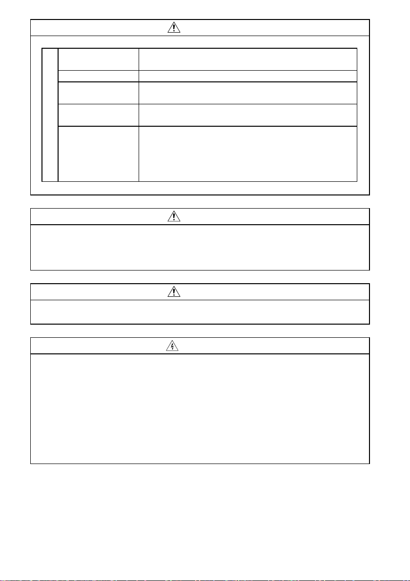
CAUTION
! Use the inverter under the following environmental conditions:
Ambient
temperature
Ambient humidity 90%RH or less (non-condensing)
Storage
temperature
Ambience
Environment
Altitude,
vibration
*Temperatures applicable for a short time, e.g. in transit.
(2) Wiring
-10°C to + 50°C (14°F to 122°F) (non-freezing)
-20°C to +65°C (-4°F to 149°F) *
Indoors (free from corrosive gas, flammable gas,
oil mist, dust and dirt)
Maximum 1000m (3280.80feet) above sea level
for standard operation. After that derate by 3% for
every extra 500m (1640.40feet) up to 2500m
(8202.00feet) (91%).
2
5.9m/s
or less (conforming to JIS C0911)
CAUTION
! Do not fit capacitive equipment such as power factor correction capacitor,
radio noise filter or surge suppressor to the output of the inverter.
! The connection orientation of the output cables U, V, W to the motor will
affect the direction of rotation of the motor.
(3) Trial run
CAUTION
! Check all parameters, and ensure that the machine will not be damaged by a
sudden start-up.
(4) Operation
WARNING
! When you have chosen the retry function, stay away from the equipment as it
will restart suddenly after an alarm stop.
! The [STOP] key is valid only when the appropriate function setting has been
made. Prepare an emergency stop switch separately.
! Make sure that the start signal is off before resetting the inverter alarm. A
failure to do so may restart the motor suddenly.
! The load used should be a three-phase induction motor only. Connection of
any other electrical equipment to the inverter output may damage the
equipment.
! Do not modify the equipment.
A - 3
CAUTION
! The electronic overcurrent protection does not guarantee protection of the
motor from overheating.
! Do not use a magnetic contactor on the inverter input for frequent
starting/stopping of the inverter.
! Use a noise filter to reduce the effect of electromagnetic interference.
Otherwise nearby electronic equipment may be affected.
! Take measures to suppress harmonics. Otherwise power harmonics from the
inverter may heat/damage the power capacitor and generator.
! When parameter clear or all clear is performed, each parameter returns to
the factory setting. Re-set the required parameters before starting operation.
! The inverter can be easily set for high-speed operation. Before changing its
setting, fully examine the performances of the motor and machine.
! In addition to the inverter's holding function, install a holding device to ensure
safety.
! Before running an inverter which had been stored for a long period, always
perform inspection and test operation.
(5) Emergency stop
CAUTION
! Provide a safety backup such as an emergency brake which will prevent the
machine and equipment from hazardous conditions if the inverter fails.
(6) Maintenance, inspection and parts replacement
CAUTION
! Do not carry out a megger (insulation resistance) test on the control circuit of
the inverter.
(7) Disposing of the inverter
CAUTION
! Treat as industrial waste.
(8) General instructions
Many of the diagrams and drawings in this instruction manual (basic) show the
inverter without a cover, or partially open. Never run the inverter in this status.
Always replace the cover and follow this instruction manual (basic) when
operating the inverter.
A - 4
Japanese Power Supply Harmonic Suppression Guideline
r
The "harmonic suppression guideline for household appliances and generalpurpose products" issued by the Ministry of International Trade and Industry in
September, 1994 applies to the FR-S500 series. By installing the FR-BEL or FRBAL power factor improving reactor, this product complies with the "harmonic
suppression techniques for transistorized inverters (input current 20A or less)"
established by the Japan Electrical Manufacturers' Association.
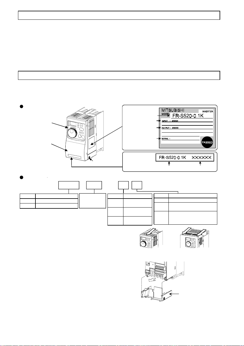
Product Checking and Parts Identification
Unpack the inverter and check the capacity plate on the front cover and the rating
plate on the inverter side face to ensure that the product agrees with your order
and the inverter is intact.
Part names and plates
Operation panel
Rating plate
Inverter type
Input rating
Output rating
Front cover
Wiring cover
Inverter type
FR - S520 -K -0.1
Symbol Voltage Class
Three-phase 200V class
S520
Single-phase 200V class
S520S
Represents
the inverter
capacity "kW ".
Removal and reinstallation of the front cover
Remove the front cover by pulling it toward
you in the direction of arrow.
To reinstall, match the cover to the inverter
front and i nsta ll it stra ight .
Removal and reinstallation of the wiring cover
The cover can be removed easily by pulling it
toward you.
To reinstall, fi t the cover to the invert er along
the guides.
Symbol Version
None
NA
EC
Serial number
Capacity plate
Inverter type
Symbol Protective Structure
Japanese
specification
North American
specification
European
specification
FR-S520(S)-0.1K to 0.75K FR-S520(S)-1.5K
None
R
C
Serial number
Standard structure
With RS-485 communication
function
Totally enclosed structure
IP40
Only for Japanese version
FR-S520-2.2K, 3.7K
Wiring cove
1
< Type with RS-485 communication function >
When using the RS-485 connector to wire the
cable, you can cut off the lug of the wiring cover
to wire it. (Cutting off the lug provides protective
Lug
structure IP10.)
CAUTION
The connector above the operation panel is for
manufacturer use. Do not touch it as doing so
may cause an electric shock.
1.
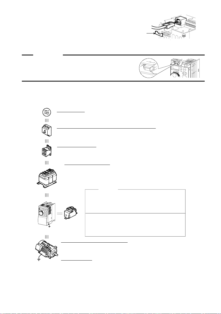
CONNECTION OF PERIPHERAL DEVICES
1.1 Basic Configuration
Power supply
Use within the permissible power supply specifications
(NFB)
or
(ELB)
(MC)
C reactor
(FR-BAL)
Earth (Ground)
Earth (Ground)
of the inverter. (Refer to page 40.)
No-fuse breaker or earth leakage circuit breaker
The breaker must be selected carefully since
an in-rush current flows in the inverter at power-on.
Magnetic contactor
Do not use this magnetic contactor to start and stop the
inverter. Doing so will cause the inverter life to be shorter.
Installation of reactors
The reactors must be used when the power factor is to be
improved or the inverter is installed near a large power supply
system (500kVA or more and wiring distance within 10m (32.81feet)).
Make selection carefully.
Inverter
The inverter life is influenced by ambient
temperature. The ambient temperature should
be as low as possible within the permissible
range. (Refer to page 42.)
Wrong wiring might lead to inverter dam age. The
DC reactor
(FR-BEL)
Devices connected to the output
Do not connect a power capacitor, surge suppressor
or radio noise filter to the output side.
Earth (Ground)
To prevent an electric shock, always ground the motor
and inverter.
For reduction o f in duction noise from the power line of the inverter,
it is recommend ed t o wire the ground cable by returnin g i t to t he
ground terminal of the inverter. (For details of noise reduction
techniques , refer to the instruc t ion manual (detailed).)
control signal lines must be kept fully away f r om
the main circuit to protect them from noise.
(Refer to page 5.)
2
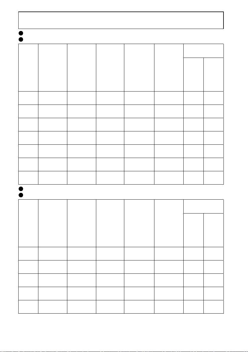
Selection of peripheral devices (Selection changes with the
power supply input specifications of the inverter.)
FR-S520-0.1K to 3.7K(-R)(-C)
FR-S520-0.1K to 3.7K-NA(R)
No-Fuse
Motor
Output
(kW
(HP))
0.1
(1/8)
0.2
(1/4)
0.4
(1/2)
0.75
(1)
1.5
(2)
2.2
(3)
3.7
(5)
Inverter
Type
FR-S520-
0.1K
FR-S520-
0.2K
FR-S520-
0.4K
FR-S520-
0.75K
FR-S520-
1.5K
FR-S520-
2.2K
FR-S520-
3.7K
Breaker
(NFB*1) or
Earth
Leakage
Circuit
Breaker
(ELB)
30AF/5AT
30AF/5AT
30AF/5AT
30AF/10AT
30AF/15AT
30AF/20AT
30AF/30AT
Power
Factor
Improving
AC
Reactor
FR-BAL-
0.4K (*3)
FR-BAL-
0.4K (*3)
FR-BAL-
0.4K
FR-BAL-
0.75K
FR-BAL-
1.5K
FR-BAL-
2.2K
FR-BAL-
3.7K
Power
Factor
Improving
DC
Reactor
FR-BEL-
0.4K (*3)
FR-BEL-
0.4K (*3)
FR-BEL-
0.4K
FR-BEL-
0.75K
FR-BEL-
1.5K
FR-BEL-
2.2K
FR-BEL-
3.7K
Magnetic
Contactor
(MC)
S-N10 2 2
S-N10 2 2
S-N10 2 2
S-N10 2 2
S-N10 2 2
S-N11,
S-N12
S-N20 3.5 3.5
FR-S520S-0.1K to 1.5K(-R)
FR-S520S-0.2K to 1.5K-EC(R)
No-Fuse
Motor
Output
(kW
(HP))
0.1
(1/8)
0.2
(1/4)
0.4
(1/2)
0.75
(1)
1.5
(2)
*1 Choose the NFB type to meet the power supply capacity.
*2 The size of the cabl e indicated assumes the wiring length of 20m (65.62feet).
*3 The power factor may be slightly lower.
Inverter
Type
FR-S520S-
0.1K
FR-S520S-
0.2K
FR-S520S-
0.4K
FR-S520S-
0.75K
FR-S520S-
1.5K
Breaker
(NFB*1) or
Earth
Leakage
Circuit
Breaker
(ELB)
30AF/5AT
30AF/10AT
30AF/10AT
30AF/15AT
30AF/20AT
Power
Factor
Improving
AC
Reactor
FR-BAL-
0.4K (*3)
FR-BAL-
0.4K (*3)
FR-BAL-
0.75K (*3)
FR-BAL-
1.5K (*3)
FR-BAL-
2.2K (*3)
Power
Factor
Improving
DC
Reactor
FR-BEL-
0.4K (*3)
FR-BEL-
0.4K (*3)
FR-BEL-
0.75K (*3)
FR-BEL-
1.5K (*3)
FR-BEL-
2.2K (*3)
Magnetic
Contactor
(MC)
S-N10 2 2
S-N10 2 2
S-N20 2 2
S-N20 2 2
S-N21 2 2
Cables (mm2)
R, S, T U, V, W
22
Cables (mm2)
R, S
1
, N>
<L
(*2)
(*2)
U, V, W
3
2.
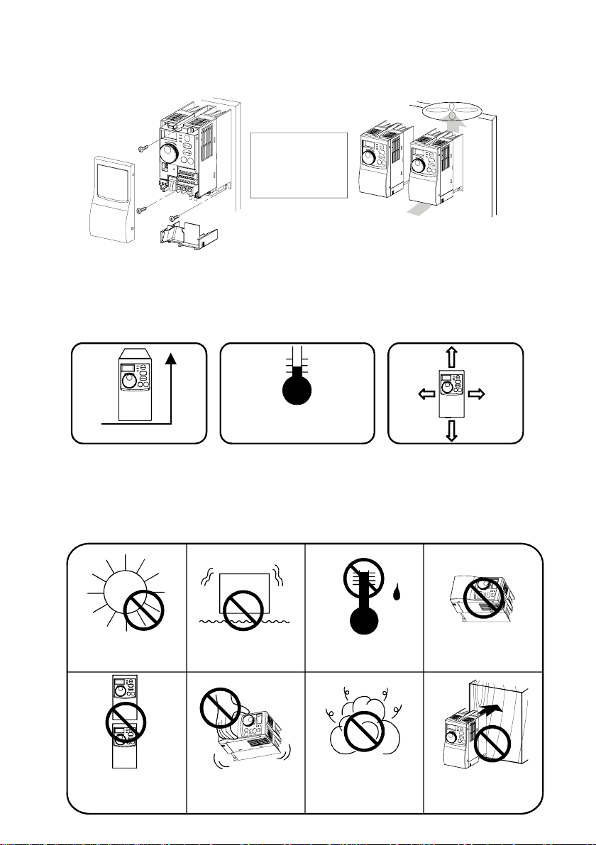
INSTALLATION METHOD
2.1 Installation of the Inverter
Enclosure surface mounting Mounting inside enclosure
Fix the front
cover and wiring
cover after
removing them.
When containing two or more
Leave enough clearances
and provide cooling measures.
• Install the inverter under the following conditions.
Ambient temperature
Vertical mounting
Vertical
and humidity
Temperature: -10°C to 50°C
(14°F to 122°F)
Humidity: 90%RH maximum
• The inverter consists of precision mechanical and electronic parts. Never install
or handle it in any of the following conditions as doing so could cause an
operation fault or failure.
inverters, install them in parallel
and provide cooling measures.
Enough clearances
10cm
1cm
(0.39inch)
or more
10cm
(3.94inch)
or more
These clearances are also necessary
for changing the cooling fan.
(1.5K or more)
(3.94inch)
or more
1cm
(0.39inch)
or more
Direct sunlight
Vertical mounting
(When mounted
inside enclosure)
Vibration
2
(5.9m/s or more)
Transportation by
holding front cover
or dial
High temperature,
high humidity
Oil mist, flammable
gas, corrosive gas,
fluff, dust, etc.
4
Horizontal placement
Mounting to
combustible
material
3.
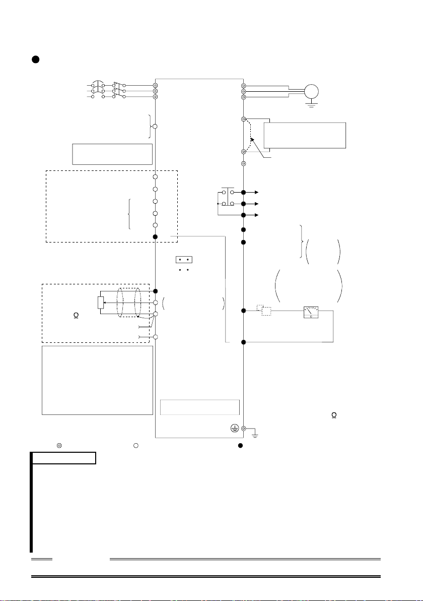
SPECIFICATIONS OF WIRING AND TERMINALS
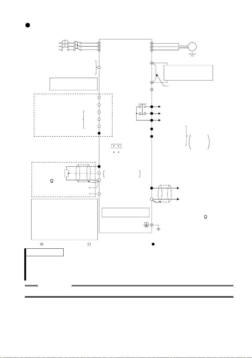
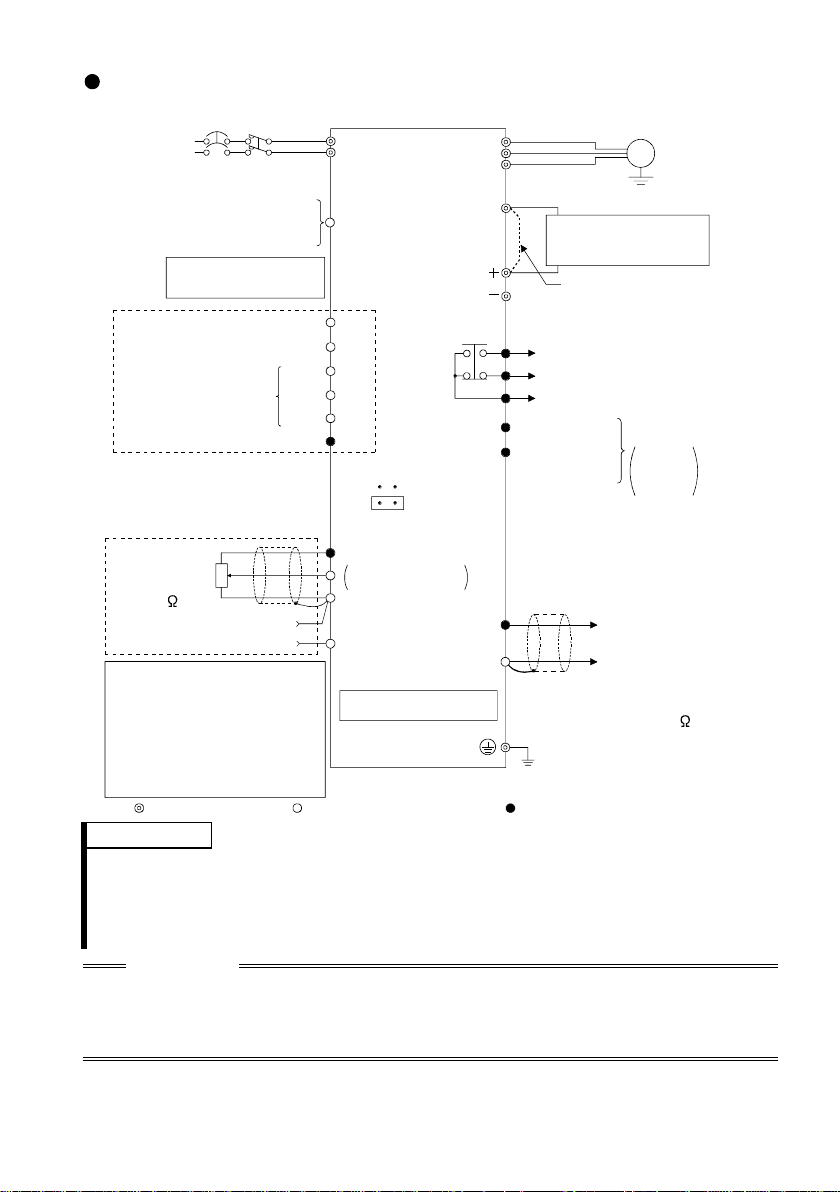
3.1 Terminal connection diagram (Japanese version)
FR-S520-0.1K to 3.7K (-R) (-C)
NFB
3-phase AC
power suppl y
External transistor common
Contact input common (source)
Frequency setting signals (Analog)
When using current input as the
frequency setting signal, set "4"
in any of Pr. 60 to Pr. 63 (input
terminal function selection) and
assign AU (current input selection)
to any of terminals RH, RM, RL
and STR.
24VDC power supply
Take care not to short
terminal s P C -SD.
Forward rotation start
Reverse rotation start
Multi-speed selection
Contact input common
Control input signals
(No voltage input allowed)
Frequency
setting
potentiometer
1/2W1k
(*4)
4 to 20mADC (+)
MC
3
2
1
Current input (-)
High
Middle
Low
Inverter
R
S
T
PC
STF
STR
RH
RM
RL
SD
SINK
(*3)
SOURCE
10 (+5V)
0 to 5VDC
2
0 to 10VDC
5 (Common)
4 (4 to 20mADC)
RS-485 Connector (*1)
Selected
U
V
W
P1
N
A
B
C
RUN
SE
FM
SD
Power factor improving
DC reactor
(FR-BEL: Option)
P
Alarm
output
Running
Open collector
output common
Calibration
resistor (*2)
Earth (Ground)
Grounding resistanc e 100 maximum
Grounding cable size: 2mm
Motor
IM
Ground
: Remove this
Jumper
jumper when FR-BEL
is connected.
Operation status
output
Open
collector
outputs
Indicator
1mA full-scale
Analog meter
(Digital indicator)
1mA
(+) (-)
2
Main circuit terminal, Control circuit input terminal,
Control circuit out put terminal
Remarks
*1 Only the type with RS-485 communication function
*2 Not needed when the setting dial is used for calibration. Used when
calibration must be made near the frequency meter for such a reason as a
remote frequency meter. However, the frequency meter needle may not
deflect to full-scale if the calibration resistor is connected. In this case, use
this resistor and setting dial together.
*3 You can switch between the sink and source logic positions. For details, refer
to the instruction manual (detailed).
*4 When the setting potentiometer is used frequently, use a 2W1kΩ potentiometer.
CAUTION
Keep the signal cables m ore th an 1 0cm (3.9 4inches) away from the power ca bles.
5
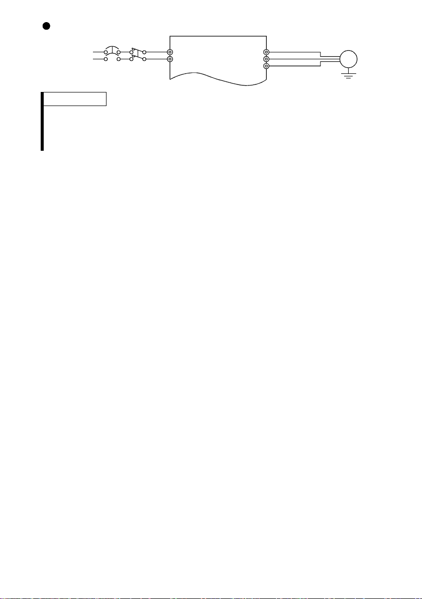
FR-S520S-0.1K to 1.5K (-R) (-C)
(
)
NFB
Power supply
MC
R
S
U
V
W
Motor
Remarks
• To ensure safety, connect the power input to the inverter via a magnetic
contactor and earth leakage circuit breaker or no-fuse breaker, and use the
magnetic contactor to switch power on-off.
• The output is three-phase 200V.
IM
Earth
Ground
6
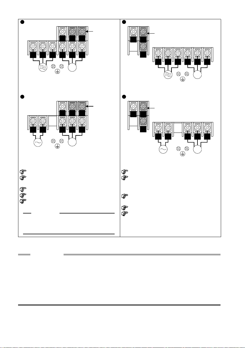
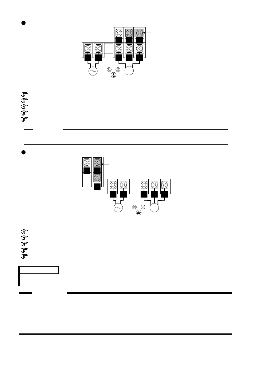
3.1.1 Layout and wiring of main circuit terminals
r
FR-S520-0.1K, 0.2K, 0.4K, 0.75K (-R) (-C) FR-S520-1.5K, 2.2K, 3.7K (-R) (-C)
RST
Jumper
P1
NP
NP
Jumper
RST
Power
supply
U V W
IM
Motor
P1
R S T
Power
supply
FR-S520S-0.1K, 0.2K, 0.4K, 0.75K (-R) FR-S520S-1.5K (-R)
RS
Power
supply
Jumpe
NP
P1
U V W
IM
Motor
NP
Jumper
P1
RS
Power
supply
Screw size: M3.5
Recommended cable size:
Crimping terminal : 2-3.5
Screw tightening torque: 1.2 N⋅m
Overall wiring lengt h:
2mm
2
(14 AWG)
100m (328.08feet) maximum *
CAUTION
If the wiring length of the 0.1K or 0.2K is
Screw size: M4
Recommended cable size:
Crimping terminal :
2
2mm
(14 AWG) (1.5K, 2.2K)
2
3.5mm
2-4 (1.5K, 2.2K), 5.5-4 (3.7K)
Screw tightening torque: 1.5N⋅m
Overall wiring lengt h:
100m (328.08feet)
30m (98.43feet) or more, reduce the
carrier frequency to 1kHz.
U V W
IM
Motor
U V W
IM
Motor
(12 AWG) (3.7K)
maximum *
* When automatic torque boost is selected i n Pr. 98 "automatic torque boost selection
(motor capacit y)": 30m (98.43feet) maximum.
CAUTION
The power supply cables must be connected to R, S, T. If they are connected
•
to U, V, W, the inverter will be damaged. (Phase sequence need not be
matched.)
(For use with a single-phase power supply, the power supply cables must be
connected to R and S.)
Connect the motor to U, V, W.
•
Turning on the forward rotation switch (signal) at this time rotates the motor
counterclockwise when viewed from the load shaft.
7
3.2 Terminal connection diagram (North America version)
FR-S520-0.1K to 3.7K-NA (R)
MC
3-phase AC
power supply
External transistor common
Contact input common (source)
Multi-speed selection
Control input signals
(No voltage input allowed)
Frequency setting signals (Analog)
Frequency
setting
potentiometer
1/2W1k
(*3)
When using current input as the
frequency setting signal, set "4"
in any of Pr. 60 to Pr. 63 (input
terminal function selection) and
assign AU (current input selection)
to any of terminals RH, RM, RL
and STR.
NFB
24VDC power supply
Take care not to short
terminals PC-SD.
Forward rotation start
Reverse rotation start
High
Middle
Low
Contact input common
3
2
1
Current input (-)
4 to 20mADC (+)
Main circuit terminal, Control circuit input terminal, Control circuit output terminal
Inverter
R
S
T
PC
STF
STR
RH
RM
RL
SD
SINK
(*2)
SOURCE
10 (+5V)
0 to 5VDC
2
0 to 10VDC
5 (Common)
4 (4 to 20mADC)
RS-485 Connector (*1)
Selected
U
V
W
P1
N
A
B
C
RUN
SE
AM
Power factor improving
DC reactor
(FR-BEL: Option)
P
Alarm
output
Running
Open collector
output common
5
Earth (Ground)
Grounding resistanc e 100 maximum
Grounding cable size: 2mm
Motor
IM
Earth
(Ground)
Jumper:
jumper when FR-BEL
is connected.
Remove this
Operation status
output
Open
collector
outputs
(+)
Analog signal
output
(0 to 5VDC)
(-)
2
Remarks
*1 Only the type with RS-485 communication function
*2 You can switch between the sink and source logic positions. For details, refer
to the instruction manual (detailed).
*3 When the setting potentiometer is used frequently, use a 2W1kΩ potentiometer.
CAUTION
Keep the signal cables m ore th an 1 0cm (3.9 4inches) away from the power ca bles.
8
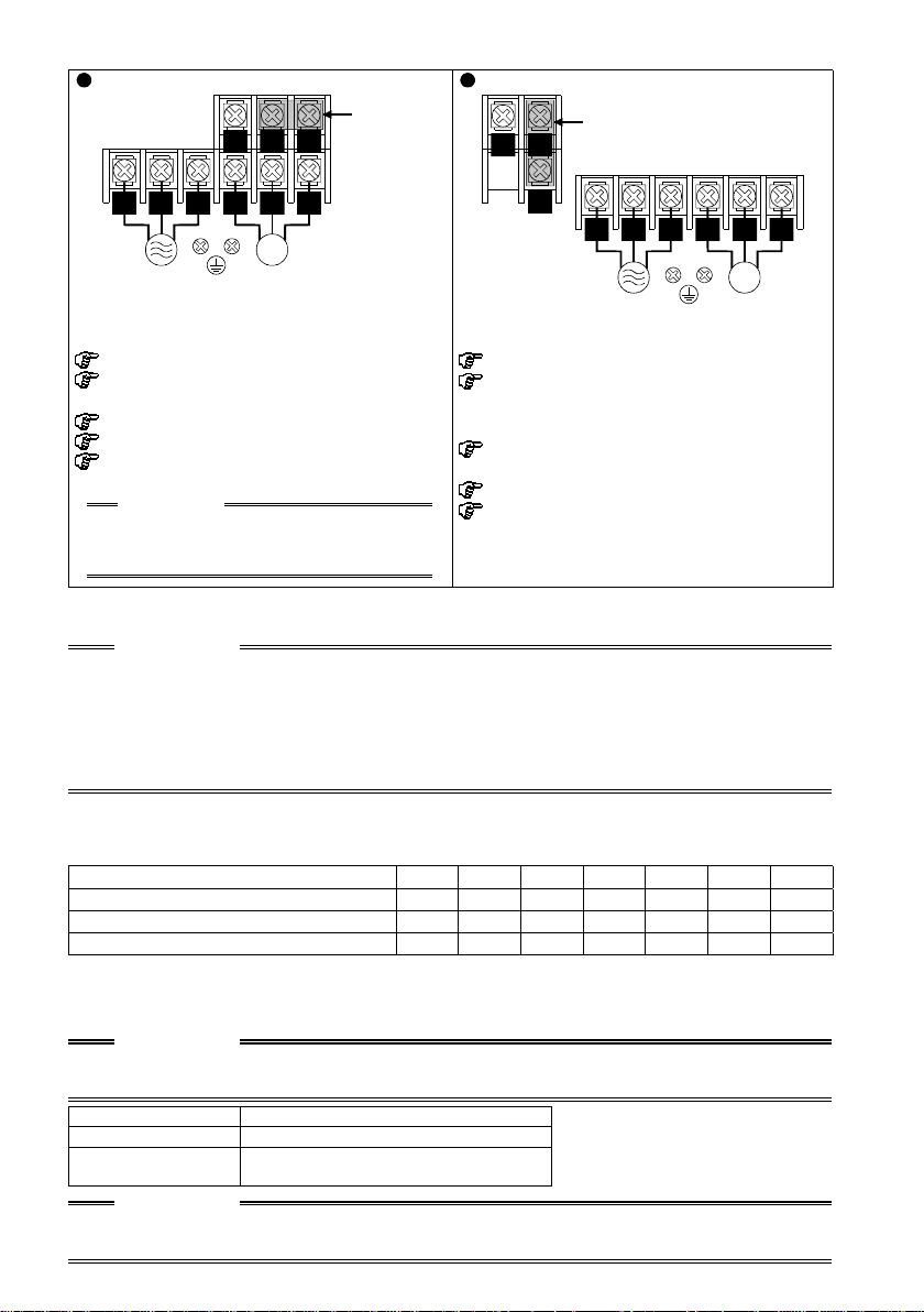
3.2.1 Layout and wiring of main circuit terminals
r
FR-S520-0.1K, 0.2K, 0.4K, 0.75K-NA (R) FR-S520-1.5K, 2. 2K, 3.7K-NA (R)
Jumpe
NP
P1
NP
Jumper
RST
Power
supply
Screw size: M3.5
Recommended cable size:
Crimping terminal : 2-3.5
Screw tightening torque: 1.2 N⋅m
Overall wiring lengt h:
CAUTION
If the wiring length of the 0.1K or 0.2K is
30m (98.43feet) or more, reduce the
carrier frequency to 1kHz.
* When automatic torque boost is selected i n Pr. 98 "automatic torque boost selection
(motor capacit y)": 30m (98.43feet) maximum.
U V W
IM
Motor
2
2mm
(14 AWG)
100m (328.08feet) maximum *
P1
R S T
Power
supply
Screw size: M4
Recommended cable size:
Crimping terminal :
Screw tightening torque: 1.5N⋅m
Overall wiring lengt h:
2
2mm
(14 AWG) (1.5K, 2.2K)
2
3.5mm
2-4 (1.5K, 2.2K), 5.5-4 (3.7K)
100m (328.08feet)
U V W
Motor
(12 AWG) (3.7K)
IM
maximum *
CAUTION
The power supply cables must be connected to R, S, T. If they are connected
•
to U, V, W, the inverter will be damaged. (Phase sequence need not be
matched.)
Connect the motor to U, V, W.
•
Turning on the forward rotation switch (signal) at this time rotates the motor
counterclockwise when viewed from the load shaft.
<When single-phase power input is provided for three-phase power input inverter
(NA version only)>
Reduce the output current.
•
FR-S520-"K-NA inverter 0.1 0.2 0.4 0.75 1.5 2.2 3.7
Rated output current (A) 0.4 0.8 1.5 2.5 4.0 5.0 7.0
Power supply capacity (kVA) 0.4 0.8 1.5 2.5 4.5 5.5 9.0
AC input power (kW ) 1.1 6.4 4.5 6.4 11.2 12.9 17.4
Set m9 (Pr. 637) "current detection filter".
•
Setting "801" in the manufacturer setting parameter C8 enables you to set the
m9 parameter.
CAUTION
Parameters other than m9 can also be made to be displayed, but never alter
these since they are manufacturer setting parameters.
m9 Setting Description
0 Single-phase pow er input
- - -
(Factory setting)
Three-phase power input
CAUTION
Always return the C8 parameter to 0 (factory setting) after you have finished the
setting of m9.
9
3.3 Terminal connection diagram (European version)
FR-S520S-0.2K to 1.5K-EC (R)
MC
NFB
Power supply
External transistor common
Contact input common (source)
Frequency setting signals (Analog)
24VDC power supply
Take care not to short
terminals PC-SD.
Forward rotation start
Reverse rotation start
High
Multi-speed selection
Contact input common
Control input signals
(No voltage input allowed)
Frequency
setting
potentiometer
1/2W1k
(*3)
When using current input as the
frequency setting signal, set "4"
in any of Pr. 60 to Pr. 63 (input
terminal function selection) and
assign AU (current input selection)
to any of terminals RH, RM, RL
and STR.
Main circuit terminal, Control circuit input terminal, Control circuit output terminal
3
1
Current input (-)
4 to 20mADC (+)
Middle
Low
2
Inverter
L
1
N
PC
STF
STR
RH
RM
RL
SD
SINK
(*2)
SOURCE
10 (+5V)
0 to 5VDC
2
0 to 10VDC
5 (Common)
4 (4 to 20mADC)
RS-485 Connector (*1)
Selected
U
V
W
P1
A
B
C
RUN
SE
AM
Power factor improving
DC reactor
(FR-BEL: Option)
Alarm
output
Running
Open collector
output common
5
Earth (Ground)
Grounding resistanc e 100 maximum
Grounding cable size: 2mm
Motor
IM
Earth
(Ground)
: Remove this
Jumper
jumper when FR-BEL
is connected.
Operation status
output
Open
collector
outputs
(+)
Analog signal
output
(-)
(0 to 5VDC)
2
Remarks
*1 Only the type with RS-485 communication function
*2 You can switch between the sink and source logic positions. For details, refer
to the instruction manual (detailed).
*3 When the setting potentiometer is used frequently, use a 2W1kΩ potentiometer.
• The output is three-phase 200V.
CAUTION
• Keep the signal cables more tha n 10cm (3.94inches) away from the power cables.
• To ensure safety, connect the power input to the inverter via a magnetic
contactor and earth leakage circuit breaker or no-fuse breaker, and use the
magnetic contactor to switch power on-off.
10
3.3.1 Layout and wiring of main circuit terminals
r
FR-S520S-0.2K, 0.4K, 0. 75K-EC (R)
Jumpe
P1
-
+
L1 N
Power
supply
Screw size: M3.5
Recommended cable size: 2mm
Crimping terminal : 2-3.5
Screw tightening torque: 1.2 N⋅m
Overall wiring length: 100m (328.08feet) maximum *
CAUTION
If the wiring length of the 0.2K is 30m (98.43fe et) or more, reduce the carrier frequency
to 1kHz.
FR-S520S-1.5K-EC (R)
+
-
P1
Screw size: M4
Recommended cable size:2mm
Crimping terminal : 2-4
Screw tightening torque: 1.5N⋅m
Overall wiring lengt h: 100m (328.08feet)
U V W
2
(14 AWG)
Jumper
L1 N
Power
supply
2
(14 AWG)
IM
Motor
maximum *
U V
Motor
W
IM
Remarks
* When automatic torque boost is selected in Pr. 98 "automatic torque boost
selection (motor capacity)": 30m (98.43feet) maximum.
CAUTION
For power input wiring, connect L1 to R/L1 of the terminal block and N to
•
S/L2 of the terminal block.
Connect the motor to U, V, W.
•
Turning on the forward rotation switch (signal) at this time rotates the motor
counterclockwise when viewed from the load shaft.
Do not connect the power supply to U, V and W.
•
11
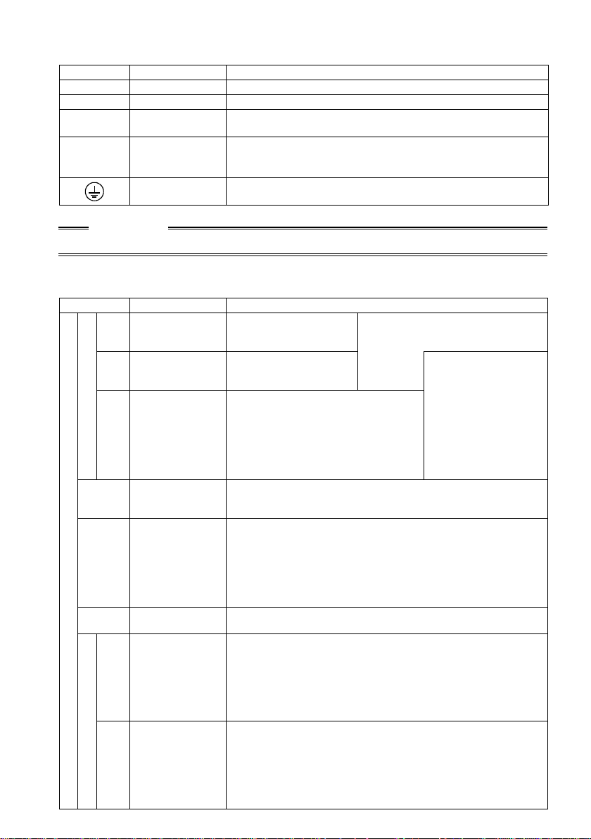
3.4 Main Circuit
3.4.1 Explanation of main circuit terminals
Symbol Terminal Name Description
R, S, T* AC power input Connect to the commercial power supply.
U, V, W Inverter output Connect a three-phase squirrel-cage motor.
N <->
P <+>, P1
* R, S, <L1, N> terminals for single-phase power input.
DC voltage
common
Power factor
improving DC
reactor connection
Earth (Ground)
CAUTION
< > Terminal names in parentheses are those of the EC version.
DC voltage common terminal. Not isolated from the power
supply and inverter output.
Remove the jumper from across terminals P <+> -P1 and
connect the optional power factor improving DC reactor (FRBEL).
For grounding the inverter chassis.
Must be earthed.
3.5 Control Circuit
3.5.1 Explanation of control circuit terminals
Symbol Terminal Name Description
Forward rotation
STF
start
Reverse rotation
STR
start
RH
Contact input
Multi-speed
RM
selection
RL
SD
Contact input
(*1)
common (sink)
External transistor
common
PC
24VDC power
supply
(*1)
Frequency setting
10
2
4
Contact input
common (source)
Frequency setting
power supply
Frequency
setting
(Voltage signal)
Frequency
setting
(Current signal)
Input signals
Turn on the STF signal
to start forward rotation
and turn it off t o stop.
Turn on the STF signal
to start reverse rotation
and turn it off t o stop.
You can select mult iple speeds by
shorting any of terminals RH, RM
and RL signal.
The priorities of the speed
commands are in order of jog,
multi-speed sett ing (RH, RM, RL,
REX) and AU.
Common terminal for contact inputs (terminal s STF, STR,
RH, RM, RL) and indicator connection (terminal FM).
Isolated from terminals 5 and SE.
When connecting t he transistor output (open collector
output) of a programma ble controller (PLC) etc., connect
the positive external power supply for transistor output to
this terminal to prevent a malfunction due to l eakage
current. It can be used as a 24V 0.1A DC power supply
across PC-SD termi nals. Acts as the common termi nal of
the contact input signals when source l ogic is selected.
5VDC, permissible l oad current 10mA.
Inputting 0 to 5VDC (0 to 10V) provides the maximum
output frequency at 5V (10V) and makes input and output
proportional.
Use Pr. 73 "0 to 5V, 0 to 10V selection" to switch between
5V and 10V.
Input resistance 10kΩ. Maximum permissible input voltage
20V.
Input 4 to 20mA DC. Factory-adjusted to be 0Hz at 4mA
and 60Hz <50Hz for EC version> at 20mA. Maximum
permissible input current 30mA. Input resistance
approximately. 250Ω.
Turn ON signal AU for current input.
Use any of Pr. 60 to Pr. 63 (input terminal function
selection) t o set the AU signal.
A stop command is given if STF
and STR signal turn ON at the
same time.
12
The terminal function
changes with the
setting of input
terminal function
selection (Pr. 60 to
Pr. 63). (*4)
 Loading...