

Mitsubishi FR-S520-0.1K, FR-S520-0.1K-R, FR-S540-0.1K, FR-S520-0.1K-C, FR-S540-0.1K-R Series Manual
...
2
●
As the default, the parameters that can be set have
been grouped into the minimum required twelve parameters. Thus, parameters can be managed easily.
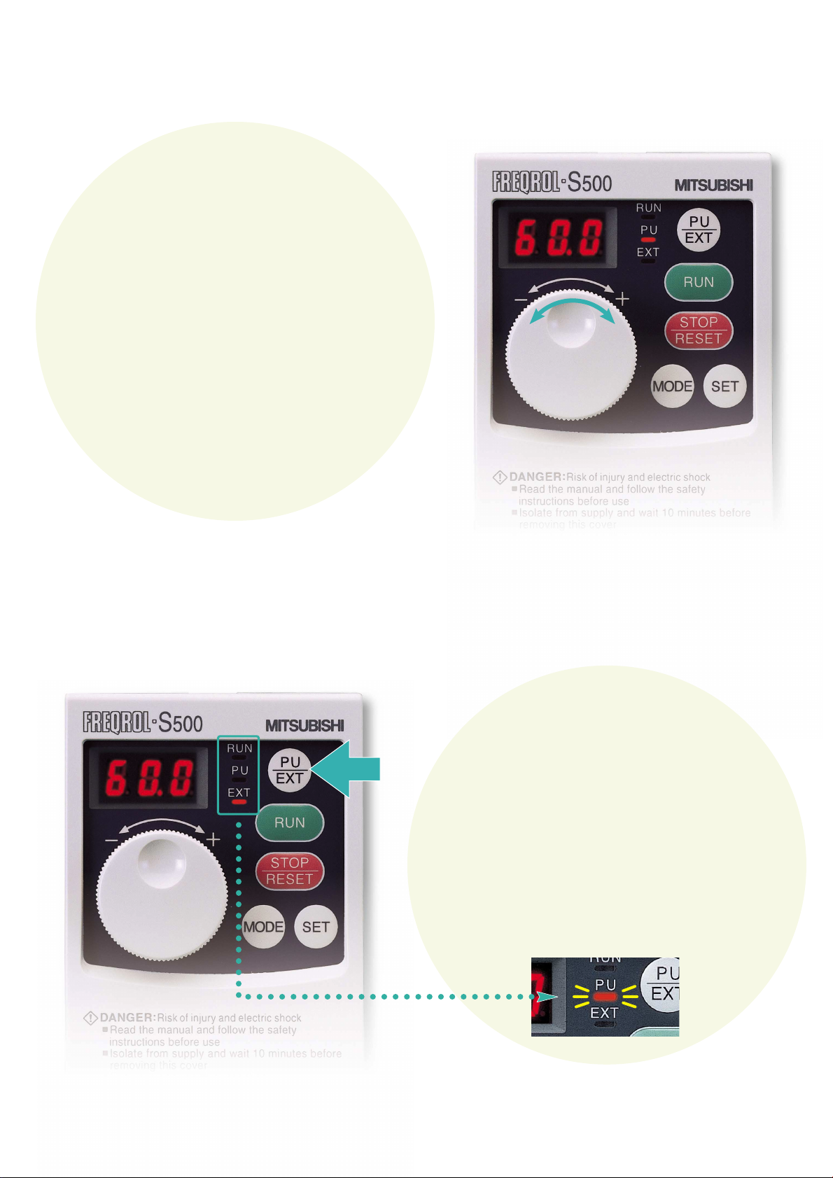
●
The modes can be changed between the PU and external operation modes just by pressing the PU/EXT (operation mode changeover) key. The current operation
mode can be confirmed with the status display LED.
●
The set frequency and the output current value can be
monitored just by using the setting dial (set frequency
monitor) or SET key (output current value monitor).
(When in the monitor display state.)
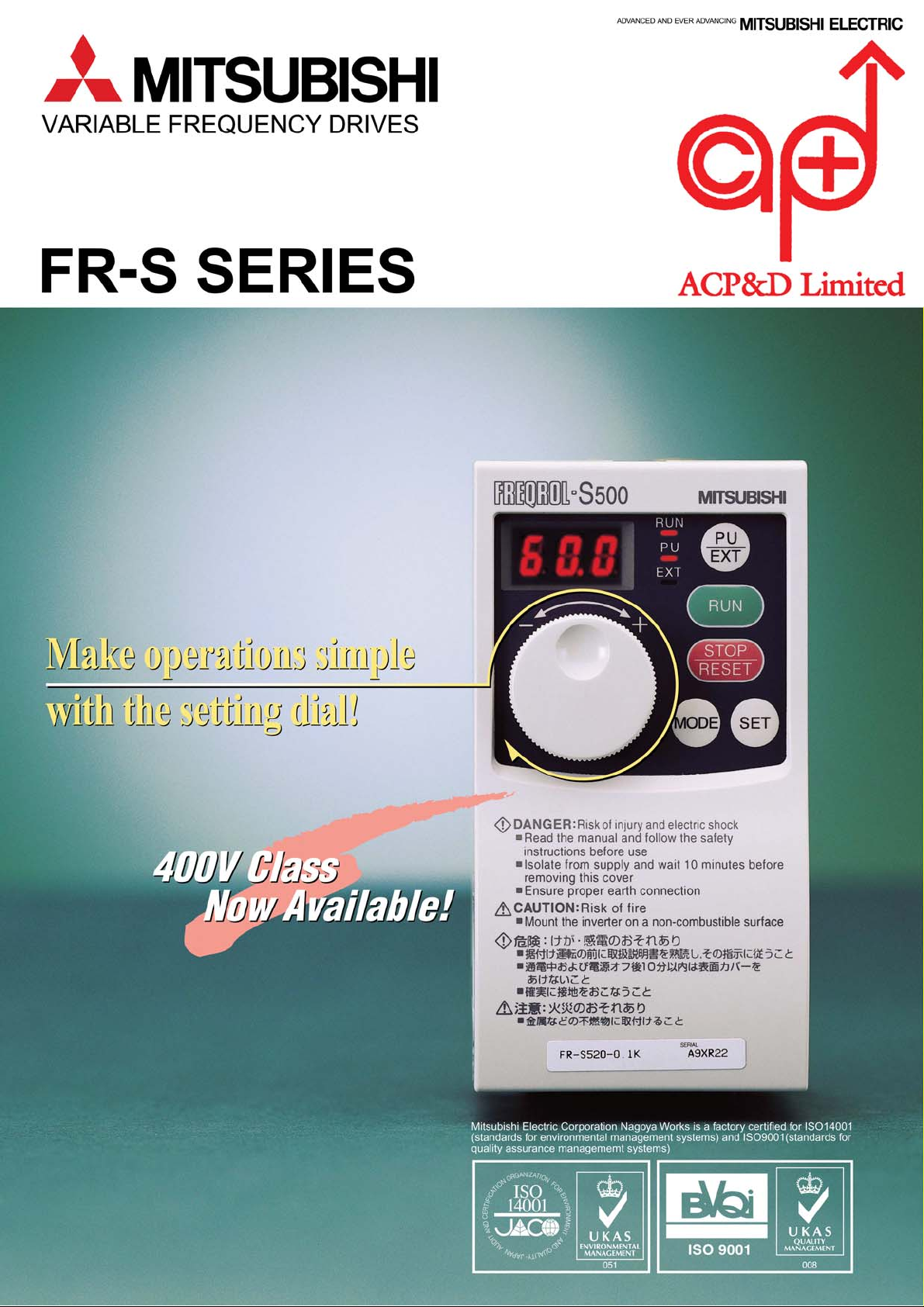
Simple Operation
1
●The frequency and parameters etc. can be set
with a few simple steps.
●Easily set values: turn quickly to greatly
change the value, and turn slowly to finely adjust the value.
●Accurate settings can be made with the new
notch-type "clicking" feel.
Quick Setting
using Setting Dial
The setting dial is
your new tool for operations
!!
See how easy it is to make simple operation settings.
PUSH
Example of PU operation mode
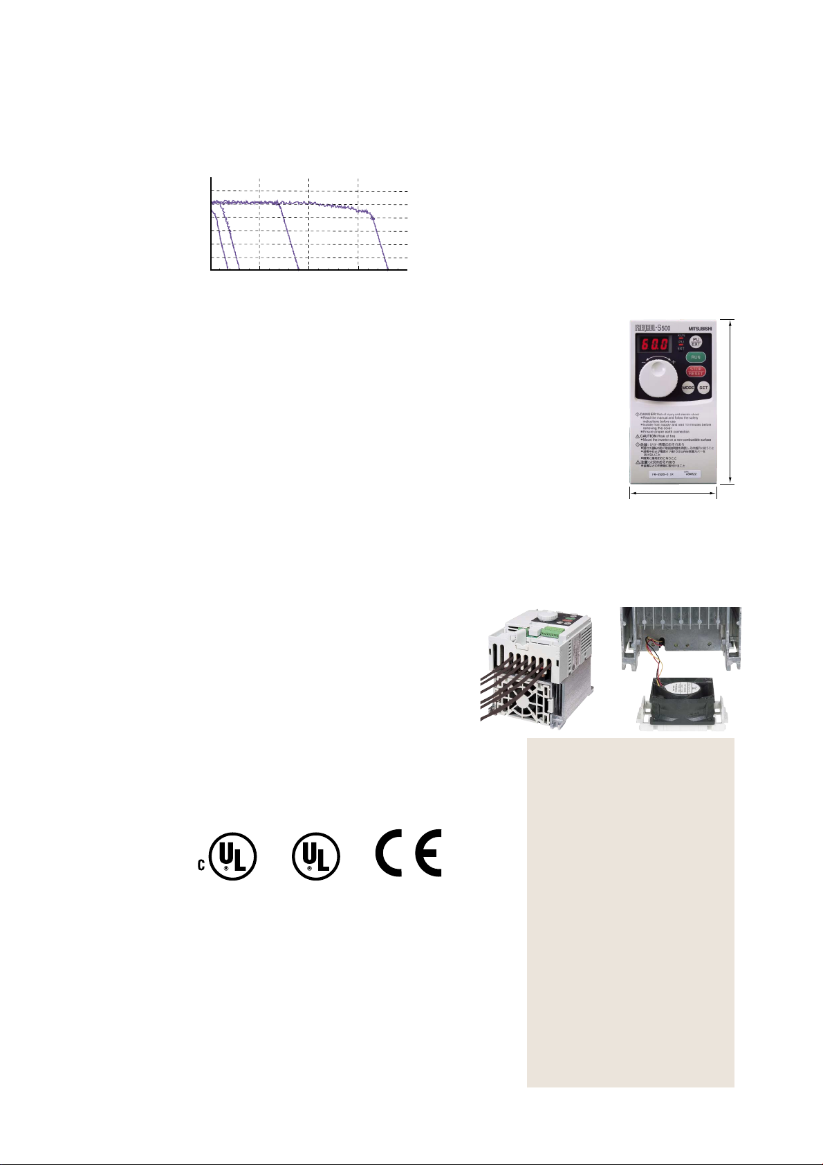
●By incorporating Mitsubishi's original and newly
developed "automatic torque boost control", a maximum 150% torque at 6Hz is possible.
●The need for torque boost setting can be eliminated
and the current during no load can be controlled.
Example speed-torque characteristics using newly
developed automatic torque boost control is shown
on the left.
(For SF-JR 4P 0.75kW motor)
3
Automatic Torque Boost Control
●The foot print is the same as the Mitsubishi FREQROL-E520.
●(400V class installation area has been unified to 108mm(128m.)
●The height dimensions for all capacities have been unified to 128mm,
making panel layout easier.
4
Compact Design
●The popular Soft-PWM control is incorporated as standard.
An increase in noise can be reduced, and noise can be suppressed to a minimum.
●Reactor connection to aid harmonic suppression.
The compact and lightweight DC reactor (FR-BEL) can be connected.
Connect an AC reactor (FR-BAL) when using the single-phase 100V class.
5
Environment Awareness
●The cooling fan can be replaced easily due to a
simple cassette design. By setting the fan "ONOFF control", operation with an extended life
can be realized. (The ON-OFF control is set as
the default.)
●Wiring space is secured and the wiring work ef-
ficiency is enhanced by incorporating an expanded front cover and comb-type wiring cover.
6
Easy Maintenance
●Compatible with UL, cUL and EN (CE Mark).
7
Global specification
●Terminal function (multi-speed 15 of speeds, error
reset, output stop, etc.) can be selected
●In-rush current suppression circuit is standard for
all capacities
●PID control
●4 to 20mA input
●Sink/Source logic is selectable
8
Other Handy Functions
68mm
128mm
300180 900 1800
300
200
100
0
Rotation speed(r/min)
CONTENTS
Load torque( )
Control panel
…………………………………
2
Model Configuration
…………………………………
3
General Specifications
…………………………………
4
Common Specifications
…………………………………
4
Extermal Dimension Drawings
…………………………………
5
Terminal connection diagram
…………………………………
5
Explanation of Terminals
…………………………………
5
List of Parameters
…………………………………
6
Explanation of Parameters
…………………………………
7
Alarm Displays
…………………………………
8
Selecting Peripheral Devices
…………………………………
8
List of Options
…………………………………
8
Precautions
…………………………………
9
1
%
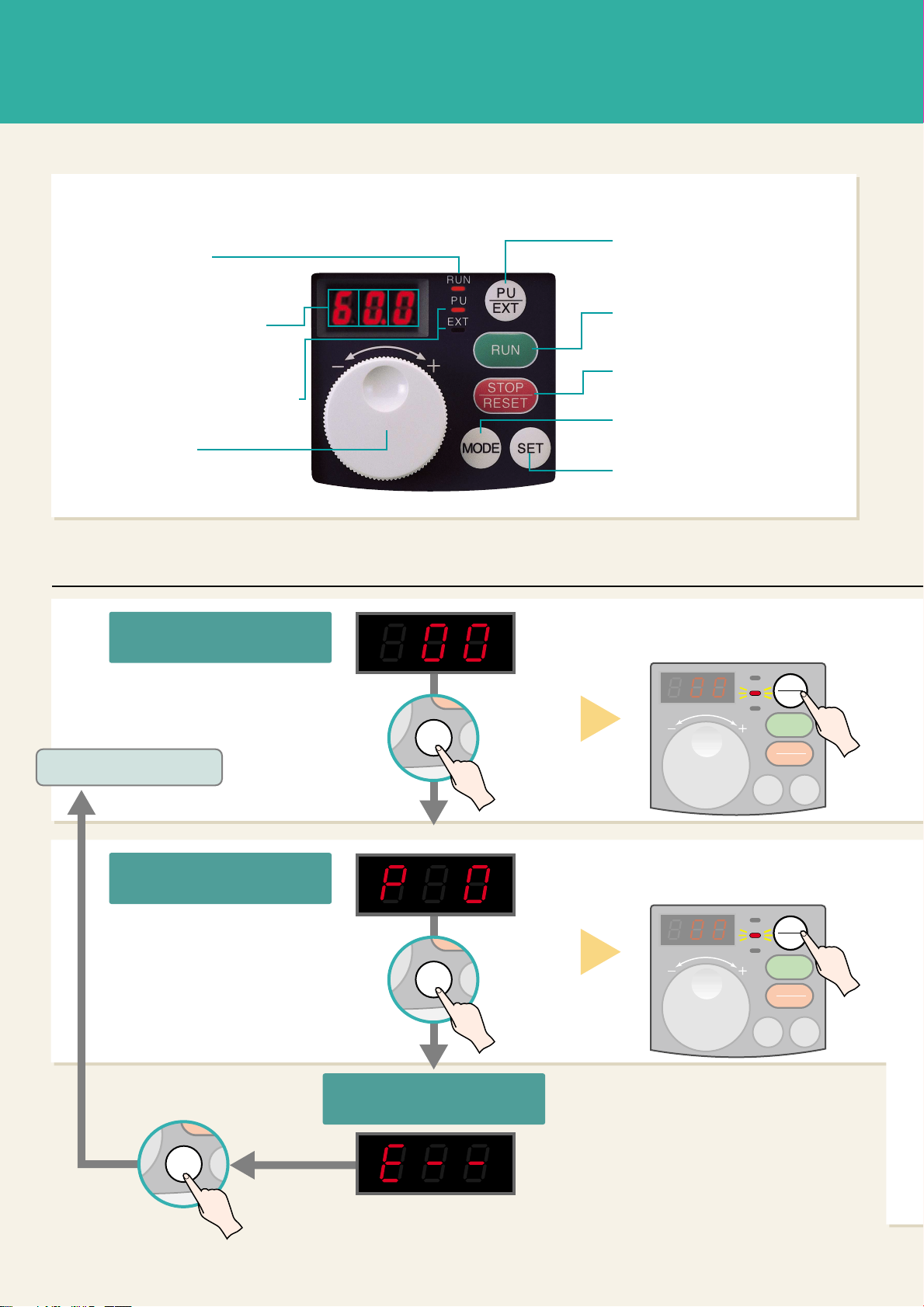
PU/EXT key:
RUN key:
Forward run
STOP/RESET key:
MODE key:
SET key:
PU display/EXT display
Setting dial
3-digit LED monitor
RUN display
Changes the operation mode.
PU=
Control panel operation mode
EXT=External operation mode
(Can be changed to reverse run
with parameter settings.)
Stop/reset (at alarm)
Changes the setting mode.
Sets the frequency setting and
parameter setting.
Shows the operation state.
Shows the parameter number
and setting value.
Shows operation mode.
Sets the frequency, and
changes the parameter setting.
Basic operations (At default setting)
RU
PU
EX
RU
PU
EX
RU
PU
EX
SET
RESET
SET
SET
MOD
MOD
MOD
PU
EXT
RUN
RUN
PU
EXT
MODE
SET
STOP
RESET
PU
EXT
RUN
RUN
PU
EXT
MODE
SET
STOP
RESET
MODE
SE
RESET
MODE
SE
RESET
MODE
SE
RESET
Press the PU/EXT key to display PU.
[Example] Operating with
the control panel
Press the PU/EXT key to display PU.
[Example] Changing
the parameter setting
If the parameters are set in the external operation mode (When only EXT
is lit), Er2 (error) may appear depending on the parameter.
Monitor and
frequency setting
Parameter setting
Alarm history
Press the MODE key.
(Screen at power ON)
This screen appears.
Press the MODE key.
Press the MODE key.
Return to the monitor and
frequency setting.
Note:
2 3
 Loading...