


FRONT
SUSPENSION
33A-1
CONTENTS
GENERAL INFORMATION 2..................
SERVICE SPECIFICATIONS 2.................
SPECIAL TOOLS 3..........................
ON-VEHICLE SERVICE 4.....................
Wheel Alignment Check and Adjustment 4.......
Ball Joint Dust Cover Check 5..................
33109000094
STRUT ASSEMBLY 6........................
LOWER ARM ASSEMBLY 10................
STABILIZER BAR 14........................
33A-2
FRONT SUSPENSION -
General Information/Service Specifications
GENERAL INFORMATION
33100010089
The front suspension is a McPherson strut with coil spring. The shock absorber is hydraulic double-acting
type.
COIL SPRING
Items SPACE RUNNER SPACE WAGON - 2WD SPACE WAGON - 4WD
Wire diameter´average diameter
´
free length mm
13.6´160´368 14.0´160´371 14.1´160´381
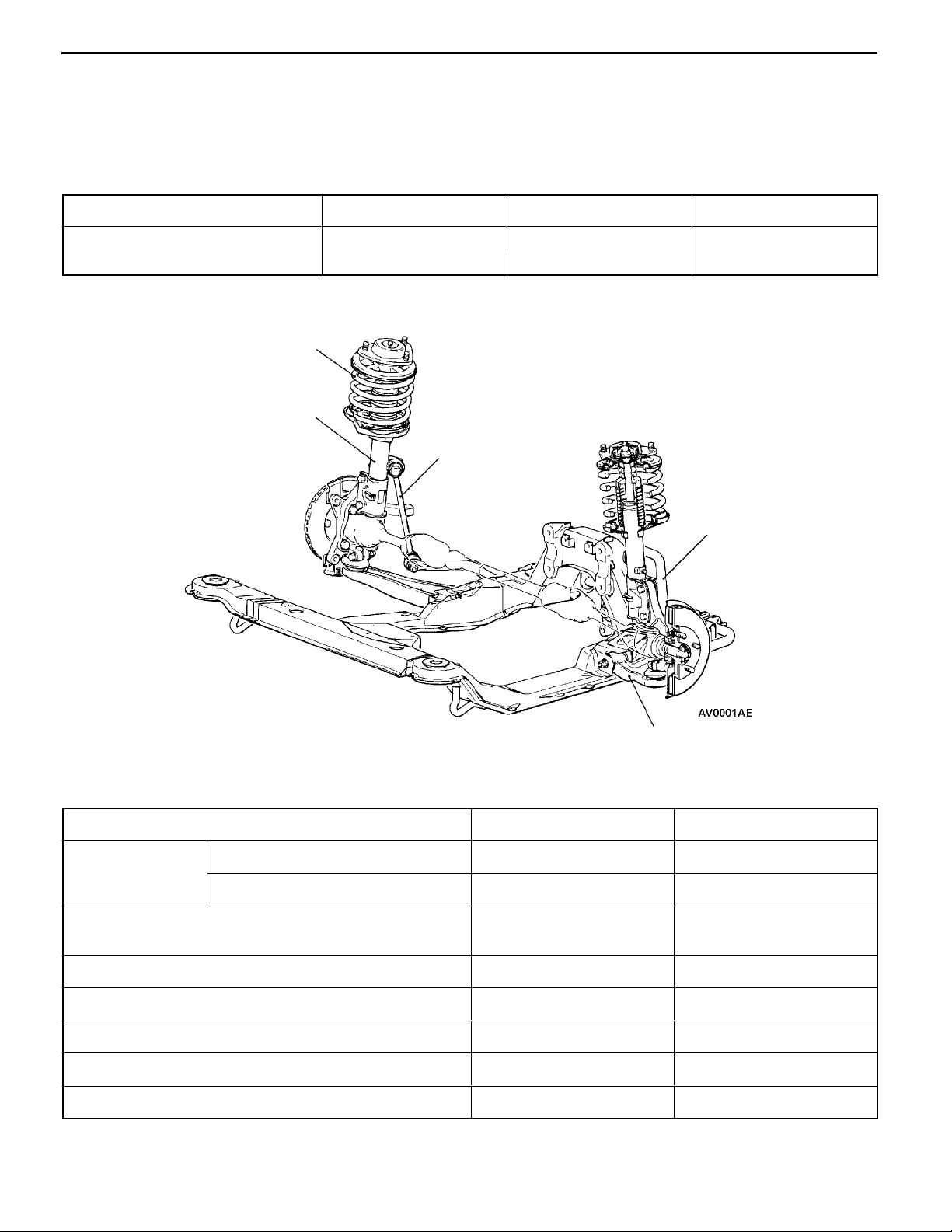
CONSTRUCTION DIAGRAM
Coil spring
Strut assembly
Stabilizer link
Stabilizer bar
Lower arm assembly
SERVICE SPECIFICATIONS
Items SPACE RUNNER SPACE WAGON
Toe-in At the centre of tyre tread mm 0±3 0±3
Toe-angle (per wheel) 0_00’±08’ 0_00’±08’
Toe-out angle on turns
(inner wheel when outer wheel at 20_)
Camber 0_00’±30’ * -0_10’±30’ *
Caster 2_45’±30’ * 2_50’±30’ *
Kingpin inclination 11_27’ 12_49’
Lower arm ball joint rotation starting torque Nm 2.0 - 8.8 2.0 - 8.8
Stabilizer link ball joint turning torque Nm 1.7 - 3.1 1.7 - 3.1
NOTE
*: difference between right and left wheel: less than 30’
22_10’ 21_50’
33100030115
FRONT SUSPENSION -
Special Tools
33A-3
SPECIAL TOOLS
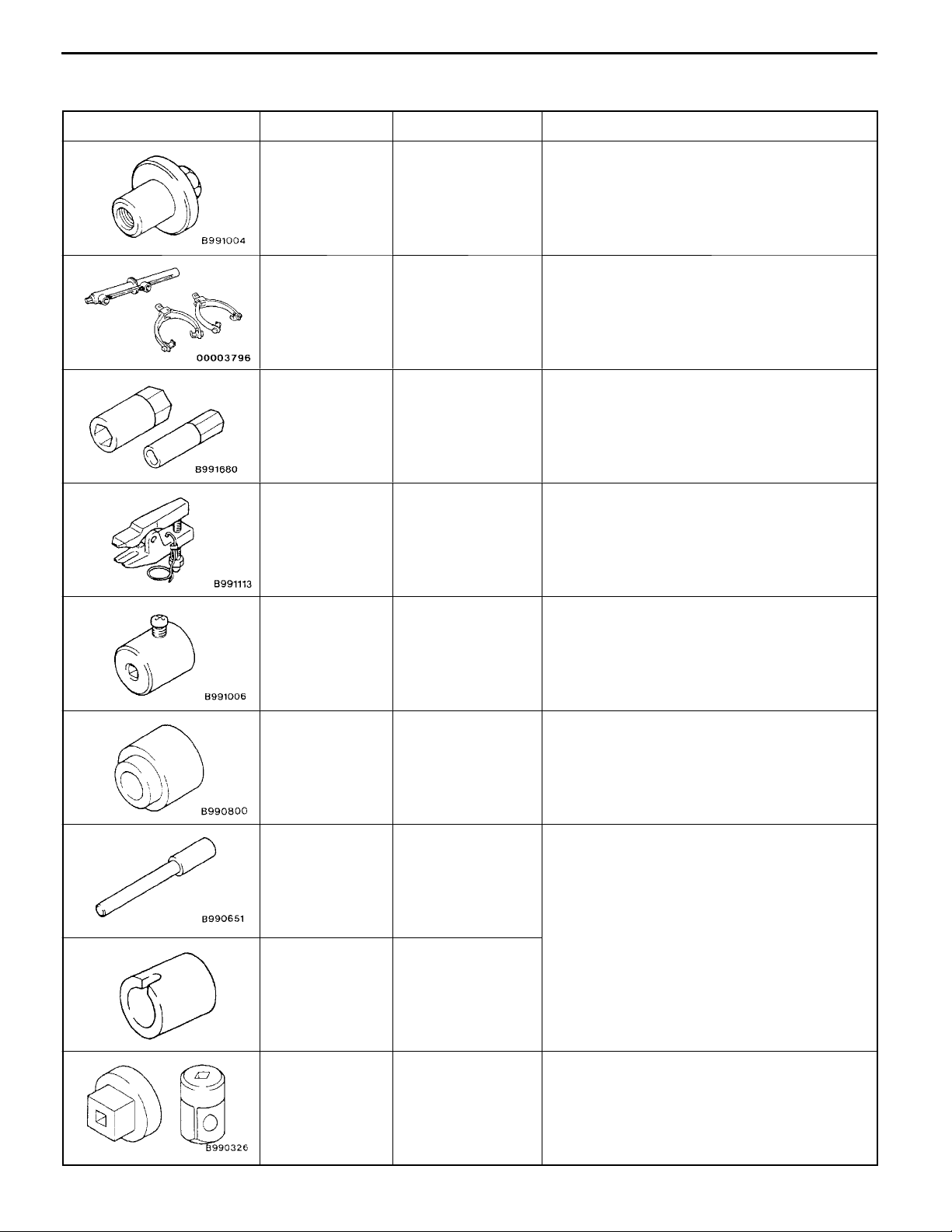
Tools Number Name Use
MB991004 Wheel alignment
gauge attachment
A: MB991237
B: MB991238
A
B
A
A: MB991619
B: MB991682
B
MB991406,
MB990635 or
MB991113
A: Spring compres-
sor body
B: Arm set
A: Wrench
B: Socket
Steering linkage
puller
33100060077
Wheel alignment measurement
<Vehicles with aluminium type wheelsd
Coil spring compression
Strut assembly disassembly and reassembly
Tie rod end disconnection
MB991006 Preload socket Lower arm ball joint rotation starting torque
measurement
MB990800 Ball joint remover
and installer
MB990651 Bar Driving out and press-fitting of lower arm
MB998716 Crankshaft wrench
Lower arm ball joint dust cover installation
bushing
MB990326 Preload socket Stabilizer link ball joint turning torque measure-
ment
33A-4
Tools UseNameNumber
FRONT SUSPENSION -
Special Tools/On-vehicle Service
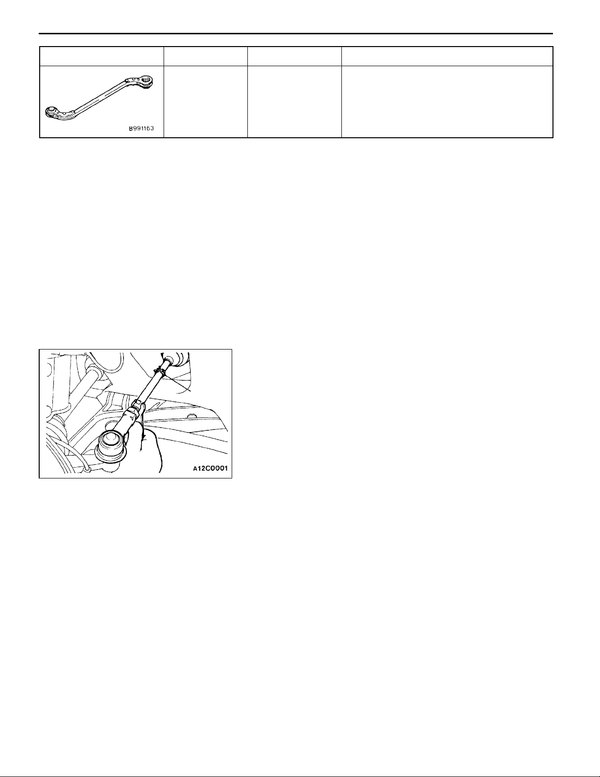
MB991 164 Door adjusting
wrench
ON-VEHICLE SERVICE
WHEEL ALIGNMENT CHECK AND
ADJUSTMENT
Measure the wheel alignment with the vehicle parked on a
level surface.
The front suspension, steering system, and wheels should
be serviced to normal condition prior to measurement of wheel
alignment.
TOE-IN
Standard value:
At the centre of tyre tread 0±3mm
Toe angle (per wheel) 0_00’±08’
Clip
1. If the toe-in is not within t h e standard value, adjust the
toe-in by undoing the clip and turning the left and right
tie rod turnbuckles by the same amount (in opposite
directions).
Stabilizer bar bracket mounting bolt removal
and installation
33100090267
NOTE
The toe will move out as the left turnbuckle is turned
toward the front of the vehicle and the right turnbuckle
is turned toward the rear of the vehicle.
2. Use a turning radius gauge to check that the steering
angle is at the standard value.
(Refer to GROUP37A - On-vehicle Service.)
TOE-OUT ANGLE ON TURNS
To check the steering linkage, especially after the vehicle
has been involved in an accident or if an accident is presumed,
it is advisable to check the toe-out angle on turns in addition
to the wheel alignment.
Conduct this test on the left turn as well as on the right turn.
Standard value (inner wheel when outer wheel
at 20_):
<SPACE RUNNER> 22_10’
<SPACE WAGON> 21_50’
FRONT SUSPENSION -
CAMBER, CASTER AND KINGPIN INCLINATION
On-vehicle Service
33A-5
MB991004
Standard value:
Item SPACE
RUNNER
Camber (difference between right
and left wheel: less than 30’)
Caster (difference between right
and left wheel: less than 30’)
Kingpin inclination 11_ 27’ 12_ 49’
0_00’ ± 30’ -0_10’ ± 30’
2_45’ ± 30’ 2_50’ ± 30’
SPACE
WAGON
NOTE
1. Camber and caster are preset at the factory and cannot
be adjusted.
2. If camber is no t within the standard value, check and
replace bent or damaged parts.
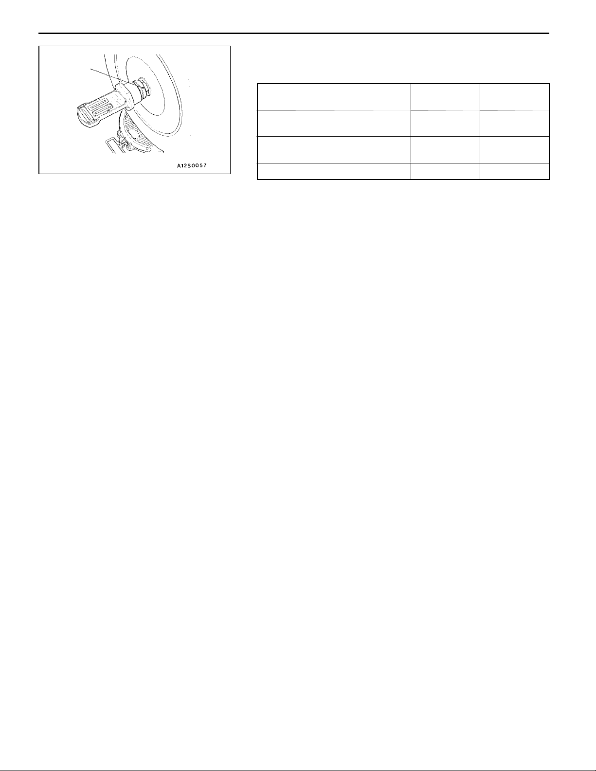
3. For vehicles with aluminium type wheels, attach the
camber/caster/kingpin gauge to the drive shaft by using
the special tool. Tighten the special tool to the same
torque 196 - 255 Nm as the drive shaft nut.
Caution
To prevent the wheel bearing from damage, never
subject the wheel bearings to the vehicle load when
the drive shaft nuts are loosened.
BALL JOINT DUST COVER CHECK
33200860090
1. Check the dust cover for cracks or damage by pushing
it with finger.
2. If the dust cover is cracked or damaged, replace the
upper arm assembly, compression lower arm assembly,
lateral lower arm assembly or stabilizer link.
NOTE
Cracks or damage of the dust cover may cause damage
of the ball joint.

33A-6
FRONT SUSPENSION -
Strut Assembly
STRUT ASSEMBLY
REMOVAL AND INSTALLATION
Pre-removal Operation
Injector Driver Removal (Refer to GROUP 13.)
44 Nm
33200110126
Post-installation Operation
D Injector Driver Installation (Refer to GROUP 13.)
D Check the Dust Cover for Cracks or Damage by
Pushing it with Finger.
D Wheel Alignment Check and Adjustment
(Refer to P.33A-4.)
5
6
3
1
4
Removal steps
1. Brake hose bracket
2. Front wheel speed sensor harness
<Vehicles with ABS>
3. Stabilizer link connection
INSPECTION
D
D
39 Nm
2
106 Nm
4. Knuckle connection
5. Strut mounting nut
6. Strut assembly
33200120020
Check for oil leaks from the strut assembly.
Check the strut assembly for damage or deformation

FRONT SUSPENSION -
Strut Assembly
33A-7
DISASSEMBLY AND REASSEMBLY
8
9
10
33200130139
69 - 78 Nm
2
1
3
4
5
6
7
Disassembly steps
AA""AA 1. Self-locking nut
2. Washer
3. Strut insulator assembly
4. Bearing
5. Upper spring seat
6. Upper spring pad
7. Bump rubber
8. Coil spring
9. Spring tube
10. Strut assembly

33A-8
FRONT SUSPENSION -
Strut Assembly
MB991237
MB991682
MB991238
MB991619
DISASSEMBLY SERVICE POINT
AA"
1. Use the special tools to compress the coil spring.
2. Use the special tools to remove the self-locking nut.
SELF-LOCKING NUT REMOVAL
Caution
(1) To compress the coil spring sufficiently, install
the special tools evenly,and so that the maximum
lengthwill beattainedwithintheinstallation range.
(2) To prevent the special tool from damage, do not
use an impact wrench to tighten the special tool
bolt.
Caution
Do not use an impact wrench as internal parts of
the strut assembly will be loosened.
Pipe
REASSEMBLY SERVICE POINT
"AA
1. Check that the bearing is properly assembled.
2. With the coil spring held compressed by the special tools
3. Line up the holes in the strut assembly lower spring seat
4. Correctly align both ends of the coil spring with the grooves
SELF-LOCKING NUT INSTALLATION
(MB991237 and MB991238), provisionally tighten the selflocking nut.
Caution
To prevent the special tool from damage, do not use
an impact wrench to tighten the special tool bolt.
with the hole in the upper spring seat.
NOTE
The job is easily accomplished with a pipe.
in the spring seat, and then loosen the special tools
(MB991237 and MB991238).

MB991682
FRONT SUSPENSION -
5. Using the special tool, tighten the self-locking nut to the
specified torque.
Specified torque: 69 - 78 Nm
Strut Assembly
33A-9
MB991619
Caution
Do not use an impact wrench as internal parts of
the strut assembly will be loosened.
INSPECTION
D Check the bearing for wear or rust.
D Check the rubber parts for damage or deterioration.
D Check the spring for deformation, deterioration or damage.
D Check the shock absorber for deformation.
33200140064

33A-10
FRONT SUSPENSION -
Lower Arm Assembly
LOWER ARM ASSEMBLY
33200160121
REMOVAL AND INSTALLATION
Caution
*: To prevent bushings from breakage”the parts indicated by * should be temporarily tightened,
and then fully tightened with the vehicle on the ground in the unladen condition.
Post-installation Operation
D Check the Dust Cover for Cracks or Damage by
Pushing it with Finger.
D Wheel Alignment Check and Adjustment
(Refer to P.33A-4.)
6
5
88 - 108 Nm
39 Nm
2
1
88 - 108 Nm*
AA"
AB"
5
3
177 Nm
Removal steps
1. Tie rod end connection
2. Stabilizer link connection
3. Stay
4. Lower arm and knuckle connection
6
78 Nm
AC"
"AA
24 - 33 Nm
98 - 118 Nm
4
5. Lower arm and front member
connection
6. Lower arm assembly

Ball joint
Nut
MB991406,
MB990635 or
MB991113
FRONT SUSPENSION -
REMOVAL SERVICE POINTS
Cord
AA"
Caution
1. Loosen the nut of the special tool, but do not remove
2. Tie the special tool with a cord not to let it fall off.
TIE ROD END DISCONNECTION
it.Ifit isremoved, theballjoint threadwill be damaged.
Lower Arm Assembly
33A-11
Front member
Front member
mounting bolts
Stay
AB"
STAY REMOVAL
The stay is tightened together with the front member. After
the stay is removed, tighten the bolts loosely to hold the
front member.
NOTE
If the lower arm assembly has been removed, tighten the
bolts loosely to hold the front member.
AC"
LOWER ARM AND FRONT MEMBER
DISCONNECTION
To remove the connection bolts of the lower arm at the vehicle
rear side, remove the front member mounting bolts, and then
lower the front member.
Knuckle
A
Lower arm
assembly
INSTALLATION SERVICE POINT
"AA
1. Install the lower arm assembly to the knuckle.
2. If grease has flown out of the dust cover by pushing
3. Check that there is no clearance between the knuckle
LOWER ARM ASSEMBLY INSTALLATION
Caution
When installing the lower arm assembly, make sure
that the ball joint stud (A) does not protrude 4 mm
or more from the knuckle in order to prevent grease
from flowing out.
the lower arm in the knuckle excessively, replace the
dust cover. (Refer to P.33A-12.)
and the dust cover.

33A-12
FRONT SUSPENSION -
Lower Arm Assembly
MB991006
INSPECTION
33200170117
D Check the bushing for wear and deterioration.
D Check the lower arm for bend or breakage.
D Check the stay for deterioration or damage.
D Check all bolts for condition and straightness.
LOWER ARM BALL JOINT ROTATION STARTING
TORQUE CHECK
1. After shaking the ball joint stud several times, install the
nut to the stud and use the special tool to measure the
rotation starting torque of the ball joint.
Standard value: 2.0 - 8.8 Nm
2. When the measured value exceeds the standard values,
replace the lower arm assembly.
3. When the measured value is lower than the standard
value, check that the ball joint turns smoothly without
excessive play. If so, it is possible to use that ball joint.
MB990800
Dust cover
Snap ring
LOWER ARM BALL JOINT DUST COVER CHECK
1. Check the dust cover for cracks or damage by pushing
it with finger.
2. If the dust cover is cracked or damaged, replace the
lower arm assembly.
NOTE
Cracks or damage of the dust cover may cause damage
of the ball joint. When it is damaged during service work,
replace the dust cover.
LOWER ARM BALL JOINT DUST COVER
REPLACEMENT
Only when the dust cover is damaged accidentally during
service work, replace the dust cover as follows:
1. Remove the dust cover.
2. Apply multipurpose grease to the lip and inside of the
dust cover.
3. Using the special tool, press the dust cover until it contacts
the snap ring.
4. Check the dust cover for cracks or damage by pushing
it with finger.
33200820098

FRONT SUSPENSION -
Lower Arm Assembly
33A-13
Bushing
Lower arm
assembly
MB990651
MD998716
Piece
of
metal
MB990651
MD998716
BUSHING REPLACEMENT
33200810118
Replace the rear bushing by the following procedure.
1. Use the special tools to drive out the bushing.
2. Use the special tools to presss in the bushing.
3. Position the bushing so that its hollow part is as shown.
4. Press in the bushing until its outer tube top surface is
lined up with the lower arm assembly.
Lower arm
assembly
Bushing
Hollow
part
Lower arm assembly
Outer
tube
Piece
of
metal
60
_

33A-14
FRONT SUSPENSION -
Stabilizer Bar
STABILIZER BAR
REMOVAL AND INSTALLATION
Post-installation Operation
Check the Dust Cover for Cracks or Damage by Pushing
it with Finger.
4
33200190137
39 Nm
2
3
39 Nm
"AA
"AA
"AA
Front side of
vehicle
Approx. 20 mm
39 Nm
Removal steps
1. Stabilizer link
D
Front member (Refer to GROUP 32.)
2. Stabilizer bar bracket
3. Bushing*
4. Stabilizer bar
Bushing
1
NOTE
*: If only the bushing is removed and installed, refer to
P.33A-15.
INSTALLATION SERVICE POINT
"AA
1. Position the bushing so that its cut is aligned as shown.
2. Position the stabilizer at the left side of the vehicle so
STABILIZER BAR/BUSHING/STABILIZER BAR
BRACKET INSTALLATION
that its identification mark is as shown, and then tighten
the stabilizer bar bracket mounting bolts.

FRONT SUSPENSION -
Stabilizer Bar
33A-15
MB990326
INSPECTION
332000200076
D Check the bushing for wear and deterioration.
D Check the stabilizer bar for deterioration or damage.
D Check all bolts for condition and straightness.
STABILIZER LINK BALL JOINT TURNING TORQUE
CHECK
1. After shaking the ball joint stud several times, install the
nut to the stud and use the special tool to measure the
turning torque of the ball joint.
Standard value: 1.7 - 3.1 Nm
2. When the measured value exceeds the standard value,
replace the stabilizer link.
3. When the measured value is lower than the standard
value, check that the ball joint turns smoothly without
excessive play. If so, it is possible to use that ball joint.
Front member mounting bolts
Side cover
mounting clip
STABILIZER LINK BALL JOINT DUST COVER CHECK
1. Check the dust cover for cracks or damage by pushing
it with finger.
2. If the dust cover is cracked or damaged, replace the
stabilizer link.
NOTE
Cracks or damage of the dust cover may cause damage
of the ball joint. When it is damaged during service work,
replace the dust cover.
BUSHING REPLACEMENT
33201010012
1. Remove the side cover mounting clip.
2. Remove the front member mounting bolt and stay.
Stay

33A-16
Bushing
Stabilizer bar bracket
FRONT SUSPENSION -
3.Use the special tool to remove the stabilizer bar bracket
mounting bolt.
4. Remove the stabilizer bar bracket.
MB991164
Stabilizer Bar
Front side of
the vehicle
Approx. 20 mm
Clip ring
Bushing
5. Position a new bushing so that its cut is as shown.
6. Position the stabilizer at the left side of the vehicle so
that its identification mark is as shown, and then tighten
the stabilizer bar bracket mounting bolts.
7. Install the stay, front member, side cover mounting clip
in that order.
STABILIZER LINK BALL JOINT DUST COVER
REPLACEMENT
Only when the dust cover is damaged accidentally during
service work, replace the dust cover as follows:
1. Remove the clip ring and the dust cover.
2. Apply multipurpose grease to the inside of the dust cover.
3. Use plastic tape on the stabilizer link threads as shown
in the illustration, and then install the dust cover to the
stabilizer link.
4. Secure the dust cover by the clip ring.
5. Check the dust cover for cracks or damage by pushing
it with finger.
33201020015
 Loading...