

Mitsubishi Electric Fresh Master GUF-50RD3, Fresh Master GUF-50RDH3, Fresh Master GUF-100RDH3, Fresh Master GUF-100RD3 Installation Instructions Manual

ENGLISH
Fresh Master
Models:
GUF-50RDH3 • GUF-50RD3
GUF-100RDH3
•
GUF-100RD3
Installation Instructions
(For use by dealer/contractor)
For use with the R410A&R407C&R22
• Please take the time to read through these instructions before commencing with the installation work.
They will help to install the Fresh Master properly and
safely.
• The separate Operating Instructions are for the user.
Make sure that they are handed over to the customer.
The warranty will not apply to damage resulting
from failure to follow the warnings and precautions set forth in the
Installation Instructions
.
GUF-50RDH3 shown above.
Humidifier function not available on GUF-50RD3 and
GUF-100RD3.
Contents
1. Safety precautions ............................................ 2-4
2. Accessories .......................................................... 5
3. Outline drawings .................................................. 5
4. Selecting an installation site ................................. 6
5. Installing the Fresh Master ................................6-7
6. Supply pipe and drain pipe work .......................... 8
7. Refrigerant pipe work ...................................... 9-11
8. Electrical wiring .............................................12-16
9. Feature settings ............................................ 17-19
10. Test run ......................................................... 19-20
11. Troubleshooting ................................................. 21
2
ENGLISH
1. Safety precautions
3 ) Remote controller
Warning:
The Remote controller should be installed in such a way that children cannot play with it.
4) Drain hose
Caution:
Make sure that the drain hose is installed so that drainage can go
ahead smoothly. Incorrect installation may result in water leakage, causing damage to furniture.
5 ) Power Supply, fuse or circuit breaker
Warning:
•
Make sure that the unit is powered by a dedicated power supply.
Other appliances connected to the same power supply could
cause an overload.
• Make sure that there is a mains power switch.
• Be sure to adhere to the unit’s voltage and fuse circuit breaker
ratings. Never use a cable or a fuse with a higher rating than
the one specified.
6 ) Grounding
Caution:
• The unit must be properly grounded. Never connect the
grounding wire to a gas pipe, water pipe, lightning conductor
or telephone grounding wire. If the unit is not grounded properly, electric shock may result.
• Check frequently that the ground wire from the outdoor unit is
properly connected to both the unit’s ground terminal and the
grounding electrode.
ss
ss
s Before operating the unit, make sure you read
all the “Safety precautions”.
ss
ss
s “Safety precautions” lists important points about
safety. Please be sure to follow them.
Symbols used in the text
Warning:
Describes precautions that should be observed to avoid the risk
of injury or death to the user.
Caution:
Describes precautions that should be observed to prevent damage to the unit.
Symbols used in the illustrations
: Indicates that important instructions must be followed.
: Indicates a part which must be grounded.
: Beware of electric shock. (This symbol is displayed on the main
unit label.) <Colour: Yellow>
Warning:
Carefully read the labels affixed to the main unit.
1.1. Installation
ss
ss
s After you have read this manual, keep it and the Installation
Manual in a safe place for easy reference whenever a question
arises. If the unit is going to be operated by another person,
make sure that this manual is given to him or her.
Warning:
• The unit should not be installed by the user. Ask the dealer or
an authorized company to install the unit. If the unit is installed
improperly, water leakage, electric shock or fire may result.
• Use only accessories authorized by Mitsubishi Electric and
ask your dealer or an authorized company to install them. If
accessories are installed improperly, water leakage, electric
shock or fire may result.
• The Installation Manual details the suggested installation
method. Any structural alteration necessary for installation
must comply with local building code requirements.
• Never repair the unit or transfer it to another site by yourself.
If repair is performed improperly, water leakage, electric shock
or fire may result. If you need to have the unit repaired or
moved, consult your dealer.
1 ) Outdoor unit
Warning:
• The outdoor unit must be installed on a stable, level surface,
in a place where there is no accumulation of snow, leaves or
rubbish.
• Do not stand on, or place any items on the unit. You may fall
down or the item may fall, causing injury.
Caution:
The outdoor unit should be installed in a location where air and
noise emitted by the unit will not disturb the neighbours.
2) Fresh Master
Warning:
The Fresh Master should be securely installed. If the unit is loosely
mounted, it may fall, causing injury.
3
ENGLISH
1.2. Precautions for devices that use
R407C refrigerant
Caution:
• Do not use the existing refrigerant piping.
- The old refrigerant and refrigerator oil in the existing piping contains a large amount of chlorine which may cause the refrigerator
oil of the new unit to deteriorate.
• Use refrigerant piping made of C1220 (CU-DHP) phosphorus
deoxidized copper as specified in the JIS H3300 “Copper and
copper alloy seamless pipes and tubes”. In addition, be sure
that the inner and outer surfaces of the pipes are clean and
free of hazardous sulphur, oxides, dust/dirt, shaving particles,
oils, moisture, or any other contaminant.
- Contaminants on the inside of the refrigerant piping may cause
the refrigerant residual oil to deteriorate.
• Store the piping to be used during installation indoors and
keep both ends of the piping sealed until just before brazing.
(Store elbows and other joints in a plastic bag.)
- If dust, dirt, or water enters the refrigerant cycle, deterioration of
the oil and compressor trouble may result.
• Use ester oil, ether oil or alkylbenzene (small amount) same
as the refrigerator oil to coat flares and flange connections.
- The refrigerator oil will degrade if it is mixed with a large amount
of mineral oil.
• Use liquid refrigerant to fill the system.
-
If gas refrigerant is used to seal the system, the composition of the
refrigerant in the cylinder will change and performance may drop.
• Do not use a refrigerant other than R407C.
- If another refrigerant (R22, etc.) is used, the chlorine in the refrig-
erant may cause the refrigerator oil to deteriorate.
• Use a vacuum pump with a reverse flow check valve.
- The vacuum pump oil may flow back into the refrigerant cycle
and cause the refrigerator oil to deteriorate.
• Do not use the following tools that are used with conventional
refrigerants.
(Gauge manifold, charge hose, gas leak detector, reverse flow
check valve, refrigerant charge base, vacuum gauge, refrigerant recovery equipment)
- If the conventional refrigerant and refrigerator oil are mixed in the
R407C, the refrigerant may deteriorate.
-
If water is mixed in the R407C, the refrigerator oil may deteriorate.
- Since R407C does not contain any chlorine, gas leak detectors
for conventional refrigerants will not react to it.
• Do not use a charging cylinder.
-
Using a charging cylinder may cause the refrigerant to deteriorate.
• Be especially careful when managing the tools.
- If dust, dirt, or water gets in the refrigerant cycle, the refrigerant
may deteriorate.
1.3. Precautions for devices that use
R410A refrigerant
• Make sure to use new refrigerant piping.
- When using the existing piping which used R22, take care of the
following points.
• Replace the flare nut with that is attached to the product. Flare
section must be finished with the flare processing. (See P.10.)
• Use of piping with thin wall should be avoided. (See P.10.)
• Use refrigerant piping made of C1220 (CU-DHP) phosphorus
deoxidized copper as specified in the JIS H3300 “Copper and
copper alloy seamless pipes and tubes”. The pipes must have
the wall thickness as shown in the table below. In addition, be
sure that the inner and outer surfaces of the pipes are clean
and free of hazardous sulphur, oxides, dust/dirt, shaving
particles, oils, moisture, or any other contaminant.
It is strictly prohibited to use pipes with thin wall not listed in
the above table.
If the inside of pipe is contaminated, it could cause deterioration of
refrigerator oil, or other problems.
• Store the piping to be used during installation indoors and
keep both ends of the piping sealed until just before brazing.
(Store elbows and other joints in a plastic bag.)
- If dust, dirt, or water enters the refrigerant cycle, deterioration of
the oil and compressor trouble may result.
• Use ester oil, ether oil or alkylbenzene (small amount) same
as the refrigerator oil to coat flares and flange connections.
- The refrigerator oil will degrade if it is mixed with a large amount
of mineral oil.
• Do not use a refrigerant other than R410A.
- If another refrigerant (R22, etc.) is used, the chlorine in the refrigerant
may cause the refrigerator oil to deteriorate.
• Use a vacuum pump with a reverse flow check valve.
- The vacuum pump oil may flow back into the refrigerant cycle
and cause the refrigerator oil to deteriorate.
• For the following tools, use only the tools special to the
refrigerant R410A.
- Tools as listed in the following table are required for the refrigerant
R410A.
• Be especially careful when managing the tools.
- If dust, dirt, or water gets in the refrigerant cycle, the refrigerant
may deteriorate.
• Do not use a charging cylinder.
-
Using a charging cylinder may cause the refrigerant to deteriorate.
1.4. Before conducting supply pipe
and drain pipe work
[Supply pipe work is not required for GUF-50 • 100RD3]
Caution:
• The water quality of the permeable film humidifier's supply
water should meet public waterworks standards, and have a
hardness less than 100 mg/
RR
RR
R. If the supply water does not
meet these standards, use a deionizer.
• The supply pressure must be within the range of 2×10⁴pa to
49×104pa.
-
Supply pressure that is lower than the specified range will cause the
water to not supplied the permeable-film humiditier, and the humidifier may not work. Supply pressure that exceeds the specified range
may cause damage to the solenoid valve and result in water leaks.
• Drain pipe gradient must be more than 1/100.
- Drain water will not be properly discharged.
• For areas that are extremely cold in winter, perform freezeprevention on the supply pipe by wrapping a freeze prevention heater and thermal insulation.
- Cold temperatures may freeze water, and damage supply pipe.
• Install the drain piping according to this installation Manual
to ensure proper drainage. Wrap thermal insulation around
the pipes to prevent condensation.
- Improper drain piping may cause water leakage and damage to
furniture and other possessions.
ø6.35, Wall thickness 0.8 mm
ø12.7, Wall thickness 0.8 mm
ø9.52, Wall thickness 0.8 mm
ø15.88, Wall thickness 1.0 mm
Gauge manifold
Charging hose
Gas leak detector
Torque wrench
Tool name (For R410A)
Flare tool
Protrusion adjust copper pipe gauge
Vacuum pump adaptor
Balance for refrigerant charging

4
ENGLISH
1.5. Before getting installed
Caution:
• Do not install the unit where combustible gas may leak.
- If the gas leaks and accumulates around the unit, an explosion
may result.
• Do not use the Fresh Master where food, pets, plants, precision instruments, or artwork are kept.
- The quality of the food, etc. may deteriorate.
• Do not use the Fresh Master in special environments.
- Oil, steam, sulfuric smoke, etc. can significantly reduce the per-
formance of the Fresh Master or damage its parts.
• When installing the unit in a hospital, communication station,
or similar place, provide sufficient protection against noise.
-
The inverter equipment, private power generator, high-frequency
medical equipment, or radio communication equipment may cause
the Fresh Master to operate erroneously, or fail to operate. On the
other hand, the Fresh Master may affect such equipment by creating noise that disturbs medical treatment or image broadcasting.
• Do not install the unit on a structure that may cause leakage.
- When the room humidity exceeds 80% or when the drain pipe is
clogged, condensation may drip from the Fresh Master. Perform
collective drainage work together with the outdoor unit, as required.
1.6. Before getting installed (moved) -
electrical work
Caution:
• Ground the unit.
- Do not connect the ground wire to gas or water pipes, lightning
rods, or telephone ground lines. Improper grounding may result
in electric shock.
•
Install the power cable so that tension is not applied to the cable.
- Tension may cause the cable to break and generate heat and
cause a fire.
• Install an leak circuit breaker, as required.
- If an leak circuit breaker is not installed, electric shock may re-
sult.
• Use power line cables of sufficient current carrying capacity
and rating.
-
Cables that are too small may leak, generate heat, and cause a fire.
• Use only a circuit breaker and fuse of the specified capacity.
- A fuse or circuit breaker of a larger capacity or a steel or copper
wire may result in a general unit failure or fire.
• Do not wash the Fresh Master.
- Washing them may cause an electric shock.
•
Be careful that the installation base is not damaged by long use.
- If the damage is left uncorrected, the unit may fall and cause
personal injury or property damage.
• Be very careful about product transportation.
- Only one person should not carry the product if it weighs more
than 20 kg.
- Fresh Master use PP bands for packaging. Do not use any PP
bands for a means of transportation. It is dangerous.
- Do not touch the heat exchanger fins. Doing so may cut your
fingers.
- When transporting the outdoor unit, suspend it at the specified
positions on the unit base. Also support the outdoor unit at four
points so that it cannot slip sideways.
• Safely dispose of the packing materials.
- Packing materials, such as nails and other metal or wooden parts,
may cause stabs or other injuries.
- Tear apart and throw away plastic packaging bags so that chil-
dren can not play with them. If children play with a plastic bag
which was not torn apart, they face the risk of suffocation.
1.7. Before starting the test run
Caution:
• Turn on the power at least 12 hours before starting operation.
- Starting operation immediately after turning on the main power
switch can result in severe damage to internal parts. Keep the
power switch turned on during the operational season.
• Do not touch the switches with wet fingers.
- Touching a switch with wet fingers can cause electrification.
• Do not touch the refrigerant pipes during and immediately after operation.
- During and immediately after operation, the refrigerant pipes are
may be hot or cold, depending on the condition of the refrigerant
flowing through the refrigerant piping, compressor, and other refrigerant cycle parts. Your hands may suffer burns or frostbite if
you touch the refrigerant pipes.
• Do not operate the Fresh Master and outdoor unit with the
panels and guards removed.
- Rotating, hot, or high-voltage parts can cause injuries.
• Do not turn off the power immediately after stopping operation.
- Always wait at least five minutes before turning off the power.
Otherwise, water leakage and trouble may occur.
5
ENGLISH
The unit is provided with the following accessories:
No. Accessories Qty
1 Pipe insulation 1
2 Flare insulation 1
3 Tie band 6
4 Duct connecting flanges 4
5 Mounting screws 16
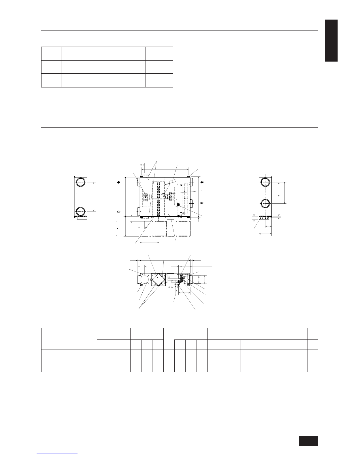
3. Outline drawings
2. Accessories
G
P
M
L
20
100
øH
øJ
C
(N)
A
F
E
N
D
B
79
79
N
T
150 to 250
60
Q
79
R
30
K
Air exhaust fan
Damper plate
Air supply fan
Ceiling suspension fixture (4-13×30 length hole for GUF-50RDH3 · 50RD3)
Ceiling suspension fixture (4-15×30 length hole for GUF-100RDH3 · 100RD3)
RA
(Return air)
Control box
Maintenance cover
EA
(Exhaust air)
High efficiency filter
(Optional part)
Gas pipe
Drain discharge hole
(VP25 connection)
Lossnay core
Liquid pipe
Heat exchanger
Air filters
SA
(Supply air)
OA
(Outdoor air)
Ceiling suspension fixture
Maintenance cover
Location at which the duct direction can be changed
Lossnay core
Air filter
High efficiency filter
Fan
Maintenance space
Inspection
opening
Inspection
opening
Solenoid valve unit with
pressure regulator*
Solenoid valve
Heat exchange unit
Humidifying element
Maintenance space
Power cable
installation port
Can install upper area of ceiling suspension fixture
(GUF-100RDH3 · 100RD3)
Location at which the duct direction can be changed
Humidifying element*
S (Water intake)
(Discharge hole)
Water intake strainer
with check valve*
(PT1/2 External thread)
More than 600
(* GUF-50, 100RDH3 only)
External
Ceiling suspension
Duct connection
Duct pitch Humidification
Inspection
Weight
Model
dimension
fixture pitch
flange
opening
ABCDEF
Nominal
G H J K L M N P Q R S T (kg)
diameter
GUF-50RDH3, GUF-50RD3 1288 1016 317 1185 1048 22 200 158.5 192 208 745 372.5 435 124 347 135 99 266 450
57
(54)
GUF-100RDH3, GUF-100RD3 1580 1231 398 1465 1271 16 250 199 242 258 920 460 670 149 361 169 110 280 600
98
(92)
Unit (mm)
*Values shown in parentheses “( )” are for RD3.
6
ENGLISH
4. Selecting an installation site
• Select a site with sturdy fixed surface sufficiently durable against
the weight of unit.
• Before installing unit, the route to carry the unit to the installation
site should be determined.
• Select a site where the unit is not affected by entering air.
• Select a site where the flow of supply, return, exhaust and outdoor
air is not blocked.
• Select a site where refrigerant piping and exhaust/outdoor ducts
can easily be led to the outside.
•
Select a site which allows the supply air to be distributed fully in room.
• Select a location where the inspection opening can be installed.
•
Do not install unit at a site with oil splashing or steam in large quantities
.
• Do not install unit at a site where combustible gas may generate,
flow in, stagnate or leak.
•
Do not install unit at a site where equipment generating high frequency
waves (a high frequency wave welder for example) is provided.
• Do not install unit at a site where fire detector is located at the
supply air side. (Fire detector may operate erroneously due to the
heated air supplied during heating operation.)
• When special chemical product may be scatter all around such as
site chemical plants and hospitals, full investigation is required before installing unit. (The plastic components may be damaged depending on the chemical product applied.)
• Do not install this product in a refrigerated warehouse, heated swimming pool or other location where the temperature and humidity
are significantly different.
(Failure to heed this warning may result in electrical shock or malfunction.)
• The electro-magnetic susceptibility has been chosen at a level that
gains proper operation in residential areas, on business and light
industrial premises and on small-scale enterprises, inside as well
as outside of the buildings. All places of operation are characterised by their connection to the public low voltage power supply
system.
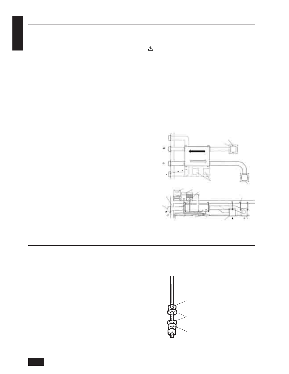
5. Installing the Fresh Master
5.1. Fixing hanging bolts
(Use M10 or M12 hanging bolts. The bolts and washers should be
supplied in the field.)
(Give site of suspension strong structure.)
Hanging structure
• Ceiling: The ceiling structure varies from one building to another.
For detailed information, consult your construction company.
1 Reinforcing the ceiling with additional members (edge beam, etc.)
must be required to keep the ceiling at level and to prevent the
ceiling from vibrations.
2 Cut and remove the ceiling members.
3 Reinforce the ceiling members, and add other members for fixing
the ceiling boards.
• Mount the washers (outer diameter of >21 mm for M10, >24 mm
for M12) and nuts obtained from a field supply onto the pre-recessed
hanging bolts (M10 or M12) also obtained from a field supply, as
shown in the figure.
4.1.
Install the Fresh Master on a ceiling
strong enough to sustain its weight
Warning:
The unit must be securely installed on a structure that can sustain its weight. If the unit is mounted on an unstable structure, it
may fall down causing injuries.
4.2. Securing installation and service
space
• Select the optimum direction of supply airflow according to the configuration of the room and the installation position.
• As the piping and wiring are connected at the side surfaces, and
the maintenance is made at the same surfaces, allow a proper
space properly. For the efficient suspension work and safety, provide a space as much as possible.
4.3. Standard installation examples
Hanging bolt (M10 or M12)
Nut
Washer
Nut
EA
(exhaust)
Maintenance
space
Exhaust grille
Hanging bolt location
Inspection opening
Supply grille
OA
(outdoor)
Duct downward
gradient to wall
(more than 1/30)
Cistern tank
Deionizer
Duct (provided by
customer)
Hanging bolt
(provided by customer)
Deep hood or
weather cover
EA
(exhaust)
OA
(outdoor)
Drain pipe gradient to wall
(more than 1/100)
Supply pipe
Inspection
opening
Servicing
valve
Exhaust
grille
Supply
grille
RA
(return)SA(supply)
7
ENGLISH
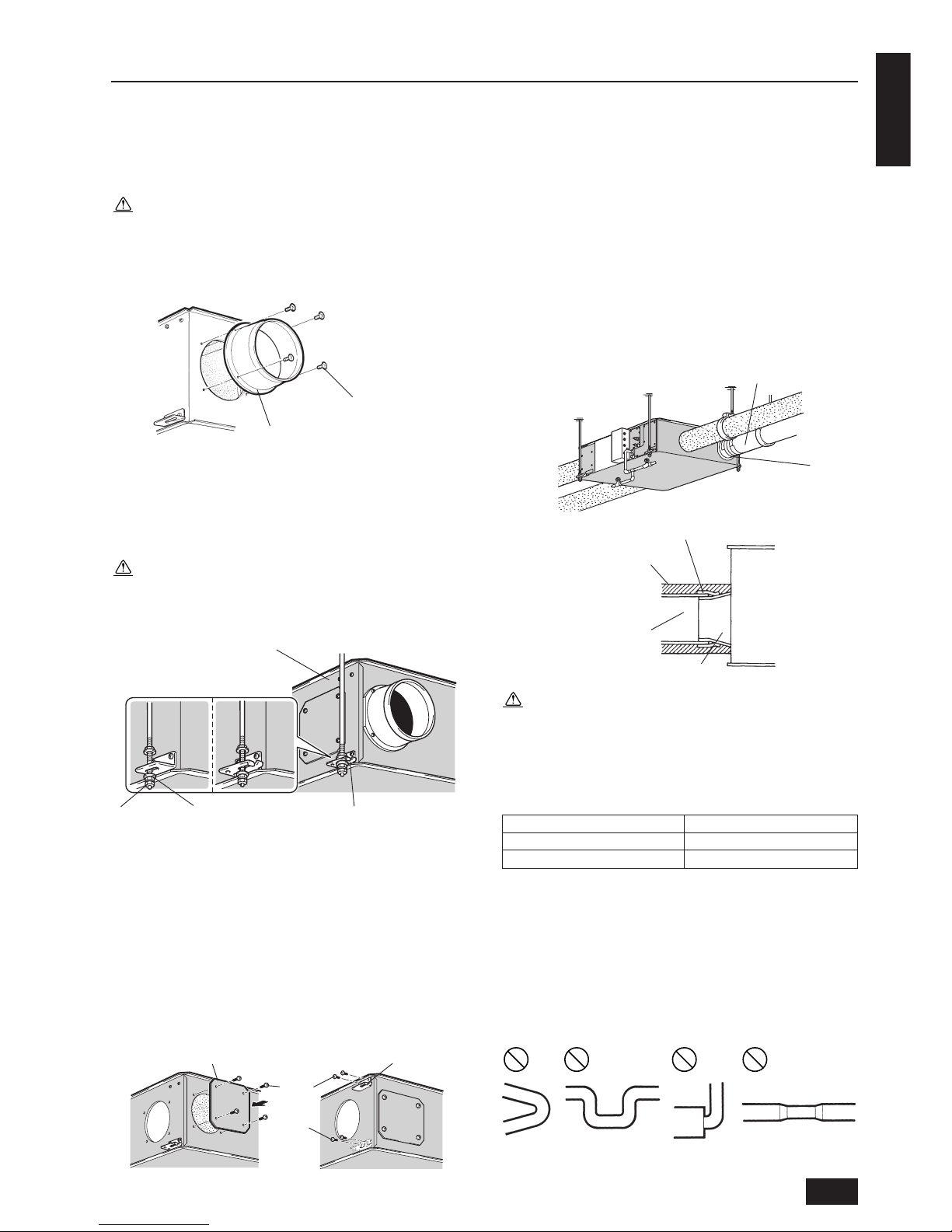
5.2. Attaching the duct connecting
flanges
Use the screws supplied to secure the duct connecting flanges to the
Fresh Master.
Caution:
• Before attaching the duct connecting flanges, check that no
foreign matter (scraps of paper, vinyl, etc.) has found its way
inside the main unit.
• Replace the screws that were removed when the duct connect-
ing flange was removed back in place and securely tighten them.
5.3. Hanging the unit body
1. Hang the ceiling suspension fixtures on the hanging bolts and ad-
just in such a way that the main unit is level.
2. Tighten up securely using double nuts in order to prevent looseness.
Caution:
• When suspending the main unit from the ceiling, do not handle
it in such a way that force will be applied to the control box.
• Fasten the body so that it is oriented horizontally. (within 1˚)
5.4. When changing the direction of
the out door side duct (EA/OA)
Remove the flange cover and suspension fixture.
1. Remove the four mounting screws for the flange cover and remove
the flange cover.
2. Remove the screws at the top mounting position.
3. Remove the ceiling suspension fixtures and attach them at higher
mounting positions.
4. Tighten up the screws in the screw hole where the ceiling suspen-
sion fixtures were removed in order to prevent air leaks.
Mounting the duct connection flange
1. Use the mounting screws provided to mount the duct connection
flange to the main body.
2. Use the four mounting screws that were removed to attach the
flange cover.
5.5. Connecting the ducts
1. Fit the ducts securely into the duct connecting flanges, and wind
aluminium tape available from a field supply around them to prevent air leaks.
2. Suspend the ducts from the ceiling so that their weight will not be
applied to the Fresh Master.
3. The exhaust/outdoor and supply ducts must be covered with heatinsulating material in order to prevent condensation from forming.
Caution:
• The main unit is equipped with connection locations for
equipotential connection of ducts.
• Down ward gradient of outdoor duct: 1/30 or more (toward
wall side)
• Provision of distance for the exhaust/outdoor ducts in table
below (to prevent rain water from seeping in)
Model Distance
GUF-50RDH3, GUF-50RD3 1 m or more
GUF-100RDH3, GUF-100RD
3 2.5 m or more
• Before connecting the ducts, check that no sawdust or any
other foreign matter (scraps of paper, vinyl, etc.) has found its
way inside the ducts.
• Do not touch the damper plate inside the main unit when con-
necting the ducts.
• Do not install the ducts in the ways illustrated below. Doing
so will reduce the air volume and give rise to abnormal sounds.
Mounting screw
Duct connecting flange
Fresh Master
Nut Washer Celling suspension fixture
GUF-100RDH3
GUF-100RD3
GUF-50RDH3
GUF-50RD3
Screw
Flange cover Ceiling suspension fixture
Screw
Duct
Taping
Aluminium tape
Heat-insulating material
Exhaust/outdoor/supply ducts
Duct connecting flange
Main unit
• Extremely
sharp
bends
• Multiple bends
• Bends right next
to the outlet
• Extreme reduction in
the diameter of the
connected ducts

8
ENGLISH
6. Supply pipe and drain pipe work
Supply pipe work is not required for GUF-50 • 100RD3. Only perform
the drain pipe work.
6.1. Supply pipe work
1.
Connect a commercially available interlocked flexible metal hose or
the equivalent between the water supply pipe and the water filler
hole when performing pipe work for the water supply.
• Set the water pressure between 2×10⁴Pa to 49×104Pa.
• Install the servicing valve near the strainer then install the sup-
ply pipe.
Caution:
•
The supply water should meet public waterworks standards, and have
a hardness less than 100 mg/
RR
RR
R, otherwise the humidifier will clog up.
• Install the discharge and servicing valve in locations accessible from the inspection opening.
• Securely lock the supply pipe so that no force is applied to the
strainer.
•
When performing the supply pipe work, wash the pipe with fresh
water prior to installation to prevent saw dust, etc. from entering, or install a discharge valve in the piping and sufficiently
conduct water discharge before using until the water is clear.
•
Take caution as to not let cutting oil or detergent from entering.
• The supply and drain pipes must be installed as such that they
do not rest on the Maintenance cover and cover (humidifier).
• The supply and drain pipes must be properly installed so that
there is no water leak.
• To prevent freezing when not using the unit for long periods
of time, close the servicing valve, open the discharge valve,
and remove the servicing valve and any water in the unitís
supply water entrance. After removing the servicing valve and
water, close the discharge valve.
2. Freeze-prevention work for extremely cold areas
Perform freeze prevention by wrapping a freeze-prevention heater
(field supply) on the supply pipe.
•
Wrap a freeze-prevention heater all the way to the Fresh Master.
• Insulation work must be performed upon the heater as well.
6.2. Drain pipe work
1. Connect a vinyl chloride VP25 elbow to the drain discharge port.
2. The drain pipe must be properly insulated from the drain discharge
port.
Caution:
• The pipe must be installed with gradient of more than 1/100.
• The drain pipe must be installed so that water does not accumulate inside.
• Check to make sure that the end of the drain pipe is at a location where discharge is possible and that the pipe can be properly drained.
• Do not install the drain pipe as shown below.
(This will result in insufficient drainage)
• Do not insert the tip of the drain pipe into a gutter or the like.
Doing so will cause the gutter to freeze in the event of heavy
snowfall, resulting in water leakage from the main unit.
3. Make sure the pipe drains water properly.
(1) Remove the maintenance cover (for humidifying).
• Remove the seven mounting screws, slide the maintenance
cover to the right, and remove it from the potbelly-shaped holes
(six locations for Model 50).
(2) Pull out the inner lid.
(3) Pour approximately 1,000 cc of water onto the drain tray.
(4) Confirm that the drain pipe drains away water at the pipe’s final
exit.
(5) Replace the inner lid and the maintenance cover (for humidifying).
* The diagram shows GUF-50 • 100RDH3
Wrapping the freeze-prevention
heater.
Supply pipe
Servicing valve
Discharge valve
→
Drained
water
Odor trap
Air-bleeding
→
Drained
water
Pass-over
Cap
Drain discharge port
VP25 elbow
Drain pipe (gradient: 1/100 or more)
Vinyl chloride pipe VP25
Maintenance Cover
(humidifier)
Drain tray
Water supply
hose
(field supply)
Innerlid

9
ENGLISH
7. Refrigerant pipe work
7.1. Refrigerant pipe specifications
To avoid dew drops, provide sufficient insulation to the refrigerant and
drain pipes.
When using commercially available refrigerant pipes, be sure to use
commercially available insulation (with a heat-resisting temperature of
more than 100°C and thickness given below) onto both liquid and gas
pipes.
Be also sure to use commercially available insulating material (with a
formed polyethylene’s specific gravity of 0.03 and thickness given below) onto all pipes which pass through rooms.
1 Select the thickness of insulating material by pipe size.
Pipe size Insulating material’s thickness
6.4 mm to 25.4 mm More than 12 mm
28.6 mm to 38.1 mm More than 15 mm
2 If the unit is used on the highest story of a building and under con-
ditions of high temperature and humidity, it is necessary to use
pipe size and insulating material’s thickness more than those given
in the table above.
3 If there are customer’s specifications, simply follow them.
4 Refrigerant pipe specifications
Model
GUF-50RDH3 GUF-100RDH3
Item
GUF-50RD3 GUF-100RD3
Liquid pipe ø6.35 ø9.52
Gas pipe ø12.7 ø15.88
5 Torque specifications
Outerdia of copper pipe Tightening torque
ø6.35 14 ~ 18 N•m
ø9.52 34 ~ 42 N•m
ø12.7 49 ~ 61 N•m
ø15.88 68 ~ 82 N•m
6 Refrigerant system diagram
Refrigerant pipe
(Flare connection)
7.2. Refrigerant piping work
This piping work must be done in accordance with the installation manuals for both outdoor unit and BC controller (simultaneous cooling and
heating series R2).
• With R2 systems connect Fresh Masters to BC controllers.
• For constraints on pipe length and allowable difference of eleva-
tion, refer to the outdoor unit manual.
• The method of pipe connection is flare connection.
Cautions On Refrigerant Piping
s Be sure to use non-oxidative brazing for brazing to ensure
that no foreign matter or moisture enter into the pipe.
s Be sure to apply refrigerating machine oil over the flare con-
nection seating surface and tighten the connection using a
double spanner.
s Provide a metal brace to support the refrigerant pipe so that
no load is imparted to the Fresh Master end pipe. This metal
brace should be provided 50 cm away from the Fresh Master’s
flare connection.
Warning:
When installing and moving the unit, do not charge
it with refrigerant other than the refrigerant (R410A
R407C or R22) specified on the unit.
- Mixing of a different refrigerant, air, etc. may cause the refrigerant
cycle to malfunction and result in severe damage.
Caution:
• Use refrigerant piping made of C1220 (CU-DHP) phosphorus
deoxidized copper as specified in the JIS H3300 “Copper and
copper alloy seamless pipes and tubes”. In addition, be sure
that the inner and outer surfaces of the pipes are clean and
free of hazardous sulphur, oxides, dust/dirt, shaving particles,
oils, moisture, or any other contaminant.
• Never use existing refrigerant piping.
- The large amount of chlorine in conventional refrigerant and
refrigerator oil in the existing piping will cause the new refrigerant to deteriorate.
• Store the piping to be used during installation indoors and
keep both ends of the piping sealed until just before brazing.
- If dust, dirt, or water gets into the refrigerant cycle, the oil will
deteriorate and the compressor may fail.
• Use Suniso 4GS or 3GS (small amount) refrigerator oil to coat
the flare and flange connection part. (For using R22)
• Use ester oil, ether oil or alkylbenzene (small amount) as the
refrigerator oil to coat flares and flange connections. (For using R407C, R410A)
- The refrigerant used in the unit is highly hygroscopic and mixes
with water and will degrade the refrigerator oil.
Gas pipe thermistor TH3
Liquid pipe thermistor TH2
Strainer
Flare
connection
Heat exchanger
Strainer
Linear expansion valve

10
ENGLISH
• Make sure to use new refrigerant piping.
- When using the existing piping which used R22, take care of the
following points.
• Replace the flare nut with that is attached to the product. Flare
section must be finished with the flare processing.
• Use of piping with thin wall should be avoided.
* When applying the flare processing for the refrigerant R410A using conventional
tools, conduct the work referring to the above. If you use the copper pipe gauge
for the adjustment of protrusion margin, you can secure the dimension A.
Pipe Dia. (mm)
ø6.35 (1/4”)
ø9.52 (3/8”)
ø12.7 (1/2”)
ø15.88 (5/8”)
0~0.5
0~0.5
0~0.5
0~0.5
1.0~1.5
1.0~1.5
1.0~1.5
1.0~1.5
1.5~2.0
1.5~2.0
1.5~2.5
1.5~2.5
R410A Flare Tool
When using conventional flare tool (R22/R407C)
Dimension A (mm)
Rigid (clutch type)
Imperial (wing nut) type
Dice
Copper pipe
A
øB
R
0
.4
~
R
0
.8
Copper Pipe O.D.
ø6.35
ø9.52
ø12.7
ø15.88
8.7~9.1
12.8~13.2
16.2~16.6
19.3~19.7
Flare Dimension
Dimension øB (
mm
)
Coat small amount of ester oil, ether oil or hard alkylbenzen oil over
the entire periphery of flare seat surface.
* Do not coat at the threaded section.
(Otherwise, you cannot lock the flare nut securely.)
* Make sure to use only the flare nut attached to the main unit. (Off-the-shelf
product could be cracked.)

11
ENGLISH
No.
1
2
3
Reference drawing
Fig-1
Fig-2 (Note *2)
Fig-2
Fig-3 (Note *3)
Fig-3 (Note *4)
Detail of work
“IN” and “OUT” are marked on the
inside of the flare insulation. Mount the
portion marked “IN” near the unit body
and the portion marked “OUT” on the
field piping side.
• Fasten the insulated pipe with the
insulation tape.
• Firmly secure the insulation with the
provided tie band (4) at the position
indicated on the drawing.
• Fasten the flare insulation with the
provided tape (3).
• Fasten with the provided tie band (4)
at the position indicated on the
drawing.
Item to be observed
• Using the flare insulation of a different type
may result in condensation forming. Check
the type name on the insulation and be sure
to use the correct one.
• To prevent a gap from forming near the
unit’s side plate, be sure that the flare
insulation firmly contacts the unit’s side
plate before mounting.
• Incorrectly mounting the “INNER” and
“OUTER” sides of the insulation may result
in condensation forming.
Seal the slit securely so that there are no
openings. Be sure to mount the insulation so
that the slit is on the top.
Seal the slit securely so that there are no
openings. Be sure to mount the insulation so
that the slit is on the top.
Notes:
*1 Insert the flare nut into the field refrigerant piping. Pull the insulation material back at the area where it will be flared, then return
it to its original position after performing the flare work.
Exposing copper piping may result in condensation forming. Be extremely careful when performing this operation.
*2 There must be no gap.
*3, *4 There must be no gap. Slit should be on the top.
Work procedures
Mount the provided
pipe insulation (1) on
the liquid pipe of the
refrigerant piping, and
then mount the flare
insulation (2) on the
gas pipe.
Fixing of insulated pipe
Fixing of flare insulation
*2
7.3. Request for refrigerant piping connection
Description of parts to be used
*1
20
20
20
20
*3
*4
Fig-1
Fig-2 (figure showing the flare insulation)
Fig-3
“gas” mark
“IN” mark
“OUT” mark
Flare insulation (2)
Refrigerant piping (gas)
Refrigerant piping (liquid)
Field refrigerant piping
Pipe insulation (1)
Insulation material
Flare
Pull in this
direction.
Insulation material
Flare
There must be no gap.
Move to the
original position.
Field refrigerant piping
INNER
There must be no gap.
Unit body plate
OUTER
Unit body
Provided flare insulation
Tape (3)
Fasten with tape.
Provided tie band

12
ENGLISH
8. Electrical wiring
8.1. Precautions on electrical wiring
Warning:
Electrical work should be done by qualified electrical engineers
in accordance with “Engineering Standards For Electrical Installation” and supplied installation manuals. Special circuits should
also be used. If the power circuit lacks capacity or has an installation failure, it may cause a risk of electric shock or fire.
1. Be sure to take power from the special branch circuit.
2. Be sure to install an earth leakage breaker to the power.
3. Install the unit to prevent that any of the control circuit cables (Remote controller, transmission cables) is brought in direct contact
with the power cable outside the unit.
4. Ensure that there is no slack on all wire connections.
5. Some cables (power, Remote controller, transmission cables) above
the ceiling may be bitten by mice. Use as many metal pipes as
possible to insert the cables into them for protection.
6. Never connect the power supply cable to leads for the transmission cables. Otherwise the electronic circuit would be broken.
7. Be sure to connect control cables to the Fresh Master, Remote
controller, and the outdoor unit.
8. Put the unit to the ground on the outdoor unit side.
9. Select control cables from the conditions given below.
Caution:
Be sure to put the unit to the ground on the outdoor unit side. Do
not connect the earth cable to any gas pipe, water pipe, lightening rod, or telephone earth cable. Incomplete grounding may cause
a risk of electric shock.
8.2. Types of control cables
1. Wiring M-NET transmission cables
• Types of transmission cables
Design wiring in accordance with the following table <Table 1>.
• Cable cross-sectional area 1.25 mm2 to 2.00 mm
2
<Table 1>
2. Remote controller cables
Building, clinic, hospital or communications station without noise supposedly generated from inverter equipment, private power generator, highfrequency medical equipment, radioused communications equipment and
so on
Residence or independent
store without noise
Facility example
(for noise judgment)
VCTF, VCTFK, CVV, CVS,
VVR, VVF, VCT or shielding
wire CVVS or CPEVS
Shielding wire CVVS or CPEVS
Types of transmission
cables
System configuration
For a multi-refrigerant system
Transmission cable length Less than 120 m More than 120 m Regardless of length
All facilities
For a single-refrigerant system
MA Remote controller
(PAR-20MAA)
Wire Type
ME Remote controller
(PAR-F27MEA, PAC-SE51CRA)
10 m or shorter
VCTF, VCTFK, CVV, CVS,
VVR, VVF, VCT
If the length exceeds 10 m, keep
the length within the maximum
length of communications lines
between indoor and outdoor
units.
VCTF, VCTFK, CVV, CVS,
VVR, VVF, VCT
Type
2-conductor cable
Number of
conductors
0.3 ~ 1.25 mm2 (Note 1)
(0.75 ~ 1.25 mm2 )(Note 2)
0.3 ~ 1.25 mm2 (Note 1)
Wire diameter
Total Length
Max. 200 m Max. 10 m
M-NET transmission cable
Note1 For work purposes, a wire diameter of 0.75 mm2 is recommended.
Note2 If you are running the wires to the PAC-SE51CRA terminal block, use the wire diameter shown in ( ).
If the length exceeds 10 m.

13
ENGLISH
8.3. Electrical wiring diagram
■ GUF-50 • 100RDH3
• TM1, TM2, TM3 shown in dotted lines are field work.
• Be sure to connect the grounding wire.
• Breakers and controller switches should be provided by the customer.
■ SYMBOL EXPLANATION
■ NOTE 1. TM1,TM2,TM3 shown in dotted lines are field work.
2. Be sure to connect the grounding wire.
3. Breakers should be provided by the customer.
4. MARK : indicates terminal block, : connector, : board insertion connector or fastening connector of control board.
GUF50-100RDH3
M1
M2
C
W.S
SV1
SV2
TH1
TH2
TH3
TH4
LEV
RSV
Symbol Name Symbol Name Symbol Name
TM1
TM2
TM3
SW1
SW2
SW3
SW4
SW5
SW11
SW12
SW14
1, 2
A, B
S
CND1, CND2
X02–X09
TR
GM
LS
LED1
LED2
LED3
Fan motor (exhaust)
Fan motor (supply)
Capacitor
Water sensor
Solenoid valve (pressure regulator)
Solenoid valve (exhaust)
Thermistor (outdoor air temp. detection)
Thermistor (pipe temp. detection/liquid)
Thermistor (pipe temp. detection/gas)
Thermistor (room air temp. detection)
Electronic linear expansion valve
Resistance(solenoid valve)
Terminal block (power supply)
Terminal block (transmission)
Terminal block (humidistat, monitor)
Switch (function selection)
Switch (capacity code setting)
Switch (function selection)
Switch
Switch
Switch (1st digit address set)
Switch (2nd digit address set)
Switch (branch NO. set)
Remote control terminal
M-NET transmission terminal
Shield
Connector (power supply)
Relay
Transformer
Damper motor
Limit switch
Power supply monitor
MA Remote contoller Power supply monitor
M-NET Power supply monitor
1
12
11
10
9
8
7
2
A
B
S
GREEN/YELLOW
BLACK
PINK
ORANGE
WHITE
RED
GREEN/YELLOW
SUPPLY FAN
EXHAUST FAN
ORANGE
BLUE
WHITE
RED
BLACK
PINK
GREEN/YELLOW
M2
M1
BROWN
PINK
PINK
C
C
7
1
5
5
1
ZNR901
ZNR902
DSA1
X05
X04
X07
X06
FUSE1
PURPLE
FAN1
FAN4
CND1 CND2
BLACK
YELLOW
YELLOW
RED
WHITE
WHITE
ORANGE
PURPLE
FAN2
FAN3
SW4
SW5
SV2
SV1
DB901
1
6
1
X02
RSV (1KΩ)
RED
YELLOW
YELLOW
YELLOW
ORANGE
ORANGE
LS
W.S
GM
RED
RED
PURPLE
PURPLE
CN70
CNL
CN27
CN4D
RED
RED
Liquid
pipe
Gas
pipe
TH4 (RA)
TH1 (OA)
YELLOW
YELLOW
WHITE
WHITE
PINK
PINK
GRAY
GRAY
CN22
CN29
CN21
CN20
TH2
TH3
250V 6.3A
SW1
SW2
SW3
SW12
LED1
LED2
SW11
SW14
LED3
BROWN
RED
PURPLE
ORANGE
PINK
WHITE
LEV
CN60
31
TM1
BROWN
BROWN
BLUE
RED
BLUE
BROWN
/YELLOW
TR
CN3TCNT
GREEN
N
L
TM3
TM2
PE
N
L
BREAKER(16A)
220-240V ~ 50Hz
POWER SUPPLY
X09
X08
X03
<PAR-F27MEA>
<PAR-20MAA>
Remote Controller
Uncharged a-contact
Humidistat
240VAC more than 10mA
Operation monitor output
AC240V 1A AC220V 100mA
DC 24V 1A DC 5V 100mA
MAX MIN
Malfunction monitor output
MAX MIN
AC240V 1A AC220V 100mA
DC 24V 1A DC 5V 100mA
Shield wire
M-NET Remote controller
Fresh Master
To Outdoor Unit , BC Controller
M-NET transmissiion cable
■ Warning
Before obtaining access to terminals, all supply circuits
must be disconnected.

14
ENGLISH
■ SYMBOL EXPLANATION
■ GUF-50 • 100RD3
• TM1, TM2, TM3 shown in dotted lines are field work.
• Be sure to connect the grounding wire.
• Breakers and controller switches should be provided by the customer.
M1
M2
C
W.S
TH1
TH2
TH3
TH4
LEV
Symbol Name Symbol Name Symbol Name
TM1
TM2
TM3
SW1
SW2
SW3
SW4
SW5
SW11
SW12
SW14
1, 2
A, B
S
CND1, CND2
X02–X09
TR
GM
LS
LED1
LED2
LED3
Fan motor (exhaust)
Fan motor (supply)
Capacitor
Water sensor
Thermistor (outdoor air temp. detection)
Thermistor (pipe temp. detection/liquid)
Thermistor (pipe temp. detection/gas)
Thermistor (room air temp. detection)
Electronic linear expansion valve
Terminal block (power supply)
Terminal block (transmission)
Terminal block (humidistat, monitor)
Switch (function selection)
Switch (capacity code setting)
Switch (function selection)
Switch
Switch
Switch (1st digit address set)
Switch (2nd digit address set)
Switch (branch NO. set)
Remote control terminal
M-NET transmission terminal
Shield
Connector (power supply)
Relay
Transformer
Damper motor
Limit switch
Power supply monitor
MA Remote contoller Power supply monitor
M-NET Power supply monitor
PINK
PINK
C
C
5
1
5
1
SUPPLY FAN
EXHAUST FAN
BROWN
PURPLE
FAN1
FAN4
BLACK
YELLOW
YELLOW
RED
WHITE
WHITE
ORANGE
PURPLE
ORANGE
BLUE
WHITE
RED
BLACK
PINK
GREEN/YELLOW
GREEN/YELLOW
BLACK
PINK
ORANGE
WHITE
RED
GREEN/YELLOW
M1
M2
FAN2
FAN3
31
ZNR901
X05
X04
X07
X06
FUSE1
BROWN
BROWN
BLUE
RED
BLUE
BROWN
/YELLOW
TR
CN3TCNT
CND1
CND2
GREEN
SW4
SW5
TM3
TM2
X09
X08
X03
BREAKER(16A)
TM1
220-240V ~ 50Hz
POWER SUPPLY
N
L
PE
N
L
B
S
A
2
7
8
9
10
11
1
12
<PAR-F27MEA>
<PAR-20MAA>
Remote Controller
Operation monitor output
AC240V 1A AC220V 100mA
DC 24V 1A DC 5V 100mA
MAX MIN
Malfunction monitor output
MAX MIN
AC240V 1A AC220V 100mA
DC 24V 1A DC 5V 100mA
Shield wire
M-NET Remote controller
Fresh Master
To Outdoor Unit , BC Controller
M-NET transmissiion cable
1
6
X02
Liquid
piping
TH2
Gas
piping
TH3
TH4 (RA)
TH1 (OA)
YELLOW
YELLOW
WHITE
WHITE
RED
PINK
PINK
YELLOW
GRAY
GRAY
YELLOW
YELLOW
ORANGE
ORANGE
CN22
CN29
CN21
CN20
LS
W.S
GM
CNL
CN27
CN4D
DB901
7
1
ZNR902
DSA1
CN70
250V 6.3A
SW1
SW2
SW3
SW12
LED1
LED2
SW11
SW14
LED3
BROWN
RED
PURPLE
ORANGE
PINK
WHITE
LEV
CN60
■ NOTE 1. TM1,TM2,TM3 shown in dotted lines are field work.
2. Be sure to connect the grounding wire.
3. Breakers should be provided by the customer.
4. MARK : indicates terminal block, : connector, : board insertion connector or fastening connector of control board.
■ Warning
Before obtaining access to terminals, all supply circuits
must be disconnected.

15
ENGLISH
8.4. Power supply wiring
Power cable size: 1.5 mm2 or more
[Selecting non-fuse breaker (NF) or earth leakage breaker (NV)]
To select NF or NV instead of a combination of Class B fuse with switch,
use the following:
• In the case of Class B fuse rated 15 A or 20 A,
NF model name (MITSUBISHI): NF30-CS (15 A) (20 A)
NV model name (MITSUBISHI): NV30-CA (15 A) (20 A)
Use an earth leakage breaker with a sensitivity of less than 30 mA 0.1
sec.
Caution:
Do not use anything other than the correct capacity breaker and
fuse. Using fuse, wire or copper wire with too large capacity may
cause a risk of malfunction or fire.
8.5. Connecting the Remote controller,
the Fresh Master and outdoor
transmission cables
(The Remote controller is optionally available.)
• Connect Fresh Master TM2 and outdoor unit TB3. (Non-polarized
2-wire)
The “S” on Fresh Master TM2 is a shielding wire connection. For
specifications about the connecting cables, refer to the outdoor unit
installation manual.
• Install the Remote controller following the manual supplied with the
Remote controller.
[For using the ME Remote controller]
Connect the “A” and “B” on Fresh Master TM2 to the Remote controller. (Non-polarized 2-wire) Connect the Remote controller’s transmission cable within 200 m. If the distance is more than 10 m, use a 1.25
mm2 to 2.0 mm2 cable.
[For using the MA Remote controller]
Connect the “1” and “2” on Fresh Master TM2 to the Remote controller. (Non-polarized 2-wire) Connect the Remote controller’s transmission cable within 200 m.
SBA21 SBA2 1
SBA21
• 24 to 30 V DC between M1 and M2
Longest wiring length (L1+L2+L4 or L1+L3): less than 200 m
Longest wiring length (L2+L3+L4): less than 500 m
Length between the Fresh Master and the Remote controller (R): within
10 m
Notes:
*1 Put the transmission cable earth via the outdoor unit’s earth
terminal to the ground.
*2 If the Remote controller cable exceeds 10 m, use a 1.25 mm2 to
2.0 mm2 cable over the exceeded portion, and add that exceeded portion to within 200 m.
*3 The BC controller is required only for simultaneous cooling
and heating series R2.
[Constraints on transmission cable]
G
I
JJJ
KK
KK
JJ
L
K
H
*1
*3
L1
L2
L4
R
L3
*2
G Outdoor unit
H Earth
I BC controller
J Fresh Master
K Remote controller
L Non-polarized 2-wire
Switch 16 A
Over current
protection 16 A
Total operating current
be less than 16 A
Pull box
Fresh Master
Switch 16 A
Overcurrent
protection 16 A
Fresh Master
Terminal block for outdoor
transmission cable
TM2
(Fresh Master)
TM2
(after Fresh Master)
Terminal block for the
Fresh Master
transmission cable
TB3
MA Remote controller
(PAR-20MAA)
ME Remote
controller
(PAR-F27MEA)

16
ENGLISH
8.6. Connecting electrical connections
1. Remove the 4 screws to remove the control box cover.
2. Install a PG connection or the like, then connect the power supply
cable to the TM1 terminal block.
PE
N
L
Caution:
Wire the power supply so that no tension is imparted. Otherwise
disconnection, heating or fire may result.
3. Connect the transmission line to the TM2 terminal block as shown
in the diagram.
11
10
9
8
7
1
2
A
B
S
12
4. When connecting the humidistat input, remove the short-circuit piece
from the TM3 terminal block as shown in the diagram, then install a
PG connector and connect to the TM3 terminal block.
* The humidistat is the sensor designed specifically for the control of
moisture environment.
The suitable model in this stage :
Uncharged a-contact turns on when atmospheric moisture
content becomes less than your preset minimum allowable
percentage.
Screw
Controller box cover
Terminal block (TM1)
Terminal block for power
supply cable (for TM1)
Grounding wire
PG connection or the like
Power supply cable
Insulation sheet
Terminal block for TM2
M-NET
transmission
cable
Shield
wire
Terminal block (TM3)
Transmission cable
to terminal block for
Fresh Master
outdoor and BC
controller
Humidistat *
Uncharged acontact
240 V AC more
than 10 mA
Short-circuit
piece
Terminal block (TM2)
Humidistat cable
PVC insulated PVC
jacketed control cable 0.75
mm
2
. Recommended type
H03VV-F, H05VV-F.
PAR-20MAA
(Remote
controller)
PG connection
or the like
Terminal block for TM3
Humidistat
Malfunction
monitor
output
Operration
monitor
output
Remote
Controller

17
ENGLISH
9. Feature settings
Caution:
* Always turn off the main power supply.
* Remove the control box cover.
9.1. Address setting
(Determining the address depends on the own-site system. Please
see to technical references, etc.)
Remove the control box cover.
Turn the address setting switch on the board using a Phillips screwdriver.
• The left side (SW12) shows the second digit and the right side
(SW11) shows the first digit.
• The switch is set to 00 when factory shipped.
• Set the address between 1 and 50.
9.2. When using an R2 series external
unit, setting for the branch No. is
also required.
Turn the branch controller No. setting switch (SW14) on the board
using a Phillips screwdriver.
• Set the refrigerant pipe of the external unit and the connected branch
controller to the same number.
• The switch is set to 0 when factory shipped.
9.3. Feature select switches
(SW1, SW3, SW2)
* When shipped from the factory
Items concerning humidifying is for GUF-50 • 100RDH3 only.
SW1
OFF ON
Fan test operation switch (test operation when ON)
Filter maintenance display (displayed when ON)
Filter maintenance time setting switch
Do not touch
Damper motor test operation (test operation when
ON)
Solenoid valve test operation for humidifier water supply (test
operation when ON) Do not touch GUF-50
•
100RD3
Auto-recovery during power failure (active when on)
Power supply ON/OFF (test operation when on)
SW12 SW11 SW14
Second digit First digit Branch No.
SW3 ---- GUF-50 • 100RDH3
OFF ON
Synchronous air-conditioning switch (async when
ON)
Humidifier mode (OFF: humidifier; ON: heat save)
Heater operation during synchronous operation/
stop temperature switch
Exhaust fan operation when supply fan is stopped
(exhaust fan also stopped when ON)
Do not touch
Automatic humidifier control (active when ON)
Do not touch
SW3 ---- GUF-50 • 100RD3
OFF ON
Synchronous air-conditioning switch (async when
ON)
Do not touch
Exhaust fan operation when supply fan is stopped
(exhaust fan also stopped when ON)
Do not touch
Room temperature detected at main unit is decreased
by 4°C when heating. (OFF: active; ON: inactive)
Room-temperature sensor location (OFF: main
unit; ON: remote control)
Do not touch
SW2
OFF ON
Do not touch
Fan speed control method select switch
7: OFF, 8: ON fix to High speed.
Both ONs fix to Low speed.
Do not touch
Notes:
* The switches are vertical for explanation purposes.
1
2
3
4
5
6
7
8
9
10
1
2
3
4
5
6
7
8
9
10
1
2
3
4
5
6
7
8
9
10
1
2
3
4
5
6
7
8
9
10

18
ENGLISH
9.3.1. Filter maintenance time setting
Set the filter maintenance display ON/OFF and time according to use.
2
3
4
2
3
4
3
4
3
4
When the accumulated operation time reaches the set time, indication
for filter cleaning is notified to the Remote controller.
After cleaning, press the filter button twice to reset the accumulated
operation time.
9.3.2. Power-failure auto-recovery select
(independent of Fresh Master)
Set the Fresh Master operation condition when power failure is recovered.
9
9
9.3.3. Power ON feature
Set whether to operate the Fresh Master or not when the main power
is turned ON.
10
10
9.3.4. Indoor unit and synchronous setting
Setting to synchronize with the indoor unit.
1
1
Maintenance time
Filter maintenance display ON
Filter maintenance display OFF*
1,500 hours
3,000 hours*
4,500 hours
Unrestricted
Switch
SW1
OFF ON
Mode
Fresh Master stopped when power failure is
recovered.*
Fresh Master recovers to the prior state when
power failure is recovered.
Switch
SW1
OFF ON
Mode
Inactive: operates according to the SW1-9
setting*
Active: operation starts with power ON
Switch
SW1
OFF ON
9.3.5. Humidifier mode select (GUF-50
•
100RDH3 only)
Setting the humidifier mode.
2
2
Used when operating only the Fresh Master and the temperature during heating becomes too hot. The heating capability can be saved lower
temperature than normal.
9.3.6. Heat operation stop temperature setting
(GUF-50 • 100RDH3 only)
Stopping the heating operation when synchronous with the indoor unit.
It becomes invalid when SW3-1 is ON.
3
4
5
3
4
5
3
4
5
3
4
5
3
4
5
3
4
5
3
4
5
3
4
5
9.3.7. Exhaust fan operation setting
Setting the exhaust fan operation, although the supply fan will stop
when defrosting during heating or when withdrawing the refrigerant.
6
6
9.3.8. Automatic humidifier control setting
(GUF-50
•
100RDH3 only)
Although the permeable-film humidifier is supplied with water for humidifying when heating, there is a feature to automatically stop the
water supply depending on the outside temperature.
8
8
Mode
Synchronizing with the indoor unit*
Asynchronous with the indoor unit. The Remote controller operation only.
Switch
SW3
OFF ON
Mode
Standard humidifier mode*
Heat save humidifier mode (see below)
Switch
SW3
OFF ON
Switch
SW3
OFF ON
Set outside
temperature
6°C
7°C
8°C
9°C
OFF ON
Set outside
temperature
10°C*
12°C
14°C
16°C
Mode
Exhaust fan in operation even when the supply fan is stopped*
Exhaust fan is stopped wen the supply fan is
stopped
Switch
SW3
OFF ON
Mode
Automatic humidifier control prohibited*
Water is supplied to the permeable-film humidifier constantly when the heater is in operation.
Automatic humidifier control permitted
When the outside temperature is below 12°C
during heating operation, supply water to the
permeable-film humidifier.
Switch
SW3
OFF ON

19
ENGLISH
10. Test run
ss
ss
s Read the operation manual, too.
• After installing, piping and wiring the Fresh Master and outdoor
units, make sure again that there is no refrigerant leakage, no slack
on the power and transmission cables, or no polarity mistakes.
• Make sure using a 500 V DC megger that the resistance between
the power terminal bed and ground is more than 2.0 MΩ. If less
than 2.0 MΩ, do not operate the unit.
Warning:
Never measure the insulation resistance of the terminal block for
transmission cables.
Caution:
When operating the Fresh Master for a test run, be sure there is
no water leakage.
■
When operating the Fresh Master for a test run
1 Turn ON the test run switches (1, 7, 8) of the function changeover
switch (SW1).
1
7
8
Notes:
• When the test run switches (1, 7, 8) are turned on, the Remote
controller inspection code “0900” is displayed.
• The operating sound of the damper plate is generated when
the test run switch 7 is turned on. However, it is not abnormal.
2 Turn off the test run switches (1, 7, 8).
9.3.9. Selecting the fan speed control method
This setting is used to select whether to operate according to the fan
speed requested by the indoor unit, or to operate in high or low speed.
7
8
7
8
7
8
7
8
* When factory shipped.
9.3.10. Room temperature control (GUF-50
•
100RD3 only)
Room temperature detected at main unit is decreased by 4°C when
heating.
8
8
9.3.11. Room temperature sensor position
(GUF-50
•
100RD3 only)
9
9
Mode
Following the selected fan speed from controllers.*
Following the selected fan speed from controllers.
High fan speed mode (notch constantly on
high)
Low fan speed mode (notch constantly on
low)
Switch
SW2
OFF ON
Mode
Effective*
Ineffective
Switch
SW3
OFF ON
Mode
Fresh Master’s return air*
Built in the Remote controller.
Switch
SW3
OFF ON
■ When operating the Fresh Master directly
using the Remote controller (SW3-1 is ON)
Operational Procedure
1 Turn ON power at least 12 hours before operation
2 Press [TEST RUN] button twice → displaying “TEST RUN” on the
screen
3 Press [Selecting operation] button → Check that wind is blowing
out
4 Press [Selecting operation] button to change over to cooling (or
heating) → Check that cool (or warm) air is blowing out
5 Press [Fan speed adjustment] button → Check that the wind speed
is changed
6 → Check that the outdoor unit fan is operating
7 Press [ON/OFF] button to clear test run → Test run stops
PAR-F27MEA
ON/OFF
CENTRALLY CONTROLLED
DAILY
AUTO OFF
REMAINDER
CLOCK
ON OFF
˚C
CHECK MODE
FILTER
TEST RUN
LIMIT TEMP.
˚C
1Hr.
NOT AVAILABLE
STAND BY
DEFROST
FILTER
CHECK TEST
TEMP.
TIMER SET
CLOCK→ON→OFF
CHECK
B
C
A
7
5
4
3
2
D
E
A Lighting in operation
B Displaying inspection code
C Displaying remaining test run time
D Displaying indoor unit’s liquid pipe temperature
E Displaying test run
Mode
Power is delivered to the fans for air supply
and exhaust, and they start operating.
The damper motor is powered on, and the
bypass ventilation is activated.
The solenoid valve unit with a pressure regulator that supplies water to the solenoid valve
unit with a pressure regulator for the humidifier is powered on, and water is supplied
(GUF-50·100RDH3 only).
Switch
SW1
OFF ON

20
ENGLISH
Notes:
• It takes a while until warm air comes out when heating. When
cooling, make sure that the display on the remote control
shows “Cooling”.
• The 2-hour-set timer is activated to automatically stop test run
after two hours.
■ When operating the Fresh Master by synchro-
nizing with the indoor unit
During test operation of the indoor unit, press the ventilation button
to operate the Fresh Master simultaneously.
Check to make sure that the mode is the same as the indoor unit
operation mode.
Notes:
• If the Remote controller shows an inspection code or does
not operate normally, refer to the outdoor unit installation
manual.
• The 2-hour-set timer is activated to automatically stop test run
after two hours.
• The Remote controller displays the remaining test run time on
the time display section during test run.
• The Remote controller displays the temperature of the indoor
unit’s liquid pipe on the temperature display section during
test run.
• Depending on the model, the Remote controller displays “This
function is not available” when pressing the [Up/down airflow
selection] button. This is not a malfunction.
Phenomenon
(1) No Remote controller
display appears at all.
(2) No Remote controller
display appears at all.
(3) Inspection code “6600”
flashes.
(4) Inspection code “7107”
flashes.
(5) Inspection code “7106”
flashes.
Cause
• The source power supply is
not turned on.
• Wiring error, short-circuit or
contact failure of transmission
line
• Error in setting the indoor unit
address
There are duplicate address
settings, meaning there are
indoor units with the same
address.
• Error in setting the branch exit
number.
• The Remote controller was
connected with the SW3-1
OFF.
■
In case of abnormality during a test-run operation
If the unit fails to operate normally, check the phenomena and causes
listed below, and correct the problem. (The phenomena listed below
are applicable to the test-run mode.)

21
ENGLISH
11. Troubleshooting
Error code
0900
2600
2601
3602
4116
5101
5102
5103
5104
H0
–
–
See below for possible remedies when there is an error during test operation and [Check] followed by a 4-digit number is displayed on the remote
controller.
Error content
Test run
Drain error
Disconnected water sensor
connector
Damper motor error
Fan motor error
Indoor temperature sensor
error
Liquid pipe temperature
sensor error
Gas pipe temperature sensor
error
Outdoor temperature sensor
error
Booting system
Unable to register.
Operation display comes up
with the Remote controller,
however it turns off immediately.
Cause
• Is the test operation SW of either the fan,
humidifier solenoid valve or bypass damper
turned ON?
• Drain water is not properly discharged.
• Is there a leak from the permeable-film
humidifier?
• Is there a leak from the permeable-film
humidifier?
• When no problem is discovered after
checking the above items.
• Is the CN4D connector firmly connected?
• Is the relay connector between the PCB and
water sensor firmly connected?
• When no problem is discovered after
checking the above item.
• Is the CNL connector firmly connected?
• Is the connector of the damper motor
section firmly connected?
• Does the damper operate when the damper
motor is running?
• When no problem is discovered after
checking the above items.
• The motor continues to run when the
operation is stopped.
• Are the connectors of each thermister firmly
connected?
• Is each relay connector firmly connected?
• When no problem is discovered after
checking the above item.
• Has 10 minutes passed since system bootup?
• Has group registration been made?
• Has the Fresh Master address been
changed?
• When no problem is discovered after
checking the above items.
• The Fresh Master which is linked with air
conditioner, cannot be group registered
other than the interlock setting with the
Remote controller.
• Main power hasn’t supplied to the Fresh
Master.
Remedy
• Set the test operation SW (SW1-1, 7, 8) to
OFF.
• The body must be levelly installed.
The drain pipe must be installed with
gradient of more than 1/100.
• Fix the water leak.
• Replace the permeable-film humidifier.
• Replace the PCB (printed circuit board).
• Firmly connect the connector.
• Firmly connect the connector.
• Replace the PCB (printer circuit board).
• Firmly connect the connector.
• Firmly connect the connector.
• Replace the damper motor if not working.
• Replace the PCB (printed circuit board).
• Replace the PCB (printed circuit board).
• Firmly connect each connector.
• Firmly connect each connector.
• Replace the PCB (printed circuit board).
• After system boot-up, HO may flash for a
maximum of 10 minutes. However, this is
not a malfunction.
• Conduct group registration. If there is a
master system controller such as the central
controller, use the controller to conduct
group registration.
• If the Fresh Master main unit address has
been changed, conduct the group registration again.
• If HO continues to flash for more than 10
minutes after reregistering the group and
rebooting, replace the PCB (printed circuit
board).
• Change the setting of the SW3-1 switch and
reset the registration or register it interlocked.
• Supply Main Power.

22
ENGLISH
 Loading...