

Mitsubishi Electric Fresh Master GUF-50RD3, Fresh Master GUF-50RDH3, Fresh Master GUF-100RDH3, Fresh Master GUF-100RD3 Installation Instructions Manual

ENGLISH
Fresh Master
Models:
GUF-50RDH3 • GUF-50RD3
GUF-100RDH3
•
GUF-100RD3
Installation Instructions
(For use by dealer/contractor)
For use with the R410A&R407C&R22
• Please take the time to read through these instructions before commencing with the installation work.
They will help to install the Fresh Master properly and
safely.
• The separate Operating Instructions are for the user.
Make sure that they are handed over to the customer.
The warranty will not apply to damage resulting
from failure to follow the warnings and precautions set forth in the
Installation Instructions
.
GUF-50RDH3 shown above.
Humidifier function not available on GUF-50RD3 and
GUF-100RD3.
Contents
1. Safety precautions ............................................ 2-4
2. Accessories .......................................................... 5
3. Outline drawings .................................................. 5
4. Selecting an installation site ................................. 6
5. Installing the Fresh Master ................................6-7
6. Supply pipe and drain pipe work .......................... 8
7. Refrigerant pipe work ...................................... 9-11
8. Electrical wiring .............................................12-16
9. Feature settings ............................................ 17-19
10. Test run ......................................................... 19-20
11. Troubleshooting ................................................. 21
2
ENGLISH
1. Safety precautions
3 ) Remote controller
Warning:
The Remote controller should be installed in such a way that children cannot play with it.
4) Drain hose
Caution:
Make sure that the drain hose is installed so that drainage can go
ahead smoothly. Incorrect installation may result in water leakage, causing damage to furniture.
5 ) Power Supply, fuse or circuit breaker
Warning:
•
Make sure that the unit is powered by a dedicated power supply.
Other appliances connected to the same power supply could
cause an overload.
• Make sure that there is a mains power switch.
• Be sure to adhere to the unit’s voltage and fuse circuit breaker
ratings. Never use a cable or a fuse with a higher rating than
the one specified.
6 ) Grounding
Caution:
• The unit must be properly grounded. Never connect the
grounding wire to a gas pipe, water pipe, lightning conductor
or telephone grounding wire. If the unit is not grounded properly, electric shock may result.
• Check frequently that the ground wire from the outdoor unit is
properly connected to both the unit’s ground terminal and the
grounding electrode.
ss
ss
s Before operating the unit, make sure you read
all the “Safety precautions”.
ss
ss
s “Safety precautions” lists important points about
safety. Please be sure to follow them.
Symbols used in the text
Warning:
Describes precautions that should be observed to avoid the risk
of injury or death to the user.
Caution:
Describes precautions that should be observed to prevent damage to the unit.
Symbols used in the illustrations
: Indicates that important instructions must be followed.
: Indicates a part which must be grounded.
: Beware of electric shock. (This symbol is displayed on the main
unit label.) <Colour: Yellow>
Warning:
Carefully read the labels affixed to the main unit.
1.1. Installation
ss
ss
s After you have read this manual, keep it and the Installation
Manual in a safe place for easy reference whenever a question
arises. If the unit is going to be operated by another person,
make sure that this manual is given to him or her.
Warning:
• The unit should not be installed by the user. Ask the dealer or
an authorized company to install the unit. If the unit is installed
improperly, water leakage, electric shock or fire may result.
• Use only accessories authorized by Mitsubishi Electric and
ask your dealer or an authorized company to install them. If
accessories are installed improperly, water leakage, electric
shock or fire may result.
• The Installation Manual details the suggested installation
method. Any structural alteration necessary for installation
must comply with local building code requirements.
• Never repair the unit or transfer it to another site by yourself.
If repair is performed improperly, water leakage, electric shock
or fire may result. If you need to have the unit repaired or
moved, consult your dealer.
1 ) Outdoor unit
Warning:
• The outdoor unit must be installed on a stable, level surface,
in a place where there is no accumulation of snow, leaves or
rubbish.
• Do not stand on, or place any items on the unit. You may fall
down or the item may fall, causing injury.
Caution:
The outdoor unit should be installed in a location where air and
noise emitted by the unit will not disturb the neighbours.
2) Fresh Master
Warning:
The Fresh Master should be securely installed. If the unit is loosely
mounted, it may fall, causing injury.
3
ENGLISH
1.2. Precautions for devices that use
R407C refrigerant
Caution:
• Do not use the existing refrigerant piping.
- The old refrigerant and refrigerator oil in the existing piping contains a large amount of chlorine which may cause the refrigerator
oil of the new unit to deteriorate.
• Use refrigerant piping made of C1220 (CU-DHP) phosphorus
deoxidized copper as specified in the JIS H3300 “Copper and
copper alloy seamless pipes and tubes”. In addition, be sure
that the inner and outer surfaces of the pipes are clean and
free of hazardous sulphur, oxides, dust/dirt, shaving particles,
oils, moisture, or any other contaminant.
- Contaminants on the inside of the refrigerant piping may cause
the refrigerant residual oil to deteriorate.
• Store the piping to be used during installation indoors and
keep both ends of the piping sealed until just before brazing.
(Store elbows and other joints in a plastic bag.)
- If dust, dirt, or water enters the refrigerant cycle, deterioration of
the oil and compressor trouble may result.
• Use ester oil, ether oil or alkylbenzene (small amount) same
as the refrigerator oil to coat flares and flange connections.
- The refrigerator oil will degrade if it is mixed with a large amount
of mineral oil.
• Use liquid refrigerant to fill the system.
-
If gas refrigerant is used to seal the system, the composition of the
refrigerant in the cylinder will change and performance may drop.
• Do not use a refrigerant other than R407C.
- If another refrigerant (R22, etc.) is used, the chlorine in the refrig-
erant may cause the refrigerator oil to deteriorate.
• Use a vacuum pump with a reverse flow check valve.
- The vacuum pump oil may flow back into the refrigerant cycle
and cause the refrigerator oil to deteriorate.
• Do not use the following tools that are used with conventional
refrigerants.
(Gauge manifold, charge hose, gas leak detector, reverse flow
check valve, refrigerant charge base, vacuum gauge, refrigerant recovery equipment)
- If the conventional refrigerant and refrigerator oil are mixed in the
R407C, the refrigerant may deteriorate.
-
If water is mixed in the R407C, the refrigerator oil may deteriorate.
- Since R407C does not contain any chlorine, gas leak detectors
for conventional refrigerants will not react to it.
• Do not use a charging cylinder.
-
Using a charging cylinder may cause the refrigerant to deteriorate.
• Be especially careful when managing the tools.
- If dust, dirt, or water gets in the refrigerant cycle, the refrigerant
may deteriorate.
1.3. Precautions for devices that use
R410A refrigerant
• Make sure to use new refrigerant piping.
- When using the existing piping which used R22, take care of the
following points.
• Replace the flare nut with that is attached to the product. Flare
section must be finished with the flare processing. (See P.10.)
• Use of piping with thin wall should be avoided. (See P.10.)
• Use refrigerant piping made of C1220 (CU-DHP) phosphorus
deoxidized copper as specified in the JIS H3300 “Copper and
copper alloy seamless pipes and tubes”. The pipes must have
the wall thickness as shown in the table below. In addition, be
sure that the inner and outer surfaces of the pipes are clean
and free of hazardous sulphur, oxides, dust/dirt, shaving
particles, oils, moisture, or any other contaminant.
It is strictly prohibited to use pipes with thin wall not listed in
the above table.
If the inside of pipe is contaminated, it could cause deterioration of
refrigerator oil, or other problems.
• Store the piping to be used during installation indoors and
keep both ends of the piping sealed until just before brazing.
(Store elbows and other joints in a plastic bag.)
- If dust, dirt, or water enters the refrigerant cycle, deterioration of
the oil and compressor trouble may result.
• Use ester oil, ether oil or alkylbenzene (small amount) same
as the refrigerator oil to coat flares and flange connections.
- The refrigerator oil will degrade if it is mixed with a large amount
of mineral oil.
• Do not use a refrigerant other than R410A.
- If another refrigerant (R22, etc.) is used, the chlorine in the refrigerant
may cause the refrigerator oil to deteriorate.
• Use a vacuum pump with a reverse flow check valve.
- The vacuum pump oil may flow back into the refrigerant cycle
and cause the refrigerator oil to deteriorate.
• For the following tools, use only the tools special to the
refrigerant R410A.
- Tools as listed in the following table are required for the refrigerant
R410A.
• Be especially careful when managing the tools.
- If dust, dirt, or water gets in the refrigerant cycle, the refrigerant
may deteriorate.
• Do not use a charging cylinder.
-
Using a charging cylinder may cause the refrigerant to deteriorate.
1.4. Before conducting supply pipe
and drain pipe work
[Supply pipe work is not required for GUF-50 • 100RD3]
Caution:
• The water quality of the permeable film humidifier's supply
water should meet public waterworks standards, and have a
hardness less than 100 mg/
RR
RR
R. If the supply water does not
meet these standards, use a deionizer.
• The supply pressure must be within the range of 2×10⁴pa to
49×104pa.
-
Supply pressure that is lower than the specified range will cause the
water to not supplied the permeable-film humiditier, and the humidifier may not work. Supply pressure that exceeds the specified range
may cause damage to the solenoid valve and result in water leaks.
• Drain pipe gradient must be more than 1/100.
- Drain water will not be properly discharged.
• For areas that are extremely cold in winter, perform freezeprevention on the supply pipe by wrapping a freeze prevention heater and thermal insulation.
- Cold temperatures may freeze water, and damage supply pipe.
• Install the drain piping according to this installation Manual
to ensure proper drainage. Wrap thermal insulation around
the pipes to prevent condensation.
- Improper drain piping may cause water leakage and damage to
furniture and other possessions.
ø6.35, Wall thickness 0.8 mm
ø12.7, Wall thickness 0.8 mm
ø9.52, Wall thickness 0.8 mm
ø15.88, Wall thickness 1.0 mm
Gauge manifold
Charging hose
Gas leak detector
Torque wrench
Tool name (For R410A)
Flare tool
Protrusion adjust copper pipe gauge
Vacuum pump adaptor
Balance for refrigerant charging

4
ENGLISH
1.5. Before getting installed
Caution:
• Do not install the unit where combustible gas may leak.
- If the gas leaks and accumulates around the unit, an explosion
may result.
• Do not use the Fresh Master where food, pets, plants, precision instruments, or artwork are kept.
- The quality of the food, etc. may deteriorate.
• Do not use the Fresh Master in special environments.
- Oil, steam, sulfuric smoke, etc. can significantly reduce the per-
formance of the Fresh Master or damage its parts.
• When installing the unit in a hospital, communication station,
or similar place, provide sufficient protection against noise.
-
The inverter equipment, private power generator, high-frequency
medical equipment, or radio communication equipment may cause
the Fresh Master to operate erroneously, or fail to operate. On the
other hand, the Fresh Master may affect such equipment by creating noise that disturbs medical treatment or image broadcasting.
• Do not install the unit on a structure that may cause leakage.
- When the room humidity exceeds 80% or when the drain pipe is
clogged, condensation may drip from the Fresh Master. Perform
collective drainage work together with the outdoor unit, as required.
1.6. Before getting installed (moved) -
electrical work
Caution:
• Ground the unit.
- Do not connect the ground wire to gas or water pipes, lightning
rods, or telephone ground lines. Improper grounding may result
in electric shock.
•
Install the power cable so that tension is not applied to the cable.
- Tension may cause the cable to break and generate heat and
cause a fire.
• Install an leak circuit breaker, as required.
- If an leak circuit breaker is not installed, electric shock may re-
sult.
• Use power line cables of sufficient current carrying capacity
and rating.
-
Cables that are too small may leak, generate heat, and cause a fire.
• Use only a circuit breaker and fuse of the specified capacity.
- A fuse or circuit breaker of a larger capacity or a steel or copper
wire may result in a general unit failure or fire.
• Do not wash the Fresh Master.
- Washing them may cause an electric shock.
•
Be careful that the installation base is not damaged by long use.
- If the damage is left uncorrected, the unit may fall and cause
personal injury or property damage.
• Be very careful about product transportation.
- Only one person should not carry the product if it weighs more
than 20 kg.
- Fresh Master use PP bands for packaging. Do not use any PP
bands for a means of transportation. It is dangerous.
- Do not touch the heat exchanger fins. Doing so may cut your
fingers.
- When transporting the outdoor unit, suspend it at the specified
positions on the unit base. Also support the outdoor unit at four
points so that it cannot slip sideways.
• Safely dispose of the packing materials.
- Packing materials, such as nails and other metal or wooden parts,
may cause stabs or other injuries.
- Tear apart and throw away plastic packaging bags so that chil-
dren can not play with them. If children play with a plastic bag
which was not torn apart, they face the risk of suffocation.
1.7. Before starting the test run
Caution:
• Turn on the power at least 12 hours before starting operation.
- Starting operation immediately after turning on the main power
switch can result in severe damage to internal parts. Keep the
power switch turned on during the operational season.
• Do not touch the switches with wet fingers.
- Touching a switch with wet fingers can cause electrification.
• Do not touch the refrigerant pipes during and immediately after operation.
- During and immediately after operation, the refrigerant pipes are
may be hot or cold, depending on the condition of the refrigerant
flowing through the refrigerant piping, compressor, and other refrigerant cycle parts. Your hands may suffer burns or frostbite if
you touch the refrigerant pipes.
• Do not operate the Fresh Master and outdoor unit with the
panels and guards removed.
- Rotating, hot, or high-voltage parts can cause injuries.
• Do not turn off the power immediately after stopping operation.
- Always wait at least five minutes before turning off the power.
Otherwise, water leakage and trouble may occur.
5
ENGLISH
The unit is provided with the following accessories:
No. Accessories Qty
1 Pipe insulation 1
2 Flare insulation 1
3 Tie band 6
4 Duct connecting flanges 4
5 Mounting screws 16
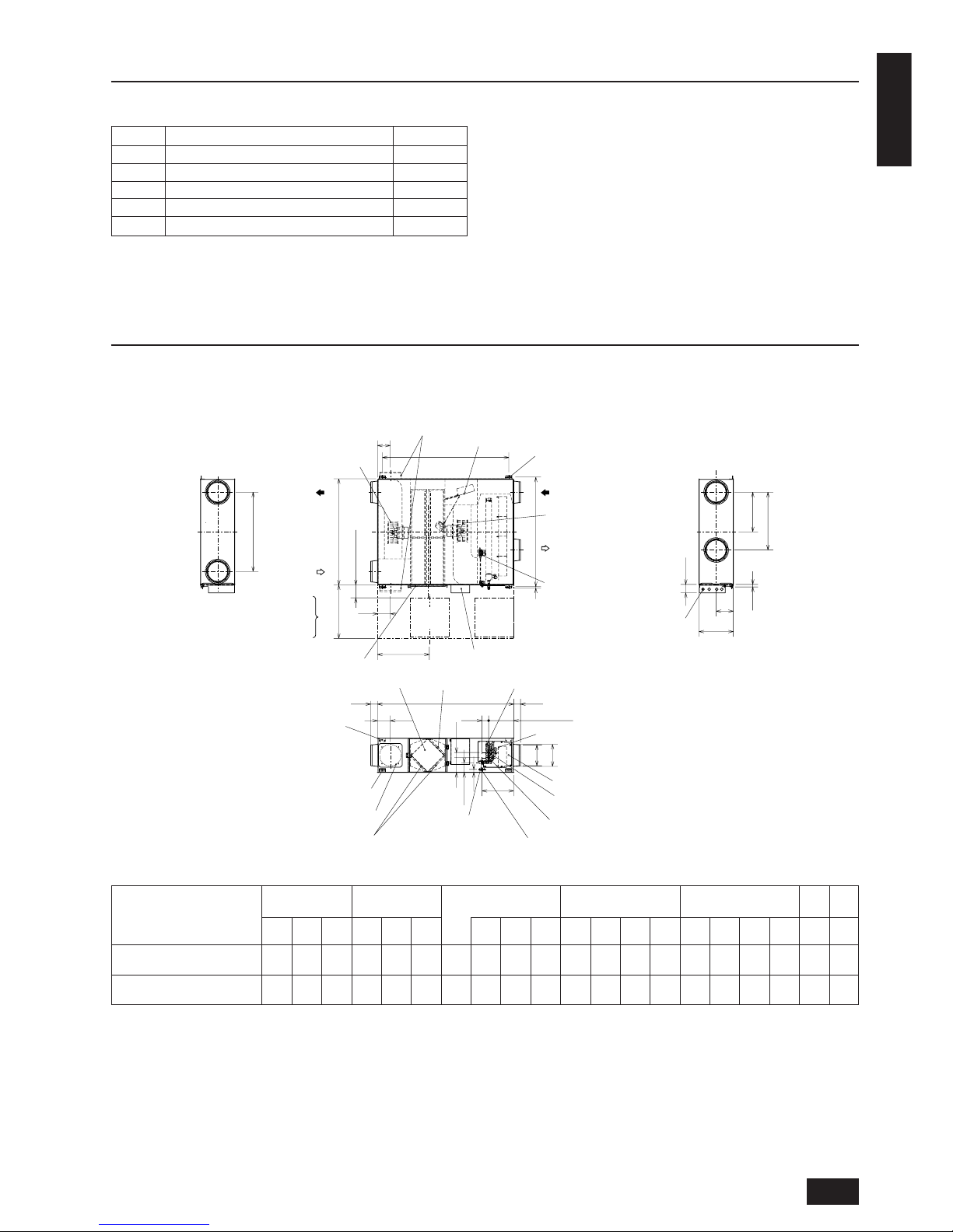
3. Outline drawings
2. Accessories
G
P
M
L
20
100
øH
øJ
C
(N)
A
F
E
N
D
B
79
79
N
T
150 to 250
60
Q
79
R
30
K
Air exhaust fan
Damper plate
Air supply fan
Ceiling suspension fixture (4-13×30 length hole for GUF-50RDH3 · 50RD3)
Ceiling suspension fixture (4-15×30 length hole for GUF-100RDH3 · 100RD3)
RA
(Return air)
Control box
Maintenance cover
EA
(Exhaust air)
High efficiency filter
(Optional part)
Gas pipe
Drain discharge hole
(VP25 connection)
Lossnay core
Liquid pipe
Heat exchanger
Air filters
SA
(Supply air)
OA
(Outdoor air)
Ceiling suspension fixture
Maintenance cover
Location at which the duct direction can be changed
Lossnay core
Air filter
High efficiency filter
Fan
Maintenance space
Inspection
opening
Inspection
opening
Solenoid valve unit with
pressure regulator*
Solenoid valve
Heat exchange unit
Humidifying element
Maintenance space
Power cable
installation port
Can install upper area of ceiling suspension fixture
(GUF-100RDH3 · 100RD3)
Location at which the duct direction can be changed
Humidifying element*
S (Water intake)
(Discharge hole)
Water intake strainer
with check valve*
(PT1/2 External thread)
More than 600
(* GUF-50, 100RDH3 only)
External
Ceiling suspension
Duct connection
Duct pitch Humidification
Inspection
Weight
Model
dimension
fixture pitch
flange
opening
ABCDEF
Nominal
G H J K L M N P Q R S T (kg)
diameter
GUF-50RDH3, GUF-50RD3 1288 1016 317 1185 1048 22 200 158.5 192 208 745 372.5 435 124 347 135 99 266 450
57
(54)
GUF-100RDH3, GUF-100RD3 1580 1231 398 1465 1271 16 250 199 242 258 920 460 670 149 361 169 110 280 600
98
(92)
Unit (mm)
*Values shown in parentheses “( )” are for RD3.
6
ENGLISH
4. Selecting an installation site
• Select a site with sturdy fixed surface sufficiently durable against
the weight of unit.
• Before installing unit, the route to carry the unit to the installation
site should be determined.
• Select a site where the unit is not affected by entering air.
• Select a site where the flow of supply, return, exhaust and outdoor
air is not blocked.
• Select a site where refrigerant piping and exhaust/outdoor ducts
can easily be led to the outside.
•
Select a site which allows the supply air to be distributed fully in room.
• Select a location where the inspection opening can be installed.
•
Do not install unit at a site with oil splashing or steam in large quantities
.
• Do not install unit at a site where combustible gas may generate,
flow in, stagnate or leak.
•
Do not install unit at a site where equipment generating high frequency
waves (a high frequency wave welder for example) is provided.
• Do not install unit at a site where fire detector is located at the
supply air side. (Fire detector may operate erroneously due to the
heated air supplied during heating operation.)
• When special chemical product may be scatter all around such as
site chemical plants and hospitals, full investigation is required before installing unit. (The plastic components may be damaged depending on the chemical product applied.)
• Do not install this product in a refrigerated warehouse, heated swimming pool or other location where the temperature and humidity
are significantly different.
(Failure to heed this warning may result in electrical shock or malfunction.)
• The electro-magnetic susceptibility has been chosen at a level that
gains proper operation in residential areas, on business and light
industrial premises and on small-scale enterprises, inside as well
as outside of the buildings. All places of operation are characterised by their connection to the public low voltage power supply
system.
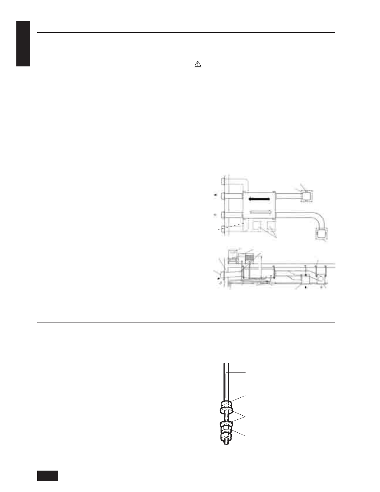
5. Installing the Fresh Master
5.1. Fixing hanging bolts
(Use M10 or M12 hanging bolts. The bolts and washers should be
supplied in the field.)
(Give site of suspension strong structure.)
Hanging structure
• Ceiling: The ceiling structure varies from one building to another.
For detailed information, consult your construction company.
1 Reinforcing the ceiling with additional members (edge beam, etc.)
must be required to keep the ceiling at level and to prevent the
ceiling from vibrations.
2 Cut and remove the ceiling members.
3 Reinforce the ceiling members, and add other members for fixing
the ceiling boards.
• Mount the washers (outer diameter of >21 mm for M10, >24 mm
for M12) and nuts obtained from a field supply onto the pre-recessed
hanging bolts (M10 or M12) also obtained from a field supply, as
shown in the figure.
4.1.
Install the Fresh Master on a ceiling
strong enough to sustain its weight
Warning:
The unit must be securely installed on a structure that can sustain its weight. If the unit is mounted on an unstable structure, it
may fall down causing injuries.
4.2. Securing installation and service
space
• Select the optimum direction of supply airflow according to the configuration of the room and the installation position.
• As the piping and wiring are connected at the side surfaces, and
the maintenance is made at the same surfaces, allow a proper
space properly. For the efficient suspension work and safety, provide a space as much as possible.
4.3. Standard installation examples
Hanging bolt (M10 or M12)
Nut
Washer
Nut
EA
(exhaust)
Maintenance
space
Exhaust grille
Hanging bolt location
Inspection opening
Supply grille
OA
(outdoor)
Duct downward
gradient to wall
(more than 1/30)
Cistern tank
Deionizer
Duct (provided by
customer)
Hanging bolt
(provided by customer)
Deep hood or
weather cover
EA
(exhaust)
OA
(outdoor)
Drain pipe gradient to wall
(more than 1/100)
Supply pipe
Inspection
opening
Servicing
valve
Exhaust
grille
Supply
grille
RA
(return)SA(supply)
7
ENGLISH
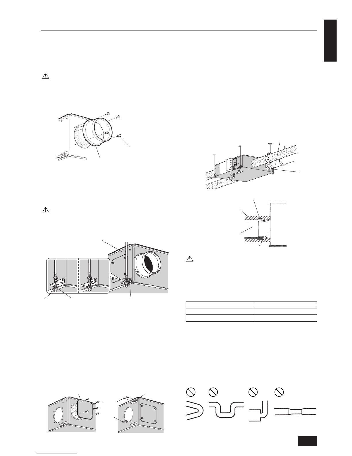
5.2. Attaching the duct connecting
flanges
Use the screws supplied to secure the duct connecting flanges to the
Fresh Master.
Caution:
• Before attaching the duct connecting flanges, check that no
foreign matter (scraps of paper, vinyl, etc.) has found its way
inside the main unit.
• Replace the screws that were removed when the duct connect-
ing flange was removed back in place and securely tighten them.
5.3. Hanging the unit body
1. Hang the ceiling suspension fixtures on the hanging bolts and ad-
just in such a way that the main unit is level.
2. Tighten up securely using double nuts in order to prevent looseness.
Caution:
• When suspending the main unit from the ceiling, do not handle
it in such a way that force will be applied to the control box.
• Fasten the body so that it is oriented horizontally. (within 1˚)
5.4. When changing the direction of
the out door side duct (EA/OA)
Remove the flange cover and suspension fixture.
1. Remove the four mounting screws for the flange cover and remove
the flange cover.
2. Remove the screws at the top mounting position.
3. Remove the ceiling suspension fixtures and attach them at higher
mounting positions.
4. Tighten up the screws in the screw hole where the ceiling suspen-
sion fixtures were removed in order to prevent air leaks.
Mounting the duct connection flange
1. Use the mounting screws provided to mount the duct connection
flange to the main body.
2. Use the four mounting screws that were removed to attach the
flange cover.
5.5. Connecting the ducts
1. Fit the ducts securely into the duct connecting flanges, and wind
aluminium tape available from a field supply around them to prevent air leaks.
2. Suspend the ducts from the ceiling so that their weight will not be
applied to the Fresh Master.
3. The exhaust/outdoor and supply ducts must be covered with heatinsulating material in order to prevent condensation from forming.
Caution:
• The main unit is equipped with connection locations for
equipotential connection of ducts.
• Down ward gradient of outdoor duct: 1/30 or more (toward
wall side)
• Provision of distance for the exhaust/outdoor ducts in table
below (to prevent rain water from seeping in)
Model Distance
GUF-50RDH3, GUF-50RD3 1 m or more
GUF-100RDH3, GUF-100RD
3 2.5 m or more
• Before connecting the ducts, check that no sawdust or any
other foreign matter (scraps of paper, vinyl, etc.) has found its
way inside the ducts.
• Do not touch the damper plate inside the main unit when con-
necting the ducts.
• Do not install the ducts in the ways illustrated below. Doing
so will reduce the air volume and give rise to abnormal sounds.
Mounting screw
Duct connecting flange
Fresh Master
Nut Washer Celling suspension fixture
GUF-100RDH3
GUF-100RD3
GUF-50RDH3
GUF-50RD3
Screw
Flange cover Ceiling suspension fixture
Screw
Duct
Taping
Aluminium tape
Heat-insulating material
Exhaust/outdoor/supply ducts
Duct connecting flange
Main unit
• Extremely
sharp
bends
• Multiple bends
• Bends right next
to the outlet
• Extreme reduction in
the diameter of the
connected ducts
 Loading...