

MITSUBISHI
VVVF TRANSISTOR INVERTER
-
INSTRUCTION MANUAL
-
0
MlTSUBlSHl
A
ELECTRIC
.- .
Introduction
Thank you for your purchase of MiBubishi Micro-Inverter
FREQROL-2024-UL.
Before operating the inverter, read this manual carefully. Please deliver
this
instruction manual
to
the
actual
user
of
the inverter.
CONTENTS
Instructions
1
.
Precautions
......................................................................................................
1
2
.
Block Diagram and Description
......................................................................
7
3
.
Preparation before Operation
.........................................................................
11
4 . Apparatus and Components
to
be Prepared before Operation
....................
13
5
.
Installation
.......................................................................................................
15
6
.
Wiring
...............................................................................................................
17
7
.
Pre-Operation Settings
...................................................................................
26
8
.
Operation
.........................................................................................................
30
9
.
Using the Parameter Unit
...............................................................................
38
10
.
Parameter Unit Installation
.............................................................................
40
11 . Outline
of
Parameter Unit Functions
..............................................................
42
12
.
Operation
.........................................................................................................
43
Selecting operation mode
...............................................................................
43
Operating the motor with the parameter unit
.................................................
46
Settings
of
control variables (Parameters)
....................................................
51
Monitor
.............................................................................................................
55
Frequency meter calibration
...........................................................................
64
Adjusting bias and gain for frequency reference signal
................................
66
Cautions for
PU
operation
..............................................................................
69
13
.
Details
of
Each Parameter
..............................................................................
72
14 .
Maintenance and Inspection
...........................................................................
102
15
.
Troubleshooting
..............................................................................................
109
16 . Specifications
................................................................................................
113
17
.
DIMENSIONS
..................................................................................................
127
18
.
Selection of Peripheral Devices
.....................................................................
133
I
Handling Instructions
I
BUR
.
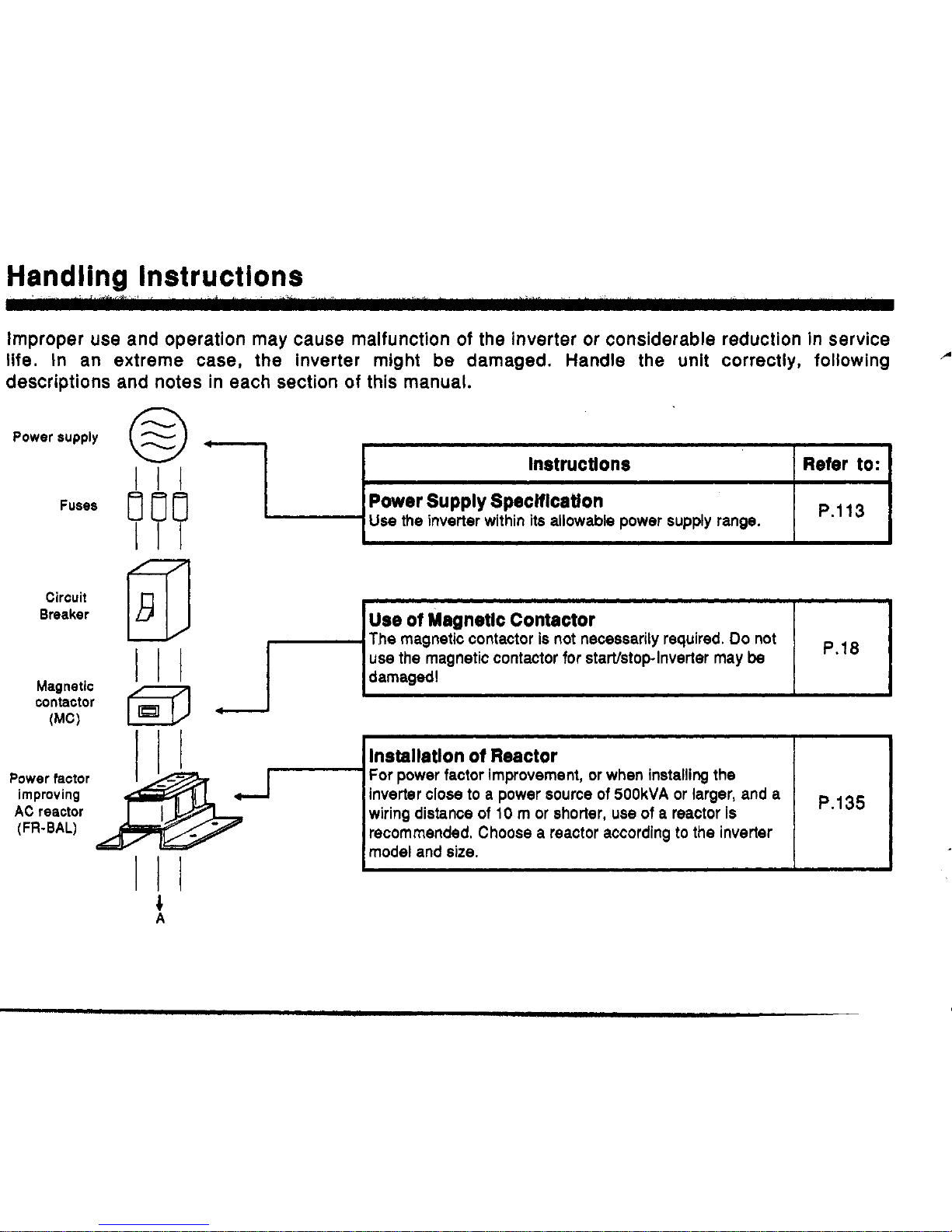
Improper use and operation may cause malfunction of the inverter
or
considerable reduction in service
life. In an extreme case, the inverter might be damaged. Handle the unit correctly, following
-'
descriptions and notes in each section
of
this manual.
P.113
Power Supply Speclflcatlon
Use
the
inverter within
its
allowable power supply range.
Power supply
~ ~~
Instructlons
I
Refer
to:
I
Fuses
Circuit
Breaker
Magnetic
contactor
(MC)
I
I
I
Power factor
improving
AC
reactor
(FR-BAL)
Ill
lnstallatlon
of
Reactor
For power factor improvement, or when installing the
wiring distance of
10
m
or
shorter,
use
of a reactor
is
recommended. Choose a reactor according
to
the
inverter
model and size.
Ill
Handling Instructions
A
til
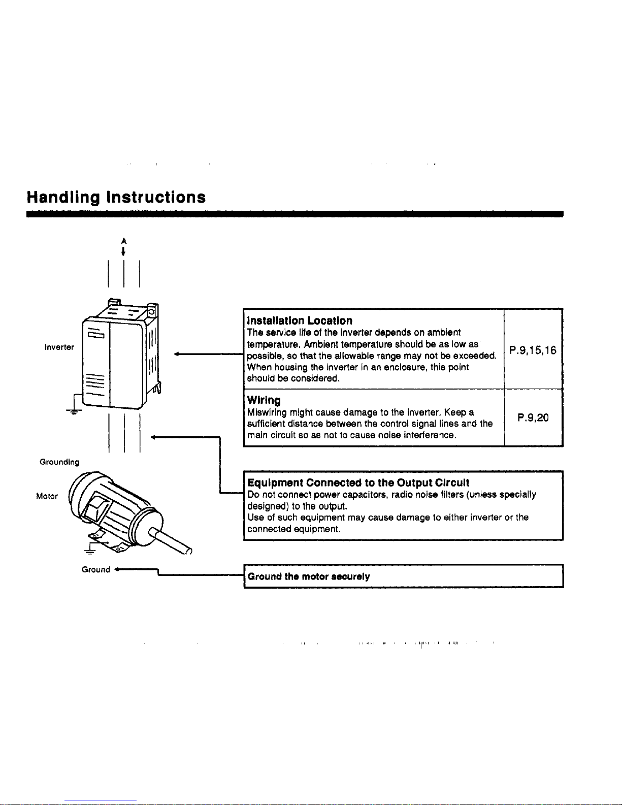
installation Location
The service life
of
the inverter depends
on
ambient
temperature. Ambient temperature should
be
as low as
possible,
so
that the allowable range may
not
be exceeded.
When housing the inverter in an enclosure, this point
should be considered.
Wirlng
Miswiring might cause damage
to
the inverter. Keep a
sufficient distance between the control signal lines and the
main circuit
so
as
not
to
cause
noise
interference.
p.9,,
5,,6
P.9,20
designed)
to
the
output.
Use
of
such equipment may cause damage
to
either inverter or the
Grounding
Motor
Ground the motor securely
1.
PRECAUTIONS
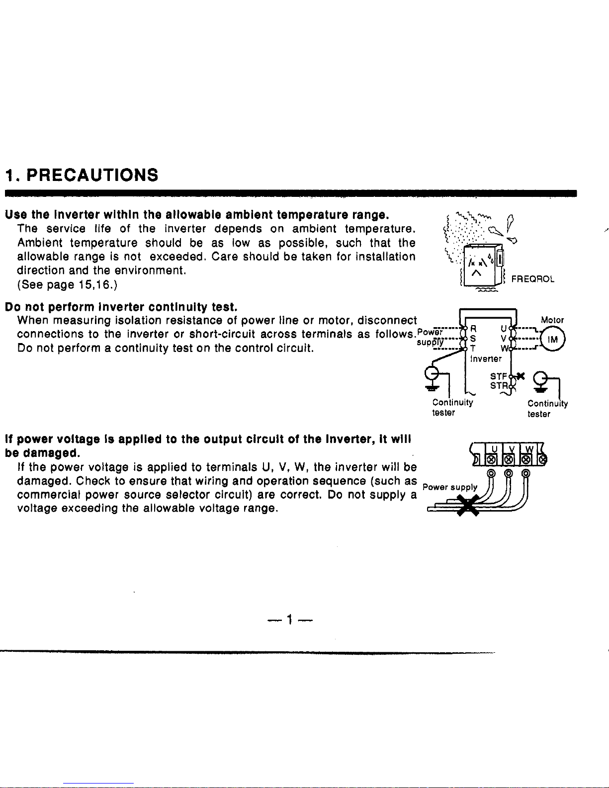
Use
the Inverter wlthln the allowable ambient temperature range.
The service life of the inverter depends on ambient temperature.
Ambient temperature should be as low as possible, such that the
allowable range is not exceeded. Care should be taken for installation
direction and the environment.
(See page
1516.)
--
FREQROL
Do
not perform Inverter contlnulty test.
When measuring isolation resistance
of
power line or motor, disconnect
Motor
connections
to
the inverter
or
short-circuit across terminals as follows.Pow
Do
not perform a continuity test on the control circuit.
Conlinuily Continuity
tester tester
If
power
voltage
Is
applied to the output circuit
of
the Inverter, it will
be damaged.
damaged. Check to ensure that wiring and operation sequence (such as
If
the power voltage is applied to terminals
U,
V,
W,
the inverter will be
commercial power source selector circuit) are correct.
Do
not supply a
voltage exceeding the allowable voltage range.
-1-
I.
0N.OFFI
oN’oFF+.,ON.OFF!
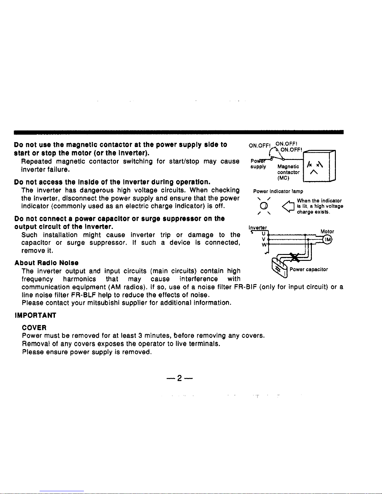
Do
not use the magnetic contactor at the power supply side to
start or stop the motor (or the inverter).
Repeated magnetic contactor switching for startktop may cause
supply
Po~~~n
Magnetic
inverter failure.
contactor
A
The inverter has dangerous high voltage circuits. When checking
indicator (commonly used as an electric charge indicator) is off.
Do
not connect a power capacltor
or
surge suppressor on the
(MC)
Do
not access the inside
of
the inverter during operatlon.
Power indicator lamp
the inverter, disconnect the power supply and ensure that the power
\ /
/\
charge
exisIs.
When
the
indicator
output circuit
of
the inverter.
I
Such installation might cause inverter trip or damage to the
capacitor or surge suppressor.
If
such a device is connected,
remove it.
The inverter output and input circuits (main circuits) contain high
frequency harmonics that may cause interference with
communication equipment
(AM
radios).
If
so,
use of a noise filter FR-BIF (only for input circuit) or a
line noise filter FR-BLF help to reduce the effects of noise.
Please contact your mitsubishi supplier for additional information.
r
About Radio Nolse
I
M
PORT ANT
COVER
Power must be removed for at least 3 minutes, before removing any covers.
Removal
of
any covers exposes the operator to live terminals.
Please ensure power supply is removed.
-2-
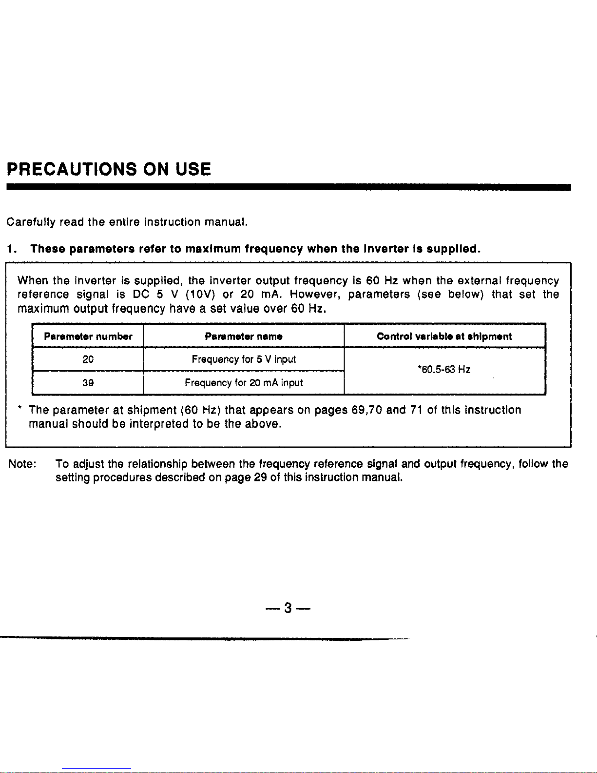
PRECAUTIONS ON USE
Parsmetar number
20
39
Carefully read the entire instruction manual.
Panmeter name
Frequency
for
5
V
input
Frequency
for
20
rnA
input
Control varlabie at shipment
‘60.5-63
HZ
.
1.
These parameters refer to maximum frequency when the Inverter is supplied.
When the inverter is supplied, the inverter output frequency is 60 Hz when the external frequency
reference signal is DC
5
V
(1OV)
or
20
mA.
However, parameters (see below) that set the
maximum output frequency have a set value over
60
Hz.
‘
The parameter at shipment
(60
Hz) that appears
on
pages 69,70 and 71 of this instruction
manual should be interpreted to
be
the above.
Note:
To
adjust the relationship between the frequency reference signal and output frequency, follow the
setting procedures described on page
29
of this instruction manual.
-3-

~~
Inverter
r
(
/’
Frequency reference potentiometer
(voltage signal)
Pr.20
(>
10
2
(0-5Vor0-10
V)
common
,.
5
Frequency reference signal
(current signal)
Pr.39
(
/’
(>
10
2
(0-5Vor0-10
V)
common
,.
5
-b4
(4-20mA)
-4-
I
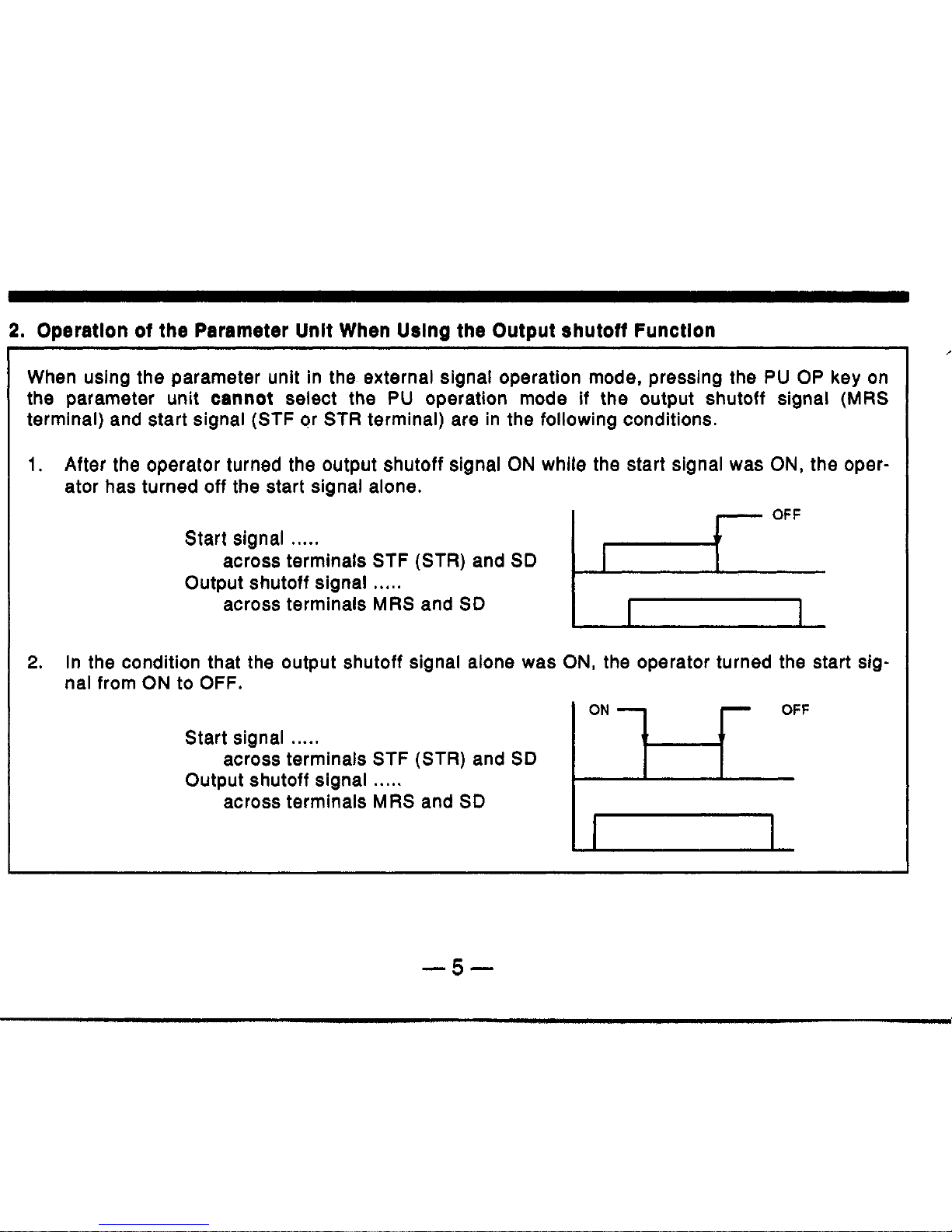
2.
Operation of the Parameter Unit When
Using
the Output shutoff Function
When using the parameter unit in the external signal operation mode, pressing the
PU OP
key on
the parameter unit
cannot
select the
PU
operation mode
if
the output shutoff signal (MRS
terminal) and start signal (STF or STR terminal) are in the following conditions.
1.
After the operator turned the output shutoff signal
ON
while the start signal was
ON,
the oper-
ator has turned off the start signal alone.
Start sianal
.....
I
1
OFF
across terminals STF (STR) and
SD
OutDut shutoff sianal
.....
'across terminals MRS and
SD
In
2.
In the condition that the output shutoff signal alone was
ON,
the operator turned the start sig-
nal from
ON
to OFF.
EF
Start signal
.....
Output shutoff signal
.....
across terminals STF (STR) and
SD
across terminals MRS and
SD
-5-
To
select the
PU
operation
mode:
First, break connection between terminals
MRS
and
SD,
then press the
PU
OP
key.
Note: When the operator has changed the function of terminal
MRS
from ’output shutoff’ to ’second
3.
Attachlng the Front Cover
accelerationldeceleration
time selection’, it is possible to select the
PU
operation mode on the
condition that the start signal is
OFF.
When
attaching the front cover, locate the lower lugs first, into the main cover.
Bring the upper part
of
front cover to the main cover and press firmly.
it will “click” when in the correct position.
-6-
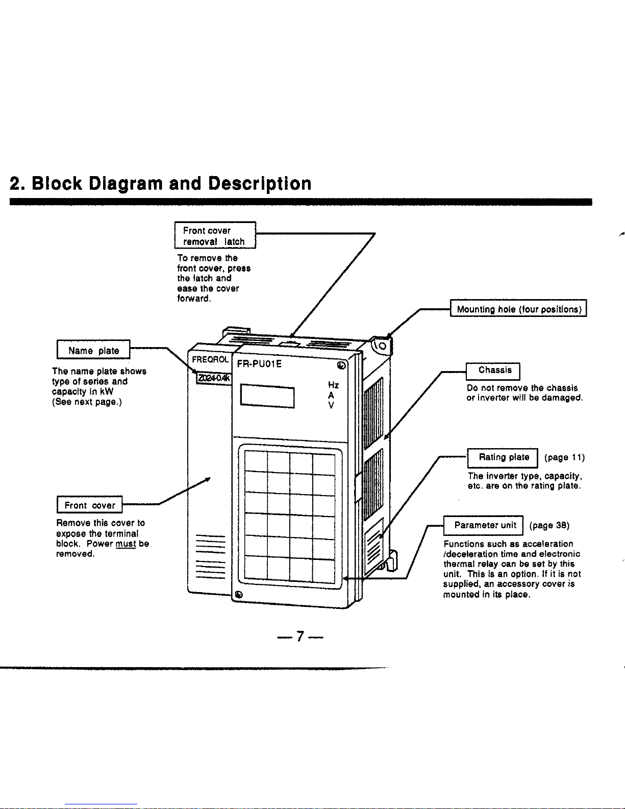
2.
Block Diagram and Description
Front cover
To
remove
the
front cover, press
the latch and
ease the cover
forward.
Name plate
The
name plate
shows
type
of
series and
capacity
in
kW
(See
next page.)
k.
Front cover
Remove this cover
to
expose the terminal
block.
Power
be
removed.
/
mounted
in
its place
w
Mounting
hole
(four positions)
The inverter type, capacity,
etc. are on the rating plate.
supvlied. an accessory cover
is
-7-

2.
Block
Diagram
and
Description
0.1
K
to
3.7K
Model
Size
Inverter
capacity
is
shown
in
kW.
FR-2024-
3.7K
T
I
Applicable
motor
caeacltv
Symbol
-8-
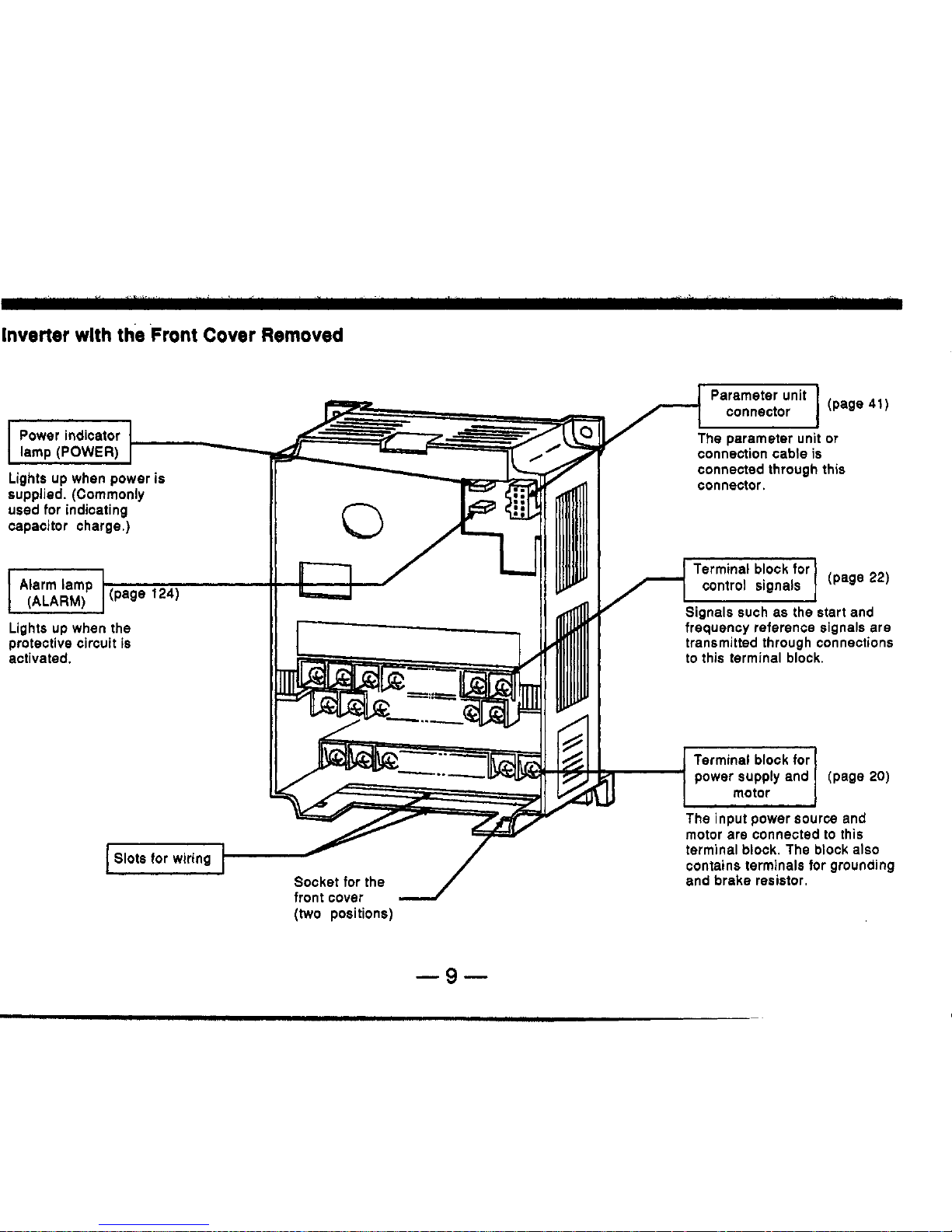
Inverter
wlth the
Front
Cover
Removed
I
1
Power indicator
I
lam0 (POWER)
The parameter unit or
connection cable is
connected through this
Lights up when power is
supplied. (Commonly
used for indicating
capacitor charge.)
11
Lights up when the
protective circuit is
activated.
connector.
Signals such as the start and
frequency reference signals are
transmitted through connections
to this terminal block.
Terminal block for
power supply and (page
20)
motor
J
The
input power source and
motor are connected to this
front cover
1
(two
positions)
-9-
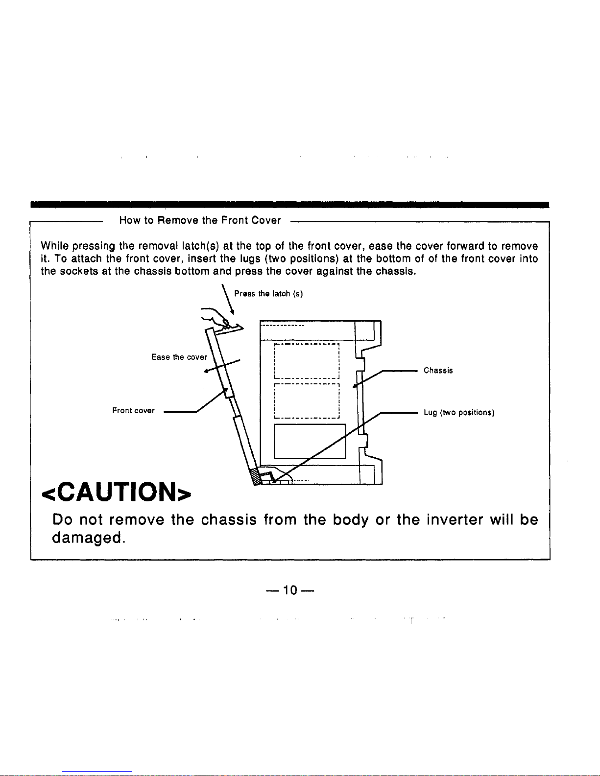
How
to Remove the Front Cover
While pressing the removal latch(s) at the top of the front cover, ease the cover forward to remove
it.
To
attach the front cover, insert the lugs (two positions) at the bottom
of
of the front cover into
the sockets at the chassis bottom and press the cover against the chassis.
\
Press the latch
(8)
Ease the cover
Front cover
b
<CAUTION>
Chassis
Lug
(two
positions)
Do
not remove the chassis from the body or the inverter will be
damaged.
-10-
I
3.
PreDaration before Operation
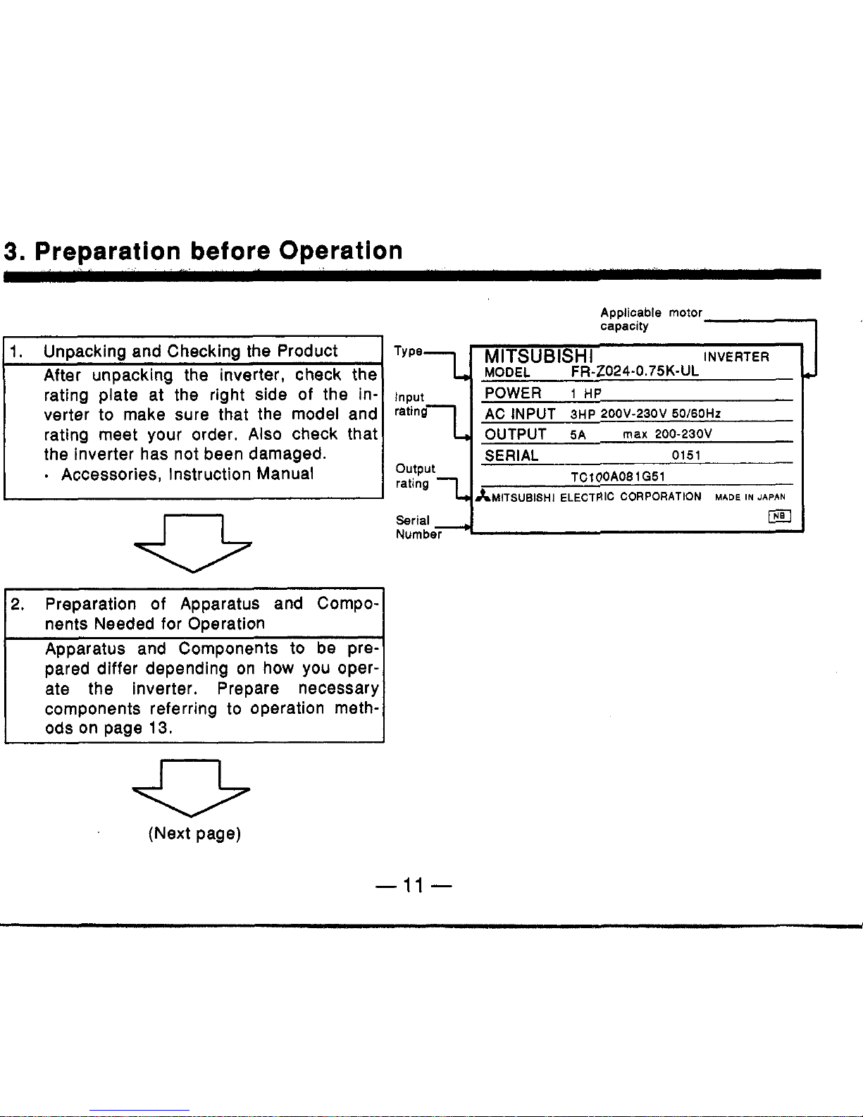
1.
Unpacking and Checking the Product
After unpackina the inverter, check the
rating plate at-the right side of the in-
verter to make sure that the model and
rating meet your order.
Also
check that
the inverter has not been damaged.
.
Accessories, Instruction Manual
n
2.
Preparation of Apparatus and Components Needed for Operation
Apparatus and Components
to
be prepared differ depending on how you operate the inverter. Prepare necessary
components referring
to
operation meth-
ods on page
13.
(Next page)
Applicable
motor
capacity
1-
INVERTER
Type
MlTSUBlSHl
7
MODEL
FR-2024-0.75K-UL
Input
POWER
1
HP
AC
INPUT
3HP 2OOV-230V
50/60Hz
OUTPUT
5A max 200-230V
SERIAL
0151
TC100A08
1051
output
ratina
1
AMITSUBISHI
ELECTRIC
CORPORATION
MADE
IN
JAP~N
I3
-11
-
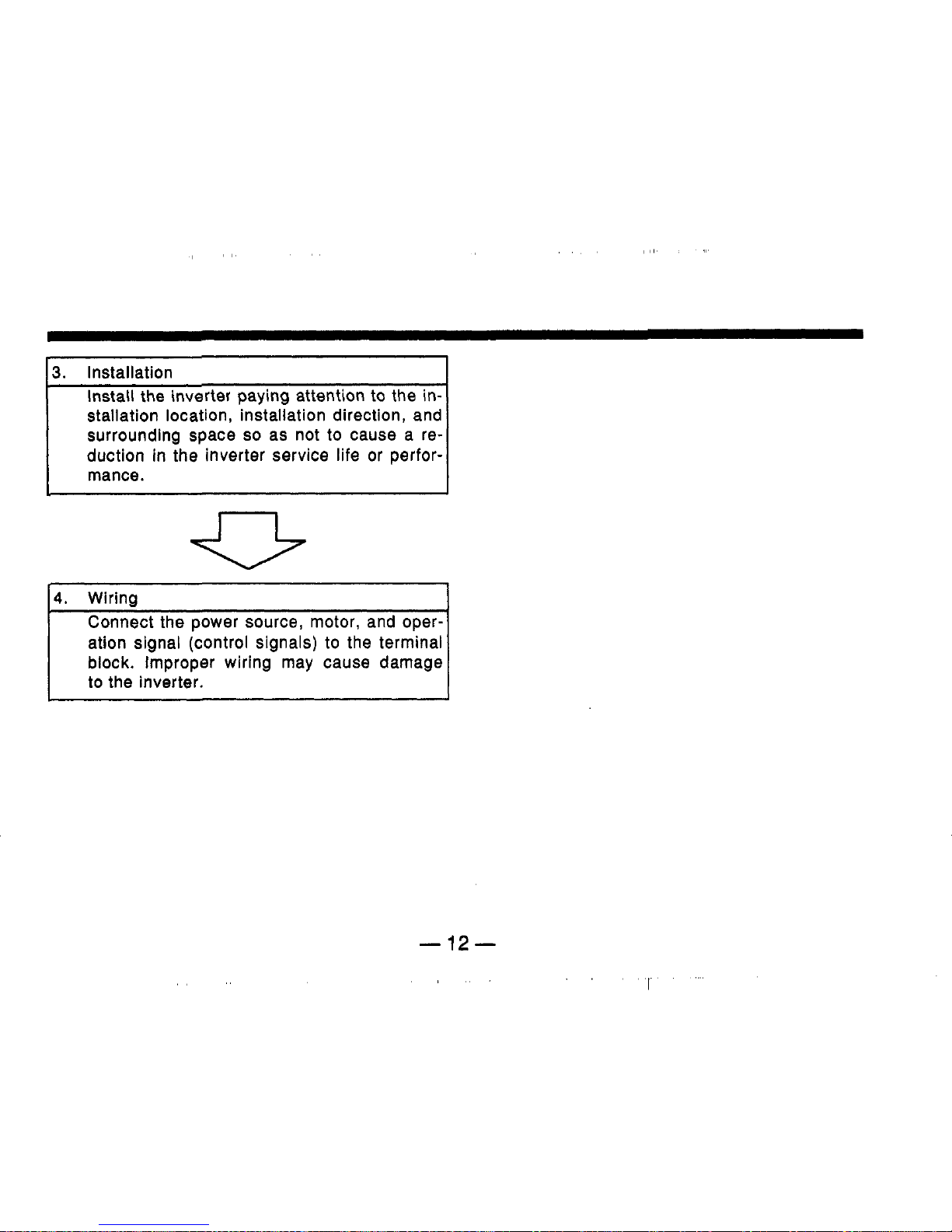
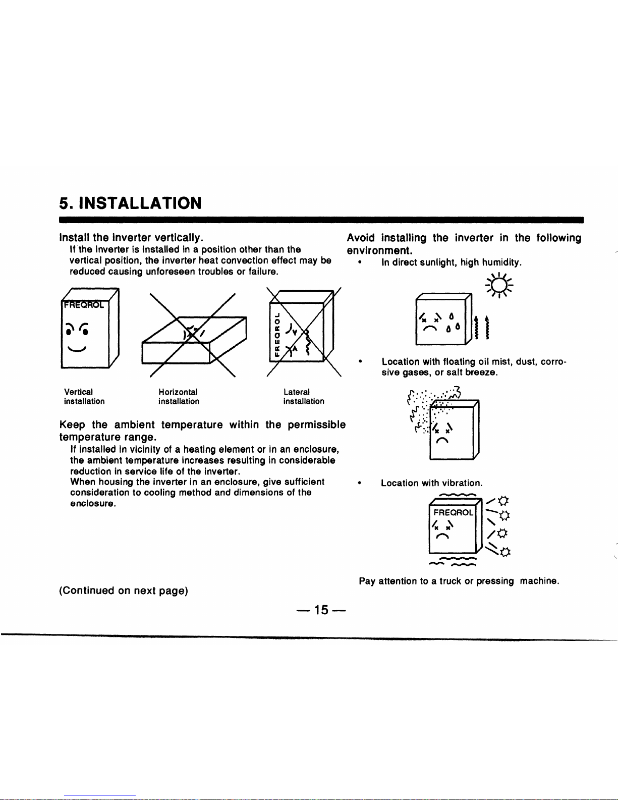
stallation location, installation direction, and
surrounding space
so
as not
to
cause a re-
duction in the inverter service life or perfor-
mance.
~~ ~
4.
Wiring
Connect the power source, motor, and oper-
ation signal (control signals)
to
the terminal
block. Improper wiring may cause damage
to
the inverter.
-12-
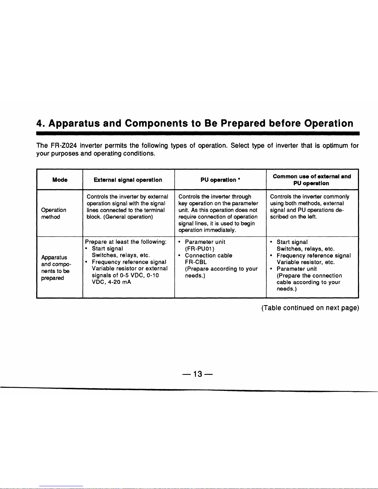
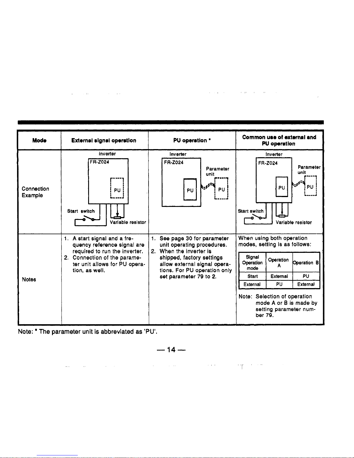
Mode
Connection
Example
Notes
External signal opemtlon
Inverter
!
PU
i
I.
A
start signal and a frequency reference signal are
required
to
run the inverter.
2.
Connection of the parameter unit allows for
PU
opera-
tion, as well.
PU
opsrrtlon
Inverter
FR-Z024
Parameter
unit
r"":
:q
p"
.I
,I
L.--..l
I.
See
page
30
for parameter
unit operating procedures.
?.
When
the
inverter is
shipped, factory settings
allow external signal operations. For PU operation only
set
parameter
79
to
2.
Common
use of
external end
PU
oparatlon
Inverter
I I
FR
-2024
El
Start
switch
When using both operation
modes, setting is as follows:
I
Ex;;d
I
Exteel
I
PU
1
Note: Selection of operation
External
mode A or 0 is made by
setting parameter number
79.
Note:
The
parameter
unit
is
abbreviated
as
'PU'.
-14-
I
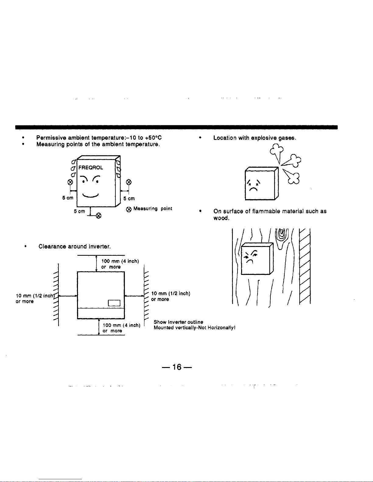
Permissive ambient temperature:-1 0 to
+5OoC
Location with explosive gases.
Measuring points
of
the ambient temperature.
/
0
.
/
/
/
/
/
/
/
10
mm
(112
or more
tTv
Q9
Measuring point
On surface of flammable material such as
wood.
or more
0
0
0
0
0
0
0
/
-0
10
mm
(112
inch)
or
more
inchc-
I
,oo
mm
(4
inch)
’
Show Inverter outline
-
16-
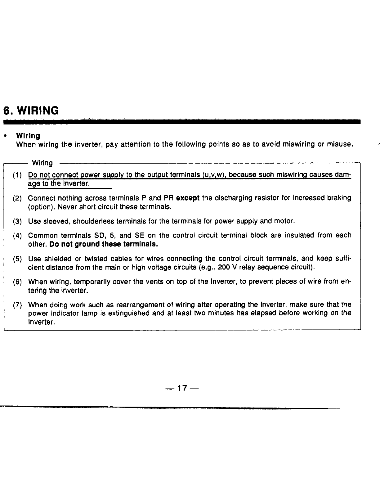
6.
WIRING
Wlrlng
When wiring the inverter, pay attention
to
the following points
so
as
to
avoid miswiring
or
misuse.
-
Wiring
(1)
Do
not connect power supply to the output terminals (u,v,w), because such miswiring causes dam-
aae to the inverter.
(2)
Connect nothing across terminals P and
PR
except
the discharging resistor for increased braking
(option). Never short-circuit these terminals.
(3)
Use sleeved, shoulderless terminals for the terminals for power supply and motor.
(4)
Common terminals
SD,
5,
and
SE
on the control circuit terminal block are insulated from each
other.
Do
not
ground
these
termlnals.
(5)
Use shielded or twisted cables for wires connecting the control circuit terminals, and keep suffi-
cient distance from the main or high voltage circuits (e.g.,
200
V
relay sequence circuit).
(6)
When wiring, temporarily cover the vents on top of the inverter,
to
prevent pieces of wire from en-
tering the inverter.
(7)
When doing work such as rearrangement
of
wiring after operating the inverter, make sure that the
power indicator lamp is extinguished and at least two minutes has elapsed before working on the
inverter.
-
17-
h
-
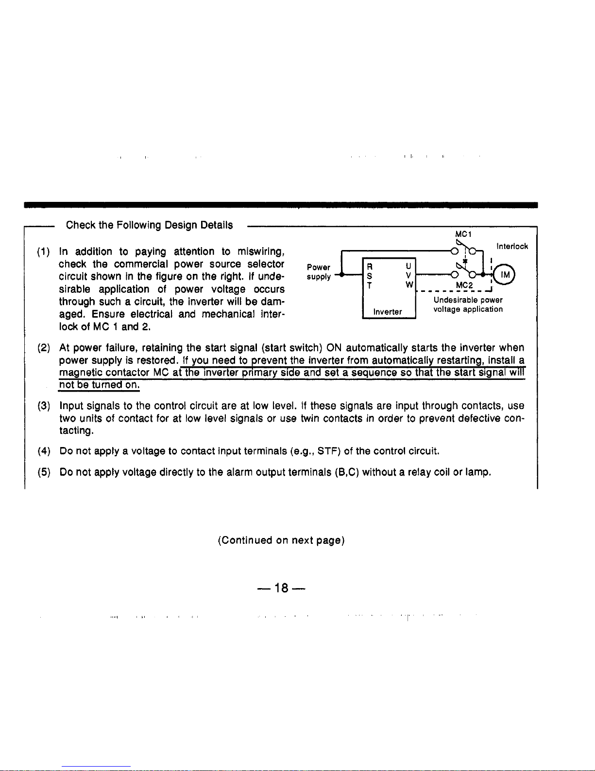
Check the Following Design Details
Interlock
(1)
In addition
to
paying attention
to
miswiring,
check the commercial power source selector
circuit shown In the figure on the right.
If
unde-
sirable application
of
power voltage occurs
aged. Ensure electrical and mechanical interlock of MC
1
and
2.
(2)
At
power failure, retaining the start signal (start switch)
ON
automatically starts the inverter when
Power
supply
W
through such a circuit, the inverter will be dam-
Undesirable power
(3)
Input signals
to
the control circuit are at
low
level.
If
these signals are input through contacts, use
two units of contact for at low level signals or use twin contacts in order
to
prevent defective con-
tacting.
(4)
Do
not apply a voltage
to
contact input terminals (e.g.,
STF)
of
the control circuit.
(5)
Do not apply voltage directly
to
the alarm output terminals (B,C) without a relay coil or lamp.
(Continued on next page)
-18-
h
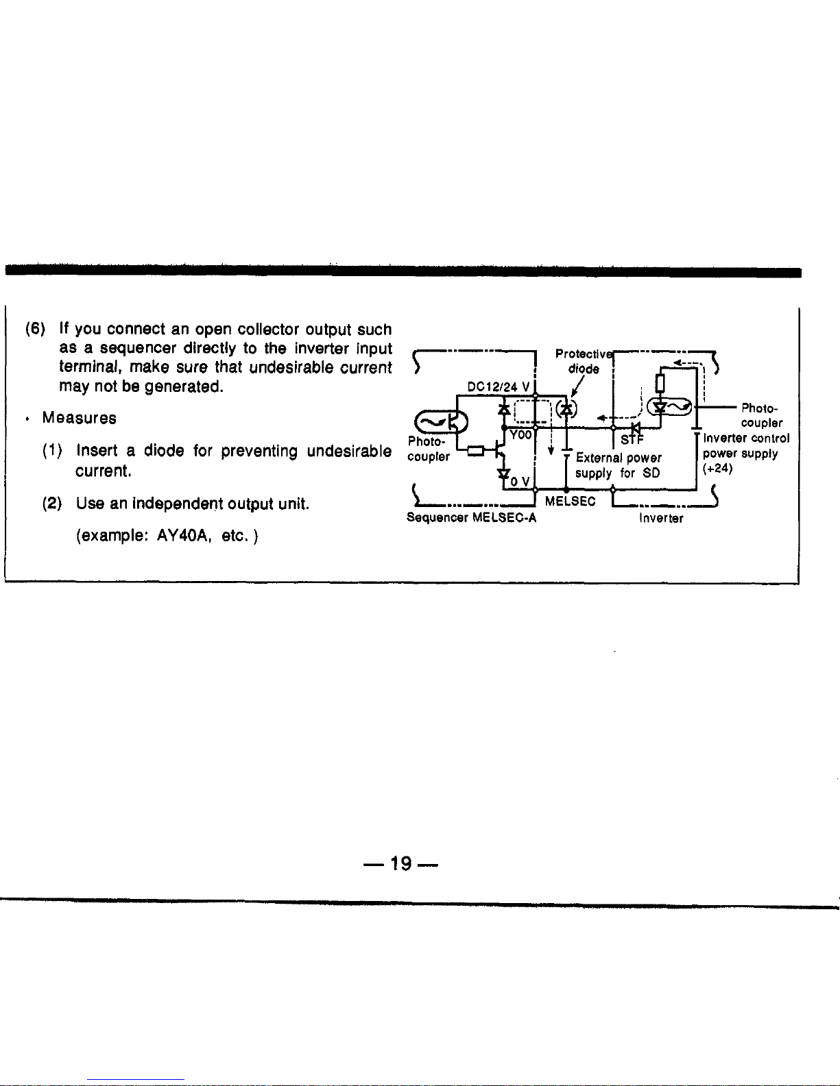
(6)
If
you connect an open collector output such
as a sequencer directly
to
the inverter input
r---.-l
ProtectivT--;-q
terminal, make sure
that
undesirable current
diode
,
n
may not be generated.
e
Measures
(1)
Insert a diode for preventing undesirable
coupler
current.
(2)
Use an independent output unit.
(example:
AY40A,
etc.
)
uv
MELSEC
L..,..
Sequencer
MELSEC-A
Inverter
-19-
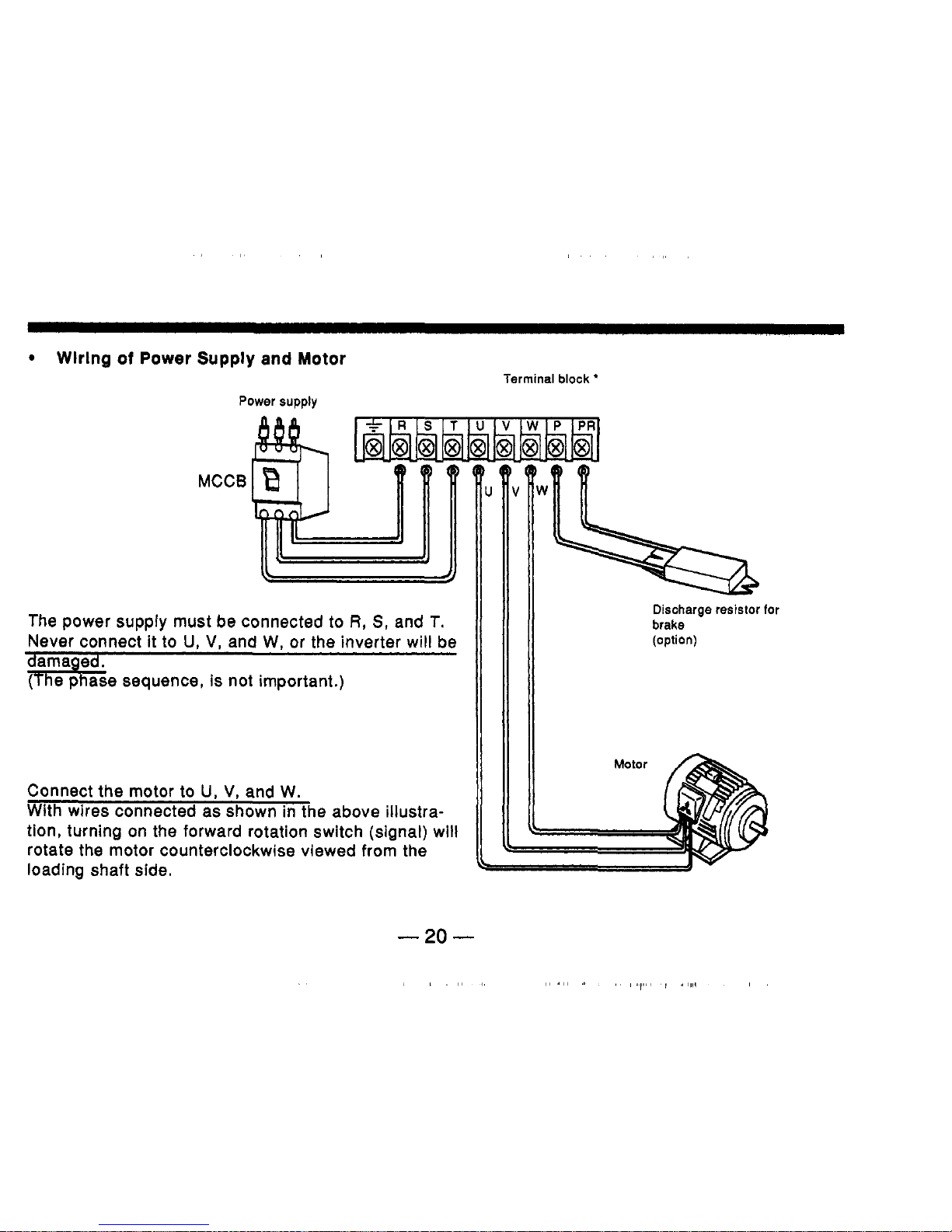
Wlrlng
of
Power
Supply
and
Motor
Terminal
block
'
Power supply
The Dower
su~~lv
must be connected
to
R.
S.
and T.
Never connect'it-to
U,
V,
and W, or the inverter will be
me sequence, is not important.)
Connect the motor to
U,
V,
and W.
With wires connected as shown in the above illustration, turning on the forward rotation switch (signal) will
rotate the motor counterclockwise viewed from the
loading shaft side.
Discharge resistor for
brake
(option)
Notes:
1.
Terminal block
Terminal arrangement
.....
as shown on the previous page.
Screw size
.....
M3.5 screws (FR-Z024-0.1 K to
1.5
K),
M4 screw (FR-Z024-2.2
K,
3.7
K)
Terminal specification
.....
see description of terminal specification (page 120).
2.
Using wire
size
See Selection
of
Peripheral Devices (page 133).
3. The shape
of
terminal block differs according to inverter capacity.
4. Motor overload protection must be provided in accordance with the National Electrical Code.
5.
This drive is not intended to provide overspeed protection.
-21
-
_~_
~-
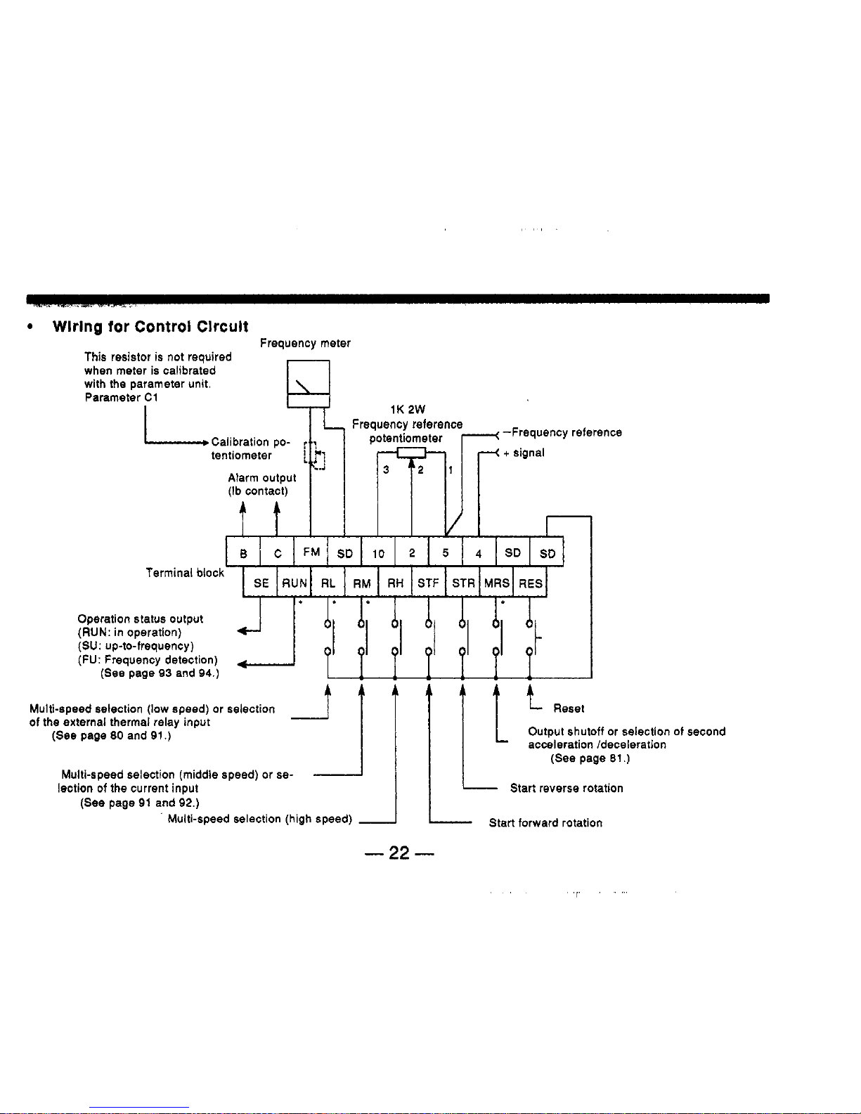
Wlrlng for Control Clrcult
Frequency meter
This resistor
is
not
required
when meter
is
calibrated
with the parameter unit
Parameter C1
1K
2W
-Frequency reference
Frequency reference
ICalibration tentlometer pol potentiometer
Alarm output
(Ib
contact)
Multi.
Terminal
t
t
I I
i
I
VI
B
c
FM
SD
io
2
5
4
SD
SD
block
SE
RUN
RL
RM
RH
STF STR
MRS
RES
I
I
...
I
I1
I
11.1
Operation
status
output
(RUN: in operation)
(SU: up-to-frequency)
(FU: Frequency detection)
(See
page
93
and
94.)
.speed selection (low speed) or selection
f
t t
t
f
t
t
Reset
of
the
external thermai relay input
(See
page
80
and
91.)
Output shutoff or selection of second
acceleration /deceleration
(See
page
81.)
Start reverse rotation
'j
LL
Multi-speed selection (middle speed) or
se-
lection of the current input
(See
page
91
and
92.)
Multi-speed selection (high speed)
Start forward rotation
-22-
Notes:
1.
Terminal block
Terminal arrangement
.....
as shown in the above illustration (two-row).
Screw
size
.....
M3
screws
controlled via the parameter unit.
2.
Input and output specifications for terminals marked with an asterisk
"I
may be
3.
Three terminals named
SD
are connected in the inverter.
-
23
-
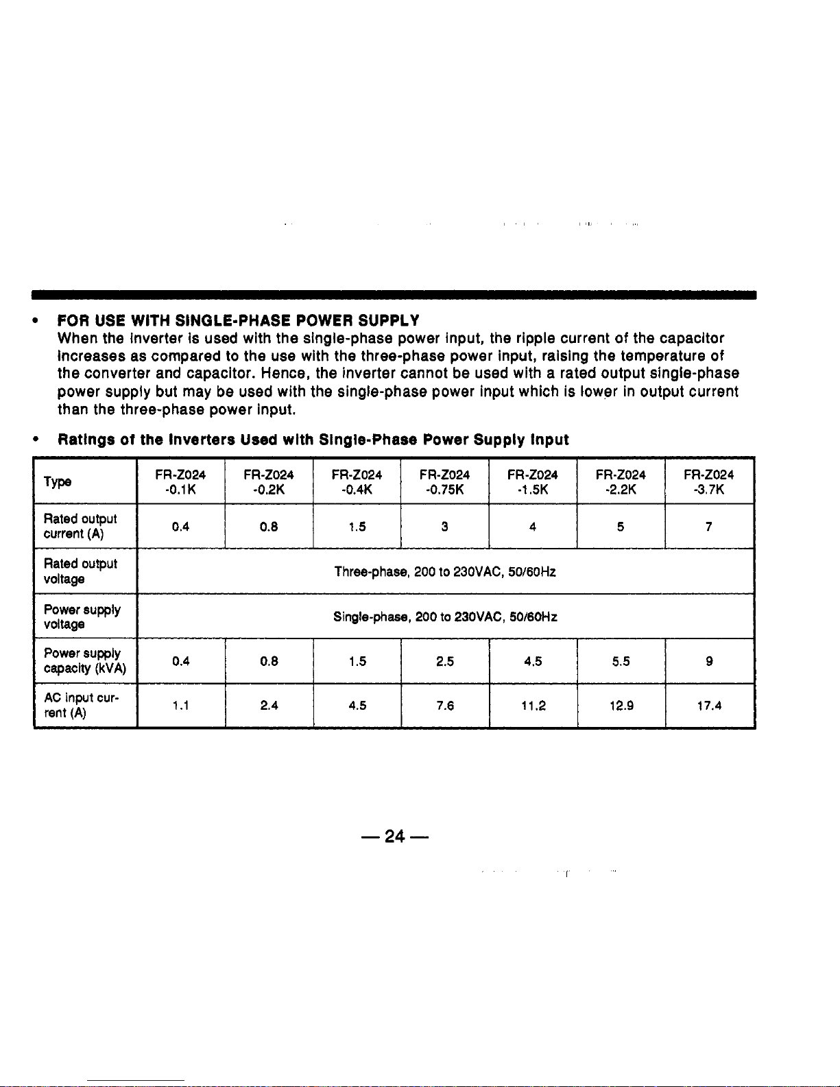
FOR
USE
WITH
SINGLE-PHASE POWER SUPPLY
When the inverter is used with the single-phase power input, the ripple current
of
the capacitor
Increases as compared to the use with the three-phase power input, raising the temperature
of
the converter and capacitor. Hence, the inverter cannot be used with a rated output single-phase
power supply but may be used with the single-phase power input which is lower in output current
than the three-phase power input.
*
FR-2024 FR-2024 FR-2024 FR-2024 FR-Z024 FR-Z024 FR-Z024
Type
-0.1 K -0.2K -0.4K -0.75K -1.5K -2.2K -3.7K
0.4
0.6
1.5
3
4 5 7
Rated output
current
(A)
Rated output
voltage
Power supply
voltage
Power
supply
capacity
(kVA)
0’4
AC
input
cur-
rent
(A)
Three-phase,
200
to
230VAC, 50/60Hz
Single-phase,
200
to
23OVAC,
50/60Hz
0.8
1.5 2.5 4.5 5.5
9
1.1 2.4 4.5 7.6 11.2 12.9 17.4
-24-
r

Notes
on
Use
wlth
Slngle-Phase
Power
Supply
(1)
The single-phase power supply must be connected to the power supply side terminals R and
S
*
of
the inverter.
(2)
The inverter must be used with the power supply
of
sufficient power supply capacity. If the
power supply capacity
Is
small, the output voltage will be varied greatly by the load.
NFB
Single-phase
AC
power
supply
200
to
230V
50
/
60HZ
Motor
Circuit
Example1
-25-

7.
PRE-OPERATION SETTINGS
DC
0-10
V
Principal parameters and descriptions are as
follows.
Set these parameters according to operational
requirements.
-
Setting Method: Use the parameter unit for setting parameters. See page
30
for
descriptions
of
settings.
DC
05
V
Parsmetere
Frequency reference signal
Select
5V
or
1OV
D-crlptlon
Set the frequency reference voltage signals input across termi-
nals
2
and
5.
Set
parameter num-
ber 73
to
1.
0-10
v
4""
Set
parameter nurn-
ber 73
to
0.
I*
The inverter
is
set
as
shown above when
it
I
isshipped.
Note:
Be
sure
to
select
the
0-5
VDC
input if you connect a fre-
auencv reference Dotentiometer (variable resistor).
Related
Functlons
Input selection
5
V/10
V
(pa-
rameter number 73)
(Continued on next page)
-26-
I

Parametem
Maximum output
frequency
Maximum
frequency
Minimum
frequency
Deecrlptlon
Set this parameter when you operate the inverter with a value
other than that set when the inverter is shipped.
See
below for
control variables set at shipment.
If
it is necessary to obtain out-
put frequency higher than
60Hz,
the maximum output trequency
reference must be changed.
‘(Control Variables Set at Shipment)
’
Voltage signal
.....
’
Current signal
.....
PU
operation
.......
60
Hz
at 5 VDC (or
10
VDC)
0
Hz
at 4 mADC,
60
Hz
at
20
mA
up to the maximum frequency of
120
Hz
Set this parameter only when you set the maximum or minimum
-frequency.
Although it is possible to set the maximum frequency within the
range indicated above, the inverter may not operate correctly if
the maximum frequency is set incorrectly.
Note:lf the minimum frequency is set, the motor will run at thc
minimum frequency by just turning the start signal on.
(Continued
on
next
page)
Related
Functlonil
Frequency for input
voltage signal
of
5
V
(parameter number
20)
Frequency for input
current signal
of
20
mA
(parameter number
39)
Maximum frequency at
PU
operation
(parameter number
1)
*
Maximum frequency
(parameter number
1)
*
Minimum frequency
(parameter number
2)
-27-

Electronic thermal
relay
Acceleration/
Deceleration time
Descrlption
Set
the relay in accordance with the rated current
at
the base
speed of the motor.
Note:Operation characteristics, are based on operation with
i
standard squirrel cage motor. They are
not
applicable
ti
special motors.
If
you use a special motor, mount an
extei
nal thermal relay
to
protect your motor. This also appliei
to
mutiple motors.
If
you perform
acceleration/deceleration
operation with a time
other than the value
set
when the inverter
is
shipped, change
the
acceleration/deceleration
time.
Value
set
at shipment: 5 sec.
Note:The
set
value is the time from start
to
the maximum outpu
frequency stated before.
Related
Functions
'
Electronic thermal relay
(parameter number
9)
'
Selection
of
applicable
load
(parameter number
14)
'
External thermal relay
Input selection
(parameter number
46)
*
Acceleration time
'
Deceleration time
(parameter number
7)
(parameter number
8)
Second acceleration
/deceleration time
(parameter number
17)
'
Second deceleration timc
26
(parameter number
47)
-28-

In order to monitor the output status accurately, calibrate the frequency meter before operation. Use of
the parameter unit allows precise adjustment. (See page
64
for calibration procedures.)
-
Changing usage of an inverter (Previouly set up)
Because such an inverter might have parameters set previously according
to
a specific operation, reset
parameters before operation
(reset parameters to values set when the inverter was supplied by
Mitsubishi).
The inverter may be factory reset on the parameter unit. (See page
61
for
initialization.)
Note, however, that the parameters that follow may not be initialized even
if
you all clear
parameters using the parameter unit. Read each control variable and change
it
to
a needed value.
'
Parameter number
20
'frequency for 5 V input signal'
'
Parameter number
39
'frequency for
20
mA input signal'
*
Parameter number
C-2
'frequency reference voltage bias'
'frequency reference voltage gain'
'
Parameter number
C-4
'frequency reference current bias'
'frequency reference current gain'
Parameter number
C-3
Parameter number C-5
-
29
-

8.
OPERATION
Check Points before Swltchlng Power On
e
Check that the power lines are connected to terminals
R,
S,
T.
Also
check that terminals are tight.
Check that the source voltage meets the rated value, and is not exceeding the specification of the
inverter. (See page
11
3
for specifications.)
Check that the setting of the maximum output frequency is within the load (machine) specification
range. (See page
78
for setting conditions.)
-
Check that short-circuit or ground fault do not exist in the output circuit or sequence.
Bask Operating Procedures
After the inverter has been wired, follow the procedures on pages
31,
32
and
33
to check that it operates
correctly.
-30-

-
Operation with External Signals
Example
of
setting frequency
with
a
voltage
signal
Acceleration
Constant
4
speed
I
Switch power on.
I
(The power indicator lamp is lit.)
Slowly turn
the
variable resistor (frequency reference
po-
tentiometer) clockwise
to
the
maximum position.
4
Turn the start switch on. (Short-circuit across terminals
STF and SD or
STR
and SD.)
'
1
Start
I
I
Deceleration
Slowly turn the variable resistor (frequency reference
po-
tentiometer) counterclockwise
to
the maximum position
'2,'3
I
Turn the start switch off. (Open across terminals STF and
SD or
STR
and
SD.)
*
1
stop
h
-31
-

-
Operation with the Parameter Unit
Using the parameter unit.
Switch power on.
(The power indicator lamp is lit.)
I
Selecting the PU
operation mode
Press the PU OP key to select the PU operation mode.
(The indicator lamp next to the PU OP key is lit.)
Enter the frequency value with which you want to operate
the inverter using the numeric keys, then press the WRITE
key, or hold down
or
[El
until desired output frequency
Setting output
frequency
I
i
is reached.
Frequency
change
during
op-
eration
.4
1
Start
and
I
Press the
FWD
or
REV
key.
ation
After pressing the PU OP key, enter the frequency value to
which you want to change, with the numeric keys, then
press theWRlTE key, or hold down
[El
or
sired output frequency is reached.
until the de-
and
stop
Press the STOP key.
'3
-32-
I

Notes:
1.
2.
3.
4.
The inverter will not start
if
both forward and reverse rotation switches are turned on.
If
both
switches are turned on during operation, the inverter will decelerate and stop the motor.
If
the start switch is turned off with the variable resistor turned clockwise to the maximum
position, the inverter will decelerate and stop the motor.
A
high pitch sound is generated just before the motor stops, this is normal. The sound is
generated because the
DC
dynamic brake is in operation.
If
the parameter unit
is
removed from the inverter during operation, normal operation wiii
continue, however, the motor cannot stop, therefore, do not remove the parameter unit
during operation.
,-
F
-33-

Using both External Signals and PU Operatlon
The
2024
inverter permits use of both external signal and PU operations. The details are as
follows:
The start signal is controlled externally, while the output frequency is set on PU.
1.
To
select this configuration, first, set parameter number
79
'operation mode
selection'
to
11.
(See page
51
and
52
for detailed procedures.)
2.
After turning the start switch on, output frequency is set on PU during operation.
(See page
44
and
45
for detailed procedures.)
Notes:
1.
The external frequency reference signal or PU forwardlreverse rotation and stop keys
are not accepted.
2.
The operation mode lamp indicates PU operation. The external signal operation mode
cannot be selected.
3.
If
the start switch is turned on, the inverter
is
not switched
to
the monitoring mode
automatically. To monitor data, press the MONITOR key.
Start switch
I
Inverter
I
-34-

-
The start and multi-speed selection signals are externally controlled, while setting
of
multi-
speed is done by using the
PU.
When the inverter is supplied, setting allows for this configuration.
1.
After turning the start switch
on,
select multi-speed signal needed for operation
(short-circuit terminals
RH-SD,
RM-SD,
or
RL-SD).
2.
Control multi-speed frequency on
PU
during operation.
If
you selet high speed (short-circuit
RH
and
SD),
for
example, a change in value
of
parame-
ter number
4
'third speed setting (high speed)' alters speed during operation. (See page
48
and
49
for detailed operations.)
Note: Control variables of multi-speed other than those in-operation, may be changed during
operation.
Start
switch
Inverter
qM
-
35
-

The output frequency is controlled externally, while start/stop is controlled using.the PU.
1.
To select this configuration, first, set parameter number
79
'operation mode selection'
to
12.
(See page
43
and
44
for de-
tailed operations.)
2.
While inputting output frequency (analog or
multi-speed selection stated above) signal externally,
runlstop is controlled by the FWD/REV and STOP key on
PU.
Notes:
1.
The start terminals (STF, STR) on the inverter are
disabled.
2.
The operation mode lamp indicates PU operation.
The external signal operation mode cannot be selected.
3.
When not in the monitoring mode, the PU display
shows the frequency corresponding
to
the external frequency setting signal. Note that this frequency is not displayed unless the PU OP key is
pressed.
1
i
d
Inverter
10
2
Frequency reference
potentiometer
Current input
1-1
selector Inverter
4.
The inverter may also be started by pressing the FWD or
REV
key
of
the PU, with the
external frequency setting signal set to
0,
and then increasing the frequency setting
signal. (Note that
O.01Hz
is displayed when the set frequency is called by pressing the
PU
OP
key after the FWD or REV key of the PU has been pressed.)
-36-

In-operation Check Points
that the motor rotates in the correct direction.
Check that the motor does not generate unusual noises or vibration.
.
Check that the pointer
of
the frequency meter swings smoothly and correctly.
.
Check
if
the
ALARM
lamp lights, and the inverter stops (inverter trip).
See
page
109
and
1
10
for causes and measures.
h
-37-

9.
How
to Use the Parameter Unit
Parameter unit, model FR-PUOI, is attached to the inverter
(FR-Z
series), or connected
to
the inverter with
the cable (option). The parameter unit permits the operator
to
set (read and write) various control variables
(parameters), and to monitor operational status and alarm messages through its readout.
In this manual, parameter unit
FR-PUO1
is
abbreviated as
'PU'.
-38-

A
Frequency, motor
DISPLAY(READ0UT)
control variables, alarm message,
etc. are displayed by this 7-seg-
ment 4-digit readout.
2nd
or
3rd
group
function
key
(2nd)
Press this key after pressing the
key to read or change (write)
con rot variables for the 2nd group
KEY
after this
SHIFT KEY
Variable (frequency, motor current,
alarm message) to be monitored is
shifted or 3rd group function is
se-
selected by
Iected.
CLEAR KEY
If
incorrect key is pressed during
setting, it can be cancelled by
pressing this key.
9
FUNCTlONlNUMERAL KEYS
-
Parameter
No.
of
1st
group function and
value or frequency can
be
specified.
‘R-PUOI
PARAMETER
MOUNTING SCREW
By loosening two screws, the unit
can be separated from the inverter.
VARIABLE INDICATOR LAMP
Control variable to be monitored (frequency, motor current, etc.) is indicated.
0000
.b
4
4
L
OPERATION MODE KEYS
Operation mode can be selected
from: operation by the parameter
unit, operation by external signals,
readlwrite
of
control variables, monitoring frequency, motor current,
alarm messages.
Note:
The parameter unit is abbreviated as
‘PU’
FREQUENCY ADJUST KEYS
Whilst it is held down, frequency continuously increases or decreases.
OPERATION KEYS
Direction of motor rotation can be
se-
lected and operation can be
stopped.
I
L
I
READlWRlTE KEYS
J
Variable setting can be read
-
39
-

10.
INSTALLATION
The
PU
can be attached directly to the inverter, or connected to the inverter with the approved cable for
remb,te+in#aH$tion~on an enclosure or control with the parameter unit held
in
the opetator’s hands.
It
can be
attached Waonnbetw even when the Inverter is in-operation.
DLrset
Attachment
to
Inverter
Attach PU to the inverter front cover for use (it is electrically connected through the plug and
receptacle).
For
Ffivetters
without
PU,
replace the accessory cover
on
the inverter front cover.
Io
(1
)
Connection
Engage the plug of PU with the inverter receptacle and
gently press the
PU
against
the inverter.
(2)
Securing the PU in position
Lightly tighten
two
screws
to
secure the
PU
in position.
-
40
-

Remote
lnstallatlon
Uslng
the Approved
Cable
Connector
In
addition to attaching PU to the inverter, it
is
possible to install it
to
an enclosure
or
to control it
held by hand for adjustment or maintenance. In this case, use the approved cable (option) to
connect PU and the inverter.
a:::::
Fit
the
guides
to
the
grooves
(1)
Connection
Plug one end
of
the cable into the receptacle
of
inverter, and the other end into PU. When plugging, fit
the guides
to
the grooves. (See the illustration on
the
left.) (Improper connection may damage the inverter.)
The plug on the inverter side should be locked with
screws as shown on the left. On the PU side, secure
the cable
so
that the cable cannot be disconnected by
its own weight.
(2)
Locking
of
Plugs
Note: The extension cable, must
be
a Mitsubishi type, and is available as an option.
-41
-

11.
OUTLINE
OF
FUNCTIONS
Monitoring
Operation status and alarm message can be monitored.
Output frequency
Direction
of
motor rotation
Motor current
Operation mode
Alarm information
See
page
55
for operating
procedures
Setting of control variables
Additional control variables can
be accessed and changed.
See
page
51
and
52
for
operating procedures.
1
-42-
Selection of operation mode
It
is possible
to
select
the
exter-
nal signal operation or
PU
opera-
tion mode.
See
page
43
for operating
procedures.
-I
Motor control
The
motor starts or stop or out-
put frequency can be
set
by key
Operation on
PU.
Jog
operation
is
also
avail-
able.
See
page
51
and
52
for
operating procedures.
I
I

12.
OPERATION
Selecting Operation Mode
How
to
Select
Operation
Mode:
1.
Operating the Inverter with External Signals (External Signal Operation)
When the inverter
is
supplied,
it
is set to this operation mode (when power is turned on, external
signal operation function),
so
it is not necessary
to
select operation mode on PU.
To
select the PU operation mode from the external signal operation mode, press them key.
2.
Operating the Inverter with the Parameter Unit (PU Operation)
Press thep key to select the PU operation mode.
To
select e external signal operation mode from the PU operation mode, press them key.
3.
Operating the Inverter Using both the External and PU Operation Modes
To
control the inverter
using the external and PU operation modes, for example, the start signal is input externally and
output frequency is set on PU, set parameter number
79
to
11
or
12.
Such operation is available
only by this setting. See page
26
for detailed operating procedures.
-43-

Press
the
PU
key.
ul
Press
the
key.
I
1
How
to Set Operation Mode
It is possible to set only one mode
of
operation using either external signal or
PU
oparation.
When power
is
turned on, the set operation mode is selected, and selection
of
other operation
mode is prohibited.
L
I
-44-

Note:
1.
Caution at changing operation mode
Operation mode cannot be changed when the start signal is on
(STF-SD
or
STR-SD is
closed).
In the PU operation mode, do not remove PU during operation. The inverter will stay in
operation even
if
PU is removed. In that case, the operator cannot stop the inverter from
operating the motor.
2.
Caution for removing PU during operation
-45-

OPERATING THE MOTOR
WITH
THE PARAMETER UNIT
The operator can startlstop the motor with PU, without any external frequency reference
potentiometer, or start switch.
JOG
operation is also available with PU. Follow the key operation
below
to
control the motor.
Operating Procedures
Frequency setting
.....
By repeating this procedure during operation, it is possible to vary the
rotation rate.
The increase (or decrease) of frequency is slow initially, after the key is pressed, but increases
as the key is held depressed.
-46-
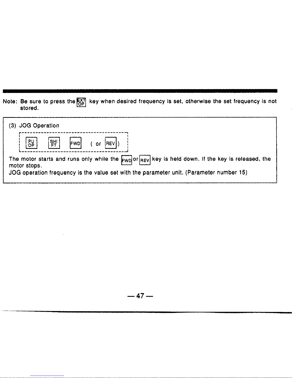
Note: Be sure to press them key when desired frequency
is
set, otherwise the set frequency
is
not
u
stored.
The motor starts and runs only while the
WD
or
REV
key
is
held down. If the key
is
released, the
JOG
operation frequency is the value set with the parameter unit. (Parameter number
15)
motor stops.
El0
h
-47-

To
return to external signal operation, press the
stopped.
(If
the external signal operation cannot be selected, see page
69
and
70.)
key, then press the key after the motor has
(4)
Method to Vary Speed with
PU
during Multi-speed Operation.
Operating procedure
(1)
or
(2)
on page
51
and
52
permits such variation. Note, however, that
pressing the key is unnecessary.
Example of Operation
*
Example where
60
Hz
is set for desired output frequency (from start to
60
Hz)
I
f
cation
Set
to
60
Hz
I
Stari
I
stoa
I
11"''
I
I
I
-48-
I,
.
I.i

*
Example where speed
is
changed during operation
(from
60
Hz
to
30
Hz):
Note: Direct setting of output frequency is impossible while the
MONITOR
mode indicator lamp is lit.
To
set output frequency, press the
PU
key
to
cancel the
MONITOR
mode.
Ll
'
JOG
Operation
cation
i
mlt
oaaX
Xook
Indi-
I
i
I
I
-49-

Notes:
1.
The JOG mode cannot be selected while the motor is in operation. Press the key to
stop the motor, then select the
JOG
mode.
2.
To cancel the JOG mode operation, press the qkey.
3.
Desired frequency and
acceleration/deceleration
ime (acceleration and deceleration times
are the same) for the JOG mode operation can be set by specifying the corresponding
parameter (control variable). (See page
90.)
When the inverter is shipped, the JOG frequency and acceleration/ deceleration time are set
to
5
Hz
and
0.5
sec., respectively (it takes
0.04
sec. for increase of frequency up to
5
Hz).
4.
If
the motor does not start, check the starting frequency.
*
When the motor is started by pressing the start key
(m
orm), the MONITOR mode is
key
automatically selected and output frequency is displayed.
While the inverter output
is
on (motor in rotation), the mode indicator lamp just above the
flickers (the same occurs during
DC
dynamic brake operation).
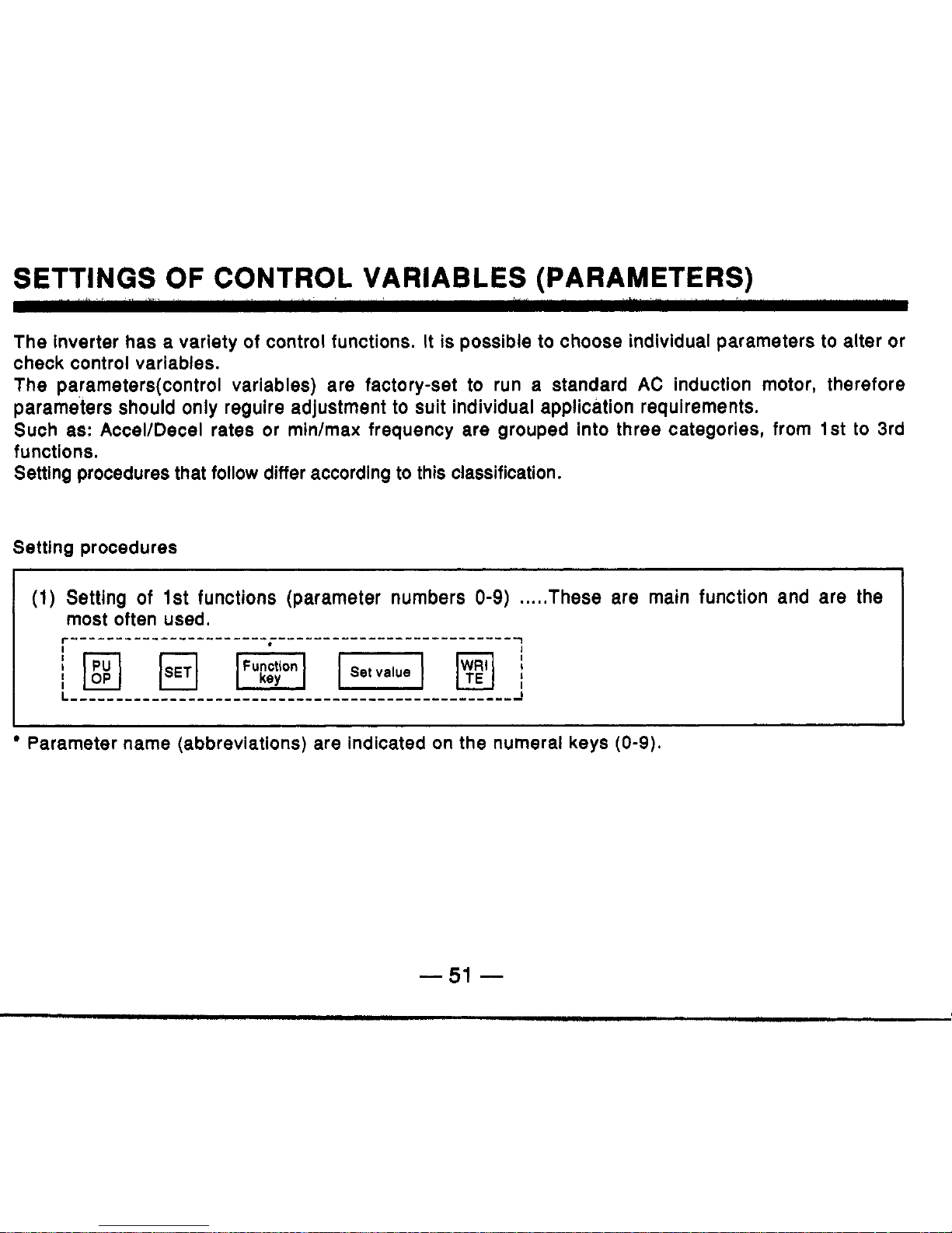
SETTINGS
OF
CONTROL VARIABLES (PARAMETERS)
The inverter has a variety of control functions. It is possible
to
choose individual parameters
to
alter or
check control variables.
The parameters(contro1 variables) are factory-set
to
run a standard
AC
induction motor, therefore
parameters should only reguire adjustment
to
suit
individual application requirements.
Such as: AcceVDecel rates or min/max frequency are grouped into three categories, from
1st
to
3rd
functions.
Setting procedures that follow differ according
to
this classification.
Setting procedures
(1)
Setting of
1st
functions (parameter numbers
0-9)
.....
These are main function and are the
most often used.
r-------I------------I------~----------------------
Parameter name (abbreviations) are indicated on the numeral keys
(0-9).
-551
-

(2)
Setting of 2nd functions (parameter numbers
lo-)
.....
These are used
in
advanced
applications.
(3) Setting of 3rd functions
.....
Calibration
*'
Desired parameter may be called by pressing theB key several times. See page
49
for details.
In the above procedure, press the
READ
key instead
of
the
To
read a set value:
key without entering
a
set value.
(Example)
p]
(The case of 2nd function)
To end or cancel settings:
To control the motor with
PU
at the middle of setting, or when settlng is complete, press the key.
-52-

Examples
of
Operatlon
(1)
Setting of 1st Function (acceleration time setting)
.....
To
change from 5 sec. to
10
sec.
Key
Indi-
cation
h
Write
Solsotton
of
Settlng
of
Read
premnt
Change
to
1st
tunctlon eccelontlon time
value
10
Sec.
lzJ
mm
pJ
ml
Alternate
-1g;z
lpl.11
W]
rr-pTq
*
0
;.:
0
;.,
/ov
(5
sec.)
(1Osec)
Initial setting
Note:
When another
1st
function is
to
be set after setting a
1st
function, the new desired arameter
can be called by
just
pressing the corresponding parameter key,
so
repressing theb key
is
unnecessary.
-53-

(2)
Setting of 2nd function (frequency reference for
JOG
operation)
.....
To
change from
5
Hz
to
10
Hz:
Setting
of
2nd
funct'on
Write
Of
Read present Change to
value
10
Hz
frequency
for
JOG
operation
Indi-
cation
Note:
1.
A
dot is placed after
,!D
,-when the 2nd function is selected, ex.
(
i-7
,-.,)
key is unnecessary.
2.
When another 2nd function is to be set after setting a 2nd function, the new desired
parameter can be called by just pressing the
2nd
key and specifying the parameter number,
so
repressing the
0
*
If
changing parameter or reading is impossible:
See page
71
when an error message is displayed and a new value cannot be written.
-54-

MONITOR
Output frequency
Output current
Conditions
of
load such as output frequency and motor power, and information about activated
protectlve function at occurrence of an abnormality can be monitored
with
PU
(by
segment display and
LED
lamps).
Type
of
Yonltored
lnlotmatlon
Hz
Readout and
In the MONITOR mode shift the display information with the
variable indicator
key
A
lamp
I
I
monnored
1
Unlt
I
lndlcator devlce
1
Dleplay/operetlon/se~lng
In
brief,
etc.
Information
I
Switched from the monitoring of the output frequency when
I
the function number
37
is
set.
I
Engineering Display Unit
I
I
Indicator
lamp
I
I
Direction
of
rotation
I
-
IVaJa;ble
indicator
The lamp is lit at forward rotation and is flickering at reverse
I
rotation.
In-operation Operation mode
indicator lamps
External signaVPU operation
MONITOR
mode
Setting mode
The lamp above the operation mode key corresponding
to
the
selected mode is lit. When the motor is running, the lamp
flickers, when stopping, the lamp is just
lit.
I
JOG
mode
I
-
IReadout
I
If
the
JOG
meration mode is selected,
'JOG'
is
displayed.
I
-55-

Readout (7-segment 4-digit
LED)
\
Variable indicator lamps
Control variable
to
be
monitored is
/-
indicated.
All
lamps are turned
off
when
alarm information is on
the
readout.
Parameter Unit
Operation mode indicator
/lamps
/
When an operation mode
key
is
pressed,
the
corresponding lamp is
lit.
Operation mode
keys
-56-

lndlcator
Lamp
in
the
MONITOR
Mode
In
this manual, the variable indicator lamps are described
in
the following layout.
;e:
is
a
"lit"
lamp, and
0
is an extinguished lamp. The same is applicable
to
the operation mode indicator
lamps.
lndlcatlon
0
Hz
0
A
0
V
Descriptlon
Frequency is displayed.
Motor current is displayed.
Not used.
If
the stall prevention function is activated during MONITOR mode, all
MODE
lamps except that selected flicker.
If
the motor
is
in forward
or
reverse rotation, these lamps are
lit
or
flicker, respectively.
Note
1:
The engineering display unit is displayed when the function number
37
is set to any value
other than
0.
-57-

Example
of
Operation
*
Output frequency, motor current (constant), alarm condition (checking)
-
Output frequency
I
(60
Hz)
Motor
current
c
0
HZ
ov
A
/'
'do
0
0
/'
(6.5
A)
Alarm
condltlon
(Returns
to
the latest alarm.)
Note:
By pressing the
SHIFT
key when an alarm condition is indicated, the output frequency at the
time of the alarm
L7
IS
isp ayed.
-
To
check
the
stored alarm information:
Up
to
four alarm codes are stored.
To
check them follow the procedure below in the above alarm
condition displaying status.
I
I
................
-
Fl-
~I-~IREAD------*/
READ
/
................
-
2nd latest alarm 3rd latest alarm Oldest alarm (Returns
to
the latest alarm.)
-558-
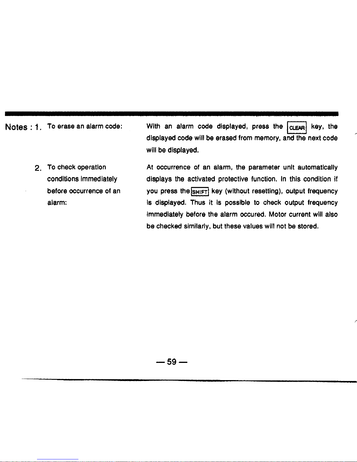
Notes
:
1.
To erase an alarm code:
With an alarm code displayed, press the
@
key, the
displayed code will be erased from memory, and the next code
will
be
displayed.
A
2.
To
check operatlon
At Occurrence of an alarm, the parameter unit automatically
displays the activated protective function. In this condition if
you press them key (without resetting), output frequency
is
displayed. Thus it is possible to check output frequency
immediately before the alarm Occured. Motor current will also
be checked similarly, but these values will not be stored.
conditions immediately
before Occurrence of an
alarm:
-59-

Alarm
Dlsplay
If
failure occurs
during
operation of
the
inverter,
an
alarm
code
is
automatically displayed
on
the
PU
readout
as
follows
(See
page
124
for details):
DIaplay
I-
/
c
1-1
c
Code
Dwrlption
EOC1 Inverter output current exceeded the overcurrent limit during acceleration.
I
E
2:
I
EOC2 I inverter output current exceeded the overcurrent limit during constant-speed operation.
f-
1:
I-/
1-1 1-1
I I-
11
1- (-1
1-1
I-
1- I 11
I
1,’
I-
I-/ I-
1-
I I 11
c
1-
c
L
.
-/
L
I-
-?
1
EOC3
I
Inverter output current exceeded the overcurrent limit during deceleration.
I
L
1-1
c
EOVT
Braking regenerative power from motor exceeded the regenerative overvoltage limit.
Electronic thermal relay in the inverter was activated (current is below
150%
of preset
current).
Electronic thermal relay in the inverter was activated (current is over 150%
of
preset
current).
Brake transistor in the inverter fault detection. E. BE
c
1
I
-
60
-
I,

Dlaplry
/:
I7
/-I
I-
1-
1-1
I
I
/
1:
1-1
I I-
Stall prevention function was activated during constant-speed operation and
stopped
the
I
1-
1-1
1-
I
Code
De6crlption
EOHT
External thermal relay was activated.
I
E
.
a’1
1
E.PE
I
Data memory in the inverter and corresponding
to
parameter number
is
corrupted,
I
L
11
I7
I:/
I-
1-
1-1
I
I
EOPT
Indicates that the retry function has been activated or any error other than the error selected
by
the retry selection has occurred and
stopped
the inverter.
-61
-

Characters Appearlng In Readout
The alphanumeric which appear in the readout are listed below.
Letter
Dlsplay
-
62
-
I

~~~~~~~~~~
It is possible to reset (initialize) control variables to those set when the inverter is supplied except for
some parameters. This procedure is called ’ALL CLEAR’.
Operating procedure
~~~~
Parameter number
‘20
‘39
c-
1
c
-2
c-3
c-4
c-5
When writing is complete,
-1
is displayed and flickers.
~~~~ ~ ~ ~
Parameter name
Frequency for
5
V
input signal
Frequency for
20
mA input signal
Frequency meter calibration
Frequency reference voltage bias
Frequency reference voltage gain
Frequency reference current bias
Frequency reference current gain
Note : The following control variables are
not
initialized through the all clear operation stated above.
*These control variables set the maximum output frequency using external signal operation, and also
are reference frequencies for
acceleration/deceleration
time. After carrying out ALL CLEAR, check
these values and reset to optimum values.
-
63
-

FREQUENCY METER CALIBRATION
It
is possible
to
calibrate any frequency meter connected
to
the frequency meter connection terminals,
FM
and
SD
on the inverter, by operating the PU.
If
it is a digital indicator, pulse train signal frequency
may be adjusted.
Preparation
(1)
Connect the frequency meter across terminals
FM
and
SD
on
the inverter. (Pay
attention
to
polarity matching.)
(2)
If
a calibration resistor has already been connected, remove it or adjust it
so
that its
resistance reads zero.
Inverter
Frequency meter
Calibration
resistor
-
64
-

Operatlng Procedure
1.
Operate
PU
to set the
frequency for meter fullscale reading.
(*)
2.
Select the meter calibration
mode.
3.
Calibrate the meter.
(Set to
60
Hz when the
inverter is shipped.)
of the frequency meter,
When the meter has been calibrated, press the
WRI
key.
'The motor need not be connected.
Note:
If
a signal relative to magnitude of motor current is to be output from the
FM
terminal (see page
95),
install a calibration resistor at the position shown on the previous page. Output of the
FM
terminal is not adjusted with the above procedure.
-65-

ADJUSTING BIAS AND GAIN
FOR
FREQUENCY REFERENCE
SIGNAL
Using 'bias' and 'gain', the operator can adjust the relationship between output frequency and
leference input signals such as
0-5
VDC,
0-1
0
VDC, or
4-20
mA DC, which set the output frequency.
This function is classified as 3rd function and is set through the procedure that follows:
SETTI
NO
PROCEDURE
r
.....(
Frequency meter calibration mode C-1)
lwmp-lpJ7
,..Bias setting for frequency
reference voltage ((3-2)
1'
1
I.
I
...
Gain setting
for
frequency
reference voltage
(C-3)
...
Bias setting for frequency
reference current
(C-4)
..Gain setting for frequency
reference current
(C-5)
-
66
-

Example
of
Adjustment
-
Bias setting for frequency reference voltage
.....
when the reference voltage
is
0
V,
the output
frequency will be
10
Hz.
-
Output frequency
60Hz
I
F
-67-

Note: Setting should be made with voltage across the frequency reference input terminals
2
and 5 using 5 V
(or
10
V)
or with input lines disconnected. (When setting characteristics
shown in the illustration on the previous page.)
If
a voltage is being applied, output frequency relative to that voltage is set. In the above
procedure, for example,
if
1
V
is being applied across terminals 2 and
5,
output
characteristics become as shown in the illustration below (solid line).
10
Hz
If
you want to set 0 Hz
against
1
V
/?-
,
input, set 0 Hz
in the above procedure.
.A
I
0
1'v
5'v
-68-

CAUTIONS FOR PU OPERATION
Pay attention to the following points
so
as to avoid incorrect setting or entry of a wrong value during
PU operation.
Operation
Motor control
by PU Operation
Cautlona
Becomes effective only after pressing the
PU
key.
When PU
is
in the monitcr mode (when the indicator lamp above the MONITOR key is lit),
setting the
ou
ut
frequency is impossible.
Press the
PU
key to leave the monitor mode and enter a new value.
An error indication (Err.) will be displayed, or the value you entered will not
be
written under
the conditions that follow
:
(1)
When
you
have entered a value exceeding the maximum or minimum frequency
(setting value for parameter number
1
or
2)
:
la
LJ
(2)
When prohibition of parameter entry is effective (parameter number
77
is set
to
1)
;
(3)
When PU is in the external signal operation mode (the indicator lamp above the
(4)
When PU is in the monitor mode (stated above). (Note, however, step setting is
possible.)
JOG Operation
(1)
(2)
key is lit)
:
M
The JOG Operation is not available when the motor is running.First, stop the motor
to
perform the JOG Operation.
If
the motor does
not
start, check whether the JOG Operation frequency is lower than
the start frequency (parameter number
13).
-69-

Opmtlon
Writing values
Writing values
Ceutlonr
1.
Writing is effective only when PU is in the PU Operation mode, accordingly,
it
is ineffective
in the external signal Operation mode. (Set values can
be
read in either mode.)
Writing is impossible when the motor is running. First, stop the motor to write values. The
following parameters, however, may
be
written even when the motor is running.
(1)
Multi-speed setting (speed
1-7)
......
Parameters number
4-6, 24-27
(2)
PWM mode
......
parameter number
10
(only in the
PU
Operation mode)
Setting values cannot
be
written under the conditions that follow (an error message will
be
displayed)
:
(1)
(2)
(3)
(4)
(5)
(6)
When an error message is displayed, press the[E]key, or repeat the procedures from
the first sten
2.
3.
When
PU
is in the external signal Operation mode;
When the motor is running (except the above
two
parameters):
When prohibition of parameter entry is effective;
When a number not on the parameter list
is
selected:
When a value exceeding the setting range
i5
entered;
When a value exceeding the maximum or minimum frequency is set.
1
-
70
-
I.1

Operation
I
Cautlonr
Reading
values
Monitor
1.
It
is possible
to
read the
set
values for the
1st
and 2nd functions in both PU and external
Operation modes.
In addition, reading is possible
if
the motor is running.
Reading the
set
values for the 3rd functions is possible only when the inverter is in PU
Operation mode.
When the Operator uses the PU
to
control the motor, pressing the start key (FWD or
REV)
after setting frequency automatically
selects
the
monitor mode.
2.
1.
Common -Operation
Maximum number of
digits stored and the
decimal point.
mode.
Selecting PU or external signal Operation
Pressing the
PU
key (or
rn
key) is not allowed for mode change under the conditions
(1)
(2)
(3)
Switching
on
the power of the inverter after switching it off or resetting (across terminals
RES and
SD)
the external Operation mode. (Initial setting)
The maximum number
of
digits for entry
is
four.
If
this
is
exceeded, the first digit is
disregarded. (Example
:
Pressing 12345 will
be
set
as 2345.)
Pressing.
1
for
0.1,
as is done for a calculator, is regarded as
1,
and the decimal point
will
be
disreaarded.
Do
not
omit
a
0.
that follow
:
mm
When the motor is running
;
When the start signal (across terminals
STF
and
SD
or
STR
and
SD)
for the external
signal Operation
is
ON.
When Operation mode (parameter number
79)
is
set
to
PU operation or external
signal Operation.
-71
-

13.
DETAILS
OF
EACH PARAMETER
PARAMETER LIST
-72-
I'

Parameter
No.
initial eettttlng
page:
Parameter
Setting
range
1
18
I
High-speedmaximum frequency
1
120-360Hz
I
120Hz
1
78
16
17
I
19
I
Base frequency voltage
I
Oto500V,
9999
I
9999
I
84
Jog acceieration/deceleration time
0,
0.1-3600
S~C.
0.5
sec.
90
2nd
acceIeratiotVdeceleration
time
0,
0.1-3600 sec.,
9999 9999
81
20
21
Frequency a
5
V
input voltage 1-360 HZ 60 Hz 78
Stall prevention
level
0-200%
150% 88
2nd
function
*24 Multi-speed setting (speed 4) 0-360
HZ,
9999 9999
Multi-speed setting (speed
5)
0-360 Hz,
9999 9999
*25
‘26
Multi-speed setting (speed 6) 0-360
Hz,
9999 9999
*27 Multi-speed setting (speed 7) 0-360 Hz,
9999 9999
.
91
h
29
37
Acceleration/deceleration
pattern selection
0,
1,2
0
82
Engineering display unit display
0,
2,
4,
6, 8, 10,
11
to
9998
0
101
39
42
Frequency at 20
mA
input 1-360 HZ
60
Hz 78
Up-to-frequency sensitivity
1-1
00%
1
0%
94

Parameter
No.
43
Parameter Setting range lnltlal setting Refer
to
page:
Output frequency detection 0.5-360
HZ
6
Hz
44
-74-
94
0.5-360
Hz,
9999 9999
Output frequency detection at reverse
rotation
I
53
69
70
I
72
Retry execution count display erase
1
0
0 100
Parameter set by the manufacturer.
Must
not be
set.
FM
output terminal function selection
0,
1
0
95
Current monitoring output gain 0-200%
150%

I
ParameterNo.
I
73
74
Parameter
5
V/10
V
input selection
0,
1
0
77
Current input selection
0%
1
0
92
I
Setting range
1
initial setting
I
2nd
function
75
Reset selection
0,
1
0
92
Output signal selection
0,1,2
0
93
79
Operation mode selection
0,
1,2,
11, 12
0
83
-
76
Selection
of
prohibition
of
parameter
I
77
I
writing
I
O
Ig7
-
75
-

Notes
:
1.
2.
3.
4.
Set values differ depending on inverter capacity.
For parameters marked with a star, it is possible
to
change set values during operation. (Initial
setting)
Minimum setting step
.
Frequency
.......................
0.01 Hz.
Note, however,
if
frequency is
100
Hz
or
higher, the
minimum setting step is
0.1
Hz.
.
Time
.................................
0.1
seconds. Note, however,
if
0
is entered,
0.04
seconds is set.
.
Current
............................
0.1
A
.
Yo
......................................
1%
The set value of
9999
indicates that "the function is inactive."
-76-
I

SELECTING FREQUENCY REFERENCE SIQNAL
(5
VHO
V)
Set
value
1
It is possible
to
switch the input (terminal
2)
specification
according
to
the frequency reference voltage signal.
When you input
0-10
VDC,
be sure to select appropriately.
I
i
For
0-1
0
VDC
input
I
1
For
0-5
VDC
input
(initial
setting)
Set
value
0
I
0-5
VDC
0-10
VDC
common
Frequency reference
potentiometer
10
(5
V
only)
-
77
-

MAXIMUM
OUTPUT
FREQUENCY
SETTINO
t
It
is possible
to
set frequency for a
VDC) or
20
mA from external equipment.
E.
fml
------------
0
fm2
------
-----
frequency
frequency reference signal of 5 VDC (or
10
G
Accordingly, this is the maximum output
$
frequency in the external signal operation
;
2
mode.
Several
accelerationldeceleration
times can
2
be set for JOG operation
or
multispeed
,O
setting
is
the time (ramp) taken for
acceleration
or
deceleration up to the
FreqJenCy reference
5
V(10
V)
20
maximum frequency.
signal mA
<initial Setting>
*
Voltage signal
.....
60
Hz
at 5 VDC (or
10
VDC)
Current signal
.....
0
Hz
at 4 mA DC,
60
Hz
at
20
mA DC
*
PU
operation
.....
Up to the maximum frequency of
120
Hz
Note:
The set maximum frequency changes automatically
if
you change setting of 'gain for
frequency reference voltage signal' or 'gain for frequency reference current signal'
included in the 3rd functions (see page
43).
Since this function has the same priority
level as that of 3rd function (C-3, C-5), priority is given to the latest set function.
Outpu1
P-J
range
This is
to
be set when running at
120
Hz
or higher. The maximum frequency, parameter number
1
of the
1st
function is automatically updated
to
this frequency.
-778-
I

SETTINO THE FREQUENCY
LIMIT
FUNCTION
Max. limit frequency
Output frequency can be changed to desired
maximum andlor minimum frequency.
Min.
limit frequency
setting range
Frequency reference
6
v(io
v)
signal 20 mA
Notes:
1.
When performing an operation that requires setting of the minimum frequency limit, the
limit should
be
higher than the starting frequency
(see
page
85).
The maximum frequency
limit may not be higher than
120
Hz.
2.
When the minimum frequency limit
is
set, the motor will run at that frequency by switching
the start signal on.
Note: Set these limits only when you want to restrict higher or lower output frequency.
setttng
Dlrectlon
of rotation
This parameter is set to prevent problems caused
I
Both
forward
and
reverse
rotation
are available
(initial
settlng).
Reverse
rotation
is
prevented.
Forward rotation
is
prevented.
by inappropriate reversing
of
motor rotation.
Note:
If
this selection is made, it prevents
forward or reverse rotation in the
PU
operation mode as well as in the external
signal operation
mode.
-
79
-

When using Mitsubishi “constant torque motor“ that is
exclusive for the inverter drive, it is possible
to
set
electronic thermal relay for this motor.
If
you set
parameter number 14
to
one of the values listed on the
right consider the characteristics of the load, the value
set for electronic thermal relay
9
is set for this motor.
,
. . . . . . , . . . . ..
set
value
Constant
load
Set
value
l1
Reduced
torque
load
For
Boost
0%
at
constant
reverse
rotation
torque
Boost
0%
at
Set
value
13
elevation
forward
-
80
-
I’

4
ACCELERATlON/DECELERATION
TIME
SETTING
I
The
acceleration/deceleration
time can be set to
0.04
sec.
s
or within a broad
range from
0.1
sec. to
3,600
sec. The
;
acceleration time is the time (ramp) taken for acceleration to
f
the frequency (fm) set by the "frequency at
5 V Input voltage"
3
0
and (see for page 2nd
14).
acceleration/
Time for acceleration deceleration in time the is
JOG
similarly operation set.
;
fm14ai-
Acceleration Deceleration
If
0
is entered for acceleration time,
0.04
seconds is set.
Note: Time for S-shape
acceleration/deceleration A (see the Illustration on the following page) is
the time (ramp) taken for reaching base frequency.
Time
Initial setting: 5 sec.
time time
Selection
of
2nd
acceleration/ deceleration time
r
contact it is possible point to signal. select
To
2nd do acceleration/
so,
set the 2nd deceleration
acceleratlonldeceleration
time by an external time
CL
0-
MRS/RT
-
To set deceleration time different from acceleration time : Set the
Inverter
and close terminals
RS
and
SD.
Initial settlng : 9999 (Terminal MRSlRT
is used for output shutoff.)
acceleration time and deceleration time by parameter number
17
and
47,
respectively.
Note:
If
parameter number
47
is set to 9999 (initial setting), acceleration and deceleration are
carried out in the same time set by parameter number
17.
-81
-

4
SELECTING
ACCELERA~~
Set value
0
[Linear acceleration/
deceleration] (Initial
Setting)
Set value
1
[S-shape acceleration/
deceleration
A]
Set value 2
[S-shape acceleration/
deceleration B]
It is the general
acceleration/deceleration
mode in which
acceleration deceleration
is
linear up to
the frequency at
5
V
input (fm).
The
acceleration/deceieration
ramp is
steep where the motor output torque
is
large and is gradual where the motor
output torque
is
small. The
acceleration/deceleration
time may
be
reduced.
Acceleration/deceleration
show S-shape
characteristics between output
frequencies
11
and f2. The time
taken
for
the
acceleration/deceleration
from 11 to
f2
is
the same as that taken for linear
accelerationldeceleration.
The S-shape
acceleration/deceleration
B
is
characteristically smooth.
ifm
f;: output Maximum
frequency
o_s
t
B
%G
Time
,
fb:
Base
frequency
P
Sf
o_€
Time
-82-

-/
OPERATION MODE SELECTION (EXTERNAL SIQNAL
OR
PU
OPERATION)
1-
i
The external signal and parameter unit operation modes are available for operation of the
inverter. Operation mode can be fixed to either operation mode, or both operation modes may be
used.
I
value
The
parameter unit and external signal Operation modes are alternately
used
I
(initial setting).
I
I
Set
value
1
I
Only
the
PU
operation is available.
I
Set
value
2
1
Only
the
external signal operation is available.
I
I
set
,'
Output frequency is
set
by
the
parameter unit.
The
start signal Is input
as
an
I
external input signal.
I
Set 12,
Output frequency is
set
by
the
external input signal.
The
start signal
is
input
I
from
the
parameter unit.
Notes:
1.
It
is
possible to update
values
for this parameter number
even
in the external signal
operation mode.
performed by using the external signal
and
parameter unit. When set value is
12,
output frequency
is
for analog signals
and
multi-speed
setting.
*2.
In this operation mode, output frequency setting
and
control of the start signal are
3.
Refer to page
30
-
37
for
details of operation.
-83-

SETTING FREQUENCY FOR THE MOTOR RATED TORQUE (BASE FREQUENCY)
The base frequency (reference frequency at rated motor torque) can be set in accordance with
the
motor ratina within the 2nd
acceleration/deceleration
time, parameter number
17
is
set and
terminals
RT
aid
SD
are closed.
*
2nd acceleration1 deceleration
time selection
MRSIRT
Inverter
Base frequency setting range
l-----!
Base frequency
I
I I
50
fO
(base frequency)
3kO
Output frequency
(Hz)
Note:
'1:
If
the 2nd
acceleration/deceleration
time, parameter number
14
(0
or
0.1
to
3600
sec.)
is not
set,
this
function is not effective despite the 2nd
V/F
is
set
and terminals
RT
and
SD
are closed.
*2:
At the setting of
9999
(factory setting), the maximum output voltage
is
the power supply voltage.
-84-

MOTOR TORQUE ADJUSTMENT (TORQUE
BOOST)
Motor torque in the low-frequency range can be adjusted
to motor load.
Note:
If
the set value is excessively large, overcurrent
protection may be activated. It is possible to adjust
motor torque while observing motor current, using
the monitor function. The 2nd torque boost is
effective when the 2nd
accelerationldeceleration
time
17
is set and terminals RT and
SD
are
closed.'
The starting frequency can be set in a range from
0.5
Hz
to
10
Hz.
Output
frequency
(H2)
a
d
0.5
Frequency reference signal
frequency
(Ht)
-
85
-

4
SETTINQ APPLICABLE LOAD
1
sa
value
0
It is possible to select output characteristics
(V/F
characteristics) that are optimum for the
application or load characteristics.
If
you use the Mitsubishi constant torque motor, set values from
10
to
13
which are listed in the
right-hand table. By setting one
of
these values, it
is
possible to set electronic thermal relay
exclusively for the constant torque motor in the electronic thermal relay parameter number
9.
Output
char.cteri.tlc8
Constant torque load (initial setting)
2
3
10
Ill
Reduced torque load
Elevation load (zero boost setting at reverse rotation)
Elevation load (zero boost setting at toward rotation)
Constant torque load
11
12
For the
~
constant
torque motor
Reduced torque load
Elevation load (same as that of set value
2)
13
-86-
Elevation load (same as that of set value
3)

(initial setting)
lset
vaiue
10
I
For constant torque load
(conveyor, carriage,
etc.)
Set
value
2
or
12
....Wo
boost
setting only at
0
reverse
rotation
vl.,..~~
boost
setting only at
pZiZGT1
pzq
foward
rotation
100%
m
a
r"
>
a
LI
0
-
-
Base frequency
Output frequency
(Hz)
For reduced torque load
(fan, pump, eta)
Base frequency
Output frequency
(Hz)
For elevation, constant torque load
a
I
I
a
I
0
Base frequency
Output frequency
(Hr)
-087-

When a small-capacity motor (when compared with capacity of
E
inverter) is driven by a large-capacity inverter, overload
g
(excessively large torque) can be prevented by changing current
?
level at which the stall prevention function is activated.
Notes:
1.
Operating current
(Oh)
is
a ratio of the set current to the
Initial setting
:
150%
rated output current of the inverter.
3.
If
the stall prevention
Is
activated, an alarm signal
is
not output.
-
88
-

DC DYNAMIC BRAKE ADJUSTMENT
Operating frequency
setting range
Time
k
Time
Operating time
Accuracy of the stop position can be adjusted by setting
the
DC
dynamic brake torque (voltage), braking time, and
braking start frequency match the load.
Notes:
1,
When the
DC
dynamic brake
is
not required, set
brake time to
0.
2.
If
speed is decelerated by decreasing frequency
dynamic brake starts operating at
0.5
Hz
of output frequency. (initial setting)
voltage Voltage
DC
brake
M
reference signal voltage (or by pressing), the
DC
3.
Initial setting of
DC
dynamic brake voltage
:
8%
-
89
-

SETTING
FOR
JOG OPERATION
1
Use
of the parameter unit permits
JOG
operation.
JOG
operation
by
external signal operation is not available.
JOG
acceleration/ deceleration time : 0.5
,Tonb*
Time
Reverse rotation
-
D
0
lnitial setting
:
JOG
frequency:
5
Hz
sec.
Note: Refer
to
page
46
for
PU
operation.
I
,I
I I,
I
I
,
I
key
I
key
-90-

4
MULTI-SPEED OUTPUT FREQUENCY SETTING
I
1
I
By changing the external contact signal, each
speed can be selected (across terminals
3
RH-SD, RM-SD, and
RL-SD).
Each speed
=
(frequency) can be set ranging from 0 Hz t
360
Hz.
and
@l
are not effective for this setting.
Notes:
1.
If speed
4
to
7
is
set to9999 (initial
setting),
speeds are simultaneously selected,
RH
and
SD
priority is given
to
frequency of
lower signal.
7
these speeds are not selected.
me
2.
With 3-speed setting,
if
two or three
Across
Across
Example:
If
RH and SD, and
RL
and
SD
are simultaneously turned on with high speed (RH)
and low speed
(RL)
set to
40
Hz and
50
Hz, respectively,
50
Hz
will
be selected.
3.
Selection of the external thermal relay input makes the three-speed setting
(low
speed)
Invalid.
To
perform three-speed operation, set the function number 26. (RH
RM)
4.
When the multi-speed signal and external frequency setting signal are input, the
frequency setting for the multi-speed signal has priority.
-91
-

4
SETTING INPUT SIGNAL FUNCTION
I
Set
value
,
It
is possible
to
operate the inverter using frequency reference current signal
(4
to
20
mA
DC).
To
do
so,
select current input signal for the function
of
terminal RM/AU and close terminals RM/AU
and
SD.
The
reset
signal can be input only after a
protective function has been activated.
'2
I
Terminal
RM/AU
is used as multi-speed
I
Set
value
,
Terminal
RM/AU
is used as current input
I
signal selection.
Current input
signal selection
RMIAU
Frequency reference signal
t
DC4-20
mA
Reset (terminal
RES)
function can be selected.
I
Set
value
The reset signal can be input
at
any time.
I
'1
(initial setting)
5
inverter
-*
Notes:
*I.
If
the reset signal is input during operation, inverter output is shut off as long as the
signal is present. The electronic thermal relay is initialized.
terminals
RES
and
SD
are closed during operation.
'2.
When 1 is set for this parameter, the inverter continues normal operation even
if
-92-

4
SELECTING OUTPUT SIGNAL FUNCTION
I
Any one
of
"in-operation", "up-to-frequency", and "frequency detection" can be selected and
output as the open collector output signal (terminal
RUNISUIFU).
-
93
-

-/
OUTPUT
SIGNAL THRESHOLD LEVEL SETTlNd
I
When output frequency reaches the operation frequency, an
output frequency value that shifts the level of output signal
can be adjusted in a range
of
k100%
of the operation
frequency.
The user can set an output frequency to be detected in a
range from
0
to
360
Hz.
When output frequency exceeds the set frequency value, an
output signal from terminals
FU
and
SE
is set to level
L.
If
output frequency is under the set value, output signal is set to
level
H.
This feature can be used as a signal
for actuation and release of a mechanical brake.
With this function, it
is
possible to set a different actuating
timing with electromagnetic brake for reverse rotation (down)
from that
for
forward rotation
(up)
in
applications such as
elevation. The initial value is
9999
that detects output
frequency of
6
Hz
for both forward and reverse rotation.
Operation frequency
across terminals
su
and
SE
6
Frequency
t
be
detectec
can
be
set
e
Output signal
across
terminals FU
and
SE
Forward
rotasion Frequency
to
be detected
43
Reverse
detected
44
rotation
-94-
1.
 Loading...