

ADVANCED
AND
EVER
ADVANCING
MITSUBISHI
ELECTRIC
MITSUBISHI
General Purpose Inverter
mm®rnOO[loU100
Instruction ManuaI

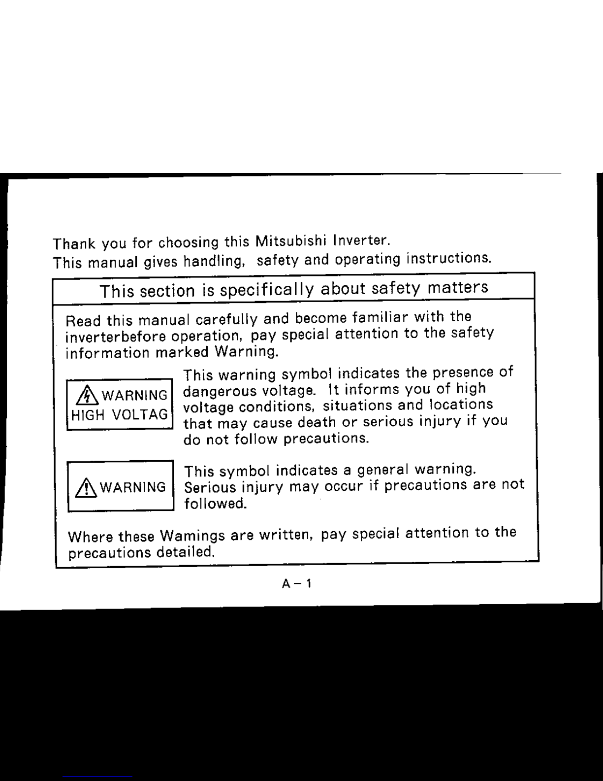
Thank you
for
choosing this Mitsubishi Inverter.
This manual gives handling, safety and operating instructions.
Th is section is
specifica
Ily a bout
safety
matters
Read
this
manual
carefully
and become
familiar
with
the
inverterbefore
operation, pay special
attention
to the
safety
information
marked
Warning.
This
warning
symbol indicates the presence
of
LtWARNING
dangerous voltage.
It
informs
you
of
high
HIGH VOLTAG
voltage conditions,
situations
and
locations
that
may
cause death
or
serious
injury
if you
do
not
follow
precautions.
&WARNING
This
symbol
indicates a general
warning.
Serious
injury
may
occur
if
precautions
are
not
followed.
Where these Wamings
are
written,
pay special
attention
to
the
precautions detailed.
A-l
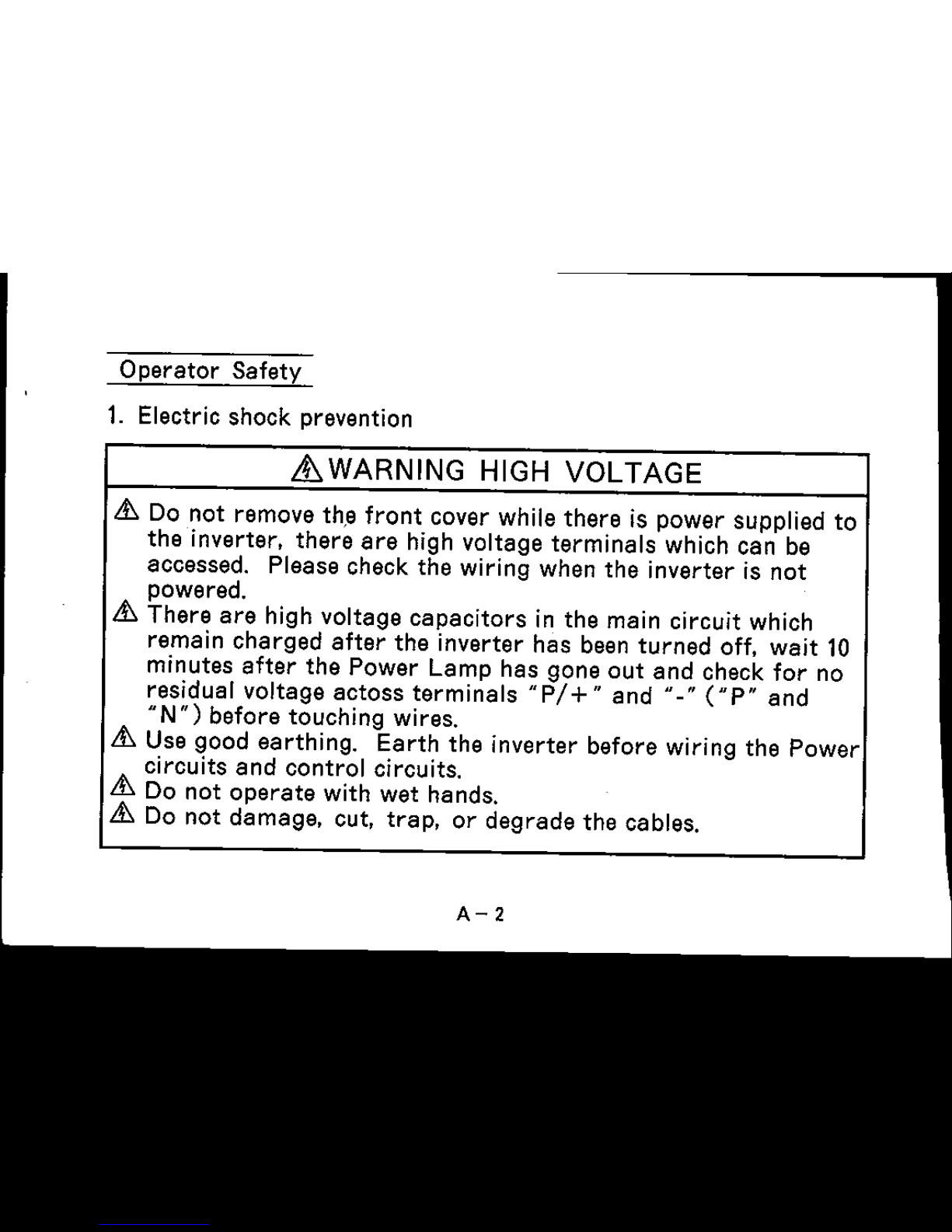
Operator
Safety
1. Electric shock prevention
it
WARNING HIGH
VOLTAGE
&. Do
not
remove th,e
front
cover while
there
is
power
supplied
to
the
inverter,
there
are
high voltage
terminals
which can be
accessed. Please check
the
wiring when
the
inverter
is
not
powered.
&.
There
are
high voltage
capacitors
in
the
main circuit which
remain
charged
after
the
inverter
has
been
turned
off,
wait
10
minutes
after
the
Power
Lamp
has
gone
out
and
check
for
no
residual voltage
actoss
terminals
"P!+"
and
<::
("P"
and
"N")
before
touching wires.
&. Use good
earthing.
Earth
the
inverter
before wiring
the
Power
circuits
and
control
circuits.
&. Do
not
operate
with wet hands.
&. Do
not
damage,
cut,
trap,
or
degrade
the
cables.
A-2

2.
Fire
Prevention
it. WARNING
6 Do
not
mount
on
or
near
combustible
material
(such
as
wood)
6 Use a
circuit
breaker
on
the
supply
side
of
the
inverter
to
prevent
high
current
flow in
the
case
of
a fault.
6 Do
not
connect
a
resistor
directly
to
terminals
"P"
and
"N".
3. I
njury
Prevention
it. WARNING
6
Only
supply
the
inverter
with
the
voltage
on
the
nameplate
and
in
the
Manual
Specification
section.
6
Other
voltages
may
cause
the
inverter
to
fail.
6
Care
should
be
taken
when
wiring
to
ensure
correct
terminals
are
used. Check
polarity
etc
...
6 Do
not
touch
the
inverter
while it is
powered
as
certain
parts
become
hot.
A-3
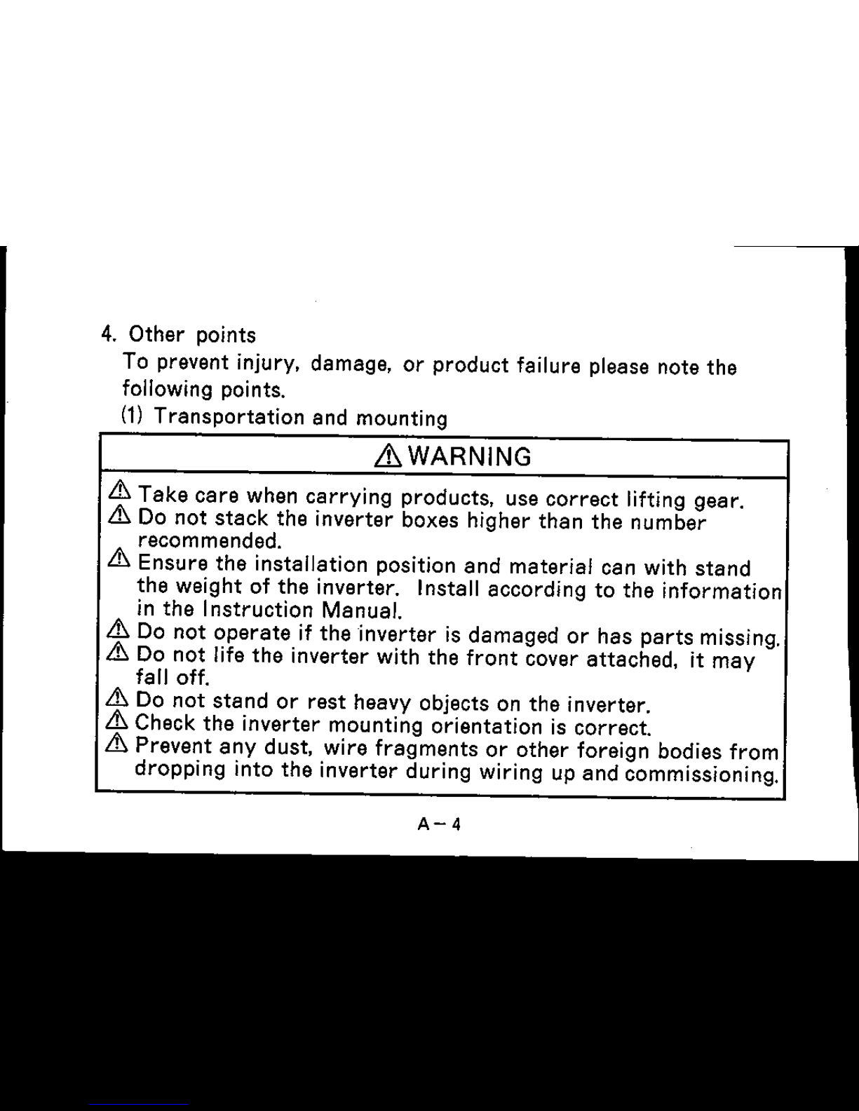
4.
Other
points
To prevent injury. damage.
or
product
failure please note
the
following points.
(1)
Transportation
and mounting
~WARNING
&
Take
care
when
carrying
products.
use
correct
lifting
gear.
& Do
not
stack
the
inverter
boxes higher
than
the
number
recommended.
&
Ensure
the
installation
position
and
material
can
with
stand
the
weight
of
the
inverter. Install
according
to
the
information
in
theInstruction
Manual.
& Do
not
operate
if
the
inverter
is
damaged
or
has
parts
missing.
& Do
not
life
the
inverter
with
the
front
cover
attached.
it
may
falloff.
& Do
not
stand
or
rest
heavy objects on
the
inverter.
& Check
the
inverter
mounting
orientation
is
correct.
&
Prevent
any
dust.
wire
fragments
or
other
foreign
bodies
from
dropping
into
the
inverter
during
wiring up
and
commissioning.
A-4
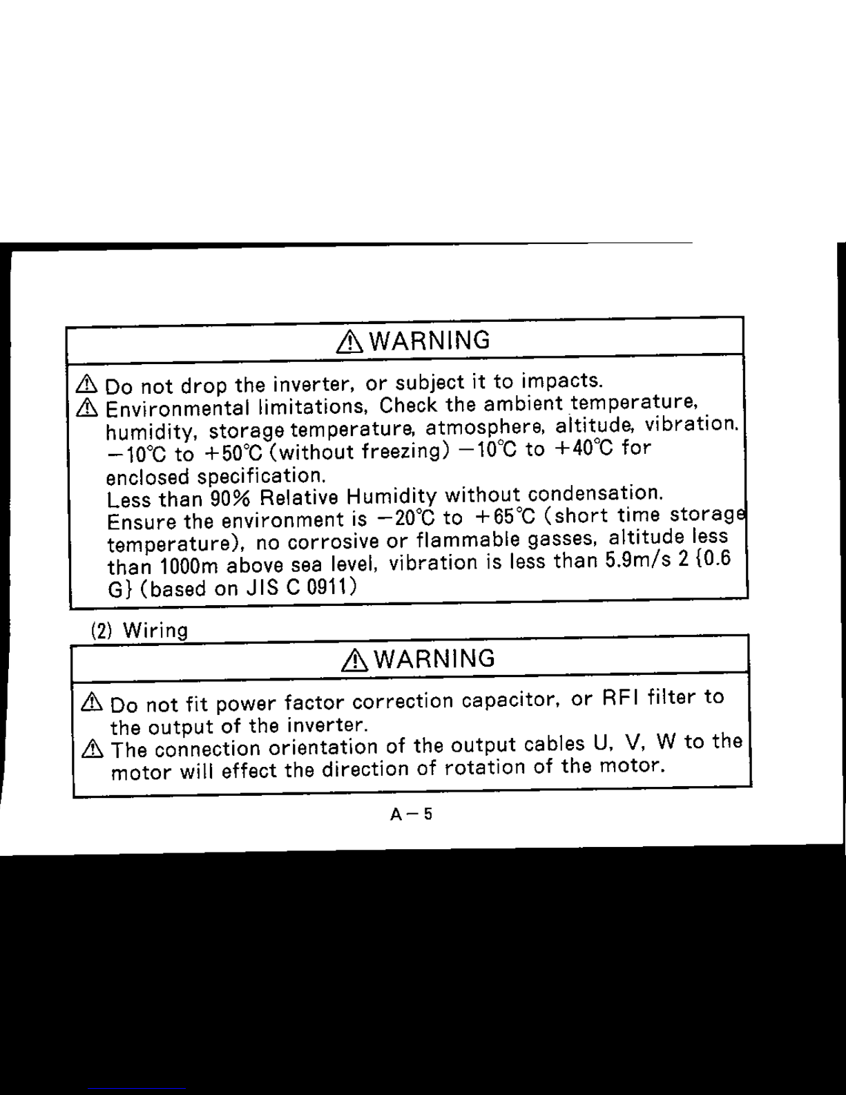
LhWARNING
Lt:.
Do
not
drop
the
inverter.
or
subject
it
to
impacts.
Lt:.
Environmental
limitations. Check
the
ambient
temperature.
humidity.
storage
temperature.
atmosphere,
altitude.
vibration.
-10°C
to +50°C
(without
freezing)
-10"C
to +40°C
for
enclosed specification.
Less
than
90% Relative Humidity
without
condensation.
Ensure
the
environment
is
-20°C
to +65°C
(short
time
storage
temperature).
no
corrosive
or
flammable
gasses,
altitude
less
than
1000m
above
sea
level,
vibration
is less
than
5.9m/s 2 {0.6
G)
(based
on
JIS
C 0911)
------------------'
(2)
Wiring
LhWARNING
Lt:.
Do
not
fit
power
factor
correction
capacitor.
or
RFI filter
to
the
output
of
the
inverter.
Lt:.
The
connection
orientation
of
the
output
cables
U. V. W
to
the
motor
will
effect
the
direction
of
rotation
of
the
motor.
A-5
(3)
Trial run
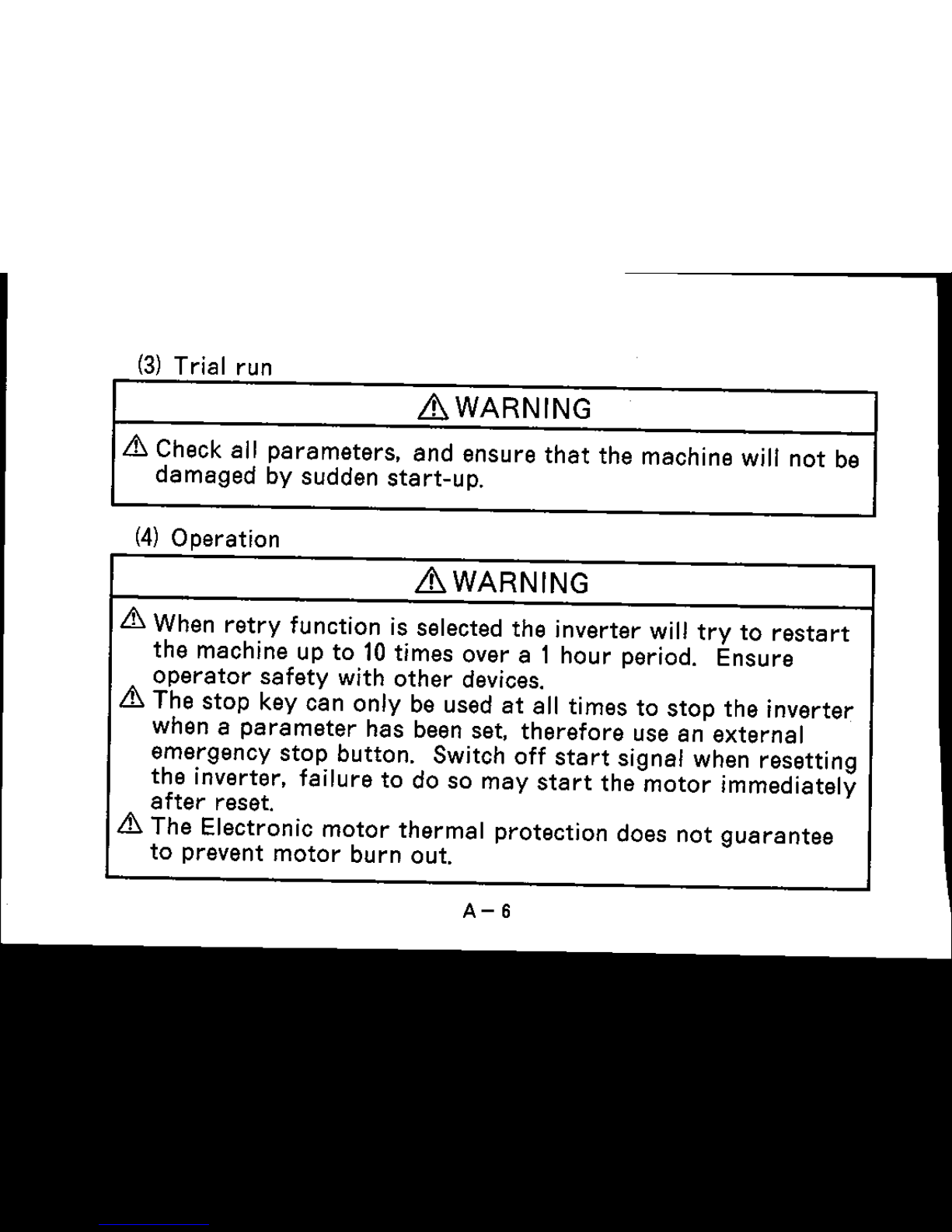
LhWARNING
.&
Check all
parameters.
and
ensure
that
the machine will
not
be
dameged
by sudden
start-up.
(4)
Operation
LhWARNING
.&
When
retry
function is selected the inverter will
try
to
restart
the
machine up to 10 times over a 1 hour period. Ensure
operator
safety
with
other
devices.
.&
The
stop
key can only be used
at
all times to
stop
the
inverter
when a
parameter
has been set.
therefore
use an
external
emergency
stop
button. Switch off
start
signal when resetting
the
inverter. failure to do so
may
start
the
motor
immediately
after
reset.
.&
The Electronic
motor
thermal
protection does not
guarantee
to prevent
motor
burn out.
A-6
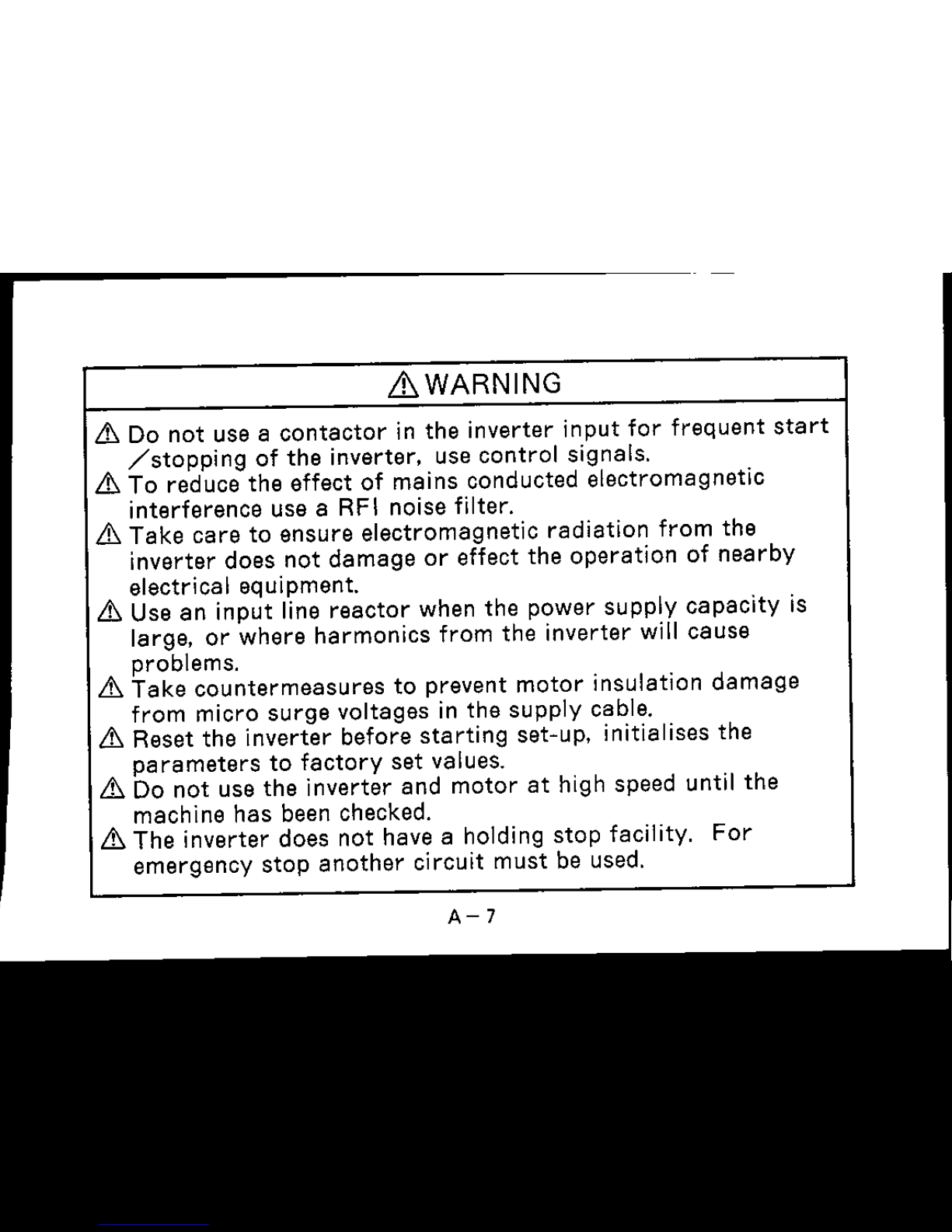
LhWARNING
.6';
Do
not
use a
contactor
in
the
inverter
input
for
frequent
start
/stopping
of
the
inverter. use
control
signals
.
.6';
To reduce
the
effect of
mains
conducted
electromagnetic
interference
use a RFI noise filter .
.6';
Take
care
to
ensure
electromagnetic
radiation
from
the
inverter
does
not
damage
or
effect
the
operation
of
nearby
electrical equipment.
.6';
Use an
input
line
reactor
when
the
power
supply
capacity
is
large.
or
where
harmonics
from
the
inverter
will
cause
problems
.
.6';
Take
countermeasures
to
prevent
motor
insulation
damage
from
micro
surge
voltages
in
the
supply
cable.
.6';
Reset
the
inverter
before
starting
set-up. initialises
the
parameters
to
factory
set
values.
.6';
Do
not
use
the
inverter
and
motor
at
high speed until
the
machine
has
been checked.
.6';
The
inverter
does
not have a holding
stop
facility.
For
emergency
stop
another
circuit
must
be used.
A-7
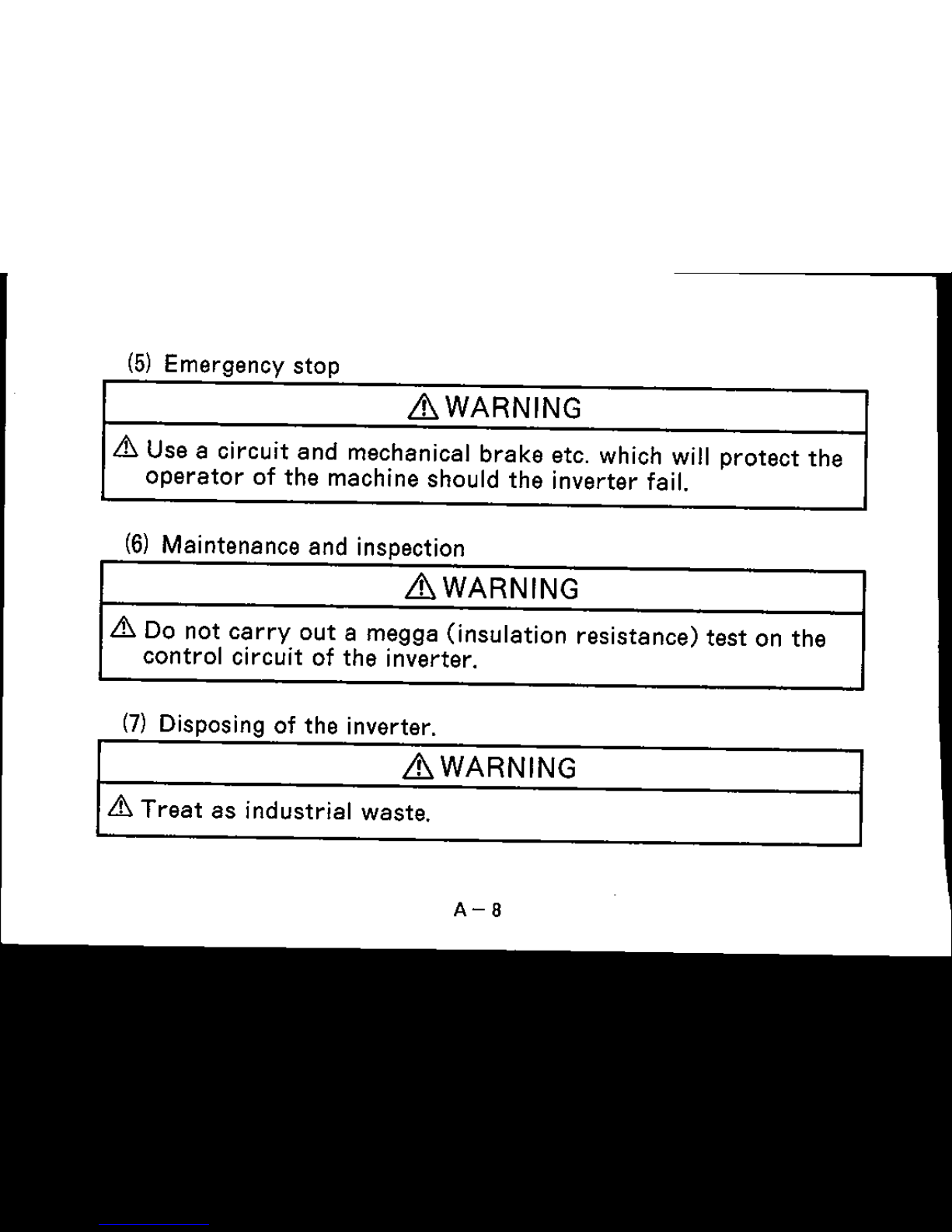
(5) Emergency
stop
~WARNING
.&.
Use a
circuit
and
mechanical
brake
etc. which will
protect
the
operator
of
the
machine should
the
inverter
fail.
(6)
Maintenance
and
inspection
~WARNING
.&.
Do not
carry
out
a
megga
(insulation
resistance)
test
on
the
control
circuit
of
the
inverter.
(7) Disposing of
the
inverter.
~WARNING
.&.
Treat
as
industrial
waste.
A-a
(8)
General
Many
of
the
diagrams
and
drawings
in the
instruction
manual
show the
inverter
without
a cover,
or
partially
open, never
run
the
inverter
like this.
Always
replace the cover and ensure
adequate cooling etc. before using the inverter.
A-9

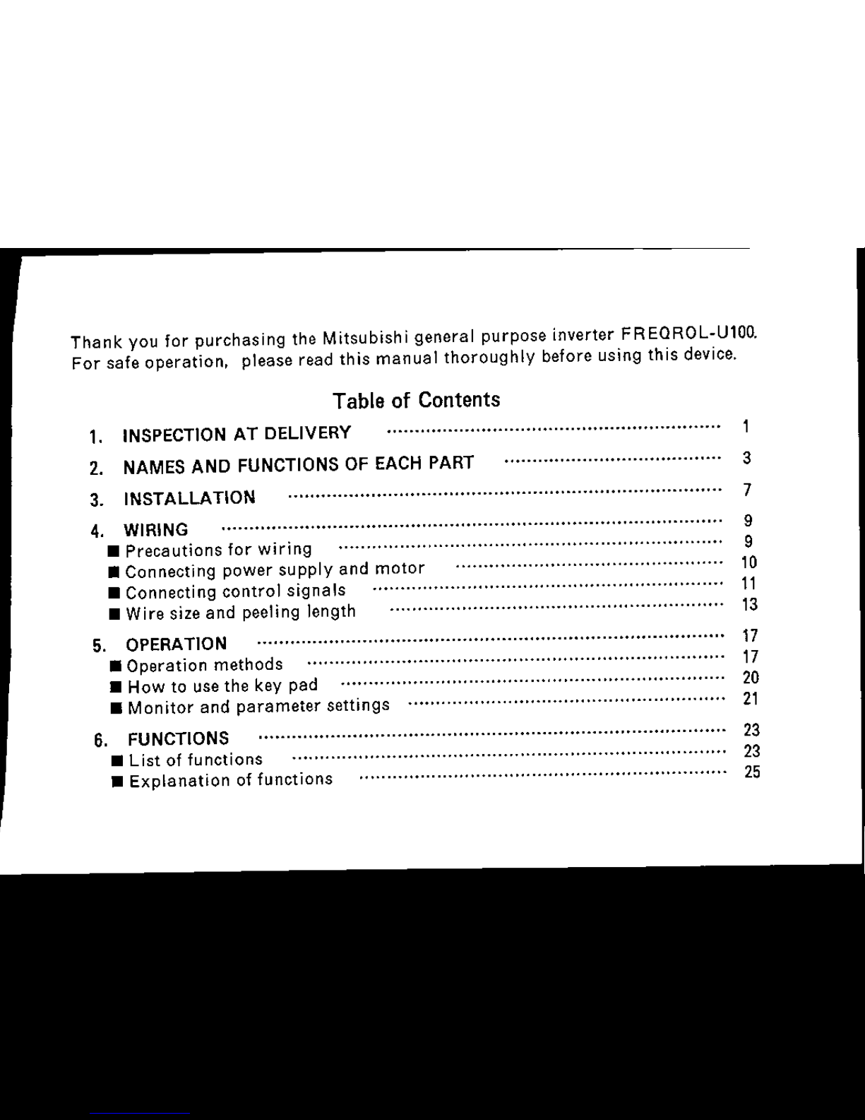
Thank
you
for
purchasing
the
Mitsubishi
general
purpose
inverter
FREQROL-U100.
For
safe
operation,
please
read
this
manual
thoroughly
before
using
this
device.
Table of Contents
1. INSPECTION AT
DELIVERy·
..···..··..·..· ·· · ····..· ··........ ,
2. NAMES AND FUNCTIONS OF EACH PART 3
3. INSTALLATION 7
4. WIRING 9
•
Precautions
for
wiring
,....................................................
9
•
Connecting
power
supply
and
motor
10
•
Connecting
control
signals
11
•
Wire
size
and
peeling
length
13
5. OPERATION 17
•
Operation
methods
,
,.....
17
•
How
to use
the
key
pad
20
•
Monitor
and
parameter
settings
21
6. FUNCTIONS 23
•
List
of
functions
23
•
Explanation
of
functions
25
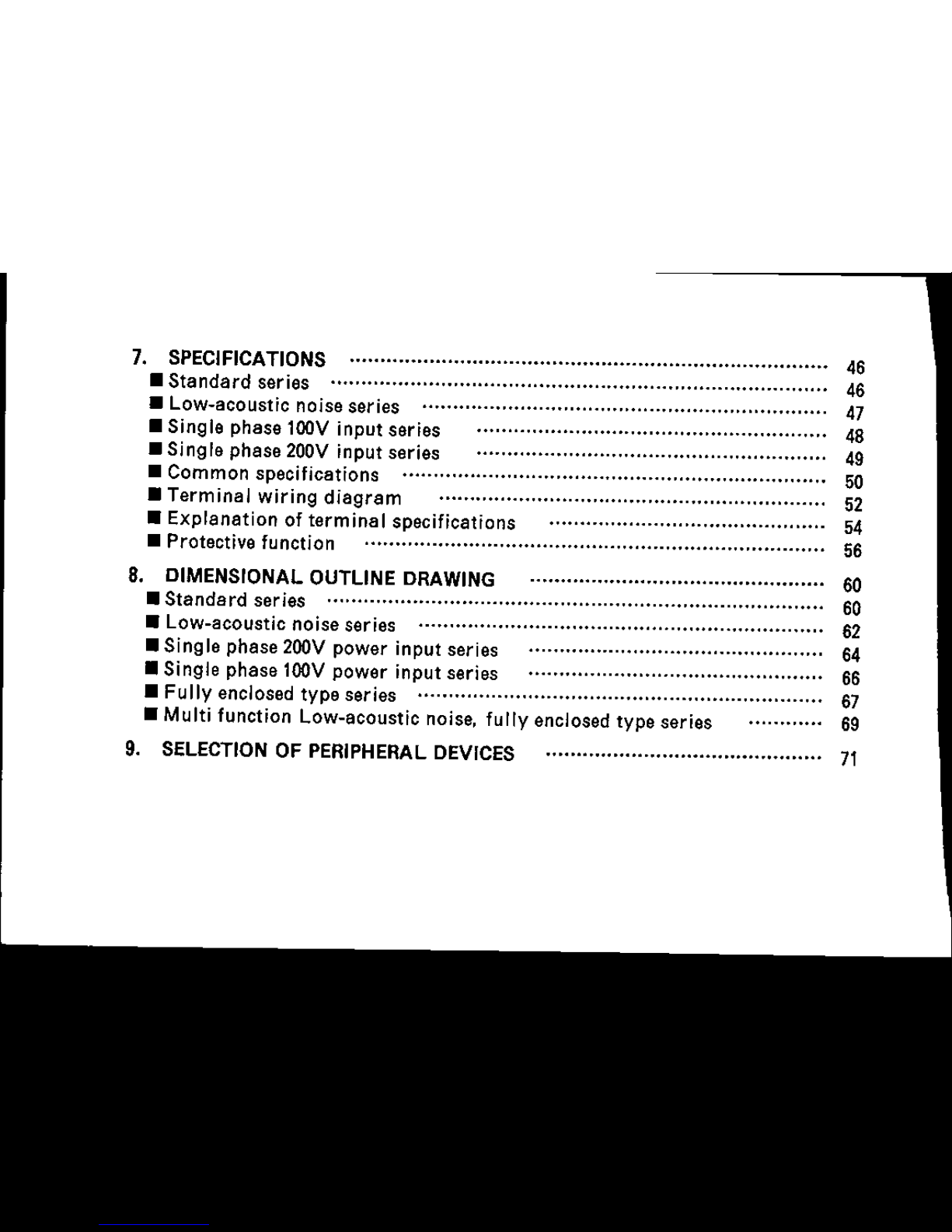
7.
SPECIFICATIONS
46
• Standard series 46
• Low-acoustic noiseseries 47
• Single phase100V input series 48
• Single phase
20DV
input series 49
• Common specifications 50
• Terminal wiring diagram 52
• Explanation of terminal specifications 54
• Protectivefunction 56
8.
OIMENSIONAL
OUTLINE
ORA
WING
60
• Standard series 60
• Low-acoustic noise
series
62
• Single phase200V power input
series
64
• Single phase100V power input series 66
• Fully
enclosed
type series 67
• Multi function Low-acoustic
noise,
fully
enclosed
type series 69
9.
SELECTION
OF
PERIPHERAL
OEVICES
71
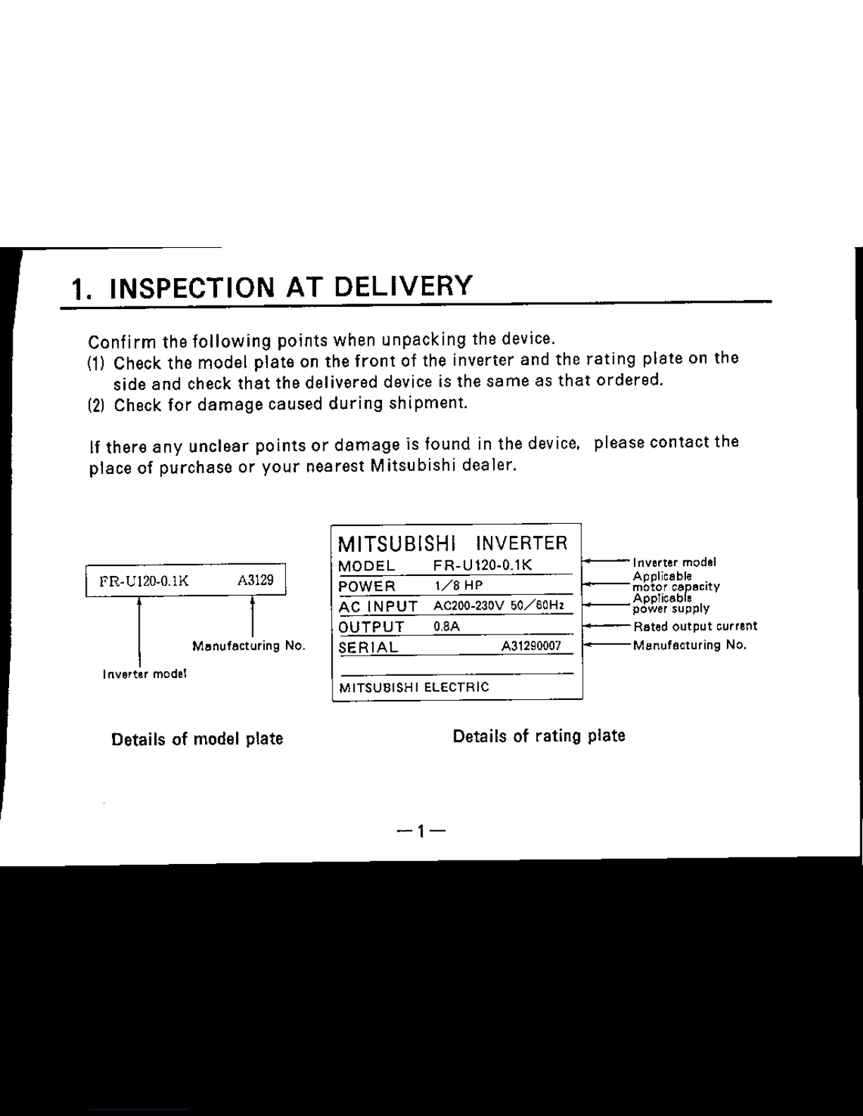
1. INSPECTION AT DELIVERY
Confirm the
following
points when unpacking the device.
(1)
Check
the
model
plate
on
the
front
of the
inverter
and
the
rating
plate
on
the
side
and
check
that
the delivered device is the
same
as
that
ordered.
(2)
Check
for
damage caused
during
shipment.
If
there
any
unclear
points
or
damage
is
found
in
the
device,
please
contact
the
place
of
purchase
or
your
nearest
Mitsubishi
dealer.
FR-U120-0.1K
Menufecturing No.
Inverter model
Details of model plate
MITSUBISHI
INVERTER
MODEL
FR-U120·0.1K
I---
POWER
1/8
HP
I--
ACINPUT
AC200-230V
50/60Hz
I--
OUTPUT
a.8A
~
SERIAL
A31290007
MITSUBISHI
ELECTRIC
Details of rating plate
-1-
Inverter model
Applicable
A~~~i~;~Pe"citY
power supply
Rated
output
current
Manufacturing No.
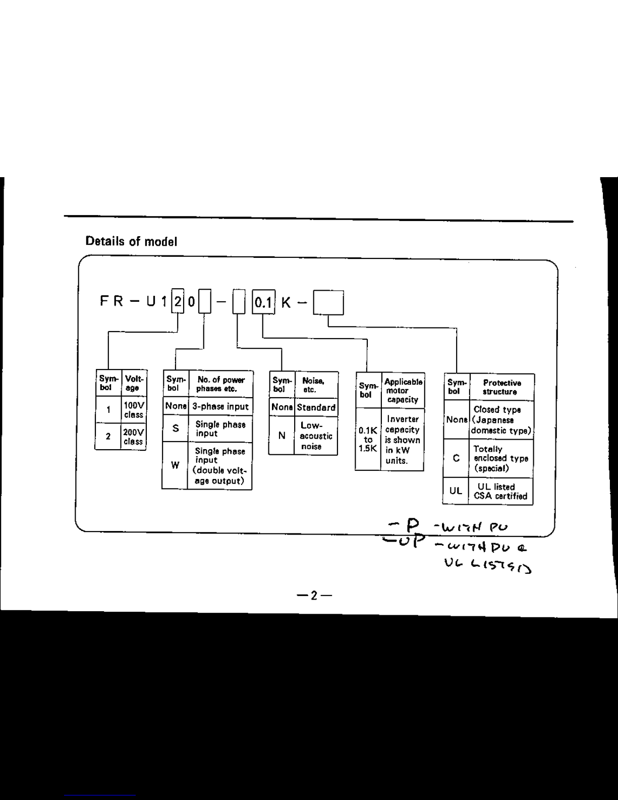
Details of model
K-
Sy~
Volt-
Sy~
No.of pow.-
Sy~
Noise,
Sy~
Applicable
Sy~
Protective
001
'g'
001
plleS&S
etc. 001 etc.
,"
motor 001
structure
capacity
100V None a-phase
input
None
Standard
Closed type
class
Inverter None
(Japanese
S
Single phese Low-
O.1K
capacity
domestic
type)
2
200V
input
N
acoustic
'0
is
shown
class
noise
1.5K
in leW
Totolly
Single phose
units.
C
enclosed
type
W
input
(special)
(double
vert-
eae
output)
Ul
UL listed
CSA certified
-
p
-tv
l~t-I
pv
~l..1
-WI,,,,
pv
...
V<-
'-
{Sol
'7
(~
-2-
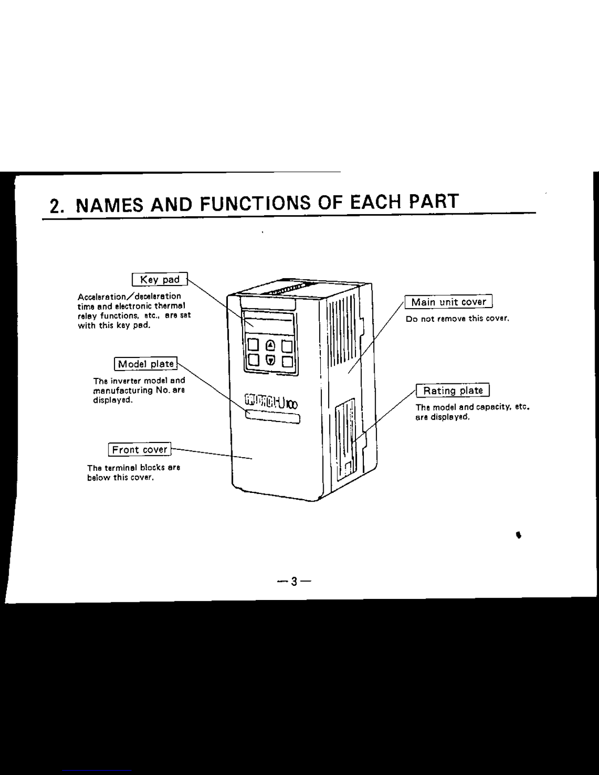
2. NAMES AND FUNCTIONS OF EACH PART
Key pad
Acceleration/deceleration
time and electronic thermal
relay functions. etc.. are set
with this key pad.
Model plate
The inverter model lind
manufacturing No. are
displayed.
Front
cover
The terminal blocks are
below this cover.
-3-
'n
I Main
unit
cover I
Do not remove this cover.
I
Rating
plate I
The model and cepecitv, etc.
lire dlspleved.
•
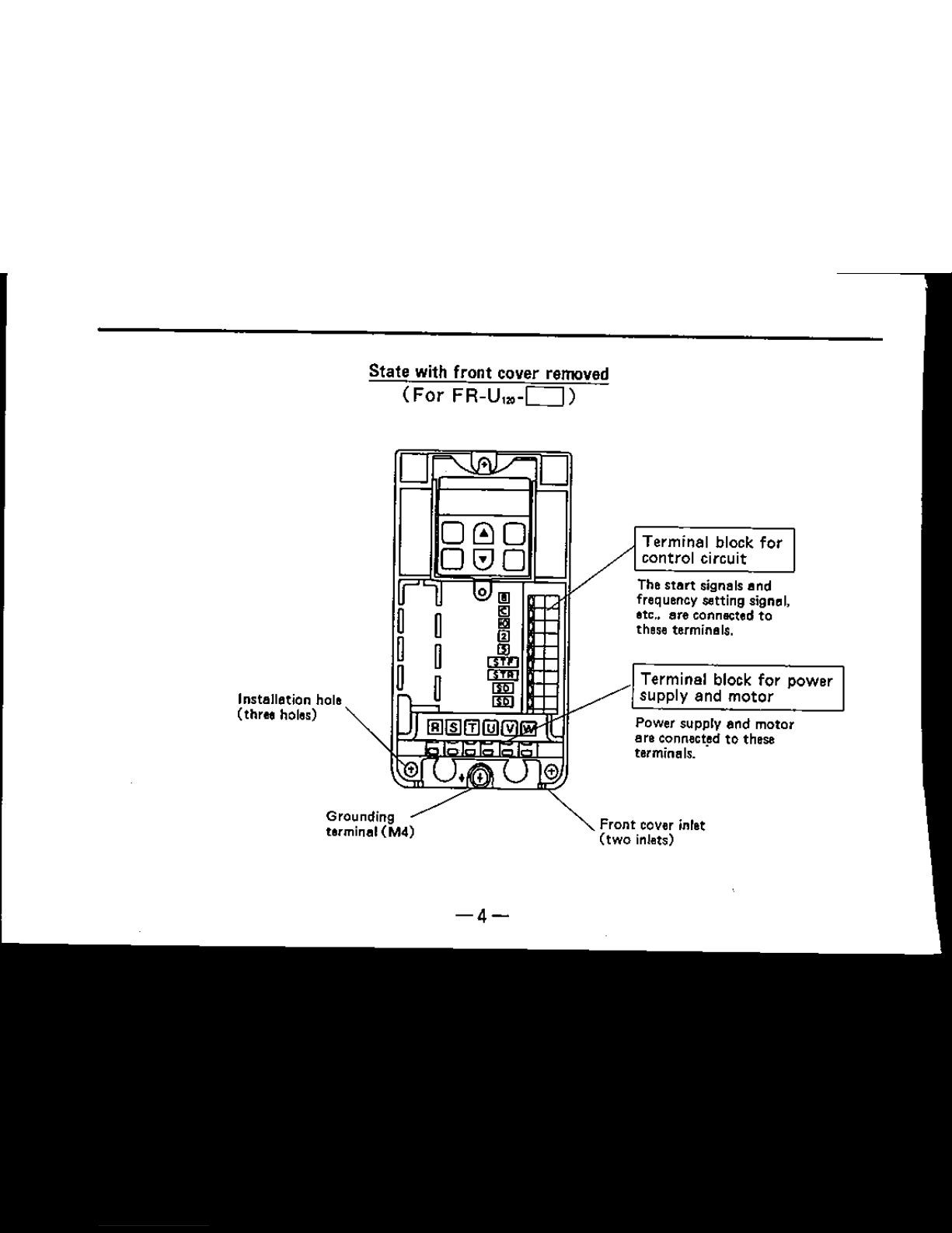
Front
cover inlet
(two
inlets)
Grounding
terminlll(M4)
Terminal block
for
power
supply and
motor
Terminal block
for
control circuit
The
start
signals lind
frequency settlng signal,
etc.. lire connected to
these terminals.
Power supply lind motor
lire connected to these
terminals
..
000
O(VO
State with front cover removed
(For
FR-U,.-D)
Instlllllltion hole
(three holes)
-4-
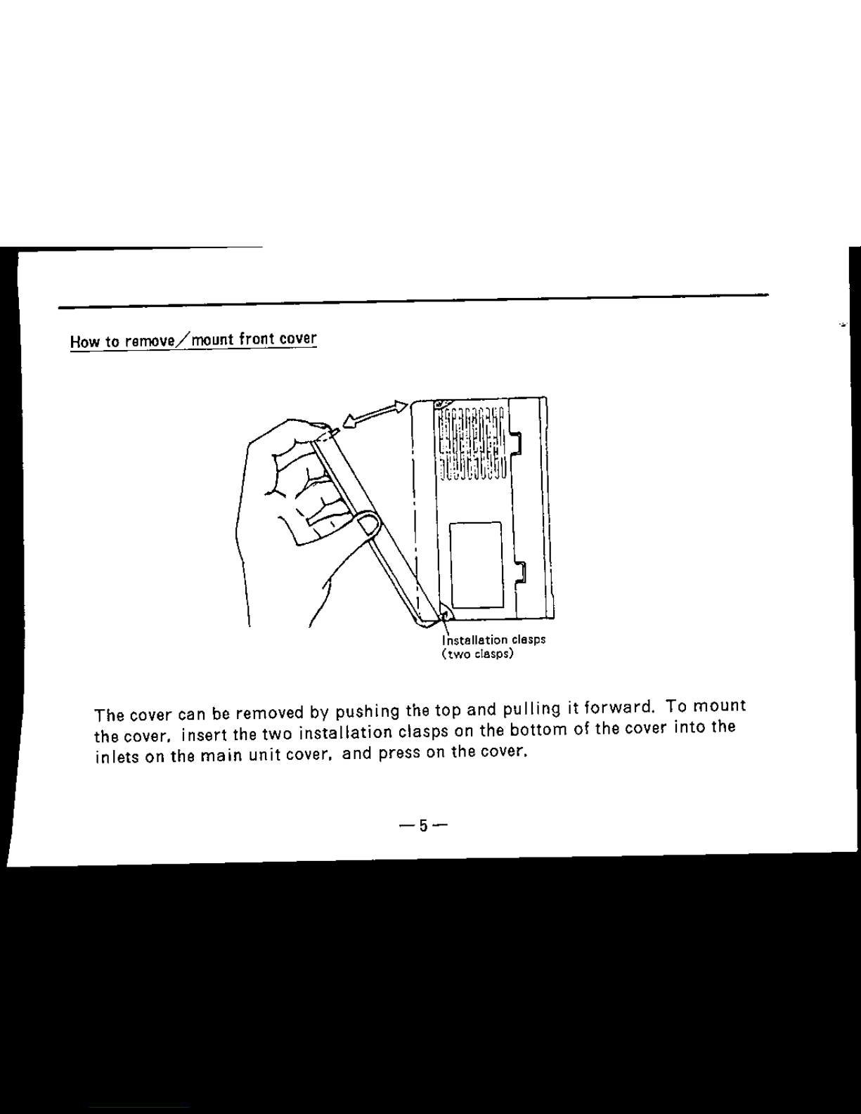
How
to
remove/
mountfront cover
Installation clasps
(two
clasps)
The
cover can be removed by
pushing
the
top
and
pulling
it
forward.
To
mount
the
cover.
insert
the
two
installation
clasps
on
the
bottom
of
the
cover
into
the
inlets
on
the
main
unit
cover.
and
press
on
the
cover.
-5-
Exclusive wiring cover
Excrusive wiring cover
(protective bushing)
~llEJlSlrn(jjJmoo
II
OCl
ClOCl
!:I
""
\
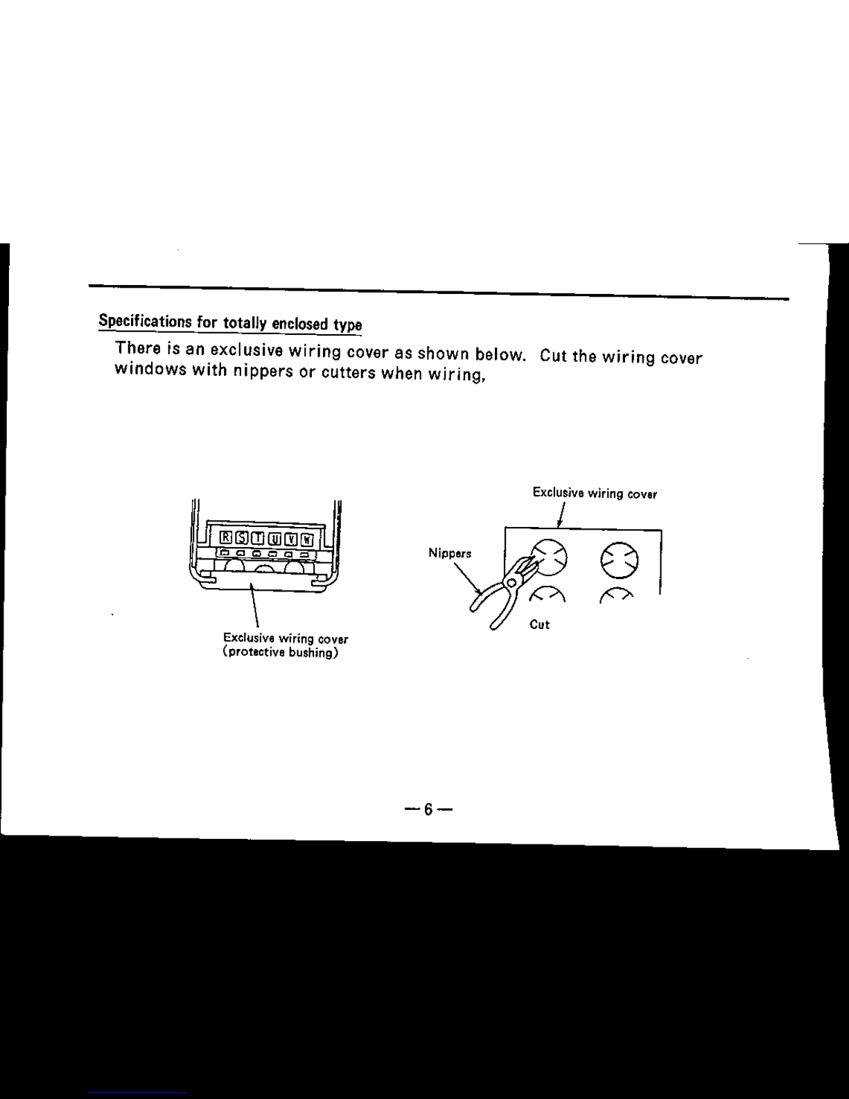
Specifications for totally
enclosed
type
There
is an exclusive
wiring
cover
as
shown
below. Cut the
wiring
cover
windows
with
nippers
or
cutters
when
wiring,
-6-
Wrong
Sideways
installation
Wrong
Horizontal
installation
~
FR[QROL
.
~~
If
.,
Right
Vertical
installation
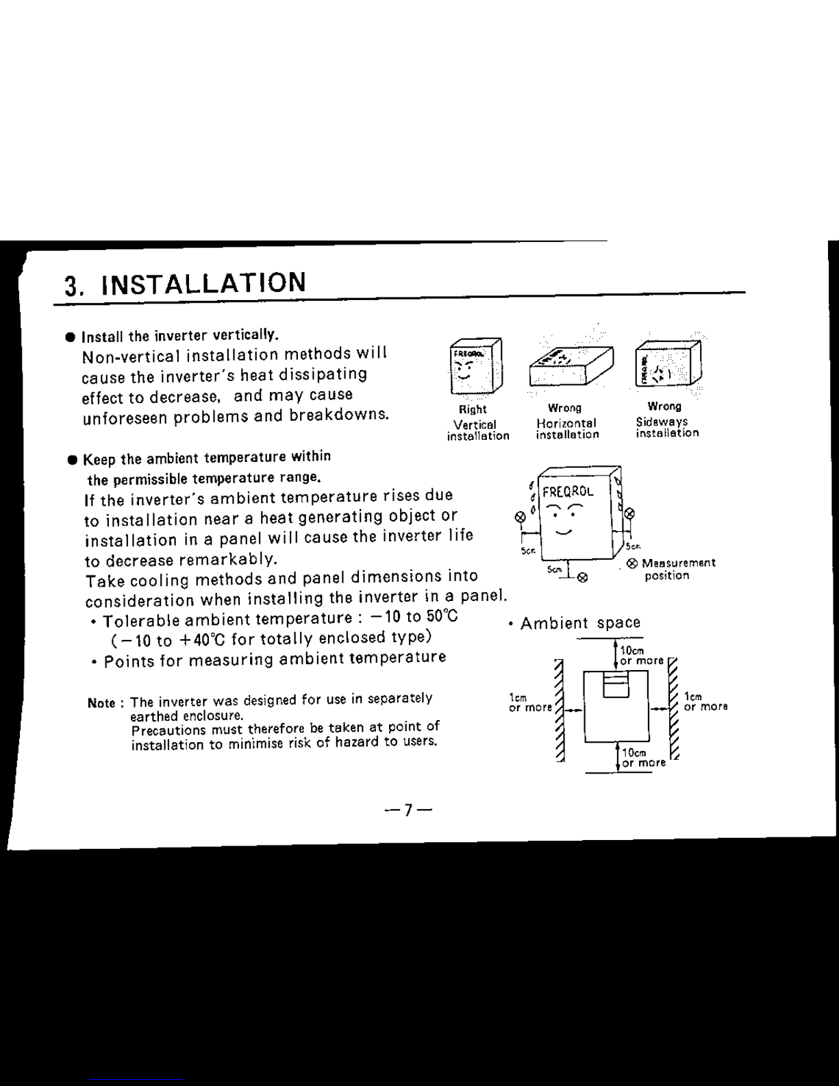
Note:
The inverter was designed for use in separately
earthed enclosure.
Precautions must therefore be
taken
at
point of
installation to minimise risk.
of
hazard to users.
• Keep
the
ambient
temperature
within
the permissible
temperature
range.
If
the
inverter's
ambient
temperature
rises
due
to
installation
near
a
heat
generating
object
or
installation
in a panel
will
cause the inverter
life
to
decrease
remarkably.
Take
cooling
methods
and
panel
dimensions
into
consideration
when
installing
the
inverter
in a
panel.
•
Tolerable
ambient
temperature:
-10
to
50°C
(-10
to
+40°C
for
totally
enclosed
type)
•
Points
for
measuring
ambient
temperature
• Install the inverter vertically.
Non-vertical
installation
methods
will
cause
the
inverter's
heat
dissipating
effect
to
decrease,
and
may
cause
unforeseen problems and breakdowns.
3.
INSTALLATION
-]-
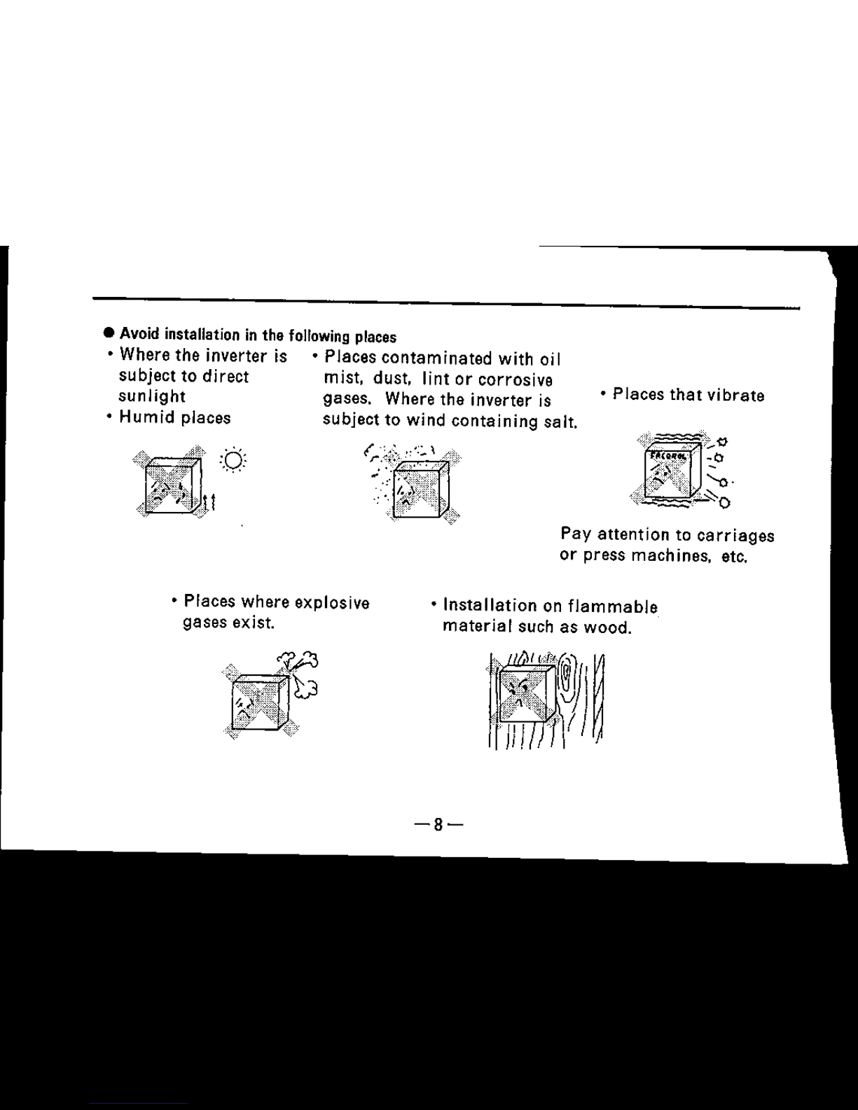
•
Places
that
vibrate
Pay
attention
to
carriages
or
press
machines, etc.
•
Installation
on
flammable
material
such
as
wood.
• Places where explosive
gases
exist.
• Avoid installation in the following places
• Where the inverter is •
Places
contaminated
with oil
subject to
direct
mist, dust, lint or corrosive
sunlight
gases. Where the inverter is
• Humid places subject to wind
containing
salt.
-8-
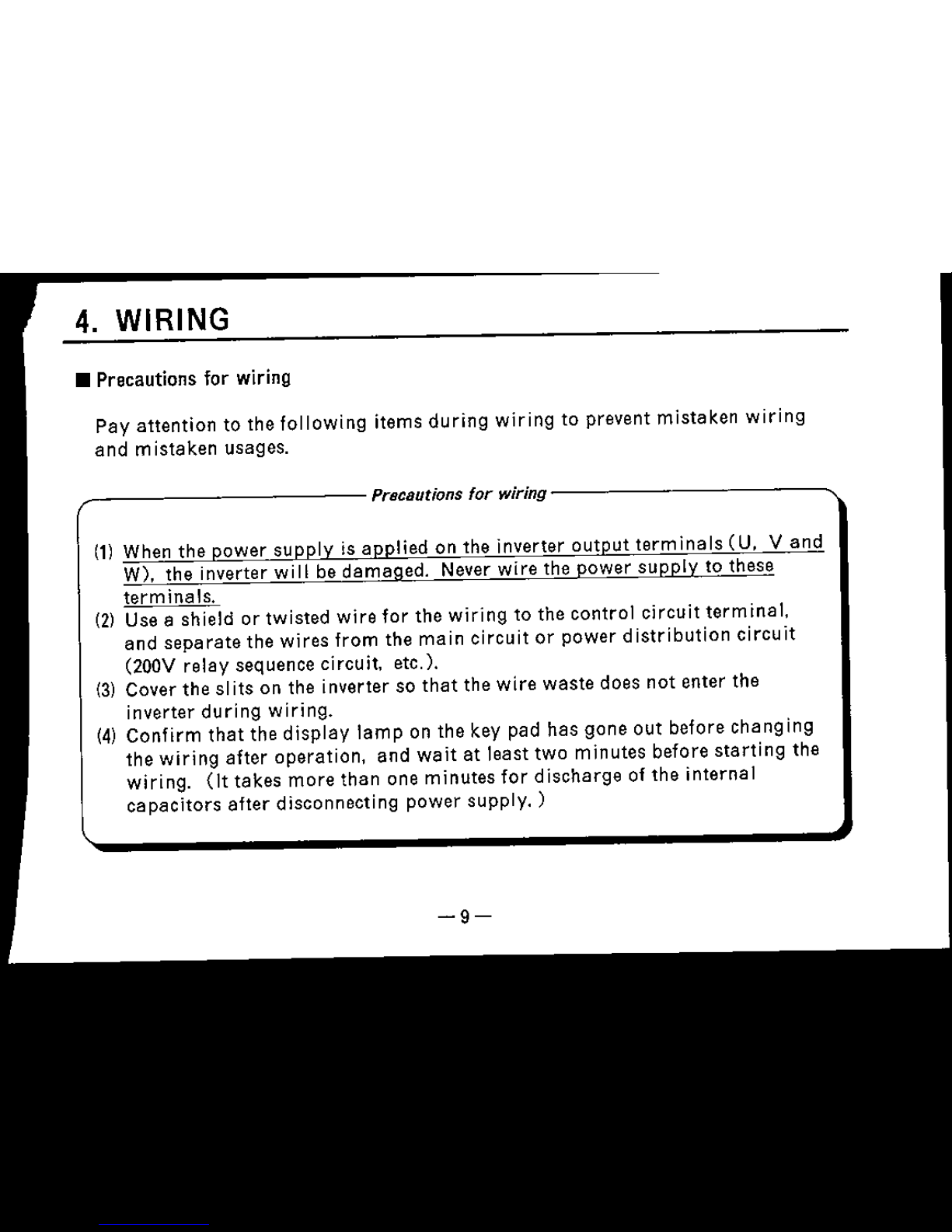
4.
WIRING
• Precautions for wiring
Pay attention to the
following
items
during
wiring
to prevent mistaken
wiring
and mistaken usages.
,------------
Precautions
for
wirlng-------------..
(1)
When the power supply is applied on the inverter
output
terminals
CU,
Vand
W), the inverter will be damaged. Never wire the power
supply
to these
terminals.
(2)
Use a shield or twisted wire for the wiring to the control circuit
terminal,
and separate the
wires
from
the
main
circuit
or power
distribution
circuit
(200V
relay
sequence
circuit, etc.).
(3)
Cover
the
slits
on the inverter so
that
the
wire
waste
does
not
enter
the
inverter
during
wiring.
(4)
Confirm
that
the
display
lamp
on the key pad has gone out before changing
the
wiring
after
operation,
and
wait
at
least
two
minutes
before
starting
the
wiring.
(It
takes
more
than
one
minutes
for
discharge
of
the
internal
capacitors
after
disconnecting
power
supply.
)
-9-
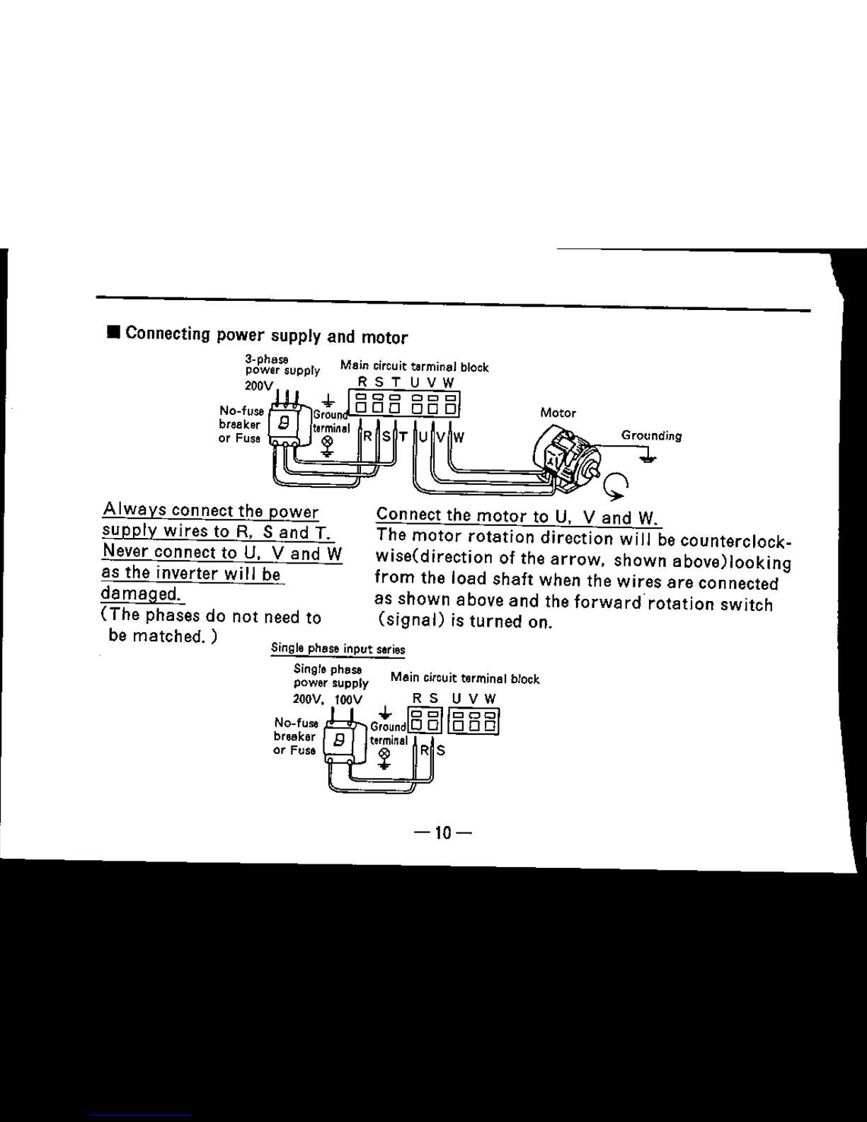
Motor
~~~~~':t,g
Connect the
motor
to U. V
and
W.
The
motor
rotation
direction will be counterclock-
wlsefdlrectlon of the
arrow.
shown
above)looking
from
the load
shaft
when the
wires
are
connected
as
shown
above
and
the forward"
rotation
switch
(signal)
is
turned
on.
No-fuse
breaker
or Fuse
Single phase input series
Single phase Main circuit terminal block
power supply
200V.
tOOV
R 5 U V W
G:undMlooo!
£)
t~rminel
Z
No-fuse
breaker
or Fuse
• Connecting power supply and motor
a-phese
power supply
200V
AI
ways
con nect the power
supply
wires
to R.
Sand
T.
Never connect to U. V and W
as the inverter will be
damaged.
(The
phases
do not need to
be
metched)
-10-
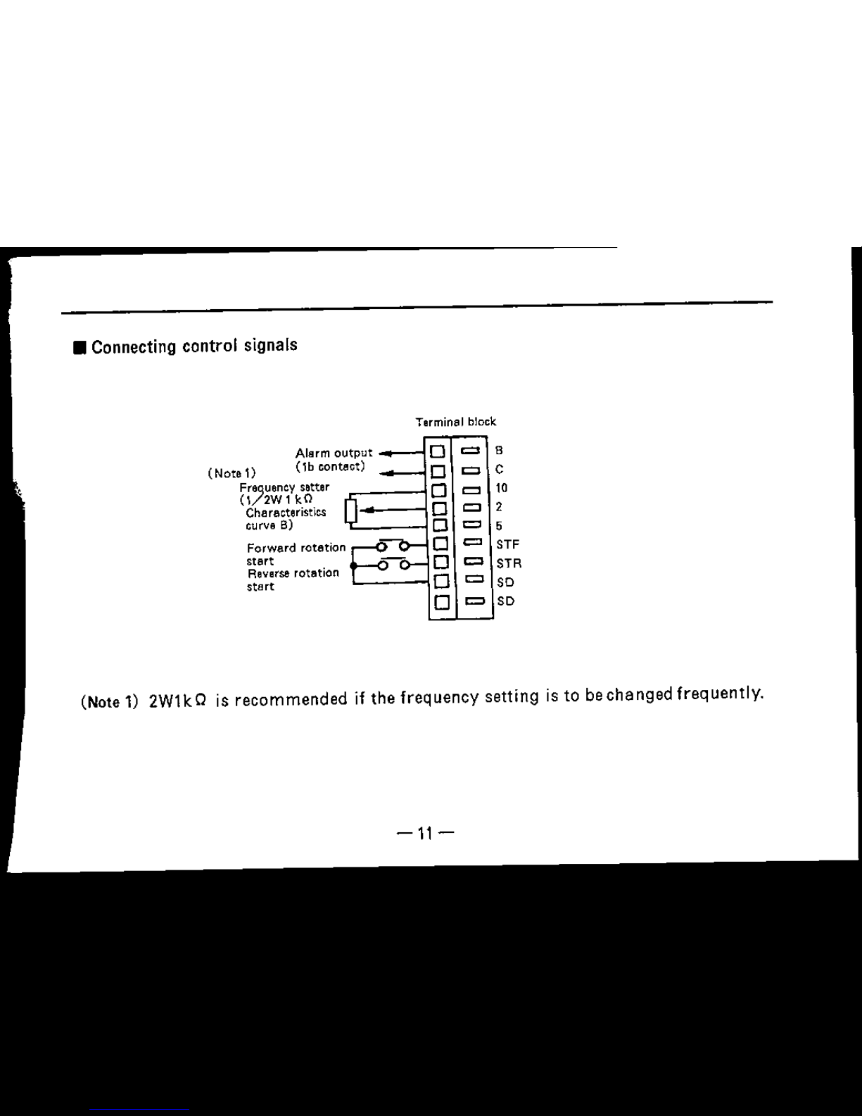
•
Connecting
control
signals
Terminal block
Alarm
output
0
=
8
(Note 1)
(lb
contact)
0
=
C
Fr,uenc
y
setter
0
=
10
(\
2WlkO
0
=
2
Characteristics
curve B)
0
=
5
Forward rotation
0
=
ST'
start
0
=
ST"
Reverse rotation
0
=
start
SD
0
=
SD
(Note 1) 2Wl k Q is
recommended
if
the
frequency
setting
is to be
changed
frequently.
-11-
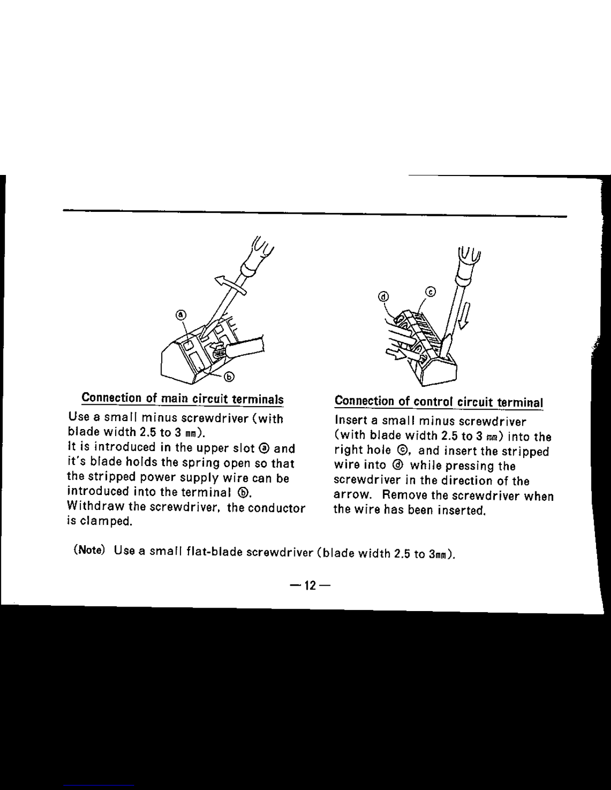
Connection of main circuit terminals
Use a
small
minus
screwdriver
(with
blade
width
2.5 to 3
mm).
It is
introduced
in the
upper
slot@
and
it's
blade
holds
the
spring
open so
that
the
stripped
power
supply
wire
can be
introduced
into
the
terminal
@.
Withdraw
the
screwdriver,
the
conductor
is
clamped.
Connection of control circuit terminal
Insert a
small
minus
screwdriver
(with
blade
width
2.5 to 3
mm)
into the
right
hole
<9,
and
insert
the
stripped
wire
into @
while
pressing
the
screwdriver
in the
direction
of the
arrow.
Remove the
screwdriver
when
the
wire
has
been inserted.
(Note) Use a
small
flat-blade
screwdriver
(blade
width
2.5 to
3mm).
-12-
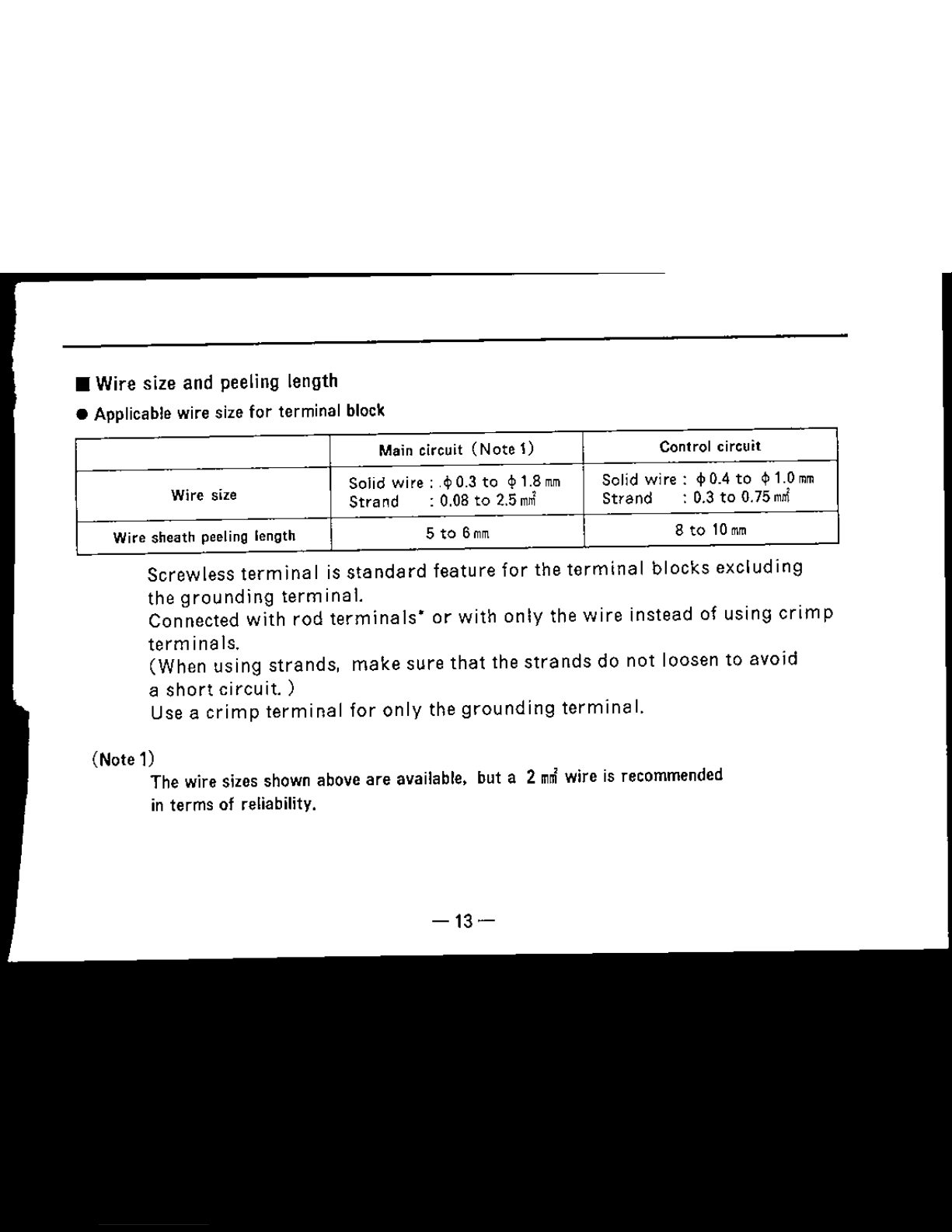
eeling length
lze
for
terminal block
Maincircuit (Note
1) Controlcircuit
ze
Solid
wire:
,$0.3 to
~1.8mm
Solid
wire:
<fl
0.4to ¢l1.0
mm
Strand
:
0.08
to 2.5
mnl
Strand
: 0.3 to
0.75mnl
ling
length
5 to
6mm
8tol0mm
S
terminal
is
standard
feature
for
the
terminal
blocks
excluding
ndinq
terminal.
d
with
rod
terminals"
or
with
only
the
wire
instead
of
using
crimp
s.
ing
strands,
make
sure
that
the
strands
do
not
loosen
to
avoid
ircuit.
)
mp
terminal
for
only
the
grounding
terminal.
lzes shown aboveare available. but a 2
m~
wire is
recommended
f reliability,
-13-
Screwles
the
grou
Ccnnecte
term
ina I
(When
us
a
short
c
Use
a
cri
Wire si
Wire
sheath
pee
(Note 1)
The wire s
in terms 0
•
Wire
size and p
• Applicable wire
s

"Example
of rod
terminals
Applicable
Applicable wire size
Circuit Manufacturer
terminal name
Solid wira
(11m)
Strand wire
(mnl)
TC-1.25
(S)
cjlO.57
to cjl1.44 0.25to1.65
Main
Nichifu Terminal
circuit
TC-2
(S)
cjl1.14to e
t.aa
1.04 to 2.36
terminal
TUB-1.25
cjlO.57tocjl1.44
0.55to1.65
Japan
SolderJess Terminal
Control
TC-0.5
cjl
0.57
to
cjl
0.7
0.25
to
0.75 Nichifu Terminal
circuit
terminal
HO.25/10
.0.57
0.25
Japan
Weidmuller
-14-
Mel
~
nterloC
k
, ,
Power R U
'1M
su
P
P:;y1}
~
~
~~-~
Current
~
loop
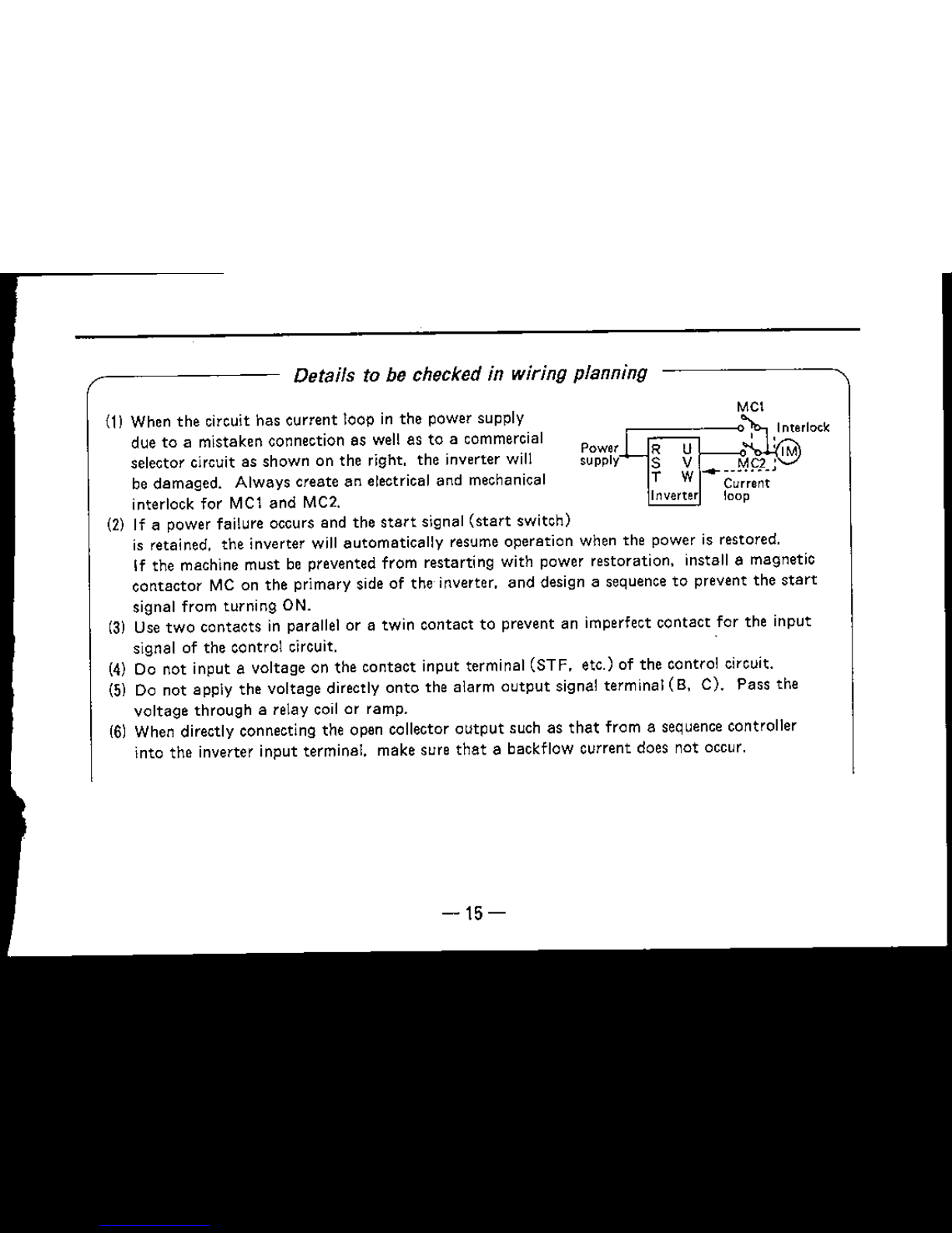
Details to be checked in wiring planning
(1) When
the
circuit has current loop in the power supply
due to a mistaken connection as well as to a commercial
selector circuit as shown on the right, the inverter will
be damaged. Always create an electrical and mechanical
interlock
for
MCl and MC2.
(2) If a power failure occurs and the
start signal
(start
switch)
is retained. the inverter will automatically resume operation when the power is restored.
If the machine must be prevented from restarting with power restoration, install a magnetic
ccntector
MC on the primary side of the inverter, and design a sequence to prevent the
start
signal from turning ON.
(3) Use
two
contacts
in parallel or a twin contact to prevent an imperfect
contact
for the input
signal of the control circuit.
(4) Do not input a voltage on the
contact
input terminal (STF, etc.) of the control circuit.
(5) Do not apply the voltage directly
onto
the alarm
output
signal terminal
(8,
C). Pass the
voltage
through
a relay coil or ramp.
(6) When directly connecting the open collector
output
such as
that
from a sequence controller
into the inverter input terminal. make sure
that
a backflow current does not occur.
-15-
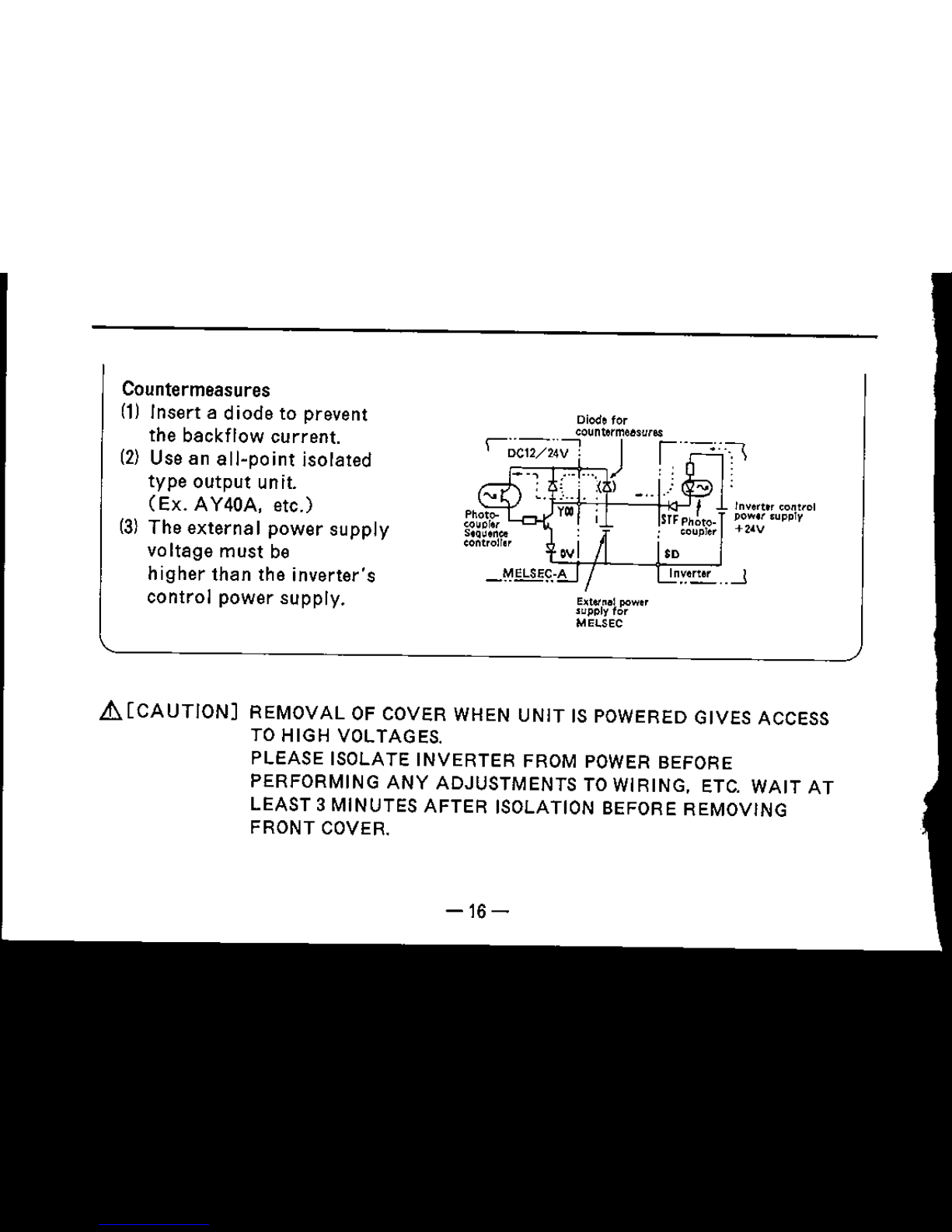
Countermeasures
(1)
Insert a diode to prevent
the backflow current.
(2) Use an
all-point
isolated
type output unit.
(Ex.
AY40A,
etc.)
(3) The external power supply
voltage must be
higher than the inverter's
control power supply.
Diode for
ecuntermeeswee
r~W2~;-1
...
, j
r'--~:T\
,{ 1
Invert" control
pow"
supply
+2~V
.-.1
E~W"al
power
.upply for
MELSEC
L!I.[CAUTION]
REMOVAL
OF COVER WHEN
UNIT
IS POWERED GIVES ACCESS
TO HIGH VOLTAGES.
PLEASE ISOLATE
INVERTER
FROM POWER BEFORE
PERFORMING
ANY
ADJUSTMENTS TO WIRING, ETC.
WAIT
AT
LEAST 3 MINUTES
AFTER
ISOLATION BEFORE REMOVING
FRONT COVER.
-16-
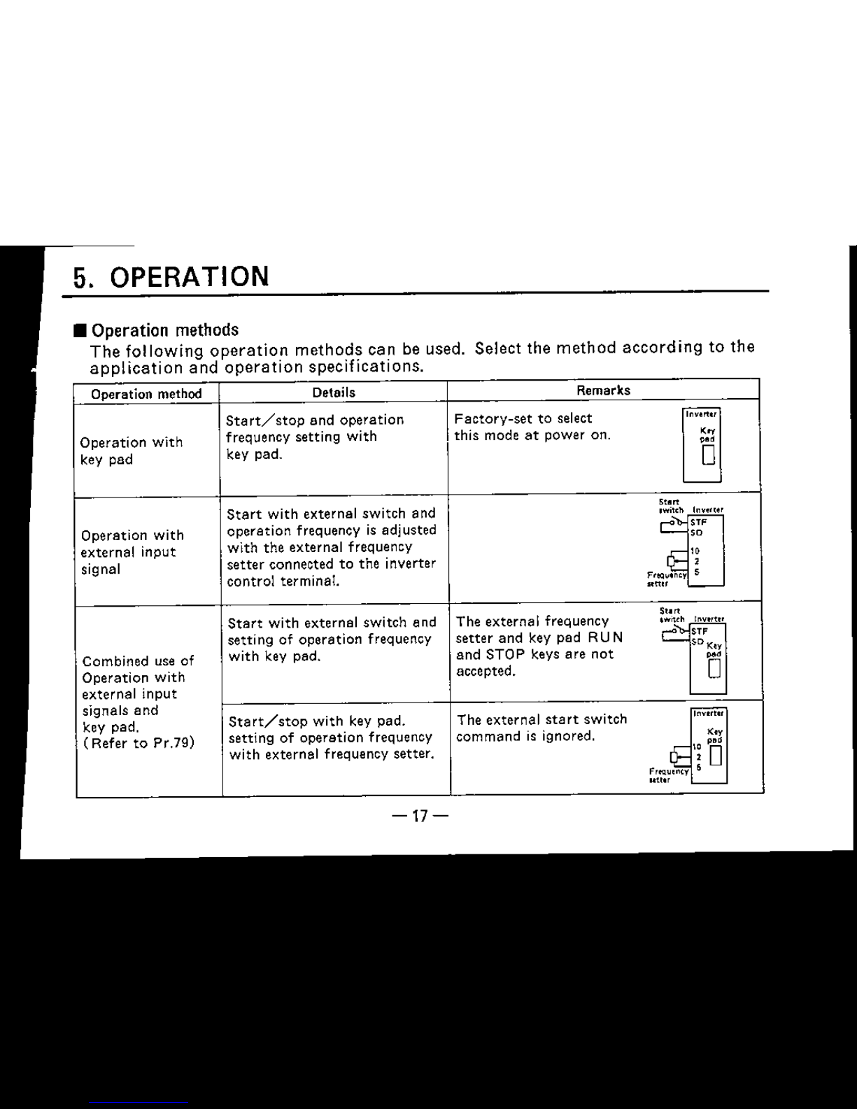
5. OPERATION
•
Operation
methods
The
following
operation
methods
can be used. Select the
method
according
to the
application
and
operation
specifications
Operation method
Details Remarks
Start/stop
and operation
Factory-settoselect
rn
Operation
with
frequency
setting
with
this
mode
at
power
on.
'"
key pad
key pad.
Qa
Start
with
external
switch
and
Sto
..
In''''''
,w;lCh
Operation
with
operation
frequency is adjusted
C':
'"
'0
external
input
with
the
external
frequency
.~"
signal
setter
connectedtothe
inverter
F'!Q""cy
~
control
terminal.
Sf""
l-.-
Start
with
external
switch
and The
external
frequency
St."
'WMh
10""'''
settingofoperation
frequency setter and key pad RU N
C':
err
SDK,.
Combined use of
with
key pad.
and
STOP
keys
are
not
~.
Operation
with
accepted.
0
external
input
signals
and
Start/stop
with
key
pad.
The
external
start
switch
lov"'"
key
pad.
(Refer
to
Pr.79)
setting
of
operation
frequency
command
is ignored.
"
''""~
~.
with
external
frequency
setter.
\~
D
s
uUor
'-----
-17-

(Operation
with key
pad)
The key pad
operation
(parameter
No. 79 "1" ) is selected
as
the factory setting.
8 Frequency setting mode is entered.
o
~
Set
frequencyischanged.
8 Setfrequency is fixed.
8 Motor
starts
(forward
rotation)
(Note),
rsroP1
Motor stops.
~
(Note)
To
drive
the
motor
in
the
reverse
direction
with
thelRUNlkey,
short-circuit
between STR
and
SO on the
terminal
block, or set
parameter
No.la to "2".
-18-

( Operation with external input
signal)
Frequency
setter
Motor
NFB
·Inverter
Power
-::~~~====~
R U
supply S V
T W
Forward
rotation_"----J
8TF
Reverse rotation STR
'-----180
10
,
5
• Set
external
operation
mode
(parameter
No.79 "2" ).
(Refer
to the
following
explanation
for the
setting
method.
)
The
start
signals
and
frequency
are
input
with
external
switches
and
frequency
setting
potentio-
meter. The
motor
wi II
operate
when a
signal
is
input
into
STF
(forward
rotation)
or
STR
(reverse
rotation)
and
the
frequency
setterisoperated.
-19-

£[CAUTIONJ
DO NOT USE
ANY
SHARP
OBJECTS ON THE
KEY
PAD,
OR IT
MAY
DAMAGE
THE
MEMBRANE.
Operation command keys
Theseare the RU N and STOP
command keys
for
operating
with
the key pad.
The stop key also functions as the
resetkey when an
alarm
occurs in
the inverter.
I UP key I
IDOWN key
Thesekeys continuously increment
or decrementthe operation
frequency setting or setting value
of variousfunctions.
The value
will
change
only
when
the key is
pressed.
t:
o
8
This key is usedto select
the frequency monitor,
frequency setting and
parameter setting mode.
This key is usedto confirm
and changethe frequency
and setting value
of
various functions.
Display
The frequency,
motor
current
setting value of
various functions. and
alarm
codeare shown
on a 7-segment,
3.digit
display.
MODE key
SET key
•
How
to usethe key
pad
-20-
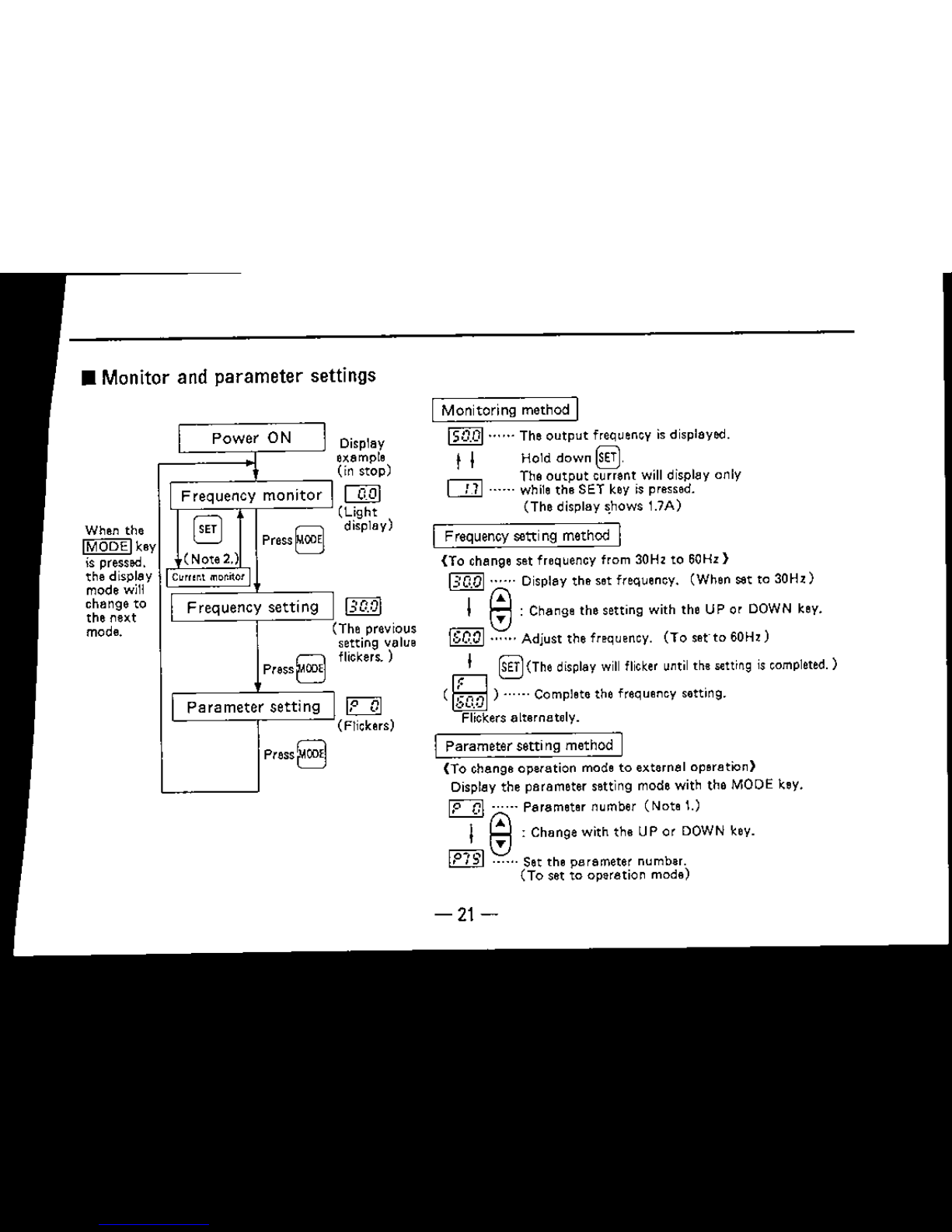
• Monitor and parameter settings
[IQQI.
.The
output
frequency isdisplayed.
t I Hold down
~
The
output
current willdisplay only
[J]
......
whilethe SET key is pressed.
(The display
shows 1.7A)
Monitoring mathOd I
I
Parameter
setti ng method I
(To change operation mode to external operation)
Display the parameter setting mode with the MODE key.
~
...... Parameter number (Note t.)
I
@:
Change with the UP or DOWN key.
rn
......
Set the parameter number.
(To set to operation mode)
[lQ]]
The previous
setting value
flickers.)
~
(Flickers)
Display
example
(in stop)
ITQJ
(light
display)
I
Power
ON
I
Frequency
monitor
I
y
8,,1
Press8
(Note 2.)
y
C",,,r.t
mor.ilor
II
Frequency
setting
I
(
press8
Ir
Parameter
setting
I
press8
When the
IMODElke
is pressed.
the displa
mode will
change to
the next
mode.
-21-

• When
alarm
(Er
1 to 3) is
displayed
(The
alarm
can be canceled by pressing the mode key.
not
canceled by
RESET
key.)
Alarm
Type Details
display
E,
I
Write prohibit alarm
Writing
was
attempted during the pr.77
M1
M
state
(write prohibit)
E,'
Write alarm
Pr.79 was rewritten or all clear was executed during operation.
during operation
Ed
Calibration
error
The calibration value for C-2 and C-3 was
too
close,
.
(Note)
1) Pressing UP or DOWN key will increment
or
decrement displayed parameter number
by one in order of the parameter list.
(PO
will display if the UP key is pressed
when
ct.r
is displayed. )
2) The
current
monitor
displays only when
the SET key is pressed in the frequency
monitor mode.
press~.
r-il
The setting value of the selected
L---!..J
parameter
will display.
I @:Change with
the
UP or DOWN key.
Set the
parameter
satting value.
D······
(The
displ8y will flicker until
the
setting is completed. )
prass§.
(
IlliJ) . .
U The
parameter
settmg
IScompleted.
Flickers alternately.
• The calibration error
Will
occur If the difference of the Input voltage for the C-2 to C·3 calibration
value is approximately
O.5V
or less.
-22-

6. Functions
•
List
of functions
~~~~~i:t~)'
Function name Setting range
Setting Factory
Uw
unit
setting setting
0
Torque
boost
(manual)
o
to
15%
1%
6%
1
Upper limit frequency
Oto120Hz
1
H'
120 Hz
2
Lower
limit
frequency oto60 Hz 1 H, oH,
3
Base frequency
50to120 Hz
1 H,
60 Hz
7
Acceleration time 0, 0.1
to
999 sec. 0.1 sec. 5.0 sec
8
Deceleration
time
0, 0.1to
999
sec.
0.1
sec.
5.0 sec
9
Electronic
thermal
relay
o
to
15A 0.1 A
Rated
current
10
PWM
mode
(Note
4)
Ot015,---
1
3
11 DC
dynamic
braking
operation
time
Oto
tOsee. 0.1sec.
0.5 sec.
12
DC
dynamic
braking
voltage
o
to
15%
1%
8%
-'
Acceleration/deceleration
reference
20
frequency
1to120Hz
1
H'
60 Hz
~
Frequency
setting
voltage
bias o to 60 Hz
1
H'
oH,
22
Frequency
setting
voltage
gain
Oto120Hz
1
H'
60Hz
23
Stall
prevention
operation
level
o
to
10
1
5
-23-

~g;;~t:'"
Function name
Setting range
~~irg
Factory
User
setting setting
*71
Frequency meter scale
calibration
0,
1 1
0
*72
PWM carrier frequency 2.3
to
14.5kHz 0.1 kHz 7.0kHz
75
Stop
key function
0,
,.
1
"
77
Write
prohibit
selection
0,
1
1
0
78
Reverse
rotation
prevention selection
0, I,
2
1
0
79
Operation mode selection
"
2, 3,
•
1 1
CL,
Parameter
clear
0,
1.
2
1
0
C-2 Frequency setting bias
calibration
o
to
60 Hz
1
H,
o
H'
C-3 Frequency
setting
gain calibration o to 120Hz
1 H,
60 Hz
(Note)
1.
The
factory
setting for Pr.79 operation mode selection is -1- (key pad mode).
2. All parameters. excluding Pr.79. and Pr.CLr parameter clear, can be written during
cperettcr;
(When Pr.77
=
0)
Writing is invalid when
Pr.77=l,
except for Pr.77.
3. The parameters marked with
*
are displayed only for the low-acoustic noise model.
4. The Pr.10 setting
--
-
--
can
be
set only for the low-acoustic noise model.
Pr.72 can be read and written when - - -
.:»
is set in Pr.10.
The
factory
setting for the low-acoustic noise model is -
--,
-24-
/
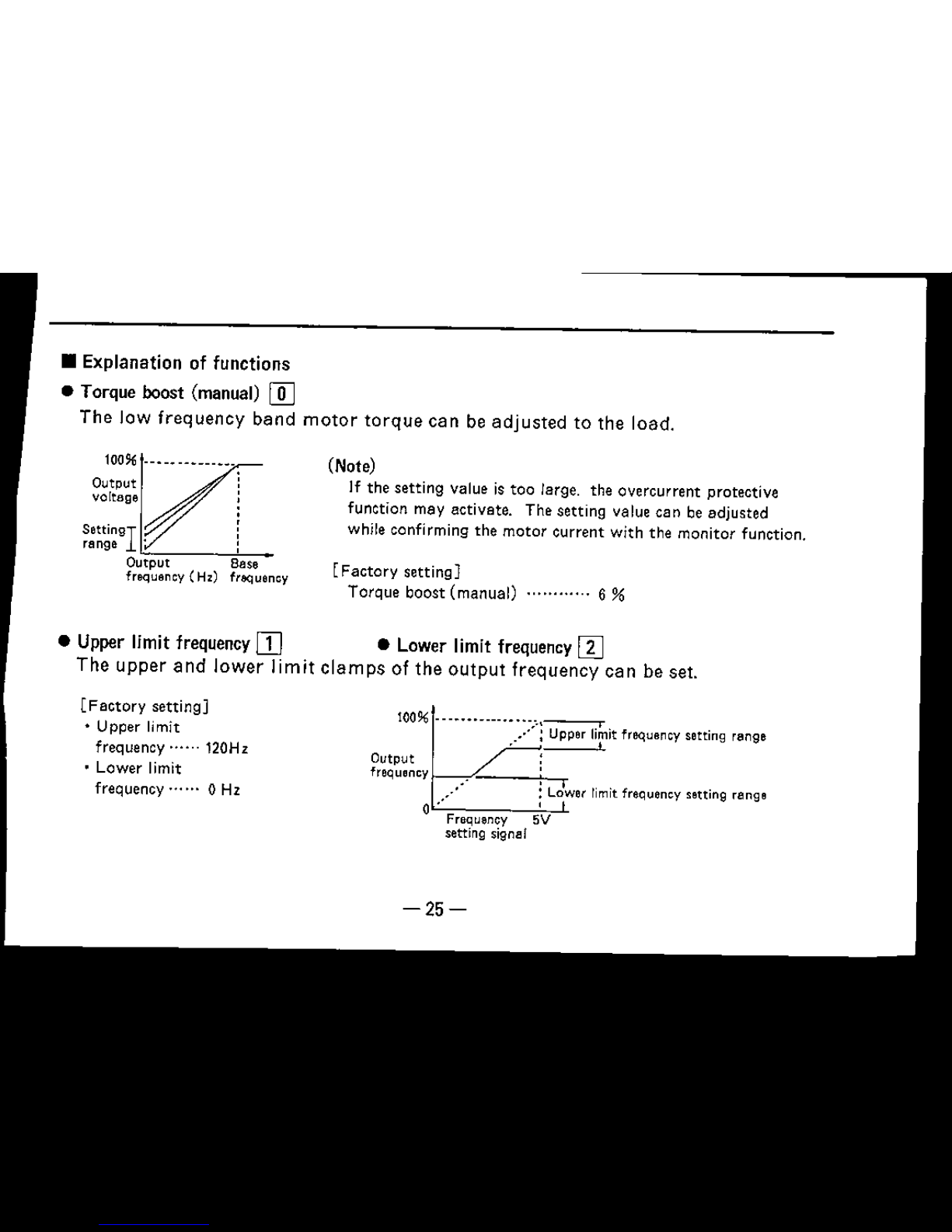
• Upper limit frequency
rn
•Lower limit frequency
rn
The
upper
and
lower
limit
clamps
of
the
output
frequency
can
be set.
• Explanation of functions
• Torque boost (manual)
[[]
The
Jaw
frequency
band
motor
torque
can
be
adjusted
to the
load.
-25-
lOO%~
'~
..•..•
:~it
frequency setting range
Output :
frequency ,
.•.••. :
Lo1wer
limit frequency setting range
o- ,
Frequency 5V
setting signal
[Factory
setting)
Torque boost
(manual)
6 %
(Note)
If
the
setting
value is
too
large. the overcurrent protective
function may activate. The setting value can be adjusted
while confirming the
motor
current
with
the
monitor
function.
[Factory
setting)
• Upper limit
frequency"""120Hz
• Lower limit
frecuencv-. ... 0 Hz
O~::~~-·----·---··-1
""""?T
Settingr
. [
range :
Output Base
frequency (Hz) frbQuency

• VIF(base frequency)
rn
The base frequency (reference frequency
at
motor
rated
power)
can be
set
freely
between 50
and
120Hz
according
to the
motor
rating.
[Factory
setting]
V/F
{base frequency) .... ···.. 60Hz
aese frequency setting fange
I 'I
Output
voltage
50 Base 120
frequency
Output
frequency (Hz)
-26-

• Acceleration time (I] • Deceleration time
[[]
• Acceleration/deceleration reference frequency
~
Pr.7
and
8 can be
set
between 0.1
and
999seconds.
Acceleration
time
is the
time
(inclination)
taken
for
acceleration
to the
frequency
(fm)
setinacc./dec.
reference
frequency
Pr.20.
If the
acceleration/deceleration
time
is set to 0, the
time
will be 0.04 seconds.
5.0sec.
5.0 sec.
[Factory
setting]
Acceleration time
Deceleration time
Acceleration/deceleration
reference
frequency··········
60Hz
Deceleration
time
W
Acceleration
time
[II
'1'--1---++....1- Time
-27-
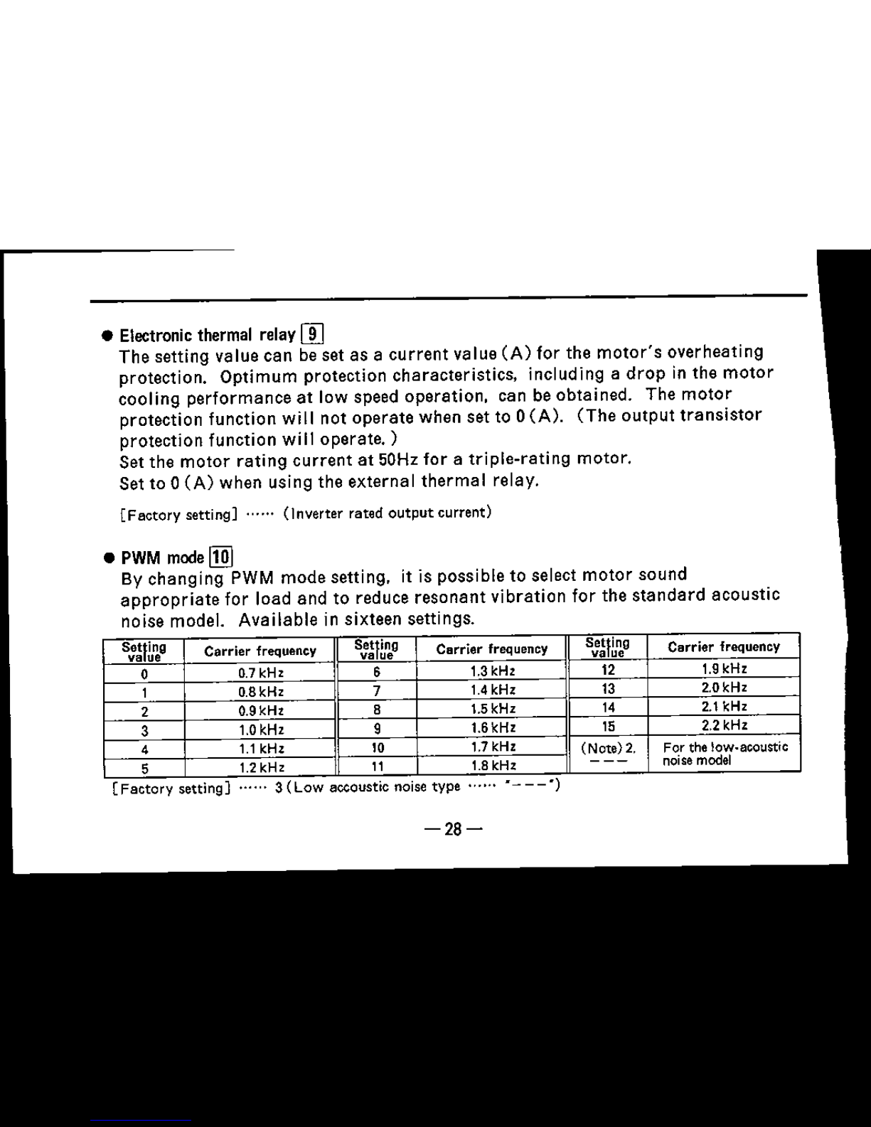
[Factory
settmg]
......3(Low
eccousnc norse
type
......
-28-
•
PWM
mode
I!ID
By
changing
PWM
mode
setting, it is
possible
to select
motor
sound
appropriate
for load
and
to reduce
resonant
vibration
for the
standard
acoustic
noise model.
Available
in sixteen settings.
• Electronic thermal relay
rn
The
setting
value
can
be set as a
current
value
(A)
for the
motor's
overheating
protection.
Optimum
protection
characteristics.
including a
drop
in
the
motor
cooling
performance
at
low speed
operation.
can be
obtained.
The
motor
protection function will not
operate
when
set
to 0
(A).
(The
output
transistor
protection
function will
operate.)
Set the
motor
rating
current
at
50Hz
foratriple-rating
motor.
Set to 0
(A)
when using the
external
thermal
relay.
[Factory
setting]
......
(Inverter
rated
output
current)
s:~n~g
Carrier frequency
S:~n~g
Carrier frequency
s::n~g
Carrier frequency
0
0.7kHz
6 1.3kHz 12 1.9kHz
1 0.8kHz
7 1.4kHz 13
2.0kHz
2 0.9kHz
8 1.5kHz 14 2.1kHz
3
1.0kHz
9
1.6kHz 15 2.2kHz
4
1.1kHz 10 1.7kHz
(Nctel
z.
For the row-acoustic
6
1.2kHz 11
1.8kHz
---
noisemodel
.
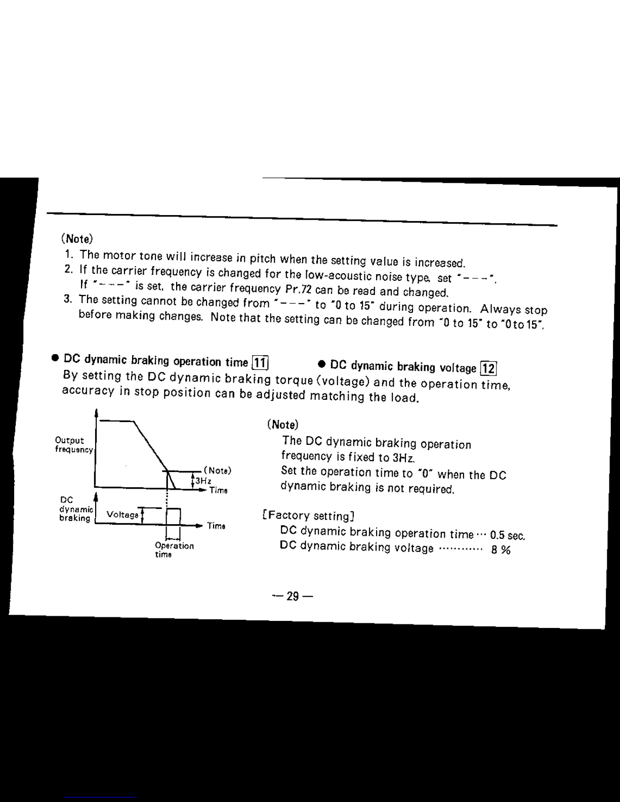
• DC dynamic braking operation
time
[1J
•
DC dynamic braking voltage
[gJ
By
setting
the
DC
dynamic
braking
torque
(voltage)
and
the
operation
time,
accuracy
in
stop
position
can
be
adjusted
matching
the
load.
(Note)
1.
The
motor
tone
will
increase in pitch when the setting value is increased.
2. If the carrier frequency is changed
for
the row-acoustic noise type. set
~
- - -:",
If
M "
is set.
the
carrier
frequency Pr.72 can be
read
and changed.
3. The setting
cannot
be changed
from
M "
to·O
to 15"
during
operation.
Always
stop
before
making
changes. Note
that
the setting can be changed
from
·0 to 15"to ·0 to 15",
Output
frequ~ncy
(Note)
3H'
L
p.......l"-'
Time
~y~a.mlc
t
Voltage-
L
braking
~
Time
U
Operation
time
(Note)
The DC
dynamic
braking
operation
frequency
is fixed to 3Hz.
Set the
operation
time
to
·0·
when the DC
dynamic
braking
is not required.
(Factory
setting]
DC
dynamic
braking
operation
time
.., 0.5 sec.
DC
dynamic
braking
voltage
8
%
-29-

• Frequencysetting voltage bias [1]
• Frequencysetting voltage gain
~
The
output
frequency
(ratio)
for
the frequency setting
signal
(DC
0 to 5V)
can
be
set freely.
Output
frequency
(Hz)
Bias
-30-
*When
setting
the
bias
and
gain.
the
frequency
setting
signal
need
not
be input.

• Stall prevention operation levle
~
An
overload
(excessive
torque)
can be prevented when
driving
a
motor
with
a
capacity
smaller
than
the
inverter
by
changing
the
stall
prevention
operation
current
level.
This
will
also
function
during
acceleration/deceleration.
The
operation
current
level is
set
with
setting
values
(codes).
Setting
Operation level
Setting
Operation level
Setting
Operation level
value
value value
,
110%
5
150%
9
190%
2
120%
6
160%
'0
200%
3
130%
7
170%
Stall
preventiqn
0
is
not
activated.
4
140%
8
180%
[Factory
setting]
.....
5
(150%)
• The
operation
level
%
indicates the
ratio
to the inverter
rated
output
current
-31-
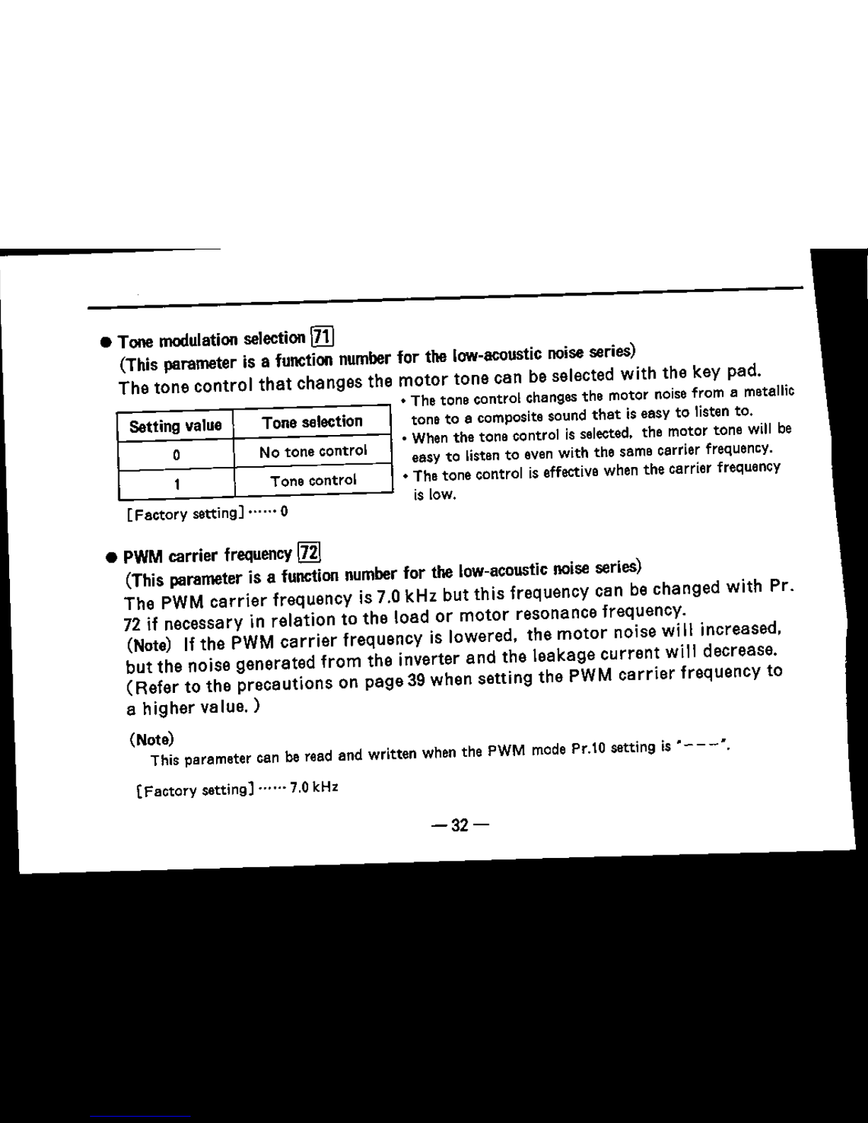
[Factory
setting] •....• 0
Setting value
Tone selection
0
No tone control
1
Tone control
• Tone modulation selection
ITIJ
(This parameter is a function numberfor the low-acoustic noiseseries)
The
tone
control
that
changes
the
motor
tone
can
be selected
with
the key
pad
.
• The tone control changes the motor noisefrom a metallic
tone to a composite sound
that
is easy to listen to.
o
When the tone control is selected. the motor tone will be
easy to listen to even with the same carrier frequency,
• The tone control is effective when the carrier frequency
is low.
•
PWM
carrier
frequency
IllJ
(This parameter is a function number for
the
low-acoustic noise series)
The PWM
carrier
frequency is 7.0 kHz
but
this
frequency can be
changed
with
Pro
72
if necessary in
relation
to
the
load or
motor
resonance
frequency.
(Note)
If
the
PWM
carrier
frequency is lowered,
the
motor
noise
wi
II increased,
but
the
noise
generated
from
the
inverter
and
the
leakage
current
will decrease.
(Refer
to
the
precautions
on
page
39 when
setting
the
PWM
carrier
frequency
to
a
higher
vefue.)
(Note)
This parameter can
be
read and written when the PWM mode Pr.10 setting is
"-
- -:",
(Factory
setting]
......
7.0kHz
-32-
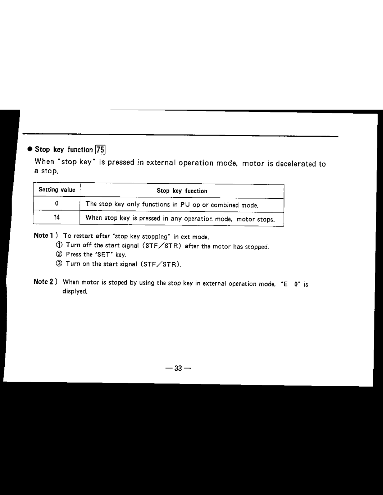
• Stop key function
IZID
When
"stop
key" is pressed in external
operation
mode,
motor
is decelerated to
a stop.
Setting value Stop key function
o The
stop
key
only
functions in PU op or combined mode.
14 When
stop
key is pressed in
any
operation
mode,
motor
stops.
Note
1)
To restart after
'stop
key stopping" in ext mode.
CD
Turn off the
start
signal
(STP/STR)
after the
motor
has stopped.
@ Press the 'SET" key.
@ Turn on the
start
signal
(STF/STR).
Note
2)
When motor is stoped by using the stop key in external operation
mode.
"E O' is
displyed.
-33-
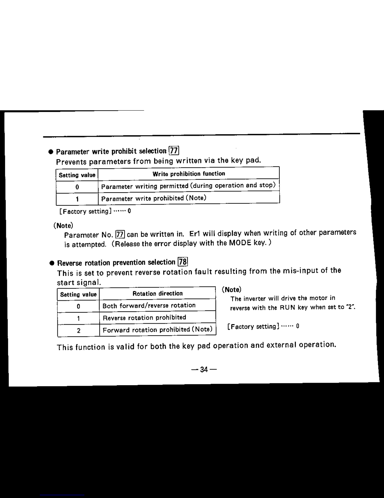
• Parameter write prohibit selection[ll]
Prevents
parameters
from
being
written
via the key pad.
Setting value Write prohibition function
0
Parameter
writing permitted (during operation and
stop)
1
Parameter
write prohibited
(Note)
[F actory setting] ..•". 0
(Note)
Parameter No. Ill]can be written in.
Er1
will display when writing of other parameters
is attempted. (Release the error display with the MODEkev.)
• Reverse rotation preventionselection
IIID
This
is set to prevent reverse
rotation
fault
resulting
from
the
mis-input
of the
start
signal
Setting value Rotation direction
0 Both forward/reverse
rotation
1 Reverse
rotation
prohibited
2
Forward
rotation
prohibited
(Note)
(Note)
The inverter will drive the motor in
reverse with the RUN key when set to
M2
M•
[Factory
setting)
......
0
This
function is
valid
for both
the
key pad
operation
and
external
operation.
-34-

• Operation
mode
selection
lZID
The
inverter
operation
modes
include
operation
with
external
signals
and
operation
with
key
pad.
Operation
can
be
limited
to one
mode
or
can
be
carried
out
with
both
modes.
Setting value 1 Operation only
with
key pad
Setting value 2 Operation
only
with
external signals
Setting value 3
Operation trecuencv-: Set with key pad (direct setting or
~l!J
keys)
Start
signal",
External signal
input
(STF.
STR
terminals)
Setting value 4
Operation
frequency""
External
signal
input
(DCOto5V between
termtnalsz-s)
Start
signal'"
Input
with
key pad
(RUN
key)
(Note)
4.
[Factory
setting) 1
(Note)
1.
This
parameter
cannotberewritten
during
operation. Er2
will
display if
writingisattempted.
2. Setting values 3 and 4 are set to use the external signals and key pad operation for the
operation frequency setting and
start
signals.
3. When set to 3, the operating frequency is set via key pad and analog signa! input is ignored.
4. When set to 4, the operating frequency is set via analog signal input.
-35-
-36-
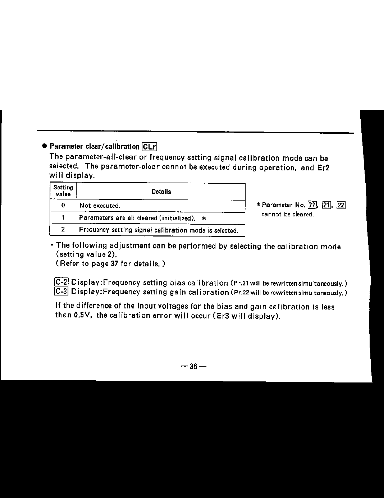
• The following
adjustment
can be
performed
by selecting the
calibration
mode
(setting
value 2),
(Refer
to
page37for
details.)
• Parameter clear/cali'bration
ICLrl
The
parameter-all-clear
or frequency
setting
signal
calibration
mode
can be
selected. The
parameter-clear
cannot
be executed
during
operation.
and
Er2
will
display.
*Parameter No.lllI,
1m,
~
cannot be cleared.
~
Display:Frequency
setting
bias
calibration
(Pr.21 willberewrittensimultaneously. )
~
0 isplay:Frequency
setting
ga in caIi
bration
(Pr.22 will be rewritten slmultenecuslv,)
If the difference of the
input
voltages
for
the
bias
and
gain
calibration
is less
than
O.5V,
the
calibration
error
will occur
(Er3
will
display).
Setting
Details
value
0 Not executed.
1
Parameters are all cleared (initiefieed).
*
2
Frequency setting signal calibration mode is selected.

o Example of parameter-all-clear!calibration operation
Selection of
setectlcn
Read
out
Change
to 1
Write
in
display
mode
of function
of
current
number
value
0
Parameter-clear
[SIT]
Koy
!MODEI
......
IMODEI
-
~ -
[ill]
operation
ICL,-I
Display
1'-"01
Ip
01
lCL,·1
c::::m
0
A
Displays
0 ...•.
+
elternately
0
To
change
Pr.C-2
from
0 Hzto3 Hz,
Write
in
Read
out
of
Change to
Change
to 2
(Select
Write
in
Chang
calibration
current
value
3H,
mode)
..
Changes
Output
4
0
0
ISETI
I
SETI
frequency
o
whil~
h~td
ISETI
(Hz)
down
IC-,?I
3
Q
Ic-.?\
c::::m
OJ
t
~1;:~~':I:IY
OJ
0
Frequency setti
signal
-37-
09

Gain
If-'
i
NOU
)
,v
frequenoy setting signal
(Note)
• When this C-2 or C-3 is specified, value set for 'frequency setting voltage bias"
(function No. 21)
or
'frequency setting voltage
gain-
(function No.22) will be
automatically
rewritten.
-38-
• Frequency setting bias calibration §
• Frequency setting gain calibration
fC=3l
Allows
the
output
frequency
to be
set
in
relation
to
the
frequency
setting
signal
(DC
Oto
5V).
(Bias)
The
output
frequency
for
the
setting
signal
input
between
terminals
2-5
will
be set.
(Gain)
The
output
frequency
for
the
setti
ng sig naJ
input
between
term
ina
Is 2-5 wi II be
set
If
the
input
signal
is
av,
it is
judged
to be 5V
input.

To set frequency with
current
input
(4 to 20mA)
(60Hz)
--------------
. ,
,
,
,
/ 1
/'
L
When4to!
~20mAis
,
;'
used I
Fa~tory
setting
Output
fr&quen~y
(Hz)
2.
Adjust
C-2
(bias)
as below.
(Pr.21 will be
rewritten
simultaneously.)
1. Place a
resistor
between 2-5.
and
convert
the
current
into a voltage. (4 to
zoma->
1 to 5V)
Install a resistor
(2500
lW)
(-)-~-=:~
(+
)1-----,,..1
Remarks
1
(4)
5V
(20mA)
-39-

)PrecautionsI
1. It is necessary to accept a reduction of load torque when
setting the
PWM
carrier
frequency to a higher value.
PWM carrier frequency (kHz)
o
2.37
8
910
11
12131414.5
-~-Ijl-.
-.-~-.~
- r-,-
-.-
-0_
-~- - -
-.-
- r _
0.-.
_..-~-
=:=
=~=~==
=~
---
.~
100
-;--""
'l!
li
~
60
SO
Derating
to rated
current
(%)
-40-
(1)
When setting the PWM
carrier
Ireq uenoy
(Pr
.72) to 7.1kHz or
more
to lower the
motor
acoustic
noise, the rated
output
should
be derated as
shown
on the right.
Also change the electronic
thermal
relay
(Pr.
9) setting.
(2)
If the PWM
carrier
frequency
is increased, the
acoustic
noise from the
motor
will
lower, but the noise qenerated
by the inverter
and
the leakage
current
will increase.

2. Noise
Thereisnoise
that
enters
from
outside
and
causes
the inverter to
malfunction
and
that
which is
generated
from
the
inverter
and
causes
the
peripheral
equipment
to
malfunction.
The inverter is
designed
so
that
it is not
easily
affected by noise.
but
as it is
an
electronic
device which
handles
weak
signals.
the
following
general
countermeasures
will be
required.
+General
countermeasures
• Avoid
laying
the
inverter's
power
cables
(input/output)
in
parallel
with
the
signal
wires
and
avoid
bundling
the
power
cables
and
signal
wires.
• Use
twisted
pair
shield
wires
for
the
connection
wires
with
the
sensor
and
for
the
control
signal
wires.
Connect the
sheath
of the
shield
wire
to
terminal
SO.
• Use
one-point
grounding
for
the inverter
and
motor.
etc.
-41-

+Example
of noise
countermeasures
Motor
Sensor
Use a s-ecre cable for the
motor power cable, and use
one wire for the grounding.
Install a filter (FR·BSFOl)
on the inverter
output
side.
Do not ground the shield,
but instead
connllGt
to the
common wirefor the signals.
Use twisted pair shield wires.
lower
carrier
frequency
Do not
dirllGtly
ground
to the control panel.
~~
:~t~~e~];e.9rOund
'-_"'-
-'tJ
Separate the inverter
unit",
....
_
power cables and sensor
circuit by
30cm
or more
(at
least
lDem).
Install a filter
(FR.BSFOl) on the
Power _ inverter input side.
supply-o
Install a fHur
(FR.
elF)
on the
inverter input side
Control
panel
-42-

3. Leakage
current
Leakage
current
will
flow
through
stray
capacity
which
exists
between the
ground
and
a cable,
motor,
etc. The
value
of the
leakage
current
depends
on the
cable
length,
wiring
method
and
inverter
carrier
frequency, and will
increase
when
using
a
low-acoustic
noise inverter, so use the
following
countermeasures.
(1)
Leakage
current
to the
ground
The
leakage
current
will not
affect
only
the
inverter
but
may
pass
into
other
equtpments
through
the
grounding
cables
and
may
cause
a
leakage
breaker
or
relay
unnecessary
trip.
_Countermeasures
Route
of
leakage
current
•
Lower
the
inverter's
carrier
frequency
(Pr.
72). Note
that
this
will
increase
the
motor
acoustic
noise
.
• Use a
leakage
breaker
that
corresponds
to high
harmonics
and
surges
(Mitsubishi
New
Super
NV Series,
etc.)
for the inverter
or
other
lines
when
using
the
low-acoustic
noise model
(with
high
carrier
frequency).
-43-
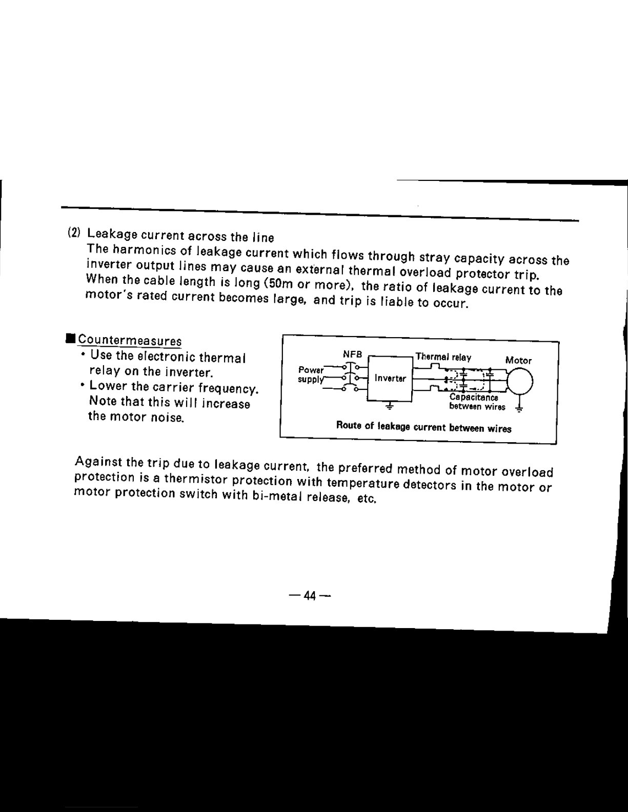
(2)
Leakage
current
across
the line
The
harmonics
of leakage
current
which flows
through
stray
capacity
across
the
inverter output lines
may
cause an external
thermal
overload protector trip.
When the cable length is long (50m or more), the
ratio
of leakage
current
to the
motor's
rated
current
becomes large.
and
trip
is liable to occur.
• Countermeasures
• Use the electronic
thermal
relay on the inverter.
• Lower the
carrier
frequency.
Note
that
this will increase
the
motor
noise.
NFB
The~al
relay
M~r
power~
Inverter
.)
,
SUPPIC""O-
'
_
....
Capacitance
T
between
wires ':'
Routa of leakage current between wires
Against
the
trip
due to leakage current, the preferred method of
motor
overload
protection is a
thermistor
protection with
temperature
detectors in the
motor
or
motor
protection switch with bi-metal release, etc.
-44-

4. Carrier frequency
The parameter of carrier frequency (Pr.l0) must be changed for the operation
frequency range as following:
Operation frequency range
Pro
10 setting value
0.5 to 77 Hz
oto 15.
---
0.5 to 88 Hz
1 to 15.
---
0.5 to 99 Hz
2 to 15.
---
0.5 to 111 Hz
3 to
15.
---
0.5 to 120 Hz
4 to
15.
---
-45-
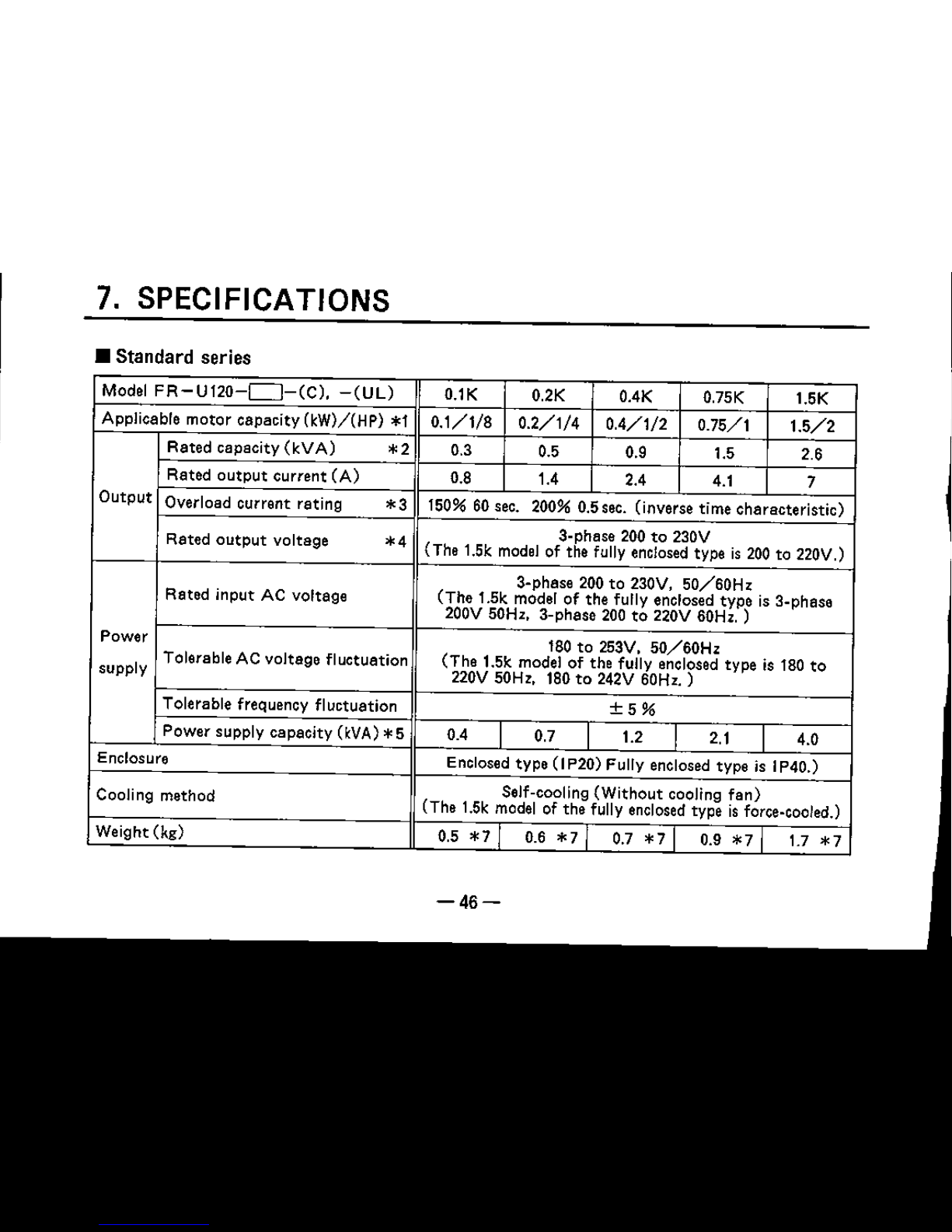
7. SPECIFICATIONS
• Standard series
Model
FR-U120-C]-(C).
-CULl
O.1K
0.2K 0.4K
a.75K
1.5K
Applicable
motor
capacity
(kW)/(HP)
*1
0.1/1/8 0.2/1/4 0.4/1/2
0.75/1
1.5/2
Rated
capacity
(kVA)
*'
0.3
0.5
0.9 1.5 2.6
Rated
output
current
(A)
0.8
1.4 2.4
4.1
7
Output
Overload current rating
*3
150%60sec. 200% 0.5sec. (inverse time
characteristic)
Rated
output
voltage
*4
a-pheee 200to230V
(The 1.5k model of the fully enclosed type is 200 to 220V.)
a-phase 200 to 230V,
SO/60Hz
Rated
input
AC
voltage
(The
1.5k model of the fully enclosed
typeisa-phase
200V 50Hz, 3-phase 200to220V 60Hz. )
Power
180to253V.
SO/60Hz
supply
Tolerable AC
voltage
fluctuation
(The
1.5k model of the fully enclosed type is 180
to
220V 50Hz, 180to242V 60Hz. )
Tolerable frequency
fluctuation
±5%
Power
supply
capacity
O:VA)
*5 0.4
0.7
I
1.2 2.1
4.0
Enclosure
Enclosed
type
(I P20) Fully enclosed type is IP40.)
Cooling method
Self-cooling
(Without
cooling
fan)
(The 1.5k model of the fully enclosed type isforce-cooled.)
Weight
(kg)
0.5
*7
0.6
*7
0.7 * 7 I
0.9
*7
1.7
*7
-46-
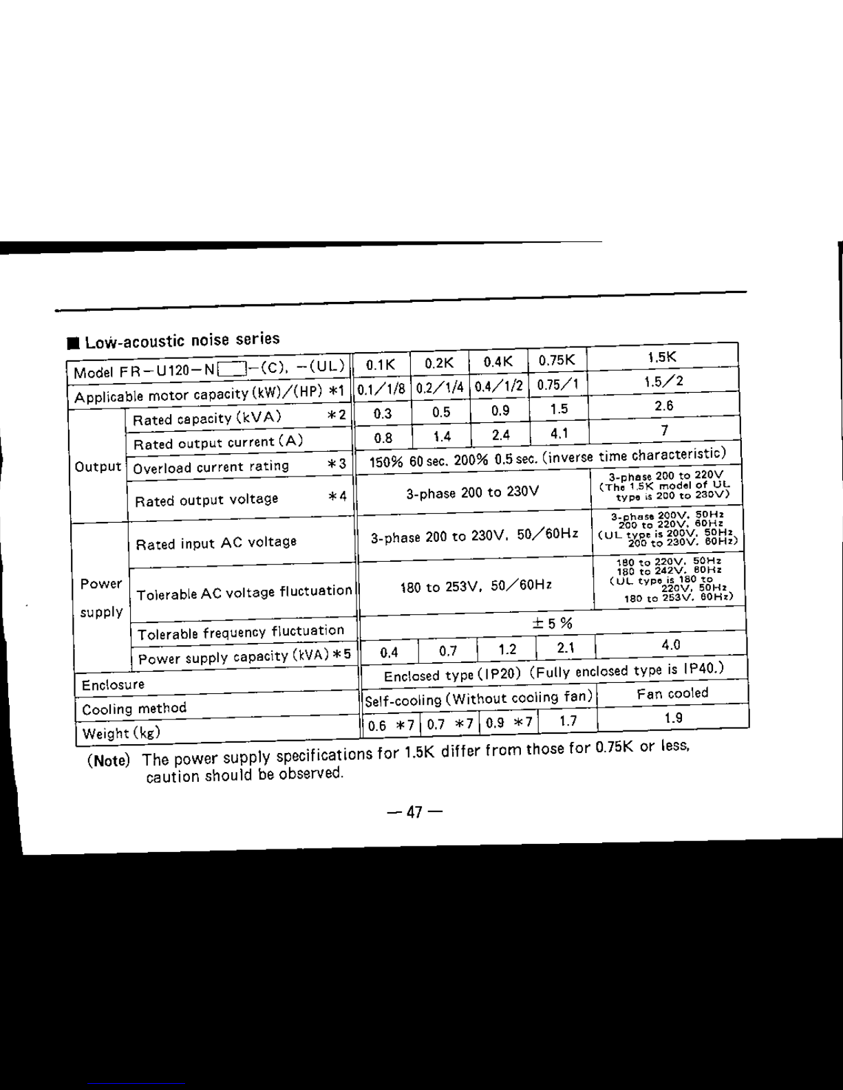
• Low-acoustic noise series
Model
FR-U120-ND-(C),
-(UL)
0.1K
0.2K
0.4K 0.75K 1.5K
Applicable
motor
capacity (kW)/(HP) *1
0.111/8
0.2/1/4
0.4/1/2
0.75/1
1.5/2
Rated
capacity
(kVA)
*2
0.3 0.5 0.9 1.5
2.6
Rated
output
current
(A)
0.8 1.4 2.4 4.1
7
Output
Overload current rating
*3
150% 60sec. 200% 0.5sec.
(inverse time characteristic)
a-cbe
se
200
to
220V
Rated
output
voltage
*4
3-phase 200 to 230V
(Tho
1,5K
model
of
UL
typo
is
200
to
230V)
3_p!'>as.200V.
50Hz
Rated
input AC voltage
3-phase 200 to 230V,
SO/60Hz
200
to
220V.
60Hz
(UL
typo
is
200V.
50Hz
200
to
230V.
60Hz)
Power
vee
to
220V.
50Hz
180
to
242V.
60Hz
Tolerable AC voltage fluctuation 180 to 253V.
50/60Hz
(UL
typo
is 180
to
220V,
50Hz
supply leo
to
253V.
80Hz)
Tolerable frequency fluctuation
±5%
Power
supply capacity (kVA)
*5
0.4
0.7 1.2 2.1 4.0
Enclosure
Enclosed type
(IP20)
(Fully enclosed type is IP40.)
Cooling method
Self-cooling
(Without
cooling
fan)
Fan
cooled
Weight (kg) 0.6
*7
0.7
*7
0.9
*7
1.7
1.9
(Note) The power supply specifications
for
1.5K differ
from
those for
a.75K
or
less.
caution should be
observed.
-47-
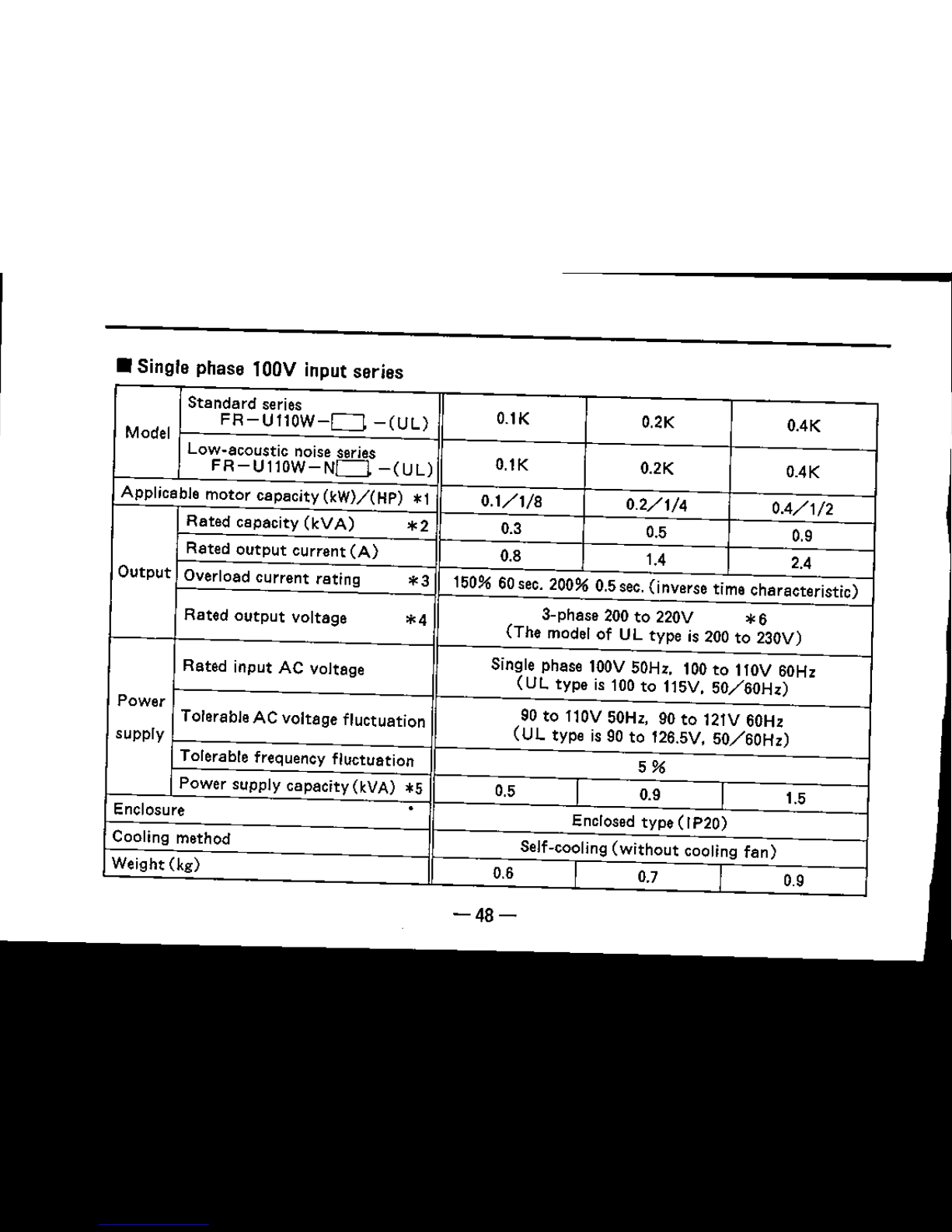
• Single phase lOOV input
series
Standard
series
O.IK
0.2K 0.4K
Model
FR-Ull0W-D
-CUL)
Low-acoustic noise series
O.lK 0.2K OAK
FR-Ull0W-ND
-(UL)
Applicable motor capacity
(kW)/(HP)
*1
0.1/1/8
0.2/1/4
0.4/1/2
Rated capacity
(kVA)
*2
0.3 0.5 0.9
Rated
output
current
(A)
0.8 1.4
2.4
Output
Overload current rating
*3
150% 60sec. 200% 0.5sec.(inverse time characteristic)
Rated
output
Voltage
*4
3-phase 200
to
220V
*6
(The model of UL type is 200 to 230V)
Rated input AC voltage
Single phase 100V50Hz. 100
to
110V 60Hz
(UL
type is 100 to 115V.
50/60Hz)
Power
90 to 110V 50Hz, 90
to
121V 60Hz
Tolerable AC voltage fluctuation
(UL
type is 90 to 126.5V,
50/60Hz)
supply
Tolerable frequency fluctuation
5%
Power supply capacity
(kVA)
*'
0.5
I
0.9
1.5
Enclosure
Enclosed type
(rP20)
Cooling method
Self-cooling
(without
cooling
fan)
Weight (kg)
0.6
0.7
0.9
-48-
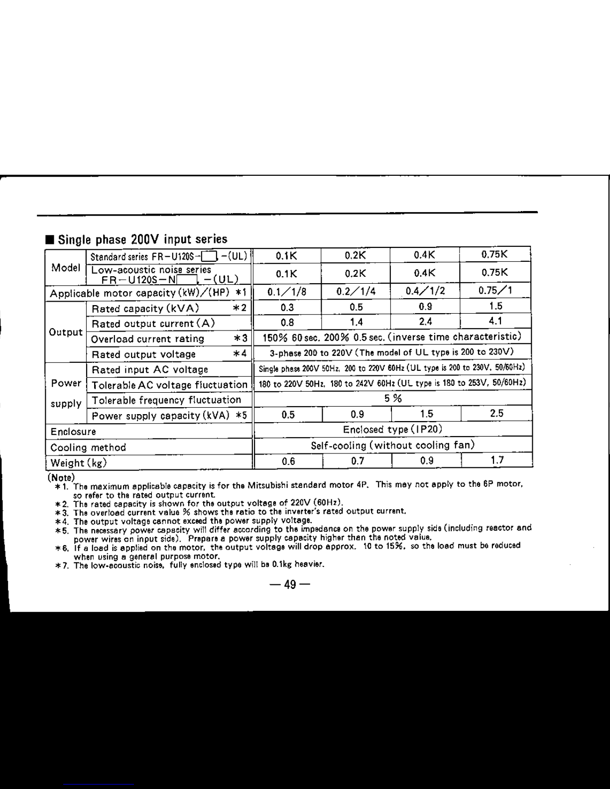
• Single phase 200V input
series
IStandard series FR
U120S
0 (UL)
O.lK
O.2K OAK
O.75K
Model
Low-acoustic
no~s~ie~
(I 1 )
O.1K
O.2K OAK
0.75K
FR-U120S-N
- UL
Applicable
motor
capacity
(kW)/(HP)
* 1
0.1/1/8
0.2/1/4 0.4/1/2
0.75/1
Rated
capacity
(kVA)
*2
0.3
0.5 0.9 1.5
Rated
output
current
(A)
0.8
1.4 2.4 4.1
Output
Overload
current
rating
*3
150%
60 sec.
200%
u.s
sec.
(inverse
time
characteristic)
Rated
output
voltage
*4
s-pnese
200 to 220V (The model of UL type is 200 to 230V)
Rated
input
AC
voltage
Single
ohese
200V
50Hz.
200to zarv
60Hz
(ULtype~200
to
230V,
50/60Hz)
Power
Tolerable
AC
voltage
fluctuation
180to 220V
SOHz,
180to 242V
60Hz
(UL type is180to 253V, 50/60Hz)
supply
Tolerable
frequency
fluctuation
5%
Power
supply
capacity
(kVA) *5
0.5
I
0.9
I
1.5
I
2.5
Enclosure
Enclosed
type(IP20)
Cooling
method
Self-cooling
(without
cooling
fan)
Weight
(kg)
0.6
I
0.7
I
0.9
I
1.7
(Note)
*1. The maximum applicable capacity isfor the Mitsubishi standard motor 4p, This may not apply to the 6P motor.
so refer to the rated
output
current.
*2. The rated capacity isshown for the
output
voltage of 220V (60Hz).
*3. The overload current value
% shows the ratio to the inverter's rated
output
current.
*4. The
output
voltage cannot
exceed
the power supply voltage.
*5. The necessary power capacity willdiffer according to the impedanceon the power supply side(including reactor and
power wires on input side). Prepare a power supply capacity higher than the noted value.
*6. If a load isapplied on the motor. the
output
voltage will drop approx. \0 to 15%. so the load must be reduced
when using a general purpose motor.
*7. The lcw-ecoustio noise. fully enclosedtype
wl11
be O.lkgheavier.
-49-
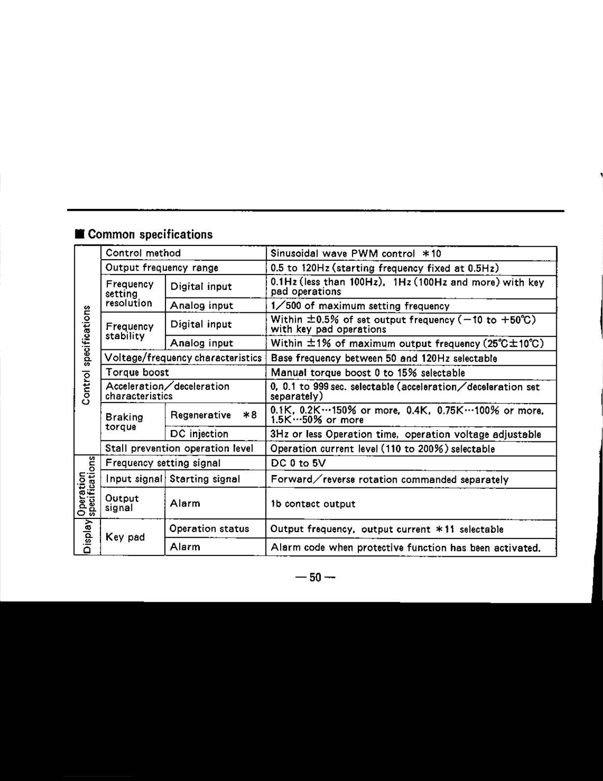
• Common specifications
Control method Sinusoidal wave PWM control
*10
Output
frequency range
0.5 to 120Hz
(starting
frequency fixedat0.5Hz)
Frequency
Digital input
0.1Hz (less
than
100Hz).
1Hz (100Hz and more) with key
setting
pad operations
"
resolution
Analog input
1/500
of maximum setting frequency
0
Within
±0.5%
of set
output
frequency (
10 to +50OC)
0
Digital input
.~
Frequency
with key pad operations
~
stability
Analog input
Within
+1%
of maximum
output
frequency (25°C±10°C)
g
Voltage/frequency characteristics Base frequency between 50 and 120Hz selectable
~
e
Torque boost
Manual torque boost 0 to 15% selectable
"
Acceleration/deceleration 0.0.1 to 999sec. selectable (acceleration/deceleration set
0
characteristics separately)
u
0.1K.
O.2K
"'150% or more.
OAK,
0.75K···100% or more.
Braking
Regenerative
*8
1.5K
"'50%
or more
torque
IDC injection
3Hz or less Operation time, operation voltage adjustable
Stall prevention operation level
Operation current level(110 to 200%)selectable
"
Frequency setting signal
DC 0 to 5V
0
0
.~~
Input signat Starting signal
Forward/reverse
rotation commanded separately
i;:'u
Output
Alarm 1b contact
output
~.
signal
o~
>
•
Operation
status
Output frequency.
output
current *11 selectable
~
Key pad
i5
Alarm
Alarm code when protective function has been activated.
-50-

Overcurrent
shut
down
(during
acceleration/deceleration/
Protection/warning
function
constant
speed), regenerative overvoltage
shut
off.
electronic thermal overload. stall prevention
Ambient temperature
-10
to +50°C
(-10
to +40°C for
totally
enclosed
type)
(with
no freezing)
»,
Ambient humidity 90% RH or less
(with
no dew condensation)
•
fr
Storage
temperature
*9
-20
to +65°C
is
Indoors
with
no corrosive or flammable gases. oil mist or
Atmosphere
dust
Altitude/vibration
Less
than
1000m above sea level.
5.9m/S'(O.6G)
or less
-51-
1,000
5,000
HP
rating
o to ,
(Note)
*8.
The braking torque shows the
short
time average deceleration torque when the motor
without
load is decelerated in the shortest time from 60Hz (changes due to motor's loss), and is not
the continuous regenerative torque. For deceleration from a frequency
that
exceeds the base
frequency. the average deceleration torque value will decrease.
A brake resister is not built-in and
cannot
be extemally installed.
1.5K is not available for the single phase input series.
*9. This is a
short
time temperature
for
during transportation, etc.
*10. The low-acoustic noise series use the high carrier frequency sinusoidal PWM control.
*11. The
output
current is displayed only while the SET key is being pressed.
*12. Short Cirunit Ratings
The drive is suitable
for
use on a circuit capable of delivering not move
than
* RMS
symmetrical Amperes.
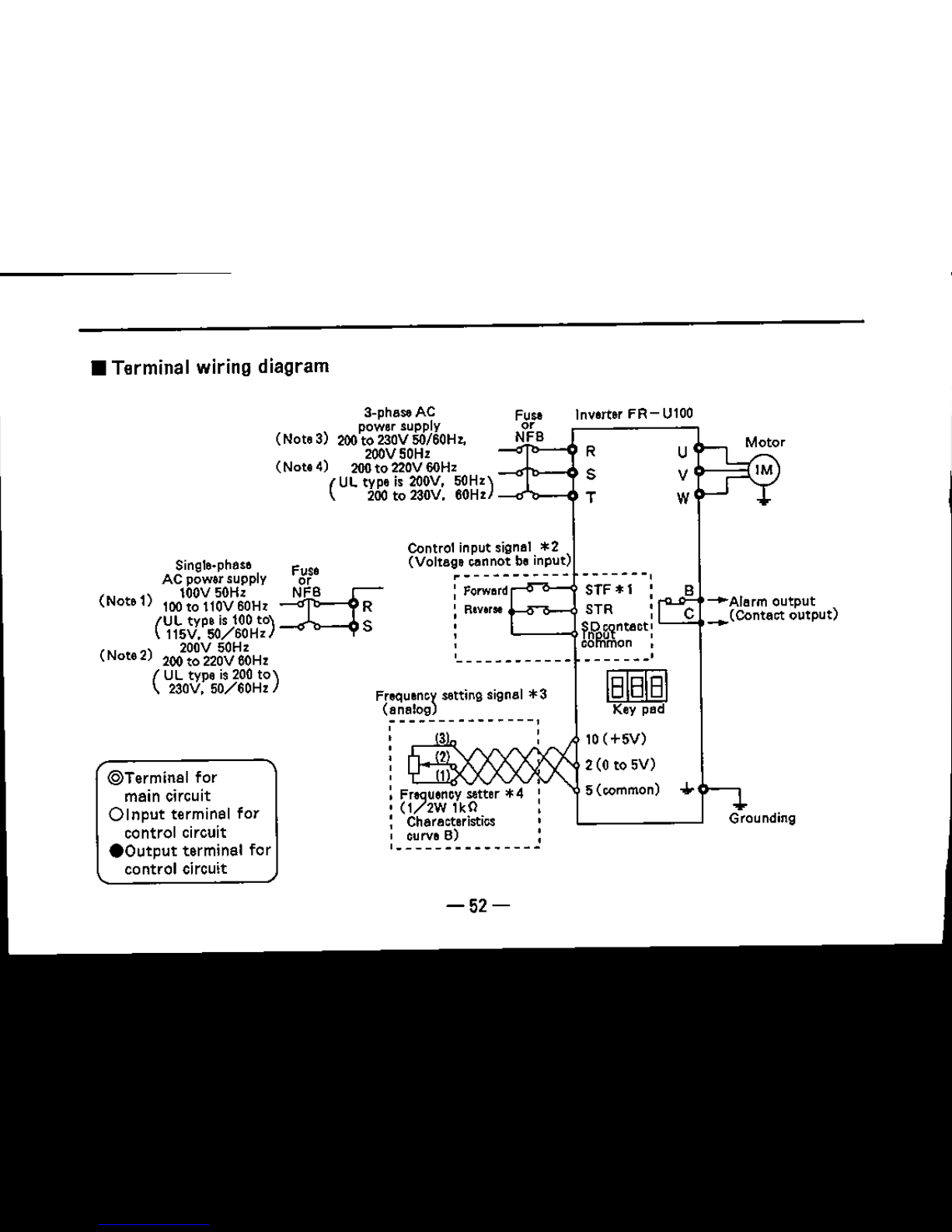
•
Terminal
wiring
diagram
Inverter
FR-U100
F".
0'
NFB
3-phase AC
(Note 3)
2OO~~";;~Vu:)$OHl,
2OOV50Hz
R
(Note 4) 200to 220V60Hz
(
UL tYpe is 200V. 50HZ)
S
200to 230V. 60Hz
_-"'_--<10
T
u
V
W
Motor
1M
Control input signal
*2
(Voltage cannot be input)
~-----------
-------,
:
Forwerd
STF *1 :
:
Rlverse
l-
..........J STR '
,
frPra
ntact
:
, common
I
,
------------
B
-e-Aterm
output
C
_(Contact
output)
Grounding
mill]
Key pad
10(+5V)
2(Oto5V)
5 (common)
FreqUenC\
setting signal
*3
(analog
~--------------'
: 3 :
, 2
: 1
: Frequencysetter *4
,
(l/2W
1kO
: Characteristics
, curve B) :
,---------------
@Terminal
for
main circuit
Olnput
terminal
for
control circuit
.Output
terminal
for
control circuit
Single-phase fuse
AC power supply or
)
100V50Hz
~FB
(Note 1 100to 110VSOHz R
(
UL type is 100to)
S
115V. SO/SOHz
(Note2)
2oo2~~~2g~OOHZ
(
UL type is 200
to)
230V.
50/S0Hz
-52-

*1. Short-circuit between
terminals
STR-SO to
perform
reverse
rotation
with key pad
operation. When Pr.78 is set to
M2
M
(forward
rotation
prohibited), the
motor
will
rotate
in the reverse direction
with
the key pad operation even if STR-SO
are
not
short
circuited. (When Pr.79 is 1 or 4)
*2.
Valid when
parameter
No.79 is set to
M2"orM3"
via key pad.
*3.
Valid when
parameter
No.79 is set to "2" or
M4"
via key pad.
*4.
2W1kQ is recommended if the frequency setting is to be changed frequently.
(Note1)For
single phase l00V power input series.
(Note2)For
single
phase
200V power input series.
(Note
S) When using the low-acoustic, fully enclosed
type
series, or O.lK to
O.75K
models of the low-acoustic noise. fully enclosed
type
series.
(Note
e) When using the low-acoustic noise. fully enclosed
type
or 1.5K model of
the low-acoustic noise, fully enclosed
type
series.
-53-

• Explanation of terminal specifications
Terminal symbol
Terminal name
Details
R, S, T
AC power input
Connect to a commercial power supply.
terminal
Main
U,V,W
Invereer
output
Connect a 3-phase motor.
circuit terminal
-.L
Grounding terminal
Ground for inverter body. Ground this.
Forward
rotation
Contact input terminal for the
forward
run command.
STF
starting
terminal
The motor will
forward
rotate
when
STF·SD
are
short
circuited, and will stop when released.
Reverse rotation
Contact input terminal for the reverse run command.
STR
starting
terminal
The motor will reverse
rotate
when
STR-SD
are
short
circuited, and will
stop
when released.
Control
Contact
input
Common terminal for the contact input signal.
circuit
SD
This is not insulated from the frequency setting input
(I npu't
common terminal
common terminal 5.
signal)
Power supply
,.
temtnet for DC5V.
Tolerable load current 10mA.
frequency setting
Frequency setting
OUtput frequency will be the maximum when DC 5V is
2
terminal
input, and the
input/output
will be in proportion.
(Voltage signal)
1nput resistance
: 10kQ
Max. tolerable input
voltage:
10V
-54-

Terminal symbol Terminal name Details
Control
Frequency
setting
circuit
Common terminal for the frequency
setting
signal.
(Input
5
input
common
This is
not
insulated from
the
contact
input
common SD.
signal)
terminal
Control
1b
contact
output
that
indicates
that
the inverter protection
circuit
Alarm
output
circuit has functioned and
output
has stopped.
8, C B-C opened during
alarm
(Output terminal
B-C closed during normal
operaflcn
signal)
Contact
capacity
AC230V O.3A.
DC30V O.3A
The
terminals
are
screwless
type. so
prepareasmall
flat-tip
screwdriver
(tip
width
2.5 to
3mm)
before
wiring.
-55-
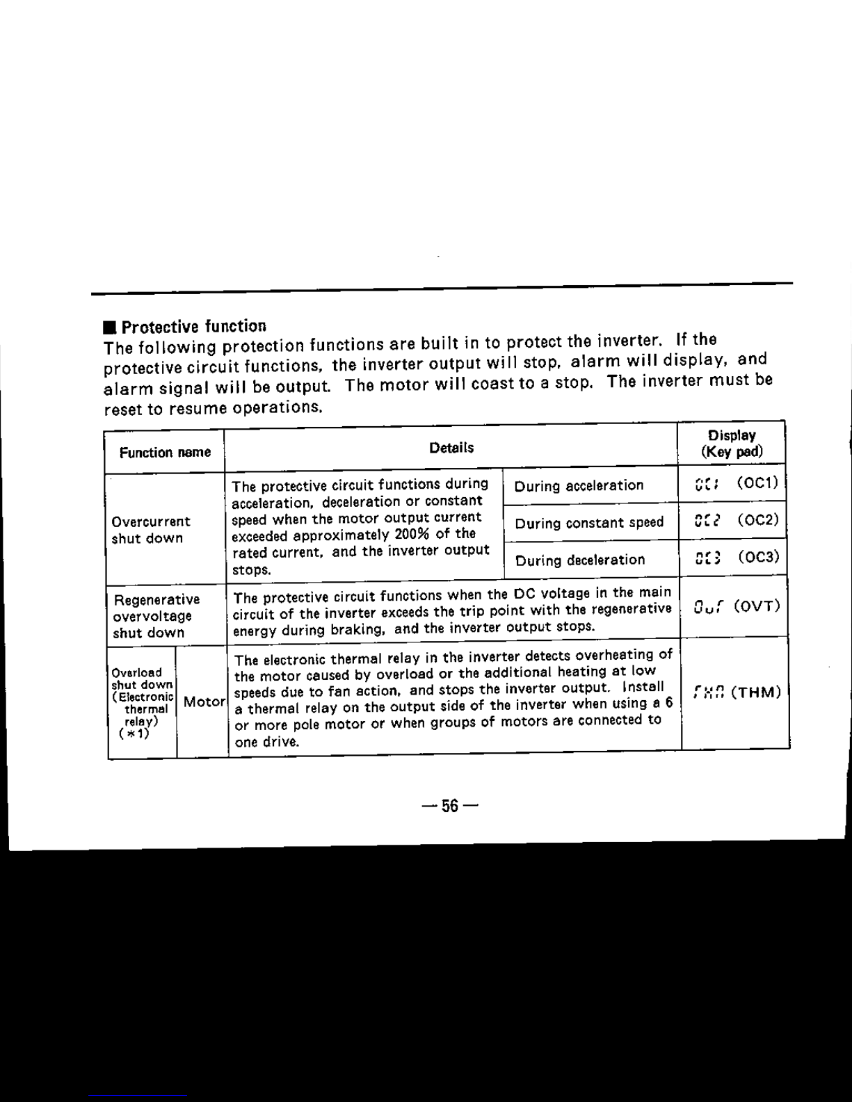
• Protective function
The following
protection
functions
are
built in to
protect
the inverter. If the
protective
circuit
functions.
the
inverter
output
will stop,
alarm
will
display,
and
alarm
signal
will be
output
The
motor
will
coast
to a stop. The inverter
must
be
reset to
resume
operations.
Function name
Details
Display
(Key pad)
The protective circuit functions during
During acceleration
~,~
,
(OCl)
acceleration, deceleration or
constant
""
Overcurrent speed when the motor
output
current
During
constant
speed
cr,
(OC,)
shut
down exceeded approximately 200% of the
rated current, and the inverter
output
During deceleration
"n
(OC3)
stops. "
....
Regenerative
The protective circuit functions when the DC voltage in the main
overvcltaae
circuit of the inverter exceedsthe
trip
point with the regenerative
n
r
(OVT)
c c ,
shut
down
energy during braking, and the inverter
output
stops.
Overload
The electronic thermal relay in the inverter detects overheating of
shut down
the
motor
caused by overload or the additional heating
at
low
(
Electronic
Motor
speeds due to fan action, and stops the inverter
output.
Install
f:.:r:
(THM)
thermal
a thermal relay on the
output
side of the inverter when Using a 6
relay)
or more pole motor Or when groups of motors are connected to
(*
1)
one drive.
-56-

Function name Details
Display
(Key pad)
Overload
The electronic
thermal
relay functions
with
the inverse
time
shut down
(Electronic
ln-
characteristictoprotect
the
output
transistor
when 150% or
r ,, ..
(THT)
thermol
verter
more of the inverter
rated
output
current
flows
but
the
'
,-"
retev)
overcurrent
shut
downisnot
activated
(under
200%).
(*
1)
EEPROM
The
output
will
stop
when
the
EEPROM
which
stores
the
PE
(PE)
breakage
parameter
set values breaks.
When 150%
(*2)
or more of the inverter
rated
current
flows
to
the
motor
during
acceleration (or
constant
speed
operation),
this
function
stops
increasing of frequency
(or
reduces frequency)
until the load
current
decreases,
to
prevent the inverter
from
n,
r
(OL
T)
overcurrent
tripping. When the load current has decreased below
""
Stall prevention
150%,
this
function
allows
the
invertertoreturntoand
continue
Whon
stopped
the
previous
operation.
During deceleration, in contrast, if DC
dueto this
voltage
in the
inverter
exceeds the rated value, this function
function
from 0
stops
reducing frequencytoprevent
the regenerative
overvoltage
constant
speed
shut
off
from
being
activated.
When the regenerative energy
operation.
becomes low,
this
function
continues deceleration again.
Insufficient
The control circuit will
not
function properly if the inverter
power
voltage
voltage
drops, and will
also
cause an insufficient
motor
torque
warning
and
increased
heat
generation. The inverter
output
will
stop
whe
,-"",
(UV)
(*3)
the
power
voltage
drops
below
approx.
AC 115V.
Operation
will
resume when the
power
voltage
is restoredtoa
correct
value.
-57-

(Note)
*1.The heat cumulative
data
in the electronic thermal relay will be initialized when the inverteris reset
*2.
The stall prevent operation current can be set freely. The default setting is 150%.
*3. An
alarm
signal will not be
output
when this protective function activates. If the voltage is
insufficient
(main
circuit DC voltage is 23DVor less) when
the
power Is
turned
on. ·0 [; . will
display for approximately 10 seconds and then the insufficient voltage display "Uu ..will appear.
(No
key pad operation will be accepted during the display
of'O
.a
",)
If
the
main circuit DC voltage is higher
than
standard
tolerance when the power is
turned
on,
the
display
·,crU
•will appear. and if the voltage does not lower within 10 seconds,
the
display
" r
• U
'.JI
• (cvervclteae
shut
down) will appear.
-58-

• Retention of alarm output signal
If the no-fuse
breaker
on the
inverter's
power
supply
side
is
turned
OFF when the
protective
function
activates, the inverter
control
power
supply
will be lost,
and
the
alarm
output
will
not
be held. If the
output
must
be held,
create
a sequence
that
will hold the
alarm
output
signal
with an
external
equiqment.
• Alarm display
The
display
on the key
pad
will
automatically
change
when the protective
function
operates.
(Only
during
rnonitor
inq.)
• Resetting methods
The inverter
output
stop
state
will be
retained
if the protective function
operates,
and
the inverter will not
restart
unless it is reset.
Turn
the
power
off
and
on once
or
press
the
RESET
key on the key pad. If the RES
terminal
is set with
Pr.BO
(input
terminal
function
selection), resetting will be
possible
by
opening
reset
terminal
RES-SD
after
short-circuiting
for
approximately
0.1 second
or
more.
If
the
short
circuited
state
between
terminal
RES-SD is continued,
OJ
{-rLf
"will
display
(light)
and
indicate
that
the reset
state
has
been
entered
-59-
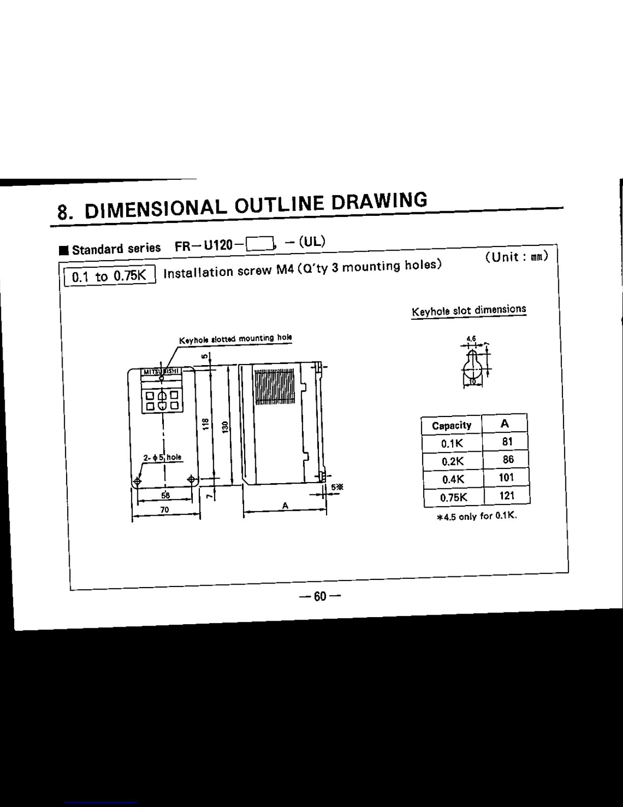
8. DIMENSIONAL OUTLINE DRAWING
• Standard series
FR-
u12o-D
-
(UL)
I
a.1
to
a.15K
I
Installation screw M4(O'ty 3 mounting holes)
(Unit:
mm)
Keyhole
slot
dimensions
K,yhole Ilotttd mounting hole
,
2_.
Iho'8
I
n:::::A:=n,
~
Capacity
A
O.lK
81
O.2K
80
0.4K
101
O.75K
121
*4.5
only for O.1K.
-60-
-
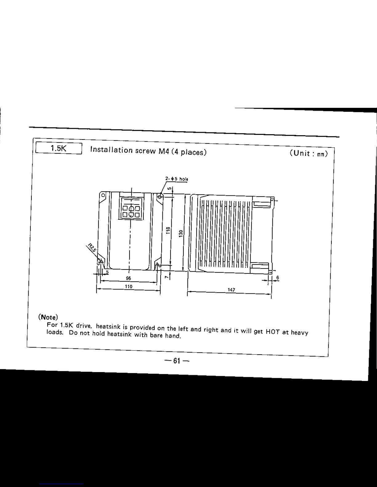
1.5K
Installation
screw
M4 (4
places)
2-<1>5
hor~
,
0
~
I, :
I
~I-
~
D@D
o
0
.
s
I
~
I
r==L
,
I-
-
1->
96
,I
I
-~
110
'"
(Unit:
mm)
(Note)
For
1.sK drive, heateink is provided on the left and right and
it
will get HOT
at
heavy
loads. Do not hold heatsink with bare hand.
-61-

• Low-acoustic noise series
FR-U12D-ND
- (UL)
I
0.1 to
OAK
!Installation
screw M4(3 places)
(Unit:
mm)
Keyhole
slot
dimensions
,
2_+s
lhOlt
I
n::::::::1i=n
'
~
Capacity
A
O.1K
86
O.2K
101
O.4K
121
-62-
-

10.75. 1.5K
I
Installation
screw
M4(4
places)
(Unit:
mm)
~
~
I, '
I~
r-
DgD
o
0
!
.
3
I
~
,
I
Iv
'-
96
110
Capacity A
O.75K 147
1.5K 155
(Note)
For
O.75K and 1.5K
drive.
heatsink is
standard
on the
left
and right and
it
will get HOT
at
heavy
loasd. Do
not
hold heatsink
with
bare
hand.
-63-
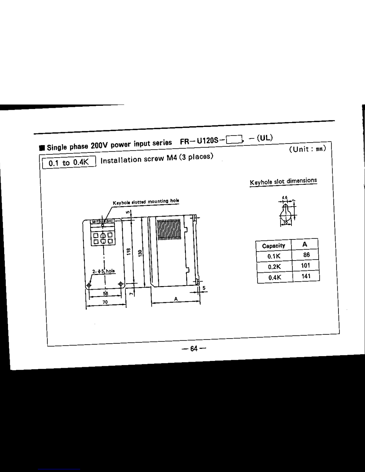
•
Sing10
phase
200V
powor input sorios
FR-
U120S-D
- (UL)
I
0.1
to
OAK
I
Installation
scrow M4 (3 placos)
(Unit:
rom)
Keyhole
slot
dimensions
Kayho\e slotted mounting hole
-64-
Capacity
A
O.1K
86
O.2K
101
0.4K
141
-----------
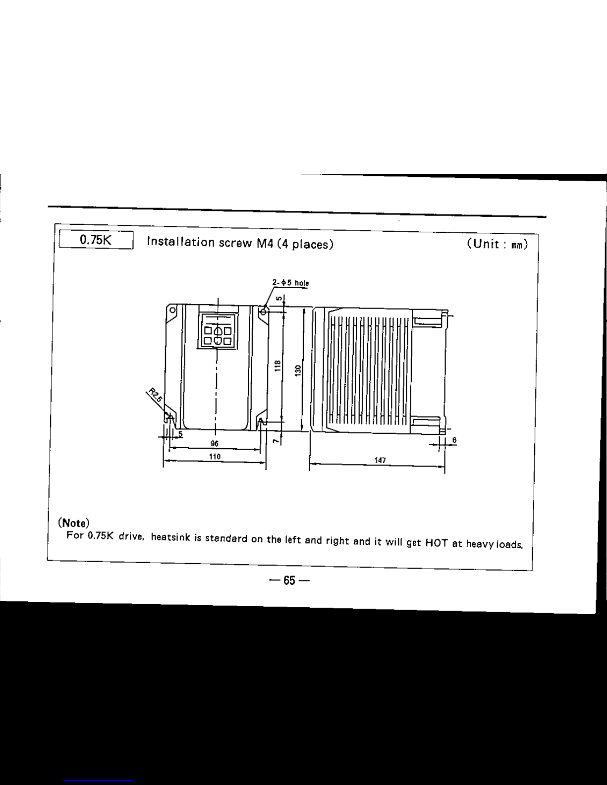
0.75K
Installation
screw M4 (4 places)
147
(Unit:
nm)
(Note)
For
a.75K
drive, heatsink is
standard
on the left and right and
it
will get HOT at heavy loads.
-65-

• Single phase
100V
power input series
FR-
ullow-D
-
CULl
I
0.1
to
OAK
I
Installation
screw
M4(3
places)
(Unit:
nm)
Keyhole
slot
dimensions
Ksyhole slotted mounting hOle
-66-
Capacity
A
O.1K
86
O.2K
121
O.4K
141

• Fully enclosed
type
series
FR-
U120-D-c
I
0.1
to
O.75K
I
Installation
screw
M4 (3
places)
(Unit:
mn)
Keyhole
slotted
"
mounting
hoII
"I
lin
~IS
2·,19
hole
...'.'l.1
Protective
cover
~
..
-
S IS
-~~~'f~~-~
J
.,
II
HEU
-iIOD
i'!
i'!
,
/t~:+~.f.~·~
I
J
2·
.p15
hole
r
~
III
J_...
I
.l,,-
I'
,
I ,
.~
se
"
---:r.'
70
A
Capacity
A
8
Keyhole slot dimensions
O.1K
101
38
~
O.2K
106
43
OAK
121 58
O.75K
141 78
*4.5
only for 0.1K.
-67-

1.5K
Installation
screw M4(4 places)
(Unit:
mm)
22.5 Prottetive cover
2-+5holll
f--E-J
r:":
;J
r;:.;2l
;~'-
F=
9'8
~
FUU~-I\OI
a
I
},n.
I
~
,
-
1jIl'
00
I
~
I
\1.
(Note) For 1.5K drive, haetsink is
standard,
so the
temprerature
will rise by approx. 30 degrees
depending on the usage conditions.
(Note) The 1.5K drive comes equipped
with
a fan.
-68-
-----------

-
•
Multi~functjon
low-acoustic noise, fully enclosed type
series
FR-
U120-
NCJ-C
10.1
to
OAK
I
Installation
screw
M4 (3
places)
(Unit:
nm)
~
,Iot!.d
s
~
ho~
.
5-1
t-t
2.
~
19holl 22.5
,;~~':,.:''-':'
'iJ;c
~
2_ 15
ho~
Keyhole
slot
dimensions
Capacity A 8
O.lK 106 43
O.2K 121 58
O.4K 141 78
0.75K
Installation
screw
M4 (4
places)
-69-

--------
1.5K
Installation
screw
M4
(4 places)
(Unit:
nm)
Prot~tiV,
~v,r
~.5
(Note)
For 0.75 and
15K
drive. heatsink is
standard,
so the temprereture will rise
by
approx. 30
degrees depending on the usage conditions.
(Note) The
UK
drive comesequipped
with
a fan.
-70-

9. SELECTION OF PERIPHERAL
DEVICES
• Selection of peripheral devices
(The
selection
will
differ
according
to the
inverter
power
supply
input
specifications. )
Power
Motor
Applicable inverter
No-fuse breaker
(NFB)
or
Magnetic contactor (Me)
Wining
(milO
input
output
model
Leakage breaker (NV)
(kW)
A
area
B
area
C
area
R,S,T
U,V,W
0.1
FR-Ul20-{Nlo.1K.(c).
·(UL)
NF30 model,
NV30
rnodel5A
S-K11
S-K1B
S-K20
2 2
0.2
FR·Ul20..(NJO.2K
-ic),
-W
L)
NF30 model.
NV30
model5A
S-K18
S·K20
S·K20
2
2
3-phase
0.4
FR-U1J)-(N)OAK-(cJ.
«uo
NF30 model,
NV30
model5A
S-K18 S-K21
S-K21
2
2
200V
0.75
fR-Ul2Q..!NJO.75K-(c).
-(UL)
NF30
model.
NV30 model10A
S-K18
S-K21
S-K21
2 2
1.5
FR-Ul211..(N)1.5K..(cJ.
-(UL)
NF30 model,
NV30
model15A
S·K21
S·K25
S-KSO
2 2
0.'
FR·Ul20S-(N)O.lK,
-(UL)
NF30 model,
NV30
model5A
S-K18
S-K20
S·K20
2
2
Single
0.2
FR-U12OS-(NJo.2K.
oWL) NF30model, NV30 model lOA S-K18 S-K21 S-K21
2
2
ph
ase
200V
0.4
FR-Ul20S-INlOAK,
.un.j
NF30 model, NV30 model 10A S·K21 S-K2S S-KSO
2
2
075
FR-Ul20S-V"-l)O.75K,
·(UL) NF30 model,NV30 model15A S-K2l
S·K2S S·KSO
2
2
0.'
FR·U
11OW-MO.1K
••( UL) BH-K model, NV30model lOA S-K18 S-K2l
S-K2l
2 2
Single
phase
0.2
FR-U110W-~'M.2K,
-CUll
BH-K model. NV30 model15A S·K21 S-K2S S-K2S
2
2
,OOV
FR-Ul10W·Mo.4K.
-CULl
BH·K model, NV30 model20A S·K21
S·K2S
S-K50
2 2
0.4
-71-

Power
Motor
Applicable inverter Power factor improve. low-acoustic noise
Fuse Rating
input
output
model ment AC reactor
outpUt
reeeter
Amp./Volt
(kW)
Class
0.1
FR·U12Q-(N)O.lK.(C~
·(UL) FR-BAL·OAK
(Note 4)
FR-BOL-O.4K
K50rH
3A/1fiJV
0.2
FR·U
12CKNlO.2K
.(c~
.(UL)
FR-BAL·O.4K
(Note4)
FR~BOL-O.4K
K50rH
5A/'1SOV
3-phase
0.4
FR-Ul2O-(NJO.4K.(C~
·(UL)
FR·BAL·O.4K
FR·BOL-OAK
K50rH
8A/250V
2JiOV
0.75
FR·Ul~O.75K.(c).·(UL)
FR-BAL-O.15K FR·BOl·O.15K
K50rH
15A/250V
1.5
FR·Ut~O·.(N)1.5K.(c~
·(UL) FR-BAL·1.5K FR·BOL·l.5K
K50rH
'JSA/ZiOV
0.1 FR·U
120S-(N)O.1
K.• (UL) FR-BAl-O.4K
(Nctea)
FR· BOl·O.4K
K50rH
5A/'I5OV
Single
0.2 FR·U
126S-(N)O.2K
••(UL) FR-BAl-O.4K
(Note4)
FR-BOl·O.4K
K50rH
BA/'I5OV
phase
FR.Ul20S.(N)O.4K.·(
UL) FR-BAl-O.15K
(Note4)
15A/'I5OV
2JiOV
0.4
FR·BOL·O.4K
K50rH
0.75
FR·UU~OS·(N)O.15K,
.(UL)
FR-BAl-l.5K
(Note4)
FR-BOl·O.15K
K50rH
'15A/25fJV
0.1
FR·UllOW411o.1K.·(
UL) FR-BAl-O.4K
(Note 4)
FR·BOL·O.4K
K50rH
8A/250V
Single
ph
ase
0.2
FR-Ul10W.(N}o.2K,
-(UL) FR-BAL-O.75K (Note4)
FR-BOL·O.4K
K50r
H
15A/250V
100V
FR·UllOW4110.4K,
.(UL) FR-BAL-1.5K
(Note 4)
FR·BOL·O.4K
25A/'I5OV
0.4
K50rH
-72-
-----------

A
B
10
c
5~,t::===~===~,-
__
(Note)
The figure shown is based upon wire
sizes recommended in the above table.
Power
source
capacity
(I::VA)
(Note)
1. The wiring sizes
are
shown for a 20m length.
2. When installing an
Me
on the inverter
power
supply, select the model according to
power
supply
capacity
and wiring distance as
shown
on the right.
The
A,
B, C
areas
in the figure correspond
to
those
in the above table. S-K10 is selected
when using a
power
factor
improvement
reactor
FR-SAl
on the 0.4 to 1.5K models.
3. Use a
4>
0.4 to
4'
1.0 solid
wire
or 0.3 to
0.751'11111
stranded
wire
for
the control lead.
4. The
power
factor
may
drop
slightly below 0.9.
-73-

• An excessive peak
current
will flow to
the
power
supply
input
circuit when
the inverter is directly connected to a
large
capacity
power
supply
trans-
former
(500kVA or more,
wiring
10m
or less), and the inverter
may
be
damaged.
Always
install
the
optional
power
factor
improvement
reactor
FR-BAL in
this
case.
(Use
the
O.4kW
FR-SAL
for 0.1K
and
0.2K.l
Power
source
1000
capacity
(WA)
10
Wiring
length (m)
• The
wiring
length between the inverter and
motor
must
be less
than
100m.
The
control
line
must
be 30m or less and
must
be
separated
from
the
main
power
wire. Use a twisted
pair
wire
for external frequency setting
signal
input.
Inverter
R U
5 V
T W
• Connect as
shown
below when installing.
a-phase
NFe
FR.eAL
_;£
R.
-
x
Power
s:
'y
suPplY:
T'
I
Z
-74-
Single phase
NfB
FR-BAL
Inverter
.'1',R-
-x
PowerAsl
'y
R U
supply-
S V
T~Z
W

Revision
Publication
Instruction
Details of revision
date
manual
No.
AUG.
1993
IB(NA)·66425-A
First
edition
IB(NA)066425- B
Addition:
Single phase power supply version
SEPT.
1993
Low-acoustic
noise
version
Fully
closed
Version
JAN.
1994
IB(NA)066425-C
Addition
:
Page
2.9.18
NOV. 1994
IB(NAl·66425-D
Partly
revised
(A5
size-.A6
size)
MAR.
1996
IB(NA)066425- E
Addition:
Page
20.46.47.48.51
JULY.
1995
IB(NA)066425-F
Addition:
Stop key function. Pr.75
),.MITSUBISHI ELECTRIC CORPORATION
HEAO OFFICI2MITSUBISHI OENKI BLDG. MARUNOUCHI TOKYO 100
TELEX:J2~S32
CABLE MELCO TOKYO
TYPE
FR·U120 EIBUN TORISETU
CODE
.1A2-G32
IB(NA)66425·F(OSOO)ROO Printed in
J"P""
SlltGlficatiO","... ,ubjoct to
</I""g.
without
"otu
 Loading...