

Mitsubishi FREQROL-SFJ Maintance Manual

r‘
LiC SPINDLE DRl.i/E
. . . .
t .,.
. .
-SFJ L
*’
P
MAINTENANCE -MANUAL
:
BNP-A282 l-02-A-E
ADVANCED AND EVER ADVANCING
n/lmJBlsHl
ELEcTmc

-CO.NTENTS-
1.
GENERAL
1.1
Introduction
1.2
Safety during
maitenance
and troubleshooting
1.3
Storage
2. WIRING
2.1
External wiring
2.2
Parts arrangement
3. ADJUSTMENT
3.i
Preliminary check
3.2
Power feeding
3.3 FR-SFJ status display and parameter settings
. . . . .
1
. . . . .
1
. . . . .
1
. . . . .
2
. . . . .
3
. . . . .
3
. . . . .
10
. . . . .
12
. . . . .
12
. . . . .
13
. . . . .
15
3.3.1 (A) Status display and parameter setting
for ROM version A
. . . . .
17
3.3.2
(B)
Status display and parameter setting
for ROM versions after BO
3.4 Spindle control monitor on NC CRT dispaly
. . . .
when FR-SFJ is connected to M300 CNC
through bus line
3.5 Spindle control monitor on NC CRT display
. . . .
when FR-SFJ is not connected to M300
CNC through bus line
3.6 Test operation
3.7 Adjustment of motor speed
3.8 Adjustment of oriented spindle stop function
3.9 Parameter list
4. CARD SETTINGS AND CHECK TERMINALS
4.1
Card SFJ-CA1
4.2
Card SF-ORJ
4.3
Card SF-TLJ
4.4 Card SF-DAJ
5. ADDITION AND REPLACEMENT OF COMPONENT
5.1 Addition of option card (SF-ORJ, SF-DAJ and
SF-TLJ)
5.2 Replacement of card
5.3 Replacement of ROM
5.4 Replacement of diode moduie and transistor
module
. . . . .
2C
. . . . .
26
. . . . .
29
. . . . .
32
. . . . .
32
. . . . .
34
. . . . .
42
. . . . .
50
. . . . .
50
. . . . .
55
. . . . .
56
. . . . .
57
. . . . .
58
. . . . .
58
. . . . .
59
. . . . .
60
. . . . .
61
5.5 Disassembly and assembly of SJ-J type AC spindle motor
. . . . .
63
-
1/2-
6.
INSTALLATICN OF ORIENTED SPINDLE STOP POSITION
DETECTOR
6.1 Magnesensor l-point oriented spindle stop
7.
DISCHARGE RESISTOR UNIT
a.
TROUBLESHOOTING
a.1
General information
,a.2
First step of troubleshooting
a.3
Second step of troubleshooting
8.4 Alarm and warning table
a.5
"Alarm/warning"
display by LED readout
9. PERIODIC INSPECTION
9.1
Inspection of control equipment
9.2
Inspection of motor
9.3
Inspection of discharge resistor unit
10. PARTS LIST
. . . . .
72
. . . . .
72
. . . . .
a2
. . . . .
a3
. . . . .
a3
. . . . .
a4
. . . . .
86
. . . . .
a9
. . . . .
94
. . . .
115
. . . .
115
. . . .
116
. . . .
ii8
. . . .
119
-2/2-

$1.
GENERAL
1.1
Introduction
AC spindle drive unit, FR-SFJ series, is the inverter use,?
,-
to control a machine tool spindle drive AC motor.
It is capable of
contro.lling
widely ranged motor speeds ac-
curately and quietly.
Discharge resistors are
connectec t-:
the drive unit to disperse regenerative energy for regenerative braking of motor.
This manual mainly describes periodic maintenance and trou-
bleshooting which are very important to assure successful
use of your AC spindle
drive.unit.
1.2
Safety during
maitenance
and troubleshooting
The maintenance and troubleshooting should be done with the
following safety consideration:
o The control system should be maintained and remedied by
qualified electrician.
o When a person who maintains or remedy the control system
must touch a part of control system under live condition,
he should take off finger ring, wristwatch, necktie pin,
and other metallic goods before starting the work.
o Electric shock may cause fatal accident.
When a circuit at high voltage must be checked, due care
should be taken to select appropriate test/inspection
equipment, tools, etc.
and to use them safetly (no matter
whether or not the circuit is grounded).
When a test equipment is applied to a part, component, or
circuit of the unit,
operator should pay attention not to
touch a grounded part.
In general,
test equipment should not be grounded.
During test or measurement, it is likely that high voltage
is present across the test equipment and the ground.
When motor is run during adjustment or remedy, due care
should be taken in this respect.
o Person who carries out maintenance or remedy of rotative
machinery should not wear loosely (otherwise loose wear
-
l-

might be involved into the running machine.
o DO NOT TURN OFF THE POWER IMMEDIATELY AFTER OPERATION IS
TERMINATED.
THE UNIT SHOULD BE HELD TURNED ON FOR AT
LEAST 10 MIN.
FOR COOLING THE DISCHARGE RESISTOR UNIT
(BY COOLING FAN), AFTER THE OPERATION.
IF THE DRIVE UNIT IS TURNED OFF IMMEDIATELY AFTER THE
TERMINATION OF OPERATION, THE RESISTOR UNIT COOLING FAN
STOPS AND RESIDUAL HEAT, OF RESISTOR UNIT MIGHT CAUSE BURN-
ING OR DAMAGE TO OTHER COMPONENTS OF DRIVE UNIT.
o Do not touch the drive unit immediately after the opera-
tion is terminated (maintenance or remedy should be started in about 5 min.
after the operation is terminated).
1.3
Storage
When your AC spindle drive unit is not used, store it in
clean and dry environment.
Note that humidity and dust entering into the control unit
may adversely affect insulation resistance of the drive unit.
When your, AC spindle drive unit is left out of operation for
any length of time,
the same cautions should be taken.
It is recommended,
if the storage is humid, to use a heater
to keep the environment dry.
.
-
2
-
f-
c
92.
WIRING
2.1
External wiring
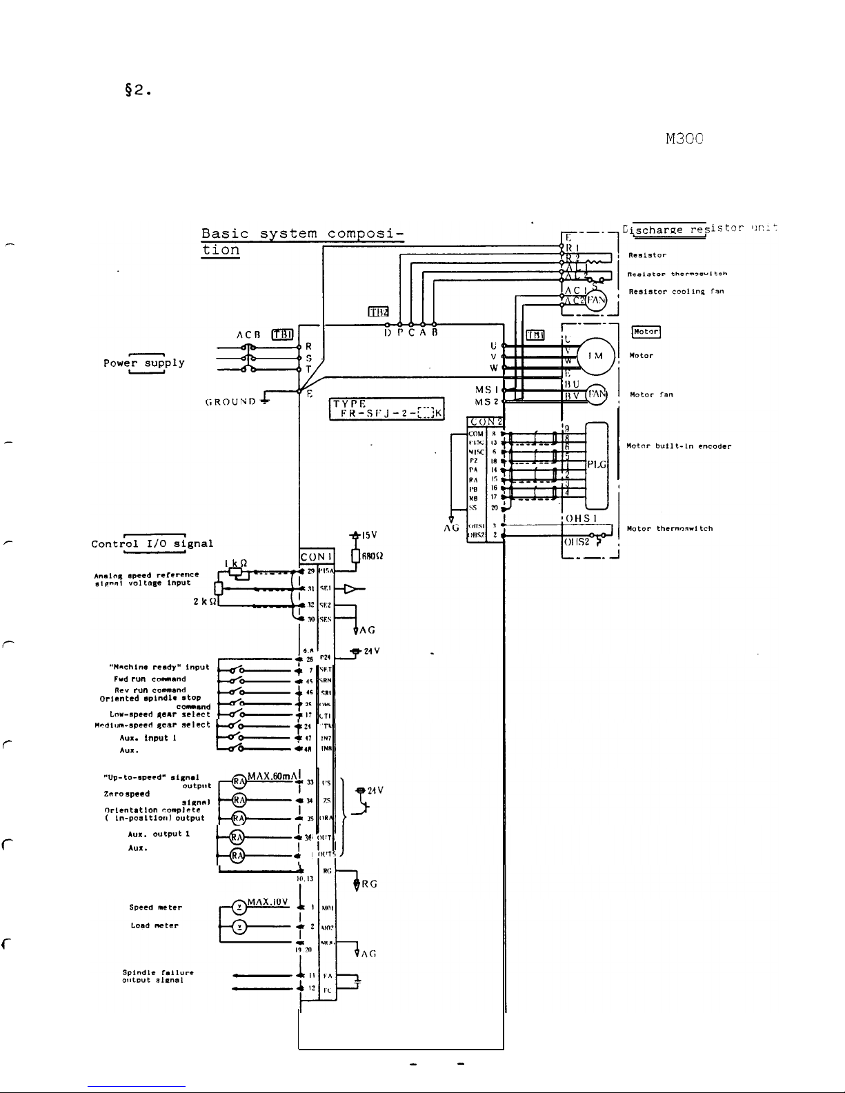
2.1.1 Control system.where FR-SFJ is not connected
through bus line
a. Analog speed reference
signal
“““chins rc*dy” Input
FWd
r””
command
R.3” run
command
orlsnttd
eplndl*
atoP
commmd
I.“*-spewi qsllr
select
“rdlum-specrl
genr select
AUI .
Input I
E
Yir:
AUX.
input 2
A
C4I
I
“Up-to-speed”
st.m.1
O”tpUt
Zero
speed
output
5111”“1
“rlcntation complete
(
In-po~ltIorl)
output
-
AUX.
output
1
I
.
36
*“I.
output 2
Is=_
R
I
e
21
to
M300
Nischarne r-es
-
3
-
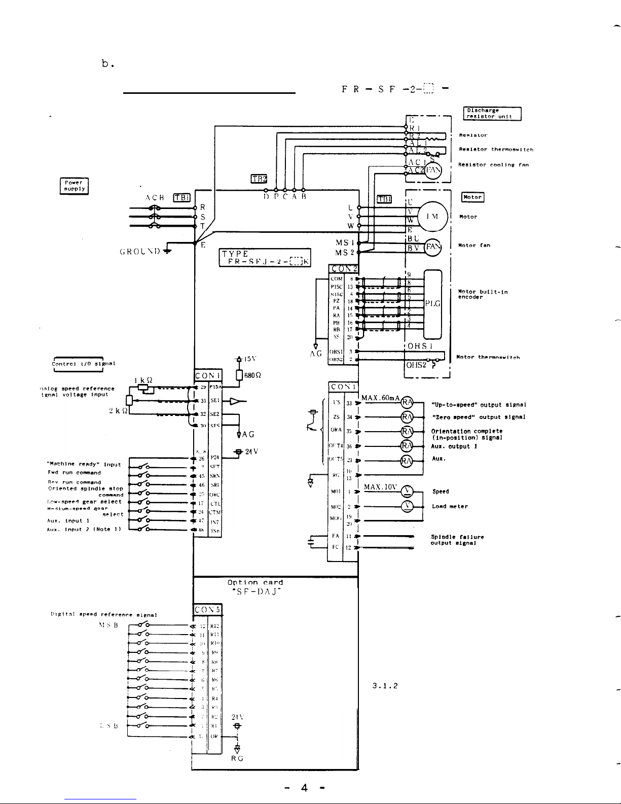
b.
Digital speed reference signal (option card SF-DAJ is used)
Basic system composition
F R - S F
J - 2
-;;I;
K - D
“VP-to-epee.9, OUrpUt
aima,
“Zero speed”
output
signal
tJr,entstion ccmplett
(in-porrItIon~ signal
A”X. O”Ip”t
I
A”X.
output 2
speed
meter
Lord rnCtCr
‘SF-DAJ”
Note 1:
This input port is used for speed
reference signal selection
between “analog” and “digital”.
For details,
refer to paragraph
3.1.2
“Auxiliary input signals”
in the Standard Specifications.
- 4 -
f---
c
c
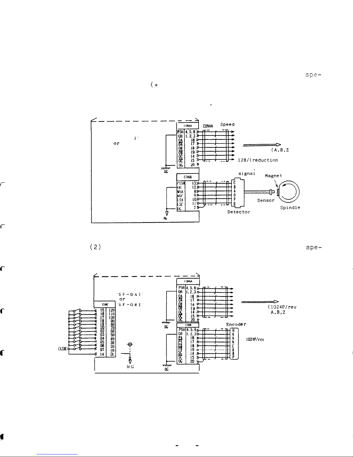
c. Control system equipped with oriented spindle stop func-
tion
A circuit
illustrated below is added to the basic system.
(1) Magnesensor type oriented spindle stop (1 point)
see-
cification (+ motor
speed feedback signal output)
(For spindle speed display/sync. feed
signal)
.
f
_---
---
--
Option card
I
‘SF-DA
1’
OI-
'SF-OHJ'
.!.
_^
Maqnesensor
display/sync. feed signal
_____h
To NC
(A.B,Z
phases)
Pulse nu Number of pulses is
128/(reduction ratio).
detect
Magnesensor
(2)
Encoder type oriented spindle stop (4096
cification,
equipped with index function
+_----_--_T_~
points)
spe-
Option card
'SF-D41'
Oriented stop
position command
Speed display/sync. feed signal
e
To NC
(1024P/rev
A.B.2
phases)
er
detect signal
-
5
-

(3)
Z-phase controlled motor built-in encoder type ori-
ented spindle stop (4096 points) specification, equipped with index function
Motor detector signal
_______----------
Option card
'iented
spindle
'5
F-DA
1’
top
position
ed display/sync. feed signal
Tmmand
SF-OKJ'
-----hTo
NC
(128P/rev
A,B,Z
phases)
-.
-
6
-
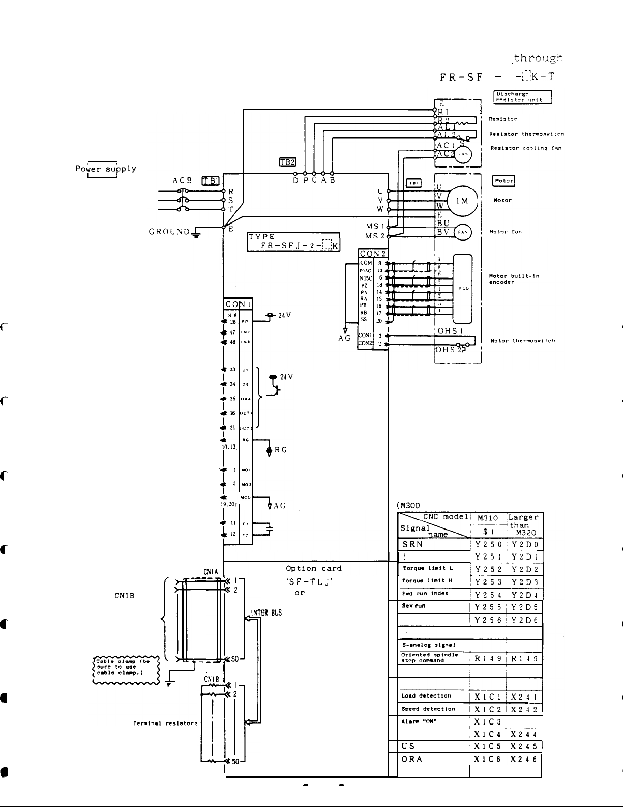
2.1.2 Control system where FR-SFJ is connected to M300
,through
bus line (option card SF-TLJ is used)
FR-SF
J - 2
$K-T
a. Basic system composition
I
QR
I
I
Poker supply
I
J
Connection is not
required for CON1
signal in usual
operation.
c
c
c
I/O signal assignment
CM300
series interface)
c
SRI
jY251~Y2DI
CNI
____
A
‘<
1
‘<
2
,I
IVEIl
I
so
CNll7 ,
‘<2
!
le
7
:
'SF-TL.J'
Ot-
'SF-RSJ'
To
CNlB
of
final axis
MR-S servo
amplifier
Rev
run Index
/Y255;Y2D5
ORC
lY256!Y2D6
BLS
c
*,.rm
“on”
jXIC3
X243
ZS
IXIC4/X244
us
lxlc5ix2451
ORA
/XlC61X246
J
-
7
-
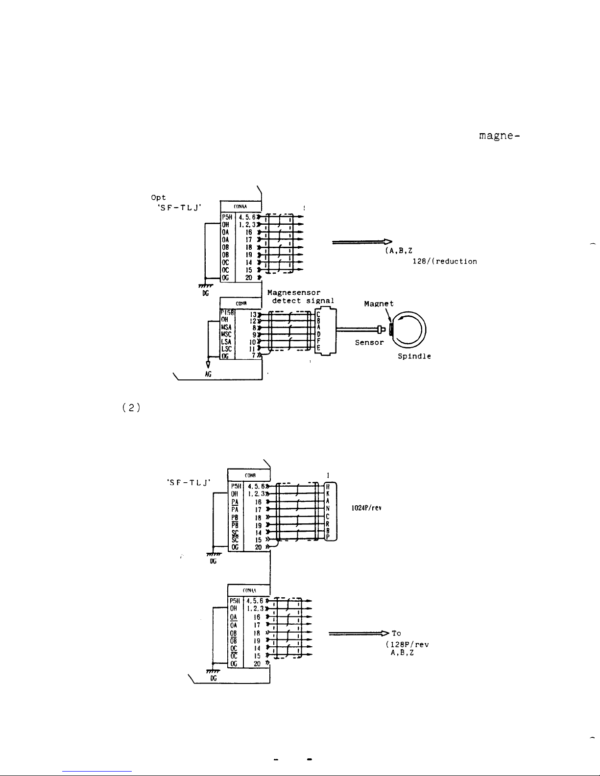
b.
Control system equipped with oriented spindle stop func-
tion
A circuit illustrated below is added to the basic system.
(1) Motor built-in encoder high-speed sync. TAP and
magne-
sensor type oriented spindle stop (1 point) specification
Opt
'S
ion card
Speed display/sync. feed signal
-
To NC
(A.El.2
phases)
Number of pulses is
128/(reduction
ratio).
Magnet
Detector
Magnesensor
(2)
Encoder high-speed
sync.
TAP and multi-point (4096
points) oriented spindle stop specification, equipped
with 'index function
Option card
Encoder detect signal
1024P/rev
Speed display/sync. feed signal
-To
NC
(128P/rev
A,B.Z
phases)
-
8
-
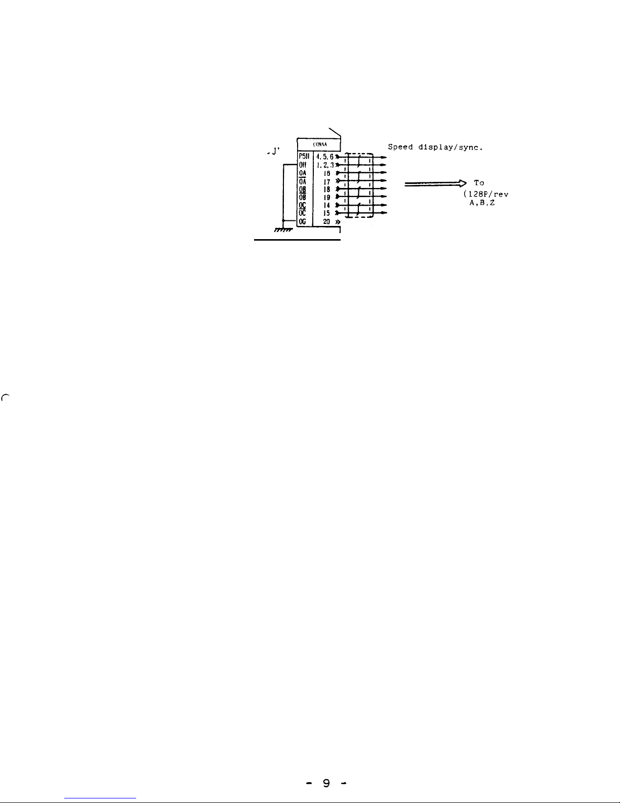
(3) Z-phase controlled motor built-in encoder high-speed
sync.
TAP and multi-point oriented spindle stop spe-
cification,
equipped with index function
Option
‘SF-71
card
A
-
To
NC
(128P
‘/rev
A,B,
,Z
phases)
feed signal
- 9 -
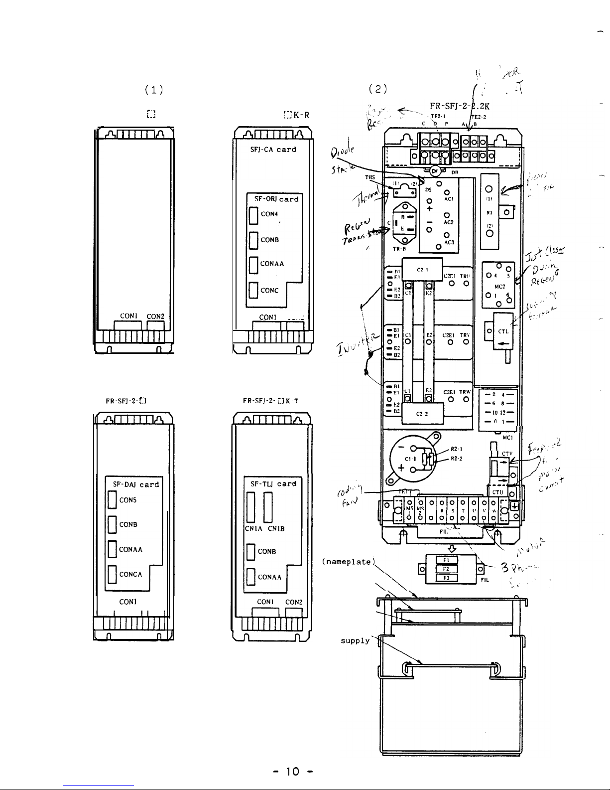
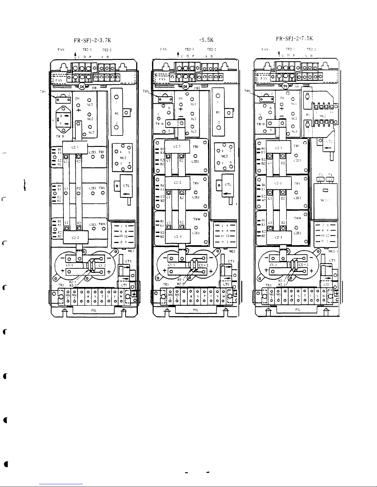
2.2 Parts arrangement
(1)
SFJ-CA card and option
card
1
‘,’
,,
,&
(2)
Main board
L
f I’
\ -1
FR-SFJ-2-
:::
K
fit 1 1 II1lA
SFI-CA card
FR-SFJ-2-
:::K-R
SFJ-CA card
r
Option
CON1 CON2
In
n,
r
OP
II!
b
RI
0
6
04 ?
Et
MC2
01
6
O0
0 Cfl.
%f
-2
I-
-6 .3-
1
-10 12-
-” ,-
CON1
CON2
n
n
FR-SFJ-2- Ll K-D
FR-SFJ-2-
i:IK-T
SFJ-CA card SFJ-CA card
option
0
@
w-1
Cl
I
R2.2
t
0
CTV
IQ?
0
Option
Front
panel
(namer
Ilate)
Option card
Card SFJ-CA
z
CON1
CON2
nn
r
IP-PM power
-
10
-
c
c
c
c
FR-SFJ-Z-3.7K
0
“\
0
:
3‘ !
0
KL’
0
1
l-l-
.c?
J
I
I
’
-L 4-
-Ii
n-
-111
,z-
-n ,-
FR-SFJ- -5.5K
-
11
-

$3.
ADJUSTMENT
3.1
Preliminary check
Before turning on FR-SFJ, perform the following check:
(1) Is the external wiring in conformity with the relevant
wiring diagram?
(2) Are the motor and the drive unit grounded properly?
(3) Are all shielding wires terminated properly?
o Is each shield
armour
connected to the corresponding
terminal'?
o Is each shield
armour
not looped?
(4)
Is any component or part not loose?
(5) Is any foreign matter is not involved in the drive unit?
(6) Is there any damage or defect on
each,P.C.
board?
(7) Do ROM No.
and jumper pin settings meet the order sheet?
-
12
-
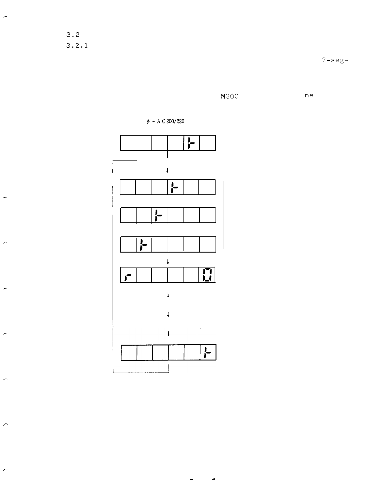
3.2
Power feeding
3.2.1
Turning on the power
Immediately after the FR-SFJ is turned on, see the
?-seg-
.ment LED readout at the center of front panel to check
conditions:
(1) For FR-SFJ connected to
M300
through bus 1
.ne
3
4-AC200/220
ON
1
I
1
+ NC power is turned on.
I
1
1
1
Normal operation
1
NC power is turned off.
Wait for turning on NC power
Initial data communication with NC (momentary
display)
Initial data communication
complete
Wait for "ready ON".
Wait for turning on NC
Alarm code is
displayed in
case of failure.
-
13
-
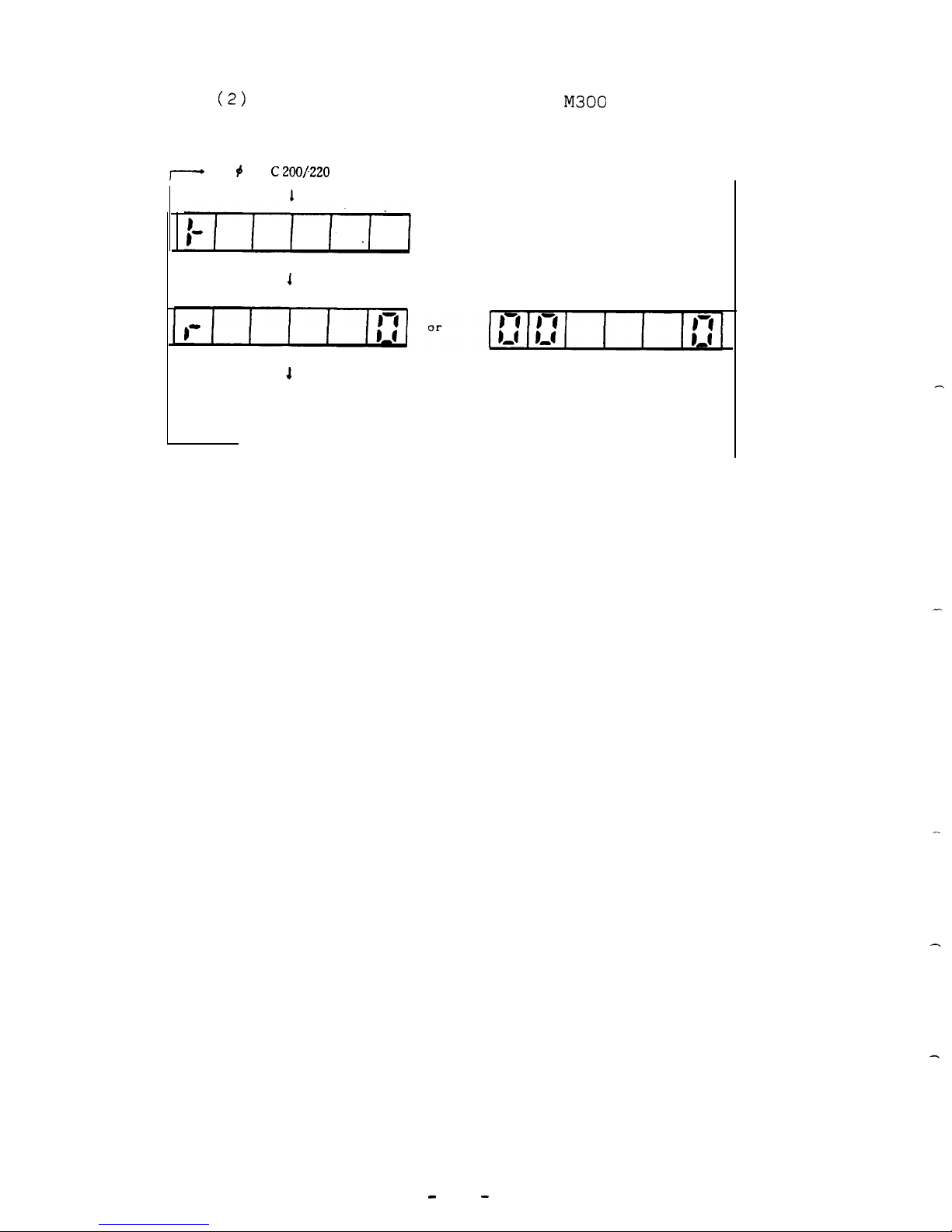
(2)
For FR-SFJ not connected to
M300
I_
3 # -A
C200~220
0 N
1
1
Normal operation
1
Power is turned off.
Alarm code is
displayed in
case of failure.
-
14
-
3.3 FR-SFJ status display and parameter settings
c
c
Operation status is displayed by the 7-segment LED readout
on card SFJ-CA1 and parameters can be set by DIP switches.
Status display and parameter settings depend on ROM version
of card SFJ-CA1 card.
For ROM version A@ . . . . .
(A) 3. 3. 1
For ROM version BO and thereafter . . . .
(B)
3. 3. 1
When FR-SFJ is connected to M300 CNC through bus line, sta-
tus can be displayed and parameter can be set on the NC CRT.
(For details,
refer to 3.5.)
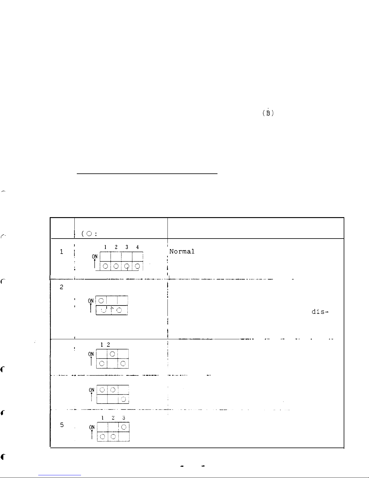
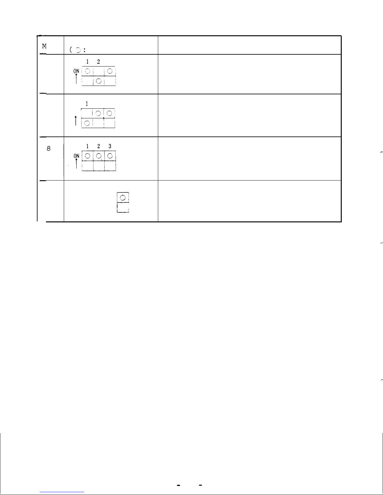
DIP switch settings and functions
Since DIP switch settings must be changed only when test operation is required, they should not be changed during normal
operation.
Mode
DIP switch setting
Function
/ (0:
Set position)
1
I
1 j
i
Normal
operation
;
g@$
!
I ,
I
I_i_
_--_._ -.._- _-._._...
.__!_-_-_-_- ._-_.._ -_ __.__-__ ___. ___ _. __
_
2
i
1
2 3
[
Spindle parameters displayed by NC
/
CRT are ignored.
,
ON !o/
I
I
;
I
,-
j ‘A j c ]
When FR-SFJ is connected to M300 CNC,
the spindle parameters set and
dis-
I
I
played on the CNC side are ignored
!
and the parameters set on the FR-SFJ
side are used.
I
!
-.--.
.--__
_.. ._ _. .
._
3
!
1 2
3
I
Setting prohibited (for manufacturer's
1
test operation)
_._._
4
__ __-
-~_--.-.
-.-
._-_--_ .._
&_
_....
-.
1
2 3
Setting prohibited (for manufacturer's
c
-
15
-
M
-
-
-
-
ode
DIP switch setting
(
3:
Set position)
Function
1
2
3
6
1
2 3
7
I
1
ON; ,
i3lC!
I’
v!
I’JI
’
j j
Initialization of parameters
The standard values (manufacturer's)
are set for all parameters.
User should not use this setting.
9
4
Meter test mode
c
931
Speed meter/load meter output
I
;
(for ROM versions after BO)
-
16
-
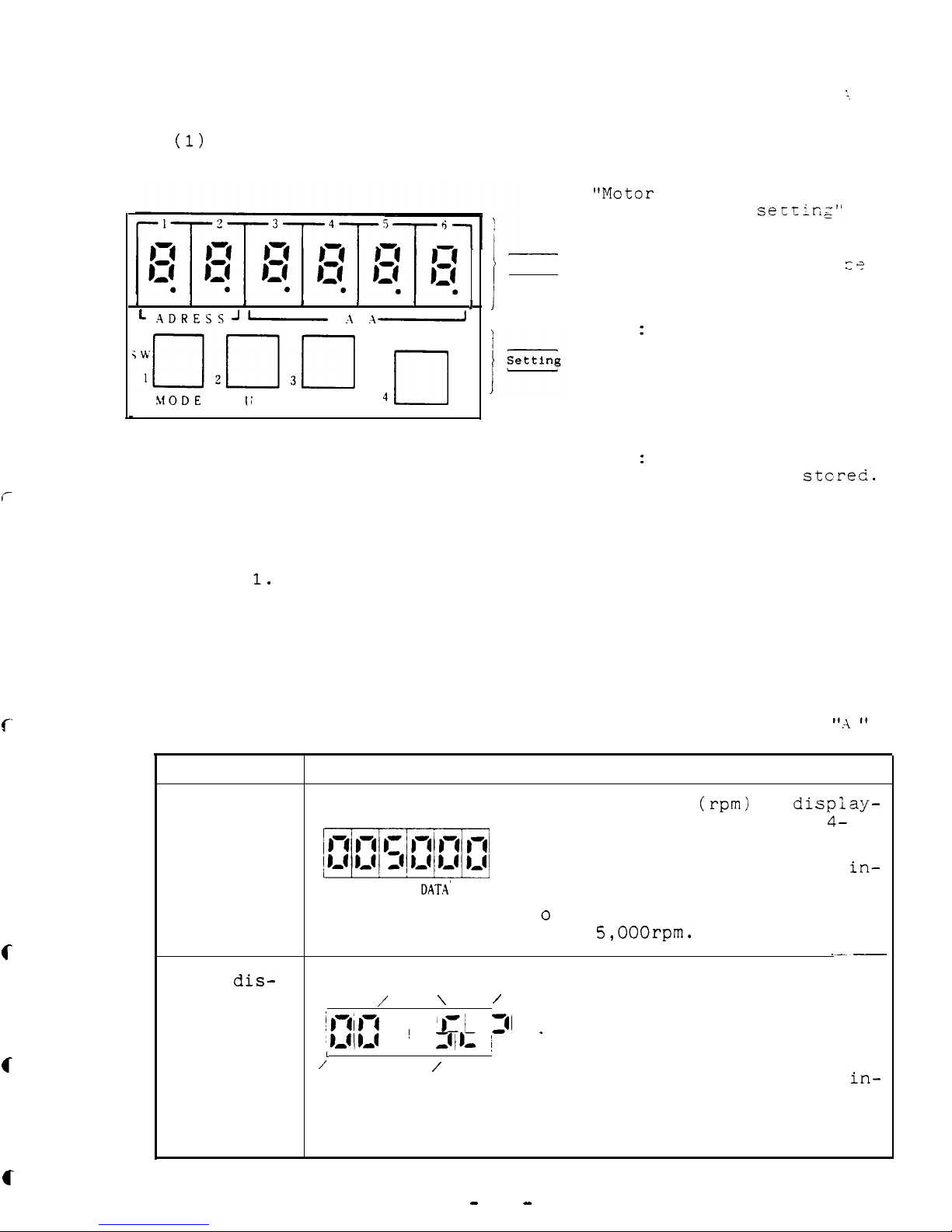
3.3.1 (A)
Status display and parameter setting for ROM version
1
(1)
Readout and switches
I
I
I
I I
I
I
L
ADRESSJ
-
D A T
.A-
clr13~
4n
!dODE
Ii
P
DOWN
SET
"Motor
speed", "alar::"
and
"parameter
seLting"
are displayed.
I-
1
Display
MODE:
Display mode can
c?
selected between
ADDRESS and DATA.
UP
:
Value displayed in
ADDRESS and DATA
can be incremented.
DOWN: Value displayed in
ADDRESS and DATA
can be decremented.
SET
:
Data set for para-
meter can be
stcred.
1) The display modes include "motor speed" display, "alarm"
display, and
"parameter setting",
as described in Table
2) After turning on the power, "motor speed" is displayed
unless alarm occurs.
3) In case of alarm,
alarm code is displayed.
c
c
c
Table 1
Display modes and information for ROM version
I'.\ I'
Display mode
Display example and information
Motor speed
o Motor speed
(rpm)
is
dispiay-
display
mi
ed in DATA section with
4-
digit numerals.
ADD
DAT.A'
o Display in ADD section is
in-
significant.
o In this example, motor speed
is
5,OOOrpm.
Alarm
dis-
o In case of alarm, alarm No.
play
\
/
\
/
and alarm code are displayed
'RI;-!
~
‘,:I
31
.
in DATA section with 2-digit
J/L
~
numerals (for details, refer
1,-
L
to APPENDIX 1).
/
\
/
\
o Display in ADD section is
in-
They flicker.
significant.
o This example shows occurrence
of
"excess error".
-
17
-
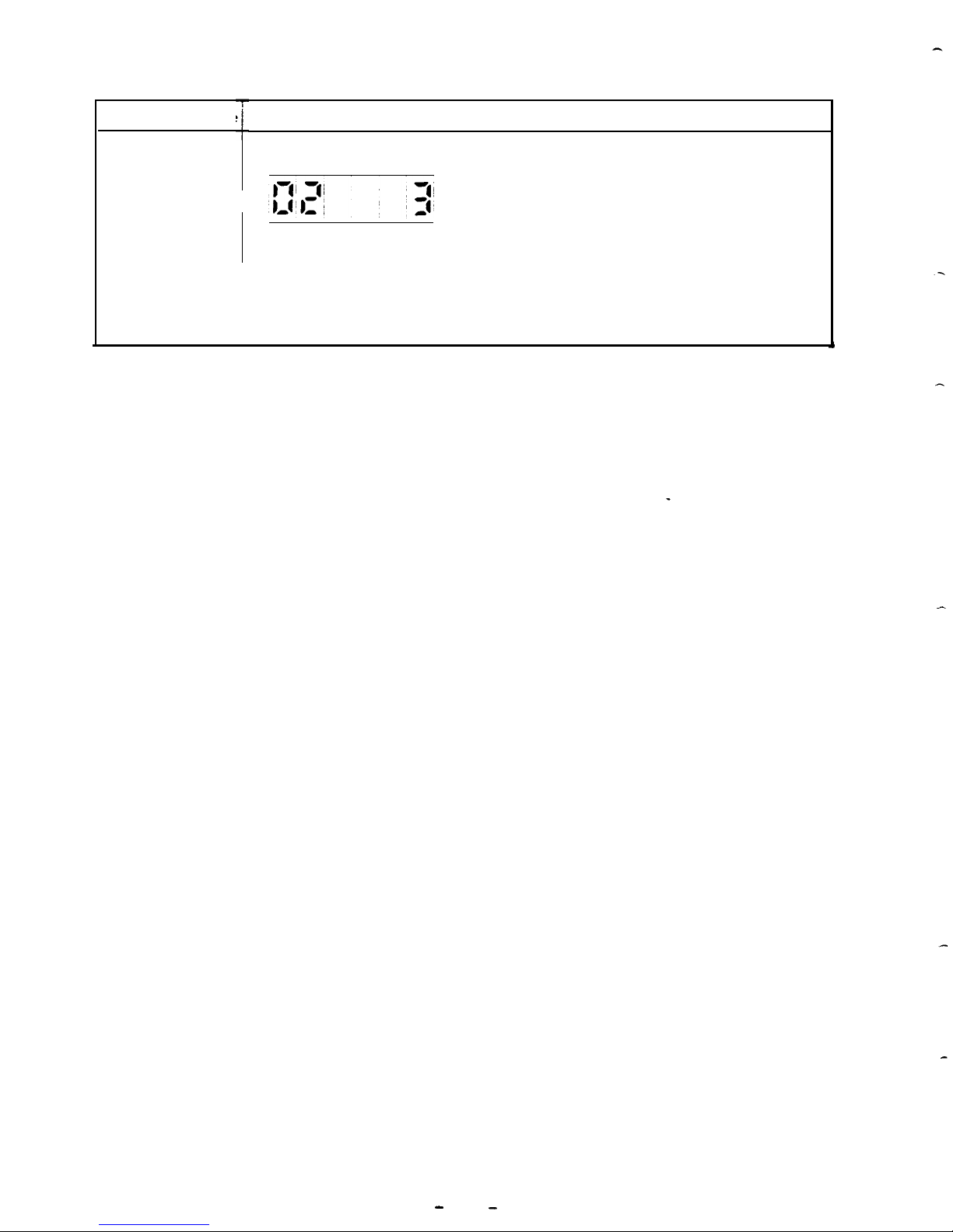
Display mode
Parameter
display
Display example and information
0
0
0
Parameter address (parameter
No.) and data value are dis-
played in ADD and DATA re-
spectively.
For methods of setting para-
meter,
and checking set para-
meter,
refer to the next page.
For details of each parameter,
refer to 3.9.
1
-
18
-

f
(2) Parameter setting
Set parameters with READY signal (SET) turned off.
o Motor speed is displayed
(Fig.
1) when alarm does
not occur.
ADD
DATA
Fig.
1 Motor speed
display
0 Each time @ switch is pressed, ADDRESS and
DATA alternate.
'0
Desired address can be selected in ADD section
Selecting the
by pressing
morH
switch.
Data at the
selected
address is displayed in DATA section.
(G&p->
Note:
If display in ADD
section does not
change,
but DATA
f;;=$$;~~:,
press w switch
t;
Fig. 2
I
1
*
changemode
from
DATA to ADDRESS.
(Data at address
"02 II
is displayed
Ex.:
In example shown
in **.)
in Fig. 1, ADD dis-
play changes to
S
I
when
cl
UP
switch is
pressed, and to
SZ
when the switch is
pressed again (Fig. 2).
o Display in
DATA section can be incremented
or decremented by pressing
@*or @
switch.
to set desired value for DA
o E;tB;zzsing a switch, the set data can be
.
o After the desired data has been set, press
mlfll
E
switch on card SFJ-CA1 or turn off and
en on the power to reset FR-SFJ.
Now data setting (parameter setting) has been
completed.
f
-
19
-
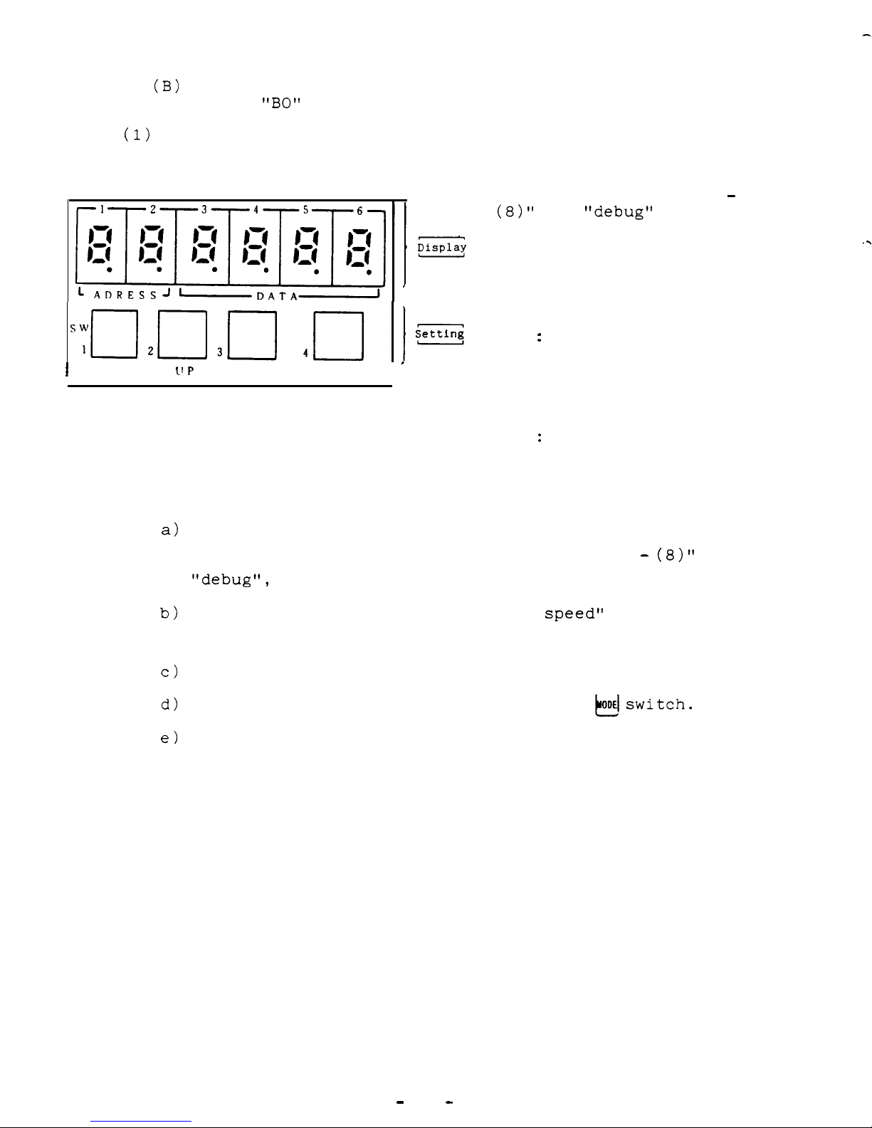
3.3.1
(B)
Status display and parameter setting for ROM versions
after
"BO"
(1)
Readout and switches
I
MODE
If P
DOWN
SET
I
’
Located on card SFJ-CA1
a)
b)
c)
d)
e)
"Operation status",
"dia-
gnosis",
"error alarm",
"parameter setting (1)
-
(8)"
and
"debug"
can be
displayed.
Function of each switch is
as follows:
MODE:
UP
:
DOWN:
SET
:
Display mode can be
changed.
Value displayed in
ADDRESS and DATA can
be incremented.
Value displayed in
ADDRESS and DATA can
be decremented.
Data set for parameter is stored when
this switch is pressed.
12 display modes, namely, "operation status", "diagnosis",
"error alarm",
"parameter setting (1) -
(8)"
and
"debug",
are selectable.
After turning on the power, "motor
speed"
is displayed
automatically unless alarm occurs.
In case of alarm, alarm code is displayed.
Display mode can be changed by pressing
kdswitch.
For display mode sequence and display content, refer
to the chart on the next page.
. .
-
20
-
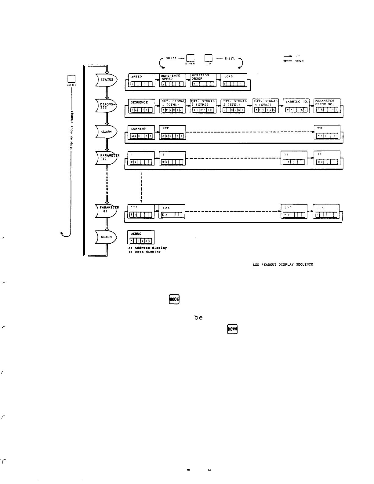
(2) Readout display mode sequence
1
L
2
, , ]
t_______-________________~~~_~~~
o Display mode can be selected in the sequence shown above
by pressing
EEI
D
switch.
o Display content can be changed within the same'display
mode by pressing UP or o
0
El
switch.
f
-
21
-
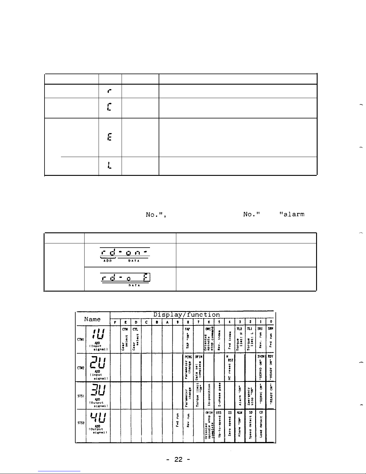
(3) Operation status display mode
In operation status display mode,
codes listed below are
displayed.
Item
Code
Unit
Description
Motor speed
I-
rpm
Motor speed is displayed.
Reference
-
I_
rpm
Commanded reference motor speed is
speed
displayed.
Position
Pulses
Number of 'remaining pulses (delay
control
pulses) on deviation counter is
droop
%
displayed.
For pulses (minus) in reverse rota-
tion,
decimal point lights.
-Load
I_
%
Load condition is displayed (100%
for 30min.
rated output).
(4) Diagnosis display mode
In diagnosis display mode, "control sequence", "external
signal",
"warning
NO.",
"parameter error
No."
and
"alarm
No."
can be displayed.
Item
Display
Description
Control
,- c
_I -
0 1-l -
Indicates that the controller
sequence
-
ID" DATA
is ready for operation.
I- ,=: -
I:1
I-
Indicates that the'controller
ADD
nlfl
is not ready for operation.
(5) External I/O signals . . . . .
I/O signal can be monitored.
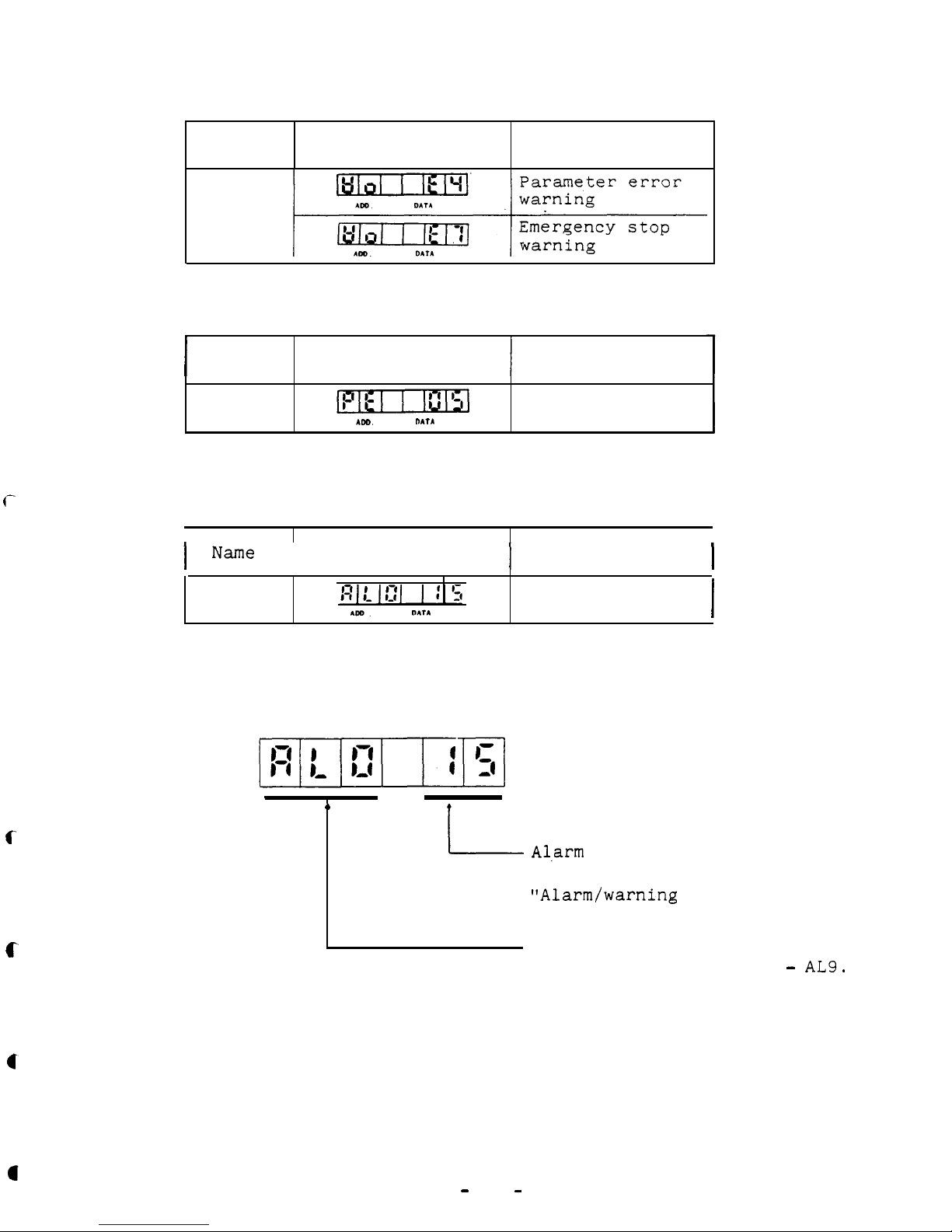
Warning No.
c
Name
Display
Description
Warning
No.
e
'Parameter error No.
I
Name
Display
Description
Parameter
error No.
Parameter error
IDD.
MT*
No. is displayed.
(5) Alarm display mode
Alarm No.
1
Name
i
Display
I
Description
I
Alarm No.
Alarm No. is
displayed.
I
c
.
I-
c
Alarm display
Al.arm
No.
is displayed.
For details,
refer to a.4
t'Alarm/warning
table".
Concurrent alarms are display-
ed in the order of AL0 -
AL9.
-
23
-
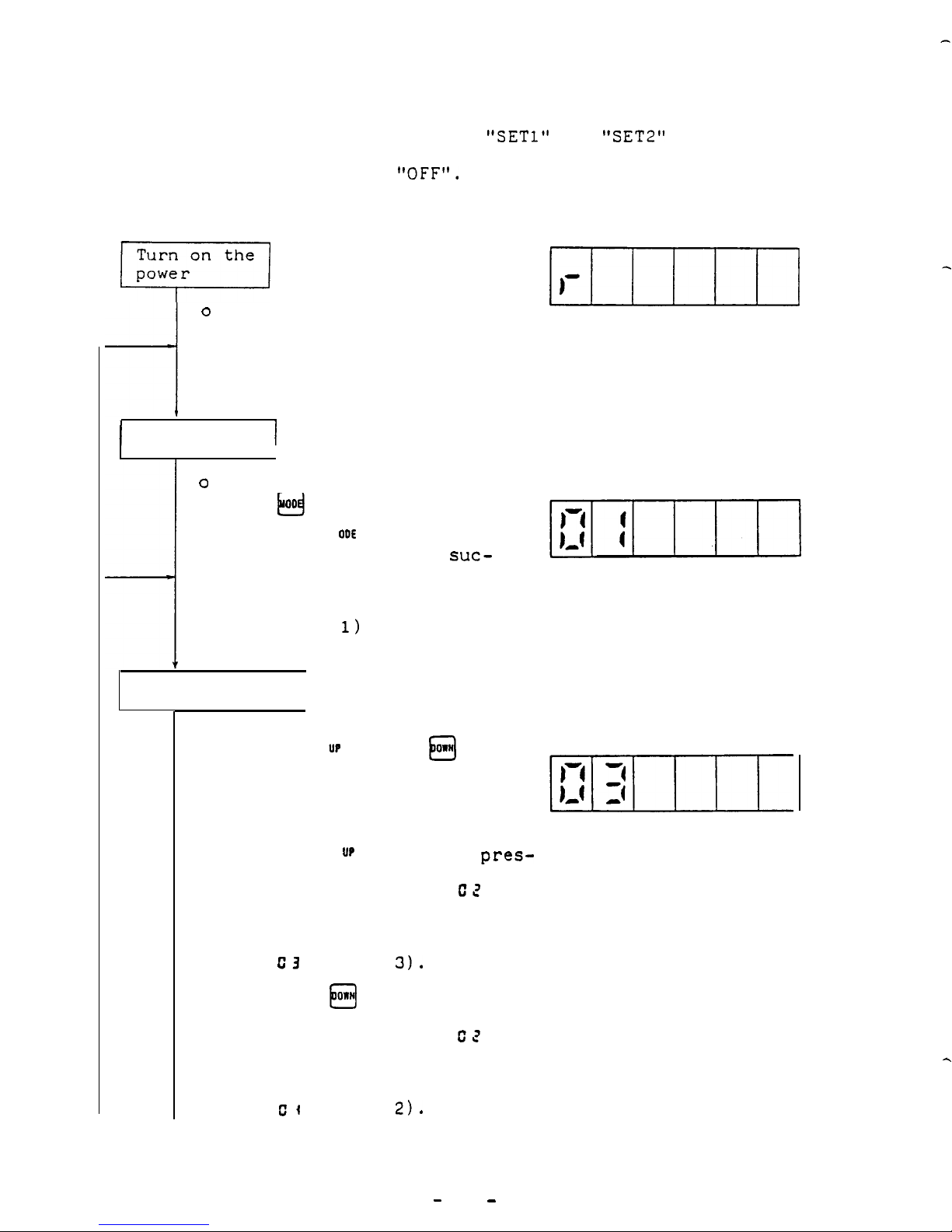
(6) Parameter setting
To specify parameter, set
"SETl"
and
"SET2"
(machine ready
for operation) to
"OFF".
p+xj
Unless alarm occurs, speed
BIIIII
A
0
is displayed in operation
status mode by the readout
ADD
DATA
(Fig. 1).
Fig. 1
SPEED display
I
Select mode.
1
o
Mode
when
Ex.:
changes step by step
k-3
00
switch is pressed.
When
El
ODE
switch is
pressed 3 times
suc-
cessively, display
mode changes from op-
eration status mode
ADD
DATA
(Fig. 1) to parameter (1)
mode' (Fig. 2).
Fig. 2
Select address.
J
o Address can be selected by
pressing UP and/or
0"~
switches.
0
Q
When address is selected,
the data at that address is
displayed.
Ex.:
When
up
0
switch is
pres-
Fig. 3
sed while display is as
shown in Fig. 2, CZ appears.
Another one touch of
switch causes display of,
c3
(Fig.
3).
When
OnH0switch is pres-
sed while display is as
shown in Fig. 3, CZ ap-
pears.
Another one touch of
switch causes display of
CI
(Fig.
2).
-
24
-
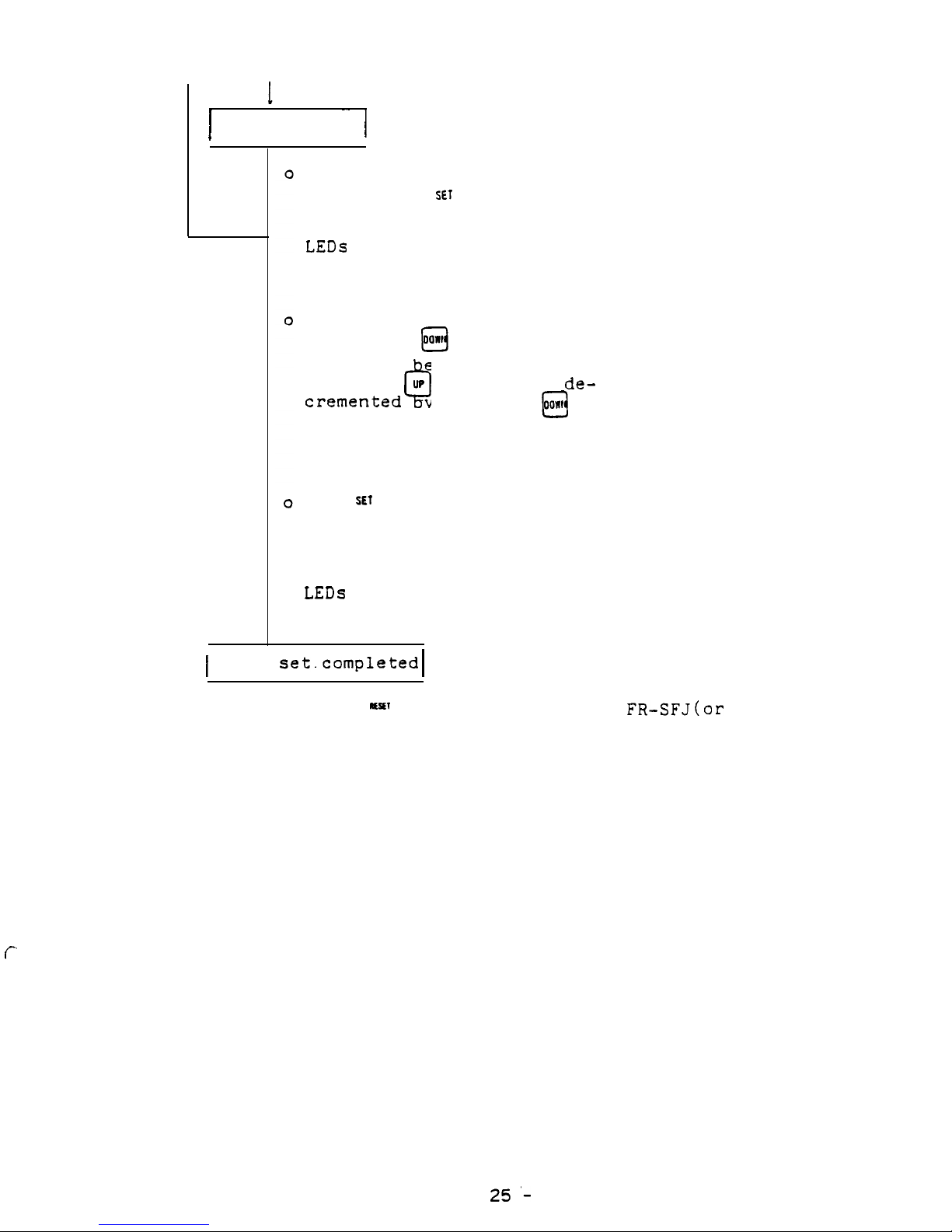
I
Data rewrite
~~
I
To rewrite previously set
data, press
SET
switch.
0
When the switch is pressed,
LEDs
ADD flickers indicating that data can be rewritten.
Set desired data by pressing
0
UP
and/or
oawt
switches.
Cl
Value can
e incremented by
pressing
0
UP
switch, and
decremented
switch.
y pressing
@j
Value changes continuously
while switch is held down.
When
SEf
switch i's pressed
0
again,
newly set data is
stored.
After the switch is pressed,
LEDs
ADD light continuously.
1
Data
set.completed
1
o Press
~ESU
switch and reset the FR-SFJ(or turn off and
0
then on the power).
Now data setting has been completed.
f-
-
25'-
3.4
Spindle control monitor on NC CRT display . . . when FR-SFJ is
connected to M300 CNC through bus line
Since display (format, content,
etc.) and setting method dif-
fer from NC to NC,
refer to the instruction manual for your
NC system.
Typical examples of NC CRT display are described here.
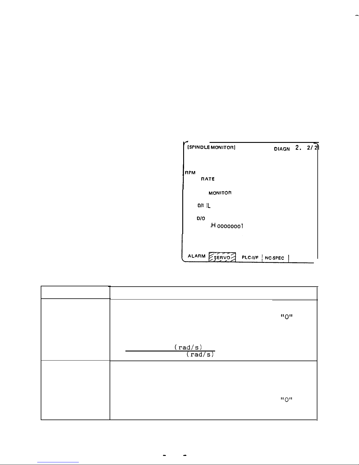
3.4.1
Status display
For status display, "SPINDLE
MONITOR" is selected from
the menu.
For use of this display
f
-(SPINDLE MONlTOn]
DIAGN 2. 21
GAIN
10.0
function,
FR-SFJ should be
I
DROOP
nPM
line.
connected to NC through bus
I
LOAD
nATE
80
ALARM NO.
46 23
DATA BIT
MONlTOn
76543210
o/I IL
oooooool
H
ollooooo
0'0
Looololoo
~Hoooooool
123456
6000
Display
GAIN
DROOP
Description
Position control loop gain is displayed.
When position control loop is not used,
"0"
is
displayed.
The standard position control loop gain is,
Motor speed
(rad/s)
Response delay
(rad/s)
= 10
Error in true spindle angle from referenced
spindle angle is called "droop".
Droop is expressed in number of pulses.
When position control loop is not used,
"0"
is
displayed.
-
26
-
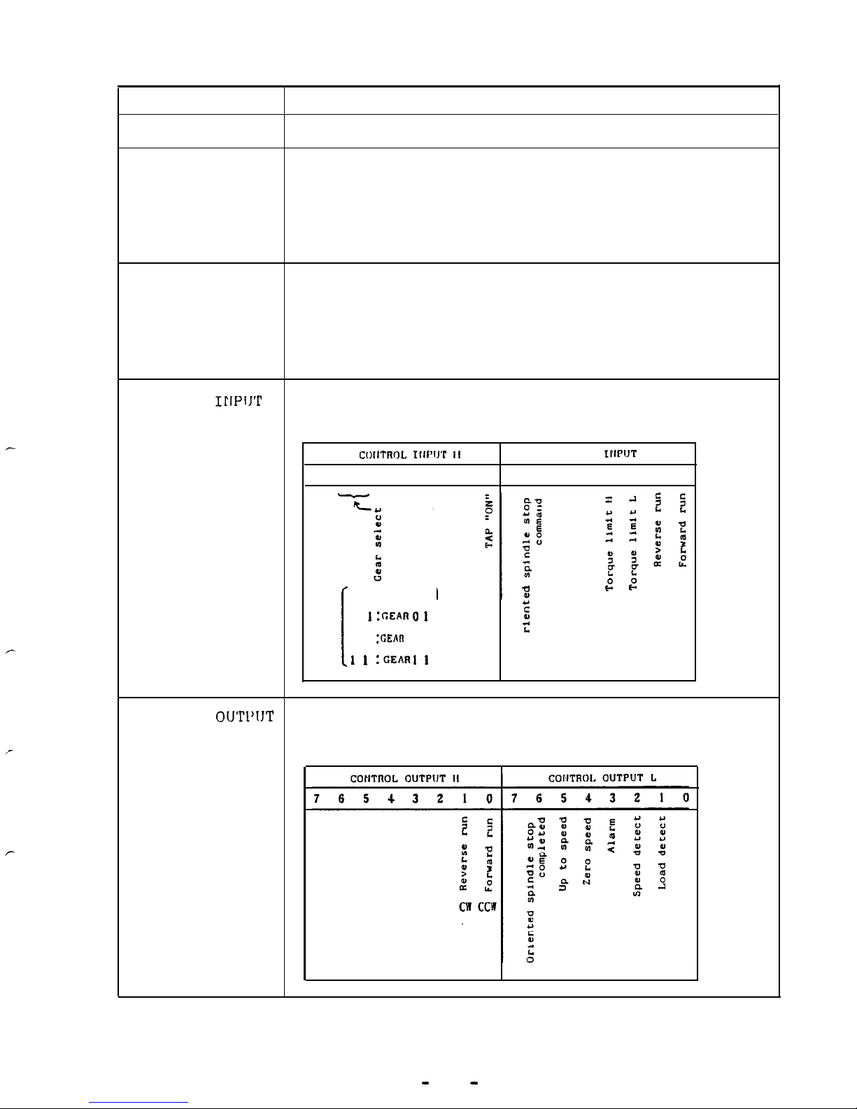
Display
Description
MOTOR SPEED
True motor speed is displayed in rpm.
MOTOR LOAD
Load is displayed in ratio(%) to motor rated output (capacity).
The output rated for 30 min. is 100%.
Range of display is from 0 to 120%.
SPINDLE ALARM
If fault occurs with spindle amplifier, alarm
is displayed with code No. (current alarm and
previous alarm are displayed).
For alarm contents,
refer to Appendix 2.
CONTROL
I!IPiJT
Signal input to spindle amplifier is displayed
by bit.
CI)IITROL IIII’IJ’P II
CONTROL
IWUT
L
7654321076543210
0 I
:c;EAnO 1
1
I
-3
2 :
,”
5
II L SRISRN
z
1 0 :-An 1 0
0
1 1 :GEARI
I
CONTROL
OUTl'lJT
Signal output from spindle amplifier is display-
ed by bit.
-
27
-
 Loading...