

Page 1
AC SPINDLE
USA-E99991-075-*
DRIV
TROUBLESHOOTING
,
i
./’
{‘Z
i
]
._
ADVANCED
MITSUBISHI
AND
EVER AOVAkCfNG
ELECTRKZ
Page 2

1.
Troubleshooting
1.1
1.1.1
1.1.2
Status display and diagnosis . . . . . . . . . . . . . . . . . . . . . . . . .
Status display and diagnosis from spindle amplifier.
Status display and diagnosis from NC . . . . . . . . . . . . . . .
. . . . . . . . . . . . . . . . . . . . . . . . . . . . . . . . . . . . . . . . .
1.2 Checking method and countermeasures of trouble
classification A .._..................................
1.2.1
When the amplifier is turned on at the first time,
it does not correctly work
. . . . . . . . . . . . . . . . . . . . . . . .
1.2.2 The motor which has normally rotated stops
. . . . . . . . . . . . . . . . . . . . . . . . . . . . . . . . . . . . . . . . . . .
Although an
after turning on and off the power
1.2.3
abruptly
The equipment does not work in occasions.
orientation stop position deviates.
alarm appears,
or resetting the equipment, the equipment normally
. . . . . . . . . . . . . . . . . . . . . . . . . . . . . . . . . . . . . . . . . . . . . .
1.3
1.3.1
works
Checking method and remedy of trouble classification
B
.
..I................................................
When the power is turned on, the display of the
operation panel does not appear at all . . . . . . . . . . . . .
1.3.2
When the power is turned on, the display on the
operation panel does not indicated the speed in
the status display mode (as shown in the following
. . . . . . . . . . . . . . . . . . . . . . . . . . . . . . . . . . . . . . . . . . . .
1.3.3
figure)
An alarm appears ont he display on the printed
circuit board (SF-CA card) of the amplifier . . . . . . . .
1.3.4
1.3.5
The motor does not rotate . . . . . . . . . . . . . . . . . . . . . . . . . .
The motor does not rotate at a speed being
specified
. . . . . . . . . . . . . . . . . . . . . . . . . . . . . . . . .
The
. . . . . . . . .
1
5
5
10
13
13
15
16
17
17
18
20
41
43
1.3.6
1.3.7
1.3.8
The motor vibrates and is getting noisier during
rotations . . . .
.._...._._........_...................
The motor overshoots in speed or hours . . . . . . . . . . . . .
The cutting force degrades . . . . . . . . . . . . . . . . . . . . . . . . .
44
46
47
Page 3

1.3.9 The orientation of the spindle is not correct . . . . . .
1.3.10 The acceleration/deceleration time increases . . . . . . .
1.3.11 The speed detection signal, up to speed signal,
or zero speed signal is not issued . . . . . . . . . . . . . . . . .
1.3.12 The tapping operation cannot be correctly performed. 55
1.3.13 The threading operation cannot be correctly
performed
. . . . . . . . . . . . . . . ..I...........
. . . . . . . . . . . . .
48
53
54
57
2. Checking and replacing parts
2.1
2.2
2.3
2.4
2.4.1
2.4.2
2.4.3
2.4.4
2.5 Checking transistor module (This method is the same
2.6
2.7
2.8
2.9
2.9.1
2.9.2
Replacing fuses
Replacing thermal protectors
Replacing amplifier cooling fan
Replacing printed circuit board
Replacing SF-PW module
Replacing SF-OR or SF-10 card
Replacing SF-TL card
Replacing SF-CA card
both in the power side and regeneration side)
Checking diode stack
Replacing transistor module and diode stack
Replacing motor cooling
Adjusting and replacing motor built-in encoder
Adjusting printed circuit board
Replacing encoder and printed circuit board
......................................
.................................
............................
.........................
......................
......................
.............................
......................
...............................
...............................
........
..........
..............................
....................
........
.......
58
59
59
59
61
61
62
63
64
65
68
70
71
74
74
77
3. Spindle orientation control circuit . . . . . . . . . . . . . . . . . . . . .
3.1
3.1.1 Spindle orientation using magnesensor (1 point) . . . . 80
3.1.2
3.2
3.2.1 Where the speed selection signal function is
3.2.2 Where the equipment is linkedwith the NC through
Structure . . . . . . . . . . . . . . . . . . . . . . . . . . . . . . . . . . . . . . . . . . . .
Spindle orientation using encoder . . . . . . . . . . . . . . . . . .
(4096 points,
Control circuit and parameter setting . . . . . . . . . . . . . . . .
provided (SF-OR card)
the bus . . . . . . . . . . . . . . . . . . . . . . . . . . . . . . . . . . . . . . . . . . . .
with index function)
. . . . . . . . . . . . . . . . . . . . . . . . . . . . . .
79
80
82
84
84
89
Page 4

3.2.3 Where the equipment is linked with the NC using
analog or digital signals ..........................
3.3 Mounting position detector
3.3.1
3.3.2
3.4
3.4.1
3.4.2
3.5
3.5.1
3.5.2
In the case of magnesensor type ....................
In the case of encoder type ........................
Adjustment ...........................................
In the case of magnesensor .........................
Encoder type .......................................
Operation mode and motions ...........................
In the case of magnesensor .........................
Encoder type .......................................
...........................
96
97
97
104
106
106
110
113
113
115
4. Adjusting synchronous tap ...............................
4.1
4.2
Appendix 1
Appendix l-l
Appendix l-2
Appendix l-3
Setting parameters ...................................
Checking operation ...................................
Machine Connection . . . . . . . . . . . . . . . . . . . . . . . . . . . . .
Power connection . . . . . . . . . . . . . . . . . . . . . . . . . . . . . 120
Connection with motor (for standard motor) . . . 122
Machine connection . . . . . . . . . . . . . . . . . . . . . . . . . . . 122
(without orientation (standard))
Appendix l-4
Appendix l-5
Machine connection . . . . . . . . . . . . . . . . . . . . . . . . . . . 123
Machine connection(Bus linkage with NC) . . . . . . 124
(Magnesensor orientation (1 point)
specification)
Appendix l-6
Machine connection(Bus linkage with NC) . . . . . . 125
(with encoder synchronous tap,
orientation
(4096 points) specification/indexing
funtion)
Appendix l-7
Machine connection . . . . . . . . . . . . . . . . . . . . . . . . . . .
(with encoder orientation rather than NC)
(with 4096 point orientation/indexing function)
117
117
118
120
126
Appendix 2
Appendix 2-l
Cable Connections . . . . . . . . . . . . . . . . . . . . . . . . . . . . . .
Cable connection . . . . . . . . . . . . . . . . . . . . . . . . . . . . .
(without orientation (standard)
1
127
127
Page 5

Appendix 2-2
Appendix 2-3
Cable connection .............................
Cable connections (Bus linkage with NC)
...... 129
128
Appendix 3
Appendix 4
Appendix 5
Cable and Connector Specifications
Main Circuit Configuration .....................
Spindle Part Layout ............................
.............
(Excluding printed circuit boards)
Appendix 6
Control Circuit Printed Circuit Board Part
Layout .........................................
Appendix 7
Appendix 8
Appendix 9
Appendix 10
Appendix 11
Appendix 12
Reference:
Major Part Table ...............................
Display Lamps (LED diodes) .....................
Check Terminals ................................
Parameter Setting List and Short Pin Switch . . .
Structural Components . . . . . . . . . . . . . . . . . . . . . . . . .
Maintenance Instruments . . . . . . . . . . . . . . . . . . . . . . .
Setting and Adjustment
1.1 Set switches, set pins, and variable resistors
1.1.1
1.1.2
SF-CA card
SF-GR card
.........................................
.........................................
.......
130
138
139
144
148
154
155
169
172
175
176
176
179
1.1.3
1.2
1.2.1
1.2.2
SF-TL card .........................................
Setting parameters
Display and set switches (on SF-CA card)
Setting parameters from spindle amplifier
...................................
...........
..........
1.2.3 Setting parameters from NC (On 9" CRT screen)
1.3
Adjusting speed and load meter
.......................
1.4 Setting and adjusting spindle orientation control
circuit
..............................................
......
180
182
183
185
204
214
214
Page 6

1 Troubleshooting
Troubleshooting
1.
If any trouble occurs, before checking the cause, make sure
to read and follow the contents of Table 1.1, "Precautions"
for safety,
Table 1.1 Precautions for safety
o
After turning off the power,
the controller.
tion lamp LED 10 (SF-CA card) puts off, conduct the maintenance and inspection work (waiting for 3 minutes or
more).
0
An electric shock may result in a death accident.
Regardless of whether the power supply is grounded or
not,
exposed to a high voltage,
apparatus.
When installing any test apparatus on a portion to be
tested,
Generally, when conducting a test,
of any test apparatus.
be applied between the test apparatus case and the
ground,
repairing it, take care of it.
o
While the power is supplied to the equipment or when the
equipment is operated,
circuit board.
o
Do not put on a loose close which may be caught by the
rotating portion of the equipment.
since each component of the equipment may be
take care not to touch any portion being grounded.
when operating the equipment while adjusting/
After checking that the power indica-
Thus,
do not attach/detach any printed
Otherwise,
do not immediately touch
carefully select and use test
do not ground the case
because a high voltage may
the equipment may be damaged.
1
Next,
Items upon Occurrence of Trouble".
with Service Department of Mitsubishi Electric.
thoroughly check the contents of Table 1.2, "Check
They will help you contact
-l-
Page 7
/
1 Troubleshooting
/
Table 1.2
Check items upon occurrence of trouble
Check what alarm the alarm display of theamplifier indicates.
In addition, check old alarms in the alarm mode
of the indication lamp (see Appendix 8).
At which of phase R, S, and T a fuse is blown?
(Control circuit input fuse)
Does the trouble or fault repeatedly occur?
Is the ambient temperature and temperature in the
panel normal?
(Is that 55°C or less?)
During what situation does the trouble or fault occur?
During acceleration, deceleration, or constant speed?
At what speed it occurs?
Does the trouble or fault differ between the forward
rotation and reverse rotation?
Is there an instantaneous power failure?
Does the trouble or fault occur when a special opera-
tion or instruction is executed?
9
How often does the trouble or fault occur?
10
At what load situation does the trouble or fault occurs?
Whether a load is applied or removed?
Is a suspicious part replaced with a new one or a
11
temporary repair conducted against the trouble or
fault?
12
13
How many years has the equipment been operated?
Is the power voltage normal?
Does it vary remarkably depending on the time zone?
By referencing the trouble classification shown in Table 1.4,
check the power voltage listed in Table 1.3 before conducting
troubleshooting and countermeasures.
-2-
Page 8
1
1 Troubleshooting
~1
Table 1.3
Checking
AC power voltage
Checking DC power
supply voltage on
printed circuit
board
Table 1.4
E;$-
cation
When the amplifier is powered on at the first
1
time,
The equipment which has normally worked does
2
not abruptly work.
A.
The equipment does not work in occasions.
The orientation stop position deviates from
3
the specific position.
lights,
then on the equipment or by resetting it.
Checking power voltage
Amplifier input pins
Xl, X2, X3, and E
Checking DC output
voltage at check
pins on SF-PW card
Trouble classification
Situation
it does not normally work.
Although an alarm
it is recovered by turning off and
See Appendix l-l
See Appendixes 5,
h(4),
and
g(4).
1
r-
1.2.1
1.2.2
1.2.3
When the power is turned on, the display of
the operation panel does not appear at all.
1
Alternatevely,
circuit board is not correct.
When the power is turned on, the display on
the operation panel does not indicate
2
tions in the status display mode (as shown in
B
the following figure).
)-
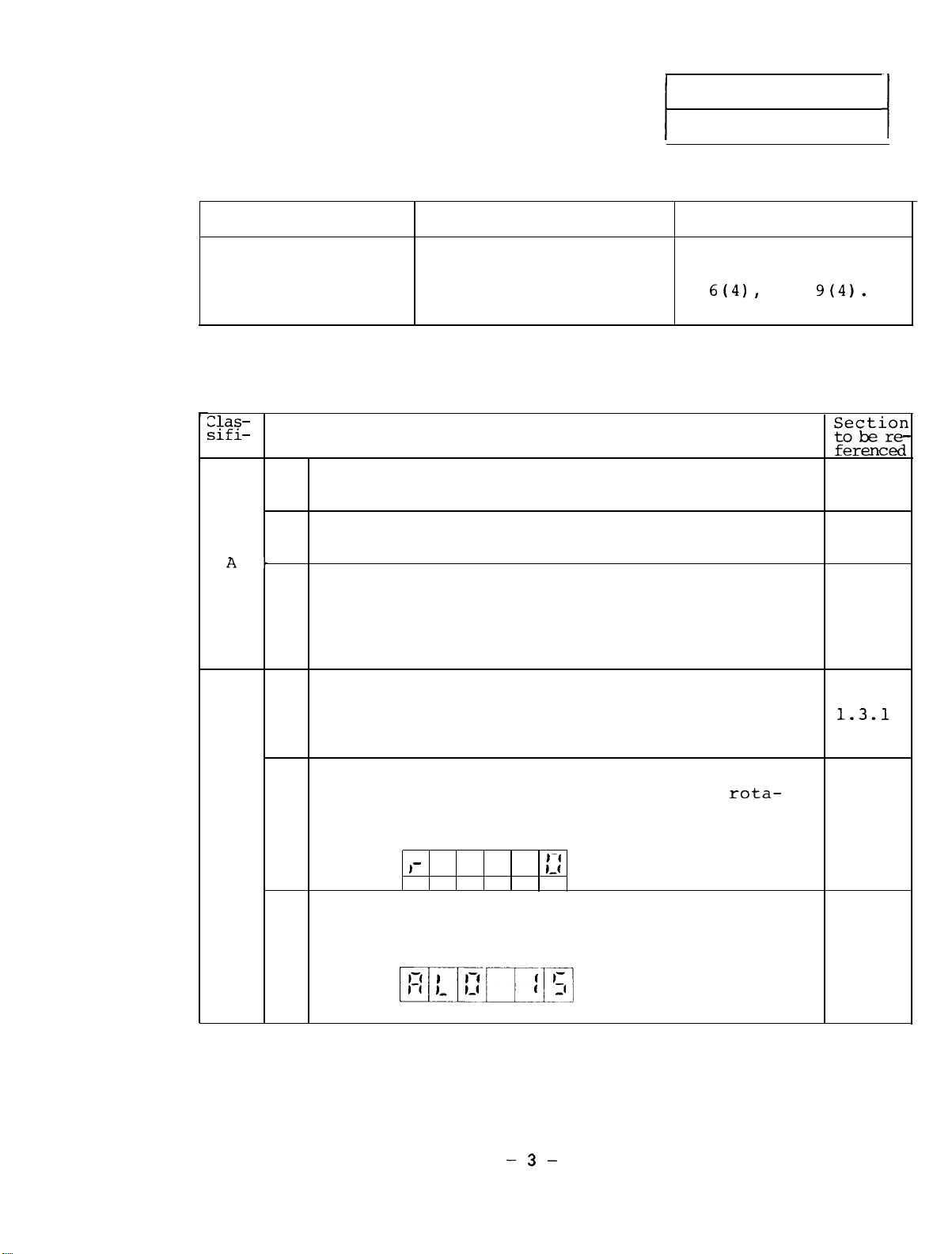
The display on the amplifier printed circuit
board (SF-CA card) indicates an alarm (as
shown in the following figure).
3
the DC voltage of the printed
rota-
::
Continued
on the next page.
1.3.1
1.3.2
1.3.3
-3-
Page 9
1 Troubleshooting
:kEi-
;ifiation
B
Situation
The NC CRT (spindle monitor screen) indicates
an alarm (as shown in the following figure).
4
Spindle alarm 15 01
5 The motor does not rotate.
The motor speed do not conform with that being
6
specified.
The motor vibrates with a large noise during
7
rotations.
8
The motor overshoots at speed or hunts.
9
The cutting force degrades.
The orientation of the spindle is not correctly 1 3
10
performed.
EcikiZ
ferenced
1.3.3
1.3.4
1.3.5
1.3.6
1.3.7
1.3.8
g
. .
The acceleration/deceleration time becomes
11
lonq.
The speed detection signal, up to speed signal, 1 3 11
12
or zero speed signal is not issued.
13 The tapping work is not correctly performed.
The threading work is not correctly
14
performed.
1.3.10
. .
1.3.12
1.3.13
-4-
Page 10
1.1 Status display and diagnosis The status display and diagnosis are executed with the
display and switches on the SF-CA card.
an NC and bus line,
the status display and diagnosis can
be executed on the NC CRT.
When linking
1.1.1
Status display and diagnosis from spindle amplifier
For instructions for operating the display and switches,
see Reference
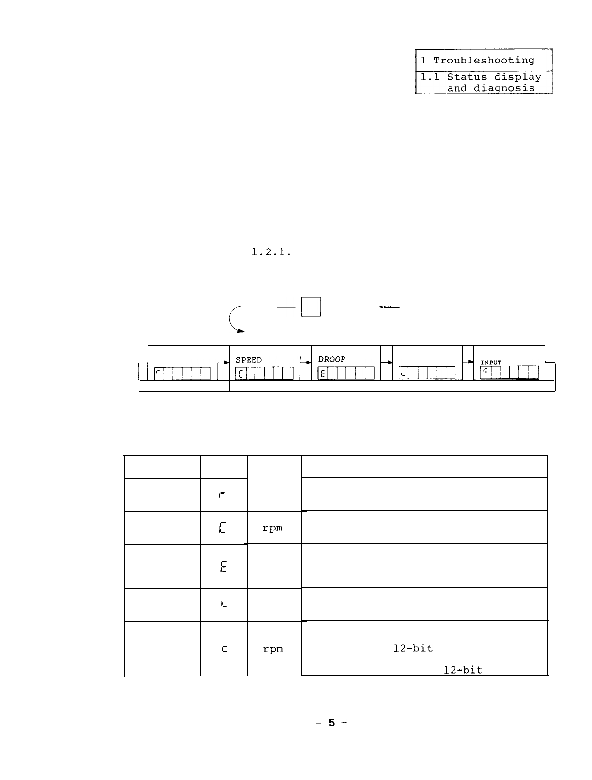
(1) Status display
SPEED
The following table lists the contents of the four types
of status display modes.
Item
SPEED
Code
I'
1.2.1.
Shift
REFERENCE
Unit
rpm
-I
DOWN UP
Represents the motor speed.
q
POSITION
___
Shift
LOAD
Description
3
SPEED
REFERENCE
7
REFERENCE
SPEED
POSITION
DROOP
LOAD
SPEED
REFERENCE
INPUT
1-
1,
-
1:
L
I-
_
rpm
Pulse
%
rpm
Represents the motor reference
speed.
Represents remaining pulses on the
deviation counter.
In the case of
reverse side pulse (negative number),
the decimal point indicator lights.
Represents the load status assuming
that 30-minute rating output is
100%.
Bus linkage with NC . . . 2-port data
of speed reference inputted from NC
S analog . . .
12-bit conversion value
of A/D converter
Digital control . . . 12-bit value
-5-
Page 11
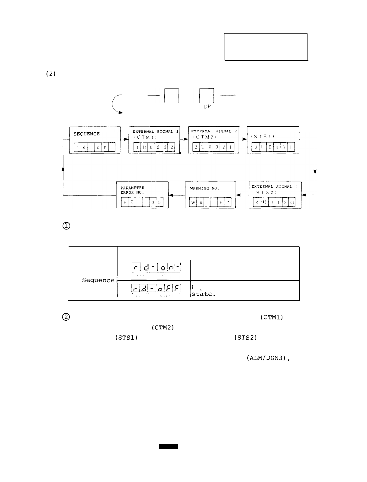
(2)
Diagnosis
Shift
1 Troubleshooting
1.1 Status display
and diagnosis
-
Shift
DOWN
LP
‘,
0
The following table lists the contents of the
sequence diagnosis.
I
Item
Sequence
1
Display
1
k, ,j - j III!
MM__
\ ,I,
II
l-l ] - j
Description
Represents the ready
state.
Represents the non-ready
3
EXTERNAL SIGNAL 3
Check the contents of the external signal 1
0
external signal 2
signal 3
(STSl)
(CTM2)
of input signals and external
and external signal 4
(STS2)
of output
signals by comparing them with the following table.
(Note) On the NC spindle monitor display
(ALM/DGN3),
the external signal 1 and external signal 4 are
checked as a control input and control output,
respectively.
-6-
(CTMl)
and
Page 12
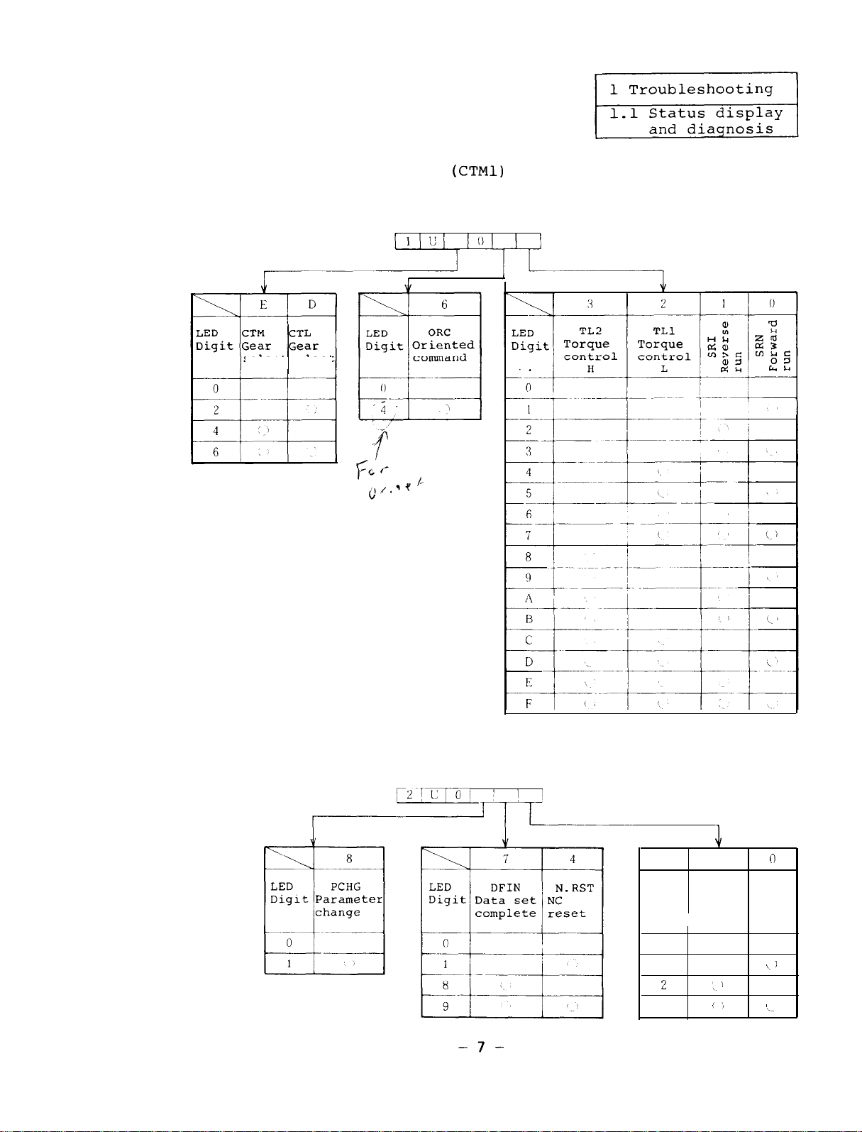
(a) External signal 1
(CTMl)
Check the contents of signals by each digit of LED
using the following table.
selectselect
(b) External signal 2 (CTM2)
Check the signal contents by each digit of LED using
the following table.
[2/1;10/
LED
Digit Servo Ready
SVON
ON
0
1
:!
3
J
1
: '
'j
n
RDY
ON
k. J
I_
Page 13
1
Troubleshooting
1.1 Status display
and diagnosis
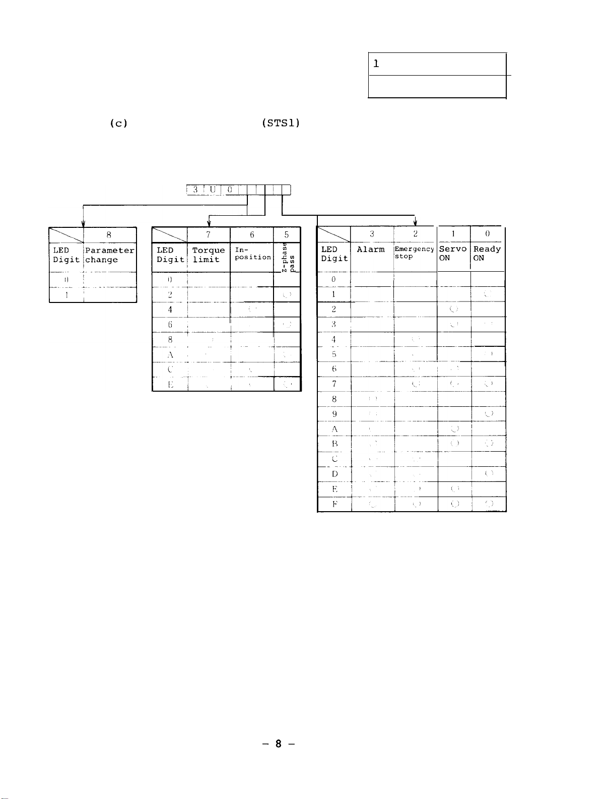
(c)
External signal 3
(STSl)
Check the signal contents by each digit of LED using
the following table.
1
Servo Ready
ON
f
0
ON
-8-
Page 14
1 Troubleshooting
1.1 Status display
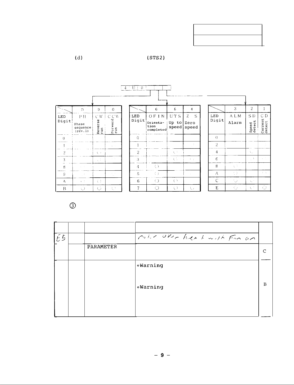
(d)
External signal 4
(STS2)
Check the signal contents by each digit of LED
using the following table.
and diagnosis
@
There are three types of warnings as listed in the
EO
IPF
E4E7WPE
NCE
table.
INSTANTANEOUS
POWER FAILURE
PARAMETER
SETTING ERROR
NC EMERGENCY
STOP
Warning which is issued when the
power voltage temporarily drops.
/cl'
i.. y
12vJr Lp> /- "",/.A /c_* [,A
Warning which is issued when a
parameter value exceeds the allow-
able range
OWarning which is issued when an
emergency stop signal is inputted
from the CNC in bus linkage with
the M300 series CNC.
owarning which is issued when an
emergency stop signal is inputted
from the outside while the external emergency stop signal is
validated with the related para-
meter being set.
C
-9-
Page 15
1 Troubleshooting
1.1 Status display
and diagnosis
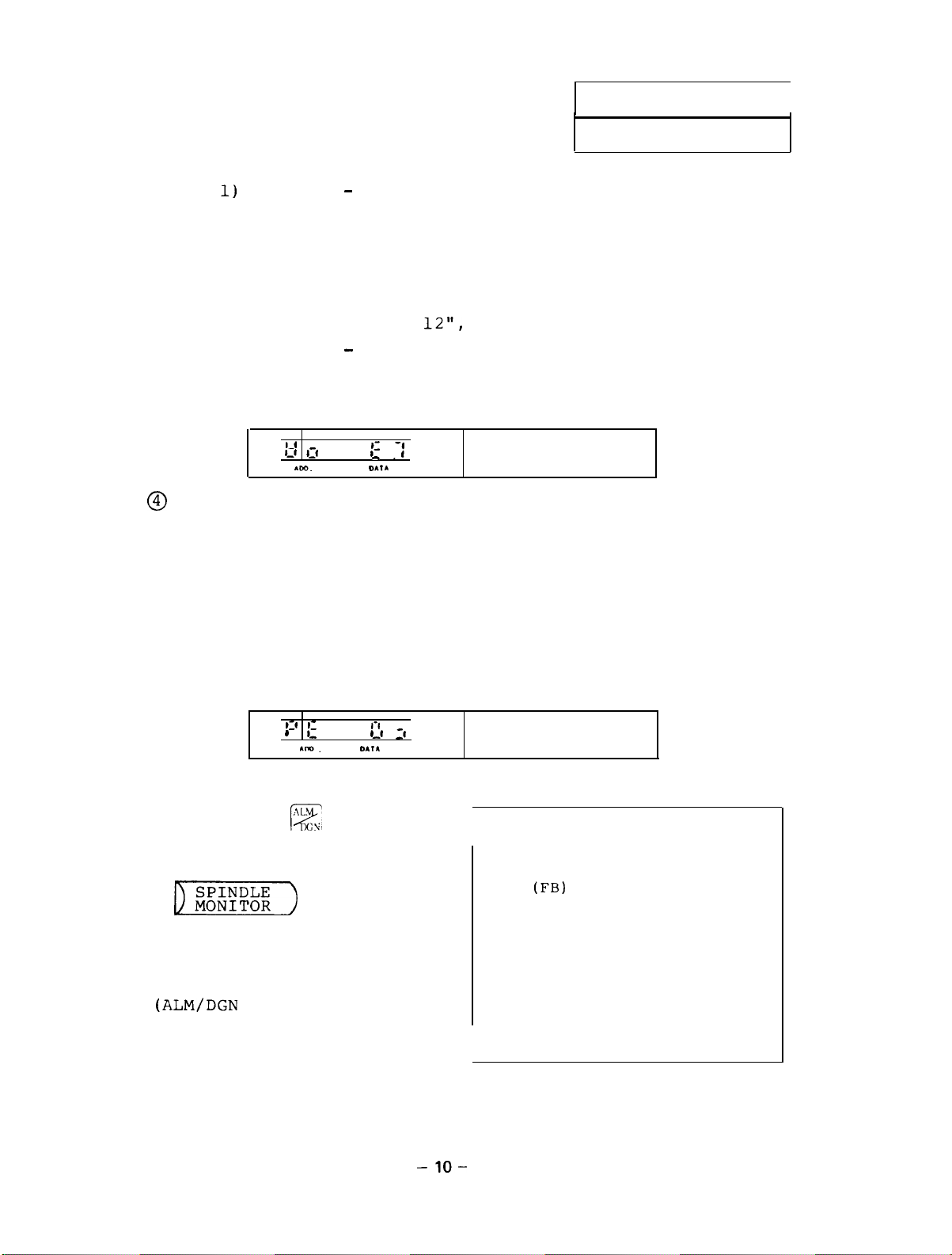
(Note 1) Motion B - The motor decelerations and stops
with regenerative braking and then base
shut-off takes place.
Whether to open
the trouble signal contact FA-FC can be
selected with a parameter.
Nos.
Motion C
11 and
Only the alarm lamp lights, but
-
12",
Appendixes l-4 and l-5.)
(See
"CON Pin
the operation continues.
(Note 2) An example of the display is as follows.
1.1.2
1-4
I-1 111
rm.
@
The parameter error No. represents which parameter
;'
_ .-1'
DA,&
NC emergency stop
is defective when the alarm No. 37 (PE, parameter
error) occurs.
(Note 1) If a multiple of parameters is defective, check
and correct the parameters in accordance with
the parameter error Nos. until the alarm No.
37 does not occur.
(Note 2) An example of display is as follows:
19 :'
’ ^
Am.
Status display and diagnosis
Pressing the
E,
is one of function
selection keys and the
D))
key
which is one of menu
keys causes the following spindle monitor screen
(ALM/DGN
3) to appear.
l-l
I-
,,I :I
D.,l
which
Indicating parameter
error No.
from NC
[SPINDLE MONITOR]
GAIN
DROOP
Srpm
RPM
LOAD RATE
ALARM NO.
D/I L
D/O L
ALARM SERVO
(FB)
H
H
00 00
76543210
00000100
00000001
00000100
00000010
SPINDLE
MONITOR PLC-I/F
ALM/DGN
10.0
675
100
100
40
3
-lO-
Page 16
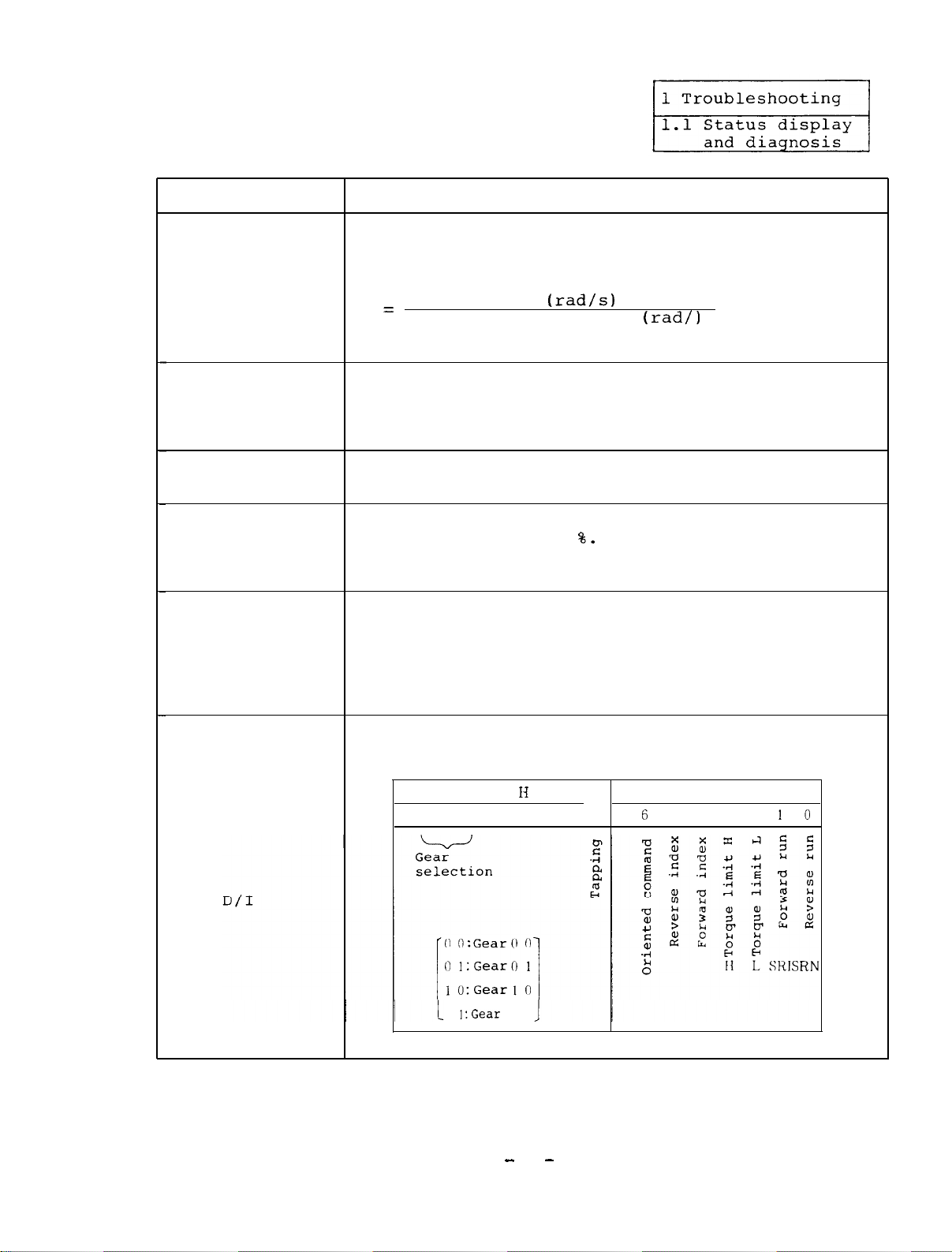
Display
Description
Represents the position loop gain state. It
represents 0 when no position loop is formed.
GAIN
Position loop gain is obtained from the equation
Motor speed
=
Followed delay error
(rad/s)
(rad/)
The standard value is 10.
An error of real spindle rotation angle against
POSITION DROOP
referred spindle rotation angle is named droop.
The unit is in pulses. When no position loop is
formed,
the position droop is 0.
RPM Represents the real motor speed.
(Motor speed)
The unit is in rpm.
Represents a ratio of load against the rating
MOTOR RATE
output.
The unit is
output is 100%. The motor rate is in the range
The 30-minute rating
8.
0 to 120%.
Represents the contents of alarms which occurred
in the spindle amplifier this time and last time
ALARM NO.
with code numbers.
However,
the last alarm is
(Spindle alarm) the smallest number alarm which differs from
this time alarm.
For details of the contents
of alarms, see 1.3.3.
Represents an input command to be issued to the
spindle amplifier corresponding to bits.
D/I
7
6 5 4 3 2 10 7 6 5 4 3 2
1
1:Gear
13
1 1
D/I L
10
Continued on the next page.
-
11
-
Page 17
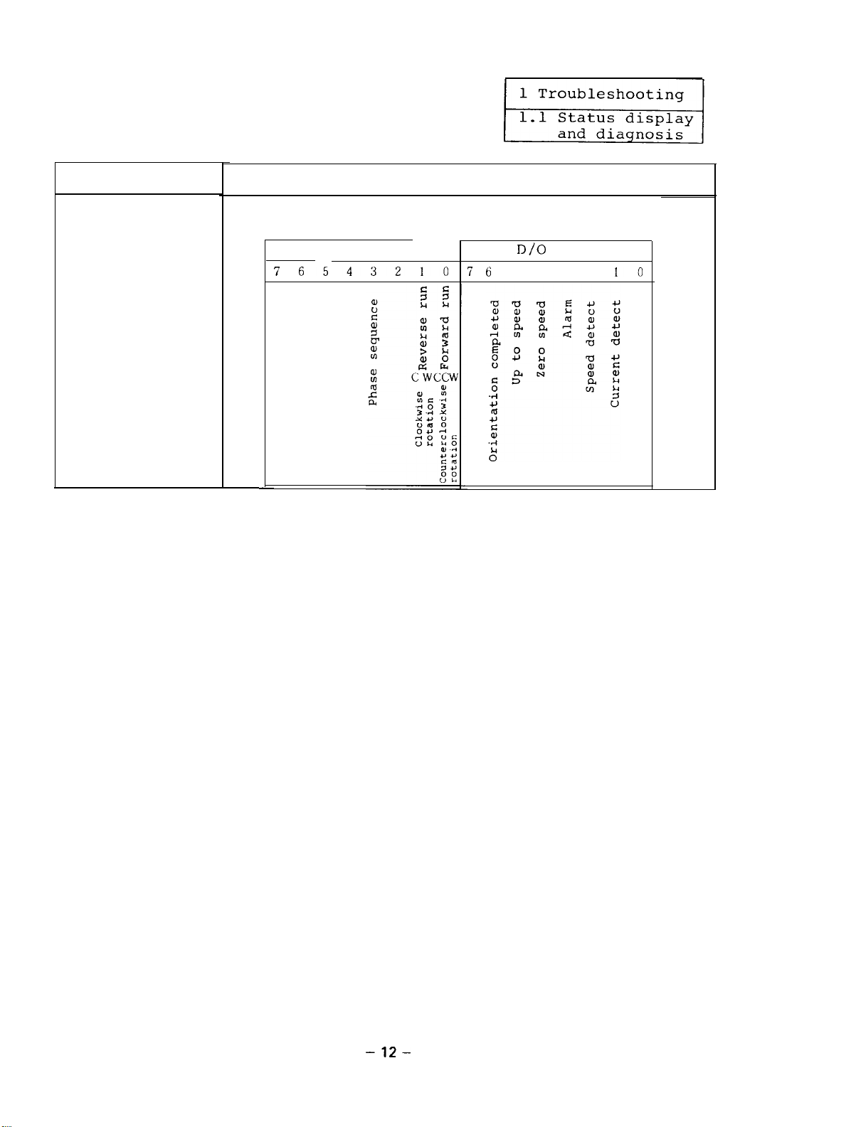
Display
Description
Represents a control output being outputted from
the spindle amplifier corresponding to bits.
D/O
D/O H
7
6543210
-
7 6
D/O L
5 4 3 2
10
-12-
Page 18
1 Troubleshooting
1.2 Checking method and countermeasures of trouble classification A
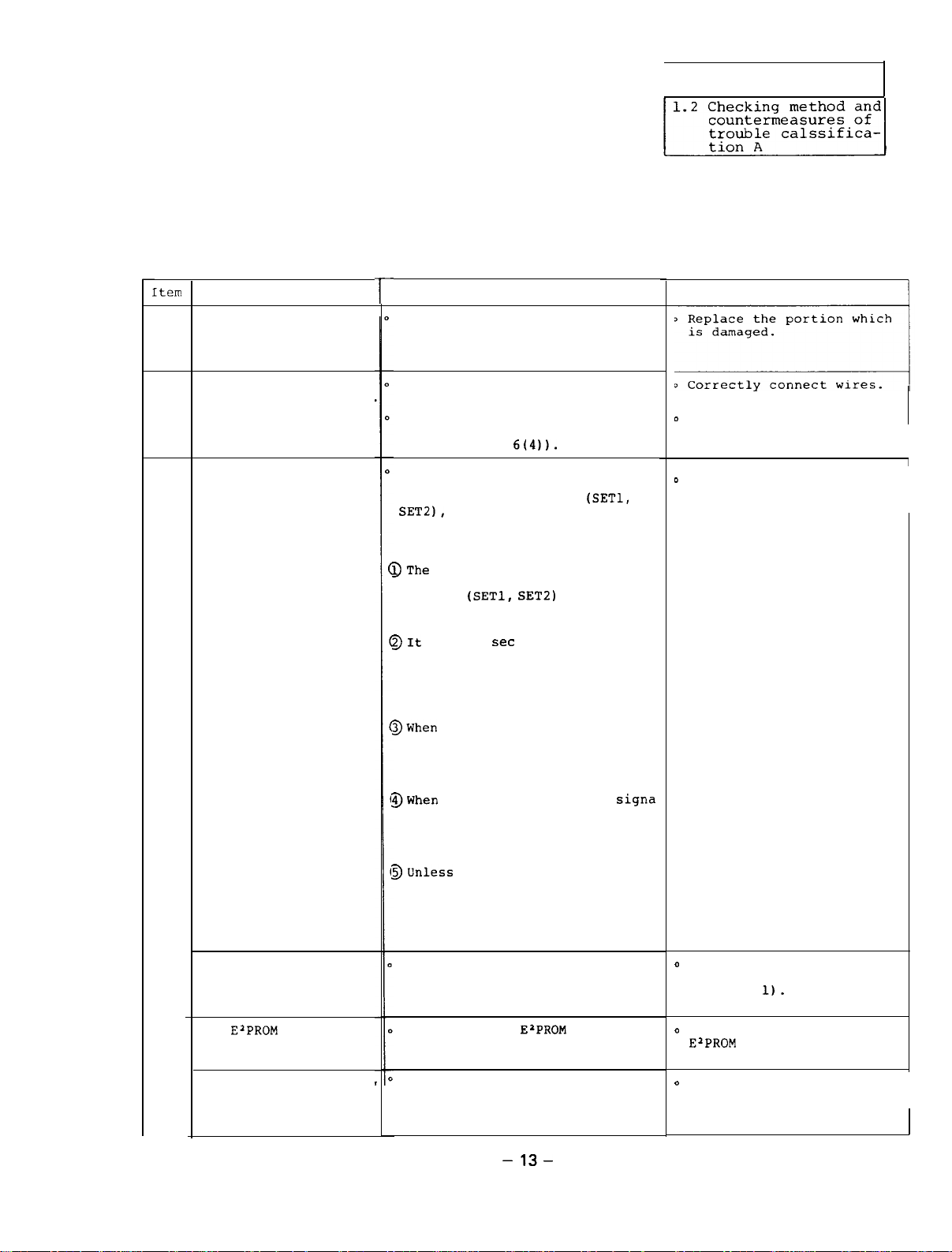
1.2.1 When the amplifier is turned on at the first time, it
[tern
The amplifier is
knocked and damaged
1
when the equipment is
operated or installed.
The external wiring
is incorrect or broken
2
The signal ON/OFF
sequence is incorrect.
3
-The ground wiring is
not conducted.
4
The
5
incorrect.
The switch and setting
pins are incorrectly
6
set.
Cause
ElPROM
number is
l-
Visually check there is an abnormal portion on the amplifier.
Visually check the external wiring.
Check that the indication lamp
LED 1 on the SF-PW card lights
(see Appendix
Check the sequence among the NC
ready ON signal, spindle ampli-
fier CON1 ready signal
SETZ),
reverse rotation signal, and
orientation signal taking care
of the following items.
DThe
NC ready ON signal and
spindle amplifier CON1 ready
signal
ready when both the signals are
turned on.
BIt
takes 1
command of the forward rotation
signal,
or orientation signal is
received after the ready ON
state.
BWhen
both the forward rotation
signal and reverse rotation
signal are turned on at a time,
the motor does not rotate (it
becomes the DC exciting state).
BWhen
the forward rotation
or reverse rotation signal is
inputted when the speed reference is 0,
DC exciting State.
BUnless
Check the ground wirings of the
power,
shield ground wiring of the
detector command.
Check that the
conforms with the amplifier mode
name and motor type name.
Check the set positions of the
switches and setting pins by
comparing them with the attached setting pin list (Reference
1.11.
the forward rotation
signal,
or orientation signal is input-
ted the motor is in the free
run state where the base
shut-off takes place.
Check
6(411.
forward rotation signal,
(SETl, SET21
set
or more until tht
reverse rotation signal
the motor becomes the
reverse rotation signal
amplifier, and motor and
E'PROM
(SETl,
become
signa
number
-13-
Remedy
D
Replace the broken wire
with a new one.
0
Change the signal sequence.'
D
Correctly connect the
ground wirings (see
Appendix
o
Replace the incorrect
ElPROM
o
Correctly set the switches
and setting pins.
Continued on the next page.
1).
with a correct one.
Page 19
1
Item 1
Cause
Check
Remedy
The parameters are0 Check the parameters by comparing oCorrectly set the
incorrectly set.
7
them with the parameter list
vided by the machine manufacturer
pro-
meters.
(Reference 1.2).
The motor speed cannot DCheck that the phase sequence of . oCorrect the phase sequence.
a
be increased (the
alarm No.
23 occurs).
The motor does not
correctly rotate only
9
when the orientation
D‘ v,
and motor is correct.
1
Check and readjust the spindle orientation control
referencing Chapter 7.
and W between the amplifier
circuyt
stop takes place (a
runout
occurs).
The alarm disply
10
of the amplifier
)
Check the cause and take the proper remedy by referencing
Section 1.3.3 which describes the contents of alarms.
lights.
An alarm appears on
11
the NC CRT screen.
0
Check the cause and take the proper remedy by referencing
Section 1.1.2 which describes the status display and diagnosis.
The
LED3(red)
amplifier lights.
12
The spindle does not
rotate.
13
on the
0
ROM is defective or incorrectly attached.
0
The power supply (SF-PW Module) is defective.
o
No data is transferred from NC in bus linkage state.
o
Check that the spindle parameters
o
Check that the connection constants
slimit
and smax are not 0.
(MCW
and inching) of the
connection parameters are not 0.
para-
by
-14-
Page 20
1 Troubleshooting
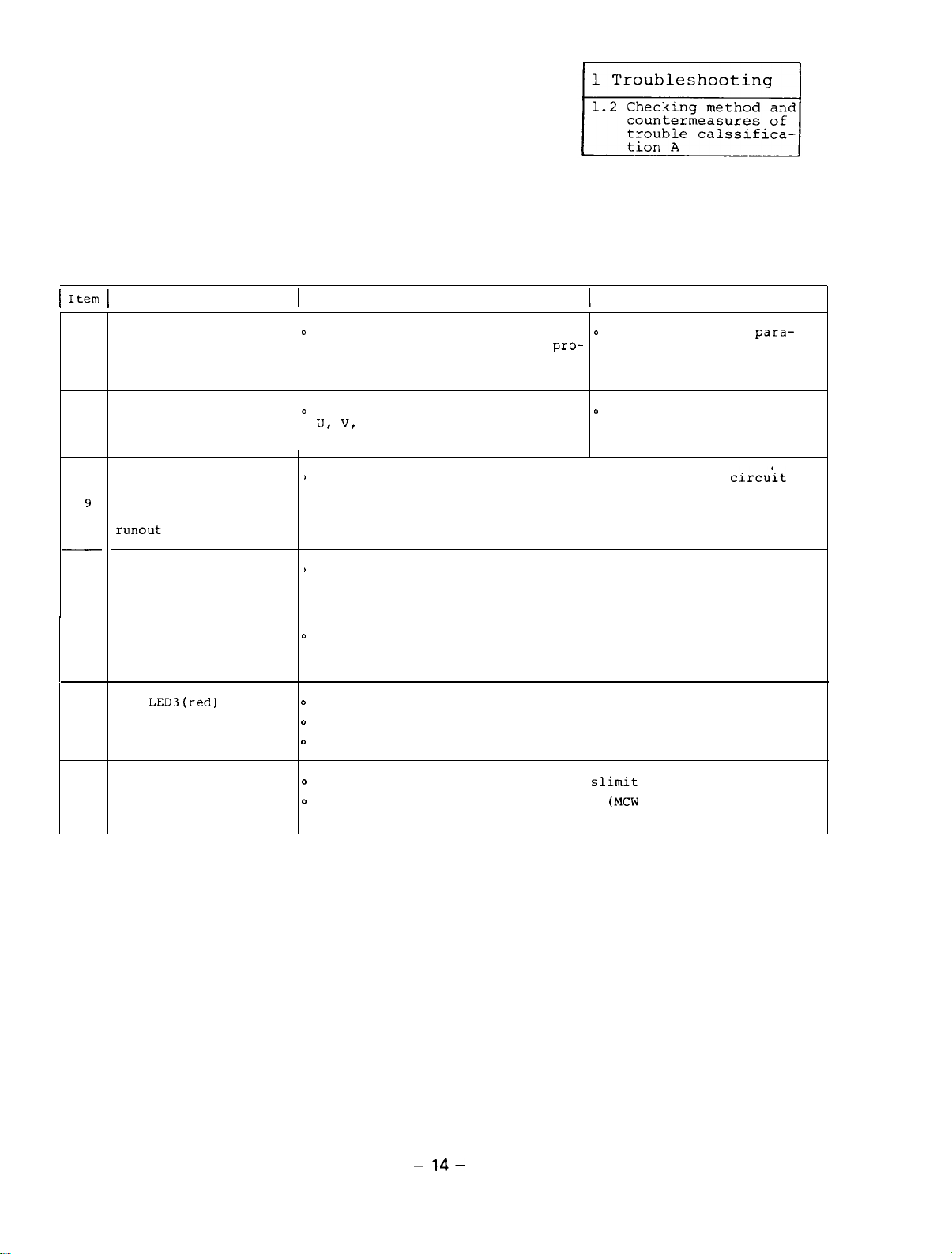
1.2.2 The motor which has normally rotated stops abruptly.
Item
The fuse
or
Alternatively, the NF
(CBl)
1
The power voltage is
out of the range.
2
An input signal from
the sequencer is
mal.
3
The input signal from
the NC is abnormal.
4
Cause Check
F3)
is blown.
is tripped.
(Fl,
F2, and/
abnor-
Remedy
0
Check the conductivity using
a circuit tester (see
Appendix 5).
0
Check the power voltage using0 Adjust the related control
the circuit tester.
(See Table 1.3)
0
Check each bit of the
external signals 1 and 2 in
the diagnosis mode of the
amplifier indicator. received.
For example, the bits of
ready ON,
and reverse rotation signals.
(See Section
0
Check each bit of a control0 Conduct the same
input by referencing Section
1.1.2 which describes the
status display and diagnosis.
0
At the same time, check the
same items as the Item 3
above.
forward rotation,
1.1.1(2).)
0
Replace the fuse
and/or
(See Section 2.1).
0
After replacing the fuse
with a new one or resetting
the NF,
tion takes place, see Section 1.2.3.
so that the input power
votlage is in the specified
range.
0
Check the input signal where
bits are abnormal so that
the signal is correctly
measures as the Item 3 above,
F3)
with a new one.
if the same situa-
(Fl,
F2,
counter-
The signal from the
encoder which contains
a motor is abnormal.
5
(Note)
The parameter 00 is valid just after 1 is set. Since the parameter 00 is cleared
when the power is turned off or the equipment is reset, after setting 1, immediately
input the speed reference and start command.
0
Set the parameter of the
amplifier as follows.
(Note) _
In an open loop state, input
the speed reference and
start command to rotate the0 If the above adjustment
motor at a slow speed and
check the signal from the
encoder. (See Section 2.9.) printed circuit board with
I 8 t-1
l-1 ,_I
I I I
:
0
Adjust the related control
by referencing Section 2.9
which describes the
ing procedure of motor
built-in encoder so that the
output signal is in the
specified level.
not be conducted, replace
the sensor section and
new ones.
adjust-
-15-
can-
Page 21
1 Troubleshooting
1.2
Checking method and
countermeasures of
trouble
tion
calssifica-
A
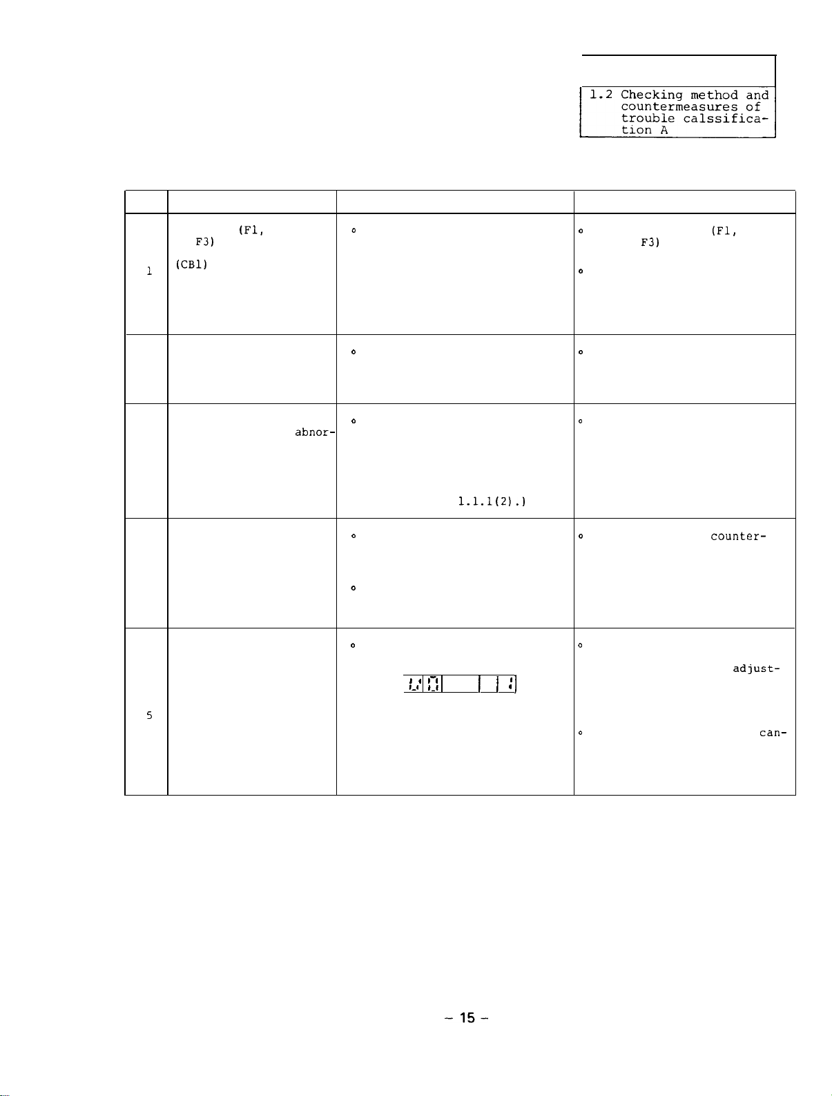
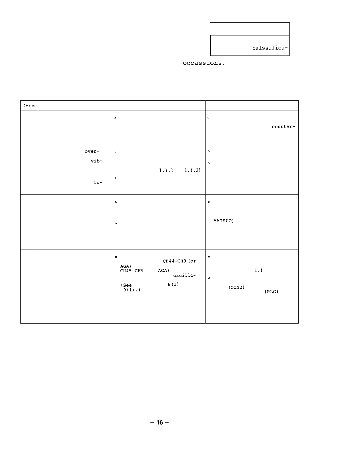
1.2.3
The equipment does not work in occassions.
tation stop position deviates.
appears,
after turning on and off the power or resetting
the equipment, the equipment normally works.
[tern
An instantaneous power
failure or voltage
1
drop of the input power
occurs. (Alarm No.101
The machine is
loaded instantaneously
due to affect of
rations and so forth. the status display.
2
(Note) This trouble
The equipment malfunc-
tions with a too large
noise.
(Power supply line)
3
Cause
over-
vib-
often occurs when
orientation is
correctly conducted.
in-
o
Check that an instantaneous
power failure occurred in
another facility in the same
plant.
0
Rotate the motor at a slow
speed and check that the
motor load changes through
(See Section
o
Check the backlash between
the spindle encoder and
spindle.
o
Check the voltage waveform
of the amplifier input pins
Xl, x2,
oscilloscope.
o
While removing suspicious
noise sources one by one,
check the voltage waveform
and find the real noise
source.
Check
1.1.1
or
and X3 with an
The orien-
Although an alarm
Remedy
0
Check the cause of the
instantaneous power failure
and take the proper
measures so that the same
situation will not occur.
o
Remove the cause of the load
change.
o
Adjust the related control
1.1.2)
so that the backlash becomes
small.
o
Place a serge killer near
the noise source.
(For example, 200 VAC,
DCR-2-12003-5041, made by
MATSUO)
counter-
The equipment malfunc-D Check the signal waveforms
tions by noise which
enters a signal from
the motor built-in
encoder.
4
at check pins
AGA)
for phase A signal and
CH45-CH9
B signal using an
scope.
(See
9(l).)
(Note) When measuring the
(or
Appendixes
waveforms, turn off the
power of the amplifier
before using the check
pins.
CH44-CH9 (or
AGA)
for phase
6(l)
OscillO-
and
o
Correctly connect the ground
wires of the power supply,
amplifier, and motor.
(See Appendix
o
Correctly connect the shield
ground wire of the signal
line
(CON21
built-in encoder
referencing Appendix 1-4.
1.)
to the motor
(PLG)
by
-16-
Page 22
1.3
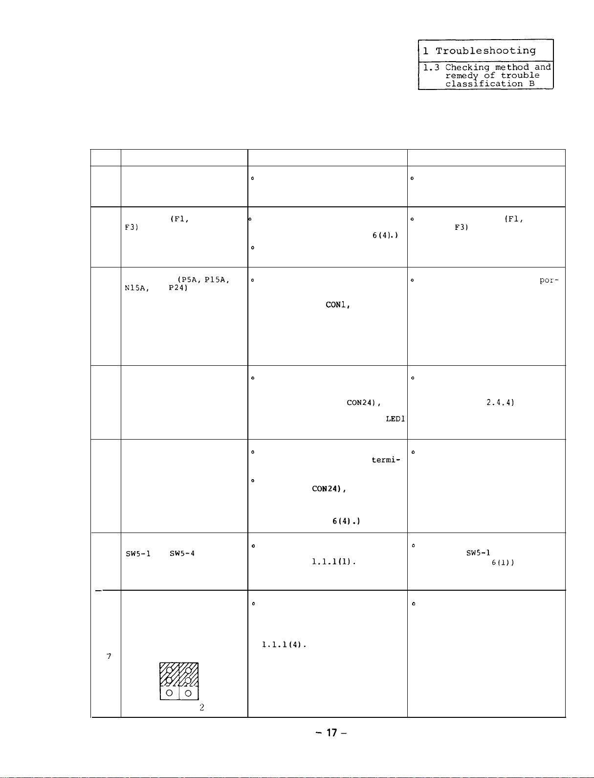
Checking method and remedy of trouble classification B
1.3.1 When the power is turned on,
tion panel does not appear at all.
the display of the opera-
Item Cause
The AC power is not
1
supplied.
The fuse
F3)
of the control power lamp LED1 on the SF-PW module
is blown.
2
The power
N15A,
the printed circuit outside of the SF-CA card in
board SF-CA card is the order of
shortcircuited.
3
The power supply inside0 Disconnect the connectors
the printed circuit
board SF-CA card is
4
shortcircuited.
or
(Fl,
F2, and/or 0 Check that the indication
(PSA, PlSA,
P24)
outside
D
Check the input pins Xl, X2,o Supply the power.
and X3 of the amplifier using
a circuit tester.
lights.
o
Check the electric continuity
using the circuit tester.
0
Disconnect the connectors
which are connected to the
and so on by referencing
Appendixes 1-4 or 1-5, turn
on the power again, and then
check that the indication
lamp LED1 on the SF-PW module
lights.
which are connected between
the SF-CA card and SF-PW
module (CON21 to
on the power again, and check
that the indication lamp
lights.
Check
(See Appendix
CONl,
6(4)
CON3,
CON24),
Remedy
o
Replace the fuse
and/or
.)
turn (See Section
LED1
(See
o
Open the shortcircuited
tion of a circuit outside
the SF-CA card.
(See Appendix 1.2).
D
Replace the printed circuit
board SF-CA card with a new
one.
F3)
with a new one.
Section 2.1.)
(Fl,
2.4.4)
F2,
por-
o
The control power SF-PWo Check that 200 VAC power is
module is defective.
5
All the dip switches
~~5-1
to
Sw5-4
printed circuit board
6
are not placed in the
OFF position.
-
When the equipment is
not
linked with the NC
through the bus, the
setting pins PIN1 and attached setting pin list
PIN2 on the SF-CA card
are not placed as 1.1.1(4).
follows.
7
3
2
1
PIN I PIN
on the
2
supplied to the input
nals of the SF-PW module.
0
Disconnect the connectors
(CON21 to
the power again, and check
that the indication lamp
LED1 does not light.
(See Appendix
o
Check the switch position of
switch SW5 by referencing
Reference
0
Compare the positions of the
setting pins on the SF-CA
card with those on the
by referencing Reference
CON24),
6(4).)
1.1.1(l).
-
17-
termi-
turn on
Replace the control power
with a new one.
(See Section 2.4.1.)
o
Correctly set the dip
switches
(See Appendix
o
Correctly set the setting
pins.
SWS-1
to SWS-4.
6(l))
Page 23
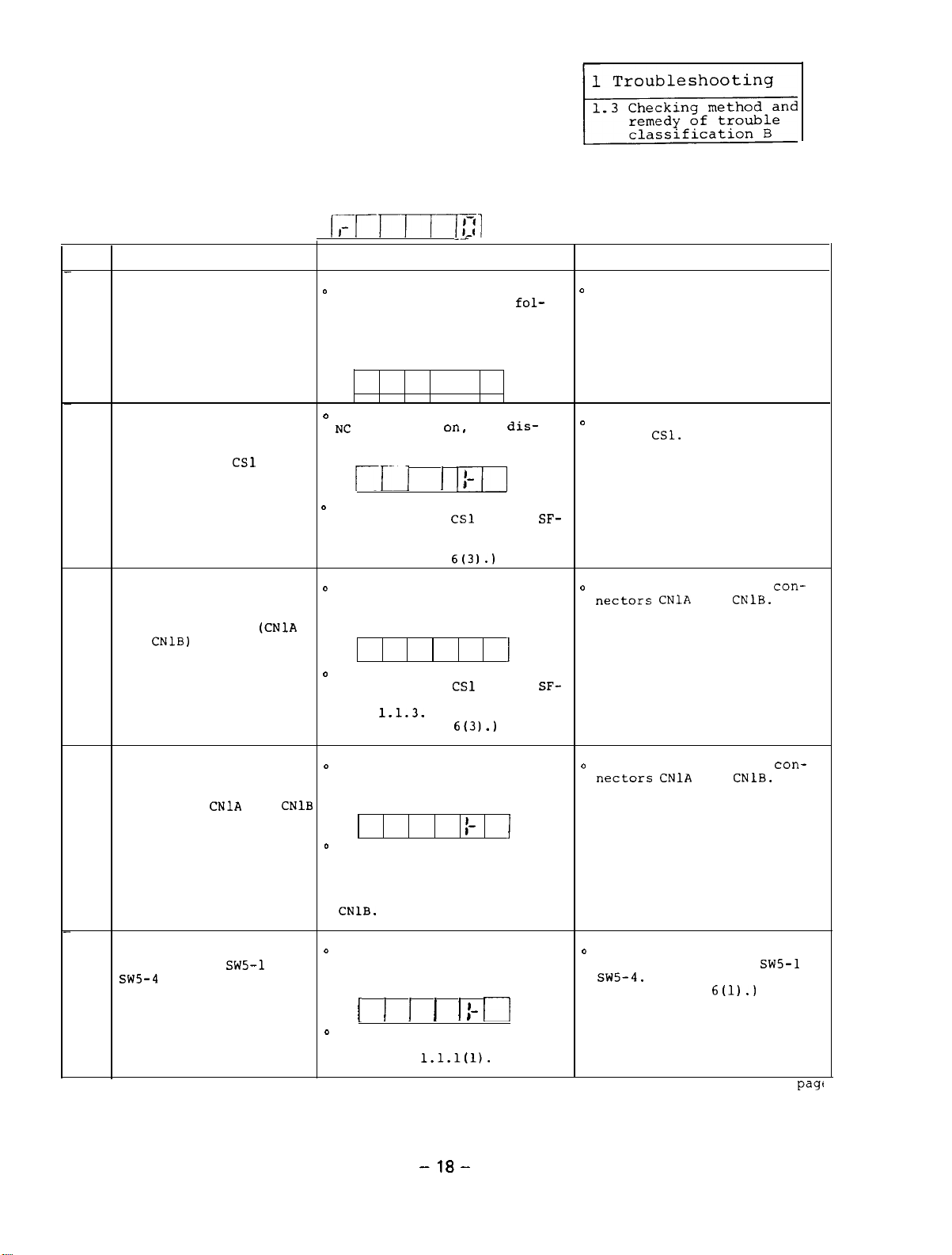
1.3.2 When the power is turned on,
tion panel does not indicate
display mode (as shown in the following figure).
the display on the opera-
the speed in the status
Item
When the equipment is
linked with the NC
through the bus, the
power of the NC is not
1
turned on.
When the equipment is
linked with the NC
through the bus, the
rotary switch
printed circuit board
2
SF-TL card is not placed
in the correct position.
When the equipment is
connected with the NC
through the bus, the bus
cable connectors
and
3
CNlB)
circuit board SF-TL card
are not correctly connected.
Cause
CSl
on the
on the printed
(CNlA
I,-r-rr-rTl
o
While the display on the
operation panel is as
lows,
and check that the display
indicates the speed (as shown
in the above figure).
Even after the power of the
' EC
play on the operation panel
turn on the NC power
is turned
is as follows.
Ill
o
Check the position of the
rotary switch
TL card by referencing Sec-
tion 3.1.3.
(See Appendix
o
Even after the power of the
NC is turned on, the display
on the operation panel is as
follows.
D
Check the position of the
rotary switch
TL card by referencing Reference
1.1.3.
(See Appendix
Check
--
I-
on,
the
I-
I
III
CSl
6t31.1
I-
CSl
6t31.1
fol-
dis-
on the
i
on the
SF-
SF-
Remedy
D
Turn on the power of the
NC.
D
Correctly set the rotary
switch
o
Correctly connect the
nectars CNlA
CSl.
and
con-
CNlB.
When the equipment is
linked with the NC
through the bus, the
connectors
on the printed circuit
board SF-TL card are nqt
4
correctly connected.
All the positions of the
dip switches
SW5-4
on the printed
circuit board SF-CA
card are not turned
5
off.
CNlA
SW5-1
and
to
o
Even after the power of the
N
C is turned on, the display
on the operation panel is as
CNlB
follows.
D
Check the connections by
referencing Appendixes l-6
to l-9.
that a termination resistor
is connected to the connector
CNlB.
Even after the power of the
0
NC is turned on, the display
on the operation panel is as
follows.
I
I I I
o
Check the positions of the
switch SW5 by referencing
Reference
Especially, check
I
1.1.1(l).
-18-
t
1-
II
o
Correctly connect the
nectars CNlA
I
o
Correctly set the positions
of the dip switches
sw5-4.
(See Appendix
Continued on the next
and
6(l).)
CNlB.
SWS-1
con-
to
page
Page 24
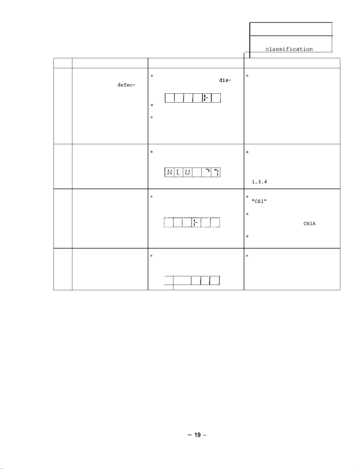
1 Troubleshooting
1.3 Checking method and
remedy of trouble
classification
B
Item
The printed circuit
board SF-CA card or
SF-TL card is
tive.
6
An alarm occurs.
7
The transmission of
parameters is required.
8
Cause
defec-
Check Remedy
o
0
Even after the power of the
NC is turned on, the
play on the operation panel
is as follows.
0
The above Items 1 to 5 cannot
0
Replace the printed circuit
0
Check that the display on
o
Even after the power of theo Check that the rotary switch
NC is turned on ,the display
on the operation panel is as
1 I I I I I
be applied.
boards SF-CA card and/or
SF-TL card with new ones and
check that the correct display appears.
the operation panel is as
follows.
:-::I_:
follows.
czfzlxi-_11
1-
-I
3
dis-
7
Replace the printed circuit
boards with the new ones.
0
Check the cause and take the
proper countermeasures by
referencing the description
relating to alarm display,
Section 1.3.3 (on display of
the amplifier) and Section
1.3.4
(On NC CRT).
"CSl"
on the SF-TL card is
placed in thecorrectposition
0
Check that the bus cable
CAM11 is securely connected
to the connector
SF-TL card.
o
Replace the SF-TL card with
a new one.
CNlA
on the
The equipment waits for
the IT start of the
servo amplifier. on the operation panel is as start up.
9
o
Even after the power of theD The amplifier of the servo
NC is turned on, the display
follows.
I-
I I I I
motor does not correctly
Check an alarm of
the servo amplifier.
- 19-
Page 25

1.3.3
An alarm appears on the display on the
board (SF-CA card) of the amplifier.
1-e
As an example:
,
8-1 ,_ c
, I-
,
3
printed circuit
Alternatively,
an alarm appears on the
NC CRT.
As an example: Spindle alarm 15 32
The contents of the alarm which appears on the spindle
amplifier are the same as those which appear on the NC
CRT.
The contents of alarms are listed in the following table.
The details of each alarm are described in the following.
(Note) If the alarm No.12
(MEl)
memory error 1 occurs,
it should be reset by turning off the power of
the spindle amplifier.
On the other hand, other alarm Nos. should be
reset by turning off the NC power.
-
20
-
Page 26
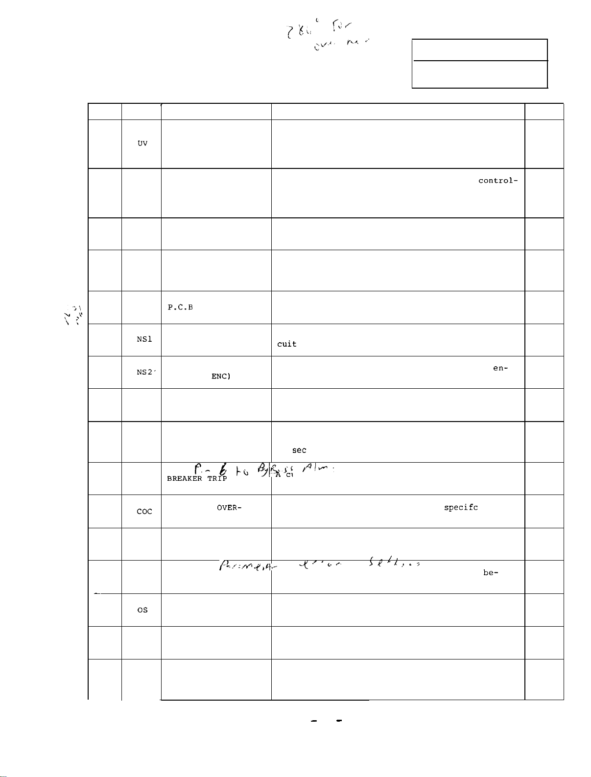
1 Troubleshooting
1.3 Checking method and
remedy of trouble
classification B
Alarm
No.
10
12
13
15
17
20
21
Abbr.
UV
ME1
ME2
BE
NSl
NSZ'
,
UNDER VOLTAGE
MEMORY ERROR 1
EXTERNAL CLOCK
ERROR
MEMORY ERROR 2
P.C.B
IC MAC007 ERROR
NO SIGNAL 2
(SPINDLE
Name
ERROR
ENS)
Description
The input power voltage drops to a value less
than the specification assured value or an
instantaneous power failure occurs for 15 ms or
more.
The internal memory for controlling the
ler is not correclty read and written.
(It is checked when the power of the controller
is turned on.)
The system clock which is sent from the NC is
defective.
The 2-port memory for communication which is
used for linkage with the M300 series CNC through
the bus does not correctly work.
Any part on the controlling printed circuit
board does not correctly work.
The part ICMACOO7 on the controlling printed cir-
cuit
board does not correctly work.
A signal is not input from the orientation
coder or the signal is not in the correct level.
control-
en-
Motion
(Note)
A
A
A
A
A
A
A
22
23
24
25
26
NSS IC MAC012 ERROR
OSE
BRT
cot
PL
SPEED CONTROL ERROR
EXCESS
B,,,L-,,&
CONVERTER
CURRENT flows in the converter.
POWER PHASE LACK
OVER-
j-a +%$I
4 / ; .,,4 .y
27
-
31
32
33
CPUE
OS
oc
ov
CPU ERROR
(DIVISION ERROR)
OVERSPEED
INVERTER OVERCURRENT
OVER VOLTAGE
'
The part IC MAC012 on the controlling printed
circuit board does not correctly works.
The difference between the referenced speed and
motor speed is 50 rpm or more and it takes for
12
set
or more.
fli@-
current which exceeds the specific value flows
in the main circuit.
An overcurrent which exceeds the
One or more of 3 phases is missed in 3-phase
power.
,‘.,_
-< .’ ‘ c- (’
A division error occurs in CPU operation
cause of incorrect parameters being set.
The motor speed exceeds 115% of the maximum speed
An overcurrent which exceeds the specific value
flows in the controller.
The voltage of the main circuit condenser exceeds
the specific value because of regenerative energy
in motor deceleration state.
I.
>i/ ‘I
/,
,, I
;
specifc
Continued on the next page.
value
be-
A
A
A
A
A
A
A
A
A
-
21 -
Page 27
Alarm
uo.
34
35
Abbr.
DP
DE
Name
DATA PARITY
DATA ERROR
Description
Parity error occurs in bus linkage with the M300
series CNC.
In bus linkage with the M300 series CNC, the
shift command which exceeds the specific value
is issued from the CNC.
Pl"CJ."ll
(Note)
A
A
36
46
52
57
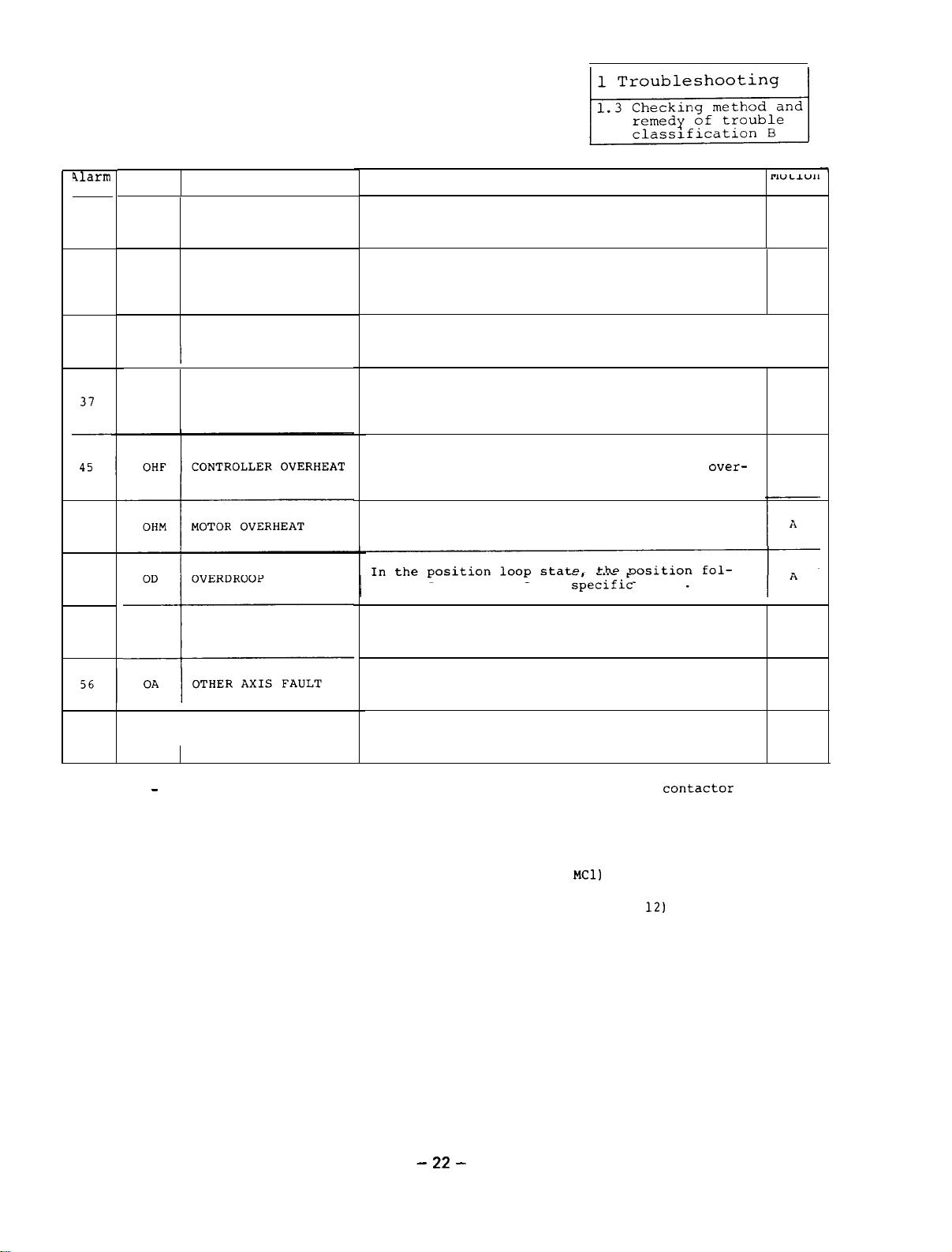
Motion A - The base shut-off occurs in the controller, the main circuit
TE
PE
OPE
TRANSFER ERROR
PARAMETER ERROR
OPTION CARD ERROR
turned off,
trouble signal contacts FA-FC are open.
and the motor stops in the free-run state.
In the bus linkage with the M300 series CNC,
data is not correctly transferred.
A parameter value which exceeds the allowable
range is set.
the controller is turned on.)
The ambient temperature is abnormal or the main
circuit devices are overheated because an
load is applied or the air cooling fan stops.
The motor is overheated because an overload
is applied or the motor cooling blower stops.
lowing error exceeds the
In the bus linkage with the M300 series CNC,
any fault occurs in an other servo axis.
Any function which is not provided with the
option card is selected.
(It is set when the power of
sbecific
value.
COntaCtor
In additon, the
over-
is
A
A
A
A
A
(Note)
For the main circuit contactor
For the trouble signal contacts FA and FC :
: See Appendixes l-4 and l-5
- 22 -
(contact
See Appendixes l-4 and 1-5
(CON1 pins 11 and
MC11
12)
Page 28
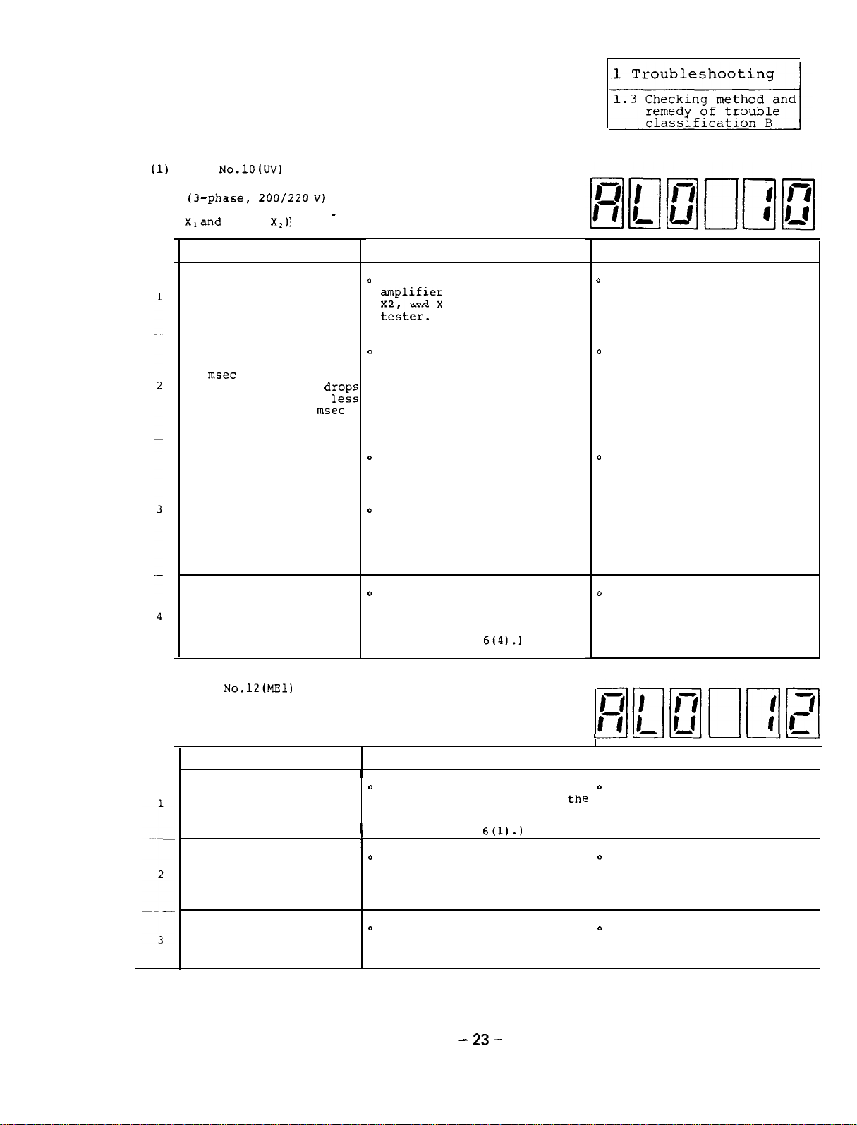
(1)
Alarm
No.lO(UV)
Under Voltage
[The voltage drop of the input voltage
(3-phase,
ZOO/220 V)
to the amplifier
is detected. (Voltage between phase
Xland
phase
X,)1
_
Item
Cause Check
The AC input votlage of
the amplifier drops to
a voltage which is less
than 170 V.
An instantaneous power
failure which lasts for
15
msec
(the input votlage
to a value which is
than 170 V for 15
or more occurs
drop2
less
msec
or more).
The power capacity is
insufficient.
The control power
(SF-PW module) is defec-
tive.
0
Check the voltage at the
;plifier
input terminals Xl,
and X3 using a circuit
teiter.
0
Check the voltage waveforms
at the amplifier input terminals Xl, X2, and X3 using an
oscilloscope.
0
Check the voltage waveforms
at the amplifier input terminals Xl, X2, and X3 using an
oscilloscope.
0
Check that the input voltage
drops while the spindle
motor is in the acceleration/
deceleration state or while
an overload is applied.
0
Check that the voltage bet-
ween ACDOW and DO24 of the
block A in the SF-PW module
is + 5V.
(See Appendix
6(4).)
Remedy
0
Check the cause of which the
input voltage drops and take
proper countermeasures.
0
Check the cause of the
instantaneous power failure
and take porper counter-
measures.
o
Increase the power capacity.
o
Replace the SF-PW module
with a new one.
(2) Alarm
No.l20l!Zll
Memory Error 1
[The integrify of the contents Of
RO
M are compared with those of RAM
during initialization.]
Item Cause
Check
I
EPROM is not installed
in the correct position.
0
Visually check that ROM's 1,
2, and 3 are installed at
correct positions on SF-CA
card.
1
(See Appendix
I
0
There is an imperfect
connection between pins
of EPROM and the socket.
Visually check that pins of
ROM's 1, 2, and 3 are not
bent and they are correctly
inserted into the sockets.
The printed circuit
board SF-CA card is
0
Replace the SF-CA card with
a new one and check that the
defective. new one correctly works.
- 23 -
6(l).)
-II-II-II
Remedy
o
Install each ROM in the cor-
rect position.
e
thl
D
Straighten the pins being
bent and securely insert
them into the socket.
o
Replace the SF-CA card with
the new one.
(See Section 2.4.4).
Page 29
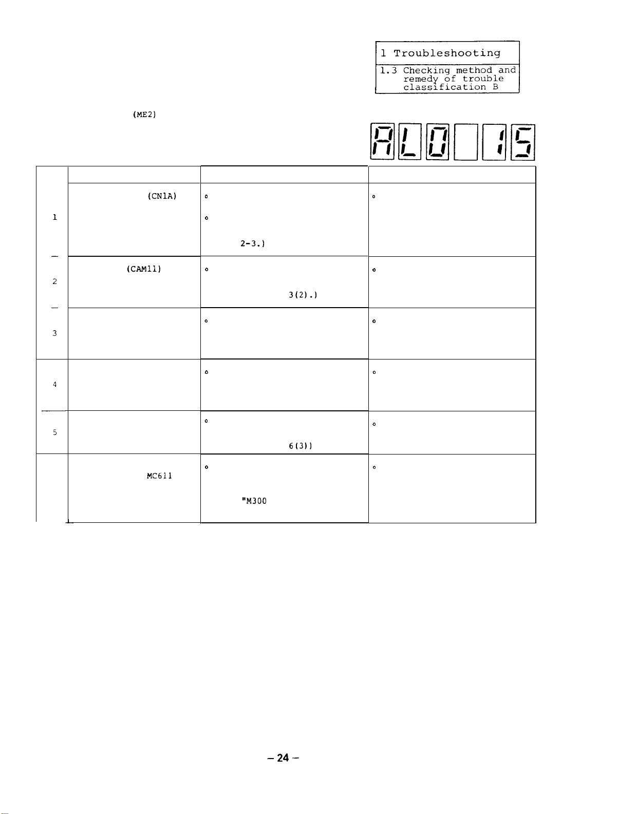
(3) Alarm No.15
(ME2)
Memory Error 2
[The integrity of the contents of
the 2-port RAM which communicates
with the NC during initialization
is checked.1
Item
The connector
which is linked with the
NC through the bus is
not securely connected.
Cause Check Remedy
D
(CNlA)
Check the looseness of the
connector.
o
Check that the set screws of
the connector are not loosen.
(See Appendixes l-6 to l-9
and
2-3.)
The cable
is connected with the NC
(CAM11)
which0 Replace the cable with a new
one and check that the equip-
through the bus is ment correctly works.
defective.
(See Appendix
The ground wires of theo Visually check that the
amplifier, and motor
NC,
are not correctly con- connected by referencing
nected.
The signal cable is not
correclty shielded.
ground wires are correctly
Appendix 1.
0
Visually check that the
signal cable is correctly
shielded by referencing
Appendix 1.
o
The printed circuit
board SF-TL card is
defective_
The NC side printed
circuit board
MC632 is defective.
6
~~611
or
Replace the SF-TL card with
a new one and check that the
equipment correctly works.
(See Appendix
o
Replace the MC611 or MC632
cards with new ones and check
that the equipment correctly
work.
(See
"M300
Series Maintenance
Manual".)
L
3(2).)
6(3)1
D
Securely connect the connec-
tor and tighten the screws.
o
Replace the cable with the
new one.
o
Correclty connect the
ground wires.
o
Correctly shield the signal
cable.
o
Replace the SF-TL card with
a new one.
(See Section 2.4.3.)
D
Replace the MC611 or UC632
cards with the new ones.
MC632: M310
MC611: All other
- 24 -
Page 30
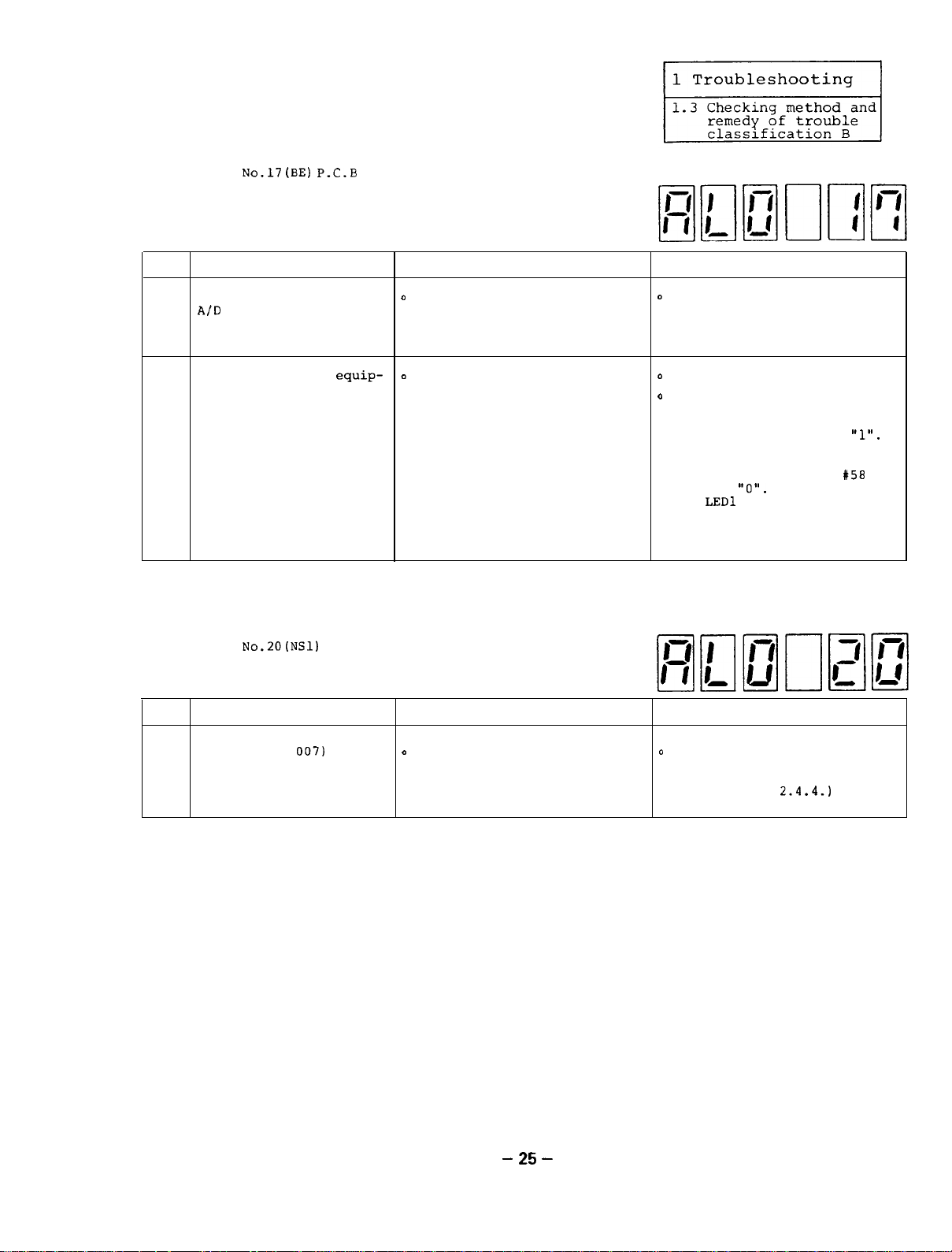
(4) Alarm
[Whether a component (especially
A/D converter) on the printed circuit board is normal or abnormal
is checked.
No.l7(BE) P.C.B
1
error
Item
A component (especially,
A/D
1
2
(5) Alarm
Item
converter) on the
printed circuit board
SF-CA card is defective. works.
The power of the
ment is turned on while
the NF in the unit is
turned off.
[The internal codes of the IC MAC007
on the SF-CA card are checked.]
Cause Check Remedy
equip-
No.20(NSl)
IC MAC007 Error
Cause Check
D
Replace the SF-CA card with
the new one and check that
the equipment correctly
D
Check that the NF is turned
off.
o
Replace the SF-CA card with
the new one.
(See Section 2.4.4.)
o
Turn on the NF.
o
To check only the control
circuit without appearance
of alarm No.17, set the
parameter X58 CVHS to
However,
the normal operation mode,
make sure to set the
CVHS to
the
ing regeneration) on the
SF-CA card continuously
lights.
to return back to
"0".
LED1
(which lights dur-
Otherwise,
Remedy
"1".
158
The IC (MAC
printed circuit board
1
SF-CA card does not
correctly work.
007)
on the
o
D
Replace the SF-CA card with a
new one and check that the board SF-CA card with the
equipment correctly works. new one.
Replace the printed circuit
(See Section
2.4.4.)
- 25 -
Page 31

1 Troubleshooting
1.3
Checking method and
remedy of trouble
r
classification B
(6) Alarm
[The signals of
Item Cause Check
1
2
NO.~~(NS~)
spindle orientation encoder are checked
during orientation and synchronous tapping
state.1
The cable
the spindle orientation
encoder is defective. oscilloscope. (See Appendix 3
The encoder for the
spindle orientation is same manner as Item 1 above. new one.
defective.
NO Signal 2 (Spindle
phases
(MR-ZOLF)
A, B, and C of the
toD Observe the signal waveform
from the encoder using an
o
Check the check pins on the
printed circuit board SF-TL
card.
.
Between
.
Between CH2 and DGA, for
.
Between CH3 and DGA, for
(See Appendixes
o
Replace the cable with a new
one and check that the equipment correctly works.
(See Appendix 1 - 7.)
o
Check the wave form in the
o
Replace the encoder with a
new one and check that the
equipment correctly works.
(See Appendix 7.)
phase A
phase B
phase
9(3).)
ENC)
CHl
and DGA, for
2
6(3)
and
Remedy
o
Replace the cable to the
encoder with the new one.
(2j.l
*
D
Replace the encoder with the
The printed circuit
board SF-TL card is from the encoder at CONB
defective.
3
The 5V power is not
supplied from the NC NC side.
side to the encoder.
4
o
Observe the signal waveform
on the SF-TL card using the
oscilloscope and check that
it is normal.
(See Appendix 1 -
o
Check the 5V power on the
o
Replace the cable with a new
one and check that the
ment correctly works.
7.1
equip-
o
Replace the printed circuit
board SF-TL card with a
new one.
(See Section
o
Repair the power supply on
the NC side.
Refer to M300 series
Maintenance
o
Replace the cable with a new
one.
o
If the 5 V power is not
plied from the NC side
(namely,
connected with the NC),
shortcircuit the pin 5 on
the SF-TL card to pins 2 and
3 (no power supply form the
NC).
2.4.3.)
manual
sup-
when CONAA is not
- 26 -
Page 32

(Note) The correct output waveform of the encoder is as follows:
@
When the spindle of the machine rotates counterclockwise at approx. 500 rpm
while the bit 8 of the parameter
Phase A
ORSZ
is 0:
Phase
Phase
@
When the spindle of the machine rotates clockwise at approx. 500 rpm and when
the bit 8 of the parameter OSR2 is 0,
occurs.
(7) Alarm
[The internal codes of the IC MAC012
Item Cause Check Remedy
1
No.22(NSS)
are checked. 1
The IC (MAC 012) and
the related circuits on
the printed circuit
board SF-CA card do
not correctly work.
B
2
___.
IC MAC012 Error
I
o
Replace the SF-CA card with ao Replace the printed circuit
new one and check that the board SF-CA card with the
equipment correctly works.
(See Appendix
the same waveform as the above figure
new one.
6(l))
(See Section 2.4.4.)
- 27 -
Page 33

>‘I / c
4
,P+
(13) Alarm
[The difference between the speed reference
4
No.23(OSE)
value and real speed is checked and if the
deviation which is 50 rpm or more lasts
for 12 sec. or more, an alarm occurs.1
c
Speed Control Error Excess
/)
0
ir
Item
The phase sequence of
wires U, V,
are connected between
the amplifier and the
motor is incorrect.
One of the wires U, V,
and W which are
netted
amplifier and the motor
is broken.
The motor is overloaded.
The printed circuit
board SF-CA card is
defective.
The integration gain
parameter VKI (amplifier
parameter X37; NC
meter:
loop is set to 0.
Cause
and W which
between the
#23)
of the speed
con-
para-
Check
o
Increase the reference speedD Correctly connect the wires
and check that the motor
rotates at a low speed.
o
Visually check the phase
sequence of wires U. V,
and W.
o
Check that the motor does not
smoothly rotate.
o
Remove the wires U, V, and W
on the amplifier side and
check that there is no electric discontinuity in the
wires U, V, and W.
o
Check whether the motor iso Review the cutting condition
overloaded using a load meter
or load display in the status
display mode.
(See Section 1.1.1)
D
Replace the SF-CA card with ao Replace the printed circuit
new one and check that the board SF-CA card with the
equipment correctly works.
D
Check the parameters beingo Set the parameters to the
set by referencing Section
1.1.1
or 1.1.2.
U, V,
amplifier and the motor.
0
Replace the power wire which
is broken with a
and tool being used.
new one.
(See Chapter 2.)
standard values by refer-
encing Reference 1.2.2 or
1.2.3.
0
If the motor unstably
rotates,
to correct values by refer-
encing Alarm No. 31 Item 2.
Remedy
and W between the
new one.
set the parameters
The volume on the
printed circuit board
for the motor built-in
encoder (in the motor
terminal box) is not
correctly adjusted.
o
Check that the motor rotates
at several
speed display is
o
Set the parameters of the
amplifier as follows and
put the speed reference and
start command to rotate the
motor at a low speed.
parameter 00 becomes valid
just after it is set to
Since the parameter is
cleared when the power is
turned off or reset, after
it is set to
speed reference and start
command.
ten
rpm and the
"0".
"l",
input the
in-
The
"ll..
- 28 -
0
Adjust the volume
and VR4 so that the
VR3,
output waveforms of phases
A and B are in the
ard value range by referencing the section
ing to adjustment and
replacement of motor
built-in encoder (Section
6.9).
Continued on the next page.
VRl, VR2.
standrelat-
Page 34

1 Troubleshooting
1.3
Checking method and
remedy of trouble
classification 0
Item
The printed circuit
board in the motor
built-in encoder speed display indicates
(motor terminal box) is
defective.
7
Cause
Check Remedy
o
Check the signal waveform at
the check pins on the printed
circuit board SF-CA card
using an oscilloscope.
Phase A signal:
Phase B signal:
(See Appendixes
9(l).)
(Note) Before using the check
pins,
amplifier should have been
turned off.
0
Check that the motor rotates
at several ten rpm and the
o
Like the same manner as the
Item 6 above, in the open
loop state, rotate the motor
at a low speed.
0
Like the same manner as the
Item 6,
waveform of the check pins on
the SF-CA card using an
oscilloscope.
0
By referencing the descrip-
tion relating to adjustment
and replacement of the motor
built-in encoder described
in Section 2.9, observe the
waveforms between PA and PGA
and between PB and PGA using
an oscilloscope and check
that they can be in the
standard value range using
volume resistors
VR3 and
the power of the
check the signal
VR4).
CH44-CH9
(or AGA)
CH45-CH9
(or AGA)
6(l)
and
(VRl, VR2,
"0".
0
Replace the printed circuit
board in the motor terminal
box and adjust the controls
by referencing Section 2.9.
The sensor in the motoro Check that the output
built-in encoder is forms between PA and PGA and
defective.
a
(9)
(10)
Alarm
Alarm
No.24tBRT)
No_25(COC)
Breaker Trip
Converter Overcurrent
between PB and PGA on the
encoder printed circuit board
cannot be adjusted in the
standard value range even
after the printed circuit
board has been replaced in
the manner described in the
Item 7 above.
- 29 -
wave-
o
Replace the entire motor
with a new one.
o
If the motor cannot be
replaced, replace it
together with the sensor
and printed circuit board
by referencing Section
2.9.
Page 35

(111
Alarm
No.32(OC)
Inverter Overcurrent
Item Cause
The input power voltage
waveform is defective.
1
Check
o
Observe the voltage waveforms
at the input terminals Xl, X2,
and X3 of the amplifier using
an oscilloscope.
0
Check that the voltage wave-
forms are as follows even in
the acceleration or
tion state.
(al
If the waveform is
tially lost:
It should be
If the peak value drops:
(bl
t.-
100 us or less.
<-.
decelera-
par-
-L
It should be
2 to 3% or
less.
Remedy
Increase the power capacity.
0
0
Thicken the size of the
cable between the input
power supply and amplifier.
0
Check other semiconductor
devices which generate
distorted waveforms and
install surge killers and
so force.
(For example, MATSUO made,
rating 200 VAC,
12003-5041, etc.)
DCRZ-
The input power
ante
is high.
(Example,
that two transformers
2
are connected in series
or a variable
transformer is con-
netted)
The input power
quency remarkably
3
changes.
The motor selection
parameters
4
are not correctly set.
The transistor module
is defective.
5
in the cases
#Ol
imped-
auto-
fre-
and
102
0
o
Check that the alarm occurs
only when the motor speed
decelerates from a high
speed.
0
Check that the input voltage
temporarily drops to 170 V power supply and amplifier.
or less when the motor
decelerates.
0
Check the voltage frequencies
at the input terminals Xl,
and X3 of the amplifier
x2,
using a frequency counter.
o
Check that the parameters are0 Correctly set the
correctly set by referencing
Reference 1.2.2.
0
Check that this alarm occurs
even after the equipment is unit of the amplifier with
reset.
0
Disconnect the cable between
the amplifier and motor and
check that this alarm occurs
when only the amplifier is
operated.
(See Appendix l-2.1
-
30
-
Replace the power supply
with an other one whose
power impedance is low.
0
Tighten the screws of
nections
0
Check the cause of the fre-
quency
the related controls so
that it is in the specification range.
meters.
(See Reference
0
Replace the main circuit
a new one.
between the input
variation and
1.2.3.)
Continued on the next page.
con-
adlust
para-
Page 36

1 Troubleshooting
1.3 Checking method and
remedy of trouble
classification B
Cause
The diode stack is
defective.
The surge absorbers and
condensers are defective.
The current detection
circuit is defective.
8
The motor is overloaded.
9
Check
o
Check the diode stack in the
same manner as the Item 5
above.
o
Check them in the same manner
as the Item 5 above.
0
Observe the waveforms at the
following check pins using an
oscilloscope and check that
the peak value exceeds 10 V.
Between CH39 and AGA:
Regenerative converter
side
Between CH42 and AGA:
Converter side
Between CH43 and AGA:
Inverter side
(See Appendix
0
Check that the motor is over-
loaded using a load meter or
the load display in the
status display
Section
1.1.1).
9(l).)
mode (see
Remedy
0
Replace the main circuit
unit of the amplifier with
a new one.
(Note)
See Section 2.6 and
2.7.
0
Replace the main circuit
unit of the amplifier with
a new one.
0
Replace the printed circuit
board SF-CA card with a new
one.
(See Section 2.4.4.)
(Note) Normally, the peak
voltage is in the range
from 6 to 7 V while the
motor accelerates or
decelerates.
D
Review the cutting condition
and tool being used.
The cable connections
between the amplifier
and motor are incorrect.
10
The wiring of the motor
is rare-shortcircuited
or earth-grounded.
11
3
Visually check the cable con-
nections.
0
Check that the screws of the
cable connection terminal are
loosen.
Disconnect the cables between
the amplifier and motor and
check the insulation resistance between the following
leads.
Between U and W; between V
and W; between U and W;
between each of U, V, and
W and E
3
Correctly connect the
cables.
s
Tighten the screws being
loosen.
)
Replace the motor with a
new one.
-
31
-
Page 37

1 Troubleshooting
1.3 Checking method and
remedy of trouble
classification
B
(12) Alarm
Item
1
2
(13) Alarm
Item
1
No.26(PL)
[When R and T of phases R, S, and T are
normal,
checked.]
One of phases R, S, and
T is lacked when the
power is turned on.
One of the fuses
and F3 has been blown
when the power is turned
on.
No.27(CPUE)
[This alarm occurs when an CPU operation where
a value is divided by 0 is executed or the
result of division is overflowed.)
The parameter relating
to gear ratio is
correctly set.
Power Phase Lack
whether there is phase S is
Cause
D
Check the voltage between any
two phases of R, S, and T at
the input power terminals
and X3 using a circuit
X2,
tester.
o
Check the electric continuity
of each fuse using the
cuit
tester.
D
Check the parameter by
encing
Reference 1.2.2 for
that which is set from the
amplifier and Reference 1.2.3
for that which is set from
the NC.
Cause
Fl,
F2,
CPU Error (Division error)
in-
Check
Check
Sl,
cir-
refer-
Remedy
o
Check the cause of the phase
lack and take proper
countermeasures.
Replace the fuse being blown
0
with a new one.
(See Section 2.1.)
Remedy
o
Correctly set the parameter.
(Note) Compare the parameter
in the parameter list on
the cover of the amplifier
with that being set.
(See Appendix 10)
The connector
which is linked with the
2
NC through the bus is
loose.
The cable
is linked with the NC
3
through the bus is
defective.
The following parameterso Check the parameters by
relating to the gain of
the speed loop are
4
correct.
When a special motor iso Compare the
used (when
5
are set), the motor
constants
incorrect.
(CNlA)
(CAMll)
VKP,VKI,ORSl.
181
whichD Check the cable in the same
in-
X01
and 02
to
XAF
are
o
Check the cable in the same
manner as the alarm No. 15
(k=2).
manner as the alarm No. 15
(-2).
referencing Reference 1.2.3.
the parameter list on the
amplifier cover with those
being set.
(See Appendix 10.)
parameters.in
- 32 -
o
Securely connect the
tor and the set screws.
o
Replace the cable with a new
one.
o
Correctly set the parameters.
(Note) Compare the parameters
in the parameter list on
the amplifier cover with
those being set.
(See Appendix 10.)
D
Correctly set the parameters
connec-
Page 38

1 Troubleshooting
I
1.3 Checking method and
remedy of trouble
classification
B
I
(14) Alarm
(The real speed of the motor is checked
Item Cause Check
1
No.31(0S)
and when it exceeds 115% of the motor
maximum speed,
The reference speed
exceeds 115% of the
maximum speed. speed being set.
The speed control system oObserve and check the signal
is unstable and an
shoot occurs.
Overspeed
this alarm occurs.)
o
Compare the reference speed
with the following maximum
Parameter being set from
the amplifier:
Parameter being set from
the NC: #17(TSP)
(See References
and
over-
between the speed signal
terminals SMO and OM using
an oscilloscope (See
dixes l-4 and l-5).
1.2.3(3).)
#31(TSP)
l-2.2(2)
Appen-
-~-
0
Decrease the reference
speed.
o
Correctly set the parameter
for motor maximum speed.
0
Decrease the parameter
values of the speed loop
gain VKP and VKI (amplifier
parameter
parameters
(Note) To check the occurrence
Remedy
Y36
and
#22
and X23).
--
#37
or NC
The motor built-in
coder is defective.
3
The printed circuit
board SF-CA card is
4
defective.
en-
o
If the signal output is
saturated when it exceeds
10 V because a too high speed
is set,
age rises to around 115% in
the speed mode of the status
display (see Section
or using the NC CRT monitor.
D
In the same manner as the
alarm
encoder output signal
form using the oscilloscope.
o
Rotate the motor using the
reference speed which is
slower than
and check that the frequencies of the signals of the
phase
following relation.
f(Bs) = +
o
Replace the SF-CA card with
a new one and check that it
correctly
check that the
1.1.1)
No_23(OSE),
A or B satisfy the
works.
check the
the
middle speed
x
(motor
speed(rpm)
wave-
volt-
(b) If the alarm does not
occur,
decrease the parameter
values of VKP and VKI.
o
In the same manner as the
alarm
replace the motor built-in
encoder with a new one.
No.23(OSE),
adjust or
1
o
Replace the printed circuit
board with a new one.
(See
Section 2.4.4.)
!
-
33
-
Page 39

(15) Alarm
No.33(OV)
OVerVOltage
[The voltage in the converter circuit is
checked and if it exceeds 400 V, this alarm
occurs.)
Item
The input power voltage
Cause Check
0
In the same manner as the
waveform is abnormal.
1
0
The input power
ante
is high. alarm
imped-
In the same manner as the
2
o
An instantaneous power
In the same manner as the
failure occurs in the
input voltage or the input power.
3
voltage drops when the
motor decelerates.
alarm No.24, No.25, and
No.32, check the waveform.
check the input power.
alarm
No.24/NoW25/No.32,
No.lO(LJV),
check the
Remedy
0
See the alarm
No.24/No.25/
No.32.
0
Increase the power capacity.
0
Thicken the size of the
cable between the input
power supply and the ampli-
fier.
0
Improve other components
which generate distorted
waves by installing surge
killers and so forth.
0
See the alarm
No.24/No.25/
No.32.
0
Replase the power supply
with that whose impedance
is low.
o
Tighten the screws of the
cable connections between
the input power and amplifier.
o
See the alarm
o
Check the cause of the
No.lO(UV).
instantaneous power failure
or voltage drop and improve
the power condition.
The printed circuit
board SF-CA card is
4
defective.
0
Replace the SF-CA card witho Replace the printed circuit
a new one and check that the board SF-CA card with a
equipment correctly works.
The main circuit unit0 Check the regenerative
is defective.
5
transistor module by
encing
Section 2.5.
- 34 -
refer-
new one.
(See Section 2.4.4.)
o
Replace the amplifier main
circuit unit with a new
one.
(Note) See Section 2.7.
Page 40

(16)
Alarm
No.13() External Clock Error
[This alarm occurs when the system clock
which is sent from the NC is defective.]
(17)
Alarm
No.34(DPl
Data Parity
[The parity of the data
whick
is trans-
mitted from the NC is checked.]
(18)
Alarm
No.35(DE)
Data Error
[This alarm occurs when the position refer-
ence of the synchronous tap which is
transmitted from the NC is too large.]
(19)
Alarm
No.36(TE)
Transfer Error
[This alarm occurs when data from the NC
is not completed.]
Item Cause
The connector
which is linked with the
1
NC through the bus is
(CNlA)
0
In the same manner as the
alarm
connector.
Check
No.l5(ME2),
loosed.
The cable
is linked with the NC
2
through the bus is
(CAM111
which
o
In the same manner as the
alarm
No.lS(ME21,
connector.
defective.
The NC,
3
motor are not correctly alarm
amplifier, and
o
In the same manner as the
No.l5(ME2),
grounded. grounding.
The signal cable is not
correctly shielded.
4
o
In the same manner as the
alarm
No.lS(ME21,
shielding of the signal
cable.
The termination resistor o Check that the termination
of the bus connection is
abnormal.
resistor is correctly
installed.
(See Appendixes 1-6 to l-9.)
5
0
Replace the termination
resistor with a new one and
check that the equipment
correctly works.
check the
check the
check the
check the
Remedy
0
Tighten the connector and
mounting screws.
o
Replace the cable with a
new one.
a
Correctly ground them.
o
Correctly sheild the signal
cable.
D
Replace the termination
resistor.
(See Appendix
3t21.1
The bus interface
cuit
6
of the printed
cuit
board SF-TL card is
defective.
cir-
cir-
o
Replace the SF-TL card with a 0Replace the printed circuit
new one and check that the board SF-TL card with a
equipment correctly works. new one.
(See Section 2.4.3.)
on
- 35 -
Page 41

Item
The bus interface
cuit
cuit
card on the NC side is
defective.
A travel command which
exceeds the specification value is issued
from the program.
8
(20)
Alarm
(This alarm occurs when a parameter which
exceeds the allowable range is set.1
Cause
of the printed
board M?611/MC632
No.37(PE)
cir-
cir-
Parameter Error
o
Replace the
with a new one and check that
the equipment correctly works
o
Check that the spindle speed
reference exceeds
6192
(Parameter
GRA
Check
MC6ll/MC632
xlOr
GRA
= number of gear teeth
(rpm)
on spindle side)
card
.
Remedy
0
Replace the
card with a new one.
I
o
Correct the program.
MC611/MC632
I
Item
1
Cause Check
1
A parameter which
exceeds the allowable
range is set.
I I
o
Check that the parameter be-
ing set accords with that in
the parameter list by refer-
encing Reference 1.2.2 for
the parameter being set from
the amplifier and Reference
1.2.3 for that
the NC.
beinu
set from
Remedy
o
Correctly set the parameter
value.
-
36
-
Page 42

“.4
P
(21)
Alarm
No.45(OHF)
[This alarm occurs when the thermal protect
which is installed in the controller exceeds
the temperature being set.]
(Ambient temperature:
Fin temperature
Controller Overheat
:
6O='C
1OO~C'
-L
IL:
0
Item Cause
The fan which cools the
fin is defective. rotates.
1
The ambient temperature
of the amplifier is high.
2
The equipment is
loaded.
3
The thermal protector
(THSZ)
which is
led on the fin is
defective.
Alternatively, the
thermal
which detects the
ambient temperature of
4
the amplifier is defec-
tive.
THSl
ture = 60°C
(Ambient temperature)
THS2
ture =
(Fin temperature)
protector(THS1)
setting tempera-
setting tempera-
100°C
Check
o
Check that the fan normally0 Replace the cooling fan with
D
Measure the ambient
ature of the amplifier in the
high voltage panel.
over-o Check the load condition
instal-
ing a load meter or the load
display (see Section
in the status display mode.
o
Check that
frequently started and
stopped.
o
Check that electricity
does not flow between the
ends of the thermal protector by referencing Appendix
"Main circuit block
4,
gramn
"Spindle amplifier component
layout".
(Note) Separately check
the
and Appendix 5,
and
THSZ.
temper-
.
1.1.1)
equipment is
THSl
us-
dia-
Remedy
a new one.
(See Section 2.3.)
o
Unless the cooling unit in
the high voltage panel
rectly
works, replace it
with a new one.
o
If the ambient temperature
exceeds
the cooling power.
D
Review the cutting condition
and tool.
o
Decrease the frequency of
start and stop operations.
o
Replace the thermal protec-
tor
(See Section 2.2.)
THSl
55'C,
strengthen
or
THSZ.
cor-
The alarm detection
cuit
5
6
in the printed
cuit
board SF-CA card is
defective.
The cooling fan is dirty
by dust and the cooling
effect is degraded.
o
Replace the SF-CA card with
circir-
a new one and check that
the equipment correctly
works.
visually or by touching the
0
cooling fan, check the
degree of dirt.
- 37 -
o
Replace the printed circuit
board SF-CA card with a
new one.
(See Section
o
Clean the cooling fan using
a factory utility air or
vacuum cleaner.
2.4.4.)
Page 43

1
I
1.3
Checking method and
remedy of trouble
classification
B
(22) Alarm
[This
Item
1
No_46(OHM)
alarm
tor which is installed in the motor exceeds
the temperature being set
The motor cooling fan
defective.
The motor cooling systen
is dirty.
Check that the air in-
take portion of the
motor cooling fan is
clogged with foreign
matter or machine com-
ponents.
The motor is overloaded.
occurs when the thermal protec-
Cause
Motor Overheat
(145"Cl.l
o
Visually check that the fan
is
motor normally rotates.
0
Visually or by touching the
cooling system, check the
degree of dirt.
o
Visually check the position
of the foreign matter or
components.
0
Check the load of the motor
using a load meter or the
load display in the status
display mode
1.1.1).
0
Check that the motor is fre-
quently started and stopped.
Check
(see Section
Remedy
3
Replace the motor cooling
fan with a new one.
(See Section 2.8.)
D
Clean the cooling system
using the factory utility
air or vacuum cleaner.
D
Remove the foreign matter.
D
Change the position of the
machine components.
D
Review the cutting condition
and tool.
D Decreas
start and stop operations.
the frequency of the
The motor built-in
thermal protector is
defective.
The following cable connections are defective.
Motor Amplifier
side
OHS1 -
OHS2 - CON2 pin 2
side
CON2 pin 3
I
o
After stopping the motor and
turning the cooling fan to
fully cool the motor, check
that the motor leads
OHS2 is shortcircuited.
(When they are shortcircuited
the thermal protector is
normal.)
o
Check the wire breakage or
connector imperfect contact
using a circuit tester.
OHS1
and
D
Shortcircuit
of CON2 on the amplifier
side as a temporary repair
and continue the operation.
(See Appendixes l-4 and
D
At a convenient time, re-
place the motor with a new
one.
D
Replace the signal cable
with a new one.
D
Repair the connector's
imperfect contact or replace the connector with a
new one.
OHS1
and OHS2
l-5)
- 38 -
Page 44

(23) Alarm
[This alarm occurs when the position error
N0.52(0D)
becomes too large in synchronous tapping mode
(for 8 rotations against the reference value.)]
Over
Droop
Item
The parameter
which is set from the
1
amplifier is not
rectly set.
The bits 8 and E of the
parameter ORS2
2
amplifier;
NC) are not correctly
set.
The orientation encoder
is defective.
3
The reference time
constant is small.
4
Cause
#16(~~)
#03 (PLG)
cor-
(#30
for
for
Check Remedy
D
Check the parameter being set
by referencing Reference
1.2.2(2).
D
Check the parameter being set
by referencing Reference
1.2.2 (2) and
0
In the same manner as the
alarm
signal waveform from the encoder.
0
Measure the acceleration time o
using a stop watch or observe acceleration time constant
the speed signal terminals parameter CSN (amplifier
SMO and OM using an
scope and check that the
acceleration time is shorter
than the reference constant
time.
No.21(NS2),
(See Appendixes 1-4 and l-5.)
1.2.3(3).
check the
oscillo-
o
Correctly set the parameter
value.
o
Correctly set the parameter
values.
0
Replace the encoder with a
new one.
Increas
parameter
meter
the value of the
#33
#19(PR)).
or NC
para-
(24)
Alarm
Item
1
2
3
4
No,56(OA)
The servo axis alarm
occurs.
The cable CAM11 whicho Replace the cable CAM11 and
is linked with the NC
through the bus is rectly works.
defective.
The connectors
CNlB)
on the printed
circuit board SF-TL card
are not correctly
netted.
The termination resistor
is defective.
Other Axis Fault
Cause
(CNlA
and
con-
Check
o
Check that the servo axis
alarm occurs.
check that the equipment
(See Appendix
o
Visually check the following
connections.
CNlA -
CAM11 cable
CNlB -
termination resistor
0
Check that the connector
screws are loosen.
o
Replace the termination
resistor which is connected
to the connector
check that the equipment correctly works.
(See Appendix
3(2).)
3(2).)
CNlB
and
Remedy
o
Remove the cause of the
servo axis alarm.
0
Replace the cable CAM11 with
cor-
the new one.
o
Correctly connect the CAM11
cable and termination
tor in place.
0
Tighten the connector screws
0
Replace the termination
resistor with a new one.
resis-
39 -
Page 45

(25) Alarm
Item
1
No.57(OPE)
The option card does
not conform with the
specification.
Option Card Error
Cause Check
D
Check that the order list
conforms with the option card
name.
----~-
Remedy
D
Check the specification.
.
- 40 -
Page 46

1 Troubleshooting
1.3.4
Item
Trouble analysis
1
The control signal cable o Check that the cables are
or power cable is
2
correctly connected or
is broken.
The input power voltageo Measure the voltages at theD Improve the power condition
is abnormal.
3
The control power supplyD Measure all the DC output
(SF-PW module) is
4
tive.
The motor does not rotate.
Cause Check
0
in-
defec-
When a rotation command iso Review the cause and take a
issued,
on the display on the spindle
amplifier printed circuit
board (SF-CA card).
D
When no alarm occurs:
correctly connected and
they are not broken.
input terminals Xl, X2, and so that the input power
X3 of the amplifier using a voltage is in the allowable
circuit tester.
(See Table 1.3.)
voltages of the SF-PW module
using a circuit tester.
(See Appendix
an alarm is indicated
6(4).)
Remedy
proper action by referencing
Section 1.3.3.
0
Go to the Item 2 or later.
0
Correctly connect them.
D
Replace the broken cable
with a new one.
range.
o
Replace the control power
supply (SF-PW module) with
a new one.
(See Section 2.4.1.)
o
The printed circuit
board SF-CA card is as follows,
defective.
5
The external emergency
stop signal or reset
signal is input.
6
(Note)
The parameter 00 becomes valid just after it is set to 1. Since the parameter is
cleared when the power is turned off or the equipment is reset, just after 1 is set,
input the speed reference and start
Set the amplifier parameterer
o
Check that the bit 2
input a reference
amnrrnn
speed in the open loop state
to cause the motor to rotate,
and check that a reference
sine wave occurs on the
oscilloscope.
l%z;:%AGA
CH14 - AGA
(See Appen-)
dix 9(l).
(emergency stop) of the
external signal is turned on
or the portion between CON1
pins No.47 and No.48 (emergency stop) or portion between pins No.19 and No.20
(alarm reset) is turned on.
U-L
e
coannand.
(Note)
o
Replace the printed circuit
board SF-CA card with a new
one.
(See Section 2.4.4.)
0
Correctly connect the
nal signal cable.
exter-
-41-
Page 47

Cause
The
PIN1
printed circuit board
SF-CA card are incorrectly set.
and PIN2 of the
Check
o
Check that the control power
(SF-PW module) is normal and
the amplifier display (LED)
does not indicate any mes-
sage.
o
Check how the
are set.
(See Reference
PIN1
and PIN2
1.1.1(4).)
Remedy
o
Correctly set the
PIN2 on the SF-CA card.
PIN1
I
and
- 42 -
Page 48

1.3.5 The motor does not rotate at a speed being specified.
Item
1
2
3
4
5
Cause Check
The phase sequence ofo
the wires U, V, and W
of the motor are not
matched with that of
the amplifier.
The output voltage ofo Measure the voltage between
the amplifier is
balance.
The three phases of theD Measure the voltage between
input power voltage are
unbalance. fier input terminals Xl, X2
The external speed
reference is incorrect. speed reference and check
The motor built-in
coder is defective.
un-
en-
Increas
speed reference and check
that the motor rotates only
at a low speed.
any two points of the wires
U, V, and W of the amplifier
using a circuit tester.
any two points of the
and X3 using a circuit tester. tion.
o
Increase the value of the
that the motor speed
portionally increase.
SF-CA card)
o
Check the signal waveform by
referencing the alarm No.23
the value of the
ampli-
pro-
(Between CH46 and AGA of
(OSE).
Remedy
o
Match the phase sequence of
the motor with that of the
amplifier.
D
Check the cause of the
balanced output voltage and
improve the power condition.
o
Check the cause of the
balanced input power voltage
and improve the power
o
Correctly set the value of
the external speed
ence.
o
See the alarm No.23
D
Replace the encoder or the
printed circuit board with
a new one.
un-
un-
condi-
refer-
(OSE).
o
The parameter of the
motor maximum speed is with the following maximum
set to a low value. speed being set.
6
The motor is overloaded.
7
The override command is
input.
8
Compare the reference speed
o
Amplifier parameter: X31 (TSP.
o
NC parameter:
9" CRT screen
. . .
NC parameter: X49
14" CRT screen
. . .
(See References
1.2.3t31.1
o
Check the load using a load
meter or the load display in
the status display mode
(see Section 1.1.1).
o
Check the override command
using the speed display in
the status display mode of
the amplifier (see Section
1.1.1).
#17 (TSP)
1.2.2(2)
(TSPl
and
0
Correctly set the parameter
value.
o
Review the cutting condition
and tool.
D
Turn off the override
mand.
com-
- 43 -
Page 49

1.3.6
(Note) To distinguish between a fault of the mechanical portion including the
The motor vibrates and is getting noisier during rotations.
motor and that of the amplifier including the speed reference, take the
following procedure.
(i)
Rotate the motor at a high speed and press the pushbutton switch
PBl
(see Appendix
rotate in the free run state.
(ii) In the free run state,
than the normal operation of the motor,
mechanical portion is normal.
6(l))
on the SF-CA card to cause the motor to
when the vibration and noise become smaller
it is supposed that the
Item
1
2
3
4
Cause
o
The motion balance of
the machine is bad.
The motion balance ofo Check that the motor
the motor is bad.
The mounting screws
which fasten the motor
to the machine are fasten the motor to the
loosen.
The reference sine wave-
forms of the control
circuit are disordered.
Rotate the motor at a higho Improve the motion balance
speed,
rotate in the free run state, the machine.
and check that the mechanical
portion including the motor
is bad.
o
Remove the coupling between
the motor and machine,
separately rotate the motor,
and check the mechanical
portion is bad.
ficantly vibrates and
ates noise in the Item 1
above.
o
Check that the screws
(flange portion or leg) which
machine are loosen in the
Item 1 above.
Observe that the waveforms
0
are balanced at the following
check terminals on the
printed circuit board SF-CA (See Section
card using an oscilloscope.
.
Between CH14 -
.
Between
.
Between CH23 -
(See Appendixes
9(l).)
Check Remedy
cause the motor to
signi-
gener-
CH9 SAGA):
CH15 - CH9:
Phase W
CH9:
Phase
6(l)
Phase V
and
of the rotation portion of
o
Replace the motor with a new
one.
o
Securely tighten the screws.
o
Replase the printed circuit
board SF-CA card with a new
one.
U
2.4.4.)
The insulation
ante
of the amplifier is
degraded.
5
resist-o Remove the wires of the
phases R,
input power and measure the
following portions using a
500 V megger.
(However,
connected to the ground
terminal should be removed.)
(a) Between main circuit
ground (The main circuit
consists of each terminal
of Xl, x2, x3, u, v, W,
MSl,
S, and T of the
the wires which are
and
MS2.b
-44-
-
o
Check the portions whose
insulation is degraded and
clean and/or dry them to
restore the good insulation.
o
If it is difficult to re-
(E)
store the good insulation,
replace the printed circuit
board or the entire
fier with a new one.
ampli-
Page 50

1 Troubleshooting
1.3 Checking method and
remedy of trouble
classification
B
Item
Cause
Check
(b)
Between control circuit
common
control circuit
the OM terminal of the
terminal board
SF-CA card.)
(c)
Between main circuit
control circuit common
(between each terminal of
the main circuit and OM
terminal)
(Note) The insulation resist-
(See Appendixes l-l and
-
ground (The
ance should be
more.
common
TBl
is
on the
-
20MR
or
6(l).)
Remedy
- 45 -
Page 51

1.3.7 The motor overshoots in speed or hunts.
p2izz&q
Item
The speed loop gain
parameter is incorrectly
set.
1
The speed loop gain is
too high.
2
Cause Check Remedy
0
0
Check that the speed loop
proportional gain
speed loop differentiation
gain
(VKI)
60 as their standard values,
respectively.
o
Amplifier parameter No:
136
and X37.
o
NC parameter:
. . .
NC parameter:
(See'
1.2.3.)
o
Set the parameters VKP and
VKI to low values and check that they are nearly the
that the motor does not hunt
or overshoot.
0
For the amplifier parameters:
see Reference
0
For the NC parameters, see
Reference
are set to 63 and
9" CRT screen
14"
CRT screen
References 1.2.2 and
1.2.3(3).
(VKP)
and
#22(PRJ,#23(PR)
#54(PR),#55(PR)
1.2.2(2).
Set both the parameter
values to the standard
values.
0
Set both the parameters so
same low values.
-
46
-
Page 52

1.3.8 The cutting force degrades
Item
The ROM No. is
1
correct. Appendix 11 Table 1.1.
The torque limit
mand is issued.
2
The torque limit
meter is incorrectly
set.
3
The belt is loosen.
4
Cause Check
in-
com-
para-
o
Check the ROM No. using
0
Check that CON1 pin No.5
(TLl)
or
turned on by referencing
Appendix l-4 or l-5.
o
Check the parameter TLM
value by referencing
ence 1.2.2(2)
o
Amplifier parameter
o
NC parameter:
. . .
NC parameter:
. . .
0
Check the tension of the
belt.
No.21(TL2)
9" CRT screen
14"CRT screen
or
#21 (PR)
#53 (PR)
is
Refer-
1.2.3(3).
No.#35.
Remedy
o
Replace the ROM with a
correct one.
o
Turn off the limit command
input
release the torque limit.
0
Correctly set the parameter
value.
o
Correctly put on the belt.
TLl
and TL2 to
-
47
-
Page 53

1.3.9 The orientation of the spindle is not correct.
(a) The orientation speed is not obtained.
I
tern
Cause
The orientation command
is not issued.
1
Check
o
On the NC spindle screen,
check that the control input
L bit 6 of
ALM/DGN3
(see
o
Check the signal which is
sent from the operation
panel to the NC.
Remedy
Section 1.1.2) is not set to
"
1 " .
o
On the spindle amplifier dis- o Since the cable is
check that the external
play,
signal 1
Section 1.1.1) is not set to
(CTMl)
bit 6 (see
-1".
tive,
replace it with a new
one.
Q
In case of analog
connection:
Connection cable to CON1
@
In case of bus
con-
nection:
Connection cable to
(CAM111
(See Appendixes 1 and 2)
o
Since the printed circuit
board is defective, replace
it with a new one.
In case of analog con-
0
nection:
SF-CA card
@
In case of SF-CA card:
SF-TL card or SF-CA card
(See the note of the
Item 2 and Section 2.4)
defec-
CNlA
-48-
Page 54

(b)
The motor rotates at the orientation speed but does not stop.
Item
1
Cause
The detector
sensor or encoder) is
defective.
(magne-
Check
o
Rotate the motor in the
ner that it does not
form the orientation and
check that the position
back signal is normal.
In case of magnesensor:
0
(On the SF-OR or
-
Waveform
E%;~zd
-
Waveform bet-
E%;~“”
-
Check that the above wave-
forms are normal.
@
In case of encoder:
(SF-OR or SF-TL card)
.
Waveform
ween
OM
-
Waveform bet-
ween CH3 and OM
Check that the above wave-
forms are normal.
(Note) The OM terminal is
located on the SF-CA card
terminal board (lower right
portion).
(See Appendix
(See the note of the alarm
No.21,
Appendix
bet-
+
bet-
CH2 and
Section 3.5, and
9(2) 131.1
per-
SF-TLcard)
///iJ$~~
j
gm-
l-----L
6(l).)
man-
feed-
‘c;,
Remedy
0
Readjust the related
rols by referencing the
description of the
tion control circuit
(Section 3).
0
If it is impossible to
adjust the controls, replace
the detector with a new one.
orienta-
L
cont-
re-
The following printed
circuit board is
tive.
@
In case of analog
linkage:
2
SF-OR card or
CA card.
@
In case of bus
linkage:
SF-TL card or
CA card
defec-
SF-
SF-
o
In the same manner as the
Item 1 above,
forms at the check terminals
on the SF-OR card or SF-TL
card.
check the
-49-
wave-
D
Readjust the related
rols by referencing the
cription of the orientation
control circuit (Section
o
If it is impossible to
adjust the controls, replace
the printed circuit board
with a new one.
(See Sections 2.4.2 and
2.4.3.)
Continued on the next page.
cont-
re-
des-
3).
Page 55

Item
Cause
In the orientation
operation using an
encoder,
not supplied to the
encoder.
5 V power is
Check
o
Disconnect the connector CONE
which is connected to the encoder and check that 5V power
is applied between the pin 4
(or pin 5 or 6) and pin 20.
(See Appendixes l-7 and l-8).
o
Check the position of the
shortcircuit ring of the pin.
0
In the case that power is
supplied from the spindle
amplifier:
. The side A of the PIN 3 is
shortcircuited (on the
SF-OR card).
.
The portions 2 and 3 of the
PIN 5 are shortcircuited
(on the SF-TL card).
@
In the case that power is
supplied from the NC:
-
The side B of the PIN 3 is
shortcircuited (on the
SF-OR card).
-
The portions 1 and 2 of the
PIN 5 are shortcircuited
(on the SF-TL card).
(See References
1.1.3(3).)
1.1.2(l)
and
Remedy
0
When 5 V power is applied,
replace the cable which is
connected from the CONB to
the orientation encoder with
a new one.
0
When 5 V power is not
applied and when the position of the shortcircuit
ring is correct:
0
Replace the control power
SF-PW module with a new
one.
(See Section
Alternatively, replace the
SF-OR card (or SF-TL card)
with a new one.
@
Check the NC power.
Alternativelv. reolace the
SF-OR card
with a new one.
5.3.1(S).)
(or
SF-TL card)
The orientation parameter is incorrectly
set.
4
0
Check that the parameter
(#41OSL)
the spindle amplifier accords
with the orientation type.
which is set from
1: Encoder
2: Magnesensor
o
Correctly set the parameter.
- 50 -
Page 56

(c)
Although the motor performs the orientation stop,
the stop state is abnormal.
Item
The orientation control
circuit is abnormally
set or defective.
(Note) The following
defective situations
1
2
3
can be considered.
@
The motor stops with
a hunting.
@
The servo rigidity
is weak.
@
The motor over-
shoots in speed.
The detector
sensor or encoder) is
defective.
The following printed
circuit board is
tive.
0
In case of analog
linkage:
SF-OR card or
SF-CA card
@
In case of bus
linkage:
SF-TL card or
SF-CA card
Cause
(magne-
defec-
Check Remedy
o
In the same manner as the
Item 1 of
the position feedback
signal is normal.
o
In the same manner as the
Item 1 of
that the position feedback
signal is normal.
o
In the same manner as the
Item 1 of
that the position feedback
signal is normal.
(b),
check that control circuit by
(b)
above, check
(b)
above, check
o
Readjust the orientation
ing Section 3.
0
Readjust the spindle orien-
tation
control circuit by
referencing Section 3.
0
If it is impossible to re-
adjust such a circuit,
replace the detector with a
new one.
o
Readjust the spindle orien-
tation
control circuit by
referencing Section 3.
0
If it is impossible to
adjust such a circuit,
place the printed circuit
board with a new one.
(See Section 2.4.2 and
2.4.3)
referenc-
rere-
The backlash of the
portion where the
coder is mounted is
large.
4
en-
o
In the multiple point orien-
tation
operation, check that
the stop position of the
ward orientation differs from
that of the reverse orientation.
o
Set the following address and
data on the amplifier display
in the status display debug
mode.
(See Reference
Check that the display data
of the forward orientation is
the same as that of the
reverse orientation and there
is no electrical problem. An
example of display data is as
follows.
-
51
1.2.1.)
-
for-
o
Decrease the backlash of the
portion where the encoder is
mounted.
Continued on the next page.
Page 57

Item
5
Cause
The parameter of the
gear ratio is
rectly
set.
incor-
Check
o
Check that the stop situation
depends on the gear being
used.
D
Check that the servo rigidity
is weak.
Remedy
0
Parameters relating to gear
ratio are as follows:
GRAl, GRAZ,
GRBl,
o
NC parameter: #25(PR)to#32(PR
9" CRT screen
. . .
NC parameter:
. . . 14"
D
Spindle
GRA3, GRA4,
GRBZ,
GRB3. GRB4
#57(PR)to #64(PR
CRT screen
parameter:139
and
#40
(See References 1.2.2 and
1.2.3.1
.
- 52 -
Page 58

1.3.10
The acceleration/deceleration time increases.
Item
1
2
3
Cause
The torque limit commandD Check that the CON1 pin No.5
is issued.
The Ea ROM No. is
incorrect.
The parameter
value is too large.
(#33CSN)
(TLl)
or No.21(TL2) are
turned on by referencing
Appendix l-4 or 1-5.
o
Check the E' ROM No. by
referencing Appendix 11
Table 1.1.
o
Check the parameter by
referencing Reference
Check
1.2.2.
Remedy
o
Turn off the limit command
input TLl and TL2 to release the torque limit.
o
Replace the ROM with a cor-
rect one or change the
related parameter.
o
Correctly change the para-
meter value.
-
53
-
Page 59

1.3.11
The speed detection signal, up to speed signal, or zero
speed signal is not issued.
Item
1
2
3
4
Cause
The motor does not
tate.
The motor speed does not D In the same manner as the
accord with that being
specified. related signal.
The output circuit ofo Check that the external
the SF-CA card is
tive.
The cable which is
netted
to the connector
CON3 is defective.
ro-D Check that the external
defec-
con-o In the same manner as the
signal 4
speed detection) or bit 5
(UTS
up to speed) is not
turned on in the diagnosis
mode on the status display.
(See Section
Item 1 above, check the
signal 4
speed detection), bit 5
(UTS
up to speed), or bit 4
(2s
zero speed) is turned on.
Item 3 above,
external signal 4 bit 2, bit
5, or bit 4 is turned on in
the diagnosis mode of the
status display.
Check
(STSZ)
bit 2 (SD
1.1.1(21.)
(STSZ)
bit 2 (SD
check that the
Remedy
o
In the same manner as
tion 1.3.4,
quired countermeasures.
0
In the same manner as
tion 1.3.5,
countermeasures.
o
Replace the SF-CA card with
a new one.
(See Section 2.4.4.)
o
Replace the cable with a ner
one.
take the
take the proper
Sec-
re-
Sec-
- 54 -
Page 60

1.3.12
(a)
In case of synchronous tapping:
Item Cause Check Remedy
The tapping operation cannot be correctly performed.
The parameter relating
to the synchronous
tapping is incorrectly
set.
1
The spindle speed is
high.
2
The spindle orientation
encoder or printed
cuit
board (SF-TL card)
is defective.
3
cir-
0
Compare the following
meters which are set on the
NC CRT display with the
meter list on the machine and
check them.
-
Fundamental specification
parameter:
.
Axis 2 specification
meter:
.
Spindle parameters:
(See Reference
o
Compare the S command of the
machining program with the S command of the machining
speed being set by the program.
machine manufacturer.
o
Check that the waveforms at
the check terminals
CH2,
and
card are normal.
(See the instructions for
checking waveforms in the
case of encoder @ as described in Section 1.3.9(b)
Item
1.)
1.2.3.)
CH3)
on the SF-TL
para-o Correctly set the parameter
para-
para-
(CHl,
values.
o
Decrease the value of the
o
Replace the detector or
printed circuit board with
a new one.
(See Section 2.4.2 or
2.4.3.)
The cable between the
spindle orientation
4
coder and the amplifier
is defective.
o
In the same manner as the
en-
Item 3 above,
forms at the check terminals
(CHl,
CH2,
SF-TL card.
and
-
55
check the
CH3)
on the
-
wave-
o
Replace the cable with a new
one.
Page 61

(b)
In case of un-synchronous tapping:
1 Troubleshooting
1.3 Checking method and
remedy of trouble
classification
B
[tern
The speed of the spindle
motor deviates for 10
rpm or more. open loop state, input the
1
The up to speed signal
or zero speed signal is the status display diagnosis
2
not issued.
The orientation encodero In the same manner as the
of the spindle is
tive.
3
cause
defec-
Change the parameter value
0
of the amplifier for the
speed reference and start
command,
at a low speed, and check
the signal of the motor
built-in encoder (in the
same manner as the check
method of the Item 6 of the
alarm
o
Check the external signal in
mode by referencing Section
1.3.11.
Item 1 of the alarm No.21
OJS2),
form.
o
Replace the encoder with a
new one and check that the
equipment correctly works.
(See Appendix 7.)
Check
rotate the motor
No.23(OSE)).
check the signal wave-
Remedy
@
When the signal waveform
in the open loop state
deviates:
replace the printed
cuit
board SF-CA card
with a new one.
@
When the signal waveform
in the open loop state
does not deviate, in
cordance with the Items 6,
7, and 8 of the alarm
No.23
the variable resistor in
the motor built-in encoder
and (ii) replace the
printed circuit board or
sensor with a new one.
o
Take proper countermeasures
by referencing Section
1.3.11.
o
Replace the encoder with the
new one.
(OSE), (i)
adjust
cir-
ac-
- 56 -
Page 62

1.3.13
The threading operation cannot be correctly performed.
Item Cause Check
The orientation encodere In the same manner as the
of the spindle or the
printed circuit board
1
(SF-TL card or SF-OR
card) is defective.
The cable between the
orientation encoder of
2
the spindle and the
amplifier is defective. on the SF-TL card or SF-OR
The speed of the spindle D In the same manner as the
motor deviates for 10
rpm or more. check the signal of the
3
Item 3 of Section
check that the waveforms at
the check terminals
CH2, and
card or SF-OR card are normal.
o
In the same manner as the
Item 1 above,
forms at the check terminals
card.
step 1 of Section 2.3.12(b),
motor built-in encoder.
CH3)
on the SF-TL
check the
1.3.12(a),
(CHl,
wave-
Remedy
o
Replace the detector or
printed circuit board with
a new one.
(See Section 2.4.2 or
2.4.3.)
o
Replace the cable with a
new one.
0
In the same manner as the
Item 1 of Section
@
replace the printed
cuit
board SF-CA card
with a new one or
@
replace the motor built-in
encoder with a new one.
2.3.12(b),
cir-
- 57 -
Page 63

Checking and replacing parts
2.
Checking and
2
replacing parts
When replacing
cuit board SF-CA card (see Section
in the note.
I]
How to replace the
(1) Using the ROM extractor listed in Table
(2)
(3) Last,
Remove the E2PROM
Appendix
new card in the following manner.
Appendix 12, "Maintenance instruments",
E2PROM from the new amplifier (or SF-CA
it.
Then,
CA card) and mount it on the new amplifier (or SF-CA
card).
amplifier (or SF-CA card) on the old amplifier (or
CA card).
(i)
the entire amplifier or (ii) printed cir-
2.4.41,
(ROM31
6(l))
remove the E2PROM from the old amplifier (or
mount the E'PROM which was extracted from the new
from the old card and mount it on the
E2PROM:
on the SF-CA card (see
perform the items
1.1(c)
remove the
card) and store
of
SF-
SF-
How to extract
:
ROM extractor
E*PROM:
Widen the arms of the
0
ROM extractor in the
arrow direction as shown
in the left-hand figure
and insert both the hooks
under the ROM.
-
Arm
/-
/
Narrow the width of the
0
arms,
the ends of the ROM,
and gradually extract
the ROM extractor in the
straight direction per-
pendicular to the printed
circuit board (without
swinging it horizontally
and vertically).
place them on both
- 58 -
Page 64

How to insert
E2PROM:
0
Lightly insert one side
of the pins of the E2PROM
into the socket.
are completely inserted
into the socket holes,
equally push the top side
of the
E2PROM.
The sections that follow describe how to replace the fuses,
thermal protectors,
boards,
and motor cooling fan and how to check the transistor
amplifier cooling fan, printed circuit
module and diode stack.
2.1 Replacing fuses
By referencing Appendix 5,
houses the printed circuit board SF-CA card, manually re-
move white fuses
(Fl,
the control circuit filter
replace them with new ones.
2.2
Replacing thermal protectors
By referencing Appendixes
leads which are soldered,
replace the thermal
THSl . . .
THS2 . . .
Fixed on
Fixed on
2.3 Replacing amplifier
By referencing Appendix
fasten the cooling fan on the bottom plate in the following manner.
open the hinge panel which
and
F3)
F2,
(FILl)
5(l)
which are inserted into
on the small panel, and
to
(41,
unsolder the two
loosen the mounting screws, and
protectors with new ones.
the small panel with screws.
the heat radiation fin with screws.
cooling fan
5(l)
to
(41,
remove parts which
- 59 -
Page 65

Checking and
2
replacing parts
2.1
Replacing
fuse
(i)
(ii)
(iii)
(iv)
(VI
Remove the leads for the cooling fan from the terminals RO and SO on the terminal block
TBll.
Loosen the mounting screws on the terminal block TBll
and remove the terminal plate from the bottom plate.
Loosen the mounting screws of the cement resistor RO
(1 or 2 pieces) and remove the cement resistor(s).
For the amplifier where the electromagnetic relay
RA1
is mounted on the bottom plate, loosen the mounting
screws and remove the electromagnetic relay from the
bottom plate.
Extract the base plate where the cooling fan is mounted
from the amplifier main unit.
(See the following
figure.)
Terminal block fixing
screw hole
Protection bush
(vi)
( vii)
Cooling fan
fixing screw
e
side where the cooling fan
late is not stuck.
Extract the leads from the protection bush hole.
Loosen the cooling fan mounting screws and replace
the cooling fan with a new one.
(Note) When mounting the cooling fan, the side where
the cooling fan name plate is not stuck is
located as shown in the figure.
-
60
-
Page 66

(viii) When assembling the amplifier cooling fan, perform
the reverse procedure as the disassembling procedure.
(Note) After the cooling fan is replaced with the
new one,
check that the cooling fan name plate
is observed from the outside of the amplifier.
2.4 Replacing printed circuit board
Checking and
2
replacing parts
Replacing printed
2.4
circuit board
2.4.1
Replacing SF-PW module
Black
Screw
A/--
r
SF-PW
(Power
Cavityi
supply&,"
r(;r
r---~ r_--~ T--__--'
L___J L-_-J L____
u
SF-CA card
(i)
By referencing Appendix 2-1 or 2-2, keep the follow-
, /’
Connector
(rear side)
/ -~-~
,/'
--Cavity
SF-PW
(Power supply)
0
/II
/
Hinge panel
The
SF-CA card has
(
been removed.
ing connectors and cable connections as they are.
On SF-CA card . . . . .
CONl,
CON2, CON3, TB2
Screw
/
-__ - -
0
1
Screw
On SF-OR card . . . . .
CON4, CONB, CONAA, CONC
(On SF-OR10 card)
on SF-TL card . . .
Or,
CNlB,
(ii) By referencing Appendix 5,
remove the leads from the following three terminals
on the terminal board
RO,
SO . . . . .
E
. . . . . . . . .
White leads (Remove either of them.)
Green lead
TBll.
-61-
CONB, CONAA
open the hinge panel and
Page 67

(iii)
Remove the five nails on the SF-CA card (left figure)
and loosen the two screws.
2.4.2
(iv)
Raise and remove the SF-CA card from the hinge panel.
Last,
insert your fingers into the cavities (2 positions) on the hinge panel and remove the entire SF-CA
card from the hinge panel.
(VI
By referencing the right figure, loosen the four
screws which fasten the SF-PW (power supply) and
remove it.
(vi)
After replacing the SF-PW (power supply)
semble the parts in the reverse order of
assembling procedure.
(Note) When mounting the SF-CA card, push the connec-
tor by your fingers from the front side of the
card so that the connector on the rear side of
the SF-CA card is securely connected to the
SF-CA card.
Replacing SF-OR or SF-OR10 card
Connector (Rear side)
/
/
,---1*I-,
0
i______;
0
module,
the dis-
as-
Screw
A7
,'
/
0 0
( i)
By referencing Appendix 2-l or 2-2, remove the con-
nectors (CON4, CONB, CONAA, and CONC).
(ii)
Loosen the five screws and remove the SF-OR (or
ORlO)
card.
-
62
-
SF-
Page 68

(iii) After replacing the SF-OR (or
the parts being disassembled in the reverse procedure
as the assembling procedure.
(Note) When mounting the card, by pushing the connec-
tor (rear side) from the front side with your
fingers and check that the connector is securely
connected to the card.
SF-ORlO)
card, assemble
2.4.3
Replacing SF-TL card
.
Connector (Rear side)
/
/”
/
Termination
resistor-y)
L
\
“c3
(
i) By referencing Appendix 2-3, remove the connectors
(CNlA,
(ii)
Loosen the five screws and remove the SF-TL card.
CONB,
CONAA) and termination resistor
/'
.'
/'
Screw
/
(CNlB).
(iii) After the SF-TL card is replaced, assemble the parts
being disassembled in the reverse order of the
assembling procedure.
(Note) When mounting the card, by pushing the connec-
tor (rear side) from the front side with your
fingers and check that the connector is securely
connected to the card.
-
63
-
Page 69

2.4.4
Replacing SF-CA card
SF-PW
(Power supply)
r_._-) r_-_~ r---
Cavity+-
L__-_I L-----l L___-J
@@-
Screw
Connector(Rear
--Cavity
side)
II
SF-CA card
0
(;;;"eY_.
(i)
By referencing Appendixes 2-l to 2-3, remove the
I7
I-V
Nail
0
following option card from the SF-CA card.
SF-OR card or SF-OR10 card or SF-TL card
(ii)
Remove the connectors
(CONl,
CON2, and CON3) on the
CA card and the connections on the terminal block TB2.
(iii) Remove the five nails on the SF-CA card and loosen
the two screws.
(iv) Raise the SF-CA card from the lower side and remove
it from the hinge panel.
Last,
insert your fingers into the hinge panel cavi-
ties (2 positions) and remove the entire SF-CA card
from the hinge panel.
(v)
After the SF-CA card is replaced, assemble the parts
being disassembled in the reverse order of the assem-
bling procedure.
(Note)
When mounting the card, by pushing the connec-
tor (rear side) from the front side with your
fingers and check that the connector is securely
connected to the card.
SF-
(vi)
Adjust
meter.
the offset volume
-64-
vR2
and VR3 using A DC volt-
Page 70

Volume No.
Description
Check pin val
Adjustment
ue
VR2
VR3
(Note) When replacing the SF-CA card, first remove the
2.5
Checking transistor module (This method is the same both
in the power side and regeneration side.)
(a) 75 A or less
U phase current feedback
zero adjustment
V phase current feedback
zero adjustment
E2ROM from the old card and then mount it on the
new card.
(b)
100 A or more
CH40-OM
CH41-OM
f5
mV or
less
0
‘>
L,
1,:
1
(I
Ii
I
ti
2
(Note) The following figure shows the relationship between
the terminal symbols and circuit diagram of the
above transistor module.
0
Cl
T
- 65 -
Page 71

(i)
On the terminal block TB3, remove the wires U, V,
and W which are connected to the motor.
(ii) In the same manner as Section 2.4.4, to open CON101
to 103,
remove the SF-CA card from the hinge panel.
(iii) In accordance with the following criteria, check the
electric continuity of each terminal and determine
whether the transistor module is good or bad.
(Note) Even if part of the transistor module is defec-
tive,
one.
should be replaced,
replace the entire amplifier with a new
In addition, if the transistor module
to prevent the transistors
from being damaged by your static electricity,
ground yourself and replace it by referencing
Section 2.7.
-
66
-
Page 72

Criterion list
(when x 10 R range of the circuit tester is used)
Terminal to be
checked
Between
Cl and C2El
Between
Cl and
Gl
Between
Gl
and
C2El
Between
C2El
and E2
Between
C2El and G2
Between
G2 and E2
Between
Bl
and Cl
Between
B2 and C2El
I
Circuit tester
terminal
Cl
: @
terminal
Cl
: 0
terminal
Cl
: @
terminal
Cl
: 0
terminal
: @
Gl
Gl
G2El: @
G2El: 0
C2El: @
C2El: 0
G2
G2
Bl
Bl
B2
B2
I
terminal
: @
terminal
terminal Several
terminal Indefinite
terminal Indefinite
terminal Indefinite
: Q
terminal
: 0
terminal Indefinite
: @I
terminal Indefinite
: 0
terminal
:
@
terminal
: 0
terminal
OK
Several
1Ofi
Indefinite
Indefinite
Indefinite
Several
1OOR
Indefinite
10R
Several
Several
1OOR
10R
Indefinite
Sevl?ral
-- - ----
1no
--“I
No good
Shortcircuited,
indefinite
Shortcircuited,
several 100
Shortcircuited,
several
100R
Shortcircuited,
several 100
Several 100
indefinite
Shortcircuited,
several 100
Shortcircuited,
indefinite
Shortcircuited,
several
100R
Shortcircuited,
several 100
Shortcircuited,
several 100
Shortcircuited,
indefinite
Shortcircuited,
several 100
Shortcircuited,
several 100
Shortcircuited,
indefinite
Shortcircuited,
several 100
Shortcircuited,
1
indefinite
R
R
R
,
R
R
R
R
R
R
I
(Note)
@
terminal: Red lead of circuit tester
@
terminal:
Black lead of circuit tester
-
67
-
Page 73

2.6
Checking diode stack
(a)
PT type
(Note) The following figures show the relationship bet-
ween the terminal symbols and circuit diagram of
the above diode stack.
lb) PD
type
Copper bar
/'
b
h
(i)
(ii) Check the electric continuity of each two terminals
Remove the leads which are
nals P and N.
in accordance with the criterion list and check that
the diode stack is good or no good.
(First,
N-1
check the electric continuity between P and
-68-
connected to the
termi-
Page 74

(Note) Even if part of the diode stack is defective,
Criterion list
(when x 10 R range of the circuit tester is used)
1
Terminal to be
checked
Between
P and R
Between
P and S
Between
P and T
Between
N and R
Between
N and S
Between
N and T
Between
P and N
replace the entire amplifier with a new one.
If it is necessary to replace the diode stack, by
referencing Section 2.7, replace it with a new one.
Circuit tester
terminal
-
A.
'nal
nal
P
: @ termii
P
: @
termi:
P
: @
terminal Indefinite
P
: 0
termi:
N
: @
termi:
N
: 0
termi:
nal
nal
nal
nal
nal
nal
nal
nal
nal
P
: @
terminal
P
: @
terminal
OK
Indefinite
Several
10R
Indefinite
Several
Several
Several
10R
102
Indefinite
Several
109
Indefinite
Several
1052
Indefinite
Indefinite
Several
1OOR
No good
Shortcircuited,
several
Shortcircuited,
indefinite
Shortcircuited,
several
Shortcircuited,
1022
G_;l_FG_;c_
IllUczLIIIILt:
Shortcircuited,
several
Shortcircuited,
indefinite
Shortcircuited,
Shortcircuited,
several
Shortcircuited,
indefinite
Shortcircuited,
several
Shortcircuited,
indefinite
Shortcircuited,
--rr--_-.I
Shortcircuited,
several
Shortcircuited,
indefinite
1OOQ
1002
1005
10012
1OOR
1 nnn
lOOti
(Note)
0
terminal: Red lead of circuit tester
@
terminal: Black lead of circuit tester
- 69 -
Page 75

2.7
Replacing transistor module and diode stack
(i) Disconnect the leads which are connected to the
transistor module or stack and remove them from the
heat radiation fin.
(Note) Since part of the terminals G and E of the
transistor module is of the insert type, when
removing them,
take care of it.
(ii) Equally apply silicone grease on the rear side of
the module or stack.
(iii)
At the specified tightening torque (see the following
table),
mount the devices in the same direction as
. .
the old ones and then connect the leads.
(Note) Put on the tube on the terminal G of the
sis
tor module.
Tightening torque table
Recommended
torque(kg-cm)
17 ? 2
Diode
Model
PT768
PD608
Maximum
Screw size tightening tightening
torque
(kg-cm)
M5 x 0.8
20
PD1008
Tran-
sis-
tor
UM75CDY-10
UMlOOCDY-10
UM150CDY-10
M5 x 0.8
20
17 f 2
tran-
(Note)
Since the diodes and transistors used in the
equipment conform with the detail specific-
ations,
they which are replaced or prepared
for spares should be purchased from Mitsu-
bishi.
-
70
-
Page 76

2.8 Replacing motor cooling
(a) In the case of 132
frames or less
(1) Remove the hex socket
bolts which fasten the
finger guard.
Remove the P flat head
(2)
screw which is located
at the center of the
cooling fan and only
the fan can be dismounted.
Cut the four leads of
(3)
the cooling fan which
are connected in the
terminal box.
the P flat head screw
which fastens the fan
motor main body and
the fan motor main
unit can be dis-
mounted from the fan
case.
Remove
-71
-
Page 77

(4) Assemble the parts
the reverse order of
the disassembling procedures (1) to (3).
In the case of 160
lb)
frames or more:
Remove the three hex.
(1)
socket bolts which
fasten the fan case
and pull the fan case
in the rear direction
and the fan case with
the cooling fan can
be dismounted.
in
Fan
Finger
guard
/
(2) Remove the hex.
socket bolts which
fasten the finger
guard.
-
72
-
Page 78

(3)
Cut the three leads of
the cooling fan which
are connected in the
terminal box.
Remove
the P flat head screw
which fastens the
cooling fan from the
inside of the fan case
and the cool fan can
be dismounted from the
fan case.
(4) Assemble the parts in
the reverse order of
-
73
-
Page 79

2.9
Adjusting and replacing motor built-in encoder
2.9.1 Adjusting printed circuit board
Motor built-in
encoder
Shaft
( i)
Observe the waveforms at the same time for phases
A and B at the check pins on the above printed cir-
Printed circuit board
in motor terminal box
cuit board using an oscilloscope.
Phase A output . . . . . . Between PA and PGA
Phase B output . . . . . . Between PB and PGA
(ii) Rotate the motor in the forward direction (counter-
clockwise viewed from the shaft end) at a low speed
so that the waveform can be easily observed and
adjust the following four volumes until the follow-
ing output waveforms can be observed.
Volumes
VRl
VR2
T7D7
” 1x-I
VR4
Adjustment
function
Zero level adjustment of chase A
Amplitude adjustment of phase A
Zero level adjustment of phase B
Amplitude adjustment of ohase B
Amplitude(V)
t
,’
Phase A
Phase
B
-
74
-
Page 80

(iii) Rotate the motor in the reverse direction (clockwise)
and check that the following waveforms can be observed
at the nearly same speed as (ii) above.
IAmplitude
I
(iv) Press the pushbutton switch
and Appendix
closed loop.
6(l))
Rotate the motor at the maximum speed
(V)
Phase
B
PBl
\
Phase A
(see Reference
to reset the equipment to the
1.1(2)
and check that the amplitudes of the signal outputs
for the forward rotation and reverse rotation are
?
0.8 V or more.
(v) Check that the motor speed is the middle speed of
the base speed (approx.
1500 rpm) and the envelopes
of the signal waveforms of the phases A and B are
0.3 V or less.
The following figure exemplifies a waveform of phase
A.
rAmplitude(V1
-
75
.
-
Page 81

Checking and
2
replacing parts
Adjusting and
re-
2.9 placing motor built.
in encoder
(vi) Rotate the motor from a
speed and check that it
in the forward rotation
low speed to the maximum
does not generate noise both
and reverse rotation.
(Note 1) If the printed circuit board is defective:
If the items for (ii) to (vi) cannot be
adjusted on the printed circuit board which is
mounted on the motor,
replace the board with a
new one and try to adjust the same items.
(Note 2) If the gap between the sensor in the motor and
the detection gear is incorrect:
By referencing Section 4.2, replace the set of
sensor and printed circuit board with new ones
and try to readjust the items (ii) to
(vi)
again.
-
76
-
Page 82

2.9.2
Replacing encoder and printed circuit board
(1) Remove the connector of
the sensor from the
printed circuit board
in the terminal box.
(2) Remove the three hex.
socket bolts which
fasten the fan case
and pull the fan case
in the rear direction.
At the time, the fan
case with the cooling
fan can be dismounted.
(3) Remove the two P flat
head screws which
fasten the sensor fix-
ing plate to dismount
the mounting plate
with the sensor. At
the time,
take care
not to collide the
sensor with the
detection gear.
Sensor
Mounting plate
mounting screw
Sensor mounting plate
(4) To adjust the sensor
position,
loosen the
sensor mounting screw
while the sensor
mounting plate is
fastened and adjust
the gap between the
detection gear and
the sensor using a
thickness gauge (the
gap is marked on the
sensor mounting
plate).
At the time,
check that the sen-
sor's match mark
(marking-off lines)
matches that of the
mounting plate and
tighten the sensor
mounting screws.
(See the right-hand
figure.)
Thicknes;
gauge
Se;lsor
ing screw
mount-
Ii
Det&tion
!
1
gear
-
77
Mat&
the match marks
(marking-off lines)
-
Page 83

Checking and
2
replacing parts
Adjusting and
2.9 placing motor
in encoder
(5) Apply screw lock paint on the sensor mounting screws and
plate mounting screws.
rebuilt-
(6) When assembling the fan case,
into the terminal box to prevent them from getting caught.
fully extend the sensor leads
-
78
-
Page 84

3. Spindle orientation control circuit This chapter describes the maintenance, installation, and
adjustment procedures for the electric orientation (fixed
position stop) function which is provided to the spindle of
an NC machine.
- 79 -
Page 85

Spindle orientation
7
a
control circuit
3.1 Structure
3.1 Structure
3.1.1 Spindle orientation using magnesensor (1 point)
(a) Where speed selection signal function is provided:
External
signal
Option card
Spindle
Controller
-I
Option card
Sf?-
OK
Orientation
Speed selection signal
CONC
1
CON2
-L
Magne-
y----
I
I
i-_-A
:
c
z
F
Ul
Spindle
L__._
I
-
80
-
Page 86

(b)
Where the equipment is lined with the NC through the bus:
Externa
signal
To last axis
CNlB of MR-S
Controller
Option card
s
F -
‘I‘ I_
CNlA
Control
section
---_
Option card
SF-TL
Magnesensor Spindle
Orientation
rr
Orientation position
command (data)
command(bit)
r
N.
I
c
CN
A
1
CON2
Bus line
Magne-
-
81
-
Page 87

3.1.2 Spindle orientation using encoder
(4096 points,
(a) Where the equipment is linked with te NC using analog
or digital signals:
with index function)
----_____
Controller
Option card
SF-?'I.
n
-i-l
command
Orientation
command
t
CON1
CONC
I
Orientation
position command
(12 bit binary)
nn+ion card
aF-OR
r
Ml9
MO6
N/C
I
CON2
R
u
I
(Note) When the direction of the motor rotation differs from
that of the encoder rotation,
the bit 8 and bit E of the parameter 0RS2 (amplifier
parameter
#30).
-
it is necessary to change
82
-
Spindle
Page 88

(b)
Where the equipment is linked with the
External
signal
----_--_
To last axis
CNlB of MR-S
servo amplifier
Controller
Terminatio
resistor
Option card
-1
NC through the bus:
_-_-
r
1
Option card
SF-TI.
l-71
L
E-
CN I A Bus line
CONAA
-
n
CONB
CON2
’
1
Orientation position
command (data)
I
Spi
N/C
.
ndle
(Note) When the direction of the motor rotation differs from
that of the encoder rotation,
the bit 8 and bit E of the parameter ORS2 (amplifier
parameter
#30;
NC parameter
it is necessary to change
116 (PR)).
- 83 -
Page 89

3.2 Control circuit and parameter setting
3.2.1 Where the speed selection signal function is provided
(SF-OR card):
(1) Setting parameters
Although the contents of the parameters which are set
by the amplifier are listed in Reference
l-2.2(2),
only
the parameters relating to the orientation function are
listed in the following.
For instructions of setting parameters, see Reference
1.2.2(l).
t
03 PLG
Parameter
Positio" loop
encoder type
The setting depends on the number of
pulses of the encoder.
0: 1024 pulses
1: 90000
Description Setting range (unit)
(
encoder orientation
tapperless
pulses(for
1
axis c control)
Decimal notation
21
22 PG2 2nd
24
25 OSP orientation
26 CSP Creep speed
27 PST
Orientation
PGl
1st deceler-
ation point
Orientation
deceler- loop starts is set.
ation
Orientation
zRz
in-position
range
Spindle
speed
Position
shift
point
Encoder orientation:
Angle from which creep speed starts is
set.
Magnesensor orientation:
Time taken for start of creep speed
after passing over liner zone is set.
Angle at which creep speed for position
Positioning range within which
'orientation complete" signal is
output is set.
(NC display standard setting: 1.00)
Orientation speed is set.
Creep speed is set.
Oriented spindle stop position is set.
Encoder:
Magne-
sensor
Stop position is set within
360 deg.
360/4096.
:
Stop position is set within
range from -5 deg. to +5 deg.
with increment
for 0 deg.)
Standard setting: 180
Standard setting: 133
Standard setting: 20
Standard setting: 16
Standard setting: 200
Standard setting: 20
with increment of
lo/1024
Standard setting:2048
(2048
Encoder
0 -
359tdeg.I
Encoder
1 - 5760
(l/l6
deg.)
For parameter on NC
play.
0 -
359(deg.)
0 - 1000 rpm
0 - 1000 rpm
Encoder Magnesensor
0 - 4095
Magnesensor
0 -
5OOms
0 - 40 (deg.)
Magnesensor
1 - 512
(l/16
deg.)
0 - 39
1536 - 2560
dis-
(deg.)
-84-
Page 90

Spindle orientation
?
3
control circuit
Control circuit and
_ m
~3,‘
parameter setting
2F
Parameter
jriented
spindle
:ontrol
stop
1
l-
:ontrol
:ation
(When
Oriented
spindle
stop
magnific-
ation.
4-bit
combina-
tlon
0:
1:
2:
3:
4:
5:
6:
7:
8:
9:
A:
B:
C:
D:
E: 3
F:
type (such as gain) during
stop is set.
spindle
dedicated machine,
6601.)
KI
I I I
I
[times]
0.6
0.7
0.8
0.9
1
1.2
1.4
1.6
1.8
2
2.2
2.4
2.6
2.8
3.2
Description
Standard setting:4400
GDz
is small like a
it should be set to
Oriented
spindle
stop
Kp
magnific-
ation
T--
4-bit
combination
[times]
0:
0.6
1:
0.7
2:
0.8
3:
0.9
4: 1
5:
1.2
6:
1.4
7:
1.6
8:
1.8
9: 2 9:
A:
2.2
B:
2.4
C:
2.6
D:
2.8
E:
3 E:
F:
3.2
0:
Delay/
advance
1:
PI
orien-
44it
combination
I rad/s I
0:
0.55
1:
1.1
2:
1.65
3:
2.2
4:
2.75
5:
3.3
6:
3.85
7:
4.4
8:
4.95
5.5
A:
6.05
B:
6.6
c:
7.15
D:
7.7
8.25
F:
8.8
Setting range (unit)
Hexadec imal notation
[Note)
The Kp magnification should be set
to the magnification for X36 VKP.
The Ki magnification should be set
to the magnification for
-
a5
-
137
VKI.
Page 91

-
l-
Parameter
l-
#
-
The spindle orientation direction, detector installed direction, and motor rotation direction are set.
[Magnesensor orientation]
(0120 when the detector installation
direction is reversed)
[Encoder orientation]
(0020 when the detector installation
direction is reversed)
Description
Standard setting: 0020
Standard setting: 0120
Setting range (unit)
30
152
pindle stop
'ontrol
2
i:t
1:Semiclose
0:Faint exci-
tation
1:Intense ex-
citation
(+)direction
l:(-)direction
Normally: 0
1:(-j
Elose(with
spindle
encoder)
(without
spindle
encoder)
(Note)The
Z-bit combination
00:
PRE
01:
CCW(Mckor
forward
rotation)
10: cw
11: Prohibited
PRE... Same as
0
:
ir
I EMG,
01
dtput
1:In
EMG, in-position
output is held.
(Motor
reverse
rotation)
previous
direction.
in-position
is not held.
In
31OMT/3lOL.T,
it is set to
"1" .
1
position loop
means the synchro-
Hexadecimal notation
nous tap.
(+)direction
lriented
1:
(-jdirection
-
Type of spindle orientation is set.
41
ISL
orientation
.ype
ipindle
0: Motor built-in encoder
1: Encoder
2: Magnesensor
Hexadecimal notation
-
- 86 -
Page 92

-
#
42
l-
-
)SL
Parameter
sit assign-
lent
Description
I
\
-f
I
Speed refer- ,
ence
mput
\II
0: Open emitter
tor
I
Position command,
oriented spindle
stop
0:
open
emitter
1: open collec-
tor
f
Load meter
0 :I
output
1: Load meter
output 3v
Aiarm
put in case of
external
0: Presence
1: Absence
E
ternal
in
NC
mode
0: Invalid
1: Valid
M‘3C
:hine
ready
signal in NC
mode
0: Invalid
1: Valid
1ov
Setting range (unit)
code out-
EMG
EMG
Hexadecimal
notation
Cl
c2
-
c3
c4
)Ml
-
,M2
'Gl
magnifi-
:ation
for
-espective
rear
'G2
magnifi-
:ation
for
.espective
[ear
'he
magnification for
oration
Live
.OH
idjust
rear.
!he
leceleration
-espective
10H (16D)
adjust orientation for the respective
gear.
point for orientation) for
gear is set.
F
Cl
c2
(1601
magnification for
c3
c4
Gear 01
F
Gear 11
is regarded as 1 time.
orientation for the respective
If 0 is set,
point for orientation) for
gear is set.
F
Gear 01 Gear 00
F
Gear 11
is regarded as 1 time.
If 0 is set,
#21PGl
(first
87
Gear 00
87
Gear 10
it becomes 1 time.
Y22PG2
(second
87
87
Gear 10
it becomes 1 time.
-
87
-
decel-
respec-
0
0
Set to
0
I
0
1
Set to
&
to 15 times
(16
times)
&
to 15 times
(16
times)
Page 93

(2)
Check terminals
Spindle orientation
3
control circuit
3 2
Control circuit and
.
Darameter
settina
See Appendix
g(2).
-
88
-
Page 94

Spindle orientation
3
control circuit
3 2
Control circuit and
parameter setting
3.2.2 Where the equipment is linked with the NC through the
bus (SF-TL card):
(1)
Setting pins
Although all setting pins are described in Reference
1.1.3(3),
only the setting pins relating to the orien-
tation are listed in the following.
No.
PIN 1
PIN 2
IBare
board
drawing No.
52 is not
used.)
Name
CONNA output
selection
Setting
I ! ,
I',\
I
I.I'IL
I',\
I
'I"
J
I
Description
Outputs an encoder
feedback signal from
CONB to CONAA.
Outputs a feedback
sig-
nal from the CON2 motor
detector to CONNA.
However,
the phase Z
outputs the linear zone
of the magnesensor.
outputs a feedback
sig-
nal from the CON2 motor
detector to CONAA.
No power is supplied
from NC.
PIN 5
Orientation
encoder power
-89-
4
L
I
,',\',
Power is supplied from
NC.
Page 95

(2) Setting parameters
There are two types of parameters: one of which is set
from the amplifier and the other is set from the NC CRT
(being asterisked).
the same as those in Section
The contents of the parameters are
3.2.1(l).
For instructions for setting parameters, see Reference
1.2.3.
The following table lists parameters which are set from
the NC CRT.
- 90 -
Page 96

@
Spindle parameter
(l/2)
screen
#
11
@I
#
No.
1 21
2 22 PG2
4 24 ZRZ tion,
5 25 OSP
Parameter
Encoder gear
sgear
ratio
Spindle parameer
CParameter
Parameter
Spindle
orienta-
PGl &iz;;e;;F
tion
point
Spindle
orienta-
~~~~ie:~d
tion
point
Spindle Encoder Magnesensor
orienta-
position
range
Spindle
;;;;nta-
speed
Sets the gear ratio between spindle and
encoder.
(2/2)
No.
of parameter error
Encoder spindle orientation:
The spindle rotational angle at which
creep speed starts is set.
Magnesensor spindle orientation:
The time in which creep speed starts
after passing through linear zone is
set.
Angle at which creep speed run changes to
position control loop is set.
The error range within which spindle
entation complete signal is output is set.
in-
Spindle orientation speed is set.
screen
Description Setting range (unit)
0:
l/l
1:
l/2
2:
l/4
3:
l/8
Description
Standard setting: 180
Standard setting: 133
Standard setting: 20
ori-
Standard setting: 1.00 0 -
Standard setting: 220
Setting range (unit)
Encoder
0 -
359cdeg.J
359tdeg.I
0 - 1000
Magnesensor
0 - 500 ms
0 -
0 -
40tdeg.I
39tdeg.j
(rpm)
6 26 CSP
Creep
speed
The creep speed is set.
Standard setting: 20
-91 -
0 - 1000
(rpm)
Page 97

-Parameter No.
-
I
a
Y
-
-
27
7
-
-
-r
-
‘ST
-
Parameter
shift
Position
of parameter error
T
[Encoder orientation]
Oriented spindle stop position is set.
The stop position is set within 360
deg.
with increment of
Data change during orientation stop
state is valid from the next orientation.
[Magnesensor orientation]
The stop position is set within range
from -5 deg. to +5 deg.
When 0 deg. is 2048, in the + direction,
2048 - n.
stop can be changed.
2048 + n;in the - direction,
Description
360/4096.
Setting
value:2560
512 divi-
sions(n)
value:2048
-512 divi-
\
Setting
value:1536
Data during orientation
l-
Encoder
0 -
Setting range (unit)
Magnesensor
4095
(pulse)
1536 - 2560
1
28
a
3RC
-
-
Not used.
Set to
no".
- 92 -
Page 98

#
No.
Parameter
Description
Spindle orientation
2
Setting range (unit)
2F
1
Control type (such
as gain) during
orien-
tation stop is set.
(When spindle
GD2
is small like a
dedicated machine,
Standard
it
setting:4400
should be set to
6601.)
BjA9876543210
Oriented
spindle
stop
KI
magnific-
ation
I I
\
4-bit
combination
[times]
0:
0.6
1:
0.7
2:
0.8
3:
0.9
4: 1
5:
1.2
6:
1.4
7:
1.6
8:
1.8
9: 2
A:
2.2
B:
2.4
c:
2.6
D:
2.8
E:
3
F:
3.2
magnification
I
Oriented
spindle
stop Kp
I
4-bit
combination
[times]
0:
0.6
1:
0.7
2:
0.8
3:
0.9
4:
1
5:
1.2
6:
1.4
7:
1.6
a:
1.8
9:
2
A:
2.2
B:
2.4
C:
2.6
D:
2.8
E:
3
F:
3.2
r
0:
Delay/
advance
1:
PI
UT selec-
Y
[rad/sl
$4
0
$:
$6
rn"
*
4-bit
combina-
tion
Irad/sl
0:
1:
2:
3:
4:
5:
6:
7:
a:
9:
A:
8:
c:
D:
E: a.25
F: a.8
tion
Hexadecimal notation
0.55
1.1
1.65
2.2
2.75
3.3
3.85
4.4
4.95
5.5
6.05
6.6
7.15
7.7
(Note) The Kp magnification should be set
to the magnification for
(36
VKP.
The Ki magnification should be set
to the magnification for
-
93
-
137
VKI.
Continued on the next page.
Page 99

Spindle orientation
7
#
No.
Parameter
Oriented
;i
30 0RS2 spindle stop
control 2
Description
The spindle orientation direction, detector installed direction, and motor rotation direction are set.
[Magnesensor orientation]
Standard setting: 0020
(0120 when the detector installation
direction is reversed)
[Encoder orientation]
Standard setting: 0120
(0020 when the detector installation
direction is reversed)
I
[
Setting range (unit)
Hexadecimal notation
!4
,P.
38 TYP
Position
loon
IN type
01:
CCw(Hotor
forward
rotation)
10: cw
“’
0:
(+)direction
l:(-Jdirection
O:(+)direction
1:
(-)direction
Position loop, IN type
Sets the process for switching from speed
O:Close(with
encoder)
1:Semiclose
encoder)
0:Faint exci-
tation
1:Intense ex-
citation
Normally: 0
(Note)
11: Prohibited
PPJS...
0:In
EMG, in-Position
output is not held.
l:In
EMG, in-Position
output is held.
The position loop
means the synchro-
nous tap.
(Motor
reverse
rotation)
same as
direction.
In
31OMT/31OLT,
it is set to
"1".
loop to position loop.
0: To perform position loop/zero return
operation after orientation operation.
1: Not to perform position loop/zero
return operation.
1
- 94 -
Page 100

(3)
Display lamps
See Appendix
(4)
Check terminals
See Appendix
8(2).
g(3).
-
95
-
 Loading...