


Satellite Training Series
PART
2
Your First Inverter


SAFETY PRECAUTIONS
:$51,1*
Always read these precautions
before using this equipment.
Before designing your system, make sure to read the related manuals of your
products to ensure that you exercise appropriate caution with regards to safety.
Take the following precautions and use the equipment correctly when practicing
and learning the material.
The Mitsubishi general-purpose inverter FR-E700 series is used for this training. If
the equipment in your actual environment is different, make sure to read the specif-
ic manual for your device as operation methods and parameter type differ depend-
ing on the specic model of inverter.
Training precautions
● Do not touch the terminals when the power is on to prevent electric shock.
● Before opening the cover, either turn off the power or ensure that it is safe to
open the cover.
● Do not insert your hands into moving parts.
This section is specically about safety matters
:$51,1*
&$87,21
&$87,21
:$51,1*
&$87,21
&$87,21
&$87,21
Do not attempt to install, operate, maintain or inspect the inverter
until you have read through the Instruction Manual and appended
documents carefully and can use the equipment correctly. Do not
use this product until you have a full knowledge of the equipment,
safety information and instructions.
In this Instruction Manual, the safety instruction levels are
classied into "WARNING" and "CAUTION".
Incorrect handling may cause hazardous conditions, resulting in death or
severe injury.
Incorrect handling may cause hazardous
conditions, resulting in medium or slight
injury, or may cause only material damage.
The
according to conditions. Both instruction levels must be followed
because these are important to personal safety.
level may even lead to a serious consequence
1. Electric shock prevention
● While power is ON or when the inverter is running, do not
open the front cover. Otherwise you may get an electric shock.
● Do not run the inverter with the front cover or wiring cover
removed. Otherwise you may access the exposed high voltage
terminals or the charging part of the circuitry and get an electric
shock.
● Even if power is OFF, do not remove the front cover except
for wiring or periodic inspection. You may access the charged
inverter circuits and get an electric shock.
● Before wiring or inspection, power must be switched OFF.
To conrm that, LED indication of the operation panel must
be checked. (It must be OFF.) Any person who is involved in
wiring or inspection shall wait for at least 10 minutes after the
power supply has been switched OFF and check that there
are no residual voltage using a tester or the like. The capacitor
is charged with high voltage for some time after power OFF,
and it is dangerous.
● This inverter must be earthed (grounded). Earthing (grounding)
must conform to the requirements of national and local safety
regulations and electrical code (NEC section 250, IEC 536
class 1 and other applicable standards). A neutral-point earthed
(grounded) power supply for 400V class inverter in compliance
with EN standard must be used.
● Any person who is involved in wiring or inspection of this
equipment shall be fully competent to do the work.
● The inverter must be installed before wiring. Otherwise you
may get an electric shock or be injured.
● M Dial and key operations must be performed with dry hands
to prevent an electric shock. Otherwise you may get an electric shock.
● Do not subject the cables to scratches, excessive stress,
heavy loads or pinching. Otherwise you may get an electric
shock.
● Do not change the cooling fan while power is ON.
It is dangerous to change the cooling fan while power is ON.
● Do not touch the printed circuit board with wet hands.
Otherwise you may get an electric shock.
● When measuring the main circuit capacitor capacity, the DC
voltage is applied to the motor for 1s at powering OFF. Never
touch the motor terminal, etc. right after powering OFF to
prevent an electric shock.
2. Fire prevention
● Inverter must be installed on a nonammable wall without holes
(so that nobody touches the inverter heatsink on the rear side,
etc.). Mounting it to or near ammable material can cause a re.
● If the inverter has become faulty, the inverter power must be
switched OFF. A continuous ow of large current could cause a re.
● When using a brake resistor, a sequence that will turn OFF
power when a fault signal is output must be congured.
Otherwise the brake resistor may excessively overheat due to
damage of the brake transistor and such, causing a re.
● Do not connect a resistor directly to the DC terminals P/+ and
N/-. Doing so could cause a re.
3. Injury prevention
● The voltage applied to each terminal must be the ones specied in
the Instruction Manual. Otherwise burst, damage, etc. may occur.
● The cables must be connected to the correct terminals.
Otherwise burst, damage, etc. may occur.
● Polarity must be correct. Otherwise burst, damage, etc. may occur.
● While power is ON or for some time after power-OFF, do not touch
the inverter as they will be extremely hot. Doing so can cause burns.
4. Additional instructions
Also the following points must be noted to prevent an ac-
cidental failure, injury, electric shock, etc.
(1)
Transportation and mounting
● The product must be transported in correct method that cor-
responds to the weight. Failure to do so may lead to injuries.
● Do not stack the boxes containing inverters higher than the
number recommended.
● The product must be installed to the position where withstands
the weight of the product according to the information in the
Instruction Manual.
● Do not install or operate the inverter if it is damaged or has
parts missing.
● When carrying the inverter, do not hold it by the front cover or
M Dial; it may fall off or fail.
● Do not stand or rest heavy objects on the product.
● The inverter mounting orientation must be correct.
● Foreign conductive bodies must be prevented to enter the
inverter. That includes screws and metal fragments or other
ammable substance such as oil.
● As the inverter is a precision instrument, do not drop or subject
it to impact.
● The inverter must be used under the following environment.
Otherwise the inverter may be damaged.
Surrounding air
temperature
Ambient humidity 90%RH or less (non-condensing)
Storage temperature -20°C to +65°C
Atmosphere Indoors (free from corrosive gas,
Environment
Altitude/vibration Maximum 1,000m above sea level.
*1 Temperature applicable for a short time, e.g. in transit.
-10°C to +50°C (non-freezing)
(-10°C to +40°C for totally-enclosed
structure feature)
*1
ammable gas,
oil mist, dust and dirt)
2
5.9m/s
or less at 10 to 55Hz (direc-
tions of X, Y, Z axes)

(2) Wiring
&$87,21
&$87,21
:$51,1*
&$87,21
&$87,21
&$87,21
&$87,21
&$87,21
● Do not install a power factor correction capacitor or surge sup-
pressor/capacitor type lter on the inverter output side. These
devices on the inverter output side may be overheated or burn
out.
● The connection orientation of the output cables U, V, W to the
motor affects the rotation direction of the motor.
(3) Trial run
● Before starting operation, each parameter must be conrmed
and adjusted. A failure to do so may cause some machines to
make unexpected motions.
(4) Usage
● Any person must stay away from the equipment when the
retry function is set as it will restart suddenly after trip.
● Since pressing
the function setting status, separate circuit and switch that
make an emergency stop (power OFF, mechanical brake
operation for emergency stop, etc.) must be provided.
● OFF status of the start signal must be conrmed before
resetting the inverter fault. Resetting inverter alarm with the
start signal ON restarts the motor suddenly.
● The inverter must be used for three-phase induction motors.
Connection of any other electrical equipment to the inverter
output may damage the equipment.
● Do not modify the equipment.
● Do not perform parts removal which is not instructed in this
manual. Doing so may lead to fault or damage of the product.
key may not stop output depending on
● The inverter can be easily set for high-speed operation. Before
changing its setting, the performances of the motor and machine must be fully examined.
● Stop status cannot be hold by the inverter's brake function. In
addition to the inverter’s brake function, a holding device must
be installed to ensure safety.
● Before running an inverter which had been stored for a long
period, inspection and test operation must be performed.
● For prevention of damage due to static electricity, nearby
metal must be touched before touching this product to eliminate static electricity from your body.
● If you are installing the inverter to drive a three-phase device
while you are contracted for lighting and power service, consult your electric power supplier.
(5) Emergency stop
● A safety backup such as an emergency brake must be provid-
ed to prevent hazardous condition to the machine and equipment in case of inverter failure.
● When the breaker on the inverter input side trips, the wiring
must be checked for fault (short circuit), and internal parts of the
inverter for a damage, etc. The cause of the trip must be identi-
ed and removed before turning ON the power of the breaker.
● When any protection function is activated, appropriate cor-
rective action must be taken, and the inverter must be reset
before resuming operation.
(6) Maintenance, inspection and parts replacement
● Do not carry out a megger (insulation resistance) test on the
control circuit of the inverter. It will cause a failure.
(7) Disposal
● The electronic thermal O/L relay function does not guarantee pro-
tection of the motor from overheating. It is recommended to install
both an external thermal and PTC thermistor for overheat protection.
● Do not use a magnetic contactor on the inverter input for
frequent starting/stopping of the inverter. Otherwise the life of
the inverter decreases.
● The effect of electromagnetic interference must be reduced
by using a noise lter or by other means. Otherwise nearby
electronic equipment may be affected.
● Appropriate measures must be taken to suppress harmonics.
Otherwise power supply harmonics from the inverter may heat/
damage the power factor correction capacitor and generator.
● When driving a 400V class motor by the inverter, the motor
must be an insulation-enhanced motor or measures must be
taken to suppress surge voltage. Surge voltage attributable to
the wiring constants may occur at the motor terminals, deteriorating the insulation of the motor.
● When parameter clear or all parameter clear is performed, the
required parameters must be set again before starting operations because all parameters return to the initial value.
● The inverter must be treated as industrial waste.
General instruction
Many of the diagrams and drawings in this Instruction Manual show
the inverter without a cover or partially open for explanation. Never
operate the inverter in this manner. The cover must be always reinstalled and the instruction in this Instruction Manual must be followed when operating the inverter.

Introduction
This document covers some fundamentals of inverters that rst-time users of inverters should
know.
This document was created on the premise that the Mitsubishi general-purpose inverter FR-E700
series would be used for training.
Before wiring your inverter, make sure to read the related manuals of your products to ensure
that you exercise appropriate caution with regards to safety.
The following table lists some related documentation.
Manual name Manual number Description
Inverter FREQROL-E700
Instruction Manual (Basic Edition)
Inverter FREQROL-E700
Instruction Manual (Practical Use Edition)
Inverter setup software
FR Congurator SW 3 Instruction Manual
GOT2000 series
Connection Manual (Connecting with
Mitsubishi Devices Edition)
IB-0600441ENG Excerpts from E700 usage precautions
and the parameter list
IB-0600277ENG Excerpts from E700 specications,
wiring, and installation
IB-0600306ENG Excerpts from content regarding
starting the inverter setup
SH-081197ENG Excerpts from content regarding
connections between the inverter and
GOT
• Windows
United States and other countries of Microsoft Corporation.
• Other company names or product names are trademarks or registered trademarks of their
respective companies.
This manual confers no industrial property rights or any rights of any other kind, nor does it
confer any patent licenses.
Mitsubishi Electric Corporation shall not be held responsible for any problems involving
industrial property rights which may occur as a result of using the content described in this
manual.
®
, Windows 7®, and Windows 8® are trademarks and registered trademarks in the
Trademarks

Contents
Chapter 1 Brief description of inverters 1-1
1.1 What is an inverter? ..................................................................................................................... 1-2
1.1.1 Basic functions of the inverter ............................................................................................. 1-2
1.1.2 Benets of the inverter ........................................................................................................ 1-2
1.1.3 Familiar examples where inverters are used ...................................................................... 1-3
1.2 Motor drive force .......................................................................................................................... 1-6
1.2.1 Motor and frequency ........................................................................................................... 1-6
1.2.2 Principles of the motor ........................................................................................................ 1-7
1.3 Changing frequency..................................................................................................................... 1-8
1.3.1 Structure of the inverter ...................................................................................................... 1-8
Chapter 2 Specic models of the inverter 2-1
2.1 Mitsubishi general-purpose inverters ........................................................................................... 2-2
2.1.1 Lineup ................................................................................................................................. 2-2
2.2 Detailed description of the inverter .............................................................................................. 2-5
2.2.1 Parts identication for the Mitsubishi general-purpose inverter FR-E700 series ................ 2-5
2.3 Connecting the inverter................................................................................................................ 2-6
2.3.1 Removing and installing the cover ...................................................................................... 2-6
2.3.2 Connecting the power cable ............................................................................................... 2-7
2.3.3 Control terminals ................................................................................................................. 2-8
2.4 Inverter usage precautions ........................................................................................................ 2-10
2.4.1 Installation of the inverter .................................................................................................. 2-10
2.4.2 Troubleshooting ................................................................................................................ 2-13
1
2
3
4
Chapter 3 Parameters 3-1
3.1 Setting basic parameters ............................................................................................................. 3-2
3.1.1 Brief description of parameters ........................................................................................... 3-2
3.1.2 Typical parameters .............................................................................................................. 3-2
3.2 Operation panel ........................................................................................................................... 3-3
3.2.1 Names and functions of the operation panel ...................................................................... 3-3
3.3 Selecting the operation mode and command source .................................................................. 3-4
3.3.1 Various operation modes .................................................................................................... 3-4
3.3.2 Operation mode selection (Pr. 79) ...................................................................................... 3-5
3.4 Basic operation modes ................................................................................................................ 3-6
3.4.1 External operation mode ..................................................................................................... 3-6
3.4.2 PU operation mode ............................................................................................................. 3-6
3.4.3 External/PU operation mode 1 ............................................................................................ 3-7
3.4.4 External/PU operation mode 2 ............................................................................................ 3-7
5
6
Appendix

3.5 How to congure parameters....................................................................................................... 3-8
3.5.1 Parameter clear/All parameter clear ................................................................................... 3-8
3.5.2 Pr. 9 Electronic thermal O/L relay ....................................................................................... 3-9
3.5.3 Pr. 3 Base frequency......................................................................................................... 3-10
3.5.4 Pr. 0 Torque boost ..............................................................................................................3-11
3.5.5 Pr. 1, 2 Upper-limit/lower-limit frequency .......................................................................... 3-12
3.5.6 Pr. 7, 8 Acceleration/deceleration time.............................................................................. 3-13
Chapter 4 How to use FR Congurator 4-1
4.1 Fundamental knowledge to operate FR Congurator .................................................................. 4-2
4.1.1 Items needed for connectivity ............................................................................................. 4-2
4.1.2 Connection method ............................................................................................................. 4-2
4.1.3 Startup ................................................................................................................................ 4-3
4.1.4 Screen conguration (Main frame)...................................................................................... 4-4
4.1.5 Screen conguration (Navigation area) .............................................................................. 4-5
4.1.6 Screen conguration (System area) ................................................................................... 4-6
4.1.7 Screen conguration (Monitor area) ................................................................................... 4-7
4.2 Easy Setup .................................................................................................................................. 4-8
4.2.1 Conguration method.......................................................................................................... 4-8
4.2.2 System property .................................................................................................................. 4-9
4.2.3 Communication setting ..................................................................................................... 4-10
4.2.4 Inverter setting method ......................................................................................................4-11
4.2.5 Automatic detection........................................................................................................... 4-12
4.2.6 Inverter selection............................................................................................................... 4-13
4.2.7 Control method ................................................................................................................. 4-14
4.2.8 Motor setting ..................................................................................................................... 4-15
4.2.9 Start command and frequency (speed) setting method .................................................... 4-16
4.2.10 Parameter List................................................................................................................. 4-17
4.3 Parameter List operations.......................................................................................................... 4-18
4.3.1 Parameter List functions ................................................................................................... 4-18
4.3.2 Read (Batch Read), write (Batch Write) and verication .................................................. 4-19
4.3.3 Parameter clear and all parameter clear........................................................................... 4-20
Chapter 5 Inverter external connections 5-1
5.1 Connecting GOT with the inverter ............................................................................................... 5-2
5.1.1 Function overview ............................................................................................................... 5-2
5.1.2 System conguration .......................................................................................................... 5-2
5.1.3 Cable connection diagram .................................................................................................. 5-3
5.1.4 Inverter communication settings ......................................................................................... 5-4
5.1.5 GOT communication settings .............................................................................................. 5-5

1
2
3
4
Appendix
5
6
5.2 Connecting MELSEC iQ-F series with the inverter ...................................................................... 5-7
5.2.1 Function overview ............................................................................................................... 5-7
5.2.2 System conguration .......................................................................................................... 5-8
5.2.3 Connecting terminating resistors ...................................................................................... 5-10
5.2.4 Cable wiring diagram .........................................................................................................5-11
5.2.5 Inverter communication settings ....................................................................................... 5-13
5.2.6 FX5 programmable controller communication settings ..................................................... 5-14
5.3 External potentiometer operation............................................................................................... 5-15
5.3.1 Analog conguration of frequency (voltage and current input) ......................................... 5-15
Chapter 6 Review 6-1
Review 1 Belt conveyor control .......................................................................................................... 6-2
Review 2 Writing parameters using FR Congurator ......................................................................... 6-3
Review 3 Comprehension test ............................................................................................................ 6-4
Appendix
Appendix 1 Parameter List (FR-E700).........................................................................................App.1-1
Appendix 2 List of fault displays (FR-E700).................................................................................App.2-1
Appendix 3 Final assembly of training devices ............................................................................ App.3-1
Appendix 4 Terminal connection diagram (FR-E700) .................................................................. App.4-1

MEMO

1
Inverter basics
Chapter 1
Brief description of inverters
Inverter basics
As we will cover in more detail throughout this document, "inverters" are devices
used to control motor speed.
While this is not a term often heard in typical conversation, inverters are used in
many of the devices used on a daily basis.
Inverters are used in trains, for example. "Inverters" control the speed of motors in
trains to control the speed of the train itself to ensure safe operation.
This chapter describes the fundamentals of "inverters".
1-1

1.1 What is an inverter?
1.1.1 Basic functions of the inverter
◎Inverter
Motors are used to operate many of the devices and products we use on a daily basis.
The reason devices do not suddenly start to operate when power switches are turned on is because the inverter
controls the speed of motors.
In basic terms, the inverter is a device that changes the speed of standard motors without restriction.
1.1.2 Benets of the inverter
The inverter can freely changes the speed of standard motors. They can be
1
also connected to the already-installed standard motors.
2
3
4
5
The inverter can drive standard motors at a set speed regardless the power
supply frequency.
The inverter can save energy (electricity).
The inverter can improve productivity by changing the standard motor speed
to match the application.
The inverter can perform smooth start and stop operations by reducing the
starting current of standard motors.
1-2
1.1.3 Familiar examples where inverters are used
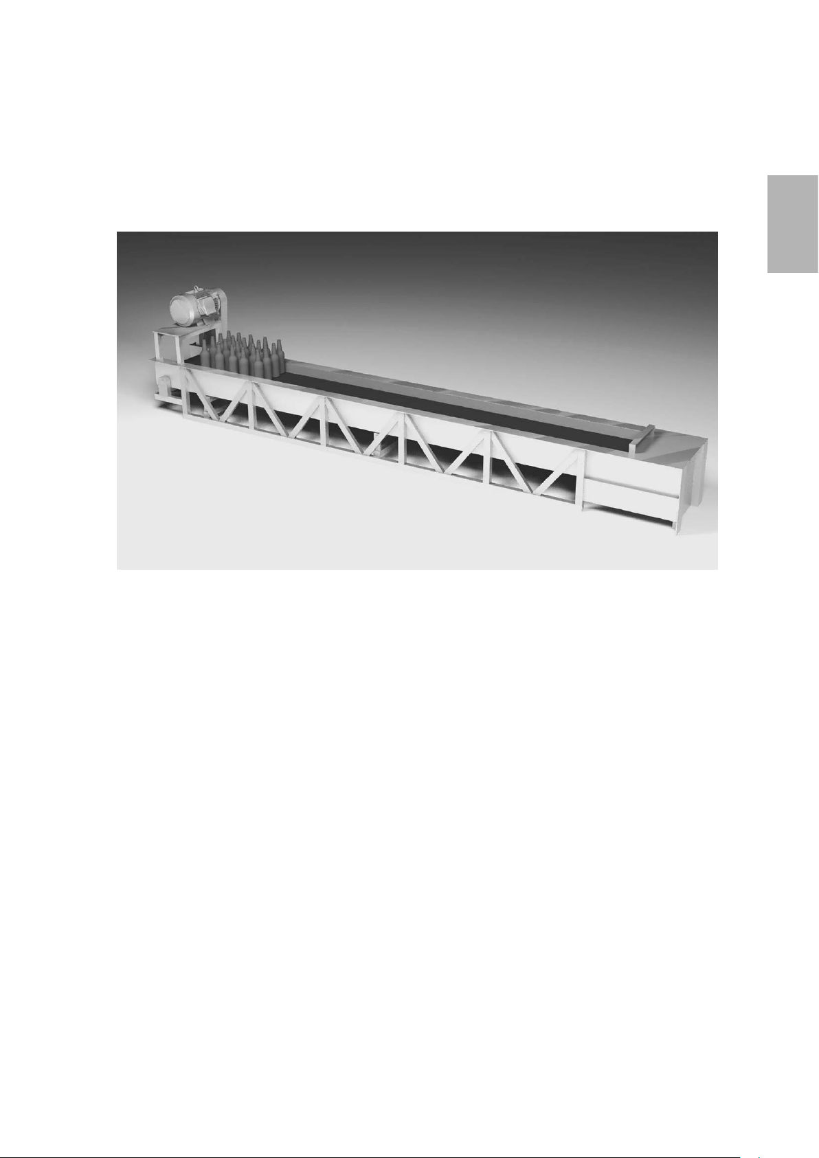
Belt conveyors used in factories
1
☆Improve efciency of work, braking at specic positions, automatic operation
● The inverter improves efciency of work and enable conveyors to be stopped at specic
positions.
● Conveyor speeds can be optimally adjusted depending on the work conditions.
● Soft starts and stops prevent products from moving around and falling off the conveyor.
● Conveyor acceleration and deceleration can be controlled such that shock to machines is
reduced or removed completely.
1-3
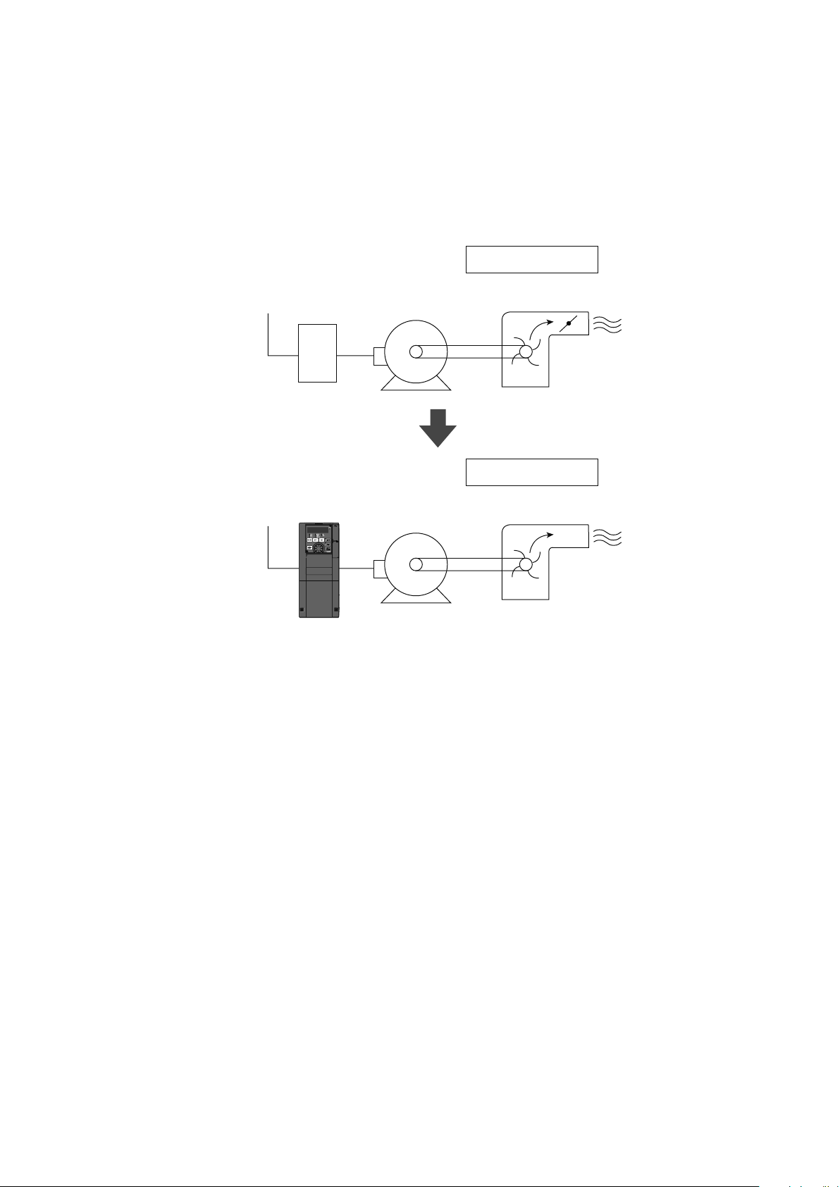
Fan, blower
Ventilation fans used in buildings
● Pump
● Fan, blower
● Ventilation fan
● Cooling tower
● Drying machine
(Furnace fan)
Switch
Inverter
Standard motor
Standard motor
Damper control
Damper
Fan, blower
Inverter control
☆The inverter achieves energy efciency and automation.
● Useful for air ow control (ow amount control)
● Automatic control over air ow (pressure or ow amount)
● Necessary amount can be changed according to seasons and day/night.
1-4
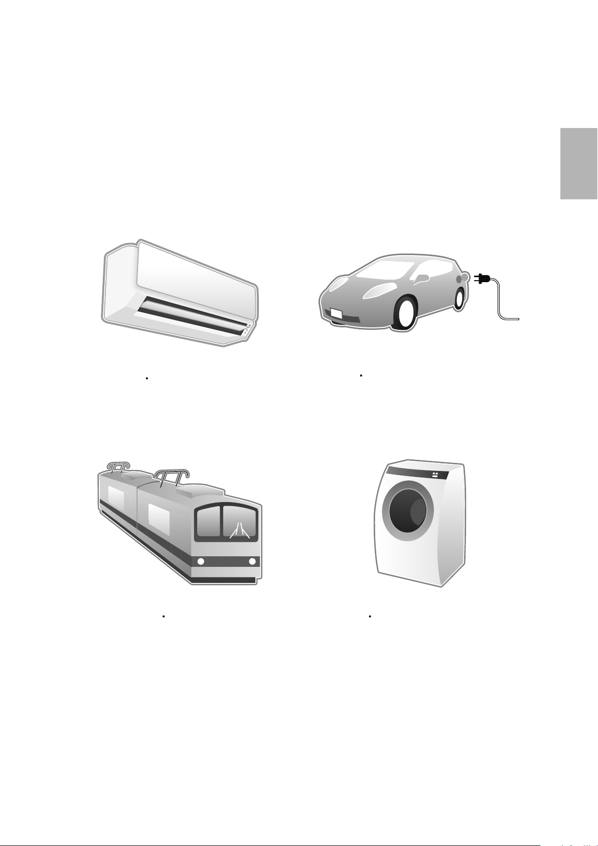
Inverters are used in these and many
devices we use every day.
other applications.
1
Air conditioner
Train
Electric vehicle
Washing machine
As you can see, inverters are used in the products and
1-5
1.2 Motor drive force
1.2.1 Motor and frequency
Motor speed is changed by varying the frequency of current owing through motors.
Frequency is discussed in more detail in this section.
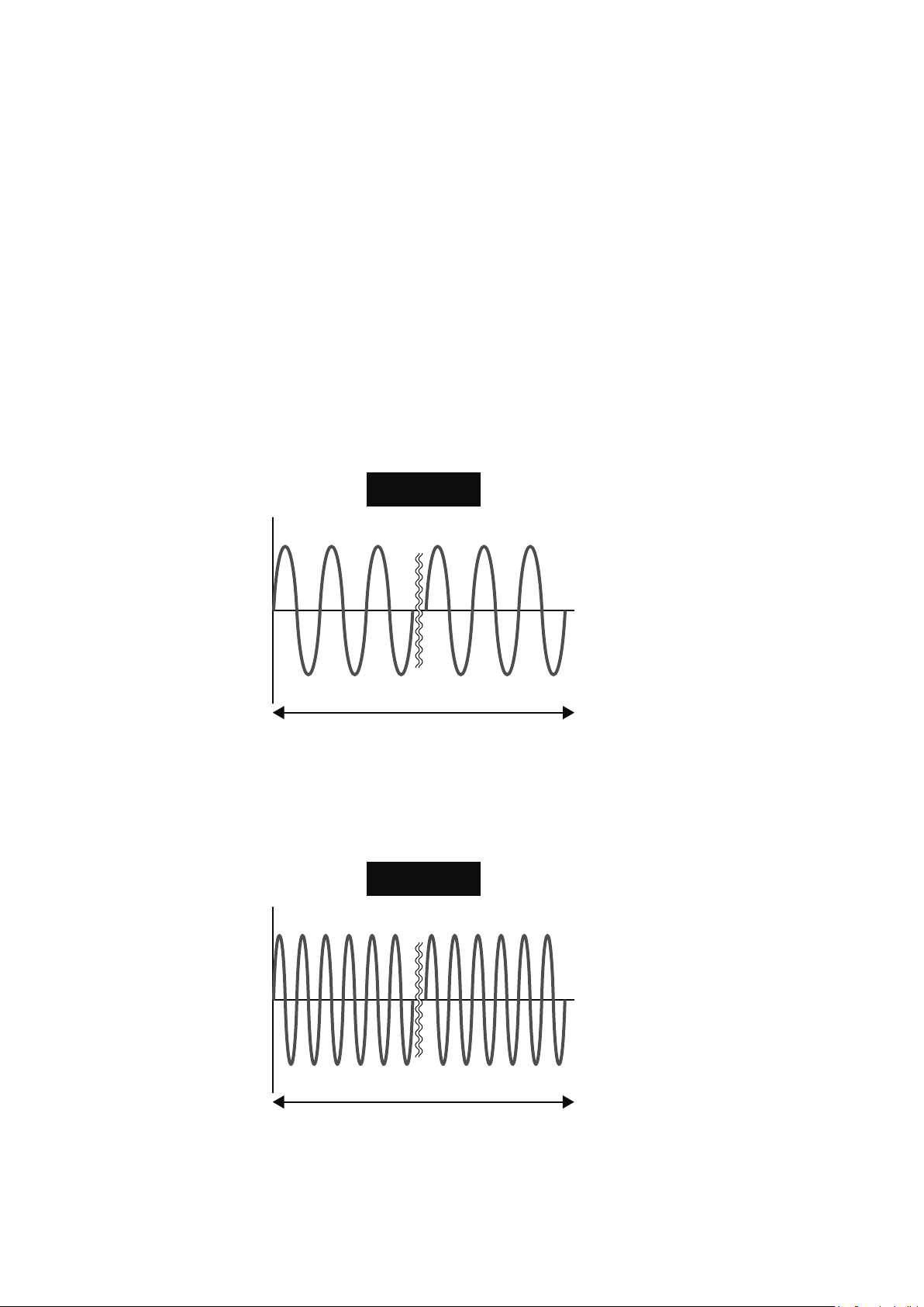
◎Frequency
Outlets in homes, for example, supply power at 100V/50Hz and 200V/60Hz specications.
"V" represents voltage and "Hz" represents the frequency.
Frequency values are usually shown in a graph like this. For example, frequency 60Hz means that there are 60
waves between positive and negative per second.
V
V
60Hz
t
60 cycles
1 sec
120Hz
1 sec
t
120 cycles
1-6

1
1.2.2 Principles of the motor
When a motor is connected to a source of power, current ows through the stator winding, or stator coil, within
the motor, which creates a rotating magnetic eld. This rotating magnetic eld causes the stator (rotor) to rotate.
Motor speed is proportional to the frequency of the power source.
Basically, the motor rotates by electromagnetic force.
Fan
Core
Rotor
Frame
Coil
Structure of the motor
1-7
1.3 Changing frequency
1.3.1 Structure of the inverter
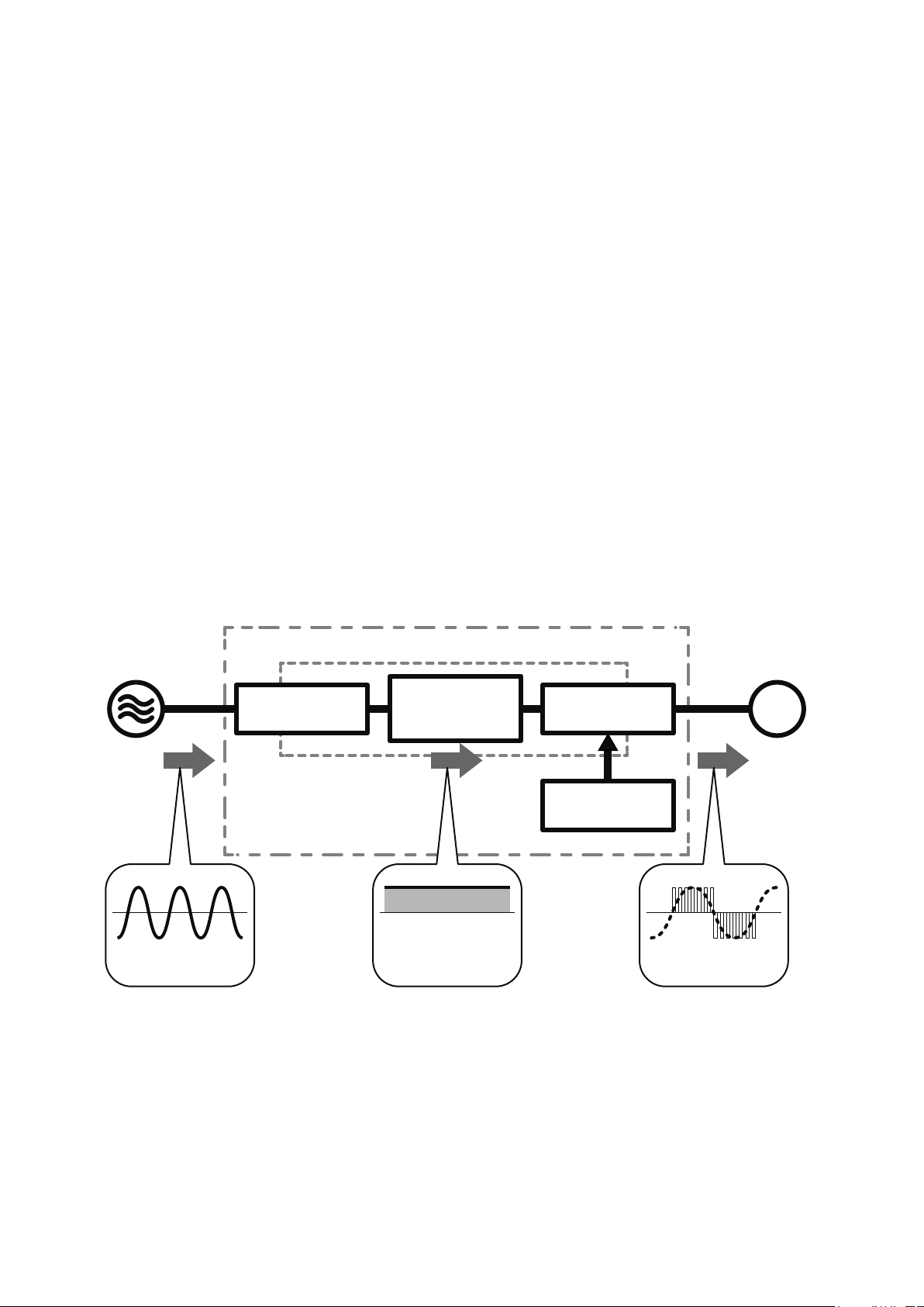
The inverter is generally comprised of 3 sections: converter section, inverter section, and control circuit.
◎Converter section
The converter section converts an AC of an AC power supply into a DC, and then smooths out the pulses of
current by the smoothing capacitor.
◎Inverter section
The inverter section converts the DC converted by the converter section into a pulsed current of
alternating current having variable frequency.
* Pulsed current refers to current that ows intermittently for short periods of time.
◎Control circuit
The control circuit controls the converter and inverter sections.
AC power supply
AC DC
Converter
section
Inverter
Main circuit
Smoothing
capacitor
Inverter
section
Control circuit
Standard
motor
IM
Variable voltage
Variable frequency
1-8

2
Inverter basics
Chapter 2
Specic models of the inverter
Mitsubishi general-purpose inverters
This chapter introduces several types of actual "inverters".
Mitsubishi offers many types of inverters to suit different purposes.
This chapter will cover the compact and high functionality FR-E700 model in detail.
Make sure the power is not turned on before connecting the power cable.
2-1
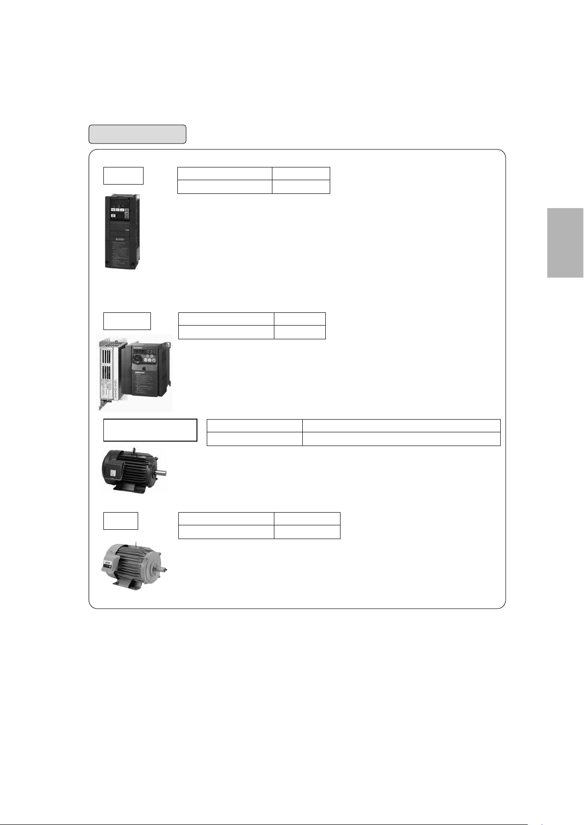
2.1 Mitsubishi general-purpose inverters
Three-phase 400V class
Three-phase 200V class
0.75kW to 55kW
0.75kW to 55kW
Three-phase 400V class
Three-phase 200V class
0.4K to 15K
0.4K to 15K
FR-F700PJ
Three-phase 400V class
Three-phase 200V class
0.75K to 110K
0.75K to 560K
FR-F800
●Service life of parts is extended. It comes with the service life diagnose function as standard.
●Compatible with various plug-in options.
Compatible with networks, such as LONWORKS and CC-Link, via plug-in options.
For fans and pumps
●Spring clamp terminals provide high reliability and easy wiring.
●Drives both the general-purpose motors and IPM motors. When it drives an IPM motor
(MM-EFS), which has permanent magnets embedded in its rotor, the energy saving and
high efficiency can be further achieved.
●Drives both the general-purpose motors and IPM motors. When it drives an IPM motor
(MM-EFS), which has permanent magnets embedded in its rotor, energy savings and high
efficiency can be further achieved.
SF-PR
●This model achieves the IE3 efficiency class with the same dimensions as those of
conventional models using our unique steel plate frame technology and new core materials.
●It maintains interchangeability with our standard-efficiency motor SF-JR for easy
replacement.
Three-phase 400V class
Three-phase 200V class
0.75kW to 55kW (75kW is to be released soon.)
0.75kW to 55kW (75kW to 160kW are to be released soon.)
MM-EFS (75kW or less)
MM-THE4 (75kW or more)
●This is an IPM motor, which has permanent magnets embedded in its rotor. It is more
efficient than an induction motor.
●Compared with the "MM-EF series", the motor loss (iron loss and primary copper loss) is
further reduced, and thus achieving higher efficiency. This motor satisfies the highest
efficiency standard IE4 (super premium efficiency).
●This inverter is suitable for fans and pumps, and has the various functions: optimum
excitation control, variable torque acceleration/deceleration patterns, PID control,
commercial power supply switching, adjustable 5 points V/F, continuous operation at an
instantaneous power failure, regeneration avoidance function, etc.
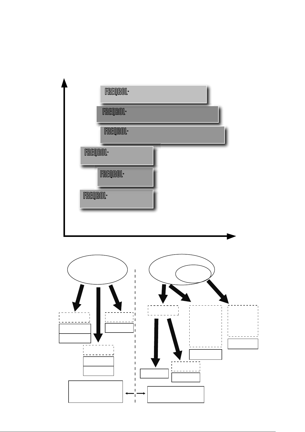
2.1.1 Lineup
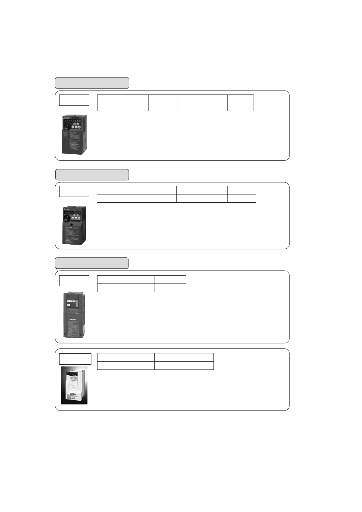
Inverter line-up
Functions and performance
Simple and compact inverter
Vector inverter
V500 (L)
Advanced functionality and high-performance inverter
A800
Energy-saving premium inverter
F800
Compact and powerful inverter
E700
F700PJ
Air conditioning inverter
D700
Applicable series for each industry
Fans and pumps
General industrial machine
Compact
FR-D700
Overcurrent shutdown level
is approx. 200% of the rated
current.
Compact
FR-D700
FR-F700PJ
More energy
saving
FR-F800
FR-F700PJ
Overcurrent shutdown
level is approx. 170%
(approx. 200% for FR-D700)
of the rated current.
High-
functionality
FR-F800
Web handling,
machine tool,
etc.
Highfunctionality
Highperformance
Closed-loop
(built-in option)
Torque control
Powerful
FR-E700
Capacity
Highperformance
Closed-loop
Torque control
FR-V500(L)
FR-A800
2-2
For fans and pumps
FR-F800
Three-phase 200V class
Three-phase 400V class
●Drives both the general-purpose motors and IPM motors. When it drives an IPM motor
(MM-EFS), which has permanent magnets embedded in its rotor, energy savings and high
efficiency can be further achieved.
●This inverter is suitable for fans and pumps, and has the various functions: optimum
excitation control, variable torque acceleration/deceleration patterns, PID control,
commercial power supply switching, adjustable 5 points V/F, continuous operation at an
instantaneous power failure, regeneration avoidance function, etc.
●Service life of parts is extended. It comes with the service life diagnose function as standard.
●Compatible with various plug-in options.
Compatible with networks, such as LONWORKS and CC-Link, via plug-in options.
FR-F700PJ
Three-phase 200V class
Three-phase 400V class
●Drives both the general-purpose motors and IPM motors. When it drives an IPM motor
(MM-EFS), which has permanent magnets embedded in its rotor, the energy saving and
high efficiency can be further achieved.
●Spring clamp terminals provide high reliability and easy wiring.
MM-EFS (75kW or less)
MM-THE4 (75kW or more)
●This is an IPM motor, which has permanent magnets embedded in its rotor. It is more
efficient than an induction motor.
●Compared with the "MM-EF series", the motor loss (iron loss and primary copper loss) is
further reduced, and thus achieving higher efficiency. This motor satisfies the highest
efficiency standard IE4 (super premium efficiency).
0.75K to 110K
0.75K to 560K
0.4K to 15K
0.4K to 15K
Three-phase 200V class
Three-phase 400V class
2
0.75kW to 55kW (75kW is to be released soon.)
0.75kW to 55kW (75kW to 160kW are to be released soon.)
SF-PR
Three-phase 200V class
Three-phase 400V class
0.75kW to 55kW
0.75kW to 55kW
●This model achieves the IE3 efficiency class with the same dimensions as those of
conventional models using our unique steel plate frame technology and new core materials.
●It maintains interchangeability with our standard-efficiency motor SF-JR for easy
replacement.
2-3
General industrial applications
(Suitable for transfer, conveyor, food packaging,
and standard machine tools, etc.)
FR-E700
General industrial applications
FR-D700
General industrial applications
Single-phase 100V class
Single-phase 200V class
● 0.5Hz 200% torque (0.1K to 3.7K) can be generated under Advanced magnetic flux
vector control.
● The non-slip M Dial with adaptive stroke speed allows for quick jumps or precise
increments based on turning speed.
● Compatible with various plug-in options.
The inverter is compatible with networks, such as CC-Link, PROFIBUS-DP, DeviceNet,
via plug-in options.
Single-phase 100V class
Single-phase 200V class
● Spring clamp terminals provide high reliability and easy wiring.
● It features the safety stop function and can comply with safety standards at a low cost.
● 1Hz 150% torque can be generated under General-purpose magnetic flux and with the
auto tuning function.
● The non-slip M Dial with adaptive scroll speed allows for quick jumps or precise
increments based on turning speed.
0.1K to 0.75K
0.1K to 2.2K Three-phase 400V class
(Suitable for transfer, conveyor, food packaging,
fans and pumps, etc.)
0.1K to 0.75K
0.1K to 2.2K Three-phase 400V class
(Suitable for lift, web line control, machine tools, etc.)
Three-phase 200V class
Three-phase 200V class
0.1K to 15K
0.4K to 15K
0.1K to 15K
0.4K to 15K
FR-A800
FR-V500 (L)
Three-phase 200V class
Three-phase 400V class
● PM sensorless vector control enables combinations with PM (magnetic) motor.
The auto-tuning function enables operation of other manufacturers' PM motors.
● Many useful features such as USB memory connectivity and PLC function
● True vector control possible through combinations with PLG motors
(requires the FR-A8AP internal option)
● Compatible with various plug-in options.
Also compatible with networks, such as CC-Link and SSCNETⅢ/H, via plug-in options.
Three-phase 200V class
Three-phase 400V class
● High-performance and quick-response operation via vector control of specialized motors
● Improved torque precision through high-precision calculations of internal
motor magnetic flux
● Adjustment-free speed control gain and position loop gain
● Compatible with operation over SSCNET communication via internal options
0.4K to 90K
0.4K to 500K
1.5 to 55K, 75K
1.5 to 55K and 75 to 250K
2-4
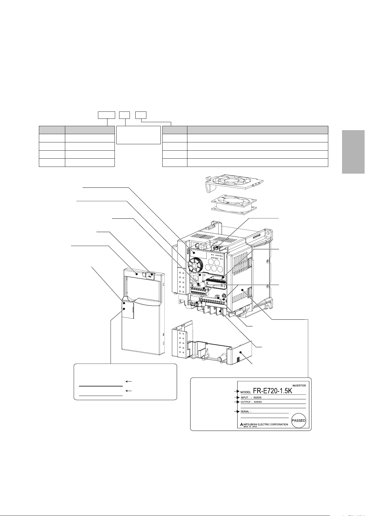
2.2 Detailed description of the inverter
2.2.1 Parts identication for the Mitsubishi
general-purpose inverter FR-E700 series
● Inverter model
FR - E720 - 1.5 K
No.
E720
E740
E720S
E710W
Operation panel
PU connector
Voltage/current input switch
USB connector cover
Front cover
PU connector cover
Voltage class
Three-phase 200V class
Three-phase 400V class
Single-phase 200V class
Single-phase 100V class
Represents the
inverter capacity [kW]
Symbol
None
SC
NF
NC
Control circuit terminal specification
Standard control circuit terminal (screw plug)
Models equipped with Safety Stop functionality
Models equipped with FL remote communication functionality
Models equipped with CC-Link communication functionality
Cooling fan
USB connector
(mini-B connector)
Connector for plug-in
option connection
Control circuit
terminal block
2
Capacity plate *
FR-E720-1.5K
SERIAL:
* Location of the capacity plate and the rating plate
differs according to the inverter capacity.
Refer to the outline dimension drawing.
● Accessory
Fan cover fixing screws (M3 × 35mm)
XXXXXX
Inverter model
Serial number
Changing the control
logic jumper connector
Main circuit
terminal block
Combed shaped
wiring cover
Rating plate *
Inverter model
Input rating
Output rating
Serial number
2-5
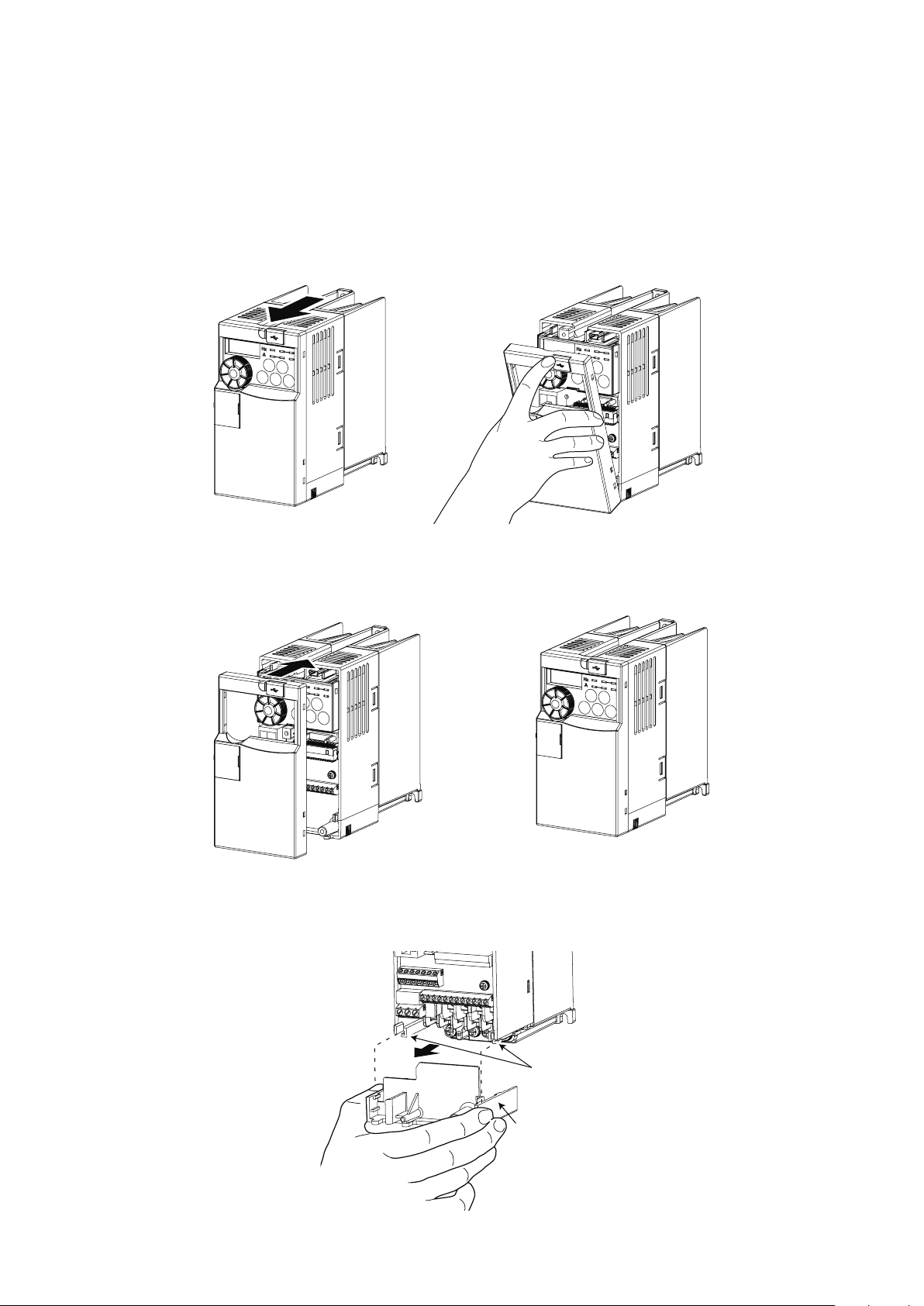
2.3 Connecting the inverter
2.3.1 Removing and installing the cover
Removal
Remove the front cover by pulling it toward you in the direction of arrow.
Reinstallation
To reinstall, match the cover to the inverter front and install it straight.
Wiring cover
Removes easily when pulled toward the front. Install the cover to the unit in alignment with the guide.
2-6
Guide
Wiring
cover
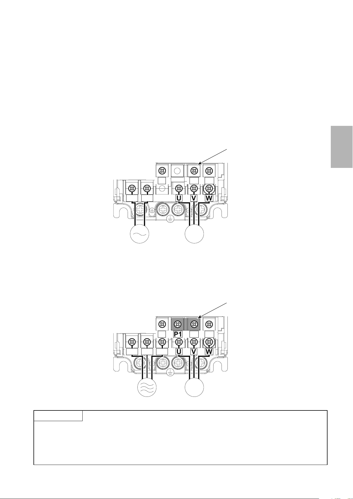
2.3.2 Connecting the power cable
Motor
Power supply
MotorPower supply
There are two types of power cables that can be used to connect to the inverter.
*Either the single-phase input type or three-phase input type cable is used depending on your power supply.
The single-phase input type is also further separated in 200V and 100V inputs. The output in either case is three-phase at 200V.
Single-phase two-wire power supply
This power supply is used for home electric appliances and small electric equipment.
The power supply is connected to the main circuit terminals R and S, and the motor is connected to terminals U, V,
and W.
Jumper
Screw size (M3.5)
2
N/-
P/+ PR
R/L1 S/L2
Screw size
(M3.5)
IM
Three-phase three-wire power supply
This power supply is for large electric equipment in factories.
The power supply is connected to the main circuit terminals R, S, and T, and the motor is connected to terminals U, V,
and W.
Jumper
Screw size (M3.5)
N/-
R/L1 S/L2 T/L3
P/+ PR
CAUTION
Screw size
(M3.5)
● Make sure the power cables are connected to the R/L1, S/L2, and T/L3 terminals. (Phase need not be matched.)
Never connect the power cable to the U, V, and W terminals on the inverter. Doing so will damage the inverter.
● Do not touch the main circuit terminals directly as this could cause electric shock.
IM
2-7
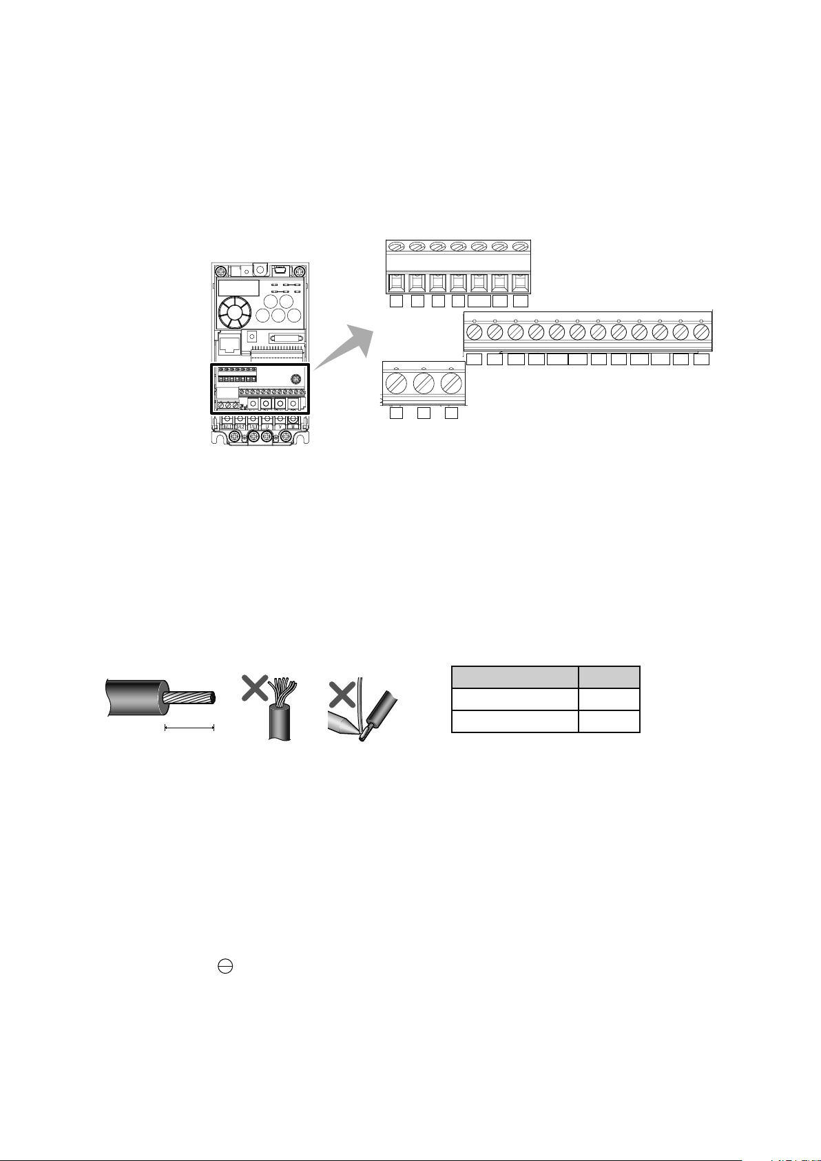
2.3.3 Control terminals
Cable sheath stripping length
Terminal screw size
M3: (Terminals A, B, and C)
M2: (All others)
Terminal layout
10 2 5 4 RUN FU SE
STF STR
RESMRS
FM
CBA
RHRMRL
PCSD
Wiring method
For the control circuit wiring, strip off the sheath of a cable and use as it is.
1.
Strip off the sheath about the size below. If the length of the sheath peeled is too long, a short circuit may
occur among neighboring wires. If the length is too short, wires might come off.
Wire the stripped wire after twisting it to prevent it from becoming loose. In addition, do not solder it.
L (mm)
Terminals A, B, and C 6
All others 5
L
SDSD
Loosen the terminal screw and insert the cable into the terminal.
2.
Tighten the screw according to the specied tightening torque.
3.
Under tightening may cause cable disconnection or malfunction. Over tightening may cause a short circuit
or malfunction due to damage to the screw or unit.
Tightening torque: 0.5N m to 0.6N m (terminals A, B, and C),
0.22N m to 0.25N m (terminals other than described above)
Screwdriver: small, at-blade screwdriver (tip thickness: 0.4mm/tip width: 2.5mm)
2-8
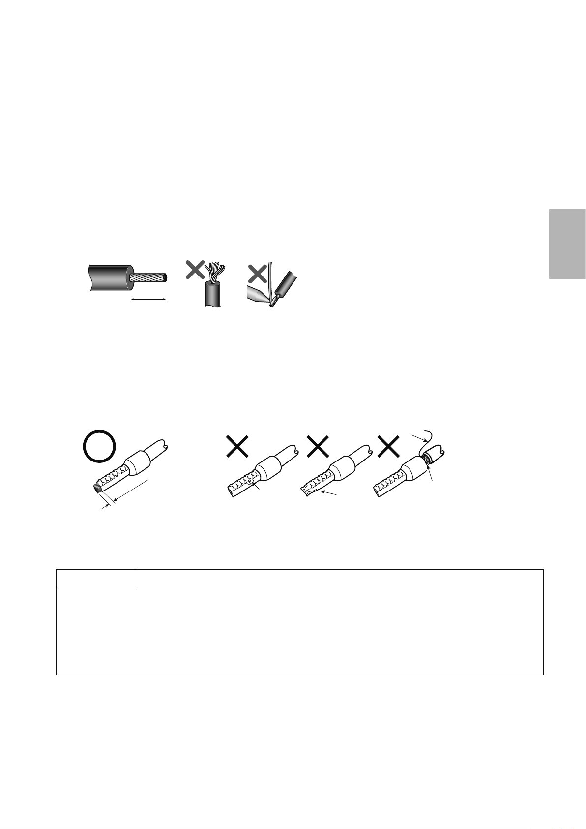
● Blade terminals
0 to 0.5m
Unstranded wires
Wires are not inserted
10mm
Cable sheath stripping length
Strip the sheath off of wires, and connect them to a blade terminal.
Strip off the sheath about the size below. If the length of the sheath peeled is too long, a short circuit may
1.
occur among neighboring wires. If the length is too short, wires might come off.
Wire the stripped wire after twisting it to prevent it from becoming loose. In addition, do not solder it.
Crimp the blade terminal.
2.
Insert wires to a blade terminal, and check that the wires come out for about 0 to 0.5mm from a sleeve.
Check the condition of the blade terminal after crimping. Do not use a blade terminal of which the crimp-
ing is inappropriate, or the face is damaged.
2
Wire
Shell
Sleeve
m
Damaged
Crumpled tip
into the shell
CAUTION
● When using stranded wires without a blade terminal, twist enough to avoid short circuit with a nearby
terminals or wires.
● Place the athead screwdriver vertical to the open/close button. In case the blade tip slips, it may cause an
inverter damage or injury.
2-9
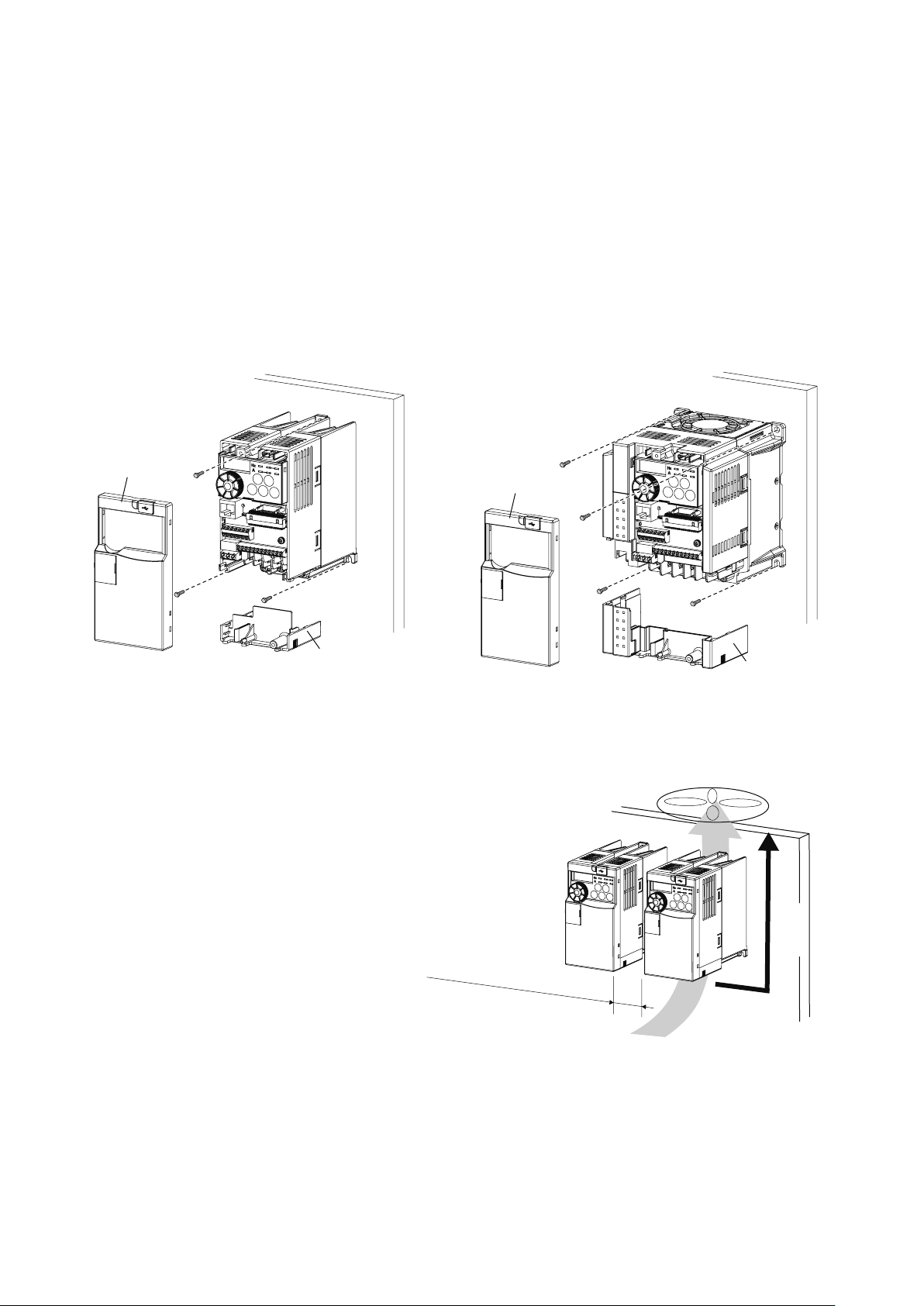
2.4 Inverter usage precautions
Front cover
Wiring cover
ەFR-E720-0.1K (SC) - 0.75K (SC)
ە
ە
ەFR-E720-1.5K (SC) or later
2.4.1 Installation of the inverter
Enclosure surface mounting
Remove the front cover and wiring cover to x the inverter to the surface.
FR-E720S-0.1K (SC) - 0.4K (SC)
FR-E710W-0.1K - 0.4K
ەFR-E740-0.4K (SC) or later
ەFR-E720S-0.75K (SC) or later
ەFR-E710W-0.75K
Front cover
Wiring cover
Install the inverter vertically.
Re
f
er t
o
the clearances be
low.
Vertical
2-10
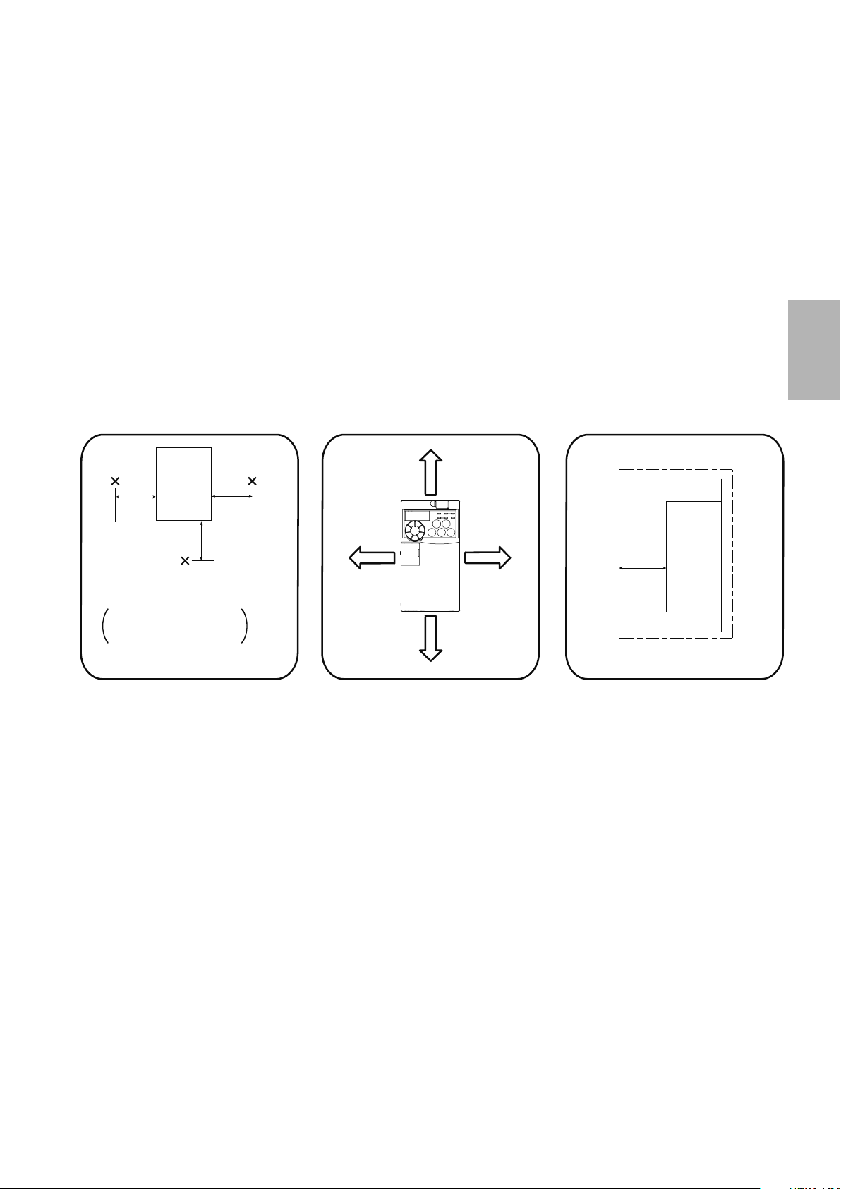
Surrounding air temperature
Installation orientation of the inverter
Install the inverter on a wall as specied. Do not mount it horizontally or in any other way.
Clearance around the inverter
To ensure ease of heat dissipation and maintenance, leave at least the shown clearances around the inverter.
At least the following clearances are required under the inverter as a wiring space, and above the inverter as a
heat dissipation space.
2
and humidity
Inverter
5cm 5cm
Measurement
position
Temperature: -10°C to +50°C
-10°C to +40°C for
totally enclosed
structure feature
Humidity: 90% RH or less
Leave enough clearances and take
cooling measures.
Measurement
position
5cm
Clearances (front)
10cm or
more
1cm or
more*
1cm or
more*
10cm or
more
* When using the inverters at the
surrounding air temperature of 40°C
or less, the inverters can be installed
without any clearance between them
(0cm clearance).
When surrounding air temperature
exceeds 40°C, clearances between
the inverters should be 1cm or more
(5cm or more for the 5.5K or more).
Clearances (side)
1cm
Inverter
or
more *
* 5cm or more for the 5.5K (SC) or
more
2-11
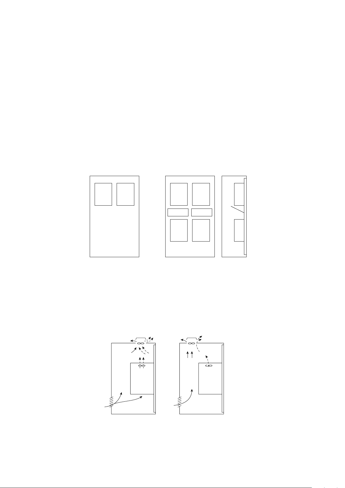
Above inverter
Arrangement of multiple inverters
Arrangement of the ventilation fan and inverter
Heat is blown up from inside the inverter by the small fan built in the unit.
Any equipment placed above the inverter should be heat resistant.
Arrangement of multiple inverters
When multiple inverters are placed in the same enclosure, generally arrange them horizontally as shown below in the
gure (a). When it is inevitable to arrange them vertically to minimize space, take such measures as to provide guides
since heat from the bottom inverters can increase the temperatures in the top inverters, causing inverter failures.
When mounting multiple inverters, fully take caution not to make the surrounding air temperature of the inverter
higher than the permissible value by providing ventilation and increasing the panel size.
InverterInverterInverter Inverter
Guide Guide
Inverter
Inverter
Guide
Enclosure Enclosure
(a) Arranged horizontally
(b) Arranged vertically
Arrangement of ventilation fan and inverter
Heat generated in the inverter is blown up from the bottom of the unit as warm air by the cooling fan. When installing a ventilation fan for that heat, determine the place of ventilation fan installation after fully considering an air ow.
(Air passes through areas of low resistance. Make an airway and airow plates to expose the inverter to cool air.)
Inverter Inverter
<Good example>
<Bad example>
2-12

2
2.4.2 Troubleshooting
When a fault occurs in the inverter, the inverter trips and the PU display automatically changes to one of the following fault or alarm indications.
◎Retention of fault output signal
When the magnetic contactor (MC) provided on the input side of the inverter is opened when a fault occurs,
the inverter's control power will be lost and the fault output will not be held.
◎Fault or alarm indication
When a fault or alarm occurs, the operation panel display automatically switches to the fault or alarm indication.
◎Resetting method
When a fault occurs, the inverter output is kept stopped. Unless reset, therefore, the inverter cannot restart.
When any fault occurs, take the appropriate corrective action, then reset the inverter, and resume operation.
Not doing so may lead to the inverter fault and damage.
Inverter fault or alarm indications are roughly categorized as below.
Error message
1
A message regarding operational fault and setting fault by the operation panel and parameter unit
(FR-PU04 /FR-PU07) is displayed. The inverter does not trip.
Warning
2
The inverter does not trip even when a warning is displayed. However, failure to take appropriate
measures will lead to a major fault.
Minor failure
3
The inverter does not trip. You can also output a minor failure signal by making parameter setting.
Major fault
4
<Reference>
Refer to Appendix 2 as it contains a list of fault displays and the appropriate troubleshooting steps to resolve the issue.
When a fault occurs, the inverter trips and a fault signal is output.
2-13

MEMO
2-14

3
Inverter basics
Chapter 3
Parameters
Inverter basics
You must have an understanding of parameters in order to congure "inverters".
We will use the belt conveyor example described in Chapter 1 again here. If the motor
moving the belt conveyor is not rotated smoothly, items on the belt conveyor could
fall off and break. The motor must be started slowly to ensure that the conveyor
moves smoothly.
The motor can be rotated smoothly in such a manner by conguring inverter parameters.
This chapter will introduce typically used parameters.
3-1

3.1 Setting basic parameters
3.1.1 Brief description of parameters
Parameters are the values used to congure inverter operation. These are notated as "Pr.". The type and number of parameters available differ depending on inverter model.
For simple variable-speed operation of the inverter, the initial values of the parameters may be used as they are.
Congure the necessary parameters in accordance with loads and operational specications. Parameters can
be congured, changed, and conrmed from the operation panel.
3.1.2 Typical parameters
The following table lists the most commonly used parameters.
Pr. Name Unit Initial value Range Application
Set when you want to increase a starting torque
0 Torque boost 0.1%
1 Upper-limit frequency 0.01Hz 120Hz 0 to 120Hz
2 Lower-limit frequency 0.01Hz 0Hz 0 to 120Hz
3 Base frequency 0.01Hz 60Hz 0 to 400Hz
Multi-speed setting
4
(high speed)
Multi-speed setting
5
(middle speed)
Multi-speed setting
6
(low speed)
7 Acceleration time 0.1 s 5s/10s/15s* 0 to 3600 s
8 Deceleration time 0.1 s 5s/10s/15s* 0 to 3600 s
Electronic thermal O/L
9
relay
79
Pr.CL Parameter clear 1 0 0, 1
ALLC All parameter clear 1 0 0, 1
Operation mode
selection
0.01Hz 60Hz 0 to 400Hz
0.01Hz 30Hz 0 to 400Hz
0.01Hz 10Hz 0 to 400Hz
0.01A
1 0
6%/4%/
3%/2%*
Inverter rated
current
0 to 30%
0 to 500A
0 External/PU switchover mode
1 Fixed to PU operation mode
2 Fixed to External operation mode
3
4
6 Switchover mode
7 External operation mode (PU operation interlock)
or when the motor with a load will not rotate,
resulting in an alarm [OL] and a trip [OC1].
* Initial values differ according to the inverter
capacity. (0.75K or lower/1.5K to 3.7K/5.5K,
7.5K/11K, 15K)
Congure this to set a limit on the maximum
output frequency.
Congure this to set a limit on the minimum out-
put frequency.
Congure this when the rate frequency of the
motor is not 60Hz.
Check the motor rating plate.
Congure this to change the preset speed
parameter with a terminal.
Acceleration/deceleration time can be set.
* Initial values differ according to the inverter
capacity.
(3.7K or lower/5.5K, 7.5K/11K, 15K)
External/PU operation mode 1
(Start command from External, frequency com-
mand from PU)
External/PU operation mode 2
(Frequency command from External, start com-
mand from PU)
Setting "1" returns all parameters except calibra-
tion parameters to the initial values.
Setting "1" returns all parameters to the initial
values.
POINT
● Parameters are congured with initial values so that inverters can operate without specic conguration.
Parameters can be congured in accordance with the motors and devices used in your environment.
3-2

3.2 Operation panel
3.2.1 Names and functions of the operation panel
The operation panel cannot be removed from the inverter.
Operation mode indication
PU: Lit to indicate PU operation mode.
EXT: Lit to indicate External operation
mode.
(Lit at power-ON at initial setting.)
NET: Lit to indicate Network operation
mode.
PU, EXT: Lit to indicate External/PU
These turn OFF when command
source is not on operation panel.
Unit indication
・Hz: Lit to indicate frequency.
・A: Lit to indicate current.
Monitor (4-digit LED)
Shows the frequency, parameter
number, etc.
M Dial
(M Dial: Mitsubishi inverter dial)
Used to change the frequency setting
and parameter values.
Press to display the following.
・Displays the set frequency in the
・Present set value is displayed during
・Displays the order in the faults history
Mode switchover
Used to change each setting mode.
Pressing simultaneously
changes the operation mode.
Pressing for a while (2s) can lock
operation.
Determination of each setting
If pressed during operation,
monitor changes as below;
operation mode 1, 2.
(Flickers when the set frequency
monitor is displayed.)
(Both "Hz" and "A" turn OFF when
other than the above is displayed.)
monitor mode
calibration
mode
Running frequency
Operating status indication
Lit or flicker during inverter operation.
* ON: Indicates that forward rotation
operation is being performed.
Slow flickering (1.4s cycle):
Reverse rotation operation
Fast flickering (0.2s cycle):
When was pressed or the
start command was given, but the
operation can not be made.
・When the frequency command is
less than the starting frequency.
・When the MRS signal is input.
Parameter setting mode
Lit to indicate parameter setting mode.
3
Monitor indication
Lit to indicate monitoring mode.
Stop operation
Used to stop Run command.
Fault can be reset when protective
function is activated (major fault).
Operation mode switchover
Used to switch between the PU and
External operation mode.
When using the External operation
mode (operation using a separately
connected frequency setting
potentiometer and start signal), press
this key to light up the EXT indication.
(Press simultaneously (0.5s),
or change Pr. 79 setting.)
PU: PU operation mode
EXT: External operation mode
Cancels PU stop also.
Start command
The rotation direction can be selected
by setting Pr. 40.
Output current
Output voltage
3-3

3.3
Potentiometer
Switch
)
Selecting the operation mode and command source
3.3.1 Various operation modes
One of the key features of the inverter is the capability to be controlled with various signals.
The operation mode species the source of start commands and frequency commands.
PU operation mode
PC
(FR Configurator
GOT
POINT
Parameter unit
FR-PU07
PC
Programmable controller
PU operation mode
Network
operation mode
Operation panel
PU connector
Communication
option card
Control terminal
Inverter
USB
connector
PU operation mode
External
operation mode
5
4
6
3
7
2
8
1
9
10
● Mitsubishi Electric factory automation devices such as programmable controllers and GOTs are equipped
with Mitsubishi general-purpose inverter protocols for easy integration by simply connecting cables and con-
guring communication settings.
3-4

3.3.2 Operation mode selection (Pr. 79)
Used to select the operation mode of the inverter. Mode can be changed as desired among operation using external command signals (External operation), operation from the operation panel and PU (FR-PU07/FR-PU04)
(PU operation), combined operation of PU operation and External operation (External/PU combined operation),
and Network operation (when RS-485 communication or a communication option is used).
Initial
Pr. Name
value
Setting
range
Description LED Indication
79
Operation
mode
selection
Use External/PU switchover mode (
between the PU and External operation mode.
0
At power on, the inverter is in the External operation
mode.
Fixed to PU operation mode
1
Fixed to External operation mode
Operation can be performed by switching between the
2
External and NET operation mode.
External/PU operation mode 1
Frequency command Start command
Operation panel and PU
(FRPU04/FR-PU07)
3
setting or external signal
input (multi-speed setting,
across terminals 4-5 (valid
when AU signal turns ON)).*
0
External/PU operation mode 2
Frequency command Start command
External signal input
(terminal STF, STR)
) to switch
External operation mode
PU operation mode
External operation mode
NET operation mode
3
External signal input
4
(terminal 2, 4, JOG,
multi-speed selection, etc.)
Switchover mode
Switchover between PU operation, External operation,
and NET operation is available while keeping the same
6
operation status.
External operation mode (PU operation interlock)
X12 signal ON
Operation mode can be switched to the PU operation
7
mode. (output stop during external operation)
X12 signal OFF
Operation mode can not be switched to the PU
operation mode.
Enter from
operation panel and
and
(FR-PU04/FR-PU07)
of the
of the PU
PU operation mode
External operation mode
NET operation mode
PU operation mode
External operation mode
* The priority of frequency commands when Pr. 79="3" is: Multi-speed operation (RL/RM/RH/REX) > PID control
(X14) > terminal 4 analog input (AU) > Digital input from the operation panel.
3-5

3.4 Basic operation modes
5
6
3.4.1 External operation mode
External operation mode is used to input start and frequency commands with external potentiometers and
switches connected to the control circuit terminal.
4
7
3
Forward
rotation start
Reverse
rotation start
8
9
10
Hz
Inverter
STF
STR
SD
Frequency setting
potentiometer
3.4.2 PU operation mode
PU operation mode is used to input start and frequency
commands with operation panels or parameter units
(FR-PU04/FR-PU07).
10
2
5
3-6
Operation panel

3.4.3 External/PU operation mode 1
Select the External/PU operation mode 1 when
applying frequency command from the operation panel
or parameter unit (FR-PU04/FRPU07) and inputting
the start command with the external start switch.
Inverter
Forward
rotation start
Reverse
STF
STR
rotation start
SD
3.4.4 External/PU operation mode 2
Select the External/PU operation mode 2 to input
frequency commands from an external potentiometer
or multi-speed and JOG signals,
or to input start commands via key operation of the
operation panel or parameter unit (FR-PU04/FR-PU07).
• Select "4" for Pr. 79. You cannot change to the other
operation mode.
5
6
4
7
3
8
9
10
Hz
Operation panel
3
Frequency setting
potentiometer
3-7
Inverter
Operation panel
10
2
5

3.5 How to congure parameters
3.5.1 Parameter clear/All parameter clear
Parameter settings may have been changed if the inverter is used.
Use this procedure to restore parameters to their initial values.
Operation Display
Screen at power-ON
1
2
The monitor display appears.
Changing the operation mode
Press to choose the PU operation mode.
PU indication is lit.
Parameter setting mode
3
Press to choose the parameter setting
mode.
Selecting the parameter number
4
Turn until ( ) appears
Reading settings
5
Press to read the present setting.
"
"(initial value) appears.
Changing the setting
6
Turn to change it to the set value " ".
Parameter settings
7
Press to nalize the setting.
"1" and "Pr.CL"/"ALLC" ashes.
PRM indication is lit.
(The parameter number read previously appears.)
Parameter clear
All parameter clear
Parameter clear
All parameter clear
Setting Description
0 Not executed.
Set parameters back to the initial values. (Parameter clear sets back all parameters except calibration
1
parameters, terminal function selection parameters to the initial values.) Refer to the parameter list for
information on the availability of clear parameter and clear all parameters functions for each parameter.
POINT
● Check the values of several parameter settings when the clear all parameters function cannot be performed.
Pr. 77 "0", Pr. 79 "0", Pr. 340 "10", and Pr. 551 "9999"
3-8

3.5.2 Pr. 9 Electronic thermal O/L relay
Congure the current value for the electronic thermal O/L relay to enable motor overheating protection. This can
help you achieve optimal protection capability for various operating conditions such as low-speed operation and
reduced motor cooling capacity.
Pr. Name Initial value Setting range Description
*1
9 Electronic thermal O/L relay Inverter rated current
*1 The inverter rated current is congured to 85% for values of 0.75K or less.
This function detects the motor overload (overheating) and trips the inverter by stopping the operation of the
transistor at the inverter output side.
● Set the rated current value (A) of the motor in Pr. 9.
(If the motor has both 50Hz and 60Hz rating and the Pr. 3 Base frequency is set to 60Hz, set the 1.1 times of
the 60Hz rated motor current.)
● Set "0" in Pr. 9 when you do not want to operate the electronic thermal O/L relay, e.g. when using an external
thermal relay with the motor. (Note that the output transistor protection of the inverter functions (E.THT).)
Operation example
0 to 500A Set the rated motor current.
3
Screen at power-ON
1
The monitor display appears.
Changing the operation mode
2
Press to choose the PU operation mode. The [PU] indicator turns on.
Parameter setting mode
3
Press to choose the parameter setting mode.
Selecting the parameter number
4
Turn until (Pr. 9) is selected.
Reading settings
5
Press to read the present setting. " " (0.68A (initial value)) appears.
Changing the setting
6
Turn to change the setting to " " (0.63A).
Parameter settings
7
Press to nalize the setting.
The parameter number and setting ashes.
* Congure parameter settings in accordance with your environment.
3-9

3.5.3 Pr. 3 Base frequency
Use this function to adjust the inverter output (voltage, frequency) to match the motor rating.
Pr. Name Initial value Setting range Description
3 Base frequency 60Hz 0 to 400Hz
● When operating a standard motor, generally set the rated frequency of the motor to Pr. 3 Base frequency.
When running the motor using commercial power supply-inverter switch-over operation, set Pr. 3 to the same
value as the power supply frequency.
● If the frequency given on the motor rating plate is "50Hz" only, always set to "50Hz". Leaving the base fre-
quency unchanged from "60Hz" may make the voltage too low and the torque insufcient. It may result in an
inverter trip due to overload.
Rated motor frequency.
(50Hz/60Hz)
Screen at power-ON
1
The monitor display appears.
Changing the operation mode
2
Press to choose the PU operation mode. The [PU] indicator turns on.
Parameter setting mode
3
Press to choose the parameter setting mode.
Selecting the parameter number
4
Turn until (Pr. 3) is selected.
Reading settings
5
Press to read the present setting. " " (60.00Hz (initial value)) appears.
Changing the setting
6
Turn to change the setting to " " (50.00Hz).
Parameter settings
7
Press to nalize the setting.
Operation example
The parameter number and setting ashes.
* Congure parameter settings in accordance with your environment.
3-10

3.5.4 Pr. 0 Torque boost
Pr
y
Output frequency (Hz)
This parameter is used to correct voltage drops in low-frequency ranges and improve decreases in motor torque
during low speeds.
•
Motor torque during low-frequency ranges can be adjusted in accordance with load and can be increased during startup.
Pr. Name Initial value Setting range Description
0.1K to 0.75K 6%
0 Torque boost
1. Starting torque adjustment
● On the assumption that Pr. 19 Base frequency
voltage is 100%, set the output voltage at 0Hz in %
to Pr. 0.
1.5K to 3.7K 4%
5.5K, 7.5K 3%
11K, 15K 2%
0 to 30% Set the output voltage at 0Hz as %.
100%
● Adjust the parameter little by little (about 0.5%),
and check the motor status each time. If the setting
is too large, the motor will overheat. The guideline
is about 10% at the greatest.
Operation example
Screen at power-ON
1
The monitor display appears.
Changing the operation mode
2
Press to choose the PU operation mode. The [PU] indicator turns on.
Parameter setting mode
3
Press to choose the parameter setting mode.
Selecting the parameter number
4
Turn until (Pr. 0) is selected.
Reading settings
5
Press to read the present setting. " " (6.0% (initial value)) appears.
Output voltage
.0 Setting range
3
0
Base
frequenc
Changing the setting
6
Turn to change the setting to " " (3.0%).
Parameter settings
7
Press to nalize the setting.
The parameter number and setting ashes.
* Congure parameter settings in accordance with your environment.
3-11

3.5.5 Pr. 1, 2 Upper-limit/lower-limit frequency
Output frequency
Frequency setting value
lower-limit frequency
These parameters can be used to restrict motor speed.
These parameters are used to set upper and lower limits on output frequency.
Pr. Name Initial value Setting range Description
1 Upper-limit frequency 120Hz 0 to 120Hz Upper limit of the output frequency
2 Lower-limit frequency 0Hz 0 to 120Hz Lower limit of the output frequency
(1) Set upper-limit frequency
● Use Pr. 1 Upper-limit frequency to set the maximum
frequency. If the frequency of the frequency
command
output frequency is clamped at the upper-limit
frequency.
(2) Set lower-limit frequency
● Use Pr. 2 Lower-limit frequency to set the minimum
frequency.
● If the set frequency is less than Pr. 2, the output
frequency is clamped at Pr. 2 (will not fall below Pr. 2 ).
entered is higher than the setting, the
Operation example
Screen at power-ON
1
The monitor display appears.
(Hz)
Pr.1
Pr.18
Pr.2
Clamped at the
0
(4mA)
Clamped at the
upper-limit frequency
5, 10V
(20mA)
2
3
4
5
6
7
* Congure parameter settings in accordance with your environment.
Changing the operation mode
Press to choose the PU operation mode. The [PU] indicator turns on.
Parameter setting mode
Press to choose the parameter setting mode.
Selecting the parameter number
Turn until (Pr. 1) is selected.
Reading settings
Press to read the present setting. " " (120.0Hz (initial value)) appears.
Changing the setting
Turn to change the setting to " " (60.00Hz).
Parameter settings
Press to nalize the setting.
The parameter number and setting ashes.
3-12

3
3.5.6 Pr. 7, 8 Acceleration/deceleration time
e
Pr.20
Pr.7 Pr.8
frequency
Pr.44 Pr.45
These parameters are used to congure the motor acceleration/deceleration time.
Set larger values for slower acceleration/deceleration and smaller values for faster acceleration/deceleration.
Pr. Name Initial value Setting range Description
3.7K or less 5s
7 Acceleration time
11K, 15K 15s
3.7K or less 5s
8 Deceleration time
11K, 15K 15s
Acceleration/
20
(1) Acceleration time setting (Pr. 7, Pr. 20)
● Pr. 7 acceleration time congures the acceleration
time required to reach the Pr. 20 acceleration/
deceleration reference frequency from a stopped state.
deceleration
reference
frequency
60Hz 1 to 400Hz
0 to 3600/360s Motor acceleration time5.5K, 7.5K 10s
0 to 3600/360s Motor deceleration time5.5K, 7.5K 10s
Frequency that will be the basis of
acceleration/deceleration time
As acceleration/deceleration time, set the
frequency change time from stop to Pr. 20.
Running
frequency
(Hz)
(2) Deceleration time setting (Pr. 8, Pr. 20)
● Pr. 8 acceleration time congures the deceleration
time required to stop from the Pr. 20 acceleration/
deceleration reference frequency.
Operation example
Screen at power-ON
1
The monitor display appears.
Changing the operation mode
2
Press to choose the PU operation mode. The [PU] indicator turns on.
Parameter setting mode
3
Press to choose the parameter setting mode.
Selecting the parameter number
4
Turn until (Pr. 7) is selected.
Reading settings
5
Press to read the present setting. " " (5.0 seconds (initial value)) appears.
Changing the setting
6
Turn to change the setting to " " (10.0 seconds).
Parameter settings
Output
Accelerationtime
Tim
Decelerationtime
7
Press to nalize the setting.
The parameter number and setting ashes.
* Congure parameter settings in accordance with your environment.
3-13

MEMO
3-14

4
Controlling inverters using a PC
Chapter 4
How to use FR Congurator
Using FR Congurator makes parameter
conguration even easier.
Many parameters can be congured in single batch operations with the software
"FR Congurator".
This chapter will cover how to connect the inverter to a PC, Easy Setup, and nally
basic operation of the software.
Using this software also enables you to save conguration data for devices.
You can easily take congurations created for testing and prototype environments
and copy them to mass-production equipment and devices.
4-1

4.1
Example of FR-E700
Pull the cover in the direction of arrow. Then turn it upward.
Inverter PC (FR Configurator) USB cable
Fundamental knowledge to operate FR Congurator
4.1.1 Items needed for connectivity
4.1.2 Connection method
All you need to connect a PC and inverter is a single USB cable. Only peer-to-peer connections can be
established. USB hubs cannot be used to make connections.
USB cable
USB connector
<How to open the USB connector cover>
4-2

4.1.3 Startup
The "Startup" window is displayed when FR Congurator is started. Each function can be directly selected from
the "Startup" window.
A
B
C
D
E
No. Name Function and description
Shows up to ve recent used les.
A Open
B Easy Setup
C Functions Shows a list of functions.
D Help Displays Help window.
E Cancel Click to close this window, and returns to Main frame.
Point a cursor on "Open", and ve recent used les are shown. Click the le name, then
"Startup" window is closed, and Main frame is displayed with the le contents reected.
Click to start Easy Setup.
From System Property setting to Model setting and parameter setting, the system setting
up is easily made with wizard style (interactive manner).
4
4-3

4.1.4 Screen conguration (Main frame)
The Main frame (main window) of FR Congurator consists of three areas.
• Navigation area
An area for showing information of the registered inverter, or for making settings. "Test Operation", "System
Settings", "Setting Wizard", and "Troubleshooting" are available in this area.
• Monitor area
An area for showing obtained monitor data of the inverter. "Graph", "I/O Terminal Monitor", "Machine Analyzer",
"Batch Monitor" are available in this area.
• System area
An area for showing and read/write parameters, or for converting from parameter setting of conventional model.
"Parameter List", "Diagnosis" and "Convert" are available in this area.
H
A
B
C
G
I
F
Navigation area
D
No. Name Function and description
A Title bar
B Menu bar Each function is available by selecting from the menu.
C Tool bar Each function is available by clicking icons of the tool bar.
D Status bar The model name, Operating status, etc. are shown.
"FR Congurator SW3" is displayed on the title bar. If a system le has been read, or has been
saved, the le name is displayed.
Monitor area
E
F
System area
E Split line Adjustment of System area size and Monitor area size is available.
F Conceal button Conceals the Monitor area and System area.
G Minimize button Minimizes the Main frame window size of FR Congurator.
H Maximize button Maximizes the Main frame window size of FR Congurator.
I Close button Closes FR Congurator.
4-4

4.1.5 Screen conguration (Navigation area)
The Navigation area is for showing registered inverter information, switching of operation mode and ONLINE/
OFFLINE, sending of start/stop command, changing of the set frequency, or starting Setting Wizard. "Test
Operation", "System Settings", "Troubleshooting" and "Setting Wizard" are available in this area.
The Upper part of the Navigation area displays "Test Operation", and the lower part displays "System View".
Select [System Setting], [Troubleshooting] or [Setting Wizard] under [View] menu to switch the function
displayed in "System View".
"Test Operation"
4
"System Settings" "Troubleshooting" "Setting Wizard"
4-5

4.1.6 Screen conguration (System area)
The System area is for showing and reading/writing parameters, or for diagnosis and converting from parameter
setting of conventional model. "Parameter List", "Diagnosis", and "Convert" are available in this area.
Select [Parameter List], [Diagnosis], or [Convert] under [View] menu, or click icons on the tool bar to switch the
function displayed in the System area.
"Parameter List"
"Diagnosis" "Convert"
4-6

4.1.7 Screen conguration (Monitor area)
Monitor area is for showing obtained monitor data of inverter. "Graph", "I/O Terminal Monitor", "Machine Analyzer",
and "Batch Monitor" are available in this area.
Select [Graph], [Machine Analyzer], [Batch Monitor], or [I/O Terminal Monitor] under [View] menu, or click an
icon on the tool bar to display the function in Monitor area.
"Graph" "Machine Analyzer" "I/O Terminal Monitor" "Batch Monitor"
4
4-7

4.2 Easy Setup
4.2.1 Conguration method
Setting from system setting to parameter setting is easily performed with Easy Setup. Even without FR Congurator
knowledge, without regard to the parameter number, system setting and basic parameter setting is easily performed.
Easy Setup
System Property
Communication Setting
Inverter Setting Method
Automatic?
Manual?
Manual
Model Setting
Inverter Selection
Finished?
Parameter setting?
Select a station number,
and click [Next]
Automatic
Automatic Detection
[Finish]
Set System Property.
Input system name and comment.
Make communication setting between the inverter
and a PC.
Select inverter setting method in Easy Setup.
Select between automatic detection or manual
model setting.
When "Perform Automatic Recognition of the
Connected Inverter" is selected in "Inverter Setting
Method" window, then connected inverter is
automatically detected.
If "Perform system setting manually" is selected,
then set station number, inverter model, capacity
and plugin option manually.
Fix the system setting configured so far.
After fixing the system setting, parameter setting is
available.
Choose an inverter (station number) for parameter
setting, and click [Next].
Click [Finish] to close Easy Setup, and proceeds to
the Main frame window.
Control Method
Motor Setting
Start Command and Frequency
(Speed) Setting Method
Parameter List
(Confirmation of parameter setting)
Main frame
Select the control method.
Input motor information.
Select the start command input method and
frequency (speed) setting input method.
The configured parameter setting based on the
setting input is displayed in a list.
4-8

4.2.2 System property
Input an information for creating a system le.
Type a system name (up to 32 one byte characters) for this system le. Click [Next] after inputting the system
name. When [Next] is clicked, the screen proceeds to "Communication Setting".
A
B
C
F
No. Name Function and description
A System Property Shows description of current setting and next/previous setting in Easy Setup.
System Name Type a system name up to 32 one byte characters.
B
Comment A eld for comments (up to 256 one byte characters) to describe the system.
C
Next> Proceeds to "Communication Setting".
D
E Cancel Disables the settings and closes Easy Setup.
F Help Displays Help window.
E D
4
4-9

4.2.3 Communication setting
Adjust the communication setting between a PC and the inverter.
When communicating with the inverter using an USB port of the PC, select "USB" in "PC side Port" eld,
Click [Next].
When communicating with the inverter using a serial port of the PC, select "RS-232C" in "PC side Port" eld.
POINT
● The communication setting is used for an initial value of inverter.
● Check the PC-side port (serial/USB) and PC port number (1 to 63).
A
D
E
F
No. Name Function and description
PC side Port RS-232C
A
Port Number 1 Select the PC communication port number.
B
Through None Select when connecting through GOT.
C
Communication Speed 19200 Set the communication speed.
D
Data Length 8 Set the data bit length.
E
Parity Even Specify the parity bit
F
Stop Bit 2 Set the stop bit length.
G
Delimiter CR Specify the delimiter of the data end.
H
Advanced
I
J Default Value Restores the initial communication setting of the inverter.
Next> Proceeds to "Inverter Setting Method".
K
<Back Returns to "System Setting".
L
M Cancel Disables the settings and closes Easy Setup.
N Help Displays Help window.
Initial value
Select the communication port from RS-232C or USB. (USB communication is
only available with FR-A700, A701, B, B3, E700EX and E700(SC)(NC) series.)
Displays "Advanced" window. Setting of timeout and number of retry is available.
B C
N
G
H
I
J
M
K
L
4-10

4.2.4 Inverter setting method
Select inverter setting method between automatic recognition of the connected inverter, or manually model
setting for this system.
A
B
D CEF
No. Name Function and description
Perform Automatic Recognition of
A
the Connected Inverter
Perform Model Setting Manually Make the model setting manually.
B
Next>
C
<Back Returns to "Communication Setting".
D
E Cancel Closes Easy Setup with the invalid setting.
F Help Displays Help window.
Choose "Perform Automatic Recognition of the Connected Inverter" and click to
[Next] automatically detect the connected inverter. After nishing the automatic
detection of the inverter, the window proceeds to "Inverter Selection".
When "Perform Automatic Recognition of the Connected Inverter" is selected,
the window proceeds to "Automatic Detection". If "Perform Model Setting
Manually" is selected, the window proceeds to "Model Setting".
4
4-11

4.2.5 Automatic detection
Click [Next] to detect inverter of which communication is available.
A
B
C
D
GH
No. Name Function and description
Shows a state of automatic detection. When an inverter is detected, the color turns blue, and
A Message area
B Detection Results
Start Starts automatic detection when clicked.
C
Abort Aborts automatic detection.
D
Next> Proceeds to "Inverter Selection".
E
<Back Returns to "Inverter Setting Method".
F
G Cancel Disables the settings and closes Easy Setup.
H Help Displays Help window.
shows a result of detection. (If an error occurred during automatic detection, the color turns
red, and shows error description.)
Shows a result of automatic detection. A station during detecting is displayed in blue. And
when an inverter is detected, inverter model name is displayed. (For a station failed for detec-
tion, the color turns red, and shows error code.)
F E
4-12

4.2.6 Inverter selection
Click [Register System Setting] to register the system setting, and then parameter setting becomes available.
Choose an inverter (station number) for parameter setting, and click [Next]. After parameter setting is nished,
the window returns to "Inverter Selection" again. To congure parameters on multiple devices, return to this
screen and select another inverter (station number) after you have nished conguring parameters on a
particular inverter.
Click [Finish] to close Easy Setup, and proceeds to the Main frame window.
A
B
E DFG C
No. Name Function and description
Register System Setting Register the system setting congured in Easy Setup.
A
Shows the inverter reected into the system setting. Choose a station number for
parameter setting, and click [Next].
B Inverter selecting eld
Finish Click to close Easy Setup, and proceeds to the Main frame window.
C
Next> Proceeds to "Control Method".
D
<Back Returns to "Model Setting", "Automatic Detection", or "Parameter List".
E
F Cancel Disables the settings and closes Easy Setup.
G Help Displays Help window.
A check mark is displayed on the station number if the parameter setting has been
already congured. (Click [Register System Setting] to register the system setting rst,
and the eld becomes available.)
4
4-13

4.2.7 Control method
From the "Control Method" screen, set a control method of the inverter selected in "Inverter Selection" window.
Select the control method, and click [Next].
A
B
D CEF
(Example of FR-A700)
No. Name Function and description
Select a Control Method. Select the control method.
A
Select a Control Mode. Select the control mode. (FR-A700, A701, E700EX only)
B
Next> Proceeds to "Motor Setting".
C
<Back Returns to "Inverter Selection".
D
E Cancel Disables the settings and closes Easy Setup.
F Help Displays Help window.
* Some models have xed settings.
4-14

4.2.8 Motor setting
Adjust the motor settings of the inverter. Click [Next] after inputting the motor information.
A
B
"Unit (monitor, frequency setting)" setting screen
(Example for IPM motor control)
C
DEFG
No. Name Function and description
Applied Motor
A
B Motor information
Unit (monitor, frequency setting)
C
Next> Proceeds to "Start Command and Frequency (Speed) Setting Method".
D
<Back Returns to "Control Method".
E
F Cancel Disables the settings and closes Easy Setup.
Select a type of motor. Selectable motor types are different according to the
control method selected in "Control Method" window (or Pr. 71 setting) .
Fill in the motor information. Required motor information to ll in is different
according to the control method setting selected in "Control Method" window.
Change the Hz unit in the monitor display and the frequency setting to rpm when
necessary. This section is enabled when "IPM motor control" or "PM sensorless
vector control" has been selected in the "Control Method" window. (According to
the mounted communication option, the unit for monitor display and frequency
setting may always be Hz.)
4
G Help Displays Help window.
* Some models have xed settings.
4-15

4.2.9
Select an input method of start command and frequency (speed) setting.
Start command and frequency (speed) setting method
B
A
D
No. Name Function and description
Start Command Input Method Select the start command input method of the inverter.
A
Frequency (Speed) Setting Input
B
Method
Next> Proceeds to "Parameter List".
C
<Back Returns to "Motor Setting".
D
E Cancel Disables the settings and closes Easy Setup.
F Help Displays Help window.
Select the frequency (speed) setting input method of the inverter.
CEF
4-16

4.2.10 Parameter List
After the required items are all set, parameter setting is congured based on the input setting. Parameter name
and congured value are displayed in the Parameter List. To write the parameter setting to the inverter, write
from the Parameter List in the Main frame.
Click [Next] to return to "Inverter Selection" window. To close Easy Setup, click [Finish] in "Inverter Selection"
window. To set parameters for several inverters, select another inverter in "Inverter Selection" and set
parameters.
A
C BDE
No. Name Function and description
A Parameter setting eld Shows the parameter setting congured by Easy Setup in the list.
Next> Proceeds to "Inverter Selection".
B
<Back Returns to "Start Command and Frequency (Speed) Setting Method".
C
D Cancel Disables the settings and closes Easy Setup.
E Help Displays Help window.
4
4-17

4.3 Parameter List operations
4.3.1 Parameter List functions
"Parameter List" has the following functions.
• Showing parameters (all list, functional, individual, changed parameter, verication result parameter)
• Editing individual list
• Reading and batch reading of parameter setting value
• Input, writing and batch writing of parameter setting value
• Parameter clear and all parameter clear
• Parameter verication (veries parameter values set on FR Congurator and values already written into the inverter)
• Parameter searching
• File output of parameter verication results, batch read, and batch write
• Writing of comment
• Parameter copy (use import/export.)
Select [Parameter List] under [View] menu, or click [Pr. List] on the tool bar to display "Parameter List".
The functions available in "Parameter List" are different between ONLINE or OFFLINE. (: Available, ―: Not
available)
Function ONLINE OFFLINE
All Parameter Clear
Parameter Clear
Batch Read
Batch Write
Verication
Read
Write
Input of parameter setting value
Edit Individual List
Search
Display list selection
Writing of comment
―
―
―
―
―
―
―
4-18

4
4.3.2
Read (Batch Read), write (Batch Write) and verication
Performing Read or Write gains access to inverter parameter, and parameter reading and writing is performed.
Performing Verication veries the parameter values set on FR Congurator and the ones already written in the inverter.
Click [Batch Read], [Batch Write], [Verication], [Read] or [Write] to display the following dialog.
C
A
No. Name Function and description
Icon display switches during parameter access.
A Icon display during access
B Cancel
C Message Shows a message during parameter access.
Click to cancel batch read, batch write or verication. If [Cancel] is clicked,
access is canceled and the data already processed are displayed.
B
After verication, the following dialog appears. The results can be saved as a text le. (The dialog also appears
at reading errors and writing errors.)
A
B
C
No. Name Function and description
A Result Shows result message.
Shows the parameter number, name, initial value, and error number of the reading error parameters.
If the parameter setting value in FR Congurator (current value in the PC) is different with the
parameter setting value written in the inverter (read value from the inverter), the parameter
numbers, names, mismatched current values in the PC, and inverter read values are dis-
played.
B Result list
Export to
C
File
Read
Write Shows the parameter number, name, data, and error number of the writing error parameters.
Veri-
cation
Saves the result in text format.
4-19

4.3.3 Parameter clear and all parameter clear
Performing parameter clear or all parameter clear can initialize parameter setting values.
Click [Parameter Clear] or [All clear] to display the following dialog to conrm the parameter clear or all
parameter clear. Refer to the Inverter Instruction Manual for the availability of parameter clear and all parameter
clear for each parameter.
D
A B C
No. Name Function and description
Icon display switches during parameter clear.
A Icon display of clearing
B OK
C Cancel
D Message
Click to perform parameter clear. (The color turns gray during parameter clear, and
unavailable to use.)
Click to cancel parameter clear. (The color turns gray during parameter clear, and
unavailable to use.)
Shows a message to conrm parameter clear, and shows a message during parameter
clear.
4-20

5
Connecting FA products and external potentiometers
Chapter 5
Inverter external connections
Inverters can be easily connected to GOTs and
programmable controllers.
This chapter describes external connections that make using inverters even easier
to use.
5-1

5.1 Connecting GOT with the inverter
This document describes the procedure to establish a peer-to-peer connection with Mitsubishi general-purpose
inverter FR-E700 series and Mitsubishi GOT2000 series GT2708.
Refer to specic manuals for information on connecting other inverters and GOTs.
5.1.1 Function overview
GOT is an acronym for Graphic Operation Terminal.
Hardware switches and lamps installed to a conventional control panel have been replicated in software and
combined with a touch panel display device to enable viewing of information and device operation via the
monitor screen. The GOT can connect and send commands to up to 31 inverters via RS-485 communication.
The GOT is equipped with USB ports located in the front so that doors do not have to be opened when
performing inverter maintenance. The USB port on the GOT can be used to connect inverters without USB ports
to PCs and use FR Congurator. Parameter conguration backups to SD cards can be performed with GOT2000
or later devices, which enables you to replace your Mitsubishi general-purpose inverter of the same type and
restore the conguration saved on the SD card to the new inverter. This backup and restore functionality also
signicantly reduces time to load data into devices and equipment used for mass production.
5.1.2 System conguration
When connecting to one inverter
Control
Inverter
Inverter Connection cable GOT
Model name
FREQROL-E700 - RS-485
Control terminal
option
terminal
option
Communication
type
Connection cable
Connection
diagram number
RS485
connection
diagram
Max.
distance
500m
GOT
Option device Model
- (Built into GOT)
GT15-RS4-9S
GT10-C02H-9SC
Number of
connectable
equipment
1 GOT for
1 inverter
5-2

5.1.3 Cable connection diagram
Inverter connector
GOT connector
*1 Set the terminating resistor to "Disable".
RDB
Inverter or distributor side
Use an RS-485 cable to make the connection. Make sure cables are no longer than 500m if you make your own
cable. Connect the connector on the inverter side of the cable into the PU port. Connect the GOT side of the
cable into the D-Sub (subminiature) 9-pin.
Pin layout in the PU port
When seen from the front of the
inverter (receptacle side)
8.
1.
Modular jack
D-Sub (subminiature) 9-pin
GOT main part connector
see from the front
51
96
D-Sub (subminiature) 9-pin (female)
The following diagram shows the connection between the GOT and the inverter.
Wiring diagram
● RS-485 connection diagram
5
GOT side*
RDA
SDA
SDB
RSA
RSB
CSA
CSB
SG
FG
1
2
7
1
6
3
8
4
9
5
ー
5-3
(modular connector)
5
SDA
SDB
4
RDA
3
RDB
6
P5S
2
P5S
8
ー
ー
ー
ー
SG
1

5.1.4 Inverter communication settings
Communication settings
Make the communication settings of the inverter.
Be sure to perform the inverter reset after updating each parameter.
● Communication port and corresponding parameters
GOT connection destination Parameters corresponding to inverter
PU connector
Pr.79, Pr.117 to Pr.124, Pr.340, Pr.342, Pr.549
FR-E7TR (RS-485 terminal block)
● Communication settings of the inverter
Set the following parameters using the PU (parameter unit).
Do not change these parameters, even though they can be monitored from the GOT. If they are changed,
communication with the GOT is disabled.
Setting item
PU communication station number Pr.117 0 to 31 Station number setting
PU communication speed
PU communication stop bit length
PU communication parity check*
Number of PU communication retries Pr.121 9999 The inverter will not come to an alarm stop.
PU communication check time interval Pr.122 9999 Communication check suspension
PU communication wait time setting Pr.123 0 0ms
PU communication CR/LF selection Pr.124 1
Protocol selection Pr.549 0
Operation mode selection Pr.79 0
Communication startup mode selection Pr.340 1 NET operation mode
Communication EEPROM write selection Pr.342 0
*1
*2
*2
*2
Pr. Setting Contents of setting
Pr.118 192
Pr.119 10
Pr.120 1 Odd
*3
*3
*3
*3
*3
Mitsubishi inverter protocol
External operation mode when power is
Written to RAM and EEPROM
19200bps
Data length: 7bit
Stop bit length: 1bit
With CR, without LF
rst turned on
*1 Setting items are parameter names described in the manual of FREQROL-E700 series.
*2 Settings on the GOT can be changed.
When changing the settings on the GOT, be sure to change the parameters on the inverter to
correspond with the GOT settings.
*3 Inverter initial values (no need to change)
5-4

5.1.5 GOT communication settings
The GOT needs the dedicated software "GT Designer3".
Set the channel of the connected equipment.
Select [Common setting] → [Controller Setting] from the menu.
1.
&OLFN
The Controller Setting window is displayed. Select the channel to be used from the list menu.
2.
Set the following items.
3.
• Manufacturer: Mitsubishi Electric
• Controller Type: FREQROL-E700
• I/F: RS-485
• Driver: [FREQROL 500/700/800, SENSORLESS SERVO]
5
5-5

Detailed settings are displayed after the manufacturer, controller type, I/F, and driver are congured.
4.
Item Description Range
9600bps,
Baud rate
Data length
Set this item when change the baud rate used for
communication with the connected equipment.
(Initial value: 19200bps)
Set this item when change the data length used for
communication with the connected equipment.
(Initial value: 7bits)
19200bps,
38400bps,
57600bps,
115200bps
7bits/8bits
Stop Bit
Parity
Retry
Timeout Time
Delay Time
Specify the stop bit length for communications.
(Initial value: 1bit)
Specify whether or not to perform a parity check, and
how it is performed during communication.
(Initial value: odd)
Set the number of retries to be performed when a
communication timeout occurs.
(Initial value: 0time)
Set the time period for a communication to time out.
(Initial value: 3sec)
Set this item to adjust the transmission timing of the
communication request from the GOT.
(Initial value: 10ms)
1bit/2bits
None
Even
Odd
0 to 5times
1 to 30sec
0 to 300ms
* Initial values are the initial settings of parameters from the factory.
Although the inverter can be operated at the initial settings, congure parameters in accordance with your
usage environment.
5-6

5.2
This document describes the procedure to establish a peer-to-peer connection with the Mitsubishi general-
purpose inverter FR-E700 series and the Mitsubishi programmable controller FX5U CPU module. Refer to
specic manuals for information on connecting other inverters and programmable controllers.
Connecting MELSEC iQ-F series with the inverter
5.2.1 Function overview
Inverter communication function can be used to connect FX5 programmable controllers and inverters to monitor,
send commands to, and read/write parameters for up to 16 devices via RS-485 communication.
• Inverters can be monitored, commands can be sent, and parameters can be read/written.
• The total maximum distance is 1200m. (only with congurations including FX5-485ADP)
System
Max. 16 units
1200m (50m when including the built-in RS-485 port or FX5-485-BD)
InverterInverterFX5 programmable
controller
Built-in
RS-485 port, etc.
RS-485
Built-in PU port, etc.
RS-485
Built-in PU port, etc.
Station no. nMaster station Station no. 1
5
5-7

5.2.2 System conguration
CH2: communication boardCH1: built-in RS-485 port
CH4: second communication adapter
This section provides an overview of the system conguration needed to use inverter communication.
Inverter communication is used over the built-in RS-485 port, communication board, and communication
adapter. Serial ports assignments are hard-coded as follows regardless of the system conguration.
CH3: first communication adapter
Depending on the connection method, use either a 10BASE-T or shielded twisted pair cable to connect with
devices over RS-485 communication.
PU
connector
(RJ45 connector)
Stranded-wire cable
(Use twisted-pair or 10BASE-T LAN cable)
Termination resistor
(Which is built in the FX5 PLC, and must be
arranged by the user for the inverter, and
supplied with or built in for other communication
equipment)
5-8

PU connector
Terminating
● Peer-to-peer connections
POINT
● Use a switch as termination resistors cannot be connected to the inverter side of the connection.
● Connections cannot be made using the built-in Ethernet port in the CPU module.
resistor
Distributor
10BASE-T
cable
10BASE-T cable
PU connector
5
5-9

5.2.3 Connecting terminating resistors
10
Congure and connect a terminating resister to the inverter farthest from the FX5 programmable controller.
FX5 programmable controller side of connections
The built-in RS-485 port, the FX5-485-BD and the FX5-485ADP have internal terminating resistors.
Set the terminating resistor selector switch to 110Ω.
Terminating
resistor selector
switch
Inverter side of connections
Reections may interfere with communication depending on transmission speed and distance. Connect a
terminating resistor if these reections begin to interfere with communication.
● PU connector
The user must prepare one terminating resistor of 100Ω, 1/2W.
Brown
1
(
• Connect the terminating resistor between number 3 pin (RDA) and number 6 pin (RDB).
• Use a switch as a terminating resistor cannot be installed to PU connectors.
• Connect the terminating resistor to only the inverter farthest from the programmable controller.
Precision
Black0Brown
1 =100Ω
1
)
5-10

5.2.4 Cable wiring diagram
Refer to "Connecting one inverter" for more information on the connector pin layout.
PU connector
E700 series
Connecting one inverter (4-wire type)
Set the terminating resistor selector switch to 110Ω.
Built-in RS-485 port
FX5-485-BD
FX5-485ADP
RDA
RDB
SDA
SDB
SG
10BASE-T
cable
Distributor
5
4
3
6
1
54361
5
4
3
6
1
Terminating resistor
100Ω 1/2-W resistance
(installed/arranged separately)
When seen from the front of
the inverter (receptacle side)
8
S
S
R
R
D
D
D
D
A
B
A
B
54361
S
G
Programmable
controller
PU (RS-485)
connector
Inverter
Connecting multiple inverters (up to 16; 4-wire type)
Set the terminating resistor selector switch
to 110Ω.
Built-in RS-485 port
FX5-485-BD
FX5-485ADP
RDA
RDB
SDA
SDB
SG
10BASE-T
cable
Distributor
5
4
3
6
1
5
4
3
6
1
1
Modular jack
Distributor
5
4
3
6
1
Connect the terminating resistor
100Ω 1/2W to the farthest inverter
(installed/arranged separately).
Distributor
5
4
3
6
1
5
4
3
6
1
5 43 6 15 4 3 6 15 43 6 1
5
5
4
3
6
1
Programmable
controller
R
PU (RS-485)
connector
Inverter
R
R
S
S
D
D
D
D
B
A
B
A
5 43 6 1
S
G
PU (RS-485)
connector
Inverter
R
S
S
D
D
D
D
B
A
B
A
5 43 6 1
S
G
PU (RS-485)
connector
...
Inverter
5-11
R
R
S
S
D
D
D
D
B
A
B
A
5 43 6 1
S
G

Connecting one inverter (2-wire type, E700 series only)
Refer to "Connecting one inverter" for more information on the connector pin layout.
Set the terminating resistor selector switch to 110Ω.
Built-in RS-485 port
FX5-485-BD
FX5-485ADP
RDA
RDB
SDA
SDB
SG
Programmable
controller
10BASE-T
cable
PU (RS-485)
connector
Inverter
Distributor
5
4
3
6
1
54361
S
S
R
D
D
D
A
B
A
54361
Terminating resistor 100Ω
5
4
(installed/arranged separately)
3
6
1
R
S
D
G
B
When seen from the front of
the inverter (receptacle side)
1/2-W resistance
8
1
Modular jack
Connecting multiple inverters (maximum of 16 units, 2-wire type, E700 series only)
Connect the terminating resistor
100Ω 1/2W to the farthest inverter
(installed/arranged separately).
Distributor
5
4
3
6
1
5
4
3
6
1
5 4361
S
S
R
PU (RS-485)
connector
...
Inverter
R
D
D
D
D
A
B
A
B
54361
S
G
Built-in RS-485 port
FX5-485-BD
FX5-485ADP
RDA
RDB
SDA
SDB
SG
Programmable
controller
Set the terminating resistor selector switch
to 110Ω.
Distributor
10BASE-T
cable
PU (RS-485)
connector
Inverter
5
4
3
6
1
5 4361
S
D
A
5 4361
S
D
B
5
4
3
6
1
R
R
D
D
B
A
S
G
PU (RS-485)
connector
Inverter
Distributor
5
4
3
6
1
54361
S
S
R
R
D
D
D
D
A
B
A
B
54361
5
4
3
6
1
S
G
5-12

5.2.5 Inverter communication settings
Congure communication parameters on the inverter parameter unit (PU) in advance before connecting the
inverter to the programmable controller. Be sure to perform the inverter reset after updating each parameter.
Communication setting details (required parameters)
The following table lists the parameters that must be congured.
Pr. Parameter Setting Contents of setting
Pr.117 PU communication station number 0 to 31 Up to 16 inverters can be connected
Pr.118 PU communication speed 48 4800bps
96 9600bps
192 19200bps
384 38400bps
Pr.119 PU communication stop bit length 10 Data length: 7 bits
Stop bit: 1 bit
Pr.120 PU communication parity check 2 Even parity
Pr.123 PU communication waiting time setting 9999 Congured with communication data
Pr.124 PU communication CR/LF selection 1 With CR, without LF
Pr.79 Operation mode selection 0 External operation mode when power is rst turned
on
Pr.549 Protocol selection 0 Mitsubishi inverter protocol (computer link)
Pr.340 Communication startup mode selection 1 or 10 1: Network operation mode
10: Network operation mode (the PU operation mode
and network operation mode can be changed
from the operation panel)
5
5-13

5.2.6
Communication parameters settings for this function are congured using GX Works 3. GX Works 3 is
programming software for programmable controllers. Refer to the GX Works 3 Operating Manual for more
information on GX Works3.
Parameter settings vary depending on the units used. Operation of each unit is described below.
Built-in RS-485 port (CH1)
Navigation window, parameters, FX5UCPU, unit parameters, 485 serial port
Screen display
Selecting [Inverter Communication] as the protocol displays the following screen.
Basic setting
FX5 programmable controller communication settings
Specic settings
SM/SD settings
5-14

5
5.3 External potentiometer operation
[Connection Ex.: voltage input]
(The inverter supplies 5V power to the frequency
setting potentiometer
[Connection Ex.: current input]
5.3.1
Inverters require frequency and start commands. Frequency commands (set frequency) determine the rotation
speed of the motor. Turning on the start command starts rotating the motor.
Analog conguration of frequency (voltage and current input)
POINT
● The operation panel (
● Frequency commands are issued using the potentiometer (frequency setting potentiometer, voltage input)
or current inputs of 4-20mA.
● Set Pr. 79 Operation mode selection to "4" (External/PU operation mode 2).
. (Terminal 10))
Inverter
Frequency
setting
potentiometer
10
2
5
) is used to issue start commands.
(Assign one parameter between Pr. 178 - 184 to the
AU signal.)
Operation panel
AU signal
Current signal source
(DC 4 - 20mA)
Inverter
AU signal (terminal RH)
SD
4 (+)
5 (-)
Operation panel
5-15

Operation example
Operate at 60Hz.
Screen at power-ON
1
The monitor display appears.
AU signal assignment (current input; proceed to step 3 for voltage input)
2
Set Pr. 160 to "0" to enable extended parameters. Set "4" in any of Pr.178 to Pr.184 to assign the AU signal.
Turn on the AU signal.
Quick setup mode settings
3
Press and together for 0.5s. " " appears and the [PRM] indicator ashes.
Operation mode selection
4
Turn until appears. The [PU] and [PRM] indicators ash.
Operation mode settings
Operation
5
Press to nalize the setting. (Set Pr. 79 to "4".)
"
" and " " ash alternately. [PU] and [EXT] indicators are on.
Start
6
Press . [RUN] ashes quickly as no frequency command has been issued.
Acceleration → constant speed
To set with voltage input, slowly turn the potentiometer (frequency setting potentiometer) completely clockwise.
To set with current input, input 20mA of current.
7
The frequency value in the display increases in accordance with the Pr. 7 Acceleration time and "
appears.
The [RUN] indicator is on during forward rotation and slowly ashes during reverse rotation.
Deceleration
To set with voltage input, slowly turn the potentiometer (frequency setting potentiometer) completely counter-clockwise.
8
To set with current input, input 4mA of current.
The frequency value in the display increases in accordance with the Pr. 8 Deceleration time, "
appears, and the motor stops operating. The [RUN] indicator ashes quickly.
Stop
9
Press . [RUN] turns OFF.
" (60.00Hz)
" (00.00Hz)
POINT
● The frequency is initially set to 60Hz when the frequency setting potentiometer is turned completely clock-
wise to its maximum setting (voltage input). (Change with Pr. 125)
● Set Pr. 73 analog input selection to "0" when a signal of 10VDC is input into terminal 2. The initial value is
"1 (0-5V input)".
● The frequency is initially set to 60Hz when 20mA of current is input.
5-16

6
Inverter review questions
Chapter 6
Review
Let's review the material covered up to this point.
This chapter contains review questions on the material covered up to this point.
6-1

Review 1 Belt conveyor control
Congure the parameters necessary to satisfy the following belt conveyor control specications and conditions.
Control specications
The conveyor should start and stop slowly so that bottles do not fall off.
1.
Congure starts and stops to take 10 seconds.
The rated frequency of the motor is 60Hz.
2.
The upper-limit and lower-limit motor frequencies should be left at the initial values.
3.
6-2

Review 2
Use FR Congurator to perform the following operations.
Writing parameters using FR Congurator
Control specications
Load the parameter list as a "Batch Read" operation.
1.
Clear all parameters.
2.
Change the upper-limit motor frequency to 100Hz and the lower-limit frequency to 20Hz, and then perform
3.
a "Batch Write" operation.
6-3
6

Review 3 Comprehension test
Question 1
The following procedure is used to change parameter "Pr. 8" from the initial value of 5 to 10 while the device is
in parameter conguration mode.
Fill in the blanks from A-H so that the procedure is correct.
* The same option may be used more than once.
(1). While in external operation mode, press (A) (B) to switch to PU operation mode.
(2). Press (C) (D) to switch to parameter conguration mode.
(3). "P. 0" appears on the monitor.
(4). Turn (E) to select parameter "Pr. 8".
(5). Press (F) to display the initial value of "5" for "Pr. 8".
(6). Turn (G) to change the value from "5" to "10".
(7). Press (H) to nalize the new setting of "10".
(8). "F" and "10" ashes, which completes the parameter change.
A ( ), B ( ), C ( ), D ( ), E ( )
F ( ), G ( ), H ( )
RUN key STOP/RESET key MODE key SET key PU/EXT key M Dial
one time two times three times
Question 2
Match the following types of fault displays with the correct description.
A. Error message B. Warning C. Minor failure D. Major fault
1. The inverter does not trip even if a warning is displayed. However, lack of appropriate measures may lead to
a major fault.
2. When the protective function is activated, the inverter trips and a fault signal is output.
3. A message regarding an operational errors of the operation panel or conguration errors of the parameter
unit (FR-PU04/FR-PU07) is displayed.
The inverter does not trip.
4. The inverter does not trip. You can also output a minor failure signal by making parameter setting.
(A with ), (B with ), (C with ), (D with )
6-4

6
Question 3
Select the appropriate operation panel operation to perform the following operations.
• Selecting frequency and other settings
• Finalizing frequency and other settings ( )
• Starting motor operation ( )
• Stopping motor operation ( )
• Setting mode switchover ( )
• External/PU operation mode switchover ( )
• Switching monitor displays (output frequency/output current/output voltage) ( )
A. RUN key B. STOP/RESET key C. MODE key D. SET key E. PU/EXT key
F. M Dial
G. SET key
( )
Question 4
What are the correct input values for parameters "Pr. 3 Base frequency" and "Pr. 19 Base frequency voltage" to
satisfy the following specications so that the inverter operates at the optimal state.
<Specications>
• Motor type: High-speed motor
• Motor base frequency: 50Hz
• Motor base frequency voltage: 200V
"Pr. 3: Base frequency": ( ) Hz
"Pr. 19: Base frequency voltage": ( ) V
6-5

Answers
Question 1
A ( PU/EXT key ), B ( one time ), C ( MODE key ), D ( one time )
E ( M Dial ), F ( SET key ), G ( M Dial ), H ( SET key )
Question 2
( A with 3. ), ( B with 1. ), ( C with 4. ), ( D with 2. )
Question 3
• Selecting frequency and other settings ( F )
• Finalizing frequency and other settings ( G )
• Starting motor operation ( A )
• Stopping motor operation ( B )
• Switching in and out of conguration mode ( C )
• Switching in and out of external/PU operation mode ( E )
• Switching monitor displays (output frequency/output current/output voltage) ( D )
Question 4
"PR. 3: Base frequency": ( 50 ) Hz
"Pr. 19: Base frequency voltage": ( 200 ) V
6-6

Appendix 1 Parameter List (FR-E700)
Parameters signicantly vary depending on model of device. The parameter list for the FR-E700 model is included
in this document.
Make sure to read the specic manual for your device if your environment contains different devices.
Parameter Name Setting range Initial value
0 Torque boost 0 to 30% 6/4/3/2%
1
Upper-limit frequency
2
Lower-limit frequency
0 to 120Hz 120Hz
0 to 120Hz 0Hz
3 Base frequency 0 to 400Hz 60Hz
Multi-speed setting
4
(high speed)
Multi-speed setting
5
(middle speed)
Multi-speed setting
6
(low speed)
7 Acceleration time 0 to 3600/360s 5/10/15s
8 Deceleration time 0 to 3600/360s 5/10/15s
Electronic thermal
9
O/L relay
DC injection brake
10
operation frequency
DC injection brake
11
operation time
DC injection brake
12
operation voltage
0 to 400Hz 60Hz
0 to 400Hz 30Hz
0 to 400Hz 10Hz
Inverter
0 to 500A
rated
current
0 to 120Hz 3Hz
0 to 10s 0.5s
0 to 30% 6/4/2%
*2
*2
*3
13 Starting frequency 0 to 60Hz 0.5Hz
Load pattern
14
selection
0 to 3 0
15 Jog frequency 0 to 400Hz 5Hz
Jog acceleration/
16
deceleration time
0 to 3600/360s 0.5s
17 MRS input selection 0, 2, 4 0
High speed
18
upper-limit frequency
Base frequency
19
voltage
120 to 400Hz 120Hz
0 to 1000V,
8888, 9999
9999
Acceleration/
20
deceleration
1 to 400Hz 60Hz
reference frequency
Acceleration/
21
deceleration time
0, 1 0
increments
Stall prevention
22
operation level
0 to 200% 150%
Stall prevention
operation level
23
compensation factor
0 to 200%,
9999
9999
at double speed
Multi-speed setting
24
(speed 4)
0 to 400Hz,
9999
9999
Parameter Name Setting range Initial value
*1
Multi-speed setting
25
(speed 5)
Multi-speed setting
26
(speed 6)
Multi-speed setting
27
(speed 7)
0 to 400Hz,
9999
0 to 400Hz,
9999
0 to 400Hz,
9999
Acceleration/
29
deceleration pattern
0, 1, 2 0
selection
Regenerative
30
function selection
31 Frequency jump 1A
32 Frequency jump 1B
33 Frequency jump 2A
34 Frequency jump 2B
35 Frequency jump 3A
36 Frequency jump 3B
37 Speed display
RUN key rotation
40
direction selection
Up-to-frequency
41
sensitivity
Output frequency
42
detection
Output frequency
43
detection for reverse
rotation
0, 1, 2 0
0 to 400Hz,
9999
0 to 400Hz,
9999
0 to 400Hz,
9999
0 to 400Hz,
9999
0 to 400Hz,
9999
0 to 400Hz,
9999
0 to 0,01 to
9998
0, 1 0
0 to 100% 10%
0 to 400Hz 6Hz
0 to 400Hz,
9999
Second
44
acceleration/
0 to 3600/360s 5/10/15s
deceleration time
Second deceleration
45
time
Second torque
46
boost
Second V/F
47
(base frequency)
Second stall
48
prevention operation
current
0 to
3600/360s,
9999
0 to 30%,
9999
0 to 400Hz,
9999
0 to 200%,
9999
9999
9999
9999
9999
9999
9999
9999
9999
9999
0
9999
*2
Appendix
9999
9999
9999
9999
App.1-1

Parameter Name Setting range Initial value
Second electronic
51
thermal O/L relay
0 to 500 A,
9999
9999
0, 5, 7 to 12,
DU/PU main display
52
data selection
14, 20, 23 to
25, 52 to 57,
0
61, 62, 100
1 to 3, 5,
FM terminal function
54
selection
7 to 12, 14,
21 ,24, 52,
1
53, 61, 62
Frequency monitor
55
reference
Current monitoring
56
reference
Restart coasting
57
time
0 to 400Hz 60Hz
Inverter
0 to 500A
rated
current
0, 0.1 to 5s,
9999
9999
58 Restart cushion time 0 to 60s 1s
Remote function
59
selection
Energy saving
60
control selection
61 Reference current
Reference value at
62
acceleration
Reference value at
63
deceleration
0, 1, 2, 3 0
0, 9 0
0 to 500A,
9999
0 to 200%,
9999
0 to 200%,
9999
9999
9999
9999
65 Retry selection 0 to 5 0
Stall prevention
66
operation reduction
0 to 400Hz 60Hz
starting frequency
Number of retries at
67
fault occurrence
0 to 10,
101 to 110
0
68 Retry waiting time 0.1 to 360s 1s
Retry count display
69
erase
Special regenerative
70
brake duty
0 0
0 to 30% 0%
0, 1, 3 to 6, 13
71 Applied motor
to 16, 23, 24,
40, 43, 44, 50,
0
53, 54
PWM frequency
72
73
74
selection
Analog input
selection
Input lter time
constant
0 to 15 1
0, 1, 10, 11 1
0 to 8 1
Reset selection/
disconnected PU
75
detection/PU stop
0 to 3, 14 to 17 14
selection
Parameter Name Setting range Initial value
Parameter write
77
selection
Reverse rotation
78
prevention selection
Operation mode
79
selection
80 Motor capacity
Number of motor
81
poles
Motor excitation
82
current
0, 1, 2 0
0, 1, 2 0
0, 1, 2, 3, 4,
6, 7
0.1 to 15kW,
9999
2, 4, 6, 8, 10,
9999
0 to 500A
(0 to ****),
*5
9999
0
9999
9999
9999
83 Rated motor voltage 0 to 1000V 200/400V
Rated motor
84
frequency
Speed control gain
89
(Advanced magnetic
ux vector)
10 to 120Hz 60Hz
0 to 200%,
9999
9999
0 to 50Ω
90 Motor constant (R1)
(0 to ****),
*5
9999
9999
0 to 50Ω
91 Motor constant (R2)
(0 to ****),
*5
9999
9999
0 to 1000mH
92 Motor constant (L1)
(0 to 50Ω,
0 to ****),
*5
9999
9999
0 to 1000mH
93 Motor constant (L2)
(0 to 50Ω,
0 to ****),
*5
9999
9999
0 to 100%
94 Motor constant (X)
Auto tuning setting/
96
status
117
118
119
120
PU communication
station number
PU communication
speed
PU communication
stop bit length
PU communication
parity check
(0 to 500Ω,
0 to ****),
*5
9999
0, 1, 11, 21 0
0 to 31
(0 to 247)
48, 96, 192,
384
0, 1, 10, 11 1
0, 1, 2 2
9999
0
192
Number of PU
121
communication
0 to 10, 9999 1
retries
122
123
PU communication
check time interval
PU communication
waiting time setting
0.01 to 999.8s,
9999
0 to 150ms,
9999
0
9999
*4
App.1-2

Parameter Name Setting range Initial value
124
PU communication
CR/LF selection
0, 1, 2 1
Terminal 2
125
frequency setting
0 to 400Hz 60Hz
gain frequency
Terminal 4
126
frequency setting
0 to 400Hz 60Hz
gain frequency
PID control
127
automatic
switchover
0 to 400Hz,
9999
9999
frequency
0, 20, 21,
128 PID action selection
40 to 43, 50,
0
51, 60, 61
129
PID proportional
band
130 PID integral time
131 PID upper limit
132 PID lower limit
133 PID action set point
134 PID differential time
145
PU display language
selection
0.1 to 1000%,
9999
0.1 to 3600s,
9999
0 to 100%,
9999
0 to 100%,
9999
0 to 100%,
9999
0.01 to 10.00s
9999
0 to 7 0
100%
1s
9999
9999
9999
9999
Built-in
*6
146
potentiometer
0, 1 1
switching
147
150
Acceleration/
deceleration time
switching frequency
Output current
detection level
0 to 400Hz,
9999
9999
0 to 200% 150%
Output current
151
detection signal
0 to 10s 0s
delay time
152
153
156
157
160
Zero current
detection level
Zero current
detection time
Stall prevention
operation selection
OL signal output
timer
User group read
selection
0 to 200% 5%
0 to 1s 0.5s
0 to 31, 100,
101
0
0 to 25s, 9999 0s
0, 1, 9999 0
Frequency setting/
161
key lock operation
0, 1, 10, 11 0
selection
Parameter Name Setting range Initial value
Automatic restart
162
after instantaneous
power failure
0, 1, 10, 11 1
selection
Stall prevention
165
operation level for
0 to 200% 150%
restart
168
Parameter for manufacturer setting. Do not set.
169
170
171
Watt-hour meter
clear
Operation hour
meter clear
0, 10, 9999 9999
0, 9999 9999
User group
172
registered display/
9999, (0 to 16) 0
batch clear
173
User group
registration
0 to 999, 9999 9999
174 User group clear 0 to 999, 9999 9999
178
179
180
181
182
183
184
STF terminal
function selection
STR terminal
function selection
RL terminal function
selection
RM terminal function
selection
RH terminal function
selection
MRS terminal
function selection
RES terminal
function selection
0 to 5, 7, 8,
10, 12, 14 to
16, 18, 24, 25,
60 (Pr. 178),
61 (Pr. 179),
62, 65 to 67,
9999
60
61
0
1
2
24
62
0, 1, 3, 4, 7, 8,
190
RUN terminal
function selection
11 to 16, 20,
25, 26, 46, 47,
64, 90, 91, 93
0
(Pr. 190, Pr.
191), 95, 96,
98, 99, 100,
101, 103,
104, 107, 108,
111 to 116,
4
191
FU terminal function
selection
120, 125, 126,
146, 147, 164,
190, 191, 193
(Pr. 190, Pr.
191), 195,
196, 198, 199,
99
192
A, B, C terminal
function selection
9999
232
233
Multi-speed setting
(8 levels of speed)
Multi-speed setting
(9 levels of speed)
0 to 400Hz,
9999
0 to 400Hz,
9999
9999
9999
Appendix
App.1-3

Parameter Name Setting range Initial value
234
235
236
237
238
239
240
241
244
245 Rated slip
246
247
249
250 Stop selection
251
255
256
257
258
259
261
267
268
269 Parameter for manufacturer setting. Do not set.
270
Multi-speed setting
(10 levels of speed)
Multi-speed setting
(11 levels of speed)
Multi-speed setting
(12 levels of speed)
Multi-speed setting
(13 levels of speed)
Multi-speed setting
(14 levels of speed)
Multi-speed setting
(15 levels of speed)
Soft-PWM operation
selection
Analog input display
unit switchover
Cooling fan
operation selection
Slip compensation
time constant
Constant-power
range slip
compensation
selection
Earth (ground) fault
detection at start
Output phase loss
protection selection
Life alarm status
display
Inrush current limit
circuit life display
Control circuit
capacitor life display
Main circuit
capacitor life display
Main circuit
capacitor life
measuring
Power failure stop
selection
Terminal 4 input
selection
Monitor decimal
digits selection
Stop-on contact
control selection
0 to 400Hz,
9999
0 to 400Hz,
9999
0 to 400Hz,
9999
0 to 400Hz,
9999
0 to 400Hz,
9999
0 to 400Hz,
9999
0, 1 1
0, 1 0
0, 1 1
0 to 50%,
9999
0.01 to 10s 0.5s
0, 9999 9999
0, 1 0
0 to 100s,
1000 to 1100s
8888, 9999
0, 1 1
(0 to 15) 0
(0 to 100%) 100%
(0 to 100%) 100%
(0 to 100%) 100%
0, 1 (2, 3, 8, 9) 0
0, 1, 2 0
0, 1, 2 0
0, 1, 9999 9999
0, 1 0
9999
9999
9999
9999
9999
9999
9999
9999
Parameter Name Setting range Initial value
Stop-on contact
275
276
277
278
279
280
281
282
283
286 Droop gain 0 to 100% 0%
287
292
293
295
296 Password lock level
297
298
299
338
339
340
excitation current
low-speed
multiplying factor
PWM carrier
frequency at stop-on
contact
Stall prevention
operation current
switchover
Brake opening
frequency
Brake opening
current
Brake opening
current detection
time
Brake operation
time at start
Brake operation
frequency
Brake operation
time at stop
Droop lter time
constant
Automatic
acceleration/
deceleration
Acceleration/
deceleration
separate selection
Magnitude of
frequency change
setting
Password lock/
unlock
Frequency search
gain
Rotation direction
detection selection
at restarting
Communication
operation command
source
Communication
speed command
source
Communication
startup mode
selection
0 to 300%,
9999
0 to 9, 9999 9999
0, 1 0
0 to 30Hz 3Hz
0 to 200% 130%
0 to 2s 0.3s
0 to 5s 0.3s
0 to 30Hz 6Hz
0 to 5s 0.3s
0 to 1s 0.3s
0, 1, 7, 8, 11 0
0 to 2 0
0, 0.01, 0.1
1, 10
0 to 6, 99, 100
to 106, 199,
9999
(0 to 5),
1000 to 9998,
9999
0 to 32767,
9999
0, 1, 9999 0
0, 1 0
0, 1, 2 0
0, 1, 10 0
9999
0
9999
9999
9999
App.1-4

Appendix
Parameter Name Setting range Initial value
Communication
342
EEPROM write
0, 1 0
selection
343
450
495
496
497
Communication
error count
Second applied
motor
Remote output
selection
Remote output data 1
Remote output data 2
— 0
0, 1, 9999 9999
0, 1, 10, 11 0
0 to 4095 0
0 to 4095 0
Stop mode selection
502
at communication
0, 1, 2, 3 0
error
503 Maintenance timer 0 (1, 9998) 0
504
547
548
Maintenance timer
alarm output set
time
USB communication
station number
USB communication
check time interval
0 to 9998,
9999
0 to 31 0
0 to 999.8s
9999
9999
9999
549 Protocol selection 0, 1 0
NET mode
550
operation command
0, 2, 9999 9999
source selection
PU mode operation
551
command source
2 to 4, 9999 9999
selection
555
556
557
563
564
571
611
653
Current average
time
Data output mask
time
Current average
value monitor signal
output reference
current
Energization time
carrying-over times
Operating time
carrying-over times
Holding time at a
start
Acceleration time at
a restart
Speed smoothing
control
0.1 to 1.0s 1s
0 to 20s 0s
Inverter
0 to 500A
rated
current
(0 to 65535) 0
(0 to 65535) 0
0 to 10s, 9999 9999
0 to 3600s,
9999
9999
0 to 200% 0
Regeneration
665
avoidance
0 to 200% 100
frequency gain
800
Control method
selection
20, 30 20
Parameter Name Setting range Initial value
0 to 500A
859 Torque current
Input phase loss
*8
872
protection selection
(0 to ****),
*5
9999
0, 1 1
9999
Regeneration
882
avoidance operation
0, 1, 2 0
selection
883
Regeneration
avoidance operation
level
300 to 800V
400VDC/
780VDC *4
Regeneration
885
avoidance
compensation
0 to 10Hz,
9999
6Hz
frequency limit value
Regeneration
886
avoidance voltage
0 to 200% 100%
gain
888 Free parameter 1 0 to 9999 9999
889 Free parameter 2 0 to 9999 9999
C0
(900)
C2
(902)
C3
(902)
125
(903)
C4
(903)
C5
(904)
C6
(904)
126
(905)
C7
(905)
FM terminal
*7
calibration
Terminal 2
frequency setting
*7
bias frequency
Terminal 2
frequency setting
*7
bias
Terminal 2
frequency setting
*7
gain frequency
Terminal 2
frequency setting
*7
gain
Terminal 4
frequency setting
*7
bias frequency
Terminal 4
frequency setting
*7
bias
Terminal 4
frequency setting
*7
gain frequency
Terminal 4
frequency setting
*7
gain
— —
0 to 400Hz 0Hz
0 to 300% 0%
0 to 400Hz 60Hz
0 to 300% 100%
0 to 400Hz 0Hz
0 to 300% 20%
0 to 400Hz 60Hz
0 to 300% 100%
Frequency setting
C22
(922)
voltage bias
*6 *7
frequency (built-in
0 to 400Hz 0
potentiometer)
C23
(922)
Frequency setting
voltage bias (built-in
*6 *7
potentiometer)
0 to 300% 0
App.1-5

Parameter Name Setting range Initial value
Frequency setting
C24
(923)
C25
(923)
990 PU buzzer control 0, 1 1
991
Pr.CL Parameter clear 0, 1 0
ALLC All parameter clear 0, 1 0
Er.CL Faults history clear 0, 1 0
Pr.CH
*1
voltage gain
*6 *7
frequency (built-in
potentiometer)
Frequency setting
voltage gain (built-in
*6 *7
potentiometer)
PU contrast
adjustment
Initial value change
list
0 to 400Hz 60Hz
0 to 300% 100%
0 to 63 58
— —
Differ according to capacities
.
6%: 0.75K or less, 4%: 1.5-3.7K, 3%: 5.5 and
7.5K, 2%: 11 and 15K
*2
Differ according to capacities.
5s: 3.7K or less, 10s: 5.5 and 7.5K,
15s: 11 and 15K
*3
Differ according to capacities.
6%: 0.1 and 0.2K, 4%: 0.4-7.5K,
2%: 11 and 15K
*4 Differ according to voltage class. (100, 200, and
400V classes)
*5 The range differs according to the Pr. 71
setting.
*6 Set this parameter when calibrating the
operation panel built-in potentiometer for the
FREQROL-E500 series operation panel (PA02)
connected with cable.
*7 The parameter number in parentheses is the
one for use with the operation panel (PA02) for
the FREQROL-E500 series or parameter unit
(FR-PU04/FR-PU07).
*8 Available only for the three-phase power input
model.
App.1-6

Appendix 2 List of fault displays (FR-E700)
Fault displays signicantly vary depending on model of device. The list of fault displays for the FR-E700 model
is included in this document.
Make sure to read the specic manual for your device if your environment contains different devices.
Function name Description Corrective action Display
Error
message
Operation
panel lock
Password
locked
Parameter
write error
Write error
during
operation
Calibration
error
Operation has been
attempted during the
operation panel lock.
Reading/writing of a
password-restricted
parameter has been
attempted.
• Parameter setting has
been attempted although
parameter writing is set
to be disabled.
• Overlapping range
has been set for the
frequency jump.
• PU and the inverter
cannot make normal
communication.
Parameter writing has
been attempted while a
value other than "2" is set
in Pr. 77 Parameter write
selection and the STF
(STR) is ON.
Analog input bias and gain
calibration values have
been set too close.
Press
Enter the password in Pr. 297 Password lock/unlock to
unlock the password function before operating.
• Check the setting of Pr. 77 Parameter write selection.
• Check the settings of Pr. 31 to Pr. 36 (frequency jump).
• Check the connection of PU and the inverter.
• Set "2" in Pr.77 Parameter write selection.
• After stopping the operation, set parameters.
• Check the settings of calibration parameters C3, C4,
C6 and C7 (calibration functions).
for 2s to release the lock.
Mode
designation
error
Inverter reset The reset signal (RES
• Parameter setting has
been attempted in
the External or NET
operation mode when
Pr.77 Parameter write
selection is not "2".
• Parameter writing has
been attempted when the
command source is not
at the operation panel.
signal) is ON.
(Inverter output is shutoff.)
• After setting the operation mode to the "PU operation
mode," set parameters.
• Set "2" in Pr.77 Parameter write selection.
• Disconnect FR Congurator (USB connector) and
the parameter unit (FR-PU04/FR-PU07), then set Pr.
551 PU mode operation command source selection =
"9999 (initial value)".
• Set Pr. 551 PU mode operation command source
selection = "4".
Turn OFF the reset command.
Appendix
App.2-1

Function name Description Corrective action Display
Warning
Stall
prevention
(overcurrent)
Stall
prevention
(overvoltage)
Regenerative
brake
prealarm*
2
The overcurrent stall
prevention has been
activated.
The overvoltage stall
prevention function has
been activated.
(This warning is also output
during the regeneration
avoidance operation.)
The regenerative brake
duty has reached 85%
of the Pr. 70 Special
regenerative brake duty
setting or higher.
• Increase or decrease the Pr. 0 Torque boost setting by
1% and check the motor status.
• Set the acceleration/deceleration time longer.
• Reduce the load. Try Advanced magnetic ux vector
control or General-purpose magnetic ux vector
control.
• Check the peripheral devices for faults.
• Adjust the Pr. 13 Starting frequency setting. Change
the Pr. 14 Load pattern selection setting.
• Set the stall prevention operation current in Pr. 22
Stall prevention operation level. (The acceleration/
deceleration time may change.) Increase the stall
prevention operation level with Pr. 22 Stall prevention
operation level, or disable stall prevention with Pr.
156 Stall prevention operation selection. (Operation
at OL occurrence can be selected using Pr. 156 Stall
prevention operation selection.)
Set the deceleration time longer.
• Set the deceleration time longer.
• Check the Pr.30 Regenerative function selection and
Pr. 70 Special regenerative brake duty settings.
Minor
failure
Electronic
thermal relay
function
prealarm*
The cumulative value of the
electronic thermal O/L relay
has reached 85% of the Pr.
1
9 Electronic thermal O/L
relay setting or higher.
PU stop
on the operation panel
has been pressed during
the External operation.
Maintenance
signal output*
The cumulative
2
energization time has
exceeded the maintenance
output timer set value.
Undervoltage The voltage at the main
circuit power has been
lowered.
Fan alarm The cooling fan is at a
standstill although it is
required to be operated.
The cooling fan speed has
decelerated.
• Reduce the load and frequency of operation.
• Set an appropriate value in Pr. 9 Electronic thermal O/
L relay.
Turn the start signal OFF and release with
.
Setting "0" in Pr. 503 Maintenance timer erases the
signal.
Investigate the devices on the power
supply line such as
the power supply itself.
Check for fan failure. Please contact your sales
representative.
App.2-2

Function name Description Corrective action Display
Major
fault
Overcurrent
trip during
acceleration
Overcurrent
trip during
constant
speed
Overcurrent
trip during
deceleration
or stop
Overcurrent has occurred
during acceleration.
Overcurrent has occurred
during constant speed
operation.
Overcurrent has occurred
during deceleration or at a
stop.
• Set the acceleration time longer. (Shorten the
downward acceleration time in vertical lift application.)
• If "E.OC1" always appears at start, disconnect the
motor once and restart the inverter. If "E.OC1" still
appears, the inverter may be faulty. Contact your sales
representative.
• Check the wiring for output short circuit and ground fault.
• When the rated motor frequency is 50Hz, set the Pr. 3
Base frequency to 50Hz.
• Lower the stall prevention operation level.
• Activate the stall prevention operation and the fast-
response current limit operation. (Pr.156)
• For the operation with frequent regenerative driving,
set the base voltage (rated motor voltage, etc.) in Pr.
19 Base frequency voltage.
• If the motor is coasting, stop the motor, then input a
start command. Alternatively, use the automatic restart
after instantaneous power failure/ying start function.
• Keep the load stable.
• Check the wiring to avoid output short circuit or ground
fault.
• Lower the stall prevention operation level.
• Activate the stall prevention operation and the fast-
response current limit operation. (Pr.156)
• Set the deceleration time longer.
• Check the wiring to avoid output short circuit or ground
fault.
• Check if the mechanical brake is set to be activated
too early.
• Lower the stall prevention operation level.
• Activate the stall prevention operation and the fast-
response current limit operation. (Pr.156)
Regenerative
overvoltage
trip during
acceleration
Overvoltage has occurred
during acceleration.
• Set the acceleration time shorter.
• Use the regeneration avoidance function (Pr. 882, Pr.
883, Pr.885, Pr.886).
• Set the Pr. 22 Stall prevention operation level correctly.
Appendix
App.2-3

Function name Description Corrective action Display
Major
fault
Regenerative
overvoltage
trip during
constant
speed
Regenerative
overvoltage
trip during
deceleration
or stop
Inverter
overload trip
(electronic
thermal O/L
relay function)*
Motor overload
trip
(electronic
thermal O/L
relay function)*
Overvoltage has occurred
during constant speed
operation.
Overvoltage has occurred
during deceleration or at a
stop.
The electronic thermal
relay function for inverter
element protection has
been activated.
1
The electronic thermal relay
function for motor protection
has been activated.
1
• Keep the load stable.
• Use the regeneration avoidance function (Pr. 882,
Pr. 883, Pr.885, Pr.886).
• Use the brake resistor, brake unit or power
regeneration common converter (FR-CV) as required.
• Set the Pr. 22 Stall prevention operation level correctly.
• Set the deceleration time longer. (Set the deceleration
time which matches the moment of inertia of the load.)
• Make the brake cycle longer.
• Use the regeneration avoidance function (Pr. 882, Pr.
883, Pr.885, Pr.886).
• Use the brake resistor, brake unit or power
regeneration common converter (FR-CV) as required.
• Set the acceleration/deceleration time longer.
• Adjust the Pr. 0 Torque boost setting.
• Set the Pr. 14 Load pattern selection setting according
to the load pattern of the using machine.
• Reduce the load.
• Set the surrounding air temperature to within the
specications.
• Reduce the load.
• For a constant-torque motor, set the constant-torque
motor in Pr. 71 Applied motor.
• Set the stall prevention operation level accordingly.
Heatsink
overheat
Input phase
3
loss*
Stall
prevention
stop
The heatsink has
overheated.
One of the three phases
on the inverter input side
has been lost. It may also
appear if phase-to-phase
voltage of the three-phase
power input has become
largely unbalanced.
The output frequency has
dropped to 1Hz as a result
of deceleration due to the
excess motor load.
• Set the surrounding air temperature to within the
specications.
• Clean the heatsink.
• Replace the cooling fan.
• Wire the cables properly.
• Repair a break portion in the cable.
• Check the Pr. 872 Input phase loss protection selection
setting.
• Set Pr. 872 Input phase loss protection selection = "0"
(without input phase loss protection) when three-phase
input voltage is largely unbalanced.
Reduce the load. (Check the Pr. 22 Stall prevention
operation level setting.)
App.2-4

Appendix
Function name Description Corrective action Display
Major
fault
Brake
transistor
alarm
detection
A fault has occurred in the
brake circuit, such as a
brake transistor breakage.
(In this case, the inverter
must be powered off
immediately.)
Output
side earth
(ground) fault
overcurrent at
2
start*
Output phase
3
loss*
An earth (ground) fault has
occurred on the inverter's
output side (detected only
at a start).
One of the three phases
(U, V, W) on the inverter's
output side (load side) has
been lost during inverter
operation.
External
thermal relay
operation*
The external thermal relay
connected to the OH signal
2
has been activated.
Option fault Installation of a
communication option has
been attempted while the
operation is restricted with
the password lock (Pr. 296
Password lock level = "0 or
100").
Replace the inverter.
Remedy the ground fault portion.
• Wire the cables properly.
• If the motor capacity is smaller than the inverter
capacity, choose the inverter and motor capacities that
match.
• Reduce the load and operate less frequently.
• Even if the relay contacts are reset automatically, the
inverter will not restart unless it is reset.
• To apply the password lock when installing a
communication option, set Pr.296 Password lock level
≠ "0, 100".
• If the problem still persists after taking the above
measure, contact your sales representative.
Communication
option fault
A communication error
has occurred on the
communication line of the
communication option.
Option fault A fault, such as a contact
fault, has occurred at the
contactor of the inverter
or the plug-in option. The
setting of the switch on the
plug-in option, which is for
manufacturer setting, has
been changed.
Parameter
storage
device fault
Operation of the component
where parameters are
stored (control circuit board)
has become abnormal.
• Check the settings of the option functions.
• Connect the built-in option securely.
• Check the connections of the communication cables.
• Connect terminating resistors correctly.
• Connect the plug-in option securely.
• Take measures against noises if there are devices
producing excess electrical noises around the inverter.
If the situation does not improve after taking the above
measure, please contact your sales representative.
• Set the switch on the plug-in option, which is for
manufacturer setting, back to the initial setting. (Refer
to the Instruction Manual of each option.)
• Please contact your sales representative.
• When performing parameter writing frequently
for communication purposes, set "1" in Pr. 342
Communication EEPROM write selection to enable
RAM write. Note that powering OFF returns the
inverter to the status before RAM write.
App.2-5

Function name Description Corrective action Display
Major
fault
Internal board
fault
The control circuit board
and the main circuit board
do not match.
PU
disconnection
• A communication error has
occurred between the PU and
the inverter.
• The communication interval
has exceeded the permissible
time period during RS-485
communication via the PU
connector.
• The number of communication
errors has exceeded the
number of retries.
Retry count
excess*
Operation restart within the set
2
number of retries has failed.
CPU fault An error has occurred in the
CPU and in the peripheral
circuits.
Brake
sequence
2
fault*
A sequence error has
occurred while the brake
sequence function (Pr.278
to Pr.283) is valid.
Please contact your sales representative.
(For parts replacement, consult the nearest Mitsubishi
FA Center.)
• Connect the parameter unit cable securely.
• Check the communication data and communication
settings.
• Increase the Pr. 122 PU communication check time
interval setting, or set "9999" (no communication
check).
Eliminate the cause of the error preceding this alarm
indication.
• Take measures against noises if there are devices
producing excess electrical noises around the inverter.
• Check the connection between the terminals PC and
SD. (E6/E7)
• If the situation does not improve after taking the above
measure, please contact your sales representative.
Check the parameter setting and check the wiring.
Inrush current
limit circuit
fault
The resistor of the inrush
current limit circuit has
overheated.
Congure a circuit where frequent power ON/OFF is not
repeated.
If the situation does not improve after taking the above
measure, please contact your sales representative.
Analog input
fault
A voltage (current) has
been input to terminal 4
when the setting in Pr. 267
Give a frequency command by a current input or set
Pr.267 Terminal 4 input selection, and set the voltage/
current input switch to voltage input.
Terminal 4 input selection
and the setting of voltage/
current input switch are
different.
USB
communication
fault
The communication has
been broken for Pr. 548
USB communication check
time interval.
• Check the Pr.548 USB communication check time
interval setting.
• Check the USB communication cable.
• Increase the Pr.548 USB communication check time
interval setting, or set "9999".
Internal circuit
fault
An internal circuit fault has
occurred.
Please contact your sales representative.
*1 Resetting the inverter initializes the internal cumulative heat value of the electronic thermal relay function.
*2 This protective function is not available in the default state.
*3 This functions only for devices with 3-phase power input.
App.2-6
 Loading...