

Mitsubishi Electric FREQROL Connection Manual

1
Mitsubishi Electric Corporation
FREQROL
Inverter
Driver
1 System Configuration.......................................................................................................3
2 External Devices Selection ..............................................................................................9
3 Communication Settings................................................................................................10
4 Setup Items....................................................................................................................58
5 Cable Diagrams .............................................................................................................62
6 Supported Devices.......................................................................................................139
7 Device Code and Address Code..................................................................................149
8 Error Messages....................................................... .....................................................150
FREQROL Inverter Driver
GP-Pro EX Device/PLC Connection Manual
2
Introduction
This manual describes how to connect the Display and the External Device (target PLC).
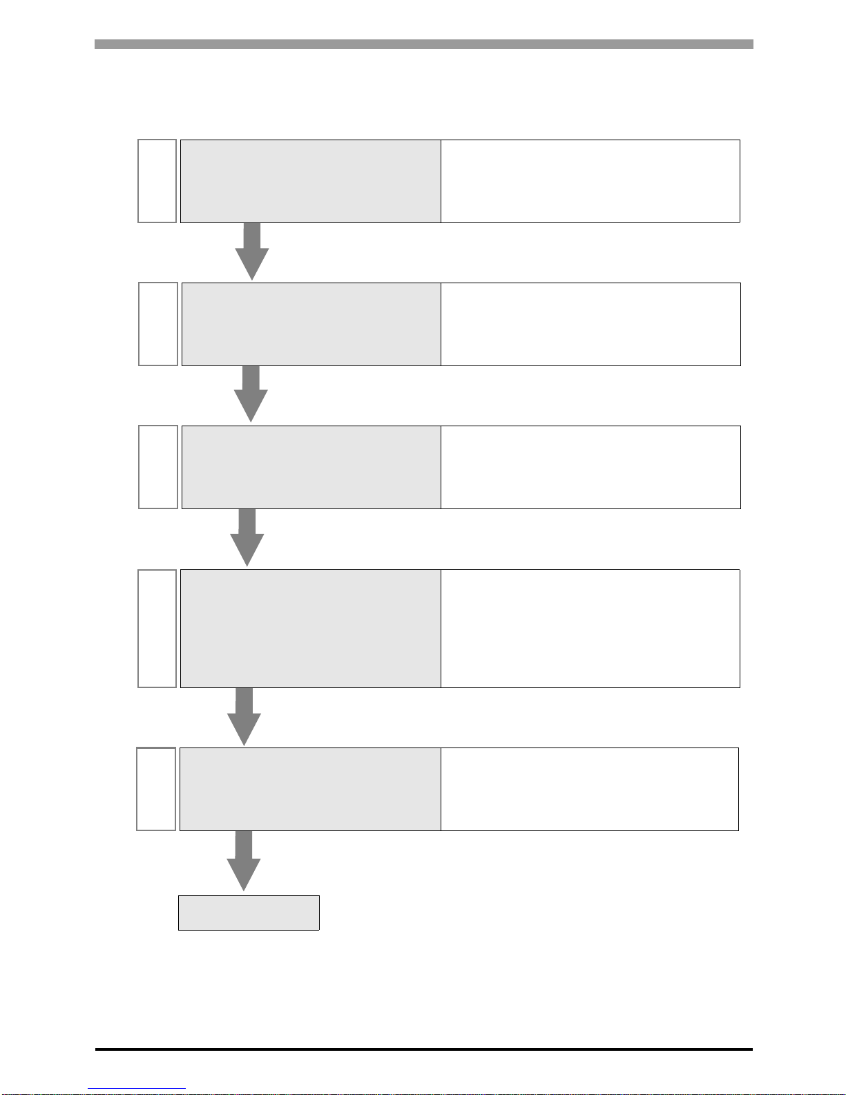
In this manual, the connection procedure is described in the sections identified below:
1
System Configuration
This section lists the types of External
Devices and SIO that you can connect.
)"1 System Configuration" (page 3)
2
External Devices Selection
Select a model (series) of the External
Device and its connection method.
)"2 External Devices Selection" (page 9)
3
Communication Settings
This section shows setting examples for
communicating between the Display and
the External Device.
)"3 Communication Settings" (page 10)
4
Setup Items
This section describes communication
setup items on the Display.
Set the Display’s communication settings
in GP Pro-EX or in offline mode.
)"4 Setup Items" (page 58)
5
Cable Diagrams
This section shows cables and adapters
for connecting the Display and the
External Device.
)"5 Cable Diagrams" (page 62)
Operation

FREQROL Inverter Driver
GP-Pro EX Device/PLC Connection Manual
3
1 System Configuration
The following table lists system configurations for connecting Mitsubishi Electric Corporation External Devices
and the Display.
• If problems such as communication interruptions due to a disconnection of the signal
wire or malfunction of the Display cannot be detected on the inverter side, implement
a precautionary measure by using the inverter’s communication retry function or
communication check functi on . Refer to your External Device manual for details.
• Do not reset the inverter while communication is enabled. This may cause
malfunction. Prior to resetting the inverter, take the Display offline.
Series Inverter
*1
Link I/F SIO Type Setting Example Cable Diagram
FR-A700
FR-A720-K
FR-A740-K
PU connector on
the Inverter
RS-422/485
(4 wire )
"Setting Example 1"
(page 10)
" Cable Diagram 1"
(page 62)
RS-485 terminal
on the Inverter
RS-422/485
(4 wire )
"Setting Example 2"
(page 12)
" Cable Diagram 2"
(page 66)
RS-422/485
(2 wire)
"Setting Example 3"
(page 14)
" Cable Diagram 3"
(page 72)
FR-A701 FR-A721-K
PU connector on
the Inverter
RS-422/485
(4 wire )
"Setting Example 1"
(page 10)
" Cable Diagram 1"
(page 62)
RS-485 terminal
on the Inverter
RS-422/485
(4 wire )
"Setting Example 2"
(page 12)
" Cable Diagram 2"
(page 66)
RS-422/485
(2 wire)
"Setting Example 3"
(page 14)
" Cable Diagram 3"
(page 72)
FR-F700
FR-F720-K
FR-F740-K
PU connector on
the Inverter
RS-422/485
(4 wire )
"Setting Example 4"
(page 16)
" Cable Diagram 1"
(page 62)
RS-485 terminal
on the Inverter
RS-422/485
(4 wire )
"Setting Example 5"
(page 18)
" Cable Diagram 2"
(page 66)
RS-422/485
(2 wire)
"Setting Example 6"
(page 20)
" Cable Diagram 3"
(page 72)
FR-E700
FR-E720-K
FR-E740-K
FR-E720S-K
FR-E710W-K
PU connector on
the Inverter
RS-422/485
(4 wire )
"Setting Example 7"
(page 22)
" Cable Diagram 4"
(page 81)
*2
RS-422/485
(2 wire)
"Setting Example 8"
(page 24)
" Cable Diagram 5"
(page 92)
RS-485 terminal
on FR-E7TR
RS-422/485
(4 wire )
"Setting Example 7"
(page 22)
" Cable Diagram 8"
(page 124)
RS-422/485
(2 wire)
"Setting Example 8"
(page 24)
" Cable Diagram 9"
(page 130)
FR-V500
FR-V520-K
FR-V540-K
PU connector on
the Inverter
RS-422/485
(4 wire )
"Setting Example 9"
(page 26)
" Cable Diagram 4"
(page 81)
*2
T erminal on
FR-A5NR
RS-422/485
(4 wire )
"Setting Example
10" (page 28)
" Cable Diagram 7"
(page 118)

FREQROL Inverter Driver
GP-Pro EX Device/PLC Connection Manual
4
FR-V500L
FR-V520L-K
FR-V540L-K
PU connector on
the Inverter
RS-422/485
(4 wire )
"Setting Example 9"
(page 26)
" Cable Diagram 4"
(page 81)
*2
T erminal on
FR-A5NR
RS-422/485
(4 wire )
"Setting Example
10" (page 28)
" Cable Diagram 7"
(page 118)
FR-A500
FR-A520-K
FR-A540-K
PU connector on
the Inverter
RS-422/485
(4 wire )
"Setting Example
11" (page 30)
" Cable Diagram 4"
(page 81)
*2
T erminal on
FR-A5NR
RS-422/485
(4 wire )
"Setting Example
12" (page 32)
" Cable Diagram 7"
(page 118)
FR-A500L
FR-A520L-K
FR-A540L-K
PU connector on
the Inverter
RS-422/485
(4 wire )
"Setting Example
11" (page 30)
" Cable Diagram 4"
(page 81)
*2
T erminal on
FR-A5NR
RS-422/485
(4 wire )
"Setting Example
12" (page 32)
" Cable Diagram 7"
(page 118)
FR-F500
FR-F520-K
FR-F540-K
PU connector on
the Inverter
RS-422/485
(4 wire )
"Setting Example
13" (page 34)
" Cable Diagram 4"
(page 81)
*2
T erminal on
FR-A5NR
RS-422/485
(4 wire )
"Setting Example
14" (page 36)
" Cable Diagram 7"
(page 118)
FR-F500L
FR-F520L-K
FR-F540L-K
PU connector on
the Inverter
RS-422/485
(4 wire )
"Setting Example
13" (page 34)
" Cable Diagram 4"
(page 81)
*2
T erminal on
FR-A5NR
RS-422/485
(4 wire )
"Setting Example
14" (page 36)
" Cable Diagram 7"
(page 118)
FR-E500
FR-E520-K
FR-E540-K
FR-E520S-K
FR-E510W-K
PU connector on
the Inverter
RS-422/485
(4 wire )
"Setting Example
15" (page 38)
" Cable Diagram 4"
(page 81)
*2
FR-C500 FR-C520-K
PU connector on
the Inverter
RS-422/485
(4 wire )
"Setting Example
16" (page 40)
" Cable Diagram 4"
(page 81)
*2
FR-S500
FR-S520-K(-R)(-C)
FR-S540-K(-R)
FR-S520S-K(-R)
FR-S510W-K(-R)
FR-S520E-K(-C)
FR-S540E-K
FR-S520SE-K
FR-S510WE-K
RS-485
connector on the
Inverter
RS-422/485
(4 wire )
"Setting Example
17" (page 42)
" Cable Diagram 4"
(page 81)
*2
FR-S520E-K-NMR
RS-485 terminal
on the Inverter
RS-422/485
(2 wire)
"Setting Example
18" (page 44)
" Cable Diagram 6"
(page 109)
FR-F500J
FR-F520J-K(F)
FR-F540J-K(F)
RS-485
connector on the
Inverter
RS-422/485
(4 wire )
"Setting Example
19" (page 46)
" Cable Diagram 4"
(page 81)
*2
FRB,B3(A500)
FR-B-K
FR-B3-(N)(H)K
PU connector on
the Inverter
RS-422/485
(4 wire )
"Setting Example
20" (page 48)
" Cable Diagram 4"
(page 81)
*2
T erminal on
FR-A5NR
RS-422/485
(4 wire )
"Setting Example
21" (page 50)
" Cable Diagram 7"
(page 118)
Series Inverter
*1
Link I/F SIO Type Setting Example Cable Diagram

FREQROL Inverter Driver
GP-Pro EX Device/PLC Connection Manual
5
FRB,B3(A700)
FR-B-K
FR-B3-(N)(H)K
PU connector on
the Inverter
RS-422/485
(4 wire )
"Setting Example
22" (page 52)
" Cable Diagram 1"
(page 62)
RS-485 terminal
on the Inverter
RS-422/485
(4 wire )
"Setting Example
23" (page 54)
" Cable Diagram 2"
(page 66)
RS-422/485
(2 wire)
"Setting Example
24" (page 56)
" Cable Diagram 3"
(page 72)
*1 varies depending on each inverter’s capacity.
*2 Cable Diagram 1 can be used for 1:1 Connection.
Series Inverter
*1
Link I/F SIO Type Setting Example Cable Diagram
FREQROL Inverter Driver
GP-Pro EX Device/PLC Connection Manual
6
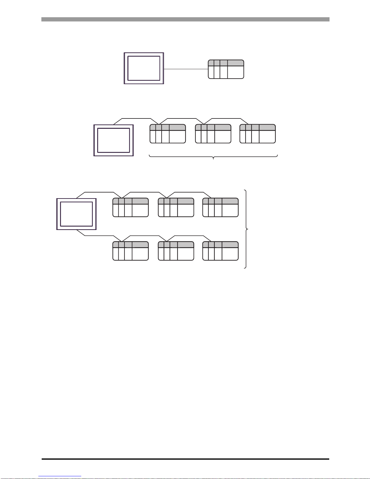
Connection Configuration
• 1:1 Connection
• 1:n Connection
Display
External Device
Display
External Device External Device External Device
Maximum number of External Devices: 16
Display
External Device External Device External Device
External Device External Device External Device
Maximum number of
External Devices: 32
FREQROL Inverter Driver
GP-Pro EX Device/PLC Connection Manual
7
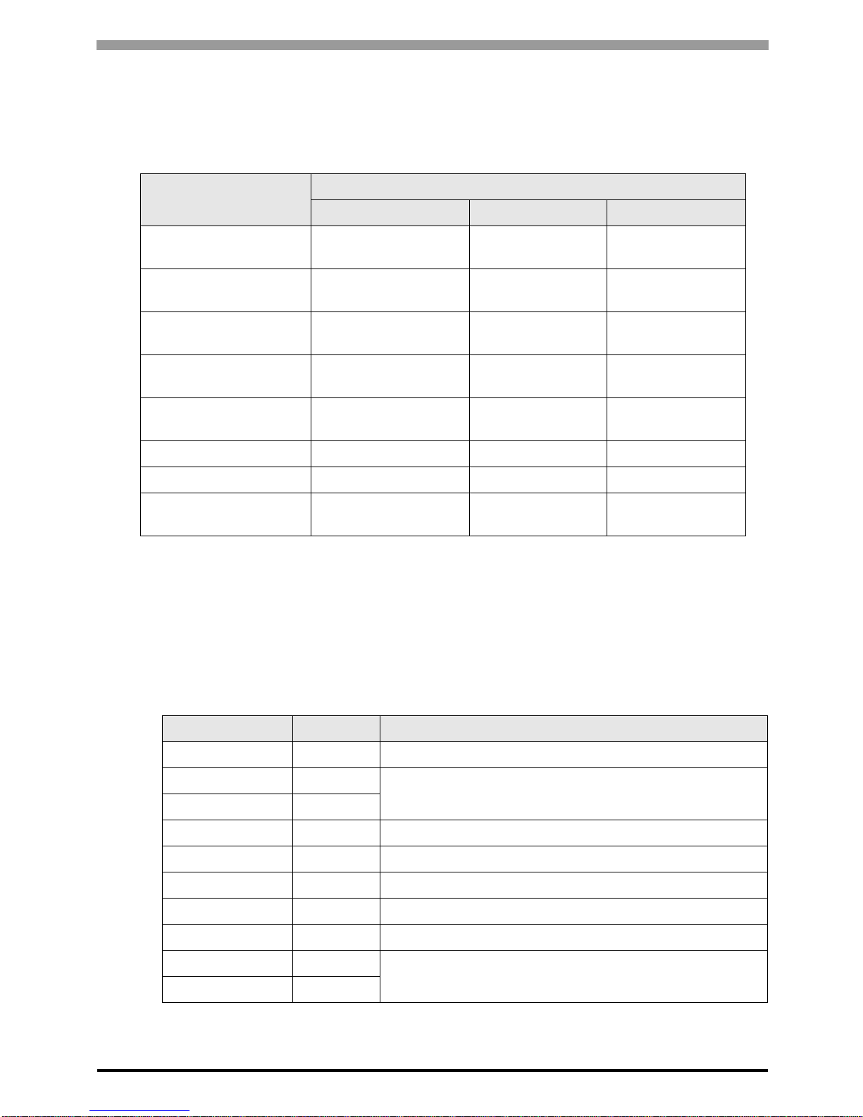
IPC COM Port
When connecting IPC with an External Device, the COM port used depends on the series and SIO type. Please
refer to the IPC manual for details.
Usable port
DIP Switch setting: RS-232C
Series
Usable Port
RS-232C RS-422/485(4 wire) RS-422/485(2 wire)
PS-2000B
COM1
*1
, COM2,
COM3
*1
, COM4
*1 The RI/5V can be switched. Use the IPC’s switch to change if necessary.
--
PS-3450A, PS-3451A,
PS3000-BA, PS3001-BD
COM1, COM2
*1*2
COM2
*1*2
COM2
*1*2
PS-3650A (T41 model),
PS-3651A (T41 model)
COM1
*1
--
PS-3650A (T42 model),
PS-3651A (T42 model)
COM1
*1*2
, COM2 COM1
*1*2
COM1
*1*2
PS-3700A (Pentium®4-M)
PS-3710A
COM1*1, COM2*1,
COM3*2, COM4
*2 Set up the SIO type with the DIP Switch. Please set up as follows according to SIO type to be used.
COM3
*2
COM3
*2
PS-3711A COM1*1, COM2
*2
COM2
*2
COM2
*2
PS4000
*3
*3 When making communication between an External Device and COM port on the Expansion slot,
only RS-232C is supported. However, ER (DTR/CTS) control cannot be executed because of the
specification of COM port.
For connection with External Device, use user-created cables and disable Pin Nos. 1, 4, 6 and 9.
Please refer to the IPC manual for details of pin layout.
COM1, COM2 - -
PL3000
COM1
*1*2
, COM2*1,
COM3, COM4
COM1
*1*2
COM1
*1*2
DIP Switch Setting Description
1OFF
*1
*1 When using PS-3450A, PS-3451A, PS3000-BA and PS3001-BD, turn ON the set value.
Reserved (always OFF)
2OFF
SIO type: RS-232C
3OFF
4 OFF Output mode of SD (TXD) data: Always output
5 OFF Terminal resistance (220Ω) insertion to SD (TXD): None
6 OFF Terminal resistance (220Ω) insertion to RD (RXD): None
7 OFF Short-circuit of SDA (TXA) and RDA (RXA): Not available
8 OFF Short-circuit of SDB (TXB) and RDB (RXB): Not available
9OFF
RS (RTS) Auto control mode: Disabled
10 OFF

FREQROL Inverter Driver
GP-Pro EX Device/PLC Connection Manual
8
DIP Switch setting: RS-422/485 (4 wire)
DIP Switch setting: RS-422/485 (2 wire)
DIP Switch Setting Description
1 OFF Reserved (always OFF)
2ON
SIO type: RS-422/485
3ON
4 OFF Output mode of SD (TXD) data: Always output
5 OFF Terminal resistance (220Ω) insertion to SD (TXD): None
6 OFF Terminal resistance (220Ω) insertion to RD (RXD): None
7 OFF Short-circuit of SDA (TXA) and RDA (RXA): Not available
8 OFF Short-circuit of SDB (TXB) and RDB (RXB): Not available
9OFF
RS (RTS) Auto control mode: Disabled
10 OFF
DIP Switch Setting Description
1 OFF Reserved (always OFF)
2ON
SIO type: RS-422/485
3ON
4 OFF Output mode of SD (TXD) data: Always output
5 OFF Terminal resistance (220Ω) insertion to SD (TXD): None
6 OFF Terminal resistance (220Ω) insertion to RD (RXD): None
7 ON Short-circuit of SDA (TXA) and RDA (RXA): Available
8 ON Short-circuit of SDB (TXB) and RDB (RXB): Available
9ON
RS (RTS) Auto control mode: Enabled
10 ON
FREQROL Inverter Driver
GP-Pro EX Device/PLC Connection Manual
9
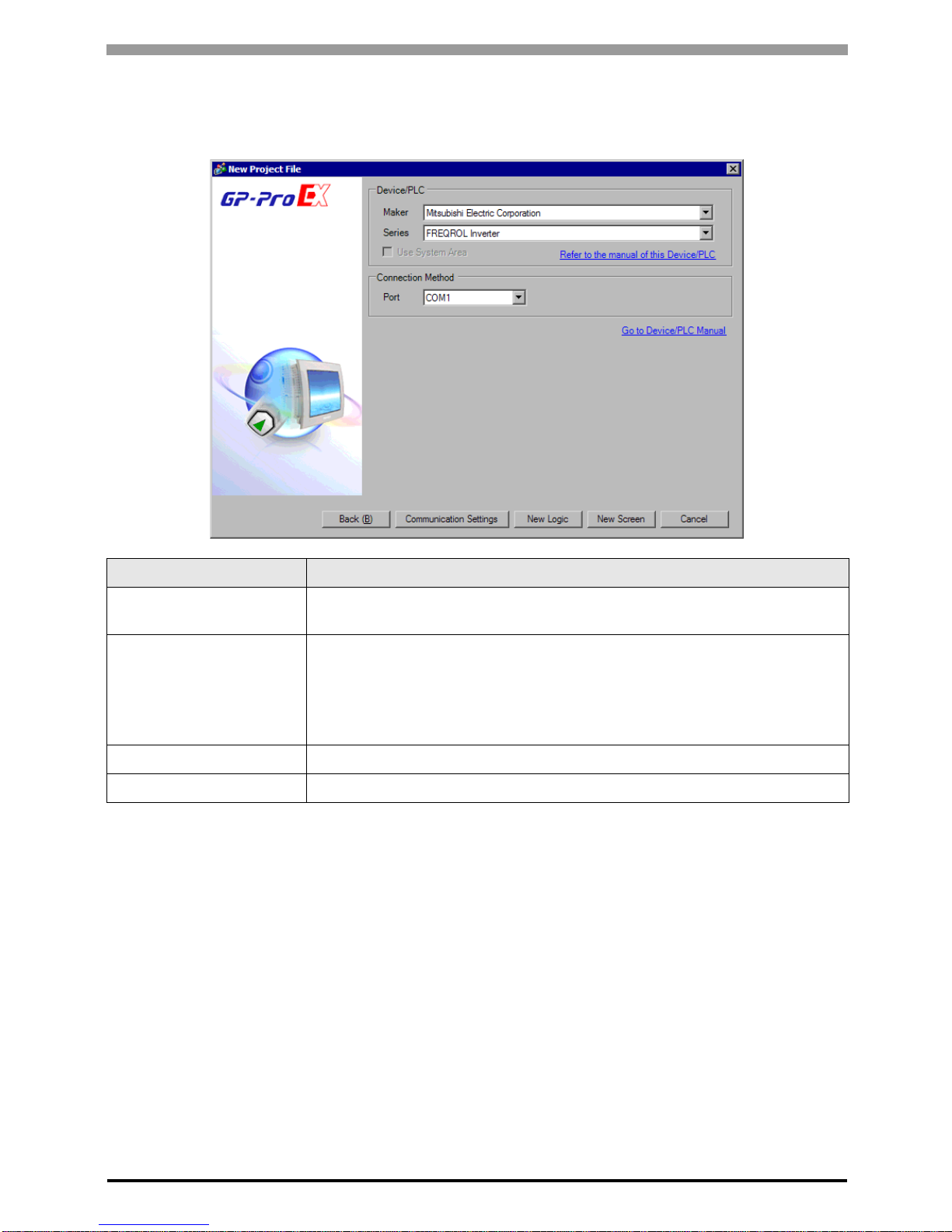
2 External Devices Selection
Select the External Device to be connected to the Display .
Setup Items Setup Description
Maker
Select the maker of the External Device to be connected. Select "Mitsubishi Electric
Corporation".
Series
Select a model (series) of the External Device to be connected and connection method.
Select "FREQROL Inverter".
In System configuration, check to make sure the external device to which you are
connecting is supported in "FREQROL Inverter".
)"1 System Configuration" (page 3)
Use System Area Not available for this driver.
Port Select the Display port to be connected to the External Device.
FREQROL Inverter Driver
GP-Pro EX Device/PLC Connection Manual
10
3 Communication Settings
This section provides examples of communication settings recommended by Pro-face for the Display and the
External Device.
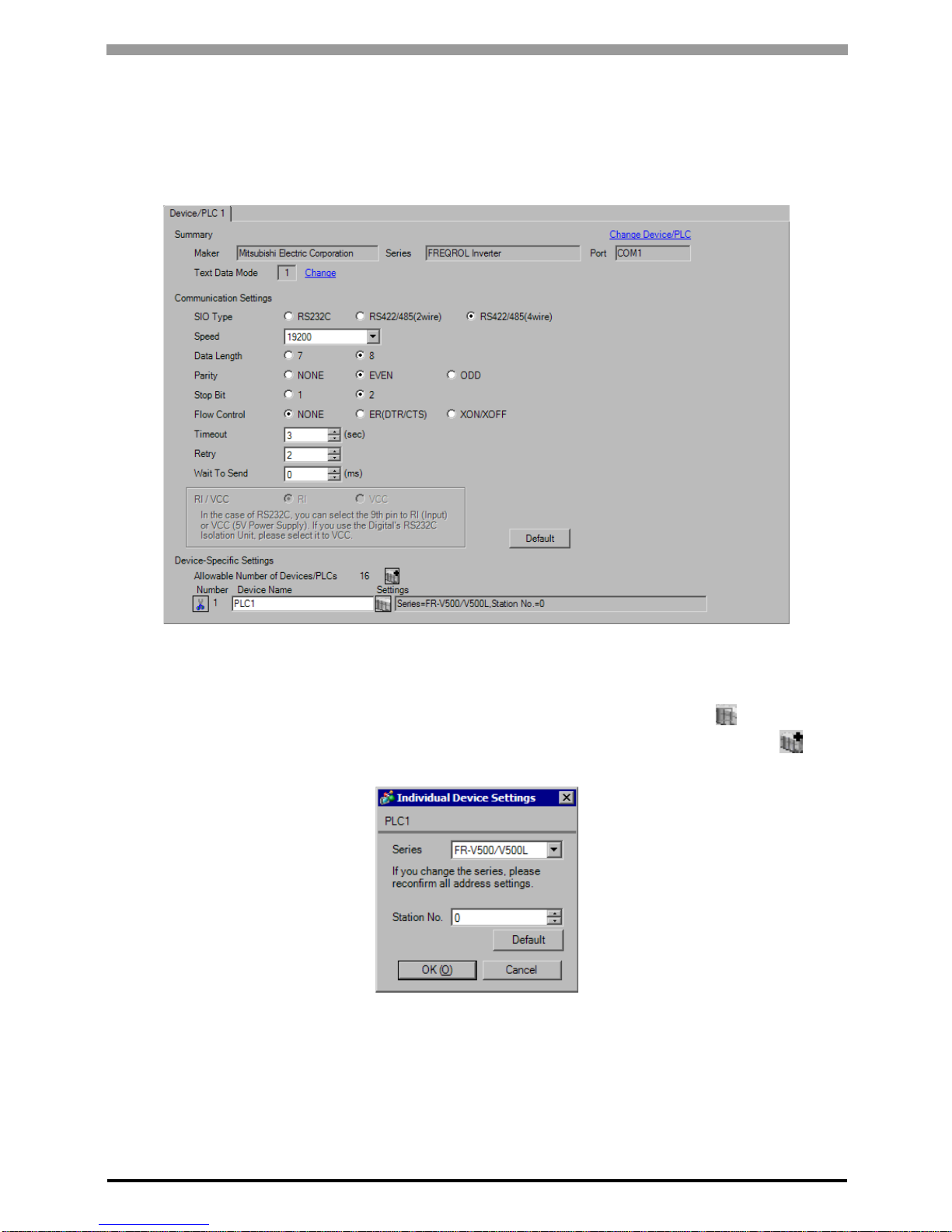
3.1 Setting Example 1
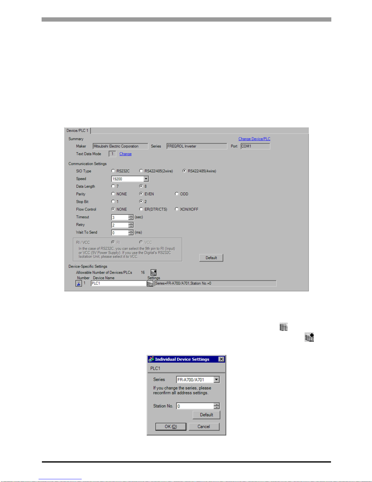
GP Pro-EX Settings
Communication Settings
T o display the setup screen, from the [System Settings] workspace, select [Device/PLC].
Device Setting
To display the [Individual Device Settings] dialog box, select the external device and click [Settings] from
[Device-Specific Settings] in the [Device/PLC] window. To connect multiple External Devices, click from
[Device-Specific Settings] in the [Device/PLC] window to add another External Device.
FREQROL Inverter Driver
GP-Pro EX Device/PLC Connection Manual
11
External Device Settings
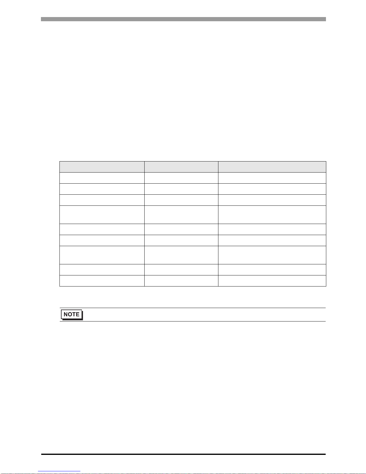
Use the PU/EXT key, MODE key, M dial and SET key in the operation panel of the CPU unit for External Device
communication settings.
Refer to your External Device manual for details.
1 Turn ON the power supply.
2 Press PU/EXT key to select the PU operation mode.
3 Press MODE key to select the parameter setting mode.
4 Display the setting parameter number with M dial.
5 Press SET key to display the current setting value.
6 Set the setting value with M dial.
7 Press SET key to confirm the setting value.
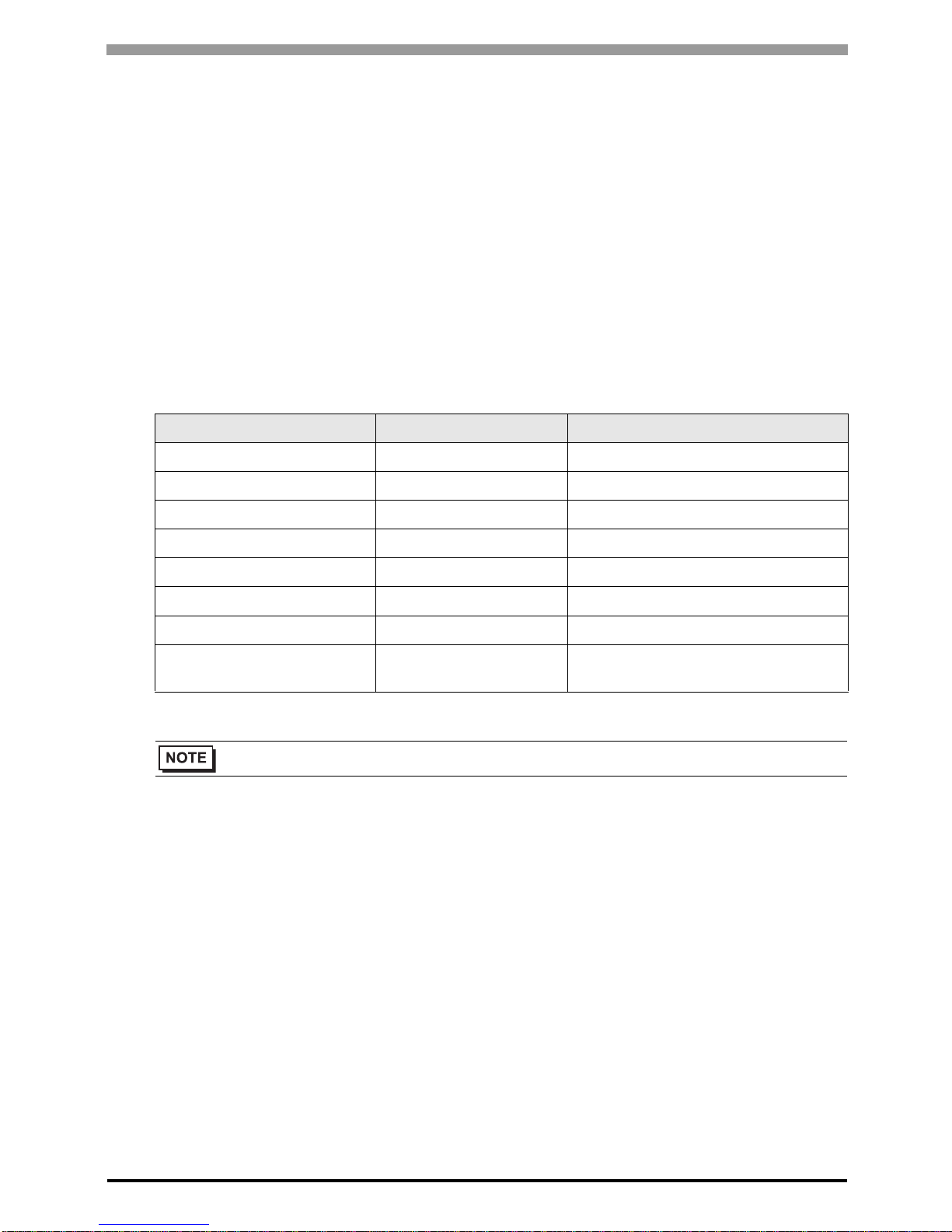
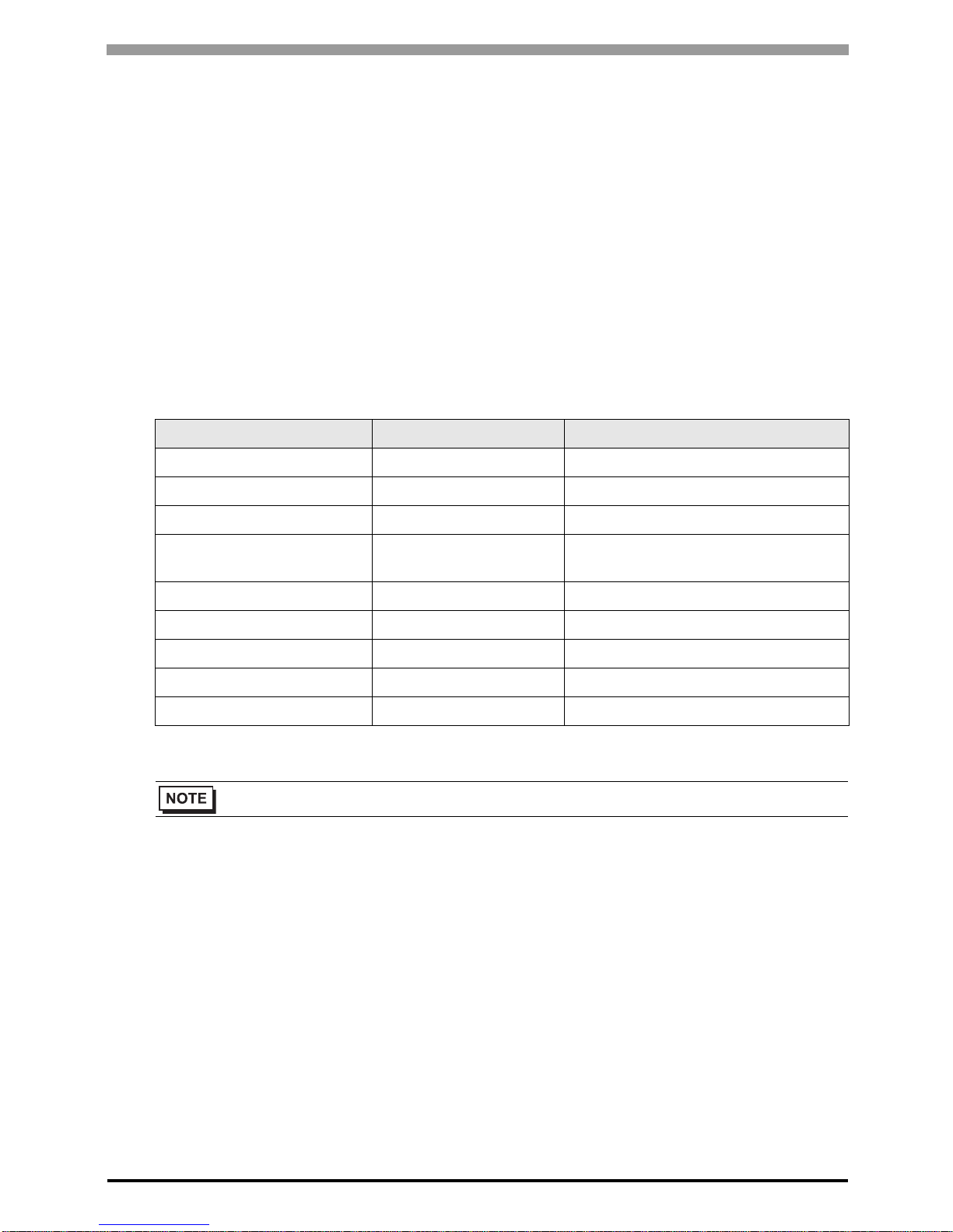
Setting Parameter Number Setting Value Setup Description
117 0 PU communication station number
118 192 PU communication speed
119 1 PU communication stop bit length
120 2 PU communication parity check
121 1 Number of PU communication retries
122 Any Except 0 PU communication check time interval
123 9999 PU communication waiting time setting
124 1
PU communication CR/LF presence/
absence selection
• Always restart the Eternal Device after changing parameters.

FREQROL Inverter Driver
GP-Pro EX Device/PLC Connection Manual
12
3.2 Setting Example 2
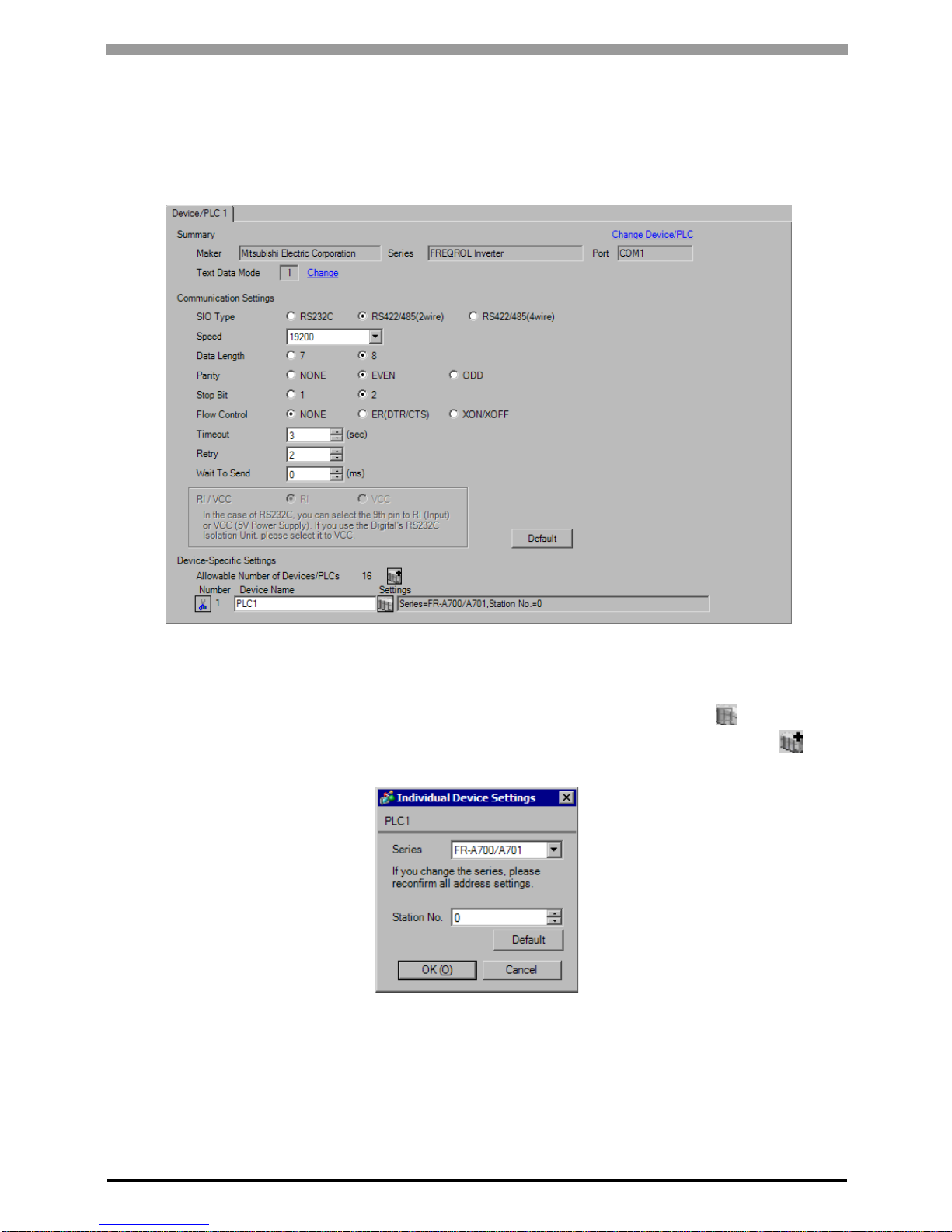
GP Pro-EX Settings
Communication Settings
T o display the setup screen, from the [System Settings] workspace, select [Device/PLC].
Device Setting
To display the [Individual Device Settings] dialog box, select the external device and click [Settings] from
[Device-Specific Settings] in the [Device/PLC] window. To connect multiple External Devices, click from
[Device-Specific Settings] in the [Device/PLC] window to add another External Device.
FREQROL Inverter Driver
GP-Pro EX Device/PLC Connection Manual
13
External Device Settings
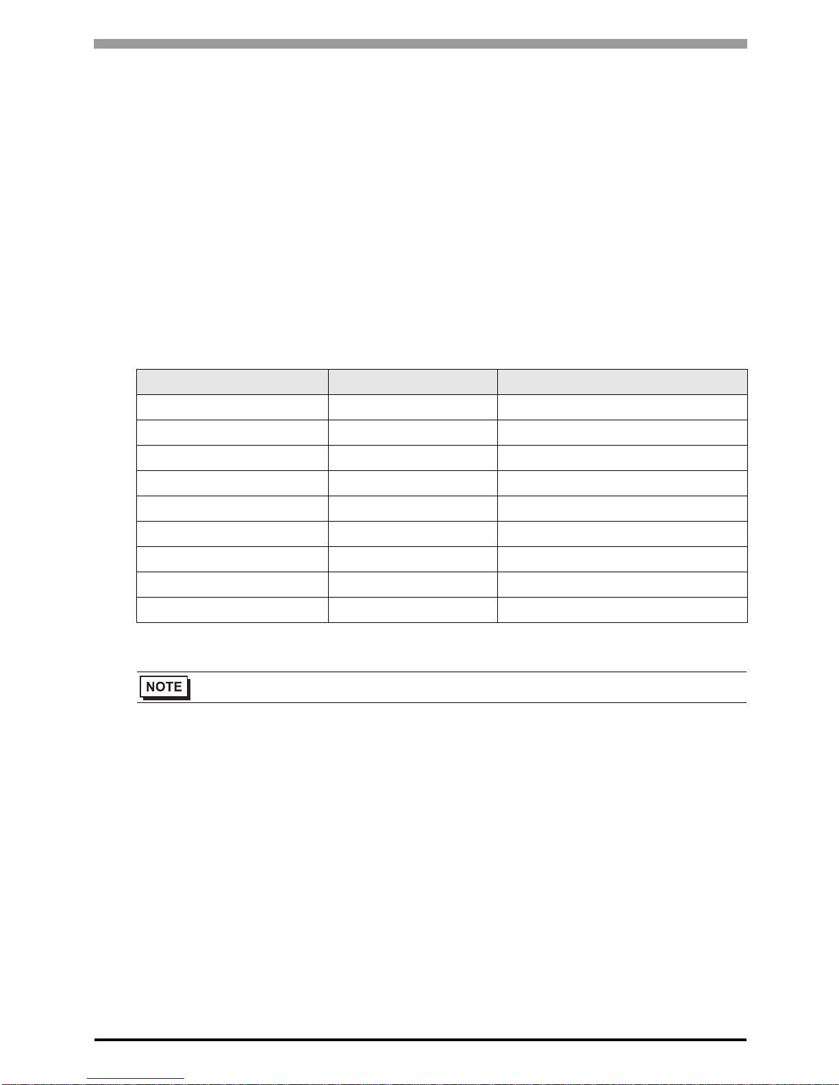
Use the PU/EXT key, MODE key, M dial and SET key in the operation panel of the CPU unit for External Device
communication settings.
Refer to your External Device manual for details.
1 Turn ON the power supply.
2 Press PU/EXT key to select the PU operation mode.
3 Press MODE key to select the parameter setting mode.
4 Display the setting parameter number with M dial.
5 Press SET key to display the current setting value.
6 Set the setting value with M dial.
7 Press SET key to confirm the setting value.
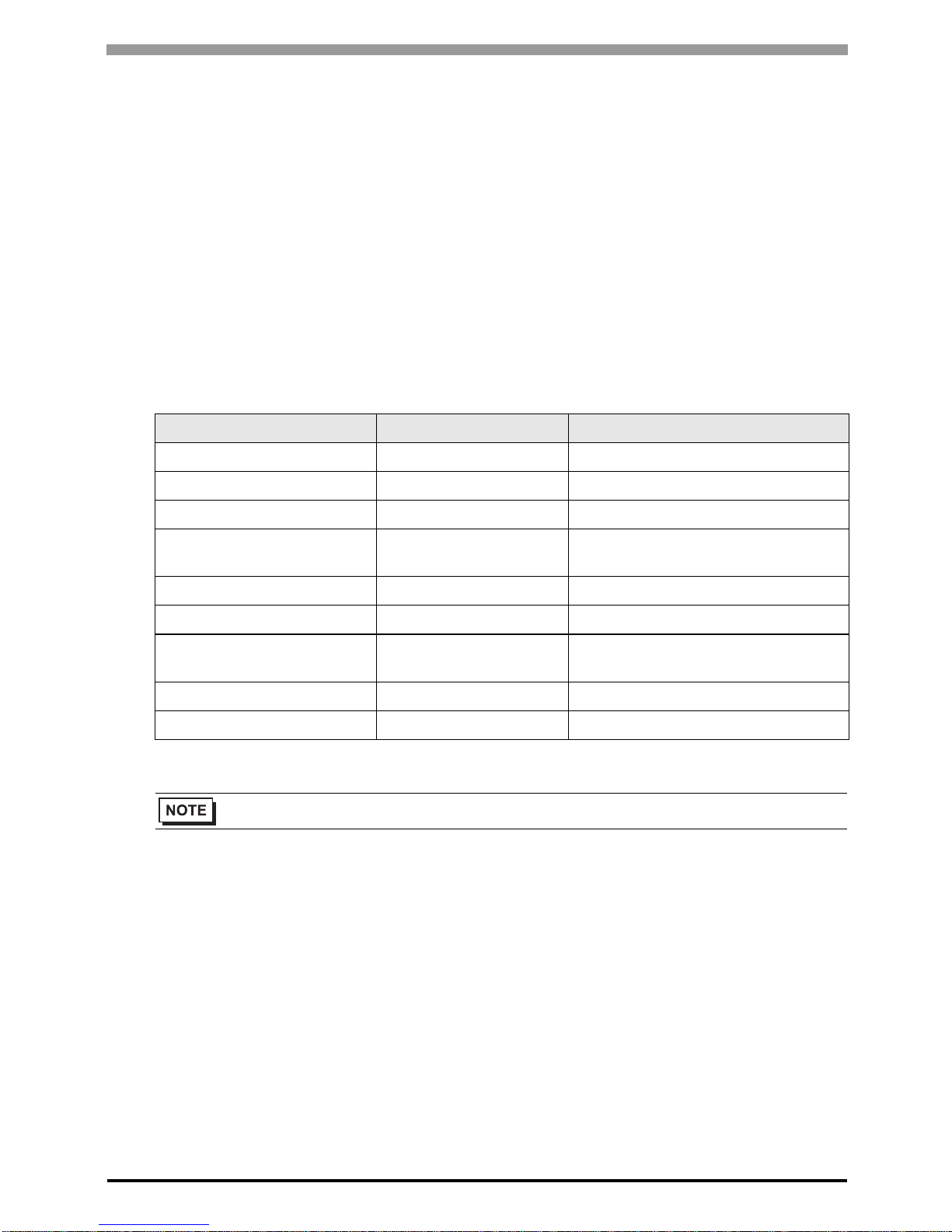
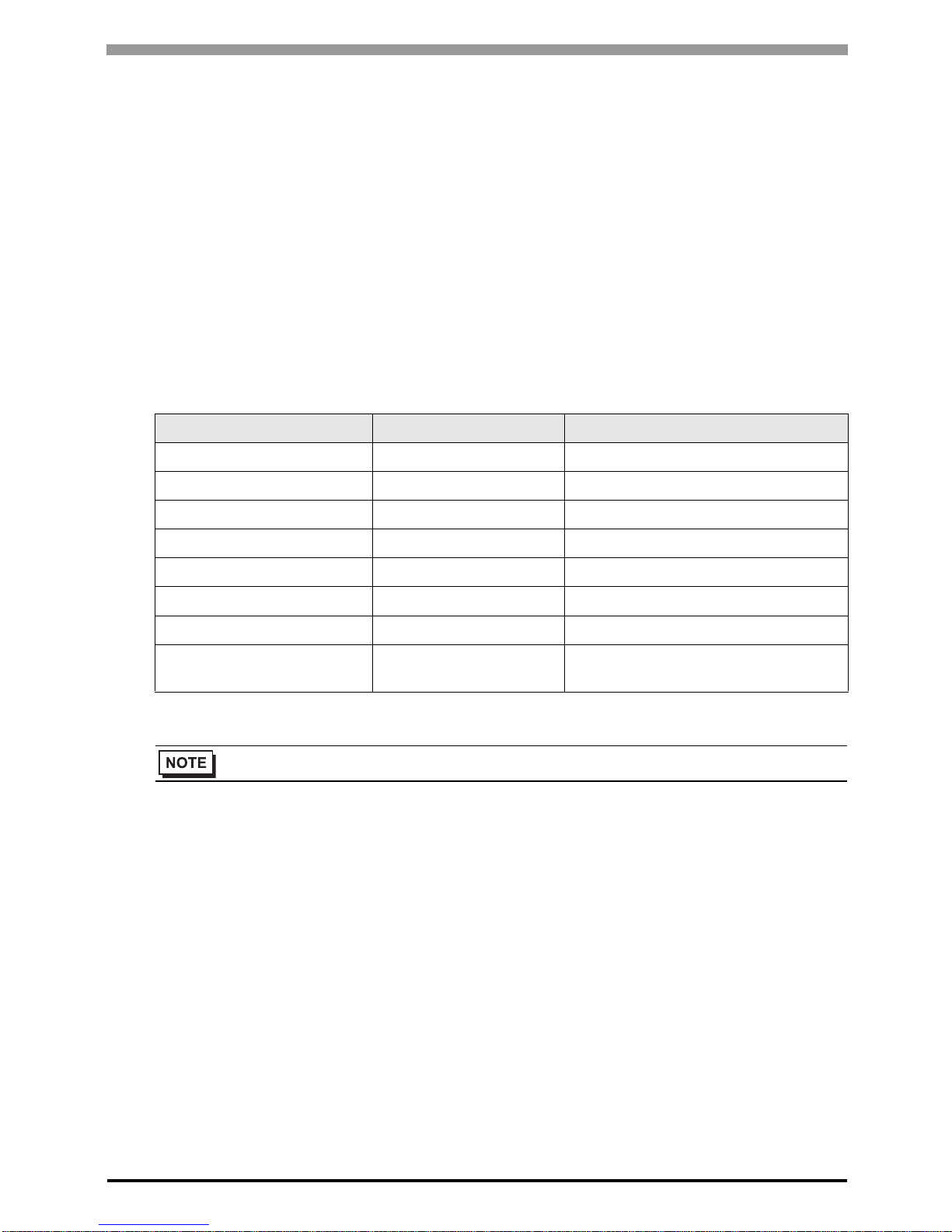
Setting Parameter Number Setting Value Setup Description
331 0 RS-485 communication station
332 192 RS-485 communication speed
333 1 RS-485 communication stop bit length
334 2
RS-485 communication parity check
selection
335 1 RS-485 communication retry count
336 Any Except 0 RS-485 communication check time interval
337 9999
RS-485 communication waiting time
setting
341 1 RS-485 communication CR/LF selection
549 0 Protocol selection
• Always restart the Eternal Device after changing parameters.
FREQROL Inverter Driver
GP-Pro EX Device/PLC Connection Manual
14
3.3 Setting Example 3
GP Pro-EX Settings
Communication Settings
T o display the setup screen, from the [System Settings] workspace, select [Device/PLC].
Device Setting
To display the [Individual Device Settings] dialog box, select the external device and click [Settings] from
[Device-Specific Settings] in the [Device/PLC] window. To connect multiple External Devices, click from
[Device-Specific Settings] in the [Device/PLC] window to add another External Device.
FREQROL Inverter Driver
GP-Pro EX Device/PLC Connection Manual
15
External Device Settings
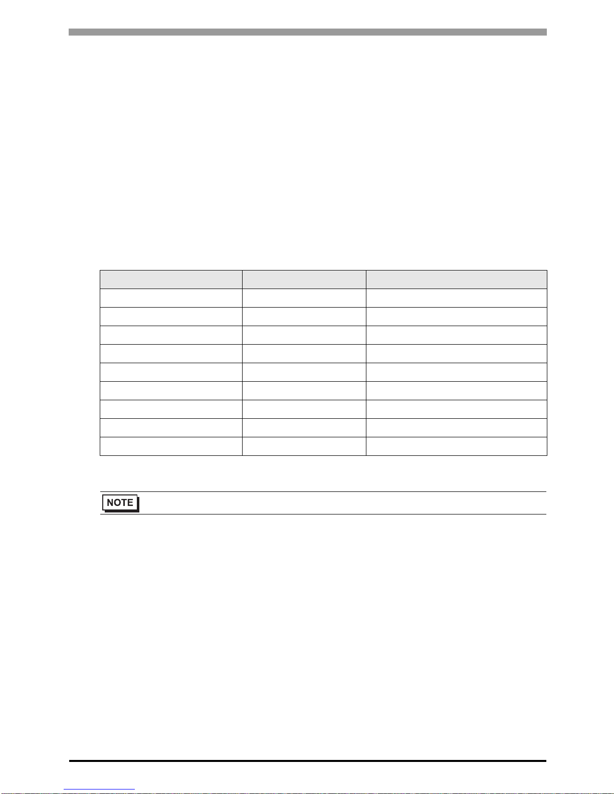
Use the PU/EXT key, MODE key, M dial and SET key in the operation panel of the CPU unit for External Device
communication settings.
Refer to your External Device manual for details.
1 Turn ON the power supply.
2 Press PU/EXT key to select the PU operation mode.
3 Press MODE key to select the parameter setting mode.
4 Display the setting parameter number with M dial.
5 Press SET key to display the current setting value.
6 Set the setting value with M dial.
7 Press SET key to confirm the setting value.
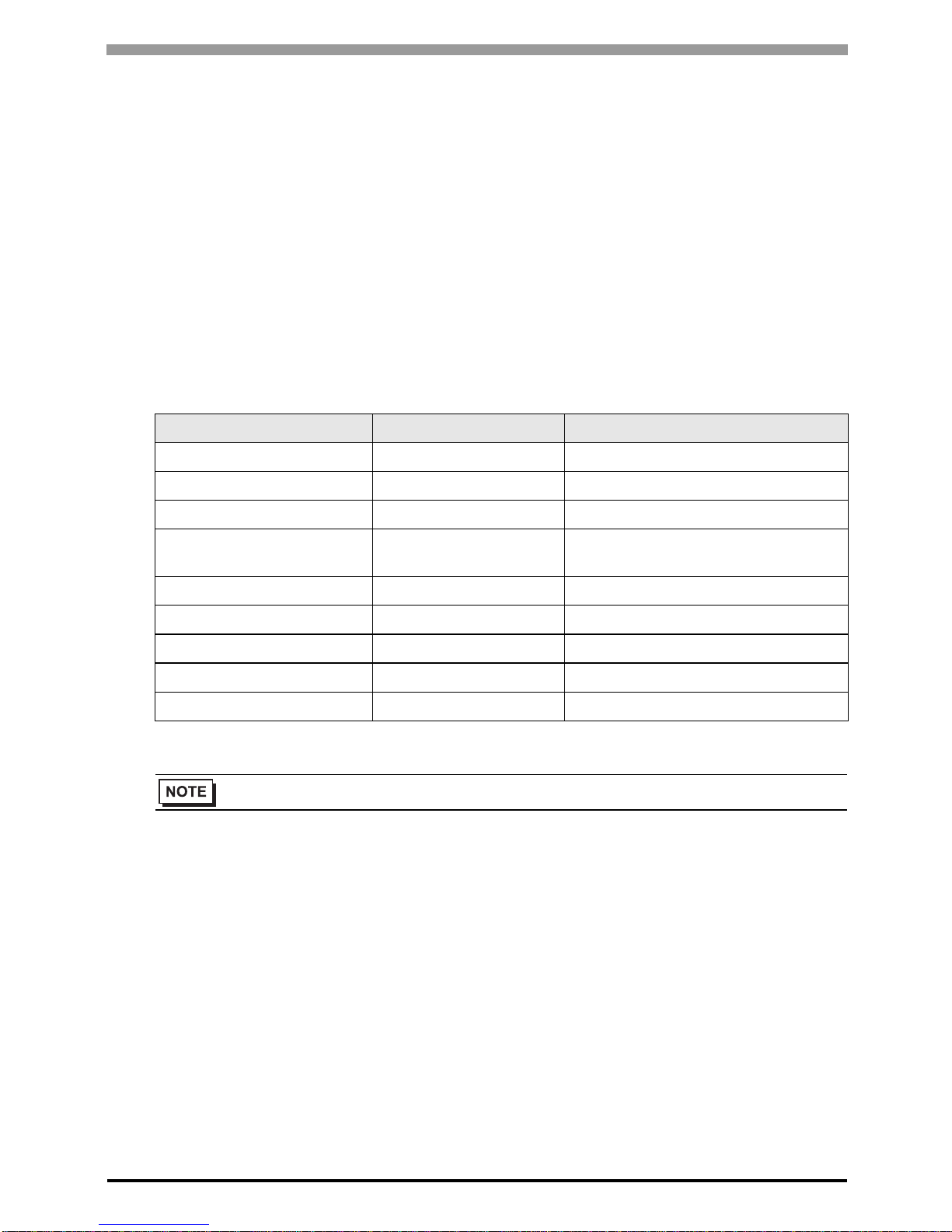
Setting Parameter Number Setting Value Setup Description
331 0 RS-485 communication station
332 192 RS-485 communication speed
333 1 RS-485 communication stop bit length
334 2
RS-485 communication parity check
selection
335 1 RS-485 communication retry count
336 Any Except 0 RS-485 communication check time interval
337 9999 RS-485 communication waiting time setting
341 1 RS-485 communication CR/LF selection
549 0 Protocol selection
• Always restart the Eternal Device after changing parameters.

FREQROL Inverter Driver
GP-Pro EX Device/PLC Connection Manual
16
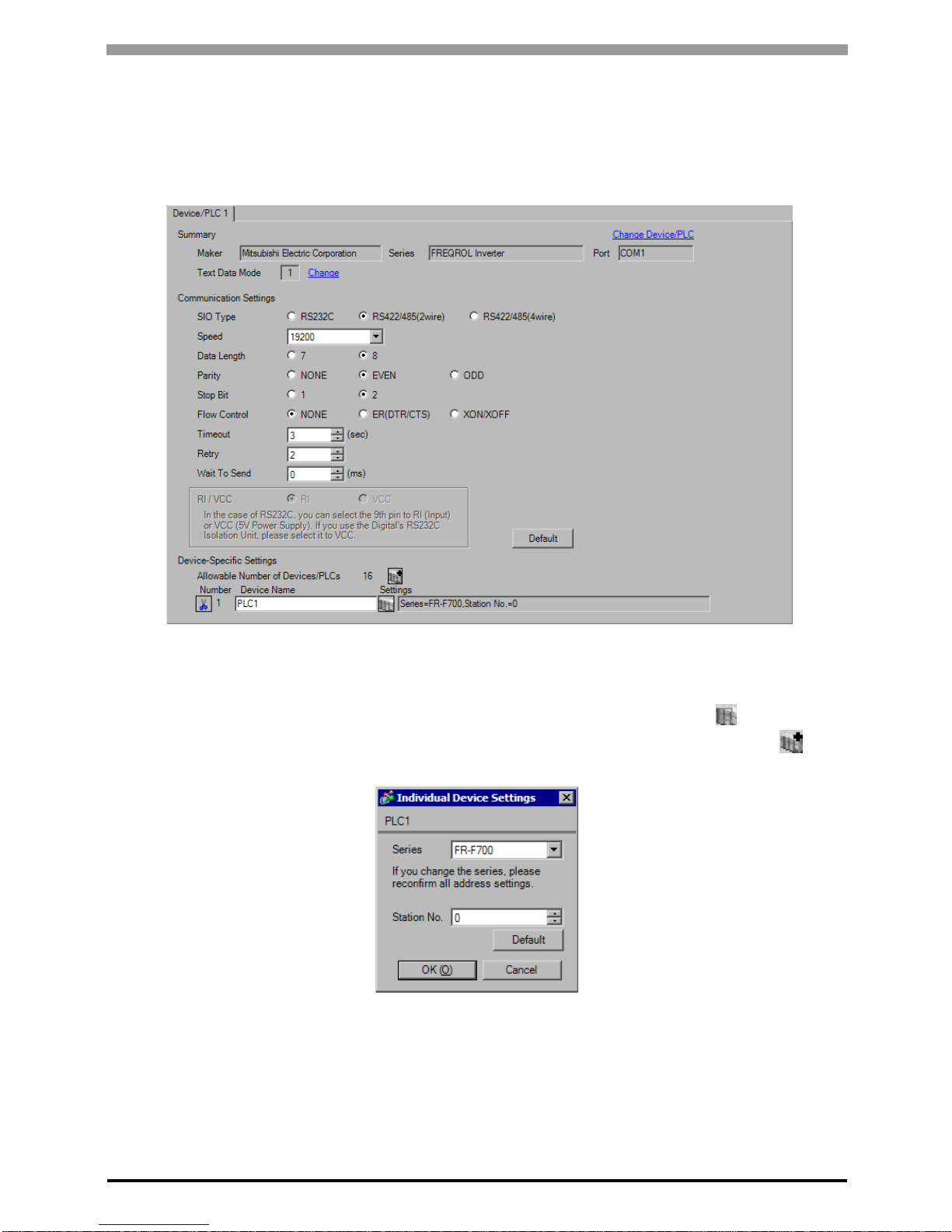
3.4 Setting Example 4
GP Pro-EX Settings
Communication Settings
T o display the setup screen, from the [System Settings] workspace, select [Device/PLC].
Device Setting
To display the [Individual Device Settings] dialog box, select the external device and click [Settings] from
[Device-Specific Settings] in the [Device/PLC] window. To connect multiple External Devices, click from
[Device-Specific Settings] in the [Device/PLC] window to add another External Device.
FREQROL Inverter Driver
GP-Pro EX Device/PLC Connection Manual
17
External Device Settings
Use the PU/EXT key, MODE key, M dial and SET key in the operation panel of the CPU unit for External Device
communication settings.
Refer to your External Device manual for details.
1 Turn ON the power supply.
2 Press PU/EXT key to select the PU operation mode.
3 Press MODE key to select the parameter setting mode.
4 Display the setting parameter number with M dial.
5 Press SET key to display the current setting value.
6 Set the setting value with M dial.
7 Press SET key to confirm the setting value.
Setting Parameter Number Setting Value Setup Description
117 0 PU communication station number
118 192 PU communication speed
119 1 PU communication stop bit length
120 2 PU communication parity check
121 1 Number of PU communication retries
122 Any Except 0 PU communication check time interval
123 9999 PU communication waiting time setting
124 1
PU communication CR/LF presence/
absence selection
• Always restart the Eternal Device after changing parameters.

FREQROL Inverter Driver
GP-Pro EX Device/PLC Connection Manual
18
3.5 Setting Example 5
GP Pro-EX Settings
Communication Settings
T o display the setup screen, from the [System Settings] workspace, select [Device/PLC].
Device Setting
To display the [Individual Device Settings] dialog box, select the external device and click [Settings] from
[Device-Specific Settings] in the [Device/PLC] window. To connect multiple External Devices, click from
[Device-Specific Settings] in the [Device/PLC] window to add another External Device.
FREQROL Inverter Driver
GP-Pro EX Device/PLC Connection Manual
19
External Device Settings
Use the PU/EXT key, MODE key, M dial and SET key in the operation panel of the CPU unit for External Device
communication settings.
Refer to your External Device manual for details.
1 Turn ON the power supply.
2 Press PU/EXT key to select the PU operation mode.
3 Press MODE key to select the parameter setting mode.
4 Display the setting parameter number with M dial.
5 Press SET key to display the current setting value.
6 Set the setting value with M dial.
7 Press SET key to confirm the setting value.
Setting Parameter Number Setting Value Setup Description
331 0 RS-485 communication station
332 192 RS-485 communication speed
333 1 RS-485 communication stop bit length
334 2
RS-485 communication parity check
selection
335 1 RS-485 communication retry count
336 Any Except 0 RS-485 communication check time interval
337 9999 RS-485 communication waiting time setting
341 1 RS-485 communication CR/LF selection
549 0 Protocol selection
• Always restart the Eternal Device after changing parameters.
FREQROL Inverter Driver
GP-Pro EX Device/PLC Connection Manual
20
3.6 Setting Example 6
GP Pro-EX Settings
Communication Settings
T o display the setup screen, from the [System Settings] workspace, select [Device/PLC].
Device Setting
To display the [Individual Device Settings] dialog box, select the external device and click [Settings] from
[Device-Specific Settings] in the [Device/PLC] window. To connect multiple External Devices, click from
[Device-Specific Settings] in the [Device/PLC] window to add another External Device.
FREQROL Inverter Driver
GP-Pro EX Device/PLC Connection Manual
21
External Device Settings
Use the PU/EXT key, MODE key, M dial and SET key in the operation panel of the CPU unit for External Device
communication settings.
Refer to your External Device manual for details.
1 Turn ON the power supply.
2 Press PU/EXT key to select the PU operation mode.
3 Press MODE key to select the parameter setting mode.
4 Display the setting parameter number with M dial.
5 Press SET key to display the current setting value.
6 Set the setting value with M dial.
7 Press SET key to confirm the setting value.
Setting Parameter Number Setting Value Setup Description
331 0 RS-485 communication station
332 192 RS-485 communication speed
333 1 RS-485 communication stop bit length
334 2
RS-485 communication parity check
selection
335 1 RS-485 communication retry count
336 Any Except 0 RS-485 communication check time interval
337 9999
RS-485 communication waiting time
setting
341 1 RS-485 communication CR/LF selection
549 0 Protocol selection
• Always restart the Eternal Device after changing parameters.

FREQROL Inverter Driver
GP-Pro EX Device/PLC Connection Manual
22
3.7 Setting Example 7
GP Pro-EX Settings
Communication Settings
T o display the setup screen, from the [System Settings] workspace, select [Device/PLC].
Device Setting
To display the [Individual Device Settings] dialog box, select the external device and click [Settings] from
[Device-Specific Settings] in the [Device/PLC] window. To connect multiple External Devices, click from
[Device-Specific Settings] in the [Device/PLC] window to add another External Device.
FREQROL Inverter Driver
GP-Pro EX Device/PLC Connection Manual
23
External Device Settings
Use the PU/EXT key, MODE key, M dial and SET key in the operation panel of the CPU unit for External Device
communication settings.
Refer to your External Device manual for details.
1 Turn ON the power supply.
2 Press PU/EXT key to select the PU operation mode.
3 Press MODE key to select the parameter setting mode.
4 Display the setting parameter number with M dial.
5 Press SET key to display the current setting value.
6 Set the setting value with M dial.
7 Press SET key to confirm the setting value.
Setting Parameter Number Setting Value Setup Description
117 0 PU communication station number
118 192 PU communication speed
119 1 PU communication stop bit length
120 2 PU communication parity check
121 1 Number of PU communication retries
122 Any Except 0 PU communication check time interval
123 9999 PU communication waiting time setting
124 1 PU communication CR/LF selection
549 0 Protocol selection
• Always restart the Eternal Device after changing parameters.

FREQROL Inverter Driver
GP-Pro EX Device/PLC Connection Manual
24
3.8 Setting Example 8
GP Pro-EX Settings
Communication Settings
T o display the setup screen, from the [System Settings] workspace, select [Device/PLC].
Device Setting
To display the [Individual Device Settings] dialog box, select the external device and click [Settings] from
[Device-Specific Settings] in the [Device/PLC] window. To connect multiple External Devices, click from
[Device-Specific Settings] in the [Device/PLC] window to add another External Device.
FREQROL Inverter Driver
GP-Pro EX Device/PLC Connection Manual
25
External Device Settings
Use the PU/EXT key, MODE key, M dial and SET key in the operation panel of the CPU unit for External Device
communication settings.
Refer to your External Device manual for details.
1 Turn ON the power supply.
2 Press PU/EXT key to select the PU operation mode.
3 Press MODE key to select the parameter setting mode.
4 Display the setting parameter number with M dial.
5 Press SET key to display the current setting value.
6 Set the setting value with M dial.
7 Press SET key to confirm the setting value.
Setting Parameter Number Setting Value Setup Description
117 0 PU communication station number
118 192 PU communication speed
119 1 PU communication stop bit length
120 2 PU communication parity check
121 1 Number of PU communication retries
122 Any Except 0 PU communication check time interval
123 9999 PU communication waiting time setting
124 1 PU communication CR/LF selection
549 0 Protocol selection
• Always restart the Eternal Device after changing parameters.
FREQROL Inverter Driver
GP-Pro EX Device/PLC Connection Manual
26
3.9 Setting Example 9
GP Pro-EX Settings
Communication Settings
T o display the setup screen, from the [System Settings] workspace, select [Device/PLC].
Device Setting
To display the [Individual Device Settings] dialog box, select the external device and click [Settings] from
[Device-Specific Settings] in the [Device/PLC] window. To connect multiple External Devices, click from
[Device-Specific Settings] in the [Device/PLC] window to add another External Device.
FREQROL Inverter Driver
GP-Pro EX Device/PLC Connection Manual
27
External Device Settings
Use the MODE key, SET key, up key, and down key in the operation panel of the CPU unit for External Device
communication settings.
Refer to your External Device manual for details.
1 Press MODE key to select the parameter setting mode.
2 Press SET key.
3 Press up key or down key to display the most significant digit of the parameter number.
4 Press SET key.
5 Press up key or down key to display the middle digit of the parameter number.
6 Press SET key.
7 Press up key or down key to display the least significant digit of the parameter number.
8 Press SET key to display the current setting value.
9 Press up key or down key to set the setting value.
10 Press SET key for 1.5 seconds to write the setting value.
Setting Parameter Number Setting Value Setup Description
117 0 Communication station number
118 192 Communication speed
119 1 Stop bit length/data length
120 2 Parity check presence/absence
121 1 Number of communication retries
122 Any Except 0 Communication check time interval
123 9999 Waiting time setting
124 1 CR, LF presence/absence selection
• Always restart the Eternal Device after changing parameters.

FREQROL Inverter Driver
GP-Pro EX Device/PLC Connection Manual
28
3.10 Setting Example 10
GP Pro-EX Settings
Communication Settings
T o display the setup screen, from the [System Settings] workspace, select [Device/PLC].
Device Setting
To display the [Individual Device Settings] dialog box, select the external device and click [Settings] from
[Device-Specific Settings] in the [Device/PLC] window. To connect multiple External Devices, click from
[Device-Specific Settings] in the [Device/PLC] window to add another External Device.

FREQROL Inverter Driver
GP-Pro EX Device/PLC Connection Manual
29
External Device Settings
Use the MODE key, SET key, up key, and down key in the operation panel of the CPU unit for External Device
communication settings.
Refer to your External Device manual for details.
1 Press MODE key to select the parameter setting mode.
2 Press SET key.
3 Press up key or down key to display the most significant digit of the parameter number.
4 Press SET key.
5 Press up key or down key to display the middle digit of the parameter number.
6 Press SET key.
7 Press up key or down key to display the least significant digit of the parameter number.
8 Press SET key to display the current setting value.
9 Press up key or down key to set the setting value.
10 Press SET key for 1.5 seconds to write the setting value.
Setting Parameter Number Setting Value Setup Description
331 0 Communication station number
332 192 Communication speed
333 1 Stop bit length
334 2 Parity check presence/absence
335 1 Number of communication retries
336 Any Except 0 Communication check time interval
337 9999 W ait ing time setting
341 1 CR/LF presence/absence selection
• Always restart the Eternal Device after changing parameters.

FREQROL Inverter Driver
GP-Pro EX Device/PLC Connection Manual
30
3.11 Setting Example 11
GP Pro-EX Settings
Communication Settings
T o display the setup screen, from the [System Settings] workspace, select [Device/PLC].
Device Setting
To display the [Individual Device Settings] dialog box, select the external device and click [Settings] from
[Device-Specific Settings] in the [Device/PLC] window. To connect multiple External Devices, click from
[Device-Specific Settings] in the [Device/PLC] window to add another External Device.
 Loading...