


1
Mitsubishi Electric Corporation
FREQROL
Inverter
Driver
1 System Configuration.......................................................................................................3
2 External Devices Selection ..............................................................................................9
3 Communication Settings................................................................................................10
4 Setup Items....................................................................................................................58
5 Cable Diagrams .............................................................................................................62
6 Supported Devices.......................................................................................................155
7 Device Code and Address Code..................................................................................165
8 Error Messages....................................................... .....................................................166
FREQROL Inverter Driver
GP-Pro EX Device/PLC Connection Manual
2
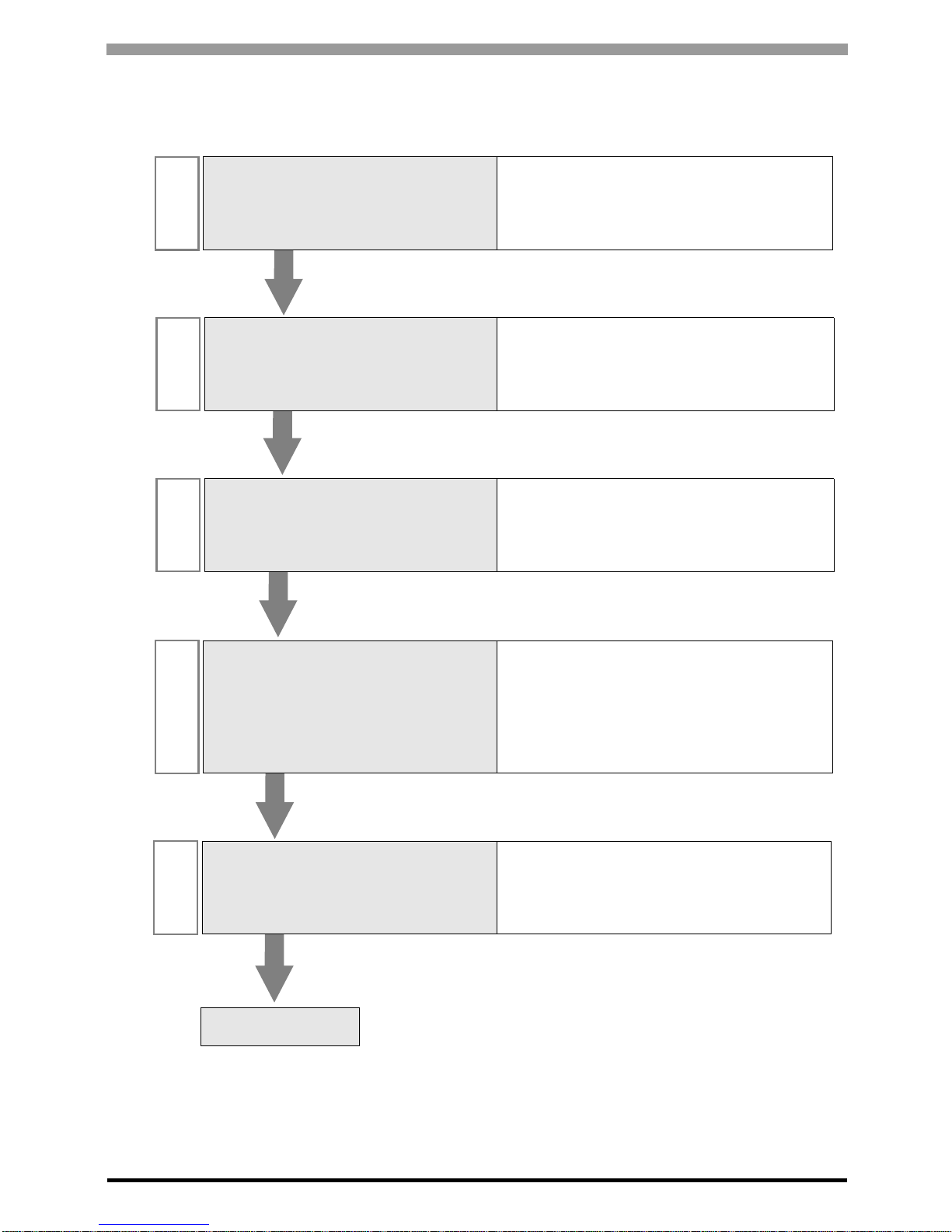
Introduction
This manual describes how to connect the Display and the External Device (target PLC).
In this manual, the connection procedure is described in the sections identified below:
1
System Configuration
This section lists the types of External
Devices and SIO that you can connect.
)"1 System Configuration" (page 3)
2
External Devices Selection
Select a model (series) of the External
Device and its connection method.
)"2 External Devices Selection" (page 9)
3
Communication Settings
This section shows setting examples for
communicating between the Display and
the External Device.
)"3 Communication Settings" (page 10)
4
Setup Items
This section describes communication
setup items on the Display.
Set the Display’s communication settings
in GP Pro-EX or in offline mode.
)"4 Setup Items" (page 58)
5
Cable Diagrams
This section shows cables and adapters
for connecting the Display and the
External Device.
)"5 Cable Diagrams" (page 62)
Operation
FREQROL Inverter Driver
GP-Pro EX Device/PLC Connection Manual
3
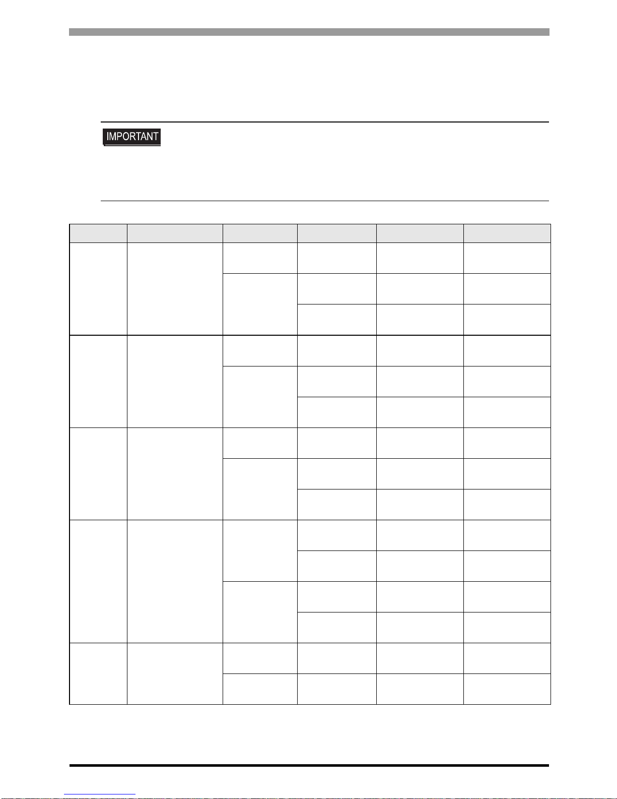
1 System Configuration
The following table lists system configurations for connecting Mitsubishi Electric Corporation External Devices
and the Display.
• If problems such as communication interruptions due to a disconnection of the signal
wire or malfunction of the Display cannot be detected on the inverter side, implement
a precautionary measure by using the inverter’s communication retry function or
communication check functi on . Refer to your External Device manual for details.
• Do not reset the inverter while communication is enabled. This may cause
malfunction. Prior to resetting the inverter, take the Display offline.
Series Inverter
*1
Link I/F SIO Type Setting Example Cable Diagram
FR-A700
FR-A720-K
FR-A740-K
PU connector on
the Inverter
RS-422/485
(4 wire )
"Setting Example 1"
(page 10)
" Cable Diagram 1"
(page 62)
RS-485 terminal
on the Inverter
RS-422/485
(4 wire )
"Setting Example 2"
(page 12)
" Cable Diagram 2"
(page 66)
RS-422/485
(2 wire)
"Setting Example 3"
(page 14)
" Cable Diagram 3"
(page 73)
FR-A701 FR-A721-K
PU connector on
the Inverter
RS-422/485
(4 wire )
"Setting Example 1"
(page 10)
" Cable Diagram 1"
(page 62)
RS-485 terminal
on the Inverter
RS-422/485
(4 wire )
"Setting Example 2"
(page 12)
" Cable Diagram 2"
(page 66)
RS-422/485
(2 wire)
"Setting Example 3"
(page 14)
" Cable Diagram 3"
(page 73)
FR-F700
FR-F720-K
FR-F740-K
PU connector on
the Inverter
RS-422/485
(4 wire )
"Setting Example 4"
(page 16)
" Cable Diagram 1"
(page 62)
RS-485 terminal
on the Inverter
RS-422/485
(4 wire )
"Setting Example 5"
(page 18)
" Cable Diagram 2"
(page 66)
RS-422/485
(2 wire)
"Setting Example 6"
(page 20)
" Cable Diagram 3"
(page 73)
FR-E700
FR-E720-K
FR-E740-K
FR-E720S-K
FR-E710W-K
PU connector on
the Inverter
RS-422/485
(4 wire )
"Setting Example 7"
(page 22)
" Cable Diagram 4"
(page 84)
*2
RS-422/485
(2 wire)
"Setting Example 8"
(page 24)
" Cable Diagram 5"
(page 97)
RS-485 terminal
on FR-E7TR
RS-422/485
(4 wire )
"Setting Example 7"
(page 22)
" Cable Diagram 8"
(page 137)
RS-422/485
(2 wire)
"Setting Example 8"
(page 24)
" Cable Diagram 9"
(page 144)
FR-V500
FR-V520-K
FR-V540-K
PU connector on
the Inverter
RS-422/485
(4 wire )
"Setting Example 9"
(page 26)
" Cable Diagram 4"
(page 84)
*2
T erminal on
FR-A5NR
RS-422/485
(4 wire )
"Setting Example
10" (page 28)
" Cable Diagram 7"
(page 130)

FREQROL Inverter Driver
GP-Pro EX Device/PLC Connection Manual
4
FR-V500L
FR-V520L-K
FR-V540L-K
PU connector on
the Inverter
RS-422/485
(4 wire )
"Setting Example 9"
(page 26)
" Cable Diagram 4"
(page 84)
*2
T erminal on
FR-A5NR
RS-422/485
(4 wire )
"Setting Example
10" (page 28)
" Cable Diagram 7"
(page 130)
FR-A500
FR-A520-K
FR-A540-K
PU connector on
the Inverter
RS-422/485
(4 wire )
"Setting Example
11" (page 30)
" Cable Diagram 4"
(page 84)
*2
T erminal on
FR-A5NR
RS-422/485
(4 wire )
"Setting Example
12" (page 32)
" Cable Diagram 7"
(page 130)
FR-A500L
FR-A520L-K
FR-A540L-K
PU connector on
the Inverter
RS-422/485
(4 wire )
"Setting Example
11" (page 30)
" Cable Diagram 4"
(page 84)
*2
T erminal on
FR-A5NR
RS-422/485
(4 wire )
"Setting Example
12" (page 32)
" Cable Diagram 7"
(page 130)
FR-F500
FR-F520-K
FR-F540-K
PU connector on
the Inverter
RS-422/485
(4 wire )
"Setting Example
13" (page 34)
" Cable Diagram 4"
(page 84)
*2
T erminal on
FR-A5NR
RS-422/485
(4 wire )
"Setting Example
14" (page 36)
" Cable Diagram 7"
(page 130)
FR-F500L
FR-F520L-K
FR-F540L-K
PU connector on
the Inverter
RS-422/485
(4 wire )
"Setting Example
13" (page 34)
" Cable Diagram 4"
(page 84)
*2
T erminal on
FR-A5NR
RS-422/485
(4 wire )
"Setting Example
14" (page 36)
" Cable Diagram 7"
(page 130)
FR-E500
FR-E520-K
FR-E540-K
FR-E520S-K
FR-E510W-K
PU connector on
the Inverter
RS-422/485
(4 wire )
"Setting Example
15" (page 38)
" Cable Diagram 4"
(page 84)
*2
FR-C500 FR-C520-K
PU connector on
the Inverter
RS-422/485
(4 wire )
"Setting Example
16" (page 40)
" Cable Diagram 4"
(page 84)
*2
FR-S500
FR-S520-K(-R)(-C)
FR-S540-K(-R)
FR-S520S-K(-R)
FR-S510W-K(-R)
FR-S520E-K(-C)
FR-S540E-K
FR-S520SE-K
FR-S510WE-K
RS-485
connector on the
Inverter
RS-422/485
(4 wire )
"Setting Example
17" (page 42)
" Cable Diagram 4"
(page 84)
*2
FR-S520E-K-NMR
RS-485 terminal
on the Inverter
RS-422/485
(2 wire)
"Setting Example
18" (page 44)
" Cable Diagram 6"
(page 119)
FR-F500J
FR-F520J-K(F)
FR-F540J-K(F)
RS-485
connector on the
Inverter
RS-422/485
(4 wire )
"Setting Example
19" (page 46)
" Cable Diagram 4"
(page 84)
*2
FRB,B3(A500)
FR-B-K
FR-B3-(N)(H)K
PU connector on
the Inverter
RS-422/485
(4 wire )
"Setting Example
20" (page 48)
" Cable Diagram 4"
(page 84)
*2
T erminal on
FR-A5NR
RS-422/485
(4 wire )
"Setting Example
21" (page 50)
" Cable Diagram 7"
(page 130)
Series Inverter
*1
Link I/F SIO Type Setting Example Cable Diagram

FREQROL Inverter Driver
GP-Pro EX Device/PLC Connection Manual
5
FRB,B3(A700)
FR-B-K
FR-B3-(N)(H)K
PU connector on
the Inverter
RS-422/485
(4 wire )
"Setting Example
22" (page 52)
" Cable Diagram 1"
(page 62)
RS-485 terminal
on the Inverter
RS-422/485
(4 wire )
"Setting Example
23" (page 54)
" Cable Diagram 2"
(page 66)
RS-422/485
(2 wire)
"Setting Example
24" (page 56)
" Cable Diagram 3"
(page 73)
*1 varies depending on each inverter’s capacity.
*2 Cable Diagram 1 can be used for 1:1 Connection.
Series Inverter
*1
Link I/F SIO Type Setting Example Cable Diagram
FREQROL Inverter Driver
GP-Pro EX Device/PLC Connection Manual
6
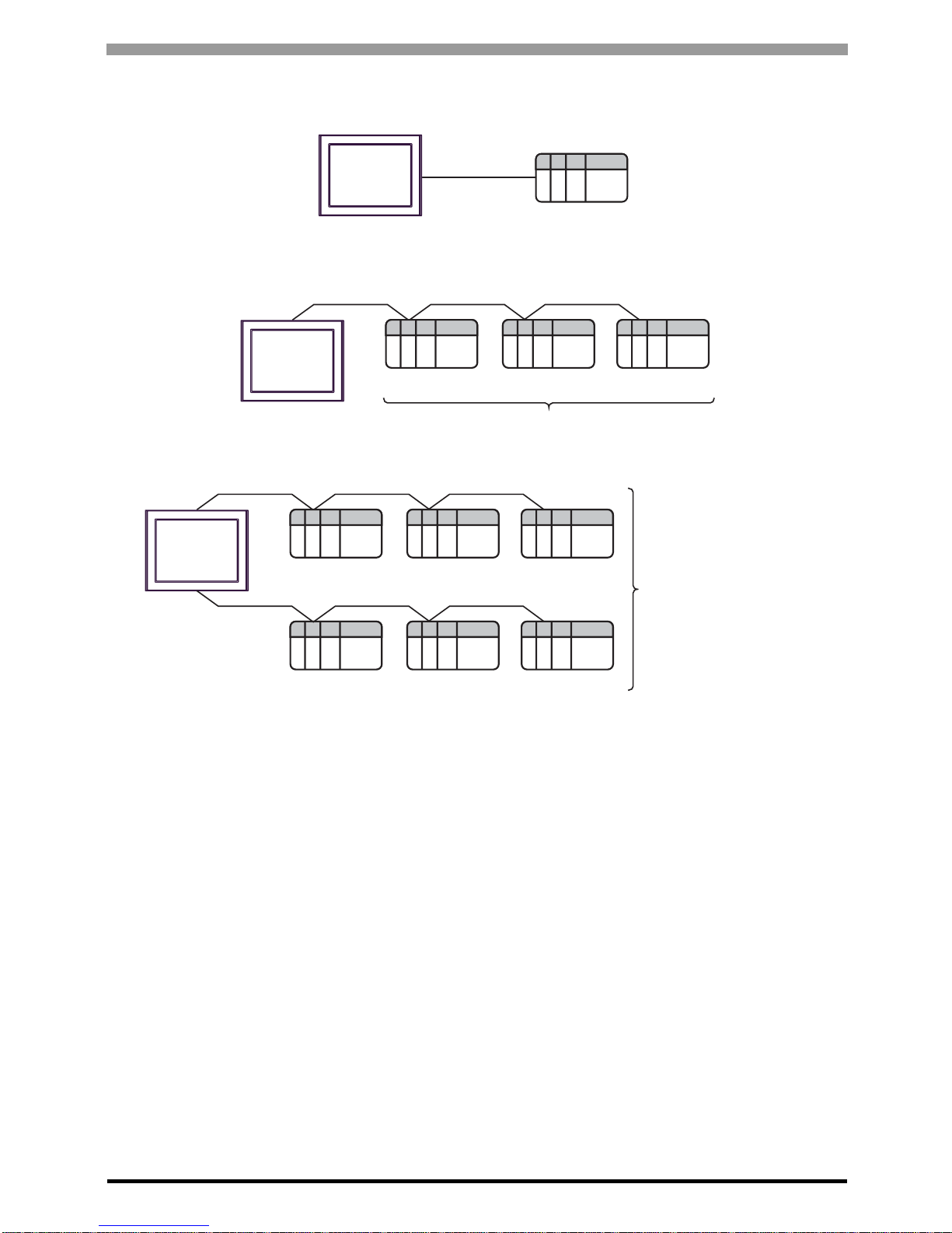
Connection Configuration
• 1:1 Connection
• 1:n Connection
Display
External Device
Display
External Device External Device External Device
Maximum number of External Devices: 16
Display
External Device External Device External Device
External Device External Device External Device
Maximum number of
External Devices: 32
FREQROL Inverter Driver
GP-Pro EX Device/PLC Connection Manual
7
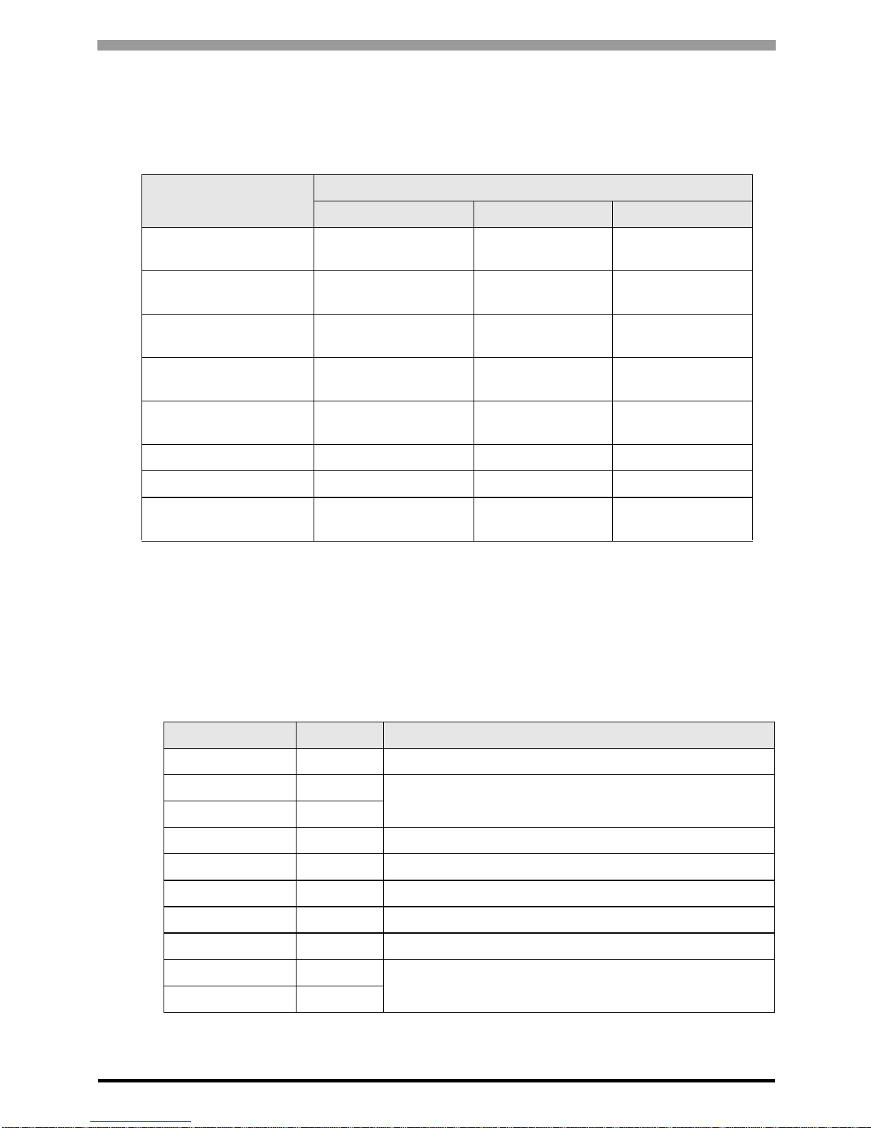
IPC COM Port
When connecting IPC with an External Device, the COM port used depends on the series and SIO type. Please
refer to the IPC manual for details.
Usable port
DIP Switch setting: RS-232C
Series
Usable Port
RS-232C RS-422/485(4 wire) RS-422/485(2 wire)
PS-2000B
COM1
*1
, COM2,
COM3
*1
, COM4
*1 The RI/5V can be switched. Use the IPC’s switch to change if necessary.
--
PS-3450A, PS-3451A,
PS3000-BA, PS3001-BD
COM1, COM2
*1*2
COM2
*1*2
COM2
*1*2
PS-3650A (T41 model),
PS-3651A (T41 model)
COM1
*1
--
PS-3650A (T42 model),
PS-3651A (T42 model)
COM1
*1*2
, COM2 COM1
*1*2
COM1
*1*2
PS-3700A (Pentium®4-M)
PS-3710A
COM1*1, COM2*1,
COM3*2, COM4
*2 Set up the SIO type with the DIP Switch. Please set up as follows according to SIO type to be used.
COM3
*2
COM3
*2
PS-3711A COM1*1, COM2
*2
COM2
*2
COM2
*2
PS4000
*3
*3 When making communication between an External Device and COM port on the Expansion slot,
only RS-232C is supported. However, ER (DTR/CTS) control cannot be executed because of the
specification of COM port.
For connection with External Device, use user-created cables and disable Pin Nos. 1, 4, 6 and 9.
Please refer to the IPC manual for details of pin layout.
COM1, COM2 - -
PL3000
COM1
*1*2
, COM2*1,
COM3, COM4
COM1
*1*2
COM1
*1*2
DIP Switch Setting Description
1OFF
*1
*1 When using PS-3450A, PS-3451A, PS3000-BA and PS3001-BD, turn ON the set value.
Reserved (always OFF)
2OFF
SIO type: RS-232C
3OFF
4 OFF Output mode of SD (TXD) data: Always output
5 OFF Terminal resistance (220Ω) insertion to SD (TXD): None
6 OFF Terminal resistance (220Ω) insertion to RD (RXD): None
7 OFF Short-circuit of SDA (TXA) and RDA (RXA): Not available
8 OFF Short-circuit of SDB (TXB) and RDB (RXB): Not available
9OFF
RS (RTS) Auto control mode: Disabled
10 OFF
FREQROL Inverter Driver
GP-Pro EX Device/PLC Connection Manual
8
DIP Switch setting: RS-422/485 (4 wire)
DIP Switch setting: RS-422/485 (2 wire)
DIP Switch Setting Description
1 OFF Reserved (always OFF)
2ON
SIO type: RS-422/485
3ON
4 OFF Output mode of SD (TXD) data: Always output
5 OFF Terminal resistance (220Ω) insertion to SD (TXD): None
6 OFF Terminal resistance (220Ω) insertion to RD (RXD): None
7 OFF Short-circuit of SDA (TXA) and RDA (RXA): Not available
8 OFF Short-circuit of SDB (TXB) and RDB (RXB): Not available
9OFF
RS (RTS) Auto control mode: Disabled
10 OFF
DIP Switch Setting Description
1 OFF Reserved (always OFF)
2ON
SIO type: RS-422/485
3ON
4 OFF Output mode of SD (TXD) data: Always output
5 OFF Terminal resistance (220Ω) insertion to SD (TXD): None
6 OFF Terminal resistance (220Ω) insertion to RD (RXD): None
7 ON Short-circuit of SDA (TXA) and RDA (RXA): Available
8 ON Short-circuit of SDB (TXB) and RDB (RXB): Available
9ON
RS (RTS) Auto control mode: Enabled
10 ON
FREQROL Inverter Driver
GP-Pro EX Device/PLC Connection Manual
9
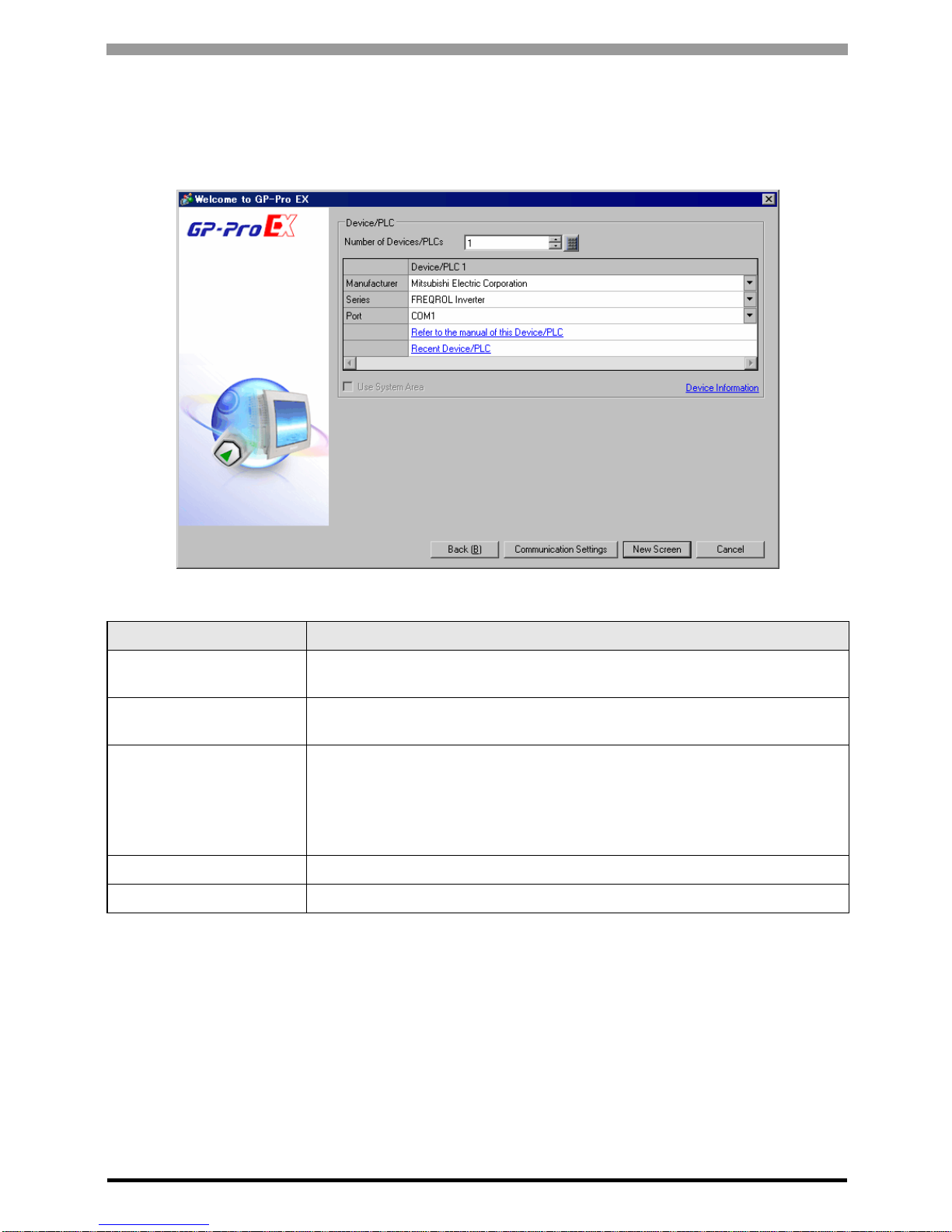
2 External Devices Selection
Select the External Device to be connected to the Display .
Setup Items Setup Description
Number of Devices/PLCs
Enter an integer from 1 to 4 to define the number of Devices/PLCs to connect to the
display.
Manufacturer
Select the manufacturer of the External Device to connect. Select "Mitsubishi Electric
Corporation".
Series
Select the External Device model (series) and the connection method. Select
"FREQROL Inverter".
In System configuration, make sure the External Device you are connecting is
supported by "FREQROL Inverter".
)"1 System Configuration" (page 3)
Port Select the Display port to be connected to the External Device.
Use System Area Not available in this driver .
FREQROL Inverter Driver
GP-Pro EX Device/PLC Connection Manual
10
3 Communication Settings
This section provides examples of communication settings recommended by Pro-face for the Display and the
External Device.
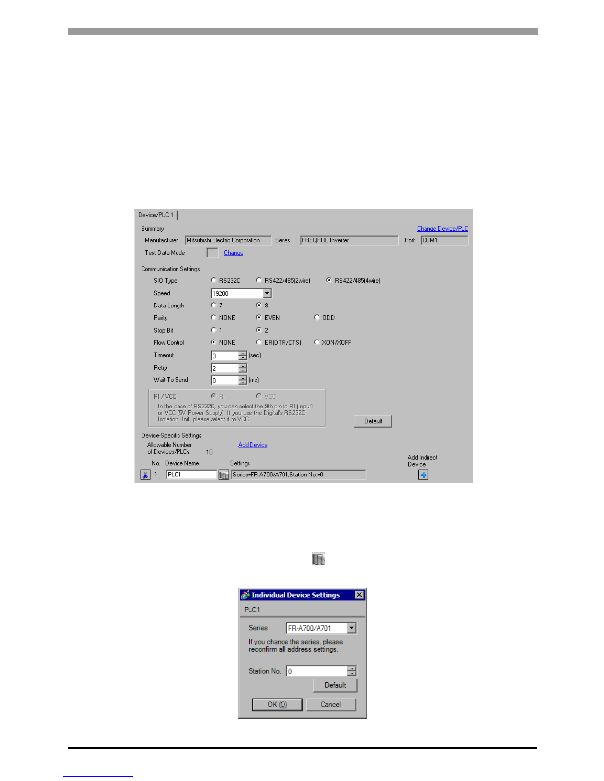
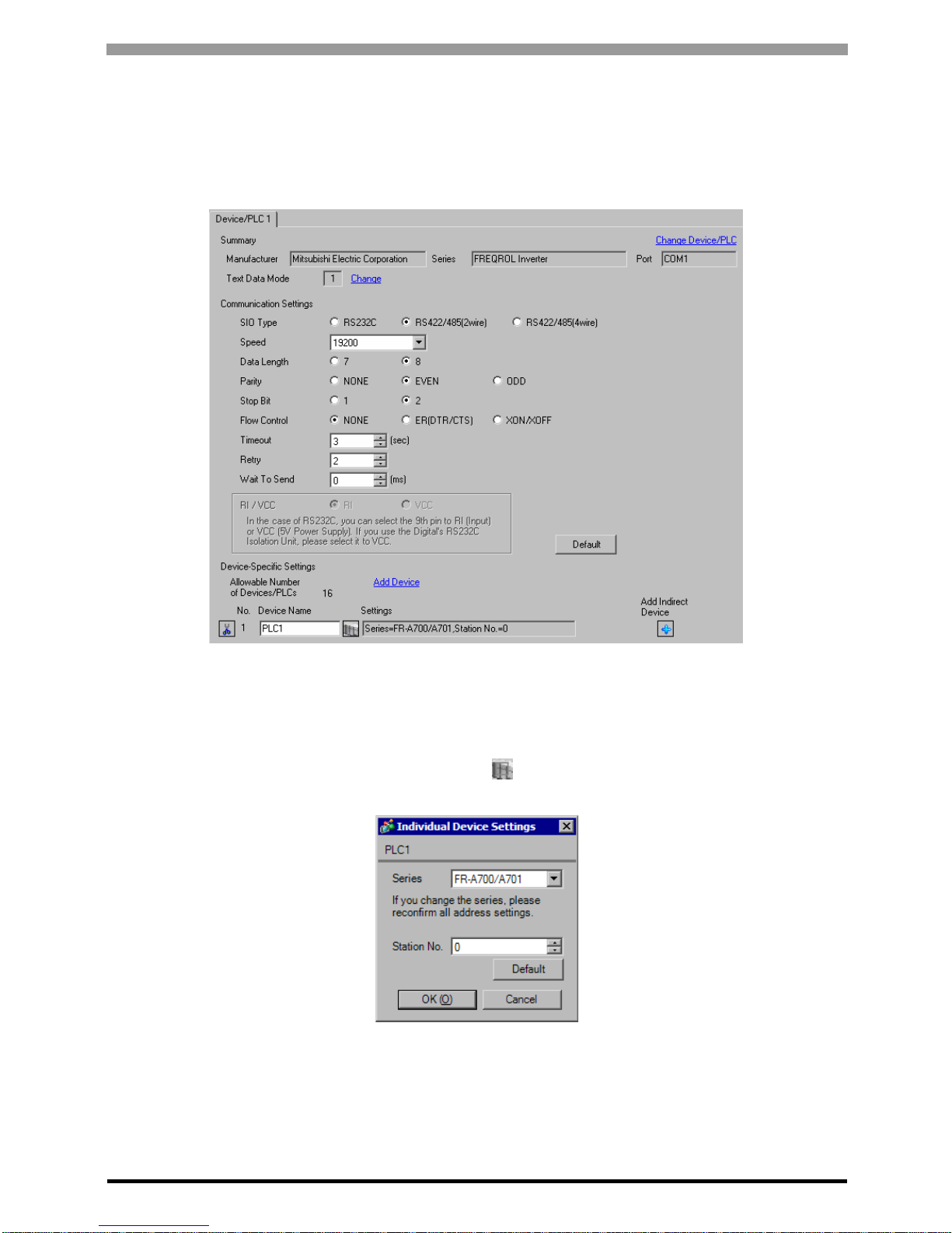
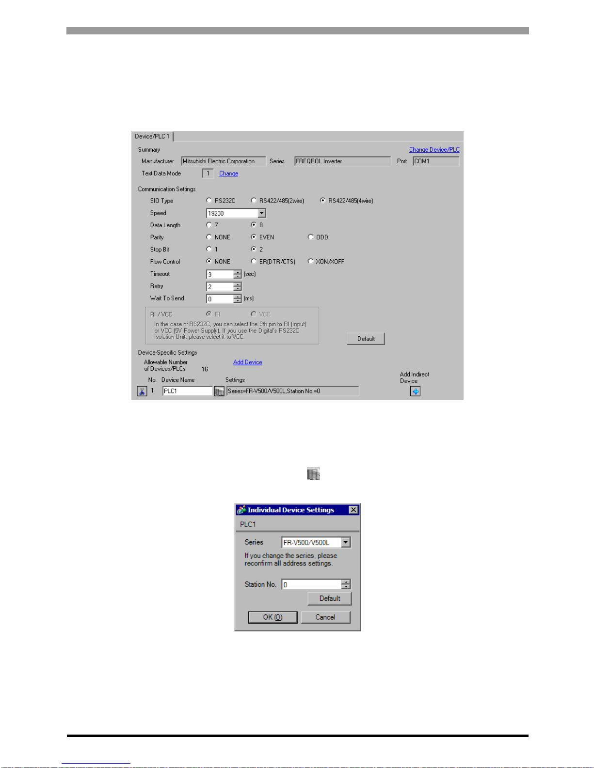
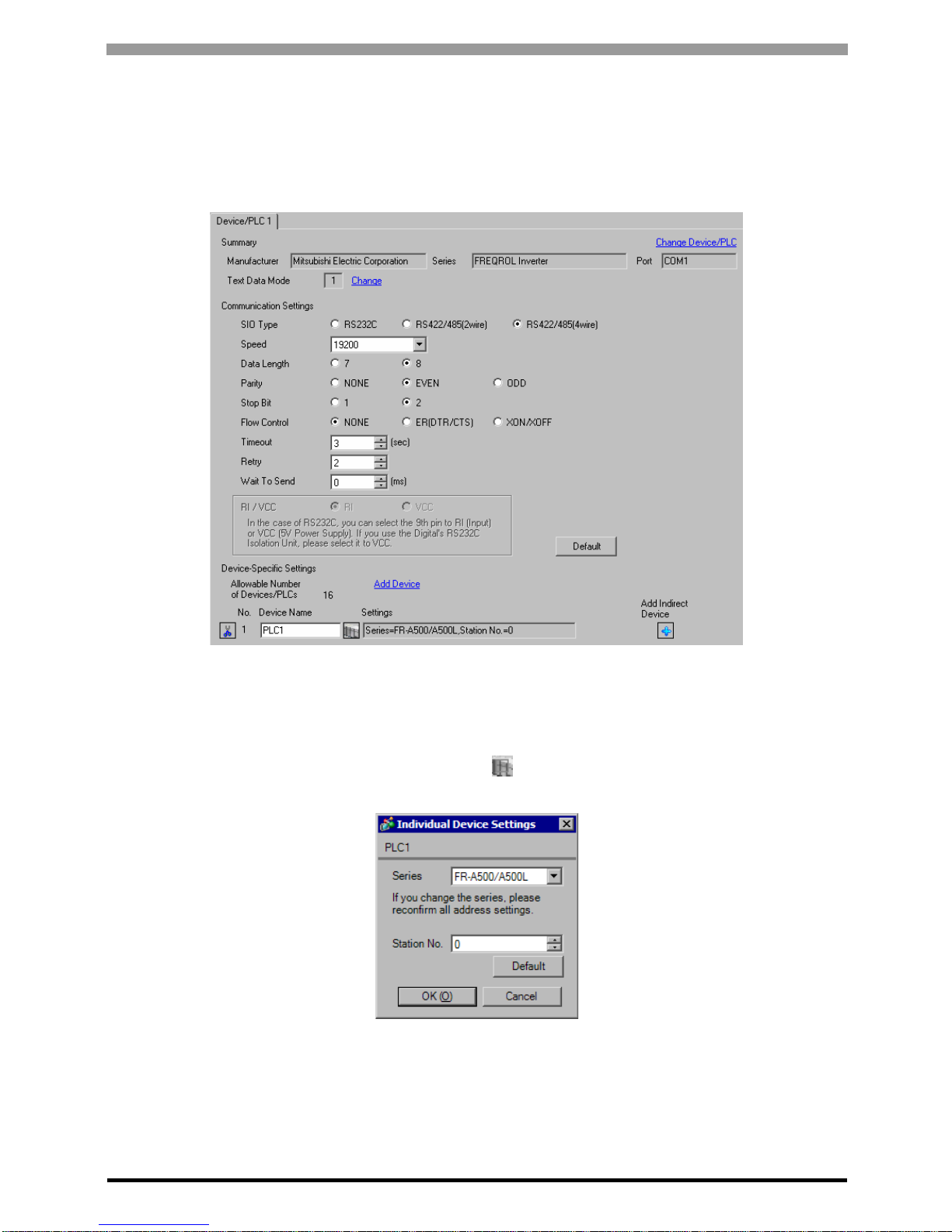
3.1 Setting Example 1
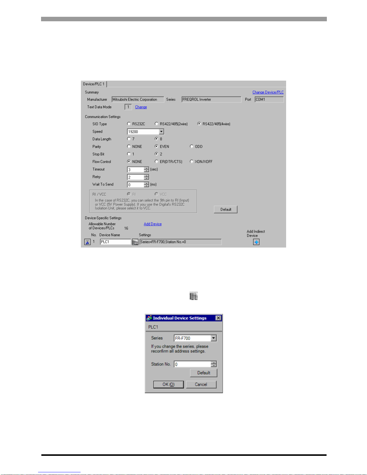
GP Pro-EX Settings
Communication Settings
T o display the setup screen, from the [Project] menu, point to [System Settings] and select [Device/PLC].
Device Setting
To display the [Individual Device Settings] dialog box, from [Device-Specific Settings] in the [Device/PLC]
window, select the external device and click [Settings] . To connect multiple External Devices, from [DeviceSpecific Settings] in the [Device/PLC] window , click [Add Device] to add another External Device.

FREQROL Inverter Driver
GP-Pro EX Device/PLC Connection Manual
11
External Device Settings
Use the PU/EXT key, MODE key, M dial and SET key in the operation panel of the CPU unit for External Device
communication settings.
Refer to your External Device manual for details.
1 Turn ON the power supply.
2 Press PU/EXT key to select the PU operation mode.
3 Press MODE key to select the parameter setting mode.
4 Display the setting parameter number with M dial.
5 Press SET key to display the current setting value.
6 Set the setting value with M dial.
7 Press SET key to confirm the setting value.
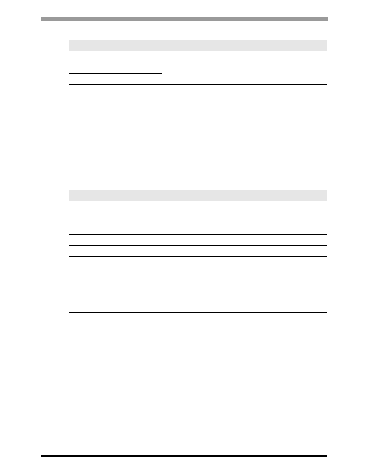
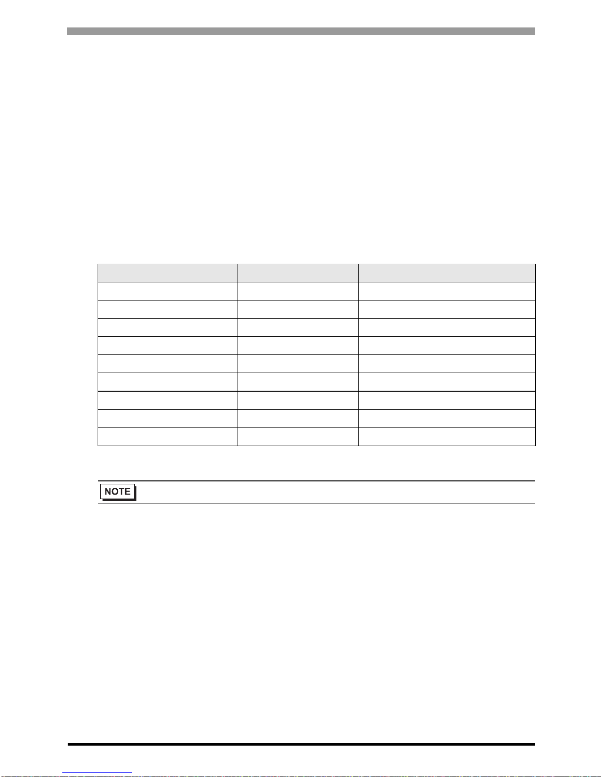
Setting Parameter Number Setting Value Setup Description
117 0 PU communication station number
118 192 PU communication speed
119 1 PU communication stop bit length
120 2 PU communication parity check
121 1 Number of PU communication retries
122 Any Except 0 PU communication check time interval
123 9999 PU communication waiting time setting
124 1
PU communication CR/LF presence/
absence selection
• Always restart the Eternal Device after changing parameters.
FREQROL Inverter Driver
GP-Pro EX Device/PLC Connection Manual
12
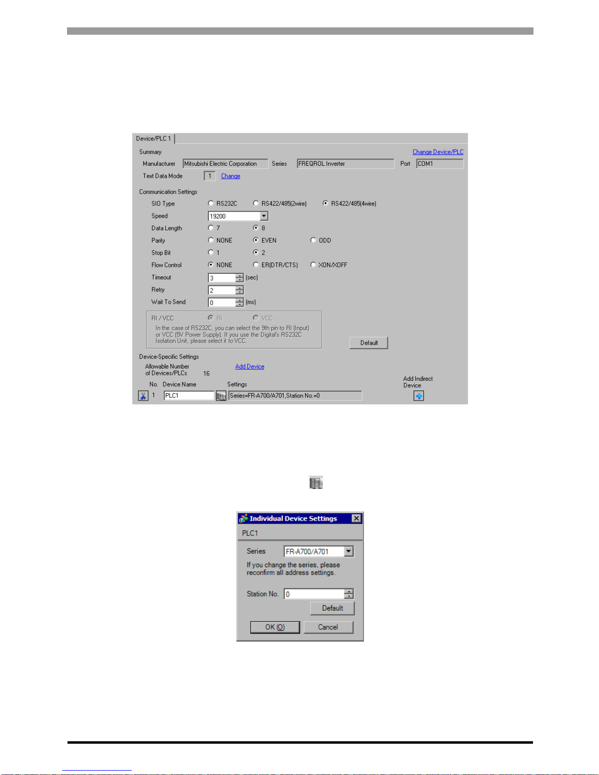
3.2 Setting Example 2
GP Pro-EX Settings
Communication Settings
T o display the setup screen, from the [Project] menu, point to [System Settings] and select [Device/PLC].
Device Setting
To display the [Individual Device Settings] dialog box, from [Device-Specific Settings] in the [Device/PLC]
window, select the external device and click [Settings] . To connect multiple External Devices, from [DeviceSpecific Settings] in the [Device/PLC] window , click [Add Device] to add another External Device.
FREQROL Inverter Driver
GP-Pro EX Device/PLC Connection Manual
13
External Device Settings
Use the PU/EXT key, MODE key, M dial and SET key in the operation panel of the CPU unit for External Device
communication settings.
Refer to your External Device manual for details.
1 Turn ON the power supply.
2 Press PU/EXT key to select the PU operation mode.
3 Press MODE key to select the parameter setting mode.
4 Display the setting parameter number with M dial.
5 Press SET key to display the current setting value.
6 Set the setting value with M dial.
7 Press SET key to confirm the setting value.
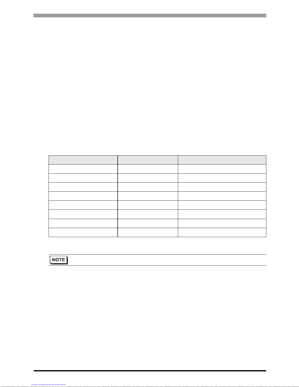
Setting Parameter Number Setting Value Setup Description
331 0 RS-485 communication station
332 192 RS-485 communication speed
333 1 RS-485 communication stop bit length
334 2
RS-485 communication parity check
selection
335 1 RS-485 communication retry count
336 Any Except 0 RS-485 communication check time interval
337 9999
RS-485 communication waiting time
setting
341 1 RS-485 communication CR/LF selection
549 0 Protocol selection
• Always restart the Eternal Device after changing parameters.
FREQROL Inverter Driver
GP-Pro EX Device/PLC Connection Manual
14
3.3 Setting Example 3
GP Pro-EX Settings
Communication Settings
T o display the setup screen, from the [Project] menu, point to [System Settings] and select [Device/PLC].
Device Setting
To display the [Individual Device Settings] dialog box, from [Device-Specific Settings] in the [Device/PLC]
window, select the external device and click [Settings] . To connect multiple External Devices, from [DeviceSpecific Settings] in the [Device/PLC] window , click [Add Device] to add another External Device.
FREQROL Inverter Driver
GP-Pro EX Device/PLC Connection Manual
15
External Device Settings
Use the PU/EXT key, MODE key, M dial and SET key in the operation panel of the CPU unit for External Device
communication settings.
Refer to your External Device manual for details.
1 Turn ON the power supply.
2 Press PU/EXT key to select the PU operation mode.
3 Press MODE key to select the parameter setting mode.
4 Display the setting parameter number with M dial.
5 Press SET key to display the current setting value.
6 Set the setting value with M dial.
7 Press SET key to confirm the setting value.
Setting Parameter Number Setting Value Setup Description
331 0 RS-485 communication station
332 192 RS-485 communication speed
333 1 RS-485 communication stop bit length
334 2
RS-485 communication parity check
selection
335 1 RS-485 communication retry count
336 Any Except 0 RS-485 communication check time interval
337 9999 RS-485 communication waiting time setting
341 1 RS-485 communication CR/LF selection
549 0 Protocol selection
• Always restart the Eternal Device after changing parameters.
FREQROL Inverter Driver
GP-Pro EX Device/PLC Connection Manual
16
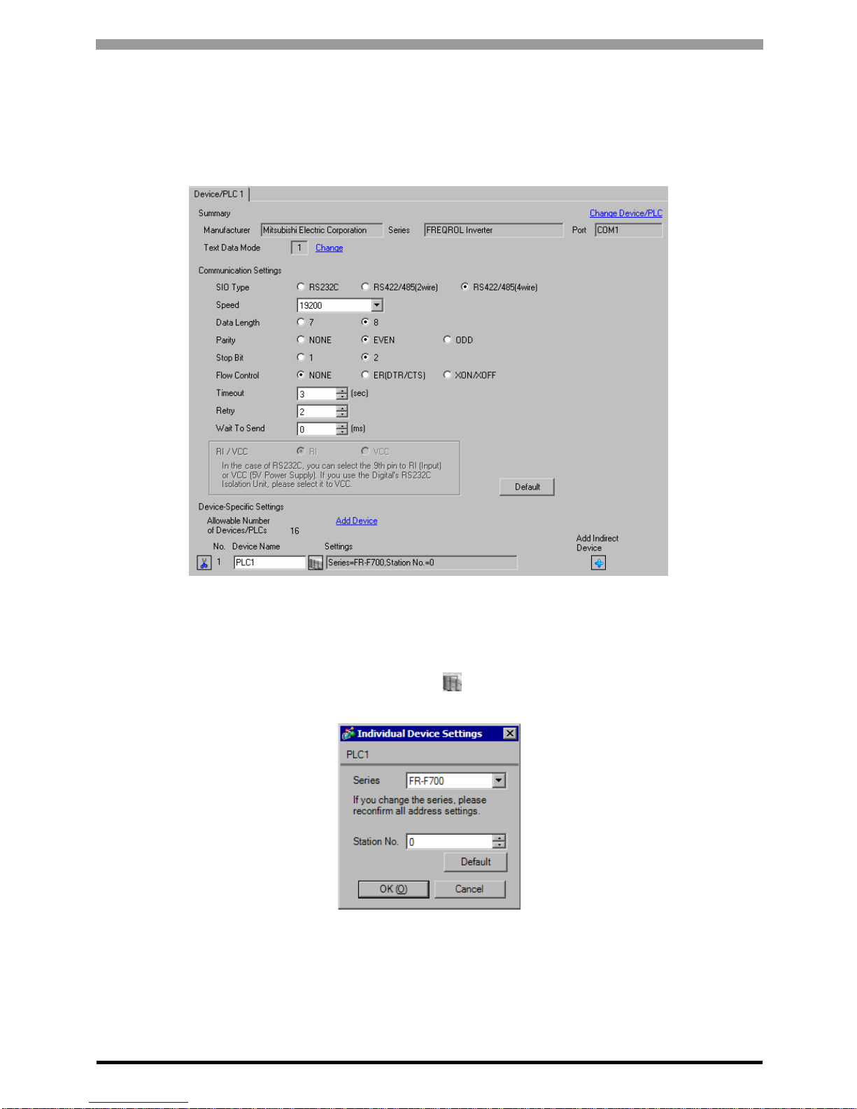
3.4 Setting Example 4
GP Pro-EX Settings
Communication Settings
T o display the setup screen, from the [Project] menu, point to [System Settings] and select [Device/PLC].
Device Setting
To display the [Individual Device Settings] dialog box, from [Device-Specific Settings] in the [Device/PLC]
window, select the external device and click [Settings] . To connect multiple External Devices, from [DeviceSpecific Settings] in the [Device/PLC] window , click [Add Device] to add another External Device.
FREQROL Inverter Driver
GP-Pro EX Device/PLC Connection Manual
17
External Device Settings
Use the PU/EXT key, MODE key, M dial and SET key in the operation panel of the CPU unit for External Device
communication settings.
Refer to your External Device manual for details.
1 Turn ON the power supply.
2 Press PU/EXT key to select the PU operation mode.
3 Press MODE key to select the parameter setting mode.
4 Display the setting parameter number with M dial.
5 Press SET key to display the current setting value.
6 Set the setting value with M dial.
7 Press SET key to confirm the setting value.
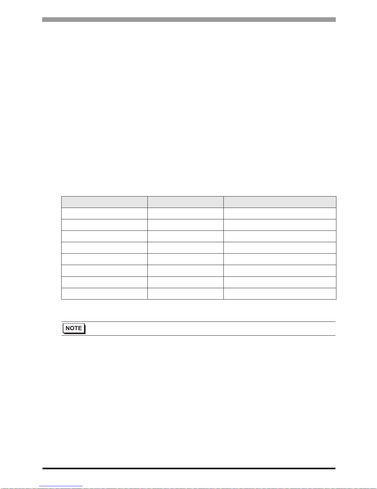
Setting Parameter Number Setting Value Setup Description
117 0 PU communication station number
118 192 PU communication speed
119 1 PU communication stop bit length
120 2 PU communication parity check
121 1 Number of PU communication retries
122 Any Except 0 PU communication check time interval
123 9999 PU communication waiting time setting
124 1
PU communication CR/LF presence/
absence selection
• Always restart the Eternal Device after changing parameters.
FREQROL Inverter Driver
GP-Pro EX Device/PLC Connection Manual
18
3.5 Setting Example 5
GP Pro-EX Settings
Communication Settings
T o display the setup screen, from the [Project] menu, point to [System Settings] and select [Device/PLC].
Device Setting
To display the [Individual Device Settings] dialog box, from [Device-Specific Settings] in the [Device/PLC]
window, select the external device and click [Settings] . To connect multiple External Devices, from [DeviceSpecific Settings] in the [Device/PLC] window , click [Add Device] to add another External Device.

FREQROL Inverter Driver
GP-Pro EX Device/PLC Connection Manual
19
External Device Settings
Use the PU/EXT key, MODE key, M dial and SET key in the operation panel of the CPU unit for External Device
communication settings.
Refer to your External Device manual for details.
1 Turn ON the power supply.
2 Press PU/EXT key to select the PU operation mode.
3 Press MODE key to select the parameter setting mode.
4 Display the setting parameter number with M dial.
5 Press SET key to display the current setting value.
6 Set the setting value with M dial.
7 Press SET key to confirm the setting value.
Setting Parameter Number Setting Value Setup Description
331 0 RS-485 communication station
332 192 RS-485 communication speed
333 1 RS-485 communication stop bit length
334 2
RS-485 communication parity check
selection
335 1 RS-485 communication retry count
336 Any Except 0 RS-485 communication check time interval
337 9999 RS-485 communication waiting time setting
341 1 RS-485 communication CR/LF selection
549 0 Protocol selection
• Always restart the Eternal Device after changing parameters.

FREQROL Inverter Driver
GP-Pro EX Device/PLC Connection Manual
20
3.6 Setting Example 6
GP Pro-EX Settings
Communication Settings
T o display the setup screen, from the [Project] menu, point to [System Settings] and select [Device/PLC].
Device Setting
To display the [Individual Device Settings] dialog box, from [Device-Specific Settings] in the [Device/PLC]
window, select the external device and click [Settings] . To connect multiple External Devices, from [DeviceSpecific Settings] in the [Device/PLC] window , click [Add Device] to add another External Device.

FREQROL Inverter Driver
GP-Pro EX Device/PLC Connection Manual
21
External Device Settings
Use the PU/EXT key, MODE key, M dial and SET key in the operation panel of the CPU unit for External Device
communication settings.
Refer to your External Device manual for details.
1 Turn ON the power supply.
2 Press PU/EXT key to select the PU operation mode.
3 Press MODE key to select the parameter setting mode.
4 Display the setting parameter number with M dial.
5 Press SET key to display the current setting value.
6 Set the setting value with M dial.
7 Press SET key to confirm the setting value.
Setting Parameter Number Setting Value Setup Description
331 0 RS-485 communication station
332 192 RS-485 communication speed
333 1 RS-485 communication stop bit length
334 2
RS-485 communication parity check
selection
335 1 RS-485 communication retry count
336 Any Except 0 RS-485 communication check time interval
337 9999
RS-485 communication waiting time
setting
341 1 RS-485 communication CR/LF selection
549 0 Protocol selection
• Always restart the Eternal Device after changing parameters.
FREQROL Inverter Driver
GP-Pro EX Device/PLC Connection Manual
22
3.7 Setting Example 7
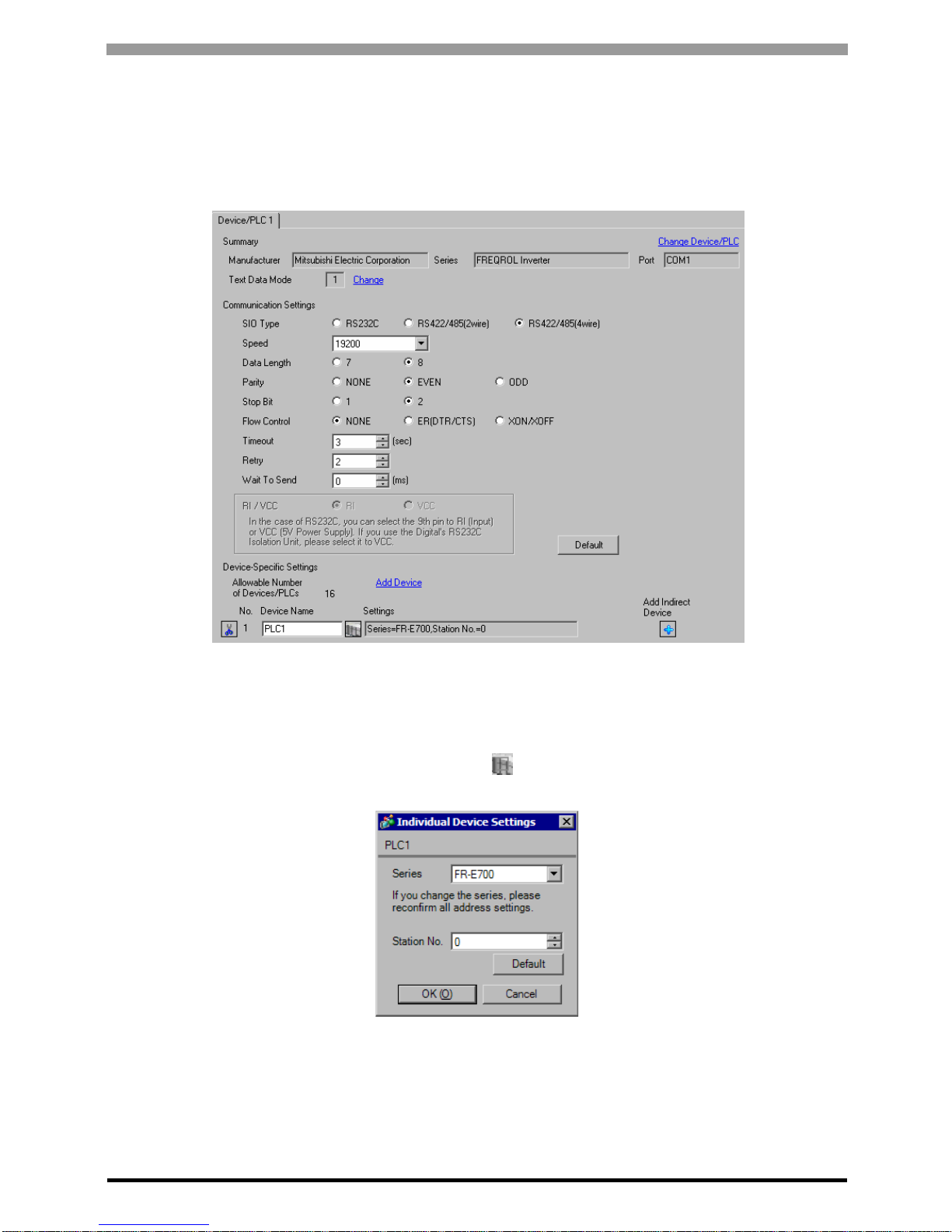
GP Pro-EX Settings
Communication Settings
T o display the setup screen, from the [Project] menu, point to [System Settings] and select [Device/PLC].
Device Setting
To display the [Individual Device Settings] dialog box, from [Device-Specific Settings] in the [Device/PLC]
window, select the external device and click [Settings] . To connect multiple External Devices, from [DeviceSpecific Settings] in the [Device/PLC] window , click [Add Device] to add another External Device.
FREQROL Inverter Driver
GP-Pro EX Device/PLC Connection Manual
23
External Device Settings
Use the PU/EXT key, MODE key, M dial and SET key in the operation panel of the CPU unit for External Device
communication settings.
Refer to your External Device manual for details.
1 Turn ON the power supply.
2 Press PU/EXT key to select the PU operation mode.
3 Press MODE key to select the parameter setting mode.
4 Display the setting parameter number with M dial.
5 Press SET key to display the current setting value.
6 Set the setting value with M dial.
7 Press SET key to confirm the setting value.
Setting Parameter Number Setting Value Setup Description
117 0 PU communication station number
118 192 PU communication speed
119 1 PU communication stop bit length
120 2 PU communication parity check
121 1 Number of PU communication retries
122 Any Except 0 PU communication check time interval
123 9999 PU communication waiting time setting
124 1 PU communication CR/LF selection
549 0 Protocol selection
• Always restart the Eternal Device after changing parameters.

FREQROL Inverter Driver
GP-Pro EX Device/PLC Connection Manual
24
3.8 Setting Example 8
GP Pro-EX Settings
Communication Settings
T o display the setup screen, from the [Project] menu, point to [System Settings] and select [Device/PLC].
Device Setting
To display the [Individual Device Settings] dialog box, from [Device-Specific Settings] in the [Device/PLC]
window, select the external device and click [Settings] . To connect multiple External Devices, from [DeviceSpecific Settings] in the [Device/PLC] window , click [Add Device] to add another External Device.
FREQROL Inverter Driver
GP-Pro EX Device/PLC Connection Manual
25
External Device Settings
Use the PU/EXT key, MODE key, M dial and SET key in the operation panel of the CPU unit for External Device
communication settings.
Refer to your External Device manual for details.
1 Turn ON the power supply.
2 Press PU/EXT key to select the PU operation mode.
3 Press MODE key to select the parameter setting mode.
4 Display the setting parameter number with M dial.
5 Press SET key to display the current setting value.
6 Set the setting value with M dial.
7 Press SET key to confirm the setting value.
Setting Parameter Number Setting Value Setup Description
117 0 PU communication station number
118 192 PU communication speed
119 1 PU communication stop bit length
120 2 PU communication parity check
121 1 Number of PU communication retries
122 Any Except 0 PU communication check time interval
123 9999 PU communication waiting time setting
124 1 PU communication CR/LF selection
549 0 Protocol selection
• Always restart the Eternal Device after changing parameters.

FREQROL Inverter Driver
GP-Pro EX Device/PLC Connection Manual
26
3.9 Setting Example 9
GP Pro-EX Settings
Communication Settings
T o display the setup screen, from the [Project] menu, point to [System Settings] and select [Device/PLC].
Device Setting
To display the [Individual Device Settings] dialog box, from [Device-Specific Settings] in the [Device/PLC]
window, select the external device and click [Settings] . To connect multiple External Devices, from [DeviceSpecific Settings] in the [Device/PLC] window , click [Add Device] to add another External Device.
FREQROL Inverter Driver
GP-Pro EX Device/PLC Connection Manual
27
External Device Settings
Use the MODE key, SET key, up key, and down key in the operation panel of the CPU unit for External Device
communication settings.
Refer to your External Device manual for details.
1 Press MODE key to select the parameter setting mode.
2 Press SET key.
3 Press up key or down key to display the most significant digit of the parameter number.
4 Press SET key.
5 Press up key or down key to display the middle digit of the parameter number.
6 Press SET key.
7 Press up key or down key to display the least significant digit of the parameter number.
8 Press SET key to display the current setting value.
9 Press up key or down key to set the setting value.
10 Press SET key for 1.5 seconds to write the setting value.
Setting Parameter Number Setting Value Setup Description
117 0 Communication station number
118 192 Communication speed
119 1 Stop bit length/data length
120 2 Parity check presence/absence
121 1 Number of communication retries
122 Any Except 0 Communication check time interval
123 9999 Waiting time setting
124 1 CR, LF presence/absence selection
• Always restart the Eternal Device after changing parameters.
FREQROL Inverter Driver
GP-Pro EX Device/PLC Connection Manual
28
3.10 Setting Example 10
GP Pro-EX Settings
Communication Settings
T o display the setup screen, from the [Project] menu, point to [System Settings] and select [Device/PLC].
Device Setting
To display the [Individual Device Settings] dialog box, from [Device-Specific Settings] in the [Device/PLC]
window, select the external device and click [Settings] . To connect multiple External Devices, from [DeviceSpecific Settings] in the [Device/PLC] window , click [Add Device] to add another External Device.
FREQROL Inverter Driver
GP-Pro EX Device/PLC Connection Manual
29
External Device Settings
Use the MODE key, SET key, up key, and down key in the operation panel of the CPU unit for External Device
communication settings.
Refer to your External Device manual for details.
1 Press MODE key to select the parameter setting mode.
2 Press SET key.
3 Press up key or down key to display the most significant digit of the parameter number.
4 Press SET key.
5 Press up key or down key to display the middle digit of the parameter number.
6 Press SET key.
7 Press up key or down key to display the least significant digit of the parameter number.
8 Press SET key to display the current setting value.
9 Press up key or down key to set the setting value.
10 Press SET key for 1.5 seconds to write the setting value.
Setting Parameter Number Setting Value Setup Description
331 0 Communication station number
332 192 Communication speed
333 1 Stop bit length
334 2 Parity check presence/absence
335 1 Number of communication retries
336 Any Except 0 Communication check time interval
337 9999 W ait ing time setting
341 1 CR/LF presence/absence selection
• Always restart the Eternal Device after changing parameters.
FREQROL Inverter Driver
GP-Pro EX Device/PLC Connection Manual
30
3.11 Setting Example 11
GP Pro-EX Settings
Communication Settings
T o display the setup screen, from the [Project] menu, point to [System Settings] and select [Device/PLC].
Device Setting
To display the [Individual Device Settings] dialog box, from [Device-Specific Settings] in the [Device/PLC]
window, select the external device and click [Settings] . To connect multiple External Devices, from [DeviceSpecific Settings] in the [Device/PLC] window , click [Add Device] to add another External Device.

FREQROL Inverter Driver
GP-Pro EX Device/PLC Connection Manual
31
External Device Settings
Use the MODE key, SET key, up key, and down key in the operation panel of the CPU unit for External Device
communication settings.
Refer to your External Device manual for details.
1 Press MODE key to select the parameter setting mode.
2 Press SET key.
3 Press up key or down key to display the most significant digit of the parameter number.
4 Press SET key.
5 Press up key or down key to display the middle digit of the parameter number.
6 Press SET key.
7 Press up key or down key to display the least significant digit of the parameter number.
8 Press SET key to display the current setting value.
9 Press up key or down key to set the setting value.
10 Press SET key for 1.5 seconds to write the setting value.
Setting Parameter Number Setting Value Setup Description
117 0 Station number
118 192 Communication speed
119 1 Stop bit length/data length
120 2 Parity check presence/absence
121 1 Number of communication retries
122 Any Except 0 Communication check time interval
123 9999 Waiting time setting
124 1 CR, LF presence/abse nce selection
• Always restart the Eternal Device after changing parameters.

FREQROL Inverter Driver
GP-Pro EX Device/PLC Connection Manual
32
3.12 Setting Example 12
GP Pro-EX Settings
Communication Settings
T o display the setup screen, from the [Project] menu, point to [System Settings] and select [Device/PLC].
Device Setting
To display the [Individual Device Settings] dialog box, from [Device-Specific Settings] in the [Device/PLC]
window, select the external device and click [Settings] . To connect multiple External Devices, from [DeviceSpecific Settings] in the [Device/PLC] window , click [Add Device] to add another External Device.

FREQROL Inverter Driver
GP-Pro EX Device/PLC Connection Manual
33
External Device Settings
Use the MODE key, SET key, up key, and down key in the operation panel of the CPU unit for External Device
communication settings.
Refer to your External Device manual for details.
1 Press MODE key to select the parameter setting mode.
2 Press SET key.
3 Press up key or down key to display the most significant digit of the parameter number.
4 Press SET key.
5 Press up key or down key to display the middle digit of the parameter number.
6 Press SET key.
7 Press up key or down key to display the least significant digit of the parameter number.
8 Press SET key to display the current setting value.
9 Press up key or down key to set the setting value.
10 Press SET key for 1.5 seconds to write the setting value.
Setting Parameter Number Setting Value Setup Description
331 0 Communication station number
332 192 Communication speed
333 1 Stop bit length
334 2 Parity check yes/no
335 1 Communication retry count
336 Any Except 0 Communication check time interval
337 9999 Waiting time setting
341 1 CR/LF yes/no selection
• Always restart the Eternal Device after changing parameters.

FREQROL Inverter Driver
GP-Pro EX Device/PLC Connection Manual
34
3.13 Setting Example 13
GP Pro-EX Settings
Communication Settings
T o display the setup screen, from the [Project] menu, point to [System Settings] and select [Device/PLC].
Device Setting
To display the [Individual Device Settings] dialog box, from [Device-Specific Settings] in the [Device/PLC]
window, select the external device and click [Settings] . To connect multiple External Devices, from [DeviceSpecific Settings] in the [Device/PLC] window , click [Add Device] to add another External Device.

FREQROL Inverter Driver
GP-Pro EX Device/PLC Connection Manual
35
External Device Settings
Use the MODE key, SET key, up key, and down key in the operation panel of the CPU unit for External Device
communication settings.
Refer to your External Device manual for details.
1 Press MODE key to select the parameter setting mode.
2 Press SET key.
3 Press up key or down key to display the most significant digit of the parameter number.
4 Press SET key.
5 Press up key or down key to display the middle digit of the parameter number.
6 Press SET key.
7 Press up key or down key to display the least significant digit of the parameter number.
8 Press SET key to display the current setting value.
9 Press up key or down key to set the setting value.
10 Press SET key for 1.5 seconds to write the setting value.
Setting Parameter Number Setting Value Setup Description
117 0 Communication station number
118 192 Communication speed
119 1 Stop bit length/data length
120 2 Parity check presence/absenc e
121 1 Number of communication retries
122 Any Except 0 Communication check time interval
123 9999 Waiting time setting
124 1 CR • LF presence/absence selection
• Always restart the Eternal Device after changing parameters.

FREQROL Inverter Driver
GP-Pro EX Device/PLC Connection Manual
36
3.14 Setting Example 14
GP Pro-EX Settings
Communication Settings
T o display the setup screen, from the [Project] menu, point to [System Settings] and select [Device/PLC].
Device Setting
To display the [Individual Device Settings] dialog box, from [Device-Specific Settings] in the [Device/PLC]
window, select the external device and click [Settings] . To connect multiple External Devices, from [DeviceSpecific Settings] in the [Device/PLC] window , click [Add Device] to add another External Device.

FREQROL Inverter Driver
GP-Pro EX Device/PLC Connection Manual
37
External Device Settings
Use the MODE key, SET key, up key, and down key in the operation panel of the CPU unit for External Device
communication settings.
Refer to your External Device manual for details.
1 Press MODE key to select the parameter setting mode.
2 Press SET key.
3 Press up key or down key to display the most significant digit of the parameter number.
4 Press SET key.
5 Press up key or down key to display the middle digit of the parameter number.
6 Press SET key.
7 Press up key or down key to display the least significant digit of the parameter number.
8 Press SET key to display the current setting value.
9 Press up key or down key to set the setting value.
10 Press SET key for 1.5 seconds to write the setting value.
Setting Parameter Number Setting Value Setup Description
331 0 I nverter station number
332 192 Communication speed
333 1 Stop bit length
334 2 Parity check yes/no
335 1 Communication retry count
336 Any Except 0 Communication check time interval
337 9999 W ait ing time setting
341 1 CR/LF yes/no selection
• Always restart the Eternal Device after changing parameters.

FREQROL Inverter Driver
GP-Pro EX Device/PLC Connection Manual
38
3.15 Setting Example 15
GP Pro-EX Settings
Communication Settings
T o display the setup screen, from the [Project] menu, point to [System Settings] and select [Device/PLC].
Device Setting
To display the [Individual Device Settings] dialog box, from [Device-Specific Settings] in the [Device/PLC]
window, select the external device and click [Settings] . To connect multiple External Devices, from [DeviceSpecific Settings] in the [Device/PLC] window , click [Add Device] to add another External Device.

FREQROL Inverter Driver
GP-Pro EX Device/PLC Connection Manual
39
External Device Settings
Use the MODE key, SET key, up key, and down key in the operation panel of the CPU unit for External Device
communication settings.
Refer to your External Device manual for details.
1 Press MODE key to select the parameter setting mode.
2 Press SET key.
3 Press up key or down key to display the most significant digit of the parameter number.
4 Press SET key.
5 Press up key or down key to display the middle digit of the parameter number.
6 Press SET key.
7 Press up key or down key to display the least significant digit of the parameter number.
8 Press SET key to display the current setting value.
9 Press up key or down key to set the setting value.
10 Press SET key for 1.5 seconds to write the setting value.
Setting Parameter Number Setting Value Setup Description
117 0 Communication station number
118 192 Communication speed
119 1 Stop bit length
120 2 Parity check presence/absence
121 1 Number of communication retries
122 Any Except 0 Communication check time interval
123 9999 Waiting time setting
124 1 CR/LF presence/absence selection
• Always restart the Eternal Device after changing parameters.

FREQROL Inverter Driver
GP-Pro EX Device/PLC Connection Manual
40
3.16 Setting Example 16
GP Pro-EX Settings
Communication Settings
T o display the setup screen, from the [Project] menu, point to [System Settings] and select [Device/PLC].
Device Setting
To display the [Individual Device Settings] dialog box, from [Device-Specific Settings] in the [Device/PLC]
window, select the external device and click [Settings] . To connect multiple External Devices, from [DeviceSpecific Settings] in the [Device/PLC] window , click [Add Device] to add another External Device.

FREQROL Inverter Driver
GP-Pro EX Device/PLC Connection Manual
41
External Device Settings
Use the PU/EXT key in the operation panel of the CPU unit and inverter setup software by Mitsubishi Electric
Corporation for External Device communication settings.
Refer to your External Device manual for details.
1 Press PU/EXT key to select the PU operation mode.
2 Start up the inverter setup software.
3 Double-click the setting Node in the [System Settings] window to display the [VFD Structure] dialog box.
4 Select "FR-C500" in the [Model].
5 Select the size of inverter in the [Size].
6 Click [OK].
7 Click [Confirmed].
8 Click [OFFLINE] to change [ONLINE].
9 Select the [All List Format] from the [Parameter] menu to display the [All List Format] window.
10 Set the communication settings as follows.
11 Click [Blk Write].
This completes the setting of the External Device.
Setting Parameter Number Setting Value Setup Description
331 0 Communication station number
332 192 Communication speed
333 1 Stop bit length
334 2 Parity check presence/absence
335 1 Communication retry count
336 Any Except 0 Communication check time interval
337 9999 Wait time setting
341 1 CR/LF selection
• Always restart the Eternal Device after changing parameters.

FREQROL Inverter Driver
GP-Pro EX Device/PLC Connection Manual
42
3.17 Setting Example 17
GP Pro-EX Settings
Communication Settings
T o display the setup screen, from the [Project] menu, point to [System Settings] and select [Device/PLC].
Device Setting
To display the [Individual Device Settings] dialog box, from [Device-Specific Settings] in the [Device/PLC]
window, select the external device and click [Settings] . To connect multiple External Devices, from [DeviceSpecific Settings] in the [Device/PLC] window , click [Add Device] to add another External Device.

FREQROL Inverter Driver
GP-Pro EX Device/PLC Connection Manual
43
External Device Settings
Use the PU/EXT key, MODE key, M dial and SET key in the operation panel of the CPU unit for External Device
communication settings.
Refer to your External Device manual for details.
1 Turn ON the power supply.
2 Press PU/EXT key to select the PU operation mode.
3 Press MODE key to select the parameter setting mode.
4 Display the setting parameter number with M dial.
5 Press SET key to display the current setting value.
6 Set the setting value with M dial.
7 Press SET key to confirm the setting value.
Setting Parameter Number Setting Value Setu p Description
n1 0 (n1)Communication station number
n2 192 (n2)Communication speed
n3 1 (n3)Stop bit length
n4 2 (n4)Parity check presence/absence
n5 1 (n5)Number of communication retries
n6 Any Except 0 (n6)Communication check time interval
n7 --- (n7)Wait time setting
n11 1 (n11)CR/LF selection
• Always restart the Eternal Device after changing parameters.

FREQROL Inverter Driver
GP-Pro EX Device/PLC Connection Manual
44
3.18 Setting Example 18
GP Pro-EX Settings
Communication Settings
T o display the setup screen, from the [Project] menu, point to [System Settings] and select [Device/PLC].
Device Setting
To display the [Individual Device Settings] dialog box, from [Device-Specific Settings] in the [Device/PLC]
window, select the external device and click [Settings] . To connect multiple External Devices, from [DeviceSpecific Settings] in the [Device/PLC] window , click [Add Device] to add another External Device.

FREQROL Inverter Driver
GP-Pro EX Device/PLC Connection Manual
45
External Device Settings
Use the PU/EXT key, MODE key, M dial and SET key in the operation panel of the CPU unit for External Device
communication settings.
Refer to your External Device manual for details.
1 Turn ON the power supply.
2 Press PU/EXT key to select the PU operation mode.
3 Press MODE key to select the parameter setting mode.
4 Display the setting parameter number with M dial.
5 Press SET key to display the current setting value.
6 Set the setting value with M dial.
7 Press SET key to confirm the setting value.
Setting Parameter Number Setting Value Setup Description
n1 0 (n1)Communication station number
n2 192 (n2)Communication speed
n3 1 (n3)Stop bit length
n4 2 (n4)Parity check presence/absence
n5 1 (n5)Number of communication retries
n6 Any Except 0 (n6)Communication check time interval
n7 --- (n7)Wait time setting
n11 1 (n11)CR/LF selection
n19 0 (n19)Protocol selection
• Always restart the Eternal Device after changing parameters.

FREQROL Inverter Driver
GP-Pro EX Device/PLC Connection Manual
46
3.19 Setting Example 19
GP Pro-EX Settings
Communication Settings
T o display the setup screen, from the [Project] menu, point to [System Settings] and select [Device/PLC].
Device Setting
To display the [Individual Device Settings] dialog box, from [Device-Specific Settings] in the [Device/PLC]
window, select the external device and click [Settings] . To connect multiple External Devices, from [DeviceSpecific Settings] in the [Device/PLC] window , click [Add Device] to add another External Device.

FREQROL Inverter Driver
GP-Pro EX Device/PLC Connection Manual
47
External Device Settings
Use the PU/EXT key, MODE key, M dial and SET key in the operation panel of the CPU unit for External Device
communication settings.
Refer to your External Device manual for details.
1 Turn ON the power supply.
2 Press PU/EXT key to select the PU operation mode.
3 Press MODE key to select the parameter setting mode.
4 Display the setting parameter number with M dial.
5 Press SET key to display the current setting value.
6 Set the setting value with M dial.
7 Press SET key to confirm the setting value.
Setting Parameter Number Setting Value Setup Description
n1 0 (n1)Communication station number
n2 192 (n2)Communication speed
n3 1 (n3)Stop bit length
n4 2 (n4)Parity check presence/absence
n5 1 (n5)Number of communication retries
n6 Any Except 0 (n6)Communication check time interval
n7 --- (n7)Wait time setting
n11 1 (n11)CR, LF selection
• Always restart the Eternal Device after changing parameters.

FREQROL Inverter Driver
GP-Pro EX Device/PLC Connection Manual
48
3.20 Setting Example 20
GP Pro-EX Settings
Communication Settings
T o display the setup screen, from the [Project] menu, point to [System Settings] and select [Device/PLC].
Device Setting
To display the [Individual Device Settings] dialog box, from [Device-Specific Settings] in the [Device/PLC]
window, select the external device and click [Settings] . To connect multiple External Devices, from [DeviceSpecific Settings] in the [Device/PLC] window , click [Add Device] to add another External Device.

FREQROL Inverter Driver
GP-Pro EX Device/PLC Connection Manual
49
External Device Settings
Use the MODE key, SET key, up key, and down key in the operation panel of the CPU unit for External Device
communication settings.
Refer to your External Device manual for details.
1 Press MODE key to select the parameter setting mode.
2 Press SET key.
3 Press up key or down key to display the most significant digit of the parameter number.
4 Press SET key.
5 Press up key or down key to display the middle digit of the parameter number.
6 Press SET key.
7 Press up key or down key to display the least significant digit of the parameter number.
8 Press SET key to display the current setting value.
9 Press up key or down key to set the setting value.
10 Press SET key for 1.5 seconds to write the setting value.
Setting Parameter Number Setting Value Setup Description
117 0 Station number
118 192 Communication speed
119 1 Stop bit length/data length
120 2 Parity check presence/absence
121 1 Number of communication retries
122 Any Except 0 Communication check time interval
123 9999 Waiting time setting
124 1 CR/LF presence/absence selection
• Always restart the Eternal Device after changing parameters.

FREQROL Inverter Driver
GP-Pro EX Device/PLC Connection Manual
50
3.21 Setting Example 21
GP Pro-EX Settings
Communication Settings
T o display the setup screen, from the [Project] menu, point to [System Settings] and select [Device/PLC].
Device Setting
To display the [Individual Device Settings] dialog box, from [Device-Specific Settings] in the [Device/PLC]
window, select the external device and click [Settings] . To connect multiple External Devices, from [DeviceSpecific Settings] in the [Device/PLC] window , click [Add Device] to add another External Device.

FREQROL Inverter Driver
GP-Pro EX Device/PLC Connection Manual
51
External Device Settings
Use the MODE key, SET key, up key, and down key in the operation panel of the CPU unit for External Device
communication settings.
Refer to your External Device manual for details.
1 Press MODE key to select the parameter setting mode.
2 Press SET key.
3 Press up key or down key to display the most significant digit of the parameter number.
4 Press SET key.
5 Press up key or down key to display the middle digit of the parameter number.
6 Press SET key.
7 Press up key or down key to display the least significant digit of the parameter number.
8 Press SET key to display the current setting value.
9 Press up key or down key to set the setting value.
10 Press SET key for 1.5 seconds to write the setting value.
Setting Parameter Number Setting Value Setup Description
331 0 Inverter station number
332 192 Communication speed
333 1 Stop bit length
334 2 Parity check yes/no
335 1 Communication retry count
336 Any Except 0 Communication check time interval
337 9999 Waiting time setting
341 1 CR, LF yes/no selection
• Always restart the Eternal Device after changing parameters.

FREQROL Inverter Driver
GP-Pro EX Device/PLC Connection Manual
52
3.22 Setting Example 22
GP Pro-EX Settings
Communication Settings
T o display the setup screen, from the [Project] menu, point to [System Settings] and select [Device/PLC].
Device Setting
To display the [Individual Device Settings] dialog box, from [Device-Specific Settings] in the [Device/PLC]
window, select the external device and click [Settings] . To connect multiple External Devices, from [DeviceSpecific Settings] in the [Device/PLC] window , click [Add Device] to add another External Device.

FREQROL Inverter Driver
GP-Pro EX Device/PLC Connection Manual
53
External Device Settings
Use the PU/EXT key, MODE key, M dial and SET key in the operation panel of the CPU unit for External Device
communication settings.
Refer to your External Device manual for details.
1 Turn ON the power supply.
2 Press PU/EXT key to select the PU operation mode.
3 Press MODE key to select the parameter setting mode.
4 Display the setting parameter number with M dial.
5 Press SET key to display the current setting value.
6 Set the setting value with M dial.
7 Press SET key to confirm the setting value.
Setting Parameter Number Setting Value Setup Description
117 0 PU communication station number
118 192 PU communication speed
119 1 PU communication stop bit length
120 2 PU communication parity check
121 1 Number of PU communication retries
122 Any Except 0 PU communication check time interval
123 9999 PU communication waiting time setting
124 1 PU communication CR/LF selection
• Always restart the Eternal Device after changing parameters.

FREQROL Inverter Driver
GP-Pro EX Device/PLC Connection Manual
54
3.23 Setting Example 23
GP Pro-EX Settings
Communication Settings
T o display the setup screen, from the [Project] menu, point to [System Settings] and select [Device/PLC].
Device Setting
To display the [Individual Device Settings] dialog box, from [Device-Specific Settings] in the [Device/PLC]
window, select the external device and click [Settings] . To connect multiple External Devices, from [DeviceSpecific Settings] in the [Device/PLC] window , click [Add Device] to add another External Device.

FREQROL Inverter Driver
GP-Pro EX Device/PLC Connection Manual
55
External Device Settings
Use the PU/EXT key, MODE key, M dial and SET key in the operation panel of the CPU unit for External Device
communication settings.
Refer to your External Device manual for details.
1 Turn ON the power supply.
2 Press PU/EXT key to select the PU operation mode.
3 Press MODE key to select the parameter setting mode.
4 Display the setting parameter number with M dial.
5 Press SET key to display the current setting value.
6 Set the setting value with M dial.
7 Press SET key to confirm the setting value.
Setting Parameter Number Setting Value Setup Description
331 0 RS-485 communication station
332 192 RS-485 communication speed
333 1 RS-485 communication stop bit length
334 2
RS-485 communication parity check
selection
335 1 RS-485 communication retry count
336 Any Except 0 RS-485 communication check time interval
337 9999 RS-485 communication waiting time setting
341 1 RS-485 communication CR/LF selection
549 0 Protocol selection
• Always restart the Eternal Device after changing parameters.

FREQROL Inverter Driver
GP-Pro EX Device/PLC Connection Manual
56
3.24 Setting Example 24
GP Pro-EX Settings
Communication Settings
T o display the setup screen, from the [Project] menu, point to [System Settings] and select [Device/PLC].
Device Setting
To display the [Individual Device Settings] dialog box, from [Device-Specific Settings] in the [Device/PLC]
window, select the external device and click [Settings] . To connect multiple External Devices, from [DeviceSpecific Settings] in the [Device/PLC] window , click [Add Device] to add another External Device.

FREQROL Inverter Driver
GP-Pro EX Device/PLC Connection Manual
57
External Device Settings
Use the PU/EXT key, MODE key, M dial and SET key in the operation panel of the CPU unit for External Device
communication settings.
Refer to your External Device manual for details.
1 Turn ON the power supply.
2 Press PU/EXT key to select the PU operation mode.
3 Press MODE key to select the parameter setting mode.
4 Display the setting parameter number with M dial.
5 Press SET key to display the current setting value.
6 Set the setting value with M dial.
7 Press SET key to confirm the setting value.
Setting Parameter Number Setting Value Setup Description
331 0 RS-485 communication station
332 192 RS-485 communication speed
333 1 RS-485 communication stop bit length
334 2
RS-485 communication parity check
selection
335 1 RS-485 communication retry count
336 Any Except 0 RS-485 communication check time interval
337 9999 RS-485 communication waiting time setting
341 1 RS-485 communication CR/LF selection
549 0 Protocol selection
• Always restart the Eternal Device after changing parameters.

FREQROL Inverter Driver
GP-Pro EX Device/PLC Connection Manual
58
4 Setup Items
Set up the Display’s communication settings in GP Pro-EX or in the Display’s offline mode.
The setting of each parameter must match that of the External Device.
)"3 Communication Settings" (page 10)
4.1 Setup Items in GP Pro-EX
Communication Settings
T o display the setup screen, from the [Project] menu, point to [System Settings] and select [Device/PLC].
Setup Items Setup Description
SIO Type
Select the SIO type to communicate with the External Device.
In the communication setting, confirm the serial interface specifications of the Display and
set [SIO Type] correctly.
If you select an SIO type the serial interface does not support, we cannot guarantee the
operation.
Please refer to the manual of the Display for more detail on the serial interface
specifications.
Speed Select communication speed between the External Device and the Display.
Data Length Select data length.
Parity Select how to check parity.
Stop Bit Select stop bit length.
Continues to the next page.

FREQROL Inverter Driver
GP-Pro EX Device/PLC Connection Manual
59
Device Setting
To display the [Individual Device Settings] dialog box, from [Device-Specific Settings] in the [Device/PLC]
window, select the external device and click [Settings] . To connect multiple External Devices, from [DeviceSpecific Settings] in the [Device/PLC] window , click [Add Device] to add another External Device.
Flow Control
Select the communication control method to prevent overflow of transmission and
reception data.
Timeout
Use an integer from 1 to 127 to enter the time (s) for which the Display waits for the
response from the External Device.
Retry
In case of no response from the External Device, use an integer from 0 to 255 to enter how
many times the Display retransmits the command .
Wai t To Send
Use an integer from 0 to 255 to enter standby time (ms) for the Display from receiving
packets to transmitting next commands.
• Refer to the GP-Pro EX Reference Manual for Indirect Device.
Cf. GP-Pro EX Reference Manual "Changing the Device/PLC at Runtime (Indirect
Device)"
Setup Items Setup Description
Series Select the series of the External Device.
Station No.
Use an integer from 0 to 31 to enter the Station number of the External Device. (Default
value [0])
Setup Items Setup Description

FREQROL Inverter Driver
GP-Pro EX Device/PLC Connection Manual
60
4.2 Setup Items in Offline Mode
Communication Settings
T o display the setting screen, touch [Device/PLC Settings] from [ Peripheral Equipment Settings] in of fline mode.
Touch the External Device you want to set from the displayed list.
• Refer to the Maintenance/Troubleshooting guide for information on how to enter of fline mode
or about the operation.
Cf. Maintenance/Troubleshooting Guide "Offline Mode"
• The number of the setup items to be displayed for 1 page in the offline mode depends on the
Display in use. Please refer to the Reference manual for details.
Setup Items Setup Description
SIO Type
Select the SIO type to communicate with the External Device.
In the communication setting, confirm the seri al interface specifications of the Display and
set [SIO Type] correctly .
If you select an SIO type the serial interface does not support, we cannot guarantee the
operation.
Please refer to the manual of the Display for more detail on the serial interface
specifications.
Speed Select the communication speed between the External Device and the Display.
Data Length Select data length.
Parity Select how to check parity.
Stop Bit Select stop bit length.
Continues to the next page.

FREQROL Inverter Driver
GP-Pro EX Device/PLC Connection Manual
61
Device Setting
T o display the setting screen, touch [Devic e/PLC Settings] from [Peripheral Equipment Settings]. Touch the
External Device you want to set from the displayed list, and touch [Device].
Flow Control
Select the communication control method to prevent overflow of transmission and reception
data.
Timeout (s)
Use an integer from 1 to 127 to enter the time (s) for which the Display waits for the
response from the External Device.
Retry
In case of no response from the External Device, use an integer from "0 to 255" to enter how
many times the Display retransmits the command.
Wait To Send (ms)
Use an integer from "0 to 255" to enter standby time (ms) for the Display from receiving
packets to transmitting next commands.
Setup Items Setup Description
Device/PLC Name
Select the External Device to set. Device name is a title of the External Devi ce set with GPPro EX. (Initial value [PLC1])
Series Display the series of the External Device.
Station No.
Use an integer from 0 to 31 to enter the Station number of the External Device. (Default
value [0])
Setup Items Setup Description

FREQROL Inverter Driver
GP-Pro EX Device/PLC Connection Manual
62
5 Cable Diagrams
The cable diagrams shown below may be different from cable diagrams recommended by Mitsubishi Electric
Corporation. Please be assured there is no operational problem in applying the cable diagrams shown in this
manual.
• The FG pin of the External Device body must be D-class grounded. Please refer to the manual of the External
Device for more details.
• SG and FG are connected inside the Display. When connecting SG to the External Device, design the system
not to form short-circuit loop.
• Connect the isolation unit if noise and interference affect communication.
Cable Diagram 1
Display
(Connection Port)
Cable Notes
GP3000*1 (COM1)
AGP-3302B (COM2)
GP-4*01TM (COM1)
ST
*2
(COM2)
LT3000 (COM1)
IPC
*3
*1 All GP3000 models except AGP-3302B
*2 All ST models except AST-3211A and AST-3302B
*3 Only the COM port which can communicate by RS-422/485 (4 wire) can be used.
)" IPC COM Port" (page 7)
1A
COM port conversion adapter by Pro-face
CA3-ADPCOM-01
+
Terminal block conversion adapter by Pro-face
CA3-ADPTRM-01
+
User-created cable
Cable length: 500m or
less
1B User-created cable
GP3000
*4
(COM2)
*4 All GP3000 models except GP-3200 series and AGP-3302B.
1C
Online adapter by Pro-face
CA4-ADPONL-01
+
Terminal block conversion adapter by Pro-face
CA3-ADPTRM-01
+
User-created cable
Cable length: 500m or
less
1D
Online adapter by Pro-face
CA4-ADPONL-01
+
User-created cable
GP-4106 (COM1) 1E User-created cable
Cable length: 500m or
less
GP4000
*5
(COM2)
GP-4201T (COM1)
SP5000 (COM1/2)
*5 All GP4000 models except GP-4100 Series, GP-4*01TM, GP-4201T and GP-4*03T
1F
RS-422 T erminal Block Conversion Adapter by Pro-face
PFXZCBADTM1
*6
+
User-created cable
Cable length: 500m or
less
1B User-created cable

FREQROL Inverter Driver
GP-Pro EX Device/PLC Connection Manual
63
Recommended cables and connectors
1A)
1B)
*6 When using a T erminal Block Conversion Adapter (CA3-ADPTRM-01) instead of the RS-422 Terminal Block
Conversion Adapter, refer to Cable Diagram 1A.
Item Type Manufacturer
10BASE-T cable SGLPEV-T 0.5mmx4P
*1
*1 Do not use pin number 2 or 8.
Mitsubishi Electric Corporation
RJ45 connector 5-554720-3 Tyco Electronics AMP K.K.
SDA
SDB
RDA
RDB
SG
External Device side
RJ45 connector
Signal name
5
4
3
6
1
Pin
RDA
RDB
SDA
SDB
SG
FG
Signal name
Display side
Terminal Block
CA3-ADPTRM-01
CA3-ADPCOM-01
Display
User-created cable
RDA
RDB
SDA
SDB
SG
ERA
CSA
ERB
CSB
FG
Signal name
1
2
3
7
5
4
8
9
6
Shell
Pin
Display side
D-Sub 9pin (socket)
SDA
SDB
RDA
RDB
SG
Signal name
5
4
3
6
1
Pin
External Device side
RJ45 connector
Display

FREQROL Inverter Driver
GP-Pro EX Device/PLC Connection Manual
64
1C)
1D)
SDA
SDB
RDA
RDB
SG
External Device side
RJ45 connector
Signal name
5
4
3
6
1
Pin
RDA
RDB
SDA
SDB
SG
FG
Signal name
Display side
Terminal Block
User-created cable
CA3-ADPTRM-01
CA4-ADPONL-01
Display
TERMRX
RDA
RDB
SDA
SDB
SG
TERMTX
FG
Signal name
1
2
7
3
8
5
9
Shell
Pin
Display side
D-Sub 9pin (plug)
SDA
SDB
RDA
RDB
SG
Signal name
5
4
3
6
1
Pin
External Device side
RJ45 connector
CA4-ADPONL-01
Display
User-created cable

FREQROL Inverter Driver
GP-Pro EX Device/PLC Connection Manual
65
1E)
1F)
RDA
RDB
SDA
SDB
SG
ERA
CSA
ERB
CSB
Signal name
Display side
Terminal block
SDA
SDB
RDA
RDB
SG
Signal name
5
4
3
6
1
Pin
External Device side
RJ45 connector
Display
SDA
SDB
RDA
RDB
SG
External Device side
RJ45 connector
Signal name
5
4
3
6
1
Pin
RDA
RDB
SDA
SDB
SG
FG
Signal name
Display side
Terminal Block
Display
User-created cable
PFXZCBADTM1

FREQROL Inverter Driver
GP-Pro EX Device/PLC Connection Manual
66
Cable Diagram 2
Display
(Connection Port)
Cable Notes
GP3000*1 (COM1)
AGP-3302B (COM2)
GP-4*01TM (COM1)
ST
*2
(COM2)
LT3000 (COM1)
IPC
*3
*1 All GP3000 models except AGP-3302B
*2 All ST models except AST-3211A and AST-3302B
*3 Only the COM port which can communicate by RS-422/485 (4 wire) can be used.
)" IPC COM Port" (page 7)
2A
COM port conversion adapter by Pro-face
CA3-ADPCOM-01
+
Terminal block conversion adapter by Pro-face
CA3-ADPTRM-01
+
User-created cable
Cable length:
500m or less
2B User-created cable
GP3000
*4
(COM2)
*4 All GP3000 models except GP-3200 series and AGP-3302B
2C
Online adapter by Pro-face
CA4-ADPONL-01
+
Terminal block conversion adapter by Pro-face
CA3-ADPTRM-01
+
User-created cable
Cable length:
500m or less
2D
Online adapter by Pro-face
CA4-ADPONL-01
+
User-created cable
GP-4106 (COM1) 2E User-created cable
Cable length:
500m or less
GP4000
*5
(COM2)
GP-4201T (COM1)
SP5000 (COM1/2)
*5 All GP4000 models except GP-4100 Series, GP-4*01TM, GP-4201T and GP-4*03T
2F
RS-422 T erminal Block Conversion Adapter by Pro-face
PFXZCBADTM1
*6
+
User-created cable
*6 When using a T erminal Block Conversion Adapter (CA3-ADPTRM-01) instead of the RS-422 Terminal Block
Conversion Adapter, refer to Cable Diagram 2A.
Cable length:
500m or less
2B User-created cable

FREQROL Inverter Driver
GP-Pro EX Device/PLC Connection Manual
67
2A)
• 1:1 Connection
• 1:n Connection
• Please set the terminating resistor switch of the External Device to the "100Ω" position.
• Please set the terminating resistor switch to the "100Ω" position only on the last External
Device in the chain.
External Device side
Terminal Block
TERM
RDA
RDB
SDA
SDB
SG
FG
Signal name
Display side
Terminal Block
Shield
CA3-ADPTRM-01
CA3-ADPCOM-01
Display
User-created cable
Signal name
SDA1 (TXD1+)
SDB1 (TXD1-)
RDA1 (RXD1+)
RDB1 (RXD1-)
SG (GND)
External Device side
Terminal Block
External Device side
Terminal Block
TERM
RDA
RDB
SDA
SDB
SG
FG
Signal name
Display side
Terminal Block
Shield
Shield
CA3-ADPTRM-01
CA3-ADPCOM-01
Display
User-created cable
Signal name
SDA1 (TXD1+)
SDB1 (TXD1-)
RDA1 (RXD1+)
RDB1 (RXD1-)
SG (GND)
Signal name
SDA1 (TXD1+)
SDB1 (TXD1-)
RDA1 (RXD1+)
RDB1 (RXD1-)
SG (GND)
SDA2 (TXD2+)
SDB2 (TXD2-)
RDA2 (RXD2+)
RDB2 (RXD2-)
SG (GND)

FREQROL Inverter Driver
GP-Pro EX Device/PLC Connection Manual
68
2B)
• 1:1 Connection
• 1:n Connection
• Please set the terminating resistor switch of the External Device to the "100Ω" position.
• Please set the terminating resistor switch to the "100Ω" position only on the last External
Device in the chain.
RDA
RDB
SDA
SDB
SG
ERA
CSA
ERB
CSB
FG
Signal name
1
2
3
7
5
4
8
9
6
Shell
Pin
Display side
D-Sub 9pin (socket)
External Device side
Terminal Block
Shield
Termination
resistance
100Ω (1/2W)
Display
Signal name
SDA1 (TXD1+)
SDB1 (TXD1-)
RDA1 (RXD1+)
RDB1 (RXD1-)
SG (GND)
External Device side
Terminal Block
External Device side
Terminal Block
Shield
Shield
RDA
RDB
SDA
SDB
SG
ERA
CSA
ERB
CSB
FG
Signal name
1
2
3
7
5
4
8
9
6
Shell
Pin
Display side
D-Sub 9pin (socket)
Termination
resistance
100Ω (1/2W)
Display
Signal name
SDA1 (TXD1+)
SDB1 (TXD1-)
RDA1 (RXD1+)
RDB1 (RXD1-)
SG (GND)
Signal name
SDA1 (TXD1+)
SDB1 (TXD1-)
RDA1 (RXD1+)
RDB1 (RXD1-)
SG (GND)
SDA2 (TXD2+)
SDB2 (TXD2-)
RDA2 (RXD2+)
RDB2 (RXD2-)
SG (GND)

FREQROL Inverter Driver
GP-Pro EX Device/PLC Connection Manual
69
2C)
• 1:1 Connection
• 1:n Connection
• Please set the terminating resistor switch of the External Device to the "100Ω" position.
• Please set the terminating resistor switch to the "100Ω" position only on the last External
Device in the chain.
External Device side
Terminal Block
TERM
RDA
RDB
SDA
SDB
SG
FG
Signal name
Display side
Terminal Block
Shield
CA3-ADPTRM-01
CA4-ADPONL-01
Display
User-created cable
Signal name
SDA1 (TXD1+)
SDB1 (TXD1-)
RDA1 (RXD1+)
RDB1 (RXD1-)
SG (GND)
External Device side
Terminal Block
External Device side
Terminal Block
TERM
RDA
RDB
SDA
SDB
SG
FG
Signal name
Display side
Terminal Block
Shield
Shield
CA3-ADPTRM-01
CA4-ADPONL-01
Display
User-created cable
Signal name
SDA1 (TXD1+)
SDB1 (TXD1-)
RDA1 (RXD1+)
RDB1 (RXD1-)
SG (GND)
Signal name
SDA1 (TXD1+)
SDB1 (TXD1-)
RDA1 (RXD1+)
RDB1 (RXD1-)
SG (GND)
SDA2 (TXD2+)
SDB2 (TXD2-)
RDA2 (RXD2+)
RDB2 (RXD2-)
SG (GND)

FREQROL Inverter Driver
GP-Pro EX Device/PLC Connection Manual
70
2D)
• 1:1 Connection
• 1:n Connection
• Please set the terminating resistor switch of the External Device to the "100Ω" position.
• Please set the terminating resistor switch to the "100Ω" position only on the last External
Device in the chain.
TERMRX
RDA
RDB
SDA
SDB
SG
TERMTX
FG
Signal name
1
2
7
3
8
5
9
Shell
Pin
Display side
D-Sub 9pin (plug)
CA4-ADPONL-01
Display
External Device side
Terminal Block
Shield
User-created cable
Signal name
SDA1 (TXD1+)
SDB1 (TXD1-)
RDA1 (RXD1+)
RDB1 (RXD1-)
SG (GND)
External Device side
Terminal Block
External Device side
Terminal Block
Shield
Shield
CA4-ADPONL-01
Display
TERMRX
RDA
RDB
SDA
SDB
SG
TERMTX
FG
Signal name
1
2
7
3
8
5
9
Shell
Pin
Display side
D-Sub 9pin (plug)
User-created cable
Signal name
SDA1 (TXD1+)
SDB1 (TXD1-)
RDA1 (RXD1+)
RDB1 (RXD1-)
SG (GND)
Signal name
SDA1 (TXD1+)
SDB1 (TXD1-)
RDA1 (RXD1+)
RDB1 (RXD1-)
SG (GND)
SDA2 (TXD2+)
SDB2 (TXD2-)
RDA2 (RXD2+)
RDB2 (RXD2-)
SG (GND)

FREQROL Inverter Driver
GP-Pro EX Device/PLC Connection Manual
71
2E)
• 1:1 Connection
• 1:n Connection
*1 The resistance in the Display is used as the termination re sistance. Set t he value of t he DIP Switch on the
rear of the Display as shown in the table below.
• Please set the terminating resistor switch of the External Device to the "100Ω" position.
• Please set the terminating resistor switch to the "100Ω" position only on the last External
Device in the chain.
DIP Switch No. Set Value
1OFF
2OFF
3ON
4ON
RDA
RDB
SDA
SDB
SG
ERA
CSA
ERB
CSB
Signal name
Display side
Terminal block
External Device side
Terminal Block
Shield
Termination
resistance*1
Display
Signal name
SDA1 (TXD1+)
SDB1 (TXD1-)
RDA1 (RXD1+)
RDB1 (RXD1-)
SG (GND)
External Device side
Terminal Block
External Device side
Terminal Block
Shield
Shield
RDA
RDB
SDA
SDB
SG
ERA
CSA
ERB
CSB
Signal name
Display side
Terminal block
Termination
resistance*1
Display
Signal name
SDA1 (TXD1+)
SDB1 (TXD1-)
RDA1 (RXD1+)
RDB1 (RXD1-)
SG (GND)
Signal name
SDA1 (TXD1+)
SDB1 (TXD1-)
RDA1 (RXD1+)
RDB1 (RXD1-)
SG (GND)
SDA2 (TXD2+)
SDB2 (TXD2-)
RDA2 (RXD2+)
RDB2 (RXD2-)
SG (GND)

FREQROL Inverter Driver
GP-Pro EX Device/PLC Connection Manual
72
2F)
• 1:1 Connection
• 1:n Connection
• Please set the terminating resistor switch of the External Device to the "100Ω" position.
• Please set the terminating resistor switch to the "100Ω" position only on the last External
Device in the chain.
External Device side
Terminal Block
TERM
RDA
RDB
SDA
SDB
SG
FG
Signal name
Display side
Terminal Block
Shield
Display
User-created cable
Signal name
SDA1 (TXD1+)
SDB1 (TXD1-)
RDA1 (RXD1+)
RDB1 (RXD1-)
SG (GND)
PFXZCBADTM1
External Device side
Terminal Block
External Device side
Terminal Block
TERM
RDA
RDB
SDA
SDB
SG
FG
Signal name
Display side
Terminal Block
Shield
Shield
Display
User-created cable
Signal name
SDA1 (TXD1+)
SDB1 (TXD1-)
RDA1 (RXD1+)
RDB1 (RXD1-)
SG (GND)
Signal name
SDA1 (TXD1+)
SDB1 (TXD1-)
RDA1 (RXD1+)
RDB1 (RXD1-)
SG (GND)
SDA2 (TXD2+)
SDB2 (TXD2-)
RDA2 (RXD2+)
RDB2 (RXD2-)
SG (GND)
PFXZCBADTM1

FREQROL Inverter Driver
GP-Pro EX Device/PLC Connection Manual
73
Cable Diagram 3
Display
(Connection Port)
Cable Notes
GP3000
*1
(COM1)
AGP-3302B (COM2)
GP-4*01TM (COM1)
ST
*2
(COM2)
LT3000 (COM1)
*1 All GP3000 models except AGP-3302B
*2 All ST models except AST-3211A and AST-3302B
3A
COM port conversion adapter by Pro-face
CA3-ADPCOM-01
+
Terminal block conversion adapter by Pro-face
CA3-ADPTRM-01
+
User-created cable
Cable length:
500m or less
3B User-created cable
GP3000
*3
(COM2)
*3 All GP3000 models except GP-3200 series and AGP-3302B
3C
Online adapter by Pro-face
CA4-ADPONL-01
+
Terminal block conversion adapter by Pro-face
CA3-ADPTRM-01
+
User-created cable
Cable length:
500m or less
3D
Online adapter by Pro-face
CA4-ADPONL-01
+
User-created cable
IPC
*4
3E
COM port conversion adapter by Pro-face
CA3-ADPCOM-01
+
Terminal block conversion adapter by Pro-face
CA3-ADPTRM-01
+
User-created cable
Cable length:
500m or less
3F User-created cable
GP-4106 (COM1) 3G User-created cable
Cable length:
500m or less
GP-4107 (COM1)
GP-4*03T
*5
(COM2)
GP-4203T (COM1)
3H User-creat ed ca ble
Cable length:
500m or less
GP4000
*6
(COM2)
GP-4201T (COM1)
SP5000 (COM1/2)
3I
RS-422 T erminal Block Conversion Adapter by Pro-face
PFXZCBADTM1
*7
+
User-created cable
Cable length:
500m or less
3B User-created cable
LT- 4*01TM (COM1)
LT-Rear Module
(COM1)
3J
RJ45 RS-485 Cable (5m) by Pro-face
PFXZLMCBRJR81
Cable length:
200m or less

FREQROL Inverter Driver
GP-Pro EX Device/PLC Connection Manual
74
3A)
• 1:1 Connection
• 1:n Connection
*4 Only the COM port which can communicate by RS-422/485 (2 wire) can be used.
)" IPC COM Port" (page 7)
*5 Except GP-4203T
*6 All GP4000 models except GP-4100 Series, GP-4*01TM, GP-4201T and GP-4*03T
*7 When using a T erminal Block Conversion Adapter (CA3-ADPTRM-01) instead of the RS-422 Terminal Block
Conversion Adapter, refer to Cable Diagram 3A.
• Please set the terminating resistor switch of the External Device to the "100Ω" position.
• Please set the terminating resistor switch to the "100Ω" position only on the last External
Device in the chain.
External Device side
Terminal Block
TERM
RDA
RDB
SDA
SDB
SG
FG
Signal name
Display side
Terminal Block
Shield
CA3-ADPTRM-01
CA3-ADPCOM-01
Display
User-created cable
Signal name
SDA1 (TXD1+)
SDB1 (TXD1-)
RDA1 (RXD1+)
RDB1 (RXD1-)
SG (GND)
External Device side
Terminal Block
External Device side
Terminal Block
TERM
RDA
RDB
SDA
SDB
SG
FG
Signal name
Display side
Terminal Block
Shield
Shield
CA3-ADPTRM-01
CA3-ADPCOM-01
Display
User-created cable
Signal name
SDA1 (TXD1+)
SDB1 (TXD1-)
RDA1 (RXD1+)
RDB1 (RXD1-)
SG (GND)
Signal name
SDA1 (TXD1+)
SDB1 (TXD1-)
RDA1 (RXD1+)
RDB1 (RXD1-)
SG (GND)
SDA2 (TXD2+)
SDB2 (TXD2-)
RDA2 (RXD2+)
RDB2 (RXD2-)
SG (GND)

FREQROL Inverter Driver
GP-Pro EX Device/PLC Connection Manual
75
3B)
• 1:1 Connection
• 1:n Connection
• Please set the terminating resistor switch of the External Device to the "100Ω" position.
• Please set the terminating resistor switch to the "100Ω" position only on the last External
Device in the chain.
RDA
RDB
SDA
SDB
SG
ERA
CSA
ERB
CSB
FG
Signal name
1
2
3
7
5
4
8
9
6
Shell
Pin
Display side
D-Sub 9pin (socket)
Shield
External Device side
Terminal Block
Termination
resistance
100Ω (1/2W)
Display
Signal name
SDA1 (TXD1+)
SDB1 (TXD1-)
RDA1 (RXD1+)
RDB1 (RXD1-)
SG (GND)
External Device side
Terminal Block
External Device side
Terminal Block
RDA
RDB
SDA
SDB
SG
ERA
CSA
ERB
CSB
FG
Signal name
1
2
3
7
5
4
8
9
6
Shell
Pin
Display side
D-Sub 9pin (socket)
Termination
resistance
100Ω (1/2W)
Shield
Shield
Display
Signal name
SDA1 (TXD1+)
SDB1 (TXD1-)
RDA1 (RXD1+)
RDB1 (RXD1-)
SG (GND)
Signal name
SDA1 (TXD1+)
SDB1 (TXD1-)
RDA1 (RXD1+)
RDB1 (RXD1-)
SG (GND)
SDA2 (TXD2+)
SDB2 (TXD2-)
RDA2 (RXD2+)
RDB2 (RXD2-)
SG (GND)

FREQROL Inverter Driver
GP-Pro EX Device/PLC Connection Manual
76
3C)
• 1:1 Connection
• 1:n Connection
• Please set the terminating resistor switch of the External Device to the "100Ω" position.
• Please set the terminating resistor switch to the "100Ω" position only on the last External
Device in the chain.
External Device side
Terminal Block
TERM
RDA
RDB
SDA
SDB
SG
FG
Signal name
Display side
Terminal Block
Shield
CA3-ADPTRM-01
CA4-ADPONL-01
Display
User-created cable
Signal name
SDA1 (TXD1+)
SDB1 (TXD1-)
RDA1 (RXD1+)
RDB1 (RXD1-)
SG (GND)
External Device side
Terminal Block
External Device side
Terminal Block
TERM
RDA
RDB
SDA
SDB
SG
FG
Signal name
Display side
Terminal Block
Shield
Shield
CA3-ADPTRM-01
CA4-ADPONL-01
Display
User-created cable
Signal name
SDA1 (TXD1+)
SDB1 (TXD1-)
RDA1 (RXD1+)
RDB1 (RXD1-)
SG (GND)
Signal name
SDA1 (TXD1+)
SDB1 (TXD1-)
RDA1 (RXD1+)
RDB1 (RXD1-)
SG (GND)
SDA2 (TXD2+)
SDB2 (TXD2-)
RDA2 (RXD2+)
RDB2 (RXD2-)
SG (GND)

FREQROL Inverter Driver
GP-Pro EX Device/PLC Connection Manual
77
3D)
• 1:1 Connection
• 1:n Connection
• Please set the terminating resistor switch of the External Device to the "100Ω" position.
• Please set the terminating resistor switch to the "100Ω" position only on the last External
Device in the chain.
TERMRX
RDA
RDB
SDA
SDB
SG
TERMTX
FG
Signal name
1
2
7
3
8
5
9
Shell
Pin
Display side
D-Sub 9pin (plug)
CA4-ADPONL-01
Display
External Device side
Terminal Block
Shield
User-created cable
Signal name
SDA1 (TXD1+)
SDB1 (TXD1-)
RDA1 (RXD1+)
RDB1 (RXD1-)
SG (GND)
External Device side
Terminal Block
External Device side
Terminal Block
CA4-ADPONL-01
Display
TERMRX
RDA
RDB
SDA
SDB
SG
TERMTX
FG
Signal name
1
2
7
3
8
5
9
Shell
Pin
Display side
D-Sub 9pin (plug)
Shield
Shield
User-created cable
Signal name
SDA1 (TXD1+)
SDB1 (TXD1-)
RDA1 (RXD1+)
RDB1 (RXD1-)
SG (GND)
Signal name
SDA1 (TXD1+)
SDB1 (TXD1-)
RDA1 (RXD1+)
RDB1 (RXD1-)
SG (GND)
SDA2 (TXD2+)
SDB2 (TXD2-)
RDA2 (RXD2+)
RDB2 (RXD2-)
SG (GND)

FREQROL Inverter Driver
GP-Pro EX Device/PLC Connection Manual
78
3E)
• 1:1 Connection
• 1:n Connection
• Please set the terminating resistor switch of the External Device to the "100Ω" position.
• Please set the terminating resistor switch to the "100Ω" position only on the last External
Device in the chain.
External Device side
Terminal Block
TERM
RDA
RDB
SDA
SDB
SG
FG
Signal name
Display side
Terminal Block
Shield
CA3-ADPTRM-01
CA3-ADPCOM-01
Display
User-created cable
Signal name
SDA1 (TXD1+)
SDB1 (TXD1-)
RDA1 (RXD1+)
RDB1 (RXD1-)
SG (GND)
External Device side
Terminal Block
TERM
RDA
RDB
SDA
SDB
SG
FG
Signal name
Display side
Terminal Block
Shield
CA3-ADPTRM-01
CA3-ADPCOM-01
Display
User-created cable
External Device side
Terminal Block
Shield
Signal name
SDA1 (TXD1+)
SDB1 (TXD1-)
RDA1 (RXD1+)
RDB1 (RXD1-)
SG (GND)
Signal name
SDA1 (TXD1+)
SDB1 (TXD1-)
RDA1 (RXD1+)
RDB1 (RXD1-)
SG (GND)
SDA2 (TXD2+)
SDB2 (TXD2-)
RDA2 (RXD2+)
RDB2 (RXD2-)
SG (GND)

FREQROL Inverter Driver
GP-Pro EX Device/PLC Connection Manual
79
3F)
• 1:1 Connection
• 1:n Connection
• Please set the terminating resistor switch of the External Device to the "100Ω" position.
• Please set the terminating resistor switch to the "100Ω" position only on the last External
Device in the chain.
DATA+
DATA-
NC
NC
GND(SG)
ERA
CSA
ERB
CSB
FG
Signal name
1
2
3
7
5
4
8
9
6
Shell
Pin
Display side
D-Sub 9pin (socket)
Shield
External Device side
Terminal Block
Termination
resistance
100Ω (1/2W)
Display
Signal name
SDA1 (TXD1+)
SDB1 (TXD1-)
RDA1 (RXD1+)
RDB1 (RXD1-)
SG (GND)
External Device side
Terminal Block
DATA+
DATA-
NC
NC
GND(SG)
ERA
CSA
ERB
CSB
FG
Signal name
1
2
3
7
5
4
8
9
6
Shell
Pin
Display side
D-Sub 9pin (socket)
Termination
resistance
100Ω (1/2W)
Shield
Display
External Device side
Terminal Block
Shield
Signal name
SDA1 (TXD1+)
SDB1 (TXD1-)
RDA1 (RXD1+)
RDB1 (RXD1-)
SG (GND)
Signal name
SDA1 (TXD1+)
SDB1 (TXD1-)
RDA1 (RXD1+)
RDB1 (RXD1-)
SG (GND)
SDA2 (TXD2+)
SDB2 (TXD2-)
RDA2 (RXD2+)
RDB2 (RXD2-)
SG (GND)

FREQROL Inverter Driver
GP-Pro EX Device/PLC Connection Manual
80
3G)
• 1:1 Connection
• 1:n Connection
*1 The resistance in the Display is used as the termination re sistance. Set t he value of t he DIP Switch on the
rear of the Display as shown in the table below.
• Please set the terminating resistor switch of the External Device to the "100Ω" position.
• Please set the terminating resistor switch to the "100Ω" position only on the last External
Device in the chain.
DIP Switch No. Set Value
1OFF
2OFF
3ON
4ON
RDA
RDB
SDA
SDB
SG
ERA
CSA
ERB
CSB
Signal name
Display side
Terminal block
Shield
External Device side
Terminal Block
Termination
resistance*1
Display
Signal name
SDA1 (TXD1+)
SDB1 (TXD1-)
RDA1 (RXD1+)
RDB1 (RXD1-)
SG (GND)
External Device side
Terminal Block
External Device side
Terminal Block
RDA
RDB
SDA
SDB
SG
ERA
CSA
ERB
CSB
Signal name
Display side
Terminal block
Termination
resistance*1
Shield
Shield
Display
Signal name
SDA1 (TXD1+)
SDB1 (TXD1-)
RDA1 (RXD1+)
RDB1 (RXD1-)
SG (GND)
Signal name
SDA1 (TXD1+)
SDB1 (TXD1-)
RDA1 (RXD1+)
RDB1 (RXD1-)
SG (GND)
SDA2 (TXD2+)
SDB2 (TXD2-)
RDA2 (RXD2+)
RDB2 (RXD2-)
SG (GND)

FREQROL Inverter Driver
GP-Pro EX Device/PLC Connection Manual
81
3H)
• 1:1 Connection
• 1:n Connection
• The 5V output (Pin #6) on the Display is the power for the Siemens AG’s PROFIBUS
connector. Do not use it for other devices.
• Please set the terminating resistor switch of the External Device to the "100Ω" position.
• In COM on the GP-4107, the SG and FG terminals are isolated.
• The 5V output (Pin #6) on the Display is the power for the Siemens AG’s PROFIBUS
connector. Do not use it for other devices.
• Please set the terminating resistor switch to the "100 Ω" position only on the last External
Device in the chain.
• In COM on the GP-4107, the SG and FG terminals are isolated.
Signal name
Pin
Display side
D-Sub 9pin (plug)
Shield
External Device side
Terminal Block
Termination
resistance
100Ω (1/2W)
Display
Signal name
SDA1 (TXD1+)
SDB1 (TXD1-)
RDA1 (RXD1+)
RDB1 (RXD1-)
SG (GND)
3
8
1
2
5
4
6
7
9
Shell
NC
NC
GND(SG)
RS(RTS)
5V
NC
NC
FG
LINE(+)
LINE(-)
External Device side
Terminal Block
Signal name
Pin
Display side
D-Sub 9pin (plug)
Termination
resistance
100Ω (1/2W)
Shield
Display
External Device side
Terminal Block
Shield
Signal name
SDA1 (TXD1+)
SDB1 (TXD1-)
RDA1 (RXD1+)
RDB1 (RXD1-)
SG (GND)
Signal name
SDA1 (TXD1+)
SDB1 (TXD1-)
RDA1 (RXD1+)
RDB1 (RXD1-)
SG (GND)
SDA2 (TXD2+)
SDB2 (TXD2-)
RDA2 (RXD2+)
RDB2 (RXD2-)
SG (GND)
NC
NC
GND(SG)
RS(RTS)
5V
NC
NC
FG
3
8
1
2
5
4
6
7
9
Shell
LINE(+)
LINE(-)

FREQROL Inverter Driver
GP-Pro EX Device/PLC Connection Manual
82
3I)
• 1:1 Connection
• 1:n Connection
• Please set the terminating resistor switch of the External Device to the "100Ω" position.
• Please set the terminating resistor switch to the "100Ω" position only on the last External
Device in the chain.
External Device side
Terminal Block
TERM
RDA
RDB
SDA
SDB
SG
FG
Signal name
Display side
Terminal Block
Shield
Display
User-created cable
Signal name
SDA1 (TXD1+)
SDB1 (TXD1-)
RDA1 (RXD1+)
RDB1 (RXD1-)
SG (GND)
PFXZCBADTM1
External Device side
Terminal Block
External Device side
Terminal Block
TERM
RDA
RDB
SDA
SDB
SG
FG
Signal name
Display side
Terminal Block
Shield
Shield
Display
User-created cable
Signal name
SDA1 (TXD1+)
SDB1 (TXD1-)
RDA1 (RXD1+)
RDB1 (RXD1-)
SG (GND)
Signal name
SDA1 (TXD1+)
SDB1 (TXD1-)
RDA1 (RXD1+)
RDB1 (RXD1-)
SG (GND)
SDA2 (TXD2+)
SDB2 (TXD2-)
RDA2 (RXD2+)
RDB2 (RXD2-)
SG (GND)
PFXZCBADTM1

FREQROL Inverter Driver
GP-Pro EX Device/PLC Connection Manual
83
3J)
• 1:1 Connection
• 1:n Connection
• Please set the terminating resistor switch of the External Device to the "100Ω" position.
Number Name Notes
(1)
RJ45 RS-485 Cable (5m) by Pro-face
PFXZLMCBRJR81
External Device side
Terminal Block
Signal name
SDA1 (TXD1+)
SDB1 (TXD1-)
RDA1 (RXD1+)
RDB1 (RXD1-)
SG (GND)
Display
GND
D0
D1
(1)
E
xternal Device side
Terminal Block
External Device side
Terminal Block
Shield
Signal name
SDA1 (TXD1+)
SDB1 (TXD1-)
RDA1 (RXD1+)
RDB1 (RXD1-)
SG (GND)
Signal name
SDA1 (TXD1+)
SDB1 (TXD1-)
RDA1 (RXD1+)
RDB1 (RXD1-)
SG (GND)
SDA2 (TXD2+)
SDB2 (TXD2-)
RDA2 (RXD2+)
RDB2 (RXD2-)
SG (GND)
Display
GND
D0
D1
(1)
User-created Cable
Termination
resistance
220Ω(1/4W)
Termination
resistance
220Ω(1/4W)

FREQROL Inverter Driver
GP-Pro EX Device/PLC Connection Manual
84
Cable Diagram 4
Recommended cables and connectors
Display
(Connection Port)
Cable Notes
GP3000
*1
(COM1)
AGP-3302B (COM2)
GP-4*01TM (COM1)
ST
*2
(COM2)
LT3000 (COM1)
IPC
*3
*1 All GP3000 models except AGP-3302B
*2 All ST models except AST-3211A and AST-3302B
*3 Only the COM port which can communicate by RS-422/485 (4 wire) can be used.
)" IPC COM Port" (page 7)
4A
COM port conversion adapter by Pro-face
CA3-ADPCOM-01
+
Terminal block conversion adapter by Pro-face
CA3-ADPTRM-01
+
User-created cable
Cable length:
500m or less
4B User-created cable
GP3000*4 (COM2)
*4 All GP3000 models except GP-3200 series and AGP-3302B
4C
Online adapter by Pro-face
CA4-ADPONL-01
+
Terminal block conversion adapter by Pro-face
CA3-ADPTRM-01
+
User-created cable
Cable length:
500m or less
4D
Online adapter by Pro-face
CA4-ADPONL-01
+
User-created cable
GP-4106 (COM1) 4E User-created cable
Cable length:
500m or less
GP4000
*5
(COM2)
GP-4201T (COM1)
SP5000 (COM1/2)
*5 All GP4000 models except GP-4100 Series, GP-4*01TM, GP-4201T and GP-4*03T
4F
RS-422 T erminal Block Conversion Adapter by Pro-face
PFXZCBADTM1
*6
+
User-created cable
*6 When using a T erminal Block Conversion Adapter (CA3-ADPTRM-01) instead of the RS-422 Terminal Block
Conversion Adapter, refer to Cable Diagram 4A.
Cable length:
500m or less
4B User-created cable
Item Type Manufacturer
Cable FR-CB20
*1
*1 Different figure (1, 3.or 5) is set in the depending on the cable length.
Mitsubishi Electric Corporation
10BASE-T cable SGLPEV-T0.5mmx4P
*2
*2 Do not use pin number 2 or 8.
Mitsubishi Electric Corporation
RJ45 connector 5-554720-3 Tyco Electronics AMP K.K.
RS-485 distributor
BMJ-8
HACHIKO ELECTRIC CO.,LTD
BMJ-8P

FREQROL Inverter Driver
GP-Pro EX Device/PLC Connection Manual
85
4A)
• 1:1 Connection
SDA
SDB
RDA
RDB
SG
Signal
name
Signal
name
Signal
name
Signal
name
TERM
RDA
RDB
SDA
SDB
SG
FG
Signal name
Display side
Terminal Block
Distributor side
RJ45 connector
Distributor side
RJ45 connector
Distributor side
RJ45 connector
External Device side
RJ45 connector
Distributor
(BMJ-8P)
FR-CB20
cable
5
4
3
6
1
Pin
SDA
SDB
RDA
RDB
SG
5
4
3
6
1
Pin
SDA
SDB
RDA
RDB
SG
5
4
3
6
1
Pin
SDA
SDB
RDA
RDB
SG
5
4
3
6
1
Pin
Termination
resistance
100Ω (1/4W)
User-created cable
CA3-ADPTRM-01
CA3-ADPCOM-01
Display

FREQROL Inverter Driver
GP-Pro EX Device/PLC Connection Manual
86
• 1:n Connection
SDA
SDB
RDA
RDB
SG
Signal
name
Signal
name
Signal
name
Signal
name
Signal
name
Signal
name
Signal
name
Signal
name
TERM
RDA
RDB
SDA
SDB
SG
FG
Signal name
Display side
Terminal Block
Distributor side
RJ45 connector
Distributor side
RJ45 connector
Distributor side
RJ45 connector
Distributor side
RJ45 connector
Distributor side
RJ45 connector
Distributor side
RJ45 connector
External Device side
RJ45 connector
External Device side
RJ45 connector
Distributor
(BMJ-8)
FR-CB20
cable
5
4
3
6
1
Pin
SDA
SDB
RDA
RDB
SG
5
4
3
6
1
Pin
SDA
SDB
RDA
RDB
SG
5
4
3
6
1
Pin
SDA
SDB
RDA
RDB
SG
5
4
3
6
1
Pin
Distributor
(BMJ-8P)
FR-CB20
cable
SDA
SDB
RDA
RDB
SG
5
4
3
6
1
Pin
SDA
SDB
RDA
RDB
SG
5
4
3
6
1
Pin
Termination
resistance
100Ω (1/4W)
SDA
SDB
RDA
RDB
SG
5
4
3
6
1
Pin
SG
RDB
RDA
SDB
SDA
1
6
3
4
5
Pin
User-created cable
CA3-ADPTRM-01
CA3-ADPCOM-01
Display

FREQROL Inverter Driver
GP-Pro EX Device/PLC Connection Manual
87
4B)
• 1:1 Connection
SDA
SDB
RDA
RDB
SG
Distributor side
RJ45 connector
Distributor side
RJ45 connector
Distributor side
RJ45 connecto
r
Distributor side
RJ45 connector
Distributor
(BMJ-8P)
FR-CB20
cable
5
4
3
6
1
Pin
SDA
SDB
RDA
RDB
SG
5
4
3
6
1
Pin
SDA
SDB
RDA
RDB
SG
5
4
3
6
1
Pin
SDA
SDB
RDA
RDB
SG
5
4
3
6
1
Pin
Termination
resistance
100Ω (1/4W)
Signal
name
Signal
name
Signal
name
Signal
name
Display side
D-Sub 9pin (socket)
Display
RDA
RDB
SDA
SDB
SG
ERA
CSA
ERB
CSB
FG
Signal name
1
2
3
7
5
4
8
9
6
Shell
Pin
Termination
resistance
100Ω (1/4W)

FREQROL Inverter Driver
GP-Pro EX Device/PLC Connection Manual
88
• 1:n Connection
SDA
SDB
RDA
RDB
SG
Distributor side
RJ45 connector
Distributor side
RJ45 connector
Distributor side
RJ45 connecto
r
Distributor side
RJ45 connector
Distributor side
RJ45 connecto
r
Distributor side
RJ45 connector
Distributor side
RJ45 connector
Distributor side
RJ45 connector
Distributor
(BMJ-8)
FR-CB20
cable
FR-CB20
cable
5
4
3
6
1
Pin
SDA
SDB
RDA
RDB
SG
5
4
3
6
1
Pin
SDA
SDB
RDA
RDB
SG
5
4
3
6
1
Pin
SDA
SDB
RDA
RDB
SG
5
4
3
6
1
Pin
Distributor
(BMJ-8P)
SDA
SDB
RDA
RDB
SG
5
4
3
6
1
Pin
SDA
SDB
RDA
RDB
SG
5
4
3
6
1
Pin
Termination
resistance
100Ω (1/4W)
SDA
SDB
RDA
RDB
SG
5
4
3
6
1
Pin
SG
RDB
RDA
SDB
SDA
1
6
3
4
5
Pin
Signal
name
Signal
name
Signal
name
Signal
name
Signal
name
Signal
name
Signal
name
Signal
name
Display side
D-Sub 9pin (socket)
Display
RDA
RDB
SDA
SDB
SG
ERA
CSA
ERB
CSB
FG
Signal name
1
2
3
7
5
4
8
9
6
Shell
Pin
Termination
resistance
100Ω (1/4W)

FREQROL Inverter Driver
GP-Pro EX Device/PLC Connection Manual
89
4C)
• 1:1 Connection
SDA
SDB
RDA
RDB
SG
TERM
RDA
RDB
SDA
SDB
SG
FG
Signal name
Display side
Terminal Block
Distributor side
RJ45 connector
Distributor side
RJ45 connector
External Device side
RJ45 connector
Distributor side
RJ45 connector
Distributor
(BMJ-8P)
FR-CB20
cable
5
4
3
6
1
Pin
SDA
SDB
RDA
RDB
SG
5
4
3
6
1
Pin
SDA
SDB
RDA
RDB
SG
5
4
3
6
1
Pin
SDA
SDB
RDA
RDB
SG
5
4
3
6
1
Pin
Termination
resistance
100Ω (1/4W)
User-created cable
Signal
name
Signal
name
Signal
name
Signal
name
CA3-ADPTRM-01
CA4-ADPONL -01
Display

FREQROL Inverter Driver
GP-Pro EX Device/PLC Connection Manual
90
• 1:n Connection
SDA
SDB
RDA
RDB
SG
TERM
RDA
RDB
SDA
SDB
SG
FG
Signal name
Display side
Terminal Block
Distributor side
RJ45 connector
Distributor side
RJ45 connector
External Device side
RJ45 connector
Distributor side
RJ45 connector
External Device side
RJ45 connector
Distributor side
RJ45 connector
Distributor side
RJ45 connector
Distributor side
RJ45 connector
Distributor
(BMJ-8)
FR-CB20
cable
5
4
3
6
1
Pin
SDA
SDB
RDA
RDB
SG
5
4
3
6
1
Pin
SDA
SDB
RDA
RDB
SG
5
4
3
6
1
Pin
SDA
SDB
RDA
RDB
SG
5
4
3
6
1
Pin
Distributor
(BMJ-8P)
FR-CB20
cable
SDA
SDB
RDA
RDB
SG
5
4
3
6
1
Pin
SDA
SDB
RDA
RDB
SG
5
4
3
6
1
Pin
Termination
resistance
100Ω (1/4W)
SDA
SDB
RDA
RDB
SG
5
4
3
6
1
Pin
SG
RDB
RDA
SDB
SDA
1
6
3
4
5
Pin
User-created cable
Signal
name
Signal
name
Signal
name
Signal
name
Signal
name
Signal
name
Signal
name
Signal
name
CA3-ADPTRM-01
CA4-ADPONL -01
Display

FREQROL Inverter Driver
GP-Pro EX Device/PLC Connection Manual
91
4D)
• 1:1 Connection
SDA
SDB
RDA
RDB
SG
Distributor side
RJ45 connector
Distributor side
RJ45 connector
External Device side
RJ45 connector
Distributor side
RJ45 connector
Distributor
(BMJ-8P)
FR-CB20
cable
5
4
3
6
1
Pin
SDA
SDB
RDA
RDB
SG
5
4
3
6
1
Pin
SDA
SDB
RDA
RDB
SG
5
4
3
6
1
Pin
SDA
SDB
RDA
RDB
SG
5
4
3
6
1
Pin
Termination
resistance
100Ω (1/4W)
User-created cable
Signal
name
Signal
name
CA4-ADPONL -01
Display
TERMRX
RDA
RDB
SDA
SDB
SG
TERMTX
FG
Signal name
1
2
7
3
8
5
9
Shell
Pin
Display side
D-Sub 9pin (plug)
Signal
name
Signal
name

FREQROL Inverter Driver
GP-Pro EX Device/PLC Connection Manual
92
• 1:n Connection
SDA
SDB
RDA
RDB
SG
Distributor side
RJ45 connector
Distributor side
RJ45 connector
Distributor side
RJ45 connector
Distributor side
RJ45 connector
External Device side
RJ45 connector
Distributor side
RJ45 connector
External Device side
RJ45 connector
Distributor side
RJ45 connector
Distributor
(BMJ-8)
FR-CB20
cable
5
4
3
6
1
Pin
SDA
SDB
RDA
RDB
SG
5
4
3
6
1
Pin
SDA
SDB
RDA
RDB
SG
5
4
3
6
1
Pin
SDA
SDB
RDA
RDB
SG
5
4
3
6
1
Pin
Distributor
(BMJ-8P)
FR-CB20
cable
SDA
SDB
RDA
RDB
SG
5
4
3
6
1
Pin
SDA
SDB
RDA
RDB
SG
5
4
3
6
1
Pin
Termination
resistance
100Ω (1/4W)
SDA
SDB
RDA
RDB
SG
5
4
3
6
1
Pin
SG
RDB
RDA
SDB
SDA
1
6
3
4
5
Pin
User-created cable
Signal
name
Signal
name
Signal
name
Signal
name
CA4-ADPONL -01
Display
TERMRX
RDA
RDB
SDA
SDB
SG
TERMTX
FG
Signal name
1
2
7
3
8
5
9
Shell
Pin
Display side
D-Sub 9pin (plug)
Signal
name
Signal
name
Signal
name
Signal
name

FREQROL Inverter Driver
GP-Pro EX Device/PLC Connection Manual
93
4E)
• 1:1 Connection
SDA
SDB
RDA
RDB
SG
Distributor side
RJ45 connector
Distributor side
RJ45 connector
Distributor side
RJ45 connector
Distributor side
RJ45 connector
Distributor
(BMJ-8P)
FR-CB20
cable
5
4
3
6
1
Pin
SDA
SDB
RDA
RDB
SG
5
4
3
6
1
Pin
SDA
SDB
RDA
RDB
SG
5
4
3
6
1
Pin
SDA
SDB
RDA
RDB
SG
5
4
3
6
1
Pin
Termination
resistance
100Ω (1/4W)
Signal
name
Signal
name
Signal
name
Signal
name
Display side
Terminal block
Display
RDA
RDB
SDA
SDB
SG
ERA
CSA
ERB
CSB
Signal name
Termination
resistance*1

FREQROL Inverter Driver
GP-Pro EX Device/PLC Connection Manual
94
• 1:n Connection
*1 The resistance in the Display is used as the termination re sistance. Set t he value of t he DIP Switch on the
rear of the Display as shown in the table below.
DIP Switch No. Set Value
1OFF
2OFF
3ON
4ON
SDA
SDB
RDA
RDB
SG
Distributor side
RJ45 connector
Distributor side
RJ45 connector
Distributor side
RJ45 connector
Distributor side
RJ45 connector
Distributor side
RJ45 connector
Distributor side
RJ45 connector
Distributor side
RJ45 connector
Distributor side
RJ45 connector
Distributor
(BMJ-8)
FR-CB20
cable
FR-CB20
cable
5
4
3
6
1
Pin
SDA
SDB
RDA
RDB
SG
5
4
3
6
1
Pin
SDA
SDB
RDA
RDB
SG
5
4
3
6
1
Pin
SDA
SDB
RDA
RDB
SG
5
4
3
6
1
Pin
Distributor
(BMJ-8P)
SDA
SDB
RDA
RDB
SG
5
4
3
6
1
Pin
SDA
SDB
RDA
RDB
SG
5
4
3
6
1
Pin
Termination
resistance
100Ω (1/4W)
SDA
SDB
RDA
RDB
SG
5
4
3
6
1
Pin
SG
RDB
RDA
SDB
SDA
1
6
3
4
5
Pin
Signal
name
Signal
name
Signal
name
Signal
name
Signal
name
Signal
name
Signal
name
Signal
name
Display side
Terminal block
Display
RDA
RDB
SDA
SDB
SG
ERA
CSA
ERB
CSB
Signal name
Termination
resistance*1

FREQROL Inverter Driver
GP-Pro EX Device/PLC Connection Manual
95
4F)
• 1:1 Connection
SDA
SDB
RDA
RDB
SG
Signal
name
Signal
name
Signal
name
Signal
name
TERM
RDA
RDB
SDA
SDB
SG
FG
Signal name
Display side
Terminal Block
Distributor side
RJ45 connector
Distributor side
RJ45 connector
Distributor side
RJ45 connector
External Device side
RJ45 connector
Distributor
(BMJ-8P)
FR-CB20
cable
5
4
3
6
1
Pin
SDA
SDB
RDA
RDB
SG
5
4
3
6
1
Pin
SDA
SDB
RDA
RDB
SG
5
4
3
6
1
Pin
SDA
SDB
RDA
RDB
SG
5
4
3
6
1
Pin
Termination
resistance
100Ω (1/4W)
User-created cable
Display
PFXZCBADTM1

FREQROL Inverter Driver
GP-Pro EX Device/PLC Connection Manual
96
• 1:n Connection
SDA
SDB
RDA
RDB
SG
Signal
name
Signal
name
Signal
name
Signal
name
Signal
name
Signal
name
Signal
name
Signal
name
TERM
RDA
RDB
SDA
SDB
SG
FG
Signal name
Display side
Terminal Block
Distributor side
RJ45 connector
Distributor side
RJ45 connector
Distributor side
RJ45 connector
Distributor side
RJ45 connector
Distributor side
RJ45 connector
Distributor side
RJ45 connector
External Device side
RJ45 connector
External Device side
RJ45 connector
Distributor
(BMJ-8)
FR-CB20
cable
5
4
3
6
1
Pin
SDA
SDB
RDA
RDB
SG
5
4
3
6
1
Pin
SDA
SDB
RDA
RDB
SG
5
4
3
6
1
Pin
SDA
SDB
RDA
RDB
SG
5
4
3
6
1
Pin
Distributor
(BMJ-8P)
FR-CB20
cable
SDA
SDB
RDA
RDB
SG
5
4
3
6
1
Pin
SDA
SDB
RDA
RDB
SG
5
4
3
6
1
Pin
Termination
resistance
100Ω (1/4W)
SDA
SDB
RDA
RDB
SG
5
4
3
6
1
Pin
SG
RDB
RDA
SDB
SDA
1
6
3
4
5
Pin
User-created cable
Display
PFXZCBADTM1

FREQROL Inverter Driver
GP-Pro EX Device/PLC Connection Manual
97
Cable Diagram 5
Display
(Connection Port)
Cable Notes
GP3000
*1
(COM1)
AGP-3302B (COM2)
GP-4*01TM (COM1)
ST
*2
(COM2)
LT3000 (COM1)
*1 All GP3000 models except AGP-3302B
*2 All ST models except AST-3211A and AST-3302B
5A
COM port conversion adapter by Pro-face
CA3-ADPCOM-01
+
Terminal block conversion adapter by Pro-face
CA3-ADPTRM-01
+
User-created cable
Cable length:
500m or less
5B User-created cable
GP3000
*3
(COM2)
*3 All GP3000 models except GP-3200 series and AGP-3302B
5C
Online adapter by Pro-face
CA4-ADPONL-01
+
Terminal block conversion adapter by Pro-face
CA3-ADPTRM-01
+
User-created cable
Cable length:
500m or less
5D
Online adapter by Pro-face
CA4-ADPONL-01
+
User-created cable
IPC
*4
5E
COM port conversion adapter by Pro-face
CA3-ADPCOM-01
+
Terminal block conversion adapter by Pro-face
CA3-ADPTRM-01
+
User-created cable
Cable length:
500m or less
5F User-created cable
GP-4106 (COM1) 5G User-created cable
Cable length:
500m or less
GP-4107 (COM1)
GP-4*03T
*5
(COM2)
GP-4203T (COM1)
5H User-creat ed ca ble
Cable length:
500m or less
GP4000
*6
(COM2)
GP-4201T (COM1)
SP5000 (COM1/2)
5I
RS-422 T erminal Block Conversion Adapter by Pro-face
PFXZCBADTM1
*7
+
User-created cable
Cable length:
500m or less
5B User-created cable
LT- 4*01TM (COM1)
LT-Rear Module
(COM1)
5J
RJ45 RS-485 Cable (5m) by Pro-face
PFXZLMCBRJR81
Cable length:
200m or less

FREQROL Inverter Driver
GP-Pro EX Device/PLC Connection Manual
98
Recommended cables and connectors
*4 Only the COM port which can communicate by RS-422/485 (2 wire) can be used.
)" IPC COM Port" (page 7)
*5 Except GP-4203T
*6 All GP4000 models except GP-4100 Series, GP-4*01TM, GP-4201T and GP-4*03T
*7 When using a T erminal Block Conversion Adapter (CA3-ADPTRM-01) instead of the RS-422 Terminal Block
Conversion Adapter, refer to Cable Diagram 5A.
Item Type Manufacturer
10BASE-T cable SGLPEV-T0.5mmx4P
*1
*1 Do not use pin number 2 or 8.
Mitsubishi Electric Corporation
RJ45 connector 5-554720-3 Tyco Electronics AMP K.K.
RS-485 distributor
BMJ-8
HACHIKO ELECTRIC CO.,LTD
BMJ-8P

FREQROL Inverter Driver
GP-Pro EX Device/PLC Connection Manual
99
5A)
• 1:1 Connection
SDA
SDB
RDA
RDB
SG
TERM
RDA
RDB
SDA
SDB
SG
FG
Signal name
Display side
Terminal Block
Distributor side
RJ45 connector
Distributor side
RJ45 connector
External Device side
RJ45 connector
Distributor side
RJ45 connector
Distributor
(BMJ-8P)
5
4
3
6
1
Pin
SDA
SDB
RDA
RDB
SG
5
4
3
6
1
Pin
SDA
SDB
RDA
RDB
SG
5
4
3
6
1
Pin
SDA
SDB
RDA
RDB
SG
5
4
3
6
1
Pin
Termination
resistance
100Ω (1/4W)
User-created cable
Signal
name
Signal
name
Signal
name
Signal
name
CA3-ADPTRM-01
CA3-ADPCOM-01
Display

FREQROL Inverter Driver
GP-Pro EX Device/PLC Connection Manual
100
• 1:n Connection
SDA
SDB
RDA
RDB
SG
TERM
RDA
RDB
SDA
SDB
SG
FG
Signal name
Display side
Terminal Block
Distributor side
RJ45 connector
Distributor side
RJ45 connector
External Device side
RJ45 connector
Distributor side
RJ45 connector
External Device side
RJ45 connector
Distributor side
RJ45 connector
Distributor side
RJ45 connector
Distributor side
RJ45 connector
Distributor
(BMJ-8)
5
4
3
6
1
Pin
SDA
SDB
RDA
RDB
SG
5
4
3
6
1
Pin
SDA
SDB
RDA
RDB
SG
5
4
3
6
1
Pin
SDA
SDB
RDA
RDB
SG
5
4
3
6
1
Pin
Distributor
(BMJ-8P)
SDA
SDB
RDA
RDB
SG
5
4
3
6
1
Pin
SDA
SDB
RDA
RDB
SG
5
4
3
6
1
Pin
Termination
resistance
100Ω (1/4W)
SDA
SDB
RDA
RDB
SG
5
4
3
6
1
Pin
SG
RDB
RDA
SDB
SDA
1
6
3
4
5
Pin
User-created cable
Signal
name
Signal
name
Signal
name
Signal
name
Signal
name
Signal
name
Signal
name
Signal
name
CA3-ADPTRM-01
CA3-ADPCOM-01
Display
 Loading...